Owners Manual 2011 Retro
|
|
|
- Bernard Owen
- 6 years ago
- Views:
Transcription

1 Owners Manual 2011 Retro
2 2
3 Contents Introduction...7 Warnings, Cautions, Notes...9 Chapter 1 Specifications Specifications...11 Torque Specifications...15 Chapter 2 Motorcycle Controls and Instruments Motorcycle Controls & Instrumentation...17 Controls...17 Control and Instrument maintenance Chapter 3 Engine Operation Engine Operation and Maintenance...27 Pre-Trip Preliminaries...27 Starting the Engine...27 Operating Precautions...31 Running-In the New Motorcycle...32 Chapter 4 Engine Design Brief Description of Design...33 Lubrication System...34 Fuel System...35 Ignition System...37 Chapter 5 Carburetors Carburetors...39 Carburetor Maintenance Chapter 6 Power Transmission Power Transmission...41 Clutch...41 Gearbox...41 Final Drive
4 Chapter 7 Running Gear Running Gear...43 Motorcycle and Sidecar Frames...43 Spring-Loaded Hydraulic Shock Absorber...44 Adjustment of Sidecar Installation...45 Front Fork...46 Steering Head Bearings...48 Chapter 8 Wheel & Tires Wheels and Tires...49 Tire Data...50 Running Gear Maintenance...51 Chapter 9 Brakes Brakes...53 Brake Adjustment...53 Chapter 11 Electrical Electrical Equipment...57 Electrical Circuits...59 Electrical Equipment Maintenance...59 Chapter 12 Maintenance Maintenance of Motorcycle...61 List of Recommended Lubricants...61 Lubrication Chart...63 Required Lubrication...64 Care of Motorcycle Paint...64 Preservation and Storage...65 Battery...65 List of Individual Tool Set, Spare Parts, Accessories & Documents...66 Chapter 13 Sidecar Maintenance Sidecar Maintenance...70 Chapter 14 Learning to Ride the URAL Learning to Ride the Ural Motorcycle with Sidecar Accessory...71 Safe Operating Rules
5 Chapter 15 Warranty Warranty...75 Chapter 16 Service Coupons Service Coupons...85 New Address Form...95 New Owner Form...96 URAL Starting and Running Tips
6 6
7 INTRODUCTION Welcome to the URAL Motorcycling Family! Your Ural has been built by the Irbit Motorcycle Factory in Russia and distributed by Irbit Motorworks of America, the United States affiliate of the Irbit Motorcycle Factory. The Ural motorcycle conforms to all applicable US Federal Motor Vehicle Safety Standards and US Environmental Protection Agency regulations effective on the date of manufacture. This manual covers the Gear-Up, Patrol, and Tourist models. This manual has been prepared to acquaint you with the operation, care and maintenance of your motorcycle, and to provide you with important safety information. Follow these instructions carefully for maximum motorcycle performance and for your personal motorcycling safety and pleasure. Please pay particular attention to the section Learning to Ride the Ural Motorcycle with Sidecar. It is critical that a beginning sidecar driver becomes thoroughly familiar with the special operating characteristics of sidecar outfits before venturing out on the busy roads. Your Owner s Manual contains instructions for operation, maintenance and minor repairs. Major repairs require the attention of a skilled mechanic and the use of special tools and equipment. Your Authorized IMWA Ural Dealer has the facilities, experience and genuine Ural parts necessary to properly render this valuable service. Any suggestions or comments are welcome! Write to us or post an on the Ural Discussion bulletin board at Happy Riding! 7
8 8
9 Important Notice! Statements in this manual preceded by the following words are of special im por tance: WARNING: MEANS THERE IS THE POSSIBILITY OF PERSONAL INJURY TO YOURSELF OR OTH ERS. CAUTION: NOTE: Means there is the possibility of damage to the vehicle. Other information of particular importance has been placed in italic type. CAUTION! During the initial 1,500 km, a fundamental bedding-in of parts for all the mechanisms of the motorcycle takes place. During this period do not race, overload, or lug the engine. Note the riding procedures described in the section Running-In of New Motorcycle. Following those procedures will ensure that you have the most powerful & smoothly operating engine after break-in. Maintenance intervals recommended are based on operational experience under various climatic and road conditions. However, these intervals may be extended or reduced following repeated checks of the lubricant condition and general mechanical condition of the motorcycle. Carefully study this Owner s Manual before starting the motorcycle. Specifications and design are subject to change without notice. 9
10 10
11 Chapter 1 SPECIFICATIONS GENERAL Dry mass of motorcycle Maximum Gross Vehicle Weight Noise level Fuel consumption OVERALL DIMENSIONS Length Width Height Road Clearance Seat height Wheel base 717 lb 1344lb. below 80db 31.3 mpg 2580 mm 1700 mm 1100 mm 125 mm 840 mm 1470 mm ENGINE Type 4 stroke, overhead valves, opposed twin-cylinder Displacement 749 cc Cylinder bore 78 mm Piston stroke 78 mm Compression ratio 8.6 :1 Rated horsepower 23 KW / 45 BHp Rated rotational speed 5600 RPM Rated torque 52 N 3750 RPM Lubrication system Dual system of forced lubrication and splash ing Lubricant SAE 20W/50 CARBURETOR Carburetor type 32 CVK Keihin Number of carburetors 2 Air cleaner Reusable Filter Element Fuel 91 octane premium unleaded gasoline PCV Valve Internal Breather 11
12 ELECTRICAL Ignition system Electronic Ignition Spark plugs NGK BP7HS or Equivalent Ignition timing Automatic advance Alternator 55 amp / 14 Volt Battery Interstate FAYTX-20HL or equivalent Headlight Wagner, 7" round sealed beam TRANSMISSION Clutch Gearbox Dry double-disk clutch 4 speed gearbox with reverse GEAR RATIOS I gear 3.6 II gear 2.28 III gear 1.56 IV gear 1.19 Reverse gear 4.36 Speedometer drive ratio 0.4 Final drive ratio 4.62 FLUID CAPACITIES Fuel tank (gasoline) 5 Gal / 19L Reserve (gasoline) 68 Oz / 2L Engine (oil) 68 Oz / 2L Transmission (oil) 34 Oz / 1 L Final drive (gear oil) 4.5 Oz / 105 ml Shock Absorbers (shock oil) 105 ml / 3.5 oz Brake Reservoir DOT 3 or 4 brake fluid to upper line 12
13 RUNNING GEAR Frame Rear wheel suspension Front fork Sidecar Brakes Tubular welded plunger style Swing arm with spring shock absorbers Telescopic Fork Cushioned body (on rubber cushions) and wheel with hydraulic spring shock absorber Disc-type with hydraulic drive on front, Shoe type with mechanical drive on rear and side car wheels Tires 4 x 18 Front 32 psi cold Side 30 psi cold Rear 40 psi cold CLEARANCES mm in Valves with engine cold 0.05 to to Between spark plug electrodes Final Drive backlash FREE TRAVEL / ADJUSTMENTS mm in Hand brake control lever Clutch control lever Foot brake drive pedal 1 4 of full stroke of pedal, Toe-in distance 10 mm 1/4 Lean-out 1 away from sidecar 13
14 14
15 TORQUE SPECIFICATIONS Metric US Equivalent Location on Bike 54 to 61 Nm 40 ft/lb to 45 ft/lb cylinder heads 237 to 251 Nm 175 ft/lb to 185 ft/lb fly wheel tightening screws 19 to 30 Nm 14 ft/lb to 22 ft/lb shock absorber top 38 to 49 Nm 28 ft/lb to 36 ft/lb shock absorber bottom 30 to 35 Nm 22 ft/lb to 26 ft/lb bearing nut 30 to 35 Nm 22 ft/lb to 26 ft/lb final drive to swing arm bolts 16 to 19 Nm 12 ft/lb to 14 ft/lb oil pump bolt 6.7 to 11 Nm 5 ft/lb to 8 ft/lb en gine sump 14 to 19 Nm 10 ft/lb to 14 ft/lb final drive case nuts 68 to 90 Nm 50 ft/lb to 66 ft/lb nut fastening pinion bear ing 22 to 27 Nm 16 ft/lb to 20 ft/lb re verse gear lever nut 19 to 22 Nm 14 ft/lb to 16 ft/lb alternator gear nut 136 to 163 Nm 100 ft/lb to 120 ft/lb steering stem nut 15
16 16
17 Chapter 2 MOTORCYCLE CONTROLS & INSTRUMENTATION Fig ure 1. Controls and Instrumentation 1 - Speedometer 12 - Gear shift (foot) pedal 2 - Turn indicator lamp 13 - Turn signal switch 3 - Trip odometer reset knob 14 - Horn push-button 4 - Neutral lamp 15 - High-low beam switch 5 - Front brake control lever 16 - Clutch control lever 6 - Throttle control twist grip 17 - Steering damper tightening bolt 7 - Ignition cutoff switch 18 - High-beam indicator lamp 8 - Electric Start Button 19 - Ignition Switch 9 - Rear brake pedal & sidecar wheel brake 20 - Battery discharge warning lamp 10 - Reverse gear lever 11 - Kick start lever 17
18 Clutch control lever: When the clutch lever is squeezed, the engine is dis en gaged from the gearbox. When the lever is released, the engine and gearbox are engaged. WARNING: MAKE SURE FINGERS ARE NOT POSITIONED BETWEEN HAND CONTROL LEVERS AND HANDLEBAR GRIPS OR OPERATION OF VEHICLE COULD BE IMPAIRED. WARNING: BEFORE STARTING ENGINE, ALWAYS SHIFT TRANSMISSION TO NEUTRAL TO PREVENT ACCIDENTAL MOVEMENT WHICH COULD CAUSE POSSIBLE DAMAGE TO MOTORCYCLE AND PERSONAL INJURY. Caution: Always engage the clutch release lever when shifting. Serious internal damage may result to the transmission if the clutch release lever is not engaged. Front brake control lever: When the lever is squeezed, the front wheel brake is ac tu at ed. The front brake should be used together with rear brake. When the brake lever is squeezed, the brak lights are switched on. 18


19 Gear Shift Foot Pedal Kick Lever Kickstart lever: Designed to start the engine. Upon kicking the lever the crankshaft is actuated through the gearbox. The lever is returned to its initial position by the spring inside the gearbox. Gear shift lever: This is a heal shift type of lever. To shift up from a low gear to a high gear the rear arm(heal shift) is pressed. To shift down from a high gear to a low gear the from arm is depressed. Since the heel-toe shift lever is short-coupled, it is much easier to shift up using the heal shift, and to shift down using the toe shift with the ball of your foot. The neu tral gear is be tween the 1 st nd and 2 gears. It is important to shift smoothly with a constant force, and not to kick the gear shift pedal. Serious damage may result to the shifting mechanism if the gear shift pedal is kicked, rather than pressed. NOTE: The neutral lamp will illuminate when the transmission is in neu tral. (see Starting the Engine ). 19


20 Parking Brake Rear Brake Pedal Parking Brake: Used to hold the bike when parked. To engage, press the rear brake pedal, push down and twist the parking brake lever counter clockwise. Rear brake lever: Actuates the rear brakes on both the motorcycle and sidecar. WARNING: DO NOT APPLY EITHER BRAKE STRONGLY ENOUGH TO LOCK THE WHEELS BECAUSE THIS MAY CAUSE POSSIBLE LOSS OF CONTROL OF THE MOTORCYCLE. ALWAYS USE BOTH BRAKES. NEVER STOP WITH FRONT OR REAR BRAKE ONLY. WARNING: AN IMPROPERLY ADJUSTED REAR BRAKE PEDAL COULD INTERFERE WITH PROPER REAR BRAKE OPERATION RESULTING IN POOR BRAKE ACTION. 20

21 Ignition Switch has three fixed positions of the key. The po si tion and switching di a gram of the ignition locks are shown below. Off Run Parking All electrical systems are off. Voltage is supplied to all electrical systems. Voltage is supplied to running lights only. Note: Leaving the key in the Run or Parking position will discharge the battery. Always return the key to the Off po si tion be fore removing it. 21
22 The indicator lamps are mounted on the instrument board: Turn indicator lamp indicates that the turn signals are activated. Alternator fault indicator lamp, indicates that the charging system is mal func tion ing and needs immediate attention. Gearbox neutral lamp indicates that the gearbox is in neutral. Head lamp high beam indicator, indicates that the headlight high beam is activated. Speedometer is on the dash board, with trip and total odometer. The trip odometer is reset to zero by ro tat ing knob (Fig.1, # 3) coun ter clock wise. Note that the odom e ter reads in kilometers. 22


23 Throttle Electric Start Button Ignition Cutoff Switch Low and High Beam Light Switch Turn Indicator Switch Horn Button 23
24 Throttle Control is on the right handlebar. Turning the twist grip increases en gine speed. Ignition Cutoff Switch has two positions, ignition off (up), and ignition on (down). Electric Start Button is located on the right-hand twist grip, below the kill switch. Low and High Beam Light Switch has two positions, high beam (up), and low beam (down). Turn indicator switch is used for signaling a turn Horn push-button is used to activate the horn Steering Damper located in the center of the handle bar, absorbs lateral kicks to the front wheel. Turning tightening bolt (clockwise in creas es friction. This can be used while riding over bad roads. WARNING: DO NOT TIGHTEN THE DAMPER TO THE POINT WHERE THE STEERING BECOMES STIFF. DOING SO WILL ADVERSELY AFFECT HANDLING QUALITIES AND MAY DAMAGE THE STEERING MECHANISM. Parking brake is located on the right side of the motorcycle next to the foot peg. It is engaged by applying the foot brake pedal fully and turning the handle and pushing it down to hold the foot brake lever in the applied position. Always disengage the parking brake before moving the motorcycle. 24
25 CONTROL CABLE ADJUSTMENT The control cables are adjusted by screw adjustments at the cable ends. With the control levers released: for the clutch a play at the clutch lever end should be equal to 5-8 mm/ in. The rear brake pedal equal to about mm/1-1.2 in. of the full stroke of the pedal is required for the carburetors - carburetor throttle cables synchronized With the control levers (handles) fully depressed: for the clutch complete disengagement of the engine from the transmission; smooth shifting of gears means correct adjustment of the clutch cable. for the carburetors lift of throttles to maximum and equal height CONTROL CABLE MAINTENANCE The daily preventative maintenance involves checking the functioning, condition and fas ten ing of the tie rods, cables and braking action. Refer to the Service Coupons for lubrication sched ule. As per the service coupons; check the condition of the brakes clean the brake shoes and the active sur face of the brake drums lubricate the hinge pins and the cams of the brake linings, the joints, the link age of the rear and sidecar wheel brakes, the lever axle, the parking brake, the throt tle control twist grip, the lever pins and ends of cables used in the clutch, the control cables used in the clutch and the throttles. 25

26 SPEEDOMETER MAINTENANCE After every 10,000 km, remove the speedometer from the motorcycle and add five or six drops of oil into the speedometer where the cable inserts into the speedometer. This will lu bri cate the speed om e ter internally. To lubricate the speedometer cable, remove the cable from the speedometer and extend it in a straight line. Apply speedometer lubricating oil or light machine oil at one end and allow it to seep through the length of the cable. 26
27 Chapter 3 ENGINE OPERATION Pre-Trip Check List PRE-TRIP PRELIMINARIES 1. Check all lights and the horn for proper operation. 2. Check the brake and clutch levers and/or pedals. 3. Make sure all wheels and the final drive assemblies are securely fastened. 4. Check the carburetor flanges and air filter ducts for integrity and proper alignment. 5. Check the tire tread depth - should be greater than 1/8 inch. 6. Check the sidecar attachment mounts all mounts should be securely tightened. Gasoline level in the fully filled tank should be mm / in. below the lower edge of the tank filler. Do not overfill the tank. See that the oil level in the en gine crank case is not high er than the top and not lower than the bottom marks on the dipstick with the filler plug undone.(see chap ter 4 Lu bri ca tion Sys tem) CAUTION: When checking the engine oil level, be careful that dirt and de bris do not contaminate the oil. STARTING THE ENGINE WARNING: BEFORE STARTING THE ENGINE, MAKE SURE THAT THE GEAR SHIFT MECHANISM IS IN THE NEU TRAL POSITION (BETWEEN 1 ST AND 2 ND GEARS) TO PREVENT ACCIDENTAL MOVEMENT WHICH COULD CAUSE POS SI BLE DAMAGE TO MOTORCYCLE AND PERSONAL INJURY. ( FOR MORE THAN JUST START ING, I.E. IDLING, IT IS ADVISABLE TO USE NEUTRAL GEAR.) When the ignition is switched on, the green & red lamps on the instrument board should il lu mi nate. 27
, set the valve to the PRI position.")
28 AUTOMATIC PETCOCK 1. When starting the engine after the motorcycle has been parked for an extended period of time, or after the fuel tank and/or carburetors have been completely emptied of gasoline (e.g. due to running out of fuel, evaporation, or installation of replacement parts), set the valve to the PRI position. This will allow gasoline to fill the float chambers of the carburetors and prepare the engine for starting. 2. Start the engine 3. After the engine starts, set the valve to the ON position and keep the valve in this position for regular use of the motorcycle. (When set to ON, the valve is automatically activated when the engine starts and stops, opening and shutting off the supply of fuel to the carburetors) 4. After using up the main volume of fuel (engines starts stalling due to lack of fuel), set the valve to the RES position and continue driving. After refueling, remember to set the valve back to ON to avoid running out of fuel completely. IMPORTANT: When parking the motorcycle for extended periods of time, the valve should remain in the ON position. WARNING: Never leave the motorcycle with the engine turned off and the valve set to PRI as this may result in a serious damage to the engine and will void your warranty. 28


29 Enrichener off Enrichener on The carburetor enricheners increase the fuel to air ratio. This extra fuel will allow a cold engine to start and run until it has warmed up sufficiently to allow normal operation. Use caution when using the enricheners, as they can easily cause spark plugs to foul. The enricheners should only be left on as long as necessary to keep the engine running while cold and should be turned off as soon as possible. 29
30 Depending on the engine and ambient temperature, use the carburetor enricheners and starting procedure as follows: Manual Starting (without electric starter) 1. Turn on the ignition and kick the kick lever (see Fig. 1) about 1/4 of its travel (enough to firmly get the ball of your foot on the lever) with either your left foot or right foot, depending on what position is most comfortable with your right hand on the throt tle. Do not twist the throttle, this may result in a flooded engine. 2. Give the kick lever a swift kick. When the engine starts let it idle until warm. If the engine doesn t start, repeat the kicking procedure. A properly adjusted warm engine should start within a few kicks. If the en gine doesn t start, try the procedure described below. 3. If it still doesn t start or fire, it may be flooded. Note: Do not completely open the throttle while kicking the engine over since it may fl ood the engine and the spark plugs may become fouled with gasoline. Electric Starting 1. Set carburetor enricheners as with kick starting. Unlike man u al start ing, however, the gearbox does not have to be in neutral as the electric starter may be engaged with the clutch lever pulled in, or with the gear box in neutral. Make sure the Ignition Cutoff Switch is set to Ignition On and push the starter button to turn over the engine. 2. When the engine has been standing for several hours but the ambient tem per a ture is high (60 F/15 C degrees or above), try starting it without any enricheners. If it doesn t fire, then use the procedure described below. 3. When the engine is cool or cold and the ambient temperature is between 40 F-60 F/5 C- 15 C, open both enricheners to start. As soon as the engine starts and warms up for a 30 seconds to 60 seconds close the enricheners. If it starts to die, open the enricheners again and let the engine warm up a little more. 4. If the engine is cold and ambient temperature is below 40 F, first, give the engine 5-10 (depending on how cold it is) priming kicks with the ignition off. This will get some oil cir cu lat ed to key internal parts. Open the enricheners on both car bu re tors. The en gine should then fire, depending on how cold it is. For example, when the ambient tem per a ture is 0 F, it typ i cal ly takes about 5-10 rotations to start the engine. As soon as the engine starts, again, let it warm up for 30 seconds to 60 seconds before closing the enricheners. 30
31 Note: It is very important to back off on the enricheners as soon as the engine will sustain itself without stalling. Since the Ural is a carbureted air cooled engine, the plugs will foul quickly (as soon as one minute) if the engine mixture is too rich. If one plug fouls and the other doesn t, the en gine will run unevenly and may cause internal damage. When the engine is hot, do not choke or enrichen the carburetors. To do so risks flood ing the engine. To start an engine that is flooded, first open the throttle fully, hold it there and give the en gine up to 10 swift kicks. If it still doesn t fire, take the spark plugs out to see if they are wet with gas o line. If they are wet, dry them. Clear ex cess gas o line from the cylinders by kicking the engine over 10 times with the plugs out and the throttle closed. Then replace the plugs and repeat the starting procedure de scribed at the be gin ning of this section (1). WARNING: SUSTAINED OPERATION ON ONLY ONE CYLINDER FOR EVEN JUST A FEW MINUTES COULD OVER- HEAT THE CYLINDER AND CAUSE IRREVERSIBLE DAMAGE TO EITHER THE VALVES OR PISTON. THUS IT IS CRIT- I CAL TO IMMEDIATELY SHUT THE ENGINE DOWN IF IT APPEARS TO BE RUNNING ON ONLY ONE CYLINDER. Additional Warnings: Once the engine starts, do not allow it to run at a high speed as this could cause abnormal wear of the parts and may lead to seizure of the piston pin and pis tons in the cylinders since cold oil flows through the oil ducts with difficulty and fails to ensure suf fi cient lu bri ca tion. A correctly adjusted warm engine should run steadily at low speed with the throttle control fully closed. Do not let the motorcycle sit at idle for more than three minutes, as overheating could result. OPERATING PRECAUTIONS WARNING: MAKE SURE THAT SIDECAR WINDSHIELD IS IN THE FULL BACK POSITION SO IT DOESN T IN TER - FERE WITH THE RIGHT HANDLEBAR. To move the motorcycle from rest, shift to 1 st gear only. Avoid releasing the clutch suddenly, be cause t the engine is liable to stall or the motorcycle will start with a jerk. Do not drive the mo tor cy cle at speeds below the recommended speeds with the 2 nd, 3 rd or 4 th gears engaged. It is not ad vis able to use the 1 st and 2 nd gears for a long time, unless so required by road con di tions. 31
32 WARNING: SHIFTING TO LOWER GEARS WHEN SPEED IS TOO HIGH MAY SEVERELY DAMAGE THE TRANSMISSION OR CAUSE THE REAR WHEEL TO LOSE TRACTION. CAUTION: Do not run the engine at extremely high rpms with clutch disengaged or transmission in neutral. When operating the Ural motorcycle on the highway, please try not to run continuously at speeds above 65mph. If it is necessary to drive at speeds of 65mph and above, let the engine cool by run ning at a reduced speed for minutes every 30 minutes if possible. This will provide longer engine life. WARNING: WHEN RIDING ON WET ROADS OR UNDER RAINY CON DI TIONS, BRAK ING EFFICIENCY IS GREAT LY REDUCED AND CAUTION SHOULD BE USED WHEN APPLYING THE BRAKES, ACCELERATING OR TURN ING. THIS IS ES PE CIAL LY TRUE IMMEDIATELY AF TER THE RAIN BEGINS AND THE OIL FROM THE ROAD SUR FACE COMBINES WITH THE WA TER. When descending a long, steep grade, downshift and use engine compression together with intermittent application of both brakes to slow the motorcycle. Avoid continuous use of brakes to reduce over heat ing of the brakes and reduced efficiency. While using the motorcycle in summer, pay special attention to the condition of the tires. Keep them inflated up to pressures specified in this manual. RUNNING IN THE NEW MOTORCYCLE The running-in period for the motorcycle is the first 1,500 km. There are no special procedures that must be followed, but during the running-in period, a new motor cy cle requires the most careful at ten tion. In the course of this period, do not overload the ma chine. Avoid traveling on freeways and climbing steep hills. Do not race the engine or overheat it at any time. Vary the throttle setting frequently, so as to avoid constant RPMs. Allow the new engine fre quent rest periods for cooling down. 32


33 Chapter 4 ENGINE DESIGN The motorcycle is equipped with a two-cylinder four-stroke air-cooled en gine. The opposed arrangement of cylinders in the horizontal plane is the outstanding feature of the mo tor cy cle design which ensures proper cooling and balancing of the crank gear. The engine valves are lo cat ed in the cyl in der heads. In summer, carefully observe the heating condition of the engine, power trans mis sion units and the running gear mechanisms. Under normal heating con di tions of the engine, the tem per a ture of the cylinder heads should not be over 356 F-428 F/180 C-220 C. During everyday preventive maintenance, clean the engine of mud and dust, paying special attention to the cooling fins as their fouling will impair the efficiency of the en gine cool ing. Check engine crankcase, cylinders and cyl in der heads for oil and fuel leaks. Check carburetor to cylinder head compliance fittings for any cracks or leaks. Visually inspect the alternator for any oil leaks. 33

34 LUBRICATION SYSTEM The motorcycle engine features a dual lubrication system, some parts are force-lubricated by pres sure built up by the oil pump, while others by splashing. A full-flow paper oil filter is provided in the lubrication system to pro long the engine life. Maintenance of lu bri ca tion sys tem. During any in spec tion, check the oil level in the en gine crankcase. Warm up the engine before chang ing the oil. Drain used oil from the engine and the oil filter cavity after having un screwed the drain plug and filter plug. Change oil filter at the intervals shown in the service cou pons. Set the rub ber seal ing bush ing into the fil ter and fit the filter with the bushing onto the adapt er of plug, then screw the latter into the front cover. Now screw in the plug. Fill the en gine with 68 oz. oil, or until the top mark of the dip stick is reached. Let the engine run for 3-5 min. Check the oil level again add ing oil up to the top groove of the dipstick if needed. During motorcycle service, keep oil level in the engine crankcase close to the top groove of the oil dipstick. Don t ride the motorcycle if the oil level is below the lower mark of the dipstick, until sufficient oil is added to raise the oil level to the top mark. Make sure that the dipstick is screwed down securely after measuring the oil level. 34
.")


35 FUEL SYSTEM The fuel system includes the gasoline tank, the three-way fuel valve with filter and two car bu re tors. Petcock Fuel filter Carburetor Fuel valve (petcock). The top threaded portion of the valve is screwed into the gasoline tank. The petcock is of an automatic shutoff design. Vacuum from the engine opens the valve when the engine is running. When the engine is stopped and looses vacuum, the petcock automatically shuts off. WARNING: FILL FUEL TANK SLOWLY TO PREVENT FUEL SPILLAGE. DO NOT OVERFILL ABOVE THE BOT TOM OF FILLER NECK INSERT. LEAVE AIR SPACE TO ALLOW FOR FUEL EXPANSION. FUEL EX PAN SION CAN CAUSE OVERFLOW THROUGH THE FILLER CAP VENT ONTO SURROUNDING AREAS. AFTER REFUELING, MAKE SURE FILLER CAP IS SECURELY TIGHTENED. Fuel system maintenance. Before a trip, check the tightness of gas o line piping joints, & proper functioning of throttle cables. 35
36 IGNITION SYSTEM The ignition system incorporates the power supplies, ignition coil, Hall Effect pickup, elec tron ic module, two spark plugs, a set of low and high voltage wires and the ignition switch. The ignition system will provide the spark to the spark plugs from 200 to 6000 RPM. With the engine at rest, the ignition system will draw 100 ma. With the engine running, the ignition system will draw 1.5 Amps. The operating voltage for the ignition system ranges between 7 to 16 Volts. The electronic ignition system will automatically provide the required changes in timing to an ac cu ra cy of within + 1. Ignition coil The ignition coil has two high voltage ter mi nals, each supplying one of the cyl in der spark plugs and op er at ing in con junc tion with the Hall Effect pick up. Periodically, check all wires in the ignition system to be sure they aren t crimped or have loose connections. Loose connections will cause erratic performance and poor fuel economy. Spark plugs. In certain situations, spark plugs can quickly foul with carbon or soot. The plugs can be cleaned but it is easier to put in a new set of plugs when on the road. We rec om mend that you pur chase an extra set of these plugs from your Au tho rized Ural Dealer and carry them in the motorcycle at all times. WARNING: DO NOT OVERTIGHTEN THE SPARK PLUG WHEN MOUNTING IT ON THE ENGINE, SINCE THIS COULD DAMAGE THE CYLINDER HEAD. Functioning of ignition system. Both plugs fire simultaneously on the left and right-hand cylinders, one spark being formed when the compression stroke terminates in one of the cylinders and the other during the exhaust stroke. 36
37 IGNITION TIMING To set the ignition timing, proceed as follows: -Remove timing inspection plug and ignition cover. -Connect timing light and start engine. -Flash timing light into ispection window with engine at idle ( rpm). -Look for first mark to be centered in the view window. -Adjust timing plate by rotating left or right to center the timing mark in view window. -Tighten the fastening screws of the timing plate. 37
38 38
39 Chapter 5 CARBURETORS 32mm CVK Keihin Seike car bu re tors are used on of the Ural motorcycle. They are pre set with fixed mixture jet ting and ad just au to mat i cal ly for al ti tude vari a tions. This is due to the vacuum ac ti va tion mech a nism of these constant velocity type carburetors. Be sure to check the condition of all carburetor adapters and air pipes every time before riding. If the carburetor flanges are in need of replacement, use only genuine Ural replacement or Ural recommended parts. Adapter Carburetor Branch Pipe WARNING: TO AVOID SEVERE ENGINE DAMAGE, DO NOT MOD I FY CAR BU RE TOR SYNCHRONIZATION, JETS, OR THROT TLE LINKAGE. THIS AIR COOLED ENGINE MUST ALWAYS RUN ON BOTH CYLINDERS AS EVEN LY AS POS SI BLE. WHENEVER ONE CYL IN DER IS NOT FIRING, STOP THE ENGINE AND DETERMINE THE CAUSE AND CORRECT IT BE FORE PROCEEDING. 39
40 CARBURETOR MAINTENANCE The carburetors will require the fuel in the float bowls be drained periodically. This will ensure that any contaminants that have accumulated in the float bowls do not enter the main or idle jets of the carburetors. The fuel can be drained by opening the drains provided on the bottom of the float bowls. The fuel filters should also be changed every 10,000 km or when they appear to be dirty or blocking fuel. Changing the filters will en sure that clean fuel is pro vid ed to the car bu re tors and that there is no fuel starvation. The carburetor to cylinder head adapters should be checked for leaks and cracks every trip. Failure of the adapters will cause the carburetor fuel mixture to become lean and cause internal dam age to the engine. CALIFORNIA EMISSION SYSTEM 1. Engine 2. Carburetor(left) 3. Carburetor(right) 4. Air Filter 5. Electronic valve 6. Carbon Canaster 7. Fuel Tank 8. Air Filter Electronic Valve 9. Spring 10,11,12,15 Vent line 13,14. Air line 16. Atmosphere vent 17. Valve case 18. Overflow Valve 40
41 Chapter 6 POWER TRANSMISSION The power transmission system of the motorcycle is comprised of the clutch, gearbox, and the final drive. CLUTCH The clutch transmits torque from the engine to the gearbox. Disengage the engine from the gearbox during shifting of the gears and when braking to a stop. The clutch provides for smooth starting of the motorcycle from rest, protects the power transmission parts against damage when the en gine speed or drive wheel speed is suddenly changed. The clutch is of dry double-disk design. The clutch release mechanism is controlled by the lever on the left grip of the han dle bar. With the clutch lever released, the engine is engaged to the gearbox. When the clutch lever is squeezed, the engine is disengaged from the gearbox. Use the clutch lever for starting from rest and for gear shifting. Un der con di tions of heavy traffic, when gears frequently have to be shift ed, do not slip the clutch too much, as this will ac cel er ate wear of the disks. GEARBOX The reverse gear should be engaged from neutral or first gear when the bike has come to a stop. Shifting the gears is best ac com plished by pushing down on the front toe plate for first gear and to down shift from higher gears. To shift up into second, third and fourth gear, use the rear toe plate and push down quickly and firmly. Since the Ural transmission is a non-synchronized design, it is very important that the clutch be used when shifting. Not using the clutch when shifting can cause damage and void the warranty. CAUTION: Severe damage due to insuffi cient lubrication of gears, shafts and bearings can result if the oil level is allowed to get lower than the specifi ed level. 41

42 FINAL DRIVE Maintenance of pro pel ler shaft splines and final drive. Remove the final drive from the swing arm and pull the final drive to wards the rear of the bike. When the drive shaft is free, coat the drive shaft splines with grease. At the same time, use a grease gun to force grease into the drive shaft universal joint. Typical final drive main te nance includes tightening the nuts which fas ten the final drive to the swinging fork arm. Failure to tighten the nuts may result in loose joints and the destruction of the final drive cover. Change the final drive oil as determined by the service coupons. Undo the filler and drain plugs and drain the used oil. Fill the casing with fresh 20w / 50 Castrol oil and flush the final drive by turning the rear wheel several times. Drain the 20w / 50 Castrol oil and then refill the final drive with the specified lubricant. 42
43 Chapter 7 RUNNING GEAR MOTORCYCLE AND SIDECAR FRAMES The frame is the principal bearing element of the motorcycle to which all the units and as sem - blies of the motorcycle are attached. The motorcycle is furnished with a twin closed frame of welded construction. Rear suspension swing arm; 2-Rear fender; 3-Rear fender strap; 4-Spring and hydraulic shock absorber; 5-Saddle; 6- Saddle handle; 7- Motorcycle frame; 8- Leg adjusting fork; 9,15-Sidecar frame legs; 10- Colett clamp; 11-Collet clamp screw; 12-Motorcycle stand; 13-Foot brake pedal; 14-Sidecar brake lever; 16-Sidecar brake lever axle; 17-Rear collet bracket; 18- Rear bracket bolt; 19- Lever pins; 20- Lever; 21-Brake tie rod; 22-Brake drum cover: 23-Sidecar wheel axle; 24-Protective cap; 25-Tie rod nut; 26-Sidecar fender; 27-rubber member of body suspension. 43


44 SPRING LOADED HYDRAULIC SHOCK ABSORBER The suspension features cam-type adjusters used for varying the preload of the supporting springs to suit the load and the road conditions. The degree of tension on the springs is adjustable allowing two positions. The first (lower) position corresponds to the load due to the motorcycle s own weight, the driver s and one passenger s (sitting in the sidecar) weight; the second (upper) po si tion of the adjuster corresponds to the maximum load. When the motorcycle is used under the maximum load, adjust the spring in the sidecar wheel shock absorber simultaneously while adjusting the compression of the spring in the motorcycle shock absorbers. Care of shock absorbers. If the shock is low in oil during service fill the shock absorber with 105 cm³ of hydraulic fluid. Each time during main te nance, check the bolts affixing the top and bottom end of the shock ab sorb ers for tightness. 44

45 ADJUSTMENT OF SIDECAR INSTALLATION The sidecar should be installed in a defi nite position relative to the mo tor cy cle. The position is de ter mined by the camber and toe-in of the mo tor cy cle and the side car wheels. An in cor - rect ly aligned side car will drag the mo tor cy cle to either side and cause ex ten sive tire wear. If the mo tor cy cle is not sta ble on the road or is diffi cult to steer, check the align ment. Check ing and measur ing the align ment should be done on lev el ground. Check toe-in of the motorcycle and the side car wheels with two straight bars ap plied to the side fac es of the wheels just below the ax les. The toein should be 5 to 10 mm or 1/8 to 1/4 in. at the front wheel. When ad just ing, un bolt the top of the slant ing legs fas ten ing the side car to the mo tor cy cle, slack en off the bolt clamp ing the low er rear brack et, ad just the po si tion of the brack et rel a tive to the rear tube of the side car frame to ob tain nec es sary toe-in of the wheels. Tight en up the bolt fas ten ing the brack et, adjust the length of the legs and se cure them with bolts. Check the lean-out of the mo tor cy cle us ing a lev el gauge or pro trac tor with a plumb bob and a rul er. Adjust the two in clined legs by screw ing the forks in or out. When the lean-out is correct, the rider will remain vertical while riding on the local roads which may be slightly sloped to assist with water runoff. Check the toe-in while the mo tor cy cle is run ning on the road. With the toe-in prop er ly ad just ed, the motor cy cle will not pull to either side while running at normal road speed. If it pulls to the right, in crease the toe-in, if it pulls to the left, de crease the toe-in. CAUTION: Double check for cor rect toe-in be fore making any change to lean-out. 45
46 46

47 The Retro uses a telescopic front fork. FRONT FORK The friction type steering damper is made up of two steel washers, moving and fi xed, two fi ber washers and tightening bolt with a head. Friction between the steel and the fi ber washers makes turning of the front fork more diffi cult. WARNING: DO NOT OVER TIGHTEN THE STEERING DAMPER SINCE THE MO TOR CY CLE WILL BE COME VERY DIFFICULT TO HANDLE. Telescopic Fork 47


48 STEERING HEAD BEARINGS The steering head bearings must be adjusted periodically to avoid excessive play which might cause steering instability. When properly adjusted, the front fork should turn with just a hint of bearing drag, but without free play or obvious resistance to turning. WARNING: IMPROPER ADJUSTMENT OF THE STEERING HEAD (E.G. TOO TIGHT) WILL MAKE THE MO TOR CY CLE VERY DIFFICULT TO STEER. THIS ADJUSTMENT IS CRITICAL FOR PROPER HANDLING OF ALL MODELS. 48
49 Chapter 8 WHEELS AND TIRES The Ural motorcycle is equipped with easily demountable wheels with the cast (alu mi num) brake drum on short spokes of the same size on the rear wheels and steel disc and machined hub on the front wheel. Removing wheels. To remove the front wheel, set the motorcycle on its stand, lift it by the front wheel and put a rest under the front portion of the motorcycle frame. (You may want to pur chase a scissor jack or bottle jack to carry along in the sidecar storage com part ment. This will make it easier to change any of the three wheels on the rig.) Loosen the pinch bolt on the axle. Screw out the axle turning it clockwise (left-hand thread) for leading link front ends and counter-clockwise (right-hand thread) for telescopic forks then remove the wheel. To reinstall the front wheel on the motorcycle follow the reverse order of the above operations seeing to it that the brake disc evenly engages with the brake caliper. To remove the rear wheel of the motorcycle, lift the motorcycle onto the center stand. Undo the rear wheel axle nut and take it off together with the washer, Loosen the pinch bolt on the left-hand side of the swinging arm, pull out the rear wheel axle with the help of a wrench bar and re move the wheel. To reinstall the wheel on the motorcycle follow the reverse order of operations. Prior to re as - sem bling, wipe the axle and grease it. Fitting the rear axle, turn it as you push it in to avoid jamming. To remove the spare wheel, use the wrench from the tool kit that has two studs that fi t the two holes in the round nut holding the luggage rack down. Care should be taken to keep tires properly infl ated. Check be fore riding when tires are cold. Do not overinfl ate tires. Warning: Never interchange the front for the rear wheels. WARNING: IMPROPER TIRE INFLATION WILL CAUSE ABNORMAL TREAD WEAR AND COULD RESULT IN UN- STA BLE HANDLING. UNDER-INFLATION COULD RESULT IN THE TIRE SLIPPING ON THE RIM. 49


50 1.5 Bar 2.5 Bar Front & Sidecar tire pressure Rear tire pressure Check infl ation pressure and inspect tread for punctures, cuts, breaks, etc., at least weekly if in daily use or before each trip, if used occasionally. WARNING: RIDING WITH EXCESSIVELY WORN, UNBALANCED OR IMPROPERLY INFLATED TIRES IS HAZ- ARD OUS AND WILL ADVERSELY AFFECT TRACTION, STEERING AND HANDLING. SAME AS ORIGINAL EQUIP MENT TIRES MUST BE USED. OTHER TIRES MAY NOT FIT CORRECTLY AND MAY BE HAZARDOUS TO USE. BECAUSE TIRES, TUBES AND WHEELS ARE CRITICAL SAFETY ITEMS AND SERVICING OF THESE ITEMS REQUIRES SPECIAL TOOLS AND SKILLS, WE RECOMMEND YOU SEE YOUR IMWA DEALER FOR THESE SER VIC ES. TIRE DATA WARNING: FOR YOUR OWN PERSONAL SAFETY, TIRES AND TUBES MUST BE CORRECTLY MATCHED TO WHEEL RIMS. SEE YOUR AUTHORIZED IMWA DEALER FOR FURTHER INFORMATION. MIS MATCH ING TIRES, TUBES AND RIMS MAY RESULT IN DAMAGE TO THE TIRE BEAD DURING MOUNTING OR MAY ALLOW THE TIRE TO SLIP ON THE RIM, POSSIBLE CAUSING TIRE FAILURE. IN ADDITION, USING TIRES OTHER THAN THOSE SPECIFIED MAY AD- VERSE LY AFFECT MOTORCYCLE STABILITY. PROTECTIVE RUB BER RIM STRIPS MUST BE USED. TIRE SIZES ARE MOLDED ON THE TIRE SIDEWALL. TUBE SIZES ARE PRINTED ON THE TUBE. Ural tires that have been tested by the manufacturer to ensure compliance with DOT re quire ments are available from your Authorized IMWA Dealer. 50
51 The following tire data labels are mounted on the front frame of your Ural. For motorcycle with sidecar, 18 tire Front: 406 lb. (184 kg) with 4.00 x 18 tire, 18 x 3.00 rim, at 32 psi cold (1.5 Bar) Side: 278 lb. (126 kg) with 4.00 x 18 tire, 18 x 3.00 rim, at 30 psi cold (1.5 Bar) Rear: 610 lb. (277 kg) with 4.00 x 18 tire, 18 x 3.00 rim, at 40 psi cold (2.5 Bar) WARNING: MAXIMUM INFLATION PRESSURE MUST NOT EXCEED SPECIFICATION ON TIRE SIDEWALL. WARNING: WHEN TIRES ARE WORN TO A TIRE CENTER TREAD DEPTHS OF 3/32 IN, THEY SHOULD BE RE PLACED. WHEEL AND TIRE MAINTENANCE During the pre-trip inspection, check air pressure in the tires (chapter 1). Check axle and spokes for safe fastening, be sure to tighten the spokes or fasteners and eliminate play as soon as they get loose or demonstrate excessive play. While lubricating, consult the Lubrication Chart in chapter 11. WARNING: WHEEL TRUING INVOLVING MORE THAN 2 TURNS OF ANY SPOKE NIPPLE SHOULD BE ACCOMPLISHED WITH THE TIRE DISMANTLED SO THAT SPOKE ENDS CAN BE CHECKED TO ENSURE NO SPOKES PRO TRUDE INTO THE INNER TUBE. 51
52 Wheel Construction Two adjustable tapered roller bearings are pressed into the wheel hub, which are pre lu bri cat ed with LI- TOL-24 type grease. Depending on motorcycle versions, the wheels with aluminum cast brake drum or disc type may be used. The adjustment of bear ings is the same for both styles of wheel. Adjustment of wheel bearings. The wheel bearing life is greatly extended through prop er ad just ment. Check the con di tion of bear ings and ad just tighten ing of them ev ery 5000 km. To ad just the bear ings pro ceed as fol lows: -Remove the wheel from the mo tor cy cle; -Fit the rear wheel axle (without pro tec tive cap), tighten it by nut with the aid of a bushing, 100 mm long, with 21 mm ID and mm OD, or a set of bushing of given size. -Determine if there is a play by turning the axle (but not the wheel on the axle) and rocking it, slack en off the lock nut. -Screw the seal nut up to the limit, then re lease it by 1/6..1/8 of the turn so that the axle-bushing system ro tates without play, eas i ly and without jamming. The over tight en ing of bear ings is strictly pro hib it ed. -Tighten the lock nut without effecting the bear ing ad just - ment. -Pull the axle out. -Put the wheel onto the motorcycle. 52
53 Chapter 9 BRAKES BRAKES The motorcycle is equipped with a hydraulic disc brake in front and manual shoe type brakes in the rear and sidecar. The hydraulic disc brake consists of a caliper, brake pads and a wheel disc. The man u al shoe type brake con sists of a drum, a drum cover, shoes and lever ac ti vat ed cams. The front wheel brake is of the hydraulic disc type. The sidecar wheel brake is connected to the rear brake pedal. The sidecar brake drum cover is secured on the sidecar wheel axle and is held from rotation by a torque stop. Sidecar brake shoes are interchangeable with the motorcycle rear brake shoes. The rear wheel brake is mounted in the final drive case, and is actuated via a mechanical linkage to the brake pedal. The brake shoes are provided with adjusting bolts to compensate for the wear of the shoe linings. The adjusting bolts of the brake shoes may be used for adjusting the gap between the brake shoes and the brake drum. For optimal performance of the brake, tighten the brake cable adjuster until there is just the slight est drag on the wheel. Then back off the adjustment 1 or 2 turns. For checking the gap, the cover of the brake drum and final drive crankcase are provided with an inspection hole, closed with a rubber plug. WARNING: Use caution when using the front brake to stop when moving in reverse as severe damage to the mounting arm can be done. REAR BRAKE ADJUSTMENT The foot brake is adjusted by an adjusting nut situated on the rear end of the brake tie rods. Proceed to adjustment of the foot brake starting from the rear wheel, having first slackened the nut on the tie rod of the sidecar wheel brake. Then adjust the sidecar wheel brake by tightening the nut on the brake tie rod. After the foot brake has been adjusted properly, back up the nut on the tie rod of the sidecar wheel brake by 2-3 turns to keep if from pull ing to the right when ap ply ing the brake. 53


54 Brakes should be bur nished in during the initial running in period. Fol low burnishing pro ce dures care ful ly. Make ap prox i mate ly 100 stops using 75% of full braking pow er. This can be done over several pe ri ods and need not be done in one session. Choose an area with clean, dry pave ment and no ob struc tions. Travel in a straight line and apply both the hand (front) brake as well as the foot (rear and side car) brakes. After burnishing the brake shoes, adjust your brakes on each wheel to reduce the gap be tween shoes and drums. This procedure will ensure maximum braking performance during the run ning-in period and is essential before raising your top speed, after your Ural has been care ful ly run in (after 1,500 km). WARNING: BECAUSE BRAKE PERFORMANCE IS A CRITICAL SAFETY ITEM, WE RECOMMEND THAT YOU SEE YOUR IMWA DEALER FOR THESE SERVICES. BRAKES MUST BE INSPECTED FOR WEAR AS PER THE SERVICE COUPONS IF THE BRAKE SHOE FRICTION MA- TE RI AL IS 1/16 IN. THICK OR LESS (THE THICKNESS OF A NICKEL) THE SHOES MUST BE REPLACED IMMEDIATELY. FAIL URE TO REPLACE SHOES WHEN NECESSARY COULD RESULT IN BRAKE MAL FUNC TION AND PER SON AL INJURY. IF YOU RIDE UNDER AD VERSE CONDITIONS, STEEP HILLS, HEAVY TRAFFIC, ETC., MORE FRE- QUENT INSPECTION, 1,000 KM OR LESS, WILL BE NECESSARY. 54


55 The front disc brakes require periodic inspection, but do not require adjustment. The brake pads can be inspected by removing the dust shield from the top of the caliper and checking the thick ness of the pads. The pads should be replaced when less the 1/8 inch of pad is remaining on either pad. The brake hose should be inspected periodically for leaks and cracks along the length of the hose as well as the banjo fittings on either end. WARNING: Never use any aftermarket brake hose for the front brake. Use only gen u ine Ural brake hoses, failure to do so could result in front brake failure and voiding the warranty. 55

56 Brake Reservoir Check the front brake reservoir every service. Wipe off all dirt and avoid any con tam i na tion of the brake fluid in the reservoir. Refill the reservoir with DOT approved 3 or 4 brake fluid only. Using any other brake fluid will damage the brake system. Be careful not to spill brake fluid on the paint, as damage to the paint may occur. To check the brake fluid level in the reservoir look in the viewing window and make sure the fluid level reaches at least the minimum level. 56
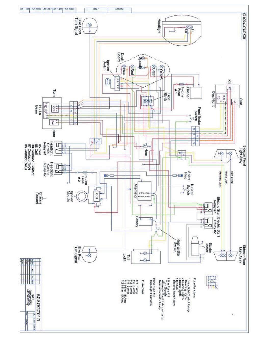
57 Chapter 11 ELECTRICAL EQUIPMENT The electrical equipment of the motorcycle includes power supplies, auxiliary in stru ments and electric wiring. Electric power supplies are a battery and an alternator with a built-in rectifier. A single wire system is used for wiring the electric circuits, i.e. a single wire carries power to the electrical devices and the frame and engine serve as the second wire (called the ground ). The neg a tive pole of the battery is con nect ed to the motorcycle engine The alternator makes electrical contact to the motorcycle engine and frame through its mount ing bolts. Battery supplies electric power to all the systems of the motorcycle when the en gine (and al ter na tor) have stopped. An alternator with a built-in rectifier is driven by the engine camshaft driven gear. The al ter na tor is secured with two studs on the engine crank case. At the drive side, the alternator cover is so designed that by turning the al ter na tor on the studs, the backlash adjustment of the gear mesh gap can be made. Electric horn. The motorcycle is equipped with a horn which sounds when the ignition is on and the horn button is pressed. The horn can be tuned for loudest performance with an adjusting screw lo cat ed at the rear por tion of the horn body. Headlight. A 7" diameter DOT approved sealed beam headlight is used on the Ural. Ad just it so that the high-beam is horizontal when the motorcycle is in its normal loaded condition. The stop light switch is secured on the frame bracket by means of two nuts. If the stop light either stays on or doesn t come on, loosen the nuts and adjust the stop light switch position either up or down on the frame & retighten the two nuts. 57
58 58
59 Electrical Circuits Lead acid batteries such as those found in motorcycles are designed for a charging voltage of volts. Batteries which are subjected to greater than volts for extended periods of time can suffer permanent damage due to the electrolyte boiling dry. Charging voltage of less than volts will result in an inadequate charge delivered to the battery. Automotive batteries operate at 12 volts. This is not enough voltage to harm people in any way. However, the battery stores a large amount of electricity in the form of electrons. If the electrons are allowed to flow from the battery without restriction, then the wires carrying the electricity will be come hot enough to melt. The melting wires are extremely dangerous and can easily burn you. Most problems in automotive electrical circuits are caused by poor connections. Make sure that all connection points are clean and tight. If the flow of electricity through a wire is interrupted due to a break in the wire or a poor con nec tion, then the circuit is said to be an open circuit The flow of electricity through a circuit always takes the path of least resistance. If there is an accidental path of extremely low resistance created in a circuit, the circuit is said to have a short circuit A short circuit will usually result in the melting of the fuse protecting that circuit. ELECTRICAL EQUIPMENT MAINTENANCE During the daily preventive inspection, check the functioning and the condition of the electrical equipment. Inspect and or replace the spark plugs and ignition leads as required in the Service Cou pons. The gap is re ad just ed by bend ing the end of the side elec trode. Care of alternator. In the course of daily inspection, check the fastening of wires to the alternator ter mi nals, fastening of the alternator on the engine crankcase, backlash of the gears (by listening). In case of too little backlash of the drive gear, excessive wear and overheating of the alternator bearings take place. Check for proper tightening of: nuts of the binding post bolts the alternator clamping screws the alternator fastening nuts as often as outlined in the Service Coupons. WARNING: Do not add any electrical accessories to your Ural motorcycle, as this will immediately void the warranty 59


60 The fuse box is located inside the headlight bucket The headlight control relays # 1 & 2 are located underneath the fuel tank. 60
61 Chapter 12 MAINTENANCE OF MOTORCYCLE Maintenance should be performed after the specified total kilometers run irrespective of the mechanical condition of the motorcycle. Different service duties and mechanical condition of the motorcycle may necessitate a change in the in ter vals. The Lubrication Chart indicating lubrication points of the motorcycle is given in Fig. 35. A sum ma ry of lubrication maintenance is given in the lubrication chart. Cosmetic Maintenance The enjoyment and resale value of your vehicle is greatly enhanced by consideration to the look and cosmetic perfection of your vehicle. Due to the numerous metal surfaces on a sidecar rig, special care must be taken to prevent rust from occurring and/or to removed any rust or oxidation. LIST OF RECOMMENDED LUBRICANTS Lubrication Area Detergent Oil Quantity Engine 20w/50 Castrol 68 oz. ( 2.0 L ) 1 Transmission 20w/50 Castrol 34 oz. ( 1.0 L ) 2 Single Wheel Final Drive 80/90 wt.gearlube 3.5 oz. ( 105 ml ) Dual Wheel Final Drive 80/90 wt.gearlube 4.5 oz. ( 135 ml ) 68 ozs is an approximate measure. The exact oil quantity will be whatever is required to bring the oil level at the top mark of the dipstick. 34 ozs is an approximate measure. The exact oil quantity will be whatever is required to bring the oil level up to the bot tom thread of the trans mis sion oil filler hole. 61
62 LUBRICATION CHART 62
63 ITEM PART TO BE LUBRICATED LUBRICANT 1 Engine crankcase 20W/50 Detergent Oil 2 Transmission 20W/50 Detergent Oil 3 Air cleaner JR Filter Oil 4 Telescopic forks 5wt-10wt Fork Oil 5 Final Drive 80/90 Gear oil 6 Hinges of sidecar collet joint Spindle oil & WD-40 7 Brake system hinge joints Spindle oil & WD-40 8 Brake pedal shaft Grease 9 Drive shaft universal joint Grease 10 Lever pins & end pieces of clutch & hand brake cables Grease 11 Pins & cams of brake shoes Grease 12 Wheel bearing Grease 13 Front forks Spindle oil & WD Carburetor throttle control twist grip Grease 15 Speedometer flexible drive cable & speedometer axle Spindle oil 16 Steering column bearings Grease REQUIRED LUBRICATION The Ural has been certified for EPA with SAE 20W/50 petroleum based detergent oil. This oil is used in both the engine and transmission. CARE OF MOTORCYCLE PAINT When washing the motorcycle, use a weak stream of cold or slightly heated water. Never use a pressure washer! Do not re move dust and mud by rubbing the surface with a dry cloth as sand par ti cles will de grade the surface and the paint will rapidly lose its brilliance. While washing, do not use soda so lu - tion, ker o sene, citric acids or mineral oils. If the surface is stained with mineral oil, degrease by wiping with a rag. If after removal of mud and dust with a jet of water, some dirt is left on the surface, remove it with the help of a sponge, a soft hair brush or a flannel and water, but not al low ing sep a rate water drops to dry out on the surface. Finally, polish the painted sur fac es with a dry soft flannel. 63
64 To repair painted areas, each motorcycle is furnished with a bottle of matching touch up paint. For patching proceed as follows: clean the surface with turpentine rub the damaged spot with a waterproof abrasive cloth and water rub thoroughly paint using a soft brush or a spray gun. After patching let the surface dry in air for 15 min, then proceed with drying at 212 F-248 F/100 C- 120 C with the aid of heat reflector or an electric lamp until the coat is per fect ly dry. Bear in mind that enamels are flammable. Color match may not be perfect due to humidity, fad ing, temperature and other variables. The painted surfaces of the motorcycle feature natural gloss. In case some dull spots appear, remedy them by polishing as follows. Take a solution of wax polishing compound and having washed the dull spots thoroughly, smear a thin film of the compound with a soft wad (cotton, cotton gauze or flannel) over the surface. Rub the polishing compound making circular mo tions with the wad. In 3-5 min. of drying, wipe the surface with a clean dry piece of cloth or flannel until luster appears. PRESERVATION AND STORAGE If the motorcycle is put in storage for the season, arrange it on supports and proceed with the preservation treatment. Check that the wheel tire pressure is within specifications. Store the mo tor cy cle away from acids, alkalis, mineral fertilizers and other harmful sub stanc es. Prior to placing it in storage, clean the bike thoroughly, drain the carburetors, or start the engine and let it run with the gas o line cock closed to remove gasoline in the float chambers of carburetors. Then spray storage oil (WD-40) into each cylinder through the spark plug holes. Turn the crank shaft by de press ing the kick lever pedal to distribute lubricant over the interior of the cylinders. Lu bri cate the sur fac es of chrome and zinc plated parts with a rust inhibitor. Smear all the points pro vid ed with grease cups with commercial grease. Seal the outlet holes of the mufflers. Before starting a trip on the motorcycle that was under preservation, proceed with the jobs listed in the section Pre-Trip Preliminaries. 64
65 Winter Considerations Motorists in many areas of the US experience the use of salt and other chemicals that are applied to road surfaces in the winter. Salt or other caustic chemicals should always be removed from your bike s surfaces with fresh water as soon as possible. Undercoating of fenders is recommended for those areas with salt and/or fine gravel or sand. See your dealer for details. BATTERY Storage batteries on the motorcycle should function at ambient air temperature from -40 C to plus 60 C/ 40 F to 140 F. As the battery is in service: regularly check the voltage for V do not allow the battery to discharge. use only distilled water to maintain the normal level of electrolyte. coat bolts, nuts, washers and tips with petroleum jelly or battery grease. Use two wrench es for clamping or undoing the nuts to avoid breaking battery parts. Warning: Do not short the terminals together to check for spark ing. Before storage, fully charge the batteries, wash the battery surface with water and wipe dry, clean the bolts and nuts of dirt. WARNING: BATTERIES CONTAIN SULFURIC ACID WHICH CAN CAUSE SEVERE BURNS. AVOID CON TACT WITH SKIN, EYES OR CLOTHING. ANTIDOTE: EXTERNAL FLUSH WITH WATER. INTERNAL DRINK LARGE QUANTITIES OF WATER FOLLOWED BY MILK OF MAGNESIA, VEGETABLE OIL, OR BEATEN EGGS. CALL DOCTOR IMMEDIATELY. Caution: When charging the battery, disconnect the positive terminal (+) from the battery to prevent damage to the electrical components Never jump-start the motorcycle! WARNING: BATTERIES PRODUCE EXPLOSIVE HYDROGEN GAS AT ALL TIMES ESPECIALLY WHEN BEING CHARGED. KEEP CIGARETTES, OPEN FLAME, AND SPARKS AWAY FROM BATTERY AT ALL TIMES. VENTILATE AREA WHEN CHARGING BATTERY. ALWAYS PROTECT HANDS AND PROTECT EYES WITH SHIELD OR GOG GLES WHEN WORKING NEAR A BATTERY OR ACID. KEEP BATTERIES AND ACID OUT OF THE REACH OF CHILDREN! 65
66 LIST OF INDIVIDUAL TOOL SET, SPARE PARTS, ACCESSORIES & DOCUMENTS DESCRIPTION QTY Tools 1. Wrench 7 x Wrench 10 x Wrench 13 x Wrench 14 x Wrench 19 x Socket wrench 10 x Socket wrench 10 x Socket wrench 19 x Wrench 27 mm Double head wrench Spanner wrench Spanner wrench assembly Screwdriver 150 mm Screwdriver 100 mm Punch Allen wrench 1 Accessories 1. Air Pump 1 Set of Spares 1. Oil filter element 1 2. Fuses 2 3. Touch up paint 1 Documents 1. Owners manual 1 66
67 67
68 68
Irbit Motorcycle Factory. Irbit Motorworks of America. Owners Manual Model Gear Up, Patrol, Tourist.
 Irbit Motorcycle Factory Irbit Motorworks of America Owners Manual 2003 Model Gear Up, Patrol, Tourist www.imz-ural.com 2 Contents Introduction...7 Warnings, Cautions, Notes...9 Chapter 1 Specifications
Irbit Motorcycle Factory
 Irbit Motorcycle Factory Irbit Motorworks of America Owners Manual 2004 Model Wolf Contents Introduction...5 Warnings, Cautions, Notes...5 Chapter 1 Specifications Specifications... 7 Torque Specifications...
URAL Motorcycles. Owner s Manual Model Retro Solo. Irbit Motorworks of America Inc NE 95th St Redmond WA
 URAL Motorcycles Owner s Manual 2004 Model Retro Solo Irbit Motorworks of America Inc. 15411 NE 95th St Redmond WA 98052 www.imz-ural.com Contents Introduction... 5 Warnings, Cautions, Notes... 5 Chapter
ATV-320 R OWNER S MANUAL
 ATV-320 R OWNER S MANUAL FOREWORD May we, the manufacturer, take this opportunity to thank you for choosing our ATV to serve you. This Owner s Manual is prepared for you to properly operate in safety.
ATV-320 S/U ATV-320SD S/U OWNER S MANUAL V
 ATV-320 S/U ATV-320SD S/U OWNER S MANUAL V1.0 2014.03.01 0 FOREWORD May we, the manufacturer, take this opportunity to thank you for choosing our ATV to serve you. This Owner s Manual is prepared for you
INSPECTION/ADJUSTMENT
 3 3 INSPECTION/ADJUSTMENT SERVICE INFORMATION----------------------------------------------------------------------- 3-1 MAINTENANCE SCHEDULE-------------------------------------------------------------------
PERIODIC MAINTENANCE
 PERIODIC MAINTENANCE CONTENTS PERIODIC MAINTENANCE SCHEDULE 2 1 MAINTENANCE PROCEDURES 2 3 2 BATTERY 2 3 CYLINDER HEAD NUTS AND EXHAUST PIPE NUTS 2 4 CYLINDER HEAD AND CYLINDER 2 4 SPARK PLUG 2 4 FUEL
I: INSPECT AND CLEAN, ADJUST, LUBRICATE OR REPLACE IF NECESSARY C: CLEAN A: ADJUST R: REPLACE L: LUBRICATE I: INSPECTION D: DIAGNOSE
 2. Periodic Maintenance > Periodic Maintenance Chart XCITING 400i Maintenance Schedule Perform the pre-ride inspection (Owner's Manual) at each scheduled maintenance period. This interval should be judged
3. INSPECTION/ADJUSTMENT
 3 3 INSPECTION/ADJUSTMENT SERVICE INFORMATION -------------------------------------------- 3-1 MAINTENANCE SCHEDULE ---------------------------------------- 3-2 FUEL LINE/FUEL FILTER -------------------------------------------
1.CONTENTS 1. Contents Control location Before riding Safe riding Driving Use genuine spare parts Use
 1.CONTENTS 1. Contents... 1 2. Control location... 3 3. Before riding... 4 4. Safe riding... 4 5. Driving... 5 6. Use genuine spare parts... 5 7. Use of each component... 6 Gauges... 6 Operation of ignition
NOTES FOR SAFETY OPERATOR-ONLY.
 NOTES FOR SAFETY Both the parents and their child must fully understand everything in this manual before riding. This vehicle is for OPERATOR-ONLY. This vehicle is only designed for operation on level,
3. INSPECTION/ADJUSTMENT
 SERVICE INFORMATION...3-0 FINAL REDUCTION GEAR OIL...3-7 MAINTENANCE SCHEDULE...3-2 DRIVE BELT...3-7 FUEL FILTER...3-3 BRAKE SHOE...3-8 THROTTLE OPERATION...3-3 BRAKE ADJUSTING NUT...3-8 AIR CLEANER...3-4
May we, the manufacturer, take this opportunity to thank you for choosing our ATV to serve you.
 FOREWORD May we, the manufacturer, take this opportunity to thank you for choosing our ATV to serve you. This Owner s Manual is prepared for you the details as to operate and maintenance necessarily to
BT49QT-9O3 User s Manual
 BT49QT-9O3 User s Manual Preface Thank you very much for purchasing BAOTIAN brand motorcycle of model BT49QT-9O3, which developed by BAOTIAN MOTORCYCLE INDUSTRIAL CO., LTD. And welcome to join the driver
3. INSPECTION/ADJUSTMENT
 3 SERVICE INFORMATION...3-0 FINAL REDUCTION GEAR OIL...3-7 MAINTENANCE SCHEDULE...3-2 DRIVE BELT...3-7 FUEL FILTER...3-3 BRAKE SHOE...3-8 THROTTLE OPERATION...3-3 BRAKE ADJUSTING NUT...3-8 AIR CLEANER...3-4
COLT 2310, 2510, AND 2712 COM PACT TRACTORS CHAPTER 9 TROUBLESHOOTING AND ANALYSIS
 COLT 2310, 2510, AND 2712 COM PACT TRACTORS CHAPTER 9 TROUBLESHOOTING AND ANALYSIS 9-A-1 UPON RECEIVING ANENGINE FORRE- PAIR. Learn the history of the unit from the customer. While the customer is present
ATV-50/90/100 I/II/V OWNER S MANUAL
 1 ATV-50/90/100 I/II/V OWNER S MANUAL FOREWORD May we, the manufacturer, take this opportunity to thank you for choosing our ATV to serve you. This Owner s Manual is prepared for you the details as to
Typical Install Instructions
 Typical Install Instructions Read & understand all steps of these instructions before beginning this installation. WEBER Conversion Kit, VW T-1/2, up to 1835cc 32 / 36 DFEV Weber Carburetor These instructions
Racing NAVODILO ZA UPORABO USER'S MANUAL
 Racing NAVODILO ZA UPORABO USER'S MANUAL TOMOS USER'S MANUAL YOUNGST'R YOUNGST'R FULL RACING 45 1 CONTENTS Warnings 3 Riding Safety Tips 3 Technical Specification 4-5 Technical Description 6-9 Vehicle
SECTION 6 3 SERVICE PROCEDURES AND SPECIFICATIONS. Chassis
 SERVICE PROCEDURES AND SPECIFICATIONS Chassis SECTION 6 3 Specifications........................................... 208 Checking brake fluid...................................... 210 Checking power steering
CHASSIS CONTENTS EXTERIOR PARTS 6-1 FRAME COVER 6-2 REAR FRAME COVER 6-4 FRONT WHEEL 6-6 FRONT BRAKE 6-10 HANDLEBARS 6-17 FRONT FORK 6-19
 CHASSIS CONTENTS EXTERIOR PARTS 6- FRAME COVER 6- REAR FRAME COVER 6-4 FRONT WHEEL 6-6 FRONT BRAKE 6-0 HANDLEBARS 6-7 FRONT FORK 6-9 STEERING 6-6 REAR WHEEL 6-3 REAR BRAKE 6-39 6 REAR SHOCK ABSORBER 6-43
Unit: mm (in) ITEM STANDARD LIMIT IN. 33 (1.3) EX.
 ITEM STANDARD LIMIT IN. 33 (1.3) EX.") Model: DR650SEL0 E-03, 24, 28, 33 Date: July 16, 2009 SERVICE DATA VALVE + GUIDE Valve diam. Valve clearance (when engine is cold) Valve guide to valve stem clearance Valve stem deflection Valve guide
Model: DR650SEL0 E-03, 24, 28, 33 Date: July 16, 2009 SERVICE DATA VALVE + GUIDE Valve diam. Valve clearance (when engine is cold) Valve guide to valve stem clearance Valve stem deflection Valve guide
ENGINE TUNE-UP INSPECTION OF ENGINE COOLANT INSPECTION OF ENGINE OIL INSPECTION OF BATTERY. INSPECTION OF AIR FILTER (Paper Filter Type)
") ENGINE MECHANICAL - Engine Tune-Up EM-17 ENGINE TUNE-UP INSPECTION OF ENGINE COOLANT (See steps 1 and 2 on page CO-4) INSPECTION OF ENGINE OIL (See steps 1 and 2 on page LU-5) INSPECTION OF BATTERY (See
ENGINE MECHANICAL - Engine Tune-Up EM-17 ENGINE TUNE-UP INSPECTION OF ENGINE COOLANT (See steps 1 and 2 on page CO-4) INSPECTION OF ENGINE OIL (See steps 1 and 2 on page LU-5) INSPECTION OF BATTERY (See
SECTION 6 3 SERVICE PROCEDURES AND SPECIFICATIONS. Chassis
 SECTION 6 3 SERVICE PROCEDURES AND SPECIFICATIONS Chassis Specifications 206 Checking brake fluid 208 Checking power steering fluid 209 Checking tire pressure 210 Rotating tires 211 Checking and replacing
Engine Does Not Start or Is Hard to Start Cause of Trouble. 1. Open the drain screw, and check Fuel not supplied (1) Fuel tank empty
 Fuel tank empty") 20. Engine Does Not Start or Is Hard to Start 20-1 Engine Output Insufficient 20-2 Poor Performance at Low Speed and Idling 20-3 Poor Performance at High Speed 20-3 Unsatisfactory Operation 20-4 Fuel Gauge
20. Engine Does Not Start or Is Hard to Start 20-1 Engine Output Insufficient 20-2 Poor Performance at Low Speed and Idling 20-3 Poor Performance at High Speed 20-3 Unsatisfactory Operation 20-4 Fuel Gauge
Operation and Maintenance Instructions for the RAPTOR 178
 WWW.SKYTOY.COM Operation and Maintenance Instructions for the RAPTOR 178 See www.skytoy.com for updates and service bulletins. 2/1/2011 1. Parts Schematic:... 3 2. Muffler Assembly Diagram:... 4 3. Muffler
SECTION 8 2 DO IT YOURSELF MAINTENANCE. Chassis
 DO IT YOURSELF MAINTENANCE Chassis SECTION 8 2 Checking the coolant level of the traction motor................ 184 Checking the radiator....................................... 185 Checking brake fluid........................................
IMPORTANT INFORMATION
 Table of Contents IMPORTANT INFORMATION Section 1B - Maintenance MAINTENANCE 1 B Specifications........................... 1B-1 Special Tools........................... 1B-2 Mercury/Quicksilver Lubricants
SMF / DSF / DTF SMF / DSF / DTF 200
 2006 SMF / DSF / DTF 200 1 The drawings in this parts book have been scaled so that parts can be easily recognized. 1 CYLINDER ASSY 2 CYLINDER ASSY Ref # Part # Description 1 410 0001A CYLINDER HEAD COVER
Valve + Valve Guide Unit: mm (in) Item Standard Limit Valve diam. IN (1.20) EX (1.06) Valve clearance (when cold)
 Item Standard Limit Valve diam. IN (1.20) EX (1.06) Valve clearance (when cold)") Model: LT-A400FL9 P-17, 24, 28,03 Date: Feb. 12, 2018 SERVICE DATA Valve + Valve Guide Valve diam. IN. 30.6 (1.20) EX. 27.0 (1.06) Valve clearance (when cold) IN. 0.05 0.10 (0.002 0.004) EX. 0.22 0.27
Model: LT-A400FL9 P-17, 24, 28,03 Date: Feb. 12, 2018 SERVICE DATA Valve + Valve Guide Valve diam. IN. 30.6 (1.20) EX. 27.0 (1.06) Valve clearance (when cold) IN. 0.05 0.10 (0.002 0.004) EX. 0.22 0.27
1. GENERAL INFORMATION
 GENERAL INFORMATION ENGINE SERIAL NUMBER ---------------------------------------------- - SPECIFICATIONS ---------------------------------------------------------- - 2 SERVICE PRECAUTIONS ------------------------------------------------
INSTALLATION INSTRUCTIONS
 INSTALLATION INSTRUCTIONS REAR DISC CONVERSION KIT A126-2 1988-98 C1500 2WD 10" REAR DRUM Thank you for choosing STAINLESS STEEL BRAKES CORPORATION for your braking needs. Pleases take the time to read
Part list for Kawasaki H2, 1972
 Part list for Kawasaki H2, 972 . Cylinder head, cylinder. . Cylinder head, cylinder. 9205-049 NUT 0 m/m 2 2 40B400 WASHER-plain 4 m/m 2 3 46E400 WASHER-spring 4 m/m 2 4 92070-036 SPARK PLUG NGK B9 HS 3
CHASSIS CONTENTS EXTERIOR PARTS 7-1 FRONT WHEEL 7-2 FRONT BRAKE 7-6 HANDLEBARS 7-13 FRONT FORK 7-15 STEERING 7-23 REAR WHEEL 7-26 REAR BRAKE 7-30
 CHASSIS CONTENTS EXTERIOR PARTS 7- FRONT WHEEL 7-2 FRONT BRAKE 7-6 HANDLEBARS 7-3 FRONT FORK 7-5 STEERING 7-23 REAR WHEEL 7-26 REAR BRAKE 7-30 REAR SHOCK ABSORBER 7-32 SWING ARM 7-33 7 7- CHASSIS EXTERIOR
WEBER CARBURETOR TROUBLESHOOTING GUIDE
 This guide is to help pinpoint problems by diagnosing engine symptoms associated with specific vehicle operating conditions. The chart will guide you step by step to help correct these problems. For successful
BRAKE SYSTEM Return To Main Table of Contents
 BRAKE SYSTEM Return To Main Table of Contents GENERAL... 2 BRAKE PEDAL... 10 MASTER CYLINDER... 13 BRAKE BOOSTER... 16 BRAKE LINE... 18 PROPORTIONING VALVE... 19 FRONT DISC BRAKE... 20 REAR DRUM BRAKE...
12. FRONT WHEEL/FRONT BRAKE/
 12 4.5kgm 0.9kg-m 4.5kg-m 12-0 SERVICE INFORMATION... 12-1 HYDRAULIC BRAKE... 12-10 TROUBLESHOOTING... 12-2 FRONT SHOCK ABSORBER... 12-16 FRONT WHEEL... 12-3 STEERING HANDLEBAR... 12-19 FRONT BRAKE...
PARTS CATALOGUE. Rockford Motors inc.
 PARTS CATALOGUE Rockford Motors inc. INSTRUCTIONS FOR USING THE PARTS CATALOGUE 1. This catalogue covers all the items of genuine parts and tools of BRIDGESTONE 350 GTR and 350 GTO motorcycles. 2. Please
BRIDGESTONE M 1)RCYCLES TUNING UP
RCYCLES TUNING UP") BRIDGESTONE M 1)RCYCLES TUNING UP BRIDGESTONE MOTORCYCLES TUNING UP FOR COMPETITION CONTENTS Introduction... 4 Tuning up 350 GTR for Road Racing...,... 7 Tuning up 350 GTR for Scrambling... 10 Tuning up
BRIDGESTONE M 1)RCYCLES TUNING UP BRIDGESTONE MOTORCYCLES TUNING UP FOR COMPETITION CONTENTS Introduction... 4 Tuning up 350 GTR for Road Racing...,... 7 Tuning up 350 GTR for Scrambling... 10 Tuning up
Motorcycle - Specifications
 Motorcycle - Specifications Model Name FZ400R Model Code 46X0 Model Year 1985 Destination JAPAN Section/Item Chassis Maintenance Specification (Chassis) Chassis Frame type Double cradle Caster angle 26.00
John Deere. MODEL: 1010 Gasoline Wheel Tractor JD-O-OMT15504
 John Deere MODEL: Gasoline Wheel Tractor THIS IS A MANUAL PRODUCED BY JENSALES INC. WITHOUT THE AUTHORIZATION OF JOHN DEERE OR IT'S SUCCESSORS. JOHN DEERE AND IT'S SUCCESSORS ARE NOT RESPONSIBLE FOR THE
Part 7 DO IT YOURSELF MAINTENANCE
 Part 7 DO IT YOURSELF MAINTENANCE Chapter 7 2 Engine and Chassis Checking the engine oil level Checking the engine coolant level Checking brake fluid Checking power steering fluid Checking tire pressure
1,000 LB. CAPACITY TELESCOPIC TRANSMISSION JACK WITH AIR PUMP
 QTJ01A 1,000 LB. CAPACITY TELESCOPIC TRANSMISSION JACK WITH AIR PUMP Address: 200 Cabel St. Louisville, KY 40206. Sales and Service: 1-877-771-5438. Fax: 502-583-5488. Website: www.qualitylifts.com SPECIFICATIONS
MOTORINI GP 50. User s Manual.
 MOTORINI GP 50 User s Manual www.motorini.co.uk Dear user: Thank you for choosing to buy a Motorini GP 50 This manual provides the correct operation and maintenance methods for safe riding and maintaining
SECTION 4A BRAKE SYSTEM TABLE OF CONTENTS
 SECTION 4A BRAKE SYSTEM TABLE OF CONTENTS Description and Operation... 4A-2 Braking System Testing... 4A-2 Hydraulic Brake System... 4A-2 Brake Pedal... 4A-2 Master Cylinder... 4A-2 Brake Booster... 4A-3
CONTENT. 3. Maintenance
 CONTENT Foreword -------------------------------------------------------------------------------------------- 1 1. The performance, technical parameters and structure of Go Kart--------------------------------------------2
CHASSIS CONTENTS FRONT WHEEL 6-1 FRONT BRAKE 6-6 FRONT FORK 6-14 STEERING STEM 6-20 REAR WHEEL AND REAR BRAKE 6-25 SUSPENSION 6-31 REAR SWING ARM 6-36
 CHASSIS CONTENTS FRONT WHEEL 6-1 FRONT BRAKE 6-6 FRONT FORK 6-14 STEERING STEM 6-20 REAR WHEEL AND REAR BRAKE 6-25 SUSPENSION 6-31 REAR SWING ARM 6-36 6 6-1 CHASSIS FRONT WHEEL REMOVAL Support the machine
SRT OPERATIONS MANUAL
 MAINTENANCE SECTION PAGE # VEHICLE DAILY INSPECTION.......................................1 P.M. INSPECTION #1.................................................3 P.M. INSPECTION #2.................................................6
5. FUEL SYSTEM 5-0 FUEL SYSTEM UXV 500
 5 FUEL SYSTEM 5 SERVICE INFORMATION------------------------------------------------ 5-02 TROUBLESHOOTING----------------------------------------------------- 5-03 FUEL TANK -----------------------------------------------------------------
A SYSTEMATIC SEQUENCE FOR PM INSPECTIONS
 A SYSTEMATIC SEQUENCE FOR PM INSPECTIONS TYPE OF INSPECTION UNDER THE HOOD GASOLINE AND DIESEL 1 Fuel, oil, exhaust leaks - inspect 2 Oil and fuel lines inspect for kinks and wear 3 Automatic transmission
11/14/ U. Baja Motorsports Inc. P.O. Box Phoenix, AZ Toll Free: PARTS AND PRICES ARE SUBJECT TO CHANGE 1 of 53
 250U Toll Free: 888-863-2252 PARTS AND PRICES ARE SUBJECT TO CHANGE 1 of 53 FIG. 1 PNEUMATIC MECHANISM 1-1 250U-100 883099019951 CAMSHAFT 1 1 1-2 250U-101 883099019968 KEY, WOODRUFF 1 1 1-3 250U-102 883099019975
Northern Arizona University Baja SAE Owner s Manual
 Northern Arizona University Baja SAE 2016 Owner s Manual Contents Vehicle Overview... 2 Safety Equipment... 3 Seat... 3 Safety Harness... 3 Emergency Stop... 3 Fire Extinguisher... 3 Vehicle Operation...
ATV 300 DVX CAT GREEN (A2011KSF2BUSZ) Page 1 of 56 AIR INTAKE ASSEMBLY
 Page 1 of 56 AIR INTAKE ASSEMBLY") 2011 ATV 300 DVX CAT GREEN (A2011KSF2BUSZ) Page 1 of 56 AIR INTAKE ASSEMBLY 2011 ATV 300 DVX CAT GREEN (A2011KSF2BUSZ) Page 2 of 56 AIR INTAKE ASSEMBLY Ref # Part Number Qty S/P/F Description 1 3303-705
2011 ATV 300 DVX CAT GREEN (A2011KSF2BUSZ) Page 1 of 56 AIR INTAKE ASSEMBLY 2011 ATV 300 DVX CAT GREEN (A2011KSF2BUSZ) Page 2 of 56 AIR INTAKE ASSEMBLY Ref # Part Number Qty S/P/F Description 1 3303-705
12. FRONT WHEEL/FRONT BRAKE/
 12 12 12-0 SERVICE INFORMATION... 12-1 FRONT BRAKE... 12-7 TROUBLESHOOTING... 12-2 FRONT SHOCK ABSORBER... 12-18 STEERING HANDLEBAR... 12-3 FRONT FORK... 12-21 FRONT WHEEL... 12-4 SERVICE INFORMATION GENERAL
SERVICE DATA. Unit: mm (in) ITEM STANDARD LIMIT Valve diam. IN (1.42) EX ( ) EX.
 ITEM STANDARD LIMIT Valve diam. IN (1.42) EX ( ) EX.") 4 STROKE VALVE + VALVE GUIDE CAMSHAFT + CYLINDER HEAD SERVICE DATA Valve diam. 36.0 (1.42) 33.0 (1.30) Tappet clearance (when cold) 0.10 0.20 (0.004 0.008) 0.20 0.30 (0.008 0.012) Valve guide to valve
4 STROKE VALVE + VALVE GUIDE CAMSHAFT + CYLINDER HEAD SERVICE DATA Valve diam. 36.0 (1.42) 33.0 (1.30) Tappet clearance (when cold) 0.10 0.20 (0.004 0.008) 0.20 0.30 (0.008 0.012) Valve guide to valve
Light condition and operation Windshield glass condition Wiper blade condition Paint condition and corrosion Fluid leaks Door and hood lock condition
 GENERAL CHECKS Engine Compartment The following should be checked regularly: Engine oil level and condition Transmission fluid level and condition Brake fluid level Clutch fluid level Engine coolant level
Instruction Model 18537
 Instruction 738-556 Model 18537 LIMITED WARRANTY H. D. Hudson Manufacturing Company warrants to the original purchaser only that this product will continue to function as intended if used in accordance
SERVICE DATA Date: August 1, 2007
 SERVICE DATA Date: August 1, 2007 Model: LT-A450XK8 VALVE + VALVE GUIDE Valve diam. 30.6 IN. (1.20) EX. 27.0 (1.06) Tappet clearance (when cold) 0.05 0.10 IN. (0.002 0.004) EX. 0.17 0.22 (0.007 0.009)
1992 Clutch. Eclipse, Expo/Expo LRV, Galant, Mirage, Precis, 3000GT
 Article Text ARTICLE BEGINNING 1992 Clutch Eclipse, Expo/Expo LRV, Galant, Mirage, Precis, 3000GT DESCRIPTION All clutches are single disc type. Pressure plate assembly uses a diaphragm spring to engage
PRE-TRIP INSPECTION CDL SKILLS TEST
 CDL SKILLS TEST PRE-TRIP INSPECTION Engine Compartment +1 Axle Side and Back of Truck +1 Axle Connections and Trailer +1 Axle External Light Check In-Cab with Brake Check 1810 N WATKINS RD, WATKINS, CO
SF-120, SF-170, SF-250, SF-400 Bearing Mounted, Flange Mounted, SFC-120, SFC-170, SFC-250, SFC-400 Bearing Mounted, Flange Mounted
 SF-120, SF-170, SF-250, SF-400 Bearing Mounted, Flange Mounted, SFC-120, SFC-170, SFC-250, SFC-400 Bearing Mounted, Flange Mounted P-0200-WE 819-0481 Installation Instructions An Altra Industrial Motion
3. INSPECTION/ADJUSTMENT
 3 3 INSPECTION/ADJUSTMENT SERVICE INFORMATION-------------------------------------------------- 3-1 MAINTENANCE SCHEDULE---------------------------------------------- 3-3 FUEL LINE---------------------------------------------------------------------
SECTION 6 3 SERVICE PROCEDURES AND SPECIFICATIONS. Chassis
 SERVICE PROCEDURES AND SPECIFICATIONS Chassis SECTION 6 3 Specifications........................................... 204 Checking brake fluid...................................... 206 Checking brake pedal
ATV I l. l u. r a. Parts Manual ARCTIC CAT. 250 cc/300 cc
 2000 I l l u st ATV 250 cc/300 cc Model No. A2000ATE2AUSG (250 - Green) Model No. A2000ATE2AUSR (250 - Red) Model No. A2000ATF2AUSG (300 2x4 - Green) Model No. A2000ATF2AUSR (300 2x4 - Red) Model No. A2000ATF4AUSG
ATV 90 UTILITY GREEN (A2006KUB2BUSG) Page 1 of 60 AIR INTAKE ASSEMBLY
 Page 1 of 60 AIR INTAKE ASSEMBLY") 2006 ATV 90 UTILITY GREEN (A2006KUB2BUSG) Page 1 of 60 AIR INTAKE ASSEMBLY 2006 ATV 90 UTILITY GREEN (A2006KUB2BUSG) Page 2 of 60 AIR INTAKE ASSEMBLY Ref # Part Number Qty S/P/F Description 1 3303-005
2006 ATV 90 UTILITY GREEN (A2006KUB2BUSG) Page 1 of 60 AIR INTAKE ASSEMBLY 2006 ATV 90 UTILITY GREEN (A2006KUB2BUSG) Page 2 of 60 AIR INTAKE ASSEMBLY Ref # Part Number Qty S/P/F Description 1 3303-005
SECTION 3.00 WARNING WARNING ENGINE STARTUP AND SHUTDOWN PRESTART INSPECTION
 SECTION 3.00 ENGINE STARTUP AND SHUTDOWN PRESTART INSPECTION Be sure that the clutch, circuit breaker, or other main power transmission device is disconnected. Generators develop voltage as soon as the
Carburetor Instructions
 Carburetor Instructions for HUDSON SUPER SIX ESSEX SIX CYLINDER Hudson Motor Car Co. DETROIT, U.S.A. Carburetor The carburetor is a device for metering correct amounts of fuel and air for the various
SERVICE DATA. Item Standard Limit Valve diam. IN (1.42) EX (1.30) Tappet clearance (When cold)
 EX (1.30) Tappet clearance (When cold)") Model: LT-A750XK9 P-17, 24, 28, 33 LT-A750XZK9 P-17, 28, 33 4 STROKE Camshaft + Cylinder Head SERVICE DATA Valve + Guide Valve diam. IN. 36.0 (1.42) EX. 33.0 (1.30) Tappet clearance (When cold) IN. 0.10
Model: LT-A750XK9 P-17, 24, 28, 33 LT-A750XZK9 P-17, 28, 33 4 STROKE Camshaft + Cylinder Head SERVICE DATA Valve + Guide Valve diam. IN. 36.0 (1.42) EX. 33.0 (1.30) Tappet clearance (When cold) IN. 0.10
Gasoline Inverter Generator
 user manual Gasoline Inverter Generator table of contents Preface Introduction... Safety Information Exhaust fumes are poisonous... Fuel is highly flammable and poisonous... Engine and muffler may be hot...
SECTION ZF FRONT AXLE
 04-101.01/ 1 2011JA14 SECTION 04-101.01 6 3 5 1 2 9 1. Upper radius rod 2. Lower radius rod 3. Caliper 4. BRAKE Disk 5. Pneumatic connector 6. Hub 7. steering knuckle 8. Grease Fitting 9. Pneumatic connector
User Manual of Bagibike Electric Bicycles
 User Manual of Bagibike Electric Bicycles Model: Bagibike B16. http://www.bagibike.com Page 1 FOREWORD The following operation manual is a guide to assist you. This manual is not a complete document on
DVX 300 Euro. Model Number A2012KSF2BEUK SHARE OUR PASSION.
 ATV 2012ATV Illustrated Parts Manual DVX 300 Euro Model Number A2012KSF2BEUK TM SHARE OUR PASSION. TABLE OF CONTENTS 2012 ATV DVX 300 Euro (Model No. A2012KSF2BEUK) BODY PANEL AND HEADLIGHT ASSEMBLY...
WARNING: the engine does not come with oil in it. Please fill the oil before starting. The 200cc hardknock requires 9/10 of a quart of oil.
 WARNING: the engine does not come with oil in it. Please fill the oil before starting. The 200cc hardknock requires 9/10 of a quart of oil. Things needed for assembly. -2 tubes of blue loc-tite. I don
SECTION 1-6 OPERATION OF INSTRUMENTS AND CONTROLS 05 HIGHLANDER_U (L/O 0409) Gauges, Meters and Service reminder indicators
 Gauges, Meters and Service reminder indicators") SECTION 1-6 OPERATION OF INSTRUMENTS AND CONTROLS Gauges, Meters and Service reminder indicators Fuel gauge................................................ 132 Engine coolant temperature gauge...........................
SECTION 1-6 OPERATION OF INSTRUMENTS AND CONTROLS Gauges, Meters and Service reminder indicators Fuel gauge................................................ 132 Engine coolant temperature gauge...........................
SERVICE INFORMATION 11-1 FRONT WHEEL/SUSPENSION/ STEERING XL FRONT WHEEL 11 7 FORK STEERING STEM 11 18
 XL200 11. FRONT WHEEL/SUSPENSION/ STEERING SERVICE INFORMATION 11 1 TROUBLESHOOTING 11 2 HANDLEBAR 11 3 FRONT WHEEL 11 7 FORK 11 11 STEERING STEM 11 18 SERVICE INFORMATION GENERAL A contaminated brake
FUEL SYSTEM. Table of Contents. Specifications. Section 3A Fuel Delivery System. Models 6/8/9.9/10/15 CARBURETOR SPECIFICATIONS
 FUEL SYSTEM Section 3A Fuel Delivery System Table of Contents Specifications............................. 3A-1 WMC Carburetor Specifications............. 3A-2 WMC Carburetor Specifications.............
SECTION 3 STARTING AND DRIVING MR2 U
 STARTING AND DRIVING SECTION 3 Before starting the engine................................... 122 How to start the engine...................................... 122 Tips for driving in various conditions...........................
Parts Diagrams RR/RS Models
 Parts Diagrams 2008-2009 RR/RS Models Table Of Contents Description Page # front fork 1 handlebar, clutch pump, meter (RR Models) 2 handlebar, clutch pump, meter (RS Models) 3 frame, subframe 4 rear shock,
1.6L 4-CYL - VIN [E]
![1.6L 4-CYL - VIN [E]](/thumbs/81/84172348.jpg "1.6L 4-CYL - VIN [E]") 1.6L 4-CYL - VIN [E] 1993 Nissan Sentra 1993 NISSAN ENGINES 1.6L 4-Cylinder NX, Sentra * PLEASE READ THIS FIRST * NOTE: For engine repair procedures not covered in this article, see ENGINE OVERHAUL PROCEDURES
1.6L 4-CYL - VIN [E] 1993 Nissan Sentra 1993 NISSAN ENGINES 1.6L 4-Cylinder NX, Sentra * PLEASE READ THIS FIRST * NOTE: For engine repair procedures not covered in this article, see ENGINE OVERHAUL PROCEDURES
SECTION 4 - FUEL/LUBRICATION/COOLING
 For Arctic Cat Discount Parts Call 606-678-9623 or 606-561-4983 SECTION 4 - FUEL/LUBRICATION/COOLING 4 TABLE OF CONTENTS Carburetor Specifications... 4-2 Carburetor Schematic... 4-2 Carburetor... 4-3 Cleaning
~. a~' ~ ( I o~~~ 4-0. ~Sj~' AO~ i/~ CB1000C (ij)aon'da in-ib) ~ "" ~ ~!~~P. ~ J N m (6-12 kg-em,
aon'da in-ib) ~ ~ ~!~~P. ~ J N m (6-12 kg-em,") e V ~. a~' ~ I ~ J C t \"" 8.0- ( I o~~~ ~ "" ~ ~. ~!~~P. C8 0 & 0,-t. ~ CB1000C (ij)aon'da 0.6-1.2 N m (6-12 kg-em, 5-10 in-ib) 4-0 / 4.0-6.0 N m (40-60 kg-em, 35-52 in-i b) t$ "'07~ / c;:::/ j ~Sj~'
e V ~. a~' ~ I ~ J C t \"" 8.0- ( I o~~~ ~ "" ~ ~. ~!~~P. C8 0 & 0,-t. ~ CB1000C (ij)aon'da 0.6-1.2 N m (6-12 kg-em, 5-10 in-ib) 4-0 / 4.0-6.0 N m (40-60 kg-em, 35-52 in-i b) t$ "'07~ / c;:::/ j ~Sj~'
GTS150. Dune Buggy MINIMUM RECOMMENDED OPERATOR AGE: FOR OFF-ROAD USE ONLY. 10th letter in VIN: D-G
 0-06 GTS50 0th letter in VIN: D-G Dune Buggy MINIMUM RECOMMENDED OPERATOR AGE: 6 FOR OFF-ROAD USE ONLY This vehicle is designed and manufactured for off-road use only. USA only: It does not conform to
Tech Note Truck 14 & 15.5 Twin Plate Cast Iron Type Installation Guidelines
 1. (14 & 15.5 ) Check condition of the flywheel. Grind to resurface or replace flywheel. Surface MUST BE machined or premature clutch failure can occur. Flywheel depth must be 2.938 (74.62mm) for 14 (350mm)
Sherco Setup and Lubrication Guide
 Sherco Setup and This guide is designed to provide the Sherco owner with instructions on how to: Set up a new bike Clean and re-oil the air filter Change the transmission oil Change the fork oil Repack
AIR BRAKES THIS SECTION IS FOR DRIVERS WHO DRIVE VEHICLES WITH AIR BRAKES
 Section 5 AIR BRAKES THIS SECTION IS FOR DRIVERS WHO DRIVE VEHICLES WITH AIR BRAKES AIR BRAKES/Section 5 SECTION 5: AIR BRAKES THIS SECTION COVERS Air Brake System Parts Dual Air Brake Systems Inspecting
ATV 90 UTILITY CALIFORNIA GREEN (A2008KUB2BCAG) Page 1 of 58 AIR INTAKE ASSEMBLY
 Page 1 of 58 AIR INTAKE ASSEMBLY") 2008 ATV 90 UTILITY CALIFORNIA GREEN (A2008KUB2BCAG) Page 1 of 58 AIR INTAKE ASSEMBLY 2008 ATV 90 UTILITY CALIFORNIA GREEN (A2008KUB2BCAG) Page 2 of 58 AIR INTAKE ASSEMBLY Ref # Part Number Qty S/P/F Description
2008 ATV 90 UTILITY CALIFORNIA GREEN (A2008KUB2BCAG) Page 1 of 58 AIR INTAKE ASSEMBLY 2008 ATV 90 UTILITY CALIFORNIA GREEN (A2008KUB2BCAG) Page 2 of 58 AIR INTAKE ASSEMBLY Ref # Part Number Qty S/P/F Description
Series 1000 and Cutout
 17.15.Remove the belt from the tractor. NOTE: There were a small number of tractors made using a CVT drive and a 2-speed (L-H-N-R) GT transaxle. The belt must pass over the center mounted gear selector
Department of Motor Vehicles Loudoun County Public Schools School Bus Inspection Study Guide Hand Out
 Department of Motor Vehicles Loudoun County Public Schools School Bus Inspection Study Guide Hand Out During the actual tests, you will be expected to point or touch each of the parts of your vehicle.
SECTION 7 2 DO IT YOURSELF MAINTENANCE MR2 U. Engine and Chassis
 SECTION 7 2 DO IT YOURSELF MAINTENANCE Engine and Chassis Checking the engine oil level................................. 168 Checking the engine coolant level............................ 169 Checking brake
401 0 Row-Crop & Standard Tractors
 John Deere MODEL: 401 0 Row-Crop & Standard Tractors THIS IS A MANUAL PRODUCED BY JENSALES INC. WITHOUT THE AUTHORIZATION OF JOHN DEERE OR IT'S SUCCESSORS. JOHN DEERE AND IT'S SUCCESSORS ARE NOT RESPONSIBLE
Owner s Manual for 16 Slider
 Owner s Manual for 16 Slider This manual contains important safety, assembly, operation and maintenance information. Please read and fully understand this manual before operation. Save this manual for
SERVICE DATA ITEM STD/SPEC. LIMIT. ( in) 1st & 2nd R Approx. 8.2 mm (0.32 in)
 1st & 2nd R Approx. 8.2 mm (0.32 in)") 2 STROKE CYLINDER + PISTON + PISTON RING CONROD + CRANKSHAFT CLUTCH SERVICE DATA Piston to cylinder clearance 0.045 0.055 mm (0.0018 0.0022 in) 0.120 mm (0.0047 in) Cylinder bore Piston diam. Cylinder
2 STROKE CYLINDER + PISTON + PISTON RING CONROD + CRANKSHAFT CLUTCH SERVICE DATA Piston to cylinder clearance 0.045 0.055 mm (0.0018 0.0022 in) 0.120 mm (0.0047 in) Cylinder bore Piston diam. Cylinder
INSTALLATION & USER S GUIDE
 REKLUSE MOTOR SPORTS The Rekluse Core EXP Kit for Kawasaki KX80/85/100 OVERVIEW INSTALLATION & USER S GUIDE Doc ID: 191-7742A Doc Rev: 073015 This kit replaces the OEM core clutch components including
OWNERS MANUAL. Two Stroke Dirt Bike. Distributed by SSR Motorsports. Address: Alondra Blvd, Norwalk CA
 OWNERS MANUAL Two Stroke Dirt Bike Distributed by SSR Motorsports Address: 12825 Alondra Blvd, Norwalk CA 90650 www.ssrmotorsports.com Please note that this is a general manual. The model of the vehicle
SECTION 4A HYDRAULIC BRAKES
 SECTION 4A HYDRAULIC BRAKES CAUTION: Disconnect the negative battery cable before removing or installing any electrical unit or when a tool or equipment could easily come in contact with exposed electrical
400 4x4 Euro MODEL NUMBER A2008IDG4BEUR (RED) MODEL NUMBER A2008IDG4BEUG (GREEN) MODEL NUMBER A2008IDG4BEUZ (CAT GREEN) MORE TO GO ON.
 MODEL NUMBER A2008IDG4BEUG (GREEN) MODEL NUMBER A2008IDG4BEUZ (CAT GREEN) MORE TO GO ON.") 2008 400 4x4 Euro Illustrated Parts Manual MODEL NUMBER A2008IDG4BEUR (RED) MODEL NUMBER A2008IDG4BEUG (GREEN) MODEL NUMBER A2008IDG4BEUZ (CAT GREEN) MORE TO GO ON. TM TABLE OF CONTENTS 2008 ATV 400 4x4
2008 400 4x4 Euro Illustrated Parts Manual MODEL NUMBER A2008IDG4BEUR (RED) MODEL NUMBER A2008IDG4BEUG (GREEN) MODEL NUMBER A2008IDG4BEUZ (CAT GREEN) MORE TO GO ON. TM TABLE OF CONTENTS 2008 ATV 400 4x4
John Deere. MODEL: 2030 Tractor JD-O-OMR50675
 John Deere MODEL: 2030 Tractor THIS IS A MANUAL PRODUCED BY JENSALES INC. WITHOUT THE AUTHORIZATION OF JOHN DEERE OR IT'S SUCCESSORS. JOHN DEERE AND IT'S SUCCESSORS ARE NOT RESPONSIBLE FOR THE QUALITY
2010 INDIAN MOTORCYCLE PRE- DELIVERY AND INSPECTION
 2010 INDIAN MOTORCYCLE PRE- DELIVERY AND INSPECTION Table of Contents Introduction 1 Preparing the motorcycle.... 2 Pre-Delivery Checklist...... 4 Customer Acceptance........ 6 Introduction For your own
Illustrated Parts Manual. Model Number A2011KSF2BEUZ (Black-Cat Green) A2011KSF2BEOJ (White-Cat Green)
 A2011KSF2BEOJ (White-Cat Green)") Illustrated Parts Manual 2 1 10 DVX 300 Euro Model Number A2011KSF2BEUZ (Black-Cat Green) A2011KSF2BEOJ (White-Cat Green) S H A R E O U R PAS S IO N. TM TABLE OF CONTENTS 2011 ATV DVX 300 Euro Black-Cat
Illustrated Parts Manual 2 1 10 DVX 300 Euro Model Number A2011KSF2BEUZ (Black-Cat Green) A2011KSF2BEOJ (White-Cat Green) S H A R E O U R PAS S IO N. TM TABLE OF CONTENTS 2011 ATV DVX 300 Euro Black-Cat
BR-250 / BR-250SS / M2-250 SERVICE MANUAL
 BR-250 / BR-250SS / M2-250 SERVICE MANUAL Manufactured by PGO of Motive Power Industry Co., Ltd 1. INSPECTION/ADJUSTMENT 1 1 INSPECTION/ADJUSTMENT SERVICE INFORMATION -------------------------------------------------