500 Series Ball Profile Rail, 500 Series Roller Profile Rail, 400 Series Profile Rail, AccuMini, MicroGuide, T-Series
|
|
|
- Melvyn Cody Hutchinson
- 6 years ago
- Views:
Transcription
1 rofile Rail Linear Guides 500 Series Ball rofile Rail, 500 Series Roller rofile Rail, 400 Series rofile Rail, AccuMini, MicroGuide, TSeries
2 Thomson the Choice for Optimized Motion Solutions Often the ideal design solution is not about finding the fastest, sturdiest, most accurate or even the least expensive option. Rather, the ideal solution is the optimal balance of performance, life and cost. The Best ositioned Supplier of Mechanical Motion Technology Thomson has several advantages that make us the supplier of choice for motion control technology. Thomson provides the broadest standard product offering of mechanical motion technologies in the industry. Modified versions of standard product or white sheet design solutions are routine for us. Choose Thomson and gain access to over 70 years of global application experience in industries including packaging, factory automation, material handling, medical, clean energy, printing, automotive, machine tool, aerospace and defense. As part of Danaher Corporation, we are financially strong and unique in our ability to bring together control, drive, motor, power transmission and precision linear motion technologies. A Name You Can Trust A wealth of product and application information as well as 3D models, software tools, our distributor locator and global contact information is available at For assistance, contact your local sales office (contact information listed on the back of catalog). Talk to us early in the design process to see how Thomson can help identify the optimal balance of performance, life and cost for your next application. And, call us or any of our distribution partners around the world for fast delivery of replacement parts. The Danaher Business System The Danaher Business System (DBS) was established to increase the value we bring to customers. It is a mature and successful set of tools we use daily to continually improve manufacturing operations and product development processes. DBS is based on the principles of Kaizen which continuously and aggressively eliminate waste in every aspect of our business. DBS focuses the entire organization on achieving breakthrough results that create competitive advantages in quality, delivery and performance advantages that are passed on to you. Through these advantages Thomson is able to provide you faster times to market as well as unsurpassed product selection, service, reliability and productivity. Local Support Around the Globe Application Centers Global Manufacturing Operations Global Design & Engineering Centers


3 An Overview of Thomson rofile Rail Overview Series Ball rofile Rail Linear Guide Thomson Next Generation rofile Rail. Superior Design. Superior Quality. roduct overview... 9 art numbering Datasheets Options and accessories Accuracy information reload information Series Roller rofile Rail Linear Guide Thomson Next Generation rofile Rail. Superior Design. Superior Quality. roduct overview art numbering Datasheets Options and accessories Lubrication Fittings Accuracy information reload information Series rofile Rail Linear Guide Transport Grade Ball rofile Rail System. roduct overview art numbering Datasheets Accuracy information Moment information Carriage dowel holes information Rail information Oil fittings AccuMini Ultra Compact, High Roll & Superior, atented Ball Control Design. roduct overview art numbering Datasheets Accuracy information reload information MicroGuide TSeries Installation Guide Engineering Guide Sizing, selection and life load calculations Deflection Lubrication Bellow cover calculations Butt joint specification sheets Conversion factors Interchange Guide Series Ball rofile Rail 500 Series Roller rofile Rail 400 Series rofile Rail AccuMini MicroGuide TSeries Installation Guide Engineering Guide Interchange Guide 3


4 Overview of Thomson rofile Rail Linear Guides Since the invention of the linear antifriction Ball Bushing bearing by Thomson over 50 years ago, the Thomson precision linear products have meant high quality, innovative products. Today, Thomson continues producing and developing these high quality, innovative products. The Thomson rofile Rail assortment consists of the Next Generation rofile Rail 500 Series Ball and Roller Linear Guides, compact miniature MicroGuide, lightweight TSeries, and AccuMini. The Thomson rofile Rail Linear Guide Assortment is a complete assortment of rails and carriages in a broad range of styles, sizes and unique features produced to industry standard dimensions for easy retrofitting into existing applications or designing into new applications. 500 Series Ball rofile Rail Linear Guide Features & Benefits Superior Design. Superior Quality. Straight rails through advanced grinding technologies Simple installation and greater accuracy with jointfree rails up to 6 meters Smooth, quiet movement through patented insert molded recirculation paths and optimized geometries Extended lubrication life as a result of grease pockets built into the recirculation path Multiple carriage styles and sizes available On site field modifiable modular seals Rail and carriage options from stock or short delivery Customization with expanded accessory offering Replaces Thomson AccuGlide 500 Series Roller rofile Rail Linear Guide Features & Benefits Superior Design. Superior Quality. Industry leading load capacities High rigidity from back to back four roller track arrangement Straight rails through advanced grinding technologies Simple installation and greater accuracy with jointfree rails up to 6 meters Smooth, quiet movement through patented insert molded recirculation paths and optimized geometries Multiple carriage styles and sizes available On site field modifiable modular seals Rail and carriage options from stock or short delivery Customization with expanded accessory offering Replaces Thomson Accumax Typical Applications Industrial Automation Machine Tool Equipment recision Measuring Equipment Industrial Robots Typical Applications Industrial Automation Industrial Robots Machine Tool Equipment recision Measuring Equipment 4
5 400 Series Ball rofile Rail Linear Guide Features & Benefits olymer ballreturn tube reduces noise and vibration while retaining lubrication Standard double lip end and longitudinal seals retain lubrication while protecting the bearing from contamination Lubrication channels that direct lubricant to individual ball tracks, maximizing lubricating effectiveness Doublefaced ball tracks utilize a 45 facetoface bearing arrangement, resulting in equal loadcarrying capacity in all directions 413 ball cage option provides increased travel smoothness, lower noise at high speeds, and individual lubricant reservoirs See Thomson 400 Series rofile Rail Linear Guide catalog for more details Typical Applications Industrial Automation ackaging Equipment Food rocessing Equipment AccuMini Features & Benefits Ball control design for smooth, quiet, low friction at high speeds Full length integral wiper which protects important bearing from contaminants effective system life is maximized Gothic design, which provides high roll moment capacity...a requirement for standalone applications Wearresistant, engineered polymer retainer which reduces system inertia and noise Typical Applications Wafer Handling Equipment Assembly Equipment Inspection and Measurement Equipment 5
 Extremely smooth, quiet operation Low rofile High Moment Load Capacity for single rail / carriage applications Whisper quiet movement Gothic arch ball groove geometry provides enables single")

6 MicroGuide Features & Benefits Industry standard dropin replacement 440 stainless steel construction (corrosion resistance, little or no lubrication) High precision accuracy (up to ±0.010mm) Extremely smooth, quiet operation Low rofile High Moment Load Capacity for single rail / carriage applications Whisper quiet movement Gothic arch ball groove geometry provides enables single rail application Onepiece length up to 1 meter (in sizes 7mm 15mm) Contact Thomson for custom lengths and configurations Typical Applications Front end semiconductor processing equipment Backend semiconductor packaging and handling equipment Medical diagnostic and imaging equipment Laboratory automation equipment Testing and inspection equipment TSeries Features & Benefits Lightweight, flexible and forgiving alternative to allsteel profile rail. High quality product made from aircraft aluminum alloy with hardened steel load bearing plates and ball paths. Ideal choice for applications requiring reduced weight or inertia. High flexibility translates into N class radial run out only. roprietary "U" channel construction allows the rail to "flex" to accommodate poor machine bases or misalignment errors. Lower cost installation and reduced installation time by eliminating the need for a costly machined base and special tools. Dropin replacement for conventional allsteel profile linear guides. Typical Applications Airplanes Automobiles Ships ackaging 6
7 Assortment 500 Series Ball 500 Series Roller 400 Series AccuMini MicroGuide TSeries Standard Narrow Standard Narrow Standard Narrow Standard Standard Wide Standard Long Long Long Short Long Long Long Long Long Short High High High High Size [mm] Style A B C D E F G A B C D A B C K D E F G A N/A N/A A G E F age Application Criteria Feature 500 Series Ball 500 Series Roller 400 Series AccuMini MicroGuide TSeries Load Capacity Equivalent Loads all directions Ultra Compactness High Travel Accuracy Rigidity Smoothness Friction Characteristic Admissable Speed Ease of Installation Lightweight Industry Standard Dimensions age = satisfactory = excellent 7
8 500 Series Ball rofile Rail Linear Guide High load capacities in all directions Industry standard dimensions atented insert molded recirculation path with grease pockets resulting in quiet, low noise operation Multiple carriage designs, accuracies and preloads available Multiple rail accuracies Optimized ball path geometries and transitions for quiet, smooth operation One piece rail length up to 6 meters (size 25 and up) Multiple rail mounting hole plug options, or rails that mount up from underneath are available Both sides of rail are reference edges Sixrunner block attachment bolts per carriage for superior system rigidity Universal mounting holes runner blocks can be attached from top or bottom Multiple lubrication inlet points, easy field modification Superior rail straightness as a result of advanced grinding and straightening technology Modular accessories for on site upgrade without having to remove the carriage from the rail Corrosion resistance with Thin Dense Chrome plating optional Low drag longitudinal seals standard for added protection along rail surface Removable double lip seal or low drag seal Extended standard dowel hole options for rails and carriages Complete interchangeability between rails and carriages Two point ball contact resulting in low friction High rigidity from optimized trapezoidal profile, allows for single carriage application Speeds up to 5 m/s Accelerations up to 100 m/s 2 8
9 500 Series Ball rofile Rail Linear Guide Features The Thomson 500 Series Ball Linear Guide provides long life, exceptional rigidity, high dynamic and static load capacities, accommodation for high moment loads, high running accuracy, multiple sealing options and multiple lubrication inlet options. This allows for onsite field modifications, and interchangeability with competitor offering. These properties result in improved machine accuracies and rigidity resulting in reduced vibration extending machine and tool life. This has a direct effect on operational efficiency resulting in cost savings for the user. Available in 7 carriage designs, and sizes 15 to 45mm. Materials Linear Guides The 500 Series Ball Linear Guides are produced from high quality bearing steel. All carriages and rolling elements are through hardened and all rails are case hardened (except size 15 rail which is through hardened). The end cap is constructed of a high strength, glass filled nylon with nitrile rubber seal. Stringent quality controls are in place to ensure consistency of materials from the source, allowing us to ensure that we delivery the highest quality product. Interchangeability The 500 Series Ball Linear Guides are completely interchangeable. Any carriage can be run on any rail of the same accuracy without compromising system accuracy. This is the result of our stringent manufacturing process controls. Accuracy and reload The 500 Series Ball Linear Guides are available in three different accuracy classes, three different preload ranges and with clearance to allow for customization to your application needs. Straightness The 500 Series Ball rail is subjected to multiple straightening processes during and after grinding of the roller paths. These added processes and inspections result in some of the straightest rails in the market today, improving machine accuracies wherever the 500 Series Ball is used. Rigidity The 500 Series Ball Linear Guide rail utilizes a special trapezoidal profile that maximizes the carriage cross section, resulting in the highest possible rigidity. 500 Series Ball Ball rofile Rail 9


10 500 Series Ball rofile Rail Linear Guide Running Smoothness / Low Noise The running smoothness and low noise are the result of a patented, custom insert molded recirculation path that has an optimized geometric shape and minimal transitions, to ensure smooth and quiet operation in both low and highspeed operation. In addition, the balls make contact at only two points between rail and carriage. As a result, friction is reduced to a minimum, resulting in quiet, smooth operation. BacktoBack The 500 Series Linear Guide utilizes a backtoback bearing arrangement, resulting in added rigidity. As a result, the 500 Series Ball can be used in single rail applications. Internal Grease ockets The patented insert molded recirculation path has built in grease pockets. These provide an extra level of security by ensuring adequate lubrication is available to the ball bearings to help extend life. The pocket and area between the balls provide greater grease quantities in the ball path than a conventional designed linear guide bearing. Multiple Lubrication Options The standard end cap is designed for flexibility. The end cap comes standard with four lubrication inlet options. These inlet options are easily changed onsite in the field or can be supplied from the factory. Unsure of the best lubrication inlet location? These carriages allow the user to make these changes easily in the field to optimize the system performance. In addition, they allow for ease in maintenance all without removing the carriage from the rail. 10


11 500 Series Ball rofile Rail Linear Guide Modular Accessory Options The standard carriage is supplied with low friction double lip seals and longitudinal seals that completely encase the bearing carriage to protect the balls and track surfaces and minimize lubrication loss. Optional metal scrapers or wipers, lube blocks and oil reservoir components can be easily added onsite in the field or can be supplied assembled from the factory. The trapezoidal rail profile allows for easy servicing and replacing or adding of the end cap, additional wiper and oil reservoir without removing the carriage from the rail. These innovative design features allow users to easily, efficiently, and economically upgrade carriage sealing. Longitudinal Seals The carriage has builtin under carriage low drag longitudinal seals that protect the balls and ball path from contamination. These longitudinal seals are an added protection to increase the life and overall performance. Extended Standards Extended Standards are an assortment of Thomson dowel hole options for both carriage and rail products. Take the guesswork out of design by using our standard assortment of dowel hole options for ease of design and availability, another solution from Thomson. Refer to page 29, 30 and 33 for more information and detailed datasheets. Rail Accessories The rails have multiple options to protect the mounting holes to eliminate possible contamination entry into the bearing. Custom designed plastic plugs, mylar tape and stainless steel rail cover strip are available. Retained Balls The rolling elements of the carriages are retained within the bearing so the carriage can be removed from the rail without worrying about the balls falling out. It is recommended to place any removed carriage onto an assembly rail or shipping arbor to provide added protection to the rolling elements. 500 Series Ball Ball rofile Rail 11


12 500 Series rofile Rail Enhanced Carriage New, 66% Smoother Running Design, with 50% Lower Drag Force * New Ball Spacer and Stainless Steel Options Features and Benefits Now available in all sizes: the new Thomson 500 Series rofile Rail enhanced carriage design can improve the smoothness and precision of your linear motion application. New optional 440B stainless carriages and rails provide corrosion resistance wellsuited for medical, food, electronic assembly and semiconductor applications. New ball spacer carriage option provides smooth, quiet motion. New, smoother running design optimizes the surface interfaces between steel and plastic transition areas along the ball bearing circulation path. New standard end seals provide twice the contaminant protection compared to competitive products. Optional low drag end seals are ideal for low push force requirements. Four longitudinal seals per carriage provide much better contaminant protection than competitive designs with only two longitudinal seals. Additional lubrication reservoir enables longer running time and easy change end caps & seals are quick to replace. 100% interchangeable with previous Thomson 500 Series carriage and rail. * 66% smoothness increase measured as variability of drag force while the carriage is in motion. 50% lower drag force measured with new low drag seals option; 41% lower drag force measured with standard wiper option. 12
 Balls Additional wiper* (531 WR VR) or VR) Metal scraper (531 ZZ) lastic plugs (531 H) Rail (521) Grease fitting Attaching bolts Also available (not shown): Lube Block (531")
13 500 Series Ball rofile Rail Linear Guide Modular Accessory Exploded View 500 Series Ball rofile Rail Standard end cap (531 EC) Integral double lip seal Standard end cap* (531 EC) Recirculation path Oil reservoir* (531 OW) Balls Additional wiper* (531 WR VR) or VR) Metal scraper (531 ZZ) lastic plugs (531 H) Rail (521) Grease fitting Attaching bolts Also available (not shown): Lube Block (531 LL) Mylar Rail Tape (531 RT) Bolt up from bottom rail (521 Type U) Stainless Steel Rail, Cover Strip and Rail (521 Type C and 531RCS) * Can be installed without removing carriage from the rail The modular building block design of the 500 Series Ball rofile Rail Linear Guide assembly allows for easy onsite field upgrades for quick seal or lubrication changes, all without the need to remove the carriage from the rail. 13
14 Series Ball Standard Carriages H15A0 511H20A0 511H25A0 511H30A0 511H35A0 511H45A0 511H20B0 511H25B0 511H30B0 511H35B0 511H45B0 511H15C0 511H20C0 511H25C0 511H30C0 511H35C0 511H20D0 511H25D0 511H30D0 511H35D0 H U H U H U H U H U H U H U H U H U H U H U H U H U H U H U H U H U H U H U H U 511H15A A1 511U15A1 511H20A A1 511U20A1 511H25A A1 511U25A1 511H30A A1 511U30A1 511H35A A1 511U35A1 511H45A A1 511U45A1 511H20B B1 511U20B1 511H25B B1 511U25B1 511H30B B1 511U30B1 511H35B B1 511U35B1 511H45B B1 511U45B1 511H15C C1 511U15C1 511H20C C1 511U20C1 511H25C C1 511U25C1 511H30C C1 511U30C1 511H35C C1 511U35C1 511H20D D1 511U20D1 511H25D D1 511U25D1 511H30D D1 511U30D1 511H35D D1 511U35D1 511H15A A2 511U15A2 511H20A A2 511U20A2 511H25A A2 511U25A2 511H30A A2 511U30A2 511H35A A2 511U35A2 511H45A A2 511U45A2 511H20B B2 511U20B2 511H25B B2 511U25B2 511H30B B2 511U30B2 511H35B B2 511U35B2 511H45B B2 511U45B2 511H15C C2 511U15C2 511H20C C2 511U20C2 511H25C C2 511U25C2 511H30C C2 511U30C2 511H35C C2 511U35C2 511H20C D2 511U20D2 511H25D D2 511U25D2 511H30D D2 511U30D2 511H35D D2 511U35D A3 511U15A A3 511U20A A3 511U25A A3 511U30A A3 511U35A A3 511U45A B3 511U20B B3 511U25B B3 511U30B B3 511U35B B3 511U45B C3 511U15C C3 511U20C C3 511U25C C3 511U30C C3 511U35C D3 511U20D D3 511U25D D3 511U30D D3 511U35D3 521H15A 52115A 521U15A 521H20A 52120A 521U20A 521H25A 52125A 521U25A 521H30A 52130A 521U30A 521H35A 52135A 521U35A 521H45A 52145A 521U45A 521H20A 52120A 521U20A 521H25A 52125A 521U25A 521H30A 52130A 521U30A 521H35A 52135A 521U35A 521H45A 52145A 521U45A 521H15A 52115A 521U15A 521H20A 52120A 521U20A 521H25A 52125A 521U25A 521H30A 52130A 521U30A 521H35A 52135A 521U35A 521H20A 52120A 521U20A 521H25A 52125A 521U25A 521H30A 52130A 521U30A 521H35A 52135A 521U35A Size Style Standard Carriage A B C Narrow Long Carriage Narrow Carriage Standard Long Carriage D Accuracy Clearance 0.03C 0.08C reload Basic art Number 0.13C Appropriate Rail Standard Style Max. Single iece Rail Length (mm) Thomson offers six carriage styles with six mounting holes allowing for additional mounting configurations in the field or for retrofitting. All provide superior rigidity and design flexibility.
15 Narrow High Carriage Narrow High Long Carriage Narrow Short Carriage Style E F G Size Basic art Number Accuracy reload Clearance 0.03C 0.08C H U H U H U H U H U H U H U H U H U H U H U 511H15E0 511H25E0 511H30E0 511H35E0 511H45E0 511H25F0 511H30F0 511H35F0 511H45F0 511H15G0 511H20G0 511H15E E1 511U15E1 511H25E E1 511U25E1 511H30E E1 511U30E1 511H35E E1 511U35E1 511H45E E1 511U45E1 511H25F F1 511U25F1 511H23F F1 511U30F1 511H35F F1 511U35F1 511H45F F1 511U45F1 511H15G G1 511U15G1 511H20G G1 511U20G1 511H15E E2 511U15E2 511H25E E2 511U25E2 511H30E E2 511U30E2 511H35E E2 511U35E2 511H45E E2 511U45E2 511H25F F2 511U25F2 511H30F F2 511U30F2 511H35F F2 511U35F2 511H45F F2 511U45F2 511H15G G2 511U15G2 511H20G G2 511U20G2 0.13C 51115E3 511U15E E3 511U25E E3 511U30E E3 511U35E E3 511U45E F3 511U20F F3 511U30F F3 511U35F F3 511U45F G3 511U15G G3 511U20G3 Appropriate Rail Standard Style 521H15A 52115A 521U15A 521H25A 52125A 521U25A 521H30A 52130A 521U30A 521H35A 52135A 521U35A 521H45A 52145A 521U45A 521H25A 52125A 521U25A 521H30A 52130A 521U30A 521H35A 52135A 521U35A 521H45A 52145A 521U45A 521H15A 52115A 521U15A 521H20A 52120A 521U20A Max. Single iece Rail Length (mm) Series Ball rofile Rail 500 Series Roller rofile Rail 400 Series rofile Rail AccuMini MicroGuide Extended Standard Carriage Options The carriages are also available with the Thomson standard dowel holes or lubrication inlets as shown on pages 29 to 33 or special lubricants either from stock or with a short leadtime. Type A Type U Rail Types and Accessories The rails are available in two configurations: Bolt down from the top 521 Type A Bolt up from the bottom 521 Type U The standard 521 rail mounting holes can be plugged or sealed after installation with the options below. lastic lugs 531H plastic plugs are an inexpensive and simple method to seal the rail attachment bolt area. The plastic plugs are easily driven in place to any rail with a soft nonmetallic drift. They can easily be removed. Mylar Tape A simple and low cost alternative is specialty Mylar tape that can be placed quickly on the top surface of the rail. art number 531RT is available in 3 meter lengths. Stainless Steel Cover Strip Option 531RCS utilizes a special rail (521 Type C) and stainless steel cover strip that is easily installed with the proper mounting tool. 15
16 Additional Seal Types and Lubrication Accessories The carriage is designed with modular sealing and lubrication options for simple onsite field modification or can be supplied factory direct. The standard carriage end cap has an integral low friction double lip seal and longitudinal seal that completely encase the bearing carriage. The double lip design keeps contaminants out and lubrication in. It also allows for grease to purge out of the carriage to prevent excessive lubrication, which can result in higher operating temperatures. This double lip design can be used with oil lubrication. The standard carriage end cap is equipped with a lubrication inlet centered with a specially designed lubricant channel to direct the lubrication to individual ball tracks. The lubrication inlet can be easily changed in the field or supplied from the factory with a side inlet or top inlet. Additional Seal The 531 VR seal provide an additional level of protection from contaminants to the assembly. This additional component can easily be added onsite without removing the carriage from the rail. It is supplied with the required screws to make the installation simple. 531 VR is constructed from durable Viton This seal can be used in conjunction with other optional modular accessories providing an easy upgrade to the standard seal. It can be easily installed onsite in the field or can be supplied from the factory. Metal Scraper The Type 531 ZZ Metal Scraper made of stainless steel, serves as an added protection to the seal lips against large dirt particles, metal shavings or chips. Large contaminants are easily pushed away providing an extra level of protection to the seal lips. The Metal Scraper is easily installed in conjunction with the other optional modular accessories providing you with an easy upgrade to the standard seal. These can be easily installed onsite in the field or can be supplied from the factory. 16

17 Oil Reservoir The Type 531 OW oil reservoir is a cost effective, automatic lubrication system. It is constructed with an integrated oil reservoir that provides a uniform, consistent lubricating oil to the ball paths for extended periods of time. The Type 531 OW oil reservoir lubrication plate eliminates the need for a routine maintenance schedule, assures lubrication gets to the required points, can be refilled if required, and can operate up to 5000 km of travel. The Type 531 OW oil reservoir can be easily installed in conjunction with other optional modular accessories providing an easy upgrade to the standard seals. These can be easily installed onsite in the field or can be supplied from the factory. 500 Series Ball rofile Rail Lube Block The 531 LL Lube Block is a solid lubricant that is a mixture of polymers, oils and selected additives that reduce the penetration of dirt, grit, and liquids into the ball path, preventing premature failures. The oil diffuses, lubricating the ball path surfaces by capillary action. Additional oil is supplied to the ball path surfaces from the polymer. For additional protection the assembly is packed with E2 grease. There is no need for maintenance or additional lubrication during the life of the Lube Block filled bearing. The 531 LL Lube Block can be easily installed in conjunction with the other optional modular accessories providing an easy upgrade to the standard seal. These can be easily installed onsite in the field or can be supplied from the factory. Relative Drag Comparison for Design Consideration Type Standard carriage Viton Wiper (531 VR) Metal Scraper (531 ZZ) Oil Reservoir (531 OW) Lube Block (531 LL) Low Relative Drag For ordering information or for additional Seal Types and Lubrication Accessories, see pages 37 to 38. Bellows Standard bellows are available for all assemblies. The bellows cover the entire length of the rail. The bellows are used to provide additional protection against dirt, dust and splashed liquids. Installation is simple and requires little time. Retrofitting is possible when the rail ends are drilled for the attachment of the end plate 531. Bellows are available in three styles: Type B Low rofile with outside dimensions that do not exceed the carriage Type C High Compression Type W Walk On capable of handling the harshest environments with a 90kg load bearing capacity The bellow can be easily installed in conjunction with other optional modular seals providing you with a simple upgrade to the standard seal. These can be installed onsite in the field or can be supplied from the factory. Note: Additional modular accessories add additional drag to the carriage assembly resulting in increased start up friction and power consumption. 17

18 500 Series Ball Spacer 500 Series Ball rofile Rail carriages are now available with ball spacer elements that significantly reduce the running noise of the carriage. The ball spacer carriage is available in sizes 20, 25, 30, 35 and 45. It is a dropin replacement for the current ball carriage; all external carriage dimensions are exactly the same. The noise reduction is achieved by inserting plastic discs between each ball bearing. This reduces noise by preventing the balls from contacting each other as well as bumping into the ball track. The addition of the plastic discs requires a reduced number of load carrying balls, which leads to a slight reduction of the static and dynamic load capacity of the ball spacer carriage. Features and Benefits: Significant noise reduction (6 db) Minimum reduction of dynamic and static load capacity Contact Thomson Application Engineering for load rating details Dropin replacement for 511 ball carriage Same accessory options as 511 ball carriage Better or identical performance in comparison to competitor push force and noise Carriage type designation: 513 Noise Measurement, 35mm Carriage Old design Ball Spacer Technology Comparison Thomson Ball Spacer Enhanced design Enhanced design (with ball spacer) Competitor 1 (without caged ball) Competitor 2 (without caged ball) Competitor 2 (with caged ball) Noise, db(a) at 1m/s Competitor Ball Chain Spacer Ball Ball Spacer Spacer Link Thomson 513 Ball Spacer Competitor Ball Chain Internal Forces No tensile load Tensile load on spacer links Quality Automatic inspection of each spacer element Optical inspection not possible without bending link Balltrack clearances Any clearance between balls and spacers is minimized during assembly Spacer link tolerances leads to undefined clearances ush Force Slight increase in push force Significant increase in push force Reliability Fewer elements = fewer failure modes Broken link elements can block recirculation path 18
19 500 Series Ball art Numbering Description 500 Series Ball rofile Rail Ball Carriage STANDARD Standard OTIONS H 15 A 1 D L V Z ES1 SM 500 Series Roller rofile Rail 500 Series rofile Carriage 3 roduct Type 1 Carriage Type 1 Ball 3 Ball Spacer Accuracy Class 2 H High Grade recision Grade U Ultra recision Grade Carriage Style A Standard B Standard Long C Narrow D Narrow Long E Narrow High F Narrow Long High G Narrow Short 4 Size reload 0 Clearance 1 Approximately 0.03 C 2 Approximately 0.08 C 3 Approximately 0.13 C Corrosionresistant Option D Thin Dense Chrome (H & accuracy only) S Stainless Steel Material (available in sizes 15, and 20, and carriage 35 and carriage styles A and style styles C only) A and C only) Specials SM Special per customer print Extended Standards Options ES1 6mm Dowel Hole Slip Fit ES2 10mm Dowel Hole Slip Fit ES3 1/4 Dowel Hole Slip Fit ES4 3/8 Dowel Hole Slip Fit ES10 Side lubrication in end caps ES11 Top lubrication in end caps ES12 (2) 6mm Dowel Holes ress Fit ES13 (2) 10mm Dowel Holes ress Fit ES14 (2) 1/4 Dowel Holes ress Fit ES15 (2) 3/8 Dowel Holes ress Fit G1 Greased with Mobilux E2 G2 Greased with Krytox GL227 G3 Greased with Thomson Linear Lube GS Greased per customer specification Accessories 1 L Long Life Lube Block N Additional Oil Reservoir V Additional Viton Wiper Z Metal Scraper C Bellow Clips K Low Drag Seal 400 Series rofile Rail AccuMini MicroGuide 1. Accessory combination part numbers are listed from carriage end cap outward. Not all combinations are available. For specific combination availability see pages New enhanced carriage does not retain ball bearings when end cap is removed. Removal of end caps can result in loss of ball bearings. 4. Ball Spacer carriage not available in size The 500 Series Ball lowest accuracy grade is High as a result of tight manufacturing controls and grinding capabilities. We do not offer Normal grade accuracy, our High grade is our Normal grade. Assemblies are available, please see page 124 for assembly part number details. 19
20 500 Series Ball art Numbering Description Ball Rail Type 1 Ball 500 Series rofile Rail roduct Type 2 Rail STANDARD OTIONS STANDARD H 15 A D DH1 SM +xxxx Y= (see note 1) Length (mm) xxxx Customer Specified Length RL1500 Stock Length 2 Accuracy Class H High Grade recision Grade U Ultra recision Grade Rail Style A Standard U Bolt up from Bottom C Cover Strip Size Corrosionresistant option D Thin Dense Chome (H and accuracy only) 5 S Stainless Steel Material Machined Options DH1 6mm Dowel Hole + Slot DH2 10mm Dowel Hole + Slot DH3 1 4 Dowel Hole + Slot DH4 3 8 Dowel Hole + Slot JT 3 Butt Joint E Bellow Clips Attached Specials SM Special er Customer rint 1. Y = Distance from end of rail to center of first mounting hole, Y1 = Y2 unless specified 2. Stock length rails are considered random length, total length may exceed specified length, and Y1/Y2 are not equal. To be used by customer who will cut to length. 3. Customer drawing required at time of quote and order. See page 122 for more information and templates. 4. Cover strip rail available in size 25 and up only. 5. Available in sizes 15, and 20, and only. 35 Max. only. rail Max. length rail at length 1,000mm. at 1,000 mm. Ball Accessories VR 15 Type 1 Ball 500 Series rofile Rail roduct Type 3 Accessory Size Bellows BB Low rofile Bellows 1 BC High Compression Bellows 1 BW Walk On Bellows 1 CC Bellow clips for Carriage CR Bellow clips for Rail Rail Hole Covers or lugs H lastic Rail lugs RT Mylar Rail Tape RCS Rail Cover Strip 1 2 RCT Rail Cover Strip Installation Tool RC Rail Cover End Cap 1. Bellows and rail cover strip must include length at time of order. Example: 531BB mm. See page 118 on how to calculate bellows length. Modular Seal Accessories 2 VR Viton Wiper ZZ Metal Scraper OW Oil Reservoir LL Lube Block LS K RS Replacement Spring for LL Option Low Drag Seal Replacement Seals Mounting Assembly Tools MT Mounting Rail 2. Cover strip rail available in size 25 and up only. 3. Two standard screws included with each item. Screws for attaching this accessory to carriage and not combinations of accessories. Assemblies are available, please see page 124 for assembly part number details. 20
21 J rofile Rail Linear Guides 500 Series Ball 511 / 513 Style A and B Reference Edge O 45 M 1 B F 3 F 3 S 2 (From top) E F F G 1 G 2 J G 1 A S 1 (From bottom) J 1 G 2 Y X F 2 F 1 S3 Screw Size 500 Series Ball Ball rofile Rail 500 Series Roller rofile Rail B 2 B / 513 Style A Standard Ball Stainless Steel Material (available in sizes 15, 20, 25 and 35 and carriage style styles A and C only) 511 / 513 Style A art Number Location Length L 2 N L L 1 Y 2 L 3 X Y 1 L 1 L / 513 Style B L 3 L 400 Series rofile Rail AccuMini MicroGuide Size Dimensions (mm) Ball A B B 1 * B 2 J J 1 L L 1 L 2 L 3 X N S 1 S 2 S 3 F F 1 F 2 F 3 Ø G G 1 G 2 M 1 O +0.0 ± M 4 M 5 M M 5 M 6 M M 6 M 8 M M 8 M 10 M M 8 M 10 M M 10 M 12 M / 513 Style B Standard Long Ball Size Dimensions (mm) Ball A B B 1 * B 2 J J 1 L L 1 L 2 L 3 X N S 1 S 2 S 3 F F 1 F 2 F 3 Ø G G 1 G 2 M 1 O +0.0 ± M 5 M 6 M M 6 M 8 M M 8 M 10 M M 8 M 10 M M 10 M 12 M * Standard tolerance shown, special lower tolerances are available upon request. lease consult application engineering for additional information. 513 Spacer ball not available in size 15. All thread pitches will be ISO coarse. 21
22 500 Series Ball 511 Style A and B 511 Style A B Size 15 C O (N) Static M OR (Nm) M O, OY (Nm) C (N) Load Rating M R (Nm) M,Y (Nm) Dynamic 100 Km 50 Km C (N) M R (Nm) M, Y (Nm) Carriage (kg) Weights (kg/m) S S Rail The dynamic load and moment ratings are based on the travel life specified on the table (100 km or 50 km). When comparing these load ratings with other bearings you must take into consideration the proper travel life basis. 2. The static load and moment ratings are the maximum radial load and moment load that should be applied to the bearing when there is no relative motion between the carriage and the rail. 3. For 513 Ball Spacer load ratings, contact Thomson Application Engineering. Bearing Travel Life Comparison L = (C/F) 3 x 100km where: L = travel life, km C = 100 km dynamic load rating F = applied dynamic load, N C min = F L ( ) where: Cmin = minimum required dynamic load rating, N F = applied dynamic load, N L = required travel life, km Operating arameters: Maximum Velocity: 5 m/s Maximum Acceleration: 100 m/s 2 Temperature: Min: 40 C Max: 80 C Max peak: 120 C short time* *without bellows Conversion Factors: See age
23 J rofile Rail Linear Guides 500 Series Ball rofile Rail Linear Guide 511 / 513 Style C and D Reference Edge M1 O B S 2 Y X F 2 S3 Screw Size 500 Series Ball rofile Rail G G 2 A J 1 G 2 J1 F 1 B 2 B / 513 Style C N Y1 X 511 / 513 Style D art Number Location Y2 L 1 L 3 L Length L 1 L 3 L N 511 / 513 Style C Narrow Size Dimensions (mm) Ball A B B 1 * B 2 J J 1 L L 1 L 3 X N S 2 /S 3 F 1 F 2 Ø G G 2 M 1 O M M M M M / 513 Style D Narrow Long Size Dimensions (mm) Ball A B B 1 * B 2 J J 1 L L 1 L 3 X N S 2 /S 3 F 1 F 2 Ø G G 2 M 1 O M M M M * Standard tolerance shown, special lower tolerances are available upon request. lease consult application engineering for additional information. 513 Spacer ball not available in size
24 500 Series Ball 511 Style C and D Dynamic Load and Moment Ratings C = Dynamic load rating M = Dynamic pitch and yaw moment rating M R = Dynamic roll moment rating Static Load and Moment Ratings C O = Static load rating M O = Static pitch and yaw moment rating M OR = Static roll moment rating M R /M OR M /M O C/C O C C O C/C O Roll itch M /M O Yaw 511 Style C Size 15 C O (N) Static M OR (Nm) M O, OY (Nm) C (N) Load Rating Dynamic 100 Km 50 Km M R (Nm) M,Y (Nm) C (N) M R (Nm) M, Y (Nm) Carriage (kg) Weights (kg/m) S S Rail D The dynamic load and moment ratings are based on the travel life specified on the table (100 km or 50 km). When comparing these load ratings with other bearings you must take into consideration the proper travel life basis. 2. The static load and moment ratings are the maximum radial load and moment load that should be applied to the bearing when there is no relative motion between the carriage and the rail. 3. For 513 Ball Spacer load ratings, contact Thomson Application Engineering. Bearing Travel Life Comparison L = (C/F) 3 x 100 km where: L = travel life, km C = 100 km dynamic load rating F = applied dynamic load, N C min = F L ( ) where: C min = minimum required dynamic load rating, N F = applied dynamic load, N L = required travel life, km Operating arameters: Maximum Velocity: 5 m/s Maximum Acceleration: 100 m/s 2 Temperature: Min: 40 C Max: 80 C Max peak: 120 C short time* *without bellows Conversion Factors: See age
 Ball A B B 1 * B 2 J J 1 L L 1 L 3 X N S 2 /S 3")
25 J rofile Rail Linear Guides 500 Series Ball rofile Rail Linear Guide 511 / 513 Style E and F 500 Series Ball rofile Rail Reference Edge M 1 O B S 2 G J 1 A J 1 G 2 Y X F 2 S3 Screw Size G 2 F 1 B 2 B1 511 / 513 Style E N X Y / 513 Style F art Number Location Y 2 L 1 L 3 L Length L 1 L 3 L N 511 / 513 Style E Narrow High Size Dimensions (mm) Ball A B B 1 * B 2 J J 1 L L 1 L 3 X N S 2 /S 3 F 1 F 2 Ø G G 2 M 1 O M M M M M / 513 Style F Narrow Long High Size Dimensions (mm) Ball A B B 1 * B 2 J J 1 L L 1 L 3 X N S 2 /S 3 F 1 F 2 Ø G G 2 M 1 O M M M M * Standard tolerance shown, special lower tolerances are available upon request. lease consult application engineering for additional information. 513 Spacer ball not available in size
26 500 Series Ball 511 Style E and F Dynamic Load and Moment Ratings C = Dynamic load rating M = Dynamic pitch and yaw moment rating M R = Dynamic roll moment rating M R /M OR Static Load and Moment Ratings C O = Static load rating M O = Static pitch and yaw moment rating M OR = Static roll moment rating M /M O C CO Roll itch C/C O C/C O M p /M O Yaw 511 Style E F Size 15 C O (N) Static M OR (Nm) M O, OY (Nm) C (N) Load Rating Dynamic 100 Km 50 Km M R (Nm) M,Y (Nm) C (N) M R (Nm) M, Y (Nm) Carriage (kg) Weights Rail (kg/m) The dynamic load and moment ratings are based on the travel life specified on the table (100 km or 50 km). When comparing these load ratings with other bearings you must take into consideration the proper travel life basis. 2. The static load and moment ratings are the maximum radial load and moment load that should be applied to the bearing when there is no relative motion between the carriage and the rail. 3. For 513 Ball Spacer load ratings, contact Thomson Application Engineering. Bearing Travel Life Calculation L = (C/F) 3 x 100 km where: L = travel life, km C = 100 km dynamic load rating F = applied dynamic load, N ( ) L 1 3 C min = F 100 where: C min = minimum required dynamic load rating, N F = applied dynamic load, N L = required travel life, km Operating arameters: Maximum Velocity: 5 m/s Maximum Acceleration: 100 m/s 2 Temperature: Min: 40 C Max: 80 C Max peak: 120 C short time* *without bellows Conversion Factors: See age
 Ball A B B 1 * B 2 J J 1 L L 3 X N s 2 /s 3 F 1 F 2 Ø G G 2 M 1 O +0.0 +0.05 0.4 15 24 34 15 9.5 20.2 15.7 37.6 20.6 60 26 M4 4.5 8 3.")
27 500 Series Ball rofile Rail Linear Guide 511 Style G M1 O B G 2 J 1 G Reference Edge S 2 Y X F 2 S3 Screw Size 500 Series Ball rofile Rail J A G 2 J 1 F 1 B 2 B 1 Y2 Length L 3 L L 1 L 3 L X Y1 art Number Location N 511 Style G Narrow Short Size Dimensions (mm) Ball A B B 1 * B 2 J J 1 L L 3 X N s 2 /s 3 F 1 F 2 Ø G G 2 M 1 O M M * Standard tolerance shown, special lower tolerances are available upon request. lease consult application engineering for additional information. ** When using additional modular seals or lubrication plates, the total length L will increase. Consult page 3536 for additional information. Length of rail to be specified at time of order, Y1 will equal Y2 unless specified otherwise at time of order. 27
28 500 Series Ball 511 Style G Dynamic Load and Moment Ratings C = Dynamic load rating M = Dynamic pitch and yaw moment rating M R = Dynamic roll moment rating Static Load and Moment Ratings C O = Static load rating M O = Static pitch and yaw moment rating M OR = Static roll moment rating M R /M OR M /M O C/C O C C O C/C O Roll itch M /M O Yaw Style G Size 15 C O (N) Static M OR (Nm) M O, OY (Nm) C (N) M R (Nm) M,Y (Nm) Load Rating Dynamic 100 Km 50 Km C (N) M R (Nm) M, Y (Nm) Carriage (kg) Weights Rail (kg/m) The dynamic load and moment ratings are based on the travel life specified on the table (100 km or 50 km). When comparing these load ratings with other bearings you must take into consideration the proper travel life basis. 2. The static load and moment ratings are the maximum radial load and moment load that should be applied to the bearing when there is no relative motion between the carriage and the rail. 3. Deflection charts are available on Bearing Travel Life Calculation L = (C/F) 3 x 100 km where: L = travel life, km C = 100 km dynamic load rating F = applied dynamic load, N C min = F where: L ( ) C min = minimum required dynamic load rating, N F = applied dynamic load, N L = required travel life, km Operating arameters: Maximum Velocity: 5 m/s Maximum Acceleration: 100 m/s 2 Temperature: Min: 40 C Max: 80 C Max peak: 120 C short time* *without bellows Conversion Factors: See age
29 Carriage Dowel Holes Dowel holes are commonly used to ensure proper alignment during installation and replacement of carriages and rails. The standard slip fit dowel hole options for the 500 series Standard Ball Carriages are: 500 Series Ball rofile Rail Style A and B Style C, D, E and F Single Dowel Slip Fit 511 Style Size All dimension in mm, unless otherwise specified. Hole tolerance ød /0 ES1 ES2 ES3 ES4 L 12 ØD H ØD H ØD H ØD H / /4 5 9 Type A / / / / / / / Type B / / / / / /4 6 9 Type C / / / / / / Type D / / / /4 4 6 Type E / / / / / / Type F / / / /
30 Carriage Dowel Holes (continued) Style A and B Style C, D, E and F Single Dowel ress Fit Style Type A ES12 ES13 ES14 ES15 L 12 ØD H ØD H ØD H ØD H / / / / / / / / / Type B / / / / Type C / / / / / / / / Type D / / / Type E 511 Size / / / / / / / / / Type F / / / / All dimension in mm, unless otherwise specified. Hole tolerance ød +0 /
.")
31 Lubrication Inlet Options The standard carriage is supplied with a lubrication inlet centered over the rail. The carriage has multiple lubrication inlet point options. The options can be easily modified onsite in the field or can be supplied factory direct (Standard inlet hole is M3 for 15mm, M6 for 20mm, 25mm, 30mm 35mm, 45mm). See page 70 for available lubrication fittings. 500 Series Ball rofile Rail Option ES10 ES11 Inlets on side both ends all sides Inlet on top* both ends Notes: 1. * An ORing is required to properly seat the mating surfaces to prevent grease or oil from escaping. One is supplied with this option. Size 15 Oring ID M3 x 1.78mm thick. Sizes Oring ID M6 x 1.78mm thick. 2. Set screw is installed in Standard inlet hole when ES10 and ES11 options are specified. 3. Inlets on side and top are solid plugs. When modified onsite, inlets must be punctured to be utilized. Lubrication inlet locates standard and ES10 option. Size Style M1 M3 M4 D1 D2 A C E G A B C D G A B C D E F A B C D E F A B C D E F A B E F All dimensions in mm unless specified M3 M6 M3 M6 M6 M6 M6 M3 M3 M3 M6 M6 M6 M6 M 3 M 4 ES10 D 2 ES10 1. D1 and D2 are threaded holes in the end cap to ensure proper integrity and durability of connection. 2. Carriages are shipped with a grease fitting in the box. Size 15 include fitting 530LF3, Size 20 and up include fitting 530LN. See page 70 for more information. D 1 M 1 ES
32 Lubrication inlet location ES11 option Size Style C7 D1 D2 D3 D4 A C E A B C D A B C D E F A B C D E F A B C D E F A B E F All dimensions in mm. D 2 C 7 D1 = ORing internal diameter D2 = Counterbore diameter D3 = ORing thickness D4 = Max. recommended diameter of lubrication inlet from above plate Grease Lubricants Standard carriages are sold with oil preservative to protect the balls from corrosion during storage and transit. The carriages are available with the following assortment of lubricants. Additional greases are available upon request, please consult Thomson Application Engineering. Option Type Notes Viscosity Temperature Range G1 Mobilux E2 All purpose NLGI2 grease C 20 C to 130 C G2 Krytox GL227 High Temperature NLGI2 C 30 C to 288 C G3 Thomson LinearLube Food Grade NLGI2 grease C 54 C to 230 C GS Customer specified at time of order 32
33 Rail Length Maximum Length of One iece Rail 500 Series Ball rofile Rail Size (mm) One iece Rail Length 3000 mm 6000 mm Extended Standard Rail Options Y1 F LENGTH AS ER CUSTOMER SECIFICATION X (REF) TY L mm (0.60 ) 0 G Y2 C MIN L1 ±.12mm (.005 ) F Ø D Dowel Hole G ± 0.05mm (.002 ) D L2 ±.4mm (.016 ) Option D L1 L2 L3 C DH1 6mm 30mm 30mm 10.2 mm 9.5 mm DH2 10mm 30mm 30mm 13.8 mm 9.5 mm DH3 1/ /8 DH4 3/ /8 Y1 = Y2 unless specified at time of ordering *Size 25 and up step will be present around bottom of slot to control width tolerance during milling of slot. The rail can be supplied with dowel holes, radial holes and coaxial holes to meet your application needs. lease provide a drawing of your requirement and our Application Engineering Team can provide a quote or select one of our extended standard options. 33
34 521 Type U Rail Bolt Up From Bottom Size X E G Weight (mm) (kg/m) Y G X E M M M M M M Customer to specify Y dimensions upon ordering Y 1 = Y 2 if not specified Thin Dense Chrome lating Rails and carriages are available with Thin Dense Chrome lating with a thickness of 2 4 µm. As a result of the plating thickness range compared to the tolerance ranges in the different accuracy classes, it is only available in the High and recision accuracy classes up to 3 meters long as a single rail; longer lengths require butt joints. Carriage assortment with Thin Dense Chrome reload reload Type Style Size Accuracy Clearance 0.03C 0.08C H H 511H15A0D 511H20A0D 511H15A1D 511H20A1D 511H15A2D 511H20A2D 51115A1D 51120A1D 51115A2D 51120A2D A 25 H 511H25A0D 511H25A1D 511H25A2D 51125A1D 51125A2D 30 H 511H30A0D 511H30A1D 511H30A2D 51130A1D 51130A2D H H H 511H35A0D 511H45A0D 511H20B0D 511H35A1D 511H45A1D 511H20B1D 511H35A2D 511H45A2D 511H20B2D 51135A1D 51145A1D 51120B1D 51135A2D 51145A2D 51120B2D 511 H 511H25B0D 511H25B1D 511H25B2D B1D 51125B2D B H 511H30B0D 511H30B1D 511H30B2D B1D 51130B2D H H 511H35B0D 511H45B0D 511H35B1D 511H45B1D 511H35B2D 511H45B2D 51135B1D 51145B1D 51135B2D 51145B2D H 511H15C0D 511H15C1D 511H15C2D C1D 51115C2D H 511H20C0D 511H20C1D 511H20C2D C C1D 51120C2D H 511H25C0D 511H25C1D 511H25C2D C1D 51125C2D H 511H30C0D 511H30C1D 511H30C2D C1D 51130C2D H 511H35C0D 511H35C1D 511H35C2D C1D 51135C2D 0.13C 51115A3D 51120A3D 51125A3D 51130A3D 51135A3D 51145A3D 51120B3D 51125B3D 51130B3D 51135B3D 51145A3D 51115C3D 51120C3D 51125C3D 51130C3D 51135C3D Type Style Size Accuracy Clearance 0.03C 0.08C 20 H 511H20D0D 511H20D1D 511H20D2D 51120D1D 51120D2D H 511H25D0D 511H25D1D 511H25D2D 25 D 51125D1D 51125D2D H H H H 511H30D0D 511H35D0D 511H15E0D 511H25E0D 511H30D1D 511H35D1D 511H15E1D 511H25E1D 511H30D2D 511H35D2D 511H15E2D 511H25E2D 51130D1D 51135D1D 51115E1D 51125E1D 51130D2D 51135D2D 51115E2D 51125E2D E H 511H30E0D 511H30E1D 511H30E2D E1D 51130E2D 511 H 511H35E0D 511H35E1D 511H35E2D E1D 51135E2D H H 511H45E0D 511H25F0D 511H45E1D 511H25F1D 511H45E2D 511H25F2D 51145E1D 51125F1D 51145E2D 51125F2D H 511H30F0D 511H30F1D 511H30F2D F1D 51130F2D F H 511H35F0D 511H35F1D 511H35F2D F1D 51135F2D H 511H45F0D 511H45F1D 511H45F2D F1D 51145F2D H 511H15G0D 511H15G1D 511H15G2D G1D 51115G2D G H 511H20G0D 511H20G1D 511H20G2D G1D 51120G2D 0.13C 51120D3D 51125D3D 51130D3D 51135D3D 51115E3D 51125E3D 51130E3D 51135E3D 51145E3D 51125F3D 51130F3D 51135F3D 51145F3D 51115G3D 51120G3D Chrome plated carriages and rails are designed and manufactured to be used together. If a nonchrome plated carriage is used on a chrome plated rail the clearance or preload of the carriage will be increased approximately one class. If a chrome plated carriage is used on a nonchrome plated rail the clearance or preload will be decreased approximately one class. This is the result of the coating thickness. 34
35 Modular Accessory Combination Options and Screw Size Option Description 15 Size Series Ball rofile Rail L 3 "Lube for Life" Lube Block Low/socket M x20 Low/socket M x25 Low/socket M40.7x35 N 3 Oil Reservoir Low/socket M x20 Low/socket M x25 Low/socket M40.7x30 V 3 Viton Wiper Low/socket M x20 Low/socket M x20 Low/socket M40.7x25 Z 3 Metal Scraper Low/socket M x15 Low/socket M x15 Low/socket M40.7x20 C 3 Bellows Clips Flat/socket M x15 Flat/socket M x15 Flat/socket M40.7x20 LV Lube Block + Wiper Low/socket M x25 Low/socket M x30 Low/socket M40.7x35 LVC Lube Block, Wiper + Bellows Clip Flat/socket M x25 Flat/socket M x30 Flat/socket M40.7x35 LVZ Lube Block, Wiper + Scraper Low/socket M x25 Low/socket M x30 Low/socket M40.7x35 LVZC Lube Block, Wiper, Scraper + Bellows Clip Flat/socket M x25 Flat/socket M x30 Flat/socket M40.7x35 LZ Lube Block + Scraper Low/socket M x20 Low/socket M x25 Low/socket M40.7x35 LZC Lube Block, Scraper + Bellows Clip Flat/socket M x20 Flat/socket M x25 Flat/socket M40.7x35 LC Lube Block + Bellows Clip Flat/socket M x20 Flat/socket M x25 Flat/socket M40.7x35 NV Oil Reservoir + Wiper Low/socket M x30 Low/socket M x30 Low/socket M40.7x40 NVZ Oil Reservoir, Wiper + Scraper Low/socket M x30 Low/socket M x35 Low/socket M40.7x40 NVC Oil Reservoir, Wiper + Bellows Clip Flat/socket M x30 Flat/socket M x30 Flat/socket M40.7x40 NVZC Oil Reservoir, Wiper, Scraper + Bellows Clip Flat/socket M x30 Flat/socket M x35 Flat/socket M40.7x40 NZ Oil Reservoir + Scraper Low/socket M x25 Low/socket M x30 Low/socket M40.7x35 NZC Oil Reservoir, Scraper + Bellows Clips Flat/socket M x25 Flat/socket M x30 Flat/socket M40.7x35 NC Oil Reservoir + Bellows Clips Flat/socket M x20 Flat/socket M x25 Flat/socket M40.7x35 VC Wiper + Bellows Clip Flat/socket M x20 Flat/socket M x20 Flat/socket M40.7x25 VZC Wiper, Scraper + Bellows Clip Flat/socket M x20 Flat/socket M x25 Flat/socket M40.7x30 VZ Viton Wiper + Scraper Low/socket M x20 Low/socket M x25 Low/socket M40.7x25 ZC Scraper + Bellows Clip Flat/socket M x15 Flat/socket M x15 Flat/socket M40.7x20 1. All fasteners are standard threads. 2. Consult Thomson for options not listed, engineering review is required. 3. When ordering component only, two screws include. 35
36 Option Description Size L "Lube for Life" Lube Block Low/socket M40.7x40 Low/socket M40.7x45 Low/socket M50.8x50 N Oil Reservoir Low/socket M40.7x30 Low/socket M40.7x35 Low/socket M50.8x45 V Viton Wiper Low/socket M40.7x25 Low/socket M40.7x30 Low/socket M50.8x35 Z Metal Scraper Low/socket M40.7x20 Low/socket M40.7x25 Low/socket M50.8x30 C Bellows Clips Flat/socket M40.7x20 Flat/socket M40.7x25 Flat/socket M50.8x30 LV Lube Block + Wiper Low/socket M40.7x40 Low/socket M40.7x45 Low/socket M50.8x50 LVC Lube Block, Wiper + Bellows Clip Flat/socket M40.7x40 Flat/socket M40.7x45 Flat/socket M50.8x50 LVZ Lube Block, Wiper + Scraper Low/socket M40.7x40 Low/socket M40.7x45 Low/socket M50.8x50 LVZC Lube Block, Wiper, Scraper + Bellows Clip Flat/socket M40.7x40 Flat/socket M40.7x45 Flat/socket M50.8x50 LZ Lube Block + Scraper Low/socket M40.7x40 Low/socket M40.7x45 Low/socket M50.8x50 LZC Lube Block, Scraper + Bellows Clip Flat/socket M40.7x40 Flat/socket M40.7x45 Flat/socket M50.8x50 LC Lube Block + Bellows Clip Flat/socket M40.7x40 Flat/socket M40.7x45 Flat/socket M50.8x50 NV Oil Reservoir + Wiper Low/socket M40.7x40 Low/socket M40.7x45 Low/socket M50.8x50 NVZ Oil Reservoir, Wiper + Scraper Low/socket M40.7x40 Low/socket M40.7x45 Low/socket M50.8x55 NVC Oil Reservoir, Wiper + Bellows Clip Flat/socket M40.7x40 Flat/socket M40.7x45 Flat/socket M50.8x55 NVZC Oil Reservoir, Wiper, Scraper + Bellows Clip Flat/socket M40.7x45 Flat/socket M40.7x50 Flat/socket M50.8x55 NZ Oil Reservoir + Scraper Low/socket M40.7x35 Low/socket M40.7x40 Low/socket M50.8x45 NZC Oil Reservoir, Scraper + Bellows Clips Flat/socket M40.7x35 Flat/socket M40.7x40 Flat/socket M50.8x50 NC Oil Reservoir + Bellows Clips Flat/socket M40.7x35 Flat/socket M40.7x40 Flat/socket M50.8x50 VC Wiper + Bellows Clip Flat/socket M40.7x25 Flat/socket M40.7x30 Flat/socket M50.8x35 VZC Wiper, Scraper + Bellows Clip Flat/socket M40.7x30 Flat/socket M40.7x30 Flat/socket M50.8x35 VZ Wiper + Scraper Low/socket M40.7x25 Low/socket M40.7x30 Low/socket M50.8x35 ZC Scraper + Bellows Clip Flat/socket M40.7x20 Flat/socket M40.7x25 Flat/socket M50.8x30 Consult Thomson for options not listed, engineering review required. 36

37 Modular Accessories Additional Wiper 500 Series Ball rofile Rail Size Viton L1 L2 Weight art No. (mm) (mm) (kg) VR VR VR VR VR VR L1 wiper thickness, L2 max. screw head stickout Can be installed without removing carriage from rail L2 L2 L1 L1 Metal Scraper Size Scraper L1 L2 Weight art No. (mm) (mm) (kg) ZZ ZZ ZZ ZZ ZZ ZZ L1 scraper thickness, L2 max. screw head stickout L2 L2 L1 L1 Oil Reservoir Size Lubrication L1 Weight late (mm) (kg) OW OW OW OW OW OW L1 = Oil reservoir thickness, screw heads are recessed in plate L1 L1 37
38 Microoly Lube Block Screws Stand Offs Spring Size Lubrication L1 L2 Weight late (mm) (mm) (kg) LL LL LL LL LL LL L2 L2 L1 L1 Size 15 and 20 Scraper (531ZZ) Size 25 and up Rubber Wiper (531WR) L1 = Lube Block thickness, L2 = max. screw head stickout When supplied from the factory as a complete unit the carriage is packed with E2 grease and spring is loose for customer to install after assembling carriage on the rail. Z scraper included in lube block assembly on sizes 15 and 20. W wiper included on sizes 25 and up. Example 511 Size 45 carriage with 531OW and 531WR modular seals on both sides: Carriage Length (L) = OW 45 L 1 x 2 = 12.7 x WR 45 L 1 x 2 = 7 x WR 45 L 2 x 2 = 4 x 2 Total Length = mm Each modular seal is supplied with the proper screws to install the seal over the standard end cap. When combinations of modular seals are used longer screws may be required, consult table on page 35 & 36 for proper screw size. 38
39 Bellows Dimensional Information Bellows are available in three styles: 500 Series Ball rofile Rail 531 BB Low rofile with outside dimensions that do not exceed the carriage, constructed of polyurethane coated polyester, maximum ambient temperature of 80 C (175 F). 531 BC High Compression constructed of a spark resistant Teflon coated fiberglass and designed to allow for higher compression, maximum ambient temperature exceeds maximum bearing peak temperatures. 531 WC Walk On capable of handling the harshest environments, including welding and grinding applications, with a 90 kg load bearing capacity. The bellows can be easily installed in conjunction with the other optional modular seals providing you with an easy upgrade to the standard seal. Installation is simple and requires little time. Retrofitting is possible. The rail ends have to be drilled for the attachment of the bellow clip adapter plate, 531 CR. These can be easily installed onsite in the field or can be supplied from the factory. 531 BB Low rofile Bellows Size art No. B J A CR BB BB BB BB BB BB Customer to specify extended length at time of order, see page 122 for how to calculate. 531 BC High Compression Bellows Size art No. B J A CR BC BC BC BC BC BC Customer to specify extended length at time of order, see page 122 for how to calculate. 531 BW Walk On Bellows Size art No. B J A CR BW BW BW BW BW BW Customer to specify extended length at time of order, see page 122 for how to calculate. 39
40 Bellow Clip Adapter lates 531 CC Carriage Bellows Clips Attachment late The 531 CC Carriage Bellows Clip Attachment late is used to attach the bellows to the carriage. The bellows clip adapter plate is made of steel. Size art No CC CC CC CC CC CC CR Rail Bellows Clips Attachment late The 531 CR Rail Bellow Clip Attachment late is used to attach the bellows to the rail. The attaching holes can be drilled in the end of the rail if retrofitting or can be supplied from the factory. (Note: Size 15 rail is through hardened, annealing the end of the rail is required to properly drill end plate clip this results in an area on the end of the rail that will be soft and possibly out of tolerance). The bellows clip adapter plate is made of steel. Rail End Machine Detail Rail Machining Detail Screw 1 Size art No. Depth Depth A B C Min Max Size itch Length Type MinY CR CR M Button CR Head CR M Cap CR Screw CR All dimensions in mm, unless otherwise specified. 1. Two screws are supplied with each Rail Bellow Clip. 2. Min Y dimension to ensure drill depth does not break through rail mounting hole. 3. Rail end may require annealing, see note above. 40

41 Maintenance and Installation Tools and Accessories The assembly rail is required when the carriage must be removed from the rail and then reinstalled to ensure proper installation. It is recommended to leave the carriage on the assembly rail when it is removed to protect the balls against contamination. If necessary, the two internal mounting screws for fastening runner blocks to the carriage can be tightened to ensure the carriage remains on the assembly rail. The assembly rail is made of plastic. 500 Series Ball rofile Rail Assembly Rail 531 MT art Number Size Length (mm) Weight (kg) 531 MT MT MT MT MT MT Standard Rail lugs and Tape for use with to 500 Series Ball Carriage Type A Type H plastic plugs Size 531 H H H H H H Material: Nylon Mylar Tape Size Length 531 RT m 531 RT m 531 RT m 531 RT m 531 RT m 531 RT m 500 Series Rail with Stainless Steel Cover Strip Rail Coverstrip Replacement Standard Coverstrip Max Single End Caps Mounting Tool End Caps Coverstrip Rail Width (mm) C Length (mm) Size art Number 1 art Number art Number 2 art Number RCS25 531RCT25 531RC25 521H25C RCS30 531RCT30 531RC30 521H30C RCS35 531RCT35 531RC35 521H35C RCS45 531RCT45 531RC45 521H45C Customer to specify length of rail to be used on at time of order. Delivered piece will be 2 to 3.5 mm longer in order to properly install and fit end caps. 2. Two end caps are supplied with each piece of 531RCS ordered. 3. H grade accuracy shown for example purposes, and U grade accuracy are available. 4. Cover strip should not be installed more than 3 times. 41
42 Accuracy Class Three tolerances describe the accuracy of a rofile Rail bearing: Running arallelism, air Variation, and Assembly Accuracy. These are measured from the rail base to the center of the carriage top (H), and from the rail reference edge to the center of the carriage reference edge (A3). Running arallelism describes the tolerance on H and A3 as a function of axial travel, measured from one carriage down the length of the rail. This is analogous to straightness of travel. As such, parallelism describes attributes of the rail only. Assembly Accuracy describes the tolerance on H and A3 as a function of a carriage rail assembly, measured from the nominal dimensions air Variation describes tolerance on H and A3 as a function of carriages at the same position on a common rail. air variation describes carriage precision only. 1 (µm) H The accuracy class selected will partially determine the accuracy of the system. Other factors such as mounting surface flatness and straightness also significantly affect system accuracy. U Rail Length (mm) Tolerances All values in µm Accuracy Class H High recision U Ultra recision Assembly Accuracy Tolerance on dimension H and A3 (measured at middle of carriage at any point along rail) ±50 ±20 ±5 air Variation Max variation in dimensions H and A3 measured on multiple carriages mounted on the same rail (measured at the middle of carriage at same position on rail) Running arallelism reload Three reload classes and one clearance class are available with the 500 Series Ball rofile Rail carriages. reload will minimize elastic deformation caused by external forces resulting in increased rigidity. reload will eliminate internal clearances between the rail and carriage resulting in zero backlash. reload Accuracy Combinations Accuracy reload Clearance Class 0.03C C C 1 H 0 1 2, U C = Dynamic load capacity of the bearing 2. A preloaded bearing loaded beyond the preload value has the same characteristics as a clearance bearing. Example: Size 25 A style carriage has dynamic load capacity of 21.1kN, Medium reload = 0.08C = 0.08 x 21.1kN = 1.7kN; if applied load is greater than 1.7kN preload has no benefit. 42
43 NOTES : 500 Series Ball rofile Rail 43
44 500 Series Roller rofile Rail Linear Guide High load capacities in all directions Multiple rail accuracies Multiple rail mounting hole plug options, or rails that mount up from underneath are available Both sides of rail are reference edges Industry standard dimensions atented insert molded recirculation path resulting in quiet,low noise operation Multiple carriage designs, accuracies and preloads available Optimized roller path geometries and transitions for quiet, smooth operation Sixrunner block attachment bolts per carriage for superior system rigidity Universal mounting holes runner blocks can be attached from top or bottom Multiple lubrication inlet points, easy field modification Superior rail straightness as a result of advanced grinding and straightening technology One piece rail lengths up to 6 meters Corrosion resistance with Thin Dense Chrome plating optional Low drag longitudinal seals standard for added protection along rail surface Modular accessories for on site upgrade without having to remove the carriage from the rail Low friction double lip seal on all standard carriages Extended standard dowel hole options for rails Retained rollers when carriage is off the rail and when end cap is removed High rigidity from backtoback geometry four roller path arrangement High load capacities resulting from large contact surface area between roller and rail Speeds up to 3m/s Accelerations up to 50 m/s

45 500 Series Roller rofile Rail Linear Guide Features The Thomson 500 Series Linear Guide provides long life, exceptional rigidity, high dynamic and static load capacities, accommodation for high moment loads, high running accuracy, multiple sealing options and multiple lubrication inlet options. This allows for onsite field modification, and interchangeability with competitor offering. 500 Series Roller rofile Rail These properties result in improved machine accuracies and rigidity resulting in reduced vibration extending machine and tool life. This has a direct effect on your operational efficiency resulting in cost savings for the user. Available in 4 carriage designs. Materials The 500 Series Roller Linear Guide is produced from high quality bearing steel. The end cap is made of a high strength, glassfilled nylon with a nitrile rubber seal. All carriages and rolling elements are through hardened and all rails are case hardened. Stringent quality controls are in place to ensure consistency of materials from the source, allowing us to ensure that we deliver the highest quality product. Interchangeability The 500 Series Roller Linear Guide is completely interchangeable. Any carriage can be run on any rail of the same accuracy without compromising system accuracy. This is the result of our stringent manufacturing process controls. Accuracy and reload The 500 Series Roller Linear Guide is available in three different accuracy classes, and three different preloads ranges to allow for customization to your application needs. Straightness The 500 Series Roller rail is subjected to multiple straightening processes during and after grinding of the roller paths, on one piece rails up to 6 meters long. These added processes and inspections result in some of the straightest rails in the market today, improving machine accuracies wherever the 500 Series Roller is used. 45

46 Load Rigidity rofile Rail Linear Guide bearings have a significant effect on the overall system rigidity. The 500 Series Roller rigidity is achieved by using the equivalent of a backtoback bearing arrangement, complemented by special rollers that are crowned to prevent roller edge loading when misalignment is present. This results in lower elastic deformation as the load increases compared to a ball carriage or facetoface bearing arrangement. Deflection Load Capacity The roller has an increased load capacity over the ball as a result of the increased contacting surface across the length of the roller. A ball provides a single point contact area, while a roller provides a much greater line contact area. This results in a substantially higher load carrying capacity and lower wear with minimum rolling friction. Running Smoothness / Low Noise The running smoothness and low noise are the result of a propriety insert molded recirculation path that has an optimized geometric shape and minimal transitions. This ensures smooth, quiet operation. Multiple Lubrication Options The carriage standard end cap is designed for flexibility. The end cap is equipped with six lubrication inlet points and additional internal options for directing grease or oil to the proper location. These options are easily changed onsite in the field or can be supplied from the factory. Not all options available on size 25. Unsure of the best lubrication inlet location? These carriages will allow the user to make these changes easily in the field to optimize the system performance. In addition, they allow for ease in maintenance. 46

47 Modular Accessory Options The carriage is supplied standard with low friction double lip seals and longitudinal seals that completely enclose the bearing carriage to protect the rollers and track surfaces and minimize lubrication loss. Optional metal scrapers or wiper and oil reservoir components can be easily added onsite in the field or can be supplied assembled from the factory. 500 Series Roller rofile Rail These innovative design features allow users to easily, efficiently, and economically upgrade carriage sealing and lubrication without needing to replace the entire carriage assembly. Longitudinal Seals The carriage has builtin under carriage low drag longitudinal seals that protect the rollers and roller track surfaces from contamination. These longitudinal seals are an added protection to increase the life and overall performance. Rail Accessories The rails have multiple options to fill the mounting holes to eliminate possible contamination entry into the bearing. Custom designed plugs are available in plastic, brass, or stainless steel. A special rail is available that utilizes a custom cover strip. In addition, Thomson stocks an assortment of bellows to protect the entire assembly. All options are available from stock and represent another innovative design feature of the 500 Series. Mounting tools for easy and correct installation are available as well. Retained Rollers The rolling elements of the carriages are retained within the bearing so the carriage can be removed from the rail, or the end cap from the carriage, without worrying about the rollers falling out. It is recommended to place any removed carriage onto a mounting rail or shipping arbor to provide added protection to the rolling elements. 47
 Additional wiper (532WR VR) or VR) Metal scraper (532ZZ) Cover strip (532 RCS) and special rail (522 Type C) Grease fitting Attaching bolts Also available (not")
48 500 Series Roller rofile Rail Linear Guide Modular Design Exploded View Standard end cap assembly for easy field modification with lubrication channels lastic plug (532H) Standard end cap (532EC) Standard rail Oil reservoir (532OW) Additional wiper (532WR VR) or VR) Metal scraper (532ZZ) Cover strip (532 RCS) and special rail (522 Type C) Grease fitting Attaching bolts Also available (not shown): Stainless Steel Rail lugs (532 HS) Brass Rail lugs (532 HB) Mylar Tape (532 RT) Bolt up from bottom rail (522 Type U) The modular, building block design of the 500 Series Roller rofile Rail Linear Guide assembly for easy onsite field upgrades, for quick seal or lubrication upgrades all without the need for new carriage or rails. 48
49 500 Series Roller Standard Carriages Thomson offers four carriage styles with six mounting holes allowing for additional mounting configurations in the field or retrofitting. All provide superior rigidity and design flexibility. Standard Carriage Standard Long Carriage Narrow Carriage Narrow Long Carriage A B C D Style Size Accuracy S U S U S U S U S U S U S U S U S U S U S U S U S U S U S U S U S U S U Basic art Number reload 0.03C 0.08C 0.13C 51225A1 512S25A1 512U25A A1 512S35A1 512U35A A1 512S45A1 512U45A A1 512S55A1 512U55A B1 512S25B1 512U25B B1 512S35B1 512U35B B1 512S45B1 512U45B B1 512S55B1 512U55B B1 512S65B1 512U65B C1 512S25C1 512U25C C1 512S35C1 512U35C C1 512S45C1 512U45C C1 512S55C1 512U55C D1 512S25D1 512U25D D1 512S35D1 512U35D D1 512S45D1 512U45D D1 512S55D1 512U55D D1 512S65D1 512U65D A2 512S25A2 512U25A A2 512S35A2 512U35A A2 512S45A2 512U45A A2 512S55A2 512U55A B2 512S25B2 512U25B B2 512S35B2 512U35B B2 512S45B2 512U45B B2 512S55B2 512U55B B2 512S65B2 512U65B C2 512S25C2 512U25C C2 512S35C2 512U35C C2 512S45C2 512U45C C2 512S55C2 512U55C D2 512S25D2 512U25D D2 512S35D2 512U35D D2 512S45D2 512U45D D2 512S55D2 512U55D D2 512S65D2 512U65D A3 512S25A3 512U25A A3 512S35A3 512U35A A3 512S45A3 512U45A A3 512S55A3 512U55A B3 512S25B3 512U25B B3 512S35B3 512U35B B3 512S45B3 512U45B B3 512S55B3 512U55B B3 512S65B3 512U65B C3 512S25C3 512U25C C3 512S35C3 512U35C C3 512S45C3 512U45C C3 512S55C3 512U55C D3 512S25D3 512U25D3 512S35D3 512S35D3 512U35D D3 512S45D3 512U45D D3 512S55D3 512U55D D3 512S65D3 512U65D3 Standard Rail art Number 52225A 522S25A 522U25A 52235A 522S35A 522U35A 52245A 522S45A 522U45A 52255A 522S55A 522U55A 52225A 522S25A 522U25A 52235A 522S35A 522U35A 52245A 522S45A 522U45A 52255A 522S55A 522U55A 52265A 522S65A 522U65A 52225A 522S25A 522U25A 52235A 522S35A 522U35A 52245A 522S45A 522U45A A 522S55A 522U55A 52225A 522S25A 522U25A 52235A 522S35A 522U35A 52245A 522S45A 522U45A 52255A 522S55A 522U55A 52265A 522S65A 522U65A Max. Single iece Rail Length (mm) Series Roller rofile Rail 49

50 500 Series Roller Rail Options Bolt down from the top 522 Type A Bolt down from the bottom 522 Type U Rail Types and Accessories The 500 Series Roller rofile Rail is available in two configurations : Bolt Down from the top 522 Type A Bolt Up from the bottom 522 Type U The bolt down from the top design has various types of options to plug the holes. The standard 522 Type A rail mounting holes can be plugged or sealed after installation using the options below. lastic lugs 532 H plastic plugs are an inexpensive and simple method to seal the rail attachment bolt area. The plastic plugs are easy driven in place to any rails with a soft nonmetallic drift. They can easily be removed. Brass lugs 532 HB brass plugs are more rugged than the plastic plug, slightly more expensive, and require more precision during installation. They fit in all stand 500 Series Roller Rails and require some hand buffing or polishing of the rail surface after installation. Twopiece Stainless Steel lugs 532 HS twopiece stainless plugs are the most rugged plugs available for the roller rails. The two piece construction and design allows the plugs to lock into place and rest on the top of the socket head bolt. They require no post installation polishing. The recommended hex head socket must be used to properly install the 532 HS plugs. For correct installation, we recommend use of the 532 HST mounting tools found on page 69. Mylar Tape A simple and low cost alternative is specialty Mylar tape that can be placed quickly on the top surface of the rail. art number 532 RT is available in 3 meter lengths. Optional 500 Series Rail Option 532 RC utilizes a special rail 522 Type C that is easily installed with the 532 RCT mounting tool found on page 69. Carriage Option The 500 Series Roller rofile carriages are also available with special lubrications. They can be ordered directly from stock or with a short leadtime. 50

51 500 Series Roller rofile Rail Additional Seal Types and Lubrication Accessories The carriages are designed with modular sealing and lubrication options for simple onsite field modification or factory direct. The standard carriage end cap has an integral low friction double lip seal and longitudinal seals that completely enclose the bearing carriage. The double lip design keeps contaminants out and lubrication in. It also allows for grease to purge out of the carriage to prevent excessive lubrication, which can result in higher operating temperatures. This double lip design allows for use with oil lubrication. 500 Series Roller rofile Rail This standard carriage end cap comes standard with a lubrication inlet centered in the end cap with specially designed and modified lubrication channels to direct the lubrication to the different roller tracks. The lubrication inlet can be easily changed in the field or supplied from the factory for side inlet, offset inlet or top inlet. Additionally, the internal configuration can be modified to allow for separating the lubrication paths for vertical mounting or oil lubrication. The standard carriage end cap is equipped with lubrication channels directing lubrication to proper roller paths. The standard carriage end plate can be easily modified onsite in the field to channel lubrication separately or can be factory ordered. Optional on site field installable modular seals and accessories Additional Seal The 532 VR seal provide an additional level of protection from contaminants to the assembly. This additional component can be easily added onsite. It is supplied with the required screws to make installation simple. 532 VR is made of durable Viton This seal can be used in conjunction with other optional modular accessories providing an easy upgrade to the standard seal. It can be easily installed onsite in the field or can be supplied from the factory. Metal Scraper The 532 ZZ Metal Scraper made of stainless steel, serves as an added protection to the seal lips against large dirt particles, metal shavings or chips. Large contaminants are easily pushed away for an extra level of protection to the seal lips. The Metal Scraper is easily installed in conjunction with other optional modular accessories providing you with an easy upgrade to the standard seal. These are easily installed onsite in the field or can be supplied from the factory. 51

52 Oil Reservoir The 532 OW Oil Reservoir is a cost effective, automatic lubrication system. It is constructed with an integrated oil reservoir that provides a uniform, consistent lubricating oil to the roller paths for extended periods of time. The Type 532 OW oil reservoir eliminates the need for a routine maintenance schedule, assures lubrication gets to the required points, can be refilled if required, and can operate up to 5000 km of travel. The Type 532 OW oil reservoir can be easily installed in conjunction with other optional modular seals for an easy upgrade to the standard seal. These can be easily installed onsite in the field or can be supplied from the factory. Bellows Standard bellows are available for all assemblies. The bellows cover the entire length of the rail. The bellows are used to provide additional protection against dirt, dust and splashed liquid. Installation is simple and requires little time. Retrofitting is possible when the rail ends are drilled for the attachment of the rail clip 532 CR. Bellows are available in three styles : Type B Low rofile with outside dimensions that do not exceed the carriage Type C High Compression Type W WalkOn capable of handling the harshest environments with a 90 kg load bearing capacity The bellows can be easily installed in conjunction with the other optional modular accessories and are an easy up grade to the standard seal. These can be easily installed onsite in the field. Note: Additional Modular accessories add additional drag to the carriage assembly resulting in increased startup friction and power consumption. Relative Drag Comparison for Design Consideration For ordering information or for additional Seal Types and Lubrication Accessories, see page 64. Type Standard carriage Viton Wiper (531 VR) Metal Scraper (531 ZZ) Oil Reservoir (531 OW) Low Relative Drag 52
53 Roller Carriage 500 Series rofile Carriage STANDARD Standard OTIONS A 1 D N V Z ES1 SM Specials SM Special per customer print 500 Series Roller rofile Rail roduct Type 1 Carriage Type 2 Roller Accuracy Class recision Grade S Super recision Grade U Ultra recision Grade Carriage Style A Standard B Standard Long C Narrow D Narrow Long Size 25, 35, 45, 55, 65 reload 1 Approximately 0.03 C 2 Approximately 0.08 C 3 Approximately 0.13 C Coating Option D Thin Dense Chrome ( accuracy only) Extended Standards 3 ES1 Offset lubrication in end caps 1 ES2 Side lubrication in end caps 1 ES3 Top lubrication in end caps ES4 ES1 + individual lubrication channels 1 ES5 ES2 + individual lubrication channels 1 G1 Greased with Mobilux E2 G2 Greased with Krytox GL227 G3 Greased with Thomson Linear Lube GS Greased per customer specification Accessories 2 N Additional Oil Reservoir V Additional Viton Wiper Z Metal Scraper C Bellow Clips 1. ES1, ES2, ES4 and ES5 options are available size 35, 45, 55 and 65 only. 2. Accessory combination part numbers are listed from carriage end cap outward. Not all combinations are available. For specific combination availability see page 63 or consult Thomson. 3. Optional inlet and grease options may not be functional with all accessory combinations. (Example: G1 and Oil Reservoir N ). rior to selecting an inlet option review any interference or conflicts with the accessories selected. 4. Size 100 available upon request. lease contact customer service for more information. Assemblies are available, please see page 124 for assembly part number details. 53
54 Roller Rail STANDARD Standard OTIONS A D DH1 SM STANDARD +xxxx Y= (see note 1) Type 2 Roller 500 Series rofile Rail roduct Type 2 Rail Length (mm) +xxxx Customer Specified RL3000 Stock Length 2 RL6000 Stock Length 2 Specials SM Special per customer print Accuracy Class recision Grade S Super recision Grade U Ultra recision Grade Size 25, 35, 45, 55, 65 Rail Style A Standard U Bolt up from Bottom C Cover Strip Coating Option D Thin Dense Chrome ( Class only) Machined Options DH1 8mm dowel hole + slot DH2 10mm dowel hole + slot DH3 12mm dowel hole + slot DH4 3/8 dowel hole + slot DH5 1/2 dowel hole + slot JT 3 Butt Joint E Bellow Clips Attached 1. Y = Distance from end of rail to center of first mounting hole, Y1 = Y2 unless specified. 2. Stock length rails are considered random length, total length may exceed specified length, and Y1/Y2 are not equal. To be used by customer who will cut to length. 3. Customer drawing required at time of quote and order. See page 126for more information and templates. Roller Accessories Type 2 Roller 500 Series rofile Rail roduct Type 3 Accessories EC 25 Size 25, 35, 45, 55, 65 Bellows BB Low rofile Bellows 1 BC High Compression Bellows 1 BW Walk On Bellows 1 CC Bellow clips for Carriage CR Bellow clips for Rail Rail Hole Covers and lugs H lastic Rail lugs HS Stainless Steel 2pc plugs HB Brass Rail lugs RT Mylar Rail Tape HST HS and HB Installation Tool HSTC Hydraulic Cylinder for HST RCS Rail Cover Strip 1 RCT Rail Cover Installation Tool RC Rail Cover End Cap Modular Seal/Accessory EC Replacement End Cap VR Viton Wiper ZZ Metal Scraper OW Oil Reservoir Mounting Assembly Tools MT Mounting Rail 1. Bellows and rail cover strip must include length at time of order. (Example : 532BB mm). See page 122 for how to calculate bellows length. Assemblies are available, please see page 124 for assembly part number details. 54
55 J rofile Rail Linear Guides 512 Style A and B Reference Edge O 45 M 1 B N F 3 E F G 1 F F 3 S 2 G 2 J1 G A J1 G2 Y X F2 F1 S3 Screw Size 500 Series Roller rofile Rail B 2 B Y 1 Style A 512 X Style B art Number Location L 2 L 1 Y L 2 3 L** Length L 1 L 2 L 3 L** N 512 Style A Standard Roller Size Dimensions (mm) Roller A B B 1 * B 2 J J 1 L** L 1 L 2 L 3 X N S 2 S 3 F F 1 F 2 F 3 Ø G G 1 G 2 M 1 O ± M8 M M10 M M12 M M14 M Style B Standard Long Roller Size Dimensions (mm) Roller A B B 1 * B 2 J J 1 L** L 1 L 2 L 3 X N S 2 S 3 F F 1 F 2 F 3 Ø G G 1 G 2 M 1 O ± M8 M M10 M M12 M M14 M M16 M * Standard tolerance shown, special lower tolerances are available upon request. lease consult application engineering for additional information. ** When using additional modular seals or lubrication plates, the total length L will increase. Consult page 6465 for additional information. Length of rail to be specified at time of order, Y 1 = Y 2 unless specified otherwise at time of order. 55
56 500 Series Roller 512 Style A and B Dynamic Load and Moment Ratings C = Dynamic load rating M L = Dynamic pitch and yaw moment rating M Q = Dynamic roll moment rating Static Load and Moment Capacities C O = Static load capacity M OL = Static pitch and yaw moment capacity M O = Static roll moment capacity M Q /M OQ M L /M OL C C o Roll itch C/C o C/C o M L /M OL Yaw Loading Capabilities Moments Weights Size & Co C M OQ M Q M OL M L Carriage Rail Style (N) (N) (Nm) (Nm) (Nm) (Nm) (kg) (kg/m) 25A B A B A B A B B The dynamic load and moment ratings are based upon 100 km travel life. When comparing these load ratings with other bearings take into consideration that some manufacturers dynamic and moment ratings are based on 50 km travel life. In order to compare with bearing dynamic and moment ratings based on 50 km travel life, divide the dynamic capacity of the bearing rated for 50 km by 1.23 to get an accurate comparison. 2. The static load and moment rating are the maximum radial load and moment load that should be applied to the bearing while there is no relative motion between the carriage and rail. Bearing Travel Life Comparison L = (C/F) 3 x 100km where: L = travel life, km C = dynamic load rating, N F = applied dynamic load, N C min = F L ( ) where: C min = minimum required dynamic load rating, N F = applied dynamic load, N L = required travel life, km Operating arameters: Maximum Velocity: 3 m/s Maximum Acceleration: 50 m/s 2 Temperature: Min: 40 C Max: 80 C Max peak: 120 C short time* *without bellows 56
 Roller A B B 1 * B 2 J J 1 L** L 1 L 3 X N S 2 S 3 F")
57 J rofile Rail Linear Guides 500 Series Roller 512 Style C and D Reference Edge M 1 O Reference Edge B 2 B B 1 N S 2 G 2 G J 1 A J1 art Number Location G2 Y X F2 F1 S3 Screw Size 500 Series Roller rofile Rail 512 Style C art Number Location Y 1 X 512 Style D Length L 3 L 1 Y 2 L** L 3 L 1 L** N 512 Style C Narrow Roller Size Dimensions (mm) Roller A B B 1 * B 2 J J 1 L** L 1 L 3 X N S 2 S 3 F 1 F 2 Ø G G 2 M 1 O M6 M M8 M M10 M M12 M Style D Narrow Long Roller Size Dimensions (mm) Roller A B B 1 * B 2 J J 1 L** L 1 L 3 X N S 2 S 3 F 1 F 2 Ø G G 2 M 1 O M6 M M8 M M10 M M12 M M16 M * Standard tolerance shown, special lower tolerances are available upon request. lease consult application engineering for additional information. ** When using additional modular seals or lubrication plates, the total length L will increase. Consult page 6465 for additional information. Length of rail to be specified at time of order, Y1 = Y2 unless specified otherwise at time of order. 57
58 500 Series Roller 512 Style C and D Dynamic Load and Moment Ratings C = Dynamic load rating M L = Dynamic pitch and aw moment rating M Q = Dynamic roll moment rating Static Load and Moment Capacities C O = Static load capacity M OL = Static pitch and yaw moment capacity M OQ = Static roll moment capacity M Q /M OQ M L /M OL C C O Roll itch C/C O C/C O M L /M OL Yaw Loading Capabilities Moments Weights Size & Co C M OQ M Q M OL M L Carriage Rail Style (N) (N) (Nm) (Nm) (Nm) (Nm) (kg) (kg/m) 25C D C D C D C D D The dynamic load and moment ratings are based upon 100 km travel life. When comparing these load ratings with other bearings take into consideration some manufacturers dynamic and moment ratings are based on 50 km travel life. In order to compare with bearing dynamic and moment ratings based on 50 km travel life, divide the dynamic capacity of the bearing rated for 50 km by 1.23 to get an accurate comparison. 2. The static load and moment rating are the maximum radial load and moment load that should be applied to the bearing while there is no relative motion between the carriage and rail. Bearing Travel Life Comparison L = (C/F) 3 x 100km where : L = travel life, km C = dynamic load rating, N F = applied dynamic load, N where : C min = F L ( ) C min = minimum required dynamic load rating, N F = applied dynamic load, N L = required travel life, km Operating arameters : Maximum Velocity : 3 m/s Maximum Acceleration : 50 m/s 2 Temperature : Min: 40 C Max: 80 C Max peak: 120 C short time* *without bellows 58
59 Rail Modifications The rails can be supplied with dowel holes, radial holes and coaxial holes. lease provide a drawing of your requirement and our Application Engineering Team can provide a quote. Extended Standard Rail Options Maximum Length of Single iece Rail Size (mm) Maximum 6000 mm Length 500 Series Roller rofile Rail LENGTH AS ER CUSTOMER SECIFICATION Y1 X (REF) TY L 3 Y2 F G 9.5 MIN STE ALLOWED ALL AROUND SLOT ERIMETER C SECTION FF L 1 F O D SLI FIT DOWEL HOLE G L 2 SECTION GG 522 Type U Rail Bolt Up From Bottom Option DH1 DH2 DH3 DH4 DH5 Size D L 1 L 2 L 3 C N/A N/A N/A N/A N/A N/A N/A N/A N/A N/A N/A N/A N/A N/A N/A / N/A N/A N/A N/A N/A / All dimensions in mm unless otherwise specified. Y1 = Y2 unless otherwise specified. Size X E G Weight (mm) (kg/in) M Y G X E M M M M Y1 = Y2 unless specified at time of ordering. 59

60 Lubrication Inlet Options The standard carriage is supplied with a straight lubri cation fitting centered. The carriage end cap has multiple lubrication inlet points and lubrication channels options and is supplied standard with the end cap center inlet plugged. These options can be easily modified onsite in the field or can be supplied factory direct. (Not available for size 25.) Lubrication inlet locations. Front of end cap above rail and slide. Option Inlet Lubrication Channel ES 1 2 Inlets offset both sides all four Standard channel ES 2 Inlets on side both sides all four Standard channel ES 3 1 Inlet on top Standard channel ES 4 2 Inlets offset both sides all four Individually channeled path ES 5 Inlets offset both sides all four Individually channeled path 1. An ORing or adapter is required to properly seal the mating surfaces to prevent grease or oil from escaping. One is supplied with this option. The adapter is for C and D style carriages. Lubrication options available in size 35, 45, 55 and 65 only. 2. Option can not be used in combination with additional modular accessories. 3. Set screw is installed in Standard inlet hole when ES2 and ES3 options are specified. 4. Inlets on side and top are solid plugs. When modified onsite, inlets must be punctured to be utilized. Size Style M 1 M 2 M 4 M 3 D 1 D 2 25 A B 5.5 C D 9.5 N/A N/A N/A M6 N/A 35 A 7 7 B C D M6 M6 45 A 8 8 B C D M6 M6 55 A 9 9 B C D M6 M6 65 B D M6 M6 M 3 M 4 ES2/ ES5 D 2 ES1 ES2/ ES5 D 1 M 2 M 1 ES1/ES4 ES2/ES5 1. D1 and D2 are threaded holes in the end cap to ensure proper integrity and durability of connection. 2. Carriages are shipped with a grease fitting in the box (fitting 530LN). See page 70 for more information. All dimensions in mm. 60
61 Lubricant Inlet Options, cont d Lubrication inlet locations. Inlet on top. ES3 Size Style C7 D1 D2 D3 D4 A 12.0 B C 17.0 D 20.7 A 14.0 B C D 22.5 A 17.0 B C 27.0 D 34.5 A 21.5 B C 31.5 D 42.5 B D 49.0 All dimensions in mm. 1. Adapter supplied when ordering ES3 option. Adapter 1 N/A 532ES3AD25 N/A 532ES3AD35 N/A 532ES3AD45/55 N/A 532ES3AD45/55 N/A D 2 C 7 D1 = ORing internal diameter D2 = Counterbore diameter D3 = ORing thickness D4 = Max. diameter of lubrication inlet diameter from above 500 Series Roller rofile Rail Grease Lubricants Standard carriages are sold with oil preservative to protect the rollers from corrosion during storage and transit. The carriages are available with the following assortment of lubricants as standard. Option Type Notes Viscosity Temperature Range G1 Mobilux E2 All purpose NLGI 2 grease C 20 C to 130 C G2 Krytox GL227 High Temperature NLGI 2 C 30 C to 288 C G3 Thomson LinearLube Food Grade NLGI2 grease C 54 C to 230 C GS Customer specified grease Additional greases may be available upon request. lease consult Thomson Application Engineering. 61
62 Thin Dense Chrome lating Rails and carriages are available with Thin Dense Chrome lating with a thickness of 24 µm. As a result of the plating thickness range compared to the tolerance ranges in the different accuracy classes, it is only available with recision accuracy classes up to 3 meters long as a single rail ; long lengths can be butt jointed. Carriage Assortment with Thin Dense Chrome reload Type Style Size Accuracy 0.03C 0.08C 0.13C Appropriate Standard Rail Max One iece Rail Length (mm) 512 A B C D A1D 51225A2D 51225A3D 52225AD A1D 51235A2D 51235A3D 52235AD A1D 51245A2D 51245A3D 52245AD A1D 51255A2D 51255A3D 52255AD B1D 51225B2D 51225B3D 52225AD B1D 51235B2D 51235B3D 52235AD B1D 51245B2D 51245B3D 52245AD B1D 51255B2D 51255B3D 52255AD B1D 51265B2D 51265B3D 52265AD C1D 51225C2D 51225C3D 52225AD C1D 51235C2D 51235C3D 52235AD C1D 51245C2D 51245C3D 52245AD C1D 51255C2D 51255C3D 52255AD D1D 51225D2D 51225D3D 52225AD D1D 51235D2D 51235D3D 52235AD D1D 51245D2D 51245D3D 52245AD D1D 51255D2D 51255D3D 52255AD D1D 51265D2D 51265D3D 52265AD 3000 Note : Chrome plated carriages and rails are designed and manufactured to be used together. If a nonchrome plated carriage is used on a chrome plated rail the preload of the carriage will be increased approximately one class. If a chrome plated carriage is used on a nonchrome plated rail the preload will be decreased approximately one class. This is the result of the coating thickness. 62
63 Modular Accessory Combination Options and Screw Size Option N 3 V 3 Z 3 C 3 NV NVZ NVC NVZC NZ NZC NC VC VZ VZ ZC Oil Reservoir Viton Wiper Metal Scraper Bellows Clips Description Oil Reservoir + Wiper Oil Reservoir, Wiper + Scraper Oil Reservoir, Wiper + Bellows Clip Oil Reservoir, Wiper, Scraper + Bellows Clip Oil Reservoir + Scraper Oil Reservoir, Scraper + Bellows Clips Oil Reservoir + Bellows Clips Wiper + Bellows Clip Wiper + Scraper Viton Wiper + Scraper Scraper + Bellows Clip 25 Low/socket Low/socket Low/socket Flat/socket Low/socket Low/socket Flat/socket Flat/socket Low/socket Flat/socket Flat/socket Flat/socket Low/socket Low/socket Flat/socket M4x30 M4x25 M4x20 M4x20 M4x40 M4x40 M4x40 M4x40 M4x35 M4x35 M4x35 M4x25 M4x25 M4x25 M4x20 Low/socket Low/socket Low/socket Flat/socket Low/socket Low/socket Flat/socket Flat/socket Low/socket Flat/socket Flat/socket Flat/socket Low/socket Low/socket Flat/socket 1. All fasteners standard thread. 2. Consult Thomson for options not listed, engineering review is required. M4x35 M4x30 M4x25 M4x25 M4x45 M4x45 M4x45 M4x50 M4x40 M4x40 M4x40 M4x30 M4x30 M4x30 M4x25 Size Low/socket Low/socket Low/socket Flat/socket Low/socket Low/socket Flat/socket Flat/socket Low/socket Flat/socket Flat/socket Flat/socket Low/socket Low/socket Flat/socket M5x45 M5x35 M5x30 M5x25 M5x50 M5x55 M5x50 M5x55 M5x50 M5x50 M5x50 M5x30 M5x35 M5x35 M5x25 Low/socket Low/socket Low/socket Flat/socket Low/socket Low/socket Flat/socket Flat/socket Low/socket Flat/socket Flat/socket Flat/socket Low/socket Low/socket Flat/socket M6x45 M6x35 M6x35 M6x30 M6x55 M6x60 M6x55 M6x60 M6x55 M6x55 M6x55 M6x35 M6x35 M6x35 M6x30 Low/socket Low/socket Low/socket Flat/socket Low/socket Low/socket Flat/socket Flat/socket Low/socket Flat/socket Flat/socket Flat/socket Low/socket Low/socket Flat/socket M6x55 M6x40 M6x35 M6x35 M6x65 M6x65 M6x65 M6x65 M6x60 M6x60 M6x60 M6x40 M6x40 M6x40 M6x35 3. Each modular accessory is supplied with proper screws to install over end cap only and not combinations of modular accessories. 500 Series Roller rofile Rail 63
 L2 (mm) Weight (kg) 25 532ZZ25 1.5 4 0.")
 Weight (kg) 25 532OW25 12.7 0.013 35 532OW35 16.7 0.032 45 532OW45 19 0.056 55 532OW55 22 0.")
64 Modular Seals and Lubrication Accessories Additional Wipers 532VR Viton Wiper Size Viton L1 L2 Weight art Number (mm) (mm) (kg) VR VR VR VR VR L2 L2 L1 L1 L1 wiper thickness, L2 max. screw head stickout Metal Scraper 532 ZZ Size art Number L1 (mm) L2 (mm) Weight (kg) ZZ ZZ ZZ ZZ ZZ L2 L2 L1 L1 L1 = scraper thickness, L2 = max. screw head stickout Oil Reservoir 532 OW Size Lubrication late L1 (mm) Weight (kg) OW OW OW OW OW L1 = lubrication plate thickness, screw heads are recessed in plate L1 L1 64
65 When using a combination of different plates, add the cumulative thickness of the plates to get an accurate overall carriage length. Example : 512 Size 45 carriage with 532 OW and 532 VR modular seals on both sides : 511 Size 35 carriage with 531OW modular seal on both sides and 531VR modular seals on one side: 500 Series Roller rofile Rail Carriage Length (L) = OW L1 x 2 = 19 x WR L1 x 2 = 7 x VR L2 x 2 = 4 x 2 Total Length = mm Carriage Length (L) = OW L1 x 2 = 16.7 x VR L1 x 1 = 7 x VR L2 x 1 = 4 x 1 Total Length = mm Each modular accessory is supplied with the proper screws to install them over the end cap. When combinations of modular seals are used longer screws may be required. The following sizes are available from our stock. 65
66 Bellows Dimensional Information Bellows are available in three styles: 532 BB Low rofile with outside dimensions that do not exceed the carriage, constructed of polyurethane coated polyester, maximum ambient temperature of 80 C (175 F). 532 BC High Compression constructed of a spark resistant Teflon coated fiberglass and designed to allow for higher compression, maximum ambient temperature exceeds maximum bearing peak temperatures. 532 BW Walk On capable of handling the harshest environments, including welding and grinding applications, with a 90 kg load bearing capacity. The bellows can be easily installed in conjunction with the other optional modular seals providing you with an easy upgrade to the standard seal. Installation is simple and requires little time. Retrofitting is possible. The rail ends have to be drilled for the attachment of the bellow clip adapter plate, 532 CR. These can be easily installed onsite in the field or can be supplied from the factory. 532 BB rofile Bellows Size art No. B J A CR BB BB BB BB BB Customer to specify extended length at time of order, see page 118 for how to calculate. 532 BC High Compression Bellows Size art No. B J A CR BC BC BC BC BC Customer to specify extended length at time of order, see page 118 for how to calculate. 532 BW Walk On Bellows Size art No. B J A CR BW , BW BW BW BW Customer to specify extended length at time of order, see page 118 for how to calculate. 66
67 Bellow Clip Adapter lates 532 CC Carriage Bellow Clips Attachment late The 532 CC Carriage Bellow Clip Attachment late is used to attach the bellows to the carriage. The bellows clip adapter plate is made of steel. Size art No CC CC CC CC CC Series Roller rofile Rail 532 CR Rail Bellow Clips Attachment late The 532 CR Rail Bellow Clip Attachment late is used to attach the bellows to the rail. The attaching holes can be drilled in the end of the rail if retrofitting or can be supplied from the factory. The bellows clip adapter plate is made of steel. Size art No. Rail Machining Detail Screw 1 A B C Depth Min Depth Max All dimensions in mm. 1. Two screws are supplied with each Rail Bellow Clip. 2. Min Y dimension to ensure drill depth does not break through rail mounting hole. Size itch Length Type CR CR Button CR M Head Cap CR Screw CR MinY 2 B A C D 67

 25 532 H25 25.007 35 532 H35 25.014 45 532 H45 25.025 55 532 H55 25.047 65 532 H65 25.")
68 500 Series Roller Rail Information Maintenance and Installation Tools & Accessories : Assembly Rail 532 MT An assembly rail is required when the carriage must be removed from the rail and then reinstalled during the installation. It is recommended to leave the carriage on the assembly rail to protect the rollers against con the carriage can be tightened. The assembly rail is made of plastic. Standard Rail Size art Number Length (mm) Weight (kg) MT MT MT MT MT Standard Rail lugs and Tape H plastic plugs Size art Number Qty per pack Weight (kg) H H H H H HB brass plugs Size art Number Qty per pack Weight (kg) HB HB HB HB HB HS twopiece stainless steel plugs Size art Number Qty per pack Weight (kg) HS 25 1 set HS 35 1 set HS 45 1 set HS 55 1 set HS 65 1 set
 532 HST 25 For size 25 rail 2.0 532 HST 35 For size 35 rail 3.5 532 HST 45 For size 45 rail 3.")
.")
69 Mylar tape Size art Number Length RT 25 3 m RT 35 3 m RT 45 3 m RT 55 3 m RT 65 3 m 500 Series Roller rofile Rail HST Stainless Steel and Brass installation tool 532HSTC Insertion plug included with 532HSTxx 532HSTxx Sliding Block with insertion plug Weight (kg) 532 HST 25 For size 25 rail HST 35 For size 35 rail HST 45 For size 45 rail HST 55 For size 55 rail HST 65 For size 65 rail 6.5 Hydraulic cylinder (for all sizes) Weight (kg) 532 HSTC Hydraulic fitting size 1/4 18 NT, max pressure 120 x 103 ha (120 bar). Optional 500 Series Rail with Stainless Steel Cover Strip Rail Coverstrip Replacement Standard Coverstrip Max Single End Caps Mounting Tool End Caps Coverstrip Rail Width (mm) C Length (mm) Size art Number 1 art Number art Number 2 art Number RCS25 532RCT25 532RC C RCS35 532RCT35 532RC C RCS45 532RCT45 532RC C RCS55 532RCT55 532RC C RCS65 532RCT65 532RC C Customer to specify length of rail to be used on at time of order. Delivered piece will be 2 to 3.5 mm longer in order to properly install and fit end caps. 2. Two end caps are supplied with each piece of 532RCS ordered. 3. grade accuracy shown for example purposes, S and U grade accuracy are available. 4. Cover strip should not be installed more than 3 times. 532RCS (includes 2 pc. 532RC) 532RCT 532RC 69


70 Lubrication Fittings L 2 L 1 SW D 530LN Hydraulictype lubricating nipple, straight. 530BF6 = 2.5 mm / 530BF8 = 4mm D L 1 L 2 SW M * Note: 1 pc included with each carriage L 2 G D R D L1 530LA3 Straight screwin connection M3 For tubing with ext. diameter D R = 3 mm D ØG L 1 L 2 M L 2 SW B D L 1 530LN45 Hydraulictype lubricating nipple, 45 angle D L 1 L 2 B SW M D 1 L 2 L 1 D 2 SW 530LA... Adapter Adapter with hexagon insert bit For tubing with ext. diameter = 4 mm IN D 1 D 2 L 1 L 2 530LA4 G1/8 M LA5 M8x1 M B L 2 L 1 530LN90 Hydraulictype lubricating nipple, 90 angle D 1 L 2 L 1 530LA6 Adapter, external round For tubing with ext. diameter = 4 mm SW D L 1 L 2 B SW D 2 D 1 D 2 L 1 L 2 Ø D M D M8x1 M L 1 SW L 2 D 530LF3 Funnel type lubricating nipple M3 D L 1 L 2 SW M D D 1 SW D 2 L 2 L 1 H 530BF... Banjo Fittings For tubing with ext. diameter 530BF6=2.5 mm/530bf8 =4mm /N D 1 D 2 L 1 L 2 H 530BF6 M6x0.75 M BF8 M8x1 M L 1 L 2 530LF6 Funnel type lubricating nipple M6 D D L 1 L 2 SW SW M ØD 1 530LG Grease gun for funnel type lubricating nipple M3 L 1 L 1 L 1 ØD 1 ØD L 2 D
71 Accuracy Class Three tolerances describe the accuracy of a rofile Rail bearing: Running arallelism, air Variation, and Assembly Accuracy. These are measured from the rail base to the center of the carriage top (H), and from the rail reference edge to the center of the carriage reference edge (A3). Running arallelism describes the tolerance on H and A3 as a function of axial travel, measured from one carriage down the length of the rail. This is analogous to straightness of travel. As such, parallelism describes attributes of the rail only. H 1 1 A Series Roller rofile Rail Assembly Accuracy describes the tolerance on H and A3 as a function of a carriage rail assembly, measured from the nominal dimensions. 40 air Variation describes tolerance on H and A3 as a function of carriages at the same position on a common rail. air variation describes carriage precision only. 1 (m) The accuracy class selected will partially determine the accuracy of the system. Other factors such as mounting surface flatness and straightness also significantly affect system accuracy. 10 S U Rail Length (mm) Tolerances All values in µm Accuracy Class recision S Super recision U Ultra recision Assembly Accuracy Tolerance on dimension H and A3 (measured at middle of carriage at any point along rail) ±20 ±10 ±5 air Variation Max variation in dimensions H and A3 measured on multiple carriages mounted on the same rail (measured at the middle of carriage at same position on rail) Running arallelism reload Three reload classes are available with the 500 Series Roller rofile rail carriages. reload will minimize elastic deformation caused by external forces resulting in increased rigidity. reload Accuracy Combinations Accuracy reload Class 0.03C C C 1, S, U C = Dynamic load capacity of the bearing 71


72 Overview of Thomson 400 Series rofile Rail Linear Guides Features and Benefits The 400 Series rofile Rail Linear Guide is the newest addition to the Thomson Linear Guide product line. The 400 Series is a cost effective, transport grade rofile Rail solution for costsensitive applications, and is a dropin replacement with industrystandard envelope and hole patterns. Doublefaced ball track bearing arrangements provide compliance during installation as well as equal load carrying capacity in all directions. Caged and noncaged carriages utilize the same rail design. This enables efficient use of inventory, as only one rail type needs to be stocked for either carriage type. Low Noise and Vibration olymer ballreturn tube reduces noise while retaining lubrication. Modular Accessory Options Standard double lip end and longitudinal seals retain lubrication while protecting the bearing from contamination. Additional seals and scrapers available. Wiper Oil reservoir Wiper Spacer Wiper Scraper Scraper Metal Scraper The Type 431 ZZ Metal Scraper made of stainless steel, serves as an added protection to the seal lips against large dirt particles, metal shavings or chips. Large contaminants are easily pushed away providing an extra level of protection to the seal lips. The Metal Scraper is easily installed in conjunction with the other optional modular accessories providing you with an easy upgrade to the standard seal. These can be easily installed onsite in the field or can be supplied from the factory. Additional Seal The 431 WR seal provide an additional level of protection from contaminants to the assembly. These additional components can easily be added onsite without removing the carriage from the rail. They are supplied with the required screws to make the installation simple and is constructed from SCC Steel and are nickel plated. These seals can be used in conjunction with other optional modular accessories providing an easy upgrade to the standard seal. These can be easily installed onsite in the field or can be supplied from the factory. When using double seals, a spacer is installed between the seals. This helps in better sealing of the carriage. Oil Reservoir The Type 431 OW oil reservoir is a cost effective, automatic lubrication system. It is constructed with an integrated oil reservoir that provides a uniform, consistent lubricating oil 72


73 Overview of Thomson 400 Series rofile Rail Linear Guides to the ball paths for extended periods of time. The Type 431 OW oil reservoir lubrication plate eliminates the need for a routine maintenance schedule, assures lubrication gets to the required points, can be refilled if required. I usually doubles the gap between service cycle. The Type 431 OW oil reservoir can be easily installed in conjunction with other optional modular accessories providing an easy upgrade to the standard seals. These can be easily installed onsite in the field or can be supplied from the factory. Lubrication Channels Channels direct lubricant to individual ball tracks to maximize lubrication effectiveness. 400 Series rofile Rail DoubleFaced Ball Tracks The 400 Series Linear Guide utilizes a 45, facetoface bearing arrangement, resulting in equal loadcarrying capacity in all directions. The primary advantage of facetoface configuration is that the rails are much more tolerant of mounting surface inaccuracies. This enables automation machine builders to reduce cost further by not having to prepare high tolerance mounting surfaces. 400 Series Ball Cage The 413 ball cage option provides: Increased running smoothness Low noise at high speeds Individual ball lubricant reservoirs Lubricant New design Old design New endcap design on our 400 Series carriages The screw position on the end cap is being moved from top to center. Advantages: Moving the screw position toward the center, helps to better secure the scrapper and efficiently scrap off dust on rail. This position provides better prevention from dust entering the ball tracks and improves carriage operation. All carriage dimensions remain exactly the same. Functioning of the carriage will not be affected. Accessories like wiper and scraper will also be changed accordingly to match the new hole pattern. New carriages will be available, once existing stock (with current/old endcap style) is used up. 73
74 400 Series art Numbering Description Ball Carriage STANDARD Standard OTIONS N 15 A 0 D W Z ES1 SM 400 Series rofile Carriage Specials SM Special per customer print roduct Type Extended Standards Options 1 Carriage ES1 6mm Dowel Hole Slip Fit ES2 10mm Dowel Hole Slip Fit Type ES3 1/4 Dowel Hole Slip Fit 1 Ball ES4 3/8 Dowel Hole Slip Fit 3 Ball Cage 1 ES12 (2) 6mm Dowel Holes ress Fit Accuracy Class ES13 (2) 10mm Dowel Holes ress Fit N Normal Grade Size ES14 (2) 1/4 Dowel Holes ress Fit H High Grade ES15 (2) 3/8 Dowel Holes ress Fit G1 Greased with Mobilux E G2 Greased with Krytox GL GS Greased per customer specification Carriage Style A Standard B Standard Long reload C Narrow 0 Clearance D Narrow Long 1 Approximately 0.03 C Corrosionresistant Option Accessories* E Narrow High D Hard Chrome lating W Additional Rubber Wiper F Narrow Long High Z Metal Scraper G Narrow Short N Oil Reservoir K Narrow Compact K Low drag seal 1. Carriage does not retain ball bearings when end cap is removed. Removal of end caps can result in loss of ball bearings. 2. * Carriage Long life lube dynamic block load and ratings bellows based may be on available a travel life as options of 50 km. if desired, based on the opportunity. lease contact Customer Support for more details. Ball Rail Type 1 Ball 400 Series rofile Rail roduct Type 2 Rail STANDARD OTIONS STANDARD N 15 A D DH1 SM +xxxx Y= (see note 1) Length (mm) xxxx Customer Specified Length RL4000 Stock Length 2 Accuracy Class N Normal Grade H High Grade Size Machined Options DH1 6mm Dowel Hole + Slot DH2 10mm Dowel Hole + Slot DH3 1 4 Dowel Hole + Slot DH4 3 8 Dowel Hole + Slot JT 3 Butt Joint Rail Style A Standard U Bolt up from Bottom Corrosionresistant option D Hard Chrome lating Specials SM Special er Customer rint 1. Y = Distance from end of rail to center of first mounting hole, Y1 = Y2 unless specified. 2. Stock length of rails are considered random length, total length may exceed specified length, and Y1/Y2 are not equal. To be used only by customer who will cut to length. 3. Customer drawing required at time of quote and order. Assemblies are available, please see page 125 for assembly part number details. 74
75 400 Series art Numbering Description 400 Series rofile Rail Assemblies are available, please see page 125 for assembly part number details. Additional Seal art Numbers Carriage Size Wiper art Number Scraper art Number Oil Reservoir art Number Low Drag Seal WR15 431ZZ15 431OW15 431K WR20 431ZZ20 431OW20 431K WR25 431ZZ25 431OW25 431K WR30 431ZZ30 431OW30 431K WR35 431ZZ35 431OW35 431K WR45 431ZZ45 431OW45 431K WR55 431ZZ55 431OW55 431K55 Wiper Scraper Oil Reservoir Low Drag Seal 75
76 400 Series Specifications J B N F S1 G A J1 F2 X M1 LN L L3 L1 411 Standard Item B2 B1 G2 F1 A (Standard), B (Standard Long) Assembly [mm] Carriage [mm] Rail [mm] Load Rating A B B2 J L N L1 S1 F G L3 Oil H M1 LN B J1 X F1 F2 G2 C [N] C0 [N] [kg] [kg/m] 411N15A M M4 X (5.0) ,300 19, N15B M M4 X (5.0) ,300 23, N20A M M6 X (15.6) ,300 30, N20B M M6 X (15.6) ,600 39, N25A M M6 X (15.6) ,100 41, N25B M M6 X (15.6) ,900 52, N30A M M6 X (15.6) ,700 54, N30B M M6 X (15.6) ,500 70, N35A M M6 X (16.0) ,400 81, N35B M M6 X (16.0) , , N45A M M8 X (16.0) , , N45B M M8 X (16.0) , , N55A M M8 X (16.0) , , N55B M M8 X (16.0) , , Carriage Weight Rail Weight J B N S1 G A F J1 F2 X M1 LN L L3 L1 413 Standard (Caged) Item B2 B1 G2 F1 A (Standard), B (Standard Long) Assembly [mm] Carriage [mm] Rail [mm] Load Rating Carriage Weight A B B2 J L N L1 S1 F G L3 Oil H M1 LN B J1 X F1 F2 G2 C [N] C0 [N] [kg] [kg/m] 413N15A M M4 X (5.0) ,300 19, N15B M M4 X (5.0) ,300 23, N20A M M6 X (15.6) ,300 30, N20B M M6 X (15.6) ,600 39, N25A M M6 X (15.6) ,100 41, N25B M M6 X (15.6) ,900 52, N30A M M6 X (15.6) ,700 54, N30B M M6 X (15.6) ,500 70, N35A M M6 X (16.0) ,400 81, N35B M M6 X (16.0) , , N45A M M8 X (16.0) , , N45B M M8 X (16.0) , , N55A M M8 X (16.0) , , N55B M M8 X (16.0) , , Rail Weight 76
77 400 Series Specifications J B N S1 A J1 F2 X L L3 M1 LN L L3 L1 G B2 411 Narrow Item B1 G2 F1 G (Narrow Short) C (Narrow), D (Narrow Long), K (Narrow Compact) Assembly [mm] Carriage [mm] Rail [mm] Load Rating A B B2 J L N L1 S1 G L3 Oil H M1 LN B J1 X F1 F2 G2 C [N] 0 [N] [kg] [kg/m] 411N15G M M4 X (5.0) ,600 9, N15C M M4 X (5.0) ,300 19, N15D M M4 X (5.0) ,300 23, N20G M M6 X (15.6) ,400 15, N20C M M6 X (15.6) ,300 30, N20K M M6 X (15.6) ,300 30, N25G M M6 X (15.6) ,300 21, N25C M M6 X (15.6) ,100 41, N25D M M6 X (15.6) ,200 63, N25K M M6 X (15.6) ,100 41, N30G M M6 X (15.6) ,700 27, N30C M M6 X (15.6) ,700 54, N30D M M6 X (15.6) ,900 86, N35G M M6 X (15.6) ,200 40, N35C M M6 X (15.6) ,400 81, N35D M M6 X (15.6) , , N45C M M8 X (16.0) , , N45D M M8 X (16.0) , , N55C M M8 X (16.0) , , N55D M M8 X (16.0) , , Carriage Weight Rail Weight 400 Series rofile Rail J B N S1 A J1 F2 X L L3 M1 LN L L3 L1 G B2 413 Narrow (Caged) Item B1 G2 F1 G (Narrow Short) C (Narrow), D (Narrow Long), K (Narrow Compact) Assembly [mm] Carriage [mm] Rail [mm] Load Rating A B B2 J L N L1 S1 G L3 Oil H M1 LN B J1 X F1 F2 G2 C [N] C0 [N] [kg] [kg/m] 413N15G M M4 X (5.0) ,600 9, N15C M M4 X (5.0) ,300 19, N15D M M4 X (5.0) ,300 23, N20G M M6 X (15.6) ,400 15, N20C M M6 X (15.6) ,300 30, N20K M M6 X (15.6) ,300 30, N25G M M6 X (15.6) ,300 21, N25C M M6 X (15.6) ,100 41, N25D M M6 X (15.6) ,200 63, N25K M M6 X (15.6) ,100 41, N30G M M6 X (15.6) ,700 27, N30C M M6 X (15.6) ,700 54, N30D M M6 X (15.6) ,900 86, N35G M M6 X (15.6) ,200 40, N35C M M6 X (15.6) ,400 81, N35D M M6 X (15.6) , , N45C M M8 X (16.0) , , N45D M M8 X (16.0) , , N55C M M8 X (16.0) , , N55D M M8 X (16.0) , , Carriage Weight Rail Weight
78 400 Series Specifications B L N S1 M1 LN L3 L1 G J A F2 X J1 B2 B1 G2 F1 E (Narrow High), F (Narrow High Long) 411 Narrow High Item Assembly [mm] Carriage [mm] Rail [mm] Load Rating A B B2 J L N L1 S1 G L3 Oil H M1 LN B J1 X F1 F2 G2 C [N] C0 [N] [kg] [kg/m] 411N15E M M4 X (5.0) ,300 19, N20F M M6 X (15.6) ,600 39, N25E M M6 X (15.6) ,100 41, N25F M M6 X (15.6) ,900 52, N30E M M6 X (15.6) ,700 54, N30F M M6 X (15.6) ,500 70, N35E M M6 X (15.6) ,400 81, N35F M M6 X (15.6) , , N45E M M8 X (16.0) , , N45F M M8 X (16.0) , , N55E M M8 X (16.0) , , N55F M M8 X (16.0) , , Carriage Weight Rail Weight B L N S1 M1 LN L3 L1 G J A F2 X J1 B2 413 Narrow High (Caged) Item B1 G2 F1 E (Narrow High), F (Narrow High Long) Assembly [mm] Carriage [mm] Rail [mm] Load Rating A B B2 J L N L1 S1 G L3 Oil H M1 LN B J1 X F1* F2* G2 C [N] C0 [N] [kg] [kg/m] 413N15E M M4 X (5.0) ,300 19, N20F M M6 X (15.6) ,600 39, N25E M M6 X (15.6) ,100 41, N25F M M6 X (15.6) ,900 52, N30E M M6 X (15.6) ,700 54, N30F M M6 X (15.6) ,500 70, N35E M M6 X (15.6) ,400 81, N35F M M6 X (15.6) , , N45E M M8 X (16.0) , , N45F M M8 X (16.0) , , N55E M M8 X (16.0) , , N55F M M8 X (16.0) , , *Note: Mounting hole dimensions of 411 and 413 F Style carriages are different. Carriage Weight Rail Weight 78

79 400 Series Accuracy, Sizing and Running Smoothness Bearing Travel Life Calculation L = (C/F) 3 x 50 km where: L = travel life, km C = 50 km dynamic load rating F = applied dynamic load, N ( ) L 1 C min = 3 F 50 where: C min = minimum required dynamic load rating, N F = applied dynamic load, N L = required travel life, km Deflection charts are available on Operating arameters: Maximum Velocity: 5 m/s Maximum Acceleration: 100 m/s 2 Temperature: Min: 40 C Max: 80 C Max peak: 120 C short time* *without bellows Grade Item Normal (N) High (H) Height Tolerance (A) ± 0.1 ± 0.04 Width Tolerance (B2) ± 0.1 ± 0.04 air variation max ( A) air variation max ( B2) Running parallellism of carriage surface C with respect to surface E. C refer to Fig. 11 Running parallellsim of carriage surface D with respect to surface F. D refer to Fig. 11 All items in mm. 400 Series rofile Rail Reference Edge Reference Edge Reference Edge Reference Edge Fig Caged Ball Carriage Increased Running Smoothness Rolling resistance (g) NonCaged Carriage art No. : 411N25A0 Speed: 10 mm/s Fluctuation range 38% Stroke (mm) Rolling resistance (g) Caged Carriage art No. : 413N25A 0 Speed: 10 mm/s Fluctuation range 6% Stroke (mm) 79
80 400 Series 411 Standard Carriage Nominal Moment Applications with a single rail and a single carriage require the calculation of moment loads for all three axes. Double rail and double carriage configurations can eliminate moment loading on the constrained axes. MZ MX MY 1. The dynamic load and moment ratings are based on the travel life of 50 km. 411 Carriage Nominal Moment: 2. Moment ratings are the maximum moment load that should be applied to the bearing when there is no relative motion between the carriage and the rail. Model Basic permissible static moment (Nm) Basic permissible dynamic moment (Nm) MX MY MZ MX MY MZ 411N15A N15B N15C N15D N15E N15G N20A N20B N20C N20F N20G N20K N25A N25B N25C N25D N25E N25F N25G N25K N30A N30B N30C N30D N30E N30F N30G N35A N35B N35C N35D N35E N35F N35G N45A N45B N45C N45D N45E N45F N55A N55B N55C N55D N55E N55F
81 400 Series 413 Caged Carriage Nominal Moment Applications with a single rail and a single carriage require the calculation of moment loads for all three axes. Double rail and double carriage configurations can eliminate moment loading on the constrained axes. MZ MX MY 413 Caged Carriage Nominal Moment 1. The dynamic load and moment ratings are based on the travel life of 50 km. 2. Moment ratings are the maximum moment load that should be applied to the bearing when there is no relative motion between the carriage and the rail. 400 Series rofile Rail Model Basic permissible static moment (Nm) Basic permissible dynamic moment (Nm) MX MY MZ MX MY MZ 413N15A N15B N15C N15D N15E N15G N20A N20B N20C N20F N20G N20K N25A N25B N25C N25D N25E N25F N25G N25K N30A N30B N30C N30D N30E N30F N30G N35A N35B N35C N35D N35E N35F N35G N45A N45B N45C N45D N45E N45F N55A N55B N55C N55D N55E N55F
82 400 Series Carriage Dowel Holes Dowel holes are commonly used to ensure proper alignment during installation and replacement of carriages and rails. The standard press fit dowel hole options for the 400 series Standard Ball Carriages are: Style A and B Style C, D, E and F Single Dowel Slip Fit REFERENCE EDGE D REFERENCE EDGE D 400 Style Size ES1 ES2 ES3 ES4 G ØD H ØD H ØD H ØD H / /4 5 9 Type A / / / / / / / / Type B / / / / / /4 4 4, / Type C / / / / / Type D / / / /4 4 6 Type E / / / / / / / Type F / / / / / All dimension in mm, unless otherwise specified. Hole tolerance ød /0 82
83 400 Series Carriage Dowel Holes (continued) Dowel holes are commonly used to ensure proper alignment during installation and replacement of carriages and rails. The standard slip fit dowel hole options for the 400 series Standard Ball Carriages are: Style A and B Style C, D, E and F Double Dowel ress Fit REFERENCE EDGE D REFERENCE EDGE D 400 Series rofile Rail 400 Style Size ES12 ES13 ES14 ES15 G ØD H ØD H ØD H ØD H / /4 5 9 Type A / / / / / / / / Type B / / / / / /4 4 4, / Type C / / / / / Type D / / / /4 4 6 Type E / / / / / / / Type F / / / / / All dimension in mm, unless otherwise specified. Hole tolerance ød +0/
84 400 Series Rail Length Maximum Length of One iece Rail Size (mm) One iece Rail Length 4000 mm Extended Standard Rail Options Y1 F LENGTH AS ER CUSTOMER SECIFICATION X (REF) TY L mm (0.60 ) 0 G Y2 C MIN L1 ±.12mm (.005 ) F Ø D Dowel Hole G ± 0.05mm (.002 ) D L2 ±.4mm (.016 ) Option D L1 L2 L3 C DH1 6mm 30mm 30mm 10.2 mm 9.5 mm DH2 10mm 30mm 30mm 13.8 mm 9.5 mm DH3 1/ /8 DH4 3/ /8 Y1 = Y2 unless specified at time of ordering *Size 25 and up step will be present around bottom of slot to control width tolerance during milling of slot. The rail can be supplied with dowel holes, radial holes and coaxial holes to meet your application needs. lease provide a drawing of your requirement and our Application Engineering Team can provide a quote or select one of our extended standard options. Rail with Tapped Holes Bolting the rail from the underside allows for a clean top surface with no openings for debris and other particles to collect. Size (mm) Screw M5 M6 M6 M8 M8 M12 M14 Length of thread 8 mm 10 mm 12 mm 15 mm 17 mm 24 mm 24 mm Thin Dense Chrome lating Rails and carriages are available with Thin Dense Chrome lating with a thickness of 2 4 µm. It is only available in both High and recision accuracy classes up to 4 meters long as a single rail; longer lengths require butt joints. 84


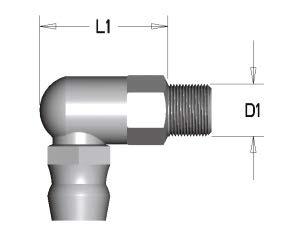
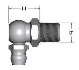
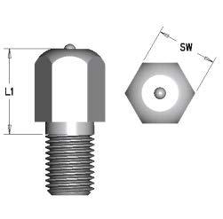
85 400 Series Oil Fittings 400 Series rofile Rail 85


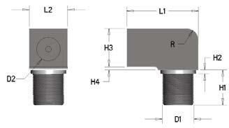
86 400 Series Oil Fittings 86
87 AccuMini Linear Ball Guides Ultra compact, high roll moment capacity Thomson AccuMini Linear Ball Guides offer : Advanced Ball Control reduces friction to provide smooth, quiet operation at high speeds. Full Length Integral Wiper protects critical components from contamination to maximize system life. Gothic Arch rofile provides high roll moment capacity, critical for single rail designs. Engineered olymer Retainer reduces system inertia and noise. Stainless Steel Ball Bearings resist corrosion from harsh environments. art Number Description and Specification AccuMini Assembly # of Carriages er Rail AccuMini Assembly Size: 10, 15, 20 Style AA Description Standard 1 AD 10 AA A H LXXXX Y= (See Note 1 Below) XXX reload Designation A B Length Description Clearance Approx C Options A Armoloy lating LDS Low Drag Seal Mxx Special Option Accuracy Class H = High = recision AccuMini AccuMini Carriage Only AccuMini Carriage Size: 10, 15, 20 Style Description AA Standard CD 10 AA A H XXX reload Designation Description A Clearance B Approx C Options A Armoloy lating LDS Low Drag Seal Mxx Special Option Accuracy Class H = High = recision AccuMini Rail Only RD 10 H LXXXX Y= (See Note 1 Below) AccuMini Rail Size: 10, 15, 20 Length H = High Accuracy Class = recision 1. Y= Distance from end of rail to center of 1st mounting hole 87
88 AccuMini (Miniature Series) Low rofile, Compact Design 1 1. Y dimension will be equal on both ends unless specified by customer. NOTE : The AccuMini linear guide series carriages do not have retained balls. Removing the carriage from the rail without an arbor will result in the balls falling out. AccuMini Linear Guide Series (mm) Size A A1 A2 A3 H H1 H2 B E1 E2 S2 S3 S5 S M2,5 M2,5 3 5, , M4 M4 4, , M5 M5 5,5 9,5 88
89 AccuMini M r, M ro C, Co Dynamic Load and Moment Ratings C = Dynamic load rating M p = Dynamic pitch moment rating M r = Dynamic roll moment rating M y = Dynamic yaw moment rating The dynamic load and moment ratings are based upon a 100 km travel life. In order to compare with bearings rated for 50 km, divide the dynamic capacity of the bearing rated for 50 km by Static Load and Moment Capacities Co = Static load capacity M po = Static pitch moment capacity M ro = Static roll moment capacity M yo = Static yaw moment capacity The static load and moment capacities are the maximum radial load and moment load that should be applied to the bearing while there is no relative motion between the carriage and rail. AccuMini M y, M yo M p, M po Bearing Travel Life Comparison L = (C/F) 3 x 100 km C min = F L 1 ( ) where : where : L = travel life, km C min = minimum required C = dynamic load rating, N dynamic load rating, N F = applied dynamic load, N F = applied dynamic load, N L = required travel life, km Operating arameters Maximum Velocity = 3 m/s Maximum Acceleration = 50 m/s 2 Maximum Temperature = 80 C AccuMini Series (mm) Load N Moment Nm MASS Rating (lbf) Rating (lbfft) Carriage Rail Size N3 N6 X L max C(@100 km) C o M p, M y M po, M yo M r M ro kg kg/m 10 4,5 5, (635) 1,190 (7) (15) (11) (21) 0,045 0, , (1,430) (3,420) (26) (49) (38) (71) 0,141 1, , (2,670) (5,170) 75 (55) 140 (105) 125 (92) 235 (175) 0,345 2,55 Maximum rail length in one section. Multiple sections can be butt jointed together for longer lengths. 89
90 AccuMini Three tolerances describe the accuracy of a rofile Rail bearing: Running arallelism, air Variation, and Assembly Accuracy. These are measured from the rail base to the center of the carriage top (H), and from the rail reference edge to the center of the carriage reference edge (A3). Running arallelism describes the tolerance on H and A3 as a function of axial travel, measured from one carriage down the length of the rail. This is analogous to straightness of travel. As such, parallelism describes attributes of the rail only. Assembly Accuracy describes the tolerance on H and A3 as a function of a carriage rail assembly, measured from the nominal dimensions. air Variation describes tolerance on H and A3 as a function of carriages at the same position on a common rail. air variation describes carriage precision only. The accuracy class selected will partially determine the accuracy of the system. Other factors such as mounting surface flatness and straightness also significantly affect system accuracy. Tolerances Accuracy Class H High recision Assembly Accuracy Tolerance on dimension H and A3 (measured at middle of carriage at any point along rail) ±40 ±20 air Variation Max variation in dimensions H and A3 measured on multiple carriages mounted on the same rail 15 7 (measured at the middle of carriage at same position on rail) Running arallelism See figures above. All values in µm reload Accuracy Combinations Accuracy reload Class Clearance up to 10 µm Light approximately 0,03C 1 B H A B 1. C = Dynamic load capacity of the bearing. Calculations Conversions Operating arameters To determine proper carriage size : C min = F ( L ) 1/3 100 C min = minimum required dynamic load capacity of carriage (N) F = equivalent load on carriage (N) To determine travel life : L = ( C ) F L = normal travel life (km) C = rated dynamic load capacity of carriage (N) 1 lb f = 4,448 N 1 kg f = 9,8 N 1 km = 39,370 inches 1 Nm = lb f ft Maximum Velocity = 3 m/s Maximum Acceleration = 50 m/s 2 Maximum Temperature = 80 C L = required travel life (km) F = equivalent load on carriage (N) 90
91 MicroGuide rofile Rail MicroGuide rofile Rail Two track gothic arch ball groove geometry enables single rail application High Moment Load Capacity for single rail/carriage applications Low rofile Whisper quiet movement Extremely smooth operation High precision accuracy (up to ±0.010mm) 440 stainless steel construction (little or no lubrication required) Industry standard, dropin replacement One piece rail lengths over 1 meter Two styles available (Standard and wide) MicroGuide Sizes: 5mm*, 7mm, 9mm, 12mm, 15mm Note! The Microguide linear guide series carriages do not have retained balls. Removing the carriage from the rail without an arbor will result in the balls falling out. MicroGuide art Numbering Number of Carriages Rail and Carriage Size 5 5 mm* 7 7 mm 9 9 mm mm mm Types TSR Style Z Standard WZ Wide 2 TSR 12 WZ MUUC Material M Stainless Steel (standard) reload Clearance Fit C1 Light reload Seal Configuration UU Lip Seal Standard** Accuracy Normal H High recision Length Custom lengths and configurations *For 5 mm size, there are only 2 mounting holes per carriage. **Seals are not available for 5 mm size. 91
92 MicroGuide rofile Rail MicroGuide rofile Rail TSRZ Standard W3 W1 W2 4 S x d2 L1 L2 L3 h H4 H d3 H1 N W4 W Y X X Standard Lengths of Rail Sizes TSR 7, 9, 12, 15Z TSR 5 Z Standard Lengths X Y Longer lengths may be be supplied as with single buttjoints rail or butt on joints. sizes 7 lease through contact 15. customer service for more information. MicroGuide TSRZ (Standard) Size Assembly Dimensions Carriage Dimensions Rail Dimensions H H1 N W1 W2 W3 L1 L2 L3 Sx W W4 H4 d2 d3 h Y X M2X M2X M3X M3X M3X (1) For 5mm size, there are only 2 mounting holes per carriage. Note All: Dimensions in mm except where noted otherwise. Longer lengths are available with butt joints on sizes 715. Sizes in between standards are available, Y dimensions will be the same unless specified at time of ordering. 92
93 MicroGuide rofile Rail MicroGuide rofile Rail TSRZ Standard Dynamic Load and Moment Ratings C = Dynamic load rating Static Load and Moment Capacities Co = Static load rating M po = Static pitch moment capacity M yo = Static yaw moment capacity M ro = Static roll moment capacity MYO C C O MO MRO Load Capacity (N) Moments (Nm) Mass Size Dynamic C 1 Limit Co 2,3 M O M YO M RO Carriage [kg] Rail [kg/m] Notes: 1. The dynamic load and moment ratings are based upon 50km travel life. 2. The static load and moment capacities are the maximum radial load and moment load that should be applied to the bearing while there is no relative motion between the carriage and rail. 3. The load limit is the maximum load that may be applied to a system. It is important to analyze the application so that peak and/or shock loads do not exceed the load limit. 4. Size 5 does not have end seals. an s required to mount rail. MicroGuide Load/Life Calculations To determine proper carriage size: 50 C min = F ( ) 1/3 L C min = minimum required dynamic load capacity of carriage (N) F = equivalent load on carriage (N) L = required travel life (km) To determine travel life: C L = ( ) 3 F 50 L = normal travel life (km) C = rated dynamic load capacity of carriage (N) F = equivalent load on carriage (N) Operating arameters Maximum Velocity: 3 m/s Maximum Acceleration: 50 m/s 93

94 MicroGuide rofile Rail TSRWZ Wide TSR7WZ L3 W1 d2 L1 L2 S x H H1 W H4 d3 H1 X Y TSR9&12WZ L3 W2 Standard Lengths of Rail Y X Sizes W1 d2 L1 L2 S x Standard Lengths H H1 TSR15WZ H4 d3 H1 L3 W5 W2 X Y W1 Y d2 X L1 L2 S x H H1 H4 d3 H1 MicroGuide TSRWZ Wide Size Assembly Dimensions Carriage Dimensions Rail Dimensions H H1 N W1 W2 L1 L2 L3 Sx W W5 H4 d2 d3 h Y X 7* M4X M2.6X M3X M4X Note: All dimensions in mm except where noted otherwise. Longer lengths are available with butt joints. Sizes in between standards are available, Y dimensions will be the same unless specified at time of ordering. * For 7 mm size, there are only 2 mounting holes per carriage. 94
95 MicroGuide rofile Rail MicroGuide rofile Rail TSRWZ Wide Dynamic Load and Moment Ratings C = Dynamic load rating Static Load and Moment Capacities C o = Static load rating M po = Static pitch moment capacity M yo = Static yaw moment capacity M ro = Static roll moment capacity C C O MO MYO MRO Load Capacity (N) Moments (Nm) Mass Size Dynamic C 1 Limit Co 2,3 M O M YO M RO Carriage [kg] Rail [kg/m] Notes: 1. The dynamic load and moment ratings are based upon 50 km travel life. 2. The static load and moment capacities are the maximum radial load and moment load that should be applied to the bearing while there is no relative motion between the carriage and rail. 3. The load limit is the maximum load that may be applied to a system. It is important to analyze the application so that peak and/or shock loads do not exceed the load limit. MicroGuide Load/Life Calculations To determine proper carriage size: 50 C min = F ( ) 1/3 L C min = minimum required dynamic load capacity of carriage (N) F = equivalent load on carriage (N) L = required travel life (km) To determine travel life: C L = ( ) 3 F 50 L = normal travel life (km) C = rated dynamic load capacity of carriage (N) F = equivalent load on carriage (N) Operating arameters Maximum Velocity: 3 m/s Maximum Acceleration: 50 m/s
96 MicroGuide rofile Rail TSRZ (Standard) Accuracy Tolerance Datum lane C H A D B N Height H Width N Accuracy of each part Dimensional Tolerance air Tolerance Dimensional Tolerance air Tolerance Normal (blank) ± ± TSR5 Z recision ± ± TSR7 Z, TSR9 Z, TSR12 Z & TSR15 Z Normal (blank) ± ± High H ± ± recision ± ± TSRZ (Standard) Running arallelism Running arallelism C and D (µm) Normal High recision Tolerances TSRZ (Standard) Fit Up Series Type, Size and Style TSR5 Z TSR7 Z TSR9 Z TSR12 Z Radial Clearances (µm) clearance fit (blank) light preload C1 0~+1.5 ±2 ±2 ±3 1.5~0 3~0 4~0 6~ Length of Rail L(mm) TSR15 Z ±5 10~0 TSRWZ (Wide) Accuracy Tolerance Datum lane C H A D B N Height H Width N Accuracy of each part Dimensional Tolerance air Tolerance Dimensional Tolerance air Tolerance Normal (blank) ± ± TSR WZ High H ± ± recision ± ± TSRWZ (Wide) Running arallelism Running arallelism C and D (µm) Normal High TSRWZ (Wide) Fit Up Series Type, Size and Style TSR7 WZ TSR9 WZ Radial Clearances (µm) clearance fit (blank) light preload C1 ±2 ±2 3~0 4~0 5 recision TSR12 WZ ±3 6~ Length of Rail L(mm) TSR15 WZ ±5 10~0 96
97 MicroGuide rofile Rail MicroGuide rofile Rail Standard Lengths of Rail Sizes 7 WZ 9 WZ 12 WZ 15 WZ Standard Lengths X Y Load/Life Calculations To determine proper carriage size: 50 C min = F ( ) 1/3 L C min = minimum required dynamic load capacity of carriage (N) F = equivalent load on carriage (N) L = required travel life (km) Conversions 1 lb f = N 1 kg f = 9.8 N To determine travel life: C L = ( ) 3 F 50 L = normal travel life (km) C = rated dynamic load capacity of carriage (N) F = equivalent load on carriage (N) 1 km = 39,370 inches 1 Nm = lbf ft Maximum Travel Speed: V max = 3 m/s Maximum Acceleration: a max = 50 m/s 2 How To Order MicroGuide M for stainless steel (standard) (blank) for clearance fit C1 for light preload (blank) for normal grade H for high grade for precision grade Z for standard style WZ for wide style UU for end seals only (standard) 97
98 TSeries rofile Rail Industry standard dimensions Low cost installation no need for high precision base mounts Reduces mounting surface tolerance requirements allowing 5 times more surface variation compared to steel rail roprietary UChannel design accommodates misalignment from machine base or installation variations Lightweight design and construction Lubrication inlets on both ends of carriage Sold as dimensionally matched rail and carriage assemblies One piece rail length up to 3 meters Aluminum rail with hardened steel ball path insert Class N Normal radial run out accuracy Low drag seal option available Contamination protection with lip seal Speeds up to 3m/s Acceleration up to 50 m/s 2 Multiple carriage design Fourrunner block attachment bolts Corrosion resistance with Armoloy Thin Dense Chrome plating optional TSeries Number of Carriages roduct Type AT TSeries 2 AT 25 A LXXXX LDS Length Size Y= Y Dimension The distance (from the rail end to the first hole) will be equal unless specified Carriage Style A Dimensionally Interchangeable with THK HSR A, B, CA & CB E Dimensionally Interchangeable with THK HSR R & TR F Dimensionally Interchangeable with THK SR W G Dimensionally Interchangeable with THK SR TB Extended Standards A Armoloy LDS Low Drag Seal S... Special Option sequential numbers Note: 1. Sold as assemblies only 2. Carriages are dimensionally matched to rails during assembly 98

99 TSeries Ball rofile Rail Features The Thomson TSeries Ball rofile Rail is lightweight, highly flexible and forgiving an ideal choice for systems with low tolerance mounting surfaces. Materials The Thomson TSeries Ball rofile Rail carriage and rail is produced from high quality aircraft aluminum alloy. The carriage has hardened steel load bearing plates. The rail has a custom ball path insert made of hardened steel. Stringent quality controls are in place to ensure consistency of steel from the source, allowing Thomson to deliver the highest quality product. Lightweight The aluminum carriage and rail dramatically reduce the total weight of the assembly making Thomson TSeries an ideal choice for applications requiring reduced weight or inertia such as airplanes, ships, automobiles, etc. Accuracy As a result of it s high tolerance for alignment errors, the TSeries Ball rofile Rail is available in an N class radial run out only. Easy Installation The Thomson TSeries can be mounted direct to nonmachined bases without sacrificing total operational efficiency or the need for special tools or gauges to ensure proper rail and base straightness. By eliminating the costly machined base and special tools the installation time or machine build time can be cut in half, saving valuable time and money. TSeries Dropin Replacement The Thomson TSeries is designed to industry standard dimensions and rail hole patterns. This means it can be used as a dropin replacement for any conventional all steel profile linear guide in the market today. 99
100 TSeries Carriage Styles Standard Carriage Style A Sizes 20, 25, 35 Dimensionally interchangeable to THK HSR A, B, CA, CB and Thomson 511 A Standard Short Hole Spacing Style G Sizes 20, 25, 35 Dimensionally interchangeable to THK SR TB Narrow Carriage Style E Sizes 20, 25, 35 Dimensionally interchangeable to THK HSR R and TR and Thomson 511 E Narrow High Style F Sizes 20, 25, 35 Dimensionally interchangeable to THK SR W 100

101 TSeries Ball rofile Rail Style A and G H H 1 N 1 N 5 S 2 Thread Lubrication Access Both Ends S 1 Screw Size H 2 N 6 Y X S 3 Screw Size S 6 A 3 A 2 S 5 A 1 A Will be equal on both ends, unless otherwise specified. Supplied Lubrication Fittings M6 Tapered Thread L E 2 B 9 45 M6 Tapered Thread 15 TSeries E 1 TSeries rofile Rail Standard High A Style Size A A1 A2 A3 H H1 H2 B E1 E2 S1 S2 S3 S5 S6 N1 N5 N6 X L max M5 M6 M , M6 M8 M M8 M10 M All dimensions in mm unless shown otherwise TSeries rofile Rail Standard G Style Size A A1 A2 A3 H H1 H2 B E1 E2 S1 S2 S3 S5 S6 N1 N5 N6 X L max M5 M6 M M6 M8 M M8 M10 M All dimensions in mm unless shown otherwise 101
102 TSeries Ball rofile Rail Style A and G Dynamic Load Rating C = Dynamic load rating The dynamic load rating is based upon a 100 km travel life. In order to compare with bearings rated for 50 km, divide the dynamic rating of the bearing rated for 50 km by Static Load Capacity C o = Static load capacity The static load capacity is the maximum radial load that should be applied to the bearing while there is no relative motion between the carriage and rail. F s F c F t Load Ratings N (Ibf) Mass Carriage Rail Size Style C (@100km) C o kg kg/m 20 A 9000 (2025) (2475) G 25 A (2925) (3375) G 35 A (5620) (6295) G Dynamic Load Load Rating Limit F c C C F t C 0.6C F s C 0.6C Bearing Travel Life Calculation L = (C/F) 3 x 100 km where: L = travel life, km C = dynamic load rating, N F = applied dynamic load, N Operating arameters Maximum Velocity = 3 m/s Maximum Acceleration = 50 m/s2 Maximum Temperature = 80 C 102
103 TSeries Ball rofile Rail Style E and F N 5 A S 2 Thread x N3 Deep H H 1 Lubrication Access Both Ends X S 3 Screw Size Y S 6 A 3 A 2 A 1 H 2 A 4 N 6 S 5 Will be equal on both ends, unless otherwise specified. Supplied Lubrication Fittings L E 2 B M6 Tapered Thread M6 Tapered Thread TSeries E 1 TSeries rofile Rail Narrow E Style Size A A1 A2 A3 A4 H H1 H2 B E1 E2 S2 S3 S5 S6 N3 N5 N6 X L max M5 M M6 M M8 M All dimensions in mm unless shown otherwise TSeries rofile Rail Narrow High F Style Size A A1 A2 A3 A4 H H1 H2 B E1 E2 S2 S3 S5 S6 N3 N5 N6 X L max M5 M M6 M M8 M All dimensions in mm unless shown otherwise 103
104 TSeries Ball rofile Rail Style E and F Dynamic Load Rating C = Dynamic load rating The dynamic load rating is based upon a 100 km travel life. In order to compare with bearings rated for 50 km, divide the dynamic rating of the bearing rated for 50 km by Static Load Capacity C o = Static load capacity The static load capacity is the maximum radial load that should be applied to the bearing while there is no relative motion between the carriage and rail. F s F c F t Load Ratings N (Ibf) Mass Carriage Rail Size Style C (@100km) C o kg kg/m 20 E 9000 (2025) (2475) F 25 E (2925) (3375) F 35 E (5620) (6295) F Dynamic Load Load Rating Limit F c C C F t C 0.6C F s C 0.6C Bearing Travel Life Calculation L = (C/F) 3 x 100 km where: L = travel life, km C = dynamic load rating, N F = applied dynamic load, N Operating arameters Maximum Velocity = 3 m/s Maximum Acceleration = 50 m/s2 Maximum Temperature = 80 C 104
105 NOTES : TSeries 105
106 Installation Guidelines Figure 1 1 Table 1. arallelism Between Multiple Rails, mm reload Bearing Type Clearance 0,03 C 0,08 C 0,13 C 500 Series Ball Linear Guide Series Roller Linear Guide AccuMini Linear Guide TSeries * Linear Guide Series Ball Linear Guide Where C = Dynamic Load Capacity Surface reparation rofilerail bearings are generally mounted to structures that are inherently stiffer than the rail. For this reason, the bearings tend to assume the orientation of the surfaces to which they are fastened, through bearing deflection. When a deflection is imposed upon a bearing, especially a preloaded one, resultant forces occur. These forces are transferred to the rolling elements and races, potentially resulting in an increase in system friction and a decrease in system resolution, precision and life. Various sources can contribute to the overall error of the mounting surfaces. These include the surface flatness of the base surfaces, the location and parallelism of the reference surfaces, and the attendant errors of the bearing as described within the accuracy classes. The surfaces that contact the base and reference edges may be milled, scraped, ground, or prepared by any other method that will produce a flat mounting surface free of inconsistencies, which would tend to distort or skew the bearing. A simple stone may be used to remove high spots. Dirt and debris should be cleaned off, as they could contribute to the inaccuracies. Associated with preload is a slight potential concavity of the carriage top surface. The preload is established when all the carriage screws are affixed to a planar surface, flattening the carriage base. Deviations affecting the planarity of the carriage mounting surface could result in a preload change. Mounting Tolerances The tolerances found in Tables 1 3 are intended to provide an installation for which the associated derating is negligible. These specifications are based upon the assumption that the structures of the application are infinitely rigid and are of consideration for the bearing reactions only. Rail arallelism (See Figure 1) A variation in the distance between the rails will induce a shear or side load on the bearings. In order to minimize the effect of this shear load, tolerances for rail reference edge parallelism may be found in Table
107 Installation Guidelines Figure 2 a Table 2. Allowable Vertical Offsets Between Rails (S1/a), inch reload Bearing Type Clearance 0.03 C 0.08 C 0.13 C 500 Series Ball , Series Roller AccuMini Linear Guide TSeries Linear Guide Series 15, 20 & Series Series Series Series Where C = Dynamic Load Capacity Figure 3 Figure 4 S 1 Rail Vertical Offset (See Figure 2) A vertical offset of the rails across the axis will induce a roll moment onto the carriages. To minimize the effect of this roll moment, tolerances for the vertical offset may be found in Table 2. This tolerance describes the attributes of the mounting surface, perpen dicular to the rail axis. Vertical Carriage Offset (See Figure 3) A vertical offset between fore and aft carriages will induce a pitch moment on the bearings. Lateral Carriage Offset (See Figure 4) A lateral offset of the carriage reference edges will induce a yaw moment. In order to minimize the effects of these pitch and yaw moments, tolerances may be found in Table 3. This tolerance describes the attributes of the mounting surface parallel to the rail axis, and the reference edge straightness. NOTE : All mounting tolerances should be inclusive of the H and A3 tolerances. Thus, a lower accuracy class bearing may require a more accurate installation. Mounting Hole Tolerances The positional tolerance between the through holes in the rails is 0.5 mm. The positional tolerance of the first rail mounting hole dimensioned from the datum end (called the Ydimension ) is ±1.0 mm. S 2 b The overall rail length tolerance is ±2.0 mm. The positional tolerance between the mounting holes in the carriages is 0.2 mm. Installation Guide Table 3. Allowable Carriage Offsets (S2/b) reload Bearing Type Clearance 0.03 C 0.08 C 0.13 C 500 Series (All) 0, , , , Series 15 & Series Series Series Series Series Where C=Dynamic Load Capacity Reference Edge Specifications The maximum shoulder heights and corner radii are listed in Table 4. TSeries Linear Guide 0,
108 Installation Guidelines Table 4. Shoulder heights and corner radii, mm Guide Type Rail Carriage h1 max r1 max h2 r2 max 500 Series Ball Linear Guide Series Roller Linear Guide AccuMini Linear Guide TSeries * Linear Guide Series Ball Linear Guide Table 5. Recommended Bolt Tightening Torque, Nm Bolt Size Class 8.8 Class 12.9 M M M M M M M M M Installation rocedure Clean and inspect all mating surfaces for burrs, nicks, dirt, etc. A simple stone can be used to remove minor imperfections in the mounting surfaces. Note : TSeries is not as sensitive to imperfections of the mounting surface. Rail Mounting 1. Carefully place the rail on the mounting surface. 2. Insert screws into the mounting holes and tighten lightly. 3. Clamp the reference edge of the rail against a locating edge on the mounting surface. The locating edge can be a machined reference edge, a straight edge, a row of dowels or keys, or some other edge which the rail can be clamped against. It should be straight, either within the mounting tolerances shown in Table 3 or according to the application requirements, whichever is tighter. 4. Starting from the center of the rail moving outwards, tighten each screw to the recommended tightening torque in Table If parallel rails are to be used, one of the following methods may be employed to obtain the parallelism recommended in Table 1 : a. two parallel locating edges b. a gage block or parallel between the rails c. the use of the top plate with the carriages mounted, to locate or float the second rail into place. 6. Repeat steps 1 4 to install the second rail. 7. Insert a rail plug into each counterbore in the rail. Carefully tap rail plugs into place using a soft material such as brass or wood. When properly installed, the rail plugs should be flush with the top surface of the rail. Do not countersink the rail plugs. Note : Rail plugs are available and are shipped with all rails except for the AccuMini Linear Guide size If desired, rail tape can then be applied to the top of the rail. For sizes 35 and below, the rail tape may be used without the rail plugs
109 Installation Guidelines Figure 5. Shoulder Heights and Corner Radii h 2 r 2 h 1 r 1 Figure 6. Butt jointed rails Joint Indicator Reference Edge Joint A A Z X (TY) Figure 7. Recommended Tightening Sequence Butt Joints For rails longer than the longest length available in one piece, a butt joint is required. A butt joint is formed by butting the end of two matched rails together. The ends of rails to be butt jointed are specially machined and marked with same letter (A, B, C, etc.). We strongly recommend the use of a locating edge when using butt jointed rails. This will ensure proper alignment of the raceways across the joint. 500 Series Ball, Roller and 400 Series linear guide rails, the mounting hole spacing across the joint, Z, will be equal to the standard mounting hole spacing, X. Once mounted, a gap between the ends of the butt jointed rails of 0.5 mm or less is acceptable. Carriage Mounting 1. Carefully place the table top on the carriages. 2. Insert the screws into the mounting holes and tighten lightly. 3. Clamp the reference edge of the carriages to locating edges under the top plate. Note : This is only required if the location of the center of the top plate is critical to the application, or if the top plate is being used to position a second rail parallel. 4. Tighten each screw to the recommended tightening torque in Table 5. For carriages with six mounting screws, the tightening sequence shown in Figure 7 is recommended. 5. Lubricate bearings. Note : Extreme care should be taken when mounting the carriages to the rails. Forcing a carriage onto a rail can knock out rolling elements and/or damage the carriage and rail. Installation Guide For large side forces, hard mounting is recommended to resist any translation. Some methods for hard mounting are the use of tapered gibs, retaining plates, or set screws in combination with machined reference edges. Other methods include the use of an epoxy/replicating material, dowels, and keys. Upon request, carriages and rails can be special machined to accommodate dowels or keys. Consult the factory for details

110 rofile Rail Engineering Guide Table of Contents Description...age rofile Rail Selection Technology Overview Sizing & Defining Guide Characteristics Applied Loading Calculations Need a quote or have a question about an application? Contact us in North America at: hone: Fax: thomson@thomsonlinear.com Load Ratings : Rolling Element Guides Sliding Contact Guides reloading & Linear Guide Deflection Actuation Force Lubrication Bellow Cover Length Calculations Butt Joint Faxback Worksheet Conversion Table
111 rofile Rail Selection The selection of a linear guide can greatly affect machine performance and overall cost. In order to meet the wide variety of demands created by today s applications, proper selection from a broad range of linear guides is required. For example, selecting a guide with too much rigidity will decrease the allowable installation tolerances, therefore, greatly increasing surface preparation costs. If the mounting surface is not prepared properly, the guide will run rough, and need to be replaced more frequently due to an unexpected reduction in travel life. Consider all criteria appropriate for the application. Selection criteria include : Technology Overview The performance of a linear guide is based upon contact type, rolling element type, inner race geometry (Round Rail and rofile Rail), and other characteristics such as selfaligning capabilities. It is important to recognize that the options available for each characteristic have performance attributes. The selection process should be focused on matching these attributes with the most critical requirements of the application. The following technology guidelines can be used to assist in selecting the most appropriate type of profile rail. For a detailed application analysis, contact the Thomson Customer Support or your local Thomson distributor. Rigidity Travel accuracy Travel life Smoothness of travel Speed & Acceleration Envelope Environment Cost of roduct Cost of Installation Cost of Replacement Selection of the most appropriate type of guide, should be based on quantitative / qualitative requirements and ranking by importance of the above selection criteria, as well as the following guidelines for the technology available. Engineering Guide 111
112 Sizing & Defining Guide Characteristics The following 9 step procedure can be used to select the characteristics necessary to generate the appropriate part number : 1. Determine the load on the most heavily loaded carriage or bearing (see Applied Loading Calculations). Multiply by a safety factor if desired in your application. 2. Determine the minimum required travel life for the application based on the intended duty cycle. 3. Calculate the Minimum Required Dynamic Load Rating, C min. 4. Select the size which offers the load rating, C, equal to or greater than the minimum required dynamic load rating, C min. Also, consider Dynamic Load Limit and Static Capacities. 5. If the guide selected offers various preload levels, select a preload based upon the allowable bearing deflection. Contact the factory for detailed deflection information. Some carriage or bearing Deflection Charts are provided in this catalog. 6. If the guide selected offers various accuracy classes, select an accuracy class based upon the required travel accuracy. 7. Determine the need for accessories or options. 8. Calculate the guide length based upon the stroke and platten length. Remember to include additional length of accessories (i.e. selflubricating option) and the stroke reduction caused by the use of bellows, if applicable. 9. Once the above characteristics have been determined, assign the appropriate part number based on the part numbering instructions located in the catalog section corresponding to the linear guide selected. Choosing a higher preload level will reduce the allowable installation tolerances. For this reason, the minimum preload which meets the applications requirements should be selected. If the highest preload level does not meet the deflection requirements, a larger size may be required
113 Applied Loading Calculations The majority of applications utilize a four carriage or bearing and two rail design for stability. Shown are four typical configurations and calculations for the resultant loads applied to each bearing. Resultant loads are divided into a horizontal and a vertical components, which represent the static or constant velocity condition and account for gravity but not acceleration. Use the appropriate configuration to determine the hori zontal and vertical components of the resultant applied load on the most heavily loaded carriage or bearing. These values will be referred to henceforth as FH & FV, respectively. Terms : d 0 = distance between centerlines of carriages or bearings (in) or (mm) d = 1 distance between centerlines of rails (in) or (mm) d 2 = distance from centerline of carriage or bearing to load action point (in) or (mm) d 3 = distance from centerline of carriage or bearing to load action point (in) or (mm) W = Applied Load (lbf) or (N) FNH = Horizontal component of resultant applied load with respect to each carriage or bearing (lbf) or (N) FNV = Vertical component of resultant applied load with respect to each carriage or bearing (lbf) or (N) Reminder: Be sure to use consistent units (English or metric). Be sure to use the appropriate sign (positive or negative). A negative number is used when the actual force is in the opposite direction represented by the arrow. ( F 1v = W + W d 2 W d d 0 2 d 1 ( F 2v = W W d 2 W d d 0 2 d 1 ( F 3v = W W d 2 + W d3 4 2 d 0 2 d 1 ( F 4v = W + W d 2 + W d d 0 2 d 1 ( ( ( ( ( ( ( ( ( ( ( ( Horizontal Application I At the time of movement with uniform velocity or at the time of stop. ( F 1v = W + W d 2 W d d 0 2 d 1 ( F 2v = W W d 2 W d d 0 2 d 1 ( F 3v = W W d 2 + W d3 4 2 d 0 2 d 1 ( F 4v = W + W d 2 + W d d 0 2 d 1 ( ( ( ( ( ( ( ( ( ( ( ( Horizontal Application II At the time of movement with uniform velocity or at the time of stop. F 1v = F 2v = F 3v = F 4v = + W d 3 2 d 1 W d 3 2 d 1 F 1H = F 4H = W + W d d 0 F 1H = F 4H = W W d d 0 ( ( ( ( ( ( ( ( Side Mounted Application At the time of movement with uniform velocity or at the time of stop. F 1v = F 4v = ( W d 2 2 d 0 ( d2 F 3v = F 4v = + ( W d 2 2 d 0 F 1H = F 2H = F 3H = F 4H = W d3 2 d 0 ( F1H d0 F2H F1v F4v d1 F2v W d3 Engineering Guide Vertical Application At the time of movement with uniform velocity or at the time of stop. At the time of start & stop, the load varies because of inertia
114 Equivalent Applied Load An equivalent load is used to consolidate applied load components into one value which can later be used to calculate the minimum required load rating and the expected life of the carriage / bearing selected. F V For rofilerail* Carriages & Closed RoundRail* Bearings : F EQ = F H + F V F H F EQ = Equivalent Load F H = Horizontal Component of Resultant Applied Load F V = Vertical Component of Resultant Applied Load For Single Carriage or Single Rail Configurations : F EQ = F H + F V + (M / M C ) x C M = Applied Moment Load M C = Dynamic Moment Capacity of Bearing C = Dynamic Load Capacity of Bearing For reloaded Carriages [ Only when F EQ < (3 x Fp) ] : Even with no external load applied, a preloaded bearing has a load on the races. A load greater than the externally applied load is present within a bearing with an externally applied load less than the preload end point. In order to calculate the loads on the load sets, the following formulae may be employed : F EQ = F p (F H + F V ) F p = Initial reload Force (i.e., for B reload Designation F p =.03 x C) Before calculating F EQ, make sure that neither F H or F V exceeds the Dynamic Load Limit of the guide intended for use. (See Dynamic Load Limit on age 102). The 0.6 value used accounts for a derating factor of the capacity during tensile loading. Therefore, when calculating expected life based on F EQ, the Full Dynamic Load Rating (C) may be used
115 Mean Dynamic Load In applications with loads of varying magnitude, a mean dynamic load should be calculated. Where : F EQ1 F EQn = equivalent dynamic load for distances d1 through dn D = total distance of stroke = d1+d2 +dm = 3 (linear guides w/ball Type Rolling Elements) 10/3 (linear guides w/roller Type Rolling Elements) Load Ratings for Rolling Element Guides Dynamic Load Rating, C, and Travel Life The dynamic load rating, C, is the load at which when applied will yield the rated travel life. The rated travel life, Lr, for most linear guides is 100 km for metric products and 4 million inches for inch products (the rated travel life is listed on the page with the dynamic load rating). For a given applied load,, the dynamic load rating and rated travel life are used to calculate the travel life using the following load / life equation : L = (C/F EQ ) n x L r Where : L = calculated travel life C = dynamic load rating F EQ = equivalent applied load n = 3 for ball guides, 10/3 for roller guides = rated travel life L r Some manufacturers dynamic load ratings are based upon a 50 km life. To compare dynamic load ratings for guides with a 50 km rated life with a 100 km life, divide the 50 km dynamic load rating by C 100 km = C 50 km / 1.26 Some types of linear guides do not have the same dynamic load rating in all directions. The dynamic load rating for orthogonal load directions is shown as a percentage of C. It is not necessary to use this percentage of C in the load / life equation provided that the Equivalent Applied Load Section has been adhered to, because the calculations for equivalent applied load already account for it. Engineering Guide 115
116 Calculating the Minimum Required Dynamic Load Rating, C min The load / life equation above can be rewritten to calculate the minimum required dynamic load rating which should be selected for a given applied load and minimum required travel life : C min = (L m / L r) 1 / n Where : C min = minimum required dynamic load rating = applied load L m = minimum required travel life L r = rated travel life n = 3 for ball guides, 10/3 for roller guides Note : Check that the applied load, does not exceed the dynamic load limit. Dynamic Load Limit The dynamic load limit, is the maximum load which should be applied to the carriage / pillowblock. In some cases, the dynamic load capacity equals the dynamic load rating. In others, a limit shown as a percentage of the dynamic load rating is the maximum load which should be applied. A dynamic load limit less than the dynamic load rating does not derate the life of the guide. Static Capacities The static capacities are the maximum loads that should be applied to the bearing while there is no relative motion between the rolling elements and the raceways. The value C 0 is the static load capacity for a radial load acting orthogonal to the axis of travel. The values M OL and M OQ are the static roll, pitch, and yaw moment capacities. It is important to analyze the application so that shock loads do not exceed these capacities. Exceeding these capacities may permanently deform the rolling elements and raceways. This type of damage will be realized by an increase in friction, noise, and vibration, as well as by an increase in clearance between the carriage and the rail. For systems experiencing repetitive shock loading less than the static load capacities, the bearing life should be determined by means of fatigue calculations
117 reloading & Linear Guide Deflection Deflection Curves reload A preloaded bearing has a condition of interference between the races of the rails, the rolling elements, and the races of the carriage. Curves are available for Thomson 500 Series at: reloading decreases the deflection due to external loads. This occurs because the contact reaction has already developed, eliminating much of the initial nonlinear deflection associated with rolling elements. The rolling element reactions within a preloaded bearing may be considered as having two components. One com ponent acts in the direction of external load, and one component acts in the opposing direction in order to maintain static equilibrium. These components are referred to as load sets. As external load is applied, one load set increases in load, as the opposite load set decreases in load. At some point, the load on the decreasing load set becomes zero. This point, at which the preload is relieved, is called the preload end point. reload end typically occurs when the external load is approximately three times the preload. reload end point : F ext = 3F p where: F ext = externally applied load F p = preload By definition, a preloaded bearing, loaded beyond the preload endpoint, has the same deflection characteristics of an unpreloaded bearing externally loaded to that percentage of its dynamic load capacity. A preload level is assigned as a percentage of the dynamic load capacity of the bearing. Example Applications reload Clearance.03C.08.13C Conditions 1. weak impact 2. 2 rails in pair 3. low accuracy 4. small resistance 1. cantilever 2. single rail 3. light load 4. high accuracy 1. strong impact 2. strong vibration 3. heavy machining Engineering Guide Applications 1. welding machine 2. chopping machine 3. feeding mechanism 4. tool change mechanism 5. ordinary XY table 1. NC lathe 2. EDM 3. precise XY table 4. ordinary Zaxis 5. industrial robot 6. CB punching 1. machining centre 2. NC lathe and milling machine 3. feeding axis of grinder 4. tool feeding axis 117
118 Actuation Force The force required to actuate a linear guide (FA) has four basic components : 1. Frictional resistance (F f ) 2. Intrinsic resistance (D int ) 3. Inertia of the moving components (F inertia ) 4. Viscose drag of the lubrication (D l ) F A = F f + D int + F inertia + D l Frictional Resistance Rolling Element Guides Friction occurs in rolling element guides as a result of slipping of the rolling elements on the raceways. The frictional resistance can be calculated by means of the following equation : F f = µ x F i Where : µ = coefficient of friction (dependent upon type of guide type, rolling element type and load) F i = force internal to the linear guide The following table lists the coefficient of friction for different types of guides : Ball Type rofile Rail Roller Type The value for the coefficient of friction is a function of the applied load. The coefficient of friction increases as load is applied. This is due to the increased contact area between the rolling elements and races. The force internal to the linear guide is equal to the external force (F ext ) applied to the linear guide in nonpreloaded guides, and preloaded guides loaded beyond 3 times the preload value (F p ). F i = F ext For preloaded guides loaded below a level of 3 times the preload value (F p ), the internal force can be approximated with the following equation : F i = 2F p + 1/3 F ext 118
119 Intrinsic Resistance The intrinsic resistance is the measured actuation force required to move the guide at a constant velocity, without lubrication, regardless of load. It consists of the seal drag (larger component) and force required to circulate the rolling elements (smaller component). The intrinsic resis tance can be assumed to be a constant for linear guides carrying more than 5% of their dynamic load rating (C). For guides loaded below that value, the force required to circulate the rolling elements will increase. The following chart shows the intrinsic resistance, D int, for different types and sizes of linear guides. Inertia of Moving Components Inertia is directly related to the mass and acceleration by the following equation : F inertia = Ma Viscose Drag of the Lubrication The viscose drag of the lubricant is dependent upon the viscosity of the lubricant selected. reload reload of the assembly has an effect on intrinsic resistance, the greater the preload the greater the intrinsic resistance to move the guide. 500 Series Ball rofile Rail Size Carriage Style Carriage Style A, C B, D D int (N) D int (N) D int (N) reload 0.03C 0.13C 0.03C 0.13C Values for lubricant oil VG 68, speed 0.1 m/s 500 Series Roller rofile Rail Size Carriage Style Carriage Style A, C B, D D int (N) D int (N) Value for 0.13 C reload, lubricant oil VG68, speed 0.1 m/s Engineering Guide 119
120 Lubrication Lubrication provides protection against wear, corrosion, heat, and friction. Applicationspecific variables, such as load, speed, and environmental conditions, determine the most suitable lubricant and lubrication schedule for that specific application. Thomson s general lubricant recommendation for linear guides is a grade 2 grease. A maximum of one year or 100 km, whichever comes first, between applications of lubricant is recommended. A grease with an extreme pressure additive should be used for guides loaded beyond 50 of their dynamic load rating (C). Oil can also be used and is recommended in applications where the bearings experience high speeds. Use the uppermost lubrication port on oillubricated bearings that are vertically oriented to ensure gravityassisted lubricant dispersal. Linear guide products are supplied with a light coating of preservative oil. This preservative oil is for storage purposes only and is not recommended as lubrication for the bearing. Lubrication rocedure For best lubrication dispersal, the carriage should be moved on the rail while applying lubricant to ensure circulation to all internal bearing surfaces. It is not possible to over lubricate the bearings, as excess lubricant will merely exit the carriage under the seals. Recommended initial volumes of lubricant for 500 Series bearings are shown in the tables. The recommended volume for relubrication is 1/2 the initial volume. Short Stroke In the case of a stroke less than 2X s the carriage length, two lubrication connections are recommended, one at each end to ensure adequate lubrication to the entire ball or roller track. Oil Reservoir The oil reservoir is supplied from the factory ready for installation (filled with oil). Relubrication is dependent upon many factors such as speeds, temperature, cleanliness, etc. The following is a guideline for relubrication. (It is recommended to relubricate every 12 months.) Initial Grease Volume for 500 Series Ball Bearings Size Carriage Style Carriage Style A, C, E (cm 3 ) B, D, F (cm 3 ) Initial Grease Volume for 500 Series Roller Bearings Size Carriage Style Carriage Style A, C (cm 3 ) B, D (cm 3 ) Oil Reservoir Refill Quantity Size 500 Series Ball 500 Series Roller 531OW Oil 532OW Oil Qty (cm 3 ) (cm 3 ) Relubrication Size Travel Distance 2500 km 5000 km The oil reservoir is filled in the factory with Kluber Lamora D220 oil. If relubricating with different oil it is the responsibility of the user to determine oil compatibility. The recommended refill quantity is shown in the table

121 SelfLubricating rofile Rail Lube Block The selflubricating Lube Block option offers maintenance free operation and enhanced protection for a broad range of applications. It offers : Reduced system cost by eliminating the need for designing, purchasing, and installing expensive lubrication systems. Environmentally friendly operation. Increased bearing life by offering enhanced protection. Design The selflubricating option utilizes selflubricating attachments at both ends of the carriage and includes an initial E2 grease pack of the carriage. The selflubricating attachments consist of a section of oil saturated polymer actively compressed by a contact spring, inside a double lip seal. A contact spring assures continuous contact with the rail, releasing oil as the carriage moves. This ensures a film of lubricant between the rolling elements and races. When the carriage is at rest, oil is reabsorbed by the polymer. erformance The design has incorporated a proven oilsaturated polymer used for over 10 years to lubricate radial bearings. This method of lubrication has a successful track record in applications ranging from food processing to automotive assembly. The graph below shows the theoretical L10 life expectancy and actual test results for the following two methods of lubrication : 1. Bearing with selflubricating attachments only. 2. Bearing initially packed with E2 grease only. Load (ercent of Dynamic Load Rating) 100% 90% 80% 70% 60% 50% 40% 30% 20% 10% Life Expectancy with SelfLubricating Option and Initial Grease ack vs. L10 Theoretical Life L10 Life Expectancy Lubricated with SelfLubrication Attachments Initially Lubricated with E2 Grease Life (km) Testing arameters Stroke : 500 mm Speed : 0,6 m/s This chart illustrates how using the selflubricating option, which combines the selflubricating attachments and initial grease pack, will enable the bearing to achieve the L10 life expectancy under all loading condition. Note that for travel lives exceeding 30,000 km, recharging or replacing of the selflubricating polymer is recommended. Engineering Guide 121
Profile Rail Linear Guides 500 Series Ball Profile Rail, 500 Series Roller Profile Rail, 400 Series Profile Rail, AccuMini, MicroGuide, T-Series
 Toll Free hone (877) SERVO98 rofile Rail Linear Guides 500 Series Ball rofile Rail, 500 Series Roller rofile Rail, 400 Series rofile Rail, AccuMini, MicroGuide, TSeries Thomson the Choice for Optimized
Profile Rail Linear Guides. 500 Series Ball Profile Rail 500 Series Roller Profile Rail AccuMini MicroGuide T-Series. Linear Motion. Optimized.
 rofile Rail Linear Guides 500 Series Ball rofile Rail 500 Series Roller rofile Rail AccuMini MicroGuide TSeries A DANAHER MOTION COMANY Linear Motion. Optimized. Thomson Linear Motion. Optimized. Linear
Profile Rail Linear Guides
 www.thomsonlinear.com rofile Rail Linear Guides 500 Series Ball rofile Rail, 500 Series Roller rofile Rail, 400 Series rofile Rail, AccuMini, MicroGuide, TSeries Thomson the Choice for Optimized Motion
Linear Motion. Optimized.
 Thomson - Linear Motion. Optimized. Linear Motion. Optimized. Often the ideal design solution is not about finding the fastest, sturdiest, most accurate or even the least expensive option. Rather, the
Ball Rail Systems RE / The Drive & Control Company
 Ball Rail Systems RE 82 202/2002-12 The Drive & Control Company Rexroth Linear Motion Technology Ball Rail Systems Roller Rail Systems Standard Ball Rail Systems Super Ball Rail Systems Ball Rail Systems
400 Series Profile Rail Linear Guides
 400 Series Profile inear uides Transport grade ball profile rail system www.thomsonlinear.com EECTROMTE Features and enefits The 400 Series Profile inear uide is the newest addition to the Thomson inear
Linear Motion Systems
 Linear Motion Systems Thomson - the Choice for Optimized Motion Solutions Often the ideal design solution is not about finding the fastest, sturdiest, most accurate or even the least expensive option.
Linear Motion Systems Toll Free Phone: Toll Free Fax:
 Linear Motion Systems Thomson - the Choice for Optimized Motion Solutions Often the ideal design solution is not about finding the fastest, sturdiest, most accurate or even the least expensive option.
Linear Motion Systems
 Linear Motion Systems www.thomsonlinear.com Thomson - the Choice for Optimized Motion Solutions Often the ideal design solution is not about finding the fastest, sturdiest, most accurate or even the least
Profi le rail guides LLR
 Profi le rail guides LLR Content The SKF brand now stands for more than ever before, and means more to you as a valued customer. While SKF maintains its leadership as the hallmark of quality bearings throughout
R310EN 2302 ( ) The Drive & Control Company
 The Drive & Control Company") R31EN 232 (26.4) The Drive & Control Company Bosch Rexroth AG Linear Motion and Assembly Technologies Ball Rail Systems Linear Bushings and Shafts Ball Screw Drives Linear Motion Systems Basic Mechanical
R31EN 232 (26.4) The Drive & Control Company Bosch Rexroth AG Linear Motion and Assembly Technologies Ball Rail Systems Linear Bushings and Shafts Ball Screw Drives Linear Motion Systems Basic Mechanical
R310EN 2211 ( ) The Drive & Control Company
 The Drive & Control Company") eline Ball Rail Systems R310EN 2211 (2006.04) The Drive & Control Company Bosch Rexroth AG Linear Motion and Assembly Technologies Ball Rail Systems Roller Rail Systems Linear Bushings and Shafts Ball
eline Ball Rail Systems R310EN 2211 (2006.04) The Drive & Control Company Bosch Rexroth AG Linear Motion and Assembly Technologies Ball Rail Systems Roller Rail Systems Linear Bushings and Shafts Ball
Courtesy of CMA/Flodyne/Hydradyne Motion Control Hydraulic Pneumatic Electrical Mechanical (800) TRUE Planetary Gearheads
 TRUE Planetary Gearheads") Courtesy of CMA/Flodyne/Hydradyne Motion Control Hydraulic Pneumatic Electrical Mechanical (800) 426-5480 www.cmafh.com TRUE Planetary s Courtesy of CMA/Flodyne/Hydradyne Motion Control Hydraulic Pneumatic
Courtesy of CMA/Flodyne/Hydradyne Motion Control Hydraulic Pneumatic Electrical Mechanical (800) 426-5480 www.cmafh.com TRUE Planetary s Courtesy of CMA/Flodyne/Hydradyne Motion Control Hydraulic Pneumatic
The Classification Chart of PMI Linear Guideways
 1 The Characteristics of MI s The Classification Chart of MI s 2 (1) igh positioning accuracy, high repeatability The MI linear guideway is a design of rolling motion with a low friction coefficient, and
Thomson RoundRail Linear Guides and Components
 Thomson RoundRail Linear Guides and Components Selection Guide for Inch and Metric Linear Ball Bushing Bearings, 60 Case Shafting and RoundRail Linear Guides Thomson - Linear Motion. Optimized. Often the
Q&A Session for Advanced Linear Bearings and Guides 201 : Troubleshooting for Design Engineers
 Q&A Session for Advanced Linear Bearings and Guides 201 : Troubleshooting for Design Engineers Date: April 22, 2009 Q: We are currently looking into using Self Lubricating Bushings in a high-load Off-
T-Series Ball Profile Rail TECHNICAL BULLETIN
 T-Series Ball Profile Rail TECHNICAL BULLETIN T-Series Profile Rail Industry standard dimensions Low cost installation no need for high precision base mounts Approximately 5 times more forgiving than all
Thomson RoundRail Linear Guides and Components
 Thomson RoundRail Linear Guides and Components Selection Guide for Inch and Metric Linear Ball Bushing Bearings, Shafting and RoundRail Linear Guides Linear Motion. Optimized. Thomson - Linear Motion.
NEW. Linear Ball Bushing Bearings and 60 Case Shafting. Profile Rail Linear Guides
 Linear Ball Bushing Bearings and 60 Case Shafting Thomson invented the ball bushing bearing over 60 years ago and has since been the recognized leader in this field. Our linear products provide low friction,
Linear Actuator with Ball Screw Series OSP-E..S. Contents Description Overview Technical Data Dimensions 89
 Linear Actuator with Ball Screw Series OSP-E..S Contents Description Page Overview 79-82 Technical Data 83-88 Dimensions 89 79 The System Concept ELECTRIC LINEAR ACTUATOR FOR HIGH ACCURACY APPLICATIONS
Linear Actuator with Ball Screw Series OSP-E..S. Contents Description Overview Technical Data Dimensions 79
 Linear Actuator with Ball Screw Series OSP-E..S Contents Description Page Overview 71-74 Technical Data 75-78 Dimensions 79 71 The System Concept ELECTRIC LINEAR ACTUATOR FOR HIGH ACCURACY APPLICATIONS
LINEAR SLIDES RECISION NDUSTRIAL OMPONENTS DESIGN. Phone: FAX:
 R RECISION NDUSTRIAL OMPONENTS R LINEAR SLIDES 2. 4. 3. 1. Ball Slides 2. X, X-Y, X-Y-Z Positioners with Micrometers 3. Rails 4. Crossed Roller Slides 1. 2-1 TECHNICAL SECTION Typical coefficient of friction
TRUE Planetary Gearheads
 TRUE Planetary Gearheads Danaher Motion - Helping you build a better machine, faster Danaher Corporation combined over 3 industry-leading brands such as Kollmorgen, Thomson, Dover, Pacific Scientific,
Ballscrews / Linear Guideway General Catalog
 Ballscrews / inear Guideway General Catalog inear Guideway 2 Introduction of ach Series 2. eavy oad Type, MSA Series A. Construction Upper Retainer Carriage nd Seal nd Cap Rail Grease Nipple Ball 45 ower
TRANSLATION (OR LINEAR)
") 5) Load Bearing Mechanisms Load bearing mechanisms are the structural backbone of any linear / rotary motion system, and are a critical consideration. This section will introduce most of the more common
5) Load Bearing Mechanisms Load bearing mechanisms are the structural backbone of any linear / rotary motion system, and are a critical consideration. This section will introduce most of the more common
Linear Bushings and Shafts
 Linear Bushings and s R310EN 3100 (2004.09) The Drive & Control Company R310EN 3100 (2004.09) Linear Bushings Bosch Rexroth AG 3 Linear Bushings and s Selection Guide 9 Product Overview 10 Overall Dimensions
Miniature Ball Rail Systems
 R310EN 2210 (2004.06) The Drive & Control Company 2 Bosch Rexroth AG Linear Motion and Assembly Technologies Miniature-BRS R310EN 2210 (2004.06) Linear Motion Systems Ball Rail System Standard Ball Rail
Linear Drive with Ball Screw Drive Series OSP-E..SB
 Linear Drive with Ball Screw Drive Series OSP-E..SB Contents Description Data Sheet No. Page Overview 1.30.001E 47-50 Technical Data 1.30.002E-1 to 5 51-55 Dimensions 1.30.002E-6, -7 56-57 Order instructions
Courtesy of CMA/Flodyne/Hydradyne Motion Control Hydraulic Pneumatic Electrical Mechanical (800)
") 01_1 Miniature st Headline_36 Ball Rail pt/14.4 Systems mm second line 2 Linear Motion and Assembly Technologies Miniature Ball Rail Systems Ball Rail Systems Roller Rail Systems Linear Bushings and Shafts
01_1 Miniature st Headline_36 Ball Rail pt/14.4 Systems mm second line 2 Linear Motion and Assembly Technologies Miniature Ball Rail Systems Ball Rail Systems Roller Rail Systems Linear Bushings and Shafts
Linear Bushings and Shafts. The Drive & Control Company
 Linear Bushings and s The Drive & Control Company 2 Bosch Rexroth Corp. Linear Motion and Assembly Technologies Linear Bushings R310A 3100 Linear Motion Technology Ball Rail Systems Standard Ball Rail
Ball Screws Inch Series
 Ball Screws Inch Series BALL SCREWS Table of Contents Description Page Product Overview................................ 38 Precision Rolled Ball Screws Inch Series......... 42 Visual Product Reference
12.4 Miniature Type, MSC MSD Stainless Steel Series
 12.4 Miniature Type, MSC MSD Stainless Steel Series A. Construction Carriage End Cap MSC Standard Type End Seal Rail MSD Wide Type Ball Retainer Bottom Seal 45 45 B. Characteristics MSC st ows with Gothic-arch
Thomson RoundWay Linear Roller Bearings. Designed to withstand extremes of load, speed, temperature and contamination. Linear Motion. Optimized.
 Thomson RoundWay Linear Roller s Designed to withstand extremes of load, speed, temperature and contamination. Linear Motion. Optimized. Linear Motion. Optimized. Thomson RoundWay Linear Roller s The patented
LM76 Linear Motion Bearings
 LM76 Linear Motion Bearings ROLLER BEARING PILLOW BLOCKS PDF FILE PDF FILE INDEX PAGE ADVANTAGES 1 DIMENSIONAL TABLES Single Pillow Blocks (SPB) 2 Double Pillow Blocks (DPB) 2 Twin Pillow Blocks (TWN)
MINIRAIL Profiled miniature guideway
 MINIRAIL Profiled miniature guideway Table of Contents 1 Product overview and technical informations MINIRAIL a range of high-precision products.... 2 MINIRAIL overview accuracy classes:.... 3 MINIRAIL
Linear Actuator with Toothed Belt Series OSP-E..B
 Linear Actuator with Toothed Belt Series OSP-E..B Contents Description Data Sheet No. Page Overview 1.20.001E 21-24 Technical Data 1.20.002E-1 to 5 25-29 Dimensions 1.20.002E-6 30 Order Instructions 1.20.002E-7
High precision and super light. Angular contact roller bearings from INA
 High precision and super light Angular contact roller bearings from INA Angular contact roller bearings High precision and super light The limits of conventional ball reaching their performance limits
...components in motion. Miniature Linear Guideways
 ...components in motion Miniature Linear Introduction Miniature linear guideway systems are widely used throughout industry for precise, compact applications. Precise and Stainless The gothic arch shape
series Linear guideways CG-serie 3.3 CG series
 series CG-serie 3.3 CG series 3.3.1 Properties of the linear guideways, series CG The HIWIN linear guideways of the CG series with O-arrangement of the ball tracks guarantee high torque loading capacity,
Glide Screw. Combines the Features of a Linear Bearing and Screw in One Compact Package
 Glide Combines the Features of a Linear Bearing and in One Compact Package Introduction What is a Glide? Part linear bearing, part lead screw; a combination of two favorites to create something better
Precision Modules PSK
 Precision Modules PSK 2 Bosch Rexroth AG Precision Modules PSK R999000500 (2015-12) Identification system for short product names Short product name Example:: P S K - 050 - N N - 1 System = Precision Module
Easy Slide Rails ov -easy_slide_divider - U pdated
 Easy Slide Rails ov-easy_slide_divider - Updated - 18-09-2017 163 Easy Slide Rails Easy Slide Rails Introduction The Easy Slide family of linear rails have a compact cross-section and low-friction movement.
Linear Drive with Toothed Belt Series OSP-E..B. Contents Description Overview Technical Data Dimensions Order Instructions 46
 Linear Drive with Toothed Belt Contents Description Page Overview 35-38 Technical Data 39-43 Dimensions 44-45 Order Instructions 46 35 The System Concept ELECTRIC LINEAR DRIVE FOR POINT-TO-POINT APPLICATIONS
Linear Guideway. Forniture per l Industria Gelmini S.r.l.
 Linear Guideway Forniture per l Industria Gelmini S.r.l. Sede Via Cerati, 3/A 43126 Parma Tel. 0521.993844 Fax 0521.291688 Filiale Via Tiziano, 11 46040 Z.I. Guidizzolo (MN) Tel. 0376.847123 Fax 0376.840319
Linear Drive with Toothed Belt and Integrated Guide with Recirculating Ball Bearing Guide with Roller Guide Series OSP-E..BHD
 Linear Drive with and Integrated Guide with Recirculating Ball Bearing Guide with Roller Guide Contents Description Page Overview 11-14 Version with Recirculating Ball Bearing Guide Technical Data 15-17
Introduction of Linear Guides
 [ New Product ] Introduction of Linear Guides Masaki KAGAMI* Keisuke KAZUNO* Man has moved heavy loads since ancient times using rotation and linear movement or a combination of both. Linear guides based
2-1 HG Series - Heavy Load Ball Type Linear Guideway
 2 G99TE15-114 Linear Guideways 2-1 - Heavy Load Ball Type Linear Guideway HG series linear guideways are designed with load capacity and rigidity higher than other similar products with circular-arc groove
Linear Systems Solutions Defining the Future with the Schaeffler Group
 Linear Systems Solutions Defining the Future with the Schaeffler Group LINEAR ACTUATORS Linear Solutions Provider Part retrieval systems, palletizers, custom tool changers, and dispensing robots are a
General Technical Data and Calculations
 12 Bosch Rexroth AG R310EN 2202 (2009.06) General Product Description General Technical Data and Calculations General notes The general technical data and calculations apply to all, i.e., to all ball runner
Linear Guideways HG Series
 18 G99TE1-67 Linear Guideways 2-1 - Heavy Load Ball Type Linear Guideway HG series linear guideways are designed with load capacity and rigidity higher than other similar products with circular-arc groove
Linear Guideways QH Series
 G99TE17-136 2-6 Quiet Linear Guideway, with SynchMotion TM Technology The development of HIWIN-QH linear guideway is based on a four-row circular-arc contact. The HIWIN-QH series linear guideway with SynchMotion
Precision ball screws
 Recirculating ball screws Precision ball screws Thomson Linear Motion. Optimized. Linear Motion. Optimized. The ideal solution often is not found in the fastest, most robust, most precise or even the most
DryLin R Linear Plain Bearings, Fast and Quiet
 +90º 40º +250º 100º Linear Plain Bearings, Fast and Quiet linear plain bearings, made from solid polymers, are dimensionally equivalent to standard ball bearings. They are made entirely of wear resistant
Precision Modules PSK
 Precision Modules PSK The Drive & Control Company Rexroth Linear Motion Technology Ball Rail Systems Roller Rail Systems Standard Ball Rail Systems Super Ball Rail Systems Ball Rail Systems with Aluminum
SNR, YOUR GUIDE TO LINEAR MODULES
 SNR, YOUR GUIDE TO LINEAR MODULES A bearing manufacturer known across the world For almost a century NTN-SNR has been focusing on the development, design and manufacture of bearings. Today NTN-SNR has
TRUE Planetary Gearheads
 TRUE Planetary Gearheads Danaher Motion - Helping you build a better machine, faster Danaher Corporation combined over 3 industry-leading brands such as Kollmorgen, Thomson, Dover, Pacific Scientific,
Profile rail guides LLT
 Profile rail guides LLT Contents The SKF brand now stands for more than ever before, and means more to you as a valued customer. While SKF maintains its leadership as the hallmark of quality bearings throughout
 --554-6 www.microngearheads.com Mechanical and Electro-Mechanical Product Solutions by Danaher Motion Danaher Motion engineers, manufactures and markets a select combination of the world s top brands of
TRUE Planetary Gearheads
 TRUE Planetary Gearheads Thomson - Linear Motion. Optimized. Often the ideal design solution is not about finding the fastest, sturdiest, most accurate or even the least expensive option. Rather, the ideal
DryLin R Linear Plain Bearings, Fast and Quiet
 +90º 40º +250º 100º Linear Plain Bearings, Fast and Quiet linear plain bearings, made from solid polymers, are dimensionally equivalent to standard ball bearings. They are made entirely of wear resistant
Highest Precision: SPL Series
 Highest Precision: SPL Series GAM can. Just ask! If you don t see exactly what you need, let us know. We can modify the SPL Series gearboxes to meet your needs. Page 3 provides a list of commonly requested
DryLin R Linear Plain Bearings, Fast and Quiet
 +90º 40º +250º 100º Linear Plain Bearings, Fast and Quiet linear plain bearings, made from solid polymers, are dimensionally equivalent to standard ball bearings. They are made entirely of wear resistant
DryLin R Linear Plain Bearings, Fast and Quiet
 +90º 40º +250º 100º Linear Plain Bearings, Fast and Quiet linear plain bearings, made from solid polymers, are dimensionally equivalent to standard ball bearings. They are made entirely of wear resistant
LINEAR RAIL BALL CHAIN TYPE
 LINEAR RAIL BALL CAIN TYPE Svanemærket tryksag 54-73 INDEX Index Product overview... 4-5 Dimension table RC/ERC... 6-7 Dimension table RC... 8-9 Dimension table ARC... 0-3 Dimension table & Grease... 4
Mechanical Motion Solutions
 Mechanical Motion Solutions Mobile-Off-Highway Mechanical Motion Solutions New Name, Established Brands Thomson invented anti-friction linear technology over 60 years ago and has continued to lead the
Features of the LM Guide
 Features of the Functions Required for Linear Guide Surface Large permissible load Highly rigid in all directions High positioning repeatability Running accuracy can be obtained easily High accuracy can
LINEAR MOTION SYSTEM COMPONENTS
 R RECISION NDUSTRIAL OMPONENTS R LINEAR MOTION SYSTEM COMPONENTS LINEAR MOTION SYSTEM COMPONENTS PIC Design has added a most comprehensive selection of precision components for linear motion applications.
seals Molded plastic casing Spring-load for even pressure. High speed & acceleration wt MOUNTING RR XX XXXX
 LINEAR GUIDES features & BENEFITS Easy adjusting - patented pre-load adjustment eliminates eccentrics Integral seals Bearings sealed against contamination Gothic arch rollers Maximum temperature approximately
carriages to carry the load (taking into account any moment loads). Unlike the N series sliders these CS sliders do not have protective side seals.
. Unlike the N series sliders these CS sliders do not have protective side seals.") Light Duty Sliders, size 18 no side seal, front fixing Long Linear s L1918.CS Material Zinc plated steel body. Steel rollers (100Cr6) with metal (2Z) or rubber (2RS) seals. Technical notes To be used with
Light Duty Sliders, size 18 no side seal, front fixing Long Linear s L1918.CS Material Zinc plated steel body. Steel rollers (100Cr6) with metal (2Z) or rubber (2RS) seals. Technical notes To be used with
Dynamic Elements Linear Slides Mechanical Drive Elements Accessories for Mechanical Drive Elements
 8 Dynamic Elements Mechanical Drive Elements Accessories for Mechanical Drive Elements The Dynamic Elements product group of the MB Building Kit System contains components which enable precise linear movement.
Precision Linear Actuators
 www.thomsonlinear.com Precision Linear Actuators Thomson the Choice for Optimized Motion Solutions Often the ideal design solution is not about finding the fastest, sturdiest, most accurate or even the
Linear Motion Technology Handbook. The Drive & Control Company
 Linear Motion Technology Handbook The Drive & Control Company 1-2 Bosch Rexroth AG Linear Motion Technology Handbook R310EN 2017 (2006.07) Linear Motion and Assembly Technologies www.boschrexroth.com/brl
Any reproduction, even partial, is allowed only by written permission by Rollco.
 LINEAR UNIT E-SMART Every care has been taken to ensure the accuracy of the information contained in this catalogue, but no liability can be accepted for any errors or omissions. We reserve the right to
LINEAR MOTION SYSTEMS
 R RECISION NDUSTRIAL OMPONENTS R LINEAR MOTION SYSTEMS User-assembled or Pre-assembled PIC now offers a comprehensive line of linear motion systems. Single sourcing eliminates the need for extensive, expensive
Precision Linear Pack
 Precision Linear Pack General Catalog A Technical Descriptions of the Products B Product Specifications (Separate) Features... Features of the Precision Linear Pack... Structure and features... Rated Load
eline Profiled Rail Systems
 eline Profiled Rail Systems with Ball and Cam Roller Runner Blocks R310EN 2211 (2008.04) The Drive & Control Company Bosch Rexroth AG Linear Motion and Assembly Technologies Ball Rail Systems Roller Rail
...components in motion. Easy Rail
 ...components in motion Easy Rail Easy Rail Introduction The Easy Rail family have a compact cross-section and low-friction movement. Robust and Long Service Life Easy Rail s range of cross-sectional rail
Contents. Page. 1. Product description. 2. The AXC line of linear axes. 3. AXLT line of linear tables. AXC and AXS product overview...
 SNR Industry Contents Page 3 1. Product description AXC and AXS product overview... 6-8 Dynamic load ratings of the linear motion systems... 9 Compact modules... 10-11 Linear tables... 12 Telescopic axes...
Linear Guideway General Catalog
 General Catalog General Catalog Index TY AG Contents Technical roducts TY AG 1 2 3 4 5 6 7 8 6 7 1 11 11 11 12 12 13 14 15 18 19 1. The Characteristics of MI s 2. The Classifi cation Chart of MI s 3. The
RSR. LM Guide Miniature Types Model RSR. Point of Selection. Point of Design. Options. Model No. Precautions on Use
 LM Guide Miniature Types Model Endplate LM block End seal LM rail Ball Grease nipple Cross section Point of Selection A Point of Design Options Model No. Precautions on Use Accessories for Lubrication
acme & ball screws actuators linear motion drive components engineering ingenuity
 P R O D U C T O V E R V I E W acme & ball screws actuators linear motion drive components engineering ingenuity w w w. n o o k i n d u s t r i e s. c o m CC linear actuators CC Linear Actuators are ball
TRUE Planetary Gearheads
 TRUE Planetary Gearheads www.thomsonlinear.com Thomson - the Choice for Optimized Motion Solutions Often the ideal design solution is not about finding the fastest, sturdiest, most accurate or even the
Guide units. For toolmaking, fixture manufacturing and machine engineering
 Guide units For toolmaking, fixture manufacturing and machine engineering Guide units in compliance with DIN, ISO and STEINEL standards or according to your specifications Guide pillars Guide and pillar
LINEAR ACTUATORS. hepcomotion.com
 LINEAR ACTUATORS hepcomotion.com PDU2 Belt Driven DLS Belt Driven 3 4 SBD Belt Driven A SDM Ball Screw HDCS Heavy Duty Ball Screw 8 9 LINEAR ACTUATORS ctuator HDLS Heavy Duty Belt Driven PSD Ball Screw
EMC-HD. C 01_2 Subheadline_15pt/7.2mm
 C Electromechanical 01_1 Headline_36pt/14.4mm Cylinder EMC-HD C 01_2 Subheadline_15pt/7.2mm 2 Elektromechanischer Zylinder EMC-HD Short product name Example: EMC 085 HD 1 System = ElectroMechanical Cylinder
Linear Bushings and Shafts
 Linear Bushings and Shafts 45 b 1cr RA 83 100.1 Linear Motion and Assembly Technologies STAR Linear Motion Technology Ball Rail Systems Standard Ball Rail Systems Ball Rail Systems with Aluminum Runner
LONG LENGTH DESIGN MANUAL CONTENTS PAGE. Introduction Long Length features & benefits... 2 Long Length belting programme... 7
 DESIGN MANUAL LONG CONTENTS PAGE LENGTH Introduction Long Length features & benefits... 2 Long Length belting programme... 7 Drive Design Belt drive selection procedure... 8 Belt pitch selection guides...
ndustr SNR our guide to linear modules
 ndustr SNR our guide to linear modules SNR A bearing manufacturer known across the world For almost a century SNR has been focusing on the development, design and manufacture of bearings. Today SNR has
Precision Modules PSK. The Drive & Control Company
 Precision Modules PSK The Drive & Control Company 2 Bosch Rexroth Coporation Precision Modules PSK R310A 2414 (2008.07) Linear Motion and Assembly Technologies Ball Rail Systems Roller Rail Systems Linear
Ball splines can be configured for an endless number of automated operations. Demystifying Ball Spline Specs
 Ball splines can be configured for an endless number of automated operations. Demystifying Ball Spline Specs Place a recirculating-ball bushing on a shaft and what do you get? Frictionless movement of
Any reproduction, even partial, is allowed only by written permission by Rollco.
 EASYSLIDE Every care has been taken to ensure the accuracy of the information contained in this catalogue, but no liability can be accepted for any errors or omissions. We reserve the right to make changes
2-9 RG Series High Rigidity Roller Type Linear Guideway
 G99TE17-136 2-9 High Rigidity Roller Type Linear Guideway 2-9-1 Advantages and features The new RG series from Hiwin features a roller as the rolling element instead of steel balls. The roller series offers
Introduction of Each Series
 12 Introduction of Each Series 12.1 eavy Load Type, MSA Series A. Construction LINEAR GUIDEWAY Upper Retainer Carriage End Cap End Seal Grease Nipple Ball Lower Retainer Rail 45 eavy Load Type, MSA Series
C-Lube Linear Way MV
 -Lube Linear Way 49 50 -Lube Maintenance Free Series -Lube Linear Way Long term maintenance free compliant! The aquamarine end plate is the symbol of maintenance free. Designation of Identification Number
Precision Linear Actuators. Precision Linear Actuators.
 Precision Linear Actuators Precision Linear Actuators Danaher Motion - Helping you build a better machine, faster Danaher Corporation combined over 30 industry-leading brands such as Kollmorgen, Thomson,
New Super Metric Ball Bushing * Bearings Technical Bulletin
 ew Super Metric all ushing earings Technical ulletin Super Metric all ushing earings igh performance from superior esign: coefficient of friction as low as 0,001. This allows the use of smaller less expensive
Why bigger isn t always better: the case for thin section bearings
 White Paper Why bigger isn t always better: the case for thin section bearings Richard Burgess, Les Miller and David VanLangevelde, Kaydon Bearings Typical applications Thin section bearings have proven
Better. Faster. Smarter.
 Better. Faster. Smarter. Thomson has the products and know-how to help you design equipment that is better, faster, smarter. In a modern production environment, moving material quickly, accurately and
Linear Guides Series OSP-E
 Linear Guides Series OSP-E NEW Contents Description Page Overview 101-102 Plain Bearing SLIDELINE 103-104 Roller Guide POWERSLIDE 105-108 Aluminium Roller Guide PROLINE 109-111 Heavy-duty guide HD 113-115
Compact Series. Linear Guide Systems BEARING OPTIONS DRIVE TYPE FLEXIBILITY COMPACT. Plain or Ball Bearing Linear Guides
 Compact Series MECHATRONICS ENABLED Linear Guide Systems BEARING OPTIONS Plain or Ball Bearing Linear Guides DRIVE TYPE FLEXIBILITY Integrated Stepper Motor Motor Mount Manual COMPACT 23 mm Low Profile