Proposal for the 09 series of amendments to Regulation No. 17
|
|
|
- Samuel Barrie Pitts
- 5 years ago
- Views:
Transcription
1 Informal document No. GRSP Rev.1 Proposal for the 09 series of amendments to Regulation No. 17. Alignment to gtr No. 7 head restraints The text reproduced below was prepared by the experts from Japan and EC in order to transpose the GTR No. 7 (head restraints) into Regulation No. 17 and introduce the use of BioRID II test dummy into the dynamic performance requirements and the performance requirements of new head restraint height and backset measurement method. The modifications to the current text of the Regulation are marked in bold or strikethrough characters. It is based on a working document ECE/TRANS/WP.29/2009/7, whose discussion GRSP deferred awaiting further outcome of the meeting of the informal group on GTR No.7 Phase 2. A. PROPOSAL Table of contents, list of annexes, amend to read: "Annex 1 Annex 2 Annex 3 Annex 4 Annex 5 Annex 6 Annex 7 Annex 8 Annex 9 Annex 10 Annex 11 Annex 12 Annex 13 Annex 14 Annex 15 - Communication - Arrangements of approval marks - Procedure for determining the "H" point and. - Minimum width measurement test procedure - Displacement, backset retention, and strength test procedure - Test procedure for checking energy dissipation [of seat back] - Method for testing the strength of seat anchorages and their adjustment, locking and displacement systems - Gap measurement test procedure - Test procedure for devices intended to protect the occupants against displacement of luggage - Height measurement test procedure - Backset measurement test procedure - Energy absorption test procedure for head restraint - Height retention test procedure - Dynamic performance test procedure - Non-use position test procedure
2 1. Scope Scope remains unchanged. 2. Definitions 2.1. "Approval of a vehicle" means the approval of a vehicle type with regard to the strength of the seats and their anchorages, the design of the rear parts of the seat-backs and the characteristics of their head restraints; 2.2. "Vehicle type" means a category of motor vehicles which do not differ in such essential respects as: The structure, shape, dimensions, materials and the mass of the seats, although the seats may differ in covering and colour; differences not exceeding 5 per cent in the mass of the approved seat type shall not be considered significant; The type and dimensions of the adjustment, displacement and locking systems of the seat-back and seats and their parts; The type and dimensions of the seat anchorages; The dimensions, frame, materials and padding of head restraints, although they may differ in colour and covering; The type and dimensions of the attachments of the head restraint and the characteristics of the part of the vehicle to which the head restraint is attached, in the case of a separate head restraint; 2.3. "Seat" means a structure which may or may not be integral with the vehicle structure complete with trim, intended to seat one person. Depending on its orientation, a seat is defined as follows: "Forward-facing seat" means a seat which can be used whilst the vehicle is in motion and which faces towards the front of the vehicle in such a manner that the vertical plane of symmetry of the seat forms an angle of less than + 10 or - 10 with the vertical plane of symmetry of the vehicle; "Rearward-facing seat" means a seat which can be used whilst the vehicle is in motion and which faces towards the rear of the vehicle in such a manner that the vertical plane of symmetry of the seat forms an angle of less than + 10 or - 10 with the vertical plane of symmetry of the vehicle; "Side-facing seat" means a seat which can be used whilst the vehicle is in motion and which faces towards the side of the vehicle in such a manner that the vertical plane of symmetry of the seat forms an angle of 90 (±10 ) with the vertical plane of symmetry of the vehicle; 2.4. "Bench seat" means a structure complete with trim, intended to seat more than one adult person; 2.5. "Anchorage" means the system by which the seat assembly is secured to the vehicle structure, including the affected parts of the vehicle structure; Paragraphs2.6. to amend to read: 2
3 Submitted by the experts from Japan and European Commission Informal document No. GRSP Rev "Intended for occupant use" means, when used in reference to the adjustment of a seat and head restraint, adjustment positions used by seated occupants while the vehicle is in motion, and not those intended solely for the purpose of allowing ease of ingress and egress of occupants; access to cargo storage areas; and or storage of cargo in the vehicle "Adjustment system" means the device by which the seat or its parts can be adjusted to a position suited to the morphology of the seated occupant. This device may, in particular, permit: Longitudinal displacement; Vertical displacement; Angular displacement; 2.8. "Displacement system" means a device by which the seat or one of its parts can be displaced and/or rotated, without a fixed intermediate position, to permit easy access of occupants to the space behind the seat concerned; 2.9. "Locking system" means a device ensuring that the seat and its parts are maintained in the position of use; "Folding seat" means a seat, which is normally folded, can be easily operated and is designed for occasional use by an occupant; "Transverse plane" means a vertical plane perpendicular to the median longitudinal plane of the vehicle; "Longitudinal plane" means a plane parallel to the median longitudinal plane of the vehicle; "Longitudinal plane" means any plane parallel to the vertical longitudinal zero plane of the vehicle, as defined in Annex 3 Appendix 2. [Note: Revise upon receipt of SAE definition.] "Head restraint" means a device whose purpose is to limit the rearward displacement of an adult occupant's head in relation to his torso in order to reduce the danger of injury to the cervical vertebrae in the event of an accident; "Head restraint" means, at any designated seating position, a device that limits rearward displacement of a seated occupant's head relative to the occupant's torso and that has a height equal to or greater than 700 mm at any point between two vertical longitudinal planes passing at 85 mm on either side of the [torso line], in any position of backset and height adjustment, as measured in accordance with Annex "Integrated head restraint" means a head restraint formed by the upper part of the seat-back. Head restraints meeting the definitions of paragraphs or below but which can only be detached from the seat or the vehicle structure by the use of tools or by partial or complete removal of the seat covering, meet the present definition; "Detachable head restraint" means a head restraint consisting of a component separable from the seat designed for insertion and positive retention in the seat-back structure;
4 "Separate head restraint" means a head restraint consisting of a component separate from the seat, designed for insertion and/or positive retention in the structure of the vehicle; "Adjustable head restraint" means a head restraint that is capable of movement independent of the seatback between at least two positions of adjustment intended for occupant use "Backlight" means rearward-facing window glazing located at the rear of the roof panel "Backset" means the horizontal distance between the front surface of the head restraint and the rearmost point of the head "R-point Backset" means the backset as measured in accordance with Annex "BioRID Reference Backset" means the backset as measured determined in accordance with Annex "H-point" means the pivot centre of the torso and thigh of the H-point machine when installed in a vehicle seat in accordance with Annex 3. Once determined in accordance with the procedure described in Annex 3, the "H" point is considered fixed in relation to the seat-cushion structure and is considered to move with it when the seat is adjusted in the X direction "R point" means the seating reference point as defined in Annex 3 to this Regulation; a design point defined by the vehicle manufacturer for each designated seating position and established with respect to the three-dimensional reference system as defined by Annex 3. The R-point is defined in Annex 3 and: Establishes the rearmost normal design driving or riding position of each designated seating position in a vehicle; Has coordinates established relative to the designed vehicle structure; Simulates the position of the centre pivot of the human torso and thigh "Reference line" means the line on the manikin reproduced in Annex 3, Appendix 1, Figure 1, to this Regulation "Design torso angle" means the angle measured with the H-Point machine between a vertical line through the R-point and the torso line in a position which corresponds to the design position of the seat back specified by the vehicle manufacturer "Effective top of the head restraint" means the highest point on the centreline of the head restraint, determined in accordance with Annex 10 and is designated as point IP (intersection point) "Head restraint height" means the distance from the R-point, measured parallel to the torso line to the effective top (IP) of the head restraint on a plane normal to the torso line "Three-dimensional H-point machine" (H-point machine) means the device used or the determination of "H-points" and actual torso angles. This device is defined in Annex 3 Appendix 1. 4
5 Submitted by the experts from Japan and European Commission Informal document No. GRSP Rev "Torso line" means the centreline of the probe of the H-point machine with the probe in the fully rearward position "Actual torso angle" means the angle measured using the H-point machine between a vertical line through the H-point and the torso line using the back angle quadrant on the H-point machine "R 50 -point" means a design point defined by the vehicle manufacturer for the seated 50 th percentile male for the designated seating position [ Rebound Text to add ] "Partitioning system" means parts or devices which, in addition to the seatbacks, are intended to protect the occupants from displaced luggage; in particular, a partitioning system may be constituted by netting or wire mesh located above the level of the seat-backs in their upright or folded down position. Head restraints fitted as standard equipment for vehicles equipped with such parts or devices shall be considered as part of the partitioning system. However, a seat equipped with a head restraint shall not be considered as being on its own a partitioning system. 3. Application for approval Application for approval remains unchanged. 4. Approval 4.1. If the vehicle submitted for approval pursuant to this Regulation meets the relevant requirements (seats fitted with head restraints or capable of being fitted with head restraints), approval of the vehicle type shall be granted. Paragraphs 4.2., amend to read: 4.2. An approval number shall be assigned to each type approved. Its first two digits (at present 09, corresponding to the 09 series of amendments) shall indicate the series of amendments incorporating the most recent major technical amendments made to the Regulation at the time of issue of the approval. The same Contracting Party may not assign the same number either to the same vehicle type equipped with other types of seats or head restraints or with seats anchored differently on the vehicle (this applies both to seats with and to those without head restraints) or to another vehicle type Notice of approval or extension or refusal of approval of a vehicle type pursuant to this Regulation shall be communicated to the Parties to the Agreement applying this Regulation by means of a form conforming to the model in Annex 1 to this Regulation There shall be affixed, conspicuously and in a readily accessible place specified on the approval form, to every vehicle conforming to a vehicle type approved under this Regulation, an international approval mark consisting of: A circle surrounding the letter "E" followed by the distinguishing number of the country which has granted approval; 2
6 The number of this Regulation, followed by the letter "R", a dash and the approval number, to the right of the circle prescribed in paragraph above. Paragraph , amend to read: However, if the vehicle is equipped with one or more seats fitted or capable of being fitted with head restraints, approved as meeting the requirements under paragraphs and below, the number of this Regulation shall be followed by the letters "RA". The form conforming to the model in Annex 1 to this Regulation shall indicate which seat(s) of the vehicle is (are) fitted or capable of being fitted with head restraints. The marking shall also indicate that any remaining seats in the vehicle, not fitted or capable of being fitted with head restraints, are approved and meet the requirements of paragraph 5.2. below of this Regulation If the vehicle conforms to a vehicle type approved under one or more other Regulations annexed to the Agreement in the country which has granted approval under this Regulation, the symbol prescribed in paragraph above need not be repeated; in such a case the Regulation and approval numbers and the additional symbols of all the Regulations under which approval has been granted in the country which has granted approval under this Regulation shall be placed in vertical columns to the right of the symbol prescribed in paragraph above The approval mark shall be clearly legible and be indelible The approval mark shall be placed close to or on the vehicle data plate affixed by the manufacturer Examples of arrangements of approval marks are given in Annex 2 to this Regulation. 5. Requirements 5.1. General requirements The installation of side-facing seats shall be prohibited in vehicles of categories M 1, N 1, M 2 (of class II, III and B) and M 3 of a technically permissible laden mass not exceeding 10 tonnes (of class II, III and B) It does not apply to ambulances or to vehicles intended for use by the armed services, civil defence, fire services and forces responsible for maintaining public order General requirements applicable to all seats of vehicles of category M Every adjustment and displacement system provided shall incorporate a locking system, which shall operate automatically. Locking systems for armrests or other comfort devices are not necessary unless the presence of such devices will cause additional risk of injury to the occupants of a vehicle in the event of a collision. 2 Vehicles of category M 2, which are approved to this Regulation as an alternative to Regulation No. 80 (in line with paragraph 1.2. to that Regulation) shall also meet the requirements of this paragraph. 6
7 Submitted by the experts from Japan and European Commission Informal document No. GRSP Rev.1 Folding seats shall lock automatically in the position of use by occupants. Paragraph , amend to read: The unlocking control for a device as referred to in paragraph 2. 8 of this Regulation shall be placed on the outside of the seat close to the door. It shall be easily accessible, even to the occupant of the seat immediately behind the seat concerned The rear parts of seats situated in area 1, defined in paragraph below shall pass the energy dissipation test in accordance with the requirements of Annex 6 to this Regulation This requirement is deemed to be met if in the tests carried out by the procedure specified in Annex 6 to this Regulation the deceleration of the headform does not exceed 80 g continuously for more than 3 ms. Moreover, no dangerous edge shall occur during or remain after the test. Paragraph , amend to read: The requirements of paragraph shall not apply to rearmost seats, to back-to-back seats or to seats that comply with the provisions of Regulation No. 21 "Uniform Provisions concerning the Approval of Vehicles with regard to their Interior Fittings" (E/ECE/324-E/ECE/TRANS/505/Rev.1/Add.20/Rev.2, as last amended) The surface of the rear parts of seats shall exhibit no dangerous roughness or sharp edges likely to increase the risk of severity of injury to the occupants. This requirement is considered as satisfied if the surface of the rear parts of seats tested in the conditions specified in paragraph 6.1. below exhibit radii of curvature not less than: 2.5 mm in area 1, 5.0 mm in area 2, 3.2 mm in area 3. These areas are defined in paragraph below This requirement does not apply to: the parts of the different areas exhibiting a projection of less than 3.2 mm from the surrounding surface, which shall exhibit blunted edges, provided that the height of the projection is not more than half its width; Rearmost seats, to back-to-back seats or to seats that comply with the provisions of Regulation No. 21 "Uniform Provisions concerning the Approval of Vehicles with regard to their Interior Fittings" (E/ECE/324-E/ECE/TRANS/505/Rev.1/ Add.20/Rev.2, as last amended); Rear parts of seats situated below a horizontal plane passing through the lowest R point in each row of seats. (Where rows of seats have different heights, starting from the rear, the plane shall be turned up or down forming a vertical step passing through the R point of the row of seats immediately in front); Parts such as "flexible wire mesh" In area 2, defined in paragraph below, surfaces may exhibit radii less than 5 mm, but not less than 2.5 mm provided that they pass the energydissipation test prescribed in Annex 6 to this Regulation. Moreover, these
8 surfaces shall be padded to avoid direct contact of the head with the seat frame structure If the areas defined above contain parts covered with material softer than 50 Shore A hardness, the above requirements, with the exception of those relating to the energy-dissipation test in accordance with the requirements of Annex 6, shall apply only to the rigid parts No failure shall be shown in the seat frame or in the seat anchorage, the adjustment and displacement systems or their locking devices during or after the tests prescribed in paragraphs 6.2. and 6.3. below. Permanent deformations, including ruptures, may be accepted, provided that these do not increase the risk of injury in the event of a collision and the prescribed loads were sustained No release of the locking systems shall occur during the tests described in paragraph 6.3. below and in Annex 9, paragraph 2.1. to this Regulation. Paragraph , amend to read: After the tests, the displacement systems intended for permitting or facilitating the access of occupants shall be in working order; they shall be capable, at least once, of being unlocked and shall permit the displacement of the seat or the part of the seat for which they are intended. Any other displacement systems, as well as adjustment systems and their locking systems are not required to be in working order. In the case of seats provided with head restraints, the strength of the seatback and of its locking devices is deemed to meet the requirements set out in paragraph 6.2. when, after testing in accordance with paragraph paragraph , no breakage of the seat or seat-back has occurred: otherwise, it shall be shown that the seat is capable of meeting the test requirements set out in paragraph 6.2. below. In the case of seats (benches) with more places to sit than head restraints, the test described in paragraph 6.2. below shall be carried out General specifications applicable to seats of vehicles of categories N 1, N 2 and N 3 and to seats of vehicles of categories M 2 and M 3 not covered by Regulation No. 80. With the exception of the provisions of paragraph 5.1., the requirements also apply to side-facing seats of all categories of vehicles Seats and bench seats shall be firmly attached to the vehicle Sliding seats and bench seats shall be automatically lockable in all the positions provided Adjustable seat-backs shall be lockable in all the positions provided All seats which can be tipped forward or have fold-on backs and folding seats shall lock automatically in the position of use by occupants. These requirements do not apply to folding seats fitted in wheelchair spaces or areas for standing passengers of vehicles of category M 2 or M 3 of Class I, II or A and folding seat(s) fitted in the access passages of vehicles of category M 2 or M Mounting of head restraints 8
9 Submitted by the experts from Japan and European Commission Informal document No. GRSP Rev A head restraint shall be mounted on every outboard front seat in every vehicle of category M 1. Seats fitted with head restraints, intended for fitment in other seating positions and in other categories of vehicles may also be approved to this Regulation. Paragraph , amend to read: A head restraint shall be mounted on every outboard front seat in every vehicle of category M 2 with a maximum mass not exceeding 3500kg and of category N 1 ; head restraints mounted in such vehicles shall comply with the requirements of Regulation No.25, as amended by 04 series of amendments Special requirements for seats fitted or capable of being fitted with head restraints The presence of the head restraint shall not be an additional cause of danger to occupants of the vehicle. In particular, it shall not in any position of use exhibit any dangerous roughness or sharp edge liable to increase the risk or seriousness of injury to the occupants Parts of the front and rear faces of head restraints situated in area 1 as defined in paragraph below, shall be so padded as to prevent any direct contact of the head with the components of the structure and shall meet the requirements of paragraph above Parts of the front and rear faces of head restraints situated in area 2, as defined in paragraph below, shall be so padded as to prevent any direct contact of the head with the components of the structure and shall meet the requirements of paragraph above applicable to the rear parts of seats situated in area 2. In the case of head restraints integrated with the seat back, the front face of the head restraint is considered as the area located above a plane perpendicular to the reference line at 540 mm from the R point and between two vertical longitudinal planes at 85 mm on either side of the reference line Parts of the front and rear faces of the head restraints situated in area 1, as defined in paragraph below shall pass the energy absorption test This requirement is deemed to be met if in the tests carried out by the procedure specified in Annex 6 the deceleration of the headform does not exceed 80 g continuously for more than 3 ms. Moreover, no dangerous edge shall occur during or remain after the test. Paragraph , amend to read: The requirements of paragraphs and above, shall not apply to rear parts of head restraints designed to be fitted to seats behind which no seat is provided The head restraints shall be secured to the seat or to the vehicle structure in such a way that no rigid and dangerous parts project from the padding of the head restraint or from its attachments to the seat-back as a result of the pressure exerted by the headform during the test In the case of a seat fitted with head restraints, the provisions of paragraph may, after agreement of the Technical Service, be considered to be met if the seat fitted with its head restraint complies with the provisions of paragraph above.
10 Insert new paragraphs 5.6. to 5.9., to read: 5.6. Performance Requirements General Requirements Each front outboard head restraint shall conform to either paragraph or paragraph at the choice of manufacturer The head restraint shall conform to paragraphs , through , 5.7., 5.8., and 5.10., of this Regulation The head restraint shall conform to paragraphs , through , , 5.8., 5.9., and of this Regulation For vehicles equipped with front centre head restraints, the head restraint shall conform to either paragraph or paragraph at the choice of manufacturer The head restraint shall conform to paragraphs , through , , 5.7., 5.8., and of this Regulation The head restraint shall conform to paragraphs , through , , 5.8., 5.9., and of this Regulation For vehicles equipped with rear outboard head restraints, the head restraint shall to either paragraph or paragraph at the choice of manufacturer The head restraint shall conform to paragraphs , through , , 5.7., 5.8., and of this Regulation The head restraint shall conform to paragraphs , through , , 5.8., 5.9., and of this Regulation For vehicles equipped with rear centre head restraints, the head restraint shall conform to either paragraph or at the choice of manufacturer The head restraint shall conform to paragraphs , through , , 5.7., 5.8., and of this Regulation The head restraint shall conform to paragraphs , through , , 5.8., 5.9., and of this Regulation If it is impossible to seat the test dummy at the designated seating positions specified under paragraph 5.9. of this regulation, the applicable head restraint shall conform to either paragraph , or , or , or of this regulation, as appropriate [Head restraint] Height: The height requirements shall be demonstrated in accordance with the provisions of Annex Front outboard designated seating positions 10
11 Submitted by the experts from Japan and European Commission Informal document No. GRSP Rev.1 The top of a head restraint located in a front outboard designated seating position shall have a height of: a) not less than [800] mm in at least one position of head restraint adjustment; and b) not less than [750][720] mm in any position of head restraint adjustment except as provided for in paragraph of this Regulation Front centre designated seating positions equipped with head restraints The top height of a head restraint located in the front centre designated seating position shall have a height of be not less than [750] [720] mm in any position of adjustment, except as provided in paragraph of this regulation [Exception The top of a head restraint located in a front outboard designated seating position shall have a height of not less than 700 mm when the head restraint is adjusted to its lowest position intended for occupant use; if the interior surface of the vehicle roofline, including the headliner, If the interior surface of the vehicle roofline, including the headliner, physically prevents a head restraint, located in the front designated seating position, from attaining the height required by paragraphs and or of this regulation as applicable, the gap between the head restraint and the interior surface of the roofline, including the headliner, when measured in accordance with Annex 10 paragraph , shall not be greater than 50 mm [when the head restraint is adjusted to its highest position intended for occupant use]. However, in no instance shall the height of a head restraint located in a front outboard designated seating position be less than [700 mm] when the head restraint is adjusted to its lowest position intended for occupant use. In those instances, the vertical distance between the top of the head restraint and the interior surface of the roofline, including the headliner, shall not exceed 50 mm for convertibles and 25 mm for all other vehicles, when the head restraint is adjusted to its highest position intended for occupant use.] [ ] [Rear outboard designated seating positions equipped with head restraints The top height of a head restraint located in a rear outboard designated seating position shall have a height of not less than [750] [720] mm in any position of adjustment, except as provided in paragraph of this regulation.] [Exception The requirements of paragraph of this regulation do not apply If the interior surface of the vehicle roofline, including the headliner, or backlight physically prevent a head restraint, located in the rear outboard designated seating position, from attaining the required height. In those instance s, the maximum vertical distance between the top of height required by paragraph of this regulation, the gap between the head restraint and interior surface of the roofline, including the headliner, or the backlight when measured in accordance with Annex 10 paragraph , shall not [exceed] [be greater than] 50 mm for convertibles and 25 mm for all other vehicles, when the head restraint is adjusted to its highest position intended for occupant use.]
12 [ When measured in accordance with Annex 10, the top of any head restraint designed to be provided in rear centre seats or seating positions shall be not less than 700 mm. ] Minimum width When measured in accordance with Annex 4, the lateral width of a head restraint shall be not less than 85 mm on either side of the torso line (distances L and L' as per Annex 4) of the seat for which the head restraint is intended Gaps within head restraint If a head restraint has any gap greater than 60 mm, when measured in accordance with Annex 8, the maximum rearward displacement shall comply with the requirements of paragraph when the head restraint is tested at that gap. In the case of head restraints integral with the seat-back, the area to be considered is: above a plane perpendicular to the torso reference line at 540 mm from the R-point. between two vertical longitudinal planes passing at 85 mm on either side of the reference line Gaps between head restraint and the top of the seat back When measured in accordance with Annex 8, there shall not be a gap greater than 60 mm between the bottom of the head restraint and the top of the seat back if the head restraint is not adjustable vertically between in-use positions. When measured in accordance with Annex 8, there shall not be a gap greater than 25 mm between the bottom of a vertically adjustable head restraint and the top of the seat back, with the head restraint adjusted to its lowest height position Minimum backset for front outboard designated seating positions For adjustable head restraints, the requirements of this Regulation shall be met with the top of the head restraint in all height positions of adjustment between [750][720] mm and [800] mm, inclusive. If the top of the head restraint, in its lowest position of adjustment, is above 800 mm, the requirements of this Regulation shall be met at that position only The backset, when measured as specified in Annex 11, shall not be more than 45 mm, when using the R-point as the backset reference point., or 55mm when using the H- point as the backset reference point If the front outboard head restraint is not attached to the seat back, the head restraint cannot be adjusted such that the backset is more than required in paragraph when the seat back inclination is positioned closer to vertical than the position specified in Annex The height of the intended front contact surface area of a head restraint shall be not less than 100 mm when measured on a plane parallel to the torso reference line Static performance requirements Each head restraint shall conform with the following static requirements. 12
13 Submitted by the experts from Japan and European Commission Informal document No. GRSP Rev Energy absorption When the front surface of the head restraint is impacted in accordance with Annex 12, the deceleration of the headform shall not exceed 785 m/s 2 (80g) continuously for more than 3 milliseconds. Moreover, no dangerous edge shall occur during or remain after the test Displacement and Backset Retention Displacement If the head restraint has a fixed backset then the head restraint shall conform to paragraph If the head restraint has an adjustable backset then, at the choice of the manufacturer, the head restraint shall conform to either the requirements of paragraph when tested in the rearmost (relative to the seat) position of adjustment or with the requirements of paragraph When the head restraint is tested in accordance with Annex 5, the headform shall not be displaced more than 102 mm perpendicularly and rearward of the displaced extended torso reference line, 'r1', during the application of a Nm moment about the R-point Displacement and Backset Retention When the head restraint is tested in any position of backset adjustment in accordance with Annex 5, the headform shall: (a) Not be displaced more than 25 mm during the application of the initial reference moment of Nm; (b) Not be displaced more than 102 mm perpendicularly and rearward of the displaced extended torso reference line, 'r1', during the application of a Nm moment about the R-point; and (c) Return to within 13 mm of its initial reference position after the following sequence occurs: application of a Nm moment about the R-point; reduction of the moment to 0 Nm; and by re-application of the initial reference load Nm Head restraint and its anchorage strength When the head restraint and its anchorage are tested in accordance with Annex 5, the load applied to the head restraint shall reach 890 N 5 N and remain at this load for a minimum period of 5 seconds unless any breakage of the seat or head restraint occurs Adjustable head restraint height retention When tested in accordance with Annex 13, the mechanism of the adjustable head restraint shall not fail in such a way as to allow downward movement of the head restraint by more than 25 mm Non-use positions
14 A driver head restraint shall not have a non-use position A front outboard passenger head restraint may be adjusted to a position at which its height does not comply with the requirements of paragraph of this Regulation. However, in any such position, the front outboard passenger head restraint shall meet paragraph of this Regulation. [ All rear head restraints and any front centre head restraint may be adjusted to a position at which its height does not comply with the requirements of paragraphs , or of this Regulation. However, in any such position, the head restraint shall also meet one additional requirement from a set of several alternative test requirements. ] The set of alternative test requirements may be, at the choice of the manufacturer, either paragraph or paragraph or paragraph or paragraph or paragraph of this Regulation Alternative requirements for head restraints capable of a non-use position All of the items described in paragraphs through are permitted as additional features In all designated seating positions equipped with head restraints, except the driver's designated seating position, the head restraint shall automatically return from a nonuse position to a position in which its minimum height is not less than that specified in paragraph of this Regulation when a 5th percentile female Hybrid III test dummy is positioned in the seat in accordance with Annex 15. At the option of the manufacturer, instead of using a 5th percentile female Hybrid-III test dummy, human surrogates may be used as specified in Annex In all rear and front centre designated seating positions equipped with head restraints, the head restraint shall, when tested in accordance with Annex 15, be capable of manually rotating either forward or rearward by not less than 60 degrees from any position of adjustment intended for occupant use in which its minimum height is not less than that specified in paragraph of this Regulation When measured in accordance with Annex 15, the height of the lower edge of the head restraint (HLE) shall be not more than 460 mm, but not less than 250 mm from the R- Point and the thickness (S) shall not be less than 40 mm When tested in accordance with Annex 15, the head restraint shall cause the torso reference line angle to be at least 10 degrees closer to vertical than when the head restraint is in any position of adjustment in which its height is not less than that specified in paragraph of this Regulation and its backset is not more than that specified in paragraph of this Regulation The head restraint shall be marked with a label in the form of a pictogram which may include explanatory text. The label shall either provide an indication when the head restraint is in a non-use position or provide information to enable an occupant to determine whether the head restraint is in a non-use position. The label shall be durably affixed and located such that it is clearly visible by an occupant when entering the vehicle to the designated seating position. Examples of possible designs of pictograms are shown in Figure 1. 14

15 Submitted by the experts from Japan and European Commission Informal document No. GRSP Rev.1 Figure 1. Non-use warning labels 5.9. BioRID II Requirements : Until further evaluation is conducted, the use of the BioRID II UN dummy is limited to seats having a torso angle no less than 20 and no greater than 30. However, at the manufacturer s request, seats with a torso angle between [15 ] and 20 may be tested as if the torso angle is Each head restraint, when tested during forward acceleration of the dynamic test platform, using BioRID II UN 50th percentile male dummy[ ] in accordance with Annex 9, shall conform to the requirements of paragraph [ Evaluation Criteria Each head restraint shall control the movement of the head and neck within the following limits: AIS1+: 50% Value <Equivalence> Injury Criteria WAD2+: 82.9% Value IV NIC=1.1 NIC Max [23] [23]
16 Upper Neck Lower Neck FX (Backward) MY(Flx/Ext) FX (Backward) MY(Flx/Ext) [640] [360] N [34] [30] Nm [640] [360] N [34] [30 ]Nm 16 Paragraphs 5.6. to (former), should be deleted. Paragraph (former), renumber as and amend to read: If the head restraint is adjustable, it shall not be possible to raise it beyond the maximum operational height, or remove it, except by deliberate action on the part of the user distinct from any act necessary for its adjustment. Paragraph (former), renumber as and amend to read: The strength of the seat-back and of its locking devices is deemed to meet the requirements set out in paragraph 6.2. below when, after testing in accordance with paragraph , no breakage of the seat or seat-back has occurred; otherwise, it shall be shown that the seat is capable of meeting the test requirements set out in paragraph 6.2. below without breakage.. Paragraph (former) to renumber as 5.12 and : Special requirements regarding the protection of occupants from displaced luggage Seat-backs Seat-backs and/or head restraints located such that they constitute the forward boundary of the luggage compartment, all seats being in place and in the normal position of use as indicated by the manufacturer, shall have sufficient strength to protect the occupants from displaced luggage in a frontal impact. This requirement is deemed to be met if, during and after the test described in Annex 9, the seat-backs remain in position and the locking mechanisms remain in place. However, the deformation of the seat-backs and their fastenings during the test is permitted, provided that the forward contour of the parts of the tested seat-back and/or head restraints, that are harder than 50 Shore A, does not move forward of a transverse vertical plane which passes through: (a) A point of 150 mm forward of the R point of the seat in question, for the parts of the head restraint; (b) A point of 100 mm forward of the R point of the seat in question, for parts of the seat-back; Excluding the rebound phases of the test blocks.
17 Submitted by the experts from Japan and European Commission Informal document No. GRSP Rev.1 For integrated head restraints, the limit between the head restraint and the seat-back is defined by the plane perpendicular to the reference line 540 mm from the R point. All measurements shall be taken in the longitudinal median plane of the corresponding seat or seating position for each seating position constituting the forward boundary of the luggage compartment. During the test described in Annex 9, the test blocks shall remain behind the seat-back(s) in question. Paragraph (former), renumber as and amend to read: Partitioning systems At the request of the vehicle manufacturer, the test described in Annex 9 may be carried out with the partitioning systems in place, if these systems are fitted as standard equipment for the particular type of vehicle. Partitioning systems, netting wire mesh located above the seat-backs in their normal position of use, shall be tested according to paragraph 2.2. of Annex 9. This requirement is deemed to be met if, during the test, the partitioning systems remain in position. However, the deformation of the partitioning systems during the test is permitted, provided that the forward contour of the partitioning (including parts of the tested seat-back(s) and/or head restraint(s) that are harder than 50 Shore A does not move forward of a transverse vertical plane which passes through: (a) A point of 150 mm forward of the R point of the seat in question, for parts of the head restraint; (b) A point of 100 mm forward of the R point of the seat in question, for parts of the seat-back and part of the partitioning system others than the head restraint. For integrated head restraint, the limit between the head restraint and the seat-back is the one defined in paragraph All measurements shall be taken in the longitudinal median plane of the corresponding seat or seating position for each seating position constituting the forward boundary of the luggage compartment. After the test, no sharp or rough edges likely to increase the danger or severity of injuries of the occupants shall be present. Paragraph (former), renumber as and amend to read: The requirements mentioned in paragraphs and above shall not apply to luggage retention systems which are activated automatically in case of an impact. The manufacturer shall demonstrate to the satisfaction of the Technical Service that the protection offered by such systems is equivalent to that described in paragraphs and Tests 6.1. General specifications applicable to all tests
18 Paragraph , amend to read: The seat-back, if adjustable, shall be locked in a position corresponding to a rearward inclination as close as possible to 25 from the vertical of the torso reference line of the manikin described in Annex 3, unless otherwise specified by the manufacturer When a seat, its locking mechanism and its installation are identical or symmetrical with respect to another seat on the vehicle, the Technical Service may test only one such seat In the case of seats with adjustable head restraints, the tests shall be conducted with the head restraints placed in the most unfavourable position (generally, the highest position) allowed by its adjusting system Folding seats shall be tested in the position of use by occupants Test of strength of the seat-back and its adjustment systems Paragraph , amend to read: A force producing a moment of 53 danm in relation to the R point shall be applied longitudinally and rearwards to the upper part of the seat-back frame through a component simulating the back of the manikin shown in Annex 3, Appendix 1,to this Regulation. In the case of a bench seat, where part or all of the supporting frame (including that of the head restraints) is common to more than one seating position, the test shall be conducted simultaneously for all those seating positions Test of strength of the seat anchorage and the adjustment, locking and displacement systems A longitudinal horizontal deceleration or, at the choice of the applicant, acceleration of not less than 20 g shall be applied for 30 milliseconds in a direction to the whole shell of the vehicle imitating a frontal collision, in accordance with the requirements of Annex 7, paragraph 1. At the request of the manufacturer the test pulse described in Annex 9 - Appendix may be used alternatively A longitudinal deceleration or, at the choice of the applicant, acceleration in accordance with the requirements of paragraph shall be applied imitating a rear collision The requirements of paragraphs and above shall be verified for all positions of the seat. In the case of seats fitted with an adjustable head restraint, the test shall be conducted with the head restraints placed in the most unfavourable position (generally the highest position) allowed by its adjusting system. During the test the seat shall be so positioned that no external factor shall prevent the release of the locking systems. These conditions shall be considered to be met if the seat is tested after being adjusted in the following positions: The longitudinal adjustment is fixed one notch or 10 mm rearward of the most forward normal driving position or position of use as indicated by the manufacturer (for seats with independent vertical adjustment, the cushion shall be placed in its highest position); The longitudinal adjustment is fixed one notch or 10 mm forward of the most rearward normal driving position or position of use as indicated by the manufacturer (for seats with independent vertical adjustment, the cushion 18
19 Submitted by the experts from Japan and European Commission Informal document No. GRSP Rev.1 shall be placed in its lowest position), and, where appropriate, in accordance with the requirements of paragraph below In cases where the arrangement of the locking systems is such that, in a seat position other than those defined in paragraph above, the distribution of the forces on the locking devices and seat anchorages would be less favourable than with either configuration defined in paragraph above, the tests shall be conducted for that less favourable seating position The test conditions of paragraph above shall be considered to be satisfied if, at the request of the manufacturer, they are replaced by a collision test of the complete vehicle in running order against a rigid barrier as laid down in paragraph 2. of Annex 7 to this Regulation. In this case, the seat shall be adjusted for the least favourable conditions of distribution of stresses in the anchorage system as provided for in paragraphs , and above Test of the performance of the head restraint If the head restraint is adjustable, it shall be placed in the most unfavourable position (generally the highest position) allowed by its adjustment system In the case of a bench seat, where part or all of the supporting frame (including that of the head restraints) is common to more than one seating position, the test shall be conducted simultaneously for all those seating positions.paragraph , amend to read: Test for determining rearward displacement for head restraint. The procedures for testing rearward displacement and strength are as specified in Annex 5." Paragraphs to , should be deleted. Insert a new paragraph , to read: " Demonstrate compliance with paragraphs 5.6. through 5.8. of this Regulation with any adjustable lumbar support adjusted to its most rearward nominal design position. If the seat cushion adjusts independently of the seat back, position the seat cushion such that the lowest H-point position is achieved with respect to the seat back. These conditions, however, may be superseded by the detailed test procedures described in the Annexes." 6.5. Determination of the height of the head restraint Paragraph , amend to read: The height of any head restraint is determined in accordance with Annex10All lines, including the projection of the reference line, shall be drawn in the vertical median plane of the seat or seating position concerned, the intersection of such plane with the seat determining the contour of the head restraint and of the seat-back (see Figure 1 of Annex 4 to this Regulation). Paragraphs to , should be deleted.
20 Paragraphs 6.6. to , amend to read: 6.6. Determination of the width of the head restraint The width of any head restraint is determined in accordance with Annex The width of the head restraint to be taken into consideration in implementing the requirements of paragraph above, is the distance "L" and "L " measured in the plane S1 between the vertical longitudinal planes P and P' The width of the head restraint shall if necessary also be determined in the plane perpendicular to the reference line 635 mm above the R point of the seat, this distance being measured along the reference line. Paragraphs 6.7. and , amend to read: 6.7. Determination of distance "a" of head restraint gaps The distance "a" of head restraint gaps is determined in accordance with Annex 8." Paragraphs and , should be deleted 6.8. Tests for checking energy dissipation on the seat-back and head restraint The surfaces of the rear parts of seats to be checked are those situated in the areas defined below which can be contacted by a 165 mm diameter sphere when the seat is mounted in the vehicle Area In the case of separate seats without head restraints, this area shall include the rear part of the seat-back between the longitudinal vertical planes situated at 100 mm on either side of the longitudinal median plane of the seat centre line, and above a plane perpendicular to the reference line 100 mm below the top of the seat-back In the case of bench seats without head restraints, this area shall extend between the longitudinal vertical planes situated at 100 mm on either side of the longitudinal median plane of each designated outboard seating position defined by the manufacturer and above a plane perpendicular to the reference line 100 mm below the top of the seat-back In the case of seats or bench seats with head restraints, this area shall extend between the longitudinal vertical planes, on either side of and 70 mm from the longitudinal median plane of the seat or of the seating position concerned and situated above the plane perpendicular to the reference line 635 mm from the R point. For the test, the head restraint, if adjustable shall be placed in the most unfavourable position (generally the highest) permitted by its adjustment system Area In the case of seats or bench seats without head restraints and seats or bench seats with detachable or separate head restraints, area 2 shall extend above a plane perpendicular to the reference line 100 mm distant from the top of the seat-back, other than parts of area 1. 20
21 Submitted by the experts from Japan and European Commission Informal document No. GRSP Rev In the case of seats or bench seats with integrated head restraints, area 2 shall extend above a plane perpendicular to the reference line 440 mm distant from the R point of the seat or of the seating position concerned, other than parts of area Area 3 Paragraph , amend to read: Area 3 is defined as the part of the back of the seat or the bench seats situated above the horizontal planes through the R-point of the seat, but, excluding parts situated in area 1 and area Equivalent test methods If a test method other than those specified in paragraphs 6.2., 6.3., 6.4. above and Annex 6 is used, its equivalence shall be proved. 7. Conformity of production The conformity of production procedures shall comply with those set out in the Agreement, Appendix 2 (E/ECE/324-E/ECE/TRANS/505/Rev.2), with the following requirements: Paragraph 7.1., amend to read: 7.1. Every vehicle approved pursuant to this Regulation shall be so manufactured as to conform to the type approved by meeting the requirements set out in paragraph 5. above. However, in the case of head restraints as defined in paragraph and above, nothing shall prevent the vehicle from conforming to the vehicle type approved, even if it is marketed with seats not fitted with head restraints The Type Approval Authority which granted type approval may at any time verify the conformity control methods applied for each production unit. The authority may also carry out random checks on serially-manufactured vehicles in respect to the requirements set out in paragraph 5. above. 8. Penalties for non-conformity of production 8.1. The approval granted in respect of a vehicle type pursuant to this Regulation may be withdrawn if the requirements laid down in paragraph 7.1. above are not complied with or if the vehicles fail in the checks prescribed in paragraph 7. above.8.2. If a Party to the Agreement applying this Regulation withdraws an approval it has previously granted, it shall forthwith so notify the other Contracting Parties applying this Regulation by means of a communication form conforming to the model in Annex 1 to this Regulation. 9. Modifications of the vehicle type and extension of approval with respect to the seats, their anchorages and/or their head restraints 9.1. Every modification of the vehicle type with respect to the seats, their anchorages and/or their head restraints shall be notified to the Type Approval Authority which approved the vehicle type. The Authority may then either:
22 Consider that the modifications made are unlikely to have an appreciable adverse effect, and that in any event the vehicle still complies with the requirements; or Consider that the modifications are sufficiently unimportant for the results specified in paragraph 6.2., 6.3. and 6.4. above to be verified by calculations based on the approval test results; or Require a further report from the Technical Service responsible for conducting the tests Confirmation or refusal of approval, specifying the modifications, shall be communicated to the Parties to the Agreement applying this Regulation by means of the procedure laid down in paragraph 4.3. above The Type Approval Authority issuing the extension of approval shall assign a series number for such an extension and inform thereof the other Parties to the 1958 Agreement applying this Regulation by means of a communication form conforming to the model in Annex 1 to this Regulation. 10. Production definitively discontinued If the holder of the approval completely ceases to manufacture a device approved in accordance with this Regulation, he shall so inform the authority which granted the approval. Upon receiving the relevant communication that authority shall inform thereof the other Parties to the 1958 Agreement applying this Regulation by means of a communication form conforming to the model in Annex 1 to this Regulation. 11. Instruction for use For seats fitted with adjustable head restraints, the manufacturers shall provide instructions on how to operate, adjust, lock and, where applicable, remove the head restraints. 12. Names and addresses of Technical Services responsible for conducting approval tests and of Type Approval Authorities The Parties to the Agreement applying this Regulation shall communicate to the United Nations Secretariat the names and addresses of the Technical Services responsible for conducting approval tests and of the Type Approval Authority which grant approval and to which forms certifying approval or extension or refusal or withdrawal of approval, issued in other countries, are to be sent. [13. Transitional provisions Paragraphs 13.1 to , amend to read: 22
23 Submitted by the experts from Japan and European Commission Informal document No. GRSP Rev As from the official date of entry into force of the 07 series of amendments, no Contracting Party applying this Regulation shall refuse to grant approvals under this Regulation as amended by the 07 series of amendments As from 24 months after the date of entry into force of the 07 series of amendments, Contracting Parties applying this Regulation shall grant approval only if the vehicle type to be approved complies with the requirements of this Regulation as amended by the 07 series of amendments As from 48 months after the date of entry into force of the 07 series of amendments, existing approvals to this Regulation shall cease to be valid, except in the case of vehicle types which comply with the requirements of this Regulation as amended by the 07 series of amendments As from the official date of entry into force of the 08 series of amendments, no Contracting Party applying this Regulation shall refuse to grant approvals under this Regulation as amended by the 08 series of amendments As from 24 months after the date of entry into force of the 08 series of amendments, Contracting Parties applying this Regulation shall grant approval only if the vehicle type to be approved complies with the requirements of this Regulation as amended by the 08 series of amendments As from 36 months after the date of entry into force of the 08 series of amendments, Contracting Parties applying this Regulation may refuse to recognize approvals which were not granted in accordance with the 08 series of amendments to this Regulation Notwithstanding paragraphs and 13.9., approvals of the vehicle categories which are not affected by the 08 series of amendments shall remain valid and Contracting Parties applying the Regulation shall continue to accept them As long as there are no requirements forbidding side-facing seats in their national requirements at the time of acceding to this Regulation, Contracting Parties may continue to allow the fitting of side-facing seats for the purpose of national approval and in this case these bus categories cannot be type approved under this Regulation As from the official date of entry into force of the [09] series of amendments, no Contracting Party applying this Regulation shall refuse to grant approvals under this Regulation as amended by the [09] series of amendments As from [24] months after the date of entry into force of the [09] series of amendments, Contracting Parties applying this Regulation shall grant approval only if the vehicle type to be approved complies with the requirements of this Regulation as amended by the [09] series of amendments As from [48] months after the date of entry into force of the [09] series of amendments, existing approvals to this Regulation shall cease to be valid, except in the case of vehicle types which comply with the requirements of this Regulation as amended by the [09] series of amendments.]
24 24

25 E/ECE/324/Rev.1/Add.16/Rev.5 E/ECE/TRANS/505/Rev.1/Add.16/Rev.5 Annex 1 Annex 1 remains unchanged. Annex 1 Communication (Maximum format: A4 (210 x 297 mm)) issued by: Name of Administration: Concerning: 2 Approval granted Approval extended Approval refused Approval withdrawn Production definitively discontinued of a vehicle type with regard to the strength of the seats and their anchorages, in the case either of seats fitted or capable of being fitted with head restraints or of seats not capable of being fitted with such devices and the characteristics of head restraints pursuant to Regulation No. 17 Approval No... Extension No Trade name or mark of the motor vehicle Vehicle type Manufacturer's name and address If applicable, name and address of the manufacturer's representative Description of seats Number of seats fitted or capable of being fitted with head restraints, adjustable or not adjustable Description of the adjustment, displacement and locking systems of the seat or of its parts and a description of occupant protection system against displacement of luggage: Distinguishing number of the country which has granted/extended/refused/withdrawn approval (see approval provisions in the Regulation). 2 Strike out what does not apply. 25
26 E/ECE/324/Rev.1/Add.16/Rev.5 E/ECE/TRANS/505/Rev.1/Add.16/Rev.5 Annex Description of seat anchorage: Longitudinal position of the seats during the tests: Type of device: deceleration/acceleration Vehicle submitted for approval on: Technical Service responsible for conducting approval tests: Date of report issued by that Service: Number of report issued by that Service: Remarks Approval is granted/extended/refused/withdrawn Reason(s) of extension (if applicable) Position of approval mark on the vehicle Place: Date: Signature: The following documents, bearing the approval number shown above, are annexed to this communication: Drawings, diagrams and plans of the seats, their anchorage on the vehicle, the adjustment and displacement systems of the seats and their parts, and their locking devices; Photographs of the seats, their anchorages, the adjustment and displacement systems of the seats and their parts, and their locking devices, and of additional occupant protection system against displacement of luggage. Note: In the case of seats fitted with head restraints as defined in paragraphs and of this Regulation, the head restraint shall be shown on all drawings, diagrams and photographs. 26


27 Annex 2 A new annex, amend to read. Arrangements of the approval mark number Regulation already contained the 09 series of amendments.. a = 8 mm min number Regulation already contained the 09 series of amendments.... a = 8 mm min a = 8 mm min.... the 09 series of amendments but Regulation No. 33 was still in its original form
28 .the 09 series of amendments but Regulation No. 33 was still in its original form." a = 8 mm min. Annex 3 (former), renumber as Annex 13, replace all references to "3-D H-machine" as "Hpoint machine" and amend to read: 28
29 E/ECE/324/Rev.1/Add.16/Rev.5 E/ECE/TRANS/505/Rev.1/Add.16/Rev.5 Annex 3 Annex 3 Annex 3 remains unchanged. Procedure for determining the "H" point and the actual torso angle for seating positions in motor vehicles 1 Appendix 1 - Description of the three dimensional "H" point machine 1 Appendix 2 - Three-dimensional reference system 1 Appendix 3 - Reference data concerning seating positions 1 1 The procedure is described in Annex 1 and its Appendices 1, 2 and 3 to the Consolidated Resolution on the Construction of Vehicles (R.E.3) (document ECE/TRANS/WP.29/78/Rev
30 Annex 4 1. Purpose A new annex, amend to read. Minimum width measurement test procedure The purpose of this test procedure is to demonstrate compliance with the minimum width requirements described in paragraph of this Regulation. 2. Procedure for width measurement 2.1. The seat shall be adjusted such that its H-point coincides with the R-point; if the seat back is adjustable, it is set at the design seat back angle; both these adjustments shall be in accordance with the requirements of paragraph 2.1. of Annex The plane S1 is a plane perpendicular to the reference line and situated 65 3 mm below the effective top of the head restraint Planes P and P' are vertical longitudinal planes, tangential to each side of the head restraint to be measured Measure the distances L and L' in the plane S1 between the vertical longitudinal planes passing through the torso line and the planes P and P'. Figure
31 Annex 5 A new annex, amend to read. Displacement, backset retention and strength test procedures 1. Purpose To demonstrate compliance with the requirements of paragraphs and of this Regulation. Demonstrate compliance with the displacement requirements of paragraph of this regulation with paragraph 2. of this Annex. Demonstrate compliance with the displacement and backset retention requirements of paragraph of this regulation with paragraph 3. of this Annex. Demonstrate compliance with the strength requirements of paragraph of this regulation with paragraph 4. of this Annex. 2. Procedures for displacement 2.1. Seat set-up The load vectors that generate moment on the head restraint are initially contained in a vertical plane parallel to the vehicle longitudinal zero plane. If the seat back is adjustable, it is adjusted to a position specified by the vehicle manufacturer. If there is more than one inclination position closest to the position specified by the manufacturer, set the seat back inclination to the position closest to and rearward of the manufacturer specified position. If the head restraint position is independent of the seat back inclination position, compliance is determined at a seat back inclination position specified by the manufacturer. Adjust the head restraint to the highest position of vertical adjustment intended for occupant use. Adjust the head restraint to the rearmost (relative to the seat) position of horizontal adjustment backset position In the seat, place a test device having, when viewed laterally, the back pan dimensions and torso reference line (vertical centre line) of the three dimensional H-point machine, as specified in Annex 3, with the head room probe in the full back position Establish the displaced torso reference line 'r1' by creating a rearward moment of Nm about the R-point by applying a force to the seat back through the back pan at the rate of 2.5 Nm/second to 37.3 Nm/second. The initial location on the back pan of the moment generating force vector has a height of 290 mm 13 mm. Apply the force vector normal to the torso reference line and maintain it within 2 degrees of a vertical plane parallel to the vehicle longitudinal centreline. Constrain the back pan to rotate about the R-point. Rotate the force vector direction with the back pan Maintain the position of the back pan as established in paragraph 2.3. of this Aannex. Using a mm diameter spherical headform establish the headform initial reference position by applying, perpendicular to the displaced torso line, a rearward initial load at the seat centreline at a height 65 3 mm below the effective top of the head restraint that will produce a
32 Nm moment about the R-point. Maintain this moment for at least 5 seconds and then record the rearward displacement of the headform with the load applied When determining the rearward displacement for head restraints at a gap greater than 60 mm in accordance with paragraph of this Regulation, the above load shall be applied through the centre of gravity of the smallest of the sections of the gap, along transversal planes parallel to the torso line 2.6. If the presence of gaps prevents the application of the force, as described in paragraph 2.4. of this annex at 65 ± 3 mm from the effective top of the head restraint, the distance may be reduced so that the axis of the force passes through the centre line of the frame element nearest to the gap. 3. Procedure for backset retention and displacement If the seat back is adjustable, it is adjusted to a position specified by the vehicle manufacturer. If there is more than one inclination position closest to the position specified by the manufacturer, set the seat back inclination to the position closest to and rearward of the manufacturer specified position. If the head restraint position is independent of the seat back inclination position, compliance is determined at a seat back inclination position specified by the manufacturer. Adjust the head restraint to the rearmost (relative to the seat) position of horizontal adjustment backset position. Adjust the head restraint to the highest position of vertical adjustment intended for occupant use Adjust the head restraint to [any] backset position In the seat, place a test device having the back pan dimensions and torso line (vertical centre line), when viewed laterally, with the head-room probe in the full back position, of the threedimensional H-point machine; 3.4. Establish the displaced torso line by creating a posterior moment of Nm about the R- point by applying a force to the seat back through the back pan at the rate between 2.5 Nm/second and 37.3 Nm/second. The initial location on the back pan of the moment generating force vector has a height of 290 mm 13 mm. Apply the force vector normal to the torso line and maintain it within 2 degrees of a vertical plane parallel to the vehicle longitudinal centreline. Constrain the back pan to rotate about the R-point. Rotate the force vector direction with the back pan Maintain the position of the back pan as established in paragraph 3.4. of this annex. Using a mm diameter spherical headform, establish the headform initial reference position by applying, perpendicular to the displaced torso line, a rearward initial load at the seat centreline at a height 65 3 mm below the top of the head restraint that will produce a Nm moment about the R-point. Measure the rearward displacement of the headform during the application of the load If the presence of gaps prevents the application of the force, as described in paragraph 3.5. of this annex at 65 ± 3 mm from the effective top of the head restraint, the distance may be reduced so that the axis of the force passes through the centre line of the frame element nearest to the gap Increase the initial load at the rate of 2.5 Nm/second to 37.3 Nm/second until a Nm moment about the R-point is produced. Maintain the load level producing that moment for not less than 5 seconds and then measure the rearward displacement of the headform relative to the displaced torso line. 32
33 3.8. Reduce the load at the rate of 2.5 Nm/second to 37.3 Nm/second until 0 Nm. Wait 10 minutes. Re-load to Nm about the R-point. While maintaining the load level producing that moment, measure the rearward displacement of the headform position with respect to its initial reference position. 4. Strength Increase the load specified in paragraph 3.8. of this annex at a rate between 5 N/second and 200 N/second to 890 N ± 5 N and maintain the applied load for not less than 5 seconds without any breakage of the seat or head restraint. 33
34 Annex 6 Annex 6, amend to read. Test procedure for checking energy dissipation [of seat back] 1. Installation, test apparatus, recording instruments and procedure 1.1. Setting up The seat, as mounted in the vehicle, shall be firmly secured to the test bench with the attachment parts provided by the manufacturer, so as to remain stationary when the impact is applied. The seat-back, if adjustable, shall be locked in the position specified in paragraph of this Regulation. If the seat is fitted with a head restraint, the head restraint shall be mounted on the seat-back as in the vehicle Test apparatus This apparatus consists of a pendulum whose pivot is supported by ball-bearings and whose reduced mass* at its centre of percussion is 6.8 kg. The lower extremity of the pendulum consists of a rigid headform 165 mm in diameter whose centre is identical with the centre of percussion of the pendulum The headform shall be fitted with two accelerometers and a speed-measuring device, all capable of measuring values in the direction of impact Recording instruments The recording instruments used shall be such that measurements can be made with the following degrees of accuracy: Acceleration: Accuracy = ± 5 % of the actual value; Frequency class of data channel: class 600 corresponding to ISO Standard 6487 (1980); Cross-axis sensitivity = < 5 % of the lowest point on the scale Speed: Accuracy: ± 2.5 % of the actual value; Sensitivity: 0.5 km/h Time recording: * The relationship of the reduced mass "mr" of the pendulum to the total mass "m" of the pendulum at a distance "a" between the centre of percussion and the axis of rotation and at a distance "l" between the centre of gravity and the axis of rotation is given by the formula: mr = m * l / a. e 34
35 The instrumentation shall enable the action to be recorded throughout its duration and readings to be made to within one one-thousandth of a second; The beginning of the impact at the moment of first contact between the headform and the item being tested shall be detected on the recordings used for analysing the test Test procedure Tests on the seat-back With the seat installed as indicated in paragraph 1.1. of this annex, the direction of impact from the rear towards the front shall be situated in a longitudinal plane at an angle of 45 from the vertical. The impact points shall be selected by the test laboratory in area 1 as defined in paragraph of this Regulation, or if necessary in area 2 as defined in paragraph of this Regulation, on surfaces exhibiting radii of curvature less than 5 mm The headform shall strike the test point at a speed of 24.1 [± 0.5] km/h: this speed shall be achieved either by the mere energy of propulsion or by using an additional impelling device For the rear face, the direction of impact from the rear towards the front shall be in a longitudinal plane at an angle of 45 from the vertical For the front face, the direction of impact from the front towards the rear shall be horizontal in a longitudinal plane The front and rear zones are respectively bounded by the horizontal plane tangential to the top of the head restraint as determined in paragraph 6.5. of this Regulation The headform shall strike the test item at a speed of 24.1 km/h: this speed shall be achieved either by the mere energy of propulsion or by using an additional impelling device. 2. Results The deceleration rate shall be taken as the average of the readings on the two accelerometers. 3. Equivalent procedures (see paragraph 6.9. of this Regulation). 35
36 E/ECE/324/Rev.1/Add.16/Rev.5 E/ECE/TRANS/505/Rev.1/Add.16/Rev.5 Annex 7 Annex 7 Annex 7 remains unchanged. Method for testing the strength of seat anchorages and their adjustment, locking and displacement systems 1. Test of resistance to inertia effects 1.1. The seats to be tested shall be mounted on the vehicle body for which they are designed. This vehicle body shall be firmly anchored on a test trolley as prescribed in the following paragraphs The method used for anchoring the vehicle body on the test trolley shall not result in a reinforcement of the seat anchorages The seats and their parts shall be adjusted and locked as prescribed in paragraph and in one of the positions described in paragraph or of this Regulation If the seats of a group do not present essential differences in the sense of paragraph 2.2. of this Regulation, the tests prescribed in paragraphs and of this Regulation may be carried out with one seat adjusted to its foremost position and the other seat adjusted to its rearmost position The trolley deceleration or acceleration is measured with data channels of frequency class (CFC) 60 corresponding to the characteristics of International Standard ISO 6487 (2002). 2. Collision test of the complete vehicle against a rigid barrier 2.1. The barrier shall consist of a block of reinforced concrete of not less than 3 m width, not less than 1.5 m height and not less than 0.6 m thickness. The front face shall be perpendicular to the final part of the run-up track and shall be covered with plywood boards 19 ±1 mm thick. At least 90 tonnes of earth shall be compressed behind the block of reinforced concrete. The barrier of reinforced concrete and earth may be replaced by obstacles having the same front surface, provided that they give equivalent results At the moment of impact the vehicle shall run free. It shall reach the obstacle on a course perpendicular to the collision wall; the maximum lateral misalignment allowed between the vertical median line of the front of the vehicle and the vertical median line of the collision wall shall be ±30 cm; at the moment of impact the vehicle shall no longer be subjected to the action of any additional steering or propelling device. The speed on impact shall be between 48.3 km/h and 53.1 km/h The fuel feed system shall be filled to at least 90 per cent of its capacity with fuel or an equivalent liquid. 36
37 Annex 8 A new annex, amend to read. Gap measurement procedures 1. Purpose The purpose of this test procedure is to evaluate any gaps within head restraints as well as gaps between the bottom of the head restraint and the top of the seat back, in accordance with the requirements of paragraphs and of this Regulation. Any gaps within the head restraint shall be measured using the sphere procedure described in paragraph 2. of this Annex. Gaps between the bottom of the head restraint and the top of the seat back shall be measured using the sphere procedure described in paragraph to 2.5. of this Annex below or, at the option of the manufacturer, using the linear procedure described in paragraph 3. of this Annex. 2. Gap measurement using a sphere 2.1. The seat shall be adjusted such that its H-point coincides with the R-point; if the seat back is adjustable, it is set at the design seat back angle; both these adjustments shall be in accordance with the requirements of paragraph 2.1. of Annex The head restraint shall be adjusted to its lowest height position and any backset position intended for occupant use The area of measurement is anywhere between two vertical longitudinal planes passing at 85 mm on either side of the torso line and above the top of the seat back Applying a load of no more than 5 N against the area of measurement specified in paragraph 2.2. above, place a mm diameter spherical headform against any gap such that at least two points of contact are made within the area Determine the gap dimension by measuring the straight line distance between the inner edges of the two furthest contact points, as shown in Figures 8-1 and For gaps within the head restraint, if the measurement determined in paragraph 2.5 of this Annex exceeding 60 mm, then in order to demonstrate compliance with the requirements of paragraph of this Regulation, the seat back displacement test procedure described in Annex 5 shall be performed, by applying to each gap, using a sphere of 165 mm in diameter, a force passing through the centre of gravity of the smallest of the sections of the gap, along transversal planes parallel to the torso line, and reproducing a moment of 373 Nm about the R-point. 37
38 Figure Measurement of a vertical gap "a". A 165mm dia. sphere a A Section A-A Figure Measurement of a horizontal gap "a". Section A-A a A A 165mm dia. sphere 38
39 3. Linear measurement of gap 3.1. The seat shall be adjusted such that its H-point coincides with the R-point; if the seat back is adjustable, it is set at the design seat back angle; both these adjustments shall be in accordance with the requirements of paragraph 2.1. of Annex The head restraint shall be adjusted to its lowest height for normal occupant use and any backset position intended for occupant use The gap shall be measured as the perpendicular distance between two parallel planes, described as follows (see Figure 8-3): (a) each plane shall be perpendicular to the design torso line; (b) one of the planes shall be tangent to the bottom of the head restraint; (c) the other plane shall be tangent to the top of the seat back. R Figure
40 Annex 9 Annex 9, amend to read. Test procedure for devices intended to protect the occupants against displacement of luggage 1. Test blocks Rigid blocks, with the centre of inertia in the geometric centre. Type 1 Dimensions: 300 mm x 300 mm x 300 mm all edges and corners rounded to 20 mm Mass: 18 kg Type 2 Dimensions: 500 mm x 350 mm x 125 mm all edges and corners rounded to 20 mm Mass: 10 kg Moment of inertia 0.3 ± 0.05 kgm² (around all 3 principal axis of inertia of the luggage blocks) 2. Test preparation 2.1. Test of seat-backs (see Figure 9-1) General requirements At the option of the car manufacturer, parts whose hardness is lower than 50 Shore A can be removed from the tested seat and head restraint for the tests Two type 1 test blocks shall be placed on the floor of the luggage compartment. In order to determine the location of the test blocks in the longitudinal direction, they shall first be positioned such that their front side contacts that part of the vehicle which constitutes the forward boundary of the luggage compartment and that their lower side rests on the floor of the luggage compartment. They shall then be moved backwards and parallel to the longitudinal median plane of the vehicle until their geometrical centre has traversed a horizontal distance of 200 mm. If the dimensions of the luggage compartment do not allow a distance of 200 mm and if the rear seats are horizontally adjustable, these seats shall be moved forward to the limit of the adjustment range intended for normal occupant use, or to the position resulting in a distance of 200 mm, whichever is less. In other cases, the test blocks shall be placed as far as possible behind the rear seats. The distance between the longitudinal median plane of the vehicle and the inward facing side of each test block shall be 25 mm to obtain a distance of 50 mm between both blocks During the test, the seats shall be adjusted to ensure that the locking system cannot be released by external factors. If applicable, the seats shall be adjusted as follows: 40
41 The longitudinal adjustment shall be secured one notch or 10 mm in front of the rearmost possible position of use specified by the manufacturer (for seats with independent vertical adjustment, the cushion shall be placed to its lowest possible position). The test shall be carried out with the seat-backs in their normal position of use If the seat-back is fitted with a head restraint, the test shall be carried out with the head restraint placed in the highest position, if adjustable If the back(s) of the rear seat(s) can be folded down, they shall be secured in their upright normal position by the standard locking mechanism Seats behind which the type 1 blocks cannot be installed are exempted from this test Figure 9-1 Positions of test blocks before test of rear seat-backs Vehicles with more than two rows of seats If the rearmost row of seats is removable and/or can be folded down by the user according to the manufacturer's instructions in order to increase the luggage compartment area, then the seat row immediately in front of this rearmost row shall also be tested However, in this case, the Technical Service, after consultation with the manufacturer, may decide not to test one of the two rearmost rows of seats if the seats and their attachments are of similar design and if the test requirement of 200 mm is respected. 41
 shall be installed behind the seats after agreement between the Technical Service and")
42 When there is a gap, allowing sliding of one type 1 block past the seats, then the test loads (two type 1 blocks) shall be installed behind the seats after agreement between the Technical Service and the manufacturer The exact test configuration shall be noted in the test report Test of partitioning systems For the test of the partitioning systems above the seat-backs, the vehicle shall be fitted with a fixed raised test floor having a load surface that locates the centre of gravity of the test block centrally between the top edge of the bordering seat-back (without taking into account the head restraints) and the bottom edge of the roof lining. A type 2 test block is placed on the raised test floor with its largest surface 500 x 350 mm, centrally in relation to the longitudinal axis of the vehicle and with its surface 500 x 125 mm to the front. Partitioning systems behind which the type 2 test block cannot be installed are exempted from this test. The test block is placed directly in contact with the partitioning system. In addition, two type 1 test blocks are positioned in accordance with paragraph 2.1. in order to perform a simultaneous test on the seat-backs (see Figure 9-2). Figure 9-2 Testing of a partitioning system above the backrest If the seat-back is fitted with a head restraint, the test shall be carried out with the head restraint placed in the highest position, if adjustable. 3. Dynamic testing of seat-backs and partitioning systems used as luggage restraint systems 3.1. The body of the passenger car shall be anchored securely to a test sled, and this anchorage shall not act as reinforcement for seat-backs and the partitioning system. After the installation of the test blocks as described in paragraph 2.1. or 2.2., the passenger car body shall be decelerated or, at the 42
43 choice of the applicant, accelerated such that the curve remains within the area of the graph as shown in the Appendix, and the total velocity change ΔV is 50 +0/-2 km/h. With the agreement of the manufacturer, the above described test pulse corridor can be used alternatively to fulfil the test of the seat strength according to paragraph of this Regulation. 43

44 Annex 9 - Appendix Corridor of sled s deceleration or acceleration as a function of time (Simulation of frontal impact) 44
45 Insert new annexes 10 to 15, to read. Annex Purpose Height measurement test procedure The purpose of this test procedure is to demonstrate compliance with the height requirements described in paragraph of this Regulation. 2. Procedure for height measurement Compliance with the requirements of paragraph of this Regulation shall be demonstrated by using the height measurement procedure defined in paragraph 2.2. and 2.3 of this Annex Relationship between the H-point and the R-point The seat is adjusted such that its H-point coincides with the R-point; if the seat back is adjustable, it is at the seat back inclination corresponding to the design torso angle; the relationship between the H-point and the R-point shall be in accordance with the requirements of paragraph 2.2.of Annex 11. [If, elsewhere during head restraint testing, the H-point and actual torso angle have been found in accordance with paragraph of Annex 11 the check on the relationship does not need to be repeated for the height measurement test procedure of this Annex.] [Alternative If, elsewhere during head restraint testing, the H-point and/or actual torso angle have not been found in accordance with Annex 11 paragraph but consequently paragraph or paragraph of Annex 11 have been applied, then the check on the relationship shall not be repeated for the height measurement.] If these conditions are met, the R-point and the design torso angle are used to determine the height of the head restraints in accordance with this Annex If the H-point or the actual torso angle does not satisfy the requirements of paragraph 2.1., the H-point and the actual torso angle are determined twice more (three times in all). If the results of two of these three operations satisfy the requirements, the conditions of paragraph shall apply If the results of at least two of the three operations described in paragraph do not satisfy the requirements of paragraph 2.1. the centroid of the three measured points or the average of the three measured angles is used and be regarded as applicable in all cases where the R-point or the design torso angle is referred to in this Annex Height measuring apparatus 45
46 The height measurement is based on the use of an apparatus that facilitate the measurement of coordinates Height measurement All measurements shall be taken in the median longitudinal plane of the designated seating [position] A straight edge AE. The lower point A is placed at the R point location in accordance with paragraph 2.1. of this Annex. The line AE is parallel to the design torso angle A straight edge FG, perpendicular to the line AE and in contact with the top of the head restraint. The height of the head restraint is the distance between point A and the intersection of the lines AE and FG Determination of contact point (CP) (see Figure 10-1) Adjust the head restraint to the position intended for use by the mid-sized male[ ], as specified by the manufacturer. In the absence of any specification, the head restraint shall be adjusted as close as possible to the mid position. If two positions of adjustment are equidistant from the mid position, the head restraint shall be adjusted to the higher of the mid position and/or rear of the mid position. For head restraints not adjustable for height, the fixed position shall be used. If there is only one in-use position, this shall be treated as a head restraint which is not adjustable for height. The CP is defined as the intersection of a horizontal line, on the height of the Z-coordinate of the back-of-head of the mid-sized male (as given in Table 10-1), with the front surface of the head restraint as indicated in Figure [Once established, the point CP is a virtual seat reference point (x and z coordinates).] Where CP cannot be determined because the horizontal line through the back-of-head of the mid-sized male is located above the head restraint, the head restraint must be raised to the next locking position to enable the determination of point CP. In the instance where this will not produce a point of intersection, the CP will be designated at the horizontal top of the head [restraint]. The horizontal top of the head restraint being defined as the uppermost point on the head restraint, which is determined by lowering a horizontal line in the median longitudinal plane of the designated seating position until it touches the head restraint (see Figure 10-4). Where more points are located at the same height, the longitudinally forward most point of the horizontal top of the head restraint is designated as CP.] [Note: This paragraph2.3.1 describes only CP] Where CP cannot be determined because the horizontal line through the back-ofhead of the mid-sized male is on the level of a gap within the head restraint, CP will be determined using a 165 mm diameter sphere with its centre at the same height level as the horizontal line through the back-of-head of the mid-sized male. When the sphere is making first contact with the head restraint, CP is designated as the rearmost point of the sphere in the gap area (see Figure 10-5). 46
47 Determination of intersection point IP Adjust the head restraint to the uppermost position. If the head restraint is tiltable or adjustable fore-and-aft, the tilt and fore-and-aft adjustment used for the determination of CP will be kept. The IP is determined on the front surface of the head restraint as the intersection with a vertical line rearwards of CP (see Figure 10-2) at the "distance x" (as given in Table 10-1). Where IP would be located rearwards of the [horizontal top] of the head restraint, IP will be designated at the horizontal top of the head restraint (see Figure 10-4). [Note: consider all references to "horizontal top" for similar solution.] Where the CP is designated at the horizontal top of the head restraint in paragraph , and there is no existing point of IP on the head restraint surface, the IP is also designated on the horizontal top of the head [restraint] as determined in accordance with paragraph [Note: Need IP definition of the horizontal top for height calculation at paragraph 2.3.] The determined point IP will be kept in any adjustment position. For head restraints not adjustable for height, IP is to be determined in the fixed position. Table 10-1 Head position table Location of the back-of-head of two designated males in automotive posture with respect to the R-point at several design torso angles, and their in-between distance x Desig n torso angle X-coordinate of back-of-head calculated for the mid-sized male 504.5*sin(design torso angle - 2.6)+71 Z-coordinate of backof-head calculated for the mid-sized male 504.5*cos(design torso angle - 2.6)+203 X-coordinate of back-of-head calculated for large male 1 593*sin(design torso angle - 2.6) Distance x : distance between X- coordinates of back-of-head of both males 88.5* sin(design torso angle- 2.6)+5 47
48 Head position table Location of the back-of-head of two designated males in automotive posture with respect to the R-point at several design torso angles, and their in-between distance x The large male is represented by a virtually upscaled Torso & Neck Link; where the mid-sized male version of the Torso & Neck Link measures mm & 203 mm with the head room probe 71 mm rearwards, the upscaled version for the large male measures respectively 593 mm & 219 mm with the head room probe 76 mm rearwards Determination of the highest head restraint height The head restraint height is the distance from the R-point, parallel to the torso reference line and limited by a line perpendicular to the torso reference line intersecting IP (see e Figure 10-3). After the coordinates of IP are determined, the highest head restraint height can be calculated by its longitudinal (ΔX) and vertical (ΔZ) distance from the R-point (see Figure 10-3), as follows: Head restraint height = ΔX SIN(design torso angle) + ΔZ COS(design torso angle) Determination of the highest head restraint height in case of exception according paragraph and Adjust the head restraint to its highest position intended for occupant use and measure the clearance between the highest point on the centre line of the head restraint and the interior surface of the roofline or the rear backlight, by attempting to pass a 50 ± 0.5 mm sphere, between them Determination of the lowest head restraint height Adjust the head restraint to the lowest position of adjustment intended for normal use other than any non-use position described in [paragraph] 5.4. of this Regulation. In this lowest in-use position, the head restraint height is the distance from the R-point, parallel to the torso reference line and limited by a line perpendicular to the torso reference line 48
.")

![] The H-point machine are only shown to explain the](/docs-images/95/126082637/images/49-3.jpg "concept but are not needed for this test procedure.")
49 intersecting the point IP (the IP was determined for the highest head restraint height in paragraph ). Figure 10-1 [Goniometry in the test procedure using apparatus that facilitate the measurement of coordinates.] The H-point machine are only shown to explain the concept but are not needed for this test procedure. Figure 10-2 Figure
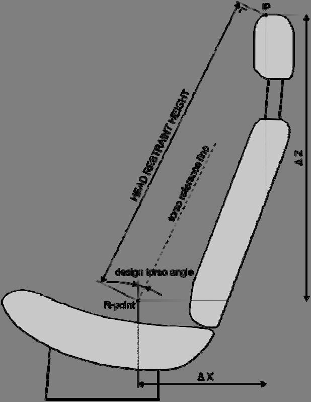
50 50

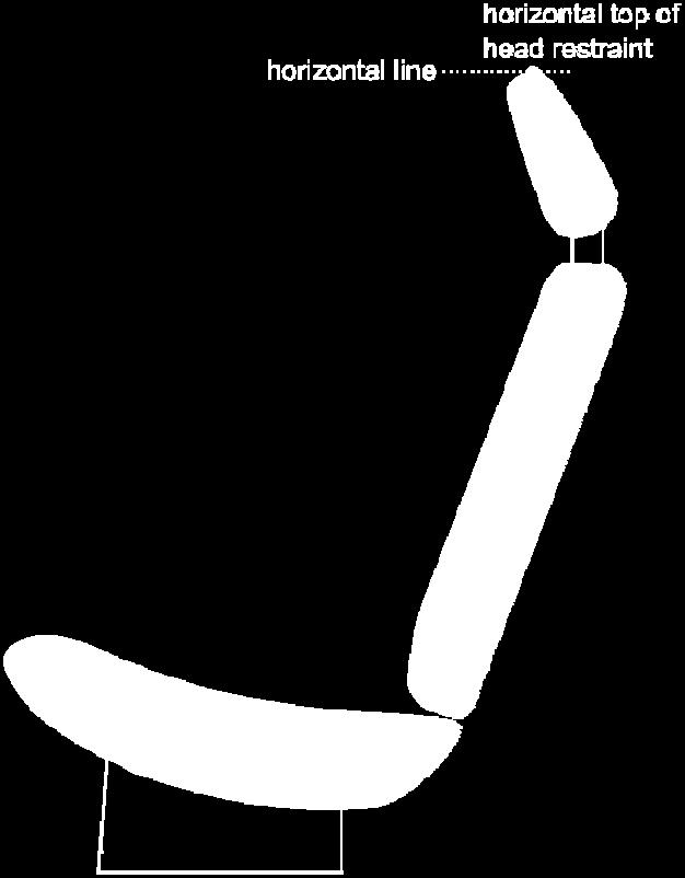
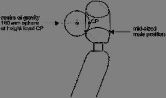
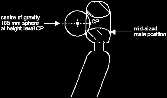
51 Figure 10-4 Figure
52 Annex 11 Backset measurement procedure 1. Purpose Demonstrate compliance with paragraph by measuring the backset using the R-point as the reference point. 2. Procedure for backset measurement using R-point as the reference point Demonstrate compliance with paragraph by measuring the R-point backset of the head restraint [based on the usage of apparatus that facilitates the measurement of coordinates and for its dimensions is based on Figure 1.1 of Annex 1 using the backset measurement apparatus defined in paragraph 2.1. of this Annex and the following procedures: 2.1. Backset measuring apparatus The backset measurement apparatus consists of (see Figure 5-2): A straight edge (lower arm) AB. The lower point A is placed at the R point location. Point B is located at a distance of mm from the R point. The line AB is 2.6 degrees forward of the design torso angle A vertical straight edge (upper arm) BC. Point C is located at a distance of 203 mm vertically up from point B.] 2.2. Adjust the seat such that its H-point coincides with the R-point, in accordance with the following requirements Relationship between the H-point and the R-point When the seat is positioned in accordance to the manufacturer's specifications, following the procedure of Annex 12 the H-point, as defined by its co-ordinates, shall lie within a square of 50 mm side length with horizontal and vertical sides whose diagonals intersect at the R-point, and the actual torso angle is within 5 C of the design torso angle If these conditions are met, the R-point and the design torso angle are used to demonstrate compliance with the provisions of paragraph of this regulation If the H-point or the actual torso angle does not satisfy the requirements of paragraph , the H-point and the actual torso angle are determined twice more (three times in all). If the results of two of these three operations satisfy the requirements, the conditions of paragraph shall apply If the results of at least two of the three operations described in paragraph do not satisfy the requirements of paragraph the centroid of the three measured points or the average of the three measured angles is used and shall be regarded as applicable in all cases where the R-point or the design torso angle is referred to in this Annex Adjust the seat back to its design angle Adjust the front head restraint so that its top point IP is at any height 52
53 between and inclusive of [ ] [750] [720]mm and 800 mm, measured as described in Annex 1. If the lowest position of adjustment is above 800mm, adjust the head restraint to that lowest position of adjustment In the case of head restraint with adjustable backset, adjust the head restraint at the most rearward position, such that the backset is in the maximum position Establish point D on the head restraint, point D being the intersection of a line drawn from point C horizontally in the x-direction, with the front surface of the head restraint, see Figure 1-1 of Annex Measure the distance CD. The backset is the measured distance CD minus 71 mm Measure the X-coordinate of point D. The R-point backset is the difference between the X-coordinate of point D and the X-coordinate of the back-ofhead of the mid-size male as given in Table 1 of Annex
54 Annex Purpose Energy absorption test procedure for head restraint 2. Seat set-up Evaluate the energy absorption ability of the head restraint by demonstrating compliance with paragraph of this Regulation in accordance with this Annex. The seat shall be either mounted in the vehicle or firmly secured to the test bench, as mounted in the vehicle with the attachment parts provided by the manufacturer, so as to remain stationary when the impact is applied. The seat back is adjusted as specified in paragraph of the Regulation. The head restraint shall be mounted on the seat-back as in the vehicle. Where the head restraint is separate, it shall be secured to the part of the vehicle structure to which it is normally attached. 3. Procedure for energy absorption Adjustable head restraints shall be measured in any height and backset position of adjustment Test equipment Use an impactor with a semispherical headform of a mm diameter. The headform and associated base have a combined mass such that at a speed of not more than 24.1 km/h at the time of impact an energy of 152 ± 6 Joule will be reached Instrument the impactor with an acceleration sensing device whose output is recorded in a data channel that conforms to the requirements for a 600 Hz channel class filter as specified in [ISO Standard 6487 (2002)]. The axis of the acceleration-sensing device coincides with the geometric center of the headform and the direction of impact. As an alternative the impactor can be equipped with 2 accelerometers sensing in the direction of impact and placed symmetrically in comparison to the geometric centre of the spherical headform. In this case the deceleration rate shall be taken as the simultaneous average of the readings on the two accelerometers Accuracy of the test equipment Acceleration: Speed: The recording instruments used shall be such that measurements can be made with the following degrees of accuracy: Accuracy = ± 5 per cent of the actual value; Cross-axis sensitivity = < 5 per cent of the lowest point on the scale. Accuracy: ± 2.5 per cent of the actual value; Sensitivity: 0.5 km/h. 54
55 Time recording: The instrumentation shall enable the action to be recorded throughout its duration and readings to be made to within one one-thousandth of a second; The beginning of the impact at the moment of first contact between the headform and the item being tested shall be detected on the recordings used for analyzing the test Test procedure Propel the impactor toward the head restraint. At the time of impact,,the longitudinal axis of the impactor is within ± 2 of being horizontal and parallel to the vehicle longitudinal axis and the impactor speed shall be not more than 24.1 km/h Impact the front surface of the seat or head restraint at any point with a height greater than 635 mm from the R-point and within a lateral distance from the head restraint vertical centreline of 70 mm and measure the acceleration. 55
56 Annex Purpose Height retention test procedure Demonstrate compliance with the height retention requirements of paragraph of this Regulation in accordance with this Annex. 2. Procedures for height retention 2.1. Seat set-up Adjust the adjustable head restraint so that its effective top is at any of the following height positions at any backset position: For front outboard designated seating positions: The highest position; and Not less than, but closest to 800 mm; For rear outboard and front centre designated seating positions: The highest position; and Not less than, but closest to 720 mm For rear centre designated seating positions: The highest position; and Not less than, but closest to 700 mm Orient a cylindrical test device having a mm diameter in plane view (perpendicular to the axis of revolution), and a mm length in profile (through the axis of revolution) such that the axis of the revolution is horizontal and in the longitudinal vertical plane through the vertical longitudinal zero plane of the head restraint. Position the midpoint of the bottom surface of the cylinder in contact with the head restraint Establish initial reference position by applying a vertical downward load of 50 ± 1 N at a rate of 250 ± 50 N/minute. Determine the reference position of the cylinder after 5 seconds at this load. Mark the initial reference position for the head restraint Measure the vertical distance between the lowest point on the underside of the head restraint and the top of the seat back (see paragraph 2.9. of this Annex) Increase the load at the rate of N/minute to at least 500 N and maintain this load for not less than 5 seconds Reduce the load at a rate of 250 ± 50 N/m until the load is completely removed. Maintain this condition for no more than two minutes. Increase the load at a rate of 250 ± 50 N/minute to 50 ± 56
57 1 N and, after 5 seconds and while maintaining this load, determine the position of the cylindrical device with respect to its initial reference position Repeat the measurement of the vertical distance measured between the lowest point on the underside of the head restraint and the top of the seat back. (see paragraph 2.9. of this annex) 2.8. Compare the measurements from paragraphs 2.4. and 2.7. of this Annex. The difference is the measurement required to comply with paragraph of the Regulation If the design of the head restraint is such that it is not possible to measure to the top of the seat then the vertical measurement shall be taken by marking a horizontal line across the front of the seat back at least 25 mm below the lowest point of the head restraint and the measurement shall be taken from this line to the underside of the head restraint. 57
58 Annex 14 Dynamic performance test procedure 1. Purpose Demonstrate compliance with paragraph 5.3. in accordance with this Annex, using a 50th percentile male Hybrid III test dummy: BioRID II UN, test dummy. 2. Test equipment 2.1. An acceleration or deceleration test sled th percentile male test dummy BioRID II UN Conforming to Addendum 1 to the Mutual Resolution M.R.1 (ECE/TRANS/WP.29/1101/Add.1) Equipment for measuring the head to torso angle Equipment for measuring and recording sled accelerations. 3. Procedures for test set-up 3.1. Seat Assembly Independent of the Vehicle (BioRID II UN) An acceleration sled with the dummy seated facing the direction of motion shall be used. Sled accelerations shall be measured by an appropriate accelerometer attached to the sled platform The temperature in the test laboratory shall be 22.5º ± 3ºC with a relative humidity of between 10 per cent and 70 per cent. The test dummy and seat being tested shall be soaked at this temperature for at least 3 hours prior to the test. All tests shall be performed with the active elements of the system designed to operate during rear impact set to their operation condition (e.g. Active head restraint, Seat belt pre-tensioner). The time to fire (TTF) required for a specific elements of the active head restraint shall be specified by the vehicle manufacturer Acceleration Sled The parts of the vehicle structure considered essential for the replication of the vehicle rigidity regarding the seat, its anchorages, the safety-belt anchorages and the head restraints shall be secured to the sled. It shall be so constructed that no permanent deformation appears after the test. Where the upper anchorage has an adjustable height position, it shall be set nearest to the mid-range position permitted by the design The sled shall be capable of accommodating, in an appropriate manner, such equipment as may be specified by the manufacturer as necessary for 58
59 the correct functioning of advanced head restraint systems (active head restraints) A toe board comprising a horizontal section and a forward facing section oriented at 45 º from the horizontal shall be provided Some sled motion is allowed at the initiation of the test (T=0) however, the dummy s head, T1 vertebra, and the sled should have the same velocity ± 0.1m/s at T=0. The back of the dummy s head and T1 vertebra should be in the same position (± 5mm) relative to the head restraint at T=0 as the initial test set-up Mounting the seat on the sled Mount the seat, including all of its adjustment mechanisms and hardware that normally connects it to the vehicle floor on the sled platform so that the seat s orientation relative to the horizontal is the same as it would be in the vehicle. The gap between the front of the seat and rear of the toe board shall be no more than 100 mm. Instrument the platform with an accelerometer mounted such that its sensitive axis is parallel to the direction of test platform travel Seat Adjustment The seat shall be set as specified by the manufacturer, with regard to both the design position of the seat back (see paragraph 3.4 of the gtr) and the position of the seat itself. This position shall be the one where the H-point coincides with R50 point. In the absence of any specification declared by the manufacturer, the procedures of paragraphs to shall apply Where no adjustment is specified, the seat shall be adjusted to its mid-position in both the horizontal and vertical directions. If an adjustment position does not exist midway between those positions, place the seat midway between the most forward and most rearward position. The closest adjustment position to the rear of the midpoint shall be used Where no cushion adjustment is specified, and where the seat cushion is adjustable independently of the seat back, adjust the seat cushion inclination to its mid-position. All other cushion adjustments shall be in a fully retracted position, with the exception of cushion side bolsters which shall be set to their widest position Any adjustable lumbar supports shall be positioned so that the lumbar support is in its lowest retracted or deflated position. Arm rests shall be set in the stowed position Any other seat adjustment device must be set in it most retracted or deflated position Where no design torso angle is specified and where the seat back is adjustable, it shall be set at a torso angle closest to 25º ±1º from the vertical, as measured using the three-dimensional H-point machine, as specified in Annex 3. If there is more than one inclination position close to a torso angle of 25 º then it shall be set to the position closest to and rearward of 25 º Head Restraint Adjustment 59
60 If the head restraint adjusts automatically, the adjustments from to shall apply Adjust the head restraint to the position intended for use by the 50 percentile male, as specified by the manufacturer. [If not available follow.below] Where the adjustment of the head restraint is not automatic, it shall be set in accordance with the manufacturers specification If a locking position midway between the lowest and the highest position does not exist, adjust the head restraint to the position determined by the paragraphs below. If a locking position exists within 10 mm vertically upwards from the geometric mid-position, this shall be the test position. If no locking position exists within 10 mm vertically upwards from the geometric mid-position then the next locking position down shall be the test position. When the head restraint has a locking fore-aft adjustment, it shall be in the midpoint. If a locking position exists within 10 mm horizontally forward from the geometric mid-position, this shall be the test position. If no locking position exists within 10 mm horizontally forwards from the geometric midposition then the next locking position rearwards shall be the test position. If no fore-aft locking positions are available for the head restraint it shall be tilted fully rearward BioRID II UN Reference measurement Using the 3D-H measuring machine, check that the H-point coincides with the R50 point, in accordance with the following requirements. The procedure set out in annex 12 shall be used to verify the H-point relationship to the R50 point specified by the manufacturer. The relative positions of the R point and the H-point relationship shall be considered satisfactory for the seating position in question if the "H"-point, lies within a square of 50 mm side length with horizontal and vertical sides F whose diagonals intersect at the R50 point, and the torso angle is within 5 of the design torso angle Back of the head reference position The back of the head reference position for the BioRID II UN is the value for the back of the head as determined for the 50 percentile in Table 10-1 of Annex 10 of this regulation with reference to the specified torso angle minus 15 mm (increasing the backset as shown in figure x below). Where no design torso angle is specified, set the angle as specified in paragraph Both the measured H-point and angle shall be used when referencing Table 10-1 Annex Dummy Installation The dummy s clothing shall comprise of two pairs of shorts and two shirts made of a nylon fabric. The fabric has a different texture on the outside as it does on the inside shiny and matt. The dummy shall be dressed with both sets of clothing such that the shiny sides of the materials come face to face 60

61 with each other. Shoes are men s dress oxford type, US size 11 (European size 45) extra wide that meet military specifications MIL-S-13192P. Each shoe weighs [ /- 0.2 kg] and has an overall length of mm The seat shall be in an unloaded condition for at least 15 minutes before installing the dummy The appropriate lifting tools and the attachment points recommended by the dummy manufacturer shall be used to position the dummy in the seat. The dummy shall initially be installed with its H-point rearward of the target H-point and the pelvis only moved forward to achieve the position indicated in paragraph below. In the event that the dummy is moved forward of the specified target H-point the dummy shall be removed from the seat and the complete installation procedure repeated. It is not permissible to push the pelvis rearward to bring the pelvis H-point into line with the specified H-point position Adjust the test dummy s midsagittal plane to be vertical and aligned with the centerline of the seat. The instrumentation platform in the head shall be laterally level within ±0, [Adjust the pelvis angle to the actual torso angle recorded by the procedure specified in paragraph xxxx plus 1.5 ± 2.5 / Adjust the pelvis angle to 26.5 ± 2.5.] The BioRID shall be installed such that its H-point is positioned 20 mm ± 10 mm forward of the R 50 -point, as shown in Figure x below, while keeping the pelvis angle within the range specified in paragraph above. Figure [X] [ Back of head adjustment The back of head (the most rearward position of the head when the head is horizontally level +/- 1º) of the BioRID shall be positioned at the reference 61
Economic and Social Council
 United Nations Economic and Social Council ECE/TRANS/WP.29/GRSP/2018/34 Distr.: General 21 September 2018 Original: English Economic Commission for Europe Inland Transport Committee World Forum for Harmonization
E/ECE/324/Rev.1/Add.16/Rev.5 E/ECE/TRANS/505/Rev.1/Add.16/Rev.5
 26 June 2014 Agreement Concerning the Adoption of Uniform Technical Prescriptions for Wheeled Vehicles, Equipment and Parts which can be Fitted and/or be Used on Wheeled Vehicles and the Conditions for
Comparison of ECE R17-08 (including amendment adopted at the 146th WP29(Nov., 08) and ECE R17-09(GRSP/2009/7 with correction proposed by GRSP-45-06).
 and ECE R17-09(GRSP/2009/7 with correction proposed by GRSP-45-06).") Comparison of ECE R17-08 (including amendment adopted at the 146th WP29(Nov., 08) and ECE R17-09( with correction proposed by GRSP-45-06). Legend Proposals by EC are in bold and black. Proposals by Japan
Comparison of ECE R17-08 (including amendment adopted at the 146th WP29(Nov., 08) and ECE R17-09( with correction proposed by GRSP-45-06). Legend Proposals by EC are in bold and black. Proposals by Japan
Proposal for 10 series of amendments to Regulation No. 17 (Strength of seat)
") Submitted by the expert from CLEPA Informal document GRSP-64-25 (64 th GRSP, 11-14 December 2018, agenda item 9) Proposal for 10 series of amendments to Regulation No. 17 (Strength of seat) The text reproduced
Submitted by the expert from CLEPA Informal document GRSP-64-25 (64 th GRSP, 11-14 December 2018, agenda item 9) Proposal for 10 series of amendments to Regulation No. 17 (Strength of seat) The text reproduced
GTR Rev.1. Note:
 GTR7-06-10. Rev.1 Note: GTR 7 Head Restraints, specifies the use of the Hybrid III dummy for the purposes of assessing protection against whiplash associated disorder resulting from a rear impact. However,
Informal Document N 20 (30th GRSP, 3-6 December 2001, agenda item 1.4) Insert in the "CONTENTS" the headlines of new annexes 10 & 11 to read:
 Insert in the CONTENTS the headlines of new annexes 10 & 11 to read:") 30 November 2001 Informal Document N 20 (30th GRSP, 3-6 December 2001, agenda item 1.4) Draft Amendments To Regulation No. 17: (Strength of Seats) page ii Insert in the "CONTENTS" the headlines of new
30 November 2001 Informal Document N 20 (30th GRSP, 3-6 December 2001, agenda item 1.4) Draft Amendments To Regulation No. 17: (Strength of Seats) page ii Insert in the "CONTENTS" the headlines of new
(Acts whose publication is not obligatory) COUNCIL COUNCIL DIRECTIVE
 COUNCIL COUNCIL DIRECTIVE") 12. 8. 74 Official Journal of the European Communities No L 221/ 1 II (Acts whose publication is not obligatory) COUNCIL COUNCIL DIRECTIVE of 22 July 1974 on the approximation of the laws of the Member
12. 8. 74 Official Journal of the European Communities No L 221/ 1 II (Acts whose publication is not obligatory) COUNCIL COUNCIL DIRECTIVE of 22 July 1974 on the approximation of the laws of the Member
Economic and Social Council
 United Nations Economic and Social Council ECE/TRANS/WP.29/2017/59 Distr.: General 5 April 2017 Original: English Economic Commission for Europe Inland Transport Committee World Forum for Harmonization
E/ECE/324/Rev.1/Add.79/Rev.1 E/ECE/TRANS/505/Rev.1/Add.79/Rev.1
 25 October 2011 Agreement Concerning the adoption of uniform technical prescriptions for wheeled vehicles, equipment and parts which can be fitted and/or be used on wheeled vehicles and the conditions
ECE/TRANS/WP.29/GRSP/2014/10
 Submitted by the expert from France Proposal for amendment of document ECE/TRANS/WP.29/GRSP/2014/10 Informal document GRSP-55-20-Rev1 (55th GRSP, 19-23 May 2014, agenda item 21) Formatted: French (France)
E/ECE/324/Rev.1/Add.57/Rev.3 E/ECE/TRANS/505/Rev.1/Add.57/Rev.3
 30 November 2017 Agreement Concerning the Adoption of Harmonized Technical United Nations Regulations for Wheeled Vehicles, Equipment and Parts which can be Fitted and/or be Used on Wheeled Vehicles and
E/ECE/324 Rev.1/Add.20/Rev.2/Amend.2 E/ECE/TRANS/505 AGREEMENT
 25 March 2003 AGREEMENT CONCERNING THE ADOPTION OF UNIFORM TECHNICAL PRESCRIPTIONS FOR WHEELED VEHICLES, EQUIPMENT AND PARTS WHICH CAN BE FITTED AND/OR BE USED ON WHEELED VEHICLES AND THE CONDITIONS FOR
DRAFT: Front Contact Surface Head Restraint
 DRAFT: Front Contact Surface Head Restraint 20071012 PROPOSAL FOR DRAFT AMENDMENTS TO DRAFT GTR ON HEAD RESTRAINTS Transmitted by the expert from the Netherlands Note: The text reproduced below was prepared
Collective amendments to UN Regulations Nos. 16, 44, 94, 129 and 137
 Submitted by the expert from EC Informal document GRSP-63-01 (63rd GRSP, 14-18 May 2018 agenda item 22) Collective amendments to UN Regulations Nos. 16, 44, 94, 129 and 137 Submitted by the expert from
Proposal for the 02 series of amendments to Phase 2 of Regulation No. 129 (Enhanced Child Restraint Systems)
") Submitted by the expert from France Informal document GRSP-58-08 (58th GRSP, 7-11 December 2015, agenda item 19) Proposal for the 02 series of amendments to Phase 2 of Regulation No. 129 (Enhanced Child
Submitted by the expert from France Informal document GRSP-58-08 (58th GRSP, 7-11 December 2015, agenda item 19) Proposal for the 02 series of amendments to Phase 2 of Regulation No. 129 (Enhanced Child
Proposal. Submitted. agenda item 17) supersedes made 2017/04/19) Insert new. of the. The minimum size area." Insert new. inform the.
 supersedes made 2017/04/19) Insert new. of the. The minimum size area. Insert new. inform the.") Submitted by the expert from France Informal document GRSP-61-15-Rev.11 (61 st GRSP, 08-12 May 2017 agenda item 17) Proposal for Supplement 3 to the 01 series of amendments to Regulation No. 129 Submitted
Submitted by the expert from France Informal document GRSP-61-15-Rev.11 (61 st GRSP, 08-12 May 2017 agenda item 17) Proposal for Supplement 3 to the 01 series of amendments to Regulation No. 129 Submitted
E/ECE/324/Rev.2/Add.141 E/ECE/TRANS/505/Rev.2/Add.141
 30 January 2017 Agreement Concerning the Adoption of Uniform Technical Prescriptions for Wheeled Vehicles, Equipment and Parts which can be Fitted and/or be Used on Wheeled Vehicles and the Conditions
Draft for comments only Not to be cited as East African Standard
 EAST AFRICAN STANDARD CD/K/011:2008 ICS 43.040.60 Uniform provisions concerning the approval of vehicles with regard to safety-belt anchorages EAST AFRICAN COMMUNITY EAC 2010 First Edition 2010 Foreword
E/ECE/324/Rev.2/Add.128/Rev.2/Amend.2 E/ECE/TRANS/505/Rev.2/Add.128/Rev.2/Amend.2
 10 August 2018 Agreement Concerning the Adoption of Harmonized Technical United Nations Regulations for Wheeled Vehicles, Equipment and Parts which can be Fitted and/or be Used on Wheeled Vehicles and
Economic and Social Council
 United Nations Economic and Social Council ECE/TRANS/WP.29/GRSP/2018/29 Distr.: General 26 September 2018 Original: English Economic Commission for Europe Inland Transport Committee World Forum for Harmonization
AGREEMENT CONCERNING THE ADOPTION OF UNIFORM CONDITIONS OF APPROVAL AND RECIPROCAL RECOGNITION OF APPROVAL FOR MOTOR VEHICLE EQUIPMENT AND PARTS
 E/ECE/324 Rev.1/Add.24/Rev.1* 26 April 1990 AGREEMENT CONCERNING THE ADOPTION OF UNIFORM CONDITIONS OF APPROVAL AND RECIPROCAL RECOGNITION OF APPROVAL FOR MOTOR VEHICLE EQUIPMENT AND PARTS done at Geneva
E/ECE/324/Rev.1/Add.33/Rev.3 E/ECE/TRANS/505/Rev.1/Add.33/Rev.3
 12 November 2015 Agreement Concerning the Adoption of Uniform Technical Prescriptions for Wheeled Vehicles, Equipment and Parts which can be Fitted and/or be Used on Wheeled Vehicles and the Conditions
E/ECE/324/Add.10/Rev.3 E/ECE/TRANS/505/Add.10/Rev.3
 12 November 2015 Agreement Concerning the Adoption of Uniform Technical Prescriptions for Wheeled Vehicles, Equipment and Parts which can be fitted and/or be used on Wheeled Vehicles and the Conditions
Amendment of UN ECE R100 regarding in-use requirements for vehicles of category L Status:
 0 1. Scope The following prescription apply to safety requirements with respect to the electric power train of road vehicles of categories M and N, with a maximum design speed exceeding 25 km/h and vehicles
Head Restraints. TECHNICAL STANDARDS DOCUMENT No. 202, Revision 1R. (Ce document est aussi disponible en français)
") TECHNICAL STANDARDS DOCUMENT No. 202, Revision 1R Head Restraints The text of this document is based on Federal Motor Vehicle Safety Standard No. 202a, Head Restraints, as published in the United States
TECHNICAL STANDARDS DOCUMENT No. 202, Revision 1R Head Restraints The text of this document is based on Federal Motor Vehicle Safety Standard No. 202a, Head Restraints, as published in the United States
E/ECE/324/Rev.1/Add.57/Rev.2/Amend.4 E/ECE/TRANS/505/Rev.1/Add.57/Rev.2/Amend.4
 11 July 2016 Agreement Concerning the Adoption of Uniform Technical Prescriptions for Wheeled Vehicles, Equipment and Parts which can be Fitted and/or be Used on Wheeled Vehicles and the Conditions for
Requirements on vehicle occupant protection, including interior fittings, head restraints, seat belts, vehicle doors
 L 42/70 EN Official Journal of the European Union 17.2.2015 ANNEX XIII Requirements on vehicle occupant protection, including interior fittings, head restraints, seat belts, vehicle doors 1. Definitions
Economic and Social Council
 United Nations Economic and Social Council ECE/TRANS/WP.29/GRSP/2018/9 Distr.: General 28 February 2018 Original: English Economic Commission for Europe Inland Transport Committee World Forum for Harmonization
Having regard to the Treaty establishing the European Economic Community,
 No L 341 / 20 Official Journal of the European Communities 6. 12. 90 COMMISSION DIRECTIVE of 30 October 1990 adapting to technical progress Council Directive 77/ 649/ EEC on the approximation of the laws
Informal document No. 80th GRSG, 2-6 April 2001, agenda item 6. Distr. GENERAL
 Informal document No. 80th GRSG, 2-6 April 2001, agenda item 6. Distr. GENERAL 12 TRANS/WP29/GRSG/1999/12/Rev.2 13 February 2001 Original: ENGLISH ECONOMIC COMMISSION FOR EUROPE INLAND TRANSPORT COMMITTEE
E/ECE/324/Rev.2/Add.102/Rev.1 E/ECE/TRANS/505/Rev.2/Add.102/Rev.1
 30 August 2011 Agreement Concerning the adoption of uniform technical prescriptions for wheeled vehicles, equipment and parts which can be fitted and/or be used on wheeled vehicles and the conditions for
AGREEMENT CONCERNING THE ADOPTION OF UNIFORM CONDITIONS OF APPROVAL AND RECIPROCAL RECOGNITION OF APPROVAL FOR MOTOR VEHICLE EQUIPMENT AND PARTS
 E/ECE/TRANS/505A 28 April 1972 AGREEMENT CONCERNING THE ADOPTION OF UNIFORM CONDITIONS OF APPROVAL AND RECIPROCAL RECOGNITION OF APPROVAL FOR MOTOR VEHICLE EQUIPMENT AND PARTS done at Geneva on 20 March
ETRTO/OICA proposal for a new Regulation on the installation of tyres
 Submitted by the experts from ETRTO and OICA Informal document GRRF-75-20 (75 th GRRF, 17-19 September 2013 agenda item 10(a)) ETRTO/OICA proposal for a new Regulation on the installation of tyres The
E/ECE/324 AGREEMENT. Addendum 47: Regulation No. 48. Revision 4 - Amendment 1
 } Rev.1/Add.47/Rev.4/Amend.1 10 November 2006 AGREEMENT CONCERNING THE ADOPTION OF UNIFORM TECHNICAL PRESCRIPTIONS FOR WHEELED VEHICLES, EQUIPMENT AND PARTS WHICH CAN BE FITTED AND/OR BE USED ON WHEELED
E/ECE/324/Rev.2/Add.128/Rev.1/Amend.2 E/ECE/TRANS/505/Rev.2/Add.128/Rev.1/Amend.2
 E/ECE/324/Rev.2/Add.128/Rev.1/Amend.2 26 July 2017 Agreement Concerning the Adoption of Uniform Technical Prescriptions for Wheeled Vehicles, Equipment and Parts which can be Fitted and/or be Used on Wheeled
AUTOMOTIVE INDUSTRY STANDARD PRINTED BY THE AUTOMOTIVE RESEARCH ASSOCIATION OF INDIA P.B. NO. 832, PUNE
 AUTOMOTIVE INDUSTRY STANDARD Automotive Vehicles - Seats, their Anchorages and Head Restraints for Passenger Vehicles of Categories M2, M3 and Goods Vehicles of Category N - Specifications PRINTED BY THE
E/ECE/324/Rev.2/Add.136 E/ECE/TRANS/505/Rev.2/Add.136
 22 June 2016 Agreement Concerning the Adoption of Uniform Technical Prescriptions for Wheeled Vehicles, Equipment and Parts which can be Fitted and/or be Used on Wheeled Vehicles and the Conditions for
Economic and Social Council
 United Nations Economic and Social Council Distr.: General 1 February 2013 Original: English Economic Commission for Europe Inland Transport Committee World Forum for Harmonization of Vehicle Regulations
E/ECE/324/Rev.1/Add.38/Rev.2 E/ECE/TRANS/505/Rev.1/Add.38/Rev.2
 E/ECE/324/Rev.1/Add.38/Rev.2 24 January 2018 Agreement Concerning the Adoption of Harmonized Technical United Nations Regulations for Wheeled Vehicles, Equipment and Parts which can be Fitted and/or be
E/ECE/324/Rev.1/Add.93/Rev.3 E/ECE/TRANS/505/Rev.1/Add.93/Rev.3
 14 September 2017 Agreement Concerning the Adoption of Uniform Technical Prescriptions for Wheeled Vehicles, Equipment and Parts which can be Fitted and/or be Used on Wheeled Vehicles and the Conditions
Occupant Restraint Systems in Frontal Impact
 TEST METHOD 208 Occupant Restraint Systems in Frontal Impact Revised: Issued: December 1996R January 20, 1976 (Ce document est aussi disponible en français) Table of Contents 1. Introduction... 1 2. General
E/ECE/324/Rev.2/Add.104/Rev.2 E/ECE/TRANS/505/Rev.2/Add.104/Rev.2
 28 September 2011 Agreement Concerning the adoption of uniform technical prescriptions for wheeled vehicles, equipment and parts which can be fitted and/or be used on wheeled vehicles and the conditions
E/ECE/324/Rev.1/Add.15/Rev.9 E/ECE/TRANS/505/Rev.1/Add.15/Rev.9
 4 June 2018 Agreement Concerning the Adoption of Harmonized Technical United Nations Regulations for Wheeled Vehicles, Equipment and Parts which can be Fitted and/or be Used on Wheeled Vehicles and the
Introduction of Booster Cushions in R129
 Informal document GRSP-64-16 (64th GRSP, 11-14 December 2018 agenda item 19) Introduction of Booster Cushions in R129 Clepa Proposal for R129/04 Series of Amendments GRSP 64th Session Farid Bendjellal
E/ECE/324/Rev.1/Add.15/Rev.8/Amend.4 E/ECE/TRANS/505/Rev.1/Add.15/Rev.8/Amend.4
 26 July 2017 Agreement Concerning the Adoption of Uniform Technical Prescriptions for Wheeled Vehicles, Equipment and Parts which can be Fitted and/or be Used on Wheeled Vehicles and the Conditions for
AGREEMENT. (Revision 2, including the amendments entered into force on 16 October 1995) Addendum 25: Regulation No. 26.
 Addendum 25: Regulation No. 26.") 21 March 1997 AGREEMENT CONCERNING THE ADOPTION OF UNIFORM TECHNICAL PRESCRIPTIONS FOR WHEELED VEHICLES, EQUIPMENT AND PARTS WHICH CAN BE FITTED AND/OR BE USED ON WHEELED VEHICLES AND THE CONDITIONS FOR
21 March 1997 AGREEMENT CONCERNING THE ADOPTION OF UNIFORM TECHNICAL PRESCRIPTIONS FOR WHEELED VEHICLES, EQUIPMENT AND PARTS WHICH CAN BE FITTED AND/OR BE USED ON WHEELED VEHICLES AND THE CONDITIONS FOR
Economic and Social Council
 United Nations Economic and Social Council ECE/TRANS/WP.29/2018/39 Distr.: General 9 April 2018 Original: English Economic Commission for Europe Inland Transport Committee World Forum for Harmonization
UNIFORM PROVISIONS CONCERNING THE APPROVAL OF VEHICLES WITH REGARD TO THE BEHAVIOUR OF THE STRUCTURE OF THE IMPACTED VEHICLE IN A REAR-END COLLISION
 246 United Nations Treaty Series Nations Unies Recueil des Trait s 1975 No. 4789. AGREEMENT CONCERNING THE ADOPTION OF UNIFORM CONDITIONS OF APPROVAL AND RECIPROCAL RECOGNITION OF APPROVAL FOR MOTOR VE
Comments to ECE/TRANS/WP.29/GRE/2011/29
 Transmitted by the expert from OICA Informal document No. GRE-65-23-Rev.1 (65th GRE, 28-31 March 2011, agenda item 5(f)) Comments to The text reproduced below was prepared by the expert from OICA to propose
E/ECE/324/Rev.1/Add.43/Rev.3/Amend.7 E/ECE/TRANS/505/Rev.1/Add.43/Rev.3/Amend.7
 16 January 2019 Agreement Concerning the Adoption of Harmonized Technical United Nations Regulations for Wheeled Vehicles, Equipment and Parts which can be Fitted and/or be Used on Wheeled Vehicles and
} Rev.1/Add.52/Rev.2/Amend.2
 19 February 2010 AGREEMENT CONCERNING THE ADOPTION OF UNIFORM TECHNICAL PRESCRIPTIONS FOR WHEELED VEHICLES, EQUIPMENT AND PARTS WHICH CAN BE FITTED AND/OR BE USED ON WHEELED VEHICLES AND THE CONDITIONS
E/ECE/324/Rev.1/Add.90/Rev.3 E/ECE/TRANS/505/Rev.1/Add.90/Rev.3
 2 December 2013 Agreement Concerning the Adoption of Uniform Technical Prescriptions for Wheeled Vehicles, Equipment and Parts which can be Fitted and/or be Used on Wheeled Vehicles and the Conditions
Economic and Social Council
 United Nations Economic and Social Council ECE/TRANS/WP.29/GRSP/2017/27 Distr.: General 22 September 2017 Original: English Economic Commission for Europe Inland Transport Committee World Forum for Harmonization
Date of hosting on website: 26 th October 2017 Last date for comments: 25 th November 2017
 Date of hosting on website: 26 th October 2017 Last date for comments: 25 th November 2017 CHECK LIST FOR PREPARING AUTOMOTIVE INDUSTRY STANDARD Draft AIS-146/D0 : Requirements applying to stands fitted
Revision 1. Incorporating all valid text up to: Supplement 5 to the original version of the Regulation Date of entry into force: 7 December 2002
 L 120/40 Official Journal of the European Union 13.5.2010 Only the original UN/ECE texts have legal effect under international public law. The status and date of entry into force of this Regulation should
Common position by FR and CEMA on mechanical couplings for towed vehicles 28/9/2015
 Common position by FR and CEMA on mechanical couplings for towed vehicles 28/9/2015 ANNEX XXXIV Requirements on mechanical couplings 1. Definitions For the purposes of this Annex: 1.1. Mechanical coupling
(62 nd GRSP, December 201 agenda item 26(g)) Regulation No. 80. ms comparison of static und mic test procedure.
) Regulation No. 80. ms comparison of static und mic test procedure.") Regulation No. 80 Submitted by the expert from Germany Informal document GRSP-62-36 (62 nd GRSP, 12-15 December 201 agenda item 26(g)) ms comparison of static und mic test procedure mäus Zak erlach d traffic
Regulation No. 80 Submitted by the expert from Germany Informal document GRSP-62-36 (62 nd GRSP, 12-15 December 201 agenda item 26(g)) ms comparison of static und mic test procedure mäus Zak erlach d traffic
Draft for comments only Not to be cited as East African Standard
 EAST AFRICAN STANDARD CD/K/021:2008 ICS 43.040.50 Motor vehicle safety Steering mechanism of motor vehicles (Category M 1 only) Behaviour on impact EAST AFRICAN COMMUNITY EAC 2010 First Edition 2010 CD/K/021:2008
1. Page 29/29, Add following new Annexure II and renumber existing Annexure II and its reference in introduction as Annexure III.
 Amendment No. 4 (August 11, 2017) To AIS 023 / 2005 Automotive Vehicles - Seats, their Anchorages and Head Restraints for Passenger Vehicles of Categories L7, M2, M3 and Goods Vehicles of Category N Specifications
E/ECE/324/Rev.1/Add.54/Rev.2/Amend.1 E/ECE/TRANS/505/Rev.1/Add.54/Rev.2/Amend.1
 28 October 2016 Agreement Concerning the Adoption of Uniform Technical Prescriptions for Wheeled Vehicles, Equipment and Parts which can be Fitted and/or be Used on Wheeled Vehicles and the Conditions
Draft amendments for ECE/TRANS/WP.29/GRSG/2015/27
 Submitted by the expert from Japan Informal document GRSG-109-08 (109 th GRSG, 29 September-2 October 2015, agenda item 11) Draft amendments for ECE/TRANS/WP.29/GRSG/2015/27 The text reproduced below was
AGREEMENT CONCERNING THE ADOPTION OF UNIFORM CONDITIONS OF APPROVAL AND RECIPROCAL RECOGNITION OF APPROVAL FOR MOTOR VEHICLE EQUIPMENT AND PARTS
 E/ECE/324 Rev.1/Add.72 29 February 1988 AGREEMENT CONCERNING THE ADOPTION OF UNIFORM CONDITIONS OF APPROVAL AND RECIPROCAL RECOGNITION OF APPROVAL FOR MOTOR VEHICLE EQUIPMENT AND PARTS done at Geneva on
(Revision 2, including the amendments which entered into force on 16 October 1995) 01 series of amendments Date of entry into force: 9 February 2017
 01 series of amendments Date of entry into force: 9 February 2017") 22 February 2017 Agreement Concerning the Adoption of Uniform Technical Prescriptions for Wheeled Vehicles, Equipment and Parts which can be Fitted and/or be Used on Wheeled Vehicles and the Conditions
22 February 2017 Agreement Concerning the Adoption of Uniform Technical Prescriptions for Wheeled Vehicles, Equipment and Parts which can be Fitted and/or be Used on Wheeled Vehicles and the Conditions
AGREEMENT. (Revision 2, including the amendments entered into force on 16 October 1995) Addendum 102: Regulation No. 103
 Addendum 102: Regulation No. 103") 21 March 1997 AGREEMENT CONCERNING THE ADOPTION OF UNIFORM TECHNICAL PRESCRIPTIONS FOR WHEELED VEHICLES, EQUIPMENT AND PARTS WHICH CAN BE FITTED AND/OR BE USED ON WHEELED VEHICLES AND THE CONDITIONS FOR
21 March 1997 AGREEMENT CONCERNING THE ADOPTION OF UNIFORM TECHNICAL PRESCRIPTIONS FOR WHEELED VEHICLES, EQUIPMENT AND PARTS WHICH CAN BE FITTED AND/OR BE USED ON WHEELED VEHICLES AND THE CONDITIONS FOR
Proposal for the 07 series of amendments to Regulation No. 16 (Safety-belts)
") Submitted by the experts from France, Japan, Republic of Korea and European Commission Informal document GRSP-59-06-Rev.2 (59th GRSP, 9-13 May 2016, Agenda item 9) Proposal for the 07 series of amendments
Submitted by the experts from France, Japan, Republic of Korea and European Commission Informal document GRSP-59-06-Rev.2 (59th GRSP, 9-13 May 2016, Agenda item 9) Proposal for the 07 series of amendments
ECE/TRANS/180/Add.1/Amend.1
 29 August 2012 Global Registry Created on 18 November 2004, pursuant to Article 6 of the Agreement concerning the establishing of global technical regulations for wheeled vehicles, equipment and parts
Economic and Social Council
 United Nations Economic and Social Council ECE/TRANS/WP.29/2016/83 Distr.: General 31 August 2016 Original: English Economic Commission for Europe Inland Transport Committee World Forum for Harmonization
EXTRACT of chapter XXXIV coupling devices (version of ) ANNEX XXXIV Requirements on mechanical couplings
 ANNEX XXXIV Requirements on mechanical couplings") EXTRACT of chapter XXXIV coupling devices (version of 18.09.2013) ANNEX XXXIV Requirements on mechanical couplings Definitions specific to this Annex Mechanical coupling between tractor and towed vehicle
EXTRACT of chapter XXXIV coupling devices (version of 18.09.2013) ANNEX XXXIV Requirements on mechanical couplings Definitions specific to this Annex Mechanical coupling between tractor and towed vehicle
AGREEMENT. Addendum 113: Regulation No Date of entry into force: 1 February 2003
 2 July 2003 AGREEMENT CONCERNING THE ADOPTION OF UNIFORM TECHNICAL PRESCRIPTIONS FOR WHEELED VEHICLES, EQUIPMENT AND PARTS WHICH CAN BE FITTED AND/OR BE USED ON WHEELED VEHICLES AND THE CONDITIONS FOR
Doc:TED 11(794)W 1 September 2012 Draft Standard Automotive Vehicles - Windscreen Wiping System for 3 Wheeler Vehicles - Specification
W 1 September 2012 Draft Standard Automotive Vehicles - Windscreen Wiping System for 3 Wheeler Vehicles - Specification") For Comments only Doc:TED 11(794)W 1 September 2012 Draft Standard Automotive Vehicles - Windscreen Wiping System for 3 Wheeler Vehicles - Specification Not to be reproduced without permission Last date
For Comments only Doc:TED 11(794)W 1 September 2012 Draft Standard Automotive Vehicles - Windscreen Wiping System for 3 Wheeler Vehicles - Specification Not to be reproduced without permission Last date
Draft new Regulation on uniform provisions concerning the approval of enhanced Child Restraint Systems used onboard of motor vehicles
 Transmitted by the Chair of GRSP Informal document GRSP-50-22-Rev.1 (50th GRSP, 6 9 December 2011, agenda item 18) Draft new Regulation on uniform provisions concerning the approval of enhanced Child Restraint
Proposal for the 02 series of amendments to Phase 2 of Regulation No. 129 (Enhanced Child Restraint Systems)
") Transmitted by the experts from France Informal document GRSP-59-08-Rev.1 (59th GRSP, 9-13 May 2016, agenda item 19) Proposal for the 02 series of amendments to Phase 2 of Regulation No. 129 (Enhanced
Transmitted by the experts from France Informal document GRSP-59-08-Rev.1 (59th GRSP, 9-13 May 2016, agenda item 19) Proposal for the 02 series of amendments to Phase 2 of Regulation No. 129 (Enhanced
Proposal for a new Regulation on Child Restraints Systems Phase 2
 Transmitted by the expert from France Informal document GRSP-53-21 (53rd GRSP, 13-17 May 2013, agenda item 19) Proposal for a new Regulation on Child Restraints Systems Phase 2 Draft working document of
E/ECE/324/Rev.1/Add.91/Rev.1/Amend.2 E/ECE/TRANS/505/Rev.1/Add.91/Rev.1/Amend.2
 7 December 2017 Agreement Concerning the Adoption of Harmonized Technical United Nations Regulations for Wheeled Vehicles, Equipment and Parts which can be Fitted and/or be Used on Wheeled Vehicles and
E/ECE/324/Rev.2/Add.106/Rev.6 E/ECE/TRANS/505/Rev.2/Add.106/Rev.6
 20 June 2014 Agreement Concerning the Adoption of Uniform Technical Prescriptions for Wheeled Vehicles, Equipment and Parts which can be Fitted and/or be Used on Wheeled vehicles and the Conditions for
Proposal for amendments to Regulations Nos. 19, 48 and 98.
 Submitted by the expert from Germany Informal document. GRE-68-15 (68th GRE, 26 29 March 2012, agenda item 5(i)) Proposal for amendments to Regulations Nos. 19, 48 and 98. Submitted by the expert from
E/ECE/324/Rev.2/Add.128/Rev.1 E/ECE/TRANS/505/Rev.2/Add.128/Rev.1
 18 May 2018 Agreement Concerning the Adoption of Harmonized Technical United Nations Regulations for Wheeled Vehicles, Equipment and Parts which can be Fitted and/or be Used on Wheeled Vehicles and the
HEAVY VEHICLES TEST AND ASSESSMENT PROTOCOL
 HEAVY VEHICLES TEST AND ASSESSMENT PROTOCOL Version 1.2 Euro NCAP OCTOBER 2012 EUROPEAN NEW CAR ASSESSMENT PROGRAMME Copyright 2012 Euro NCAP - This work is the intellectual property of Euro NCAP. Permission
in-use requirements for vehicles of category L (Part 1) IMMA contribution to 10/RESS
 IMMA contribution to 10/RESS") 1. Scope IMMA comments 1 The following prescription apply to safety requirements with respect to the electric power train of road vehicles of categories M and N, with a maximum design speed exceeding 25
1. Scope IMMA comments 1 The following prescription apply to safety requirements with respect to the electric power train of road vehicles of categories M and N, with a maximum design speed exceeding 25
The following pages contain the proposals that were made by the participants of the ECE- R21 ad-hoc working group during:
 DRAFT SHORT TERM MODIFICATIONS OF ECE- R21 INTERIOR FITTINGS - Informal document No.1 28 th session of GRSP Agenda item 2.4 INTRODUCTION The following pages contain the proposals that were made by the
E/ECE/324/Rev.1/Add.42/Rev.4 E/ECE/TRANS/505/Rev.1/Add.42/Rev.4
 3 April 2017 Agreement Concerning the adoption of uniform technical prescriptions for wheeled vehicles, equipment and parts which can be fitted and/or be used on wheeled vehicles and the conditions for
Doc:TED 11(794)W Dec Draft Standard Automotive Vehicles - Windscreen Wiping System for 3 Wheeler Vehicles - Specification
W Dec Draft Standard Automotive Vehicles - Windscreen Wiping System for 3 Wheeler Vehicles - Specification") For Comments only Doc:TED 11(794)W Dec 2010 Draft Standard Automotive Vehicles - Windscreen Wiping System for 3 Wheeler Vehicles - Specification Not to be reproduced without permission Last date for receipt
For Comments only Doc:TED 11(794)W Dec 2010 Draft Standard Automotive Vehicles - Windscreen Wiping System for 3 Wheeler Vehicles - Specification Not to be reproduced without permission Last date for receipt
Amendment of UN ECE R100 regarding in-use requirements for vehicles of category L Status: RESS-9-6 Rev.02
 0 1. Scope IMMA comments The following prescription apply to safety requirements with respect to the electric power train of road vehicles of categories M and N, with a maximum design speed exceeding 25
Economic and Social Council
 United Nations Economic and Social Council ECE/TRANS/WP.29/2018/104/Rev.1 Distr.: General 1 October 2018 Original: English Economic Commission for Europe Inland Transport Committee World Forum for Harmonization
E/ECE/324/Rev.1/Add.78/Rev.2/Amend.3 E/ECE/TRANS/505/Rev.1/Add.78/Rev.2/Amend.3
 7 December 2017 Agreement Concerning the Adoption of Harmonized Technical United Nations Regulations for Wheeled Vehicles, Equipment and Parts which can be Fitted and/or be Used on Wheeled Vehicles and
AMENDMENT NO December 2015 AIS-072
 AMENDMENT NO. 2 15 December 2015 To Approval of Restraining Devices for Child Occupants of Power-Driven Vehicles ( Child Restraint System ) 1. Page 9/120, clause 4.5 Substitute following text and figure
E/ECE/324/Rev.2/Add.99/Rev.2-E/ECE/TRANS/505/Rev.2/Add.99/Rev.2
 - 12 August 2013 Agreement Concerning the Adoption of Uniform Technical Prescriptions for Wheeled Vehicles, Equipment and Parts which can be Fitted and/or be Used on Wheeled Vehicles and the Conditions
Economic and Social Council
 United Nations Economic and Social Council ECE/TRANS/WP.29/2017/69 Distr.: General 6 April 2017 Original: English Economic Commission for Europe Inland Transport Committee World Forum for Harmonization
ECE Regulation N th session of GRSP December 2013
 Informal document GRSP-54-35 (54 th GRSP, 17-20 December 2013, agenda item 19) ECE Regulation N 129 54th session of GRSP 17-20 December 2013 17/12/2013 54th Session GRSP 17-20 December 2013 1 From Phase
E/ECE/324/Rev.1/Add.43/Rev.3-E/ECE/TRANS/505/Rev.1/Add.43/Rev.3
 - 27 February 2014 Agreement Concerning the Adoption of Uniform Technical Prescriptions for Wheeled Vehicles, Equipment and Parts which can be Fitted and/or be Used on Wheeled Vehicles and the Conditions
Comments to ECE/TRANS/WP.29/GRE/2011/29
 Transmitted by the expert from OICA Informal Document No. GRE-65-23 (65th GRE, 28-31 March 2011, agenda item 5(f)) Comments to The text reproduced below was prepared by the expert from OICA to propose
E/ECE/324/Rev.1/Add.54/Rev.2/Amend.3 E/ECE/TRANS/505/Rev.1/Add.54/Rev.2/Amend.3
 26 April 2018 Agreement Concerning the Adoption of Harmonized Technical United Nations Regulations for Wheeled Vehicles, Equipment and Parts which can be Fitted and/or be Used on Wheeled Vehicles and the
Proposal for a new 07 series of amendments to Regulation No. 48 (Installation of lighting and light-signalling devices)
") Submitted by the expert from The Netherlands and Italy Informal document GRE-79-29 (79 th GRE, 24-27 April 2018, agenda item 6 (b)) Proposal for a new 07 series of amendments to Regulation No. 48 (Installation
Submitted by the expert from The Netherlands and Italy Informal document GRE-79-29 (79 th GRE, 24-27 April 2018, agenda item 6 (b)) Proposal for a new 07 series of amendments to Regulation No. 48 (Installation
(Amendments to ECE/TRANS/WP.29/GRSG/2018/24)
") Submitted by the Chair of the IWG on VRU-Proxi Informal document GRSG-115-10 (115th GRSG, 9-12 October 2018 Agenda item 6(b)) Revised proposal for a new UN Regulation on uniform provisions concerning the
Submitted by the Chair of the IWG on VRU-Proxi Informal document GRSG-115-10 (115th GRSG, 9-12 October 2018 Agenda item 6(b)) Revised proposal for a new UN Regulation on uniform provisions concerning the
Economic and Social Council
 United Nations Economic and Social Council Distr.: General 25 July 2016 Original: English Economic Commission for Europe Inland Transport Committee World Forum for Harmonization of Vehicle Regulations
E/ECE/324/Rev.1/Add.94/Rev.1 E/ECE/TRANS/505/Rev.1/Add.94/Rev.1
 16 November 2011 Agreement Concerning the Adoption of Uniform Technical Prescriptions for Wheeled Vehicles, Equipment and Parts which can be Fitted and/or be Used on Wheeled Vehicles and the Conditions
ECE Regulation N th session of GRSP December Informal document GRSP (54 th GRSP, December 2013, agenda item 19)
") Informal document GRSP 54 35 (54 th GRSP, 17 20 December 2013, agenda item 19) ECE Regulation N 129 54th session of GRSP 17-20 December 2013 17/12/2013 54th Session GRSP 17-20 December 2013 1 From Phase
Informal document GRSP 54 35 (54 th GRSP, 17 20 December 2013, agenda item 19) ECE Regulation N 129 54th session of GRSP 17-20 December 2013 17/12/2013 54th Session GRSP 17-20 December 2013 1 From Phase
ANCAP Test Protocol. Whiplash Protection (rear) v1.0
 v1.0") ANCAP Test Protocol. Whiplash Protection (rear) v1.0 JANUARY 2018 PREFACE During the test preparation, vehicle manufacturers are encouraged to liaise with ANCAP and to observe the way cars are set up for
ANCAP Test Protocol. Whiplash Protection (rear) v1.0 JANUARY 2018 PREFACE During the test preparation, vehicle manufacturers are encouraged to liaise with ANCAP and to observe the way cars are set up for
ISO INTERNATIONAL STANDARD. Wheelchair seating Part 4: Seating systems for use in motor vehicles
 INTERNATIONAL STANDARD ISO 16840-4 First edition 2009-03-15 Wheelchair seating Part 4: Seating systems for use in motor vehicles Sièges de fauteuils roulants Partie 4: Systèmes d'assise dans les véhicules
Anchorage of Seats. TECHNICAL STANDARDS DOCUMENT No. 207, Revision 0R
 TECHNICAL STANDARDS DOCUMENT No. 207, Revision 0R Anchorage of Seats The text of this document is based on Federal Motor Vehicle Safety Standard No. 207, Seating Systems, as published in the U.S. Code