CLEANA BUCKET BROOM OPERATOR S MANUAL PM REV B
|
|
|
- Reynard Briggs
- 5 years ago
- Views:
Transcription

1 CLEANA BUCKET BROOM OPERATOR S MANUAL PM REV B
2
3 1 TO THE PURCHASER Congratulations on the purchase of your new DIGGA Stick Rake! This product was carefully designed and manufactured to give you years of dependable service. To keep it running efficiently please read the instructions in the manual to keep it in top working condition. Be sure to observe all safety precautions and maintenance procedures as described in this manual. No responsibility will be taken by Digga for any omissions or errors in this manual as all data is correct at time of print, however Digga reserve the right to revise this manual without further notice. Please contact your DIGGA dealer for any further information pertaining to this product or for further information on other Digga products. ABOUT THIS MANUAL This manual has been designed to help you do a better, safer job. Read this manual carefully and become familiar with its contents. Remember; never let anyone operate this unit without reading the Safety Precautions and Operating Instructions sections of this manual. Unless noted otherwise, right and left sides are determined from the position of the operator when behind the product facing forward. YOUR DIGGA STICK RAKE IS A USER SERVICEABLE PART. IMPORTANT: WHEN SERVICING OR ASSEMBLING YOUR PRODUCT, REMEMBER TO USE ONLY GENUINE DIGGA REPLACEMENT PARTS. SUBSTITUTE PARTS MAY NOT MEET THE STANDARDS REQUIRED FOR SAFE, DEPENDABLE OPERATION. USE OF NON GENUINE DIGGA PARTS WILL VOID WARRANTY AND DIGGA WILL ACCEPT NO LIABILITY WHAT SO EVER FOR CONSEQUENTIAL OR SPECIAL DAMAGES. MODEL SERIAL NUMBER DATE PURCHASED The parts department needs this information to insure accurate parts can be sent to the authorised service agent. 3
4 2 TABLE OF CONTENTS 1 TO THE PURCHASER TABLE OF CONTENTS PREPARATION FOR USE INSTALLATION AND OPERATING INSTRUCTIONS MAINTENANCE OPTIONAL SIDE BROOM INSTALLATION INSTRUCTIONS SAFETY STICKER LOCATION SPARE PARTS TROUBLESHOOTING WARRANTY SAFETY PRECAUTIONS MODELS COVERED IN THIS MANUAL CLEANA BUCKET BROOM HIGH FLOW & STANDARD FLOW SIDE SWEEP ACCESSORY 4 PM B - Cleana Bucket Broom Operator s Manual - October 2016
5 3 PREPARATION FOR USE To avoid any inconvenience before operation, please check that you have received the following items which you may have ordered. Items may differ depending on type of machine the Cleana Broom is to be fitted to. 1 CLEANA BROOM ATTACHMENT REF DESCRIPTION QTY 1 CLEANA BROOM 1 2 DE DRILLING TEMPLATE - REGULATING VALVE 1 2 DE DE DRILLING TEMPLATE - SIDE SWEEPER MOUNTING 1 4 SIDE BROOM ATTACHMENT - FOR STANDARD FLOW CLEANA BROOMS 1 5 SIDE BROOM ATTACHMENT - FOR HIGH FLOW CLEANA BROOMS 1 3 DE (OPTIONAL) SIDE BROOM ATTACHMENT FOR STANDARD FLOW CLEANA BROOM A B C D E REF OPTIONAL SIDE BROOM - STANDARD FLOW QTY A SIDE BROOM ATTACHMENT 1 B HOSE KIT - STANDARD FLOW (REFER TO PAGE 14) 1 C NUT NYLOC M10 CL8 ZINC PLATED 4 D WASHER M10 ZINC PLATED 4 E BOLT HEX M10 X 40 G8.8 ZINC PLATED 4 REF OPTIONAL SIDE BROOM - HIGH FLOW QTY B C D H G I A SIDE BROOM ATTACHMENT 1 B HOSE KIT-HIGH FLOW (REFER TO PAGE 18) 1 C NUT NYLOC M10 CL8 ZINC PLATED 4 D WASHER M10 ZINC PLATED 4 5 (OPTIONAL) SIDE BROOM ATTACHMENT FOR HIGH FLOW CLEANA BROOM A E F E BOLT HEX M10 X 40 G8.8 ZINC PLATED 4 F BOLT HEX M8 X 90 G8.8 ZINC PLATED 2 G WASHER M8 ZINC PLATED 4 H NUT NYLOC CLS8 ZINC PLATED 2 I PRESSURE COMPENSATED FLOW CONTROL VALVE 1 5
6 4 INSTALLATION AND OPERATING INSTRUCTIONS The DIGGA Cleana Broom attaches to the tool bar/quick-attach mechanism of your Machine. Due to this arrangement, thorough knowledge of the machinery controls is necessary for machine operation. Read and understand your machine operator s manual for information regarding machine operation before attempting to use the Cleana Broom. When a Cleana Broom is purchased from Digga or a DIGGA Dealer/Distributor the frame/attachment is matched for suitability and compatibility to the flow, pressures & load ratings of the original machine it was purchased for. For fitment of the Cleana Broom to other machines you must first contact your DIGGA dealer and receive written confirmation to ensure you do not incorrectly fit the Cleana Broom to a machine with higher, pressure or rated load capacities than what the Cleana Broom was designed for. Warranty will be void if the Cleana Broom is fitted to an alternative machine without first receiving written confirmation from your DIGGA dealer. Exceeding the recommended max flow, pressure, or rated load capacity of the Cleana Broom as stated on the serial tag will void all warranty. Check the work site and identify the extent of the work to be carried out and note any possible hazards or constraints. Underground cables, services etc. Check with relevant government departments on the location of these before commencement of any work. Review the job at hand and determine the Cleana Broom is appropriate for the intended conditions. For example: Do not use to collect rocks. INSTALLATION INSTRUCTIONS 1. Remove the shipping banding from around the Cleana Bucket Broom and Frame. 2. Remove any attachments from the front of the Machine. 3. Ensure you have read the serial tag on the Cleana Bucket Broom to obtain the max flow and pressure ratings. Ensure you machine flow and pressure settings are aligned with the requirements of the Cleana Bucket Broom. NEVER EXCEED THE MAX FLOW AND PRESSURE RATINGS AS WARRANTY WILL BE VOID. 4. Following all standard safety practices and the instructions for installing an attachment in your machine operator s manual, install the Cleana Bucket Broom onto your Machine. NOTE: IT IS IMPORTANT TO MAKE SURE THE LOCKING MECHANISM ON YOUR QUICK ATTACH IS ENGAGED, THEREFORE LOCKING THE ATTACHMENT ONTO THE MACHINE. 5. Lower the unit to the ground and remove the key from the parent machine. 6. Relieve any pressure from the auxiliary hydraulic system and after making sure that there is not any foreign matter on the hydraulic couplers, connect the power and return couplers to the auxiliary hydraulic system of your machine. 7. Route the hoses in such a fashion as to avoid pinching or chafing. 8. Using adjusting handles connected to the axle (Located at each end of the broom) adjust until the brushes are in the correct position for use. Your attachment is now ready for use. CLEANA BUCKET BROOM OPERATION 1. Manoeuvre machine to required location for sweeping, lower the loader arms. Ensuring the brushes are approximately 30mm below the bucket edge and tilt the broom forward until the bucket cutting edge is just clear of the ground. 2. Start brushes rotating in the required direction via the auxiliary lever and move forward or reverse depending on the type of sweeping required. 6 PM B - Cleana Bucket Broom Operator s Manual - October 2016
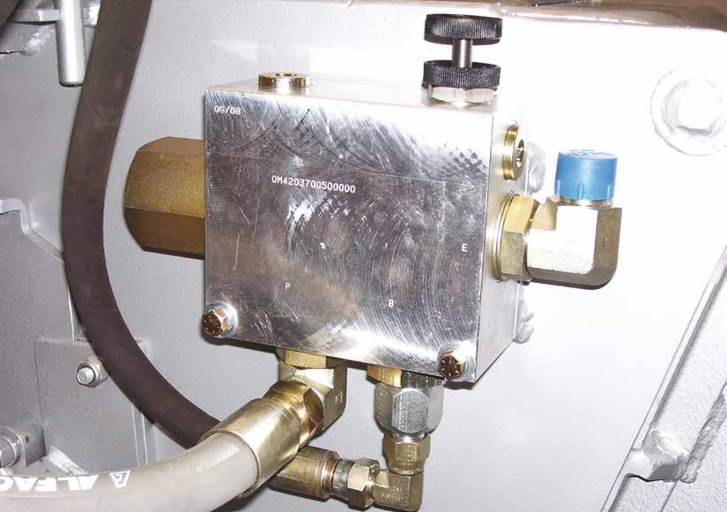
7 CLEANA BUCKET BROOM OPERATION WITH THE SIDE BROOM INSTALLED 4 INSTALLATION AND OPERATING INSTRUCTIONS 3. Operate the machine at medium RPM. If excessive dust is being raised, reduce brush speed via lower RPM s and travel slower. 4. When the bucket requires emptying, stop rotation of the brushes, lift loaders arms and tilt bucket forward so the Cleana Bucket Broom lid swings away from the bucket. 1. The optional side broom attachment has been installed and setup at the factory with your Cleana Bucket Broom, you will not need to make any modifications to the installation. 2. There are two optional side sweeper kits for Cleana Bucket Brooms. One kit is for the standard flow Cleana Bucket Broom and the other is for the high flow Cleana Bucket Broom. The two kits are different hence carry different part numbers. THE HIGH FLOW KIT PART NUMBER BR (DEPICTED ON PAGE 5) is set up at the factory to handle a continuous hydraulic flow rate of 60 litres per minute which equates to a side broom rotational speed of 300 rpm.the side sweeper motor will however handle a maximum continuous hydraulic flow of 75 litres per minute which will equate to a side broom rotational speed of 375 rpm. Flow to the side sweeper motor is controlled by the adjustment of the black knob on the pressure compensated flow control valve shown in the photo on page 10). THE STANDARD FLOW KIT PART NUMBER BR (DEPICTED ON PAGE 5) cannot be set up at the factory as no pressure compensated flow control valve is provided on this kit. It is the responsibility of the end user to ensure that the hydraulic flow to the side sweeper broom maintains a recommended continuous flow of 60 litres per minute which equates to a side broom rotational speed of 300 rpm and does not operate at a higher flow rate than 75 litres per minute which will equate to a side broom rotational speed of 375 rpm. WARNING: THE SPEED OF THE SIDE BROOM HAS TO BE SET BY A PERSON OTHER THAN THE OPERATOR, WHEN CARRYING OUT THIS PROCEDURE EXTREME CARE MUST BE TAKEN DUE TO THE ROTATING BRUSH. 3. Your side broom is now ready for use in sweeping area s such a s kerbs, alongside walls or ledges or where close access is restricted due to motor and cover protrusion. 4. On the pressure compensated flow control valve, the black knob on the valve should not be adjusted with the side sweeper broom in the vertical position. 7
8 4 INSTALLATION AND OPERATING INSTRUCTIONS DANGER: DO NOT OPERATE THE SIDE SWEEPER BROOM WITH THE ARM IN THE VERTICAL POSITION. REMOVAL AND STORAGE 1. Set the attachment on the ground and follow the standard shut down procedure in your loader operators manual. 2. With the loader OFF, disengage the attachment lock pins, release hydraulic pressure from the auxiliary hydraulic system and disconnect the hydraulic couplers from the loader. 3. Start the machines engine and make sure that the lift arm is lowered and in contact with the loader frame. 4. Roll the attachment mechanism forward and slowly back up until the attachment is free from the machine. 5. Remove and store the attachment in a dry and protected place. Leaving the Cleana Bucket Broom and Side Broom Attachment outside will materially shorten its life. WHEN ATTACHMENTS NOT ON PARENT MACHINE: It is a requirement of the Australian Work place Health and Safety act 1995 that safe systems of work are employed when handling any attachments. Complete compliance with Work place Health and Safety issues is compulsory and all due care and attention must be observed at all times in any method of moving, transporting or storing any such device when not attached to a parent machine. We recommend attachments are well secured when being moved or in transit and furthermore prior to moving, storing, loading/unloading or parking it is suggested that the attachment is strapped/secured to a pallet or enclosed in a suitable container to minimise any movement or loss of the load during such activity. NO responsibility for loss or damage to persons or property in any regard can be attributed to Digga. TRANSPORTING THE ATTACHMENT 1. Follow all federal, state and local regulations when transporting the unit on public roads. 2. Use extra care when loading or unloading the machine onto a trailer or truck. Disconnect hydraulic couplers during transportation. 5 MAINTENANCE The key feature of your Digga Cleana Bucket Broom is low maintenance. It contains no user serviceable parts, unauthorised disassembly will void warranty. SAFETY FIRST!! READ AND UNDERSTAND THE SAFETY INSTRUCTIONS BEFORE BEGINNING ANY BROOM MAINTENANCE. BEFORE FIRST USE Inspect the attachment for shipping damage. If damage does exist, do not operate until the damaged parts have been replaced or repaired. 8 PM B - Cleana Bucket Broom Operator s Manual - October 2016


9 BEFORE EACH USE Make sure that all nuts and bolts are in place and properly tightened. Make sure that all other fasteners are in place and are performing their specified function. Make sure that all hydraulic fittings are tightened and that there are no leaks in any fittings or hoses. Make sure that all safety signs are in place, are clean, and are legible. (SEE THE SAFETY SIGN SECTION) Check for wear and tear on Pins, linkages, cutting edges and replace any damaged parts and excessively worn parts. Use only manufacturer recommended replacement parts. Other parts may be substandard in fit and quality. Always wear safety goggles or glasses when inspecting equipment. Grease all grease nipples at the start of the day. EVERY 10 HOURS OF USE Check the Broom axle is inline and adjust as nescessary. Always wear safety goggles or glasses when inspecting equipment. WARNING! If injured by injected fluid, see a doctor at once. If your doctor is not familiar with this type of injury, ask him to research it immediately to determine proper treatment. BRUSH ADJUSTMENT CARDBOARD HYDRAULIC HOSE OR FITTING MAGNIFYING GLASS 5 MAINTENANCE Escaping fluid under pressure can have sufficient force to penetrate the skin causing serious personal injury. Fluid escaping from a very small hole can be almost invisible. Use a piece of cardboard or wood, rather than hands to search for suspected leaks. Keep unprotected body parts, such as face, eyes, and arms as far away as possible from a suspected leak. Flesh injected with hydraulic fluid may develop gangrene or other permanent disabilities. Remove handle pin, twist handle, and replace pin. Readjust the axle to the correct height using both handle adjusters. Return handles to their original position. TIP: Set the height of the brush so the bottom of the brush is approxiamately 30mm lower than the bucket cutting edge. The brush must be level. 30mm 30mm 9
 HS-000018 - ISO COUPLERS (E) HS-000066 - F/F COUPLERS HOSE D or HOSE E PM-000016-B - Cleana Bucket Broom Operator s Manual - October")
10 G HS F HS HOSE D or HOSE E SUPPLY & RETURN HOSES NOT SHOWN IN PHOTO SUPPLY HOSE PART NUMBER (D) HS ISO COUPLERS (E) HS F/F COUPLERS H HS RETURN HOSE PART NUMBER (D) HS ISO COUPLERS (E) HS F/F COUPLERS HOSE D or HOSE E PM B - Cleana Bucket Broom Operator s Manual - October
11 6 OPTIONAL SIDE BROOM INSTALLATION INSTRUCTIONS There are two ways to get a side sweeper broom. They can be ordered as an optional attachment with the cleana broom at the time the cleana broom is ordered or can be ordered as an optional retrofit kit: OPTION 1: RETROFITTING THE SIDE SWEEPER BROOM. (To standard flow Cleana Brooms) If the Side Sweeper Broom is supplied as a retrofit kit, please take the time to read these installation instructions so that the installation will be completed efficiently and safely. The following steps are required for retrofitting the Side Sweeper Broom attachment to your standard Digga Cleana Broom: 1. POST AUG 2010 BROOMS: The installation of the side sweeper broom attachment is relatively easy as long as these instruction are carefully followed. If your Cleana Broom was manufactured after August 2010 then there will already be nuts welded on the inside of the broom hood. This is to accommodate the 4 x M10 x 40mm long bolts though the flange mount of the side sweeper broom. 2. PRE AUG 2010 BROOMS: If you are fitting a new side sweeper broom to a broom which was manufactured prior to August 2010, mounting holes will have to be drilled into the left hand side of the broom hood. (Use the supplied drilling template part number DE to drill the 4 x Ø11mm holes in the left hand side of the hood). Line up the datum reference point on the drilling template with the datum reference point shown in the photo on page 12. Using the drilling template, proceed to mark and drill the 4 holes in the broom hood as shown on the template. In order to affix the M10 flat washers and nyloc nuts on the inside of the hood, the broom will have to be lifted onto stands in order to gain access to the underside of the unit to hold the nuts whilst the bolts are installed from the outside of the unit (This is only required on Cleana Brooms that were manufactured prior to Aug 2010). Please take heed of the below warning notice. It is for your own safety! WARNING: DO NOT ATTEMPT TO WORK UNDER THE BROOM UNLESS THE BROOM IS SECURELY SUPPORTED AND THE BROOM IS STABLE AND SAFE TO WORK UNDER. DO NOT RELY ON THE SKID-STEER HYDRAULIC PRESSURE TO SUPPORT & HOLD THE BROOM OFF THE GROUND. THE CLEANA BROOM MUST BE RESTING ON TIMBER BLOCKS OR RIGID SUPPORTS. (NOT ROCKS, BRICKS OR BESSA-BLOCKS AS THEY ARE KNOWN TO BREAK). 11

12 NOTE: RETROFIT APPLICATION If the Cleana Broom was manufactured after August 2010, the 4 X ø 11mm holes with M10 weld nuts will be welded into hood. If manufactured prior to August 2010, the 4 holes will need to be drilled. Use the drilling template DE to mark hole position. PM B - Cleana Bucket Broom Operator s Manual - October
13 6 OPTIONAL SIDE BROOM INSTALLATION INSTRUCTIONS DRILLING TEMPLATE - SIDE SWEEPER BROOM MOUNTING DE Drilling Template - Side Sweeper Broom Mounting DATUM REFERENCE POINT DRILL 4 X Ø11MM HOLES IN POSITION SHOWN 13
14 6 OPTIONAL SIDE BROOM INSTALLATION INSTRUCTIONS 3. CONNECTING THE HYDRAULICS ON A SIDE SWEEPER BROOM ONTO A STANDARD FLOW CLEANA BROOM: Disconnect the return hose running from the main hydraulic motor (Port No A-see illustration on page 15) to the skid steer loader. This is one of the two original hoses (part no. HS ) supplied with the broom. The side sweeper broom is supplied with 4 new hoses which need to be installed. The supply hose (Hose E) connected to the port B on the main hydraulic motor does not need to be changed. Connect the Hose A to port A of the hydraulic motor. Hose A is a short hose and is to be connected to Hose C. Hose C is to be connected to the upper positioned port on the hydraulic motor of the side sweeper broom. The port is not identified by any markings or stampings on the hydraulic motor housing. Connect Hose D to the lower port on the hydraulic motor of the side sweeper broom. This port is not identified on the hydraulic motor with any markings or stampings on the hydraulic motor housing. Hose D connects to Hose B via a quick coupler. Then Hose B connects to the quick couplers of the skid steer loader. Remember to pass both the supply Hose E and return Hose B through the hose clamp mounted on the left hand side of the broom as how the hoses were fastened from the factory. (See page 15 for the schematic of hydraulic circuit for the standard flow Cleana Broom.) 4. Connect the hydraulic hoses to the skid steer loader and remove the stands from under the Cleana Broom and perform a stationary test on the Cleana Broom to check for any oil leaks. Ensure that all bystanders are standing a minimum distance of 15m away from the attachment and that all necessary safety precautions are taken into account. OPTION 2: RETROFITTING THE SIDE SWEEPER BROOM. (To High flow Cleana Brooms) The installation of the side sweeper broom attachment is relatively easy as long as these instruction are carefully followed. If your High Flow Cleana Broom was manufactured after August 2010 then there will already be nuts welded on the inside of the broom hood to accommodate the 4 x M10 x 40mm long bolts though the flange mount of the side sweeper broom. If your broom was manufactured prior to Aug 2010 and does not have holes provided for the side sweeper broom flange, then refer to paragraph 2 above to perform the marking and drilling of the side sweeper broom mount. Refer to the photo above and use the supplied drilling template (part number DE ) to mark and drill the holes. (The drilling template is supplied as part of the side sweeper broom retrofit kit.) WARNING: DO NOT ATTEMPT TO WORK UNDER THE BROOM UNLESS THE BROOM IS SECURELY SUPPORTED AND THE BROOM IS STABLE AND SAFE TO WORK UNDER. DO NOT RELY ON THE SKID-STEER HYDRAULIC PRESSURE TO SUPPORT & HOLD THE BROOM OFF THE GROUND. THE CLEANA BROOM MUST BE RESTING ON TIMBER BLOCKS OR RIGID SUPPORTS. (NOT ROCKS, BRICKS OR BESSA-BLOCKS AS THEY ARE KNOWN TO BREAK.) 1. Insert the 4 x M10x 40mm long bolts through the 4 mounting holes in the LHS of the broom housing. See illustration on page Disconnect the two hydraulic hoses which connect to the high flow hydraulic motor of the Cleana Broom. This will free up space and allow better access when fitting the regulating valve. 3. If your High Flow Cleana Broom was manufactured after April 2012 then there will already be 2 x pre-drilled holes with M8 nuts welded PM B - Cleana Bucket Broom Operator s Manual - October
15 6 OPTIONAL SIDE BROOM INSTALLATION INSTRUCTIONS SCHEMATIC OF HYDRAULIC CIRCUIT FOR THE STANDARD FLOW CLEANA BROOM 15

16 NOTE: RETROFIT APPLICATION If the High Flow Cleana Broom was manufactured after April 2012 the 2 X ø 8.5mm holes with M8 weld nuts will be provided. If manufactured prior to April 2012, the 2 holes need to be drilled. Use the drilling template DE to mark the hole position. PM B - Cleana Bucket Broom Operator s Manual - October
17 6 OPTIONAL SIDE BROOM INSTALLATION INSTRUCTIONS DRILLING TEMPLATE - REGULATING VALVE FOR HIGH FLOW APPLICATIONS DE Drilling Template - Regulating Valve for High Flow Applications DRILL 2 X Ø8.5MM HOLES IN POSITION SHOWN DATUM REFERENCE POINT 17
18 6 OPTIONAL SIDE BROOM INSTALLATION INSTRUCTIONS on the inside of the broom hood to accommodate the high flow regulator valve. All high flow Cleana Brooms manufactured prior to April 2012, were not provided with pre-drilled holes and weld nuts and therefore holes will have to be provided by the dealer or end user. Using the supplied template (part number DE ), position the drilling template and proceed to mark and drill the 2 x Ø8.5mm holes in the left hand side of the broom hood. In order to affix the M8 flat washers and nyloc nuts on the inside of the hood, the broom will have to be lifted onto stands in order to gain access to the underside of the unit to hold the nuts whilst the bolts are installed from the outside of the unit. Please take heed of the below warning notice. It is for your own safety! WARNING: DO NOT ATTEMPT TO WORK UNDER THE BROOM UNLESS THE BROOM IS SECURELY SUP- PORTED AND THE BROOM IS STABLE AND SAFE TO WORK UNDER. DO NOT RELY ON THE SKID-STEER HYDRAULIC PRESSURE TO SUPPORT & HOLD THE BROOM OFF THE GROUND. THE CLEANA BROOM MUST BE RESTING ON TIMBER BLOCKS OR RIGID SUPPORTS. (NOT ROCKS, BRICKS OR BESSA-BLOCKS AS THEY ARE KNOWN TO BREAK.) 4. Installing the regulating valve: In the side sweeper broom retrofit kit for the high flow broom is the regulating valve. By this stage your cleana broom has either holes and weld nuts provided in the broom hood or you have already drilled the holes. 5. Mount the regulating valve to the side plate of the broom using the 2 x M8 x 95 long mounting bolts, flat and spring washers and M8 Nyloc nuts. 6. Connect the 2 hoses to the motor of the side sweeper broom as shown in the below schematic illustration as well as photo. Install the T-fitting into the outlet port of the main broom motor and connect the hose. Proceed to connect all the hoses as per the photo and the below schematic. Connect the supply and return hoses of the Side Sweeper Broom as per the below schematic. (See page 19 for schematic of hydraulic circuit for the High Flow Cleana Broom.) 7. Connect the hydraulic hoses to the skid steer loader and remove the stands from under the Cleana Broom and perform a stationary test on the Cleana Broom to check for any oil leaks. Ensure that all bystanders are standing a minimum distance of 15m away from the attachment and that all necessary safety precautions are taken into account. 8. Connect the hydraulic hoses to the skid steer loader and remove the stands from under the Cleana Broom and perform a stationary test on the Cleana Broom to check for any oil leaks. Ensure that all bystanders are standing a minimum distance of 6m away from the attachment and that all necessary safety precautions are taken into account. 9. Setting up the side sweeper broom to optimum brush speed and hydraulic flow. PM B - Cleana Bucket Broom Operator s Manual - October
19 6 OPTIONAL SIDE BROOM INSTALLATION INSTRUCTIONS SCHEMATIC OF HYDRAULIC CIRCUIT FOR THE HIGH FLOW CLEANA BROOM 19
20 6 OPTIONAL SIDE BROOM INSTALLATION INSTRUCTIONS SPECIAL ATTENTIONS FOR USERS: DUE TO DIGGA NOT KNOWING WHAT HIGH FLOW MACHINE EACH CLEANA BROOM WILL BE INSTALLED ON, IT IS THE RESPONSIBILITY OF THE DEALER/CUSTOMER TO ENSURE THAT THE HYDRAULIC FLOW REGULATING VALVE (MOUNTED ON THE LEFT HAND SIDE OF THE BROOM) IS SET TO THE FOLLOWING SPECIFICATIONS. ENSURE THAT THE FLOW THROUGH THE REGULATING VALVE IS SET AT APPROXIMATELY 60 LITRES /MIN WHICH WILL EQUATE TO THE SIDE SWEEPER BROOM ROTATING AT APPROXIMATELY 300 RPM. ENSURE THAT THE MAXIMUM FLOW DOES NOT EXCEED 75 LITRES/MIN. WHICH IS APPROXIMATELY 375 RPM OF THE SIDE SWEEPER BROOM. THE REGULATING VALVE HAS A BLACK PLASTIC ADJUSTMENT KNOB WITH LOCKING ABILITY ON THE TOP OF THE VALVE. IT IS NOT PRESET AT THE DIGGA FACTORY. IT MUST BE SET BY THE DEALER OR END USER. (SEE PHOTO ON PAGE 21) PM B - Cleana Bucket Broom Operator s Manual - October
21 21
22 7 SAFETY - STICKER LOCATION PLACEMENT OR REPLACEMENT OF SAFETY SIGNS 1. Clean the area of application with nonflammable solvent, then wash the same area with soap and water. 2. Allow the surface to fully dry. 3. Remove the backing from the safety sign, exposing the adhesive surface. 4. Apply the safety sign to the position shown in the diagram above and smooth out any bubbles. INSTRUCTIONS Keep all safety signs clean and legible. Replace all missing, illegible or damaged safety signs. Replacement parts for parts with safety signs attached must also have safety signs attached. Safety signs are available from your dealer or from Digga Australia. CLEANA ANGLE BROOM NO ORDER CODE DESCRIPTION QTY 1 DE CAUTION - RIDING ON SWEEPER 2 2 DE CAUTION - ENSURE BYSTANDERS 15M - BRUSHES 1 3 DE DECAL - PINCH POINT 2 4 DE CAUTION - PLEASE READ 15M CLEAR 1 5 DE DIGGA SERIAL TAG 1 6 DE BRUSH DIRECTION 1 7 DE CLEANA BY DIGGA ITEM 1 ITEM 2 ITEM 3 ITEM 4 ITEM 5 ITEM 6 DRIVING DRIVING REVERSE FORWARD 3 5 ITEM 7 BRUSH DIRECTION DE PM B - Cleana Bucket Broom Operator s Manual - October
23 8 SPARE PARTS For further information on spare parts, please contact one of the Digga sales offices below or your closest authorised Digga Dealer WEB: DIGGA HEAD OFFICE - BRISBANE 4 Octal Street, Yatala QLD 4207 PH: DIGGA info@digga.com DIGGA NEW SOUTH WALES Unit 2, 36 Bluett Drive, Smeaton Grange NSW 2567 PH: DIGGA nsw@digga.com DIGGA VICTORIA 27 Metcalf Street, Dandenong, VIC 3175 PH: DIGGA vic@digga.com 23
24 9 TROUBLESHOOTING CLEANA BUCKET BROOM TROUBLE POSSIBLE CAUSE REMEDY Brush does not turn. Does not sweep correctly. Hydraulic oil over heating. Brush wearing quickly. Quick Couplers not engaged properly. Quick Coupler failure. An Obstruction in the hoses. Motor failure. Incorrect brush height adjustment. Worn brush. Brush speed too fast or too slow. Parent machine travel to Slow or too fast. Incorrect brush rotation and or travel direction. Relief valve set too low on parent machine. Restriction in hose or quick coupler. Faulty coupler. Parent machine not equiped with oil cooler or sufficient oil capacity. Brush RPM too high. Incorrect brush adjustment. Brushing highly abrasive material. Check hoses and engage properly. Replace faulty coupler. Remove obstruction. Contact your local Digga Dealer. Check and adjust. Replace brush. Adjust brush R.P.M to suit conditions. Adjust travel speed. Adjust brush rotation and travel speed. Test and set as needed. Inspect and Repair. Inspect and Repair. Stop, allow to cool when it gets hot. Reset or Lower RPM. Check and adjust. Contact your local Digga Dealer. Bucket wear edges wearing quickly. Broom being used at incorrect angle. Adjust broom angle. SIDE SWEEP ACCESSORY Oil Leak. Loose connection. Check. Damage to fittings. Repair or Replace. Damage to hoses. Repair or Replace. Oil leak at motor. Damage to motor. Contact your local Digga Dealer. Blown seal. Contact your local Digga Dealer. Worn Brush. Replace. Not Cleaning properly. Incorrect rotation. Reset flow for correct rotation. Incorrect brush angle. Reset broom to correct angle. Not Rotating. Black knob on regulating valve been screwed all the way in. Unscrew knob, Side Sweeper Broom reaches optimum speed 60LPM. PM B - Cleana Bucket Broom Operator s Manual - October
25 WARRANTY All new Digga products are warranted to be free from defects in materials or workmanship, for a period of twelve (12) months from date of original purchase, which may cause failure under normal usage and service when used for the purpose intended. Digga Australia Ptyt Ltd warrants its equipment for a period of twelve (12) months dating from delivery to the original user. In the event of failure (excluding cable, ground engaging parts such as sprockets, digging chain, bearings, teeth, tamping and demolition heads, blade cutting edges, pilot bits, auger teeth, auger heads ), if after examination, Digga determines failure was due to defective material and/or workmanship, parts only will be repaired or replaced. Digga may request defective product or products be returned prepaid to them for inspection at their place of business or to a location specified by Digga. The warranty will be considered void if the product or any part of the product is modified or repaired in any way not expressly authorized by Digga, or if closed components are disassembled prior to return. Closed components include, but are not limited to: gearboxes, hydraulic pumps, motors, cylinders and actuators. Any goods returned to Digga by the customer under warranty or repair must have all freight charges prepaid for on the customers account. Any claims under this warranty must be made within fifteen (15) days after the Buyer learns of the facts upon which such claim is based. All claims not made in writing and received by Digga outside the time period specified above shall be deemed waived. DAMAGE OR FAILURE THROUGH OPERATOR ABUSE OR NEGLIGENCE VOIDS WARRANTY THIS WARRANTY IS IN LIEU OF ALL OTHER WARRANTIES EXPRESSED OR IMPLIED AND THERE ARE NO WAR- RANTIES OF MERCHANTABILITY OR OF FITNESS FOR A PARTICULAR PURPOSE. IN NO EVENT SHALL DIGGA BE LIABLE FOR CONSEQUENTIAL OR SPECIAL DAMAGE. DIGGA S LIABILITY FOR ANY AND ALL LOSSES AND DAMAGES TO BUYER, RESULTING FROM ANY CAUSE WHATSOEVER, INCLUDING DIGGA S NEGLIGENCE, IR- RESPECTIVE OF WHETHER SUCH DEFECTS ARE DISCOVERABLE OR LATENT, SHALL IN NO EVENT EXCEED THE PURCHASE PRICE OF THE PARTICULAR PRODUCTS WITH RESPECT TO WHICH LOSSES OR DAMAGES ARE CLAIMED, OR, AT THE ELECTION OF DIGGA, THE REPAIR OR REPLACEMENT OF DEFECTIVE OR DAM- AGED PRODUCTS. 25
26 11 SAFETY PRECAUTIONS - GENERAL INFORMATION This section is composed of various warnings and safety tips. Read and learn all the information in this section before you attempt to use your attachment. Also read your machines owner s manual before using your equipment. This knowledge will help you operate your unit safely. Do not take this information lightly, it is presented for your benefit and for the benefit of others working around you. The DIGGA Cleana Bucket Broom receives its power from the Parent Machine through the Auxiliary Valve circuit with Quick Release Couplers normally located on the machine arms near the front. Attaching points on the Cleana Bucket Broom are the same as the bucket attaching points on your machine. If you are in any doubt contact your nearest DIGGA Dealer for assistance. TAKE NOTE! THIS SAFETY ALERT SYMBOL FOUND THROUGHOUT THIS MANUAL IS USED TO CALL YOUR ATTENTION TO INSTRUCTIONS INVOLVING YOUR PERSONAL SAFETY OR OTHERS. FAILURE TO FOLLOW THESE INSTRUCTIONS CAN RESULT IN INJURY OR DEATH. THIS SYMBOL MEANS: ATTENTION! BECOME ALERT! YOUR SAFETY IS INVOLVED! SIGNAL WORDS: Note the use of signal words DANGER, WARNING, and CAUTION with the safety messages. The appropriate signal word for each has been selected using the following guidelines: DANGER: Indicates an imminently hazardous situation, which if not avoided, will result in death or serious injury. This signal word is to be limited to the most extreme situations, typically for machine components which, for functional purposes, cannot be guarded. WARNING: Indicates a potentially hazardous situation, which if not avoided, could result in death or serious injury, and includes hazards that are exposed when guards are removed. It may also be used to alert against unsafe practices. CAUTION: Indicates a potentially hazardous situation, which if not avoided, may result in minor or moderate injury. It may also be used to alert against unsafe practices. TO THE OPERATOR The primary responsibility for safety with this equipment falls to the operator. Make sure that the equipment is operated only by trained individuals that have read and understand this manual. Don t hurry the learning process or take the unit for granted. It is the skill, care, common sense, and good judgement of the operator that will determine how efficiently and safely the job is performed. Know your equipment before you start. Know its capabilities and how to operate all the controls. Visually inspect your equipment before you start, ensure correct assembly and installation of the attachment and never operate equipment that is not in proper working order. Practice the operation of your new attachment and become familiar with the controls and the way it handles on your machine. If there is any portion of this manual or function you do not understand, contact your local authorized dealer or the manufacturer. PM B - Cleana Bucket Broom Operator s Manual - October
27 11 SAFETY PRECAUTIONS - GENERAL INFORMATION 1. Never operate the Attachment without first reading and understanding the entire operator s manual. 2. Do not paint over, remove or deface any safety signs or warning decals on your equipment. 3. Follow all safety decals. Keep them clean and replace them if they become worn, damaged or illegible. 4. Know your equipment inside and out. Know how to operate all controls and know emergency shut down procedures 5. Keep all stepping surfaces, pedals, and controls free from dirt, grease and oil to help avoid injury from slipping or a fall when getting on or off equipment. 6. Operate the attachment only in daylight or sufficient artificial light. 7. Always carry loads close to the ground. Do not step off machine platform with load raised. 8. Turn off engine before performing maintenance. All maintenance can be performed with the machine arms lowered. If lift arms must be left raised for any reason, use a positive lift arm lock to secure the arms in place. Serious damage or personal injury could result from lift arms accidentally lowering. 9. Reduce speed when driving over rough terrain, on a slope, or turning to avoid overturning the machine. 10. Check your work area and know where all utility lines are. Avoid hitting underground or overhead electrical wires, cables, pipes, fence posts, gas lines, etc. 11. Never operate equipment while under the influence of alcohol, prescription drugs or any other form of illegal recreational drugs which could inhibit physical and/or mental capacity. 12. Do not exceed rated operating capacity, as machine may become unstable resulting in loss of control. 13. Always lower the loader arms or machine boom to the ground, shut off the engine and remove the key before getting off the unit. 14. Operators, helpers, and other personnel working near Cleana Bucket Broom must wear steel-toe safety shoes, safety glasses, and hard hats as a minimum. Hearing protection, respirators, and personnel protective clothing will be specified in the site-specific Health and Safety Plan. 15. Do not smoke when refuelling machine. Allow room in the gas tank for expansion. Wipe up any spilt fuel. Secure cap tightly when done. 16. Be alert to others in the work area. Be sure others know when and where you will be working. Make sure no one is behind equipment or within 15 metres of it operating. 17. Loose fitting clothing, long hair, jewellery and equipment which might become entangled in moving equipment are prohibited while working near Cleana Bucket Broom. 18. Cleana Bucket Brooms must be shut down and properly locked-out and tagged before repairs or maintenance is performed. Only properly trained and qualified individuals are permitted to perform repairs and maintenance. 19. Site workers shall not be allowed on/in a Cleana Bucket Broom while it is in operation or the equipment is being moved. 20. Machinery must be shut down and the key removed before being left unattended. 21. Controls must be engaged slowly until hydraulic fluids and the unit are up to operating temperature. This is critical during cold weather. Impact or shock loading of the Cleana Bucket Broom is prohibited. 22. Cleana Bucket Brooms shall be used only for their designed intent and shall not be loaded beyond their rated capacity. Overloading or exceeding the manufacturers specifications will void all warranty. 27
28 11 SAFETY PRECAUTIONS - GENERAL INFORMATION 23. Sharp braking or hoisting is prohibited. 24. Only authorized, properly trained workers will be permitted to operate Cleana Bucket Broom. All unnecessary personnel will stand clear of Cleana Bucket Brooms or devices while they are in operation. 25. The operator shall verbally alert site workers and visually ensure all site workers are clear from dangerous parts of equipment before starting or engaging equipment. 26. Cleana Bucket Broom must be stationary before adding or removing Side Sweep Broom attachment, or making adjustments to the equipment. 27. Cleana Bucket Brooms shall be cleaned only when the mechanism is in neutral and stopped; long-handled shovels shall be used to move debris from the Cleana Bucket Broom. Materials heavier than 10kgs must be moved mechanically or by using at least two people. 28. Operations must be stopped in the event of local thunderstorm, or lightning activity. During operation, weather conditions shall be monitored: operations shall cease during electrical storms or when electrical storms are imminent. WHEN OPERATING THIS PRODUCT IN ACCORDANCE WITH DESIGN INTENTIONS Never use Cleana Bucket Broom on a Loader that is not equipped with a cab or ROPS, and operator restraints (seat belts or equivalent devices). Know your machines safe operating weight limit, and the weight of loaded attachment. Use caution when working close to fences and ditches, or on uneven ground. WHEN ADJUSTING, SERVICING OR REPAIRING THIS PRODUCT Make no modifications to your Cleana Bucket Broom. When making repairs, use only genuine Digga parts for fasteners, hydraulic hoses, or hydraulic fittings, use only properly rated parts. Replacement parts, for parts with safety signs attached, must also have safety signs attached. WHEN MOUNTING THIS PRODUCT TO YOUR MACHINE Refer to the operator s manuals of your machine, and your quick-attach for special or detailed mounting instructions. This product should fit onto the quick-attach Frame or Hitch. If this product does not fit properly, contact your Digga Dealer before operating. Never place any part of your body into the mounting plate, frame, hitch or loader holes. A slight movement of the power unit or this product could cause serious injury. Where Dead Man connections are connected or installed it is illegal to disengage, tamper with or remove them. PM B - Cleana Bucket Broom Operator s Manual - October
29 11 SAFETY PRECAUTIONS - GENERAL INFORMATION WHEN DEALING WITH HYDRAULICS DURING ANY TYPE OF ASSEMBLY, OPERATION, MAINTENANCE, OR OTHER WORK ON OR NEAR THIS PRODUCT Hydraulic fluid under pressure can penetrate the skin and cause serious injury or death. Hydraulic leaks under pressure may not bevisible! If any fluid penetrates the skin, GET IMMEDIATE MEDICAL ATTENTION!! Wear safety glasses, protective clothing, and use a sound piece of cardboard or wood when searching for hydraulic leaks. DO NOT USE YOUR HANDS! Before connecting or disconnecting hydraulic hoses, read your machine or power unit s operator s manual for detailed instructions on connecting and disconnecting hydraulic attachments. Make certain that all parts meet the specifications for this product when installing or replacing hydraulic hoses or fittings. After connecting hydraulic lines: Slowly and carefully raise the loader and cycle the rollback/dump cylinders to check hose clearances and to check for any interference. Operate the hydraulics on this product to check hose clearances and to check for any interference. Make certain that the hoses cannot interfere with or actuate the quick-attach mechanism. Make certain that hoses will not be pinched, or get tangled, in any equipment. Do not lock the auxiliary hydraulics of your power unit in the ON position. Refer to your power unit s operator s manual and this manual for procedures and intervals, then inspect and maintain the entire hydraulic system to insure that the fluid remains clean, that all devices function properly, and that there are no fluid leaks. Always wear safety goggles or glasses when inspecting equipment. WARNING! If injured by injected fluid, see a doctor at once. If your doctor is not familiar with this type of injury, ask him to research it immediately to determine proper treatment. CARDBOARD HYDRAULIC HOSE OR FITTING MAGNIFYING GLASS Escaping fluid under pressure can have sufficient force to penetrate the skin causing serious personal injury. Fluid escaping from a very small hole can be almost invisible. Use a piece of cardboard or wood, rather than hands to search for suspected leaks. Keep unprotected body parts, such as face, eyes, and arms as far away as possible from a suspected leak. Flesh injected with hydraulic fluid may develop gangrene or other permanent disabilities. For additional safety information please see Risk Management booklet. To obtain a copy contact Digga Head Office on
30 Australian Designed and Manufactured PM B - Cleana Bucket Broom Operator s Manual - October PM B
OPEN AND REMOVABLE FACE BUCKET BUCKET BROOM OPERATORS & PARTS MANUAL
 OPEN AND REMOVABLE FACE BUCKET BUCKET BROOM OPERATORS & PARTS MANUAL 1 PM-000082 PM-000082 - Open and Removable Face Bucket Broom - May 2011 1 TO THE PURCHASER THANK YOU Congratulations on the purchase
CLEANA BUCKET BROOM OPERATOR S MANUAL PM C
 CLEANA BUCKET BROOM OPERATOR S MANUAL PM-000016-C 2 TO THE PURCHASER Congratulations on the purchase of your new DIGGA Cleana Bucket Broom! This product was carefully designed and manufactured to give
1 To the Purchaser THANK YOU
 1 THANK YOU 1 To the Purchaser Congratulations on the purchase of your new DIGGA product! This product was carefully designed and manufactured to give you years of dependable service. Only minor maintenance
Talet Equipment International Ltd. Sand Kicker
 Talet Equipment International Ltd. Sand Kicker Parts & Operators Manual P.O. Box 35 Strathmore AB Canada TP K3 www.taletattachments.com sales@taletattachments.com Toll Free -888-37-5878 Fax -403-934-304
1 TO THE PURCHASER TABLE OF CONTENTS SERVICE & PREPARATION... 5
 SAFETY ALERT SYMBOL This is the Safety Alert Symbol used by this industry. This symbol is used to warn of possible injury. Be sure to read all warnings carefully. They are included for your safety and
OPERATORS & PARTS MANUAL
 OPERATORS & PARTS MANUAL CLEANA ANGLE BROOM PM-000072-A THANK YOU Congratulations on the purchase of your new DIGGA product! This product was carefully designed and manufactured to give you years of dependable
PM Mini Slasha - MARCH 2015 REV D
 PM-000054 Mini Slasha - MARCH 2015 REV D 2 Congratulations on the purchase of your new DIGGA Mini Slasha! This product was carefully designed and manufactured to give you years of dependable service. To
HYDRAULIC RETROFIT KIT FOR MINI POWER RAKE
 HYDRAULIC RETROFIT KIT FOR MINI POWER RAKE 1 1 TO THE PURCHASER THANK YOU Congratulations on the purchase of your new hydraulic conversion kit for your DIGGA Mini Power Rake! This product was carefully
1 TO THE PURCHASER THANK YOU ABOUT THIS MANUAL
 PM-000041-F 2 PM-000041-F Diggalign Operators Manual - August 2015 1 TO THE PURCHASER THANK YOU Congratulations on the purchase of your new DIGGA product! This product was carefully designed and manufactured
TELESCOPIC PILING & DRILLING EXTENSION AUSTRALIA OPERATORS MANUAL PM
 TELESCOPIC PILING & DRILLING EXTENSION AUSTRALIA OPERATORS MANUAL PM-000134 1 1 TABLE OF CONTENTS 1 TABLE OF CONTENTS... 2 2 TO THE PURCHASER... 3 3 SERVICE & PREPARATION FOR USE... 4 4 SAFETY PRECAUTIONS
ELECTRICAL KIT - TC PM
 ELECTRICAL KIT - TC-000013 PM-000080 1 TO THE PURCHASER Congratulations on the purchase of your new DIGGA Electrical Kit! This product was carefully designed and manufactured to give you years of dependable
OPERATOR S AND PARTS MANUAL PALLET FORKS. Part Number: MODEL NUMBER: Rev. 4
 OPERATOR S AND PARTS MANUAL PALLET FORKS SERIAL NUMBER: Manual Number: OM642 Part Number: 75542 MODEL NUMBER: Rev. 4 800-456-7100 I www.paladinlcg.com 503 Gay Street, Delhi, IA 52223, United States of
Talet Equipment International Ltd. Sanding Auger Bucket
 Talet Equipment International Ltd. Sanding Auger Bucket Parts & Operators Manual P.O. Box 35 Strathmore AB Canada TP K3 www.taletattachments.com sales@taletattachments.com Toll Free -888-37-5878 Fax -403-934-304
TELESCOPIC PILING & DRILLING EXTENSION NORTH AMERICA OPERATORS MANUAL PM B 1
 TELESCOPIC PILING & DRILLING EXTENSION NORTH AMERICA OPERATORS MANUAL PM-000120-B 1 WARNING CALIFORNIA PROPOSITION 65 WARNING This product contains chemicals known to the State of California to cause cancer
HAND HELD ANCHOR DRIVE
 HAND HELD ANCHOR DRIVE HH-6K - MM-10K OPERATORS MANUAL PM-000127 1 2 PM-000127-Hand Held Anchor Drive Operators Manual - September 2016 1 CRITICAL INFORMATION - SERVICE INTERVALS CRITICAL - DO NOT CONNECT
AUGER DRIVES PDD - PD50 OPERATORS & PARTS MANUAL
 AUGER DRIVES PDD - PD50 OPERATORS & PARTS MANUAL 1 PM-000002 - PDD-PD50 Operators Manual - February 2013 THANK YOU 1 To the Purchaser Congratulations on the purchase of your new DIGGA product! This product
OPERATOR'S & PARTS MANUAL
 1. OPERATOR'S & PARTS MANUAL FOR MINI TILT ATTACH PLATE INSTRUCTIONS NUMBER: 76214 1.888.888.1085 I www.spartanequipment.com Joppa, MD 21085 United States of America 2. TILT ATTACH ASSEMBLY 10522 3-7 -06
Mulcher Operators Manual
 Mulcher Operators Manual Skid Pro Attachments PO Box 982 Alexandria, MN 56308 October 2015 1 2 Contents 1. Introduction And Warranty... 4 1.1 Introduction... 4 1.2 Warranty... 4 2. Component Identification...
Talet Equipment International Ltd.
 Talet Equipment International Ltd. Postmaster and/or Slab Blaster Parts & Operators Manual P.O. Box 2351 Strathmore AB Canada T1 P 1 K3 www.taletattachments.com sales@taletattachments.com Toll Free 1-888-31
BUCKET SWEEPER OPERATORS & PARTS MANUAL 2852 & 3174 SERIES
 OM628 BUCKET SWEEPER OPERATORS & PARTS MANUAL 2852 & 3174 SERIES MODEL 12002-5 FOOT WIDE X 24 INCH DIAMETER (SKID-STEER) MODEL 12004-6 FOOT WIDE X 24 INCH DIAMETER (SKID-STEER) MODEL 12017-6 FOOT WIDE
SERIAL NUMBER: Manual Number: Part Number: MODEL NUMBER: Date: November 23, 2005
 OPERATOR S & PARTS MANUAL 3.00-4.00 CUBIC YARD BUCKETS SERIAL NUMBER: Manual Number: 76839 Part Number: 76839 MODEL NUMBER: Date: November 3, 005 800-9-981 I www.paladinbrands.com P.O. Box 66, Delhi, IA
4IN1 BUCKET & 3RD SERVICE HYDRAULIC KIT JOHN DEERE 4049M TRACTOR OPERATOR S MANUAL PM
 4IN1 BUCKET & 3RD SERVICE HYDRAULIC KIT JOHN DEERE 4049M TRACTOR OPERATOR S MANUAL PM-000160 1 2 PM-000160-4in1 Bucket & 3RD SERVICE HYDRAULIC KIT for JOHN DEERE 4049M TRACTOR Operators Manual - February
INSTALLATION INSTRUCTIONS FOR HD TILT ATTACH ASSEMBLY
 INSTALLATION INSTRUCTIONS FOR HD TILT ATTACH ASSEMBLY PM-000034-A OCTOBER 2017 THIS PAGE IS INTENTIONALLY BLANK PM-000034-A OCTOBER 2017 TABLE OF CONTENTS PREFACE... 2 SAFETY PRECAUTIONS SAFETY STATEMENTS...
Prime Attachments & Custom Fab Brush Mower Owners/Operators Manual
 Prime Attachments & Custom Fab Brush Mower Owners/Operators Manual The operator is responsible for the safe operation and maintenance of the machine. It is important that anyone who uses the machine is
SERIAL NUMBER: Manual Number: Part Number: MODEL NUMBER: Date: March 12, 2007
 OPERATOR S & PARTS MANUAL TREE BOOM SERIAL NUMBER: Manual Number: 76817 Part Number: 76817 MODEL NUMBER: Date: March 12, 2007 800-922-2981 I www.paladinbrands.com P.O. Box 266, Delhi, IA 52223-0266, United
Trench Filler for Compact Utility Loaders
 Form No. 3353-608 Rev A Trench Filler for Compact Utility Loaders Model No. 22472 260000001 and Up Operator s Manual Register your product at www.toro.com Original Instructions (EN) Contents Page Introduction................................
Boring Unit Sitework Systems Attachment
 FORM NO. 6 Boring Unit Sitework Systems Attachment Model No. 0 89000 & Up Operator s Manual English (CE) Contents Page Introduction................................. Safety......................................
OPERATORS MANUAL SAFETY & WARRANTY SECTION
 OPERATORS MANUAL SAFETY & WARRANTY SECTION KMW Ltd. 198 N. Hwy 281 Great Bend, Kansas 67530 800 445-7388 Fax 620 793-6737 ïïïkâãïäç~çéêëkåçã SAFETY FIRST This symbol, the industry s Safety Alert Symbol,
MINI BIGFOOT TRENCHER OPERATORS MANUAL PM A
 MINI BIGFOOT TRENCHER OPERATORS MANUAL 1 PM-000042-A 2 PM-000042-A Mini Bigfoot Trencher Operators Manual - January 2016 1 CRITICAL INFORMATION - SERVICE INTERVALS CRITICAL - DO NOT CONNECT OR OPERATE
WARNING this attachments capacity changes depending on the Skid Steer Loader it is hooked up to. CAPACITY AT 24 LOAD CENTER
 SKID STEER FORKLIFT ATTACHMENT Any piece of equipment can be dangerous if not operated properly. YOU are responsible for the safe operation of this equipment. The operator must carefully read and follow
W & A 12 ROW TOP LEVELING STACKER LEVEL BANDER
 W & A 12 ROW TOP LEVELING STACKER LEVEL BANDER NO. 3640 OPERATOR S MANUAL TO THE OWNER: Congratulations on your purchase of a new W & A Top Leveling Stacker Level Bander. Your selection is an indication
W & A 12 ROW TOP LEVELING STACKER LEVEL BANDER
 W & A 12 ROW TOP LEVELING STACKER LEVEL BANDER NO. 3640 OPERATOR S MANUAL TO THE OWNER: Congratulations on your purchase of a new W & A Top Leveling Stacker Level Bander. Your selection is an indication
MK AUGERS POWER SWING KIT ASSEMBLY & OPERATION MANUAL
 MK AUGERS POWER SWING KIT ASSEMBLY & OPERATION MANUAL Read this manual before using product. Failure to follow instructions and safety precautions can result in serious injury, death, or property damage.
GRAPPLE GRAPPLE INTRODUCTION. Product Manual & Installation Kit. Index: Werk-Brau Co., INC 2800 Fostoria RD PO Box 545 Findlay, Ohio 45839
 Product Manual & Installation Kit GRAPPLE Werk-Brau Co., INC 2800 Fostoria RD PO Box 545 Findlay, Ohio 45839 Ph: 1-800-537-9561 Fax: 419-422-7207 www.werk-brau.com This instruction manual describes the
OPERATOR S AND PARTS MANUAL BB42 BUCKET SWEEPER
 OPERATOR S AND PARTS MANUAL BB42 BUCKET SWEEPER SERIAL NUMBER: MODEL NUMBER: Manual Number: OM686 Part Number: 75586 Rev. 800-456-7100 I www.paladinattachments.com 503 Gay Street, Delhi, IA 52223, United
40 & 48 TILLERS OPERATOR S AND PARTS MANUAL. Part Number: MODEL NUMBER: Rev. 4
 40 & 48 TILLERS OPERATOR S AND PARTS MANUAL SERIAL NUMBER: Manual Number: OM637 Part Number: 75537 MODEL NUMBER: Rev. 4 800-456-7100 I www.paladinlcg.com 503 Gay Street, Delhi, IA 52223, United States
LOG CHOP. Hydraulic Wood Guillotine. Owners Illustrated Instruction Book & Parts List
 LOG CHOP Hydraulic Wood Guillotine Owners Illustrated Instruction Book & Parts List Grovebury Road, Leighton Buzzard, Bedfordshire. LU7 4UX. UK. Tel:01525 375157. Fax:01525 385222. Email: enquires@brownsagricultural.co.uk
BEFCO. Operator s Manual POST HOLE DIGGER ACCESSORIES DOWN FORCE KIT. PHD-002 (fits models MOLE 300 & 400) PHD-005 (fits model MOLE 200) HOOKUP STAND
 PHD-005 (fits model MOLE 200) HOOKUP STAND") BEFCO Operator s Manual POST HOLE DIGGER ACCESSORIES DOWN FORCE KIT PHD-00 (fits models MOLE 300 & 400) PHD-005 (fits model MOLE 00) HOOKUP STAND 009-985 (fits models MOLE 00, 00, 300 & 400) POSITIONING
BEFCO Operator s Manual POST HOLE DIGGER ACCESSORIES DOWN FORCE KIT PHD-00 (fits models MOLE 300 & 400) PHD-005 (fits model MOLE 00) HOOKUP STAND 009-985 (fits models MOLE 00, 00, 300 & 400) POSITIONING
485 BACKHOE PARTS MANUAL
 85 BACKHOE PARTS MANUAL SERIAL NUMBER: Manual Number: PM08 Part Number: 5608 MODEL NUMBER: Rev. 800-56-00 I www.paladinlcg.com 50 Gay Street, Delhi, IA 5, United States of America 06 --0- Limited Warranty
610 BUSHEL MANURE SPREADER
 610 BUSHEL MANURE SPREADER RODA MANUFACTURING 1008 LOCUST ST. HULL, IA. 51239 Art s-way Manufacturing 712-439-2366 Co., Inc. Hwy 9 West - PO Box 288 WWW.RODAMFG.COM Armstrong, IA. 50514 U.S.A 2 INTRODUCTION
Operator s Manual. Go Galvanized! YOU'RE ALWAYS AHEAD...WITH A MODERN BEHIND.
 fall 2010 3pt & quick attach Bale spears & 3pt bale carrier Operator s Manual YOU'RE ALWAYS AHEAD...WITH A MODERN BEHIND. 318-1006-i 318-1005-i 020-1500 020-1502 P.O. Box 790 Beaumont, Tx 77704 409.833.2665
SERIAL NUMBER: Manual Number: Part Number: MODEL NUMBER: Date: November 23, 2005
 OPERATOR S & PARTS MANUAL BALE FORK - 8 SMALL BALES SERIAL NUMBER: Manual Number: 76801 Part Number: 76801 MODEL NUMBER: Date: November 23, 2005 800-922-2981 I www.paladinbrands.com P.O. Box 266, Delhi,
Mini Skid Steer Training
 Safe Operating Practices Mini Skid Steer Training This product is capable of amputating hands and feet. Always follow all safety instructions to avoid serious injury or death. Engine exhaust contains carbon
Operator s Manual. Nitro 1000 Nitro 1000X. Nitro 750 Nitro 750X. September REV0
 Operator s Manual Nitro 750 Nitro 750X Nitro 1000 Nitro 1000X September.27.2018REV0 Table of Contents Introduction...3 Safety.....4 Equipment Requirements......5 What You Have Received. 5 Serial Number...6
ROTARY BRUSH CUTTERS THE LEADER OF THE PACK OWNER/OPERATOR SAFETY & INSTRUCTION MANUAL
 72 M-AX ROTARY BRUSH CUTTERS THE LEADER OF THE PACK OWNER/OPERATOR SAFETY & INSTRUCTION MANUAL CONTENTS Page 1. Introduction..................................2 2. Safety Instructions...........................3-4
MODEL HD99 HYDRAULIC ONE MAN TOWABLE EARTHDRILL
 DO NOT THROW AWAY IMPORTANT MANUAL MODEL HD99 HYDRAULIC ONE MAN TOWABLE EARTHDRILL Operators Manual GROUND HOG, INC. P.O.BOX 290 San Bernardino, CA. 92402 Phone (909) 478-5700 Fax (909) 478-5710 E-mail:
LP1207 LP1208 LP1210 LAND PLANES LP12_5TL15788_06/10
 LP1207 LP1208 LP1210 O P E R A T O R ' S M A N U A L LAND PLANES LP12_5TL15788_06/10 TO THE DEALER: Assembly and proper installation of this product is the responsibility of the Frontier dealer. Read manual
BEFORE YOU START!! Read the safety messages on the implement as shown in your manual. Observe the rules of safety and common sense!
 To the Owner/Operator/Dealer All implements with moving parts are potentially hazardous. There is no substitute for a cautious, safe-minded operator who recognizes the potential hazards and follows reasonable
OPERATOR S AND PARTS MANUAL POWER SIDE DISCHARGE (PSD) BUCKETS SAND & SAWDUST
 BUCKETS SAND & SAWDUST") OPERATOR S AND PARTS MANUAL POWER SIDE DISCHARGE (PSD) BUCKETS SAND & SAWDUST 10714 SERIAL NUMBER: Manual Number: 51-10038 Part Number: 10714 & 10715 MODEL NUMBER: Rev. 3 800-456-7100 I www.paladinattachments.com
OPERATOR S AND PARTS MANUAL POWER SIDE DISCHARGE (PSD) BUCKETS SAND & SAWDUST 10714 SERIAL NUMBER: Manual Number: 51-10038 Part Number: 10714 & 10715 MODEL NUMBER: Rev. 3 800-456-7100 I www.paladinattachments.com
Backhoe for Dingo Compact Utility Loaders
 Form No. 50-5 Backhoe for Dingo Compact Utility Loaders Model No. 60 000000 & Up Operator s Manual Original Instructions (EN/GB) Contents Page Introduction................................. Safety......................................
SERIAL NUMBER: Manual Number: Part Number: & Rev. 3 MODEL NUMBER: Joppa, MD /9/14
 SERIAL NUMBER: MODEL NUMBER: Manual Number: 51-10038 Part Number: 10714 & 10715 Rev. 3 1.888.888.1085 www.spartanequipment.com Joppa, MD 21085 1/9/14 Notes TABLE OF CONTENTS INTRODUCTION...2 GENERAL INFORMATION...
Update Manual. Manufacturing, Inc. 7 & 10 End Wheel No-Till Clutch Linkage. P.O. Box 218 Assaria, Kansas Effective 5/3/ M
 Update Manual 7 & 10 End Wheel No-Till Clutch Linkage Manufacturing, Inc. P.O. Box 218 Assaria, Kansas 67416 Effective 5/3/96 152-156M General Information General Information Important Notice Great Plains
OPERATOR S AND PARTS MANUAL BC60, BC72 & BC78 BRUSH CUTTERS
 OPERATOR S AND PARTS MANUAL BC60, BC72 & BC78 BRUSH CUTTERS UNIVERSAL SKID STEER APPLICATIONS SERIAL NUMBER: Manual Number: OM636 Part Number: 75536 MODEL NUMBER: Rev. 9 800-456-7100 I www.paladinattachments.com
Instruction Manual. Single Acting Hydraulic Aluminium Pull Cylinders RAP Series. Maximum Operating Pressure 700 bar
 Single Acting Hydraulic Aluminium Pull Cylinders RAP Series Maximum Operating Pressure 700 bar ABSOLUTE EQUIPMENT PTY LTD 2/186 Granite Street, GEEBUNG QLD 4034 Australia sales@absoluteequipment.com.au
Multi-Purpose Tool Sitework Systems Attachment
 FORM NO. 22 648 Multi-Purpose Tool Sitework Systems Attachment Model No. 2242 89000 & Up Operator s Manual English (CE) Contents Page Introduction................................. 2 Safety......................................
ROTARY AXE OPERATOR S MANUAL
 ROTARY AXE OPERATOR S MANUAL PM-000101-B OCTOBER 2017 THIS PAGE IS INTENTIONALLY BLANK READ ENTIRE OPERATOR'S & PARTS MANUAL BEFORE OPERATING! DANGER! ROTATING BLADE HAZARD! STAY BACK! OBJECTS CAN BE THROWN!
OPERATOR S AND PARTS MANUAL BALE HUGGER. Part Number: LAF1960 MODEL NUMBER: Rev. 2
 OPERATOR S AND PARTS MANUAL BALE HUGGER SERIAL NUMBER: Manual Number: MR25616 Part Number: LAF1960 MODEL NUMBER: Rev. 2 800-456-7100 I www.paladinlcg.com 503 Gay Street, Delhi, IA 52223, United States
Instruction Manual. Single Acting, Pancake, Locking Collar Hydraulic Cylinders RPLC Series. Maximum Operating Pressure 700 bar
 Single Acting, Pancake, Locking Collar Hydraulic Cylinders RPLC Series Maximum Operating Pressure 700 bar ABSOLUTE EQUIPMENT PTY LTD 2/186 Granite Street, GEEBUNG QLD 4034 Australia sales@absoluteequipment.com.au
APCO CRF-100A RUBBER FLAPPER SWING CHECK VALVES
 APCO CRF-100A RUBBER FLAPPER SWING CHECK VALVES Instruction D12043 June 2016 DeZURIK Instructions These instructions provide installation, operation and maintenance information for APCO CRF-100A Rubber
BEFCO. Operator s Manual BABY HOP & HOP FERTILIZER SPREADERS ACCESSORIES SIDE ROW DISCHARGE. AA4-120 (fits models Hop 209 & 212) DEFLECTOR
 DEFLECTOR") BEFCO Operator s Manual BABY HOP & HOP FERTILIZER SPREADERS ACCESSORIES SIDE ROW DISCHARGE AA-0 (fits models Hop 09 & ) DEFLECTOR AA-0 (fits models Baby Hop 0 & 06) 009-95 (fits models Hop 0 & 06) 009-968
BEFCO Operator s Manual BABY HOP & HOP FERTILIZER SPREADERS ACCESSORIES SIDE ROW DISCHARGE AA-0 (fits models Hop 09 & ) DEFLECTOR AA-0 (fits models Baby Hop 0 & 06) 009-95 (fits models Hop 0 & 06) 009-968
MAGNUM MULCHER MM36E SERIES II OPERATOR S MANUAL
 MAGNUM MULCHER MM36E SERIES II OPERATOR S MANUAL PM-000155 OCTOBER 2017 THIS PAGE IS INTENTIONALLY BLANK PM-000155 OCTOBER 2017 READ ENTIRE OPERATOR'S & PARTS MANUAL BEFORE OPERATING! DANGER! ROTATING
Backhoe for Compact Utility Loaders
 Form No. 54-4 Rev A Backhoe for Compact Utility Loaders Model No. 6 6000000 and Up Operator s Manual Register your product at www.toro.com. Original Instructions (EN) Contents Page Introduction.................................
OWNER S OPERATING MANUAL
 OWNER S OPERATING MANUAL MIG 100 GASLESS WELDER TABLE OF CONTENTS Page Safety instructions 3-4 MIG Welders 5 Welder Information 5 Gasless welder set up 6 Operation 6-10 Troubleshooting Guide 11-12 Spare
Operator's Manual. VC-60 & VC-60 Plus Harper Industries, Inc. 7/03 Part No
 Operator's Manual VC-60 & VC-60 Plus 2003 Harper Industries, Inc. 7/03 Part No. 970066 Thank you for purchasing a Harper/Goossen Verti-Cutter. As with all Harper/Goossen products, the Harper/Goossen Verti-Cutter
LEWIS WINDROWER OWNER / OPERATOR MANUAL
 LEWIS WINDROWER OWNER / OPERATOR MANUAL MODEL # WR-1 WINDROWER Manufactured by: LEWIS BROTHERS MANUFACTURING, INC. Post Office Box 146 Baxley, GA 31513 Tel: (912) 367-4651 Fax: (912) 367-3958 2-21-14 1
Manifold w/ Needle Valve Instruction Manual
 MODELS: MFC2 & MFC4 Manifold w/ Needle Valve Instruction Manual SFA Companies 10939 N. Pomona Ave. Kansas City, MO 64153 Tel: 888-332-6419 - Fax: 816-448-2142 E-mail: sales@bvahydraulics.com Website: www.bvahydraulics.com
SNOWBLADE OPERATOR S AND PARTS MANUAL SERIAL NUMBER: MODEL NUMBER:
 OPERATOR S AND PARTS MANUAL SNOWBLADE SERIAL NUMBER: MODEL NUMBER: Manual Number: MR35537 Models: 11460, 11472, 11484, and 11496; 11584, 11596, 11508, 11520, 11532 and 11544; LAF5784, LAF5796, LAF5708,
OPERATION MANUAL DBW Bale Wagon DFW Feeder Wagon
 OPERATION MANUAL DBW Bale Wagon DFW Feeder Wagon To the Owner/Operator/Dealer All implements with moving parts are potentially hazardous. There is no substitute for a cautious, safe-minded operator who
OPERATOR S MANUAL GROUND SHARK STANDARD DUTY BRUSH CUTTER
 OPERATOR S MANUAL GROUND SHARK STANDARD DUTY BRUSH CUTTER SERIAL NUMBER: Manual Number: OM834 Part Number: 75734 MODEL NUMBER: Rev. 4 800-456-7100 I www.paladinattachments.com 503 Gay Street, Delhi, IA
Planting Components. Operator s/parts Manual. Row Cleaner VIII. Terra-Tine
 Operator s/parts Manual Terra-Tine Row Cleaner VIII Planting Components! Read the operator s manual entirely. When you see this symbol, the subsequent instructions and warnings are serious - follow without
LOG SPLITTER. Heavy Duty PTO Driven. Owners Illustrated Instruction Book & Parts List
 LOG SPLITTER Heavy Duty PTO Driven Owners Illustrated Instruction Book & Parts List Grovebury Road, Leighton Buzzard, Bedfordshire. LU7 4UX. UK. Tel:01525 375157. Fax:01525 385222. Email: enquires@brownsagricultural.co.uk
Log Splitter. Owner/Operator Manual. Models HCWP1-26
 Log Splitter Owner/Operator Manual Models HCWP1-26 SAFETY..........................2 SAFETY WARNING SYMBOL.........3 SAFETY RULES.................. 4-5 SPECIFICATIONS................. 6 CONTROLS AND FEATURES.......
OPERATIONS MANUAL LEVER CHAIN HOIST
 OPERATIONS MANUAL LEVER CHAIN HOIST IMPORTANT SAFETY INFORMATION Please read, understand and follow all safety information contained in these instructions prior to the use of this hoist. Retain these instructions
Post Driver Attachment
 Attachment (Shown with Optional Power Cell Rotator) Models - 600, 850 Safety Instructions This safety alert symbol indicates important safety messages in this manual. When you see this symbol, carefully
OPERATOR S AND PARTS MANUAL ROOT RAKE
 OPERATOR S AND PARTS MANUAL ROOT RAKE SERIAL NUMBER: MODEL NUMBER: Manual Number: OM711 Part Number: 75611 Rev. 800-456-7100 I www.paladinlcg.com 503 Gay Street, Delhi, IA 52223, United States of America
POST HOLE DIGGER. Operation, Service & Parts Manual For Models D20 & D40. FORM: D20_40DigRev.QXD
 POST HOLE DIGGER Operation, Service & Parts Manual For Models D20 & D40 FORM: D20_40DigRev.QXD September 2006 Revised August 2009 TABLE OF CONTENTS Introduction.............................1 Preparation..............................2
Excavator Forks. Introduction. Important Notes. Key Benefits. User Guide
 User Guide Excavator Forks Introduction The Conquip Excavator Forks attachment is designed to enable an excavator to lift palletised material. This is especially useful if space is restricted and budget
ABSOLUTE EQUIPMENT PTY LTD
 Manual Hydraulic Toe Jack Model DTJ Series ABSOLUTE EQUIPMENT PTY LTD 2/186 Granite Street, GEEBUNG QLD 4034 Australia sales@absoluteequipment.com.au Phone: +61 7 3865 4006 Fax: +61 7 3102 6288 This is
Operator s/parts Manual
 Operator s/parts Manual 3-Point Solid Stand Drills Pull Hitch Package Manufacturing, Inc. P.O. Box 5060 Salina, Kansas 67402-5060! Read the operator s manual entirely. When you see this symbol, the subsequent
OPERATOR S AND PARTS MANUAL STANDARD FLOW COLD PLANER
 OPERATOR S AND PARTS MANUAL STANDARD FLOW COLD PLANER Serial Number: Model Number: Manual Number: MR05660 Part Number: LAF5412 & LAF5413 Date: September 2013 Rev. 2 800-456-7100 I www.paladinattachments.com
Auger Dingo Attachment
 Form No. 334-5 Auger Dingo Attachment Model No. 400 0000000 & Up Operator s Manual English (CE) Contents Page Introduction................................ Safety..................................... Safety
ABSOLUTE EQUIPMENT PTY LTD
 Manual Hydraulic Toe Jack Model DTJ Series ABSOLUTE EQUIPMENT PTY LTD 2/186 Granite Street, GEEBUNG QLD 4034 Australia sales@absoluteequipment.com.au Phone: +61 7 3865 4006 Fax: +61 7 3102 6288 This is
Instruction Manual. Maximum Operating Pressure 700 bar
 Remote Hydraulic Cutter Model HC-120R Maximum Operating Pressure 700 bar ABSOLUTE EQUIPMENT PTY LTD 2/186 Granite Street, GEEBUNG QLD 4034 Australia sales@absoluteequipment.com.au Phone: +61 7 3865 4006
Operator s Manual and Assembly
 Operator s Manual and Assembly Published: Mar 24, 2017 Manual Part No. AH02-00-MAN Gatco Manufacturing Inc. www.gatcomfg.com Location: 2524 South Service Road West, Swift Current, SK, Canada Mail: Box
SINGLE SPEED AUGER DRIVES KOPENN ENGINEERING OPERATORS MANUAL
 SINGLE SPEED AUGER DRIVES KOPENN ENGINEERING OPERATORS MANUAL PM-000149 1 2 PM-0000149 Kopenn Auger Drive Operators Manual - April 2017 1 CRITICAL INFORMATION - SERVICE INTERVALS CRITICAL - DO NOT CONNECT
Hydraulic Bead Breaker Kit
 Hydraulic Bead Breaker Kit Owner s Manual WARNING: Read carefully and understand all ASSEMBLY AND OPERATION INSTRUCTIONS before operating. Failure to follow the safety rules and other basic safety precautions
Pressure Roller with 24-inch Fixed Extension - For application of architectural paints and coatings -
 Instructions Important Safety Instructions Read all warnings and instructions in this manual. Save these instructions. 311082D Pressure Roller with 24-inch Fixed Extension - For application of architectural
SERIAL NUMBER: Manual Number: Part Number: MODEL NUMBER: Rev. 2: January 27, 2010
 OPERATOR S & PARTS MANUAL 48-66 SIDE TILT FORK CARRIAGE SERIAL NUMBER: Manual Number: 76827 Part Number: 76827 MODEL NUMBER: Rev. 2: January 27, 2010 800-456-7100 I www.paladinlcg.com 503 Gay Street, Delhi,
INTAKE HOPPER STX/TF/TFX/WR AUGERS OPERATOR AND ASSEMBLY MANUAL
 INTAKE HOPPER STX/TF/TFX/WR AUGERS OPERATOR AND ASSEMBLY MANUAL Read this manual before using product. Failure to follow instructions and safety precautions can result in serious injury, death, or property
DINGO. Rotary Hoe OPERATION & MAINTENANCE MANUAL
 DINGO Rotary Hoe OPERATION & MAINTENANCE MANUAL IMPORTANT: Become familiar with the contents of this manual and the Dingo Operation and Maintenance manual before operating the Rotary Hoe attachment. Information
RAMDRILL RAMDRILL PHD-XD 3PT LINKAGE OPERATORS MANUAL PM C
 RAMDRILL RAMDRILL PHD-XD 3PT LINKAGE OPERATORS MANUAL PM-000019-C 2 PM-000019-C - Ramdrill Operator s Manual - September 2018 1 CRITICAL INFORMATION - SERVICE INTERVALS CRITICAL - DO NOT CONNECT OR OPERATE
OPE R AT O R S MANU A L QUICK-HITCH ADAPTER. 5BP (Field conversion kit)
") OPE R AT O R S MANU A L 5BP006750 (Field conversion kit) Manual 5BP97378B Date 06/8/05 SAFETY Take note! This safety alert symbol found throughout this manual is used to call your attention to instructions
OPE R AT O R S MANU A L 5BP006750 (Field conversion kit) Manual 5BP97378B Date 06/8/05 SAFETY Take note! This safety alert symbol found throughout this manual is used to call your attention to instructions
Wheel Horse. 44 Snowthrower. for 5xi Lawn and Garden Tractors. Model No & Up. Operator s Manual
 FORM NO. 8 Rev A Wheel Horse Snowthrower for 5xi Lawn and Garden Tractors Model No. 7966 890050 & Up Operator s Manual IMPORTANT: Read this manual, and your tractor manual, carefully. They contain information
Gauge Adapter Instruction Manual
 Instruction Manual MODELS: CF3812, CF3812E, CF3814 & CF4514 CF3812-M1_092017! This is the safety alert symbol. It is used to alert you to potential personal injury hazards. Obey all safety messages that
HYDRAULIC POWER PACK
 HYDRAULIC POWER PACK OPERATION & MAINTENANCE MANUAL Model 34484 Copyright 2012 by All rights reserved. No part of this publication may be copied, reproduced or transmitted in any form whatsoever without
OPERATOR S & PARTS MANUAL
 ATP46 HYDRAULIC ANGLE AND TILT MINI DOZER BLADE OPERATOR S & PARTS MANUAL IMPORTANT: Read this manual carefully. It contains information about your safety and the safety of others. Also become familiar
Instruction Manual. Maximum Operating Pressure 510 bar
 Single Speed Diesel Power Unit Model HPD11 Maximum Operating Pressure 510 bar ABSOLUTE EQUIPMENT PTY LTD 2/186 Granite Street, GEEBUNG QLD 4034 Australia sales@absoluteequipment.com.au Phone: +61 7 3865
THE UNIVERSAL ROTARY CUTTER FOR SKID STEER LOADERS UNIT SPECIFICATIONS
 THE UNIVERSAL ROTARY CUTTER FOR SKID STEER LOADERS UNIT SPECIFICATIONS DATE PURCHASED: MOTOR TYPE: MODEL NUMBER: DATE MANUFACTURED: GEAR BOX: SERIAL NUMBER: DO NOT EXCEED GALLONS PER MINUTE! 4150 Fairburn
Two-Stage Snow Blower For 4WD Pick Up Trucks. Operator s Manual
 Two-Stage Snow Blower For 4WD Pick Up Trucks Operator s Manual Distrubuted by: Metal Fabricating LLC P.O. Box 831 Brodheadsville, PA 18322 Phone: 570-992-9989 SnowVac.com WARRANTY POLICY Metal Fabricating
CONSTRUCTION & UTILITY GRADE BRUSH & SCRAP GRAPPLE BUCKETS
 OPERATOR S & PARTS MANUAL CONSTRUCTION & UTILITY GRADE BRUSH & SCRAP GRAPPLE BUCKETS SERIAL NUMBER: MODEL NUMBER: Manual Number: 51-10026 Part Numbers: 11266 & 11272; 11372, 11378, 11384 & 11390: 11860,