Motors Automation Energy Transmission & Distribution Coatings. Automation Contactors - CWM Line
|
|
|
- Cory Robbins
- 5 years ago
- Views:
Transcription


1 Motors Automation Energy Transmission & Distribution Coatings Automation Contactors - CWM Line

2 2 Contactores Compactos CWC0
3 Contactors - CWM Line Sumary Presentation Accessories Overview 5 Three-Pole Contactors from 9 up to 250 A (AC-3) - AC Coil 9 Three-Pole Contactors from 0 up to 105 A (AC-3) - DC Coil 10 Three-Pole Contactors from 112 up to 800 A (AC-3) - Coil with Electronic Module AC/DC 11 Four-Pole Contactors - AC Coil or Coil with Electronic Module AC/DC 12 Accessories 13 Reversing Starters 16 Star-Delta Starters 17 Spare Parts 18 Technical Data 19 Dimensions (mm) 39

 @ 0 V.")
4 CWM Contactors - Presentation The CWM general-purpose contactor line has been designed taking into consideration industrial duty and reliability. Rated for inductive loads up to 800 A or 0 380/00 V, WEG can offer the most suitable contactor for your application. CWM contactors allow total panel space optimization, with only a few compact frame sizes from to 0 00/15 V. Reducing inventory is simple with CWM common accessories. For example, side-mounted auxiliary contact blocks are the same from 9 to 300 A 0 V. Designed for extended mechanical and electrical life, dependable switching in even the most heavy-duty applications can be achieved. No matter how demanding the application, all WEG contactors are tested and approved to be used under Type 1 and Type 2 short-circuit coordination. Ensuring global acceptance, all components conform to UL 508 (USA and Canada), IEC 6097 and CE. All WEG contactors are manufactured to assure the highest quality manufacturing processes and component materials. This way, WEG offers reliable solutions for low-voltage applications in electric panel assemblers, OEMs, distributors and end users. Contactors - CWM Line
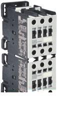
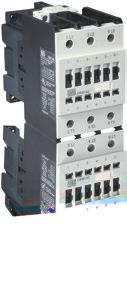
5 CWM Contactors from 9 up to 0 A (AC-3) - Accessories Overview Contactors CWM Contactors CWM Contactors CWM32/0 - Front mounting auxiliary contact block BCXMF 5 - Side mounting auxiliary contact block BCXML 6 - Mechanical interlock block BLIM 7 - Easy connection busbar 8 - Surge suppressor blocks BAM Contactors - CWM Line 5
6 CWM Contactors from 50 up to 105 A (AC-3) - Accessories Overview Contactors CWM Contactors CWM95/ Front mounting auxiliary contact block BCXMF - Side mounting auxiliary contact block BCXML 5 - Mechanical interlock block BLIM 6 - Easy connection busbar 7 - Surge suppressor blocks BAM 6 Contactors - CWM Line


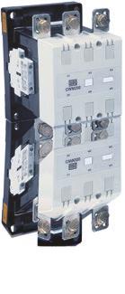
7 CWM Contactors from 112 up to 300 A (AC-3) - Accessories Overview Contactors CWM112/ Contactors CWM Contactors CWM250/300 - Side mounting auxiliary contact block BCXML 5 - Mechanical interlock BLIM Surge suppressor block BAMV 7 - Terminal cover BMP CWM Terminal cover BMP CWM Terminal cover BMP CWM TB150 terminal block for CWM TB180 terminal block for CWM TB300 terminal block for CWM Contactors - CWM Line 7

8 CWM Contactors from 00 up to 800 A (AC-3) - Accessories Overview Contactor CWM Contactors CWM Auxiliary contacts block BCXMRL CWM800 - Mechanical interlock BLIM CWM Mechanical interlock BLIM CWM Terminal cover BMP CWM Terminal cover BMP CWM Lugs BMJ CWM Lugs BMJ CWM800 8 Contactors - CWM Line
9 CWM Contactors - Selection Table Three-Pole Contactors from 9 up to 250 A (AC-3) - AC Coil 3) Rated Conv. Max. rated operational power of three-phase Auxiliary contacts Auxiliary contact blocks operational thermal motors 50/60 Hz 1) per contactor separately delivered Weight current current Reference code 220 V 380 V 00 V 0 V 500 V 660 V 3 1 I e AC-3 I th = I e to complete with 230 V 15 V 690 V BCXMF10 BCXMF01 (U e 0 V) AC-1 voltage code 2 A A kw / HP kw / HP kw / HP kw / HP kw / HP kw / HP NO NC NO NC kg 1 0 Built-in - CWM / 3 / 5 / 5.5 / 6.5 / / Built-in CWM Built-in 1 cwm CWM Built-in - CWM / 5.5 / / / / / Built-in CWM Built-in 1 CWM CWM Built-in - CWM / / / / / / Built-in CWM Built-in 1 CWM CWM CWM CWM / / / / / / CWM CWM CWM CWM CWM / / / / / / CWM CWM CWM CWM / / / / / / CWM CWM CWM / / / / 0 30 / 0 30 / CWM CWM CWM / / 0 30 / 0 37 / / / CWM CWM CWM / / 50 5 / 60 5 / 60 5 / 60 5 / CWM CWM CWM / 30 5 / / / / / CWM CWM CWM / 0 55 / / / / / CWM CWM / 0 55 / / / / / CWM / / / / / / CWM / / / / / / CWM Replace with the Appropriate Coil Voltage Code 2) AC coil - 50/60 Hz Coil voltage codes D02 D07 D13 D23 D2 D25 D33 D3 D35 D36 D39 V ac - 50/60 Hz Notes: 1) For 50/60 Hz three-phase, poles WEG standard motors. These values are only for reference and may change on the number of poles and motor design. 2) Other voltages available. 3) For selection of acessories, check page 13. Contactors - CWM Line 9
10 CWM Contactors - Selection Table Three-Pole Contactors from 0 up to 105 A (AC-3) - DC Coil )5) Rated operational current I e AC-3 (U e 0 V) Conv. thermal current I th = I e AC V 230 V Max. rated operational power of three-phase motors 50/60 Hz 1) 380 V 00 V 15 V 0 V 500 V 660 V 690 V Auxiliary contacts per contactor Auxiliary contact blocks separately delivered BCXMF10 A A kw / HP kw / HP kw / HP kw / HP kw / HP kw / HP NO NC NO NC / / / / / / / / / / 0 30 / 0 30 / / / 0 30 / 0 37 / / / / / 50 5 / 60 5 / 60 5 / 60 5 / / 30 5 / / / / / / 0 55 / / / / / 75 BCXMF01 Reference code to complete with voltage code CWM CWM CWM CWM CWM CWM CWM CWM CWM CWM CWM CWM CWM CWM CWM CWM CWM CWM Weight kg Replace with the Appropriate Coil Voltage Code 2)3) Coil voltage codes (CWM ) C3 C37 C0 C V dc Notes: 1) For 50/60 Hz three-phase, poles WEG standard motors. These values are only for reference and may change on the number of poles and motor design. 2) Other voltages available. 3) Contactors CWM0-105 with DC coils do not need surge suppressor blocks. The surge suppressor is already integrated in this coil. ) For selection of acessories, check page 13. 5) For lower currents than 0 A (AC-3) use the new line CWB Contactors - CWM Line

11 CWM Contactors - Selection Table Three-Pole Contactors from 112 up to 300 A (AC-3) - Coil with Electronic Module AC/DC Rated operational current I e AC-3 (U e 0 V) A Conv. thermal current I th = I e AC-1 A 220 V 230 V kw / HP Max. rated operational power of three-phase motors 50/60 Hz 1) 380 V 00 V 0 V 500 V 15 V kw / HP kw / HP kw / HP kw / HP 690 V kw / HP Auxiliary contacts per contactor (BCXML) 3 NO 1 2 NC Reference code to complete with voltage code / 0 55 / / / / / CWM / / / / / / CWM / / / / / / CWM / / / / / / CWM / / / / / / CWM Weight kg Replace with the Appropriate Coil Voltage Code 2) Coil voltage codes E02 E06 E07 E10 E13 E16 E21 50/60 Hz / DC 3) 2-28 V 2-50 V V V V V V Three-Pole Contactors from 00 up to 800 A (AC-3) - Coil with Electronic Module AC/DC Rated operational current I e AC-3 (U e 0 V) A Conv. thermal current I th = I e AC-1 A 220 V 230 V Max. rated operational power of three-phase motors 50/60 Hz 1) 380 V 00 V 0 V 500 V 690 V 15 V Auxiliary contacts per contactor (BCXML) kw / HP kw / HP kw / HP kw / HP kw / HP kw / HP NO NC Reference code to complete with voltage code / / / / / / CWM / / / / / / CWM / / / / / / CWM / / / / / / CWM Weight kg Replace with the Appropriate Coil Voltage Code 2) Coil voltage codes (CWM00) E36 D80 D81 D82 50/60 Hz / DC 3) V ac / V dc /60 Hz 3) V V V Coil voltage codes (CWM500/630/800) E35 E39 D80 D81 D82 50/60 Hz / DC 3) V ac / V dc V ac / V dc /60 Hz 3) V V V Notes: 1) For 50/60 Hz three-phase, poles WEG standard motors. These values are only for reference and may change on the number of poles and motor design. 2) Other voltages available. 3) Surge suppressor is already integrated. Contactors - CWM Line 11

12 CWM Contactors - Selection Table Four-Pole Contactors from 25 to 32 A (AC-1) I e = I th (U e 690 V) θ 55 C AC-1 A NO Number of poles Reference code to complete with voltage code 2 2 CWM CWM CWM CWM CWM CWM NC Weight kg Replace with the Appropriate Coil Voltage Code 1) AC coil - 50/60 Hz Applicable for CWC07 CWC025 models Coil voltage codes D02 D07 D13 D23 D2 D25 D33 D3 D35 D36 D39 V ac - 50/60 Hz Four-Pole Contactors from 20 up to 800 A AC-1 - Coil with Electronic Module AC/DC Conv. thermal current I th (55ºC) A AC-1 current A 220 V 20 V 380 V 00 V AC-1 power 500 V 550 V 690 V Auxiliary contacts per contactor (BCXML) kw kw kw kw NO NC Reference code to complete with voltage code CWM CWM CWM CWM Replace with the Appropriate Coil Voltage Code 2) Coil voltage codes (CWM00) E36 D80 D81 D82 50/60 Hz / DC 3) V ac / V dc /60 Hz 3) V V V Weight kg Coil voltage codes (CWM500/630/800) E35 E39 D80 D81 D82 50/60 Hz / DC 3) V ac / V dc V ac / V dc /60 Hz 3) V V V 12 Contactors - CWM Line
13 CWM Contactors - Accessories Auxiliary Contact Blocks g Terminal markings to EN and EN g Positive driven contacts in accordance with IEC resp. IEC Illustrative picture For use with Max. number of contacts/ contactor Auxiliary contacts NO NC Reference code Weight kg 1 0 BCXMF BCXMF01 1 1) 0 BCXMFA10 CWM / CWM ) BCXMFR / CWM ) 0 BCXMF10AU 8 / CWM ) BCXMF01AU 8 / CWM BCXML BCXML11 CWM BCXMRL20 3) 1 1 BCXMRL11 3) CWM / CWM BCXML11 CWM800 BCXMRL11 CWM800 3) 0.05 Mechanical Interlock for Contactors 5) Illustrative picture For use with Reference code Weight kg CWM9...CWM105-3 or -pole BLIM9-105 BLIM.02 ) CWM112...CWM300-3-pole BLIM CWM00-3 or -pole BLIM CWM CWM pole BLIM CWM CWM pole BLIM CWM800-P 16.0 Notes: 1) Early-make contact. 2) Late-break contact. 3) For combination of more than 2 side-mounted auxiliary contacts. ) This accessory allows mechanical and electrical interlock. 5) Can only be used with 2 contactors of the same frame. 6) Auxiliary contact block for low current levels (1 ma / 17 V). Contactors - CWM Line 13
14 CWM Contactors - Accessories Surge Suppressors g Connect directly to coil terminals A1 - A2 Illustrative picture For use with Voltage Circuit diagram Reference code 2-8 V 50/60 Hz BAMRC D53 CWM V 50/60 Hz BAMRC5 D V 50/60 Hz BAMRC6 D V 50/60 Hz BAMRC7 D53 CWM V 50/60 Hz BAMRC8 D V 50/60 Hz BAMRC9 D63 CWM V 50/60 Hz BAMRC13 D V 50/60 Hz BAMRC1 D V 50/60 Hz BAMV1 D68 CWM V 50/60 Hz BAMV2 D V 50/60 Hz BAMV3 D68 CWM V 50/60 Hz BAMV D73 Weight kg 0.01 Terminal Cover g Protection against touching in accordance with relating installation rules Illustrative picture For use with Description Reference code Terminal Blocks 2) Illustrative picture For use with Flexible cable Tightening torque Description Reference code CWM112/150 CWM180 CWM250/300 CWM112/ mm² 3...2/0 AWG mm² 1/ kcmil AWG mm² 1/ kcmil AWG 1 N.m Weight kg BMP CWM CWM180 1 kit with 2 parts 1) BMP CWM CWM250/300 BMP CWM CWM112/150 BMP1 CWM CWM180 1 kit with 1 part 1) BMP1 CWM CWM250/300 BMP1 CWM CWM00 (3-pole) BMP CWM CWM (3-pole) BMP CWM kit with 2 parts 1) CWM00 (-pole) BMP CWM00-P 0.16 CWM (-pole) BMP CWM800-P 0.37 Weight kg TB N.m 1 unit (3-pole) TB N.m TB Lug Terminals Illustrative picture For use with Description Reference code Weight kg CWM00 1 kit with 3 pieces BMJ CWM CWM kit with 3 pieces BMJ CWM Notes: 1) Every part is a 3-phase protector. 2) For IP20 protection degree on front. 1 Contactors - CWM Line


15 CWM Contactors - Accessories Reversing Wiring Kits 1) Illustrative picture Rated operational current Ie AC - 3 (U e 0 V) A Maximum rated operational power of three-phase motors 50/60 Hz Contactors Reference V V V code kw / HP kw / HP kw / HP K1 = K / 3 / / 7.5 CWM / 5.5 / / 10 CWM / / / 15 CWM / / / 15 CWM25 EC-RC / / / 25 CWM / / / 30 CWM / / / 0 CWM / / 0 37 / 50 CWM / 30 5 / 60 5 / 60 CWM80 Weight kg EC-R EC-RC-18.5 EC-RC A1 A2 A A1 A2 Star-Delta Wiring Kits 1) Illustrative picture Rated operational current Ie AC - 3 (U e 0 V) A Maximum rated operational power of three-phase motors 50/60 Hz Contactors Reference V V V code kw / HP Electrical diagram kw / HP kw / HP K1 = K2 K / / / 25 CWM18 CWM / / / 25 CWM18 CWM / / / 30 CWM25 CWM / / / 30 CWM25 CWM18 Weight kg EC-SD EC-SD / / / 0 CWM32 CWM18 EC-SD / / 0 37 / 50 CWM0 CWM25 EC-SD / / 50 5 / 60 CWM50 CWM25 EC-SD / 30 5 / / 75 CWM50 CWM / 0 55 / / 75 CWM65 CWM0 EC-SD / / / 100 CWM80 CWM50 EC-SD / / / 125 CWM95 CWM / / / 150 CWM105 CWM65 EC-SD A A A1 A A2 2 6 A2 Electrical diagram 3-Pole Jumper (k3) for Star-Delta Starters Illustrative picture For use with Description Note: 1) Contactors and mechanical interlock are sold separately. CWM Reference code Weight kg SBCM CWM25 3-pole jumper to connect in parallel L1-L2-L3 SBCM CWM32/0 k3 contactor terminals in a star-delta starter SBCM CWM50/65 SBCM Contactors - CWM Line 15
16 CWM Contactors - Reversing Starters Individual Components for Reversing Starters V kw / HP Maximum rated operational power of three-phase motors 50/60 Hz V kw / HP 500 V kw / HP Individual components for reversing starters Contactor Contactor Spare auxiliary contacts V K1 K2 kw / HP Type Type K1 K2 2.2 / 3 / 5.5 / / 7.5 CWM9-11 CWM / 5.5 / / / 10 CWM12-11 CWM / / / / 15 CWM18-11 CWM / / / / 15 CWM25-11 CWM / / / / 25 CWM32-11 CWM / / / / 30 CWM0-11 CWM / / / 0 30 / 0 CWM50-11 CWM / / 0 37 / / 50 CWM65-11 CWM / 30 5 / 60 5 / 60 5 / 60 CWM80-11 CWM / / / / 75 CWM95-11 CWM / 0 55 / / / 75 CWM CWM / 0 55 / / / 100 CWM CWM NO/1NC 1NO/1NC 5 / / / / 150 CWM CWM NO/1NC 1NO/1NC 55 / / / / 150 CWM CWM NO/1NC 1NO/1NC 75 / / / / 220 CWM CWM NO/1NC 1NO/1NC 90 / / / / 270 CWM CWM NO/1NC 1NO/1NC Mechanical interlock BLIM9-105 BLIM Wiring kit EC-SD... - Reversing starters 16 Contactors - CWM Line
17 CWM Contactors - Star-Delta Starters Individual Components for Star-Delta Starters V kw / HP Maximum rated operational power of three-phase motors 50/60 Hz V kw / HP 500 V kw / HP Main contactor K1 Delta contactor K2 Individual components for star-delta starters Star contactor K3 Spare auxiliary contacts V Timer kw / HP Type Type Type K1 K2 K3 5.5 / / / / 25 CWM BCXMF10 CWM18-11 CWM9-11 RTW-ET / / / / 25 CWM BCXMF10 CWM18-11 CWM / / / / 30 CWM x BCXMF10 CWM25-11 CWM / / / / 30 CWM x BCXMF10 CWM25-11 CWM / / 0 37 / / 50 CWM x BCXMF10 CWM0-11 CWM / / / 50 5 / 60 CWM x BCXMF10 CWM50-11 CWM / 30 5 / 60 5 / / 75 CWM x BCXMF10 CWM50-11 CWM / 0 55 / / / 75 CWM x BCXMF10 CWM65-11 CWM / / / / 125 CWM x BCXMF10 CWM95-11 CWM / / / / 150 CWM x BCXMF10 CWM CWM / / / / 175 CWM CWM CWM NC 1NO/NC - 75 / / / / 175 CWM CWM CWM NC 1NO/NC - 90 / / / / 300 CWM CWM CWM NC 1NO/NC / / / CWM CWM CWM NC 1NO/NC 1NO/NC Wiring kit EC-SD... Star-Delta Starter K1 K1 K3 K2 Star-Delta Starters U1 V1 W1 V2 U2 W2 K3 K2 A: 0.58 x Ir, motor protection at star and delta position B: 1 x Ir, only partial motor protecton at star position C: 0.58 x Ir, motor not protected at star position Contactors - CWM Line 17
18 CWM Contactors - Spare Parts Individual Spare Coils Illustrative picture Description For use with AC coil DC coil Dual-voltage coils AC/DC (contactors with electronic module) Reference code to complete with voltage code Weight kg CWM BCA CWM BCA CWM BCA CWM112 BCA CWM180 BCA CWM250 BCA CWM0 BECC CWM BECC CWM BCE CWM180 BCE CWM BCE CWM00 CWM BCE00 BCE Electronic Module Illustrative picture Control type For use with Reference code Weight kg AC/DC CWM ME-300 2) 0.10 Replace with the Appropriate Coil Voltage Code 1) Contactors CWM Coil voltage codes (CWM ) D02 D07 D13 D2 D25 D3 D35 50/60 Hz 2 V 8 V 110 V 230 V 20 V 00 V 15 V Coil voltage codes (CWM ) C3 C37 C0 C V dc 2-28 V 2-50 V V V Coil voltage codes (CWM ) E02 E06 E07 E10 E13 E16 E21 50/60 Hz / DC 3) 2-28 V 2-50 V V V V V V Contactors CWM Coil voltage codes (CWM00) E36 D80 D81 D82 50/60 Hz / DC 3) V ac / V dc /60 Hz 3) V V V Coil voltage codes (CWM ) E35 E39 D80 D81 D82 50/60 Hz / DC 3) V ac / V dc V ac / V dc /60 Hz 3) V V V Notes: 1) Other voltages on request. 2) The coil voltage code must be the same of BCE coil voltage code selected. 3) Surge suppressor is already integrated. 18 Contactors - CWM Line
19 CWM Contactors - Technical Data General Data Reference code CWM9 CWM12 CWM18 CWM25 CWM32 CWM0 CWM50 CWM65 CWM80 CWM95 CWM105 CWM112 CWM150 CWM180 CWM250 CWM300 Standards IEC 6097 / UL 508 Rated insulation voltage U i IEC 6097 UL / CSA Rated impuse withstand voltage U imp 6 kv 8 kv Rated operational frequency Hz Degree of protection Protection against direct contact from the front when operated by a perpendicular test finger (IEC 536) Main circuits IP20 IP10 IP00 Control circuits and auxiliary contacts IP20 Ambient temperature Operating temperature Storage temperature -25 o C to +55 o C -55 o C to +80 o C Altitude Normal values 90% I e / 80% U e 80% I e / 75% U e Up to 3,000 m 3,000 to,000 m,000 to 5,000 m Overvoltage category / Pollution degree III / 3 Climatic proofing Acc. IEC Pole numbers of main circuits 3 Rated operation voltage U e 690 V 1,000 V Mechanical lifespan Ops x Electrical lifespan (AC - 3) Ops x Mounting Screw or 35 mm DIN Rail Screw 1,000 V 600 V Control Circuit Reference code CWM9 CWM12 CWM18 CWM25 CWM32 CWM0 CWM50 CWM65 CWM80 CWM95 CWM105 CWM112 CWM150 CWM180 CWM250 CWM300 Rated insulation IEC 1,000 V voltage U i UL, CSA 600 V Rated voltages (standard coil) Us 50/60 Hz V V Rated voltages (electronic module) Us 50/60 Hz V Rated voltages Us dc V V Closing/Opening (AC) ms / / / / Operation time 1) Closing/Opening (DC) ms / / / Power consumption of the AC coil 50/60 Hz 1) Pick-up (VA) cos ϕ Sealing (VA) cos ϕ Coil operation limits 50/60 Hz 1) x U s x U s Pick-up Bifrequency coils 1) Sealing Power consumption of the coil - DC coils Pick-up (W) Sealing (W) Number of terminals AC coil 3 2 DC coil Note: 1) Values applicable for contactors CWM with electronic module. For contactors with standard coil only on request. Contactors - CWM Line 19
20 CWM Contactors - Technical Data Main Contacts Reference code CWM9 CWM12 CWM18 CWM25 CWM32 CWM0 CWM50 CWM65 CWM80 CWM95 CWM105 CWM112 CWM150 CWM180 CWM250 CWM300 Rated AC-3 (U e 0 V) (A) operational AC- (U e 0 V) (A) current I e AC-1 (θ 55 C, U e 690 V) (A) Rated IEC/EN , VDE 0660 (V) 690 1,000 operational voltage U e UL, CSA (V) 600 Rated thermal current I th (θ 55 C) (A) Making capacity - IEC/EN 6097 (A) ,000 1,000 1,000 1,280 1,280 1,30 1,820 2,100 2,600 3,000 Breaking (U e 00 V) (A) ,050 1,050 1,290 1,350 1,00 2,000 - capacity (U e =500 V) (A) ,050 1,050 1,290 1,350 1,00 2,000 - IEC/EN 6097 (U e =690 V) (A) Short-time 1 sec (A) ,010 1,265 1,580 2,530 2,530 3,300 3,300 3,165 3,763,69,27 - current 5 sec (A) ,130 1,130 1,85 1,85 1,820 2,16 2,673 2,56 - No current 10 sec (A) ,050 1,050 1,30 1,700 2,100 2,000 - flowing during 30 sec (A) ,212 1,155 recovery time 10 min. and 1 min (A) θ 0 C) 3 min (A) V - UL/CSA (ka) against shortcircuits with Coordination type 1 (A) fuses(gl/gg) Coordination type 2 (A) Impedance per pole (mω) Power dissipation AC-1 (W) per pole AC-3 (W) Utilization category AC-3 U Rated e 0 V (A) operational U e 500 V (A) current I e U e 690 V (A) (θ 55 C) U e 1,000 V (A) Not available / 230 V (kw) (HP) / V (kw) (HP) (kw) / 15 V Rated (HP) operational (kw) power 0 V (HP) V (kw) (HP) / 690 V (kw) (HP) Percentage of 600 ops./h (%) the maximum operational 1,200 ops./h (%) current at 3,000 ops./h (%) Utilization category AC- Rated operational current Ie AC- (U e 690 V) (A) / 230 V (kw) (HP) / 00 V (kw) (HP) (kw) V Rated (HP) operational (kw) power 0 V (HP) V (kw) (cv) / 690 V (kw) (cv) Contactors - CWM Line
21 CWM Contactors - Technical Data Main Contacts Reference code CWM9 CWM12 CWM18 CWM25 CWM32 CWM0 CWM50 CWM65 CWM80 CWM95 CWM105 CWM112 CWM150 CWM180 CWM300 Utilization category AC-1 3P (NO) or P (NO) 3P (NO) 3P (NO) Rated thermal current I th (θ 55 C) (A) θ 55 C (A) Max. operational current at ambient temperature of (up to 690 V) θ 70 C (A) θ 75 C (A) / 230 V (kw) / 00 V (kw) Max. operational power 15 / 0 V (kw) θ 55 C (Three-phase resistors) 500 V (kw) / 600 V (kw) / 690 V (kw) Cable size (mm²) x poles in parallel I e x 1.7 Current values for connection of 3 poles in parallel I e x 2. poles in parallel I e x ops./h (%) Percentage of the maximum operational current at 1,200 ops./h (%) ,000 ops./h (%) P (NO/NC) P (2NO+2NC) 2P (NO/NC) Max. operational power θ 55 C (Resistive loads) 220 / 230 V (kw) / 00 V (kw) / 0 V (kw) V (kw) / 690 V (kw) UL Power Reference code CWM9 CWM12 CWM18 CWM25 CWM32 CWM0 CWM50 CWM65 CWM80 CWM95 CWM105 CWM112 CWM150 CWM180 CWM250 CWM300 General purpose current (600 V) (A) / 120 V (HP) phase 220 / 20 V (HP) V (HP) / 20 V (HP) phase 0 / 80 V (HP) / 600 V (HP) Contactors - CWM Line 21
22 CWM Contactors - Technical Data General Data and Main Contacts Reference code CWM00 CWM500 CWM630 CWM800 Standards IEC 6097 / UL 508 Rated insulation voltage U i IEC 6097 UL Rated impuse withstand voltage U imp Rated operational frequency Degree of protection Main circuits Control circuits and auxiliary contacts Ambient temperature Operating temperature Storage temperature Altitude Normal values 90% I e / 80% U e 80% I e / 75% U e 1,000 V 600 V 6 kv Hz IP00 IP20-25 o C to + 55 o C -55 o C to + 80 o C Up to 3,000 m 3,000 to,000 m,000 to 5,000 m Overvoltage category / Pollution degree III / 3 Climatic proofing Acc. to IEC Pole numbers of main circuits 3 Rated operation voltage U e 690 V Conv. thermal current I th at < 55 o C rated operational current Ie/AC-1 (A) Rated operational current I e AC- (U e 0 V) (A) AC-3 utilization category Rated operational power V (kw) V (kw) 0 V (kw) 500 V (kw) 690 V (kw) Short-circuit rating max. fuse gl-gg (A) ,000 Max. electrical operational per hour AC-1 Ops/h AC-3 Ops/h 1,200 1,200 1,200 1,200 AC- Ops/h No load Ops/h 1,200 1,200 1,200 1,200 Mechanical lifespan Ops x Electrical lifespan (AC-3) Ops x UL Power Ratings Reference code CWM00 CWM500 CWM630 CWM800 General purpose current (600 V) (A) phase Control Circuit Reference code (3 pole and pole contactors) CWM00 CWM500 CWM630 CWM800 Coil operation limit x U s Pick-up (xus) Drop-out (xus) Coil consumption 200 V (HP) / 20 V (HP) / 80 V (HP) / 600 V (HP) Closing (VA) 571 1,000 Closed (VA) 1 29 Dissipation (W) Number of terminals Contactors - CWM Line
23 CWM Contactors - Technical Data Terminal Capacity and Tightening Torque - Power Terminals Reference code CWM9 / CWM12 / CWM18 CWM25 Screw type Power terminal capacity 1) mm² Finely stranded with end sleeve 1x x M3.5x 9 Flat / Phillips Stranded and finely stranded without end sleeve 1x x x Solid 1x x x Finely stranded with end sleeve 1x x x Mx 12 Flat / Phillips Stranded and finely stranded without end sleeve 1x x AWG (UL) Tightening torque (N.m) Tightening torque (lb.in) (UL) Solid 1x x x Note: this information is also valid for built-in auxiliary terminals for CWM9 to CWM18. Reference code CWM32 / CWM0 CWM50 / CWM65 / CWM80 CWM95 / CWM105 Screw type Power terminal capacity One conductor on bottom Finely stranded with end sleeve Mx 16.5 Flat / Phillips Stranded and finely stranded without end sleeve Solid Finely stranded with end sleeve M8 Allen mm Stranded and finely stranded without end sleeve Solid Finely stranded with end sleeve M10 Allen mm Stranded and finely stranded without end sleeve Solid mm² AWG (UL) / /0 One conductor on top mm² AWG (UL) / /0 Two conductors at the same time - bottom conductor mm² AWG (UL) / /0 Two conductors at the same time - top conductor mm² AWG (UL) / /0 Tightening torque (N.m) Tightening torque (lb.in) (UL) Screw type Main terminal capacity mm² AWG (UL) Reference code CWM112 / CWM150 M6 Hexagon head Solid and stranded Busbars with end sleeve 2x x 2...3/0 2 x (15 x 3) - CWM180 M8 Hexagon head Solid and stranded Busbars with end sleeve 2x x 1/ x (20 x 3) - CWM250 / CWM300 M10 Hexagon head Solid and stranded Busbars with end sleeve 2x x 1/ x (30 x 5) CWM00 M12 Hexagon head Solid and stranded Busbars with end sleeve 2x x x (30x5) CWM500 / CWM630 M16 Hexagon head Solid and stranded Busbars with end sleeve 2x x Tightening torque (N.m) x (50x5) - CWM800 M16 Hexagon head Solid and stranded Busbars with end sleeve 2x x x (60x5) - Contactors - CWM Line 23
24 CWM Contactors - Technical Data Terminal Capacity and Tightening Torque - Coil Terminals Reference code CWM CWM Screw type Coil terminal mm² AWG (UL) Finely stranded with end sleeve 1x x x x x x M3.5x 10 Flat / Phillips Stranded and finely stranded without end sleeve 1x x x x Solid 1x x x x x x Finely stranded with end sleeve 1x x x x x x M3.5x 10 Flat / Phillips Stranded and finely stranded without end sleeve 1x x x x Tightening torque (N.m) Tightening torque (lb.in) (UL) Solid 1x x x x x x Reference code CWM00...CWM800 Screw type M Flat / Phillips Coil terminal Finely stranded with end sleeve Stranded and finely stranded without end sleeve Solid mm² 1x or 2x AWG (UL) Tightening torque (N.m) Tightening torque (lb.in) (UL) Terminal Capacity and Tightening Torque - Auxiliary Contact Blocks Reference code BCXMF BCXML Screw type M3.5x9 Fenda / Philips Auxiliary contact block Finely stranded with end sleeve Stranded and finely stranded without end sleeve Solid mm² 1x x x x AWG (UL) Tightening torque (N.m) Tightening torque (lb.in) (UL) 10 1x x Contactors - CWM Line
25 CWM Contactors - Technical Data Auxiliary Contacts Reference code Built-in auxiliary contacts of contactors Auxiliary contact blocks CWM9 CWM12 CWM18 BCXMF... BCXML... BCXMF_AU Rated insulation voltage U i IEC/EN UL/CSA (V) (V) Rated operational voltage U e (V) Conv. thermal current I th (A) , , Rated operational current I e AC-15 UL/CSA DC-13 UL/CSA V V 15 V 500 V 2 V 8 V 110 V 220 V (A) (A) (A) (A) (A) (A) (A) (A) A P A Q A Q600 Making capacity I m AC-15/AC-11 AC-13/DC-11 U e 00 V 50/60 Hz U e 220 V dc (A) (A) Breaking capacity I c AC-15/AC-11 AC-13/DC-11 U e 00 V 50/60 Hz U e 220 V dc (A) (A) Short-circuit protection max. fuse gl/gg (A) Control circuit reliability l e min = 5 ma U e min = 17 V Electrical lifespan Ops 10 6 Mechanical lifespan Ops 10 x l e min = 1 ma U e min = 17 V Reference code BCXML11 CWM800 / BCXMRL11 CWM800 Conv. thermal current I th (A) 16 Rated operational current I e AC category (A600) DC category (P600) 110 V (A) 220 V (A) 0 V (A) 600 V (A) 2 V (A) 8 V (A) 110 V (A) 220 V (A) AC DC Mechanical lifespan Ops x AC Electrical lifespan Operations x 10 6 AC DC-13 / DC Max. electrical operational per hour 1,800 AC DC Contactors - CWM Line 25
26 CWM Contactors - Technical Data Contactors for Lighting Circuits Maximum number of lamps per phase at 220 V Lamp type W A µf CWM9 CWM12 CWM18 CWM25 CWM32 CWM0 CWM50 CWM65 CWM80 CWM95 CWM105 Incandescent Fluorescent Single arrangement Without compensation Fluorescent Single arrangement With compensation High pressure Mercury vapour Without compensation High pressure Mercury vapour With compensation High pressure Sodium vapour Without compensation High pressure Sodium vapour With compensation Metal iodide Without compensation Metal iodide With compensation , , AC-5b¹ ) (A) , , , , , , , , Note: indicative values - It s highly recommended to take into consideration the values of making capacity and rated AC-1 current when dimensioning the contactor for AC-5b utilization category (AC-5b - Switching of incandescent lamps). 26 Contactors - CWM Line
27 CWM Contactors - Technical Data Contactors for Lighting Circuits Maximum number of lamps per phase at 220 V Lamp type W A µf CWM112 CWM150 CWM180 CWM250 CWM300 Incandescent Fluorescent Single arrangement Without compensation Fluorescent Single arrangement With compensation High pressure Mercury vapour Without compensation High pressure Mercury vapour With compensation High pressure Sodium vapour Without compensation High pressure Sodium vapour With compensation Metal iodide Without compensation Metal iodide With compensation , , AC-5b¹ ) (A) ,522 1, , , , , , , , , , Note: indicative values - It s highly recommended to take into consideration the values of making capacity and rated AC-1 current when dimensioning the contactor for AC-5b utilization category (AC-5b - Switching of incandescent lamps). Contactors - CWM Line 27
28 CWM Contactors - Technical Data DC - Utilization Category Utilization Category DC-1 (L/R 1ms) Reference code CWM9 CWM12 CWM18 CWM25 CWM32 CWM0 CWM50 CWM65 CWM80 CWM95 CWM105 U e Poles in series Maximum operational current I e (A) V V V V V V V Utilization Category DC-3 (L/R 2.5ms) Reference code CWM9 CWM12 CWM18 CWM25 CWM32 CWM0 CWM50 CWM65 CWM80 CWM95 CWM105 U e Poles in series Maximum operational current Ie (A) V V V V V V V Contactors - CWM Line
29 CWM Contactors - Technical Data DC - Utilization Category Utilization Category DC-5 (L/R 15ms) Reference code CWM9 CWM12 CWM18 CWM25 CWM32 CWM0 CWM50 CWM65 CWM80 CWM95 CWM105 U e Poles in series Maximum operational current Ie (A) V V V V V V V Utilization Category DC-1 (L/R 1ms) Reference code CWM112 CWM150 CWM180 CWM250 CWM300 U e Poles in series Maximum operational current I e (A) V V V V Contactors - CWM Line 29
30 CWM Contactors - Technical Data DC - Utilization Category Utilization Category DC-3 / DC-5 (L/R 15ms) Reference code CWM112 CWM150 CWM180 CWM250 CWM300 U e Poles in series Maximum operational current I e (A) V V V V Utilization Category DC-1 (L/R 1ms) Reference code CWM00 CWM500 CWM630 CWM800 U e Poles in series Maximum operational current I e (A) 2 V V V V Utilization Category DC-2 / DC- (L/R 15ms) Utilisation category CWM00 CWM500 CWM630 CWM800 U e Poles in series Maximum operational current I e (A) 2 V V V V Poles in Series 3 Poles in Series Load Load Load 2 Poles in Series Poles in Series Load Load Load Load 30 Contactors - CWM Line
31 CWM Contactors - Technical Data Terminal Markings to EN Diagram Without auxiliary contact blocks Distinctive number and version of combination NO NC Reference code Additional auxiliary contact blocks 10E 1 0 CWM9-10 CWM12-10 CWM E 0 1 CWM9-01 CWM12-01 CWM Front mounting auxiliary contact blocks BCXMF10 or BCXMF01 11E 1 1 CWM9-10 CWM12-10 CWM BCXMF01 21E 2 1 CWM9-10 CWM12-10 CWM BXCMF10 + BCXMF01 12E 1 2 CWM9-10 CWM12-10 CWM BXCMF01 31E 3 1 CWM9-10 CWM12-10 CWM BXCMF10 + BCXMF01 1E 1 CWM9-10 CWM12-10 CWM BXCMF10 + BCXMF01 Contactors - CWM Line 31
32 CWM Contactors - Technical Data Terminal Markings to EN Diagram Front mounting auxiliary contact blocks BCXMF10 or BCXMF01 Distinctive number and version of combination NO NC Reference code Additional auxiliary contact blocks 22E 2 2 CWM9-10 CWM12-10 CWM BXCMF01 + BCXMF10 32E 3 2 CWM9-10 CWM12-10 CWM BXCMF BCXMF10 13E 1 3 CWM9-10 CWM12-10 CWM BXCMF01 23E 2 3 CWM9-10 CWM12-10 CWM BXCMF01 + BCXMF10 Side mounting auxiliary contact blocks each with two contacts 11E 1 1 CWM25-00 to CWM BCXML11 31E 3 1 CWM25-00 to CWM BCXML11 + BCXML20 22E 2 2 CWM25-00 to CWM BCXML BCXMRL11 Without auxiliary contact blocks CWM25-00 to CWM Front mounting auxiliary contact blocks BCXMF10 or BCXMF01 10E 1 0 CWM25-00 to CWM BCXMF10 01E 0 1 CWM25-00 to CWM BCXMF01 32 Contactors - CWM Line
33 CWM Contactors - Technical Data Terminal Markings to EN Diagram Front mounting auxiliary contact blocks BCXMF10 or BCXMF01 Distinctive number and version of combination NO NC Reference code Additional auxiliary contact blocks 11E 1 1 CWM25-00 to CWM BCXMF10 + BCXMF01 21E 2 1 CWM25-00 to CWM BCXMF10 + BCXMF01 12E 1 2 CWM25-00 to CWM BCXMF BXCMF01 31E 3 1 CWM25-00 to CWM BXCMF10 + BCXMF01 1E 1 CWM50-00 to CWM BXCMF10 + BCXMF01 22E 2 2 CWM25-00 to CWM BXCMF BCXMF10 32E 3 2 CWM50-00 to CWM BXCMF BCXMF10 13E 1 3 CWM25-00 to CWM BCXMF BXCMF01 23E 2 3 CWM50-00 to CWM BXCMF BCXMF10 Contactors without auxiliary contact blocks + Side mounting auxiliary contact blocks each with two contacts CWM112 to CWM BCXML11 A A CWM112 to CWM BCXML BCXMRL11 Contactors - CWM Line 33
34 CWM Contactors - Technical Data Terminal Markings to EN Diagram pole contactors A1 A A1 A2 1 2 R1 R2 R3 R 3 Configuration Power contacts NO NC Reference code CWM CWM CWM CWM CWM CWM Diagram Front mounting auxiliary contact blocks BCXMF10 or BCXMF01 Configuration NO Auxiliary contacts NC Reference code BCXMF BCXMF BCXMFA BCXMFR01 Diagram Side mounting auxiliary contact blocks each with two contacts Configuration NO Auxiliary contacts NC Reference code BCXML BCXML BCXMRL BCXMRL11 11 BCXML11 CWM BCXMRL11 CWM800 Electrical and mechanical interlock for contactors BLIM.02 3 Contactors - CWM Line
35 CWM Contactors - Technical Data Electrical Lifespan AC-3 (U e 0 V ac) CWM9 CWM12 CWM18 CWM25 CWM32 CWM0 CWM50 CWM65 CWM80 CWM95 CWM105 CWM112 CWM150 CWM180 CWM250 CWM Number of operations (10 6 ) ,000 Rated operational current I e (A) Number of operations (10 6 ) 0.1 CWM00 CWM500 CWM630 CWM800 Rated operational current I e (A) 1,000 Contactors - CWM Line 35
36 CWM Contactors - Technical Data Electrical Lifespan AC- (U e 0 V ac) CWM9 CWM12 CWM18 CWM25 Number of operations (10 6 ) CWM32 CWM0 CWM50 CWM65 CWM80 CWM95 CWM Breaking current I c (A) 1,000 CWM112 CWM150 CWM180 Number of operations (10 6 ) CWM250 CWM ,000 Breaking current I c (A) 36 Contactors - CWM Line
37 CWM Contactors - Technical Data Electrical Lifespan AC- (U e 0 V ac) 1.0, Number of operations (10 5 ) 0.1, CWM00 CWM500 CWM , CWM800 1,000 Breaking current I c (A) - AC- AC-1 (U e 690 V ac) 10 CWM9 CWM12 CWM18 CWM25 CWM32 CWM0 CWM50 CWM65 CWM80 CWM95 CWM105 Number of operations (10 5 ) , ,000 Breaking current I c (A) - AC- Contactors - CWM Line 37
38 CWM Contactors - Technical Data Electrical Lifespan AC-1 (U e 690 V ac) Number of operations (x10 6 ) CWM112 CWM150 CWM180 CWM250 CWM ,000 Breaking current I c (A) CWM00 Number of operations (x10 6 ) 0.1 CWM500 CWM630 CWM800 1,000 Breaking current I c (A) 38 Contactors - CWM Line
39 CWM Contactors - Dimensions (mm) CWM9, CWM12 and CWM DIN RAIL 35 mm BCXMF BCXML BCXML CWM A , DIN RAIL 35 mm BCXMF CWM32 and CWM0 BCXML BCXML Coil AC DC A = 98 A = A DIN RAIL 35 mm BCXMF BCXML CWM50, CWM65 and CWM A 29 Coil AC DC A = 116 A = DIN RAIL 35 mm BCXML BCXMF BCXML BCXML Contactors - CWM Line 39
40 CWM Contactors - Dimensions (mm) CWM95 and CWM Coil AC DC A = 126 A = 126 A DIN RAIL 35 mm BCXMF CWM112 and CWM ME-300 (eletronic module) 7 BCXMRL CWM150 BCXML CWM ME-300 (eletronic module) BCXMRL BCXML 162, CWM Ø9 BCXML 0 Contactors - CWM Line
41 CWM Contactors - Dimensions (mm) CWM250 and CWM ME-300 (electronic module) A C A B Models A B C D CWM CWM CWM CWM BLIM A C A Models A B C D CWM CWM CWM B BCXMRL 200 BCXML Ø11 BLIM9-105 and BLIM D Contactors - CWM Line 1
42 CWM Contactors - Dimensions (mm) BMP CWM BMP CWM150 + CWM112/150 BMP CWM180 + CWM180 BMP CWM300 + CWM250/300 A B C D E F TB... + CWM A TB150 + CWM112/150 TB180 + CWM180 TB300 + CWM250/300 A B B Mounting Position CWM CWM Contactors - CWM Line
43 225 CWM Contactors - Dimensions (mm) CWM00-3-Pole , , Ø 9 Ø ,3 207, , R,5 50 1,5 Ø 1 Ø CWM00 - -Pole , , 8xØ9 8xØ R Ø1 Ø Contactors - CWM Line 3
44 Ø CWM Contactors - Dimensions (mm) CWM500, CWM630 and CWM800-3-Pole , , Ø 15,9 Ø15.9 Ø 17 0 CWM500, CWM630 and CWM Pole 35 0, Ø R7.9 R7,9 Ø17 19, , , , Contactors - CWM Line
45 CWM Contactors - Dimensions (mm) BLIM CWM00 B C E D BLIM BLIN CWM00 E A G BLIM CWM800 Ø C C B B D F A E BLIM CWM00 + CWM00 BLIM CWM800 + CWM pole -pole 3-pole -pole A B C D E 0 85 F 0 85 G A B C D 0 0 E F G Contactors - CWM Line 5
46 CWM Contactors - Dimensions (mm) BMP CWM A C ED BMP CWM00 + CWM00 BMP CWM800 + CWM pole -pole 3-pole -pole A B B C D E E E BMJ CWM B A D F BMJ CWM00 + CWM00 BMJ CWM800 + CWM E E H H A B C D E F G G C Mounting Position CWM Contactors - CWM Line 50


47 Global presence is essential, as much as understanding your needs. Global Presence With more than employees worldwide, WEG is one of the largest electric motors, electronic equipments and systems manufacturers. We are constantly expanding our portfolio of products and services with expertise and market knowledge. We create integrated and customized solutions ranging from innovative products to complete after-sales service. WEG s know-how guarantees our Contactors - CWM Line is the right choice for your application and business, assuring safety, efficiency and reliability. Availability is to have a global support network Partnership is to create solutions that suits your needs Competitive edge is to unite technology and inovation Know More High performance and reliable products to improve your production process. Excelence is to provide a whole solution in industrial automation that improves our customers productivity. Visit: youtube.com/wegvideos Contactors - CWM Line 7
Controls. CONTACTORS CWB Line (up to 40A)
") Controls CONTACTORS CWB Line (up to 40A) 0800 367 934 Contactors CWB Line (up to 40A) CONTACTORS CWB Line (up to 40A) Summary New WEG CWB Contactors 4 The Technology Within 6 Energy Savings 7 Easy Panel
Controls CONTACTORS CWB Line (up to 40A) 0800 367 934 Contactors CWB Line (up to 40A) CONTACTORS CWB Line (up to 40A) Summary New WEG CWB Contactors 4 The Technology Within 6 Energy Savings 7 Easy Panel
CWM_N NEMA Rated Contactors
 Motors Automation Energy Transmission & Distribution Coatings CWM_N NEMA contactors have been a mainstay in the industrial marketplace in the US for decades. NEMA contactors were known for being robust
CI-TI Contactors and motor starters Types CI 61 - CI 98
 Data sheet CI-TI Contactors and motor starters s CI 6 - CI 98 Contactors CI 6, CI 7, CI 86 and CI 98 switch powers of up to 0 kw, 7 kw, 45 kw and 55 kw respectively under 80 V - loads. Accessories include
Approved Standards. Motor Contactor. Main contactor. Accessoires. 21 Motor Contactor J7KN
 Motor Contactor Main contactor AC & DC operated Integrated auxiliary contacts Screw fixing and snap fitting (35 mm DIN rail) up to 45 kw Range from 4 to 110 kw (AC 3, 380/415V) Finger proof ( VBG 4) Accessoires
AF40... AF96 3-pole contactors Technical data
 Main pole - Utilization characteristics according to IEC Standards IEC 60947- / 60947-4- and EN 60947- / 60947-4- Rated operational voltage Ue max. 690 V Rated frequency (without derating) 50 / 60 Hz Conventional
AF09... AF30 3-pole Contactors up to 20 HP / 480 VAC
 AF0... AF0 -pole Contactors up to 20 HP / 480 VAC Contactors and Overload Relays Overview...2 AF0... AF0 -pole Contactors Ordering Details...4 Main Technical Data...20 DC Circuit switching...2 Main Accessory
Industrial contactors CTX-1
 87045 LIMOGES Cedex Telephone number: +33 5 55 06 87 87 Fax: +33 5 55 06 88 88 Industrial contactors /04/05/10/12/14/15/20/22/24/25/30/32/34/35/40/42/44/45 CONTENTS PAGE 1. Use... 1 2. Range... 1 3. Electrical
Thermal Overload Relays - WEG RW Series, 2 Pole
 International (5) 4-07 The RW Class Thermal Overload Relays, with their extended operational service lives, are designed for use with the CWC miniature and CWM standard contactors. These relays can be
ASL09..S 3-pole Contactors - Spring Terminals
 4 kw 5 hp ASL09..S 3-pole Contactors - Spring DC Operated Description - 3-pole contactors with spring terminals, - N.C. or N.O. built-in auxiliary contact, - Low coil consumption, - Polarity on the coil
AF40... AF96 3-pole contactors 30 to 60 hp at 480 V AC AC / DC operated with 1 N.O. + 1 N.C. auxiliary contacts
 AF4... AF96 -pole contactors to 6 hp at 48 V AC AC / DC operated with N.O. N.C. auxiliary contacts Description AF4... AF96 contactors are mainly used for controlling -phase motors and power circuits up
W Datasheet: DIN Rail Contactors, series AMPARO
 W Datasheet: DIN Rail Contactors, series AMPARO W SCHRACK-INFO For suiting of fans, pumps, heating & lighting Noise reducing design Low vibration on DIN-rail 230V 50/60Hz oder 24V 50/60 Hz coil DIN-Rail
Low Voltage Industrial Controls. CWB and RW27-2D. IEC Contactors and Thermal Overload Relays
 CWB and RW27-2D IEC Contactors and Thermal Overload Contactors Overload A-2-800-ASK4WEG www.weg.net/us Contactors CWB CWB Features A-4 Catalog Number Format A-7 Accessories Overview A-8 Part Number List
VB6, VB7 3-pole mini reversing contactors with screw terminals 4 to 5.5 kw AC operated
 VB6, VB7 -pole mini reversing contactors with screw terminals 4 to 5.5 kw AC operated VB7-0-10 2CDC211006F0011 Description VB6, VB7 -pole compact design reversing contactors are space optimized control
Industrial Contactors CTX 3 3P 185A - 800A
 87045 LIMOGES Cedex Telephone: +33 5 55 06 87 87 FAX: +33 5 55 06 88 88 Industrial Contactors CONTENTS PAGES 1. Description - Use... 1 2. Range... 1 3. Overall dimensions... 1 4. Installation - Connection...
AF09... AF30 3-pole Contactors up to 25 HP / 600 VAC
 AF09... AF0 -pole Contactors up to 25 HP / 600 VAC Contactors and Overload Relays Overview.../0 AF09... AF0 -pole Contactors.../2 Main Technical Data.../8 Main Accessory Fitting Details.../2 Main Accessory.../24
Modular contactor for installation into distribution boards
 Modular contactor for installation into distribution boards Description Modular contactors are used for installation in consumer units in dwellings, business premises, hotels, hospitals, shopping centres,
TAE pole Contactors
 TAE9...26 3-pole Contactors d.c. operated with double-winding coil SB8033C3 Utilisation TAE9 to TAE26 contactors are a compliment to the DC control contactor range. The coils have large voltage ranges
Application Mini Contactors for Motors and Resistive Loads
 Delivery program Contactor, 4p, 4kW/400V/AC3 Part no. DILEM4-G(24VDC) Catalog No. 012701 Eaton Catalog No. XTMF9A00TD Product range Contactors Application Mini Contactors for Motors and Resistive Loads
Short form catalogue. Motor protection & control
 Short form catalogue Star Series Motor protection & control Motor Protection and Control up to 25 HP / 600 VAC Overview...2 Contactors and Overload Relays...11 4-pole Contactors...41 Control Relays...59
UL & CSA Technical data A/AE9 A/AE/AF110, AL9 AL40 AC & DC operated
 11Across the line UL & CSA Technical data A/AE9 A/AE/AF110, AL9 AL40 AC & DC operated contactor frame size A/AE/AL A/AE/AL A/AE/AL A/AE/AL A/AE/AL A/AE/AL A/AE/AF A/AE/AF A/AE/AF A/AE/AF A/AE/AF A/AE/AF
Modular contactors and relays
 pages /4 to / pages /8 and /9 pages /10 and /11 pages /12 and /13 Presentation and standards Presentation Designed for use in modular panels and enclosures, these contactors feature : i Easy installation
Contactors. Mini-contactors type LC1-SKGC for use in modular panels. Conforming to standards IEC/EN , IEC/EN , NF C , VDE 0660
 Characteristics Environment Rated insulation voltage (Ui) Conforming to IEC/EN 60947-1, V 690 IEC/EN 60947-4-1, VDE 0110 gr C, CSA - n 14, UL 508.1 Conforming to standards IEC/EN 60947-1, IEC/EN 60947-4-1,
NSL..S 4-pole / 8-pole Contactor Relays - Spring Terminals
 NSL..S 4-pole / 8-pole Contactor Relays - Spring DC Operated Description - 1-stack contactor relays: 4-pole, - 2-stack contactor relays: 8-pole, - Mechanically linked contact elements available, - Low
AF09... AF38 4-pole Contactors AC / DC Operated - with Screw Terminals
 AF09... AF38 4-pole Contactors AC / DC Operated - with Screw Terminals 25 to 55 A culus CE Application AF09... AF38 4-pole contactors are used for controlling power circuits up to 600 V AC and 240 V DC.
Contactors KNL A 68 KNL6, KNL9, KNL12, KNL16, KNL18, KNL22, KNL30. Dimensional drawing of KNL KNL6, KNL9, KNL12, KNL16, KNL18 KNL22, KNL30
 Contactors KNL KNL6, KNL9, KNL12, KNL16, KNL18, KNL22, KNL30 Adaptable to various control requirements with ability of mounting from one to four additional auxiliary contacts. Versatile product capable
Approved Standards. Ordering Information. Mini Motor Contactor J7KNA. Model Number Legend. Main contactor. Accessories. Mini Motor Contactor J7KNA 1
 Mini Motor Contactor J7KNA ) Main contactor AC & DC operated Integrated auxiliary contacts Screw fixing and snap fitting (35 mm DIN-rail) Range from 4 to 5.5 (AC 3, 380/415V) 4 -main pole version (4 AC
B6, B7, BC6, BC7, TBC7 3- and 4-pole mini contactors VB6, VB7, VBC6, VBC7 3- and 4-pole mini reversing contactors Technical data
 B6, B7, BC6, BC7, TBC7 - and 4-pole mini contactors VB6, VB7, VBC6, VBC7 - and 4-pole mini reversing contactors Main pole Utilization characteristics according to IEC Standards IEC/EN 60947-1, IEC/EN 60947-4-1
RSC09 RSC16 RSC22 RSC38 RSC43 RSC63 RSC-AUX
 IEC-Contactor RSC 1 Features Rated operational current 9 63 (C-3) Coil voltages C 24, 230V 3 main contacts and auxiliary contact Extendable with auxiliary contact block Mounting position any 2 Description
Latch for Contactors 4-pole see page 36. Ratings Rated Aux. Contacts Type Coil voltage 2) AC2 Current Built-in Additional 24 24V= DC 5
 AC2 Current Built-in Additional 24 24V= DC 5") 3-pole DC Operated Ratings Rated Aux. Contacts Type Coil voltage 1) AC2 Current Built-in Additional 24 24V= DC 5 AC3 see 48 60V= DC 6 380V AC1 page 34 110 110V= DC 7 400V 660V 220 220V= DC 8 415V 690V
3-pole DC Operated Ratings Rated Aux. Contacts Type Coil voltage 1) AC2 Current Built-in Additional 24 24V= DC 5 AC3 see 48 60V= DC 6 380V AC1 page 34 110 110V= DC 7 400V 660V 220 220V= DC 8 415V 690V
Model Number Legend. Motor Contactor J7KN. Motor Contactor J7KN 1
 Motor Contactor J7KN Range from 4 to 500 kw (AC 3, 380/415 V) AC and DC operated Integrated auxiliary contacts; integrated aux. contact of J7KN contactors up to 11kW suitable for electronic circuits Screw
Approbationen IEC/EN ; UL 508; CSA-C22.2 No ; CE marking
 Contactor,4kW/400V,DCoperated Partno. DILEM-10-G(24VDC) Articleno. 010213 Program Product range Contactors Subrange DILEM contactors Application Mini Contactors for Motors and Resistive Loads Description
MAKING MODERN LIVING POSSIBLE. Technical brochure. Minicontactors CI 5-
 MKING MODERN LIVING POSSIBLE Technical brochure Minicontactors CI 5- www.danfoss.com 2 IC.PD.C10.F3.02-520B4167 Danfoss /S, C-SMC, mr, 07-2010 Contents Page Minicontactor CI 5- Introduction...............................................................................4
MS25 59 MS RI RI RV 60, RV 120 RS 76 CDB3X 77 Surface Mounted (INO) and Flush Munted (IPO) Compact Distribution Boards 78
 and Flush Munted (IPO) Compact Distribution Boards 78") index Contents: Page New Products 4 Contactors K03, K07 Mini Contactors 10 BR6 Thermal overload relay 16 KNL6 - KNL30 Contactors 18 KNL6G - KNL30G Contactors 25 KNL40, KNL 65 Contactors 29 KNL80 - KNL110
index Contents: Page New Products 4 Contactors K03, K07 Mini Contactors 10 BR6 Thermal overload relay 16 KNL6 - KNL30 Contactors 18 KNL6G - KNL30G Contactors 25 KNL40, KNL 65 Contactors 29 KNL80 - KNL110
Contactor Catalogue. According to CE, IEC 947, EN Pole & 4 Pole Contactors 4kW - 160kW Thermal Overload
 According to CE, IEC 947, EN 60947 Contactor Catalogue 3 Pole & 4 Pole Contactors 4kW - 160kW Thermal Overload Mini-Contactors 4kW - 5.5kW DC Contactors Mini-Relays 10A Motor Starter DOL, Star-Delta Capacitor
AE 9... AE 40 Contactors NE... Contactor Relays
 Technical data AE 9... AE 0 Contactors NE... Contactor Relays AE 9... AE 0 Contactors NE.. Contactor Relays Contents AE 9... AE 0 Contactors Description... 2 Ordering Details... 3 Technical Data... Terminal
Electronic overload relays EF205 and EF370
 Data sheet Electronic overload relays EF205 and EF370 Electronic overload relays offer reliable protection in case of overload and phase-failure. They are the alternative to thermal overload relays. Motor
Mini Contactors CI 4-
 Data sheet Mini Contactors CI 4- Introduction CI 4 minicontactors cover the power range 1.5 to 5.9 kw and are available for a.c. and d.c. coil voltages. Characteristic of the minicontactors is that they
Electronic overload relay EF65, EF96 and EF146
 Data sheet Electronic overload relay EF65, EF96 and EF146 Electronic overload relays are the alternative to the thermal overload relays. An electronic overload relay offers reliable and fast protection
Approvals UL 508; CSA-C22.2 No ; IEC/EN ; CE marking
 MainswitchRearmounting Partno. T0-2-1/V/SVB-SW Articleno. 045992 Front IP65 Deliveryprogramme Product range Switch-disconnectors Basic function Main switches Maintenance switches Manual override switches
For Info: Phone: Fax:
 Page -2 TWO POLES IEC rated current Ith: 20A (AC1) IEC operational power: 1.3kW (AC3 230V) Ideal for domestic applications. Page -2 THREE AND FOUR POLES IEC rated current Ith: 25A, 40A and 63A (AC1) IEC
Contactor Types CI 61-98
 MKING MODERN LIVING POSSIBLE Data sheet Contactor s CI 6-98 Contactors CI 6, CI 73, CI 86 and CI 98 switch powers of up to 30 kw, 37 kw, 45 kw and 55 kw respectively under 3 380 V C-3 loads. ccessories
Circuit-Breakers M4 166 for motor protection. Auxiliary contacts 167 Signalling switch Auxiliary releases
 Index Page Circuit-Breakers M4 166 for motor protection Auxiliary contacts 167 Signalling switch Auxiliary releases Insulated 3-pole busbar system 168 Terminal block DIN-rail adapters 169 Busbar adapters
Meta Solution. Contactors and Overload relays
 Meta Solution Contactors and Overload relays Meta Solution New generation of Contactors from LSIS Contactors and Overload Relays Metasol Contactors Designed to show superior technology: The Metasol series
AF / AF12Z pole Contactors AC / DC Operated - with Screw Terminals
 Technical Datasheet 1SBC101404D0201 24/03/11-30-10-.. / Z-30-10-.. 3-pole Contactors AC / DC Operated - with Screw Terminals (Z) contactors are used for controlling power circuits up to 690 V AC and 220
Motor-protectivecircuit-breaker,3p,Ir=2.5-4A. Product range PKZM01 motor protective circuit-breakers up to 16 A with pushbutton actuation
 Motor-protectivecircuit-breaker,3p,Ir=2.5-4A Partno. PKZM01-4 Articleno. 278482 CatalogNo. XTPB004BC1 Deliveryprogramme Product range PKZM01 motor protective circuit-breakers up to 16 A with pushbutton
4 - Miniature controls
 Index -....1.22 Selection Contactors for connection to PLCs, B6S & B7S, 3 phase...6 Contactors, Interface, B6 & B7, 3 phase...5 Contactors, features...1 Contactors, mechanically interlocked, B6 & B7, 3
Page. Circuit-Breakers M4 2 for motor protection. Auxiliary contacts 3 Signalling switch Auxiliary releases
 Circuit Breakers M4 Page Circuit-Breakers M4 2 for motor protection Auxiliary contacts 3 Signalling switch Auxiliary releases Insulated 3-pole busbar system 4 Terminal block DIN-rail adapters 5 Busbar
Instructions Contact numbers to EN Coil terminal markings to EN Integrated diode-resistor combination Coil rating 2.
 Deliveryprogramme Contactorrelay,3N/O+1N/C,DCcurrent Partno. DILER-31-G-C(110VDC) Articleno. 231831 CatalogNo. XTRMC10A31E0 Product range DILER Mini-contactors Application Contactor relays Description
TeSys contactors 5. Characteristics 5. Mini-contactors TeSys LC1 SK and LP1 SK. Environment Rated insulation voltage (Ui) 5/30
 5/30") Characteristics TeSys contactors Mini-contactors TeSys LC SK and LP SK Environment Rated insulation voltage (Ui) Conforming to 0, VDE 00 gr C,BS, CSA - n, UL 0 V 0 Conforming to standards IEC 0, NF C -0,
Characteristics TeSys contactors Mini-contactors TeSys LC SK and LP SK Environment Rated insulation voltage (Ui) Conforming to 0, VDE 00 gr C,BS, CSA - n, UL 0 V 0 Conforming to standards IEC 0, NF C -0,
Essential equipment for all your requirements
 NEW CTX CONTACTORS Essential equipment for all your requirements 9 A TO 310 A THREE-POLE INDUSTRIAL CONTACTORS CTX three-pole industrial contactors, a sense of family The new range of CTX contactors provides
Technical Information
 -100 Controller IEC Performance Data (CSA C22.2, UL 508 No. 14 in connection with a short-circuit protection device Catalog No. -100... 25A 40A 63A 90A Maximum Short-Circuit Current 480V [ka] 65 65 42
Emergency stop without emergency switching off/emergency stop function. Locking facility Lockable in the 0 (Off) position N/O 0 B 0
 position N/O 0 B 0") MainswitchSurfacemounting Partno. T0-2-1/I1/SVB-SW Articleno. 207148 IP65 Deliveryprogramme Product range Switch-disconnectors Basic function Main switches Maintenance switches Manual override switches
MainswitchSurfacemounting Partno. T0-2-1/I1/SVB-SW Articleno. 207148 IP65 Deliveryprogramme Product range Switch-disconnectors Basic function Main switches Maintenance switches Manual override switches
Instructions Contact numbers to EN Coil terminal markings to EN Integrated diode-resistor combination Coil rating 2.
 Deliveryprogram Contactorrelay,2N/O+2N/C,DCcurrent Partno. DILER-22-G(220VDC) Articleno. 010091 CatalogNo. XTRM10A22BD Product range DILER Mini-contactors Application Contactor relays Description with
Controls. THERMAL OVERLOAD RELAYS RW..D (up to 40A)
") Controls THERMAL OVERLOAD RELAYS RW..D (up to 0A) 0800 7 9 Thermal Overload Relays RW..D (up to 0A) THERMAL OVERLOAD RELAYS RW..D (up to 0A) Summary Introduction RW7-D Thermal Overload Relay from 0.8 up
Controls THERMAL OVERLOAD RELAYS RW..D (up to 0A) 0800 7 9 Thermal Overload Relays RW..D (up to 0A) THERMAL OVERLOAD RELAYS RW..D (up to 0A) Summary Introduction RW7-D Thermal Overload Relay from 0.8 up
CI-TI Contactors and Motor Starters Type CI 6-50
 Data sheet CI-TI Contactors and Motor Starters CI 6-50 CI-TI contactors and motor starters provide trouble-free switching and maximum protection for costly motors and other electrical equipment. The components
B Mini Contactor V Hz
 ABB B7-30-10-80 Mini Contactor 220-240V 40-450Hz General Information Extended Product Type Product ID B7-30-10-80 GJL1311001R8100 EAN 4013614150197 Catalog Description Long Description B7-30-10-80 Mini
Star Series Motor protection & control
 Contact us ABB Inc. Low Voltage Control Products 16250 W. Glendale Drive New Berlin, WI 53151 Phone: 888-385-1221 Fax: 800-726-41 USA Technical support & Customer Service: 888-385-1221, Option 4 7:30AM
DATASHEET - DILMC9-10(24VDC) Technical data General. Contactor, 3p+1N/O, 4kW/400V/AC3. Catalog No Eaton Catalog No. XTCEC009B10TD.
 Technical data General. Contactor, 3p+1N/O, 4kW/400V/AC3. Catalog No Eaton Catalog No. XTCEC009B10TD.") DATASHEET - DILMC9-10(24VDC) Technical data General Contactor, 3p+1N/O, 4kW/400V/AC3 Part no. DILMC9-10(24VDC) Catalog No. 277468 Eaton Catalog No. XTCEC009B10TD EL-Nummer 4110305 (Norway) Standards IEC/EN
DATASHEET - DILMC9-10(24VDC) Technical data General Contactor, 3p+1N/O, 4kW/400V/AC3 Part no. DILMC9-10(24VDC) Catalog No. 277468 Eaton Catalog No. XTCEC009B10TD EL-Nummer 4110305 (Norway) Standards IEC/EN
Application Mini Contactors for Motors and Resistive Loads
 Deliveryprogramme Contactor,3p+1N/O,4kW/400V/AC3 Partno. DILEM-10-G(24VDC) Articleno. 010213 CatalogNo. XTMC9A10TD Product range Contactors Application Mini Contactors for Motors and Resistive Loads Subrange
TeSys contactors. Use in category DC-1 (resistive loads; time constant L/R y 1 ms) Rated operational current Ie. to be wired in series
 Rated operational current Ie. to be wired in series") Selection 3-pole shockproof contactors FG d.c. supply Selection guide for utilisation categories DC-1 to DC-5 Use in category DC-1 (resistive loads; time constant L/R y 1 ms) Rated operational current
Selection 3-pole shockproof contactors FG d.c. supply Selection guide for utilisation categories DC-1 to DC-5 Use in category DC-1 (resistive loads; time constant L/R y 1 ms) Rated operational current
Emergency stop As an emergency switching off/emergency stop device. Standards According to IEC/EN , VDE 0113 Part 1
 MainswitchSurfacemounting Partno. T0-2-8900/I1/SVB Articleno. 207151 CatalogNo. CT02-8900-I1CRQ Deliveryprogramme Product range Switch-disconnectors Basic function Main switches Maintenance switches Manual
Approvals UL 508; CSA-C22.2 No ; CSA-C22.2 No. 94; IEC/EN ; CE marking
 MainswitchSurfacemounting Partno. P1-25/I2/SVB-SW Articleno. 207294 IP65 Deliveryprogramme Product range Switch-disconnectors Basic function Main switches Maintenance switches Manual override switches
AF / AF38Z pole Contactors AC / DC Operated - with Screw Terminals
 Technical Datasheet 1SBC101412D0201 25/03/11-30-00-.. / Z-30-00-.. 3-pole Contactors AC / DC Operated - with Screw Terminals (Z) contactors are used for controlling power circuits up to 690 V AC and 220
AF / AF30Z stack 3-pole Contactors AC / DC Operated - with Screw Terminals
 Technical Datasheet 1SBC101415D0201 25/03/11 AF30-30-11-.. / AF30Z-30-11-.. 2-stack 3-pole Contactors AC / DC Operated - with Screw Terminals AF30(Z) contactors are used for controlling power circuits
AF / AF16Z pole Contactors AC / DC Operated - with Screw Terminals
 Technical Datasheet 1SBC101408D0201 25/03/11-30-01-.. / Z-30-01-.. 3-pole Contactors AC / DC Operated - with Screw Terminals (Z) contactors are used for controlling power circuits up to 690 V AC and 220
AF / AF09Z pole Contactors AC / DC Operated - with Screw Terminals
 Technical Datasheet SBC042D020 06/04/ -22-00-.. / Z-22-00-.. 4-pole Contactors AC / DC Operated - with Screw Terminals (Z) contactors are used for controlling power circuits up to 690 V AC and 440 V DC.
Description. Positive safety relays
 Type N & KC Positive safety Description A.C. or D.C. operated DIN rail or panel mounting 600 volt heavy duty design, A600-10 amp, Q300-5 amp Snap-on accessories available: 1 & 4 pole adder deck Pneumatic
Mini contactors B6, BC6 with 3 pole
 Data sheet Mini contactors B6, BC6 with 3 pole Mini contactors from ABB are used for remotely ling motors and other loads wherever space is at a premium. These devices feature hum free coils, shallow depth,
Characteristics TeSys contactors 0 TeSys k contactors and reversing contactors
 90 Characteristics TeSys contactors 0 TeSys k contactors and reversing contactors Environment characteristics Conforming to standards IEC 60947, NF C 63-110, VDE 0660, BS 5424 Product certifications LCp
MSW. MSW Catalog Number Sequence. Standard Features MSW 25 B- 3
 Introducing the New WEG Series. The was developed according to IEC 60947-3 & UL508. The compact, reliable design of the allows the operator to safely disconnect power and isolate the circuit within the
Switches Unlimited Phone: * Fax:
 For Info: sales@switchesunlimited.com www.switchesunlimited.com Phone: 800-1-0487 Fax: 718-67-6370 Page -4 Page -8 THREE-POLE CONTACTORS IEC Ith ratings in AC1 duty at 40 C: 16 to 1600A IEC Ie ratings
Thermal overload relay TF140DU and TF140DU-V1000
 Data sheet Thermal overload relay TF140DU and TF140DU-V1000 Thermal overload relays are economic electromechanical protection devices for the main circuit. They are used mainly to protect motors against
Technical data for manual motor starters Type MS325
 for manual mor starters Type MS325 General data Rated voltage 600 V Rated current 25 A (14 setting ranges, 0.1 25A) Rated frequency 50-60 Hz Electrical and mechanical life endurance 100,000 operations
Index. Manual Motor Starters 1. Auxiliary Contact Blocks 1. Trip Alarm Auxiliary 1. Switch. Shunt Release 1. Under-voltage Release 2.
 Index Index Page Manual Motor Starters 1 Auxiliary Contact Blocks 1 Trip Alarm Auxiliary 1 Switch Shunt Release 1 Under-voltage Release 2 Accessories 2 Busbar Connectors 2 Enclosures 2 Leistung, kw C mv
AF / AF09Z pole Contactors AC / DC Operated - with Screw Terminals
 Technical Datasheet 1SBC101419D0201 06/04/11-40-00-.. / Z-40-00-.. 4-pole Contactors AC / DC Operated - with Screw Terminals (Z) contactors are used for controlling power circuits up to 690 V AC and 440
Quick selection table
 Quick selection table Contactors... 100 to 800A Frame size 100A 15A 150A -pole Contactors s AC/DC common coil See page 46 for more details CGC-100 CGC-15 CGC-150 See page 46 for more details Ratings /
Thermal overload relay TF65 and TF96
 Data sheet Thermal overload relay TF65 and TF96 Thermal overload relays are economic electromechanical protection devices for the main circuit. They are used mainly to protect motors against overload and
Page 2-4 Page 2-8. Page Page 2-13
 Page -4 Page -8 THREE-POLE CONTACTORS IEC Ith ratings in AC1 duty at 40 C: 16 to 1600A IEC Ie ratings in AC3 440V duty: 6 to 630A IEC Power ratings in AC3 400V duty:. to 335kW UL/CSA ratings: 3 to 500HP
Industrial Switchgear New Products Catalogue Pole Switching with the DILMP Contactors
 Industrial Switchgear New Products Catalogue 2007 4 Pole Switching with the The complete range of contactors, efficient motorstarters and variable speed drives for the motor circuit. New simple to install
Approved Standards. Ordering Information. Mini Contactor Relays 4-pole J7KNA-AR. Model Number Legend. Main contactor. Accessories
 Mini Contactor Relays 4-pole J7KN-R ) Main contactor C & DC operated 4-, 6- and 8-pole versions in different configurations Positively guided contacts Screw fixing and snap fitting (35 mm DIN rail) Rated
 SINCE 1989 Quality Products, Prompt Services, Trustful Relationships wwwkmindustrialcorpcom KM Industrial Corporation has established itself as a trusted supplier of Electrical, Machinery and Industry
D509E. Manual Motor - Starters
 D509E Manual Motor - Starters Index Page Manual Motors Starters 182 Auxilliary Contact Blocks 182 Trip Alarm Aux. Switch 182 Shunt Release 182 Under-voltage Release 183 Accessories 183 Busbar Connectors
MODULAR DEVICES. 21. Isolator Switches. Low Voltage (Bell) Transformers. Time Switches (electromechanical)
 Transformers. Time Switches (electromechanical)") MODULAR DEVICES The range of two, three and four pole isolator switches are of a modular design and fit on DIN 50022 rail. Terminal capacity is 25mm 2. Isolator Switches Rating Poles Modules Reference
MODULAR DEVICES The range of two, three and four pole isolator switches are of a modular design and fit on DIN 50022 rail. Terminal capacity is 25mm 2. Isolator Switches Rating Poles Modules Reference
MCS MINIATURE CONTACTORS SELECTION GUIDE THE MINIATURE MODULAR CONTROL SYSTEM SMALL IN DIMENSIONS - BIG IN PERFORMANCE
 MCS MINIATURE CONTACTORS SELECTION GUIDE THE MINIATURE MODULAR CONTROL SYSTEM SMALL IN DIMENSIONS - BIG IN PERFORMANCE DOL-Starter Overload Protection PROTECTION FOR AC AND DC MOTORS The Bulletin 193-K
BC Mini Contactor VDC
 ABB Mini Contactor 110-125VDC General Information Extended Product Type Product ID GJL1213001R0014 EAN 4013614052859 Catalog Description Long Description Mini Contactor 110-125VDC The BC6-30-01 mini contactor
Micro Contactor MA Series
 Relay-sized contactor, making it the world s smallest >3mm contact clearance acc. to IEC 60335-1 for Safety Applications Reversing contactor with mechanical interlock 3 Pole and 1 Aux. Contact NO or NC
3 - Protection components Motor circuit-breakers
 Contents 0 - Protection components Motor circuit-breakers protection components for the motor protection Thermal-magnetic motor circuit-breakers Selection guide..............................................page
Technical Information
 Miniature Technical Information -09-12 Rated Insulation Voltage U i to IEC947-1 [V] 690V UL/CS [V] 600V Rated Impulse Voltage Withstand U imp [kv] 6 Rated Voltage Ue-Main Contacts C 50/60Hz [V] 230, 240,
I r A short-circuit protective device: Observe the maximum permissible fuse of the contactor with direct device mounting.
 DATASHEET - ZB12-2,4 Delivery program Overload relay, 1.6-2.4 A, 1N/O+1N/C Part no. ZB12-2,4 Catalog No. 278437 Eaton Catalog No. XTOB2P4BC1 EL-Nummer 0004131832 (Norway) Product range Overload relay ZB
Product range Overload relay ZB up to 150 A. Phase-failure sensitivity IEC/EN 60947, VDE 0660 Part 102
 Overloadrelay,10-16A,1N/O+1N/C Partno. ZB12-16 Articleno. 290168 CatalogNo. XTOB016BC1 Deliveryprogramme Product range Overload relay ZB up to 150 A Frame size ZB12 Phase-failure sensitivity IEC/EN 60947,
System pro M compact Miniature Circuit Breaker SU200M for branch circuit protection acc. to UL 489
 System pro M compact Miniature Circuit Breaker SU200M for branch circuit protection acc. to UL 489 2CDC021004S0014 2CDC021046S0014 The miniature circuit breaker SU 200 M is ABB s solution for UL 489 branch
MPW Series. MPW Catalog Number Sequence. Standard Features MPW U004
 Series The WEG Series Manual provide a very compact solution for operation and protection in motor control applications. The NEC requires four functions to be considered a combination motor starter:, ranch,
Bulletin 193-T1 Bimetallic Overload Relays
 Bulletin 193T1 Bimetallic Overload Relays Overload protection trip class 10 / 10A Phase loss protection Ambient temperature compensation Auxiliary contacts (1 N.O. and 1 N.C.) Manual/automatic reset mode
Bulletin 100-D IEC Contactors
 Bulletin 100-D IEC Contactors Electronic and conventional coils AC & DC Integrated PLC interface Low power pick-up & hold-in Wide voltage ranges Complete range of accessories Environmentally friendly Compact
General technical data: CONTACTOR, AC-3, 11KW/400V, 1NO+1NC, AC110V 50HZ, 120V 60HZ 3-POLE, SZ S0 SCREW TERMINAL. product brand name
 Data sheet CONTACTOR, AC-3, 11KW/400V, 1NO+1NC, AC110V 50HZ, 120V 60HZ 3-POLE, SZ S0 SCREW TERMINAL product brand name Product designation SIRIUS 3RT2 contactor General technical data: Size of contactor
Technical Information
 C5 C5- C5- C5- C5- C5-550 ➊ 700 860 1000 1200 Rated Insulation Voltage U i to IEC 947-1 [V] 1000V 1000V 1000V 690V 690V UL/CS [V] 600V Rated Impulse Voltage U imp C5-550 / 700 / 860 [kv] 3.5 C5-1000 /
BETA Switching Switches and Light Indicators
 Siemens AG 2008 BETA Switching /2 Product overview /3 5TE8 control switches / 5TE4 pushbuttons /2 5TE5 light indicators /5 5TE8 ON/OFF switches /22 5TE9 busbars /24 5TE switch disconnectors Siemens ET
SIRIUS 3RU2 Thermal Overload Relays
 Overview 1 2 3 4 6 1 2 NSB0_0207a Connection for mounting onto contactors: Optimally adapted in electrical, mechanical and design terms to the contactors. The overload relay can be connected directly to
GV2, GV3, and GV7 Manual Motor Starters, Controllers, and Protectors Standard Features
 Standard Features Table : Standard Features GV2ME GV2P GV3P GV7RE/GV7RS 0. to 32 A Up to 20 hp @ 460 V 0 SCCR @ 480 V Push Button Operator 0. to 30 A Up to 5 hp @ 460 V 50 SCCR @ 480 V Rotary Handle Operator
Add-on blocks and accessories For BG series mini-contactors For BF series contactors For B series contactors...
 Three-pole versions up to 630A in IEC AC3 duty Four-pole versions up to 1600A in IEC AC1 duty Versions for power factor correction up to 100kvar at 400VAC Four-pole versions with NO+NC or 4NC main poles