West Coast Main Line - Trent Valley
|
|
|
- Ronald Gardner
- 5 years ago
- Views:
Transcription

... 10")
1 Train Simulator 2015 West Coast Main Line - Trent Valley 1 ROUTE INFORMATION History Electrification Route Modernisation Nuneaton North Chord Route Map Route Features THE CLASS 66/4 LOCOMOTIVE Locomotive History Design & Specification Cabin Controls - Refer to the illustrations on pages 8 and Additional Keyboard Controls PBL Brake Levers Train Length Button Automatic Warning System Self-test (AWS)... 10
2 3 THE CLASS 350/1 ELECTRIC MULTIPLE UNIT Train Overview Design & Specification Cabin Controls - Refer to the illustrations on pages 13 and Additional Keyboard Controls Neutral Sections DRA (Driver s Reminder Appliance) Low Speed Button Passenger Information System (PIS) Train Management System (TMS) Door Interlock Automatic Warning System Self-test (AWS) Extended Cab System QUICK DRIVE PIS On-train Announcements Speed Boards and the HUD SIGNALS Main Signal Head Aspects Theatre Type Signals Feather Type Signals Ground Signals and Position Light Signals Entering an Occupied Section of Track Repeater Signals and Primary Route Indicators SPEED SIGNS Permissible Speed Indicators Permissible Speed Warning Indicators EPS Speed Indicators Temporary Speed Restrictions SAFETY SYSTEMS AWS (Automatic Warning System) TPWS (Train Protection and Warning System) General Overview SCENARIO CREATION GUIDANCE PROCEDURAL FLORA CONTENT CREATORS - TERMS AND CONDITIONS End User License Agreement (EULA) Commercial Add-ons and Scenario Packs Workshop Scenarios ACKNOWLEDGEMENTS Page 2
3 1 Route Information 1.1 History With a need to provide a more direct route to the North West of England, the Trent Valley Line was built and opened in Construction started in November 1845 marked with a ceremonial sodcutting at Tamworth by Sir Robert Peel on 13 November. The Trent Valley Line was opened during 1847 and now forms part of what is called the West Coast Main Line (WCML). 1.2 Electrification The line was electrified during the 1960s to the 25kV AC system. As one of the earlier routes to be energised it features Mk1 catenary equipment which utilises heavier engineered portal structures compared with later, more modern systems. During modernisation of the route between 2004 and 2008 the catenary was upgraded by replacing many of components mounted to the existing portals (this is now referred to as UK1 equipment) Route Modernisation At a cost of around 350 million, Network Rail has carried out significant upgrading of the route. Prior to 2004 the Trent Valley section of the West Coast Main Line had an 11 mile (18 km) long section of track between Tamworth and Armitage that was only double track. With plans to accommodate the new and faster Pendolino trains it became clear that this could not be done in parallel with the existing slower local services. The solution was to increase the number of tracks between Armitage and Tamworth. This upgrade provides four tracks throughout the route from Nuneaton to Colwich Junction. Work started in 2004 with the need for substantial civil engineering works including bridge replacement and removal of level crossings at Hademore. The new four track section was commissioned in Additional works were carried out between Rugby and Brinklow. This increased the existing three tracks to four. The main bottleneck that remains on the route is the 2 mile long section of double track north of Colwich Junction that passes through Shugborough Tunnel. During the modernisation project the whole of the Trent Valley line was resignalled with a large number of new signal gantries being erected and provision being made for bi -directional running on a large proportion of the main line. 1.4 Nuneaton North Chord As part of a nationwide project to free up space on the network a new rail chord was built north of Nuneaton station and opened to traffic late in The new chord allows northbound freight traffic to travel through Nuneaton station without blocking passenger service routing on the main line. This is part of a wider programme to create a route for larger 9 6 containers between the port of Felixstowe and the Midlands, North West of England and central Scotland. Page 3
4 1.5 Route Map 1.6 Route Features 9 x Highly detailed and accurate station models with car-stop signs Over 145 custom modelled under and over bridges based on route surveys Over 200 new overhead line equipment and catenary models New modern signal gantries New green banner repeater and primary route indicator signals Operating neutral sections compatible with WCML Over Shap Class 87 High detail trackside models including high speed point motors, catch pits, drains, cable trunking, elevated trunking, elevated circuit cabinet platforms, signal access walkways and much more! Commercial greenhouse installations Canals and narrow boat models New static road vehicle models and car parks Page 4

 Rugby Cement Works Rugby South Flyover")
")
5 Shugborough Tunnel North and South portal models Rugeley Power Station Armitage Factory Nuneaton North Chord (opened during 2012) Rugby Cement Works Rugby South Flyover Hillmorton Interchange Daventry International Rail Freight Terminal (DIRFT) Phase 1 and 2 Page 5
 bought a large proportion of British Rail's freight operations.")
6 2 The Class 66/4 Locomotive 2.1 Locomotive History When British Rail's freight operations were privatised in 1996, English, Welsh and Scottish Railway (EWS) bought a large proportion of British Rail's freight operations. Many of the locomotives that EWS inherited were at the end of their useful life and EWS approached General Motors Electro - Motive Division (EMD), to supply a replacement. EMD offered their JT42CWR model which incorporated General Motors' version of (self-steering) bogies that reduce flange wear, improve adhesion and reduce track load. The locomotive design uses standard EMD components of its era including D43 traction motors. The new JT42CWR locomotives were finally given the Class 66 designation in the British classification system (TOPS). Two hundred and fifty were initially ordered and built in London, Ontario, Canada. Direct Rail Services (DRS), a subsidiary of British Nuclear Fuels (BNFL) ordered ten Class 66/4 locomotives ( ), utilised mainly on intermodal container traffic. Further orders for an additional 24 locomotives were placed with the last entering service during 2008 ( ). These series 4 versions of the Class 66 were built as low emission to meet new, more stringent environmental rules. The main visual design difference is the addition of a mid-body access door to the new equipment required to meet these new emission targets. The included Class 66/4 model features: Low emissions variant body design with DRS logos and branding PBL Push and Hold Train and Loco Brakes Selectable Passenger or Goods brake timings Cabin and Instrument Lighting Four state Headlight and Tail Light controls with cabin proving panel display Operating exterior fuel tank gauges Functional Train Length Measurement System Opening cabin windows with dynamic wind sound effects Five cabin camera positions (including three driving position heights) Digital cabin display showing current control states, speed, RPM and tractive effort Independent left and right hand windscreen wiper control Page 6
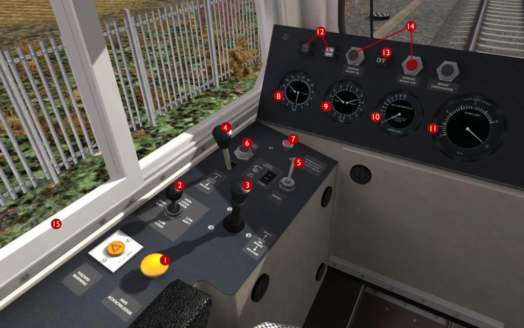
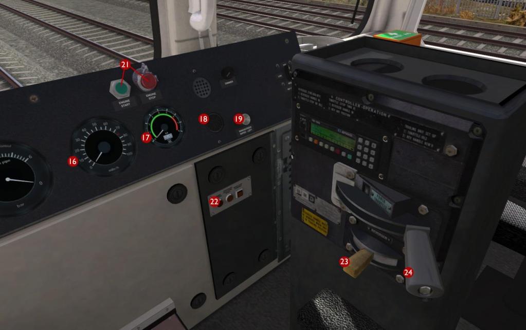
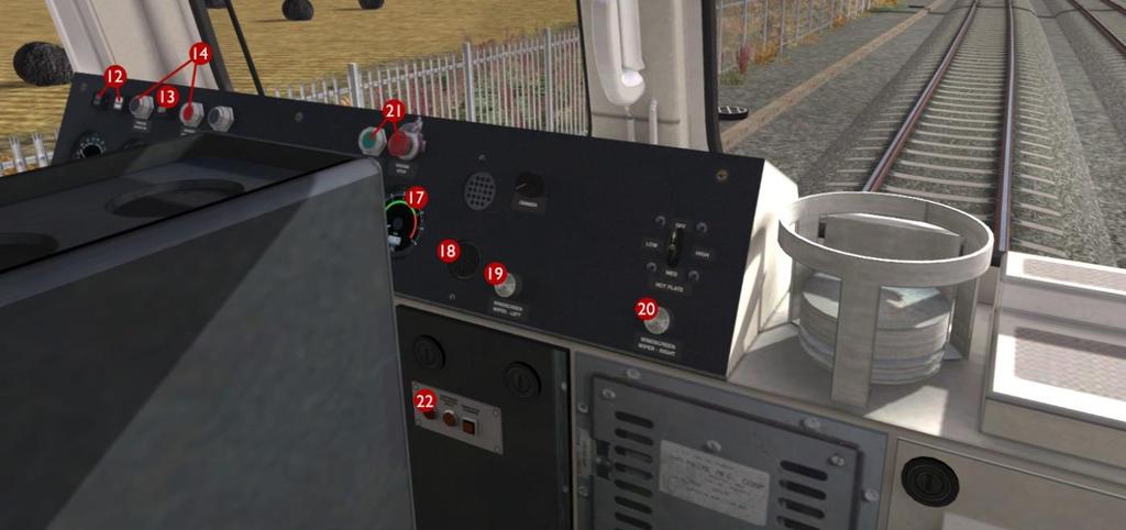
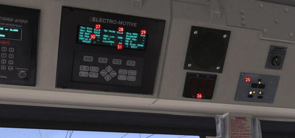
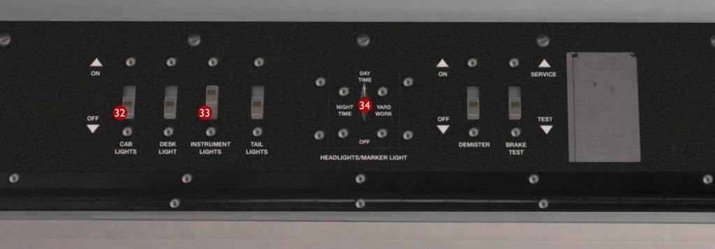
7 2.2 Design & Specification TOPS Number Range Class Wheel Arrangement Co-Co Weight 126 tonnes Length 70ft 0½in (21.34m) Width 8ft 8¼ in (2.65m) Engine Type GM 12N-710G3B-EC Power at Rail 3,000hp (2,238kW) Max Speed 75mph (121km/h) Fuel Capacity 1,440 gallons (6,546 litres) Brake Types Air, Westinghouse PBL3 2.3 Cabin Controls - Refer to the illustrations on pages 8 and 9 1 AWS Reset 18 AWS Sunflower Display 2 Warning Horn 19 Driver s Wiper Control 3 Train PBL Air Brake 20 Second Man s Wiper Control 4 Direct Locomotive Air Brake 21 Engine Start and Stop Controls 5 Sander 22 AWS / TPWS Auto Brake Demand Lamp 6 Train Length Button 23 Reverser 7 Emergency Brake Plunger 24 Throttle 8 Main Reservoir and M.R. Pipe Pressure 25 Headlights / Tail Lights Proving Display 9 Bogie Brake Pressures 26 Wheelslip Fault Light 10 Brake Air Flow Indicator 27 Current Throttle Position 11 Brake Pipe Control Gauge 28 Current Reverser Position 12 Passenger / Goods Brake Timing 29 Engine RPM Display 13 Parking Brake Indicator 30 Tractive Effort Display 14 Parking Brake Controls 31 Digital Speedometer (mph) 15 Opening Side Window 32 Cab Light Switch 16 Speedometer (mph) 33 Instrument Lights Switch 17 Ammeter 34 Headlight Mode Switch (Tail Lights switch moves automatically according to the currently selected headlight mode) 2.4 Additional Keyboard Controls L Toggle Cab Light I Toggle Instrument Lights U Toggle Train Length Button Y Toggle Passenger/Goods Brake Timing V Toggle Left Wipers Switch CTRL+V Toggle Right Wipers Switch SPACE Horn High CTRL+SPACE Horn High Soft B Horn Low CTRL+B Horn Low Soft Note: The Train and Loco Brake levers (3 & 4) are not used when Train Simulator Driving Mode is configured for Simple Mode under Game Settings. Under this setting the throttle and brakes are controlled together from the Throttle Lever (24). Page 7
8 Page 8
9 Page 9
10 2.5 PBL Brake Levers Both the Train Air Brake and Loco Air Brake levers have three functional positions: - In the upright position they Hold the current brake pressure - When pulled fully back they gradually Release the brakes - When pushed fully forwards they gradually Apply the brakes The Train Brake lever is centre sprung both in the cabin and on the game HUD and the Loco Brake lever is only sprung forwards for brake application and can be left resting in the Release position when required. When using the Train Brake lever a target brake pressure can be selected as indicated by the outer needle on the Brake Pipe Control Gauge. The actual brake pressure will then gradually change to match the selected target as shown by the larger inner needle. The rate that the brake pressure changes is dictated by the brake timing selection ( Passenger or Goods ) as selected and indicated on the main console (item 12 shown on the previous page). When in Goods brake timing mode the brake pressure changes more slowly. 2.6 Train Length Button When a speed restriction sign indicates an increase in permissible line speed, the driver must ensure that the rear of the train has cleared this sign before increasing train speed. To assist the driver the Train Length Button is provided. To use this system press the button once when the driving cab is parallel with the sign, you will hear a single low audio tone to confirm the measurement system is active. Once the rear vehicle has cleared this same location the driver will hear two short audio tones to confirm this. 2.7 Automatic Warning System Self-test (AWS) When the reverser has been moved from OFF to Forward or Reverse for the first time, the automatic warning system self-test will commence. This is an audible continuous horn which is cancelled by pressing the AWS Reset button or Q on the keyboard. Page 10
 vehicles, a Trailer Composite Open (TCO) incorporating a first class section and a standard toilet and a Pantograph Trailer Standard Open")
11 3 The Class 350/1 Electric Multiple Unit 3.1 Train Overview The fleet of 30 x 4-car Class 350/1 trains are formed of vehicles originally ordered for Class 450/2 trains. Sets are formed of two Driving Motor Standard Open (DMOS) vehicles, a Trailer Composite Open (TCO) incorporating a first class section and a standard toilet and a Pantograph Trailer Standard Open (PTSO) with a disabled toilet and wheel chair area. In 2012 the fleet were uprated from 100 mph (161 km/h) to a top speed of 110 mph (177 km/h). The included Class 350/1 model features: Pantograph Arcing and Illumination Effects Neutral Section Functionality (compatible with WCML Over Shap route) Functional Passenger Information System (PIS) featuring: o Driver Selectable Destinations o Cabin PIS Display o Passenger Compartment Destination Display o Automatic Audio Station and Safety Announcements o Passenger Compartment Next Station Display (Synchronised with Announcements) Functional Train Management System (TMS) featuring: o Display of Current Train Configuration (4, 8 or 12 Car Graphic) o Clock Display o Headlight and Tail Lights Proving Display o Display of Dynamic Train Faults (including instructions to correct faults) o System Brightness Control Four state Headlight and Tail Light controls Functional DRA (Driver s Reminder Appliance) Functional Automatic Low Speed Button New Extended Cab system to allow movement from Cabin to Passenger Compartment Page 11
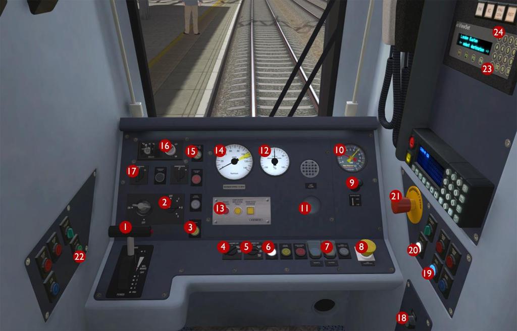
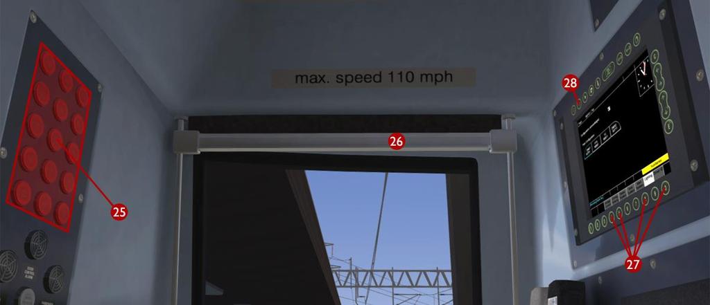
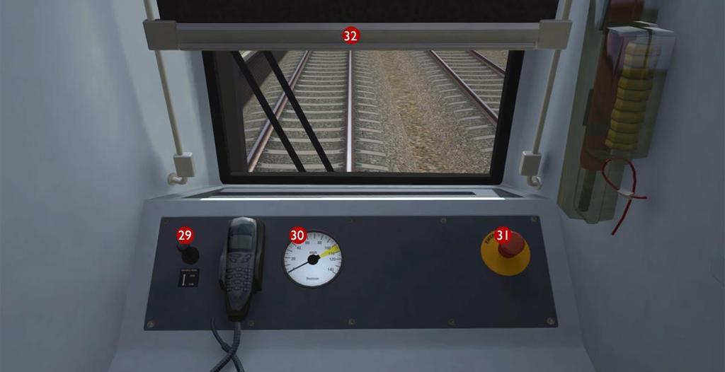
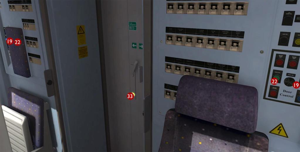
12 3.2 Design & Specification TOPS Number Range Class Formation 4-Car (DMSO+TCO+PTSO+DMSO) Weight (Total 4-Car) tonnes Vehicle Length 66ft 0¾in (20.34m) Width 9ft 2in (2.79m) Power Collection 25kV AC Overhead & 750V DC Third Rail Horsepower 1,341hp (1,000kW) Max Speed 110mph (177km/h) Brake Type Air, (regenerative) Coupling Type Outer Dellner, Inner - Bar 3.3 Cabin Controls - Refer to the illustrations on pages 13 and 14 1 Combined Throttle Brake Controller 18 Enable Second Man s Wiper Pushbutton 2 Reverser Switch 19 Doors Locked Interlock Lamp 3 Sander 20 Line Light Indicator 4 Cab and Instrument Lights Switch 21 Driver s Emergency Brake Plunger 5 Headlights / Tail Lights Mode Switch 22 Signal Bell 6 Tail Lights Indicator Lamp 23 PIS Destination Select Up 7 Low Speed Selector 24 PIS Destination Select Down 8 AWS Reset 25 Fault Indication Panel 9 Driver s Warning Horn 26 Driver s Sun Visor 10 Brake Cylinder / Main Reservoir Gauge 27 TMS Soft Selection Keys 11 AWS Sunflower 28 TMS Brightness Key 12 Braking / Traction Indicator 29 Second Man s Warning Horn 13 AWS / TPWS Auto Brake Demand Lamp 30 Second Man s Speedometer (mph) 14 Driver s Speedometer (mph) 31 Second Man s Emergency Brake Plunger 15 Pantograph / VCB Switch and Fault Lamp 32 Second Man s Sun Visor 16 DRA (Driver s Reminder Appliance) 33 Automatic Door to Passenger Compartment 17 Windscreen Wipers Switch 3.4 Additional Keyboard Controls L Increase Instrument and Cabin Lights Setting SHIFT+L Decrease Instrument and Cabin Lights Setting U Toggle Low Speed Button I Toggle DRA (Driver s Reminder Appliance) B Signal Bell V Toggle Wipers CTRL+V Toggle Enable SMS Wipers Switch M Increase PIS Destination Setting N Decrease PIS Destination Setting Page 12
13 Page 13
14 Page 14


15 3.5 Neutral Sections Roughly every 15 miles it is necessary to switch the electric supply to a different phase of the National Grid, in order to balance the load of the railway network across the three electrical phases. To avoid the possibility of bridging two phases, short Neutral Sections are used to separate electrified sections. Older AC electric locomotives can require special driving techniques on approach to neutral sections, however modern multiple units automate the transition through these sections. Neutral sections are marked for drivers with signs as shown above. A white -on-black sign marks the approach to the neutral section, giving drivers time to prepare the train to pass it. A black -on-white sign marks the beginning of the neutral section itself. Track magnets automatically open and close the train s main circuit breaker either side of the neutral section. Entering a neutral section under power is permitted but discouraged. Power will be instantly cut off, jolting your passengers. Do not stop your train within a neutral section. Neutral section locations are also marked on the route map on page DRA (Driver s Reminder Appliance) When the DRA switch is set to the on position (indicated by the switch illuminating red) traction power cannot be obtained. This is designed to help mitigate against the risk of signals being passed at danger after station stops where last signal passed was displaying a caution aspect. To obtain traction power again the driver must ensure the Throttle Brake Lever is in the brake position then switch off the DRA. If the Throttle Brake Lever is in a power notch then Page 15


16 it will need to be returned to the brake position before taking power. 3.7 Low Speed Button The Low Speed Button can be used for slow speed movements such as carriage washing. The button illuminates when operational and limits the power output from the Throttle Brake Controller to notch 1. It also automatically shuts off the power when the train reaches 2mph but it does NOT control the speed of the train. The driver must monitor the train speed and use the brake to reduce speed on falling gradients. Train Simulator 2015 WCML Trent Valley 3.8 Passenger Information System (PIS) The driver can cycle through available PIS destination displays using the left and right arrow soft -keys on the PIS panel in the cabin. When active these destinations and associated messages are displayed on the PIS panel, passenger compartment overhead display, DMOS body side displays and exterior train end displays as shown above. Passenger compartment overhead displays are updated for 60 seconds during audio announcements to show the next station stop. During career and quick drive scenarios, destination displays also get updated automatically when an audio announcement is broadcast. Page 16

17 Full PIS system technical information is provided at the end of this document for scenario writers. 3.9 Train Management System (TMS) The TMS provides information about the current state of the train. Above left it shows a current train formation of 8 cars and an analogue clock. Above right shows the exterior lighting page that provides the current state of the headlight and tail light lamps (th e display has also been dimmed in this image using the TMS Brightness Key). Real-time train faults are also displayed on the TMS screen when they occur along with instructions on how to correct the current fault. It is not possible to navigate away from a TMS fault screen until the current fault has been cleared Door Interlock The Doors Locked Interlock Lamp in the cabin illuminates with a blue light to indicate that all passenger doors are currently closed and locked. If any door is open then this b lue interlock light is extinguished and the train brake is automatically held on Automatic Warning System Self-test (AWS) When the reverser has been moved from OFF to Forward or Reverse for the first time, the automatic warning system self-test will commence. This is an audible continuous horn which is cancelled by pressing the AWS Reset button or Q on the keyboard. Page 17


18 3.12 Extended Cab System The Class 350 DMOS vehicles feature a new Extended Cab model that also incorporates the passenger compartment. This new system allows all cab audio including AWS warnings to be heard anywhere within the vehicle and enables camera positions to be linked together for movement around and between cabin and passenger compartments. The interconnecting automatic door is functional and can be opened by clicking on the illuminated door open button. As each DMOS vehicle in a train remembers the current camera position, it is possible to choose your preferred passenger compartment view in the rear DMOS vehicle then toggle between this view and the front cabin view using the Next and Previous Rail Vehicle buttons on the H UD or by pressing CTRL and + together on the keyboard. Page 18

19 Quick Drive 3.13 PIS On-train Announcements All included Quick Drive scenarios have been provided with Passenger Information System Announcements configured to operate when driving the Class 350/1 tr ain. When driving other trains and locomotives that are not equipped with a compatible on -board Passenger Information System you will not hear any announcements Speed Boards and the HUD On the West Coast Main Line there are EPS Speed Signs (Enhanced Permissible Speed) as well as the standard speed signs. When driving a Quick Drive scenario from the main menu you will always be shown the enhanced speeds on the HUD. If you have chosen to drive a multiple unit then these HUD speeds will apply to your train. If however you are driving a locomotive, you will need to obey the standard speed signs on the route. Please refer to the Speed Signs section of this manual for further information. Page 19


20 4 Signals 4.1 Main Signal Head Aspects Colour light signals are used for controlling running movements. They display aspects by means of red, yellow and green coloured lights. Signal Aspect Description Instruction to Driver Red light Danger Stop. Single yellow light Caution Proceed: be prepared to stop at the next signal. Double yellow lights Preliminary caution Proceed: be prepared to find the next signal displaying one yellow light. One flashing yellow light Double flashing yellow lights Preliminary caution for a diverging route Indication of diverging route ahead of the next but one signal Proceed: Be prepared to find the next signal displaying one yellow light with feather junction indicator for diverging route(s). Proceed: Be prepared to find the next signal displaying one flashing yellow light. Green light Clear Proceed: The next signal is displaying a proceed aspect. 4.2 Theatre Type Signals A Theatre alphanumeric route indicator indicates the route to be taken using numbers or letters (or a combination of numbers and letters). A Theatre indicator is often used to show the arrival platform number for a service. Page 20
 Feather Indication No Feather Indication Position 1 indication Position 2 indication Position 3 indication Position 4 indication Position 5 indication Position 6 indication")

21 4.3 Feather Type Signals A Feather junction indicator indicates a diverging route to be taken by the angle at which a line of five white lights is displayed. (Position 1 shown) Feather Indication No Feather Indication Position 1 indication Position 2 indication Position 3 indication Position 4 indication Position 5 indication Position 6 indication Instruction to Driver Obey main aspect, straight-ahead route is set Obey main aspect, expect divergence to left Obey main aspect, expect divergence to left more extreme than that for position 1 Obey main aspect, expect divergence to left more extreme than that for position 2 Obey main aspect, expect divergence to right Obey main aspect, expect divergence to right more extreme than that for position 4 Obey main aspect, expect divergence to right more extreme than that for position Ground Signals and Position Light Signals Ground Signals and Position Light Signals (PLS) display their aspects by means of the position and colour of lights. Ground Signals are always illuminated and can have miniature theatre indicators attached whereas PLS only illuminate to allow a train to pass in to an occupied section of line and are mounted as an addition to a main signal head. Signal Aspect Description Instruction to Driver Two red lights Danger Stop. No aspect (where associated with a main aspect) Obey main aspect. Two white lights Caution The line ahead may be occupied. Proceed cautiously towards the next stop signal, stop board or buffer stops. Be prepared to stop short of any obstruction. The associated main aspect (where provided) may be passed at danger Page 21


22 At Daventry International Rail Freight Terminal (DIRFT) there are fixed aspect danger signals on the departure and arrival lines. These ground mounted signals always display a main danger aspect, then in addition they display a PLS to allow a train to pass. If the PLS is not illuminated then you will need to contact the signaller for permission to pass. 4.5 Entering an Occupied Section of Track During a scenario your train may be scheduled to enter a platform or section of track that is already occupied by another train or rolling stock. In this situation you should stop at the red signal protecting this section of track as normal. Once your train has stopped pre ss the TAB key on your keyboard to request permission from the signalling centre to enter the occupied section of track. When your train movement is approved the signal will illuminate the two white lights on the position light signal if it has one. 4.6 Repeater Signals and Primary Route Indicators Standard banner repeater signals indicate whether the signal ahead is displaying a proceed aspect or is at danger. Modern fibre optic banner repeating signals, as shown above, consist of a rectangular unlit black background displaying a white circle with a black bar. In certain situations they can also illuminate in green to show that the signal ahead is also displaying a green (clear) aspect. Page 22

23 Arrows are referred to as primary route indicators and can be mounted separately or associated with a banner repeater signal. Primary route indicators repeat the feather direction of the signal ahead if it is displaying one. The examples above (from left to right) are indicating the signal ahead is: 1) Displaying a Red (Danger) aspect 2) Displaying a Green (Clear) aspect with no feather indicators 3) Displaying a Single or Double Yellow (Caution or Advanced Caution) with a left diversion feather Signal Display Horizontal arm White arm at an upper quadrant angle of 45 Green arm at an upper quadrant angle of 45 Instruction to Driver Be prepared to find the next signal at danger Next signal is exhibiting a proceed aspect Next signal is exhibiting a green (clear) aspect Repeater signals are intended to provide a driver with advance information of a signal that may be obscured on approach. A train does not need to stop at a repeater signal, only at the related signal if it is at danger. Splitting banner signals provide two banner signal heads combined to form a splitting banner repeating signal. These are also used to indicate the aspect of a signal with a feather junction indicator. If the related junction signal is displaying an illuminated feather then the lower banner head displays an arm at an upper quadrant angle of 45. Alternatively, if the related junction signal is not displaying an illuminated feather and is indicating a straight ahead route then the higher main banner head displays an arm at an upper quadrant angle of 45. Another type of repeater is an OFF platform indicator. Signal OFF indicators are provided to assist train dispatch staff. An OFF indicator displays the illuminated word OFF only when the signal to which it applies is displaying a proceed aspect. No indication is shown when the signal is at danger. Page 23


24 5 Speed Signs 5.1 Permissible Speed Indicators These signs display the permissible speed in miles per hour applicable to the section of line beyond the sign up to the commencement of any subsequent permissible speed section. Remember to wait for the complete length of your train to pass these signs before accelerating if the permissible line speed is increasing. If the permissible line speed is decreasing then you must reduce your speed before passing these signs. If there is an arrow provided in conjunction with the main sign then the permissible speed only applies to the diverting line indicated by the arrow. 5.2 Permissible Speed Warning Indicators These signs provide advance warning of a reduction in permissible speed ahead. Permanent AWS Ramps (Automatic Warning System) are often installed in conjunction with these signs. In these cases the driver must cancel the AWS warning when triggered on approach to these signs. See safety systems section of this manual. If there is an arrow provided in conjunction with the sign then the permissible speed warning only applies to the diverting line indicated by the arrow. 5.3 EPS Speed Indicators These signs indicate enhanced speeds for express trains on sections of the route. The sign on the left indicates a standard permissible speed of 100mph and an enhanced permissible speed of 125mph for express services. The yellow sign on the right provides an advanced warning of a reduction in enhanced permissible speed ahead and can be ignored by non-express services. Page 24


25 5.4 Temporary Speed Restrictions Warning Board Speed Indicator Termination Indicator Direction of Travel 20 M.P.H. Speed Restriction Temporary speed restrictions are normally put in place when engineering works and track maintenance is taking place. These temporary speed restrictions are advised in the drivers weekly operating notice and in this simulation are advised in your scenario briefing. The normal sequence of trackside signage is shown above. However, when line speeds need to be reduced at short notice they are referred to as an Emergency Speed Restriction and are additionally protected by providing an Emergency Indicator prior to the temporary speed restriction warning board. The emergency indicator has two synchronous flashing white lights. Temporary Sign Description Instruction to Driver Emergency Indicator This sign warns that there is a warning board ahead for an emergency speed restriction that has not been previously advised. Warning Board This sign provides warning of a restriction speed indicator ahead. Repeater Warning Board Restriction Directional Arrow Restriction Speed Indicator Restriction Termination Indicator Restriction Spate Indicator This sign provides a reminder of a restriction speed indicator ahead. It is normally used where a driver has set off from a platform after passing a warning board This sign is always associated with either a warning board, a speed indicator or a spate indicator. This sign indicates the start of a temporary speed restriction with the value shown in M.P.H. You must reduce your speed before passing these signs. This sign identifies the end of a temporary speed restriction. Remember to wait for the complete length of your train to pass this sign before accelerating back to normal line speed. This sign identifies that the temporary speed restriction, at that location as previously advised, is now not in force. Page 25
 AWS is provided to give train drivers in-cab warnings of the approach to signals, reductions in permissible speed and temporary/emergency speed restrictions, and to")
26 6 Safety Systems 6.1 AWS (Automatic Warning System) AWS is provided to give train drivers in-cab warnings of the approach to signals, reductions in permissible speed and temporary/emergency speed restrictions, and to apply the brakes in the event that a driver does not acknowledge cautionary warnings given by the system. As a train approaches a signal or track sign, it passes over AWS track equipment (magnets) which are fixed to the sleepers between the running rails. The magnets are sensed by a receiver mounted under the leading end of the train. If the signal ahead is displaying a clear aspect (green), a bell (or an electronic ping) sounds in the driver s cab, and the AWS Sunflower indicator displays all black. No action in respect of the AWS is required of the driver. If the signal is displaying a caution or danger aspect (yellow, double yellow or red), a horn sounds in the driver s cab and the display shows all black. The driver has to acknowledge the warning by pressing the AWS Acknowledgement (AWS Reset) push button. When the driver operates the push button, the horn is silenced and the AWS Sunflower changes to a segmented yellow and black circular display. If the driver fails to acknowledge the warning horn within a set time period, the emergency brakes are applied automatically. Where permanent warning AWS equipment is provided on the approach to reductions in permissible speed, fixed warning boards and speed restrictions, the cab equipment always operates in a manner equivalent to the approach to a signal displaying a caution or stop aspect. The driver receives a warning and has to respond to it accordingly; otherwise the emergency brakes are applied automatically. Page 26
.")
27 6.2 TPWS (Train Protection and Warning System) General Overview The primary purpose of TPWS is to minimise the consequence of a train passing a TPWS fitted signal at danger and a train over speeding on approach to a TPWS fitted signal at danger. TPWS track equipment is only active when the signal that they are protecting is displaying a danger aspect (red). Protected Signal AWS Magnets Overspeed Sensor Train Stop Sensor Note: AWS Magnets are normally positioned approx. 150m prior to signal and TPWS OSS Equipment prior to that. There are two pairs of grids mounted between the running rails. Both pairs consist of an 'arming' and a 'trigger' grid. The first pair, the Overspeed Sensor (OSS), are positioned on approach to the protected signal. The other pair of grids are mounted back to back at the signal location, and these form the Train Stop Sensor (TSS). The emergency train brakes are automatically applied if a train passes over an active Overspeed Sensor faster than a predetermined speed for that location. The brakes are also applied if a train passes over an active Train Stop Sensor at any speed, as the signal it is protecting m ust be at danger. After passing a signal displaying a caution aspect (single yellow) it is advisable to reduce your train speed to anticipate the approach to the next signal. It may be at danger and therefore the TPWS Overspeed Sensor will be active and will trip an emergency stop if your train speed is greater than the predetermined approach speed when you pass over it. Many platforms with buffer stops are protected by Mini-Overspeed Sensors (usually set with a trigger speed of around 12mph). It is advisable to enter these platforms no faster than 10mph. Page 27


28 7 Scenario Creation Guidance The passenger information system developed for the Class 350/1 train operates with the use of invisible track linked triggers placed in each scenario. It is essential that these are not placed in the route editor, they must ONLY be placed in the scenario editor. There is only one type of trigger named PIS and TMS AutoSetup and this can be found in the scenario editor under the Miscellaneous section (brown bag icon) as shown below. After placing a trigger where you want the event to take place you need to enter a six digit number in to the dialog box on the right of the scenario editor as shown above, then press enter to save the entry. If you need to change the number never try to edit it delete the trigger and add a new one otherwise your changes will not be saved. The numbering system is explained below. The first two digits are a code for an on-board audio announcement (shown in blue), the second two digits are a code to set the destination displays (shown in green), the fifth digit is to trigger an onboard train fault and the sixth digit is the probability of this fault occurring. Probability works on the basis 0=never, 1=always, 2=50/50 chance and 3 to 9 become progressively less likely. Details of actual fault codes are not provided in this manual. Please refer to Section 9 Terms & Conditions. Page 28


29 8 Procedural Flora This route has been designed making full use of the simulator s procedural flora func tionality. We have designed all new ground textures that feature shrubs and grasses. To make these visible and get the best visual experience of the route we advise that you turn this feature on in the main settings menu as shown below. If you are running a less powerful computer you may get an increase in performance if you turn this setting off. Page 29
30 9 Content Creators - Terms and Conditions 9.1 End User License Agreement (EULA) This product is published by Railsimulator.com Ltd (trading as Dovetail Games) and distributed by Valve through their Steam online stores and distribution system. By purchasing and using this product you are bound by Valve s Software License. In addition to these terms, Thomson Interactive Ltd prohibits any commercial use or involvement of their products i n third party commercial products unless prior written consent is sought and granted. 9.2 Commercial Add-ons and Scenario Packs Thomson Interactive Ltd. Do not allow the development or sale of any commercial add-ons or associated products including but not limited to: Scenario Packs Route Enhancement Patches Audio Enhancement Packs If you are interested in working with us please contact us through our web site. 9.3 Workshop Scenarios We encourage the non-commercial creation of scenarios for our routes as long as they are distributed through the Steam Workshop. Page 30
31 10 Acknowledgements This route was developed in partnership with Keith Ross, the developer of many other Train Simulator routes including the West Coast Mainline and Western Lines of Scotland. The fidelity we have achieved would not have been possible without Keith s incredible attention to detail and sheer hard work during the project. We would like to thank Direct Rail Services for their permission to use their branding on the Class 66 locomotive livery and shipping containers included with this product. - end - Page 31
Class 66 Diesel Locomotive Pack 02 Add-on
 Class 66 Diesel Locomotive Pack 02 Add-on 1 BACKGROUND... 2 1.1 Class 66... 2 1.2 Technical Specification... 2 2 LOCOMOTIVE AND ROLLING STOCK... 3 2.1 Freightliner Class 66 Locomotive... 3 2.2 FEA-B Spline
Class 66 Diesel Locomotive Pack 03 Add-on
 Class 66 Diesel Locomotive Pack 03 Add-on 1 BACKGROUND... 2 1.1 Class 66... 2 1.2 Technical Specification... 2 2 LOCOMOTIVE AND ROLLING STOCK... 3 2.1 EWS Class 66 Locomotive... 3 2.2 JGA Aggregate Hopper
BR 266 Diesel Locomotive
 BR 266 Diesel Locomotive 1 BACKGROUND... 3 1.1 History... 3 1.2 Design & Specification... 3 2 ROLLING STOCK... 4 2.1 BR266... 4 2.2 Megafret container wagons... 4 3 DRIVING THE BR266... 6 3.1 Cab Controls...
RhB Enhancement Pack 2
 Train Simulator 2017 RhB Enhancement Pack 2 1 THE GE 4/4 II LOCOMOTIVE... 3 1.1 Locomotive History... 3 1.2 Design & Specification... 3 1.3 Cabin Controls - Refer to the illustrations on page 4... 3 1.4
BR266 Diesel Locomtoive
 BR266 Diesel Locomtoive 1 BACKGROUND... 3 1.1 History... 3 1.2 Design & Specification... 3 2 ROLLING STOCK... 4 2.1 BR266... 4 2.2 Megafret container wagons... 4 3 DRIVING THE BR266... 6 3.1 Cab Controls...
Train Simulator 2015 EMD FL9. New Haven EMD FL9. Copyright Dovetail Games 2015, all rights reserved Release Version 1.0. Page 1
 New Haven EMD FL9 Page 1 1 BACKGROUND... 3 1.1 Loco... 3 1.2 Design & Specification... 3 2 ROLLING STOCK... 4 2.1 EMD FL9... 4 2.2 Metro-North Shoreliner III Cab car and Passenger car... 4 3 DRIVING THE
Class 455/9 Electric Multiple Unit
 Class 455/9 Electric Multiple Unit 1 BACKGROUND... 2 1.1 Class 455/9... 2 1.2 Design & Specification... 2 2 THE CLASS 455/9 ELECTRIC MULTIPLE UNIT... 2 2.1 SWT Livery... 2 2.2 NSE Livery... 3 2.3 BR Livery...
InterCity BR Class 370 'Advanced Passenger Train - Prototype'
 InterCity BR Class 370 'Advanced Passenger Train - Prototype' Page 1 1 BACKGROUND...4 1.1 InterCity BR Class 370 'Advanced Passenger Train - Prototype'...4 1.2 Class 370 APT-P Design & Specification...4
Class 444 Electric Multiple Unit
 Class 444 Electric Multiple Unit 1 BACKGROUND...2 Class 444 Electric Multiple Unit...2 2 ROLLING STOCK...3 2.1 South West Trains Express White Livery...3 3 DRIVING THE CLASS 444 EMU...6 3.1 Cab Diagram...6
ÖBB Copyright Dovetail Games 2016, all rights reserved Release Version 1.0
 ÖBB 4020 1 BACKGROUND... 4 1.1 Loco... 4 1.2 Design & Specification... 4 2 ROLLING STOCK... 5 2.1 ÖBB 4020... 5 2.2 ÖBB 4020 New Logo... 6 2.3 ÖBB 4020 Red Grey... 7 3 DRIVING THE ÖBB 4020... 8 3.1 Cab
GEML Class 90. Contents. Page 1
 GEML Class 90 Contents Technical information... 2 Liveries... 3 Class 90... 3 Mk3 DVT... 5 Mk3 coaches (FO, RFB & SO)... 7 Cab guide... 8 Keyboard controls... 10 Features... 11 Advanced and HUD versions...
Class 220 Voyager. Copyright Dovetail Games 2014, all rights reserved Release Version 1.0
 Class 220 Voyager 1 BACKGROUND... 3 1.1 Class 220 Voyager...3 1.2 Design & Specification...4 2 ROLLING STOCK... 5 3 DRIVING THE CLASS 220 VOYAGER... 7 3.1 Cab Controls...7 3.2 Locomotive Keyboard Controls...9
CLASS 377. Copyright RailSimulator.com 2012, all rights reserved Release Version 1.0
 CLASS 377 1 BACKGROUND......... 3 1.1 Class 377...3 1.2 Design & Specification...3 1.3 Class 377 Consist Formations...3 2 ROLLING STOCK...... 4 3 CREATING A CLASS 377 TRAIN SET..... 7 3.1 Scenario Editor
DB BR114. Copyright Dovetail Games 2016, all rights reserved Release Version 1.0
 DB BR114 1 BACKGROUND... 3 1.1 BR114... 3 1.2 Design & Specification... 3 2 ROLLING STOCK... 4 2.1 BR114... 4 2.2 Doppelstockwagen... 4 3 DRIVING THE BR114... 6 3.1 Cab Controls... 6 3.2 Locomotive Keyboard
Class 180 (Adelante) Copyright Dovetail Games 2015, all rights reserved Release Version 1.0
 Copyright Dovetail Games 2015, all rights reserved Release Version 1.0") Class 180 (Adelante) 1 BACKGROUND... 3 1.1 Class 180 (Adelante)... 3 1.2 Design & Specification... 3 2 ROLLING STOCK... 4 2.1 DMSL A (B)... 4 2.2 MFL (F)... 4 2.3 MSL (E)... 5 2.4 MSLRB (C)... 5 2.5 DMSL
Class 180 (Adelante) 1 BACKGROUND... 3 1.1 Class 180 (Adelante)... 3 1.2 Design & Specification... 3 2 ROLLING STOCK... 4 2.1 DMSL A (B)... 4 2.2 MFL (F)... 4 2.3 MSL (E)... 5 2.4 MSLRB (C)... 5 2.5 DMSL
Class 220 Voyager. Copyright Dovetail Games 2015, all rights reserved Release Version 1.0
 Class 220 Voyager 1 BACKGROUND... 3 1.1 Class 220 Voyager...3 1.2 Design & Specification...4 2 ROLLING STOCK... 5 3 DRIVING THE CLASS 220 VOYAGER... 7 3.1 Cab Controls...7 3.2 Locomotive Keyboard Controls...9
DB Class 424 Electrical Multiple Unit
 DB Class 424 Electrical Multiple Unit 1 THE CLASS 424...2 1.1 Class 424 EMU...2 1.2 Technical Specification...2 2 ROLLING STOCK...3 2.1 DB BR424...3 3 CAB CONTROLS...4 3.1 Controls...4 3.2 Keyboard Guide...5
Class 605 ICE TD. Copyright Dovetail Games 2014, all rights reserved Release Version 1.0
 Class 605 ICE TD 1 Background... 3 Multiple Unit... 3 Design & Specification... 3 2 Rolling Stock... 4 Class 605 ICE TD... 4 3 Driving the ICE TD... 5 Cab Controls... 5 Keyboard Controls... 6 General Keyboard
DB BR261 - Voith Gravita 10BB
 DB BR261 - Voith Gravita 10BB 1 BACKGROUND... 3 1.1 Loco...3 1.2 Design & Specification...3 2 ROLLING STOCK... 4 2.1 DB BR261 Voith Gravita...4 2.2 Zacns 95m Tanker...4 2.3 Rnoos 644...5 2.4 Cab Controls...6
Class 87 Electric Locomotive
 Class 87 Electric Locomotive 1 BACKGROUND...2 1.1 Class 87 Overview...2 1.2 Class 87 Origins...2 1.3 Technical Specification...2 2 THE CLASS 87 INTERCITY EXECUTIVE...3 2.1 Class 87 in Intercity Executive
Class 91/Mk4 Enhancement Pack
 Class 91/Mk4 Enhancement Pack Contents How to install... 2 Liveries... 3 Keyboard controls... 6 Features... 7 Dynamic brake simulation... 8 Speed set cruise control... 8 Neutral section functionality...
Class 90 (Freightliner)
") Class 90 (Freightliner) Contents How to install... 2 Technical information... 3 Liveries... 4 Class 90... 4 Cab guide... 5 Keyboard controls... 7 Features... 8 Braking system (rheostatic/air)... 9 Train
Class 90 (Freightliner) Contents How to install... 2 Technical information... 3 Liveries... 4 Class 90... 4 Cab guide... 5 Keyboard controls... 7 Features... 8 Braking system (rheostatic/air)... 9 Train
Arriva Trains Wales DMU Pack
 Arriva Trains Wales DMU Pack 1 BACKGROUND... 3 1.1 Class 158... 3 1.2 Design & Specification... 3 1.3 Class 143... 3 1.4 Design & Specification... 3 2 ROLLING STOCK... 4 2.1 Class 158 Arriva Trains Wales...
North Jersey Coast Line
 North Jersey Coast Line Page 1 1 ROUTE INFORMATION...... 4 1.1 The Route... 4 1.2 Focus Time Period... 4 2 GETTING STARTED...... 5 2.1 Recommended Minimum Hardware Specification... 5 3 ROLLING STOCK.........
DB BR152. Copyright Dovetail Games 2015, all rights reserved Release Version 1.0
 DB BR152 1 BACKGROUND... 3 1.1 Loco... 3 1.2 Design & Specification... 3 2 ROLLING STOCK... 4 2.1 DB BR152... 4 3 DRIVING THE BR152... 5 3.1 Cab Controls and image... 5 3.2 Keyboard Controls... 7 3.3 General
Preparation and movement of trains Defective or isolated vehicles and on-train equipment Issue 7
 GERT8000-TW5 Rule Book Module TW5 Preparation and movement of trains Defective or isolated vehicles and on-train equipment Issue 7 September 2016 Comes into force 03 December 2016 Published by: RSSB The
MRCE ES64U2 ELECTRIC LOCOMOTIVE. Copyright RailSimulator.com 2013, all rights reserved Release Version 1.0
 MRCE ES64U2 ELECTRIC LOCOMOTIVE 1 BACKGROUND......... 3 1.1 ES64 U2...3 1.2 Design & Specification...3 2 ROLLING STOCK...... 4 2.1 MRCE ES64 U2...4 2.2 SGGRSS Wagon...4 3 DRIVING THE ES64 U2...... 5 3.1
Class 350 Enhancement Pack
 Class 350 Enhancement Pack Contents How to Install... 2 Liveries... 3 Keyboard Controls... 7 Features... 8 Train Management System (TMS)... 9 Train Protection and Warning System (TPWS) Mk4... 14 Uncoupling
HHP-8 Electric Locomotive
 HHP-8 Electric Locomotive 1 BACKGROUND......... 3 1.1 Loco...3 1.2 Design & Specification...3 2 ROLLING STOCK...... 4 2.1 HHP-8 Electric Locomotive...4 2.2 Amcoach...5 2.3 Amcafe...5 3 DRIVING THE HHP-8.........
Issue 8. Module TW5. Preparation and movement of trains: Defective or isolated vehicles and on-train equipment. GERT8000-TW5 Rule Book
 GERT8000-TW5 Rule Book Preparation and movement of trains: Defective or isolated vehicles and on-train equipment Issue 8 Module TW5 September 2017 Comes into force 02 December 2017 Conventions used in
Class 24 BR Blue. Copyright Dovetail Games 2015, all rights reserved Release Version 1.0
 Class 24 BR Blue 1 BACKGROUND... 3 1.1 Class 24... 3 1.2 Design & Specification... 3 2 ROLLING STOCK... 4 2.1 Class 24... 4 2.2 BR Blue Mk1 FK... 4 2.3 BR Blue Mk1 SK... 5 2.4 BR Blue Mk1 BG... 5 2.5 Hopper
London Overground Class 313 EMU
 London Overground Class 313 EMU Page 1 Contents Technical information... 3 Cab guide... 4 Keyboard controls... 6 Features... 7 Advanced and HUD versions... 8 Camshaft traction system... 9 Driver only/guard
ALP-46 New Jersey Transit
 ALP-46 New Jersey Transit 1 BACKGROUND... 3 1.1 Loco... 3 1.2 Design & Specification... 3 1.3 Multi-Level Cab car... 4 1.4 Design & Specification... 4 2 ROLLING STOCK... 5 2.1 NJT ALP-46... 5 2.2 Comet
East Coast Mainline. Copyright RailSimulator.com 2012, all rights reserved Release Version 1.0
 East Coast Mainline CONTENTS 1 ROUTE INFORMATION...... 3 2 ROLLING STOCK......... 4 2.1 Locomotives...4 2.1.1 Class 55 Deltic Locomotive...4 2.1.2 Class 47 'Spoon Locomotive...5 2.1.3 IC125 High Speed
Withdrawn Document Uncontrolled When Printed. SP (issue 1).qxd 16/4/03 1:04 pm Page 1. Module SP. GE/RT SP Rule Book. Speeds. Issue 1.
.qxd 16/4/03 1:04 pm Page 1. Module SP. GE/RT SP Rule Book. Speeds. Issue 1.") SP (issue 1).qxd 16/4/03 1:04 pm Page 1 GE/RT8000 - SP Rule Book Module SP Speeds Issue 1 June 2003 Comes into force 6 December 2003 SP (issue 1).qxd 16/4/03 1:04 pm Page 2 Issue Date Comments Comes into
SP (issue 1).qxd 16/4/03 1:04 pm Page 1 GE/RT8000 - SP Rule Book Module SP Speeds Issue 1 June 2003 Comes into force 6 December 2003 SP (issue 1).qxd 16/4/03 1:04 pm Page 2 Issue Date Comments Comes into
Lineside Signal Spacing and Speed Signage
 Document comes into force and supersedes GKRT0075 Iss 3 on 05/12/15 With effect from 03/03/18 parts of this document have been superseded by Date September 15 Lineside Signal Spacing and Speed Synopsis
BR Class 105. Copyright Dovetail Games 2015, all rights reserved Release Version 1.0
 BR Class 105 1 BACKGROUND... 3 1.1 Loco... 3 1.2 Design & Specification... 3 2 ROLLING STOCK... 4 2.1 BR Class 105 DMBS... 4 2.2 BR Class 105 DTCL... 4 3 DRIVING THE BR CLASS 105... 5 3.1 Cab Controls...
F40PH-2CAT New Jersey Transit
 F40PH-2CAT New Jersey Transit 1 BACKGROUND... 3 1.1 Loco... 3 1.2 Design & Specification... 3 2 ROLLING STOCK... 4 2.1 F40PH-2CAT... 4 2.2 Comet IV... 4 2.3 Comet V Cab Car... 5 3 DRIVING THE F40PH-2CAT...
CLASS 56. Railfreight Sectors. Copyright Dovetail Games 2014, all rights reserved Release Version 1.0
 CLASS 56 Railfreight Sectors 1 BACKGROUND... 3 Class 56 Locomotive...3 Design & Specification...3 ROLLING STOCK 4 Class 56 Railfreight Sectors...4 2 DRIVING THE CLASS 56 DIESEL LOCOMOTIVE... 5 Cab Controls...5
BR Blue Diesel Electric Pack Classes 09/33/73/416/421
 BR Blue Diesel Electric Pack Classes 09/33/73/416/421 1 BACKGROUND... 3 1.1 Class 09... 3 1.2 Class 33... 4 1.3 Class 73... 5 1.4 Class 416 2EPB... 6 1.5 Class 421 4CIG... 7 2 ROLLING STOCK... 8 2.1 OBA
London Transport Heritage Collection
 London Transport Heritage Collection 1 ROLLING STOCK... 4 1.1 Class 20... 4 1.1.1 Background...4 1.1.2 Design & Specification...5 1.2 Pannier 5700 Class... 5 1.2.1 Background...6 1.2.2 Design & Specification...6
PENINSULA CORRIDOR SAN FRANCISCO - GILROY. Copyright Dovetail Games 2016, all rights reserved Release Version 1.1. Page 1
 PENINSULA CORRIDOR SAN FRANCISCO - GILROY Copyright Dovetail Games 2016, all rights reserved Release Version 1.1 Page 1 ROUTE INFORMATION... 4 The Route... 4 Focus Time Period... 4 GETTING STARTED... 5
Arriva Trains Wales DMU Pack
 Arriva Trains Wales DMU Pack 1 BACKGROUND...... 3 1.1 Class 158...3 1.2 Class 143...3 2 ROLLING STOCK... 4 2.1 Class 158 Arriva Trains Wales...4 2.2 Class 143 Arriva Trains Wales...4 3 DRIVING THE CLASS
Railworks Austria Skyhook Games ÖBB 1014 Manual
 Railworks Austria Skyhook Games ÖBB 1014 Manual Page 1 Index Introduction Page 3 1014 cab and key bindings Page 4 Train Operation Start-up procedure Page 8 Driving procedures Page 9 PZB/Indusi How does
GE ARROW III NJ TRANSIT
 GE ARROW III NJ TRANSIT 1 BACKGROUND... 4 1.1 Loco... 4 1.2 Design & Specification... 4 2 ROLLING STOCK... 5 2.1 Arrow III A Car... 5 2.2 Arrow III B Car... 5 3 DRIVING THE ARROW III... 6 3.1 Cab Controls
Miami Commuter Rail F40PHL-2
 Miami Commuter Rail F40PHL-2 1 BACKGROUND... 3 1.1 Loco...3 1.2 Design & Specification...3 2 ROLLING STOCK... 4 2.1 F40PHL-2...4 2.2 Coaching Stock...4 3 DRIVING THE F40PHL-2... 6 3.1 Cab Controls...6
Issue 9. Module TW5. Preparation and movement of trains: Defective or isolated vehicles and on-train equipment. GERT8000-TW5 Rule Book
 GERT8000-TW5 Rule Book Preparation and movement of trains: Defective or isolated vehicles and on-train equipment Issue 9 Module TW5 September 2018 Comes into force 01 December 2018 Conventions used in
Class 455/8 Southern. Copyright Dovetail Games 2015, all rights reserved Release Version 1.0
 Class 455/8 Southern 1 BACKGROUND... 3 1.1 The Multiple Unit... 3 1.2 Design & Specification... 3 2 ROLLING STOCK... 4 2.1 Unit List... 4 3 DRIVING THE CLASS 455/8... 6 3.1 Cab Controls... 6 3.2 Locomotive
Module SP. Speeds. GE/RT8000/SP Rule Book. Issue 5. September 2015
 GE/RT8000/SP Rule Book Module SP Speeds Issue 5 September 2015 Comes into force 05 December 2015 Published by: RSSB The authoritative version of this document is available at www.rssb.co.uk/rgsonline Contents
Great Western Mainline
 Great Western Mainline CONTENTS 1 ROUTE INFORMATION...... 3 1.1 History...3 2 ROLLING STOCK......... 4 2.1 Locomotives...4 2.1.1 IC125 High Speed Train...4 2.1.2 Class 166 Thames Turbo DMU...5 2.1.3 Class
Amtrak Dash 8-32BWH. Copyright Dovetail Games 2016, all rights reserved Release Version 1.0
 Amtrak Dash 8-32BWH 1 BACKGROUND...... 3 1.1 Loco...3 1.2 Design & Specification...3 2 ROLLING STOCK...... 4 2.1 Amtrak Dash 8-32BWH...4 2.2 Amtrak Dash 8-32BWH Phase III...4 2.3 Amtrak Baggage Heritage...5
TS2017 DLC. Western Sichuan Pass V1.0. By Liu Fei. Simtech Vision Product
 TS2017 DLC Western Sichuan Pass V1.0 By Liu Fei Simtech Vision Product TS2017 DLC TABLE OF CONTENTS Introduction... 2 Route specification... 2 Features... 3 Stations... 3 LKJ Signaling system... 4 Rolling
Route Guide. Route expansion for Train Simulator S-Bahn Rhein-Main Route Guide
 ROUTE GUIDE Route Guide Route expansion for Train Simulator 2018 2 CONTENTS INTRODUCTION...4 Route...4 Services...5 Depots and Sidings...6 NOTES ON USING THE ROUTE...7 Train Simulator Display Settings...7
TRAIN SIM WORLD : NORTHERN TRANS-PENNINE DRIVER S MANUAL
 TRAIN SIM WORLD : NORTHERN TRANS-PENNINE DRIVER S MANUAL 1 2018 Dovetail Games, a trading name of RailSimulator.com Limited ( DTG ). All rights reserved. "Dovetail Games", Train Sim World and SimuGraph
GM/GN2169. Combined Manual for AWS and TPWS Trainborne Equipment. Railway Group Guidance Note. Issue One: April Uncontrolled When Printed
 GN Published by Rail Safety and Standards Board Evergreen House 160 Euston Road London NW1 2DX Copyright 2007 Rail Safety and Standards Board Limited GM/GN2169 Issue One: April 2007 Railway Group Guidance
Class 43 (Valenta)/Mk3 Enhancement Pack
/Mk3 Enhancement Pack") Class 43 (Valenta)/Mk3 Enhancement Pack Contents How to install... 2 Liveries... 3 Keyboard controls... 13 Features... 14 Automatic Train Protection (ATP)... 15 Speed limit display... 15 Brake intervention...
Class 43 (Valenta)/Mk3 Enhancement Pack Contents How to install... 2 Liveries... 3 Keyboard controls... 13 Features... 14 Automatic Train Protection (ATP)... 15 Speed limit display... 15 Brake intervention...
DB BR361/V60. Copyright Dovetail Games 2015, all rights reserved Release Version 1.0
 DB BR361/V60 1 BACKGROUND... 3 1.1 BR361/V60... 3 1.2 Design & Specification... 4 2 ROLLING STOCK... 5 2.1 BR361/V60... 5 2.2 SGGRSS Freight Wagons... 5 3 DRIVING THE BR361/V60... 6 3.1 Cab Controls...
FP7 California Zephyr
 FP7 California Zephyr 1 BACKGROUND... 3 1.1 EMD FP7 Western Pacific...3 1.2 EMD F7 Rio Grande...5 2 ROLLING STOCK... 6 2.1 California Zephyr cars...6 2.2 Rio Grande Zephyr cars...6 3 DRIVING THE LOCOMOTIVES...
Centralised Traffic Control System - Rules 1 to 17
 Centralised Traffic Control System - Rules 1 to 17 Applicability VIC Publication Requirement External Only Document Status Issue/Revision # Effective from 2 13 May 2012 0 04 October 2015 Australian Rail
Class 45/46 Peak Diesel Locomotives 1 BACKGROUND...2
 Class 45/46 Peak Diesel Locomotives 1 BACKGROUND...2 1.1 Class 45/46 Heritage...2 1.2 Sulzer 12LDA28B Diesel engine...3 1.3 Nose End Variations...3 1.4 Design and Specification...4 2 THE CLASS 45/46 DIESEL
BR CLASS 156 DMU DRIVING MANUAL
 BR CLASS 156 DMU DRIVING MANUAL 1. Background 2. Technical information 3. Liveries 4. Key features 5. Switches, buttons and functionalities 6. Headlight system 7. Destination display 8. Scenarios 9. Keyboard
1 BACKGROUND Deltic Prototype History Deltic Prototype Operation Technical Specification ROLLING STOCK...
 Deltic Prototype 1 BACKGROUND...2 1.1 Deltic Prototype History...2 1.2 Deltic Prototype Operation...2 1.3 Technical Specification...3 2 ROLLING STOCK...3 2.1 DP1 'Deltic'...3 2.2 Mk1 Coach Set...4 3 CAB
CRH2A EMU Driver Manual Ver. 1.2
 CRH2A EMU Driver Manual Ver. 1.2 This manual is only for use with the Train Simulator game and is not for real-world use. 1 / 24 Table of Contents 1 Brief Introduction to CRH2A EMU... 3 2 About This Add-On...
Southern Railway s15 Class
 Southern Railway s15 Class 1 BACKGROUND... 3 1.1 SR S15 Class... 3 1.2 Design & Specification...3 2 ROLLING STOCK... 4 2.1 SR S15 Locomotive SR Olive Green...4 2.2 SR S15 Locomotive SR Black...4 2.3 SR
Uncontrolled when printed Supersedes GERT8000-RBBL Iss 31.1 with effect from 01/12/2018. Rule Book Briefing Leaflet. Issue 32
 Rule Book Briefing Leaflet Issue 32 December 2018 The following modules and handbooks will be reissued and come into force on 01 December 2018: Glossary Glossary of Railway Terminology Handbook 8 IWA,
Locomotive Driver Desk. Manual
 Locomotive Driver Desk Manual Authors: Dr.-Ing. T. Vaupel, D. Richter, M. Berger Translated by Wolfram Steinke Copyright Uhlenbrock Elektronik GmbH, Bottrop 3rd Edition March 2004 All Rights Reserved Duplication
F40 Locomotive Operating Manual
 F40 Locomotive Operating Manual 1. Introduction The HP-Trainz team developed very detailed 3D-model of the American diesel-electric locomotive F40 for the use in the railway simulator Trainz. Beside the
The Class 111 Diesel Multiple Unit
 The Class 111 Diesel Multiple Unit 1 BACKGROUND...2 Class 111 Diesel Mechanical Multiple Unit...2 2 ROLLING STOCK...3 2.1 BR Green DMBS...3 2.2 BR Green DTCL...3 3 DRIVING THE CLASS 111 DMU...4 3.1 Cab
Network Safeworking Rules and Procedures
 Network Safeworking Rules and Procedures Shunting and Marshalling Rule Number: 4013 Version 1.0, 31 March 2016 Shunting and Marshalling Rule Number: 4013 Document Control Identification Document title
Rapid Response. Lineside Signal Spacing. Railway Group Standard GK/RT0034 Issue Three Date September 1998
 Rapid Response Railway Group Standard Lineside Signal Spacing Synopsis This Standard specifies the minimum distance that must be provided between the first signal displaying a cautionary aspect and the
Network Safeworking Rules and Procedures
 Network Safeworking Rules and Procedures s Rule Number: 3025 Version 1.0, 31 March 2016 Temporary Speed Restrictions Rule Number: 3025 Document Control Identification Document title Number Version Date
The Class 101 British Rail Pack
 The Class 101 British Rail Pack 1 BACKGROUND...2 Class 101 Diesel Mechanical Multiple Unit...2 2 ROLLING STOCK...4 2.1 British Rail Blue...4 2.2 British Rail Blue/Grey...4 3 DRIVING THE CLASS 101 DMU...5
TA20 ARTC Code of Practice for the Victorian Main Line Operations
 TA20 ARTC Code of Practice for the Victorian Main Line Operations Applicability VIC Publication Requirement External Only Document Status Issue/Revision # Effective from 1.2 07 August 2011. 2.0 04 October
Class 43 (VP185)/Mk3 Enhancement Pack
/Mk3 Enhancement Pack") Class 43 (VP185)/Mk3 Enhancement Pack Contents How to install... 2 Liveries... 3 Keyboard controls... 9 Features... 10 Automatic Train Protection (ATP)... 11 Speed limit display... 11 Brake intervention...
Class 43 (VP185)/Mk3 Enhancement Pack Contents How to install... 2 Liveries... 3 Keyboard controls... 9 Features... 10 Automatic Train Protection (ATP)... 11 Speed limit display... 11 Brake intervention...
DB BR440. Copyright Dovetail Games 2016, all rights reserved Release Version 1.0
 DB BR440 1 BACKGROUND... 3 1.1 BR440... 3 1.2 Design & Specification... 3 2 ROLLING STOCK... 4 2.1 BR440... 4 3 DRIVING THE BR440... 5 3.1 Cab Controls... 5 3.2 Locomotive Keyboard Controls... 7 3.3 General
Information displays GENERAL INFORMATION A : 238.7
 Information displays GENERAL INFORMATION The message center display panel is situated within the instrument cluster, between the tachometer and speedometer gauges. The message center is active as soon
North Jersey Coast & Morristown Lines: Hoboken & New York - Bay Head & Dover
 North Jersey Coast & Morristown Lines: Hoboken & New York - Bay Head & Dover Page 1 1 ROUTE INFORMATION... 5 1.1 The Route... 5 1.2 Route Map... 5 1.3 Focus Time Period... 5 2 GETTING STARTED... 6 2.1
1003 Orientation B&SVRR 1003 Orientation Page 1 10/23/2009
 1003 Orientation B&SVRR 1003 Orientation Page 1 B&SVRR 1003 Orientation Page 2 CONTROLS AT ENGINEMAN'S POSITION 1. Air Gauges 8. Reverse Lever 2. Load Current Indicating Meter 9. Heater Switch 3. Indicating
EMD SD45 for Train Simulator 2013 Owner s Manual
 EMD SD45 for Train Simulator 2013 Owner s Manual A little bit of history The EMD SD45 is a six-axle diesel-electric locomotive built by General Motors Electro-Motive Division between December, 1965, and
Terminology. Glossary of Railway. Glossary of Railway Terminology
 Glossary of Railway Terminology Glossary of Railway Terminology Glossary of Railway Terminology Issue 1 07 June 2014 Published by: RSSB Block 2 Angel Square 1 Torrens Street London EC1V 1NY Contents approved
Mechanical Trainstop Systems
 Mechanical Trainstop Systems Synopsis This document defines the functional requirements for mechanical trainstop systems and the requirements relating to their use on both track and trains. Signatures
Class 07 Diesel Locomotive BR Green
 Class 07 Diesel Locomotive BR Green Page 1 1 Background...3 1.1 Loco...3 1.2 Design & Specification...4 2 Rolling Stock...5 2.1 Class 07 BR Green...5 2.2 OAA Wagons...6 2.3 PCA Wagons...7 2.4 PGA Wagons...8
EMD SD45 for Train Simulator 2013 Owner s Manual
 EMD SD45 for Train Simulator 2013 Owner s Manual A little bit of history The EMD SD45 is a six-axle diesel-electric locomotive built by General Motors Electro-Motive Division between December, 1965, and
NEW HOLLAND TM120 TM130 TM140 TM155 TM175 TM190 SUPPLEMENT TO OPERATORS MANUAL
 NEW HOLLAND TM120 TM130 TM140 TM155 TM175 TM190 SUPPLEMENT TO OPERATORS MANUAL 604.53.401.00 (82998307) 604.53.401.10 (82998410) blank Series TM Operator s Manual Supplement INTRODUCTION This Supplement
LGV Rhône-Alpes & Méditerranée: Lyon Marseille
 LGV Rhône-Alpes & Méditerranée: Lyon Marseille Page 1 Contents 1 Route Map... 4 2 Rolling Stock... 5 3 Driving the SNCF TGV Duplex... 6 4 Key Layout... 7 5 Signalling... 8 History... 8 Automatic Block
Uncontrolled When Printed Document to be superseded on 01/12/2012 Superseded by GERT8000-HB15 Iss 2 published on 01/09/2012
 GE/RT8000/HB15 Rule Book Handbook 15 Duties of the machine controller (MC) and on-track plant operator Handbook 15 Issue 1 Valid from June 2011 Published by: RSSB Block 2 Angel Square 1 Torrens Street
FORD MONDEO Quick Reference Guide
 FORD MONDEO Quick Reference Guide About This Quick Reference Guide We have created this guide to help you get to know certain features of your vehicle. It only contains basic instructions to get you started
Adaptive Cruise Control
 Adaptive Cruise Control Adaptive Cruise Control is a driving support system intended to allow more comfortable driving on expressways, freeways and interstate highways. The vehicle in front in the same
Side view. Fig. 1 Vehicle side overview.
 Side view Fig. 1 Vehicle side overview. Key to fig. 1: (1) Fuel filler flap (2) Roof antenna (3) Outside door handles (4) Outside mirror Additional turn signal light (5) Lift points for the jack Front
Train Simulator 2017 Class 419 MLV. Class 419 MLV. Copyright Dovetail Games 2017, all rights reserved
 Class 419 MLV 1 BACKGROUND...4 1.1 Class 419 MLV...4 1.2 Class 419 Design & Specification...4 2 ROLLING STOCK - LOCOMOTIVES...5 2.1 Class 419 MLV in Network SouthEast livery...5 2.2 Class 419 MLV in Jaffa
INTRODUCTION Automatic block signaling provides for the safe operation of trains based upon the capabilities of the engine driver. Unpredictable human
 INTRODUCTION Automatic block signaling provides for the safe operation of trains based upon the capabilities of the engine driver. Unpredictable human failures, however, may negate such protection. It
Information displays GENERAL INFORMATION A : 392.4
 Information displays GENERAL INFORMATION The driver message and information centre display panel is situated within the instrument panel, between the tachometer and speedometer gauges. The message and
Handbook 15. Issue 5. Duties of the machine controller (MC) and ontrack plant operator. GERT8000-HB15 Rule Book
 and ontrack plant operator. GERT8000-HB15 Rule Book") GERT8000-HB15 Rule Book Duties of the machine controller (MC) and ontrack plant operator Handbook 15 Issue 5 September 2017 Comes into force 02 December 2017 Published by: RSSB The authoritative version
GERT8000-HB15 Rule Book Duties of the machine controller (MC) and ontrack plant operator Handbook 15 Issue 5 September 2017 Comes into force 02 December 2017 Published by: RSSB The authoritative version
A route for Train Simulator 2012
 A route for Train Simulator 2012 Contents 2. Details of the route and how it will progress. 3. A Brief history of the route. 3. Route requirements 4. Scenarios The Pilot Episode Alternative Arrangements
UCKFIELD MODEL RAILWAY CLUB BENTLEY MINIATURE RAILWAY TRACK SAFETY REGULATIONS
 UCKFIELD MODEL RAILWAY CLUB BENTLEY MINIATURE RAILWAY TRACK SAFETY REGULATIONS (revised July 2005) (amended April 2012) REFERENCE DOCUMENTS These Regulations should be read in conjunction with the following
Modernising the Great Western railway
 Report by the Comptroller and Auditor General Department for Transport and Network Rail Modernising the Great Western railway HC 781 SESSION 2016-17 9 NOVEMBER 2016 4 Key facts Modernising the Great Western
Ballast Usually stone chippings, or similar material, which support the sleepers and hold them in place on the ground.
 Model Rail Terminology Alternating Current/AC The electric current that flows alternately through each wire in a rapid sequence called a cycle. The normal mains electricity supply is powered by Alternating
Class 66 Enhancement Pack
 Class 66 Enhancement Pack Contents How to install... 2 Liveries... 3 Keyboard controls... 10 New features... 11 EM2000 screen... 12 Main Menu... 12 Meter Menu (Page 1)... 12 Meter Menu (Page 2)... 12 Power
English version of. Executive Order on vehicles' technical compatibility with the rail network (Bekendtgørelse nr af 30. november 2012) Preface
 Preface") English version of Executive Order on vehicles' technical compatibility with the rail network (Bekendtgørelse nr. 1127 af 30. november 2012) Preface Please note that the English version is for informational
English version of Executive Order on vehicles' technical compatibility with the rail network (Bekendtgørelse nr. 1127 af 30. november 2012) Preface Please note that the English version is for informational
SBB Ae 3/6 II for TS 20xx. Version 1.0
 SBB Ae 3/6 II for TS 20xx Version 1.0 Contents 1 History... 3 2 Ae 3/6 II for TS 2017... 5 3 Operating the Ae 3/6 II... 6 4 Ae 3/6 II in TS 20xx... 12 5 Installation... 15 6 Copyright/Credits... 16 Disclaimer