To give attentive consideration to both humanity and nature. Belt Application Designing Program can be downloaded at:
|
|
|
- Amber Mathews
- 5 years ago
- Views:
Transcription


1 V830-C ENGLISH Design Manual V-Belt Classical V-Belts for DIN Maxstar Wedge V-Belts for RMA / MPTA Narrow V-Belts for DIN To give attentive consideration to both humanity and nature. Belt Application Designing Program can be downloaded at:
2 Safety Precautions Please read all the warnings! Please take all necessary precautions when using our products. Also, please review relevant product catalog and design documents, etc. Significances of safety precautions are categorized as follows: Signs Danger Warning Caution M e a n i n g s Imminently causing death or severe injury to the user who misuses products. Possibly causing death or severe injury to the user who misuses products. Possibly causing personal injury or property damage if misused. Power Transmission Products Use Danger Warning Caution If you expect that a belt will fail and idle, free-run, or stop the system, thus causing a fatal or severe accident, please provide an extra safety device. Do not use a belt as a lifting or towing tool. If you expect that static electricity will come from the power transmission belt system, thus causing fire or malfunction of the controller, use an antistatic belt and set a neutralization apparatus in the system. Do not use a belt as an insulator. Contact us for information on insulation properties, which vary in belt type. For a belt that touches food directly, use one that complies with the applicable food hygiene law of your country. Do not modify a belt, or its quality and performance could deteriorate. Function & Performance Caution Storage & Transportation Warning Caution Do not use a belt beyond its capacity or for an application other than that specified by the catalog, design documents, etc. This can cause premature failure of the belt. If water, oil, chemical, paint, dust, etc. sticks to a belt or pulley, its power transmission could deteriorate and the belt may fail. A cogged belt makes louder noise during high-speed rotation. If this occurs, use a soundproof cover. To store a heavy belt, use a suitable jig or stopper to prevent accidents such as belt toppling or tumbling. Use suitable equipment to carry/handle a heavy belt or pulley. Otherwise, back injury may result. Do not put weight on or bend a belt forcibly to carry or store it. Otherwise, it will produce defects or scratches to the belt, resulting in damage. Store the belt in low humidity and a temperature range of -10 to 40. Do not expose belts to direct sunlight. Mounting & Operation Danger Install a safety cover over rotating components including belt/ pulley. Otherwise, hair, gloves and clothing can become entangled in the belt/ pulley. If a belt/pulley breaks, fragments may cause injuries. Take the following precautions to maintain, inspect and replace a belt. 1)Turn off power and wait until the belt and pulley have stopped completely. 2)Secure machinery so that it may not move during belt removal. 3)Use caution : Do not unintentionally turn on power. Caution Use the same type of belts or pulleys per OEM specification. Use of a different type may cause premature failure. Misalignment of the pulleys can damage the belt and result in flange failure. Make proper adjustments to system. Loosen the belt tension when changing belts. Do not force or stretch a belt over the flange. Do not use a screw driver or other sharp objects into when replacing the belt as this will result in damage. Apply the appropriate belt tension as specified by the relevant catalog and design documents, etc. Inappropriate tension could result in damage of the belt and shaft. Take the following precautions to modify the pulley in use: 1)Remove burrs and maintain proper pulley angle; 2)Secure accurate dimensions after modification; 3)Maintain the pulley strength after modification. Before assembling the flange with the pulley, check for foreign materials between the pulley and flange. Fasten the flange with a caulking tool and so on. Inappropriate installation could result in the flange coming off. Handling of Used items Caution Do not burn belt, or hazardous gas could be produced.
3 CONTENTS 1. Belt Construction P2 1.Properties 2. Product Classification P3~P4 Classical V-belts for DIN 2215 / ISO4184 Maxstar Wedge V-belts for RMA / MPTA Narrow V-belts for DIN 7753 / ISO4184 Double V-belts Perforated Open-End V-belts 3. Standard Range P5~P15 Classical V-belts for DIN 2215 / ISO4184, sections Z, A, B, C, D, E, ZX, AX, BX, CX P5~P9 Cross section Dimension for Classical V-belts for DIN P10 Maxstar Wedge V-belts for RMA / MPTA, sections 3V, 5V, 8V, 3VX, 5VX P11 Narrow V-belts for DIN 7753 / ISO4184, sections SPZ, SPA, SPB, SPC, SPZX, SPAX, SPBX, SPCX P12 Cross section Dimension for Narrow V-belts for DIN & Maxstar Wedge V-belts for RMA / MPTA P13 Double V-belts for DIN 7722 / ISO5289, sections AA(HAA), BB(HBB), CC(HCC) P14 Perforated Open-End V-belts P15 4. V -belt pulleys P16~P17 Pulley for Classical V-belts for DIN & Narrow V-belts for DIN P16 Pulley for Maxstar Wedge V-belts for RMA / MPTA P17 1 Properties 2.Design 5. Calculation of V-belt drives design P18~P53 Abbreviations used in Formulas P18 Formulas for V-belt drivers design P19 Basic Power Rating for V-belts (Ps) (Classical, Maxstar Wedge, Narrow) P20~P40 Service factors -Service correction factor (Ko) P41 -Idler correction factor (Ki) P41 -Arc of contact correction factor (K ) P42 -Belt correction factor (K ) P43~P44 -Installation and take-up allowance P45 Cross section selection chart for V-belts (Classical, Maxstar Wedge, Narrow) P46~P47 -Calculation examples P48~P50 -Classical V-belts for DIN -Maxstar Wedge V-belts for RMA / MPTA -Narrow V-belts for DIN Tensioning design for V-belts P51~P53 3.Reference Special belt drives P54~P56 Use of idlers P54 Quarter twist drives P55 V-Flat pulley drives P56 Banded V-belts P57~P58 V-belt measurement P59~P60 Request for Belt Design P61 Installation, maintenance and storage of V-belts P62~P63 Global Factories & Sales Offices P64 3 Reference 1


4 1 Belt Construction Wrapped V-belts The term "wrapped" means that the V-belt core is protected by fabric cover made of cotton or polyester. The cover is coated with rubber and wear-resistant. Fabric Cover Cushion rubber Cord Compression rubber 1 Properties Fig. 1 Raw Edge V-belts The belt has no fabric cover on the sides. The special rubber compound ensures greater resistance to wear than wrapped V-belts. Top fabric Cushion rubber Cord Compression rubber Bottom fabric Fig. 2 2
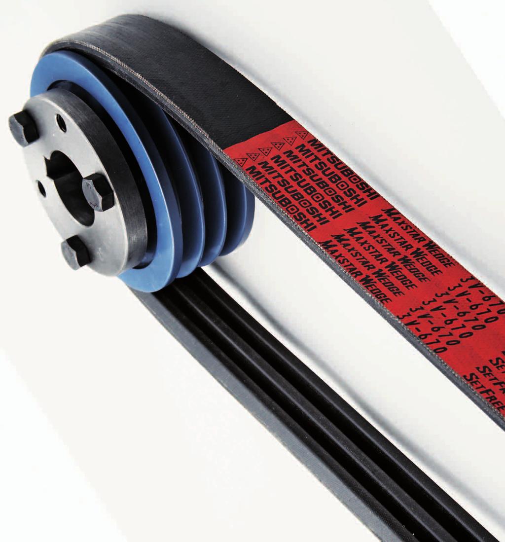
5 Product Classification 2 Classical V-Belts for DIN2215/ISO 4184 Maxstar Wedge V-Belts for RMA / MPTA Narrow V-Belts for DIN7753/ISO4184 Fig. 3 Fig. 4 Fig. 5 Classical V-Belt is most widely used power transmission belts. Economical and easily obtained for replacement. Sections: Wrapped Type ( Z / A / B / C / D / E ) Raw Edge Cogged Type ( ZX / AX / BX / CX ) Applications: Machine industry in general and agricultural machinery. Working temperature: -40~+70C (Wrapped Type), -30~+90C (Raw Edge Cogged Type) Electrically conductive according to ISO1813 Maxstar Wedge V-Belt for RMA / MPTA has double power transmission capacity of Classical V-belt for DIN due to an effect of the wedge. It features high-speed transmission of maximum 40m/sec. and an energy saving, compact design. Sections: Wrapped Type ( 3V / 5V / 8V ) Raw Edge Cogged Type ( 3VX / 5VX ) Applications: Machine industry in general, and partly agricultural machinery. Working temperature: Working temperature: -30~+90C Electrically conductive according to RMA IP3-3 Narrow V-belts for DIN enables space saving and high speed drive, and reduce operating and maintenance costs. And it features oil and heat resistant, static conductive properties. Sections: Wrapped Type ( SPZ / SPA / SPB / SPC ) Raw Edge Cogged Type ( SPZX / SPAX / SPBX / SPCX ) Applications: Machine industry in general, and partly agricultural machinery. Working temperature: Working temperature: -30~+90C Electrically conductive according to ISO Properties 3
6 2 Product Classification Double V-Belts Double V-belts are recommended for serpentine drives where the power must be transmitted by both the top and the bottom of the belt. Excellent fl exibility in both direction. Sections: ( AA / BB / CC ) Applications: Agricultural machinery and industrial drives. 1 Properties Perforated Open-End V-Belts Fig. 6 Perforated open-end V-belts are designed to operate with metal fasteners. These belts are recommended for temporary use or when installation of the standard V-belts is diffi cult. Sections: ( Z / A / B / C ) Applications: Industrial (light duty) drives with difficult installation. Conveyor systems. Fig. 7 4
7 Standard Range 3 MITSUBOSHI Classical V-Belts for DIN2215/ISO4184 Z/10, ZX 10 Belt indication Z 50 Table 1 6 Cross section Belt Code(inch) Belt Code Inner Li (mm) Datum Ld(mm) Z-Section Inner Belt Code Li (mm) Datum Ld(mm) Belt Code Inner Li (mm) Datum (Ld) according to ISO 4184 corresponds to the pitch (Lw) according to DIN : Available size for Raw Edge Cogged V-Belts ZX Datum Ld(mm) up to 93" Properties 5
8 3 Standard Range A/13, AX 13 Belt indication A 64 Table 2 9 Cross section Belt Code(inch) 1 Properties Belt Code Inner Li (mm) Datum Ld(mm) Belt Code Inner Li (mm) Datum (Ld) according to ISO 4184 corresponds to the pitch (Lw) according to DIN : Available size for Raw Edge Cogged V-Belts AX A-Section Datum Belt Code Ld(mm) Inner Li (mm) Datum Ld(mm) Belt Code Inner Li (mm) Datum Ld(mm) up to 360"
9 Standard Range 3 B/17, BX 17 Belt indication B 59 Table 3 11 Cross section Belt Code(inch) Belt Code Inner Li (mm) Datum Ld(mm) Belt Code Inner Li (mm) Datum Ld(mm) Datum (Ld) according to ISO 4184 corresponds to the pitch (Lw) according to DIN : Available size for Raw Edge Cogged V-Belts BX Belt Code B-Section Inner Li (mm) Datum Ld(mm) Belt Code Inner Li (mm) Datum Ld(mm) Belt Code Inner Li (mm) Datum Ld(mm) up to 660" Properties 7
10 3 Standard Range C/22, CX 22 Belt indication C 93 Table 4 14 Cross section Belt Code(inch) 1 Properties Belt Code Inner Li (mm) Datum Ld(mm) Belt Code Inner Li (mm) C-Section Datum Belt Code Ld(mm) Inner Li (mm) Datum Ld(mm) Belt Code Inner Li (mm) Datum Ld(mm) up to 660" Datum (Ld) according to ISO 4184 corresponds to the pitch (Lw) according to DIN : Available size for Raw Edge Cogged V-Belts CX 8
11 Standard Range 3 Table 5 D/32 E/40 Belt indication Belt indication D 120 E Cross section Belt Code(inch) 25 Cross section Belt Code(inch) Belt Code Inner Li (mm) Datum Ld(mm) Belt Code D-Section Inner Li (mm) Datum Ld(mm) Belt Code Inner Li (mm) Datum Ld(mm) Belt Code Inner Li (mm) E-Section Datum Ld(mm) Belt Code Inner Li (mm) Datum Ld(mm) Datum (Ld) according to ISO 4184 corresponds to the pitch (Lw) according to DIN Properties 9
12 3 Standard Range Cross section Dimension of Classical V-belts for DIN Table 6 Section ISO 4184 DIN 2215 Z 10 A 13 B 17 C 22 D 32 E 40 Top belt width bo (mm) Datum width bd (mm) Height of belt h (mm) Properties Datum Ld Li+ (mm) Distance down to datum line hd (mm) Outer La Li+ (mm) Recommended minimum Pulley datum diameter dd (mm) 45 (40) 71 (63) 112 (90) 180 (140) Recommended maximum Belt speed V (m/s) 30 ( ) : Figure of recommended minimum Pulley datum diameter for Raw Edge Cogged type. bo bd hd h Fig. 8 10
13 Standard Range 3 Maxstar Wedge V-belts for RMA / MPTA Table 7 h bo Section bo (mm) h (mm) 3V/9N (3VX) V/15N (5VX) V/25N Belt indication 5V 1000 Cross section Belt Code(inch 10) 3V(3VX)-Section 5V(5VX)-Section 8V-Section Belt Code Outer La(mm) Belt Code Outer La(mm) Belt Code Outer La(mm) Properties : Available size for Maxstar Wedge Raw Edge Cogged V-Belts 3VX & 5VX 11
14 12 3 Standard Range Narrow V-belts for DIN7753 / ISO4184 SPZ(SPZX)-Section SPA(SPAX)-Section SPB(SPBX)-Section SPC(SPCX)-Section Datum Ld(mm) Outer La(mm) Datum Ld(mm) Outer La(mm) Datum Ld(mm) Outer La(mm) Datum Ld(mm) Outer La(mm) Datum Ld(mm) Outer La(mm) Datum Ld(mm) Outer La(mm) Datum Ld(mm) Outer La(mm) Table 8 : Available size for Narrow Raw Edge Cogged V-Belts SPZX, SPAX, SPBX, SPCX Datum (Ld) according to ISO 4184 corresponds to the pitch (Lw) according to DIN Section bo (mm) h (mm) SPZ (SPZX) SPA (SPAX) SPB (SPBX) SPC (SPCX) Belt indication SPZ 1000 Cross section Datum (mm) bo h up to up to Properties
15 Standard Range 3 Cross section Dimension of Narrow V-belts for DIN & Maxstar Wedge V-belts for RMA / MPTA Section SPZ SPA SPB SPC 3V 5V 8V Table 9 Top belt width bo (mm) Datum width bd (mm) Height of belt h (mm) Inner Li Ld- (mm) Outer La Ld+ (mm) Distance down to datum line hd (mm) Properties Recommended minimum Pulley datum diameter dd (mm) 63 (56) 90 (71) 140 (112) 224 (180) 63 (56) 140 (112) 335 Recommended maximum Belt speed V [m/s] 42 ( ) : Recommended minimum Pulley datum diameter for Raw Edge Cogged type. bo bd hd h Fig. 9 13

16 3 Standard Range Double V-belts for DIN7722 / ISO5289 b h Table 10 Dimension of Double V-Belts (mm) Section b h 1 2 Minimum Recommended Pulley diameter A B C Fig Properties AA Cross Section BB Cross Section CC Cross Section Belt Code AA 51 AA 55 AA 60 AA 62 AA 64 AA 66 AA 68 AA 70 AA 75 AA 80 AA 85 AA 90 AA 92 AA 96 AA 105 AA 112 AA 120 AA 128 Fig. 11 Table 11 Table 12 Table 13 Pitch Pitch Pitch Belt Code Belt Code inch mm inch mm inch mm BB 43 BB 45 BB 51 BB 53 BB 54 BB 55 BB 60 BB 68 BB 71 BB 72 BB 73 BB 74 BB 75 BB 76 BB 77 BB 81 BB 83 BB 85 BB 90 BB 92 BB 93 BB 94 BB 96 BB 97 BB 103 BB 105 BB 107 BB 108 BB 111 BB 112 BB 116 BB 117 BB 118 BB 120 BB 123 BB 124 BB 128 BB 129 BB 130 BB 136 BB 140 BB 144 BB 155 BB 157 BB 158 BB 162 BB 168 BB 169 BB 173 BB 180 BB 182 BB 190 BB 195 BB 210 BB 225 BB 226 BB 228 BB 230 BB 240 BB 255 BB 267 BB 270 BB 273 BB 277 BB 278 BB 285 BB CC 81 CC 85 CC 90 CC 96 CC 105 CC 112 CC 119 CC 120 CC 125 CC 128 CC 136 CC 144 CC 148 CC 158 CC 162 CC 173 CC 180 CC 195 CC 210 CC 225 CC 240 CC 255 CC 270 CC 300 CC 330 CC 360 CC 390 CC
 10.")
 40 40 40 40 Length per roll ( m ) 100 100 100 100 Hole diameter (mm)")
17 Standard Range 3 Perforated Open-End V-belts Fig. 13 b h Fig. 12 Dimension of Perforated Open-End V-belts Table 14 Section Z A B C b (mm) h (mm) Angle ( ) Length per roll ( m ) Hole diameter (mm) Hole pitch (mm) Properties 15
18 4 V-belt Pulleys Pulley for Classical V-belts for DIN & Narrow V-belts for DIN Pulley for Classical V-belts & Narrow V-belts complies with DIN standard 2217 Part 1. Fig. 14 single-groove multi-groove break sharp corners Rz100 t f b1 bw f dw c f b2 e 1 Properties Rz100 Rz100 Dimensions (mm) Table 15 Belt section to DIN DIN symbol ISO symbol Z(ZX) A(AX) B(BX) C(CX) D E Belt section to DIN DIN symbol SPZ SPA SPB SPC 7753 part 1 ISO symbol SPZ(SPZX) SPA(SPAX) SPB(SPBX) SPC(SPCX) Pitch width bw Upper groove width b c Groove spacing e f 12 ± ± 0.6 Groove depth t > ± ± > ± ± > ± ± > ± ± > ± ± Tolerance for ± 1 ± 1 ± 1 ± 30' ± 30' ± 30' > 630 Pulley face width b2 for number of grooves n b2=(n-1) e+2 f ) bw corresponds to Datum width bd. 2) dw corresponds to Datum diameter dd
19 V-belt Pulleys 4 Pulley for Maxstar Wedge V-belts for RMA / MPTA Fig. 15 e f b1 g bw r1 r1 a t Dimensions (mm) dp de Table 16 1 Properties Belt section Effective diameter: de ( ) Effective width b1 Pitch width bw a Groove depth min. t Pitch e Groove spacing:f g 3V (3VX) < de < de 300 > ± ± ± ± ± ± V (5VX) < de 400 > ± ± ± ± ± V < de 560 > ± ± ± ± ± Number of belts & pulley width Number of Belt belts Section Table V V V
20 5 Calculation of V-belt drives design Abbreviations used in Formulas Symbol Unit Term Pt kw Power to be transmitted Pd kw Design power Ks Service factor Ko Service correction factor Ki Idler correction factor Ke Environment correction factor Pr kw Power rating Ps kw Basic power rating Pa kw Additional power rating for speed ratio Pc kw Correction power rating K Belt correction factor K Arc of contact correction factor Kc Power rating correction factor La mm Outer Ld mm Datum Li mm Inner D mm Large pulley d mm Small pulley Do, do mm/m Pulley outside diameter Dd, dd mm/m Pulley datum diameter Id mm Idler pulley diameter C mm Center distance C' mm Tentative center distance To N Minimum static tension Tp N Static tension Ti N Installation tension Tt N Tight side tension Ts N Slack side tension Te N Effective tension Tmax N Maximum drive tension Ta N Allowable tension TR Tension ratio F N Shaft load Fs N Static shaft load Ls mm Span F N Deflection load mm Deflection (deg.) Arc of contact Coefficient of friction ' Apparent coefficient of friction ro mm Ride out nd rpm Small pulley speed nd rpm Large pulley speed SR Speed ratio V m/sec. Belt speed W kg/m Belt weight per unit Ld' mm Tentative datum nb Number of belts Tq Nm Torque n rpm Pulley speed g 9.8m/sec. 2 Gravity acceleration Table 18 18
21 Calculation of V-belt drives design 5 Formulas for V-belt drives design Item Formula Term Design power Pd = Pt Ks Pd : Design Power (kw) Pt : Power to be transmitted (kw) Ks : Service factor Ks : Service factor Ko : Service correction factor Service factor Ks = Ko + Ki + Ke Ki : Idler correction factor Ke : Environment correction factor Pr : Power rating (kw) Power rating Pr = Ps + Pa Ps : Basic power rating (kw) Pa : Additional power rating for speed ratio (kw) Pc : Correction power rating (kw) Pr : Power rating (kw) Correction power rating Pc = Pr K K K : Belt correction factor K : Arc of contact correction factor SR: Speed ratio Speed ratio nd : Small pulley speed nd Dd SR = = nd : Large pulley speed nd dd Dd : Large pulley datum diameter (mm) dd : Small pulley datum diameter (mm) Ld' : Tentative datum (mm) C' : Tentative center distance (mm) Tentative datum Ld' = 2C' (Dd + dd) Dd : Large pulley datum diameter (mm) dd : Small pulley datum diameter (mm) Dd : Large pulley datum diameter (mm) Datum dd : Small pulley datum diameter (mm) (Dd + dd) (Dd dd) 2 Ld = 2C + + C : Center distance (mm) 2 4C : Ld : Datum (mm) Center distance C : Center distance (mm) b + b 2 8 (Dd dd) 2 : C = 8 Dd : Large pulley datum diameter (mm) dd : Small pulley datum diameter (mm) b = 2Ld (Dd + dd) Ld : Datum (mm) : Arc of contact for small pulley ( ) 57.3(Dd dd) Dd : Large pulley datum diameter (mm) Arc of contact = 180 dd : Small pulley datum diameter (mm) C C : Center distance (mm) Number of belts nb = Pd nb : Number of belts Pd : Design power (kw) Pc Pc : Correction power rating (kw) Belt Speed Power to be transmitted Power to be transmitted Effective tension Effective tension Torque Tight side tension Slack side tension Tension ratio Minimum static tension Static shaft load Span V = Pt = Pt = Te = Te = Te V 1,000 Tq n Tq dd Tq = Te 1,000 Pt V dd 2 = dd nd ,000 Pd 2.5 Tt = + W V 2 nb V 2 K 1,000 Pd K Ts = + W V 2 nb V 2 K TR = Tt Ts To = 0.9{ 500 (2.5 K )Pd + W } K nb V V2 Fs = 1.5 (2nb To sin ) 2 Ls = dd nd 60 1,000 (Dd dd) 2 C 2 4 V : Belt speed (m/sec) dd : Small pulley datum diameter (mm) nd : Small pulley speed (rpm) Pt : Power to be transmitted (kw) Te : Effective tension (N) V : Belt speed (m/sec) Pt : Power to be transmitted (kw) Tq : Torque (Nm) n : Pulley speed (rpm) Te : Effective tension (N) Tq : Torque (Nm) dd : Pulley datum diameter (m) Te : Effective tension (N) Pt : Power to be transmitted (kw) V : Belt speed (m/sec) Tq : Torque (Nm) Te : Effective tension (N) dd : Pulley datum diameter (m) Tt : Tight side tension (N) Pd : Design power (kw) nb : Number of belts V : Belt speed (m/sec) Ts : Slack side tension (N) Pd : Design power (kw) nb : Number of belts V : Belt speed (m/sec) TR : Tension ratio Tt : Tight side tension (N) Ts : Slack side tension (N) To : Minimum static tension (N) K : Arc of contact correction factor Pd : Design power (kw) nb : Number of belts Fs : Static shaft load (N) nb : Number of belts To : Minimum static tension (N) : Arc of contact for small pulley ( ) Ls : Span (mm) C : Center distance (mm) Dd : Large pulley datum diameter (mm) dd : Small pulley datum diameter (mm) Table 19 K : Arc of contact correction factor W : Belt weight per unit (kg/m) K : Arc of contact correction factor W : Belt weight per unit (kg/m) W : Belt weight per unit (kg/m) V : Belt speed (m/sec) 19
22 5 Calculation of V-belt drives design Basic Power Rating (Ps) Table 20 Z/10-Section [kw] small pulley speed nd(rpm) Small pulley datum diameter dd (mm) Additional power rating for speed ratio (Pa) to to to 1.57< Belt speed is over 30 m/sec to 35 m/sec. Please consult our sales company or Engineering Department. Belt speed is over 35 m/sec to 40 m/sec. Please consult our sales company or Engineering Department. 20
23 Calculation of V-belt drives design 5 Basic Power Rating (Ps) Table 21 ZX-Section [kw] small Small pulley datum diameter dd (mm) Additional power rating for speed ratio (Pa) pulley speed nd(rpm) to to to < Belt speed is over 30 m/sec to 35 m/sec. Please consult our sales company or Engineering Department. Belt speed is over 35 m/sec to 40 m/sec. Please consult our sales company or Engineering Department. 21
24 5 Calculation of V-belt drives design Table 22 A/13-Section [kw] small pulley speed nd(rpm) Basic Power Rating (Ps) Small pulley datum diameter dd (mm) Additional power rating for speed ratio (Pa) to to to 1.57< Belt speed is over 30 m/sec to 35 m/sec. Please consult our sales company or Engineering Department. Belt speed is over 35 m/sec to 40 m/sec. Please consult our sales company or Engineering Department. 22
25 Calculation of V-belt drives design 5 Table 23 AX-Section [kw] small Small pulley datum diameter dd (mm) Additional power rating for speed ratio (Pa) pulley speed nd(rpm) to to to < Basic Power Rating (Ps) Belt speed is over 30 m/sec to 35 m/sec. Please consult our sales company or Engineering Department. Belt speed is over 35 m/sec to 40 m/sec. Please consult our sales company or Engineering Department. 23
26 5 Calculation of V-belt drives design Table 24 B/17-Section [kw] small pulley speed nd(rpm) Basic Power Rating (Ps) Small pulley datum diameter dd (mm) Additional power rating for speed ratio (Pa) to to to 1.57< Belt speed is over 30 m/sec to 35 m/sec. Please consult our sales company or Engineering Department. Belt speed is over 35 m/sec to 40 m/sec. Please consult our sales company or Engineering Department
27 Calculation of V-belt drives design 5 Table 25 BX-Section [kw] small Small pulley datum diameter dd (mm) Additional power rating for speed ratio (Pa) pulley speed nd(rpm) to to to < Basic Power Rating (Ps) Belt speed is over 30 m/sec to 35 m/sec. Please consult our sales company or Engineering Department. Belt speed is over 35 m/sec to 40 m/sec. Please consult our sales company or Engineering Department
28 5 Calculation of V-belt drives design Table 26 C/22-Section [kw] small pulley speed nd(rpm) Basic Power Rating (Ps) Small pulley datum diameter dd (mm) Additional power rating for speed ratio (Pa) to to to 1.57< Belt speed is over 30 m/sec to 35 m/sec. Please consult our sales company or Engineering Department. Belt speed is over 35 m/sec to 40 m/sec. Please consult our sales company or Engineering Department. 26
29 Calculation of V-belt drives design 5 Basic Power Rating (Ps) Table 27 CX-Section [kw] small Small pulley datum diameter dd (mm) Additional power rating for speed ratio (Pa) pulley speed nd(rpm) to to to < Belt speed is over 30 m/sec to 35 m/sec. Please consult our sales company or Engineering Department. Belt speed is over 35 m/sec to 40 m/sec. Please consult our sales company or Engineering Department. 27
30 5 Calculation of V-belt drives design Basic Power Rating (Ps) Table 28 D/32-Section [kw] small pulley speed nd(rpm) Small pulley datum diameter dd (mm) Additional power rating for speed ratio (Pa) to to to 1.57< Belt speed is over 30 m/sec to 35 m/sec. Please consult our sales company or Engineering Department. Belt speed is over 35 m/sec to 40 m/sec. Please consult our sales company or Engineering Department. 28
31 Calculation of V-belt drives design 5 Table 29 E/40-Section [kw] small pulley speed nd(rpm) Basic Power Rating (Ps) Small pulley datum diameter dd (mm) Additional power rating for speed ratio (Pa) to to to 1.57< Belt speed is over 30 m/sec to 35 m/sec. Please consult our sales company or Engineering Department. Belt speed is over 35 m/sec to 40 m/sec. Please consult our sales company or Engineering Department. 29
32 5 Calculation of V-belt drives design Basic Power Rating (Ps) Table 30 SPZ-Section [kw] small Small pulley datum diameter dd (mm) Additional power rating for speed ratio (Pa) pulley speed nd(rpm) to to to < Belt speed is over 30 m/sec to 35 m/sec. Please consult our sales company or Engineering Department. Belt speed is over 35 m/sec to 40 m/sec. Please consult our sales company or Engineering Department. 30
33 Calculation of V-belt drives design 5 Basic Power Rating (Ps) Table 31 SPZX(3VX)-Section [kw] small pulley speed nd(rpm) Small pulley datum diameter dd (mm) Additional power rating for speed ratio (Pa) to to to 1.57< Belt speed is over 30 m/sec to 35 m/sec. Please consult our sales company or Engineering Department. Belt speed is over 35 m/sec to 40 m/sec. Please consult our sales company or Engineering Department. Note:Pulley diameters shown are outside diameters for section 3VX 31
34 5 Calculation of V-belt drives design Basic Power Rating (Ps) Table 32 SPA-Section [kw] small Small pulley datum diameter dd (mm) Additional power rating for speed ratio (Pa) pulley speed nd(rpm) to to to < Belt speed is over 30 m/sec to 35 m/sec. Please consult our sales company or Engineering Department. Belt speed is over 35 m/sec to 40 m/sec. Please consult our sales company or Engineering Department. 32
35 Calculation of V-belt drives design 5 Basic Power Rating (Ps) Table 33 SPAX-Section [kw] small pulley speed nd(rpm) Small pulley datum diameter dd (mm) Additional power rating for speed ratio (Pa) to to to 1.57< Belt speed is over 30 m/sec to 35 m/sec. Please consult our sales company or Engineering Department. Belt speed is over 35 m/sec to 40 m/sec. Please consult our sales company or Engineering Department. 33
36 5 Calculation of V-belt drives design Table 34 SPB-Section [kw] small Small pulley datum diameter dd (mm) Additional power rating for speed ratio (Pa) pulley speed nd(rpm) to to to < Basic Power Rating (Ps) Belt speed is over 30 m/sec to 35 m/sec. Please consult our sales company or Engineering Department. Belt speed is over 35 m/sec to 40 m/sec. Please consult our sales company or Engineering Department. 34
37 Calculation of V-belt drives design 5 Table 35 SPBX(5VX)-Section [kw] small pulley speed nd(rpm) Basic Power Rating (Ps) Small pulley datum diameter dd (mm) Additional power rating for speed ratio (Pa) to to to 1.57< Belt speed is over 30 m/sec to 35 m/sec. Please consult our sales company or Engineering Department. Belt speed is over 35 m/sec to 40 m/sec. Please consult our sales company or Engineering Department. 35
38 5 Calculation of V-belt drives design Basic Power Rating (Ps) Table 36 SPC-Section [kw] small Small pulley datum diameter dd (mm) Additional power rating for speed ratio (Pa) pulley speed nd(rpm) to to to < Belt speed is over 30 m/sec to 35 m/sec. Please consult our sales company or Engineering Department. Belt speed is over 35 m/sec to 40 m/sec. Please consult our sales company or Engineering Department. 36
39 Calculation of V-belt drives design 5 Basic Power Rating (Ps) Table 37 SPCX-Section [kw] small pulley speed nd(rpm) Small pulley datum diameter dd (mm) Additional power rating for speed ratio (Pa) to to to 1.57< Belt speed is over 30 m/sec to 35 m/sec. Please consult our sales company or Engineering Department. Belt speed is over 35 m/sec to 40 m/sec. Please consult our sales company or Engineering Department. 37
40 5 Calculation of V-belt drives design Basic Power Rating (Ps) Table 38 3V-Section [kw] small Small pulley effective diameter de (mm) Additional power rating for speed ratio (Pa) pulley speed nd(rpm) to to to < Belt speed is over 30 m/sec to 35 m/sec. Please consult our sales company or Engineering Department. Belt speed is over 35 m/sec to 40 m/sec. Please consult our sales company or Engineering Department. 38
41 Calculation of V-belt drives design 5 Table 39 small pulley speed nd(rpm) Basic Power Rating (Ps) 5V-Section Small pulley effective diameter de (mm) Additional power rating for speed ratio (Pa) to to to 1.57< Belt speed is over 30 m/sec to 35 m/sec. Please consult our sales company or Engineering Department. Belt speed is over 35 m/sec to 40 m/sec. Please consult our sales company or Engineering Department. 39
42 5 Calculation of V-belt drives design Table 40 8V-Section [kw] small Small pulley effective diameter de (mm) Additional power rating for speed ratio (Pa) pulley speed nd(rpm) to to to < Basic Power Rating (Ps) Belt speed is over 30 m/sec to 35 m/sec. Please consult our sales company or Engineering Department. Belt speed is over 35 m/sec to 40 m/sec. Please consult our sales company or Engineering Department
43 Calculation of V-belt drives design 5 Service correction factor (Ko) Service correction factor (Ko) takes into account the daily operating period and the type of driving units and driven machines. The driven machines are representative samples only. Select a driven machine whose load characteristics most appropriate those of the machine being considered. Service correction factor (Ko) Driven Machine Agitators for liquids. Small centrifugal blowers. Fans up to 7.5 kw. Light-duty conveyors. Belt conveyors for sand, grain, etc. Dough mixers. Fans over 7.5 kw. Generators. Machine tools. Punching, pressing and shearing machines. Printing machines. Positive displacement rotary pumps, Vibrating and rotary screens. AC motors, single-and three-phase with star-delta start. DC shunt-wound motors, Multiple cylinder internal combustion engines. Number of operating hours per day Up to 10 Over 10 to 16 Driving unit / Motor Over 16 AC motors, single and three-phase, series wound, slip-ring motors with direct start. DC motors, series and compound wound. Single cylinder internal combustion engines. Number of operating hours per day Up to 10 Over 10 to 16 Table 41 Over Brick-making machinery. Bucket elevator. Piston compressors. Screw conveyors. Hammer mills. Hollanders. Piston pumps. Positive displacement blowers. Crushers. Woodworking machinery. Textile machinery Gyratory and jaw-roll crushers. Mills (ball/rod). Hoists (heavy loads). Rolling mills, calenders etc, for the rubber and plastics industries Idler correction factor (Ki) Idler correction factor (Ki) Table 42 Location of Idler Belt slack side, inside of belt Belt slack side, outside of belt Belt tight side, inside of belt Belt tight side, outside of belt Correction factor
44 5 Calculation of V-belt drives design Arc of contact correction factor (K ) Basic power rating (Ps) is based on a 180 Arc of contact for smaller pulley. If Arc of contact is smaller, the power transmission capability is reduced and Ps is corrected by multiplying the read table value by factor K. Arc of contact correction factor (K ) Dd-dd C Arc of contact for small pulley degree ( ) Arc of contact correction factor (K ) Table 43 42
45 Calculation of V-belt drives design 5 Belt correction factor (K ) The belt corrction factor (K ) expresses the defl ection frequency which the V-belt is to when passing over the pulleys. The basic power rating (Ps) per belt are based on the basic belt. When the belt differs from that, the deflection frequency and belt correction factor are changed into K =1.00. Basic Datum Table 44 Cross section Z A B C D E SPZ SPZX SPA SPAX SPB SPBX SPC SPCX Basic Datum Ld(mm) Cross section 3V 3VX 5V 5VX 8V Outer La (mm) Belt correction factor (K ) for Classical V-belts for DIN & Narrow V-belts for DIN. Datum Ld (mm) Z ZX A AX B BX C CX D 0.82 K E SPZ SPZX SPA SPAX SPB SPBX SPC SPCX Datum Ld (mm) Z ZX A AX B BX C CX D K E SPZ SPZX SPA SPAX Table 45 SPB SPBX SPC SPCX
46 5 Calculation of V-belt drives design Belt correction factor (K ) for Maxstar Wedge V-belts for RMA / MPTA Table 46 Outer La (mm) 3V 3VX K 5V 5VX 8V Outer La (mm) 3V 3VX K 5V 5VX 8V
47 Calculation of V-belt drives design 5 Installation and take-up allowance To install the belts without damaging them and to maintain the proper belt tension, it must be possible to adjust Center distance as specifi ed in table 47. If Center distance is fixed, an adjustment facility can be made by means of tension idler. Allowance for Installation y Fig. 16 Center Distance Allowance for Take-up x Minimum allowance x/y for adjusting drive center distance Table 47 Minimum adjust y [mm] Minimum take-up [mm] Datum Ld [mm] SPZ SPZX 3V A/13 AX 3VX SPA SPAX SPB 5V SPBX 5VX SPC SPCX Z/10 ZX B/17 BX C/22 CX D/32 E/40 8V All sections <
48 5 Calculation of V-belt drives design Cross section selection chart for V-belts On the bottom line of Fig.17 ~ 21 is located the design power, then read up to speed of small pulley (rpm). You will find the correct cross section for the drive. When Design power and Small pulley speed lines intersect at, or near, one of the diagonals separating two cross section areas, it is always advisable to investigate the possibility of using the smaller cross section, as this is usually more economical. Cross section selection chart for Classical V-belts for DIN 5000 Fig Small pulley speed (rpm) Z / 10 A / 13 B / 17 C / 22 D / 32 E / Design power [kw] Small pulley speed (rpm) Cross section selection chart for Classical Raw Edge Cogged V-belts ZX AX BX Design power [kw] CX Fig
49 Calculation of V-belt drives design Cross section selection chart for Maxstar Wedge V-belts for RMA / MPTA Fig Small pulley speed (rpm) V / 9N 3VX 5V / 15N 5VX 8V / 25N Design power [kw] Cross section selection chart for Narrow V-belts for DIN Fig. 20 Small pulley speed (rpm) SPZ SPZX SPA SPAX SPB SPBX SPC SPCX Design power [kw] 47
50 5 Calculation of V-belt drives design Calculation example Classical V-belts for DIN Example : Machine : Compressor Prime mover : Normal torque motor 3.7 kw/1r.p.m Operating hours : 8hrs. / day Center distance C : About 300mm Speed ratio SR : 2.0 Step 1. Calculate Design power (Pd) Pd = Pt Ks Pd = = 4.8 kw Ko : See table 41 on page 41 ( Ki = 0, Ko = 1.3) ( Ks = Ko + Ki) Step 2. Select the proper V-belt section See fi g.17 on page 46 A-section Step 3. Choose Pulleys datum diameter SR = nd = Dd When choosing dd = 71mm Dd = dd SR nd dd Dd = 71 2 = 142mm Step 4. Determine the V-belt & Center distance Tentative datum Ld' Ld' = 2C' (Dd+dd) Ld' = (142+71) = mm Nearest Standard datum selected in table 2 on page (A35.5) Center distance C C = b + b ² 8 (Dd dd)² b 8 = ( ) = mm b = 2Ld-3.14(Dd + dd) C = ( ) ² 8 (142 71)² = =296mm Step 5. Number of belts nb = Pd Pd = Pc (Ps + Pa) (K K ) Pc = (Ps + Pa) (Kc) Kc = K K K : = 0.24 ( K = 0.97) 296 Kc = = 0.84 Pc = ( ) 0.84 = 1.03kw Ps = See table 22 on page 22 Pa = See table 22 on page 22 Arc of contact correction factor (K ) Dd - dd and C see table 43 on page 42 K = See table 45 on page 43 nb = 3.7 = pcs. 48
51 Calculation of V-belt drives design 5 Calculation example Maxstar Wedge V-belts for RMA / MPTA Example : Gasoline engine 45kw/1200rpm Driven machine : Generator 800rpm Service condition : Approximate Center distance 1500mm : Small pulley effective diameter = 315mm : Daily operating 8hr/day Step 1. Calculate Design power (Pd) Pd = Pt Ks Ko : See table 41 or page 41 ( Ks = Ko + Ki ) Pd = = 54 kw ( Ki = 0, Ko = 1.2 ) Step 2. Select the proper Maxstar Wedge V-belts for RMA / MPTA section See fi g.19 on page 47 Step 3. Calculate Speed ratio (SR) nd Dp 1200 SR = = SR = = 1.5 nd dp 800 Step 4. Determine Large pulley effective diameter (De) Under the above condition, de = 315 De = de 1.5 Step 5. Calculate Belt speed (V) de nd V = V = = 19.8 m /sec Step 6. Effective Ld' Le' = 2C' (De + de) Belt section : 5V De = = 472.5mm Le' = ( ) = mm Nearest standard Effective selected in table 7 on page 11. Le = 4310mm (5V1) Step 7. Center distance C C = b + b 2 8 (De de) 2 8 b = 2Le 3.14 (De + de) b = ( ) = mm ( ) C = 2 8 ( ) 8 = 1535mm 2 Step 8. Number of belts nb = Pd /Pc = Pd / (Ps + Pa) (K K ) Pc = (Ps + Pa) Kc Kc = K K 54 nb = = belts 23.7 Pc = ( ) 1.04 = 23.7kw Kc = = 1.04 Ps = See table 39 on page 39 Pa = See table 39 on page 39 Arc of contact correction factor (K ) Ps = Pa = 0.91 K = 0.99 De de (De de) ( ) and = = C C 1535 see table 43 on page 42 Belt correction factor (K ) K = 1.05 see table 46 on page 44 49
52 5 Calculation of V-belt drives design Calculation example Narrow V-belts for DIN Example : Gasoline engine 60kw/1000rpm Driven machine : Generator 667rpm Service condition : Approximate Center distance 900mm : Large pulley datum diameter 375mm : Daily operating 8hr/day Step 1. Find Service correction factor (Ko) See table41 on page 41 Step 2. Calculate Design power (Pd) Pd = Pt Ks ( Ks = Ko + Ki ) Step 3. Select the proper Narrow V-belt section See fi g.20 on page 47 Ko = 1.2 Pd = = 72 kw ( Ki = 0, Ko = 1.2 ) SPB section Step 4. Calculate Speed ratio (SR) nd Dd SR = = nd dd Step 5. Determine Small pulley datum diameter (dd) Under the above condition, Dd = Dd dd = dd = = 250mm 1.5 SR Step 6. Calculate Belt speed (V) dd nd V = V = / = 13.1 m /sec. < 40 m /sec Step 7. Datum (Ld') Ld' = 2C' (Dd + dd) SR = 1000 / 667 = 1.5 Ld' = ( ) = 2781mm Nearest standard Datum selected in table 8 on page 12. Ld = 2800mm Step 8. Center distance C C = b + b 2 8 (Dd dd) 2 8 b = 2Ld 3.14 (Dd + dd) Step 9. Number of belts Pd Pd nb = = Pc (Ps + Pa) (K K ) Pc = (Ps + Pa) Kc Kc = K K Ps = See table 34 on page 34 Pa = See table 34 on page 34 Arc of contact correction factor (K ) Dd dd and C see table 43 on page 42 Belt correction factor (K ) see table 45 on page 43 b = ( ) = C = (3637.5) 2 8 ( ) 2 8 = 907.2mm 72 nb = = belts Pc = ( ) 0.95 = 12.95kw Kc = = 0.95 Ps = Pa = 0.66 K = 0.99 ( ) / 907 = 0.14 K =
53 Calculation of V-belt drives design 5 Tensioning design V-belts Tension of the belts on a V-belt drive is usually not critical. A few simple rules about tensioning will satisfy most of your requirements. For your proper tensioning of V-belts, just follow these four steps. Step 1. After placing V-belts into the pulleys grooves, increase the distance between pulleys until V-belts are snug. Step 2. Measure the of the span for your drive. At the center of the span, apply Deflection load (F ) in Fig. 21 on page 53 with spring scale in a direction perpendicular to the span until the belt is deflected from the normal by amount equal to 1.6mm for every 100mm. Step 3. A few days are necessary for V-belts to seat into pulley grooves. The belt tension for a V-belt drive is the lowest at which the belts will not slip under the highest load condition. A bigger tension than force maximum will reduce the life of belts and bearings, and a less tension than force minimum, will cause slip. Step 4. During the normal operation, a V-belts will seat itself into pulley grooves, and will require periodic checks to maintain tension. The seating occurs more rapidly during the first hours of operation. It is necessary to keep the belts and pulley from any foreign material which may cause slip. If a V-belts slips, tighten it. Recommendable belt Defl ection load to get the proper tension is shown in table 49. But the ideal tension can be obtained as follows : 1. Calculate Span Ls= C 2 (Dd dd) 2 4 Ls : Span (mm) C : Center distance (mm) Dd : Large pulley datum diameter (mm) dd : Small pulley datum diameter (mm) 2. Calculate Minimum static tension (2.5 - K ) Pd To= {500 K nb V + WV 2 } 0.9 To : Minimum static tension (N / pc.) K : Arc of contact correction factor Pd : Design power (kw) Tomax(initial) : Maximum belt tension at initial fi tting (N/a belt) Tomax(retension) : Maximum belt tension at retensioning (N/a belt) Tomax(initial)= 1.5 To Tomax(retension)=1.3 To 3. Calculate Deflection load A) Multiple V-belts drivers : F min = To + Y F max(initial) = 1.5 To + Y F max(retension) = 1.3 To + Y 16 B) Single V-belts drivers : F min = To + Y(Ls/L) 16 nb : Number of belts W : Belt weight per unit (kg / m) see Table 48 in page 50 V : Belt speed (m/sec.) 1.5 To + Y(Ls/L) F max(initial) = To + Y(Ls/L) F max(retension) = 16 F : Defl ection load (N / a belt) Y : a constant see Table 48 in page 50 L : Belt (mm) Ls : Span (mm) 4. Calculate maximum Shaft load at initial fitting Fs = 2nb To sin 1.5 Fs : Static shaft load (N) 2 : Arc of contact for small pulley 51
54 5 Calculation of V-belt drives design Belt weight per unit (W) & Constant (Y) Table 48 Belt Section W(kg/m) Y(N/pc) Z A B C D E SPZ SPA SPB SPC V V V ZX AX BX CX SPZX SPAX SPBX SPCX VX VX
55 Calculation of V-belt drives design Tensioning of V-belts Step 1. Calculate Span Span means the between the belt contact points to the pulleys (Ls in Fig. 21). If the diameter of the drive pulley and the driven pulley are the same, it is the same with Center Distance. Fig. 21 Deflection measurement Span Length(Ls) Step 2. Calculate Deflection load by loading on the center of Span. Load on the center of Span at right angle to the belt with the equipment like a spring balance, then check the load. Deflection should be 1.6mm per 100mm of Span. For example, if Span is 500mm, Deflection should be 8mm. Step 3. Adjust the belt tension so that the load calculated by step 2. is between maximum and minimum Defl ection load in Table 49. Deflection load & Belt tension Belt section 10/Z 13/A 17/B 22/C 32/D 40/E SPZ/3V SPA SPB/5V SPC 8V 10/ZX 13/AX 17/BX 22/CX SPZX/3VX SPAX SPBX/5VX SPCX Table 49 Maximum tensioning conditions Minimum tensioning conditions Small pulley Initial fi tting Retension diameter (mm) Deflection load (N) Belt tension (N) Deflection load (N) Belt tension (N) Defl ection load (N) Belt tension (N) ~ ~ ~ ~ ~ ~ ~ ~ ~ ~ ~ ~ ~ ~ ~ ~ ~ ~ ~ ~ ~ ~ ~ ~ ~ ~ ~ ~ ~ ~ ~ ~ ~ ~ ~ ~ ~ ~ ~ ~ ~ ~ ~ ~ ~ ~ ~ ~ ~ ~ ~ ~ ~ ~ ~ ~ ~ Tension values must be calculated for the pulleys which are not included in the above table. PLEASE USE THIS DATA AS A REFERENCE. 53
56 Special belt drives Use of idlers Idlers shorten the belt life.use idlers only in the following cases. When the center distance cannot be adjusted. When the V-belt is used as a clutch When the belt span is too long and the belt vibrates When a longer arc of contact with pulleys is required When the belt tension is to be maintained during operation When the belt is required to avoid obstructions Use of inside idlers Inside idler Driven Driver Place a grooved idler on the slack side of the belt. It is preferable to use an idler on the inside of the layout, not the outside. The inside idler should be placed near the large pulley, otherwise the arc of contact becomes smaller and belt might slip. Use of backside idlers Backside idler Driven Driver The backside idlers shorten the belt life signifi cantly, and are not recommended. Use a fl at pulley as a backside idler and place it near the small pulley. The diameter of idler pulleys shall be larger than the diameter specifi ed in Table 50. Use the idler bigger than twice the size of the small pulley for Maxstar Wedge. Minimum pitch diameter of idler pulley Table 50 Section Inside idler(mm) Outside idler(mm) A B C D E
57 Special belt drives Quarter-Turn Drives Quarter-Turn Drives are drives where the driver and driven shafts are at right angles to each other. To design Quarter-Turn Drives, follow the steps given in "Calculation of V-belt drives design" section for designing an ordinary drive, keeping in mind the following special points: 1. Speed ratio should be 2.50 or less. 2. A standard V-belt should be chosen which will give a minimum Center distance of: Minimum C = 5.5(D+W)(mm) D = Large pulley outside diameter (mm) W= Width of Deep Grooved Pulley, from Table Aligning the drive Looking down on the drive, a line from the center of the vertical shaft should pass through the center of the face of the pulley on the horizontal shaft. The horizontal shaft should be at right angles to this line. See "Top View" in Fig. 23. Looking at the side of the drive, the center of the horizontal shaft should be raised a distance "Y", from Table 51 above the level line through the center of the face of the pulley on the vertical shaft. See "Side View" in Fig Direction of rotation The direction of rotation must be such that the Tight side of the drive will be on the bottom. See "Side View" in Fig Power rating for Quarter-Turn Drives should be 90% from it for ordinary drives. And Arc of contact correction factor (K ) may be taken as 1.00 on Quarter-Turn Drives. 6. Deep grooved pulleys should always be used on Quarter-Turn Drives using indivisual V-belts. Horizontal shaft Horizontal shaft Top View Side View Tight side Fig. 23 Vertical shaft Vertical shaft Table 51 Center distance (unit: mm) Dimension Y Width of Deep grooved pulley (W) No. of Grooves V-Belt Section A B C D E 3V 5V 8V Table 52 (unit: mm)
58 Special belt drives V-Flat pulley drives What V-Flat drive is to use a V-Grooved pulley and the other fl at pulley with regard to V-belt drive. This type of drive is used when it is desirable to change a fl at belt drive into a V-belt drive, because it is often most economical to retain the fl at pulley. Classical V-belts for DIN (Z,A,B,C,D) are suitable for the drive. The following prerequisites must be fulfi lled to ensure the operating reliability of V-belt drive: The small pulley must be a grooved pulley. Speed ratio must be SR 3. Belt speed must be V 25 m/sec. The pitch diameter of fl at pulley = Outside diameter Value of table 54 Relation between pulley diameter and Center distance must be fulfi lled the following formula Dp dp C 1.17 Dp : Pitch diameter of fl at pulley (mm) dp : Pitch diameter of V pulley (mm) C : Center distance (mm) Table 53 Arc of contact correction factor for V-belt drives 3 Reference Dp-dp C Contact of small pulley ( ) Correction factor Table 54 Difference between pulley pitch diameter and outside diameter Belt Section Z A B C D E Difference between pitch diameter and outside diameter (mm) K

59 Banded V-belts MITSUBOSHI MULTI (Banded) V-belt is made up of two or more standard V-belts connected together at the top as shown in the picture. No special pulleys are needed, as the individual belts have the same cross section and spacing as those which operate on standard pulleys. The top backing of Multi V-belts does not come in contact with the top of the pulleys, so each multiple belt produces the same wedge effect as a single belt. Tensioning procedures are the same as for individual belts. Fig. 24 Advantage of Multi (Banded) V-belts In most of the applications, V-belts can meet the drive requirements. However, under certain operating conditions, belt whipping or vibration may become a critical problem, causing belts ultimately to come off the drive possible causes include the following: 1) Load vibration occurs periodically either on the driver side or at the drive unit, e.g. internal combustion engine, air compressor or piston pump. 2) There is excessively large load vibration or shock load, e.g. hoist or press. 3) Long span. 4) Vertical shaft drives. Belt vibration occurs laterally, as well as vertically. Under these conditions single matched sets of belts will be out of alignment in entering the pulley and will be damaged turned over or thrown off the drive. Multi V-belts are recommended for use under these conditions as they can stand lateral stress, and belt vibration is virtually eliminated, resulting in longer belt life expectancy. How to select Multi V-belts 1) Size Designation The available sizes are as follows. Available range of Multi V-belts Table 55 Cross section Range of available size Center to center of pulley grooves(p) B, BX B60~B315 19mm C, CX C76~C mm D D90~D mm 3V, 3VX 3V600~3V mm 5V, 5VX 5V630~5V mm 8V 8V1000~8V mm SPB SPB2120~SPB mm SPC SPC2120~SPC mm Fig. 25 2) Number of ribs Multi V-belts are available in 2,3,4 and 5 ribs. They may be used in matched sets for drives requiring more than 5 belts, as shown in the following table. 3 Table 56 Reference Number of belts Recommended combination ,3 3,4 4,4 Number of belts Recommended combination 5,4 5,5 4,3,4 4,4,4 4,5,4 5,4,5 5,5,5 Number of belts Recommended combination 4,4,4,4 4,4,5,4 4,4,5,5 5,4,5,5 5,5,5,5 57
V601-C. Industrial Power Transmission Products Conveyor Belts Engineering Plastics. January, 2007
 V601C R T e c h n o l o g y N a t u r e S o c i e t y Industrial Power Transmission Products Conveyor Belts Engineering Plastics January, 2007 Safety Precautions Please read all the warnings! Please take
CONTENTS RIBBED BELTS
 CONTENTS V-BELTS & CUT EDGE BELTS Profile Index 1-3 Cross Sectional View 4 Product Range 5-7 Classical V-s 8-12 Wedge V-s 13-17 Narrow V-s 18-20 Hexagonal s 21-22 Banded s 23-28 Cut Edge Cogged s 29-32
BELTS BELTS V-BELTS SYNCHRONOUS BELTS IMPORTANT REMINDER
 IMPORTANT REMINDER When using ARAMID FIBER REINFORCED (KEVLAR) be sure NOT to tension at higher force than recommended for standard conventional construction belts. Specially designed sheaves may be required
WRAPPED MULTI RIB POWER TRANSMISSION BELTS RAW EDGE COGGED HARVESTER COMBINE
 WRAPPED MULTI RIB POWER TRANSMISSION BELTS RAW EDGE COGGED HARVESTER COMBINE Quality Accreditations American Petroleum Institute ISO 9001:2000 American Petroleum Institute accredited Licence No : 1B-0009
SIT rubber V-Belts drives
 SIT rubber V-Belts drives Power transmission is key part of an automatic machine, in terms of efficiency, reliability and durability. Only using quality components can such goals be obtained. SIT S.p.A.
Engineering Data Tensioner Arms idler Sprocket Sets Idler Roller Pulley Sets
 CHAIN & PULLEY TENSIONERS Engineering Data Tensioner Arms idler Sprocket Sets Idler Roller Pulley Sets ENGINEERING DATA TENSIONING TECHNOLOGY Chain & V-Belt Tensioning Roller chains are power transmission
SIT BANDED - Narrow (ISO) SPZ - SPA SPB - SPC XPZ - XPA XPB - XPC V-BELTS - BANDED ISO APPLICATIONS KEY FEATURES & BENEFITS BELT MATERIAL
 SPZ - SPA SPB - SPC XPZ - XPA XPB - XPC V-BELTS - BANDED ISO APPLICATIONS KEY FEATURES & BENEFITS BELT MATERIAL") SIT BANDED - Narrow (ISO) E MC SPZ - SPA SPB - SPC XPZ - XPA XPB - XPC APPLICATIONS For shock loads applications, ideal for pulsating loads, high capacity drives and for short-center, heavy-duty drives.
SIT BANDED - Narrow (ISO) E MC SPZ - SPA SPB - SPC XPZ - XPA XPB - XPC APPLICATIONS For shock loads applications, ideal for pulsating loads, high capacity drives and for short-center, heavy-duty drives.
Power Transfer Training Seminar
 Power Transfer Training Seminar Power Transmission Dayco Offers a Full Line of Power Transmission Belting. Product Constructions: Wrapped, Raw-Edge, Synchronous, Poly-Rib, Double Angle, Urethane, Specialty
Cog-Belt XT V-Belt. Energy efficient. Smoother running. Design flexibility. High performance EPDM construction: High HP ratings.
 Power-WedgePanther XT Energy efficient 1 Smoother running Design flexibility 2 High performance EPDM construction: 4 3 High HP ratings Longer belt life Oil and heat resistant Resists hardening and glazing
V-Belt Installation, Maintenance & Storage Installation
 V-Belt Installation, Maintenance & Storage Installation 1. Check pulleys for rust, oil, grease, dust, dirt and other foreign materials. Clean the pulleys. Foreign materials accelerate belt wear and dramatically
POWER TRANSMISSION BELT
 ADD: 1614 WHIRLAWAY CT, ALLEN, TEXAS, 75002, USA TEL: (800) 810 6176 FAX: (817) 290 0537 EMAIL: sales@rtekindustrial.com WEB: www.rtekindustrial.com 2015-2016 Brochure POWER TRANSMISSION BELT R-TEK INTERNATIONAL
TRANSMISSIONS. Mechanical Power Transmission
 TRANSMISSIONS Mechanical Power Transmission Dunlop BTL Ltd European Distribution Centre MPT House Brunswick Road Cobbs Wood Industrial Estate Ashford, Kent. UK TN23 1EL Contact us +44 (0)1233 663340 +44
Catalog POWER TRANSMISSION BELT R TEK INTERNATIONAL. 214 Martin Dr, Wylie, Texas, 75098, USA
 ADD: 214 MARTIN DR, WYLIE, TEXAS, 75098, USA TEL: +1 (817) 808 6335 FAX: +1 (817) 290 0537 EMAIL: info@rtekindustrial.com WEB: http://www. rtekindustrial.com 2009 2010 Catalog POWER TRANSMISSION BELT R
Raw Edge Molded Cog Classical V Belts & High Power Molded Cog Wedge Belts
 Raw Edge Molded Cog Classical V Belts & High Power Molded Cog Wedge Belts standards DIN 2215/DIN 7753 (Part 1) ISO 4184 BS 3790 ISO 4183 Protorque Raw Edge Molded Cog Classical V and High Power Wedge Belts
Product Information. *D&D Global is the international manufacturer and wholesale distributor of D & D Power Drive Belts
 Product Information *D&D Global is the international manufacturer and wholesale distributor of D & D Power Drive Belts General Information Our belts are scientifically engineered using the latest technology
V-BELTS Rubber V-belts
 V-BELTS Rubber V-belts INDEX Introduction to V-belts 3 Product range 6 Technical calculation 7 Belt selection charts 10 Calculation example 12 Belt tensioning 13 Length measuring and groove pulleys 14
PVBELTSHANDBOOK2 22/6/07 10:14 Página 3 M D
 M D M D 4 INDEX TABLE OF CONTENTS MEGADYNE PV BELTS MEGADYNE PV BELTS 6 BELT FEATURES 7 PV BELT STRUCTURE 7 BELT CROSS SECTIONS AND DIMENSIONS 8 STANDARD BELT & PULLEY RANGE 10 SYMBOLS, UNITS, TERMS 13
SKF Power transmission belts
 SKF Power transmission belts Contents Foreword.... 3 SKF the knowledge engineering company.... 4 1 V-belts Product features SKF Wrapped Wedge and SKF Wrapped Narrow Wedge Belts............... 8 SKF Xtra
CLASSICAL V-BELTS (A B C D)
") Superior belt strength Excellent resistance to abrasion Greater grip for controlled slippage Classical V-belts remain the most widely used V-belt in the industry HEV branded V-belts have: CLASSICAL V-BELTS
Superior belt strength Excellent resistance to abrasion Greater grip for controlled slippage Classical V-belts remain the most widely used V-belt in the industry HEV branded V-belts have: CLASSICAL V-BELTS
Power Transmission Belt Drive System Installation, Maintenance and Troubleshooting Guide
 Power Transmission Drive System Installation, Maintenance and Troubleshooting Guide www.contitech.us Table of Contents Installation Guide 2 Table of Contents Installation V-s V-s 3 Banded s Torque Team
FRICTIon DRIVES. CRE Plus cogged raw edge belt. Classic V belt. Power Plus wrapped wedge belt. SynChRonouS DRIVES Classical
 FRICTIon DRIVES Classic V belt Power Plus wrapped wedge belt CRE Plus cogged raw edge belt Ideal for high ratio or small pulley drives, the Fenner Classic V belt has a specially treated jacket to give
3 ISO RoHS 3 Reach
 3 ISO 9001 3 RoHS 3 Reach POWER Classical V-Belts The conventional V Belts are produced with top-quality material and submitted to rigorous controls that guarantee elevated duration and resistance to oils,
index Megadyne PV-belts 2 Belt features and structure 3 Belt cross sections and dimensions 4 Pulleys 5 Standard belt range 6 Symbols, units, terms 8
 pv-belts index Megadyne PV-belts 2 Belt features and structure 3 Belt cross sections and dimensions 4 Pulleys 5 Standard belt range 6 Symbols, units, terms 8 Drive calculation procedure 9 Table 8: performance
60 Drive Design & Maintenance Manual FRICTION BELT DRIVES. Max. Bore Pulley F J K L M N Outside Code Dia (P) Grooves No. Metric Inch Type Dia (O)
 Grooves No. Metric Inch Type Dia (O)") Catalogue Pitch No. of Bush Max. Bore Pulley F J K L M N Outside Code Dia (P) Grooves No. Metric Inch Type Dia (O) 031Z0041 56 1 1008 25 1 9 49 28 13 22 60 Z0042 56 2 1108 28 1 1 /8 9 49 35 27 22 60 031Z0051
Catalogue Pitch No. of Bush Max. Bore Pulley F J K L M N Outside Code Dia (P) Grooves No. Metric Inch Type Dia (O) 031Z0041 56 1 1008 25 1 9 49 28 13 22 60 Z0042 56 2 1108 28 1 1 /8 9 49 35 27 22 60 031Z0051
Jason Industrial Inc.
 Jason Industrial Inc. POWER TRANSMISSION V-BELTS Select Multi-Plus A & B Belts and Discontinue Your 4L & 5L Inventory! Dual Part Number System is more than just labeling. FHP & Classical have the same
BELT DRIVES BELT DRIVES. the mark of engineering excellence
 BELT DRIVES BELT DRIVES TS PULLEYS CHAINS SPROCKETS SHAFT FIXINGS COUPLINGS GEARED DRIVES BELTS PULLEYS CHAINS SPROCKETS SHAFT FIXINGS COUPLINGS the mark of engineering excellence the mark of engineering
Construction, Installation and Maintenance of Power Transmission V-Belt Drives
 Construction, Installation and Maintenance of Power Transmission V-Belt Drives By K. P. Shah Email: kpshah123[at]gmail.com (Please replace [at] with @) Committed to improve the Quality of Life For more
SKF Power transmission belts
 SKF Power transmission belts Contents The SKF brand now stands for more than ever before, and means more to you as a valued customer. While SKF maintains its leadership as a high-quality bearing manufacturer
USER S GUIDE V-belts
 USER S GUIDE V-belts We Do "CARE" Commitment Ability Reliability Efficiency Corporate Office & Works (J-7, Hingna, MIDC) PIX Europe Limited, U. K. PIX-Flexequip Hydraulics Limited, Northern Ireland PIX
SIT TORqUE-FLEX - Classical - CTX ZX - AX - BX - CX APPLICATIONS KEY FEATURES & BENEFITS BELT MATERIAL. MOULDED COG.
 SIT TORqUE-FLEX - Classical - CTX Performance index ZX - AX - BX - CX MOULDED COG APPLICATIONS Designed for operating at high speeds over small diameter pulleys and short center distances. Also for use
LONG LENGTH DESIGN MANUAL CONTENTS PAGE. Introduction Long Length features & benefits... 2 Long Length belting programme... 7
 DESIGN MANUAL LONG CONTENTS PAGE LENGTH Introduction Long Length features & benefits... 2 Long Length belting programme... 7 Drive Design Belt drive selection procedure... 8 Belt pitch selection guides...
Instruction and Installation Manual
 Instruction and Installation Manual ROSTA Tensioner Devices Tensioners Accessories -G -W -R Sprocket wheel N Chain rider P Oil resistant Up to + 120 C Reinforced Sprocket wheel set Chain rider set -I -F
SKF Power Transmission products
 SK Power Transmission products SK is a registered trademark of the SK Group. ytrel is a registered trademark of DuPont. Dacromet and Dacrotized are registered trademarks of Metal Coatings International
Products & Applications. CarPOWER. Drive solutions with Optibelt
 Products & Applications CarPOWER Drive solutions with Optibelt optibelt CarPOWER High technology from original equipment manufacturer! Ribbed Belts RBK Timing Belts ZRK V-belts MARATHON 1 Repair Sets KIT
Shaft Mounted Speed Reducer. Technical Catalogue
 Shaft Mounted Speed Reducer Technical Catalogue Where others fit, We perform Contents The Challenge SMSR stands tall amongst the crowd. Packed full of attention to detail, the Challenge SMSR delivers performance
Industrial Catalogue E2/80001
 Industrial Catalogue E2/80001 TEXROPE Industrial Catalogue TEXROPE is synonymous with a complete range of industrial belts including classical belts, narrow-section belts, double-v belts, multi-ribbed
DUTY PULLEYS & LIGHT & HEAVY BRAND V-BELTS MULTI-PLUS DUAL BUSHINGS. Jason Industrial Inc. A MEGADYNE GROUP CO.
 MULTI-PLUS DUAL BRAND V-BELTS LIGHT & HEAVY DUTY PULLEYS & BUSHINGS Jason Industrial Inc. A MEGADYNE GROUP CO. MULTI-PLUS DUAL BRAND V-BELTS LIGHT & HEAVY DUTY Jason Industrial is a Megadyne Group company
HEADQUARTERS TIMING BELTS AND PULLEYS AND PRODUCTION PLANTS CHIORINO
 Timing belts R 2 CHIORINO S.p.A. founded in Biella in 1906 is an international leading company in the full-cycled production of conveyor and transmission belts. During January 2011 CHIORINO S.p.A. started
Timing Belt Design Hints A guide to Timing Belt drives
 Timing Belt Design Hints A guide to Timing Belt drives Properties This table is provided to assist in specifying an Optibelt drive element for a particular drive application. Ambient temperature Maximum/minimum
LESSON Transmission of Power Introduction
 LESSON 3 3.0 Transmission of Power 3.0.1 Introduction Earlier in our previous course units in Agricultural and Biosystems Engineering, we introduced ourselves to the concept of support and process systems
ROSTA MOTORBASES ROSTA. Self-Tensioning Motor Mount for Belt Drives. without slippage self-adjusting maintenance-free
 MOTORBASES Self-Tensioning Motor Mount for Belt Drives without slippage self-adjusting maintenance-free Technology Tensioning Motorbase Type MB for Belt Drives The elastic tensioning motorbase type MB,
Ga t e s In d u s t r i a l
 E2/20054 ED 2009 Ga t e s In d u s t r i a l Power Transmission A comprehensive product range Gates Industrial Power Transmission Products High performance and comprehensive product range Gates fers a
SKF Xtra Power Belts. V-belts designed for maximum performance
 SKF Xtra Power Belts V-belts designed for maximum performance 1 SKF Xtra Power Belts SKF Xtra Power Belts have been designed to deliver up to 40% more power than standard wrapped belts. In addition, these
The Right Belt for the Job
 The Right Belt for the Job Timken Belts offers a comprehensive line of Carlisle brand belts that are made in ISO registered manufacturing facilities by a team dedicated to satisfying our customers. The
POWER TRANSMISSION OIL & GAS
 POWER TRANSMISSION OIL & GAS PRODUCTS SPECIALISTS For trouble-free operations. Norbert, 42, engineer WORLDWIDE PARTNER Optibelt provides its customers and corporate partners with engineered drive solutions
THE CARLISLE V-BELT TENSIOMETER V-BELT TENSIONING IMPORTANT
 THE CARLISLE V-BELT TENSIOMETER V-BELT TENSIONING IMPORTANT Although the values in the Average Tensioning Values Table included in this brochure can be used satisfactorily for most V-belt drives, they
ROSTA Tensioning Motorbases Type MB. self-adjusting maintenance-free overload-proof non-slip dampen harmful vibrations extend belt drive
 Technology ROSTA Tensioning Type MB for Belt Drives The ROSTA elastic tensioning motorbase type MB, with the rubber suspension unit as swivel mounting, compensates continuously for all stretching, hopping,
Transmission Mechanism
 Autodesk Inventor Engineer s Handbook هندبوک مهندسی نرم افزار Autodesk Inventor انجمن اینونتور ایران www.irinventor.com Email: irinventor@chmail.ir irinventor@hotmail.com Tel: 09352191813 & Transmission
V-Belt replacement work instructions
 Installation, operation and maintenance manual V-Belt replacement work instructions A publication by SKF Power Transmission Content 1. Scope.......................................... 3 2. Safe Working
DRB Power Transmission Belts
 DRB DRB power transmission belts, essential for transferring power of all automotive, industrial and agricultural machines all over the world, have been accepted by customers as a pronoun for quality and
M.E.C. V-Belt DRIVE BELTS Transmission belts
 M.E.C. V-Belt DRIVE BELTS Transmission belts Price list S.p.A. You can always find a solution, whatever the question! Products For more than 30 years A Zeta Goa, in the heart of the ceramic district
JASON MULTI-PLUS DUAL BRAND V-BELTS LIGHT & HEAVY DUTY SHEAVES & BUSHINGS. For Heating. Air Conditioning. Ventilation. Refrigeration.
 JASON MULTI-PLUS DUAL BRAND V-BELTS LIGHT & HEAVY DUTY SHEAVES & BUSHINGS For Heating Air Conditioning Ventilation Refrigeration Industrial TABLE OF CONTENTS Product Type Page V-BELTS F.H.P./3L Section
MEGADYNEDTM-MICRO INSTRUCTIONSMANUAL
 MEGADYNEDTM-MICRO INSTRUCTIONSMANUAL 1 MEGADYNE DTM-MICRO INSTRUCTIONS MANUAL The MEGADYNE DTM - MICRO is used to check the static tension of drive belts by means of frequency measurement. It is fully
GatesFacts Technical Information Library Gates Compass Power Transmission CD-ROM version 1.2 The Gates Rubber Company Denver, Colorado USA
 PITFALLS OF INTERCHANGING U.S. AND METRIC STANDARD V-BELTS Walter T. Nawrocki Power Transmission Design Magazine September 1995 Specification numbers for V-belts manufactured to different international
ROSTA Tensioning Motorbases Type MB. self-adjusting maintenance-free overload-proof non-slip dampen harmful vibrations extend belt drive
 83 Technology ROSTA Tensioning Motorbase Type MB for Belt Drives The ROSTA elastic tensioning motorbase type MB, with the rubber suspension unit as swivel mounting, compensates continuously for all stretching,
DESIGN MANUAL Ultra PLUS 140 Wedge Belts
 DESIGN MANUAL Ultra PLUS 140 Wedge Belts One Range, One Result, One Name... PLINGS GEARED DRIVES BELTS PULLEYS CHAINS SPROCKETS SHAFT FIXINGS COUPLINGS BELTS PULLEYS CHAINS SPROCKETS SHAFT FIXINGS CO THE
MULTI SLIDERS CONTENTS
 CAD drawing data catalog is available. ACTUATORS GENERAL CATALOG CONTENTS Features 923 Handling Instructions and Precautions 925 Specifications 929 Order Codes 930 Inner Construction 931 Dimensions 932
GatesFacts Technical Information Library Gates Compass Power Transmission CD-ROM version 1.2 The Gates Rubber Company Denver, Colorado USA
 SIZING UP V-RIBBED BELTS Gary Porter Machine Design October 22, 1992 V-ribbed belts offer several advantages to power transmission drive design. Classical V-belts have a profile shaped like a modified
V-Belt and Timing Belt Installation and Maintenance
 V-Belt and Timing Belt Installation and Maintenance Introduction The purpose of this manual is simple: to help you get maximum value from your belt drives. As you review this information, you ll understand
WARNING DO NOT USE THE PRODUCTS IN THIS GUIDE IN AIRCRAFT APPLICATIONS. THE PRODUCTS IN THIS GUIDE ARE NOT INTENDED FOR USE IN AIRCRAFT APPLICATIONS.
 P O W E R T R A N S M I S S I O N P R O D U C T S power transmission belt drive system Installation, Maintenance and Troubleshooting Guide WARNING DO NOT USE THE PRODUCTS IN THIS GUIDE IN AIRCRAFT APPLICATIONS.
SKF Power Transmission products
 SK Power Transmission products SK is a registered trademark of the SK Group. ytrel is a registered trademark of DuPont. Dacromet and Dacrotized are registered trademarks of Metal Coatings International
Shaft Mounted Speed Reducers
 s Metric Range Features The Challenge SMSR stands tall amongst the crowd. Packed full of attention to detail, the Challenge SMSR delivers performance in the harshest of applications. Shaft mounted drives
7350 Series Power Transfer
 750 Series Power Transfer Installation, Maintenance and Parts Manual DORNER MFG. CORP. INSIDE THE USA OUTSIDE THE USA P.O. Box 0 975 Cottonwood Ave. TEL: -800-97-8664 TEL: 6-67-7600 Hartland, WI 509-000
Carcass Thickness Belt Thickness Kg/m TS (mm) LS (mm)
 LS (mm)") Introduction Sythentic fibre materials are increasingly superseding both the natural and semi-synthetic raw materials also in technical applications. PIONEER rubber conveyor belt with fully synthetic inserts
Introduction Sythentic fibre materials are increasingly superseding both the natural and semi-synthetic raw materials also in technical applications. PIONEER rubber conveyor belt with fully synthetic inserts
Chain Drives. Sprockets. Belts. Pulleys
 Chapter 10 119 Roller Chains Roller Chain Attachments Double Pitch Chains Leaf Chains Timber Chains Agricultural Chain Attachments Conveyor Chains Conveyor Chain Attachments Chain Drives Taper Bore Sprockets
ER2 Twin Hook Electric Chain Hoist
 OM-ER2TWZ-CEE-00 Original Instruction ER2 Twin Hook Electric Chain Hoist (250kg to 5t) Operation Manual (TWER2/TWER2M/TWER2SP/TWER2SG) Introduction KITO Twin Hook Electric Chain Hoist is intended to make
BELT RANGE GUIDE MANUFACTURER OF POWER TRANSMISSION BELTS FOR ALL DRIVE TYPES. pixnorthamerica.com
 BELT RANGE GUIDE MANUFACTURER OF POWER TRANSMISSION BELTS FOR ALL DRIVE TYPES. pixnorthamerica.com Our state-of-the-art manufacturing facilities in Nagpur, India. A GLOBAL LEADER IN THE PRODUCTION OF HIGH-QUALITY
 V-Belts Super HC Molded Notch PowerBand V-Belts by Gates The PowerBand construction allows multiple belts to function as a single unit, with even load distribution and each strand fitting securely in the
Variable Speed Drives
 -1 Why Vary Speed? Variable speed drives are needed because many applications are not run at the same speed all of the time, due to the surrounding conditions. Revolutions per minute (RPM) of the driven
Industrial Power Transmission Products
 V632-C Technology Nature Society Industrial Power Transmission Products Please take all necessary precautions when using our products. Also, please review relevant product catalog and design documents,
ROSTA Tensioner Devices
 OSTA Maintenance-free tensioner systems for belt and chain drives Easy to install available in 7 standard sizes wide range of accessories available Customer Benefits from using OSTA SE Guarantees the lowest
Ga t e s In d u s t r i a l
 E2/20054 Ga t e s In d u s t r i a l Power Transmission A comprehensive product range Gates Industrial Power Transmission Products High performance and comprehensive product range Gates fers a comprehensive
TOP DRIVE - HTD - CHD 3M - 5M - 8M - 14M APPLICATIONS KEY FEATURES & BENEFITS BELT MATERIAL. Office-ATM machines
 TOP DRIVE - HTD - CHD Performance index TOP DRIVE HTD belt is an evolution of standard positive drive belts. The tooth shape is the HTD profile according to ISO 13050. This profile has been used for many
Industrial V-Belt Drives Service Manual
 Industrial V-Belt Drives Service Manual The Right Belt for the Job Table of Contents Gold-Ribbon Cog-Belt (AX, BX, CX, DX) The Energy Saver! More efficient than ordinary belts. Made of durable and heat
Industrial V-Belt Drives Service Manual
 Industrial V-Belt Drives Service Manual The Right Belt for the Job 1 Gold-Ribbon Cog-Belt (AX, BX, CX, DX) The Energy Saver! More efficient than ordinary belts. Made of durable and heat resistant EPDM.*
GatesFacts Technical Information Library Gates Compass Power Transmission CD-ROM version 1.2 The Gates Rubber Company Denver, Colorado USA
 Timing Belt Selection And Troubleshooting David E. Roos Maintenance Technology September 1989 Evenly spaced teeth on the bottom surface of synchronous or timing belts mesh with grooves on the pulleys for
IMPAGINATO_2006.qxd :57 Pagina 1 PRODUCTS GUIDE
 IMPAGINATO_06.qxd 22-11-06 11:57 Pagina 1 PRODUCTS GUIDE IMPAGINATO_06.qxd 22-11-06 11:57 Pagina 1 PRODUCTS GUIDE IMPAGINATO_06.qxd 22-11-06 11:57 Pagina 2 Megadyne is one of the highest quality belt manufacturers
GatesFacts Technical Information Library Gates Compass Power Transmission CD-ROM version 1.2 The Gates Rubber Company Denver, Colorado USA
 Gary L. Miller Plant Engineering November 7, 1991 DIFFERENCES IN SYNCHRONOUS BELTS All toothed belts are not the same; subtle differences in tooth profiles and construction affect performance. Synchronous
Diaphragm Valve Type 72
 Serial No. H-V001-E-8 Diaphragm Valve Type 72 User s Manual Contents (1) Be sure to read the following warranty clauses of our product 1 (2) General operating instructions 2 (3) General instructions for
GATES INDUSTRIAL BELT PRODUCTS June 2012
 Table of Contents PREVENTIVE MAINTENANCE TOOLS PAGE Krikit Gauges...1 Pencil Type Tension Tester...1 Double Barrel Tension Tester...1 Five Barrel Tension Tester...1 Sonic Tension Meter and Accessories...1
TRANSMISSIONS. Mechanical Power Transmission
 TRANSMISSIONS Mechanical Power Transmission Dunlop BTL Ltd European Distribution Centre MPT House Brunswick Road Cobbs Wood Industrial Estate Ashford, Kent. UK TN23 1EL Contact us +44 (0)1233 663340 +44
P r o d u c t R a n g e > > >
 Product Range > > > Wrapped V-Belts Kraftbands Raw Edge V-Belts Kraftbands Chloroprene Timing Belts Polyurethane Timing Belts 1 2 3 4 8 optibelt RED POWER 3 High performance wedge belts, 8 optibelt BLUE
3-Way Ball Valve Type 23H
 Serial No. H-V062-E-4 contents 3-Way Ball Valve Type 23H User s Manual (1) Be sure to read following warranty clauses of our product 1 (2) General operating instructions 2 (3) General instruction for transportation,
Diaphragm Valves Type 15
 Serial No. H-V031-E-8 Diaphragm Valves Type 15 User s Manual Contents (1) Be sure to read the following warranty clauses of our product 1 (2) General operating instructions 2 (3) General instructions for
Industrial Power Transmission Products
 V632-C Technology Nature Society Industrial Power Transmission Products Please take all necessary precautions when using our products. Also, please review relevant product catalog and design documents,
POWER TRANSMISSION P R O D U C T S C A T A L O G. Polígono Indutrial O Rebullón s/n Mos - España -
 POWER TRANSMISSION 2 0 15 P R O D U C T S C A T A L O G Industrial Power Transmission DESCRIPTION Table of Contents PAGE Tension Testers Preventive Maintenance Tools... 1 Synchronous Belts Poly Chain Carbon
GATE VALVES. Type P (Standard: Plug) Type S (Soft Seal) Contents. (1) Be sure to read the following warranty clauses of our product 1
 Type S (Soft Seal) Contents. (1) Be sure to read the following warranty clauses of our product 1") Serial No. H-V011-E-12 GATE VALVES Type P (Standard: Plug) Type S (Soft Seal) Contents (1) Be sure to read the following warranty clauses of our product 1 User s Manual (2) General operating instructions
Serial No. H-V011-E-12 GATE VALVES Type P (Standard: Plug) Type S (Soft Seal) Contents (1) Be sure to read the following warranty clauses of our product 1 User s Manual (2) General operating instructions
506E. LM Guide Actuator General Catalog
 LM Guide Actuator General Catalog A LM Guide Actuator General Catalog A Product Descriptions 506E Caged Ball LM Guide Actuator Model SKR.. A2-4 Structure and Features... A2-4 Caged Ball Technology... A2-6
Rubber V-BELTS LINEA-X ESAFLEX VARISECT XDV2 CONTRAFOR PLURIBAND
 MEGADYNE Rubber ISORAN TIMING BELTS Rubber Timing belts are available in single or double sided version, in classical pitches and RPP profiles. A large range of products available from stock. MXL - XL
TORQUE HTD - CMT MUSTANG 8M - 14M SYNCHRONOUS BELT - CHD CMT APPLICATIONS KEY FEATURES & BENEFITS BELT MATERIAL.
 TORQUE HTD - CMT Performance index These heavy-duty synchronous belts are specifically designed for high torque applications at low speed. TORQUE belts are among the best performing HTD profiled belts
HTD - Timing Belt Drives. Mustang Speed Mustang Torque
 HTD - Timing Belt Drives Mustang Speed Mustang Torque SIT Timing Belt Drives SIT Timing belts are modern drive elements made of high-quality materials and produced according to the latest manufacturing
General Information. Glossary Ordering Terminology
 Industrial Belt s General Information Supersedes AIRCRAFT POLICY WARNING! BE SAFE! Do not use Gates belts, pulleys or sprockets on aircraft propeller or rotor drive systems or in-flight accessory drives.
ROSTA Tensioner Devices
 ROSTA Maintenance-free tensioner systems for belt and chain drives Easy to install available in 7 standard sizes wide range of accessories available Customer Benefits from using ROSTA SE Guarantees the
V-BELT SOLUTIONS HVAC INDUSTRY
 V-BELT SOLUTIONS HVAC INDUSTRY 800-9-608 OPTIBELT-USA.COM HVAC INDUSTRY POWER SOLUTIONS FOR SMALL BUSINESS & RESIDENTIAL LARGE FACILITIES INDUSTRIAL APPLICATIONS AIR CONDITIONERS COOLING TOWERS WHOLE HOUSE
Installation, Maintenance & Parts Manual
 Installation, Maintenance & Parts Manual 7200/7300 Series Top Mount Drive Package for Heavy Load 90 Sanitary Gearmotors Table of Contents Warnings General Safety.................... 2 Introduction................................
Townsend Bearings. Rosta Tensioner Devices. Revision 1
 Townsend Bearings Rosta Revision 1 Tensioning Technology Chain Tensioning Roller chains are power transmission components with positive transmission which, by virtue of their design are subject, depending
Transmission Belt Solutions
 Transmission Belt Solutions ContiTech Power Transmission Group Innovative drive solutions for industrial applications Power Transmission Group The ContiTech Power Transmission Group is a developer, manufacturer
Table of Contents. 1. Introduction Structure Material Characteristics
 1 Table of Contents 1. Introduction Structure Material Characteristics 2. Standard belt type and Belt order code Standard belt type & Belt width Order Code 3. Application 1) Open Ended Applications 2)
MATERIAL HANDLING FOOD & BEVERAGE
 MATERIAL HANDLING FOOD & BEVERAGE PRODUCTS SPECIALISTS Always a clean solution. Paul, 46, head of engineering design PU konform nach EU-Verordnung 10/2011 und FDA IN WORLDWIDE USE As an experienced partner