RX400h. New Technology
|
|
|
- Nathaniel Donald Hawkins
- 6 years ago
- Views:
Transcription

1 RX400h New Technology
2 Model Outline Performance Power Train 3MZ-FE engine [3MZ-FE] V6 3.3-liter, 24-valve, DOHC, w/vvt-i gasoline engine 155 5,600 rpm 288 N 4,400 rpm 2
3 Model Outline Performance Power Train MG1 / MG2 [MG1] Alternating current permanent magnet synchronous type motor Max. System Voltage: AC 650V Max. Output: ,000 rpm Max. Torque: 80 N 0 13,000 rpm 3
4 Model Outline Performance Power Train MG1 / MG2 [MG2] Alternating current permanent magnet synchronous type motor Max. System Voltage: AC 650V Max. Output: 123 4,500 rpm Max. Torque: 333 N 0 1,500 rpm 4
5 Model Outline Performance Power Train MGR (4WD model only) [MGR] Alternating current permanent magnet synchronous type motor Max. System Voltage: AC 650V Max. Output: 50 4,610 5,120 rpm Max. Torque: 130 N rpm 5

6 Model Outline Equipment THS-II DC 288V high-output HV Battery Rear Seat HV Battery 6
7 Model Outline Equipment THS-II Inverter MG ECU Controls inverter components Inverter AC DC Boost Converter DC288V DC650V DC-DC Converter DC288V DC12V 7


8 Model Outline Equipment Combination meter Power meter : Indication of total of engine & motor output Multi-information : Indication of cruise information, energy monitor, etc.. Power Meter 8 READY Light Multi-information Display Energy monitor, etc.,

9 Model Outline Equipment Multi display New functions of multi display : Energy monitor Outside Temp. 9 Instant Fuel Consumption Change the display to fuel consumption screen : Drive by Engine : Drive by Motor : Regenerate : Not Activate
 Change the display to energy")
10 Model Outline Equipment Multi display New functions of multi display : Fuel consumption Outside Temp. Average Fuel Consumption Regenerated Energy Display Instant Fuel Consumption Average Fuel Consumption (after resetting) Change the display to energy monitor screen Driving Distance (after resetting) 10
11 Engine Engine specifications Engine properties
12 Engine Engine specifications Outline V6 (60-degree), 3.3-liter, 24-valve, DOHC, w/vvt-i gasoline engine Basic construction and operation are same as 3MZ- FE on RX330 12
13 Engine Engine specifications Item 3MZ-FE (RX400h) 3MZ-FE (RX330) 1MZ-FE (RX300) Destination -A, -W -A -W No. of Cylinders and Arrangement 6-Cylinder, V-type Valve Mechanism 24-Valve DOHC, Gear/Belt Drive, VVT-i Displacement cm Bore x stroke mm 92.0 X X 83.0 Compression Ratio Max. Output 155 5,600 rpm 208 rpm 172 5,600 rpm 230 5,600 rpm 150 5,600 rpm Max. Torque 288 N 4,400 rpm 328 N 3,600 rpm 283 N 4,500 rpm 13
14 Engine Engine specifications Major Difference from 1MZ-FE (RX300) THS ECU controls the engine Cylinder bore diameter is increased Same piston for right and left bank Intake valve timing is changed (retarded) ACIS is discontinued Intake air control system is discontinued Flat type knock sensor Drive belt is discontinued 14

15 THS II THS-II Overall THS-II Operation Motor / Generator Inverter assembly
16 Overall Basic components of THS-II Power Split Planetary Gear Unit Engine MG1 MGR Inverter HV Battery Motor Speed Reduction Planetary Gear Unit MG2 16
17 MG (Motor Generator) MG1, MG2 and MGR Alternating current permanent magnet synchronous motor MG1 MG2 MGR Hybrid Transaxle Rear Transaxle 17
18 Overall Power-dividing mechanism 2 Planetary Gears Engine MG1 MG2 To Front Wheel Counter Gear 18
19 MG (Motor Generator) Specifications Item MG1 MG2 MGR Type Permanent Magnet Motor Function Generator, Engine Starter Drive Front Wheels, Generator Drive Rear Wheels, Generator System Voltage V Max. AC 650 Max. Output kw / rpm 109 / 13, / 4, / 4,610 ~ 5,120 Max. Torque N m / rpm 80 / 0 ~ 13, / 0 ~ 1, / 0 ~ 610 Cooling System Water-cooled Air-cooled 19
20 Nomographic Chart + + rpm Torque - - Sun Gear (MG1) Carrier (Engine) Ring Gear (Wheel) Carrier (Fixed) Sun Gear (MG2) Power Split Planetary Gear Unit Motor Speed Reduction Planetary Gear Unit 20 Vertical lines show rpm and direction of rotation Spaces between vertical lines show gear ratios Arrows show torque direction (Red: Discharge / Blue: Charge) - MG1, MG2 Condition - Rotation Direction of MG Discharge Charge Torque - Charge Discharge
21 THS-II Operation Engine starting MG1 starts engine Vehicle Speed 0 Engine MGR MG1 MG2 HV Battery 21 Refer to chart
22 THS-II Operation Idling Engine turns MG1 to charge HV battery Vehicle Speed 0 Engine MGR MG1 MG2 HV Battery 22 Refer to chart
23 THS-II Operation Vehicle start-off Driving with MG2 & MGR Vehicle Speed 0 Click! Movie Engine MGR MG1 MG2 HV Battery 23
24 THS-II Operation Vehicle start-off with engine MG1 starts engine for increase of drive torque Engine turns MG1 to charge HV battery Vehicle Speed 0 Click! Movie Engine MGR MG1 MG2 HV Battery 24
25 THS-II Operation During slight acceleration with engine Engine drives wheel and MG1 Generated electricity is supplied to MG2 Vehicle Speed 0 Click! Movie Engine MGR MG1 MG2 HV Battery 25
26 THS-II Operation During low load & constant-speed cruising Engine drives wheel and MG2 MG1 is turned to keep an optimum gear ratio Vehicle Speed 0 Click! Movie Engine MGR MG1 MG2 HV Battery 26
27 THS-II Operation During full throttle acceleration HV battery supplies electricity to MG2 and MGR Vehicle Speed 0 Click! Movie Engine MGR MG1 MG2 HV Battery 27
28 THS-II Operation Deceleration in D range MG2 & MGR charge HV battery Vehicle Speed 0 Click! Movie Engine MGR MG1 MG2 HV Battery 28
29 THS-II Operation Deceleration in B range MG1 drives the engine The motive force of MG1 is used for engine brake Vehicle Speed 0 Fuel Cut Click! Movie Engine MGR MG1 MG2 HV Battery 29
30 THS-II Operation Driving in reverse MG2 & MGR are reversing Vehicle Speed 0 Click! Movie Engine MGR MG1 MG2 HV Battery 30

31 System diagram System diagram of main components Shift Position Sensor Hybrid Transaxle Rear Transaxle Accelerator Pedal Position Sensor MG1 MG2 MGR* Resolver (MG2) THS ECU MG ECU Inverter Auxiliary Battery Brake Actuator Engine Boost Converter DC DC Converter Speed Sensors Skid Control ECU CAN DLC3 Battery Smart Unit SMR1, 2 and 3 HV Battery A/C Compressor with A/C Inverter 31

32 Inverter assembly General 4 components MG ECU Inverter Boost Converter DC-DC Converter Inverter assembly 32
33 Inverter assembly System diagram THS ECU MG ECU Inverter Assembly MG1 Boost Converter IPM (IGBT) Reactor Inverter IPM (IGBT) MG2 HV Battery MGR DC - DC Converter Auxiliary Battery A/C Inverter Motor A/C Compressor 33
34 Inverter assembly Inverter Converts DC AC Inverter Assembly Inverter HV Battery DC Boost Converter DC IPM (IGBT) DC AC AC AC MG1 MG2 MGR 34
35 Inverter assembly Boost converter (Variable-voltage system) converts DC 288V DC 650V DC 650V DC 288V Inverter Assembly AC MG1 DC 288 V Boost Converter IPM (IGBT) Reactor DC650 V Inverter (IPM) MG2 HV Battery MGR : Discharge : Charge 35
36 Inverter assembly Boost converter (Variable-voltage system) System diagram IGBT Reactor Boost Converter IPM Inverter IPM Power Transistor MG1 HV Battery MG2 MGR 36
37 Inverter assembly DC DC converter Converts DC 288V DC 12V HV Battery Inverter Assembly MG1 Variablevoltage System DC 650V Inverter MG2 DC DC Converter MGR DC 288V DC AC AC 288V AC 12V AC DC DC 12V Auxiliary Battery 37
38 Inverter assembly Cooling Separate cooling system from engine Receiver Tank Radiator (for Inverter) Water Pump 38

39 HV battery General Power supply HV Battery Auxiliary Battery For MG1,MG2 and MGR etc. For headlight, audio, all ECUs, etc. (when the READY OFF) 39

40 HV battery General Located under the rear seat HV Battery Assembly Rear Seat Service Plug 40

41 HV battery Layout of Main Components Junction Block Cooling Fan Battery Smart Unit 41 Modules Service Plug Connector

42 HV battery Layout of Main Components Junction block SMR1 SMR2 SMR3 Amperage Sensor Resistor 42

43 HV battery Features Plug-in Type SMR 3 Cooling Fans DC 288V 114V 60V Metallic Battery Case 114V 3 Portions 43
 44 + - HV Battery Amperage Sensor Voltage x 16 Temp. x 8 Temp.")
44 HV battery Battery smart unit Transmit the HV battery information to the THS ECU SOC* Control THS ECU Cooling Fan Control Diagnosis Function for HV Battery Cooling Fan Relay Serial Communication Battery Smart Unit HV Battery Condition Detection Short Circuit Detection for HV Battery Cooling Fan Motors (3) HV Battery Amperage Sensor Voltage x 16 Temp. x 8 Temp. Sensors (Thermistor) *: State of Charge

45 HV battery SOC control The SOC is maintained at target SOC 45
46 HV battery SOC control THS ECU controls the SOC Battery Smart Unit HV Battery Information THS ECU SOC Voltage (SOC) Drive Charging Charge MG1 Drive HV Battery Engine 46
47 HV battery SMR (System Main Relay) Turns ON / OFF high voltage circuit SMR1 SMR2 SMR3 Resistor 47


48 HV battery Service plug Service plug cut the high voltage circuit Cover Rear Seat Service Plug 48

49 HV battery Service plug Power is shut off at HV battery midpoint 49

50 Auxiliary battery Auxiliary battery Supplies 12V power Auxiliary Battery 50
 EPS ECU HV Battery DC-DC Converter for EPS 51 MGR (W, U, V) EPS (DC-DC Converter) HV Battery (+,")
51 Power cable Power cable High-voltage, high-amperage cable A/C Compressor Inverter Junction Connector Rear Transaxle (MGR) Front Transaxle (MG1, 2) EPS ECU HV Battery DC-DC Converter for EPS 51 MGR (W, U, V) EPS (DC-DC Converter) HV Battery (+, -)
52 THS-II control system Motive force calculation Target motive force - Engine motive force = MG2 motive force Shift Position Sensor THS ECU Accelerator Pedal Position Sensor Target Motive Force Calculation Engine Motive Force Calculation Engine Speed Sensor (Resolver) MG1 Generation Calculation MG1 HV Battery SOC Calculation MG2 Motive Force Calculation MG2 Hybrid Transaxle 52
53 THS-II control system Motor traction control Each wheel Speed Sensors Skid Control ECU Brake Request THS ECU High Speed Speed Sensor MG2 Hybrid Transaxle Brake Force Traction Control Speed Sensor MGR Brake Actuator Inverter Rear Transaxle 53
54 THS-II control system 4WD system Electric 4WD system Rear Transaxle MGR 3MZ-FE Engine 54 Hybrid Transaxle MG1 MG2
55 THS-II Control System 4WD system Skid control ECU calculates the front / rear wheel torque distribution THS ECU 4 Speed Sensors SOC Calculation Front Motive Force Target Motive Force Calculation Rear Motive Force Target Motive Force, Shift Position Torque Distribution Skid Control ECU Calculates front / rear torque distribution Engine MG1 MG2 MGR Steering Angle Sensor Deceleration Rate Sensor 55
56 THS-II control system 4WD system 2WD / 4WD Operation Start-off, Low Load Normal Driving Accelerat ion Decelerat ion 4WD (82N m) 2WD 4WD (130N m) 4WD On slippery load Tight Turn 4WD (130N m) 4WD (23N m) (): MGR Max. Torque 56


57 THS-II control system 4WD system 4WD warning on multi information display 4WD Warning Combination Meter 4 Skid Control ECU Communication Malfunction THS ECU Warning Request Gateway ECU Meter ECU Sensor Sensor Malfunction MGR MGR Malfunction 57
58 Chassis Hybrid Transaxle Rear Transaxle Steering Brake Control system

59 Chassis P310 Hybrid Transaxle General A new P310 hybrid transaxle Front 59
60 Chassis P310 Hybrid Transaxle Features 2 Planetary Gear Units 3 Axes Compound Gear No Drive Chain 60
61 Chassis P310 Hybrid Transaxle Transaxle Unit Engine Power Split Planetary Gear Motor Speed Reduction Planetary Gear Compound Planetary Gear Unit Oil Pump Transaxle Damper MG1 Compound Gear Counter Gear MG2 61 Difference Gear Unit Final Gear
62 Chassis P310 Hybrid Transaxle MG1 Operates as generator and starter motor Item MG1 Type Permanent Magnet Motor Function System Voltage V Generator, Engine Starter Max. AC 650 Max. Output kw / rpm Max. Torque N m / rpm Max. rpm Cooling System 109 / 13, / 0 ~ 13,000 13,000 Water-cooled 62
63 Chassis P310 Hybrid Transaxle MG2 Drives front wheels Operates as generator when braking Item MG2 Type Permanent Magnet Motor Function System Voltage V Drive Front Wheels, Generator Max. AC 650 Max. Output kw / rpm Max. Torque N m / rpm Max. rpm Cooling System 123 / 4, / 0 ~ 1,500 12,400 Water-cooled 63
64 Chassis P310 Hybrid Transaxle Power split planetary gear Sun gear = MG1 Planetary carrier = Engine Ring gear = Wheel Power Split Planetary Gear Engine MG1 MG2 To Front Wheel 64
65 Chassis P310 Hybrid Transaxle Motor speed reduction planetary gear Sun gear = MG2 Planetary carrier = Fixed Ring gear = Wheel Motor Speed Reduction Planetary Gear Engine MG1 MG2 To Front Wheel 65
66 Chassis P310 Hybrid Transaxle Motor speed reduction planetary gear Reduction of MG2 speed & increase of torque Reduction Ratio :
67 Chassis Reference (P310 Hybrid Transaxle) Motor speed reduction planetary gear Torque (Motor Size) Without Reduction Mechanism With Reduction Mechanism Compact and light weight 0 Motor Speed Necessary Performance for MG2

68 Chassis Q211 Rear Transaxle General Rear transaxle Front 68
69 Chassis Q211 Rear Transaxle Construction MGR Speed Sensor Counter Gear Ring Gear Differential Gear Unit 69
70 Chassis Q211 Rear Transaxle MGR Item MGR Type Permanent Magnet Motor Function System Voltage V Drive Rear Wheels, Generator Max. AC 650 Max. Output kw / rpm Max. Torque N m / rpm Max. rpm Cooling System 50 / 4,610 ~ 5, / 0 ~ ,750 Air-cooled 70

71 Chassis Shift Lever Shift pattern 71
72 Chassis Steering EPS (Electric Power Steering) Direct drive between motor & rack Resolver Type Torque Sensors 72 [Specifications] Type Gear Ratio (Overall) No. of Turns Lock to Lock Rack Stroke [mm ] Rotational Angle Sensor Vehicle Speed Sensing Type 15.6 : Steering Gear Unit Brushless Motor Reduction Mechanism
73 Chassis Steering Layout of main components Steering Gear Unit HV Battery EPS ECU Steering Column DC-DC Converter 73
74 Chassis Brake control system VDIM (Vehicle Dynamics Integrated Management) Conceptual diagram of control management Cornering Vehicle Driving Cornering Driving Braking Cornering Braking Cornering VDIM Conventional 74 Smooth Vehicle Control
75 Chassis Reference (Brake control system) VDIM (Vehicle Dynamics Integrated Management) Example VDIM Control VSC or ABS Control Braking Braking VDIM Conventional 75 Smooth Vehicle Control

76 Chassis Brake control system VDIM (Vehicle Dynamics Integrated Management) Functions ABS ECB System Brake Assist EBD VSC TRAC Regenerative Brake Cooperative Control Power Steering Cooperative Control 76
77 Chassis Brake control system Regenerative brake cooperative control Brake Pedal Depression Regenerative Brake Brake Force Hydraulic Brake 77
78 Chassis Brake control system Regenerative brake cooperative control Operation Skid Control ECU THS ECU Demand Braking Force Regenerative Brake Force Calculation Regenerative Brake Control Hydraulic Brake Control Actual regenerative brake force Electricity MG2 MGR* 78 *: 4WD model only
 matches the required braking power Hydraulic Brake")
79 Chassis Brake control system ECB system Total brake force (hydraulic®enerative) matches the required braking power Hydraulic Brake Regenerative Brake 79
80 80


81 81

82
7. ETCS-i (Electronic Throttle Control System-intelligent)
") 5 7. ETCS-i (Electronic System-intelligent) General The ETCS-i is used, providing excellent throttle control in all the operating ranges. In the new 1GR-FE engine, the accelerator cable has been discontinued,
5 7. ETCS-i (Electronic System-intelligent) General The ETCS-i is used, providing excellent throttle control in all the operating ranges. In the new 1GR-FE engine, the accelerator cable has been discontinued,
3. Engine Control System Diagram
 ENGINE - 2UZ-FE ENGINE 59 3. Engine Control System Diagram Ignition Switch Fuel Pump Relay Fuel Pump Resister Circuit Opening Fuel Relay Filter Intake Temp. Mass Air Flow Meter Throttle Position Fuel Pump
GF1A TRANSFER / 4WD / AWD: DYNAMIC TORQUE CONTROL AWD SYSTEM: SYSTEM DESCRIPTION; 2016 MY RAV4 [10/ /2016]
![GF1A TRANSFER / 4WD / AWD: DYNAMIC TORQUE CONTROL AWD SYSTEM: SYSTEM DESCRIPTION; 2016 MY RAV4 [10/ /2016]](/thumbs/92/109878214.jpg "GF1A TRANSFER / 4WD / AWD: DYNAMIC TORQUE CONTROL AWD SYSTEM: SYSTEM DESCRIPTION; 2016 MY RAV4 [10/ /2016]") 11/29/2017 Dynamic Torque System - System Description - [10/2015-08/2016] (Transfer Case) - ALLDATA 2016 Toyota Truck RAV4 4WD L4-2.5L (2AR-FE) Vehicle > Transmission and Drivetrain > Transfer Case > Description
11/29/2017 Dynamic Torque System - System Description - [10/2015-08/2016] (Transfer Case) - ALLDATA 2016 Toyota Truck RAV4 4WD L4-2.5L (2AR-FE) Vehicle > Transmission and Drivetrain > Transfer Case > Description
CHASSIS AUTOMATIC TRANSAXLE. Destination New Model Previous Model Change (from previous model)
") CHASSIS AUTOMATIC TRANSAXLE CH-37 U341E AUTOMATIC TRANSAXLE 1. General The compact and high-capacity 4-speed U341E automatic transaxle [Super ECT (Electronic Controlled Transaxle)] is used. The following
CHASSIS AUTOMATIC TRANSAXLE CH-37 U341E AUTOMATIC TRANSAXLE 1. General The compact and high-capacity 4-speed U341E automatic transaxle [Super ECT (Electronic Controlled Transaxle)] is used. The following
Hybrid Transmission A hybrid transmission that uses Toyota s original power split device
 Hybrid Transmission A hybrid transmission that uses Toyota s original power split device Hybrid Transmission The hybrid transmission consists of the power split device, the generator, the electric motor
The following rear differential is provided for the off-road package models. BD20B (with Differential Lock Actuator)
") 6 4RUNNER NEW FEATURES NEW FEATURES DIFFERENTIAL (OFF-ROAD PACKAGE MODELS) 1. General The following rear differential is provided for the off-road package models. Rear Differential Lock Actuator 233CH46
6 4RUNNER NEW FEATURES NEW FEATURES DIFFERENTIAL (OFF-ROAD PACKAGE MODELS) 1. General The following rear differential is provided for the off-road package models. Rear Differential Lock Actuator 233CH46
U340E AND U441E AUTOMATIC TRANSAXLES
 ASSIS U340E AND U441E AUTOMATIC TRANSAXLES -41 U340E AND U441E AUTOMATIC TRANSAXLES DESCRIPTION The new model uses 2 types (U340E, U441E) of automatic transaxle. A U340E automatic transaxle is provided
U140E AND U241E AUTOMATIC TRANSAXLE
 CH-125 U140E AND U241E AUTOMATIC TRANSAXLE DESCRIPTI The 02 Camry line-up uses the following types of automatic transaxles: 2AZ-FE U241E 1MZ-FE U140E These automatic transaxles are compact and high-capacity
ELECTRONIC CONTROL SYSTEM. 1. General CH-16 CHASSIS - U340E AUTOMATIC TRANSAXLE
 CH-16 ELECTRONIC CONTROL SYSTEM 1. General The electronic control system of the U340E automatic transaxle consists of the controls listed below. System Clutch Pressure Control (See page CH-20) Line Pressure
Continuously Variable Transaxle Specification. Forward/Reverse Switching Mechanism Double Pinion Type Planetary Gear
 CVT SYSTEM > GENERAL OUTLINE 1. A newly developed K41A Continuously Variable Transaxle (CVT) is used for the1kr-fe engine models. 2. The K41A CVT, including a pair of the pulleys and the belt in the shift
Continuously Variable Transaxle Specification. Forward/Reverse Switching Mechanism Double Pinion Type Planetary Gear
 CVT SYSTEM > GENERAL OUTLINE 1. A newly developed K41B Continuously Variable Transaxle (CVT) is used for the1nr-fe engine models. 2. The K41B CVT, including a pair of the pulleys and the belt in the shift
2019 LEXUS UX 200 SPECIFICATIONS
 2019 LEXUS UX 200 SPECIFICATIONS EXTERIOR DIMENSIONS Wheelbase Overall Length Overall Width Overall Height Tread Width with roof rail, without shark fin antenna with shark fin antenna 103.9 in. (2,640
Course 071 Toyota Hybrid System. Welcome. 071 Toyota Hybrid System
 Course Welcome 1 Course Agenda Day One Hybrid System Overview Transaxle Operation Day Two High Voltage System Engine Day Three Brake System Electric Power Steering Air Conditioning Multiplex Communication
G ELECTRICAL WIRING ROUTING [2ZZ GE] Position of Parts in Engine Compartment
![G ELECTRICAL WIRING ROUTING [2ZZ GE] Position of Parts in Engine Compartment](/thumbs/82/84806793.jpg "G ELECTRICAL WIRING ROUTING [2ZZ GE] Position of Parts in Engine Compartment") G ELECTRICAL WIRING ROUTING [2ZZ GE] Position of Parts in Engine Compartment A 1 A/C Magnetic Clutch A 2 ABS Speed Sensor Front LH A 3 ABS Speed Sensor Front RH A 4 Airbag Sensor Front LH A 5 Airbag Sensor
G ELECTRICAL WIRING ROUTING [2ZZ GE] Position of Parts in Engine Compartment A 1 A/C Magnetic Clutch A 2 ABS Speed Sensor Front LH A 3 ABS Speed Sensor Front RH A 4 Airbag Sensor Front LH A 5 Airbag Sensor
HYBRID BATTERY SYSTEM
 HYRID SECTION H A HYRID ATTERY SYSTEM H D CONTENTS E ASIC INSPECTION... 3 DIAGNOSIS AND REPAIR WORKFLOW... 3 Work Flow...3 Diagnostic Work Sheet...4 FUNCTION DIAGNOSIS... 6 HYRID ATTERY SYSTEM... 6 System
Since the necessity of the wireless and mobiles electronic devices, the estimation of state
 State of Charge Introduction Since the necessity of the wireless and mobiles electronic devices, the estimation of state of charge is being one of the most relevant researches on engineering field. One
ENGINE CONTROL SYSTEM. 1. General ENGINE 3VZ FE ENGINE
 ENGINE 3VZ FE ENGINE 69 ENGINE CONTROL SYSTEM 1. General The engine control system for the 3VZ FE engine has the same basic construction and operation as for the 2VZ FE engine. However, the sequential
Position of Parts in Engine Compartment
 ELECTRICAL WIRING ROUTING [3S GTE] Position of Parts in Engine Compartment A 1 A/C Ambient Temp. Sensor D 1 Date Link Connector 1 (Check Connector) A 2 A/C Condenser Fan Motor D 2 Distributor A 4 A/C Magnetic
CH-23 CHASSIS AA80E AUTOMATIC TRANSMISSION. Function of Shift Solenoid Valves. Spool Valve. Hydraulic Pressure. Sleeve. Current. Shift Solenoid Valve
 CH-23 Spool Valve Hydraulic Sleeve Shift Solenoid Valve SL2 Current 036CH29TE Spool Valve Hydraulic Sleeve Shift Solenoid Valve SLU Current 036CH27TE Spool Valve Hydraulic Sleeve Shift Solenoid Valve SLT
RX350. In accordance with the change of engine from 1MZ-FE and 3MZ-FE to 2GR-FE, the model code has been changed as follows.
 2 RX350 OUTLINE OF NEW FEATURES RX350 OUTLINE OF NEW FEATURES The ollowing changes are made or the new RX350.. Model Code In accordance with the change o engine rom MZ-FE and 3MZ-FE to 2GR-FE, the model
SC300/400 NEW FEATURES. 1UZ FE Engine Item No. of Cyls. & Arrangement 8 Cylinder, V Type
 51 1UZ FE ENGINE 1. Description Various improvement have been made to the 1UZ FE engine in order to realize weight reduction and low friction performance. As a result, the engine provides both high power
G ELECTRICAL WIRING ROUTING
 G ELECTRICAL WIRING ROUTING Position of Parts in Engine Compartment A 1 A/C Condenser Fan Motor A 2 A/C Magnetic Clutch and Lock Sensor A 3 A/C Triple Pressure SW (A/C Dual and Single Pressure SW) A 4
ELECTRICAL COMPONENT LOCATOR
 ELECTRICAL COMPONENT LOCATOR 1988 Toyota Celica 1988 TOYOTA Celica Electrical Components ---------------------------------------------------------------------- BUZZERS, RELAYS & TIMERS ----------------------------------------------------------------------
DIAGNOSTIC TROUBLE CODE CHART
 50 DTC chart of ABS DIAGNOSTIC TROUBLE CODE CHART HINT: If a malfunction code is displayed during the DTC check, check the circuit indicated by the DTC. For details of each code, refer to the respective
ENGINE 1UZ FE ENGINE DESCRIPTION 35 ENGINE 1UZ FE ENGINE
 35 ENGINE 1UZ FE ENGINE ENGINE 1UZ FE ENGINE DESCRIPTION The 1UZ FE engine in the 95 LS400 is a V8, 4.0 liter, 32 valve DOHC engine. Its construction and operation are basically the same as those of the
G ELECTRICAL WIRING ROUTING [1MZ-FE] Position of Parts in Engine Compartment
![G ELECTRICAL WIRING ROUTING [1MZ-FE] Position of Parts in Engine Compartment](/thumbs/87/97394184.jpg "G ELECTRICAL WIRING ROUTING [1MZ-FE] Position of Parts in Engine Compartment") G ELECTRICAL WIRING ROUTING [1MZ-FE] Position of Parts in Engine Compartment A 1 A/C Ambient Temp. Sensor A 2 A/C Condenser Fan Motor A 3 A/C Magnetic Clutch and Lock Sensor A 4 A/C Triple Pressure SW
G ELECTRICAL WIRING ROUTING [1MZ-FE] Position of Parts in Engine Compartment A 1 A/C Ambient Temp. Sensor A 2 A/C Condenser Fan Motor A 3 A/C Magnetic Clutch and Lock Sensor A 4 A/C Triple Pressure SW
MULTIPORT FUEL SYSTEM (MFI) <2.4L ENGINE>
 <2.4L ENGINE>") 13B-1 GROUP 13B MULTIPORT FUEL SYSTEM (MFI) CONTENTS GENERAL DESCRIPTION 13B-2 CONTROL UNIT 13B-5 SENSOR 13B-7 ACTUATOR 13B-24 FUEL INJECTION CONTROL 13B-31 IGNITION TIMING AND CONTROL FOR
13B-1 GROUP 13B MULTIPORT FUEL SYSTEM (MFI) CONTENTS GENERAL DESCRIPTION 13B-2 CONTROL UNIT 13B-5 SENSOR 13B-7 ACTUATOR 13B-24 FUEL INJECTION CONTROL 13B-31 IGNITION TIMING AND CONTROL FOR
ENGINE 1UZ-FE ENGINE 45. System Outline GS LS400 SFI
 ENGINE 1UZ-FE ENGINE 45 ENGINE CONTROL SYSTEM 1. General The engine control system of the new 1UZ-FE engine is basically same in construction and operation as that of the 1UZ-FE engine for the 98 LS400.
POWER SOURCE (Current Flow Chart)
") POWER SOURCE (Current Flow Chart) The chart below shows the route by which current flows from the battery to each electrical source (Fusible Link, Circuit Breaker, Fuse, etc.) and other parts. The next
POWER SOURCE (Current Flow Chart) The chart below shows the route by which current flows from the battery to each electrical source (Fusible Link, Circuit Breaker, Fuse, etc.) and other parts. The next
1. Anti-lock Brake System (ABS)
") W1860BE.book Page 2 Tuesday, January 28, 2003 11:01 PM 1. Anti-lock Brake System () A: FEATURE The 5.3i type used in the Impreza has a hydraulic control unit, an control module, a valve relay and a motor
W1860BE.book Page 2 Tuesday, January 28, 2003 11:01 PM 1. Anti-lock Brake System () A: FEATURE The 5.3i type used in the Impreza has a hydraulic control unit, an control module, a valve relay and a motor
ENGINE CONTROL SYSTEM. 1. General ENGINE 1G-FE ENGINE 53. The engine control system for the 1G-FE engine has following system.
 ENGINE 1G-FE ENGINE 53 ENGINE CONTROL SYSTEM 1. General The engine control system for the 1G-FE engine has following system. System EFI Electronic Fuel Injection ESA Electronic Spark Advance VVT-i Variable
Data Unit Value Coolant temperature 0.436V (130 ) ~4.896V (-40 )
 ~4.896V (-40 )") 149000 153 1. ENGINE DATA LIST Data Unit Value Coolant temperature 0.436V (130 ) ~4.896V (40 ) Intake air temperature 40~130 (varies according to ambient air temperature or engine mode) Idle speed rpm
149000 153 1. ENGINE DATA LIST Data Unit Value Coolant temperature 0.436V (130 ) ~4.896V (40 ) Intake air temperature 40~130 (varies according to ambient air temperature or engine mode) Idle speed rpm
SERVICE MANUAL. Common Rail System for HINO J08C/J05C Type Engine Operation. For DENSO Authorized ECD Service Dealer Only
 For DENSO Authorized ECD Service Dealer Only Diesel Injection Pump No. E-03-03 SERVICE MANUAL Common Rail System for HINO J08C/J05C Type Engine Operation June, 2003-1 00400024 GENERAL The ECD-U2 was designed
CONFIGURATION DIAGRAMS
 80A-1 GROUP 80A CONFIGURATION DIAGRAMS CONTENTS OVERALL CONFIGURATION DIAGRAM...................... 80A-2 HOW TO READ CONFIGURATION DIAGRAMS.................... 80A-3 ENGINE COMPARTMENT......... 80A-4
ATF (AUTOMATIC TRANSMISSION FLUID) WS
 WS") CH-8 CHASSIS - U250E AUTOMATIC TRANSAXLE ATF (AUTOMATIC TRANSMISSION FLUID) WS ATF WS is used to reduce the resistance of the ATF and improve the fuel economy by reducing its viscosity in the practical
CH-8 CHASSIS - U250E AUTOMATIC TRANSAXLE ATF (AUTOMATIC TRANSMISSION FLUID) WS ATF WS is used to reduce the resistance of the ATF and improve the fuel economy by reducing its viscosity in the practical
G ELECTRICAL WIRING ROUTING [5VZ FE] TOYOTA TACOMA (EWD517U) Position of Parts in Engine Compartment
![G ELECTRICAL WIRING ROUTING [5VZ FE] TOYOTA TACOMA (EWD517U) Position of Parts in Engine Compartment](/thumbs/82/86578697.jpg "G ELECTRICAL WIRING ROUTING [5VZ FE] TOYOTA TACOMA (EWD517U) Position of Parts in Engine Compartment") G ELECTRICAL WIRING ROUTING [5VZ FE] Position of Parts in Engine Compartment A 5 A/C Magnetic Clutch A 7 A/T Oil Temp. Sensor A22 ABS Actuator with ECU A23 Air Fuel Ratio Sensor (Bank 1 Sensor 1) A24 ADD
G ELECTRICAL WIRING ROUTING [5VZ FE] Position of Parts in Engine Compartment A 5 A/C Magnetic Clutch A 7 A/T Oil Temp. Sensor A22 ABS Actuator with ECU A23 Air Fuel Ratio Sensor (Bank 1 Sensor 1) A24 ADD
5. Main Components of Engine Control System
 EG-38 5. Main Components of Engine Control System General The following table compares the main components. Components 3MZ-FE 1MZ-FE Outline Quantity Outline Quantity ECM 3-bit CPU 1 16-bit CPU 1 ir Fuel
ENGINE 1ZZ-FE ENGINE DESCRIPTION EG-1 ENGINE - 1ZZ-FE ENGINE
 EG-1 ENGINE - 1ZZ-FE ENGINE ENGINE 1ZZ-FE ENGINE DESCRIPTION The VVT-i (Variable Valve Timing-intelligent) system, the DIS (Direct Ignition System), and a plastic intake manifold have been used on the
G ELECTRICAL WIRING ROUTING
 2 6 G ELECTRICAL WIRING ROUTING [2JZ-GTE] Position of Parts in Engine Compartment A 1 A/C Ambient Temp Sensor A 2 A/C Condensor Fan Motor A 3 A/C Triple Pressure SW (A/C Dual and Single Pressure SW) A
Buckle SW Rear RH C 1 Camshaft Position Sensor Camshaft Timing Oil Control Valve RH. Crankshaft Position Sensor
 A 1 A/C Ambient Temp. Sensor 90980 11070 A 2 A/C Magnetic Clutch and ock Sensor 90980 11016 A 3 A/C Pressure Sensor 90980 10845 A 4 A/C Solenoid 90980 10901 A 5 ABS & TRAC & VSC Actuator 90980 11451 A
Table of Contents P E A R S O N C U S T O M L I B R A R Y. 1. Introduction to Hybrid Electric Vehicles James D. Halderman
 000200010271942415_HALDER_Keiser4_STI_1p.pdf 3 12/4/2014 1:26:30 PM P E A R S O N C U S T O M L I B R A R Y Table of Contents 1. Introduction to Hybrid Electric Vehicles 2. Hybrid Auxillary and High-Voltage
CANDO Diagnostic List Cummins_v8.27
 CANDO Diagnostic List Cummins_v8.27 Remark: 1. : means that the system has this function 2. - : means that the system does not have this function 3.compared with the last version, the new added function
INSPECTION MODE PROCEDURE
 INSPECTION MODE PROCEDURE 1. INSPECTION MODE When the vehicle is run in inspection mode for an operation such as a speedometer test, a DTC may be set. Therefore, if the warning light comes on, after canceling
L PART NUMBER OF CONNECTORS
 L PART NUMBER OF CONNECTORS Code Part Name Part Number Code Part Name Part Number A 1 A/C Ambient Temp. Sensor 90980-11070 B15 Blower Motor Controller (Rear) 90980-11136 A 2 A/C Magnetic Clutch 90980-11271
ARTICLE BEGINNING SERVICE PRECAUTIONS
 Page 1 of 96 ARTICLE BEGINNING SERVICE PRECAUTIONS WARNING: WARNING: CAUTION: When performing any inspection or service procedure on this vehicle, ensure following service precautions are followed to prevent
ENGINE 3S GTE ENGINE DESCRIPTION ENGINE 3S GTE ENGINE
 39 ENGINE 3S GTE ENGINE DESCRIPTION The new MR2 has the 2.0 liter, 16 valve, DOHC 3S GTE engine with turbocharger which is used in the Celica All Trac/4WD models and has been well received. The 3S GTE
Q. Is it really feasible to produce a car that offers advanced performance features while also preserving the environment?
 Q. Is it really feasible to produce a car that offers advanced performance features while also preserving the environment? H O W I T W O R K S STARTUP: Only the electric motor is used for startup and low
AUTOMATIC TRANSMISSION (5AT)
") (5AT) GENERAL 1. General To improve the dynamic performance and fuel efficiency of the vehicle, a new 5-speed automatic transmission is developed. The features of this new automatic transmission are as
(5AT) GENERAL 1. General To improve the dynamic performance and fuel efficiency of the vehicle, a new 5-speed automatic transmission is developed. The features of this new automatic transmission are as
TOYOTA HILUX FACTORY SERVICE, REPAIR, SHOP MANUAL - HILUX VIGO - YEARS MANUAL -!
 Instant Manual Download TOYOTA HILUX 2005 2006 2007 2008 2009 FACTORY SERVICE, REPAIR, SHOP MANUAL - HILUX VIGO - YEARS 05 06 07 08 09 - MANUAL -! Download Here TOYOTA HILUX 2005-2009 (2005 2006 2007 2008
14. Engine Control System
 48 4. Engine Control System General The engine control system of the 2GR-FE engine has the following features. The Engine ECU that controls this system is made by DENSO. System EFI (Electric Fuel Injection)
TOYOTA / LEXUS / SCION OBDII / 17-pin / 23-pin, CAN / non-can protocol, Diagnosis / Live Data / Work Support / Activation / Adaptation
 TOYOTA / LEXUS / SCION 1991 2011 OBDII / 17-pin / 23-pin, CAN / non-can protocol, Diagnosis / Live Data / Work Support / Activation / Adaptation Version: V4.01 Date: March, 2011 OBD-II for TOYOTA / LEXUS
CRUISE CONTROL SYSTEM
 CRUISE CONTROL CRUISE CONTROL SYSTEM CRUISE CONTROL SYSTEM PRECAUTION 1 1. HANDLING PRECAUTION FOR CRUISE CONTROL SYSTEM (a) Turn the cruise control main switch OFF when not using the cruise control system.
Position of Parts in Engine Compartment
 [1UZ FE] Position of Parts in Engine Compartment A 1 A/C Ambient Temp. Sensor E 4 Engine Coolant Temp. Sensor (Water Temp. Sensor A 2 A/C Dual Pressure SW and A/C High Pressure SW (for Cooling Fan)) A
A New Hybrid Transmission designed for FWD Sports Utility Vehicles
 A New Hybrid Transmission designed for FWD Sports Utility Vehicles Yota Mizuno, Masahiro Kojima, Hideto Watanabe, Hiroshi Hata Tatsuhiko Mizutani, Munehiro Kamiya, Keiji Takizawa Toyota Motor Corp. 1 ABSTRACT
ANTI-LOCK BRAKES. Section 9. Fundamental ABS Systems. ABS System Diagram
 ANTI-LOCK BRAKES Fundamental ABS Systems Toyota Antilock Brake Systems (ABS) are integrated with the conventional braking system. They use a computer controlled actuator unit, between the brake master
CRUISE CONTROL SYSTEM
 CRUISE CONTROL SYSTEM 1994 Toyota Celica 1994 ACCESSORIES & EQUIPMENT Toyota Motor Sales, U.S.A., Inc. - Cruise Control Systems Celica DESCRIPTION Cruise control system consists of Cruise Control Electronic
Function description
 30-0006 Function description Electronic accelerator (EA) Block diagram Overvoltage protection EA control relay, Models 124, 202 (power supply) Idle speed control Base, Models (ISC) 129,140, 124.034/036
A technology factsheet on Volvo Cars T8 Twin Engine AWD powertrain technology ELECTRIFICATION CLEAN EFFICIENCY RESPONSIVE POWER
 A technology factsheet on Volvo Cars T8 Twin Engine AWD powertrain technology ELECTRIFICATION CLEAN EFFICIENCY RESPONSIVE POWER Contents Twin Engine (PHEV) Technology 3 - Introducing Twin Engine Technology
1991 TOYOTA Electrical Components MR2. evaporator. compartment. ARTICLE BEGINNING BUZZERS, RELAYS & TIMERS
 ELECTRICAL COMPONENT LOCATOR Article Text ARTICLE BEGINNING 1991 TOYOTA Electrical Components MR2 BUZZERS, RELAYS & TIMERS A/C Compressor Clutch Relay Under right side of dash, on evaporator. Circuit Opening
ENGINE CONTROL SYSTEM 1. General
 EG-37 ENGINE CONTROL SYSTEM 1. General System Comparison List System Outline SC430 LS430 EFI (Electronic Fuel Injection) (For details, see page EG-46) ESA Electronic Spark Advance (For details, see page
PRE-CHECK ABS Warning Light BRAKE Warning Light USA: USA: Canada: Canada: VSC Warning Light SLIP Indicator Light. TRAC OFF Indicator Light
 ABS Warning Light BRAKE Warning Light USA: Canada: USA: Canada: VSC Warning Light SLIP Indicator Light TRAC Indicator Light F45096 PRECHECK 05765 05H3Y02 1. DIAGNOSIS SYSTEM (a) Check the warning lights.
A rotary solenoid type ISC system is used, which controls the fast idle and idle speeds.
 44 ENGINE 5S FE ENGINE ENGINE CONTROL SYSTEM 1. General Basic functions of the engine control system of the new 5S FE engine for the new Camry are the same as those in the 5S FE engine for the 90 model
G - TESTS W/CODES - 2.2L
 G - TESTS W/CODES - 2.2L 1994 Toyota Celica 1994 ENGINE PERFORMANCE Toyota 2.2L Self-Diagnostics Celica INTRODUCTION If no faults were found while performing F - BASIC TESTING, proceed with self-diagnostics.
Position of Parts in Engine Compartment
 ELECTRICAL WIRING ROUTING [5S FE] Position of Parts in Engine Compartment A 1 A/C Condenser Fan Motor E 4 Engine Coolant Temp. Sensor (EFI Water Temp. A 2 A/C Magnetic Clutch and Lock Sensor Sensor) A
Layout Diagrams. Section CONTENTS. General Layout Diagram Floor / Roof Engine Compartment Door
 1-1 Section 1 Layout Diagrams CONTENTS General Layout Diagram...1-3 Engine Compartment...1-4 Engine / Transmission...1-6 Floor / Roof...1-16 Door...1-18 Boot Compartment...1-20 Instrument Panel...1-10
ENGINE CONTROL SYSTEM. 1. General EG-26 ENGINE 2UZ-FE ENGINE. The engine control system for the 2UZ-FE engine has following system.
 EG-26 ENGINE 2UZ-FE ENGINE ENGINE CONTROL SYSTEM 1. General The engine control system for the 2UZ-FE engine has following system. System SFI (Sequential Multiport Fuel Injection) ESA (Electronic Spark
2019 NX 300 Specifications Notes: All specs are for both all-weather drive (AWD) and front-wheel drive (FWD) unless otherwise noted.
 and front-wheel drive (FWD) unless otherwise noted.") 2019 NX 300 Specifications Notes: All specs are for both all-weather drive (AWD) and front-wheel drive (FWD) unless otherwise noted. EXTERIOR DIMENSIONS Wheelbase Overall Length 104.7 in. 182.3 in. Overall
2019 NX 300 Specifications Notes: All specs are for both all-weather drive (AWD) and front-wheel drive (FWD) unless otherwise noted. EXTERIOR DIMENSIONS Wheelbase Overall Length 104.7 in. 182.3 in. Overall
Position of Parts in Engine Compartment
 ELECTRICAL WIRING ROUTING [5S FE] Position of Parts in Engine Compartment A 1 A/C Ambient Temp. Sensor D 1 Distributor A 2 A/C Condenser Fan Motor A 3 A/C Idle Up VSV E 1 ECT Solenoid A 4 A/C Magnet Clutch
CRUISE CONTROL SYSTEM
 CRUISE CONTROL CRUISE CONTROL SYSTEM CRUISE CONTROL SYSTEM PRECAUTION 1 1. NOTICE FOR INITIALIZATION NOTICE: When the cable of the negative () battery terminal is disconnected, initialize the following
Drivetrain. 1 Introduction. 3 Automatic Transmission (AT) Trends. 2 Manual Transmission (MT) Trends
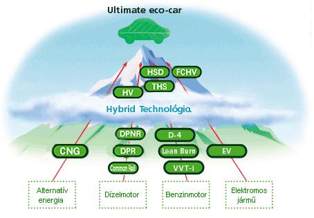
 Trends. 2 Manual Transmission (MT) Trends") Drivetrain 1 Introduction Facing growing demands to help address environmental concerns, automakers are researching, developing, and launching a wide range of drivetrains for gasoline, diesel, hybrid,
Drivetrain 1 Introduction Facing growing demands to help address environmental concerns, automakers are researching, developing, and launching a wide range of drivetrains for gasoline, diesel, hybrid,
MULTIPOINT FUEL INJECTION (MPI) <4G63-Turbo>
 <4G63-Turbo>") 13B-1 GROUP 13B MULTIPOINT FUEL INJECTI (MPI) CTENTS GENERAL INFORMATI........ 13B-2 SENSOR....................... 13B-8 THROTTLE VALVE OPENING ANGLE CTROL.............. 13B-9 FUEL INJECTI
13B-1 GROUP 13B MULTIPOINT FUEL INJECTI (MPI) CTENTS GENERAL INFORMATI........ 13B-2 SENSOR....................... 13B-8 THROTTLE VALVE OPENING ANGLE CTROL.............. 13B-9 FUEL INJECTI
ENGINE CONTROL SYSTEM. 1. General EG-28 ENGINE 2ZR-FE ENGINE. The engine control system for the 2ZR-FE engine has following systems.
 EG-28 ENGINE 2ZR-FE ENGINE ENGINE CONTROL SYSTEM 1. General The engine control system for the 2ZR-FE engine has following systems. System SFI (Sequential Multiport Fuel Injection) ETCS-i (Electronic Throttle
HOT IN START OR RUN JUNCTION BLOCK (BEHIND LEFT SIDE OF DASH)
") of //0 : PM Vehicle Reference: WIRING DIAGRAMS BODY CONTROL MODULES 00 Mitsubishi Diamante.L Eng VR-X Fig : Assist ECU Circuit HOT IN START OR RUN (BEHIND (ON LEFT FRONT FENDER) HOT IN ACC OR RUN (BEHIND
of //0 : PM Vehicle Reference: WIRING DIAGRAMS BODY CONTROL MODULES 00 Mitsubishi Diamante.L Eng VR-X Fig : Assist ECU Circuit HOT IN START OR RUN (BEHIND (ON LEFT FRONT FENDER) HOT IN ACC OR RUN (BEHIND
Gasoline-Electric Hybrid
 Gasoline-Electric Hybrid Foreword This guide was developed to educate and assist emergency responders in the safe handling of the Toyota Prius gasoline-electric hybrid vehicle following an incident. Prius
ANTI-LOCK BRAKE SYSTEM - REAR WHEEL
 ANTI-LOCK BRAKE SYSTEM - REAR WHEEL 1994 Nissan Pickup 1994 BRAKES Nissan - Rear Anti-Lock Pathfinder, Pickup DESCRIPTION In 2WD mode, Rear Anti-Lock Brake System (RABS) helps the driver to maintain steering
CONFIGURATION DIAGRAMS
 80A-1 GROUP 80A CONFIGURATION DIAGRAMS CONTENTS OVERALL CONFIGURATION DIAGRAM...................... 80A-2 HOW TO READ CONFIGURATION DIAGRAMS.................... 80A-3 ENGINE COMPARTMENT......... 80A-4
NEW FEATURES 3E E ENGINE. 1. Description 12 TERCEL NEW FEATURES
 12 TERCEL NEW FEATURES NEW FEATURES 3E E ENGINE 1. Description The 3E E engine is based on the 1.5 liter, 12 valve, OHC 3E engine, but with fuel injection, ignition timing and other engine functions controlled
FOUR-WHEEL ANTI-LOCK BRAKE SYSTEM (4ABS)
") 35B-1 GROUP 35B FOUR-WHEEL ANTI-LOCK BRAKE SYSTEM (4ABS) CONTENTS GENERAL DESCRIPTION......... 35B-2 SENSORS..................... 35B-6 BRAKE MODULATOR (ABS-ECU).. 35B-9 SYSTEM OPERATION............ 35B-10
35B-1 GROUP 35B FOUR-WHEEL ANTI-LOCK BRAKE SYSTEM (4ABS) CONTENTS GENERAL DESCRIPTION......... 35B-2 SENSORS..................... 35B-6 BRAKE MODULATOR (ABS-ECU).. 35B-9 SYSTEM OPERATION............ 35B-10
Engine Control for 1MZ-FE and 3MZ-FE
 Engine Control for MZ-FE and MZ-FE CC * : MZ- FE * : TMC Made * : TMMK Made * : Shielded M I ST - Y - Y 7 M I - ST I Ignition S 8 - IF - M - Y - E IF 8 C - - Y - 0 I E 9 C - 0 M /F 0 EFI EFI elay C/OPN
PROBLEM SYMPTOMS TABLE
 3MZ-FE ENGINE CONTROL SYSTEM SFI SYSTEM 29 SFI SYSTEM PROBLEM SYMPTOMS TABLE Symptom Suspected area See page 1. Starter ST-8 Engine does not crank (Does not start) 2. ST relay ST-2 3. Park/neutral position
13A-1 FUEL CONTENTS MULTIPOINT FUEL INJECTION (MPI) FUEL SUPPLY... 13B
 FUEL SUPPLY... 13B") 13A-1 FUEL CONTENTS MULTIPOINT FUEL INJECTION (MPI)... 13A FUEL SUPPLY... 13B 13A-2 MULTIPOINT FUEL INJECTION (MPI) CONTENTS GENERAL INFORMATION... 3 SERVICE SPECIFICATIONS... 6 SEALANT... 6 SPECIAL TOOLS...
13A-1 FUEL CONTENTS MULTIPOINT FUEL INJECTION (MPI)... 13A FUEL SUPPLY... 13B 13A-2 MULTIPOINT FUEL INJECTION (MPI) CONTENTS GENERAL INFORMATION... 3 SERVICE SPECIFICATIONS... 6 SEALANT... 6 SPECIAL TOOLS...
G ELECTRICAL WIRING ROUTING
 G ELECTRICAL WIRING ROUTING Position of Parts in Engine Compartment A 1 A/C Condenser Fan Motor A 2 A/C Magnetic Clutch and Lock Sensor A 3 A/C Triple Pressure SW (A/C Dual and Signal Pressure SW) A 4
ENGINE MECHANICAL <2.0L ENIGNE>
 11A-1 GROUP 11A ENGINE MECHANICAL CONTENTS GENERAL DESCRIPTION......... 11A-2.................. 11A-3 11A-2 This model is equipped with a newly developed 4B11 engine. It is a 4-cylinder,
AUT LAND. Specification TOYOTA / LEXUS / SCION
 TOOTA / LEXUS / SCION 1991 2012 Version: V2012.05 DATE: MA, 2012 POWER TRAIN SSTEMS CAN SSTEMS, AFTER 2006 SSTEM READ / CLEAR CODE DATA STREAM ACTIVATION ADAPTAION ENGINE Gasoline Engine Diesel Engine
CLUTCH Toyota Celica DESCRIPTION ADJUSTMENTS CLUTCH PEDAL HEIGHT Clutch. Celica
 CLUTCH 1993 Toyota Celica 1993 Clutch Celica DESCRIPTION The single, dry disc type clutch uses a hydraulically operated master cylinder and a release cylinder mounted on clutch housing. Clutch release
1999 Toyota RAV ACCESSORIES & EQUIPMENT Cruise Control Systems - RAV4
 1999 ACCESSORIES & EQUIPMENT Cruise Control Systems - RAV4 DESCRIPTION WARNING: Deactivate air bag system before performing any service operation. See AIR BAG RESTRAINT SYSTEMS article. DO NOT apply electrical
ZF4HP16. Technical Bulletin # Signal Combination L1 L2 L3 L4 P R N D
 Transmission: Subject: Application: Issue Date: Technical Bulletin # 1308 ZF4HP16 Electronical Components Description 2005 Suzuki Forenza L4-2.0L February, 2010 ZF4HP16 Electronical Components Description
SECTION 8 SPECIFICATIONS. Dimensions Service specifications
 SPECIFICATIONS SECTION 8 Dimensions... 342 Engine... 342 Fuel... 342 Service specifications... 343 Tires... 346 Fuses... 347 341 Dimensions Engine Fuel Overall length mm (in.) 4825 (190.0) Overall width
capacity due to increased traction; particularly advantageous on road surfaces
 42-800 Design and function of acceleration slip control (ASR I) A. General B. Driving with ASR I C. Overall function of ASR I D. Location of components E. Individual functions A. General The acceleration
Modern Auto Tech Study Guide Chapter 38 Pages Hybrid Drive Systems 48 Points. Automotive Service
 Modern Auto Tech Study Guide Chapter 38 Pages 694 723 Hybrid Drive Systems 48 Points Automotive Service Hybrid abbreviated version of hybrid electric vehicle (HEV); a type of vehicle that uses two types
MULTIPORT FUEL SYSTEM (MFI)
") 13A-1 GROUP 13A CONTENTS GENERAL INFORMATION...13A-2 CONTROL UNIT...13A-7 SENSOR...13A-9 ACTUATOR...13A-26 FUEL INJECTION CONTROL...13A-31 IGNITION TIMING AND CONTROL FOR CURRENT CARRYING TIME...13A-36
13A-1 GROUP 13A CONTENTS GENERAL INFORMATION...13A-2 CONTROL UNIT...13A-7 SENSOR...13A-9 ACTUATOR...13A-26 FUEL INJECTION CONTROL...13A-31 IGNITION TIMING AND CONTROL FOR CURRENT CARRYING TIME...13A-36
MULTIPOINT FUEL INJECTION (MPI) <4G63-Non-Turbo>
 <4G63-Non-Turbo>") 13A-1 GROUP 13A MULTIPOINT FUEL INJECTI (MPI) CTENTS GENERAL INFORMATI........ 13A-2 FUEL INJECTI CTROL...... 13A-6 IDLE SPEED CTROL (ISC)..... 13A-7 IGNITI TIMING AND DISTRIBUTI CTROL........
13A-1 GROUP 13A MULTIPOINT FUEL INJECTI (MPI) CTENTS GENERAL INFORMATI........ 13A-2 FUEL INJECTI CTROL...... 13A-6 IDLE SPEED CTROL (ISC)..... 13A-7 IGNITI TIMING AND DISTRIBUTI CTROL........
RAV4 Hybrid. Gasoline-Electric Hybrid Synergy Drive
 RAV4 Hybrid Gasoline-Electric Hybrid Synergy Drive AVA42/AVA44 Series Foreword This guide was developed to educate and assist dismantlers in the safe handling of Toyota RAV4 Hybrid gasoline-electric hybrid
Property of American Airlines
 MH Utility Vehicle Section 2 SECTION 2: OPERATION A. CONTROLS, INSTRUMENTS AND SWITCHES The tractor controls and instruments include a headlight switch, ignition switch, hour meter, ammeter (if equipped),
MULTIPOINT FUEL INJECTION (MPI) <4G9>
 <4G9>") MULTIPOINT FUEL INJECTION (MPI) 13C-1 MULTIPOINT FUEL INJECTION (MPI) CONTENTS GENERAL................................. 2 Outline of Changes............................ 2 GENERAL INFORMATION...................
MULTIPOINT FUEL INJECTION (MPI) 13C-1 MULTIPOINT FUEL INJECTION (MPI) CONTENTS GENERAL................................. 2 Outline of Changes............................ 2 GENERAL INFORMATION...................
ENGINE <4G6> 1-1 CONTENTS OVERVIEW... 2 COOLING SYSTEM... 4 MAIN UNIT... 2 INTAKE AND EXHAUST SYSTEMS... 4 LUBRICATION SYSTEM... 2 FUEL SYSTEM...
 1-1 ENGINE CONTENTS OVERVIEW.............................. 2 MAIN UNIT.............................. 2 Pistons.................................... 2 LUBRICATION SYSTEM.................. 2 Oil Pan....................................
Our Businesses. Environment. Safety. Advanced Vehicle Control Systems
 Product Guide By delivering our products and system solutions throughout the world, we can realize an affluent society by creating new value for people, vehicles and society. Our Businesses Environment
LEXUS EXTRA CARE GOLD. VEHICLE SERVICE AGREEMENT offered by LEXUS FINANCIAL SERVICES
 LEXUS EXTRA CARE GOLD VEHICLE SERVICE AGREEMENT offered by LEXUS FINANCIAL SERVICES DRIVE WITH CONFIDENCE KNOWING YOU ARE PROTECTED BY LEXUS EXTRA CARE. Lexus Extra Care, designed with you in mind. Let
Diag. Code 71 EGR System Malfunction CIRCUIT DESCRIPTION. TR-92 ENGINE TROUBLESHOOTING - Circuit Inspection
 TR-92 EINE TROUBLESHOOTI - Circuit Inspection Diag. Code 71 EGR System Malfunction CIRCUIT DESCRIPTION The EGR system is designed to recirculate the exhaust gas properly controlled according to the driving
TROUBLESHOOTING FOR EFI ELECTRONIC CIRCUIT WITH VOLT/OHMMETER
 FI118 TROUBLESHOOTING FOR EFI ELECTRONIC CIRCUIT WITH VOLT/OHMMETER HINT: Because the following troubleshooting procedures are designed for inspection of each separate system, the actual troubleshooting