Industrial Controls. Load Feeders. Configuring the SIRIUS Modular System Selection data for Fuseless and Fused Load Feeders. Configuration Manual
|
|
|
- Lynette Waters
- 6 years ago
- Views:
Transcription

1 Configuration Manual ndustrial Controls Load Feeders Configuring the SRUS Modular System Selection data for Fuseless and Fused Load Feeders Edition 09/2017 siemens.com

2 ntroduction 1 General information 2 ndustrial Controls Load feeders Configuring the SRUS modular system Configuration Manual Selection tables 400 V AC 3 Selection tables 500 V AC 4 Selection tables up to 690 V 5 Fused selection tables up to 690 V 6 nstallation guidelines 7 Service and support 8 09/2017 A8E A/RS-AB/006
3 Legal information Warning notice system This manual contains notices you have to observe in order to ensure your personal safety, as well as to prevent damage to property. The notices referring to your personal safety are highlighted in the manual by a safety alert symbol, notices referring only to property damage have no safety alert symbol. These notices shown below are graded according to the degree of danger. DANGER indicates that death or severe personal injury will result if proper precautions are not taken. WARNNG indicates that death or severe personal injury may result if proper precautions are not taken. CAUTON indicates that minor personal injury can result if proper precautions are not taken. NOTCE indicates that property damage can result if proper precautions are not taken. f more than one degree of danger is present, the warning notice representing the highest degree of danger will be used. A notice warning of injury to persons with a safety alert symbol may also include a warning relating to property damage. Qualified ersonnel The product/system described in this documentation may be operated only by personnel qualified for the specific task in accordance with the relevant documentation, in particular its warning notices and safety instructions. Qualified personnel are those who, based on their training and experience, are capable of identifying risks and avoiding potential hazards when working with these products/systems. roper use of Siemens products Note the following: Trademarks WARNNG Siemens products may only be used for the applications described in the catalog and in the relevant technical documentation. f products and components from other manufacturers are used, these must be recommended or approved by Siemens. roper transport, storage, installation, assembly, commissioning, operation and maintenance are required to ensure that the products operate safely and without any problems. The permissible ambient conditions must be complied with. The information in the relevant documentation must be observed. All names identified by are registered trademarks of Siemens AG. The remaining trademarks in this publication may be trademarks whose use by third parties for their own purposes could violate the rights of the owner. Disclaimer of Liability We have reviewed the contents of this publication to ensure consistency with the hardware and software described. Since variance cannot be precluded entirely, we cannot guarantee full consistency. However, the information in this publication is reviewed regularly and any necessary corrections are included in subsequent editions. Siemens AG Division Digital Factory ostfach NÜRNBERG GERMANY 3ZX1012-0RA21-1AC0 09/2017 Subject to change Copyright Siemens AG All rights reserved
4 Table of contents 1 ntroduction General information Selection tables 400 V AC contactor contactor + thermal overload relay 3RU contactor + 3RB30 / 3RB31 and 3RB20 / 3RB21 solid-state overload relay contactor + 3RB22, 3RB23, 3RB24 electronic overload relays, or 3UF solid-state contactor solid-state reversing contactor star (wye)-delta starting + 3RU21 thermal overload relay contactor assembly for star-delta (wye-delta) start + 3RB3, 3RB22, 3RB23, 3RB24 electronic overload relay, or 3UF RW30 soft RW40 soft RW44 soft Selection tables 500 V AC contactor contactor + 3RU21 thermal overload relay contactor + 3RB3 solid-state overload relay contactor + 3RB22, 3RB23, 3RB24 electronic overload relay, or 3UF contactor assembly for star-delta (wye-delta) start + 3RU21 thermal overload relay contactor assembly for star-delta (wye-delta) start + 3RB22, 3RB23, 3RB24 electronic overload relay, or 3UF7, 3RB RW40 soft RW44 soft Selection tables up to 690 V contactor contactor + 3RU21 thermal overload relay contactor + 3RB3 solid-state overload relay Configuration Manual, 09/2017, A8E A/RS-AB/006
5 Table of contents Type of coordination 1, short-circuit breaking capacity q = 100 ka / 70 ka / 20 ka Type of coordination 2, short-circuit breaking capacity q = 100 ka / 70 ka / 20 ka contactor + 3RB22, 3RB23, 3RB24 electronic overload relay, or 3UF Type of coordination 2, short-circuit breaking capacity q = 100 ka / 70 ka / 50 ka / 20 ka contactor assembly for star-delta (wye-delta) start + 3RU21 thermal overload relay CLASS 10, types of coordination 1 and 2, short-circuit breaking capacity q = 100 ka / 20 ka contactor assembly for star-delta (wye-delta) start + 3RB22, 3RB23, 3RB24 electronic overload relay, or 3UF7, 3RB CLASS 10, types of coordination 1 and 2, short-circuit breaking capacity q = 100 ka / 70 ka / 20 ka RW44 soft CLASS 10, type of coordination Fused selection tables up to 690 V Short-circuit protection: 3RT, 3TF6 contactor, types of coordination 1 and Short-circuit protection 3RU2 thermal overload relay, type of coordination 1 and Short-circuit protection: 3RT2 contactor + 3RU2 thermal overload relay, types of coordination 1 and Short-circuit protection: 3RT contactor, 3TF6 + 3RB3 electronic overload relay Short-circuit protection: 3RT, 3TF6 contactor + 3RB22, 3RB23, 3RB24 electronic overload relay, and 3UF Short-circuit protection: 3RT2 contactor + 3RR2 monitoring relay, types of coordination 1 and Short-circuit protection: 3RW30 soft + 3RT2 contactor + 3RU2 thermal overload relay Short-circuit protection: Solid-state contactor, type of coordination 1 and Short-circuit protection: feeders with 3RW3 + 3RT2 + 3RB30/3RB BS88 fuse links nstallation guidelines Mounting variants under different conditions and frequency of use Minimum clearances to grounded or live parts (400 V / 500 V / 690 V AC) Service and support Siemens ndustry Online Support SRUS nnovations system configurator ndex Configuration Manual, 09/2017, A8E A/RS-AB/006 5
6 ntroduction 1 SRUS modular system The SRUS modular system comprises devices for use in switching, starting, protecting, and monitoring, as well as combinations thereof. Device erformance range / adjustable range 3RT contactors kw ( / AC-3 / 400 V) 3RH contactor relays Switching in the control circuit 3RF solid-state switching devices kw ( / Ue / 400 V) 3RW soft s kw ( / Ue / 400 V) 3RV s 3RU thermal overload relays 3RB electronic overload relays 3RR monitoring relays A A A A The devices named above are supplemented for the main circuit by devices for the control circuit: 3RA28 function modules for mounting on 3RT2 contactors and 3RA27 function modules for connection to the higher-level control. 6 Configuration Manual, 09/2017, A8E A/RS-AB/006


7 ntroduction Switching and starting Table 1-1 Function - switching and starting - contactors Size S00 S0 S2 S3 S6 S10 S12 Table 1-2 Function - switching and starting - solid-state switching devices Size S00 S0 Table 1-3 Function - switching and starting - soft s Size S00 S0 S2 S3 S6 S10 / S12 Configuration Manual, 09/2017, A8E A/RS-AB/006 7


8 ntroduction rotecting Table 1-4 Function - protecting - s Size S00 S0 S2 S3 S6 S10 S12 Table 1-5 Function - protecting - electronic overload relays Size S00 S0 S2 S3 S6 S10 / S12 Table 1-6 Function - protecting - thermal overload relays Size S00 S0 S2 S3 S6 S10 S12 8 Configuration Manual, 09/2017, A8E A/RS-AB/006


9 ntroduction Monitoring Table 1-7 Function - monitoring - monitoring relays Size S00 S0 S2 S3 S6 S10 S12 Feeders Table 1-8 Function - Feeders - pre-assembled load feeders Size S00 S0 S2 S3 S6 S10 S12 Configuration Manual, 09/2017, A8E A/RS-AB/006 9


10 ntroduction Table 1-9 Function - feeders - compact s Size S00 S0 Table 1-10 Components Function modules Size Function modules for mounting on contactors S00 S0 S2 S3 S6 S10 S12 Function modules for connection to the automation level 10 Configuration Manual, 09/2017, A8E A/RS-AB/006

11 ntroduction Highlights Load feeders: Up to 250 kw / 400 V Comprehensive variety of technologies: electromechanical, semiconductors, soft s Short-circuit breaking capacity up to 150 ka Modular design: Coordiated components ensure combinability Variants and sizes: Economical and flexible with 7 sizes and a broader performance range Accessories: Optimum variance with uniform accessories Type of construction: Space-saving design with small device width and butt-mounting type of construction up to 60 C Setup: Fast startup, short setting-up times, and simple wiring Communication: Optional connection to AS-nterface or O-Link with function modules Maintenance: Extremely durable, low maintenance, and reliable Approvals: Global approvals and certifications, such as UL, CSA, CCC, shipbuilding... Mounting: ermanently secure mounting, screw or snap fitting Spring-loaded connection technology: Quick and secure connection, vibration-proof, and maintenance-free Environment: Environment friendly production and materials, recycling capability, low power loss Design: Clear-cut, ergonomic design (winner of the if roduct Design Award) Configuration Manual, 09/2017, A8E A/RS-AB/006 11
12 General information 2 General criteria for the selection of devices The s, contactors, solid-state switching devices, soft s and overload relays in the following tables are all specified in their basic versions with screw terminals, i.e. (in particular) without accessories. Where available, of course, versions with spring-loaded terminals or ring cable lug connections as well as accessories such as auxiliary switches, auxiliary trip units etc. can be used. The contactors listed have a rated control supply voltage Us of 230 V AC, 50 Hz. Versions with other voltages can also be used. The 3RU21 thermal overload relay and the 3RB30 / 3RB31 electronic overload relays can be directly mounted onto the contactor. The 3RB22 / 3RB23 / 3RB24 electronic overload relay and the SMOCODE pro 3UF7 protection and control device are essentially used for stand-alone installation. n their basic version, these devices are specified with a rated control supply voltage of 230 V AC. Note When designing a system, comply with all valid national installation specifications and standards. Mounting the combinations When mounting the devices, specific arcing spaces must be maintained so that short-circuits can be cleared safely and reliably. The appropriate installation guidelines can be found in Section nstallation guidelines (age 232). The technical data of the individual devices must be taken into account when selecting a device. 400 V / 500 V / 690 V AC The tables below are primarily structured for the 400 V, 500 V and 690 V line voltages for grounded networks (at 50 and 60 Hz) generally found in EC regions. Tests are carried out with a test voltage which lies 10% above these values (further details can be found in the test reports). Thus, the specified combinations can also be used for other networks as long as their maximum voltage does not exceed the test voltage. This means, for instance, the combinations for 400 V can also be used for 415 V networks that have a line supply tolerance of +5%. The tables shown in this document are always based on certificates of compliance with the order and on test reports. f more detailed information is required, these can be downloaded from the Siemens ndustry Online Support ( portal. 12 Configuration Manual, 09/2017, A8E A/RS-AB/006
13 General information Ambient conditions A maximum ambient temperature of 60 C applies to all electromechanical controlgear, and 40 C to soft s and solid-state contactors. Higher temperatures are possible with derating. For details, refer to the System Manual or contact Technical Assistance. A maximum installation height of 2000 m applies to electromechanical controlgear, and 1000 m to soft s and solid-state contactors. Higher installation altitudes are also possible with derating. For details refer to the appropriate manuals. Trip classes CLASS 5, CLASS 10, CLASS 20, CLASS 30 and CLASS 40 Trip classes, according to EC , define the time intervals within which the protection equipment (overload release of a or overload relay) must trip from the cold state, for a symmetrical, three-phase load with a 7.2-fold set e. The tripping times are as follows: CLASS 5 and CLASS 10 between 2 s and 10 s, CLASS 20 between 4 s and 20 s, CLASS 30 between 9 s and 30 s, CLASS 40 between 30 s and 40 s. n practice, devices with trip CLASS 5 and CLASS 10 are generally used. These devices are designed for standard applications. CLASS 5 and CLASS 10 are often referred to as normal starting. Combinations for CLASS 20, CLASS 30 and CLASS 40 are available for applications where a higher starting is required for a prolonged period. n this case, using standard devices of CLASS 5 and CLASS 10 would result in unwanted tripping. CLASS 20, CLASS 30 and CLASS 40 are also known as heavy starting devices. Large fan are an example of this type of application. As well as the overload protection devices, the contactors and short-circuit protection devices must also be designed for these long starting times. This is why combinations acc. to CLASS 5 and CLASS 10 are generally more cost-effective. CLASS 20, CLASS 30 and CLASS 40 are only generally used if genuinely necessitated by the application. Configuration Manual, 09/2017, A8E A/RS-AB/006 13
14 General information Type of coordination 1 or 2 When selecting the combinations, in many cases, either coordination type 1 or 2 can be selected. According to EC , the coordination type defines the permissible degree of damage for a device following a short-circuit. Type of coordination 1: After a short-circuit, it is permissible for the to be inoperative, in particular, damage to the contactor, solid-state switching devices and overload relay is permissible. Type of coordination 2: The is still operative. There must be no signs of damage to the devices, with the exception of slightly welded contactor contacts if these can be easily separated again without any noticeable deformation. n both cases, the short-circuit is reliably and safely cleared. Combinations of coordination type 2 are therefore of a higher quality and are rapidly available for reuse after a short-circuit. n the case of solid-state switching devices, the same applies as for type of coordination 2, that the short-circuit is cleared without any damage to the power semiconductors. Combinations of coordination type 1 are generally the more favorably priced solution. Combinations of coordination type 2 automatically fulfill the requirements of coordination type 1. Tests All of the specified combinations are tested in compliance with EC Configuration Manual, 09/2017, A8E A/RS-AB/006
15 General information With or without overload relay n addition to the combinations comprising a (for protection) and contactor, combinations are also available with (for protection), contactor and overload relay. n the first case, the assumes the dual function of overload protection and short-circuit protection, while in the second case, the assumes only the short-circuit protection function and the overload relay the overload protection function. The tripping behavior of both solutions under overload and short-circuit conditions is technically comparable. For fuseless load feeders with electronic overload relays, and for higher trip classes, CLASS 20, CLASS 30 and CLASS 40 in particular, a is often used instead of an MS for combinations. This is due to the following: from the point of view of thermal destruction limits, MSs for combinations are generally designed for CLASS 10 starts. The measurement of electronic overload relays usually moves into saturation upwards of a 10-fold rated, so that the intrinsic protection of the is no longer guaranteed for higher trip classes. n order to ensure thermal intrinsic protection, it is advisable to use a /circuit breaker that protects itself over the overload release. The /circuit breaker is selected so that the point at which the characteristic curve of the overload relay intersects with the a-tripping characteristic of the /circuit breaker is more than 10 x the set. This ensures that, in the case of faults, such as overload or blocking, the overload relay always trips and not the. n this situation, combinations with and contactor offer the most costeffective solution. However, combinations with overload relays offer distinct advantages for certain applications: 3RB30 / 3RB31 and 3RB22 / 3RB23 / 3RB24 electronic overload relays or SMOCODE pro 3UF7 can be used to achieve not only trip CLASS 5 and CLASS 10 but also solutions for heavy starting, such as CLASS 20, CLASS 30, and CLASS 40. Using electronic overload relays offers a wide setting range of 1:4 or 1:10. This offers advantages during configuration (e.g. if the exact is not known) and enables us to reduce the number of variants required. and short-circuit protection are carried out separately and can also be signaled separately. Alternatively, the 3RV2921-1M signaling block can be used for the 3RV instead of the overload relay. This also supports the separate signaling of overloads and short-circuits. Setting of the overload relay to "Automatic Reset" can also save a walk to the control cabinet in the case of overload tripping, as a manual reset in the control cabinet is not required. Alternatively, this function can also be implemented with the "3RV21 with overload relay function". These devices can be used in the + contactor tables instead of the 3RV20. Configuration Manual, 09/2017, A8E A/RS-AB/006 15
16 General information Star(wye)(Y)-delta function(δ) starting n order to keep the peaks in the line supply as low as possible, contactor assembly are frequently used as star(wye)-delta s to start three-phase. However, to make worthwhile use of YΔ starting, a low load torque is required during starting. Only then can the approximately reach its rated speed in the Y stage before switching to Δ operation. An overload relay should be used for overload protection. Normally, this is located directly in the feeder cable U1, V1, W1, as shown in the circuit diagram. Using this arrangement, the overload protection is effective in both the Y and Δ circuit. The overload relay should be set for 58% of the rated. The control wiring and switching from Y to Δ are implemented with plug-on function modules for the SRUS innovations. The switching time can be set between 1 and 100 s. The function modules thus perform the function of the timing relay. n the tables, circuit breakers are used for combinations (without overload releases). However, 3RV20 s for protection with the same rated can also be used instead. n this case, the rated of the must be set to the maximum value. This prevents a simultaneous tripping of the and overload relay. 16 Configuration Manual, 09/2017, A8E A/RS-AB/006
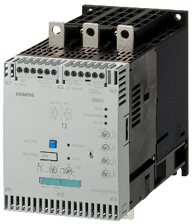
17 General information Soft starting with soft s What is the basic principle of a soft? Soft s limit the starting and starting torque. This reliably prevents mechanical stress and mains voltage dips. The voltage is reduced using phase control and is increased from an adjustable starting voltage up to the mains voltage within a specific ramp time. Soft starting and stopping reduces the stress on connected equipment, thus ensuring prolonged smooth and trouble-free production. 3RW30 soft s for the soft starting of three-phase asynchronous for simple applications performance range: up to 55 kw at 400 V (75 hp at 460 V) 3RW40 soft s with integrated functions; electronic overload and intrinsic device protection and adjustable limiting performance range: up to 250 kw at 400 V (300 hp at 460 V) The 3RW44 solid-state soft s offer the following: soft starting and stopping electronic overload and intrinsic device protection adjustable limiting numerous functions for higher-level requirements performance range: up to 710 kw at 400 V in standard circuit up to 1200 kw at 400 V (1700 hp at 460 V) in the inside-delta circuit More information can be found on the nternet ( Configuration Manual, 09/2017, A8E A/RS-AB/006 17
18 General information For the correct dimensioning of soft s for with high starting ratios (/e >= 8), we recommend our Simulation Tool for Soft Starters (STS) : Download ( Readme ( Load feeders with soft s Soft s can also be used to prevent peaks in the line supply instead of the star(wye)-delta starting combinations. Three versions of these soft s are available: 3RW30 3RW40 3RW44 The 3RW4 soft s come as standard with an integrated solid-state overload relay. This means that, in fuseless combinations, a is only required for shortcircuit protection. n the case of 3RW30 soft s, the must also cover the overload protection. 18 Configuration Manual, 09/2017, A8E A/RS-AB/006
19 General information 3RB22 / 23 / 24 overload relays and SMOCODE pro The modular, electronic overload relays with external power supply type 3RB22 / 23/ 24 for high-feature applications up to 630 A have been designed for inverse-time delayed protection of loads with normal and heavy starting against excessive temperature rises due to overload, phase unbalance or phase failure. SMOCODE pro is a flexible, modular management system for with constant speeds in the low-voltage performance range. t provides the intelligent, communicationcapable interface between the higher-level automation system and the feeder. A configuration with 3RB22 / 23 / 24 overload relays and with SMOCODE pro requires in each case a basic unit, a connection cable, and a measuring module. The article numbers of the measuring modules are listed in the tables. Details of the basic units and connection cables are given in the following: 3RB22 / 23 / 24 Basic unit (= evaluation module) Monostable, screw: 3RB2283-4AA1 Bistable, screw: 3RB2383-4AA1 Monostable, spring-loaded: 3RB2283-4AC1 Bistable, spring-loaded: 3RB2383-4AC1 Monostable, screw: 3RB2483-4AA1 Monostable, spring-loaded: 3RB2483-4AC1 Connection cable 0.1 m (S00-S3): 3RB2987-2B 0.5 m (S00-S12): 3RB2987-2D For other accessories for 3RB22 / 23 / 24 overload relays see Catalog C 10 Chapter 7. Configuration Manual, 09/2017, A8E A/RS-AB/006 19
20 General information SMOCODE pro SMOCODE pro C, Basic Unit 1 ROFBUS D interface, 12 Mbit/s, RS485 4 / 3O freely assignable, input for thermistor connection, monostable relay outputs 24 V DC: 3UF7000-1AB V AC / DC: 3UF7000-1AU00-0 SMOCODE pro V, Basic Unit 2 ROFBUS D interface, 12 Mbit/s, RS485 4 / 3O freely assignable, input for thermistor connection, monostable relay outputs, can be expanded by expansion modules 24 V DC: 3UF7010-1AB V AC / DC: 3UF7010-1AU00-0 SMOCODE pro C ROFBUS D interface, 12 Mbps, RS485 4 / 3O freely assignable, input for thermistor connection, monostable relay outputs 24 V DC: 3UF7000-1AB V AC/DC: 3UF7000-1AU00-0 SMOCODE pro S ROFBUS D interface, 15 Mbps, RS485 4 / 2O freely assignable, input for thermistor connection, monostable relay outputs, can be expanded by multifunction module 24 V DC: 3UF7020-1AB V AC/DC: 3UF7020-1AU01-0 SMOCODE pro V ROFBUS D interface, 12 Mbps, RS485 4 / 3O freely assignable, input for thermistor connection, monostable relay outputs, can be expanded by expansion modules 24 V DC: 3UF7010-1AB V AC/DC: 3UF7010-1AU Configuration Manual, 09/2017, A8E A/RS-AB/006
21 General information SMOCODE pro V ROFNET ETHERNET/ROFNET O, OC UA server and web server, 100 Mbps, 2 x connection to bus through RJ45, ROFNET system redundancy, media redundancy protocol, 4 /3 O freely assignable, input for thermistor connection, monostable relay outputs, can be expanded by expansion modules, web server in German/English/Chinese/Russian 24 V DC: UF7011-1AB V AC/DC: 3UF7011-1AU00-0 SMOCODE pro V Modbus RTU Modbus RTU interface, 57.6 Mbps, RS485 4 / 3O freely assignable, input for thermistor connection, monostable relay outputs, can be expanded by expansion modules 24 V DC: 3UF7012-1AB V AC/DC: 3UF7012-1AU00-0 Connection cable 0.1 m, flat: 3UF7931-0AA m, flat: 3UF7935-0AA m, flat: 3UF7932-0AA m, round: 3UF7932-0BA m, round: 3UF7937-0BA m, round: 3UF7933-0BA00-0 For other accessories and software for SMOCODE pro see Catalog C 10 Chapter 10. Note The coordination tests with SMOCODE pro measuring modules 3UF710 apply to the same extent for measuring modules / voltage measuring modules 3UF711.. of the same rated range. Configuration Manual, 09/2017, A8E A/RS-AB/006 21


22 General information Link modules Table 2-1 Connection system Screw-type connection system Link module versions Link module version contactor in size S00 Article number 3RA1921-1DA00 contactor in size S0 AC 3RA2921-1AA00 contactor in size S0 DC soft in size S00 soft in size S0 solid-state contactor 3RA2921-1BA00 contactor in size S2 soft in size S2 3RA2931-1AA00 contactor in size S3 3RA1941-1AA00 22 Configuration Manual, 09/2017, A8E A/RS-AB/006


23 General information Connection system Springloaded connection system Link module version contactor in size S00 Article number 3RA2911-2AA00 contactor in size S0 3RA2921-2AA00 soft in size S00 3RA2911-2GA00 soft in size S0 3RA2921-2GA00 Configuration Manual, 09/2017, A8E A/RS-AB/006 23


24 General information Connection system Hybrid connection system 1) Link module version contactor in size S00 Article number 3RA2911-2FA00 contactor in size S0 3RA2921-2FA00 1) The has a screw terminal. The contactor has a spring-loaded terminal. 24 Configuration Manual, 09/2017, A8E A/RS-AB/006
25 Selection tables 400 V AC contactor CLASS 10, type of coordination 1, short-circuit breaking capacity q = 150 ka three-phase 400 V AC 1) output for protection 4) Maximum permitted setting range overload release E1 / E2 E3 / E4 Contactor 2) Size kw A A A Article No. Article No RV2011-0AA10 S00/S RV2011-0BA10 S00/S RV2011-0CA10 S00/S RV2011-0DA10 S00/S RV2011-0EA10 S00/S RV2011-0FA10 S00/S RV2011-0GA10 S00/S RV2011-0HA10 S00/S RV2011-0JA10 S00/S RV2011-0KA10 S00/S RV2011-1AA10 S00/S RV2011-1BA10 S00/S RV2011-1CA10 S00/S RV2011-1DA10 S00/S RV2011-1EA10 S00/S RV2011-1FA10 S00/S RV2011-1GA10 S00/S RV2011-1HA10 S00/S RV2011-1JA10 3RT2016- S00/S RV2011-1KA10 3RT2017- S00/S RV2011-4AA10 3RT2018- S00/S00 Configuration Manual, 09/2017, A8E A/RS-AB/006 25
26 Selection tables 400 V AC contactor three-phase 400 V AC 1) output for protection 4) Maximum permitted setting range overload release E1 / E2 E3 / E4 Contactor 2) Size kw A A A Article No. Article No RV2021-4BA10 3RT2025- S0/S RV2021-4CA10 3RT2026- S0/S RV2021-4DA10 3RT2026- S0/S RV2021-4NA10 S0/S (up to 256 A starting ) 3RV2021-4EA10 S0/S ) Use size S2 3RV2021-4A10 3RT2028- S0/S ) Use size S2 3RV2021-4FA10 3RT2028- S0/S RV2032-4A10 S2/S RV2032-4UA10 S2/S RV2032-4VA10 3RT2036- S2/S RV2032-4WA10 3RT2036- S2/S RV2032-4XA10 S2/S RV2032-4JA10 S2/S RV2032-4KA10 3RT2038- S2/S (up to 720 A starting ) 3RV2032-4RA10 3RT2038- S2/S RV2042-4RA10 3RT2045- S3/S RV2042-4RA10 3RT2046- S3/S RV2042-4YA10 3RT2046- S3/S RV2042-4MA10 3RT2047- S3/S3 26 Configuration Manual, 09/2017, A8E A/RS-AB/006
27 Selection tables 400 V AC contactor three-phase 400 V AC 1) output for protection 4) Maximum permitted setting range overload release E1 / E2 E3 / E4 Contactor 2) kw A A A Article No. Article No VA2216-7MN32 3RT1054- /S VA2216-7MN32 3RT1055- /S VA2220-7MN32 3RT1056- /S VA2325-7MN32 3RT1064- /S VA2325-7MN32 3RT1264- /S10V VA2440-7MN32 3RT1065- /S VA2440-7MN32 3RT1265- /S10V VA2440-7MN32 3RT1066- /S VA2440-7MN32 3RT1266- /S10V VA2450-7MN32 3RT1075- /S VA2450-7MN32 3RT1275- /S12V VA2450-7MN32 3RT1076- /S VA2450-7MN32 3RT1276- /S12V Article numbers for basic versions with screw terminals and spring-loaded terminals also possible. 1) Guide value for 4-pole standard at 400 V AC, 50 Hz. Selection depends on the concrete startup and rated data of the protected. 2) Rated control supply voltage 230 V AC, 50 Hz, other control voltages possible. 3) Discrete mounting only without a link module, short-circuit breaking capacity q = 55 ka 4) switching operations with circuit breaker 3VA are not allowed. Size Configuration Manual, 09/2017, A8E A/RS-AB/006 27
28 Selection tables 400 V AC contactor CLASS 10, type of coordination 2, short-circuit breaking capacity q = 150 ka three-phase 400 V AC 1) output (guide value) for protection 3) Maximum permitted setting range overload release E1 / E2 E3 / E4 Contactor 2) Size kw A A A Article No. Article No RV2011-0AA10 S00/S RV2011-0BA10 S00/S RV2011-0CA10 S00/S RV2011-0DA10 S00/S RV2011-0EA10 S00/S RV2011-0FA10 S00/S RV2011-0GA10 S00/S RV2011-0HA10 S00/S RV2011-0JA10 S00/S RV2011-0KA10 S00/S RV2011-1AA10 S00/S RV2011-1BA10 S00/S RV2011-1CA10 S00/S RV2011-1DA10 S00/S RV2011-1EA10 S00/S RV2011-1FA10 S00/S RV2011-1GA10 S00/S RV2011-1HA10 S00/S RV2011-1JA10 S00/S RV2011-1KA10 S00/S RV2011-4AA10 3RT2026- S00/S RV2021-4BA10 S0/S RV2021-4CA10 S0/S RV2021-4DA10 S0/S RV2021-4NA10 S0/S (up to 256 A starting ) 3RV2021-4EA10 S0/S0 28 Configuration Manual, 09/2017, A8E A/RS-AB/006
29 Selection tables 400 V AC contactor three-phase 400 V AC 1) output (guide value) for protection 3) Maximum permitted setting range overload release E1 / E2 E3 / E4 Contactor 2) kw A A A Article No. Article No RV2032-4EA10 S2/S RV2032-4A10 S2/S RV2032-4UA10 S2/S RV2032-4VA10 3RT2036- S2/S RV2032-4WA10 3RT2036- S2/S RV2032-4XA10 S2/S RV2032-4JA10 S2/S RV2032-4KA10 3RT2038- S2/S (up to 720 A starting ) Size 3RV2032-4RA10 3RT2038- S2/S RV2042-4RA10 3RT2045- S3/S RV2042-4RA10 3RT2046- S3/S RV2042-4YA10 3RT2046- S3/S RV2042-4MA10 3RT2047- S3/S VA2216-7MN32 3RT1054- /S VA2216-7MN32 3RT1055- /S VA2220-7MN32 3RT1056- /S VA2325-7MN32 3RT1064- /S VA2325-7MN32 3RT1264- /S10V VA2440-7MN32 3RT1065- /S VA2440-7MN32 3RT1265- /S10V VA2440-7MN32 3RT1066- /S VA2440-7MN32 3RT1266- /S10V VA2450-7MN32 3RT1075- /S VA2450-7MN32 3RT1275- /S12V VA2450-7MN32 3RT1076- /S VA2450-7MN32 3RT1276- /S12V Article numbers for basic versions with screw terminals and spring-loaded terminals also possible. 1) Guide value for 4-pole standard at 400 V AC, 50 Hz. Selection depends on the concrete startup and rated data of the protected. 2) Rated control supply voltage 230 V AC, 50 Hz, other control voltages possible. 3) switching operations with circuit breaker 3VA are not allowed. Configuration Manual, 09/2017, A8E A/RS-AB/006 29
30 Selection tables 400 V AC contactor + thermal overload relay 3RU contactor + thermal overload relay 3RU21 CLASS 10, type of coordination 1, short-circuit breaking capacity q = 150 ka threephase 4-pole at 400 V AC 1) output Starter protection Contactor 2) Size relay (thermal) 3) Maximum permitted setting range overload release E1 / E2 E3 / E4 kw A Article No. Article No. Size Article No. A A RV2311-0BC RV2311-0CC RV2311-0DC RV2311-0EC RV2311-0FC RV2311-0GC RV2311-0HC RV2311-0JC RV2311-0KC RV2311-1AC RV2311-1BC RV2311-1CC RV2311-1DC RV2311-1EC10 S00/S00/S00 0BB S00/S00/S00 0CB S00/S00/S00 0DB S00/S00/S00 0EB S00/S00/S00 0FB S00/S00/S00 0GB S00/S00/S00 0HB S00/S00/S00 0JB S00/S00/S00 0KB S00/S00/S00 1AB S00/S00/S00 1BB S00/S00/S00 1CB S00/S00/S00 1DB S00/S00/S00 1EB Configuration Manual, 09/2017, A8E A/RS-AB/006
31 Selection tables 400 V AC contactor + thermal overload relay 3RU21 threephase 4-pole at 400 V AC 1) output Starter protection Contactor 2) Size relay (thermal) 3) Maximum permitted setting range overload release E1 / E2 E3 / E4 kw A Article No. Article No. Size Article No. A A RV2311-1FC RV2311-1GC RV2311-1HC RV2311-1JC10 3RT RV2311-1KC10 3RT RV2311-4AC10 3RT RV2321-4AC10 3RT RV2321-4BC10 3RT RV2321-4CC10 3RT RV2321-4DC10 3RT RV2321-4NC RV2321-4EC10 S00/S00/S00 1FB S00/S00/S00 1GB S00/S00/S00 1HB S00/S00/S00 1JB S00/S00/S00 1KB S00/S00/S00 4AB S0/S0/S0 4AB S0/S0/S0 4BB S0/S0/S0 4CB S0/S0/S0 4DB S0/S0/S0 4NB S0/S0/S0 4EB (up to 256 A starting ) Configuration Manual, 09/2017, A8E A/RS-AB/006 31
32 Selection tables 400 V AC contactor + thermal overload relay 3RU21 threephase 4-pole at 400 V AC 1) output Starter protection Contactor 2) Size relay (thermal) 3) Maximum permitted setting range overload release E1 / E2 kw A Article No. Article No. Size Article No. A A RV2332-4EC RV2332-4C RV2332-4UC RV2332-4VC10 3RT RV2332-4WC10 3RT RV2332-4XC RV2332-4JC RV2332-4KC10 3RT RV2332-4RC10 3RT RV2342-4RC10 3RT RV2342-4RC10 3RT RV2342-4YC10 3RT RV2342-4MC10 3RT2047- E3 / E4 S2/S2/S2 3RU2136-4EB S2/S2/S2 3RU2136-4FB S2/S2/S2 3RU2136-4FB S2/S2/S2 3RU2136-4GB S2/S2/S2 3RU2136-4HB S2/S2/S2 3RU2136-4QB S2/S2/S2 3RU2136-4JB S2/S2/S2 3RU2136-4KB S2/S2/S2 3RU2136-4RB (up to 720 A) (up to 720 A starting ) S3/S3/S3 3RU2146-4LB S3/S3/S3 3RU2146-4LB S3/S3/S3 3RU2146-4LB S3/S3/S3 3RU2146-4MB Article numbers for basic versions with screw terminals and spring-loaded terminals also possible. 1) Guide value for 4-pole standard at 400 V AC, 50 Hz. Selection depends on the concrete startup and rated data of the protected. 2) Rated control supply voltage 230 V AC, 50 Hz, other control voltages possible. 3) Assembled combinations of three are not permitted. 32 Configuration Manual, 09/2017, A8E A/RS-AB/006
33 Selection tables 400 V AC contactor + thermal overload relay 3RU21 CLASS 10, type of coordination 2, short-circuit breaking capacity q = 150 ka threephase 400 V AC 1) Starter protection Contactor 2) Size relay (thermal) 3) Maximum permitted setting range overload release output E1 / E2 E3 / E4 kw A Article No. Article No. Article No. A A RV2311-0BC RV2311-0CC RV2311-0DC RV2311-0EC RV2311-0FC RV2311-0GC RV2311-0HC RV2311-0JC RV2311-0KC RV2311-1AC RV2311-1BC RV2311-1CC RV2311-1DC RV2311-1EC RV2311-1FC RV2311-1GC10 S00/S00/S00 0BB S00/S00/S00 0CB S00/S00/S00 0DB S00/S00/S00 0EB S00/S00/S00 0FB S00/S00/S00 0GB S00/S00/S00 0HB S00/S00/S00 0JB S00/S00/S00 0KB S00/S00/S00 1AB S00/S00/S00 1BB S00/S00/S00 1CB S00/S00/S00 1DB S00/S00/S00 1EB S00/S0/S00 1FB S00/S0/S0 1GB0 4) Configuration Manual, 09/2017, A8E A/RS-AB/006 33
34 Selection tables 400 V AC contactor + thermal overload relay 3RU21 threephase 400 V AC 1) Starter protection Contactor 2) Size relay (thermal) 3) Maximum permitted setting range overload release output E1 / E2 E3 / E4 kw A Article No. Article No. Article No. A A RV2311-1HC RV2311-1JC RV2311-1KC RV2311-4AC10 3RT RV2321-4BC RV2321-4CC RV2321-4DC RV2321-4NC RV2321-4EC RV2332-4EC RV2332-4C RV2332-4UC RV2332-4VC10 3RT RV2332-4WC10 3RT RV2332-4XC RV2332-4JC RV2332-4KC10 3RT RV2332-4RC10 3RT2038- S00/S0/S0 1HB0 4) S00/S0/S0 1JB0 4) S00/S0/S0 1KB0 4) S00/S0/S0 4AB0 4) S0/S0/S0 4BB S0/S0/S0 4CB S0/S0/S0 4DB S0/S0/S0 4NB S0/S0/S0 4EB (up to 256 A starting ) S2/S2/S2 3RU2136-4EB S2/S2/S2 3RU2136-4FB S2/S2/S2 3RU2136-4FB S2/S2/S2 3RU2136-4GB S2/S2/S2 3RU2136-4HB S2/S2/S2 3RU2136-4QB S2/S2/S2 3RU2136-4JB S2/S2/S2 3RU2136-4KB S2/S2/S2 3RU2136-4RB (up to 720 A) (up to 720 A starting ) 34 Configuration Manual, 09/2017, A8E A/RS-AB/006
35 Selection tables 400 V AC contactor + thermal overload relay 3RU21 threephase 400 V AC 1) output Starter protection Contactor 2) Size relay (thermal) 3) Maximum permitted setting range overload release E1 / E2 kw A Article No. Article No. Article No. A A RV2342-4RC10 3RT RV2342-4RC10 3RT RV2342-4YC10 3RT RV2342-4MC10 3RT2047- E3 / E4 S3/S3/S3 3RU2146-4LB S3/S3/S3 3RU2146-4LB S3/S3/S3 3RU2146-4LB S3/S3/S3 3RU2146-4MB Article numbers for basic versions with screw terminals and spring-loaded terminals also possible. 1) Guide value for 4-pole standard at 400 V AC, 50 Hz. Selection depends on the concrete startup and rated data of the protected. 2) Rated control supply voltage 230 V AC, 50 Hz, other control voltages possible. 3) Assembled combinations of three are not permitted. 4) Can also be used in size S00 (3RU2116). Configuration Manual, 09/2017, A8E A/RS-AB/006 35
36 Selection tables 400 V AC contactor + 3RB30 / 3RB31 and 3RB20 / 3RB21 solid-state overload relay contactor + 3RB30 / 3RB31 and 3RB20 / 3RB21 solid-state overload relay Type of coordination 1, short-circuit breaking capacity q = 150 ka/100 ka threephase 400 V AC 1) Circuit breaker Starter protection 3) Contactor 2) Size relay (electronic) Maximum permitted setting range overload release power Setting range release E1 / E2 E3 / E4 kw A A Article No. Article No. Article No. CLASS 10, short-circuit breaking capacity q = 150 ka None 3RV2311-0CC None 3RV2311-0DC None 3RV2311-0HC None 3RV2311-0JC None 3RV2311-0KC None 3RV2311-1AC None 3RV2311-1BC None 3RV2311-1BC None 3RV2311-1DC None 3RV2311-1EC10 S00/S00/S00 S00/S00/S00 S00/S00/S00 S00/S00/S00 S00/S00/S00 S00/S00/S00 S00/S00/S00 S00/S00/S00 S00/S00/S00 S00/S00/S00 3RB3016-1RB0 3RB3016-1RB0 3RB3016-1NB0 3RB3016-1NB0 3RB3016-1NB0 3RB3016-1B0 3RB3016-1B0 3RB3016-1B0 3RB3016-1B0 3RB3016-1SB0 A A Configuration Manual, 09/2017, A8E A/RS-AB/006
37 Selection tables 400 V AC contactor + 3RB30 / 3RB31 and 3RB20 / 3RB21 solid-state overload relay threephase 400 V AC 1) Circuit breaker Starter protection 3) Contactor 2) Size relay (electronic) Maximum permitted setting range overload release power Setting range release E1 / E2 E3 / E4 kw A A Article No. Article No. Article No None 3RV2311-1GC None 3RV2311-1HC None 3RV2311-1JC10 3RT None 3RV2311-4AC None 3RV2321-4BC10 3RT None 3RV2321-4EC None 3RV2332-4EC None 3RV2332-4VC10 3RT RV2032-4KA10 3RT RV2032-4RA10 3RT None 3RV2342-4FC10 3RT None 3RV2342-4HC10 3RT None 3RV2342-4JC10 3RT None 3RV2342-4KC10 3RT None 3RV2342-4RC10 3RT None 3RV2342-4YC10 3RT2046- S00/S00/S00 S00/S00/S00 S00/S00/S00 S00/S0/S0 S0/S0/S0 S0/S0/S0 S2/S2/S2 S2/S2/S2 S2/S2/S2 S2/S2/S2 S3/S3/S3 S3/S3/S3 S3/S3/S3 S3/S3/S3 S3/S3/S3 S3/S3/S3 3RB3016-1SB0 3RB3016-1SB0 3RB3016-1TB0 3RB3026-1QB0 3RB3026-1QB0 3RB3026-1VB0 3RB3036-1UB0 3RB3036-1UB0 3RB3036-1UB0 3RB3036-1UB0 3RB3046-1UB0 3RB3046-1XB0 3RB3046-1XB0 3RB3046-1XB0 3RB3046-1XB0 3RB3046-1XB0 A A (up to 256 A starting ) Configuration Manual, 09/2017, A8E A/RS-AB/006 37
38 Selection tables 400 V AC contactor + 3RB30 / 3RB31 and 3RB20 / 3RB21 solid-state overload relay threephase 400 V AC 1) Circuit breaker Starter protection 3) Contactor 2) Size relay (electronic) Maximum permitted setting range overload release power Setting range release E1 / E2 E3 / E4 kw A A Article No. Article No. Article No None 3VA2216-7MS32 3RT None 3VA2216-7MS32 3RT None 3VA2220-7MS32 3RT None 3VA2325-7MS32 3RT None 3VA2325-7MS32 3RT None 3VA2440-7MS32 3RT None 3VA2440-7MS32 3RT None 3VA2440-7MS32 3RT None 3VA2440-7MS32 3RT None 3VA2450-7MS32 3RT None 3VA2450-7MS32 3RT None 3VA2450-7MS32 3RT None 3VA2450-7MS32 3RT1276- /S6/S6 /S6/S6 /S6/S6 /S10/S10 /S10V/S10 /S10/S10 /S10V/S10 /S10/S10 /S10V/S10 /S12/S12 /S12V/S12 /S12/S12 /S12V/S12 3RB2056-1FC2 3RB2056-1FC2 3RB2056-1FC2 3RB2066-1GC2 3RB2066-1GC2 3RB2066-1GC2 3RB2066-1GC2 3RB2066-1MC2 3RB2066-1MC2 3RB2066-1MC2 3RB2066-1MC2 3RB2066-1MC2 3RB2066-1MC2 A A Configuration Manual, 09/2017, A8E A/RS-AB/006
39 Selection tables 400 V AC contactor + 3RB30 / 3RB31 and 3RB20 / 3RB21 solid-state overload relay threephase 400 V AC 1) power Circuit breaker Starter protection 3) Setting range release Contactor 2) Size relay (electronic) kw A A Article No. Article No. Article No. CLASS 10, short-circuit breaking capacity q = 100 ka None 3RV2331-4EC None 3RV2331-4VC10 3RT RV2031-4VB10 3RT RV2031-4WB10 3RT RV2031-4JB None 3RV2341-4FC10 3RT None 3RV2341-4HC10 3RT None 3RV2341-4JC10 3RT None 3RV2341-4KC10 3RT None 3RV2341-4RC10 3RT None 3RV2341-4YC10 3RT None 3VA1112-5MH32 3RT1054-1A None 3VA1216-5MH32 3RT None 3VA1220-5MH32 3RT1056- S2/S2/S2 S2/S2/S2 S2/S2/S2 S2/S2/S2 S2/S2/S2 S3/S3/S3 S3/S3/S3 S3/S3/S3 S3/S3/S3 S3/S3/S3 S3/S3/S3 /S6/S6 /S6/S6 /S6/S6 Maximum permitted setting range overload release 3RB3036-1UB0 3RB3036-1UB0 3RB3036-1UB0 3RB3036-1WB0 3RB3036-1WB0 3RB3046-1UB0 3RB3046-1XB0 3RB3046-1XB0 3RB3046-1XB0 3RB3046-1XB0 3RB3046-1XB0 3RB2056-1FC2 3RB2056-1FC2 3RB2056-1FC2 E1 / E2 A E3 / E4 A Article numbers for basic versions with screw terminals and spring-loaded terminals also possible. 3RA2921-1BA00 link module can only be used with screw terminals. 1) Guide value for 4-pole standard at 400 V AC, 50 Hz. Selection depends on the concrete startup and rated data of the protected. 2) Rated control supply voltage 230 V AC, 50 Hz, other control voltages possible. 3) The is to be set to maximum value. Configuration Manual, 09/2017, A8E A/RS-AB/006 39
40 Selection tables 400 V AC contactor + 3RB30 / 3RB31 and 3RB20 / 3RB21 solid-state overload relay Type of coordination 2, short-circuit breaking capacity q = 150 ka/100 ka threephase 400 V AC 1) Starter protection 3) Contactor 2) Size relay (electronic) Maximum permitted setting range overload release power Setting range release E1 / E2 E3 / E4 kw A A Article No. Article No. Article No. A A CLASS 5, short-circuit breaking capacity q = 150 ka None 3RV2311-0CC None 3RV2311-0DC None 3RV2311-0FC None 3RV2311-0HC None 3RV2311-0JC None 3RV2311-0KC None 3RV2311-1AC None 3RV2311-1BC None 3RV2311-1DC None 3RV2311-1EC None 3RV2321-1GC None 3RV2321-1HC None 3RV2321-1JC10 S00/S00/S00 S00/S00/S00 S00/S00/S00 S00/S00/S00 S00/S00/S00 S00/S00/S00 S00/S00/S00 S00/S00/S00 S00/S00/S00 S00/S00/S00 S0/S0/S0 S0/S0/S0 S0/S0/S0 3RB3113-4RB0 3RB3113-4RB0 3RB3113-4NB0 3RB3113-4NB0 3RB3113-4NB0 3RB3113-4B0 3RB3113-4B0 3RB3113-4B0 3RB3113-4B0 3RB3113-4SB0 3RB3123-4SB0 3RB3123-4SB0 3RB3123-4QB Configuration Manual, 09/2017, A8E A/RS-AB/006
41 Selection tables 400 V AC contactor + 3RB30 / 3RB31 and 3RB20 / 3RB21 solid-state overload relay threephase 400 V AC 1) Starter protection 3) Contactor 2) Size relay (electronic) Maximum permitted setting range overload release power Setting range release E1 / E2 E3 / E4 kw A A Article No. Article No. Article No. A A None 3RV2321-1KC10 S0/S0/S0 3RB QB None 3RV2321-4AC10 3RT None 3RV2321-4CC None 3RV2321-4EC None 3RV2332-4EC None 3RV2332-4UC None 3RV2332-4VC10 3RT RV2032-4KA10 3RT None 3RV2342-4HC10 3RT None 3RV2342-4JC10 3RT None 3RV2342-4KC10 3RT None 3RV2342-4RC10 3RT None 3RV2342-4YC10 3RT None 3RV2342-4MC10 3RT2047- S0/S0/S0 S0/S0/S0 S0/S0/S0 S2/S2/S2 S2/S2/S2 S2/S2/S2 S2/S2/S2 S3/S3/S3 S3/S3/S3 S3/S3/S3 S3/S3/S3 S3/S3/S3 S3/S3/S3 3RB3123-4QB0 3RB3123-4VB0 3RB3123-4VB0 3RB3133-4UB0 3RB3133-4UB0 3RB3133-4UB0 3RB3133-4WB0 3RB3143-4UB0 3RB3143-4XB0 3RB3143-4XB0 3RB3143-4XB0 3RB3143-4XB0 3RB3143-4XB (up to 256 A starting ) Configuration Manual, 09/2017, A8E A/RS-AB/006 41
42 Selection tables 400 V AC contactor + 3RB30 / 3RB31 and 3RB20 / 3RB21 solid-state overload relay threephase 400 V AC 1) Starter protection 3) Contactor 2) Size relay (electronic) Maximum permitted setting range overload release power Setting range release E1 / E2 E3 / E4 kw A A Article No. Article No. Article No. A A CLASS 5, short-circuit breaking capacity q = 100 ka None 3RV2331-4EC None 3RV2331-4C None 3RV2331-4JC RV2031-4JB None 3RV2341-4HC10 3RT None 3RV2341-4JC10 3RT None 3RV2341-4KC10 3RT None 3RV2341-4RC10 3RT None 3RV2341-4YC10 3RT None 3RV2341-4MC10 3RT2047- CLASS 10, short-circuit breaking capacity q = 150 ka None 3RV2311-0CC None 3RV2311-0DC None 3RV2311-0HC None 3RV2311-0JC None 3RV2311-0KC None 3RV2311-1AC None 3RV2311-1BC10 S2/S2/S2 S2/S2/S2 S2/S2/S2 S2/S2/S2 S3/S3/S3 S3/S3/S3 S3/S3/S3 S3/S3/S3 S3/S3/S3 S3/S3/S3 S00/S00/S00 S00/S00/S00 S00/S00/S00 S00/S00/S00 S00/S00/S00 S00/S00/S00 S00/S00/S00 3RB3133-4UB0 3RB3133-4UB0 3RB3133-4WB0 3RB3133-4WB0 3RB3143-4UB0 3RB3143-4XB0 3RB3143-4XB0 3RB3143-4XB0 3RB3143-4XB0 3RB3143-4XB0 3RB3016-1RB0 3RB3016-1RB0 3RB3016-1NB0 3RB3016-1NB0 3RB3016-1NB0 3RB3016-1B0 3RB3016-1B Configuration Manual, 09/2017, A8E A/RS-AB/006
43 Selection tables 400 V AC contactor + 3RB30 / 3RB31 and 3RB20 / 3RB21 solid-state overload relay threephase 400 V AC 1) Starter protection 3) Contactor 2) Size relay (electronic) Maximum permitted setting range overload release power Setting range release E1 / E2 E3 / E4 kw A A Article No. Article No. Article No. A A None 3RV2311-1BC10 S00/S00/S00 3RB B None 3RV2311-1DC None 3RV2311-1EC None 3RV2321-1GC None 3RV2321-1HC None 3RV2321-1JC None 3RV2321-4AC10 3RT None 3RV2321-4BC None 3RV2321-4EC None 3RV2332-4EC None 3RV2332-4VC10 3RT RV2032-4KA10 3RT RV2032-4RA10 3RT None 3RV2342-4FC10 3RT None 3RV2342-4HC10 3RT None 3RV2342-4JC10 3RT None 3RV2342-4KC10 3RT2045- S00/S00/S00 S00/S00/S00 S0/S0/S0 S0/S0/S0 S0/S0/S0 S0/S0/S0 S0/S0/S0 S0/S0/S0 S2/S2/S2 S2/S2/S2 S2/S2/S2 S2/S2/S2 S3/S3/S3 S3/S3/S3 S3/S3/S3 S3/S3/S3 3RB3016-1B0 3RB3016-1SB0 3RB3026-1SB0 3RB3026-1SB0 3RB3026-1QB0 3RB3026-1QB0 3RB3026-1QB0 3RB3026-1VB0 3RB3036-1UB0 3RB3036-1UB0 3RB3036-1UB0 3RB3036-1UB0 3RB3046-1UB0 3RB3046-1XB0 3RB3046-1XB0 3RB3046-1XB (up to 256 A starting ) Configuration Manual, 09/2017, A8E A/RS-AB/006 43
44 Selection tables 400 V AC contactor + 3RB30 / 3RB31 and 3RB20 / 3RB21 solid-state overload relay threephase 400 V AC 1) Starter protection 3) Contactor 2) Size relay (electronic) Maximum permitted setting range overload release power Setting range release E1 / E2 E3 / E4 kw A A Article No. Article No. Article No. A A None 3RV2342-4RC10 3RT2046- S3/S3/S3 3RB XB None 3RV2342-4YC10 3RT None 3VA2216-7MS32 3RT None 3VA2216-7MS32 3RT None 3VA2220-7MS32 3RT None 3VA2325-7MS32 3RT None 3VA2325-7MS32 3RT None 3VA2440-7MS32 3RT None 3VA2440-7MS32 3RT None 3VA2440-7MS32 3RT None 3VA2440-7MS32 3RT None 3VA2450-7MS32 3RT None 3VA2450-7MS32 3RT None 3VA2450-7MS32 3RT None 3VA2450-7MS32 3RT1276- S3/S3/S3 /S6/S6 /S6/S6 /S6/S6 /S10/S10 /S10V/S10 /S10/S10 /S10V/S10 /S10/S10 /S10V/S10 /S12/S12 /S12V/S12 /S12/S12 /S12V/S12 3RB3046-1XB0 3RB2056-1FC2 3RB2056-1FC2 3RB2056-1FC2 3RB2066-1GC2 3RB2066-1GC2 3RB2066-1GC2 3RB2066-1GC2 3RB2066-1MC2 3RB2066-1MC2 3RB2066-1MC2 3RB2066-1MC2 3RB2066-1MC2 3RB2066-1MC Configuration Manual, 09/2017, A8E A/RS-AB/006
45 Selection tables 400 V AC contactor + 3RB30 / 3RB31 and 3RB20 / 3RB21 solid-state overload relay threephase 400 V AC 1) Starter protection 3) Contactor 2) Size relay (electronic) Maximum permitted setting range overload release power Setting range release E1 / E2 E3 / E4 kw A A Article No. Article No. Article No. A A CLASS 10, short-circuit breaking capacity q = 100 ka None 3RV2331-4EC None 3RV2331-4VC10 3RT RV2031-4VB10 3RT RV2031-4WB10 3RT RV2031-4JB None 3RV2341-4FC10 3RT None 3RV2341-4HC10 3RT None 3RV2341-4JC10 3RT None 3RV2341-4KC10 3RT None 3RV2341-4RC10 3RT None 3RV2341-4YC10 3RT None 3VA1112-5MH32 3RT None 3VA1216-5MH32 3RT None 3VA1220-5MH32 3RT1056- S2/S2/S2 S2/S2/S2 S2/S2/S2 S2/S2/S2 S2/S2/S2 S3/S3/S3 S3/S3/S3 S3/S3/S3 S3/S3/S3 S3/S3/S3 S3/S3/S3 /S6/S6 /S6/S6 /S6/S6 3RB3036-1UB0 3RB3036-1UB0 3RB3036-1UB0 3RB3036-1WB0 3RB3036-1WB0 3RB3046-1UB0 3RB3046-1XB0 3RB3046-1XB0 3RB3046-1XB0 3RB3046-1XB0 3RB3046-1XB0 3RB2056-1FC2 3RB2056-1FC2 3RB2056-1FC Configuration Manual, 09/2017, A8E A/RS-AB/006 45
46 Selection tables 400 V AC contactor + 3RB30 / 3RB31 and 3RB20 / 3RB21 solid-state overload relay threephase 400 V AC 1) Starter protection 3) Contactor 2) Size relay (electronic) Maximum permitted setting range overload release power Setting range release E1 / E2 E3 / E4 kw A A Article No. Article No. Article No. A A CLASS 20, short-circuit breaking capacity q = 150 ka RV2011-0FA RV2011-0HA RV2011-0JA RV2011-1AA RV2011-1BA RV2011-1CA RV2011-1DA RV2021-1FA RV2021-1GA RV2021-1HA RV2021-1JA RV2021-4AA10 3RT RV2021-4BA RV2021-4DA None 3RV2332-4XC RV2032-4XA RV2032-4RA10 3RT RV2042-4FB10 3RT2045- S00/S00/S00 S00/S00/S00 S00/S00/S00 S00/S00/S00 S00/S00/S00 S00/S00/S00 S00/S00/S00 S0/S0/S0 S0/S0/S0 S0/S0/S0 S0/S0/S0 S0/S0/S0 S0/S0/S0 S0/S0/S0 S2/S2/S2 S2/S2/S2 S2/S2/S2 S3/S3/S3 3RB3016-2RB0 3RB3016-2RB0 3RB3016-2NB0 3RB3016-2NB0 3RB3016-2NB0 3RB3016-2B0 3RB3016-2B0 3RB3026-2B0 3RB3026-2B0 3RB3026-2B0 3RB3026-2SB0 3RB3026-2QB0 3RB3026-2QB0 3RB3026-2QB0 3RB3036-2UB0 3RB3036-2UB0 3RB3036-2UB0 3RB3046-2UB Configuration Manual, 09/2017, A8E A/RS-AB/006
47 Selection tables 400 V AC contactor + 3RB30 / 3RB31 and 3RB20 / 3RB21 solid-state overload relay threephase 400 V AC 1) Starter protection 3) Contactor 2) Size relay (electronic) Maximum permitted setting range overload release power Setting range release E1 / E2 E3 / E4 kw A A Article No. Article No. Article No. A A RV2042-4HB10 3RT2045- S3/S3/S3 3RB UB RV2042-4JB10 3RT RV2042-4KB10 3RT RV2042-4RB10 3RT RV2042-4YB10 3RT1054-1A None 3VA2163-7MS32 3RT / / 80 None 3VA2110-7MS32 3RT None 3VA2216-7MS32 3RT None 3VA2216-7MS32 3RT None 3VA2216-7MS32 3RT None 3VA2220-7MS32 3RT None 3VA2325-7MS32 3RT None 3VA2325-7MS32 3RT None 3VA2325-7MS32 3RT None 3VA2325-7MS32 3RT None 3VA2325-7MS32 3RT None 3VA2325-7MS32 3RT None 3VA2440-7MS32 3RT1266- S3/S3/S3 S3/S3/S3 S3/S3/S3 S3/S6/S3 /S6/S6 /S6/S6 /S6/S6 /S6/S6 /S10/S10 /S10/S10 /S10V/S10 /S10/S10 /S10V/S10 /S10/S10 /S12/S12 /S10V/S10 /S10V/S10 3RB3046-2UB0 3RB3046-2XB0 3RB3046-2XB0 3RB3046-2XW1 3RB2056-2FC2 3RB2056-2FC2 3RB2056-2FC2 3RB2056-2FC2 3RB2066-2GC2 3RB2066-2GC2 3RB2066-2GC2 3RB2066-2GC2 3RB2066-2MC2 3RB2066-2MC2 3RB2066-2MC2 3RB2066-2MC2 3RB2066-2MC Configuration Manual, 09/2017, A8E A/RS-AB/006 47
48 Selection tables 400 V AC contactor + 3RB30 / 3RB31 and 3RB20 / 3RB21 solid-state overload relay threephase 400 V AC 1) Starter protection 3) Contactor 2) Size relay (electronic) Maximum permitted setting range overload release power Setting range release E1 / E2 E3 / E4 kw A A Article No. Article No. Article No. A A None 3VA2440-7MS32 3RT1076- /S12/S12 3RB MC None 3VA2450-7MN32 3RT None 3VA2450-7MN32 3RT1276- CLASS 20, short-circuit breaking capacity q = 100 ka RV2031-4B RV2031-4B RV2031-4UB RV2031-4WB10 3RT RV2031-4XB10 CLASS 30, short-circuit breaking capacity q = 150 ka RV2011-0HA RV2011-0JA RV2011-1AA RV2011-1BA RV2011-1CA RV2011-1DA RV2021-1FA RV2021-1GA RV2021-1HA10 /S12V/S12 /S12V/S12 S2/S2/S2 S2/S2/S2 S2/S2/S2 S2/S2/S2 S2/S2/S2 S00/S00/S00 S00/S00/S00 S00/S00/S00 S00/S00/S00 S00/S00/S00 S00/S00/S00 S0/S0/S0 S0/S0/S0 S0/S0/S0 3RB2066-2MC2 3RB2066-2MC2 3RB3036-2UB0 3RB3036-2UB0 3RB3036-2UB0 3RB3036-2UB0 3RB3036-2UB0 3RB3113-4RB0 3RB3113-4RB0 3RB3113-4NB0 3RB3113-4NB0 3RB3113-4NB0 3RB3113-4B0 3RB3123-4B0 3RB3123-4B0 3RB3123-4B Configuration Manual, 09/2017, A8E A/RS-AB/006
49 Selection tables 400 V AC contactor + 3RB30 / 3RB31 and 3RB20 / 3RB21 solid-state overload relay threephase 400 V AC 1) Starter protection 3) Contactor 2) Size relay (electronic) Maximum permitted setting range overload release power Setting range release E1 / E2 E3 / E4 kw A A Article No. Article No. Article No. A A RV2021-1JA RV2021-4AA10 3RT RV2021-4BA RV2021-4DA RV2021-4EA RV2032-4KA10 3RT RV2032-4KA10 3RT RV2042-4FB10 3RT RV2042-4HB10 3RT RV2042-4JB10 3RT RV2042-4KB10 3RT RV2042-4RB10 3RT RV2042-4YB10 3RT RV2042-4MB10 3RT1054-1A None 3VA2110-7MS32 3RT None 3VA2110-7MS32 3RT None 3VA2216-7MS32 3RT None 3VA2216-7MS32 3RT1056- S0/S0/S0 S0/S0/S0 S0/S0/S0 S0/S0/S0 S0/S0/S0 S2/S2/S2 S2/S2/S2 S3/S3/S3 S3/S3/S3 S3/S3/S3 S3/S3/S3 S3/S3/S3 S3/S3/S3 S3/S6/S3 /S6/S6 /S6/S6 /S6/S6 /S6/S6 3RB3123-4SB0 3RB3123-4SB0 3RB3123-4QB0 3RB3123-4QB0 3RB3123-4QB0 3RB3133-4UB0 3RB3133-4UB0 3RB3143-4UB0 3RB3143-4UB0 3RB3143-4UB0 3RB3143-4UB0 3RB3143-4XB0 3RB3143-4XB0 3RB3143-4XW1 3RB2153-4FC2 3RB2153-4FC2 3RB2153-4FC2 3RB2153-4FC (up to 256 A starting ) Configuration Manual, 09/2017, A8E A/RS-AB/006 49
50 Selection tables 400 V AC contactor + 3RB30 / 3RB31 and 3RB20 / 3RB21 solid-state overload relay threephase 400 V AC 1) power Starter protection 3) Setting range release Contactor 2) Size relay (electronic) Maximum permitted setting range overload release E1 / E2 E3 / E4 kw A A Article No. Article No. Article No. A A None 3VA2220-7MS32 3RT1065- /S10/S10 3RB GC None 3VA2325-7MS32 3RT None 3VA2325-7MS32 3RT None 3VA2325-7MS32 3RT None 3VA2325-7MS32 3RT None 3VA2325-7MS32 3RT None 3VA2440-7MS32 3RT None 3VA2440-7MS32 3RT None 3VA2450-7MQ32 3RT1276- CLASS 30, short-circuit breaking capacity q = 100 ka RV2031-4EB RV2031-4VB10 3RT RV2031-4XB10 /S10/S10 /S10V/S10 /S12/S12 /S10V/S10 /S12/S12 /S12/S12 /S12V/S12 /S12V/S12 S2/S2/S2 S2/S2/S2 S2/S2/S2 3RB2163-4GC2 3RB2163-4GC2 3RB2163-4MC2 3RB2163-4MC2 3RB2163-4MC2 3RB2163-4MC2 3RB2163-4MC2 3RB2163-4MC2 3RB3133-4UB0 3RB3133-4UB0 3RB3133-4WB Article numbers for basic versions with screw terminals and spring-loaded terminals also possible. 3RA2921-1BA00 link module can only be used with screw terminals. 1) Guide value for 4-pole standard at 400 V AC, 50 Hz. Selection depends on the concrete startup and rated data of the protected. 2) Rated control supply voltage 230 V AC, 50 Hz, other control voltages possible. 3) The is to be set to maximum value. 50 Configuration Manual, 09/2017, A8E A/RS-AB/006
51 Selection tables 400 V AC contactor + 3RB22, 3RB23, 3RB24 electronic overload relays, or 3UF contactor + 3RB22, 3RB23, 3RB24 electronic overload relays, or 3UF7 Type of coordination 1, short-circuit breaking capacity q = 150 ka threephase 400 V AC 1) output Setting range release Starter protection 3) Contactor 2) Size relay (electronic) or measuring module 4) Maximum permitted setting range overload release E1 / E2 E3 / E4 kw A A Article No. Article No. Article No. A A CLASS 10, short-circuit breaking capacity q = 150 ka None 3RV2311-0DC10 S00/S00/ 3UF71x0-2BG None 3RV2311-0FC10 S00/S00/ 3UF71x0-2BG None 3RV2311-0HC10 S00/S00/ 3UF71x0-2BG None 3RV2311-0JC10 S00/S00/ 3UF71x0-2BG None 3RV2311-0KC None 3RV2311-1AC10 S00/S00/ S00/S00/ 3UF71x0-2BG1 3UF71x0-2BG Configuration Manual, 09/2017, A8E A/RS-AB/006 51
52 Selection tables 400 V AC contactor + 3RB22, 3RB23, 3RB24 electronic overload relays, or 3UF7 threephase 400 V AC 1) output Setting range release Starter protection 3) Contactor 2) Size relay (electronic) or measuring module 4) Maximum permitted setting range overload release E1 / E2 E3 / E4 kw A A Article No. Article No. Article No. A A None 3RV2311-1BC10 S00/S00/ 3UF71x0-2BG None 3RV2311-1DC None 3RV2311-1EC None 3RV2311-1GC None 3RV2311-1HC10 S00/S00/ S00/S00/ S00/S00/ S00/S00/ 3UF71x1-2DG1 3UF71x1-2DG1 3UF71x1-2DG1 3UF71x1-2DG None 3RV2311-1JC10 3RT2016- S00/S00/ 3UF71x1-2DG None 3RV2321-4AC None 3RV2321-4CC None 3RV2321-4EC None 3RV2332-4EC10 S0/S0/ 3RT2026- S0/S0/ S0/S0/ S2/S2/ 3UF71x1-2DG1 3UF71x1-2DG1 3UF71x2-2JG1 3UF71x2-2JG (up to 256 A starting ) Configuration Manual, 09/2017, A8E A/RS-AB/006
53 Selection tables 400 V AC contactor + 3RB22, 3RB23, 3RB24 electronic overload relays, or 3UF7 threephase 400 V AC 1) output Setting range release Starter protection 3) Contactor 2) Size relay (electronic) or measuring module 4) Maximum permitted setting range overload release E1 / E2 E3 / E4 kw A A Article No. Article No. Article No. A A None 3RV2332-4VC10 3RT2036- S2/S2/ 3UF71x2-2JG RV2032-4XA10 S2/S2/ 3UF71x2-2JG RV2032-4RA10 3RT2038- S2/S2/ 3UF71x2-2JG None 3RV2342-4FC10 3RT2045- S3/S3/ 3UF71x2-2JG None 3RV2342-4HC10 3RT2045- S3/S3/ 3UF71x2-2JG None 3RV2342-4JC10 3RT2045- S3/S3/ 3UF71x2-2JG None 3RV2342-4KC None 3RV2342-4RC None 3RV2342-4YC None 3VA2216-7MS32 3RT2045- S3/S3/ 3RT2046- S3/S3/ 3RT2046- S3/S3/ 3RT1054- /S6/S6 3UF71x2-2JG1 3UF71x2-2JG1 3UF71x2-2JG1 3UF71x3-1xA00-0/ 3RB2956-2Tx Configuration Manual, 09/2017, A8E A/RS-AB/006 53
54 Selection tables 400 V AC contactor + 3RB22, 3RB23, 3RB24 electronic overload relays, or 3UF7 threephase 400 V AC 1) output Setting range release Starter protection 3) Contactor 2) Size relay (electronic) or measuring module 4) Maximum permitted setting range overload release E1 / E2 E3 / E4 kw A A Article No. Article No. Article No. A A None 3VA2216-7MS32 3RT1055- /S6/S6 3UF71x3-1xA00-0/ 3RB2956-2Tx None 3VA2220-7MS None 3VA2325-7MS None 3VA2325-7MS None 3VA2440-7MS None 3VA2440-7MS None 3VA2440-7MS None 3VA2440-7MS32 3RT1056- /S6/S6 3UF71x3-1xA00-0/ 3RB2956-2Tx2 3RT1064- /S10/S10 3UF71x4-1BA00-0/ 3RB2966-2WH2 3RT1264- /S10V/S10 3UF71x4-1BA00-0/ 3RB2966-2WH2 3RT1065- /S10/S10 3UF71x4-1BA00-0/ 3RB2966-2WH2 3RT1265- /S10V/S10 3UF71x4-1BA00-0/ 3RB2966-2WH2 3RT1066- /S10/S10 3UF71x4-1BA00-0/ 3RB2966-2WH2 3RT1266- /S10V/S10 3UF71x4-1BA00-0/ 3RB2966-2WH Configuration Manual, 09/2017, A8E A/RS-AB/006
55 Selection tables 400 V AC contactor + 3RB22, 3RB23, 3RB24 electronic overload relays, or 3UF7 threephase 400 V AC 1) output Setting range release Starter protection 3) Contactor 2) Size relay (electronic) or measuring module 4) Maximum permitted setting range overload release E1 / E2 E3 / E4 kw A A Article No. Article No. Article No. A A None 3VA2450-7MS32 3RT1075- /S12/S12 3UF71x4-1BA00-0/ 3RB2966-2WH None 3VA2450-7MS None 3VA2450-7MS None 3VA2450-7MS32 3RT1275- /S12V/S12 3UF71x4-1BA00-0/ 3RB2966-2WH2 3RT1076- /S12/S12 3UF71x4-1BA00-0/ 3RB2966-2WH2 3RT1276- /S12V/S12 3UF71x4-1BA00-0/ 3RB2966-2WH Article numbers for basic versions with screw terminals and spring-loaded terminals also possible. 3RA2921-1BA00 link module can only be used with screw terminals. 1) Guide value for 4-pole standard at 400 V AC, 50 Hz. Selection depends on the concrete startup and rated data of the protected. 2) Rated control supply voltage 230 V AC, 50 Hz, other control voltages possible. 3) The is to be set to maximum value. 4) The necessary measuring modules (x = 0) or the measuring modules / voltage measuring modules (x = 1) are specified. The corresponding basic units 3RB22 / 3RB23 / 3RB24 and 3UF7 are additionally required. Configuration Manual, 09/2017, A8E A/RS-AB/006 55
56 Selection tables 400 V AC contactor + 3RB22, 3RB23, 3RB24 electronic overload relays, or 3UF7 Type of coordination 2, short-circuit breaking capacity q = 150 ka/100 ka three-phase 400 V AC 1) output Setting range release Starter protection 3) Contactor 2) Size relay (electronic) or measuring module 4) Maximum permitted setting range overload release E1 / E2 E3 / E4 kw A A Article No. Article No. Article No. A A CLASS 5, short-circuit breaking capacity q = 150 ka None 3RV2311-0DC None 3RV2311-0FC None 3RV2311-0HC None 3RV2311-0JC None 3RV2311-0KC None 3RV2311-1AC None 3RV2311-1BC None 3RV2311-1DC None 3RV2311-1EC None 3RV2321-1GC None 3RV2321-1HC None 3RV2321-1JC None 3RV2321-1KC None 3RV2321-4AC10 3RT2026- S00/S00/ S00/S00/ S00/S00/ S00/S00/ S00/S00/ S00/S00/ S00/S00/ S00/S00/ S00/S00/ S0/S0/ S0/S0/ S0/S0/ S0/S0/ S0/S0/ 3UF71x0-2BG1 3UF71x0-2BG1 3UF71x0-2BG1 3UF71x0-2BG1 3UF71x0-2BG1 3UF71x0-2BG1 3UF71x0-2BG1 3UF71x0-2BG1 3UF71x1-2DG1 3UF71x1-2DG1 3UF71x1-2DG1 3UF71x1-2DG1 3UF71x1-2DG1 3UF71x1-2DG Configuration Manual, 09/2017, A8E A/RS-AB/006
57 Selection tables 400 V AC contactor + 3RB22, 3RB23, 3RB24 electronic overload relays, or 3UF7 three-phase 400 V AC 1) output Setting range release Starter protection 3) Contactor 2) Size relay (electronic) or measuring module 4) Maximum permitted setting range overload release E1 / E2 E3 / E4 kw A A Article No. Article No. Article No. A A None 3RV2321-4CC None 3RV2321-4EC None 3RV2332-4EC None 3RV2332-4UC None 3RV2332-4VC RV2032-4KA None 3RV2342-4HC None 3RV2342-4JC None 3RV2342-4KC None 3RV2342-4RC None 3RV2342-4YC None 3RV2342-4MC10 3RT2036-3RT2038-3RT2045-3RT2045-3RT2045-3RT2046-3RT2046-3RT2047- S0/S0/ S0/S0/ S2/S2/ S2/S2/ S2/S2/ S2/S2/ S3/S3/ S3/S3/ S3/S3/ S3/S3/ S3/S3/ S3/S3/ 3UF71x1-2DG1 3UF71x2-2JG1 3UF71x2-2JG1 3UF71x2-2JG1 3UF71x2-2JG1 3UF71x2-2JG1 3UF71x2-1AA00-0 2JG1 3UF71x2-2JG1 3UF71x2-2JG1 3UF71x2-2JG1 3UF71x2-2JG1 3UF71x2-2JG (up to 256 A starting ) Configuration Manual, 09/2017, A8E A/RS-AB/006 57
58 Selection tables 400 V AC contactor + 3RB22, 3RB23, 3RB24 electronic overload relays, or 3UF7 three-phase 400 V AC 1) output Setting range release Starter protection 3) Contactor 2) Size relay (electronic) or measuring module 4) Maximum permitted setting range overload release E1 / E2 E3 / E4 kw A A Article No. Article No. Article No. A A CLASS 5, short-circuit breaking capacity q = 100 ka None 3RV2331-4EC None 3RV2331-4UC None 3RV2331-4WC RV2031-4JB None 3RV2341-4HC None 3RV2341-4JC None 3RV2341-4KC None 3RV2341-4RC None 3RV2341-4YC None 3RV2341-4MC10 3RT2036-3RT2045-3RT2045-3RT2045-3RT2046-3RT2046-3RT2047- CLASS 10, short-circuit breaking capacity q = 150 ka None 3RV2311-0DC None 3RV2311-0FC None 3RV2311-0HC None 3RV2311-0JC None 3RV2311-0KC None 3RV2311-1AC None 3RV2311-1BC None 3RV2311-1DC10 S2/S2/ S2/S2/ S2/S2/ S2/S2/ S3/S3/ S3/S3/ S3/S3/ S3/S3/ S3/S3/ S3/S3/ S00/S00/ S00/S00/ S00/S00/ S00/S00/ S00/S00/ S00/S00/ S00/S00/ S00/S00/ 3UF71x2-2JG1 3UF71x2-2JG1 3UF71x2-2JG1 3UF71x2-2JG1 3UF71x2-2JG1 3UF71x2-2JG1 3UF71x2-2JG1 3UF71x2-2JG1 3UF71x2-2JG1 3UF71x2-2JG1 3UF71x0-2BG1 3UF71x0-2BG1 3UF71x0-2BG1 3UF71x0-2BG1 3UF71x0-2BG1 3UF71x0-2BG1 3UF71x0-2BG1 3UF71x1-2DG Configuration Manual, 09/2017, A8E A/RS-AB/006
59 Selection tables 400 V AC contactor + 3RB22, 3RB23, 3RB24 electronic overload relays, or 3UF7 three-phase 400 V AC 1) output Setting range release Starter protection 3) Contactor 2) Size relay (electronic) or measuring module 4) Maximum permitted setting range overload release E1 / E2 E3 / E4 kw A A Article No. Article No. Article No. A A None 3RV2311-1EC None 3RV2321-1GC None 3RV2321-1HC None 3RV2321-1JC None 3RV2321-4AC None 3RV2321-4CC None 3RV2321-4EC None 3RV2332-4EC None 3RV2332-4VC RV2032-4XA RV2032-4RA None 3RV2342-4FC None 3RV2342-4HC None 3RV2342-4JC None 3RV2342-4KC None 3RV2342-4RC None 3RV2342-4YC None 3VA2216-7MS None 3VA2216-7MS32 3RT2026-3RT2036-3RT2038-3RT2045-3RT2045-3RT2045-3RT2045-3RT2046-3RT2046-3RT1054-3RT1055- S00/S00/ S0/S0/ S0/S0/ S0/S0/ S0/S0/ S0/S0/ S0/S0/ S2/S2/ S2/S2/ S2/S2/ S2/S2/ S3/S3/ S3/S3/ S3/S3/ S3/S3/ S3/S3/ S3/S3/ /S6/S6 /S6/S6 3UF71x1-2DG1 3UF71x1-2DG1 3UF71x1-2DG1 3UF71x1-2DG1 3UF71x1-2DG1 3UF71x1-2DG1 3UF71x2-2JG1 3UF71x2-2JG1 3UF71x2-2JG1 3UF71x2-2JG1 3UF71x2-2JG1 3UF71x2-2JG1 3UF71x2-2JG1 3UF71x2-2JG1 3UF71x2-2JG1 3UF71x2-2JG1 3UF71x2-2JG1 3UF71x3-1xA00-0/ 3RB2956-2Tx2 3UF71x3-1xA00-0/ 3RB2956-2Tx (up to 256 A starting ) Configuration Manual, 09/2017, A8E A/RS-AB/006 59
60 Selection tables 400 V AC contactor + 3RB22, 3RB23, 3RB24 electronic overload relays, or 3UF7 three-phase 400 V AC 1) output Setting range release Starter protection 3) Contactor 2) Size relay (electronic) or measuring module 4) Maximum permitted setting range overload release E1 / E2 E3 / E4 kw A A Article No. Article No. Article No. A A None 3VA2220-7MS None 3VA2325-7MS None 3VA2325-7MS None 3VA2440-7MS None 3VA2440-7MS None 3VA2440-7MS None 3VA2440-7MS None 3VA2450-7MS None 3VA2450-7MS None 3VA2450-7MS None 3VA2450-7MS32 3RT1056-3RT1064-3RT1264-3RT1065-3RT1265-3RT1066-3RT1266-3RT1075-3RT1275-3RT1076-3RT1276- CLASS 10, short-circuit breaking capacity q = 100 ka None 3RV2331-4EC None 3RV2031-4VC RV2031-4UB RV2031-4WB None 3RV2341-4FC None 3RV2341-4HC None 3RV2341-4JC None 3RV2341-4KC10 3RT2036-3RT2036-3RT2045-3RT2045-3RT2045-3RT2045- /S6/S6 3UF71x3-1xA00-0/ 3RB2956-2Tx2 /S10/S10 3UF71x4-1BA00-0/ 3RB2966-2WH2 /S10V/S10 3UF71x4-1BA00-0/ 3RB2966-2WH2 /S10/S10 3UF71x4-1BA00-0/ 3RB2966-2WH2 /S10V/S10 3UF71x4-1BA00-0/ 3RB2966-2WH2 /S10/S10 3UF71x4-1BA00-0/ 3RB2966-2WH2 /S10V/S10 3UF71x4-1BA00-0/ 3RB2966-2WH2 /S12/S12 3UF71x4-1BA00-0/ 3RB2966-2WH2 /S12V/S12 3UF71x4-1BA00-0/ 3RB2966-2WH2 /S12/S12 3UF71x4-1BA00-0/ 3RB2966-2WH2 /S12V/S12 3UF71x4-1BA00-0/ 3RB2966-2WH2 S2/S2/ S2/S2/ S2/S2/ S2/S2/ S3/S3/ S3/S3/ S3/S3/ S3/S3/ 3UF71x2-2JG1 3UF71x2-2JG1 3UF71x2-2JG1 3UF71x2-2JG1 3UF71x2-2JG1 3UF71x2-2JG1 3UF71x2-2JG1 3UF71x2-2JG Configuration Manual, 09/2017, A8E A/RS-AB/006
61 Selection tables 400 V AC contactor + 3RB22, 3RB23, 3RB24 electronic overload relays, or 3UF7 three-phase 400 V AC 1) output Setting range release Starter protection 3) Contactor 2) Size relay (electronic) or measuring module 4) Maximum permitted setting range overload release E1 / E2 E3 / E4 kw A A Article No. Article No. Article No. A A None 3RV2341-4RC None 3RV2341-4YC10 3RT2046-3RT2046- CLASS 20, short-circuit breaking capacity q = 150 ka RV2011-0HA RV2011-0JA RV2011-1AA RV2011-1BA RV2011-1CA RV2011-1DA RV2021-1FA RV2021-1GA None 3RV2321-1GC None 3RV2321-1HC None 3RV2321-1JC RV2021-4AA RV2021-4BA RV2021-4DA None 3RV2332-4C None 3RV2332-4XC RV2032-4XA10 3RT2026- S3/S3/ S3/S3/ S00/S00/ S00/S00/ S00/S00/ S00/S00/ S00/S00/ S00/S00/ S0/S0/ S0/S0/ S0/S0/ S0/S0/ S0/S0/ S0/S0/ S0/S0/ S0/S0/ S2/S2/ S2/S2/ S2/S2/ 3UF71x2-2JG1 3UF71x2-2JG1 3UF71x0-2BG1 3UF71x0-2BG1 3UF71x0-2BG1 3UF71x0-2BG1 3UF71x0-2BG1 3UF71x0-2BG1 3UF71x0-2BG1 3UF71x0-2BG1 3UF71x1-2DG1 3UF71x1-2DG1 3UF71x1-2DG1 3UF71x1-2DG1 3UF71x1-2DG1 3UF71x1-2DG1 3UF71x2-2JG1 3UF71x2-2JG1 3UF71x2-2JG Configuration Manual, 09/2017, A8E A/RS-AB/006 61
62 Selection tables 400 V AC contactor + 3RB22, 3RB23, 3RB24 electronic overload relays, or 3UF7 three-phase 400 V AC 1) output Setting range release Starter protection 3) Contactor 2) Size relay (electronic) or measuring module 4) Maximum permitted setting range overload release E1 / E2 E3 / E4 kw A A Article No. Article No. Article No. A A RV2032-4RA RV2042-4FB RV2042-4HB RV2042-4JB RV2042-4KB RV2042-4RB RV2042-4YB None 3VA2163-7MS None 3VA2110-7MS None 3VA2216-7MS None 3VA2216-7MS None 3VA2216-7MS None 3VA2220-7MS None 3VA2325-7MS None 3VA2325-7MS None 3VA2325-7MS None 3VA2325-7MS None 3VA2325-7MS None 3VA2325-7MS32 3RT2038-3RT2045-3RT2045-3RT2045-3RT2045-3RT2046-3RT1054-1A36 3RT1054-3RT1054-3RT1055-3RT1056-3RT1064-3RT1064-3RT1264-3RT1065-3RT1264-3RT1066-3RT1075-3RT1265- S2/S2/ 3UF71x2-2JG1 S3/S3/ 3UF71x2-2JG1 S3/S3/ 3UF71x2-2JG1 S3/S3/ 3UF71x2-2JG1 S3/S3/ 3UF71x2-2JG1 S3/S3/ 3UF71x2-2JG1 S6/S3/ 3UF71x2-2JG1 /S6/S6 3UF71x3-1xA00-0/ 3RB2956-2Tx2 /S6/S6 3UF71x3-1xA00-0/ 3RB2956-2Tx2 /S6/S6 3UF71x3-1xA00-0/ 3RB2956-2Tx2 /S6/S6 3UF71x3-1xA00-0/ 3RB2956-2Tx2 /S10/S10 3UF71x4-1BA00-0/ 3RB2966-2WH2 /S10/S10 3UF71x4-1BA00-0/ 3RB2966-2WH2 /S10V/S10 3UF71x4-1BA00-0/ 3RB2966-2WH2 /S10/S10 3UF71x4-1BA00-0/ 3RB2966-2WH2 /S10V/S10 3UF71x4-1BA00-0/ 3RB2966-2WH2 /S10/S10 3UF71x4-1BA00-0/ 3RB2966-2WH2 /S12/S12 3UF71x4-1BA00-0/ 3RB2966-2WH2 /S10V/S10 3UF71x4-1BA00-0/ 3RB2966-2WH Configuration Manual, 09/2017, A8E A/RS-AB/006
63 Selection tables 400 V AC contactor + 3RB22, 3RB23, 3RB24 electronic overload relays, or 3UF7 three-phase 400 V AC 1) output Setting range release Starter protection 3) Contactor 2) Size relay (electronic) or measuring module 4) Maximum permitted setting range overload release E1 / E2 E3 / E4 kw A A Article No. Article No. Article No. A A None 3VA2440-7MS None 3VA2440-7MS None 3VA2450-7MN32 5) None 3VA2450-7MN32 5) 3RT1266-3RT1076-3RT1275-3RT1276- CLASS 20, short-circuit breaking capacity q = 100 ka None 3RV2331-4C RV2031-4DB RV2031-4EB RV2031-4UB RV2031-4WB RV2031-4XB10 3RT2036- CLASS 30, short-circuit breaking capacity q = 150 ka RV2011-0JA RV2011-1AA RV2011-1BA RV2011-1CA RV2011-1DA RV2021-1FA RV2021-1GA RV2021-1HA10 /S10V/S10 3UF71x4-1BA00-0/ 3RB2966-2WH2 /S12/S12 3UF71x4-1BA00-0/ 3RB2966-2WH2 /S12V/S12 3UF71x4-1BA00-0/ 3RB2966-2WH2 /S12V/S12 3UF71x4-1BA00-0/ 3RB2966-2WH2 S2/S2/ S2/S2/ S2/S2/ S2/S2/ S2/S2/ S2/S2/ S00/S00/ S00/S00/ S00/S00/ S00/S00/ S00/S00/ S0/S0/ S0/S0/ S0/S0/ 3UF71x1-2DG1 3UF71x1-2DG1 3UF71x2-2JG1 3UF71x2-2JG1 3UF71x2-2JG1 3UF71x2-2JG1 3UF71x0-2BG1 3UF71x0-2BG1 3UF71x0-2BG1 3UF71x0-2BG1 3UF71x0-2BG1 3UF71x0-2BG1 3UF71x0-2BG1 3UF71x0-2BG Configuration Manual, 09/2017, A8E A/RS-AB/006 63
64 Selection tables 400 V AC contactor + 3RB22, 3RB23, 3RB24 electronic overload relays, or 3UF7 three-phase 400 V AC 1) output Setting range release Starter protection 3) Contactor 2) Size relay (electronic) or measuring module 4) Maximum permitted setting range overload release E1 / E2 E3 / E4 kw A A Article No. Article No. Article No. A A None 3RV2321-1HC RV2021-1JA RV2021-4AA RV2021-4BA RV2021-4DA RV2021-4EA RV2032-4A RV2032-4KA RV2032-4KA RV2042-4FB RV2042-4HB RV2042-4JB RV2042-4KB RV2042-4RB RV2042-4YB RV2042-4MB None 3VA2110-7MS None 3VA2110-7MS None 3VA2216-7MS32 3RT2026-3RT2038-3RT2038-3RT2045-3RT2045-3RT2045-3RT2045-3RT2046-3RT2046-3RT1054-1A36 3RT1054-3RT1055-3RT1055- S0/S0/ S0/S0/ S0/S0/ S0/S0/ S0/S0/ S0/S0/ S2/S2/ S2/S2/ S2/S2/ S3/S3/ S3/S3/ S3/S3/ S3/S3/ S3/S3/ S3/S3/ S3/S6/ /S6/S6 /S6/S6 /S6/S6 3UF71x1-2DG1 3UF71x1-2DG1 3UF71x1-2DG1 3UF71x1-2DG1 3UF71x1-2DG1 3UF71x1-2DG1 3UF71x1-2DG1 3UF71x2-2JG1 3UF71x2-2JG1 3UF71x2-2JG1 3UF71x2-2JG1 3UF71x2-2JG1 3UF71x2-2JG1 3UF71x2-2JG1 3UF71x2-2JG1 3UF71x2-2JG1 3UF71x3-1xA00-0/ 3RB2956-2Tx2 3UF71x3-1xA00-0/ 3RB2956-2Tx2 3UF71x3-1xA00-0/ 3RB2956-2Tx (up to 256 A starting ) Configuration Manual, 09/2017, A8E A/RS-AB/006
65 Selection tables 400 V AC contactor + 3RB22, 3RB23, 3RB24 electronic overload relays, or 3UF7 three-phase 400 V AC 1) output Setting range release Starter protection 3) Contactor 2) Size relay (electronic) or measuring module 4) Maximum permitted setting range overload release E1 / E2 E3 / E4 kw A A Article No. Article No. Article No. A A None 3VA2216-7MS None 3VA2220-7MS None 3VA2325-7MS None 3VA2325-7MS None 3VA2325-7MS None 3VA2325-7MS None 3VA2325-7MS None 3VA2440-7MS None 3VA2440-7MS None 3VA2450-7MQ32 5) 3RT1056-3RT1065-3RT1066-3RT1265-3RT1075-3RT1266-3RT1076-3RT1076-3RT1275-3RT1276- CLASS 30, short-circuit breaking capacity q = 100 ka RV2031-4A RV2031-4EB RV2031-4VB RV2031-4JB10 3RT2036- CLASS 40, short-circuit breaking capacity q = 150 ka RV2011-1AA RV2011-1AA RV2011-1BA RV2011-1DA10 /S6/S6 3UF71x3-1xA00-0/ 3RB2956-2Tx2 /S10/S10 3UF71x4-1BA00-0/ 3RB2966-2WH2 /S10/S10 3UF71x4-1BA00-0/ 3RB2966-2WH2 /S10V/S10 3UF71x4-1BA00-0/ 3RB2966-2WH2 /S12/S12 3UF71x4-1BA00-0/ 3RB2966-2WH2 /S10V/S10 3UF71x4-1BA00-0/ 3RB2966-2WH2 /S12/S12 3UF71x4-1BA00-0/ 3RB2966-2WH2 /S12/S12 3UF71x4-1BA00-0/ 3RB2966-2WH2 /S12V/S12 3UF71x4-1BA00-0/ 3RB2966-2WH2 /S12V/S12 3UF71x4-1BA00-0/ 3RB2966-2WH2 S2/S2/ S2/S2/ S2/S2/ S2/S2/ 3UF71x1-2DG1 3UF71x1-2DG1 3UF71x2-2JG1 3UF71x2-2JG S00/S00/ 3UF71x0-1AA S00/S00/ 3UF71x0-1AA S00/S00/ 3UF71x0-1AA S00/S00/ 3UF71x0-1AA Configuration Manual, 09/2017, A8E A/RS-AB/006 65
66 Selection tables 400 V AC contactor + 3RB22, 3RB23, 3RB24 electronic overload relays, or 3UF7 three-phase 400 V AC 1) output Setting range release Starter protection 3) Contactor 2) Size relay (electronic) or measuring module 4) Maximum permitted setting range overload release E1 / E2 E3 / E4 kw A A Article No. Article No. Article No. A A RV2021-1FA RV2021-1FA RV2021-1GA RV2021-1JA RV2021-1JA RV2021-4AA RV2021-4AA RV2021-4DA RV2021-4EA RV2042-4FB RV2042-4FB RV2042-4HB RV2042-4JB RV2042-4KB RV2042-4RB RV2042-4RB RV2042-4YB None 3VA2110-7MS None 3VA2110-7MS32 3RT2026-3RT2026-3RT2045-3RT2045-3RT2045-3RT2045-3RT2045-3RT2046-3RT2046-3RT2046-3RT1055-3RT1055- S0/S0/ 3UF71x0-1AA S0/S0/ 3UF71x0-1AA S0/S0/ 3UF71x0-1AA S0/S0/ 3UF71x0-1AA S0/S0/ 3UF71x1-1AA S0/S0/ 3UF71x1-1AA S0/S0/ 3UF71x1-1AA S0/S0/ 3UF71x1-1AA S0/S0/ 3UF71x1-1AA S3/S3/ 3UF71x2-1AA S3/S3/ 3UF71x2-1AA S3/S3/ 3UF71x2-1AA S3/S3/ 3UF71x2-1AA S3/S3/ 3UF71x2-1AA S3/S3/ 3UF71x2-1AA S3/S3/ 3UF71x2-1AA S3/S3/ 3UF71x2-1AA /S6/S6 3UF71x3-1xA /S6/S6 3UF71x3-1xA Configuration Manual, 09/2017, A8E A/RS-AB/006
67 Selection tables 400 V AC contactor + 3RB22, 3RB23, 3RB24 electronic overload relays, or 3UF7 three-phase 400 V AC 1) output Setting range release Starter protection 3) Contactor 2) Size relay (electronic) or measuring module 4) Maximum permitted setting range overload release E1 / E2 kw A A Article No. Article No. Article No. A A None 3VA2216-7MS None 3VA2216-7MS None 3VA2325-7MS None 3VA2325-7MS None 3VA2325-7MS None 3VA2440-7MS None 3VA2440-7MS None 3VA2440-7MS32 3RT1056-3RT1064-3RT1066-3RT1075-3RT1276-3RT1076-3RT1276-3RT1076- CLASS 40, short-circuit breaking capacity q = 100 ka RV2031-4B RV2031-4UB RV2031-4XB RV2031-4JB10 E3 / E4 /S6/S6 3UF71x3-1xA /S10/S6 3UF71x3-1xA /S10/S10 3UF71x4-1BA /S12/S12 3UF71x4-1BA /S12V/S12 3UF71x4-1BA /S12/S12 3UF71x4-1BA /S12V/S12 3UF71x4-1BA /S12/S12 3UF71x4-1BA S2/S2/ 3UF71x1-1AA S2/S2/ 3UF71x1-1AA S2/S2/ 3UF71x2-1AA S2/S2/ 3UF71x2-1AA Article numbers for basic versions with screw terminals and spring-loaded terminals also possible. 3RA2921-1BA00 link module can only be used with screw terminals. 1) Guide value for 4-pole standard at 400 V AC, 50 Hz. Selection depends on the concrete startup and rated data of the protected. 2) Rated control supply voltage 230 V AC, 50 Hz, other control voltages possible. 3) The is to be set to maximum value. 4) The necessary measuring modules (x = 0) or the measuring modules / voltage measuring modules (x = 1) are specified. The corresponding basic units 3RB22 / 3RB23 / 3RB24 and 3UF7 are additionally required. 5) Only when r is set to maximum. Configuration Manual, 09/2017, A8E A/RS-AB/006 67
68 Selection tables 400 V AC solid-state contactor solid-state contactor Restriction n accordance with the product standard DN EC , the solid-state switching devices are designed for with a maximum starting ratio of 8 times the rated (/e 8). For dimensioning for with higher starting conditions (typically /e > 8), the maximum permissible rated operational has to be reduced in accordance with the following table: Starting ratio Maximum permissible rated operational 3RF3405-.BB.. 3RF3410-.BB.. Solid-state contactors 3RF3412-.BB.. 3RF3416-.BB.. <= 8 times times times times times Configuration Manual, 09/2017, A8E A/RS-AB/006
69 Selection tables 400 V AC solid-state contactor CLASS 10, type of coordination 1, short-circuit breaking capacity q 5 ka / 50 ka three-phase 400 V AC 1) protection Maximum permitted setting range overload release Size Solid-state contactor 2) output (guide value) E1 / E2 E3 / E4 Mounting with lateral clearance of 20 mm Butt-mounting 3) kw A A A Article No. Article No. Article No. Short-circuit breaking capacity q = 50 ka RV2011-0BA10 S00 3RF3405-1BB04 3RF3405-1BB RV2011-0CA10 S RV2011-0DA10 S RV2011-0EA10 S RV2011-0FA10 S RV2011-0GA10 S RV2011-0HA10 S RV2011-0JA10 S RV2011-0KA10 S RV2011-1AA10 S RV2011-1BA10 S RV2011-1CA10 S RV2011-1DA10 S RV2011-1EA10 S RV2011-1FA10 S RV2011-1GA10 S00 Short-circuit breaking capacity q = 20 ka RV2011-1GA10 S00 3RF3405-1BB04 3RF3410-1BB RV2011-1HA10 S00 3RF3410-1BB04 3RF3410-1BB RV2011-1JA10 S00 Configuration Manual, 09/2017, A8E A/RS-AB/006 69
70 Selection tables 400 V AC solid-state contactor three-phase 400 V AC 1) output (guide value) protection Maximum permitted setting range overload release E1 / E2 E3 / E4 Size Solid-state contactor 2) Mounting with lateral clearance of 20 mm Butt-mounting 3) kw A A A Article No. Article No. Article No. Short-circuit breaking capacity q = 5 ka RV2011-1KA10 S00 3RF3412-1BB04 3RF3412-1BB RV2021-4AA10 S0 3RF3416-1BB04 3RF3416-1BB RV2021-4BA10 S0 Article numbers for basic versions with screw terminals and spring-loaded terminals also possible. 3RA2921-1BA00 link module can only be used with screw terminals. 1) Guide value for 4-pole standard at 400 V AC, 50 Hz. Selection depends on the concrete startup and rated data of the protected. 2) Rated s taken into account at 40 C ambient temperature. Rated control supply voltage 230 V AC, 50 Hz. Other control voltages are also possible. 3) The rated s must be reduced if the solid-state contactor is butt mounted. Detailed characteristic curves can be found in the SRUS nnovations manual - SRUS 3RF34 solid-state switching devices. See also SRUS - SRUS 3RF34 solid-state switching devices ( manual 70 Configuration Manual, 09/2017, A8E A/RS-AB/006
71 Selection tables 400 V AC solid-state reversing contactor solid-state reversing contactor Restriction n accordance with the product standard DN EC , the solid-state switching devices are designed for with a maximum starting ratio of 8 times the rated (/e 8). For dimensioning for with higher starting conditions (typically /e > 8), the maximum permissible rated operational has to be reduced in accordance with the following table: Starting ratio Maximum permissible rated operational Solid-state reversing contactor 3RF BD.4 3RF BD.4 3RF BD.4 <= 8 times times times times times Configuration Manual, 09/2017, A8E A/RS-AB/006 71
72 Selection tables 400 V AC solid-state reversing contactor CLASS 10, type of coordination 1, short-circuit breaking capacity q = 10 ka / 50 ka three-phase 400 V AC 1) protection Maximum permitted setting range overload release Size Solid-state reversing contactor 2) output (guide value) E1 / E2 E3 / E4 Mounting with lateral clearance of 20 mm Butt-mounting 3) kw A A A Article No. Article No. Article No. Short-circuit breaking capacity q = 50 ka RV2011-0BA RV2011-0CA RV2011-0DA RV2011-0EA RV2011-0FA RV2011-0GA RV2011-0HA RV2011-0JA RV2011-0KA RV2011-1AA RV2011-1BA RV2011-1CA RV2011-1DA10 S00 3RF3403-1BD04 3RF3403-1BD04 S00 S00 S00 S00 S00 S00 S00 S00 S00 S00 S00 S00 72 Configuration Manual, 09/2017, A8E A/RS-AB/006
73 Selection tables 400 V AC star (wye)-delta starting + 3RU21 thermal overload relay three-phase 400 V AC 1) output (guide value) protection Maximum permitted setting range overload release E1 / E2 E3 / E4 Size Solid-state reversing contactor 2) Mounting with lateral clearance of 20 mm Butt-mounting 3) kw A A A Article No. Article No. Article No RV2011-1EA RV2011-1FA RV2011-1GA10 Short-circuit breaking capacity q = 10 ka RV2011-1GA RV2011-1HA10 S00 S00 S00 3RF3405-1BD04 3RF3405-1BD04 S00 3RF3405-1BD04 3RF3410-1BD04 S00 3RF3410-1BD04 Article numbers for basic versions with screw terminals and spring-loaded terminals also possible. 3RA2921-1BA00 link module can only be used with screw terminals. 1) Guide value for 4-pole standard at 400 V AC, 50 Hz. Selection depends on the concrete startup and rated data of the protected. 2) Rated s taken into account at 40 C ambient temperature. Rated control supply voltage 230 V AC, 50 Hz. Other control voltages are also possible. 3) The rated s must be reduced if the solid-state contactor is butt mounted. Detailed characteristic curves can be found in the SRUS nnovations manual - SRUS 3RF34 solid-state switching devices. See also SRUS - SRUS 3RF34 solid-state switching devices ( manual Configuration Manual, 09/2017, A8E A/RS-AB/006 73
74 Selection tables 400 V AC star (wye)-delta starting + 3RU21 thermal overload relay star (wye)-delta starting + 3RU21 thermal overload relay CLASS 10, types of coordination 1 and 2, short-circuit breaking capacity q = 150 ka threephase 400 V AC 1) Contactors 2) Size relay (thermal) Setting range release output Line contactor + delta contactor Star contactor relay kw A Article No. Article No. Article No. Article No. A Type of coordination RV2311-1KC RV2311-4AC RV2321-4AC RV2321-4AC RV2321-4DC RV2321-4EC RV2332-4EC RV2332-4C RV2332-4C RV2332-4UC RV2332-4VC RV2332-4WC RV2332-4XC10 3RT2016-3RT2016-3RT2025-3RT2025-3RT2036-3RT2026- S00/S00/S00/ S00 S00/S00/S00/ S00 S00/S00/S00/ S00 1HB JB JB S0/S0/S0/S0 1JB S0/S0/S0/S0 4AB S0/S0/S0/S0 4BB S2/S2/S0/S2 3RU2136-4BB S2/S2/S0/S2 3RU2136-4BB S2/S2/S0/S2 3RU2136-4DB S2/S2/S0/S2 3RU2136-4DB S2/S2/S0/S2 3RU2136-4EB S2/S2/S0/S2 3RU2136-4EB S2/S2/S2/S2 3RU2136-4FB Configuration Manual, 09/2017, A8E A/RS-AB/006
75 Selection tables 400 V AC star (wye)-delta starting + 3RU21 thermal overload relay threephase 400 V AC 1) Contactors 2) Size relay (thermal) Setting range release output Line contactor + delta contactor Star contactor relay kw A Article No. Article No. Article No. Article No. A RV2332-4JC RV2332-4KC RV2332-4KC RV2332-4RC10 3RT2038-3RT2038-3RT RV2342-4JC10 3RT RV2342-4KC RV2342-4KC RV2342-4YC RV2342-4YC ) 97 3RV2342-4MC ) 97 3RV2342-4MC10 Type of coordination RV2321-4AC RV2321-4AC RV2321-4DC RV2321-4EC RV2332-4EC RV2332-4C RV2332-4C RV2332-4UC10 3RT2045-3RT2045-3RT2046-3RT2046-3RT2047-3RT2047-3RT2026-3RT2026-3RT2026-3RT2028-3RT2028-3RT2026- S2/S2/S2/S2 3RU2136-4FB S2/S2/S2/S2 3RU2136-4GB S2/S2/S2/S2 3RU2136-4HB S2/S2/S2/S2 3RU2136-4QB S3/S3/S0/S3 3RU2146-4FB S3/S3/S0/S3 3RU2146-4FB S3/S3/S0/S3 3RU2146-4HB S3/S3/S0/S3 3RU2146-4HB S3/S3/S0/S3 3RU2146-4JB S3/S3/S3/S3 3RU2146-4JB S3/S3/S3/S3 3RU2146-4KB S0/S0/S00/S0 1HB S0/S0/S00/S0 1JB S0/S0/S0/S0 4AB S0/S0/S0/S0 4BB S2/S2/S0/S2 3RU2136-4BB S2/S2/S0/S2 3RU2136-4BB S2/S2/S0/S2 3RU2136-4DB S2/S2/S0/S2 3RU2136-4DB Configuration Manual, 09/2017, A8E A/RS-AB/006 75
76 Selection tables 400 V AC star (wye)-delta starting + 3RU21 thermal overload relay threephase 400 V AC 1) output Contactors 2) Size relay (thermal) Line contactor + delta contactor Star contactor kw A Article No. Article No. Article No. Article No. A RV2332-4VC RV2332-4WC RV2332-4XC10 3RT RV2332-4JC RV2332-4KC RV2332-4KC RV2332-4RC10 3RT2038-3RT2038-3RT RV2342-4JC10 3RT RV2342-4KC RV2342-4KC RV2342-4YC RV2342-4YC ) 97 3RV2342-4MC ) 97 3RV2342-4MC10 3RT2045-3RT2045-3RT2046-3RT2046-3RT2047-3RT2047-3RT2026-3RT2028-3RT2028- Setting range release relay S2/S2/S0/S2 3RU2136-4EB S2/S2/S0/S2 3RU2136-4EB S2/S2/S2/S2 3RU2136-4FB S2/S2/S2/S2 3RU2136-4FB S2/S2/S2/S2 3RU2136-4GB S2/S2/S2/S2 3RU2136-4HB S2/S2/S2/S2 3RU2136-4QB S3/S3/S0/S3 3RU2146-4FB S3/S3/S0/S3 3RU2146-4FB S3/S3/S0/S3 3RU2146-4HB S3/S3/S0/S3 3RU2146-4HB S3/S3/S0/S3 3RU2146-4JB S3/S3/S3/S3 3RU2146-4JB S3/S3/S3/S3 3RU2146-4KB Article numbers for basic versions with screw terminals and spring-loaded terminals also possible. 1) Guide value for 4-pole standard at 400 V AC, 50 Hz. Selection depends on the concrete startup and rated data of the protected. 2) Rated control supply voltage 230 V AC, 50 Hz. Other control voltages are also possible. 3) Suitable for use with E3 with a maximum starting of 780 A. 76 Configuration Manual, 09/2017, A8E A/RS-AB/006
77 Selection tables 400 V AC contactor assembly for star-delta (wye-delta) start + 3RB3, 3RB22, 3RB23, 3RB24 electronic overload relay, or 3UF contactor assembly for star-delta (wyedelta) start + 3RB3, 3RB22, 3RB23, 3RB24 electronic overload relay, or 3UF7 CLASS 10, types of coordination 1 and 2, short-circuit breaking capacity q = 150 ka / 100 ka threephase 400 V AC 1) Contactors 2) Size relay (electronic) or measuring module 3) Setting range release output Line contactor + delta contactor Star contactor relay kw A Article No. Article No. Article No. Article No. A Type of coordination 1 with 3RB3, short-circuit breaking capacity q = 150 ka RV2311-4AC RV2321-4AC RV2321-4AC RV2321-4BC RV2321-4EC RV2332-4EC RV2332-4C RV2332-4UC RV2342-4JC RV2342-4RC RV2042-4YB ) 97 3RV2042-4MB10 3RT2016-3RT2016-3RT2025-3RT2025-3RT2045-3RT2046-3RT2046-3RT2047- S00/S00/S00/S0 3RB3026-1QB S0/S00/S00/S0 3RB3026-1QB S0/S0/S0/S0 3RB3026-1QB S0/S0/S0/S0 3RB3026-1QB S0/S0/S0/S0 3RB3026-1VB RT2026- S2/S2/S0/S2 3RB3036-1UB S2/S2/S0/S2 3RB3036-1UB S2/S2/S0/S2 3RB3036-1UB RT2026- S3/S3/S0/S3 3RB3046-1UB S3/S3/S0/S3 3RB3046-1UB RT2028- S3/S3/S0/S3 3RB3046-1XB S3/S3/S2/S3 3RB3046-1XB Configuration Manual, 09/2017, A8E A/RS-AB/006 77
78 Selection tables 400 V AC contactor assembly for star-delta (wye-delta) start + 3RB3, 3RB22, 3RB23, 3RB24 electronic overload relay, or 3UF7 threephase 400 V AC 1) Contactors 2) Size relay (electronic) or measuring module 3) Setting range release output Line contactor + delta contactor Star contactor relay kw A Article No. Article No. Article No. Article No. A VA2216-7MS VA2216-7MS VA2220-7MS VA2325-7MS VA2325-7MS VA2440-7MS VA2440-7MS VA2440-7MS VA2440-7MS VA2450-7MS VA2450-7MS VA2450-7MS VA2450-7MS32 3RT1054-3RT1054-3RT1056-3RT1064-3RT1264-3RT1065-3RT1265-3RT1065-3RT1265-3RT1075-3RT1275-3RT1075-3RT1275-3RT1044- /S6/S3/S6 3RB2056-1FC RT1044- /S6/S3/S6 3RB2056-1FC RT1045- /S6/S3/S6 3RB2056-1FC RT1054- /S10/S6/S10 3RB2066-1GC RT1054- /S10V/S6/S10 3RB2066-1GC RT1054- /S10/S6/S10 3RB2066-1GC RT1054- /S10V/S6/S10 3RB2066-1GC RT1054- /S10/S6/S10 3RB2066-1MC RT1054- /S10V/S6/S10 3RB2066-1MC RT1064- /S12/S10/S10 3RB2066-1MC RT1064- /S12V/S10/S10 3RB2066-1MC RT1064- /S12/S10/S10 3RB2066-1MC RT1064- /S12V/S10/S10 3RB2066-1MC Configuration Manual, 09/2017, A8E A/RS-AB/006
79 Selection tables 400 V AC contactor assembly for star-delta (wye-delta) start + 3RB3, 3RB22, 3RB23, 3RB24 electronic overload relay, or 3UF7 threephase 400 V AC 1) Contactors 2) Size relay (electronic) or measuring module 3) Setting range release output Line contactor + delta contactor Star contactor relay kw A Article No. Article No. Article No. Article No. A Type of coordination 1 with 3RB3, short-circuit breaking capacity q = 100 ka RV2331-4EC10 3RT2026- S2/S2/S0/S2 3RB3036-1UB RV2331-4C RV2331-4UC RV2031-4VB RV2031-4XB RV2031-4JB RV2341-4JC RV2341-4RC10 3RT2036-3RT2045-3RT2046- S2/S2/S0/S2 3RB3036-1UB S2/S2/S0/S2 3RB3036-1UB S2/S2/S0/S2 3RB3036-1UB S2/S2/S2/S2 3RB3036-1UB S2/S2/S2/S2 3RB3036-1UB RT2026- S3/S3/S0/S3 3RB3046-1UB S3/S3/S0/S3 3RB3046-1UB Type of coordination 1 with 3RB22 / 3RB23 / 3RB24 or 3UF7, short-circuit breaking capacity q = 150 ka RV2311-4AC RV2321-4AC RV2321-4AC RV2321-4CC RV2321-4EC RV2332-4EC RV2332-4C RV2332-4UC RV2342-4JC RV2342-4RC10 3RT2016-3RT2016-3RT2025-3RT2025-3RT2045-3RT2046- S00/S00/S00/ 3UF71x1-2DG1 S0/S00/S00/ 3UF71x1-2DG1 S0/S0/S0/ 3UF71x1-2DG1 S0/S0/S0/ 3UF71x1-2DG1 S0/S0/S0/ 3UF71x2-2JG1 3RT2026- S2/S2/S0/ 3UF71x2-2JG1 S2/S2/S0/ 3UF71x2-2JG1 S2/S2/S0/ 3UF71x2-2JG1 3RT2026- S3/S3/S0/ 3UF71x2-2JG1 S3/S3/S0/ 3UF71x2-2JG Configuration Manual, 09/2017, A8E A/RS-AB/006 79
80 Selection tables 400 V AC contactor assembly for star-delta (wye-delta) start + 3RB3, 3RB22, 3RB23, 3RB24 electronic overload relay, or 3UF7 threephase 400 V AC 1) Contactors 2) Size relay (electronic) or measuring module 3) Setting range release output Line contactor + delta contactor Star contactor relay kw A Article No. Article No. Article No. Article No. A RV2042-4YB ) 97 3RV2042-4MB VA2216-7MS VA2216-7MS VA2220-7MS VA2325-7MS VA2325-7MS VA2440-7MS VA2440-7MS VA2440-7MS VA2440-7MS VA2450-7MS VA2450-7MS VA2450-7MS VA2450-7MS32 3RT2046-3RT2047-3RT1054-3RT1054-3RT1056-3RT1064-3RT1264-3RT1065-3RT1265-3RT1065-3RT1265-3RT1075-3RT1275-3RT1075-3RT1275-3RT2028- S3/S3/S0/ 3UF71x2-2JG1 S3/S3/S2/ 3UF71x2-2JG1 3RT1044- /S6/S3/ 3UF71x3-1xA00-0/ 3RB2956-2Tx2 3RT1044- /S6/S3/ 3UF71x3-1xA00-0/ 3RB2956-2Tx2 3RT1045- /S6/S3/ 3UF71x3-1xA00-0/ 3RB2956-2Tx2 3RT1054- /S10/S6/S10 3UF71x4-1BA00-0/ 3RB2966-2WH2 3RT1054- /S10V/S6/S10 3UF71x4-1BA00-0/ 3RB2966-2WH2 3RT1054- /S10/S6/S10 3UF71x4-1BA00-0/ 3RB2966-2WH2 3RT1054- /S10V/S6/S10 3UF71x4-1BA00-0/ 3RB2966-2WH2 3RT1054- /S10/S6/S10 3UF71x4-1BA00-0/ 3RB2966-2WH2 3RT1054- /S10V/S6/S10 3UF71x4-1BA00-0/ 3RB2966-2WH2 3RT1064- /S12/S10/S10 3UF71x4-1BA00-0/ 3RB2966-2WH2 3RT1064- /S12V/S10/S10 3UF71x4-1BA00-0/ 3RB2966-2WH2 3RT1064- /S12/S10/S10 3UF71x4-1BA00-0/ 3RB2966-2WH2 3RT1064- /S12V/S10/S10 3UF71x4-1BA00-0/ 3RB2966-2WH Configuration Manual, 09/2017, A8E A/RS-AB/006
81 Selection tables 400 V AC contactor assembly for star-delta (wye-delta) start + 3RB3, 3RB22, 3RB23, 3RB24 electronic overload relay, or 3UF7 threephase 400 V AC 1) Contactors 2) Size relay (electronic) or measuring module 3) Setting range release output Line contactor + delta contactor Star contactor relay kw A Article No. Article No. Article No. Article No. A Type of coordination 1 with 3RB22 / 3RB23 / 3RB24 or 3UF7, short-circuit breaking capacity q = 100 ka RV2331-4EC RV2331-4C RV2331-4UC RV2031-4VB RV2031-4XB RV2031-4JB RV2341-4UC RV2341-4YC10 3RT2036-3RT2045-3RT2046-3RT2026- S2/S2/S0/ 3UF71x2-2JG1 S2/S2/S0/ 3UF71x2-2JG1 S2/S2/S0/ 3UF71x2-2JG1 S2/S2/S0/ 3UF71x2-2JG1 S2/S2/S2/ 3UF71x2-2JG1 S2/S2/S2/ 3UF71x2-2JG1 3RT2026- S3/S3/S0/ 3UF71x2-2JG1 S3/S3/S0/ 3UF71x2-2JG Type of coordination 2 with 3RB3, short-circuit breaking capacity q = 150 ka RV2321-4AC10 3RT2026- S0/S0/S00/S0 3RB3026-1QB RV2321-4BC RV2321-4EC RV2332-4EC RV2332-4C RV2332-4UC RV2342-4JC RV2342-4RC RV2042-4YB ) 97 3RV2042-4MB10 3RT2045-3RT2046-3RT2046-3RT2047- S0/S0/S00/S0 3RB3026-1QB S0/S0/S0/S0 3RB3026-1VB RT2026- S2/S2/S0 3RB3036-1UB S2/S2/S0 3RB3036-1UB S2/S2/S0 3RB3036-1UB RT2026- S3/S3/S0/S3 3RB3046-1UB S3/S3/S0/S3 3RB3046-1UB RT2028- S3/S3/S0/S3 3RB3046-1XB S3/S3/S2/S3 3RB3046-1XB Configuration Manual, 09/2017, A8E A/RS-AB/006 81
82 Selection tables 400 V AC contactor assembly for star-delta (wye-delta) start + 3RB3, 3RB22, 3RB23, 3RB24 electronic overload relay, or 3UF7 threephase 400 V AC 1) Contactors 2) Size relay (electronic) or measuring module 3) Setting range release output Line contactor + delta contactor Star contactor relay kw A Article No. Article No. Article No. Article No. A VA2216-7MS VA2216-7MS VA2220-7MS VA2325-7MS VA2325-7MS VA2440-7MS VA2440-7MS VA2440-7MS VA2440-7MS VA2450-7MS VA2450-7MS VA2450-7MS VA2450-7MS32 3RT1054-3RT1054-3RT1056-3RT1064-3RT1264-3RT1065-3RT1265-3RT1065-3RT1265-3RT1075-3RT1275-3RT1075-3RT1275-3RT1044- /S6/S6/S3 3RB2056-1FC RT1044- /S6/S6/S3 3RB2056-1FC RT1045- /S6/S6/S3 3RB2056-1FC RT1054- /S10/S6/S6 3RB2066-1GC RT1054- /S10V/S6/S6 3RB2066-1GC RT1054- /S10/S6/S6 3RB2066-1GC RT1054- /S10V/S6/S6 3RB2066-1GC RT1054- /S10/S6/S6 3RB2066-1MC RT1054- /S10V/S6/S6 3RB2066-1MC RT1064- /S12/S10/S10 3RB2066-1MC RT1064- /S12V/S10/S10 3RB2066-1MC RT1064- /S12/S10/S10 3RB2066-1MC RT1064- /S12V/S10/S10 3RB2066-1MC Configuration Manual, 09/2017, A8E A/RS-AB/006
83 Selection tables 400 V AC contactor assembly for star-delta (wye-delta) start + 3RB3, 3RB22, 3RB23, 3RB24 electronic overload relay, or 3UF7 threephase 400 V AC 1) Contactors 2) Size relay (electronic) or measuring module 3) Setting range release output Line contactor + delta contactor Star contactor relay kw A Article No. Article No. Article No. Article No. A Type of coordination 2 with 3RB3, short-circuit breaking capacity q = 100 ka RV2331-4EC10 3RT2026- S2/S2/S0/S2 3RB3036-1UB RV2331-4C RV2331-4UC RV2031-4VB RV2031-4XB RV2031-4JB RV2341-4JC RV2341-4RC10 3RT2036-3RT2045-3RT2046- S2/S2/S0/S2 3RB3036-1UB S2/S2/S0/S2 3RB3036-1UB S2/S2/S0/S2 3RB3036-1UB S2/S2/S2/S2 3RB3036-1UB S2/S2/S2/S2 3RB3036-1UB RT2026- S3/S3/S0/S3 3RB3046-1UB S3/S3/S0/S3 3RB3046-1UB Type of coordination 2 with 3RB22 / 3RB23 / 3RB24 or 3UF7, short-circuit breaking capacity q = 150 ka RV2321-4AC RV2321-4CC RV2321-4EC RV2332-4EC RV2332-4C RV2332-4UC RV2342-4JC RV2342-4RC RV2042-4YB ) 97 3RV2042-4MB10 3RT2026-3RT2045-3RT2046-3RT2046-3RT2047- S0/S0/S00/ 3UF71x1-2DG1 S0/S0/S00/ 3UF71x1-2DG1 S0/S0/S0/ 3UF71x2-2JG1 3RT2026- S2/S2/S0/ 3UF71x2-2JG1 S2/S2/S0/ 3UF71x2-2JG1 S2/S2/S0/ 3UF71x2-2JG1 3RT2026- S3/S3/S0/ 3UF71x2-2JG1 S3/S3/S0/ 3UF71x2-2JG1 3RT2028- S3/S3/S0/ 3UF71x2-2JG1 S3/S3/S2/ 3UF71x2-2JG Configuration Manual, 09/2017, A8E A/RS-AB/006 83
84 Selection tables 400 V AC contactor assembly for star-delta (wye-delta) start + 3RB3, 3RB22, 3RB23, 3RB24 electronic overload relay, or 3UF7 threephase 400 V AC 1) Contactors 2) Size relay (electronic) or measuring module 3) Setting range release output Line contactor + delta contactor Star contactor relay kw A Article No. Article No. Article No. Article No. A VA2216-7MS VA2216-7MS VA2220-7MS VA2325-7MS VA2325-7MS VA2440-7MS VA2440-7MS VA2440-7MS VA2440-7MS VA2450-7MS VA2450-7MS VA2450-7MS VA2450-7MS32 3RT1054-3RT1054-3RT1056-3RT1064-3RT1264-3RT1065-3RT1265-3RT1065-3RT1265-3RT1075-3RT1275-3RT1075-3RT1275-3RT1044- /S6/S3/ 3UF71x3-1xA00-0/ 3RB2956-2Tx2 3RT1044- /S6/S3/ 3UF71x3-1xA00-0/ 3RB2956-2Tx2 3RT1045- /S6/S3/ 3UF71x3-1xA00-0/ 3RB2956-2Tx2 3RT1054- /S10/S6/S10 3UF71x4-1BA00-0/ 3RB2966-2WH2 3RT1054- /S10V/S6/S10 3UF71x4-1BA00-0/ 3RB2966-2WH2 3RT1054- /S10/S6/S10 3UF71x4-1BA00-0/ 3RB2966-2WH2 3RT1054- /S10V/S6/S10 3UF71x4-1BA00-0/ 3RB2966-2WH2 3RT1054- /S10/S6/S10 3UF71x4-1BA00-0/ 3RB2966-2WH2 3RT1054- /S10V/S6/S10 3UF71x4-1BA00-0/ 3RB2966-2WH2 3RT1064- /S12/S10/S10 3UF71x4-1BA00-0/ 3RB2966-2WH2 3RT1064- /S12V/S10/S10 3UF71x4-1BA00-0/ 3RB2966-2WH2 3RT1064- /S12/S10/S10 3UF71x4-1BA00-0/ 3RB2966-2WH2 3RT1064- /S12V/S10/S10 3UF71x4-1BA00-0/ 3RB2966-2WH Configuration Manual, 09/2017, A8E A/RS-AB/006
85 Selection tables 400 V AC contactor assembly for star-delta (wye-delta) start + 3RB3, 3RB22, 3RB23, 3RB24 electronic overload relay, or 3UF7 threephase 400 V AC 1) output Contactors 2) Size relay (electronic) or measuring module 3) Line contactor + delta contactor Star contactor kw A Article No. Article No. Article No. Article No. A Type of coordination 2 with 3RB22 / 3RB23 / 3RB24 or 3UF7, short-circuit breaking capacity q = 100 ka RV2331-4EC RV2331-4C RV2331-4UC RV2031-4VB RV2031-4XB RV2031-4JB RV2341-4UC RV2341-4YC10 3RT2036-3RT2045-3RT2046-3RT2026- S2/S2/S0/ 3UF71x2-2JG1 S2/S2/S0/ 3UF71x2-2JG1 S2/S2/S0/ 3UF71x2-2JG1 S2/S2/S0/ 3UF71x2-2JG1 S2/S2/S2/ 3UF71x2-2JG1 S2/S2/S2/ 3UF71x2-2JG1 3RT2026- S3/S3/S0/ 3UF71x2-2JG1 S3/S3/S0/ 3UF71x2-2JG1 Setting range release relay Article numbers for basic versions with screw terminals and spring-loaded terminals also possible. 1) Guide value for 4-pole standard at 400 V AC, 50 Hz. Selection depends on the concrete startup and rated data of the protected. 2) Rated control supply voltage 230 V AC, 50 Hz. Other control voltages are also possible. 3) The necessary measuring modules (x = 0) or the measuring modules / voltage measuring modules (x = 1) are specified. The corresponding basic units 3RB22 / 3RB23 / 3RB24 and 3UF7 are additionally required. 4) Suitable for use with E3 with a maximum starting of 780 A. Configuration Manual, 09/2017, A8E A/RS-AB/006 85
86 Selection tables 400 V AC RW30 soft RW30 soft Restriction The soft s are dimensioned in accordance with EC n accordance with the device standard, the maximum to be taken into account is 8 times the rated (locked rotor ). For the correct dimensioning of soft s for with high starting ratios (/e >= 8), we recommend our Simulation Tool for Soft Starters (STS): Download ( Readme ( CLASS 10, type of coordination 1 three-phase 400 V AC 1) Setting range release protection 2) Soft Size MS / 3RW30 output ermissible operational (3RW) e Short-circuit breaking capacity q kw A A Article No. Article No. ka RV2011-1EA10 3RW3003-1CB54 S00/- (22.5 mm) RV2011-1FA10 3RW3013-1BB14 S00/S RV2011-1HA10 3RW3014-1BB14 S00/S RV2011-1JA10 3RW3016-1BB14 S00/S RV2011-1KA10 3RW3017-1BB14 S00/S RV2021-4BA10 3RW3018-1BB14 S0/S RV2021-4DA10 3RW3026-1BB14 S0/S RV2021-4EA10 3RW3027-1BB14 S0/S ) RV2021-4FA10 3RW3028-1BB14 S0/S RV2031-4VA10 3RW3036-1BB14 S2/S RV2031-4WA10 3RW3036-1BB14 S2/S RV2031-4JA10 3RW3037-1BB14 S2/S ) RV2031-4KA10 3RW3038-1BB14 S2/S Configuration Manual, 09/2017, A8E A/RS-AB/006
87 Selection tables 400 V AC RW30 soft three-phase 400 V AC 1) output ermissible operational (3RW) e Setting range release protection 2) Soft Size MS / 3RW30 kw A A Article No. Article No. ka RV2042-4RA10 3RW3046-1BB14 S3/S RV2042-4YA10 3RW3046-1BB14 S3/S RV2042-4MA10 3RW3047-1BB14 S3/S VA2216 3RW3047-1BB14 -/S3 5 Article numbers for basic versions with screw terminals and spring-loaded terminals also possible. Short-circuit breaking capacity q 1) Guide value for 4-pole standard at 400 V AC, 50 Hz. Selection depends on the concrete startup and rated data of the protected. 2) Rated s taken into account at 40 C ambient temperature. Rated control supply voltage 230 V AC, 50 Hz. Other control voltages are also possible. 3) Discrete mounting only, without a link module. Configuration Manual, 09/2017, A8E A/RS-AB/006 87
88 Selection tables 400 V AC RW40 soft RW40 soft Restriction The soft s are dimensioned in accordance with EC n accordance with the device standard, the maximum to be taken into account is 8 times the rated (locked rotor ). For the correct dimensioning of soft s for with high starting ratios (/e >= 8), we recommend our Simulation Tool for Soft Starters (STS): Download ( Readme ( CLASS 10, type of coordination 1 three-phase 400 V AC 1) output ermissible operational (3RW) Setting range release protection 2) Soft Size MS / 3RW40 Short-circuit breaking capacity q e kw A A Article No. Article No. ka RV2021-4AA10 3RW4024-1BB14 S0/S RV2021-4DA10 3RW4026-1BB14 S0/S RV2021-4EA10 3RW4027-1BB14 S0/S ) RV2021-4FA10 3RW4028-1BB14 S0/S RV2031-4VA10 3RW4036-1BB14 S2/S RV2031-4WA10 3RW4036-1BB14 S2/S RV2031-4JA10 3RW4037-1BB14 S2/S ) RV2031-4KA10 3RW4038-1BB14 S2/S RV2042-4RA10 3RW4046-1BB14 S3/S RV2042-4YA10 3RW4046-1BB14 S3/S RV2042-4MA10 3RW4047-1BB14 S3/S VA2216-5MN32 3RW4047-1BB14 /S Configuration Manual, 09/2017, A8E A/RS-AB/006
89 Selection tables 400 V AC RW40 soft three-phase 400 V AC 1) output ermissible operational (3RW) e Setting range release protection 2) Soft Size MS / 3RW40 kw A A Article No. Article No. ka 75 3) VA2216-5MN32 3RW4055 /S ) VA2216-5MN32 3RW4056 /S ) VA2220-5MN32 3RW4056 /S ) VA2220-5MN32 3RW4073 /S ) VA2325-7MN32 3RW4073 /S ) VA2325-7MN32 3RW4074 /S ) VA2440-7MN32 3RW4074 /S ) VA2440-7MN32 3RW4075 /S ) VA2450-7MN32 3RW4075 /S ) VA2450-7MN32 3RW4076 /S Article numbers for basic versions with screw terminals and spring-loaded terminals also possible. Short-circuit breaking capacity q 1) Guide value for 4-pole standard at 400 V AC, 50 Hz. Selection depends on the concrete startup and rated data of the protected. 2) Rated s taken into account at 40 C ambient temperature. Rated control supply voltage 230 V AC, 50 Hz. Other control voltages are also possible. 3) Discrete mounting only, without a link module. Configuration Manual, 09/2017, A8E A/RS-AB/006 89
90 Selection tables 400 V AC RW44 soft RW44 soft Restriction The soft s are dimensioned in accordance with EC n accordance with the device standard, the maximum to be taken into account is 8 times the rated (locked rotor ). For the correct dimensioning of soft s for with high starting ratios (/e >= 8), we recommend our Simulation Tool for Soft Starters (STS) : Download ( Readme ( CLASS 10, type of coordination 1 three-phase 400 V AC 1) output ermissible operational (3RW) Setting range release protection 2) Soft Size MS / 3RW44 Short-circuit breaking capacity q e kw A A Article No. Article No. ka 15 3) RV2021-4EA10 3RW4422-1BC44 S0/size ) RV2021-4FA10 3RW4423-1BC44 S0/size ) RV2031-4EA10 3RW4422-1BC46 S2/FS ) RV2031-4WA10 3RW4423-1BC46 S2/FS ) RV2031-4WA10 3RW4424-1BC46 S2/FS ) RV2031-4JA10 3RW4425-1BC46 S2/FS ) RV2031-4RA10 3RW4426-1BC46 S2/FS ) RV2042-4RA10 3RW4426-1BC44 S3/FS ) RV2042-4YA10 3RW4426-1BC44 S3/FS ) RV2042-4MA10 3RW4427-1BC44 S3/FS Configuration Manual, 09/2017, A8E A/RS-AB/006
91 Selection tables 400 V AC RW44 soft three-phase 400 V AC 1) output ermissible operational (3RW) e Setting range release protection 2) Soft Size MS / 3RW44 kw A A Article No. Article No. ka 55 3) VA2216-5MN32 3RW4434 /FS ) VA2216-5MN32 3RW4435 /FS ) VA2216-5MN32 3RW4436 /FS ) VA2220-7MN32 3RW4436 /FS ) VA2220-7MN32 3RW4443 /FS ) VA2325-7MN32 3RW4443 /FS ) VA2325-7MN32 3RW4444 /FS ) VA2440-7MN32 3RW4445 /FS ) VA2450-7MN32 3RW4446 /FS ) VA2450-7MN32 3RW4447 /FS3 110 Article numbers for basic versions with screw terminals and spring-loaded terminals also possible. Short-circuit breaking capacity q 1) Guide value for 4-pole standard at 400 V AC, 50 Hz. Selection depends on the concrete startup and rated data of the protected. 2) Rated s taken into account at 40 C ambient temperature. Rated control supply voltage 230 V AC, 50 Hz. Other control voltages are also possible. Screw terminals or spring-loaded terminals can be selected. 3) Discrete mounting only, without a link module. Configuration Manual, 09/2017, A8E A/RS-AB/006 91
92 Selection tables 500 V AC contactor CLASS 10, type of coordination 1, short-circuit breaking capacity q = 100 ka three-phase 500 V AC 1) protection Maximum permitted setting range overload release Contactor 2) Size output E1 / E2 E3 / E4 kw A A A Article No. Article No RV2011-0AA10 S00/S RV2011-0BA10 S00/S RV2011-0CA10 S00/S RV2011-0DA10 S00/S RV2011-0EA10 S00/S RV2011-0FA10 S00/S RV2011-0GA10 S00/S RV2011-0HA10 S00/S RV2011-0JA10 S00/S RV2011-0KA10 S00/S RV2011-1AA10 S00/S RV2011-1AA10 S00/S RV2011-1BA10 S00/S RV2011-1CA10 S00/S RV2011-1DA10 S00/S RV2011-1EA10 S00/S RV2011-1FA10 S00/S RV2011-1GA10 S00/S RV2011-1HA10 3RT2016- S00/S RV2011-1JA10 3RT2017- S00/S00 92 Configuration Manual, 09/2017, A8E A/RS-AB/006
93 Selection tables 500 V AC contactor three-phase 500 V AC 1) output protection Maximum permitted setting range overload release E1 / E2 E3 / E4 Contactor 2) kw A A A Article No. Article No RV2011-1KA10 3RT2018- S00/S RV2011-4AA10 3RT2018- S00/S RV2021-4BA10 3RT2026- S0/S RV2021-4CA10 3RT2026- S0/S RV2021-4DA10 S0/S RV2021-4NA10 S0/S RV2021-4EA10 S0/S RV2032-4EA10 S2/S RV2032-4A10 S2/S RV2032-4UA10 S2/S RV2032-4VA10 3RT2036- S2/S RV2032-4WA10 3RT2036- S2/S RV2032-4XA10 S2/S RV2032-4JA10 S2/S2 Article numbers for basic versions with screw terminals and spring-loaded terminals also possible. 1) Guide value for 4-pole standard at 500 V AC, 50 Hz. Selection depends on the concrete startup and rated data of the protected. 2) Rated control supply voltage 230 V AC, 50 Hz, other possible. Size Configuration Manual, 09/2017, A8E A/RS-AB/006 93
94 Selection tables 500 V AC contactor CLASS 10, type of coordination 2, short-circuit breaking capacity q = 100 ka three-phase 500 V AC 1) protection Maximum permitted setting range overload release Contactor 2) Size output E1 / E2 E3 / E4 kw A A A Article No. Article No RV2011-0AA10 S00/S RV2011-0BA10 S00/S RV2011-0CA10 S00/S RV2011-0DA10 S00/S RV2011-0EA10 S00/S RV2011-0FA10 S00/S RV2011-0GA10 S00/S RV2011-0HA10 S00/S RV2011-0JA10 S00/S RV2011-0KA10 S00/S RV2011-1AA10 S00/S RV2011-1AA10 S00/S RV2011-1BA10 S00/S RV2011-1CA10 S00/S RV2011-1DA10 S00/S RV2011-1EA10 S00/S RV2011-1FA10 S00/S RV2011-1GA10 S00/S RV2011-1HA10 3RT2026- S00/S RV2011-1JA10 3RT2026- S00/S RV2011-1KA10 3RT2026- S00/S RV2011-4AA10 3RT2026- S00/S RV2021-4BA10 S0/S RV2021-4CA10 S0/S RV2021-4DA10 S0/S RV2021-4NA10 S0/S RV2021-4EA10 S0/S0 94 Configuration Manual, 09/2017, A8E A/RS-AB/006
95 Selection tables 500 V AC contactor three-phase 500 V AC 1) output protection Maximum permitted setting range overload release E1 / E2 E3 / E4 Contactor 2) kw A A A Article No. Article No RV2032-4EA10 S2/S RV2032-4A10 S2/S RV2032-4UA10 S2/S RV2032-4VA10 3RT2036- S2/S RV2032-4WA10 3RT2036- S2/S RV2032-4XA10 S2/S RV2032-4JA10 S2/S2 Article numbers for basic versions with screw terminals and spring-loaded terminals also possible. 1) Guide value for 4-pole standard at 500 V AC, 50 Hz. Selection depends on the concrete startup and rated data of the protected. 2) Rated control supply voltage 230 V AC, 50 Hz, other control voltages possible. Size Configuration Manual, 09/2017, A8E A/RS-AB/006 95
96 Selection tables 500 V AC contactor + 3RU21 thermal overload relay contactor + 3RU21 thermal overload relay CLASS 10, type of coordination 1, short-circuit breaking capacity q = 100 ka / 80 ka threephase 4-pole at 500 V AC 1) output Starter protection Contactor 2) Size relay (thermal) 3) Maximum permitted setting range overload release E1 / E2 E3 / E4 q kw A Article No. Article No. Article No. A A ka RV2311-0AC RV2311-0BC RV2311-0CC RV2311-0DC RV2311-0EC RV2311-0FC RV2311-0GC RV2311-0HC RV2311-0JC RV2311-0KC RV2311-1AC RV2311-1AC RV2311-1BC RV2311-1CC10 S00/S00/S00 0AB S00/S00/S00 0BB S00/S00/S00 0CB S00/S00/S00 0DB S00/S00/S00 0EB S00/S00/S00 0FB S00/S00/S00 0GB S00/S00/S00 0HB S00/S00/S00 0JB S00/S00/S00 0KB S00/S00/S00 1AB S00/S00/S00 1AB S00/S00/S00 1BB S00/S00/S00 1CB Configuration Manual, 09/2017, A8E A/RS-AB/006
97 Selection tables 500 V AC contactor + 3RU21 thermal overload relay threephase 4-pole at 500 V AC 1) output Starter protection Contactor 2) Size relay (thermal) 3) Maximum permitted setting range overload release E1 / E2 E3 / E4 q kw A Article No. Article No. Article No. A A ka RV2311-1DC RV2311-1EC RV2311-1FC RV2311-1GC RV2311-1HC RV2311-1JC RV2311-1KC RV2311-4AC RV2321-4BC RV2321-4CC RV2321-4DC RV2321-4NC RV2321-4EC10 3RT2016-3RT2017-3RT2018-3RT2018-3RT2026-3RT2026- S00/S00/S00 1DB S00/S00/S00 1EB S00/S00/S00 1FB S00/S00/S00 1GB S00/S00/S00 1HB S00/S00/S00 1JB S00/S00/S00 1KB S00/S00/S00 4AB S0/S0/S0 4BB S0/S0/S0 4CB S0/S0/S0 4DB S0/S0/S0 4NB S0/S0/S0 4EB Configuration Manual, 09/2017, A8E A/RS-AB/006 97
98 Selection tables 500 V AC contactor + 3RU21 thermal overload relay threephase 4-pole at 500 V AC 1) output Starter protection Contactor 2) Size relay (thermal) 3) Maximum permitted setting range overload release E1 / E2 E3 / E4 kw A Article No. Article No. Article No. A A ka RV2332-4EC RV2332-4C RV2332-4UC RV2332-4VC RV2332-4VC RV2332-4WC RV2332-4WC RV2332-4XC RV2332-4JC10 3RT2036-3RT2036-3RT2036-3RT2036- S2/S2/S2 3RU2136-4EB S2/S2/S2 3RU2136-4FB S2/S2/S2 3RU2136-4FB S2/S2/S2 3RU2136-4GB S2/S2/S2 3RU2136-4HB S2/S2/S2 3RU2136-4HB S2/S2/S2 3RU2136-4QB S2/S2/S2 3RU2136-4QB S2/S2/S2 3RU2136-4JB Article numbers for basic versions with screw terminals and spring-loaded terminals also possible. 1) Guide value for 4-pole standard at 500 V AC, 50 Hz. Selection depends on the concrete startup and rated data of the protected. 2) Rated control supply voltage 230 V AC, 50 Hz, other control voltages possible. 3) Assembled combinations of three are not permitted. q 98 Configuration Manual, 09/2017, A8E A/RS-AB/006
99 Selection tables 500 V AC contactor + 3RU21 thermal overload relay CLASS 10, type of coordination 2, short-circuit breaking capacity q = 100 ka / 80 ka threephase 500 V AC 1) Starter protection Contactor 2) Size relay (thermal) 3) Maximum permitted setting range overload release output E1 / E2 E3 / E4 q kw A Article No. Article No. Article No. A A ka RV2311-0AC RV2311-0BC RV2311-0CC RV2311-0DC RV2311-0EC RV2311-0FC RV2311-0GC RV2311-0HC RV2311-0JC RV2311-0KC RV2311-1AC RV2311-1AC RV2311-1BC RV2311-1CC RV2311-1DC10 S00/S00/S00 S00/S00/S00 S00/S00/S00 S00/S00/S00 S00/S00/S00 S00/S00/S00 S00/S00/S00 S00/S00/S00 S00/S00/S00 S00/S00/S00 S00/S00/S00 S00/S00/S00 S00/S00/S00 S00/S00/S00 S00/S00/S00 0AB0 0BB0 0CB0 0DB0 0EB0 0FB0 0GB0 0HB0 0JB0 0KB0 1AB0 1AB0 1BB0 1CB0 1DB Configuration Manual, 09/2017, A8E A/RS-AB/006 99
100 Selection tables 500 V AC contactor + 3RU21 thermal overload relay threephase 500 V AC 1) Starter protection Contactor 2) Size relay (thermal) 3) Maximum permitted setting range overload release output E1 / E2 E3 / E4 q kw A Article No. Article No. Article No. A A ka RV2311-1EC RV2311-1FC RV2311-1GC RV2311-1HC10 3RT RV2311-1JC10 3RT RV2311-1KC RV2311-4AC RV2321-4BC RV2321-4CC RV2321-4DC10 3RT2026-3RT2026- S00/S0/S00 S00/S0/S00 S00/S0/S00 S00/S0/S00 S00/S0/S00 S00/S0/S00 S00/S0/S00 S0/S0/S0 S0/S0/S0 S0/S0/S0 1EB0 4) 1FB0 4) 1GB0 4) 1HB0 4) 1JB0 4) 1KB0 4) 4AB0 4) 4BB0 4CB0 4DB Configuration Manual, 09/2017, A8E A/RS-AB/006
101 Selection tables 500 V AC contactor + 3RU21 thermal overload relay threephase 500 V AC 1) output Starter protection Contactor 2) Size relay (thermal) 3) Maximum permitted setting range overload release E1 / E2 E3 / E4 kw A Article No. Article No. Article No. A A ka RV2332-4DC RV2332-4EC RV2332-4C RV2332-4UC RV2332-4VC RV2332-4VC RV2332-4WC RV2332-4WC RV2332-4XC10 3RT2036-3RT2036-3RT2036-3RT RV2332-4JC10 S2/S2/S2 S2/S2/S2 S2/S2/S2 S2/S2/S2 S2/S2/S2 S2/S2/S2 S2/S2/S2 S2/S2/S2 S2/S2/S2 S2/S2/S2 3RU2136-4DB0 3RU2136-4EB0 3RU2136-4FB0 3RU2136-4FB0 3RU2136-4GB0 3RU2136-4HB0 3RU2136-4HB0 3RU2136-4QB0 3RU2136-4QB0 3RU2136-4JB0 Article numbers for basic versions with screw terminals and spring-loaded terminals also possible ) Guide value for 4-pole standard at 500 V AC, 50 Hz. Selection depends on the concrete startup and rated data of the protected. 2) Rated control supply voltage 230 V AC, 50 Hz, other control voltages possible. 3) Assembled combinations of three are not permitted. 4) Can also be used in size S00 (3RU2116). q Configuration Manual, 09/2017, A8E A/RS-AB/
102 Selection tables 500 V AC contactor + 3RB3 solid-state overload relay contactor + 3RB3 solid-state overload relay Type of coordination 1, short-circuit breaking capacity q = 100 ka / 70 ka threephase 500 V AC 1) Starter protection 2) Contactor 3) Size relay (electronic) Maximum permitted setting range overload release output E1 / E2 E3 / E4 q kw A Setting range release CLASS 10, short-circuit breaking capacity q = 100 ka / 70 ka None 3RV2311-0BC None 3RV2311-0BC None 3RV2311-0DC None 3RV2311-0EC None 3RV2311-0GC None 3RV2311-0HC None 3RV2311-0JC None 3RV2311-0KC None 3RV2311-1AC None 3RV2311-1CC10 Article No. Article No. Article No. A A ka S00/S00/S00 S00/S00/S00 S00/S00/S00 S00/S00/S00 S00/S00/S00 S00/S00/S00 S00/S00/S00 S00/S00/S00 S00/S00/S00 S00/S00/S00 3RB3016-1RB0 3RB3016-1RB0 3RB3016-1RB0 3RB3016-1NB0 3RB3016-1NB0 3RB3016-1NB0 3RB3016-1NB0 3RB3016-1B0 3RB3016-1B0 3RB3016-1B Configuration Manual, 09/2017, A8E A/RS-AB/006
103 Selection tables 500 V AC contactor + 3RB3 solid-state overload relay threephase 500 V AC 1) Starter protection 2) Contactor 3) Size relay (electronic) Maximum permitted setting range overload release output E1 / E2 E3 / E4 q kw A Setting range release None 3RV2311-1DC None 3RV2311-1FC None 3RV2311-1HC None 3RV2311-1HC None 3RV2311-1JC None 3RV2321-4AC None 3RV2321-4CC None 3RV2321-4EC10 Article No. Article No. Article No. A A ka 3RT2016-3RT2016-3RT2017-3RT2026-3RT2026- S00/S00/S00 S00/S00/S00 S00/S00/S00 S00/S00/S00 S00/S00/S00 S0/S0/S0 S0/S0/S0 S0/S0/S0 3RB3016-1B0 3RB3016-1B0 3RB3016-1SB0 3RB3016-1SB0 3RB3016-1SB0 3RB3026-1QB0 3RB3026-1QB0 3RB3026-1VB (up to 256 A starting ) 100 Configuration Manual, 09/2017, A8E A/RS-AB/
104 Selection tables 500 V AC contactor + 3RB3 solid-state overload relay threephase 500 V AC 1) output kw A Setting range release Starter protection 2) None 3RV2332-4EC None 3RV2332-4C None 3RV2332-4VC RV2032-4XA RV2031-4WB RV2031-4XB RV2031-4JB10 Contactor 3) Size relay (electronic) Maximum permitted setting range overload release E1 / E2 E3 / E4 Article No. Article No. Article No. A A ka 3RT2036- S2/S2/S2 S2/S2/S2 S2/S2/S2 S2/S2/S2 S2/S2/S2 S2/S2/S2 S2/S2/S2 3RB3036-1UB0 3RB3036-1UB0 3RB3036-1UB0 3RB3036-1UB0 3RB3036-1WB0 3RB3036-1WB0 3RB3036-1WB0 Article numbers for basic versions with screw terminals and spring-loaded terminals also possible ) Guide value for 4-pole standard at 500 V AC, 50 Hz. Selection depends on the concrete startup and rated data of the protected. 2) The must be set to the maximum value. 3) Rated control supply voltage 230 V AC, 50 Hz, other control voltages possible. q 104 Configuration Manual, 09/2017, A8E A/RS-AB/006
105 Selection tables 500 V AC contactor + 3RB3 solid-state overload relay Type of coordination 2, short-circuit breaking capacity q = 100 ka / 70 ka / 50 ka threephase 500 V AC 1) Setting range release Starter protection 2) Contactor 3) Size relay (electronic) Maximum permitted setting range overload release output E1 / E2 E3 / E4 q kw A Article No. Article No. Article No. A A ka CLASS 5, short-circuit breaking capacity q = 100 ka / 70 ka None 3RV2311-0BC None 3RV2311-0BC None 3RV2311-0DC None 3RV2311-0EC None 3RV2311-0GC None 3RV2311-0HC None 3RV2311-0JC None 3RV2311-0KC None 3RV2311-1AC None 3RV2311-1CC None 3RV2311-1DC None 3RV2321-1EC None 3RV2321-1GC None 3RV2321-1HC10 3RT2026- S00/S00/S00 3RB3113-4RB0 S00/S00/S00 3RB3113-4RB0 S00/S00/S00 3RB3113-4RB0 S00/S00/S00 3RB3113-4NB0 S00/S00/S00 3RB3113-4NB0 S00/S00/S00 3RB3113-4NB0 S00/S00/S00 3RB3113-4NB0 S00/S00/S00 3RB3113-4B0 S00/S00/S00 3RB3113-4B0 S00/S00/S00 3RB3113-4B0 S00/S00/S00 3RB3113-4B0 S0/S0/S0 3RB3123-4SB0 S0/S0/S0 3RB3123-4SB0 S0/S0/S0 3RB3123-4SB Configuration Manual, 09/2017, A8E A/RS-AB/
106 Selection tables 500 V AC contactor + 3RB3 solid-state overload relay threephase 500 V AC 1) Setting range release Starter protection 2) Contactor 3) Size relay (electronic) Maximum permitted setting range overload release output E1 / E2 E3 / E4 q kw A Article No. Article No. Article No. A A ka None 3RV2321-1JC None 3RV2321-1KC None 3RV2321-4BC None 3RV2321-4DC None 3RV2332-4DC None 3RV2332-4EC None 3RV2332-4C None 3RV2332-4VC RV2032-4XA RV2032-4JA RV2031-4JB10 3RT2026-3RT2026-3RT2036- S0/S0/S0 S0/S0/S0 S0/S0/S0 S0/S0/S0 S2/S2/S2 S2/S2/S2 S2/S2/S2 S2/S2/S2 S2/S2/S2 S2/S2/S2 S2/S2/S2 3RB3123-4SB0 3RB3123-4QB0 3RB3123-4QB0 3RB3123-4VB0 3RB3133-4UB0 3RB3133-4UB0 3RB3133-4UB0 3RB3133-4UB0 3RB3133-4WB0 3RB3133-4WB0 3RB3133-4WB Configuration Manual, 09/2017, A8E A/RS-AB/006
107 Selection tables 500 V AC contactor + 3RB3 solid-state overload relay threephase 500 V AC 1) Setting range release Starter protection 2) Contactor 3) Size relay (electronic) Maximum permitted setting range overload release output E1 / E2 E3 / E4 q kw A Article No. Article No. Article No. A A ka CLASS 10, short-circuit breaking capacity q = 100 ka / 70 ka None 3RV2311-0BC None 3RV2311-0BC None 3RV2311-0DC None 3RV2311-0EC None 3RV2311-0GC None 3RV2311-0HC None 3RV2311-0JC None 3RV2311-0KC None 3RV2311-1AC None 3RV2311-1CC None 3RV2311-1DC None 3RV2321-1FC None 3RV2321-1HC None 3RV2321-1HC None 3RV2321-1JC None 3RV2321-4AC None 3RV2321-4CC None 3RV2332-4EC None 3RV2332-4C10 3RT2026-3RT2026-3RT2026-3RT2026- S00/S00/S00 3RB3016-1RB0 S00/S00/S00 3RB3016-1RB0 S00/S00/S00 3RB3016-1RB0 S00/S00/S00 3RB3016-1NB0 S00/S00/S00 3RB3016-1NB0 S00/S00/S00 3RB3016-1NB0 S00/S00/S00 3RB3016-1NB0 S00/S00/S00 3RB3016-1B0 S00/S00/S00 3RB3016-1B0 S00/S00/S00 3RB3016-1B0 S00/S00/S00 3RB3016-1B0 S0/S0/S0 3RB3026-1SB0 S0/S0/S0 3RB3026-1SB0 S0/S0/S0 3RB3026-1SB0 S0/S0/S0 3RB3026-1SB0 S0/S0/S0 3RB3026-1QB0 S0/S0/S0 3RB3026-1QB0 S2/S2/S2 3RB3036-1UB0 S2/S2/S2 3RB3036-1UB Configuration Manual, 09/2017, A8E A/RS-AB/
108 Selection tables 500 V AC contactor + 3RB3 solid-state overload relay threephase 500 V AC 1) Setting range release Starter protection 2) Contactor 3) Size relay (electronic) Maximum permitted setting range overload release output E1 / E2 E3 / E4 q kw A Article No. Article No. Article No. A A ka None 3RV2332-4VC RV2032-4XA RV2031-4WB RV2031-4XB RV2031-4JB10 3RT2036- S2/S2/S2 S2/S2/S2 S2/S2/S2 S2/S2/S2 S2/S2/S2 CLASS 20, short-circuit breaking capacity q = 100 ka / 70 ka / 50 ka None 3RV2311-0DC None 3RV2311-0DC RV2011-0GA RV2011-0HA RV2011-0KA RV2011-1AA RV2011-1BA RV2011-1CA RV2011-1DA RV2021-1FA RV2021-1GA RV2021-1JA RV2021-4AA RV2021-4BA10 3RT2026-3RT2026-3RB3036-1UB0 3RB3036-1UB0 3RB3036-1WB0 3RB3036-1WB0 3RB3036-1WB0 S00/S00/S00 3RB3016-2RB0 S00/S00/S00 3RB3016-2RB0 S00/S00/S00 3RB3016-2RB0 S00/S00/S00 3RB3016-2NB0 S00/S00/S00 3RB3016-2NB0 S00/S00/S00 3RB3016-2NB0 S00/S00/S00 3RB3016-2NB0 S00/S00/S00 3RB3016-2B0 S00/S00/S00 3RB3016-2B0 S0/S0/S0 3RB3026-2B0 S0/S0/S0 3RB3026-2B0 S0/S0/S0 3RB3026-2SB0 S0/S0/S0 3RB3026-2SB0 S0/S0/S0 3RB3026-2QB Configuration Manual, 09/2017, A8E A/RS-AB/006
109 Selection tables 500 V AC contactor + 3RB3 solid-state overload relay threephase 500 V AC 1) Setting range release Starter protection 2) Contactor 3) Size relay (electronic) Maximum permitted setting range overload release output E1 / E2 E3 / E4 q kw A Article No. Article No. Article No. A A ka RV2021-4DA RV2032-4EA RV2032-4VA RV2032-4XA RV2032-4JA RV2031-4B RV2031-4UB RV2031-4VB RV2031-4WB RV2031-4XB RV2031-4JB10 3RT2036-3RT2036-3RT2036- S0/S0/S0 S2/S2/S2 S2/S2/S2 S2/S2/S2 S2/S2/S2 S2/S2/S2 S2/S2/S2 S2/S2/S2 S2/S2/S2 S2/S2/S2 S2/S2/S2 CLASS 30, short-circuit breaking capacity q = 100 ka / 70 ka / 50 ka None 3RV2311-0DC RV2011-0FA RV2011-0HA RV2011-0KA RV2011-1AA RV2011-1BA RV2011-1CA RV2021-1EA10 3RB3026-2QB0 3RB3036-2UB0 3RB3036-2UB0 3RB3036-2UB0 3RB3036-2UB0 3RB3036-2UB0 3RB3036-2UB0 3RB3036-2UB0 3RB3036-2UB0 3RB3036-2UB0 3RB3036-2UB0 S00/S00/S00 3RB3113-4RB0 S00/S00/S00 3RB3113-4RB0 S00/S00/S00 3RB3113-4RB0 S00/S00/S00 3RB3113-4NB0 S00/S00/S00 3RB3113-4NB0 S00/S00/S00 3RB3113-4NB0 S00/S00/S00 3RB3113-4NB0 S0/S0/S0 3RB3123-4B Configuration Manual, 09/2017, A8E A/RS-AB/
110 Selection tables 500 V AC contactor + 3RB3 solid-state overload relay threephase 500 V AC 1) output Setting range release Starter protection 2) Contactor 3) Size relay (electronic) Maximum permitted setting range overload release E1 / E2 E3 / E4 kw A Article No. Article No. Article No. A A ka RV2021-1FA RV2021-1GA RV2021-1JA RV2021-1KA RV2021-4AA RV2021-4BA RV2021-4DA RV2032-4A RV2032-4VA RV2031-4EB RV2031-4B RV2031-4UB RV2031-4VB RV2031-4WB RV2031-4XB RV2031-4JB10 3RT2026-3RT2026-3RT2026-3RT2036-3RT2036-3RT2036- S0/S0/S0 S0/S0/S0 S0/S0/S0 S0/S0/S0 S0/S0/S0 S0/S0/S0 S0/S0/S0 S2/S2/S2 S2/S2/S2 S2/S2/S2 S2/S2/S2 S2/S2/S2 S2/S2/S2 S2/S2/S2 S2/S2/S2 S2/S2/S2 3RB3123-4B0 3RB3123-4B0 3RB3123-4B0 3RB3123-4SB0 3RB3123-4SB0 3RB3123-4QB0 3RB3123-4QB0 3RB3133-4UB0 3RB3133-4UB0 3RB3133-4UB0 3RB3133-4UB0 3RB3133-4UB0 3RB3133-4UB0 3RB3133-4WB0 3RB3133-4WB0 3RB3133-4WB Article numbers for basic versions with screw terminals and spring-loaded terminals also possible. 3RA2921-1BA00 link module can only be used with screw terminals. 1) Guide value for 4-pole standard at 500 V AC, 50 Hz. Selection depends on the concrete startup and rated data of the protected. 2) The must be set to the maximum value. 3) Rated control supply voltage 230 V AC, 50 Hz, other control voltages possible. q 110 Configuration Manual, 09/2017, A8E A/RS-AB/006
111 Selection tables 500 V AC contactor + 3RB22, 3RB23, 3RB24 electronic overload relay, or 3UF contactor + 3RB22, 3RB23, 3RB24 electronic overload relay, or 3UF7 Type of coordination 2, short-circuit breaking capacity q = 100 ka / 70 ka / 50 ka threephase 500 V AC 1) Setting range release Starter protection 2) Contactor 3) Size relay (electronic) or measuring module 4) Maximum permitted setting range overload release output E1 / E2 E3 / E4 q kw A Article No. Article No. Article No. A A ka CLASS 5, short-circuit breaking capacity q = 100 ka None 3RV2311-0EC None 3RV2311-0GC None 3RV2311-0HC None 3RV2311-0JC None 3RV2311-0KC None 3RV2311-1AC None 3RV2311-1CC None 3RV2311-1DC10 S00/S00/ 3UF71x0-2BG1 S00/S00/ 3UF71x0-2BG1 S00/S00/ 3UF71x0-2BG1 S00/S00/ 3UF71x0-2BG1 S00/S00/ 3UF71x0-2BG1 S00/S00/ 3UF71x0-2BG1 S00/S00/ 3UF71x0-2BG1 S00/S00/ 3UF71x0-2BG Configuration Manual, 09/2017, A8E A/RS-AB/
112 Selection tables 500 V AC contactor + 3RB22, 3RB23, 3RB24 electronic overload relay, or 3UF7 threephase 500 V AC 1) Setting range release Starter protection 2) Contactor 3) Size relay (electronic) or measuring module 4) Maximum permitted setting range overload release output E1 / E2 E3 / E4 q kw A Article No. Article No. Article No. A A ka None 3RV2321-1EC10 S0/S0/ 3UF71x1-2DG None 3RV2321-1GC None 3RV2321-1HC None 3RV2321-1JC None 3RV2321-1KC None 3RV2321-4BC None 3RV2321-4DC None 3RV2332-4DC None 3RV2032-4EC None 3RV2032-4C None 3RV2332-4VC None 3RV2332-4JC RV2032-4XA RV2032-4JA10 3RT2026-3RT2026-3RT2026-3RT2036- S0/S0/ S0/S0/ S0/S0/ S0/S0/ S0/S0/ S0/S0/ S2/S2/ S2/S2/ S2/S2/ S2/S2/ S2/S2/ S2/S2/ S2/S2/ 3UF71x1-2DG1 3UF71x1-2DG1 3UF71x1-2DG1 3UF71x1-2DG1 3UF71x1-2DG1 3UF71x1-2DG1 3UF71x2-2JG1 3UF71x2-2JG1 3UF71x2-2JG1 3UF71x2-2JG1 3UF71x2-2JG1 3UF71x2-2JG1 3UF71x2-2JG Configuration Manual, 09/2017, A8E A/RS-AB/006
113 Selection tables 500 V AC contactor + 3RB22, 3RB23, 3RB24 electronic overload relay, or 3UF7 threephase 500 V AC 1) Setting range release Starter protection 2) Contactor 3) Size relay (electronic) or measuring module 4) Maximum permitted setting range overload release output E1 / E2 E3 / E4 q kw A Article No. Article No. Article No. A A ka CLASS 10, short-circuit breaking capacity q = 100 ka / 70 ka None 3RV2311-0EC None 3RV2311-0GC None 3RV2311-0HC None 3RV2311-0JC None 3RV2311-0KC None 3RV2311-1AC None 3RV2311-1CC None 3RV2311-1DC None 3RV2321-1FC None 3RV2321-1HC None 3RV2321-1HC None 3RV2321-1JC None 3RV2321-4BC10 3RT2026-3RT2026-3RT2026- S00/S00/ 3UF71x0-2BG1 S00/S00/ 3UF71x0-2BG1 S00/S00/ 3UF71x0-2BG1 S00/S00/ 3UF71x0-2BG1 S00/S00/ 3UF71x0-2BG1 S00/S00/ 3UF71x0-2BG1 S00/S00/ 3UF71x0-2BG1 S00/S00/ 3UF71x0-2BG1 S0/S0/ 3UF71x1-2DG1 S0/S0/ 3UF71x1-2DG1 S0/S0/ 3UF71x1-2DG1 S0/S0/ 3UF71x1-2DG1 S0/S0/ 3UF71x2-2JG Configuration Manual, 09/2017, A8E A/RS-AB/
114 Selection tables 500 V AC contactor + 3RB22, 3RB23, 3RB24 electronic overload relay, or 3UF7 threephase 500 V AC 1) Setting range release Starter protection 2) Contactor 3) Size relay (electronic) or measuring module 4) Maximum permitted setting range overload release output E1 / E2 E3 / E4 q kw A Article No. Article No. Article No. A A ka None 3RV2321-4CC10 S0/S0/ 3UF71x2-2JG None 3RV2332-4EC None 3RV2332-4VC RV2032-4JA RV2031-4WB RV2031-4XB10 3RT2036-3RT2036- S2/S2/ S2/S2/ S2/S2/ S2/S2/ S2/S2/ CLASS 20, short-circuit breaking capacity q = 100 ka / 70 ka / 50 ka RV2011-0HA RV2011-0KA RV2011-1AA RV2011-1BA RV2011-1CA RV2011-1DA RV2021-1FA10 3UF71x2-2JG1 3UF71x2-2JG1 3UF71x2-2JG1 3UF71x2-2JG1 3UF71x2-2JG1 S00/S00/ 3UF71x0-2BG1 S00/S00/ 3UF71x0-2BG1 S00/S00/ 3UF71x0-2BG1 S00/S00/ 3UF71x0-2BG1 S00/S00/ 3UF71x0-2BG1 S00/S00/ 3UF71x0-2BG1 S0/S0/ 3UF71x0-2BG Configuration Manual, 09/2017, A8E A/RS-AB/006
115 Selection tables 500 V AC contactor + 3RB22, 3RB23, 3RB24 electronic overload relay, or 3UF7 threephase 500 V AC 1) Setting range release Starter protection 2) Contactor 3) Size relay (electronic) or measuring module 4) Maximum permitted setting range overload release output E1 / E2 E3 / E4 q kw A Article No. Article No. Article No. A A ka RV2021-1GA10 S0/S0/ 3UF71x0-2BG RV2021-1JA RV2021-4AA RV2021-4BA None 3RV2332-4TC None 3RV2332-4C RV2032-4XA RV2032-4JA RV2031-4UB RV2031-4VB RV2031-4XB RV2031-4JB10 3RT2026-3RT2026-3RT2036- S0/S0/ S0/S0/ S0/S0/ S2/S2/ S2/S2/ S2/S2/ S2/S2/ S2/S2/ S2/S2/ S2/S2/ S2/S2/ 3UF71x1-2DG1 3UF71x1-2DG1 3UF71x1-2DG1 3UF71x1-2DG1 3UF71x1-2DG1 3UF71x2-2JG1 3UF71x2-2JG1 3UF71x2-2JG1 3UF71x2-2JG1 3UF71x2-2JG1 3UF71x2-2JG Configuration Manual, 09/2017, A8E A/RS-AB/
116 Selection tables 500 V AC contactor + 3RB22, 3RB23, 3RB24 electronic overload relay, or 3UF7 threephase 500 V AC 1) Setting range release Starter protection 2) Contactor 3) Size relay (electronic) or measuring module 4) Maximum permitted setting range overload release output E1 / E2 E3 / E4 q kw A Article No. Article No. Article No. A A ka CLASS 30, short-circuit breaking capacity q = 100 ka / 70 ka RV2011-0KA RV2011-1AA RV2011-1BA RV2011-1CA RV2021-1EA RV2021-1EA RV2021-1GA RV2021-1JA RV2021-1KA RV2021-4AA RV2021-4BA RV2021-4DA RV2031-4BB10 3RT2026-3RT2026-3RT2026- S00/S00/ 3UF71x0-2BG1 S00/S00/ 3UF71x0-2BG1 S00/S00/ 3UF71x0-2BG1 S00/S00/ 3UF71x0-2BG1 S0/S0/ 3UF71x0-2BG1 S0/S0/ 3UF71x0-2BG1 S0/S0/ 3UF71x0-2BG1 S0/S0/ 3UF71x0-2BG1 S0/S0/ 3UF71x1-2DG1 S0/S0/ 3UF71x1-2DG1 S0/S0/ 3UF71x1-2DG1 S0/S0/ 3UF71x1-2DG1 S2/S2/ 3UF71x1-2DG Configuration Manual, 09/2017, A8E A/RS-AB/006
117 Selection tables 500 V AC contactor + 3RB22, 3RB23, 3RB24 electronic overload relay, or 3UF7 threephase 500 V AC 1) output Setting range release Starter protection 2) Contactor 3) Size relay (electronic) or measuring module 4) Maximum permitted setting range overload release E1 / E2 E3 / E4 kw A Article No. Article No. Article No. A A ka RV2031-4DB10 S2/S2/ 3UF71x1-2DG RV2031-4B RV2031-4VB RV2031-4WB RV2031-4JB10 3RT2036-3RT2036- S2/S2/ S2/S2/ S2/S2/ S2/S2/ 3UF71x2-2JG1 3UF71x2-2JG1 3UF71x2-2JG1 3UF71x2-2JG1 q Article numbers for basic versions with screw terminals and spring-loaded terminals also possible. 3RA2921-1BA00 link module can only be used with screw terminals. 1) Guide value for 4-pole standard at 500 V AC, 50 Hz. Selection depends on the concrete startup and rated data of the protected. 2) The must be set to the maximum value. 3) Rated control supply voltage 230 V AC, 50 Hz, other control voltages possible. 4) The necessary measuring modules (x = 0) or the measuring modules / voltage measuring modules (x = 1) are specified. The corresponding basic units 3RB22 / 3RB23 / 3RB24 and 3UF7 are additionally required. Configuration Manual, 09/2017, A8E A/RS-AB/
118 Selection tables 500 V AC contactor assembly for star-delta (wye-delta) start + 3RU21 thermal overload relay contactor assembly for star-delta (wyedelta) start + 3RU21 thermal overload relay CLASS 10, types of coordination 1 and 2, short-circuit breaking capacity q = 100 ka threephase 500 V AC 1) output Contactors 2) Size relay (thermal) Line contactor + delta contactor Star contactor Setting range release relay kw A Article No. Article No. Article No. Article No. A Type of coordination RV2311-1JC10 3RT2017-3RT2017- S00/S00/S00/ S RV2311-1KC RV2321-1KC RV2321-4BC RV2321-4CC RV2321-4DC RV2321-4NC RV2321-4EC RV2321-4DC RV2332-4DC RV2332-4DC RV2332-4EC RV2332-4EC10 3RT2018-3RT2017- S00/S00/S00/ S00 1GB HB S00/S0/S0/S0 1HB RT2026-3RT2026- S00/S0/S0/S0 1KB RT2026-3RT2026- S00/S0/S0/S0 1KB S00/S0/S0/S0 4AB S00/S0/S0/S0 4BB S0/S0/S0 4BB S0/S0/S0/S0 4AB RT2026- S2/S2/S0/S2 3RU2136-4AB RT2026- S2/S2/S0/S2 3RU2136-4BB RT2026- S2/S2/S0/S2 3RU2136-4BB RT2026- S2/S2/S0/S2 3RU2136-4BB Configuration Manual, 09/2017, A8E A/RS-AB/006
119 Selection tables 500 V AC contactor assembly for star-delta (wye-delta) start + 3RU21 thermal overload relay threephase 500 V AC 1) output Contactors 2) Size relay (thermal) Line contactor + delta contactor Star contactor Setting range release relay kw A Article No. Article No. Article No. Article No. A RV2332-4C RV2332-4C RV2332-4UC RV2332-4VC RV2332-4WC RV2332-4XC10 3RT2026- S2/S2/S0/S2 3RU2136-4BB S2/S2/S0/S2 3RU2136-4DB S2/S2/S0/S2 3RU2136-4DB RT2036- S2/S2/S0/S2 3RU2136-4EB RT2036- S2/S2/S0/S2 3RU2136-4EB S2/S2/S2/S2 3RU2136-4FB RV2332-4JC10 S2/S2/S2/S2 3RU2136-4GB RV2331-4RC10 + 3RV2332-4KC10 3RT2038- S2/S2/S2/S2/ S2 3RU2136-4GB RV2331-4RC10 + 3RV2332-4RC10 Type of coordination 2 3RT2038- S2/S2/S2/S2/ S2 3RU2136-4HB RV2321-1JC10 3RT2026-3RT2026- S0/S0/S0/S0 1GB RV2321-3RT2026-3RT2026- S0/S0/S0/S0 1HB KC RV2321- S0/S0/S0/S0 1KB BC RV2321- S0/S0/S0/S0 1KB CC RV2321- S0/S0/S0/S0 4AB DC RV2332-3RT2026- S2/S2/S0/S2 3RU2136-4AB DC RV2332-3RT2026- S2/S2/S0/S2 3RU2136-4BB DC RV2332-3RT2026- S2/S2/S0/S2 3RU2136-4BB EC RV2332-4EC10 3RT2026- S2/S2/S0/S2 3RU2136-4BB Configuration Manual, 09/2017, A8E A/RS-AB/
120 Selection tables 500 V AC contactor assembly for star-delta (wye-delta) start + 3RB22, 3RB23, 3RB24 electronic overload relay, or 3UF7, 3RB3 threephase 500 V AC 1) output Contactors 2) Size relay (thermal) Line contactor + delta contactor Star contactor kw A Article No. Article No. Article No. Article No. A RV2332-4C10 Setting range release relay 3RT2026- S2/S2/S0/S2 3RU2136-4BB RV2332- S2/S2/S0/S2 3RU2136-4DB C RV2332- S2/S2/S0/S2 3RU2136-4DB UC RV2332-3RT2036- S2/S2/S0/S2 3RU2136-4EB VC RV2332-3RT2036- S2/S2/S0/S2 3RU2136-4EB WC RV2332-4XC10 S2/S2/S2/S2 3RU2136-4FB RV2332-4JC10 S2/S2/S2/S2 3RU2136-4GB RV2331-4RC10 + 3RV2332-4KC RV2331-4RC10 + 3RV2332-4RC10 3RT2038- S2/S2/S2/S2/ S2 3RT2038- S2/S2/S2/S2/ S2 3RU2136-4GB RU2136-4HB Article numbers for basic versions with screw terminals and spring-loaded terminals also possible. 1) Guide value for 4-pole standard at 500 V AC, 50 Hz. Selection depends on the concrete startup and rated data of the protected. 2) Rated control supply voltage 230 V AC, 50 Hz, other control voltages possible. 120 Configuration Manual, 09/2017, A8E A/RS-AB/006
121 Selection tables 500 V AC contactor assembly for star-delta (wye-delta) start + 3RB22, 3RB23, 3RB24 electronic overload relay, or 3UF7, 3RB contactor assembly for star-delta (wyedelta) start + 3RB22, 3RB23, 3RB24 electronic overload relay, or 3UF7, 3RB3 CLASS 10, types of coordination 1 and 2, short-circuit breaking capacity q = 100 ka / 70 ka threephase 500 V AC 1) output Contactors 2) Size relay (electronic) or Line contactor + delta contactor Star contactor measuring module 3) Setting range release relay kw A Article No. Article No. Article No. Article No. A ka Type of coordination 1 with 3RB3, short-circuit breaking capacity q = 100 ka / 70 ka RV2311-1JC RV2311-1KC RV2311-1KC RV2321-4BC RV2321-4CC RV2321-4DC RV2321-4NC RV2321-4EC RV2332-4C RV2332-4C RV2332-4WC RV2031-4XB RV2031-4JB10 3RT2017-3RT2018-3RT2026-3RT2026-3RT2036-3RT2017-3RT2017-3RT2026-3RT2026-3RT2026- S00/S00/S00/ S00 S00/S00/S00/ S00 S0/S0/S0/S0 S0/S0/S0/S0 S0/S0/S0/S0 S0/S0/S0/S0 S0/S0/S0/S0 S0/S0/S0/S0 S2/S2/S0/S2 S2/S2/S0/S2 S2/S2/S0/S2 S2/S2/S2/S2 S2/S2/S2/S2 3RB3016-1SB0 3RB3016-1SB0 3RB3026-1SB0 3RB3026-1QB0 3RB3026-1QB0 3RB3026-1QB0 3RB3026-1VB0 3RB3026-1VB0 3RB3036-1UB0 3RB3036-1UB0 3RB3036-1UB0 3RB3036-1UB0 3RB3036-1UB0 q Configuration Manual, 09/2017, A8E A/RS-AB/
122 Selection tables 500 V AC contactor assembly for star-delta (wye-delta) start + 3RB22, 3RB23, 3RB24 electronic overload relay, or 3UF7, 3RB3 threephase 500 V AC 1) output Contactors 2) Size relay (electronic) or Line contactor + delta contactor Star contactor measuring module 3) Setting range release relay kw A Article No. Article No. Article No. Article No. A ka Type of coordination 1 with 3RB22, 3RB23, 3RB24 or 3UF7, short-circuit breaking capacity q = 100 ka / 70 ka RV2311-1JC10 3RT2017-3RT2017- S00/S00/S00/ 3UF71x1-2DG RV2311-1KC RV2321-1KC RV2321-4BC RV2321-4CC RV2321-4DC RV2321-4NC RV2321-4EC RV2332-4C RV2332-4C10 3RT2018-3RT2026-3RT2026-3RT2017-3RT2026-3RT2026-3RT2026- S00/S00/S00/ S0/S0/S0/ S0/S0/S0/ S0/S0/S0/ S0/S0/S0/ S0/S0/S0/ S0/S0/S0/ S2/S2/S0/ S2/S2/S0/ 3UF71x1-2DG1 3UF71x1-2DG1 3UF71x1-2DG1 3UF71x1-2DG1 3UF71x1-2DG1 3UF71x2-2JG1 3UF71x2-2JG1 3UF71x2-2JG1 3UF71x2-2JG1 q Configuration Manual, 09/2017, A8E A/RS-AB/006
123 Selection tables 500 V AC contactor assembly for star-delta (wye-delta) start + 3RB22, 3RB23, 3RB24 electronic overload relay, or 3UF7, 3RB3 threephase 500 V AC 1) output Contactors 2) Size relay (electronic) or Line contactor + delta contactor Star contactor measuring module 3) Setting range release relay kw A Article No. Article No. Article No. Article No. A ka RV2332-4WC10 3RT2036- S2/S2/S0/ 3UF71x2-2JG RV2331-4XB RV2331-4JB10 S2/S2/S2/ S2/S2/S2/ 3UF71x2-2JG1 3UF71x2-2JG1 Type of coordination 2 with 3RB3, short-circuit breaking capacity q = 100 ka / 70 ka RV2321-1JC10 3RT2026-3RT2026- S0/S0/S0/S0 3RB3026-1SB RV2321-1KC RV2321-4BC RV2321-4CC RV2321-4DC RV2332-4C RV2332-4C RV2332-4WC RV2031-4XB RV2031-4JB10 3RT2026-3RT2036-3RT2026-3RT2026- S0/S0/S0/S0 S0/S0/S0/S0 S0/S0/S0/S0 S0/S0/S0/S0 S2/S2/S0/S2 S2/S2/S0/S2 S2/S2/S0/S2 S2/S2/S2/S2 S2/S2/S2/S2 3RB3026-1SB0 3RB3026-1QB0 3RB3026-1QB0 3RB3026-1QB0 3RB3036-1UB0 3RB3036-1UB0 3RB3036-1UB0 3RB3036-1UB0 3RB3036-1UB0 q Configuration Manual, 09/2017, A8E A/RS-AB/
124 Selection tables 500 V AC contactor assembly for star-delta (wye-delta) start + 3RB22, 3RB23, 3RB24 electronic overload relay, or 3UF7, 3RB3 threephase 500 V AC 1) output Contactors 2) Size relay (electronic) or Line contactor + delta contactor Star contactor measuring module 3) Setting range release relay kw A Article No. Article No. Article No. Article No. A ka Type of coordination 2 with 3RB22, 3RB23, 3RB24 or 3UF7, short-circuit breaking capacity q = 100 ka / 70 ka RV2321-1JC10 3RT2026-3RT2026- S0/S0/S0/ 3UF71x1-2DG RV2321-1KC RV2321-4BC RV2321-4CC RV2321-4DC RV2332-4C RV2332-4C RV2332-4WC10 3RT2026-3RT2036-3RT2026-3RT2026- S0/S0/S0/ S0/S0/S0/ S0/S0/S0/ S0/S0/S0/ S2/S2/S0/ S2/S2/S0/ S2/S2/S0/ 3UF71x1-2DG1 3UF71x1-2DG1 3UF71x1-2DG1 3UF71x1-2DG1 3UF71x2-2JG1 3UF71x2-2JG1 3UF71x2-2JG1 q Configuration Manual, 09/2017, A8E A/RS-AB/006
125 Selection tables 500 V AC contactor assembly for star-delta (wye-delta) start + 3RB22, 3RB23, 3RB24 electronic overload relay, or 3UF7, 3RB3 threephase 500 V AC 1) output Contactors 2) Size relay (electronic) or Line contactor + delta contactor Star contactor measuring module 3) Setting range release relay kw A Article No. Article No. Article No. Article No. A ka RV2331-4XB10 S2/S2/S2/ 3UF71x2-2JG RV2331-4JB10 S2/S2/S2/ 3UF71x2-2JG1 q Article numbers for basic versions with screw terminals and spring-loaded terminals also possible. 1) Guide value for 4-pole standard at 500 V AC, 50 Hz. Selection depends on the concrete startup and rated data of the protected. 2) Rated control supply voltage 230 V AC, 50 Hz, other control voltages possible. 3) The necessary measuring modules (x = 0) or the measuring modules / voltage measuring modules (x = 1) are specified in each case. The corresponding basic units 3RB22 / 3RB23 / 3RB24 or 3UF7 are additionally required. Configuration Manual, 09/2017, A8E A/RS-AB/
126 Selection tables 500 V AC RW40 soft RW40 soft Restrictions The soft s are dimensioned in accordance with EC n accordance with the device standard, the maximum to be taken into account is 8 times the rated (locked rotor ). For the correct dimensioning of soft s for with high starting ratios (/e >= 8), we recommend our Simulation Tool for Soft Starters (STS): Download ( Readme ( CLASS 10, type of coordination 1, short-circuit breaking capacity q = 10 ka / 5 ka three-phase 500 V AC 1) output Setting range release protection 2) Soft Size MS / 3RW40 q kw A A Article No. Article No. ka RV2021-4AA10 3RW4024-1BB14 S0/S RV2021-4DA10 3RW4026-1BB14 S0/S RV2021-4EA10 3RW4027-1BB14 S0/S ) RV2021-4FA10 3RW4028-1BB14 S0/S Configuration Manual, 09/2017, A8E A/RS-AB/006
127 Selection tables 500 V AC RW40 soft three-phase 500 V AC 1) output Setting range release protection 2) Soft Size MS / 3RW40 kw A A Article No. Article No. ka RV2031-4WA10 3RW4036-1BB15 S2/S RV2031-4JA10 3RW4037-1BB15 S2/S RV2031-4KA10 3RW4038-1BB15 S2/S RV2041-4YA10 3RW4046-1BB15 S3/S RV2041-4MA10 3RW4047-1BB15 S3/S3 5 Article numbers for basic versions with screw terminals and spring-loaded terminals also possible. 3RA2921-1BA00 link module can only be used with screw terminals. 1) Guide value for 4-pole standard at 500 V AC, 50 Hz. Selection depends on the concrete startup and rated data of the protected. 2) Rated s taken into account at 40 C ambient temperature. Rated control supply voltage 230 V AC, 50 Hz, other control voltages possible. 3) Discrete mounting only, without a link module. q Configuration Manual, 09/2017, A8E A/RS-AB/
128 Selection tables 500 V AC RW44 soft RW44 soft Restrictions The soft s are dimensioned in accordance with EC n accordance with the device standard, the maximum to be taken into account is 8 times the rated (locked rotor ). For the correct dimensioning of soft s for with high starting ratios (/e >= 8), we recommend our "Simulation Tool for Soft Starters (STS)": Download ( Readme ( CLASS 10, type of coordination 1, short-circuit breaking capacity q = 32 ka / 10 ka three-phase 500 V AC 1) output Setting range release protection 2) Soft Size MS / 3RW44 q kw A A Article No. Article No. ka ) RV2021-4EA10 3RW4422-1BC45 S0/FS ) RV2021-4FA10 3RW4423-1BC45 S0/FS ) RV2031-4EA10 3RW4422-1BC45 S2/FS ) RV2031-4VA10 3RW4423-1BC45 S2/FS ) RV2031-4WA10 3RW4424-1BC45 S2/FS ) RV2031-4JA10 3RW4425-1BC45 S2/FS ) RV2031-4RA10 3RW4426-1BC45 S2/FS Configuration Manual, 09/2017, A8E A/RS-AB/006
129 Selection tables 500 V AC RW44 soft three-phase 500 V AC 1) output Setting range release protection 2) Soft Size MS / 3RW44 kw A A Article No. Article No. ka 45 3) RV2042-4YA10 3RW4426-1BC45 S3/FS ) RV2042-4MA10 3RW4427-1BC45 S3/FS1 10 Article numbers for basic versions with screw terminals and spring-loaded terminals also possible. 3RA2921-1BA00 link module can only be used with screw terminals. 1) Guide value for 4-pole standard at 500 V AC, 50 Hz. Selection depends on the concrete startup and rated data of the protected. 2) Rated s taken into account at 40 C ambient temperature. Rated control supply voltage 230 V AC, 50 Hz, other control voltages possible. 3) Discrete mounting only, without a link module. q Configuration Manual, 09/2017, A8E A/RS-AB/
130 Selection tables up to 690 V contactor CLASS 10, type of coordination 1, short-circuit breaking capacity q = 100 ka / 20 ka threephase 690 V AC 1) with limiter function 2) for protection Maximum permitted setting range overload release Contactor 3) Size output E1 / E2 E3 / E4 q kw A Article No. A A Article No. Article No. ka RV2011-0AA RV2011-0BA RV2011-0CA RV2011-0DA RV2011-0EA RV2011-0FA RV2011-0GA RV2011-0HA RV2011-0JA RV2011-0KA RV2011-1AA10 S00/S S00/S S00/S S00/S S00/S S00/S S00/S S00/S S00/S S00/S S00/S Configuration Manual, 09/2017, A8E A/RS-AB/006
131 Selection tables up to 690 V contactor threephase 690 V AC 1) with limiter function 2) for protection Maximum permitted setting range overload release Contactor 3) Size output E1 / E2 E3 / E4 q kw A Article No. A A Article No. Article No. ka RV2011-1BA RV2321-4EC RV2011-1CA RV2011-1DA RV2011-1EA RV2011-1FA RV2011-1FA RV2011-1GA RV2011-1HA RV2011-1JA RV2021-1KA RV2021-4AA RV2021-4BA RV2021-4CA RV1331-4HC RV2021-4AA RV2021-4BA RV2021-4CA RV2021-4DA10 3RT2018-3RT2018-3RT2025-3RT2025-3RT2025-3RT2028-3RT2028-3RT2028- S00/S S00/S S00/S S00/S S00/S S00/S S00/S S00/S S00/S S0/S0 20 S0/S0 20 S0/S0 20 S0/S0 20 S0/S0 100 S0/S0 100 S0/S0 100 S0/S0 100 Configuration Manual, 09/2017, A8E A/RS-AB/
132 Selection tables up to 690 V contactor threephase 690 V AC 1) output with limiter function 2) for protection Maximum permitted setting range overload release E1 / E2 E3 / E4 Contactor 3) kw A Article No. A A Article No. Article No. ka RV2032-4SA RV2032-4TA RV2032-4BA RV2032-4DA RV2332-4RC RV2032-4EA RV2032-4A RV2032-4UA RV2032-4VA RV2032-4WA RV2032-4XA RV2032-4JA10 3RT2038-3RT2038- Size q S2/S2 100 S2/S2 100 S2/S2 100 S2/S2 100 S2/S2 100 S2/S2 100 S2/S2 100 S2/S2 100 S2/S2 100 S2/S2 100 S2/S2 100 : Not required Article numbers for basic versions with screw terminals and spring-loaded terminals also possible. 1) Guide value for 4-pole standard at 690 V AC, 50 Hz. Selection depends on the concrete startup data and rated data of the to be protected. 2) The must be set to the maximum value. nfeed on limiter must be from above. 3) Rated control supply voltage 230 V AC, 50 Hz, other control voltages possible. 132 Configuration Manual, 09/2017, A8E A/RS-AB/006
133 Selection tables up to 690 V contactor CLASS 10, type of coordination 2, short-circuit breaking capacity q = 100 ka / 20 ka threephase 690 V AC 1) with limiter function 2) for protection Maximum permitted setting range overload release Contactor 3) Size output E1 / E2 E3 / E4 q kw A Article No. A A Article No. Article No. ka RV2011-0AA RV2011-0BA RV2011-0CA RV2011-0DA RV2011-0EA RV2011-0FA RV2011-0GA RV2011-0HA RV2011-0JA RV2011-0KA RV2011-1AA RV2011-1BA10 S00/S S00/S S00/S S00/S S00/S S00/S S00/S S00/S S00/S S00/S S00/S S00/S Configuration Manual, 09/2017, A8E A/RS-AB/
134 Selection tables up to 690 V contactor threephase 690 V AC 1) with limiter function 2) for protection Maximum permitted setting range overload release Contactor 3) Size output E1 / E2 E3 / E4 q kw A Article No. A A Article No. Article No. ka RV RV2011- S00/S EC10 1CA RV2021-1DA RV2021-1EA RV2021-1FA RV2021-1FA RV2021-1GA RV2021-1HA RV2021-1JA RV2021-1KA RV2021-4AA RV2021-4BA RV2021-4CA RV1331-4HC RV2021-4AA RV2021-4BA RV2021-4CA RV2021-4DA10 3RT2028-3RT2028-3RT2028- S0/S0 100 S0/S0 100 S0/S0 100 S0/S0 100 S0/S0 100 S0/S0 100 S0/S0 100 S0/S0 20 S0/S0 20 S0/S0 20 S0/S0 20 S0/S0 100 S0/S0 100 S0/S0 100 S0/S Configuration Manual, 09/2017, A8E A/RS-AB/006
135 Selection tables up to 690 V contactor threephase 690 V AC 1) output with limiter function 2) for protection Maximum permitted setting range overload release E1 / E2 E3 / E4 Contactor 3) kw A Article No. A A Article No. Article No. ka RV2032-4SA RV2032-4TA RV2032-4BA RV2032-4DA RV2332-4RC RV2032-4EA RV2032-4A RV2032-4UA RV2032-4VA RV2032-4WA RV2032-4XA RV2032-4JA10 3RT2038-3RT2038- Size q S2/S2 100 S2/S2 100 S2/S2 100 S2/S2 100 S2/S2 100 S2/S2 100 S2/S2 100 S2/S2 100 S2/S2 100 S2/S2 100 S2/S2 100 : Not required Article numbers for basic versions with screw terminals and spring-loaded terminals also possible. 1) Guide value for 4-pole standard at 690 V AC, 50 Hz. Selection depends on the concrete startup data and rated data of the to be protected. 2) The must be set to the maximum value. nfeed on limiter must be from above. 3) Rated control supply voltage 230 V AC, 50 Hz, other control voltages possible. Configuration Manual, 09/2017, A8E A/RS-AB/
136 Selection tables up to 690 V contactor + 3RU21 thermal overload relay contactor + 3RU21 thermal overload relay CLASS 10, type of coordination 1, short-circuit breaking capacity q = 100 ka / 20 ka threephase 690 V AC 1) output with limiter function 2) for protection Contactor 3) Size relay (thermal) 4) Maximum permitted setting range overload release E1 / E2 E3 / E4 q kw A Article No. Article No. Article No. Article No. A A ka RV2311-0AC RV2311-0BC RV2311-0CC RV2311-0DC RV2311-0EC RV2311-0FC RV2311-0GC RV2311-0HC RV2311-0JC RV2311-0KC RV2311-1AC RV2311-1BC10 S00/S00/ S00 S00/S00/ S00 S00/S00/ S00 S00/S00/ S00 S00/S00/ S00 S00/S00/ S00 S00/S00/ S00 S00/S00/ S00 S00/S00/ S00 S00/S00/ S00 S00/S00/ S00 S00/S00/ S00 0AB0 0BB0 0CB0 0DB0 0EB0 0FB0 0GB0 0HB0 0JB0 0KB0 1AB0 1BB Configuration Manual, 09/2017, A8E A/RS-AB/006
137 Selection tables up to 690 V contactor + 3RU21 thermal overload relay threephase 690 V AC 1) output with limiter function 2) for protection Contactor 3) Size relay (thermal) 4) Maximum permitted setting range overload release E1 / E2 E3 / E4 q kw A Article No. Article No. Article No. Article No. A A ka RV2321-3RV2311- S00/S00/ EC10 1CC10 S00 1CB RV2311-1DC RV2311-1EC RV2311-1FC RV2311-1FC RV2311-1GC RV2311-1HC RV2311-1JC RV2321-1KC RV2321-4AC RV2321-4BC RV2321-4CC RV1331-4HC10 3RV2321-4AC RV2321-4BC RV2321-4CC RV2321-4DC10 3RT2018-3RT2018-3RT2025-3RT2025-3RT2025-3RT2028-3RT2028-3RT2028- S00/S00/ S00 S00/S00/ S00 S00/S00/ S00 S00/S00/ S00 S00/S00/ S00 S00/S00/ S00 S00/S00/ S00 S0/S0/S0 S0/S0/S0 S0/S0/S0 S0/S0/S0 S0/S0/S0 S0/S0/S0 S0/S0/S0 S0/S0/S0 1DB0 1EB0 1FB0 1FB0 1GB0 1HB0 1JB0 1KB0 4AB0 4BB0 4CB0 4AB0 4BB0 4CB0 4DB Configuration Manual, 09/2017, A8E A/RS-AB/
138 Selection tables up to 690 V contactor + 3RU21 thermal overload relay threephase 690 V AC 1) output with limiter function 2) for protection Contactor 3) Size relay (thermal) 4) Maximum permitted setting range overload release E1 / E2 E3 / E4 kw A Article No. Article No. Article No. Article No. A A ka RV2332-4TC RV2332-4BC RV2332-4DC RV2332-4RC10 3RV2332-4C RV2332-4UC RV2332-4VC RV2332-4WC RV2332-4XC RV2332-4JC10 3RT2038-3RT2038- S2/S2/S2 S2/S2/S2 S2/S2/S2 S2/S2/S2 S2/S2/S2 S2/S2/S2 S2/S2/S2 S2/S2/S2 S2/S2/S2 3RU2136-4AB0 3RU2136-4BB0 3RU2136-4DB0 3RU2136-4EB0 3RU2136-4FB0 3RU2136-4GB0 3RU2136-4HB0 3RU2136-4QB0 3RU2136-4JB : Not required Article numbers for basic versions with screw terminals and spring-loaded terminals also possible. 1) Guide value for 4-pole standard at 690 V AC, 50 Hz. Selection depends on the concrete startup and rated data of the protected. 2) The must be set to the maximum value. nfeed on limiter must be from above. 3) Rated control supply voltage 230 V AC, 50 Hz, other control voltages possible. 4) Assembled combinations of three are not permitted. q 138 Configuration Manual, 09/2017, A8E A/RS-AB/006
139 Selection tables up to 690 V contactor + 3RU21 thermal overload relay CLASS 10, type of coordination 2, short-circuit breaking capacity q = 100 ka / 20 ka three-phase 500 V AC 1) output with limiter function 2) for protection Contactor 3) Size relay (thermal) 4) Maximum permitted setting range overload release E1 / E2 E3 / E4 q kw A Article No. Article No. Article No. Article No. A A ka RV2311-0AC10 S00/S00/S00 0AB RV2311-0BC RV2311-0CC RV2311-0DC RV2311-0EC RV2311-0FC RV2311-0GC RV2311-0HC RV2311-0JC RV2311-0KC RV2311-1AC RV2311-1BC10 S00/S00/S00 0BB0 S00/S00/S00 0CB0 S00/S00/S00 0DB0 S00/S00/S00 0EB0 S00/S00/S00 0FB0 S00/S00/S00 0GB0 S00/S00/S00 0HB0 S00/S00/S00 0JB0 S00/S00/S00 0KB0 S00/S00/S00 1AB0 S00/S00/S00 1BB Configuration Manual, 09/2017, A8E A/RS-AB/
140 Selection tables up to 690 V contactor + 3RU21 thermal overload relay three-phase 500 V AC 1) output with limiter function 2) for protection Contactor 3) Size relay (thermal) 4) Maximum permitted setting range overload release E1 / E2 E3 / E4 q kw A Article No. Article No. Article No. Article No. A A ka RV2321-3RV2311- S00/S00/S EC10 1CC10 1CB RV2321-1DC RV2321-1EC RV2321-1FC RV2321-1FC RV2321-1GC RV2321-1HC RV2321-1JC RV2321-1KC RV2321-4AC RV2321-4BC RV2321-4CC RV2321-4DC RV1331-4HC10 3RV2321-4AC RV2321-4BC RV2321-4CC RV2321-4DC10 3RT2028-3RT2028-3RT2028- S0/S0/S0 S0/S0/S0 S0/S0/S0 S0/S0/S0 S0/S0/S0 S0/S0/S0 S0/S0/S0 S0/S0/S0 S0/S0/S0 S0/S0/S0 S0/S0/S0 S0/S0/S0 S0/S0/S0 S0/S0/S0 S0/S0/S0 S0/S0/S0 1DB0 1EB0 1FB0 1FB0 1GB0 1HB0 1JB0 1KB0 4AB0 4BB0 4CB0 4DB0 4AB0 4BB0 4CB0 4DB Configuration Manual, 09/2017, A8E A/RS-AB/006
141 Selection tables up to 690 V contactor + 3RU21 thermal overload relay three-phase 500 V AC 1) output with limiter function 2) for protection Contactor 3) Size relay (thermal) 4) Maximum permitted setting range overload release E1 / E2 E3 / E4 kw A Article No. Article No. Article No. Article No. A A ka RV2332-4TC RV2332-4BC RV2332-4DC RV2332-4RC10 3RV2332-4C RV2332-4UC RV2332-4VC RV2332-4WC RV2332-4XC RV2332-4JC10 3RT2038-3RT2038- S2/S2/S2 S2/S2/S2 S2/S2/S2 S2/S2/S2 S2/S2/S2 S2/S2/S2 S2/S2/S2 S2/S2/S2 S2/S2/S2 3RU2136-4AB0 3RU2136-4BB0 3RU2136-4DB0 3RU2136-4EB0 3RU2136-4FB0 3RU2136-4GB0 3RU2136-4HB0 3RU2136-4QB0 3RU2136-4JB : Not required Article numbers for basic versions with screw terminals and spring-loaded terminals also possible. 1) Guide value for 4-pole standard at 690 V AC, 50 Hz. Selection depends on the concrete startup and rated data of the protected. 2) The must be set to the maximum value. nfeed on limiter must be from above. 3) Rated control supply voltage 230 V AC, 50 Hz, other control voltages possible. 4) Assembled combinations of three are not permitted. q Configuration Manual, 09/2017, A8E A/RS-AB/
142 Selection tables up to 690 V contactor + 3RB3 solid-state overload relay contactor + 3RB3 solid-state overload relay Type of coordination 1, short-circuit breaking capacity q = 100 ka / 70 ka / 20 ka Type of coordination 1, short-circuit breaking capacity q = 100 ka / 70 ka / 20 ka three-phase 690 V AC 1) output with limiter function 2) Starter protection 3) Contactor 4) Size relay (electronic) Maximum permitted setting range overload release E1 / E2 E3 / E4 q kw A Article No. Setting range release CLASS 10, short-circuit breaking capacity q = 100 ka / 70 ka / 20 ka None 3RV2311-0BC None 3RV2311-0CC None 3RV2311-0CC None 3RV2311-0DC None 3RV2311-0EC None 3RV2311-0FC10 Article No. Article No. Article No. A A ka S00/S00/ S00 S00/S00/ S00 S00/S00/ S00 S00/S00/ S00 S00/S00/ S00 S00/S00/ S00 3RB3016-1RB0 3RB3016-1RB0 3RB3016-1RB0 3RB3016-1RB0 3RB3016-1RB0 3RB3016-1NB Configuration Manual, 09/2017, A8E A/RS-AB/006
143 Selection tables up to 690 V contactor + 3RB3 solid-state overload relay three-phase 690 V AC 1) output with limiter function 2) Starter protection 3) Contactor 4) Size relay (electronic) Maximum permitted setting range overload release E1 / E2 E3 / E4 q kw A Article No. Setting range release None 3RV2311-0GC None 3RV2311-0HC None 3RV2311-0JC None 3RV2311-0KC None 3RV2311-1BC RV2321-4EC10 None Article No. Article No. Article No. A A ka 3RV2311-1CC None 3RV2311-1DC None 3RV2311-1FC None 3RV2311-1GC None 3RV2311-1HC None 3RV2311-1JC None 3RV2321-4AC None 3RV2321-4CC None 3RV2321-4DC RV1331-4HC10 None 3RV2321-4AC None 3RV2321-4CC None 3RV2321-4DC10 3RT2018-3RT2018-3RT2025-3RT2025-3RT2028-3RT2028- S00/S00/ S00 S00/S00/ S00 S00/S00/ S00 S00/S00/ S00 S00/S00/ S00 S00/S00/ S00 S00/S00/ S00 S00/S00/ S00 S00/S00/ S00 S00/S00/ S00 S00/S00/ S00 3RB3016-1NB0 3RB3016-1NB0 3RB3016-1NB0 3RB3016-1NB0 3RB3016-1B0 3RB3016-1B0 3RB3016-1B0 3RB3016-1B0 3RB3016-1SB0 3RB3016-1SB0 3RB3016-1TB0 S0/S0/S0 3RB3026-1QB0 S0/S0/S0 3RB3026-1QB0 S0/S0/S0 3RB3026-1QB0 S0/S0/S0 3RB3026-1QB0 S0/S0/S0 3RB3026-1QB0 S0/S0/S0 3RB3026-1QB Configuration Manual, 09/2017, A8E A/RS-AB/
144 Selection tables up to 690 V contactor + 3RB3 solid-state overload relay three-phase 690 V AC 1) output with limiter function 2) kw A Article No. Starter protection 3) Setting range release None 3RV2332-4BC None 3RV2332-4DC None 3RV2332-4EC None 3RV2332-4C None 3RV2332-4JC RV2331-4RC RV2031-4B RV2031-4VB RV2031-4WB RV2031-4JB10 Contactor 4) Size relay (electronic) Maximum permitted setting range overload release E1 / E2 E3 / E4 Article No. Article No. Article No. A A ka 3RT2038-3RT2038- S2/S2/S2 3RB3036-1UB0 S2/S2/S2 3RB3036-1UB0 S2/S2/S2 3RB3036-1UB0 S2/S2/S2 3RB3036-1UB0 S2/S2/S2 3RB3036-1UB0 S2/S2/S2 3RB3036-1UB0 S2/S2/S2 3RB3036-1UB0 S2/S2/S2 3RB3036-1WB0 S2/S2/S2 3RB3036-1WB : Not required Article numbers for basic versions with screw terminals and spring-loaded terminals also possible. 1) Guide value for 4-pole standard at 690 V AC, 50 Hz. Selection depends on the concrete startup and rated data of the protected. 2) The must be set to the maximum value. nfeed on limiter must be from above. 3) The must be set to maximum value. 4) Rated control supply voltage 230 V AC, 50 Hz, other control voltages possible. q 144 Configuration Manual, 09/2017, A8E A/RS-AB/006
145 Selection tables up to 690 V contactor + 3RB3 solid-state overload relay Type of coordination 2, short-circuit breaking capacity q = 100 ka / 70 ka / 20 ka Type of coordination 2, short-circuit breaking capacity q = 100 ka / 70 ka / 20 ka three-phase 690 V AC 1) output with limiter function 2) kw A Article No. Setting range release Starter protection 3) Article No. Contactor 4) Article No. CLASS 5, short-circuit breaking capacity q = 100 ka / 70 ka / 20 ka None 3RV2311-0BC None 3RV2311-0BC None 3RV2311-0CC None 3RV2311-0CC None 3RV2311-0EC None 3RV2311-0FC None 3RV2311-0HC None 3RV2311-0JC None 3RV2311-0KC None 3RV2311-1AC RV2321-4EC10 None 3RV2311-1CC None 3RV2321-1DC10 Size S00/S00/ S00 S00/S00/ S00 S00/S00/ S00 S00/S00/ S00 S00/S00/ S00 S00/S00/ S00 S00/S00/ S00 S00/S00/ S00 S00/S00/ S00 S00/S00/ S00 S00/S00/ S00 relay (electronic) Maximum permitted setting range overload release E1 / E2 E3 / E4 Article No. A A ka 3RB3113-4RB0 3RB3113-4RB0 3RB3113-4RB0 3RB3113-4RB0 3RB3113-4RB0 3RB3113-4NB0 3RB3113-4NB0 3RB3113-4NB0 3RB3113-4NB0 3RB3113-4B0 3RB3113-4B0 S0/S0/S0 3RB3123-4B q Configuration Manual, 09/2017, A8E A/RS-AB/
146 Selection tables up to 690 V contactor + 3RB3 solid-state overload relay three-phase 690 V AC 1) output with limiter function 2) kw A Article No. Setting range release Starter protection 3) Article No None 3RV2321-1EC None 3RV2321-1FC None 3RV2321-1HC None 3RV2321-1JC None 3RV2321-4AC None 3RV2321-4BC None 3RV2321-4CC RV1331-4HC10 None 3RV2321-4AC None 3RV2321-4BC None 3RV2321-4CC None 3RV2332-4TC None 3RV2332-4BC None 3RV2332-4DC RV2332-4RC10 None 3RV2332-4EC None 3RV2332-4C None 3RV2332-4UC None 3RV2332-4VC None 3RV2332-4WC RV2032-4JA RV2331-4RC RV2031-4JB10 Contactor 4) Article No. 3RT2028-3RT2028-3RT2038-3RT2038- Size S0/S0/S0 3RB3123-4B0 S0/S0/S0 3RB3123-4SB0 S0/S0/S0 3RB3123-4SB0 S0/S0/S0 3RB3123-4SB0 S0/S0/S0 3RB3123-4QB0 S0/S0/S0 3RB3123-4QB0 S0/S0/S0 3RB3123-4QB0 S0/S0/S0 3RB3123-4QB0 S0/S0/S0 3RB3123-4QB0 S0/S0/S0 3RB3123-4QB0 S2/S2/S2 3RB3133-4UB0 S2/S2/S2 3RB3133-4UB0 S2/S2/S2 3RB3133-4UB0 S2/S2/S2 3RB3133-4UB0 S2/S2/S2 3RB3133-4UB0 S2/S2/S2 3RB3133-4UB0 S2/S2/S2 3RB3133-4UB0 S2/S2/S2 3RB3133-4WB0 S2/S2/S2 3RB3133-4WB0 S2/S2/S2 3RB3133-4WB0 relay (electronic) Maximum permitted setting range overload release E1 / E2 E3 / E4 Article No. A A ka q 146 Configuration Manual, 09/2017, A8E A/RS-AB/006
147 Selection tables up to 690 V contactor + 3RB3 solid-state overload relay three-phase 690 V AC 1) output with limiter function 2) kw A Article No. Setting range release Starter protection 3) Article No. Contactor 4) Article No. CLASS 10, short-circuit breaking capacity q = 100 ka / 70 ka / 20 ka None 3RV2311-0BC None 3RV2311-0CC None 3RV2311-0CC None 3RV2311-0DC None 3RV2311-0EC None 3RV2311-0FC None 3RV2311-0GC None 3RV2311-0HC None 3RV2311-0JC None 3RV2311-0KC None 3RV2311-1BC RV2321-4EC10 None 3RV2311-1CC None 3RV2321-1DC None 3RV2321-1FC None 3RV2321-1GC None 3RV2321-1HC None 3RV2321-1JC None 3RV2321-4AC None 3RV2321-4CC None 3RV2321-4DC10 3RT2028- Size S00/S00/ S00 S00/S00/ S00 S00/S00/ S00 S00/S00/ S00 S00/S00/ S00 S00/S00/ S00 S00/S00/ S00 S00/S00/ S00 S00/S00/ S00 S00/S00/ S00 S00/S00/ S00 S00/S00/ S00 relay (electronic) Maximum permitted setting range overload release E1 / E2 E3 / E4 Article No. A A ka 3RB3016-1RB0 3RB3016-1RB0 3RB3016-1RB0 3RB3016-1RB0 3RB3016-1RB0 3RB3016-1NB0 3RB3016-1NB0 3RB3016-1NB0 3RB3016-1NB0 3RB3016-1NB0 3RB3016-1B0 3RB3016-1B0 S0/S0/S0 3RB3026-1B0 S0/S0/S0 3RB3026-1B0 S0/S0/S0 3RB3026-1SB0 S0/S0/S0 3RB3026-1SB0 S0/S0/S0 3RB3026-1SB0 S0/S0/S0 3RB3026-1QB0 S0/S0/S0 3RB3026-1QB0 S0/S0/S0 3RB3026-1QB q Configuration Manual, 09/2017, A8E A/RS-AB/
148 Selection tables up to 690 V contactor + 3RB3 solid-state overload relay three-phase 690 V AC 1) output with limiter function 2) kw A Article No RV1331-4HC10 Setting range release None Starter protection 3) Article No. 3RV2321-4AC None 3RV2321-4CC None 3RV2321-4DC None 3RV2332-4BC None 3RV2332-4DC RV2332-4RC10 None 3RV2332-4EC None 3RV2332-4EC None 3RV2332-4C None 3RV2332-4JC RV2331-4RC RV2031-4B RV2031-4VB RV2031-4WB RV2031-4JB10 Contactor 4) Article No. 3RT2028-3RT2028-3RT2038-3RT2038- CLASS 20, short-circuit breaking capacity q = 100 ka / 70 ka / 20 ka None 3RV2311-0CC None 3RV2311-0DC RV2011-0GA RV2011-0HA RV2011-0KA10 Size S0/S0/S0 3RB3026-1QB0 S0/S0/S0 3RB3026-1QB0 S0/S0/S0 3RB3026-1QB0 S2/S2/S2 3RB3036-1UB0 S2/S2/S2 3RB3036-1UB0 S2/S2/S2 3RB3036-1UB0 S2/S2/S2 3RB3036-1UB0 S2/S2/S2 3RB3036-1UB0 S2/S2/S2 3RB3036-1UB0 S2/S2/S2 3RB3036-1UB0 S2/S2/S2 3RB3036-1UB0 S2/S2/S2 3RB3036-1WB0 S2/S2/S2 3RB3036-1WB0 S00/S00/ S00 S00/S00/ S00 S00/S00/ S00 S00/S00/ S00 S00/S00/ S00 relay (electronic) Maximum permitted setting range overload release E1 / E2 E3 / E4 Article No. A A ka 3RB3016-2RB0 3RB3016-2RB0 3RB3016-2RB0 3RB3016-2RB0 3RB3016-2NB q 148 Configuration Manual, 09/2017, A8E A/RS-AB/006
149 Selection tables up to 690 V contactor + 3RB3 solid-state overload relay three-phase 690 V AC 1) output with limiter function 2) kw A Article No. Setting range release Starter protection 3) Article No RV2011-1AA RV2011-1BA RV2321-4EC RV2011-1CA RV2021-1EA RV2021-1FA RV2021-1GA RV2021-1HA RV2021-1JA RV2021-4AA RV2021-4BA RV2021-4DA RV1331-4HC RV2021-4AA RV2021-4BA RV2021-4DA RV2332-4RC RV2032-4EA RV2032-4XA RV2032-4JA10 Contactor 4) Article No. 3RT2028-3RT2028-3RT2038-3RT2038- Size S00/S00/ S00 S00/S00/ S00 S00/S00/ S00 relay (electronic) Maximum permitted setting range overload release E1 / E2 E3 / E4 Article No. A A ka 3RB3016-2NB0 3RB3016-2NB0 3RB3016-2NB0 S0/S0/S0 3RB3026-2B0 S0/S0/S0 3RB3026-2B0 S0/S0/S0 3RB3026-2B0 S0/S0/S0 3RB3026-2B0 S0/S0/S0 3RB3026-2SB0 S0/S0/S0 3RB3026-2SB0 S0/S0/S0 3RB3026-2QB0 S0/S0/S0 3RB3026-2QB0 S0/S0/S0 3RB3026-2SB0 S0/S0/S0 3RB3026-2QB0 S0/S0/S0 3RB3026-2QB0 S2/S2/S2 3RB3036-2UB0 S2/S2/S2 3RB3036-2UB0 S2/S2/S2 3RB3036-2UB q Configuration Manual, 09/2017, A8E A/RS-AB/
150 Selection tables up to 690 V contactor + 3RB3 solid-state overload relay three-phase 690 V AC 1) output with limiter function 2) kw A Article No RV2331-4RC10 Setting range release Starter protection 3) Article No RV2031-4B RV2031-4VB RV2031-4WB RV2031-4JB10 Contactor 4) Article No. 3RT2038- CLASS 30, short-circuit breaking capacity q = 100 ka / 70 ka / 20 ka None 3RV2311-0DC RV2011-0GA RV2011-0HA RV2011-0JA RV2011-1AA RV2321-4EC RV2011-1CA RV2011-1CA RV2021-1DA RV2021-1FA RV2021-1GA RV2021-1HA RV2021-1JA RV2021-4AA RV2021-4BA RV2021-4DA10 Size S2/S2/S2 3RB3036-2UB0 S2/S2/S2 3RB3036-2UB0 S2/S2/S2 3RB3036-2UB0 S2/S2/S2 3RB3036-2UB0 S00/S00/ S00 S00/S00/ S00 S00/S00/ S00 S00/S00/ S00 S00/S00/ S00 S00/S00/ S00 S00/S00/ S00 relay (electronic) Maximum permitted setting range overload release E1 / E2 E3 / E4 Article No. A A ka 3RB3113-4RB0 3RB3113-4RB0 3RB3113-4RB0 3RB3113-4NB0 3RB3113-4NB0 3RB3113-4NB0 3RB3113-4NB0 S0/S0/S0 3RB3123-4B0 S0/S0/S0 3RB3123-4B0 S0/S0/S0 3RB3123-4B0 S0/S0/S0 3RB3123-4B0 S0/S0/S0 3RB3123-4SB0 S0/S0/S0 3RB3123-4SB0 S0/S0/S0 3RB3123-4QB0 S0/S0/S0 3RB3123-4QB q 150 Configuration Manual, 09/2017, A8E A/RS-AB/006
151 Selection tables up to 690 V contactor + 3RB3 solid-state overload relay three-phase 690 V AC 1) output with limiter function 2) kw A Article No RV1331-4HC10 Setting range release Starter protection 3) Article No RV2021-4AA RV2021-4BA RV2021-4DA RV2332-4RC RV2331-4RC RV2032-4VA RV2031-4VA RV2031-4EB RV2031-4UB RV2031-4VB RV2031-4JB10 Contactor 4) Article No. 3RT2028-3RT2028-3RT2038- Size S0/S0/S0 3RB3123-4SB0 S0/S0/S0 3RB3123-4QB0 S0/S0/S0 3RB3123-4QB0 S2/S2/S2 3RB3133-4UB0 S2/S2/S2 3RB3133-4UB0 S2/S2/S2 3RB3133-4UB0 S2/S2/S2 3RB3133-4UB0 S2/S2/S2 3RB3133-4UB0 S2/S2/S2 3RB3133-4WB0 relay (electronic) Maximum permitted setting range overload release E1 / E2 E3 / E4 Article No. A A ka q : Not required Article numbers for basic versions with screw terminals and spring-loaded terminals also possible. 1) Guide value for 4-pole standard at 690 V AC, 50 Hz. Selection depends on the concrete startup and rated data of the protected. 2) The must be set to the maximum value. nfeed on limiter must be from above. 3) The is to be set to maximum value. 4) Rated control supply voltage 230 V AC, 50 Hz, other control voltages possible. Configuration Manual, 09/2017, A8E A/RS-AB/
152 Selection tables up to 690 V contactor + 3RB22, 3RB23, 3RB24 electronic overload relay, or 3UF contactor + 3RB22, 3RB23, 3RB24 electronic overload relay, or 3UF Type of coordination 2, short-circuit breaking capacity q = 100 ka / 70 ka / 50 ka / 20 ka Type of coordination 2, short-circuit breaking capacity q = 100 ka / 70 ka / 50 ka / 20 ka three-phase 690 V AC 1) output with limiter function 2) Setting range release Starter protection 3) Contactor 4) Size relay (electronic) or measuring module 5) Maximum permitted setting range overload release E1 / E2 E3 / E4 kw A Article No. Article No. Article No. Article No. A A ka CLASS 5, short-circuit breaking capacity q = 100 ka / 70 ka / 20 ka None 3RV2311-0EC None 3RV2311-0EC None 3RV2311-0FC None 3RV2311-0HC10 S00/S00/ 3UF71x0-2BG1 S00/S00/ 3UF71x0-2BG1 S00/S00/ 3UF71x0-2BG1 S00/S00/ 3UF71x0-2BG q 152 Configuration Manual, 09/2017, A8E A/RS-AB/006
153 Selection tables up to 690 V contactor + 3RB22, 3RB23, 3RB24 electronic overload relay, or 3UF7 three-phase 690 V AC 1) output with limiter function 2) Setting range release Starter protection 3) Contactor 4) Size relay (electronic) or measuring module 5) Maximum permitted setting range overload release E1 / E2 E3 / E4 kw A Article No. Article No. Article No. Article No. A A ka None 3RV2311-0JC10 S00/S00/ 3UF71x0-2BG None 3RV2311-1KC None 3RV2311-1AC RV2321-4EC10 None 3RV2311-1CC None 3RV2321-1DC None 3RV2321-1EC None 3RV2321-1FC None 3RV2321-1HC None 3RV2321-1JC None 3RV2321-4AC10 S00/S00/ 3UF71x0-2BG1 S00/S00/ 3UF71x0-2BG1 S00/S00/ 3UF71x0-2BG1 S0/S0/ 3UF71x0-2BG1 S0/S0/ 3UF71x1-2DG1 S0/S0/ 3UF71x1-2DG1 S0/S0/ 3UF71x1-2DG1 S0/S0/ 3UF71x1-2DG1 S0/S0/ 3UF71x1-2DG q Configuration Manual, 09/2017, A8E A/RS-AB/
154 Selection tables up to 690 V contactor + 3RB22, 3RB23, 3RB24 electronic overload relay, or 3UF7 three-phase 690 V AC 1) output with limiter function 2) Setting range release Starter protection 3) Contactor 4) Size relay (electronic) or measuring module 5) Maximum permitted setting range overload release E1 / E2 E3 / E4 kw A Article No. Article No. Article No. Article No. A A ka None 3RV2321-4BC10 S0/S0/ 3UF71x1-2DG None 3RV2332-4CC RV1331-4HC10 None 3RV2321-4AC None 3RV2321-4BC None 3RV2321-4CC None 3RV2332-4TC None 3RV2332-4BC None 3RV2332-4DC None 3RV2332-4DC10 3RT2028- S0/S0/ S0/S0/ S0/S0/ S0/S0/ S2/S2/ S2/S2/ S2/S2/ S2/S2/ 3UF71x1-2JG1 3UF71x1-2DG1 3UF71x1-2DG1 3UF71x1-2DG1 3UF71x1-2DG1 3UF71x1-2DG1 3UF71x1-2DG1 3UF71x2-2JG1 q Configuration Manual, 09/2017, A8E A/RS-AB/006
155 Selection tables up to 690 V contactor + 3RB22, 3RB23, 3RB24 electronic overload relay, or 3UF7 three-phase 690 V AC 1) output with limiter function 2) Setting range release Starter protection 3) Contactor 4) Size relay (electronic) or measuring module 5) Maximum permitted setting range overload release E1 / E2 E3 / E4 kw A Article No. Article No. Article No. Article No. A A ka RV2332-4RC10 None 3RV2032-4EC10 S2/S2/ 3UF71x2-2JG None 3RV2332-4UC None 3RV2332-4VC None 3RV2332-4WC None 3RV2332-4XC RV2032-4JA RV2331-4RC RV2031-4JB10 3RT2038-3RT2038-3RT2038- S2/S2/ S2/S2/ S2/S2/ S2/S2/ S2/S2/ S2/S2/ 3UF71x2-2JG1 3UF71x2-2JG1 3UF71x2-2JG1 3UF71x2-2JG1 3UF71x2-2JG1 3UF71x2-2JG q Configuration Manual, 09/2017, A8E A/RS-AB/
156 Selection tables up to 690 V contactor + 3RB22, 3RB23, 3RB24 electronic overload relay, or 3UF7 three-phase 690 V AC 1) output with limiter function 2) Setting range release Starter protection 3) Contactor 4) Size relay (electronic) or measuring module 5) Maximum permitted setting range overload release E1 / E2 E3 / E4 kw A Article No. Article No. Article No. Article No. A A ka CLASS 10, short-circuit breaking capacity q = 100 ka / 70 ka / 20 ka None 3RV2311-0EC None 3RV2311-0EC None 3RV2311-0FC None 3RV2311-0GC None 3RV2311-0HC None 3RV2311-0JC None 3RV2311-1KC None 3RV2311-1BC RV2321-4EC10 None 3RV2311-1CC None 3RV2321-1DC10 S00/S00/ 3UF71x0-2BG1 S00/S00/ 3UF71x0-2BG1 S00/S00/ 3UF71x0-2BG1 S00/S00/ 3UF71x0-2BG1 S00/S00/ 3UF71x0-2BG1 S00/S00/ 3UF71x0-2BG1 S00/S00/ 3UF71x0-2BG1 S00/S00/ 3UF71x0-2BG1 S00/S00/ 3UF71x0-2BG1 S0/S0/ 3UF71x1-2DG q 156 Configuration Manual, 09/2017, A8E A/RS-AB/006
157 Selection tables up to 690 V contactor + 3RB22, 3RB23, 3RB24 electronic overload relay, or 3UF7 three-phase 690 V AC 1) output with limiter function 2) Setting range release Starter protection 3) Contactor 4) Size relay (electronic) or measuring module 5) Maximum permitted setting range overload release E1 / E2 E3 / E4 kw A Article No. Article No. Article No. Article No. A A ka None 3RV2321-1FC10 S0/S0/ 3UF71x1-2DG None 3RV2321-1GC None 3RV2321-1HC None 3RV2321-1JC None 3RV2321-4AC None 3RV2321-4CC None 3RV2321-4DC RV1331-4HC10 None 3RV2321-4AC None 3RV2321-4BC None 3RV2321-4CC10 3RT2028-3RT2028- S0/S0/ S0/S0/ S0/S0/ S0/S0/ S0/S0/ S0/S0/ S0/S0/ S0/S0/ S0/S0/ 3UF71x1-2DG1 3UF71x1-2DG1 3UF71x1-2DG1 3UF71x1-2DG1 3UF71x2-2JG1 3UF71x2-2JG1 3UF71x1-2DG1 3UF71x2-2JG1 3UF71x2-2JG q Configuration Manual, 09/2017, A8E A/RS-AB/
158 Selection tables up to 690 V contactor + 3RB22, 3RB23, 3RB24 electronic overload relay, or 3UF7 three-phase 690 V AC 1) output with limiter function 2) Setting range release Starter protection 3) Contactor 4) Size relay (electronic) or measuring module 5) Maximum permitted setting range overload release E1 / E2 E3 / E4 kw A Article No. Article No. Article No. Article No. A A ka None 3RV2332-4TC10 S2/S2/ 3UF71x1-2DG RV2031-4BB RV2031-4BB RV2031-4DB RV2332-4RC RV2032-4EA RV2032-4A RV2032-4A RV2032-4XA RV2032-4XA10 3RT2038-3RT2038- S2/S2/ S2/S2/ S2/S2/ S2/S2/ S2/S2/ S2/S2/ S2/S2/ S2/S2/ 3UF71x1-2DG1 3UF71x2-2JG1 3UF71x2-2JG1 3UF71x2-2JG1 3UF71x2-2JG1 3UF71x2-2JG1 3UF71x2-2JG1 3UF71x2-2JG1 q Configuration Manual, 09/2017, A8E A/RS-AB/006
159 Selection tables up to 690 V contactor + 3RB22, 3RB23, 3RB24 electronic overload relay, or 3UF7 three-phase 690 V AC 1) output with limiter function 2) Setting range release Starter protection 3) Contactor 4) Size relay (electronic) or measuring module 5) Maximum permitted setting range overload release E1 / E2 E3 / E4 kw A Article No. Article No. Article No. Article No. A A ka RV2331-4RC RV2031-4WB10 S2/S2/ 3UF71x2-2JG RV2031-4XB RV2031-4JB10 3RT2038-3RT2038- CLASS 20, short-circuit breaking capacity q = 100 ka / 70 ka / 20 ka RV2011-0HA RV2011-0HA RV2011-0KA RV2011-1AA RV2011-1BA RV2321-4EC RV2011-1CA RV2021-1EA10 S2/S2/ S2/S2/ 3UF71x2-2JG1 3UF71x2-2JG1 S00/S00/ 3UF71x0-2BG1 S00/S00/ 3UF71x0-2BG1 S00/S00/ 3UF71x0-2BG1 S00/S00/ 3UF71x0-2BG1 S00/S00/ 3UF71x0-2BG1 S00/S00/ 3UF71x0-2BG1 S0/S0/ 3UF71x0-2BG1 q Configuration Manual, 09/2017, A8E A/RS-AB/
160 Selection tables up to 690 V contactor + 3RB22, 3RB23, 3RB24 electronic overload relay, or 3UF7 three-phase 690 V AC 1) output with limiter function 2) Setting range release Starter protection 3) Contactor 4) Size relay (electronic) or measuring module 5) Maximum permitted setting range overload release E1 / E2 E3 / E4 kw A Article No. Article No. Article No. Article No. A A ka RV2021-1FA10 S0/S0/ 3UF71x0-2BG RV2021-1GA RV2021-1HA RV2021-1JA RV2021-4AA RV2021-4BA RV2021-4DA RV1331-4HC RV2021-4AA RV2021-4BA RV2021-4DA10 S0/S0/ S0/S0/ S0/S0/ S0/S0/ S0/S0/ S0/S0/ S0/S0/ S0/S0/ S0/S0/ 3UF71x1-2DG1 3UF71x1-2DG1 3UF71x1-2DG1 3UF71x1-2DG1 3UF71x1-2DG1 3UF71x1-2DG1 3UF71x1-2DG1 3UF71x1-2DG1 3UF71x1-2DG q Configuration Manual, 09/2017, A8E A/RS-AB/006
161 Selection tables up to 690 V contactor + 3RB22, 3RB23, 3RB24 electronic overload relay, or 3UF7 three-phase 690 V AC 1) output with limiter function 2) Setting range release Starter protection 3) Contactor 4) Size relay (electronic) or measuring module 5) Maximum permitted setting range overload release E1 / E2 E3 / E4 kw A Article No. Article No. Article No. Article No. A A ka None 3RV2332-4SC10 S2/S2/ 3UF71x1-2DG None 3RV2332-4TC RV2332-4RC RV2032-4EA RV2032-4XA RV2032-4XA RV2032-4XA RV2331-4RC RV2031-4B RV2031-4VB RV2031-4WB RV2031-4JB10 3RT2038-3RT2038-3RT2038-3RT2038- S2/S2/ S2/S2/ S2/S2/ S2/S2/ S2/S2/ S2/S2/ S2/S2/ S2/S2/ S2/S2/ 3UF71x1-2DG1 3UF71x2-2JG1 3UF71x2-2JG1 3UF71x2-2JG1 3UF71x2-2JG1 3UF71x2-2JG1 3UF71x2-2JG1 3UF71x2-2JG1 3UF71x2-2JG q Configuration Manual, 09/2017, A8E A/RS-AB/
162 Selection tables up to 690 V contactor + 3RB22, 3RB23, 3RB24 electronic overload relay, or 3UF7 three-phase 690 V AC 1) output with limiter function 2) Setting range release Starter protection 3) Contactor 4) Size relay (electronic) or measuring module 5) Maximum permitted setting range overload release E1 / E2 E3 / E4 kw A Article No. Article No. Article No. Article No. A A ka CLASS 30, short-circuit breaking capacity q = 100 ka / 70 ka / 20 ka RV2011-0JA RV2011-0JA RV2011-1AA RV2321-4EC RV2011-1CA RV2011-1CA RV2021-1DA RV2021-1FA RV2021-1GA RV2021-1HA RV2021-1JA10 S00/S00/ 3UF71x0-2BG1 S00/S00/ 3UF71x0-2BG1 S00/S00/ 3UF71x0-2BG1 S00/S00/ 3UF71x0-2BG1 S00/S00/ 3UF71x0-2BG1 S0/S0/ 3UF71x0-2BG1 S0/S0/ 3UF71x0-2BG1 S0/S0/ 3UF71x0-2BG1 S0/S0/ 3UF71x1-2DG1 S0/S0/ 3UF71x1-2DG q 162 Configuration Manual, 09/2017, A8E A/RS-AB/006
163 Selection tables up to 690 V contactor + 3RB22, 3RB23, 3RB24 electronic overload relay, or 3UF7 three-phase 690 V AC 1) output with limiter function 2) Setting range release Starter protection 3) Contactor 4) Size relay (electronic) or measuring module 5) Maximum permitted setting range overload release E1 / E2 E3 / E4 kw A Article No. Article No. Article No. Article No. A A ka RV2021-4AA10 S0/S0/ 3UF71x1-2DG RV2021-4BA RV2021-4DA RV1331-4HC RV2021-4AA RV2021-4BA RV2021-4DA RV2032-4BA RV2332-4RC RV2032-4A RV2032-4A RV2032-4VA RV2032-4VA10 S0/S0/ S0/S0/ S0/S0/ S0/S0/ S0/S0/ S2/S2/ S2/S2/ S2/S2/ S2/S2/ S2/S2/ 3UF71x1-2DG1 3UF71x1-2DG1 3UF71x1-2DG1 3UF71x1-2DG1 3UF71x1-2DG1 3UF71x1-2DG1 3UF71x1-2DG1 3UF71x2-2JG1 3UF71x1-2DG1 3UF71x2-2JG1 q Configuration Manual, 09/2017, A8E A/RS-AB/
164 Selection tables up to 690 V contactor + 3RB22, 3RB23, 3RB24 electronic overload relay, or 3UF7 three-phase 690 V AC 1) output with limiter function 2) Setting range release Starter protection 3) Contactor 4) Size relay (electronic) or measuring module 5) Maximum permitted setting range overload release E1 / E2 E3 / E4 kw A Article No. Article No. Article No. Article No. A A ka RV2031-4BB10 S2/S2/ 3UF71x1-2DG RV2031-4DB RV2331-4RC RV2031-4EB RV2031-4EB RV2031-4UB RV2031-4VB RV2031-4XB RV2031-4JB10 3RT2038-3RT2038- S2/S2/ S2/S2/ S2/S2/ S2/S2/ S2/S2/ S2/S2/ S2/S2/ 3UF71x1-2DG1 3UF71x1-2DG1 3UF71x2-2JG1 3UF71x2-2JG1 3UF71x2-2JG1 3UF71x2-2JG1 3UF71x2-2JG1 q Configuration Manual, 09/2017, A8E A/RS-AB/006
165 Selection tables up to 690 V contactor + 3RB22, 3RB23, 3RB24 electronic overload relay, or 3UF7 three-phase 690 V AC 1) output with limiter function 2) Setting range release Starter protection 3) Contactor 4) Size relay (electronic) or measuring module 5) Maximum permitted setting range overload release E1 / E2 E3 / E4 kw A Article No. Article No. Article No. Article No. A A ka CLASS 40, short-circuit breaking capacity q = 100 ka / 70 ka / 50 ka / 20 ka RV2011-1AA RV2011-1AA RV2011-1AA RV2321-4EC RV2011-1CA RV2021-1DA RV2021-1FA RV2021-1FA RV2021-1HA RV2021-1JA RV2021-4AA RV2021-4AA RV2021-4DA RV1331-4HC RV2021-4AA RV2021-4AA RV2021-4AA RV2021-4DA10 3RT2028- S00/S00/ 3UF71x0-1AA00-0 S00/S00/ 3UF71x0-1AA00-0 S00/S00/ 3UF71x0-1AA00-0 S00/S00/ 3UF71x0-1AA00-0 S0/S0/ 3UF71x0-1AA00-0 S0/S0/ 3UF71x0-1AA00-0 S0/S0/ 3UF71x0-1AA00-0 S0/S0/ 3UF71x0-1AA00-0 S0/S0/ 3UF71x0-1AA00-0 S0/S0/ 3UF71x1-1AA00-0 S0/S0/ 3UF71x1-1AA00-0 S0/S0/ 3UF71x1-1AA00-0 S0/S0/ 3UF71x0-1AA00-0 S0/S0/ 3UF71x1-1AA00-0 S0/S0/ 3UF71x1-1AA00-0 S0/S0/ 3UF71x1-1AA q Configuration Manual, 09/2017, A8E A/RS-AB/
166 Selection tables up to 690 V contactor + 3RB22, 3RB23, 3RB24 electronic overload relay, or 3UF7 three-phase 690 V AC 1) output with limiter function 2) Setting range release Starter protection 3) Contactor 4) Size relay (electronic) or measuring module 5) Maximum permitted setting range overload release E1 / E2 E3 / E4 kw A Article No. Article No. Article No. Article No. A A ka RV2031-4SB RV2031-4BB RV2031-4DB RV2331-4RC RV2031-4EB RV2031-4EB RV2031-4UB RV2031-4UB RV2031-4WB RV2031-4WB RV2031-4XB RV2031-4XB RV2031-4JB10 3RT2038-3RT2038-3RT2038- S2/S2/ S2/S2/ S2/S2/ S2/S2/ S2/S2/ S2/S2/ S2/S2/ S2/S2/ S2/S2/ S2/S2/ S2/S2/ S2/S2/ 3UF71x1-1AA00-0 3UF71x1-1AA00-0 3UF71x1-1AA00-0 3UF71x1-1AA00-0 3UF71x2-1AA00-0 3UF71x1-1AA00-0 3UF71x2-1AA00-0 3UF71x1-1AA00-0 3UF71x2-1AA00-0 3UF71x1-1AA00-0 3UF71x2-1AA00-0 3UF71x2-1AA00-0 q Article numbers for basic versions with screw terminals and spring-loaded terminals also possible. 3RA2921-1BA00 link module can only be used with screw terminals. 1) Guide value for 4-pole standard at 690 V AC, 50 Hz. Selection depends on the concrete startup and rated data of the protected. 2) The must be set to the maximum value. 3) The is to be set to maximum value. 4) Rated control supply voltage 230 V AC, 50 Hz, other control voltages possible. 5) The necessary measuring modules (x = 0) or the measuring modules / voltage measuring modules (x = 1) are specified. The corresponding basic units 3RB22 / 3RB23 / 3RB24 and 3UF7 are additionally required. 166 Configuration Manual, 09/2017, A8E A/RS-AB/006
167 Selection tables up to 690 V contactor assembly for star-delta (wye-delta) start + 3RU21 thermal overload relay contactor assembly for star-delta (wyedelta) start + 3RU21 thermal overload relay CLASS 10, types of coordination 1 and 2, short-circuit breaking capacity q = 100 ka / 20 ka CLASS 10, types of coordination 1 and 2, short-circuit breaking capacity q = 100 ka / 20 ka three-phase 690 V AC 1) output with limiter function 2) Contactors 3) Size relay (thermal) Line contactor + delta contactor Star contactor Setting range release relay kw A Article No. Article No. Article No. Article No. Article No. A ka Type of coordination RV2311-0AC RV2311-0BC RV2311-0CC RV2311-0DC RV2311-0EC RV2311-0FC RV2311-0GC RV2311-0HC RV2311-0JC RV2311-0KC10 /S00/S00/S00 4) 4) 100 /S00/S00/S00 4) 4) 100 /S00/S00/S00 /S00/S00/S00 /S00/S00/S00 /S00/S00/S00 /S00/S00/S00 /S00/S00/S00 /S00/S00/S00 /S00/S00/S00 0AB0 0AB0 0CB0 0DB0 0DB0 0FB0 0GB0 0HB0 q Configuration Manual, 09/2017, A8E A/RS-AB/
168 Selection tables up to 690 V contactor assembly for star-delta (wye-delta) start + 3RU21 thermal overload relay three-phase 690 V AC 1) output with limiter function 2) Contactors 3) Size relay (thermal) Line contactor + delta contactor Star contactor Setting range release relay kw A Article No. Article No. Article No. Article No. Article No. A ka RV2311-1AC RV2311-1BC RV2321-4EC10 3RV2311-1CC RV2311-1DC RV2311-1EC RV2311-1FC RV2311-1FC RV2311-1GC RV2311-1HC RV2311-1JC RV2321-4AC RV2321-4BC RV2321-4CC RV2321-4DC RV1331-4HC10 3RV2321-4AC RV2321-4BC RV2321-4CC RV2321-4DC RV2332-4TC RV2332-4BC10 3RT2018-3RT2018-3RT2025-3RT2025-3RT2028-3RT2028-3RT2028-3RT2018-3RT2018-3RT2025-3RT2025-3RT2025-3RT2025-3RT2025-3RT2025-3RT2025-3RT2025-3RT2025-3RT2025- /S00/S00/S00 /S00/S00/S00 S0/S00/S00/S00 S0/S00/S00/S00 S0/S00/S00/S00 S0/S00/S00/S00 S0/S00/S00/S00 S0/S00/S00/S00 S0/S00/S00/S00 S0/S00/S00/S00 S0/S0/S0/S0 S0/S0/S0/S0 S0/S0/S0/S0 S0/S0/S0/S0 S2/S0/S0/S0 S2/S0/S0/S0 S2/S0/S0/S0 S2/S0/S0/S0 /S2/S2/S0/S2 /S2/S2/S0/S2 0JB0 0JB0 1AB0 1BB0 1CB0 1CB0 1DB0 1DB0 1FB0 1GB0 1HB0 1KB0 4AB0 4AB0 1HB0 1KB0 4AB0 4AB0 3RU2136-1KB0 3RU2136-1KB0 q Configuration Manual, 09/2017, A8E A/RS-AB/006
169 Selection tables up to 690 V contactor assembly for star-delta (wye-delta) start + 3RU21 thermal overload relay three-phase 690 V AC 1) output with limiter function 2) Contactors 3) Size relay (thermal) Line contactor + delta contactor Star contactor Setting range release relay kw A Article No. Article No. Article No. Article No. Article No. A ka RV2332-4DC RV2332-4DC RV2331-4RC10 3RV2332-4EC RV2332-4UC RV2332-4VC RV2332-4WC RV2332-4WC RV2332-4XC RV2332-4JC10 Type of coordination RV2311-0AC RV2311-0BC RV2311-0CC RV2311-0DC RV2311-0EC RV2311-0FC RV2311-0GC RV2311-0HC RV2311-0JC RV2311-0KC10 3RT2038-3RT2038-3RT2026-3RT2026-3RT2026-3RT2028- /S2/S2/S0/S2 /S2/S2/S0/S2 S2/S2/S2/S0/S2 S2/S2/S2/S0/S2 S2/S2/S2/S0/S2 S2/S2/S2/S2/S2 S2/S2/S2/S2/S2 S2/S2/S2/S2/S2 S2/S2/S2/S2/S2 3RU2136-4AB0 3RU2136-4AB0 3RU2136-4BB0 3RU2136-4DB0 3RU2136-4EB0 3RU2136-4EB0 3RU2136-4FB0 3RU2136-4FB0 3RU2136-4FB0 q /S00/S00/S00 4) 4) 100 /S00/S00/S00 4) 4) 100 /S00/S00/S00 /S00/S00/S00 /S00/S00/S00 /S00/S00/S00 /S00/S00/S00 /S00/S00/S00 /S00/S00/S00 /S00/S00/S00 0AB0 0AB0 0CB0 0DB0 0DB0 0FB0 0GB0 0HB Configuration Manual, 09/2017, A8E A/RS-AB/
170 Selection tables up to 690 V contactor assembly for star-delta (wye-delta) start + 3RU21 thermal overload relay three-phase 690 V AC 1) output with limiter function 2) Contactors 3) Size relay (thermal) Line contactor + delta contactor Star contactor Setting range release relay kw A Article No. Article No. Article No. Article No. Article No. A ka RV2311-1AC RV2311-1BC RV2321-4EC10 3RV2311-1CC RV2321-1DC RV2321-1EC RV2321-1FC RV2321-1FC RV2321-1GC RV2321-1HC RV2321-1JC RV2321-4AC RV2321-4BC RV2321-4CC RV2321-4DC RV1331-4HC10 3RV2321-4AC RV2321-4BC RV2321-4CC RV2321-4DC RV2332-4TC RV2332-4BC10 3RT2028-3RT2028-3RT2028-3RT2018-3RT2018-3RT2025-3RT2025-3RT2025-3RT2025-3RT2025-3RT2025- /S00/S00/S00 /S00/S00/S00 S0/S00/S00/S00 S0/S0/S00/S00 S0/S0/S00/S0 S0/S0/S00/S0 S0/S0/S00/S0 S0/S0/S00/S0 S0/S0/S0/S0 S0/S0/S0/S0 S0/S0/S0/S0 S0/S0/S0/S0 S0/S0/S0/S0 S0/S0/S0/S0 S2/S0/S0/S0 S0/S0/S0/S0 S0/S0/S0/S0 S0/S0/S0/S0 /S2/S2/S0/S2 /S2/S2/S0/S2 0JB0 0JB0 1AB0 1BB0 1CB0 1CB0 1DB0 1DB0 1FB0 1GB0 1HB0 1KB0 4AB0 4AB0 1HB0 1KB0 4AB0 4AB0 3RU2136-1KB0 3RU2136-1KB0 q Configuration Manual, 09/2017, A8E A/RS-AB/006
171 Selection tables up to 690 V contactor assembly for star-delta (wye-delta) start + 3RU21 thermal overload relay three-phase 690 V AC 1) output with limiter function 2) Contactors 3) Size relay (thermal) Line contactor + delta contactor Star contactor Setting range release relay kw A Article No. Article No. Article No. Article No. Article No. A ka RV2332-4DC RV2332-4DC RV2331-4RC10 3RV2332-4EC RV2332-4UC RV2332-4VC RV2332-4WC RV2332-4WC RV2332-4XC RV2332-4JC10 3RT2038-3RT2038-3RT2026-3RT2026-3RT2026-3RT2028- /S2/S2/S0/S2 /S2/S2/S0/S2 S2/S2/S2/S0/S2 S2/S2/S2/S0/S2 S2/S2/S2/S0/S2 S2/S2/S2/S2/S2 S2/S2/S2/S2/S2 S2/S2/S2/S2/S2 S2/S2/S2/S2/S2 3RU2136-4AB0 3RU2136-4AB0 3RU2136-4BB0 3RU2136-4DB0 3RU2136-4EB0 3RU2136-4EB0 3RU2136-4FB0 3RU2136-4FB0 3RU2136-4FB0 q Article numbers for basic versions with screw terminals and spring-loaded terminals also possible. 1) Guide value for 4-pole standard at 690 V AC, 50 Hz. Selection depends on the concrete startup and rated data of the protected. 2) The must be set to the maximum value. 3) Rated control supply voltage 230 V AC, 50 Hz, other control voltages possible. 4) The user is responsible for providing reliable overload protection. Configuration Manual, 09/2017, A8E A/RS-AB/
172 Selection tables up to 690 V contactor assembly for star-delta (wye-delta) start + 3RB22, 3RB23, 3RB24 electronic overload relay, or 3UF7, 3RB contactor assembly for star-delta (wyedelta) start + 3RB22, 3RB23, 3RB24 electronic overload relay, or 3UF7, 3RB CLASS 10, types of coordination 1 and 2, short-circuit breaking capacity q = 100 ka / 70 ka / 20 ka CLASS 10, types of coordination 1 and 2, short-circuit breaking capacity q = 100 ka / 70 ka / 20 ka threephase 690 V AC 1) output with limiter function 2) Contactors 3) Size relay (electronic) or Line contactor + delta contactor Star contactor measuring module 4) Setting range release relay kw A Article No. Article No. Article No. Article No. Article No. A ka Type of coordination 1 with 3RB3, short-circuit breaking capacity q = 100 ka / 70 ka / 20 ka RV2311-0CC RV2311-0DC RV2311-0EC RV2311-0FC RV2311-0GC RV2311-0HC RV2311-0JC RV2311-0KC RV2311-1BC10 S00/S00/S00/ S00 S00/S00/S00/ S00 S00/S00/S00/ S00 S00/S00/S00/ S00 S00/S00/S00/ S00 S00/S00/S00/ S00 S00/S00/S00/ S00 S00/S00/S00/ S00 S00/S00/S00/ S00 3RB3016-1RB0 3RB3016-1RB0 3RB3016-1RB0 3RB3016-1RB0 3RB3016-1RB0 3RB3016-1NB0 3RB3016-1NB0 3RB3016-1NB0 3RB3016-1NB0 q Configuration Manual, 09/2017, A8E A/RS-AB/006
173 Selection tables up to 690 V contactor assembly for star-delta (wye-delta) start + 3RB22, 3RB23, 3RB24 electronic overload relay, or 3UF7, 3RB3 threephase 690 V AC 1) output with limiter function 2) Contactors 3) Size relay (electronic) or Line contactor + delta contactor Star contactor measuring module 4) Setting range release relay kw A Article No. Article No. Article No. Article No. Article No. A ka RV2321-4EC10 3RV2311-1CC10 S00/S00/S00/ S00 3RB3016-1B RV2311-1DC RV2311-1FC RV2311-1GC RV2311-1HC RV2311-1JC RV2321-4AC RV2321-4CC RV2321-4DC RV1331-4HC10 3RV2321-4AC RV2321-4CC RV2321-4DC RV2331-4RC10 3RV2331-4C RV2331-4UC RV2331-4VC RV2031-4VB RV2031-4WB RV2031-4JB10 3RT2018-3RT2018-3RT2025-3RT2025-3RT2028-3RT2028-3RT2038-3RT2018-3RT2018-3RT2025-3RT2025-3RT2025-3RT2025-3RT2025-3RT2025- S00/S00/S00/ S00 S00/S00/S00/ S00 S00/S00/S00/ S00 S00/S00/S00/ S00 S00/S00/S00/ S00 S0/S0/S0/S0 S0/S0/S0/S0 S0/S0/S0/S0 S0/S0/S0/S0 S0/S0/S0/S0 S0/S0/S0/S0 S2/S2/S0/S2 S2/S2/S0/S2 S2/S2/S0/S2 S2/S2/S0/S2 S2/S2/S0/S2 S2/S2/S2/S2 3RB3016-1B0 3RB3016-1B0 3RB3016-1B0 3RB3016-1SB0 3RB3016-1SB0 3RB3026-1QB0 3RB3026-1QB0 3RB3026-1QB0 3RB3026-1QB0 3RB3026-1QB0 3RB3026-1QB0 3RB3036-1UB0 3RB3036-1UB0 3RB3036-1UB0 3RB3036-1UB0 3RB3036-1UB0 3RB3036-1UB0 q Configuration Manual, 09/2017, A8E A/RS-AB/
174 Selection tables up to 690 V contactor assembly for star-delta (wye-delta) start + 3RB22, 3RB23, 3RB24 electronic overload relay, or 3UF7, 3RB3 threephase 690 V AC 1) output with limiter function 2) Contactors 3) Size relay (electronic) or Line contactor + delta contactor Star contactor measuring module 4) Setting range release relay kw A Article No. Article No. Article No. Article No. Article No. A ka Type of coordination 2 with 3RB3, short-circuit breaking capacity q = 100 ka / 70 ka / 20 ka RV2311-0CC RV2311-0DC RV2311-0EC RV2311-0FC RV2311-0GC RV2311-0HC RV2311-0JC RV2311-0KC RV2311-1BC RV2321-4EC10 3RV2311-1CC RV2321-1DC RV2321-1FC RV2321-1GC RV2321-1HC RV2321-1JC RV2321-4AC RV2321-4CC RV2321-4DC10 3RT2018-3RT2025-3RT2025- S00/S00/S00/ S00 S00/S00/S00/ S00 S00/S00/S00/ S00 S00/S00/S00/ S00 S00/S00/S00/ S00 S00/S00/S00/ S00 S00/S00/S00/ S00 S00/S00/S00/ S00 S00/S00/S00/ S00 S00/S00/S00/ S00 S0/S0/S00/S0 S0/S0/S00/S0 S0/S0/S00/S0 S0/S0/S0/S0 S0/S0/S0/S0 S0/S0/S0/S0 S0/S0/S0/S0 S0/S0/S0/S0 3RB3016-1RB0 3RB3016-1RB0 3RB3016-1RB0 3RB3016-1RB0 3RB3016-1RB0 3RB3016-1NB0 3RB3016-1NB0 3RB3016-1NB0 3RB3016-1NB0 3RB3016-1B0 3RB3026-1B0 3RB3026-1B0 3RB3026-1B0 3RB3026-1SB0 3RB3026-1SB0 3RB3026-1QB0 3RB3026-1QB0 3RB3026-1QB0 q Configuration Manual, 09/2017, A8E A/RS-AB/006
175 Selection tables up to 690 V contactor assembly for star-delta (wye-delta) start + 3RB22, 3RB23, 3RB24 electronic overload relay, or 3UF7, 3RB3 threephase 690 V AC 1) output with limiter function 2) Contactors 3) Size relay (electronic) or Line contactor + delta contactor Star contactor measuring module 4) Setting range release relay kw A Article No. Article No. Article No. Article No. Article No. A ka RV1331-4HC10 3RV2321-4AC10 3RT2025- S0/S0/S0/S0 3RB3026-1QB RV2321-4CC RV2321-4DC RV2331-4RC10 3RV2331-4C RV2331-4UC RV2331-4VC RV2031-4VB RV2031-4WB RV2031-4JB10 3RT2028-3RT2028-3RT2038-3RT2025- S0/S0/S0/S0 S0/S0/S0/S0 S2/S2/S0/S2 S2/S2/S0/S2 S2/S2/S0/S2 S2/S2/S0/S2 S2/S2/S0/S2 S2/S2/S2/S2 3RB3026-1QB0 3RB3026-1QB0 3RB3036-1UB0 3RB3036-1UB0 3RB3036-1UB0 3RB3036-1UB0 3RB3036-1UB0 3RB3036-1UB0 q Configuration Manual, 09/2017, A8E A/RS-AB/
176 Selection tables up to 690 V contactor assembly for star-delta (wye-delta) start + 3RB22, 3RB23, 3RB24 electronic overload relay, or 3UF7, 3RB3 threephase 690 V AC 1) output with limiter function 2) Contactors 3) Size relay (electronic) or Line contactor + delta contactor Star contactor measuring module 4) Setting range release relay kw A Article No. Article No. Article No. Article No. Article No. A ka Types of coordination 1 and 2 with 3RB22, 3RB23, 3RB24 or 3UF7, short-circuit breaking capacity q = 100 ka / 70 ka / 20 ka RV2311-0EC RV2311-0JC RV2311-0KC RV2311-1BC RV2321-4EC10 3RV2311-1CC RV2321-1DC RV2321-1FC RV2321-1GC RV2321-1HC RV2321-1JC10 3RT2018- S00/S00/S00/ S00/S00/S00/ S00/S00/S00/ S00/S00/S00/ S00/S00/S00/ S0/S0/S00/ S0/S0/S00/ S0/S0/S00/ S0/S0/S0/ S0/S0/S0/ 3UF71x0-2BG1 3UF71x0-2BG1 3UF71x0-2BG1 3UF71x0-2BG1 3UF71x0-2BG1 3UF71x0-2BG1 3UF71x0-2BG1 3UF71x1-2DG1 3UF71x1-2DG1 3UF71x1-2DG1 q Configuration Manual, 09/2017, A8E A/RS-AB/006
177 Selection tables up to 690 V contactor assembly for star-delta (wye-delta) start + 3RB22, 3RB23, 3RB24 electronic overload relay, or 3UF7, 3RB3 threephase 690 V AC 1) output with limiter function 2) Contactors 3) Size relay (electronic) or Line contactor + delta contactor Star contactor measuring module 4) Setting range release relay kw A Article No. Article No. Article No. Article No. Article No. A ka RV2321-4AC10 3RT2025- S0/S0/S0/ 3UF71x1-2DG RV2321-4CC RV2321-4DC RV1331-4HC10 3RV2321-4AC RV2321-4CC RV2321-4DC10 3RT2028-3RT2028-3RT2025-3RT2025-3RT2025- S0/S0/S0/ S0/S0/S0/ S0/S0/S0/ S0/S0/S0/ S0/S0/S0/ 3UF71x1-2DG1 3UF71x1-2DG1 3UF71x1-2DG1 3UF71x1-2DG1 3UF71x1-2DG1 q Configuration Manual, 09/2017, A8E A/RS-AB/
178 Selection tables up to 690 V contactor assembly for star-delta (wye-delta) start + 3RB22, 3RB23, 3RB24 electronic overload relay, or 3UF7, 3RB3 threephase 690 V AC 1) output with limiter function 2) Contactors 3) Size relay (electronic) or Line contactor + delta contactor Star contactor measuring module 4) Setting range release relay kw A Article No. Article No. Article No. Article No. Article No. A ka RV2331-4RC10 3RV2331-4EC10 3RT2026- S2/S2/S0/ 3UF71x2-2JG RV2331-4C RV2331-4UC RV2331-4VC RV2031-4VB RV2031-4WB RV2031-4JB10 3RT2038- S2/S2/S0/ S2/S2/S0/ S2/S2/S0/ S2/S2/S0/ S2/S2/S0/ S2/S2/S2/ 3UF71x2-2JG1 3UF71x2-2JG1 3UF71x2-2JG1 3UF71x2-2JG1 3UF71x2-2JG1 3UF71x2-2JG1 q Article numbers for basic versions with screw terminals and spring-loaded terminals also possible. 1) Guide value for 4-pole standard at 690 V AC, 50 Hz. Selection depends on the concrete startup and rated data of the protected. 2) The must be set to the maximum value. 3) Rated control supply voltage 230 V AC, 50 Hz, other control voltages possible. 4) The necessary measuring modules (x = 0) or the measuring modules / voltage measuring modules (x = 1) are specified. The corresponding basic units 3RB22 / 3RB23 / 3RB24 or 3UF7 are additionally required. 178 Configuration Manual, 09/2017, A8E A/RS-AB/006
179 Selection tables up to 690 V RW44 soft RW44 soft CLASS 10, type of coordination 1 Restrictions The soft s are dimensioned in accordance with EC n accordance with the device standard, the maximum to be taken into account is 8 times the rated (locked rotor ). For the correct dimensioning of soft s for with high starting ratios (/e >= 8), we recommend our "Simulation Tool for Soft Starters (STS)": Download ( Readme ( CLASS 10, type of coordination 1, short-circuit breaking capacity q = 15 ka / 10 ka / 6 ka three-phase 690 V AC 1) output Setting range release protection 2) Soft Size MS / 3RW44 q kw A A Article No. Article No. ka 30 3) RV2031-4EA10 3RW4422-1BC46 S2/FS ) RV2031-4VA10 3RW4423-1BC46 S2/FS ) RV2031-4WA10 3RW4424-1BC46 S2/FS ) RV2031-4JA10 3RW4425-1BC46 S2/FS ) RV2031-4RA10 3RW4426-1BC46 S2/FS1 10 Configuration Manual, 09/2017, A8E A/RS-AB/
180 Selection tables up to 690 V RW44 soft three-phase 690 V AC 1) output Setting range release protection 2) Soft Size MS / 3RW44 kw A A Article No. Article No. ka 75 3) RV2042-4YA10 3RW4426-1BC46 S3/FS ) RV2042-4MA10 3RW4427-1BC46 S3/FS1 6 Article numbers for basic versions with screw terminals and spring-loaded terminals also possible. 3RA2921-1BA00 link module can only be used with screw terminals. 1) Guide value for 4-pole standard at 690 V AC, 50 Hz. Selection depends on the concrete startup and rated data of the protected. 2) Rated s taken into account at 40 C ambient temperature. Rated control supply voltage 230 V AC, 50 Hz, other control voltages possible. Screw terminals, or spring-loaded terminals can be selected as an alternative connection method. 3) Discrete mounting only, without a link module. q 180 Configuration Manual, 09/2017, A8E A/RS-AB/006
181 Fused selection tables up to 690 V Short-circuit protection: 3RT, 3TF6 contactor, types of coordination 1 and 2 Short-circuit protection up to 100 ka (sizes S6 / S10 / S12 / 14: 50 ka), types of coordination 1 and 2 Table 6-1 Fuse links for protection according to EC Contactor Fuse links 1) gg Article No. [kw] Type of coordination 2) am British s BS88 3) (415 V / 80 ka) Size S00 3RT RT RT RT Size S0 3RT RT RT RT RT RT Size S2 3RT RT RT RT Size S3 3RT RT RT Size S6 (up to 50 ka) 3RT RT RT Configuration Manual, 09/2017, A8E A/RS-AB/
182 Fused selection tables up to 690 V 6.1 Short-circuit protection: 3RT, 3TF6 contactor, types of coordination 1 and 2 Contactor Fuse links 1) gg Article No. [kw] Type of coordination 2) Size S10 (up to 50 ka) am British s BS88 3) (415 V / 80 ka) RT RT RT RT RT RT Size S12 (up to 50 ka) 3RT RT RT RT Size 14 (up to 50 ka) 3TF , TF , ) lease take account of the operating voltage. 2) Assignment and short-circuit protective devices acc. to EC ) Fuse links as specified in the table "BS88 fuse links (age 231)" must be used for BS88 fuses. 182 Configuration Manual, 09/2017, A8E A/RS-AB/006
183 Fused selection tables up to 690 V 6.2 Short-circuit protection 3RU2 thermal overload relay, type of coordination 1 and Short-circuit protection 3RU2 thermal overload relay, type of coordination 1 and 2 Short-circuit protection up to 690 V / 100 ka Types of coordination 1 and 2 Table 6-2 Fuse links for protection according to EC Thermal overload relay Fuse links 1) gg am British s BS88 3) (415 V / 80 ka) Article No. Size S00 Setting range Type of coordination 2) A B C D E F G H J K A B C D E F G H J K A Configuration Manual, 09/2017, A8E A/RS-AB/
184 Fused selection tables up to 690 V 6.2 Short-circuit protection 3RU2 thermal overload relay, type of coordination 1 and 2 Thermal overload relay Fuse links 1) gg am British s BS88 3) (415 V / 80 ka) Article No. Size S0 Setting range Type of coordination 2) C D E F G H J K A B C D N E F Configuration Manual, 09/2017, A8E A/RS-AB/006
185 Fused selection tables up to 690 V 6.2 Short-circuit protection 3RU2 thermal overload relay, type of coordination 1 and 2 Thermal overload relay Fuse links 1) Article No. Size S2 Setting range gg Type of coordination 2) am British s BS88 3) (415 V / 80 ka) RU2136-4A RU2136-4B RU2136-4D RU2136-4E RU2136-4F RU2136-4G RU2136-4H RU2136-4Q RU2136-4J RU2136-4K RU2136-4R Size S3 3RU2146-4F RU2146-4H RU2146-4J RU2146-4K RU2146-4L RU2146-4M ) lease take account of the operating voltage. 2) Assignment and short-circuit protective devices acc. to EC ) Fuse links as specified in the table "BS88 fuse links (age 231)" must be used for BS88 fuses. Configuration Manual, 09/2017, A8E A/RS-AB/
186 Fused selection tables up to 690 V 6.3 Short-circuit protection: 3RT2 contactor + 3RU2 thermal overload relay, types of coordination 1 and Short-circuit protection: 3RT2 contactor + 3RU2 thermal overload relay, types of coordination 1 and 2 Short-circuit protection up to 690 V / 100 ka Types of coordination 1 and 2 Table 6-3 Fuse links according to EC operating class gg, (NH DAZED, NEOZED; type 3NA, 5SB, 5SE) Thermal overload relay relay Setting range Contactor CLASS 10 Fuse links 1) Article No. Article No. AC-3 derating values Operating class gg Operating class am British s BS88 3) Type of coordination 2) 0A.. 0A.. 0B.. 0B.. 0C.. 0C.. 0D.. 0D.. 0E.. 0E.. 0F.. 0F Standalone assembly 400 V 500 V 690 V RT Standalone assembly RT Standalone assembly RT Standalone assembly RT Standalone assembly RT Standalone assembly RT Configuration Manual, 09/2017, A8E A/RS-AB/006
187 Fused selection tables up to 690 V 6.3 Short-circuit protection: 3RT2 contactor + 3RU2 thermal overload relay, types of coordination 1 and 2 Thermal overload relay relay Setting range Contactor CLASS 10 Fuse links 1) Article No. Article No. AC-3 derating values Operating class gg Operating class am British s BS88 3) Type of coordination 2) 0G.. 0G.. 0H.. 0H.. 0J.. 0J.. 0K.. 0K.. 1A.. 1A.. 1B.. 1B.. 1C.. 1C.. 1D.. 1D Standalone assembly 400 V 500 V 690 V RT Standalone assembly RT Standalone assembly RT Standalone assembly RT Standalone assembly RT Standalone assembly RT Standalone assembly RT Standalone assembly RT Configuration Manual, 09/2017, A8E A/RS-AB/
188 Fused selection tables up to 690 V 6.3 Short-circuit protection: 3RT2 contactor + 3RU2 thermal overload relay, types of coordination 1 and 2 Thermal overload relay relay Setting range Contactor CLASS 10 Fuse links 1) Article No. Article No. AC-3 derating values Operating class gg Operating class am British s BS88 3) Type of coordination 2) 1E.. 1E.. 1F.. 1F.. 1F.. 1G.. 1G.. 1G.. 1H.. 1H.. 1H.. 1H.. 1H.. 1J.. 1J.. 1J.. 1J Standalone assembly 400 V 500 V 690 V RT Standalone assembly RT RT Standalone assembly RT RT Standalone assembly RT RT RT RT Standalone assembly RT RT RT Configuration Manual, 09/2017, A8E A/RS-AB/006
189 Fused selection tables up to 690 V 6.3 Short-circuit protection: 3RT2 contactor + 3RU2 thermal overload relay, types of coordination 1 and 2 Thermal overload relay relay Setting range Contactor CLASS 10 Fuse links 1) Article No. Article No. AC-3 derating values Operating class gg Operating class am British s BS88 3) Type of coordination 2) 1J.. 4) 1J.. 4) 1K.. 1K.. 1K.. 1K.. 4) 1K.. 4) 1K.. 4) 4A.. 4A.. 4A.. 4A.. 4) 4A.. 4) 4A.. 4) 4A.. 4) 4A.. 4) 1C.. 1C.. 4) 400 V 500 V 690 V RT RT Standalone assembly RT RT RT RT RT Standalone assembly RT RT RT RT RT RT RT Standalone assembly RT Configuration Manual, 09/2017, A8E A/RS-AB/
190 Fused selection tables up to 690 V 6.3 Short-circuit protection: 3RT2 contactor + 3RU2 thermal overload relay, types of coordination 1 and 2 Thermal overload relay relay Setting range Contactor CLASS 10 Fuse links 1) Article No. Article No. AC-3 derating values Operating class gg Operating class am British s BS88 3) Type of coordination 2) 1C.. 1D.. 1D.. 4) 1D.. 1E.. 1E.. 4) 1E.. 1F.. 1F.. 4) 1F.. 4) 1F.. 1G.. 1G.. 4) 1G.. 4) 1G.. 1H.. 1H.. 4) 1H.. 4) 400 V 500 V 690 V RT Standalone assembly RT RT Standalone assembly RT RT Standalone assembly RT RT RT Standalone assembly RT RT RT Standalone assembly RT RT Configuration Manual, 09/2017, A8E A/RS-AB/006
191 Fused selection tables up to 690 V 6.3 Short-circuit protection: 3RT2 contactor + 3RU2 thermal overload relay, types of coordination 1 and 2 Thermal overload relay relay Setting range Contactor CLASS 10 Fuse links 1) Article No. Article No. AC-3 derating values Operating class gg Operating class am British s BS88 3) Type of coordination 2) 1H.. 4) 1H.. 4) 1H.. 1J.. 1J.. 4) 1J.. 4) 1J.. 4) 1J.. 1J.. 1K.. 1K.. 4) 1K.. 4) 1K.. 1K.. 4A.. 4A.. 4) 4A.. 4) 4A V 500 V 690 V RT RT RT Standalone assembly RT RT RT RT RT Standalone assembly RT RT RT RT Standalone assembly RT RT RT Configuration Manual, 09/2017, A8E A/RS-AB/
192 Fused selection tables up to 690 V 6.3 Short-circuit protection: 3RT2 contactor + 3RU2 thermal overload relay, types of coordination 1 and 2 Thermal overload relay relay Setting range Contactor CLASS 10 Fuse links 1) Article No. Article No. AC-3 derating values Operating class gg Operating class am British s BS88 3) Type of coordination 2) 4A.. 4A.. 4A.. 4A.. 4B.. 4B.. 4B.. 4B.. 4B.. 4C.. 4C.. 4C.. 4C.. 4C.. 4C.. 4) 4D.. 4D.. 4D V 500 V 690 V RT RT RT RT Standalone assembly RT RT RT RT Standalone assembly RT RT RT RT RT Standalone assembly RT RT Configuration Manual, 09/2017, A8E A/RS-AB/006
193 Fused selection tables up to 690 V 6.3 Short-circuit protection: 3RT2 contactor + 3RU2 thermal overload relay, types of coordination 1 and 2 Thermal overload relay relay Setting range Contactor CLASS 10 Fuse links 1) Article No. Article No. AC-3 derating values Operating class gg Operating class am British s BS88 3) Type of coordination 2) 4D.. 4D.. 4D.. 4) 4D.. 4) 4D.. 4) 4N.. 4N.. 4N.. 4N.. 4N.. 4) 4N.. 4) 4N.. 4) 4E.. 4E.. 4E.. 4E.. 4E.. 4) 4E.. 4) 400 V 500 V 690 V RT RT RT RT RT Standalone assembly RT RT RT RT RT RT Standalone assembly RT RT RT RT RT Configuration Manual, 09/2017, A8E A/RS-AB/
194 Fused selection tables up to 690 V 6.3 Short-circuit protection: 3RT2 contactor + 3RU2 thermal overload relay, types of coordination 1 and 2 Thermal overload relay relay Setting range Contactor CLASS 10 Fuse links 1) Article No. Article No. AC-3 derating values Operating class gg Operating class am British s BS88 3) Type of coordination 2) 4E.. 4) ) 4.. 4) 4.. 4) 4F.. 4F.. 4F.. 4) 4F.. 4) 4F.. 4) 3RU2136-4A.. 3RU2136-4A.. 4) 3RU2136-4A.. 4) 3RU2136-4A.. 4) 3RU2136-4A.. 4) 3RU2136-4A.. 4) 400 V 500 V 690 V RT Standalone assembly RT RT RT RT RT Standalone assembly RT RT RT RT Standalone assembly RT RT RT RT RT Configuration Manual, 09/2017, A8E A/RS-AB/006
195 Fused selection tables up to 690 V 6.3 Short-circuit protection: 3RT2 contactor + 3RU2 thermal overload relay, types of coordination 1 and 2 Thermal overload relay relay Setting range Contactor CLASS 10 Fuse links 1) Article No. Article No. AC-3 derating values Operating class gg Operating class am British s BS88 3) Type of coordination 2) 3RU2136-4A.. 4) 3RU2136-4A.. 4) 3RU2136-4A.. 3RU2136-4B.. 3RU2136-4B.. 4) 3RU2136-4B.. 4) 3RU2136-4B.. 4) 3RU2136-4B.. 3RU2136-4D.. 3RU2136-4D.. 4) 3RU2136-4D.. 4) 3RU2136-4D.. 4) 3RU2136-4D.. 4) 3RU2136-4D.. 3RU2136-4D.. 3RU2136-4D.. 3RU2136-4E.. 3RU2136-4E.. 4) 400 V 500 V 690 V RT RT RT Standalone assembly RT RT RT RT Standalone assembly RT RT RT RT RT RT RT Standalone assembly RT Configuration Manual, 09/2017, A8E A/RS-AB/
196 Fused selection tables up to 690 V 6.3 Short-circuit protection: 3RT2 contactor + 3RU2 thermal overload relay, types of coordination 1 and 2 Thermal overload relay relay Setting range Contactor CLASS 10 Fuse links 1) Article No. Article No. AC-3 derating values Operating class gg Operating class am British s BS88 3) Type of coordination 2) 3RU2136-4E.. 4) 3RU2136-4E.. 4) 3RU2136-4E.. 3RU2136-4E.. 3RU2136-4E.. 3RU2136-4F.. 3RU2136-4F.. 4) 3RU2136-4F.. 3RU2136-4F.. 3RU2136-4F.. 3RU2136-4G.. 3RU2136-4G.. 3RU2136-4G.. 3RU2136-4G.. 3RU2136-4H.. 3RU2136-4H.. 3RU2136-4H.. 3RU2136-4H V 500 V 690 V RT RT RT RT RT Standalone assembly RT RT RT RT Standalone assembly RT RT RT Standalone assembly RT RT RT Configuration Manual, 09/2017, A8E A/RS-AB/006
197 Fused selection tables up to 690 V 6.3 Short-circuit protection: 3RT2 contactor + 3RU2 thermal overload relay, types of coordination 1 and 2 Thermal overload relay relay Setting range Contactor CLASS 10 Fuse links 1) Article No. Article No. AC-3 derating values Operating class gg Operating class am British s BS88 3) Type of coordination 2) 3RU2136-4H.. 3RU2136-4Q.. 3RU2136-4Q.. 3RU2136-4Q.. 3RU2136-4Q.. 3RU2136-4J.. 3RU2136-4J.. 3RU2136-4J.. 3RU2136-4J.. 3RU2136-4J.. 4) 3RU2136-4J.. 4) 3RU2136-4K.. 3RU2136-4K.. 3RU2136-4K.. 3RU2136-4K.. 4) 3RU2136-4K.. 4) 3RU2136-4R.. 3RU2136-4R V 500 V 690 V RT Standalone assembly RT RT RT Standalone assembly RT RT RT RT RT Standalone assembly RT RT RT RT Standalone assembly RT Configuration Manual, 09/2017, A8E A/RS-AB/
198 Fused selection tables up to 690 V 6.3 Short-circuit protection: 3RT2 contactor + 3RU2 thermal overload relay, types of coordination 1 and 2 Thermal overload relay relay Setting range Contactor CLASS 10 Fuse links 1) Article No. Article No. AC-3 derating values Operating class gg Operating class am British s BS88 3) Type of coordination 2) 3RU2136-4R.. 3RU2136-4R.. 4) 3RU2136-4R.. 4) 3RU2136-4R.. 4) 3RU2146-4F.. 3RU2146-4F.. 4) 3RU2146-4F.. 4) 3RU2146-4F.. 4) 3RU2146-4F.. 4) 3RU2146-4F.. 3RU2146-4H.. 3RU2146-4H.. 4) 3RU2146-4H.. 4) 3RU2146-4H.. 4) 3RU2146-4H.. 3RU2146-4J.. 3RU2146-4J.. 4) 3RU2146-4J.. 4) 400 V 500 V 690 V RT RT RT RT Standalone assembly RT RT RT RT RT Standalone assembly RT RT RT RT Standalone assembly RT RT Configuration Manual, 09/2017, A8E A/RS-AB/006
199 Fused selection tables up to 690 V 6.3 Short-circuit protection: 3RT2 contactor + 3RU2 thermal overload relay, types of coordination 1 and 2 Thermal overload relay relay Setting range Contactor CLASS 10 Article No. Article No. AC-3 derating values 3RU2146-4J.. 3RU2146-4J.. 3RU2146-4K.. 3RU2146-4K.. 4) 3RU2146-4K.. 3RU2146-4K.. 3RU2146-4L.. 3RU2146-4L.. 3RU2146-4L.. 3RU2146-4L.. 3RU2146-4M.. 3RU2146-4M.. 3RU2146-4M.. 3RU2146-4M.. 4) Fuse links 1) Operating class gg Type of coordination 2) Operating class am British s BS88 3) 400 V 500 V 690 V RT RT Standalone assembly RT RT RT Standalone assembly RT RT RT Standalone assembly RT RT RT ) 200 5) ) ) 1) Take account of the operating voltage. 2) Assignment and short-circuit protective devices acc. to EC ) Fuse links as specified in the table "BS88 fuse links (age 231)" must be used for BS88 fuses. 4) The thermal overload relay is only available for stand-alone installation. 5) The specified data are valid for maximum 50 ka at 690 V. Configuration Manual, 09/2017, A8E A/RS-AB/
200 Fused selection tables up to 690 V 6.4 Short-circuit protection: 3RT contactor, 3TF6 + 3RB3 electronic overload relay 6.4 Short-circuit protection: 3RT contactor, 3TF6 + 3RB3 electronic overload relay Short-circuit protection with fuses for feeders with 3RB30 and 3RB31, contactor mounting, and stand-alone assembly Table 6-4 Derating values for overload relay and contactor size S00 relay relay Setting range Contactor CLASS 5E / 10E 20E 30E AC-3 derating values Article No. Article No. [kw] 400 V 500 V 690 V 400 V 500 V 690 V 400 V 500 V 690 V 3RB3.1.-.R Stand-alone assembly 3RB3.1.-.N Stand-alone assembly 3RB Stand-alone assembly 3RB3.1.-.S Stand-alone assembly 3RB3.1.-.T Stand-alone assembly RT RT RT RT RT RT RT RT RT RT Configuration Manual, 09/2017, A8E A/RS-AB/006
201 Fused selection tables up to 690 V 6.4 Short-circuit protection: 3RT contactor, 3TF6 + 3RB3 electronic overload relay Table 6-5 Derating values for overload relay and contactor size S0 relay relay Setting range Contactor CLASS 5E / 10E 20E 30E AC-3 derating values Article No. Article No. 3RB3.2.-.R Stand-alone assembly 3RB3.2.-.N Stand-alone assembly 3RB Stand-alone assembly 3RB3.2.-.S Stand-alone assembly 3RB3.2.-.Q Stand-alone assembly 3RB3.2.-.V Stand-alone assembly [kw] 400 V 500 V 690 V 400 V 500 V 690 V 400 V 500 V 690 V RT RT RT RT RT RT RT RT RT RT RT Configuration Manual, 09/2017, A8E A/RS-AB/
202 Fused selection tables up to 690 V 6.4 Short-circuit protection: 3RT contactor, 3TF6 + 3RB3 electronic overload relay Table 6-6 Derating values for overload relay and contactor size S2 relay relay Setting range Contactor CLASS 5E / 10E 20E 30E AC-3 derating values 3RB3.3.-.W Article No. Article No. [kw] 400 V 500 V 690 V 400 V 500 V 690 V 400 V 500 V 690 V 3RB3.3.-.U Standalone Through assembly hole technology Screw terminals 3RT RT RT RT Standalone assembly Through hole technology Screw terminals RT RT RT RT Configuration Manual, 09/2017, A8E A/RS-AB/006
203 Fused selection tables up to 690 V 6.4 Short-circuit protection: 3RT contactor, 3TF6 + 3RB3 electronic overload relay Table 6-7 Derating values for overload relay and contactor size S3 relay relay Setting range Contactor CLASS 5E / 10E 20E 30E AC-3 derating values Article No. Article No. [kw] 400 V 500 V 690 V 400 V 500 V 690 V 400 V 500 V 690 V 3RB3.4.-.U Standalone Through assembly hole technology Screw terminals 3RT RT RT RB3.4.-.X Standalone assembly Through hole technology Screw terminals RT RT RT Configuration Manual, 09/2017, A8E A/RS-AB/
204 Fused selection tables up to 690 V 6.4 Short-circuit protection: 3RT contactor, 3TF6 + 3RB3 electronic overload relay Table 6-8 Derating values for overload relay and contactor size S6 relay relay Setting range Contactor CLASS 5E / 10E 20E 30E AC-3 derating values Table 6-9 Derating values for overload relay and contactor size S10 relay relay Setting range Contactor CLASS 5E / 10E 20E 30E AC-3 derating values Article No. Article No. [kw] 400 V 500 V 690 V 400 V 500 V 690 V 400 V 500 V 690 V 3RB2.5.-.F Standalone Through assembly hole technology Screw terminals RT RT RT Article No. Article No. 3RB2.6.-.G Standalone assembly [kw] Through hole technology Screw terminals 400 V 500 V 690 V 400 V 500 V 690 V 400 V 500 V 690 V RT RT RT RT RT RT Configuration Manual, 09/2017, A8E A/RS-AB/006
205 Fused selection tables up to 690 V 6.4 Short-circuit protection: 3RT contactor, 3TF6 + 3RB3 electronic overload relay Table 6-10 Derating values for overload relay and contactor size S12 relay relay Setting range Contactor CLASS 5E / 10E 20E 30E AC-3 derating values Article No. Article No. 3RB2.6.-.M Standalone assembly [kw] Through hole technology Screw terminals 400 V 500 V 690 V 400 V 500 V 690 V 400 V 500 V 690 V RT RT RT RT RT RT RT RT RT RT TF68 1) TF69 1) ) 3TF68 and 3TF69 vacuum contactors cannot be mounted directly. Table 6-11 Derating values for overload relay and contactor size 14 relay relay Setting range Contactor CLASS 5E / 10E 20E 30E AC-3 derating values Article No. Article No. [kw] 400 V 500 V 690 V 400 V 500 V 690 V 400 V 500 V 690 V 3RB3.1.-.N ) 3TF69 1) ) 3TF68 and 3TF69 vacuum contactors cannot be mounted directly. 2) With 3UF1868-3GA00 transformer. Configuration Manual, 09/2017, A8E A/RS-AB/
206 Fused selection tables up to 690 V 6.4 Short-circuit protection: 3RT contactor, 3TF6 + 3RB3 electronic overload relay Environmental conditions For the 3RB20 and 3RB21 electronic overload relays in the sizes S6, S10 and S12, the upper setting of the setting range must be reduced by a certain factor for ambient temperatures of > 50 C. Table 6-12 Derating values for overload relay sizes S6 to S12 relay relay Setting range Configuration Article No. Derating values for the upper setting of the setting range with stand-alone assembly and the following ambient temperature: + 50 C 60 C 3RB2056 / 3RB % 100 % 3RB2066-1G % 100 % 3RB2066-2G 3RB2163-4G 3RB2066-1M 3RB2066-2M 3RB2163-4M % 100 % Derating values for the upper setting of the setting range with contactor mounting and the following ambient temperature: + 50 C 60 C 3RB2056 / 3RB % 70 % 3RB2066-1G % 70 % 3RB2066-2G 3RB2163-4G 3RB2066-1M 3RB2066-2M 3RB2163-4M % 70 % 206 Configuration Manual, 09/2017, A8E A/RS-AB/006
207 Fused selection tables up to 690 V 6.4 Short-circuit protection: 3RT contactor, 3TF6 + 3RB3 electronic overload relay Fuse links according to EC Short-circuit protection up to 690 V / 100 ka Type of coordination 1 and 2 Table 6-13 Fuse links for overload relay and contactor size S00 relay relay Setting range Article No. Article No. 3RB3.1.-.R.. 3RB3.1.-.N.. 3RB RB3.1.-.S.. 3RB3.1.-.T Stand-alone assembly Stand-alone assembly Stand-alone assembly Stand-alone assembly Stand-alone assembly Contactor Fuse links 1) Operating class gg (690 V / 100 ka) NH type 3NA DAZED type 5SB NEOZED type 5SE According to EC ) Operating class am (690 V / 100 ka) ( S6 690 V / 50 ka) NH type 3ND Type of coordination 2) British s BS88 3) (415 V / 80 ka) ( S6 415 V / 50 ka) [kw] RT RT RT RT RT RT RT RT RT RT ) Take account of the operating voltage. 2) Assignment and short-circuit protective devices acc. to EC ) Fuse links as specified in the table "BS88 fuse links (age 231)" must be used for BS88 fuses. Configuration Manual, 09/2017, A8E A/RS-AB/
208 Fused selection tables up to 690 V 6.4 Short-circuit protection: 3RT contactor, 3TF6 + 3RB3 electronic overload relay Table 6-14 Fuse links for overload relay and contactor size S0 relay relay Setting range Contactor Fuse links 1) Operating class gg (690 V / 100 ka) NH type 3NA DAZED type 5SB NEOZED type 5SE According to EC ) Operating class am (690 V / 100 ka) ( S6 690 V / 50 ka) NH type 3ND Type of coordination 2) British s BS88 3) (415 V / 80 ka) ( S6 415 V / 50 ka) Article No. Article No. [kw] RB3.2.-.R Stand-alone assembly 3RB3.2.-.N Stand-alone assembly 3RB Stand-alone assembly 3RB3.2.-.S Stand-alone assembly 3RB3.2.-.Q Stand-alone assembly 3RB3.2.-.V Stand-alone assembly RT RT RT RT RT RT RT RT RT RT RT ) Take account of the operating voltage. 2) Assignment and short-circuit protective devices acc. to EC ) Fuse links as specified in the table "BS88 fuse links (age 231)" must be used for BS88 fuses. 208 Configuration Manual, 09/2017, A8E A/RS-AB/006
209 Fused selection tables up to 690 V 6.4 Short-circuit protection: 3RT contactor, 3TF6 + 3RB3 electronic overload relay Table 6-15 Fuse links for overload relay and contactor size S2 relay relay Setting range Article No. Article No. 3RB3.3.-.U.. 3RB3.3.-.W Standalone assembly Contactor Fuse links 1) Operating class gg (690 V / 100 ka) NH type 3NA DAZED type 5SB NEOZED type 5SE According to EC ) Operating class am (690 V / 100 ka) ( S6 690 V / 50 ka) NH type 3ND Type of coordination 2) British s BS88 3) (415 V / 80 ka) ( S6 415 V / 50 ka) [kw] Through hole technology Screw terminals RT RT RT RT Standalone Through hole tech- assembly nology Screw terminals 3RT RT RT RT ) Take account of the operating voltage. 2) Assignment and short-circuit protective devices acc. to EC ) Fuse links as specified in the table "BS88 fuse links (age 231)" must be used for BS88 fuses. Configuration Manual, 09/2017, A8E A/RS-AB/
210 Fused selection tables up to 690 V 6.4 Short-circuit protection: 3RT contactor, 3TF6 + 3RB3 electronic overload relay Table 6-16 Fuse links for overload relay and contactor size S3 relay relay Setting range Contactor Fuse links 1) Operating class gg (690 V / 100 ka) NH type 3NA DAZED type 5SB NEOZED type 5SE According to EC ) Operating class am (690 V / 100 ka) ( S6 690 V / 50 ka) NH type 3ND Type of coordination 2) British s BS88 3) (415 V / 80 ka) ( S6 415 V / 50 ka) Article No. Article No. [kw] RB U.. 3RB3.4.-.X Standalone assembly Standalone assembly Through hole technology Screw terminals 3RT RT RT Through hole technology Screw terminals RT RT RT ) Take account of the operating voltage. 2) Assignment and short-circuit protective devices acc. to EC ) Fuse links as specified in the table "BS88 fuse links (age 231)" must be used for BS88 fuses. 210 Configuration Manual, 09/2017, A8E A/RS-AB/006
211 Fused selection tables up to 690 V 6.4 Short-circuit protection: 3RT contactor, 3TF6 + 3RB3 electronic overload relay Table 6-17 Fuse links for overload relay and contactor size S6 relay relay Setting range Article No. Article No. 3RB2.5.-.F Standalone assembly Contactor Fuse links 1) Operating class gg (690 V / 100 ka) NH type 3NA DAZED type 5SB NEOZED type 5SE According to EC ) Operating class am (690 V / 100 ka) ( S6 690 V / 50 ka) NH type 3ND Type of coordination 2) British s BS88 3) (415 V / 80 ka) ( S6 415 V / 50 ka) [kw] Through hole technology Screw terminals RT RT RT ) Take account of the operating voltage. 2) Assignment and short-circuit protective devices acc. to EC ) Fuse links as specified in the table "BS88 fuse links (age 231)" must be used for BS88 fuses. Configuration Manual, 09/2017, A8E A/RS-AB/
212 Fused selection tables up to 690 V 6.4 Short-circuit protection: 3RT contactor, 3TF6 + 3RB3 electronic overload relay Table 6-18 Fuse links for overload relay and contactor size S10 relay relay Setting range Article No. Article No. 3RB2.6.-.G Standalone assembly Contactor Fuse links 1) Operating class gg (690 V / 100 ka) NH type 3NA DAZED type 5SB NEOZED type 5SE According to EC ) Operating class am (690 V / 100 ka) ( S6 690 V / 50 ka) NH type 3ND Type of coordination 2) British s BS88 3) (415 V / 80 ka) ( S6 415 V / 50 ka) [kw] Screw terminals RT RT RT RT RT RT ) Take account of the operating voltage. 2) Assignment and short-circuit protective devices acc. to EC ) Fuse links as specified in the table "BS88 fuse links (age 231)" must be used for BS88 fuses. 212 Configuration Manual, 09/2017, A8E A/RS-AB/006
213 Fused selection tables up to 690 V 6.4 Short-circuit protection: 3RT contactor, 3TF6 + 3RB3 electronic overload relay Table 6-19 Fuse links for overload relay and contactor size S12 relay relay Setting range Article No. Article No. 3RB2.6.-.M Standalone assembly Contactor Fuse links 1) Operating class gg (690 V / 100 ka) NH type 3NA DAZED type 5SB NEOZED type 5SE According to EC ) Operating class am (690 V / 100 ka) ( S6 690 V / 50 ka) NH type 3ND Type of coordination 2) British s BS88 5) (415 V / 80 ka) ( S6 415 V / 50 ka) [kw] Screw terminals RT RT RT RT RT RT RT RT RT RT TF68 3) ) TF69 3) ) ) Take account of the operating voltage. 2) Assignment and short-circuit protective devices acc. to EC ) 3TF68 and 3TF69 vacuum contactors cannot be mounted directly. 4) Make sure that there is a sufficiently large safety margin between the maximum AC-3 operating and the nominal of the fuses. 5) Fuse links as specified in the table "BS88 fuse links (age 231)" must be used for BS88 fuses. Configuration Manual, 09/2017, A8E A/RS-AB/
214 Fused selection tables up to 690 V 6.5 Short-circuit protection: 3RT, 3TF6 contactor + 3RB22, 3RB23, 3RB24 electronic overload relay, and 3UF7 Table 6-20 Fuse links for overload relay and contactor size 14 relay Article No. 3RB3.1.-.N.. relay Setting range Contactor Fuse links 1) Article No ) Standalone assembly Operating class gg (690 V / 100 ka) NH type 3NA DAZED type 5SB NEOZED type 5SE According to EC ) Operating class am (690 V / 100 ka) ( S6 690 V / 50 ka) NH type 3ND Type of coordination 2) British s BS88 3) (415 V / 80 ka) ( S6 415 V / 50 ka) [kw] Screw terminals TF69 4) ) ) Take account of the operating voltage. 2) Assignment and short-circuit protective devices acc. to EC ) Fuse links as specified in the table "BS88 fuse links (age 231)" must be used for BS88 fuses. 4) 3TF68 and 3TF69 vacuum contactors cannot be mounted directly. 5) With 3UF1868-3GA00 transformer. 6) Make sure that there is a sufficiently large safety margin between the maximum AC-3 operating and the nominal of the fuses. 214 Configuration Manual, 09/2017, A8E A/RS-AB/006
215 Fused selection tables up to 690 V 6.5 Short-circuit protection: 3RT, 3TF6 contactor + 3RB22, 3RB23, 3RB24 electronic overload relay, and 3UF7 6.5 Short-circuit protection: 3RT, 3TF6 contactor + 3RB22, 3RB23, 3RB24 electronic overload relay, and 3UF7 Short-circuit protection with fuses for feeders with 3UF7 and 3RB22/23/24 contactor mounting, and stand-alone installation Table 6-21 Derating values CLASS 5 / 10, 15 and 20 relay relay Setting range Contactor CLASS 5 / (3UF7 only) 20 AC-3 derating values Article No. Article No. [kw] 400 V 500 V 690 V 400 V 500 V 690 V 400 V 500 V 690 V Size S00 3UF7100-3UF7110-2BG1 3UF7101-3UF7111-2DG1 Size S0 3UF7101-3UF7111-2DG1 3UF7102-3UF7112-2JG Stand-alone assembly RT RT RT RT Stand-alone assembly 3RT RT RT RT Stand-alone assembly RT RT RT RT RT RT Stand-alone assembly 3RT RT RT RT RT Configuration Manual, 09/2017, A8E A/RS-AB/
216 Fused selection tables up to 690 V 6.5 Short-circuit protection: 3RT, 3TF6 contactor + 3RB22, 3RB23, 3RB24 electronic overload relay, and 3UF7 relay relay Setting range Contactor CLASS 5 / (3UF7 only) 20 AC-3 derating values Article No. Article No. [kw] 400 V 500 V 690 V 400 V 500 V 690 V 400 V 500 V 690 V Size S2 3UF7102-3UF7112-2JG1 Size S3 3UF7102-3UF7112-2JG1 3UF A00-0/ 3UF A00-0/ 3RB2956-2T.2 Size S6 3UF A00-0/ 3UF A00-0/ 3RB2956-2T Stand-alone assembly RT RT RT RT Stand-alone assembly RT RT RT Standalone assembly 3RT Stand-alone assembly RT RT RT Configuration Manual, 09/2017, A8E A/RS-AB/006
217 Fused selection tables up to 690 V 6.5 Short-circuit protection: 3RT, 3TF6 contactor + 3RB22, 3RB23, 3RB24 electronic overload relay, and 3UF7 relay relay Setting range Contactor CLASS 5 / (3UF7 only) 20 AC-3 derating values Article No. Article No. [kw] 400 V 500 V 690 V 400 V 500 V 690 V 400 V 500 V 690 V Sizes S10 / S12 3UF7104-1BA00-0/ 3UF7113-3RB2966-2WH2 Size 14 3UF7100-3UF7110-2BG Stand-alone assembly RT RT RT RT RT RT RT RT RT RT TF68 1) TF69 1) ) 3TF69 1) ) 3TF68 and 3TF69 vacuum contactors cannot be mounted directly. 2) With 3UF1868-3GA00 transformer. Configuration Manual, 09/2017, A8E A/RS-AB/
218 Fused selection tables up to 690 V 6.5 Short-circuit protection: 3RT, 3TF6 contactor + 3RB22, 3RB23, 3RB24 electronic overload relay, and 3UF7 Table 6-22 Derating values CLASS 25, 30 and 35 relay relay Setting range Contactor CLASS 25 (3UF7 only) (3UF7 only) AC-3 derating values Article No. Article No. [kw] 400 V 500 V 690 V 400 V 500 V 690 V 400 V 500 V 690 V Size S00 3UF7100-3UF7110-2BG1 3UF7101-3UF7111-2DG1 Size S0 3UF7101-3UF7111-2DG1 3UF7102-3UF7112-2JG1 Size S2 3UF7102-3UF7112-2JG Stand-alone assembly RT RT RT RT Stand-alone assembly 3RT RT RT RT Stand-alone assembly RT RT RT RT RT RT Stand-alone assembly 3RT RT RT RT RT Stand-alone assembly RT RT RT RT Configuration Manual, 09/2017, A8E A/RS-AB/006
219 Fused selection tables up to 690 V 6.5 Short-circuit protection: 3RT, 3TF6 contactor + 3RB22, 3RB23, 3RB24 electronic overload relay, and 3UF7 relay relay Setting range Contactor CLASS 25 (3UF7 only) (3UF7 only) AC-3 derating values Article No. Article No. [kw] 400 V 500 V 690 V 400 V 500 V 690 V 400 V 500 V 690 V Size S3 3UF7102-3UF7112-2JG1 3UF A00-0/ 3UF A00-0/ 3RB2956-2T.2 Size S6 3UF A00-0/ 3UF A00-0/ 3RB2956-2T.2 Sizes S10 / S12 3UF7104-1BA00-0/ 3UF7113-3RB2966-2WH2 Size 14 3UF7100-3UF7110-2BG Stand-alone assembly RT RT RT Stand-alone assembly 3RT Stand-alone assembly RT RT RT Stand-alone assembly RT RT RT RT RT RT RT RT RT RT TF68 1) TF69 1) ) 3TF69 1) ) 3TF68 and 3TF69 vacuum contactors cannot be mounted directly. 2) With 3UF1868-3GA00 transformer. Configuration Manual, 09/2017, A8E A/RS-AB/
220 Fused selection tables up to 690 V 6.5 Short-circuit protection: 3RT, 3TF6 contactor + 3RB22, 3RB23, 3RB24 electronic overload relay, and 3UF7 Table 6-23 Derating values CLASS 40 relay relay Setting range Contactor CLASS 40 (3UF7 only) AC-3 derating values Size S00 Article No. Article No. [kw] 400 V 500 V 690 V 3UF7100-3UF7110-1AA00-0 3UF7101-3UF7111-1AA00-0 Size S0 3UF7101-3UF7111-1AA00-0 3UF7102-3UF7112-1AA00-0 Size S2 3UF7102-3UF7112-1AA Stand-alone assembly RT RT RT RT Stand-alone assembly RT RT RT RT Stand-alone assembly RT RT RT RT RT RT Stand-alone assembly RT RT RT RT RT Stand-alone assembly RT RT RT RT Configuration Manual, 09/2017, A8E A/RS-AB/006
221 Fused selection tables up to 690 V 6.5 Short-circuit protection: 3RT, 3TF6 contactor + 3RB22, 3RB23, 3RB24 electronic overload relay, and 3UF7 relay relay Setting range Contactor CLASS 40 (3UF7 only) AC-3 derating values Size S3 Article No. Article No. [kw] 400 V 500 V 690 V 3UF7102-3UF7112-2JG1 3UF A00-0/ 3UF A00-0/ 3RB2956-2T.2 Size S6 3UF A00-0/ 3UF A00-0/ 3RB2956-2T.2 Sizes S10 / S12 3UF7104-1BA00-0/ 3UF7113-3RB2966-2WH2 Size 14 3UF7100-3UF7110-2BG Stand-alone assembly RT RT RT Stand-alone assembly RT Stand-alone assembly RT RT RT Stand-alone assembly RT RT RT RT RT RT RT RT RT RT TF68 1) TF69 1) ) 3TF69 1) ) 3TF68 and 3TF69 vacuum contactors cannot be mounted directly. 2) With 3UF1868-3GA00 transformer. Configuration Manual, 09/2017, A8E A/RS-AB/
222 Fused selection tables up to 690 V 6.5 Short-circuit protection: 3RT, 3TF6 contactor + 3RB22, 3RB23, 3RB24 electronic overload relay, and 3UF7 Fuse links according to EC Short-circuit protection up to 690 V / 100 ka, types of coordination 1 and 2 Table 6-24 Fuse links for overload relay and contactor sizes S00 to 14 relay relay Setting range Contactor Fuse links 1) According to EC Operating class gg 3) (690 V / 100 ka) Operating class am (690 V / 100 ka) ( S6 690 V / 50 ka) British s BS88 4) (415 V / 80 ka) ( S6 415 V / 50 ka) Size S00 Type of coordination 2) Article No. Article No. [kw] UF7100-3UF7110-2BG1 3UF7101-3UF7111-2DG1 Size S0 3UF7101-3UF7111-2DG1 3UF7102-3UF7112-2JG1 Size S2 3UF7102-3UF7112-2JG Stand-alone assembly RT RT RT RT RT RT RT RT Stand-alone assembly RT RT RT RT RT RT RT RT RT RT RT RT RT RT RT Configuration Manual, 09/2017, A8E A/RS-AB/006
223 Fused selection tables up to 690 V 6.5 Short-circuit protection: 3RT, 3TF6 contactor + 3RB22, 3RB23, 3RB24 electronic overload relay, and 3UF7 relay relay Setting range Contactor Fuse links 1) According to EC Operating class gg 3) (690 V / 100 ka) Operating class am (690 V / 100 ka) ( S6 690 V / 50 ka) British s BS88 4) (415 V / 80 ka) ( S6 415 V / 50 ka) Size S3 Type of coordination 2) Article No. Article No. [kw] UF7102-3UF7112-2JG1 3UF A00-0/ 3UF A00-0/ 3RB2956-2T.2 Size S6 3UF A00-0/ 3UF A00-0/ 3RB2956-2T.2 Sizes S10 / S12 3UF7104-1BA00-0/ 3UF7113-3RB2966-2WH Stand-alone assembly RT RT RT RT Stand-alone assembly RT RT RT Stand-alone assembly RT RT RT RT RT RT RT RT RT RT TF68 5) TF69 5) Configuration Manual, 09/2017, A8E A/RS-AB/
224 Fused selection tables up to 690 V 6.5 Short-circuit protection: 3RT, 3TF6 contactor + 3RB22, 3RB23, 3RB24 electronic overload relay, and 3UF7 relay Size 14 relay Setting range Contactor Fuse links 1) Operating class gg 3) (690 V / 100 ka) According to EC Operating class am (690 V / 100 ka) ( S6 690 V / 50 ka) Type of coordination 2) British s BS88 4) (415 V / 80 ka) ( S6 415 V / 50 ka) Article No. Article No. [kw] UF7100-3UF7110-2BG ) 3TF69 5) ) Take account of the operating voltage. 2) Assignment and short-circuit protective devices acc. to EC ) NH type 3NA, DAZED type 5SB, NEOZED type 5SE, operating class gg 4) Fuse links as specified in the table "BS88 fuse links (age 231)" must be used for BS88 fuses. 5) 3TF68 and 3TF69 vacuum contactors cannot be mounted directly. 6) With 3UF1868-3GA00 transformer. 224 Configuration Manual, 09/2017, A8E A/RS-AB/006
225 Fused selection tables up to 690 V 6.6 Short-circuit protection: 3RT2 contactor + 3RR2 monitoring relay, types of coordination 1 and Short-circuit protection: 3RT2 contactor + 3RR2 monitoring relay, types of coordination 1 and 2 Short-circuit protection with fuses for feeders with 3RR2, contactor mounting, and stand-alone assembly Fuse links according to EC Short-circuit protection up to 690 V / 100 ka, operating class gg, types of coordination 1 and 2 Table 6-25 Fuse links for monitoring relay and contactor size S00, S0, and S2 Monitoring relay relay Setting range Contactor Fuse links 1) According to EC ) Type of coordination 2) Article No. Article No. [kw] 1 2 Size S00 3RR Stand-alone assembly Size S0 3RT RT RT RT RR Stand-alone assembly Size S2 3RT RT RT RT RT RR Stand-alone assembly ) Take account of the operating voltage. 2) Assignment and short-circuit protective devices acc. to EC RT RT RT RT ) NH type 3NA, DAZED type 5SB, NEOZED type 5SE, operating class gg Configuration Manual, 09/2017, A8E A/RS-AB/
226 Fused selection tables up to 690 V 6.7 Short-circuit protection: 3RW30 soft + 3RT2 contactor + 3RU2 thermal overload relay 6.7 Short-circuit protection: 3RW30 soft + 3RT2 contactor + 3RU2 thermal overload relay Short-circuit protection with fuses for feeders with 3RW30 soft and 3RU21 thermal overload relay with contactor mounting up to 400 V / 65 ka, type of coordination 1 Table 6-26 Fuse links according to EC operating class gg, (NH DAZED, NEOZED; type 3NA, 5SB, 5SE) relay Contactor Soft Fuse links 1) Article No. Size S00 Setting range Type of coordination 2) Article No. [kw] Article No. [kw] 1 3RT RT RW RT RT RW RT RT RW RT RT RW RT RT RW RT RT RW RT RT RW RT RT RW RT RT RW Size S0 4B RT RW C RT RW D RT RW N RT RW E RT RW RT RW F RT RW Size S2 3RU2136-4F RT RW RU2136-4G RT RW RU2136-4H RT RW RU2136-4Q RT RW RU2136-4J RT RW RU2136-4K RT RW RU2136-4R RT RW Configuration Manual, 09/2017, A8E A/RS-AB/006
227 Fused selection tables up to 690 V 6.7 Short-circuit protection: 3RW30 soft + 3RT2 contactor + 3RU2 thermal overload relay relay Contactor Soft Fuse links 1) Article No. Size S3 Setting range Type of coordination 2) Article No. [kw] Article No. [kw] 1 3RU2146-4F RT RW RU2146-4H RT RW RU2146-4J RT RW RU2146-4K RT RW RU2146-4L RT RW RU2146-4M RT RW ) lease take account of the operating voltage. 2) Assignment and short-circuit protective devices acc. to EC Configuration Manual, 09/2017, A8E A/RS-AB/
228 Fused selection tables up to 690 V 6.8 Short-circuit protection: Solid-state contactor, type of coordination 1 and Short-circuit protection: Solid-state contactor, type of coordination 1 and 2 Short-circuit protection with fuses for 3RF34 solid-state contactor Fuse links according to EC Short-circuit protection up to 600 V / 50 ka, types of coordination 1 and 2 Table 6-27 Fuse links for solid-state contactor sizes S00 and S0 Solid-state contactor Fuse links 1) According to EC ) Article No. 40 C 500 V 3NW / 600 V 3NA 50 ka Type of coordination 2) 1 2 3RF3405-1BB On request 3RF3410-1BB RF3412-1BB RF3416-1BB Reversing contactors 3RF3403-1BD On request 3RF3405-1BD RF3410-1BD ) Take account of the operating voltage. 2) Assignment and short-circuit protective devices acc. to EC ) NH type 3NA, DAZED type 5SB, NEOZED type 5SE, operating class gg 228 Configuration Manual, 09/2017, A8E A/RS-AB/006
229 Fused selection tables up to 690 V 6.9 Short-circuit protection: feeders with 3RW3 + 3RT2 + 3RB30/3RB Short-circuit protection: feeders with 3RW3 + 3RT2 + 3RB30/3RB31 Short-circuit protection with fuses for feeders with 3RW30 soft and 3RB30 / 3RB31 electronic overload relay up to 480 V / 65 ka, type of coordination 1 Table 6-28 Fuse links according to EC operating class gg, (NH DAZED, NEOZED; type 3NA, 5SB, 5SE) relay Contactor Soft Current carrying capacity e at 400 V and Fuse links 1) Type of coordination 2) Article No. Size S00 Setting range Article No. Article No. 40 C 50 C 60 C 1 3RB RT2015 3RW RT2016 3RW RB RT2015 3RW RT2016 3RW RT2017 3RW RB3016-1T RT2017 3RW Size S0 3RT2018 3RW RB3026-1Q RT2025 3RW RT2026 3RW RT2027 3RW RB3026-1V RT2025 3RW RT2026 3RW RT2027 3RW RT2028 3RW Configuration Manual, 09/2017, A8E A/RS-AB/
230 Fused selection tables up to 690 V 6.9 Short-circuit protection: feeders with 3RW3 + 3RT2 + 3RB30/3RB31 relay Contactor Soft Current carrying capacity e at 400 V and Fuse links 1) Type of coordination 2) Article No. Size S2 Setting range Article No. Article No. 40 C 50 C 60 C 1 3RB3036-1U RT2035 3RW RT2036 3RW RB3036-1W RT2035 3RW Size S3 3RT2036 3RW RT2037 3RW RT2038 3RW RB3046-1U RT2045 3RW RB3046-1X RT2045 3RW ) lease take account of the operating voltage. 2) Assignment and short-circuit protective devices acc. to EC RT2046 3RW RT2047 3RW Configuration Manual, 09/2017, A8E A/RS-AB/006
231 Fused selection tables up to 690 V 6.10 BS88 fuse links 6.10 BS88 fuse links BS88 fuse links Table 6-29 BS88 fuse links Rated Fuse link 4 NT4 6 NT6 10 NT10 16 NT16 20 NT20 25 NT20M25 32 NT20M32 35 TA32M35 40 TA32M40 50 TA32M50 63 TA32M63 80 TA63M TS63M TC100M TC100M TC100M TF200M TF200M TMF TMF400M TTM TTM TLM800 Configuration Manual, 09/2017, A8E A/RS-AB/
232 nstallation guidelines Mounting variants under different conditions and frequency of use The load feeders can be mounted horizontally or vertically. Horizontal installation Vertical installation The following table shows the installation guidelines for the fuseless load feeders. Table 7-1 Mounting variants - fuseless load feeders with link module Combination Setting range Distance between feeders and contactor A mm h, v C ermissible installation: h = horizontal, v = vertical Max. ambient temperature Ta Use under increased vibration and shock load 1) Direct-on-line, screw terminal, DN rail or base plate S h, v 60 Unlimited > h 60 0 h, v 40 S h, v 60 Unlimited > h 60 0 h, v 40 S h, v 60 Unlimited S3 (with DN rail adapter 3RA2942-1AA00 only) 87 0 h, v 60 On request > h, v Configuration Manual, 09/2017, A8E A/RS-AB/006
233 nstallation guidelines 7.1 Mounting variants under different conditions and frequency of use Combination Setting range Distance between feeders and contactor A mm h, v C Direct-on-line, screw terminal, busbar ermissible installation: h = horizontal, v = vertical Max. ambient temperature Ta Use under increased vibration and shock load 1) S h 40 Vibration and shock kit 8US1998-1CA10 10 h 60 required 10 v 40 > h h, v 40 S h 40 Vibration and shock kit 8US1998-1CA10 10 h 60 required 10 v 40 > h h, v 40 S h, v 60 Vibration and shock kit 8US1998-1DA10 required Reversing, screw terminal, DN rail or base plate 65 0 h, v 40 Vibration and shock kit 8US1998-1DA10 required S h, v 60 Unlimited > h 60 0 h, v 40 S h, v 60 DN rail adapter required > h 60 (already included with 3RA22) 0 h, v 40 S h, v 60 Unlimited S3 (with DN rail adapter 3RA2942-1AA00 only) 87 0 h, v 60 On request > h, v 40 Configuration Manual, 09/2017, A8E A/RS-AB/
234 nstallation guidelines 7.1 Mounting variants under different conditions and frequency of use Combination Setting range Distance between feeders and contactor A mm h, v C Reversing, screw terminal, busbar ermissible installation: h = horizontal, v = vertical Max. ambient temperature Ta Use under increased vibration and shock load 1) S h 60 Vibration and shock kit 8US1998-1CA10 0 v 40 required > h v 40 S h 60 Vibration and shock kit 8US1998-1CA10 0 v 40 required > h v 40 S h, v 60 Vibration and shock kit 8US1998-1DA10 required Direct-on-line, spring-loaded connection, DN rail or base plate 65 0 h, v 40 Vibration and shock kit 8US1998-1DA10 required S h, v 60 Unlimited > h 60 0 h, v 40 S h, v 60 Unlimited Direct-on-line, spring-loaded connection, busbar > h 60 0 h, v 40 S h 40 Vibration and shock kit 8US1998-1CA10 10 h 60 required 10 v 40 > h v 40 S h 40 Vibration and shock kit 8US1998-1CA10 10 h 60 required 10 v 40 > h v Configuration Manual, 09/2017, A8E A/RS-AB/006
235 nstallation guidelines 7.1 Mounting variants under different conditions and frequency of use Combination Setting range Distance between feeders and contactor A mm h, v C Reversing, spring-loaded connection, DN rail or base plate ermissible installation: h = horizontal, v = vertical Max. ambient temperature Ta S h, v 60 Unlimited > h 60 0 h, v 40 Use under increased vibration and shock load 1) S h, v 60 DN rail adapter required > h 60 (already included with 3RA22) Reversing, spring-loaded connection, busbar 0 h, v 40 S h 60 Vibration and shock kit 8US1998-1CA10 0 v 40 required > h v 40 S h 60 Vibration and shock kit 8US1998-1CA10 0 v 40 required > h v 40 and soft, screw terminal, DN rail or base plate S ) 2) The feeder must be screwed tight to the top of the with two screws and fastened to the bottom of the soft with a self-locking screw. Not approved for railways, power plants, or shipbuilding. S0 32 2) 2) The feeder must be screwed tight to the top of the with two screws and fastened to the bottom of the soft with a self-locking screw. Not approved for railways, power plants, or shipbuilding. S2 65 2) 2) 2) Unlimited (only with DN rail adapter 3RA2932-1CA00) S3 (on base plate only) On request Configuration Manual, 09/2017, A8E A/RS-AB/
236 nstallation guidelines 7.1 Mounting variants under different conditions and frequency of use Combination Setting range Distance between feeders and contactor A mm h, v C and soft, spring-loaded terminal, DN rail or base plate ermissible installation: h = horizontal, v = vertical Max. ambient temperature Ta Use under increased vibration and shock load 1) S ) 2) The feeder must be screwed tight to the top of the with two screws and fastened to the bottom of the soft with a self-locking screw. Not approved for railways, power plants, or shipbuilding. S0 32 2) 2) The feeder must be screwed tight to the top of the with two screws and fastened to the bottom of the soft with a self-locking screw. Not approved for railways, power plants, or shipbuilding. and solid-state contactor, screw terminal, DN rail or base plate Direct-on-line s (sizes S00 / S0) 16 2) 2) Unlimited Not approved for railways, power plants, or shipbuilding. Reversing s (sizes S00 / S0) 7.4 2) 2) Unlimited Not approved for railways, power plants, or shipbuilding. 1) Vibration and shock tests are carried out in accordance with SN as well as with the relevant standards for railways, shipbuilding, and power plants. 2) lease consult Technical Assistance ( 236 Configuration Manual, 09/2017, A8E A/RS-AB/006
237 nstallation guidelines 7.2 Minimum clearances to grounded or live parts (400 V / 500 V / 690 V AC) 7.2 Minimum clearances to grounded or live parts (400 V / 500 V / 690 V AC) Maintain the following clearances when mounting the 3RA21 / 3RA22 assemblies: Table 7-2 nstallation guidelines for 400 V / 500 V / 690 V AC (size S00 / S0) Clearance from grounded or live parts as well as from molded-plastic cable ducts according to EC Contactor Y [mm] X2 1) [mm] Z [mm] Rated operating voltage 400 V 3RV2.1 3RT RV2.2 3RT Rated operating voltage 500 V 3RV201 3RV211 3RV202 3RV212 3RV202 + limiter (32 A) 3RV212 + limiter (32 A) 3RT RT RT RT Configuration Manual, 09/2017, A8E A/RS-AB/
238 nstallation guidelines 7.2 Minimum clearances to grounded or live parts (400 V / 500 V / 690 V AC) Clearance from grounded or live parts as well as from molded-plastic cable ducts according to EC Rated operating voltage 690 V 3RV2.1 3RT RV2.1 / 3RV2.2 + limiter (32 A) 3RT201 / 3RT RV2.1 / 3RV2.2 + limiter (50 A) 3RT ) Minimum clearance from contactor at the front. There is no minimum clearance requirement at the front for the. Note nstallation instructions for S0 s from 36 A Minimum cable length between and contactor: 150 mm. Minimum clearance between and contactor: 100 mm. 238 Configuration Manual, 09/2017, A8E A/RS-AB/006
239 nstallation guidelines 7.2 Minimum clearances to grounded or live parts (400 V / 500 V / 690 V AC) Table 7-3 nstallation guidelines for 400 V / 500 V / 690 V AC (size S2) Clearance from grounded or live parts as well as from molded-plastic cable ducts according to EC Contactor Y1 [mm] Y2 [mm] X1 [mm] X2 [mm] Z [mm] Rated operating voltage 400 V 3RV2.3 3RT Rated operating voltage 500 V 3RV203 3RV213 3RV203 + limiter (80 A) 3RV213 + limiter (80 A) Rated operating voltage 690 V 3RT RT RV limiter (80 A) 3RT Configuration Manual, 09/2017, A8E A/RS-AB/
240 nstallation guidelines 7.2 Minimum clearances to grounded or live parts (400 V / 500 V / 690 V AC) Table 7-4 nstallation guidelines for 400 V / 500 V / 690 V AC (size S3) Clearance from grounded or live parts as well as from molded-plastic cable ducts according to EC Contactor Y1 [mm] Y2 [mm] X1 [mm] X2 [mm] Z [mm] Rated operating voltage 400 V 3RV2.4 3RT204 On request Rated operating voltage 500 V 3RV2.4 3RT204 On request 3RV2.4 + limiter (80 A) 3RT204 On request Rated operating voltage 690 V 3RV limiter (80 A) 3RT204 On request 240 Configuration Manual, 09/2017, A8E A/RS-AB/006
241 Service and support Siemens ndustry Online Support nformation and Service n Siemens ndustry Online Support, you can obtain up-to-date information from our global support database quickly and simply. To accompany our products and systems, we offer a wealth of information and services that provide support in every phase of the lifecycle of your machine or plant from planning and implementation, through commissioning, up to maintenance and modernization: roduct support Application examples Services Forum mysupport Link: Siemens ndustry Online Support ( roduct support You will find here all the information and comprehensive know-how covering all aspects of your product: FAQs Our answers to frequently asked questions. Manuals/operating instructions Read online or download, available as DF or individually configurable. Certificates Clearly sorted according to approving authority, type and country. Characteristic curves For support in planning and configuring your system. roduct announcements The latest information and news concerning our products. Downloads You can find here updates, service packs, HSs and much more for your product. Configuration Manual, 09/2017, A8E A/RS-AB/
242 Service and support 8.1 Siemens ndustry Online Support Application examples Function blocks, background and system descriptions, performance statements, demonstration systems, and application examples, clearly explained and represented. Technical data Technical product data for support in planning and implementing your project. Link: roduct support ( mysupport With "mysupport", your personal workspace, you get the very best out of your ndustry Online Support. Everything to enable you to find the right information every time. The following functions are now available: ersonal messages Your personal mailbox for exchanging information and managing your contacts nquiries Use our online form for specific solution suggestions, or send your technical inquiry directly to a specialist in Technical Support Notifications Make sure you always have the latest information - individually tailored to your needs Filters Simple management and re-use of your filter settings from roduct Support and the Technical Forum Favorites / Tags Create your own knowledge database by assigning "Favorites" and "Tags" to documents simply and efficiently Entries last viewed Clear presentation of your last viewed entries Documentation Configure your individual documentation from different manuals quickly and without complications ersonal data Change personal data and contact information here CAx data Simple access to thousands of items of CAx data such as 3D models, 2D dimension drawings, ELAN macros and much more 242 Configuration Manual, 09/2017, A8E A/RS-AB/006


243 Service and support 8.1 Siemens ndustry Online Support SEMENS ndustry Support App DataMatrix codes primarily enable extremely fast and convenient access to all devicespecific information relating to an article number in the SEMENS Service&Support ortal, such as operating instructions, manuals, data sheets, FAQs, etc. We provide the SEMENS ndustry Support app free of charge for this purpose and it can be used on most commercially available smart phones and tablets. The SEMENS ndustry Support app is available for ios and Android-based devices. You can download the app from the following links: Link for Android Link for ios Link for Windows hone Configuration Manual, 09/2017, A8E A/RS-AB/
244 Service and support 8.2 SRUS nnovations system configurator 8.2 SRUS nnovations system configurator Reference To assist you with configuration, the "SRUS nnovations system configurator" is at your disposal on the nternet. Here, you can gather together all necessary products before the actual configuration process and you can realize complete projects virtually. You can find the "SRUS nnovations system configurator" on the nternet ( Up-to-the-minute information You can obtain further assistance by calling the following numbers: Technical Assistance: Telephone: +49 (911) (8 a.m. to 5 p.m. CET) Fax: +49 (911) or on the nternet at: (mailto:technical-assistance@siemens.com) nternet: ( 244 Configuration Manual, 09/2017, A8E A/RS-AB/006
245 ndex 3 3D model, 242 T Technical Assistance, 244 A App SEMENS ndustry Support, 243 C CAx data, 242 D Dimension drawings, 242 E ELAN macros, 242 F Function modules, 6 nstallation guidelines Load feeders, 237 M Minimum clearance Load feeders, 237 Modular system, 6 S SRUS nnovations system configurator, 244 Configuration Manual, 09/2017, A8E A/RS-AB/

246 Siemens AG Digital Factory Control roducts ostfach FUERTH GERMANY Siemens AG 2017 Subject to change without prior notice ndustrial Controls SRUS
SIRIUS Configuration
 SRUS Configuration Selection data for Fuseless Load Feeders Brochure January 2008 www.siemens.com/automation SRUS the Modular System Family for the Switching, rotecting and Starting of s n order to simplify
Industrial Controls. Load Feeder. Configuring SIRIUS Innovations Selection data for Fuseless and Fused Load Feeders. Configuration Manual 04/2011
 Load Feeder Selection data for Fuseless and Fused Load Feeders Configuration Manual 04/2011 Industrial Controls Answers for industry. Introduction 1 General information 2 Industrial switchgear Load feeders
Overload Relays. SIRIUS 3RU2 Thermal Overload Relays 3RU2 up to 40 A for standard applications. 5/78 Siemens IC Overview
 SIRIUS 3RU2 Thermal Overload Relays 3RU2 up to 40 A Overview 1 2 3 4 6 1 2 NSB0_0207a Connection for mounting onto contactors: Optimally adapted in electrical, mechanical and design terms to the contactors.
SIRIUS 3RU2 Thermal Overload Relays
 Overview 1 2 3 4 6 1 2 NSB0_0207a Connection for mounting onto contactors: Optimally adapted in electrical, mechanical and design terms to the contactors. The overload relay can be connected directly to
Industrial Controls. Load Feeders. SIRIUS - SIRIUS 3RA Load Feeders. Gerätehandbuch. Siemens Controls 09/2016. Edition. siemens.
 Industrial Controls Load Feeders SIRIUS - SIRIUS 3RA Load Feeders Gerätehandbuch Manual Edition Siemens Controls 09/2016 siemens.com Introduction 1 Standards 2 Industrial Controls Load feeders Manual
IEC CONTACTORS. Contacts Model List Model List AC3 UL 115 V 230 V 200 V 230 V 460 V 575 V NO NC Number Price Number Price 3RT101
 IEC CONTACTORS Description: RT01 Contactors Are Available With Cage Clamps On The Main Terminal Connections As Well As The Auxiliary Terminal Connections. RT02, RT0 and RT04 Contactors Are Available With
Protection Equipment. Overload Relays. Reference Manual 04/2011. Industrial Controls. Answers for industry.
 Protection Equipment Overload Relays Reference Manual 04/2011 Industrial Controls Answers for industry. Protection Equipment 2 3 7 7 8 9 14 1 16 17 18 18 19 20 2 26 27 28 29 30 32 37 38 40 42 Introduction
Stars or starlets? Competitor overview switching devices. Only for internal use. sirius IN COMPARISON
 Only for internal use Stars or starlets? Competitor overview switching devices sirius IN COMPARISON Who are the real stars? The comparison. Under ideal conditions, the human eye can make-out approximately
For Operation in the Control Cabinet 3RW Soft Starters
 General Data Overview The advantages of the SIRIUS soft starters at a glance: Soft starting and smooth ramp-down 1) Stepless starting Reduction of current peaks Avoidance of mains voltage fluctuations
27Overload Relays. Overview Combinations of overload relays and contactors SIRIUS 3R. Thermally delayed overload relays CLASS 10
 27Overload Relays Overview Combinations of overload relays and contactors SIRIUS 3R 27Overload Relays Contactors Current range A 3RT10 1 Size S00 3/4/5.5 kw 3RT10 2 Size S0 5.5/7.5/11 kw 3RT10 3 Size S2
Manual. Industrial Controls. Protection Devices. SIRIUS 3RV Motor Starter Protectors. Edition 12/2017. siemens.com
 Manual Industrial Controls Protection Devices Edition 12/2017 siemens.com Introduction 1 Standards 2 Industrial Controls Protection devices SIRIUS 3RV Motor Starter Protectors Manual Product description
3RW Soft Starters. General data. 6/2 Siemens LV 1 N SIRIUS Soft Starters 01/2008. Siemens AG 2008
 Siemens AG 2008 General data The advantages of the SIRIUS soft starters at a glance: Soft starting and smooth ramp-down 1) Stepless starting Reduction of current peaks Avoidance of mains voltage fluctuations
3RW Soft Starters. General data. 6/4 Siemens LV
 General data Overview The advantages of the SIRIUS soft starters at a glance: Soft starting and smooth ramp-down 1) Stepless starting Reduction of peaks Avoidance of mains voltage fluctuations during starting
Motor Starter Protectors
 Motor Starter Protectors Industrial Controls Product Catalog 09 Section contents Section Overview / - /3 Motor Starter Protectors 3RV0 MSP, Class 0/0 /4 - / Circuit Breakers 3RV7, 3RV8 Circuit Breaker
SIRIUS Innovations. Technical information for ring terminals SIRIUS. Answers for industry.
 SIRIUS Innovations. Technical information for ring terminals SIRIUS Answers for industry. Order data Assembly up to 7.5 kw (S00) fused assembly 2 Motor Starter (Fuses, Contactor, Overload Relay) Contactor
Motor Starter Protectors
 Motor Starter Protectors Industrial Controls Product Catalog 207 Section contents Section Overview /2 - /3 Motor Starter Protectors 3RV20 MSP, Class 0/20 /4 - /5 Circuit Breakers 3RV27, 3RV28 Circuit Breaker
Siemens AG RW BB14 3RW BB14 3RW BB14. per PU three-phase induction opera- Rated Rated power of three-phase
 Siemens AG 2008 3RW Soft Starters Selection and ordering data 28-1BB14 38-1BB14 47-1BB14 Ambient temperature 40 C Ambient temperature 50 C Size DT Order No. Price Rated Rated power of Rated Rated power
IEC Power Control SIRIUS. Motor Starter Protectors. Revised 04/20/15. Section Overview... 1/2-1/3. Motor Starter Protectors
 04/20/15 IEC Power Control Motor Starter Protectors Contents Pages Section Overview......................... 1/2-1/3 Motor Starter Protectors 3RV20 MSP, Class 10/20.................... 1/4-1/5 3RV10 MSP,
Siemens AG Price groups PG 14O, 41B, 41E, 41F, 41G, 41H, 41J, 42F, 42J
 Protection Equipment Siemens AG 2015 Click on the Article No. in the catalog PDF to access it in the Industry Mall and get all related information. Article-No. 3RA1943-2C 3RA1943-2B 3RA1953-2B 3RA1953-2N
Item Code Description Quantity 3NA LV HRC FUSE LINK S00 80A 690AC 250DC 30 3NA3832 LV HRC FUSE LINK GL/GG S00 125A 500VAC 250VDC 0
 Controlgear Products +27 () 11 97 116 sales@controlgear.co.za Siemens stock items on hand as at Mon, 3/4/218, 14:4 GMT+2 3NA3824-6 LV HRC FUSE LINK S 8A 69AC 25DC 3 3NA3832 LV HRC FUSE LINK GL/GG S 125A
System Manual 02/2008
 System Manual 02/2008 SIRIUS Infeed System for 3RA6 sirius COMPACT STARTER Introduction 1 Product-specific information 2 SIRIUS industrial switchgear Load feeders, motor and soft starters System Manual
3NP1 Fuse Switch Disconnectors up to 630 A
 Switch Disconnectors 3NP1 Fuse Switch Disconnectors up to 630 A Introduction Overview All key product features at a glance available for all sizes Connection of circular conductors and laminated conductors
SIRIUS Soft Starters: Protection of motors and mechanics, reduced load on the mains SIRIUS. Answers for industry.
 SIRIUS Soft Starters: Protection of motors and mechanics, reduced load on the mains SIRIUS Answers for industry. The Range at a Glance Overview of SIRIUS soft starters Standard applications SIRIUS 3RW03
Protection Equipment
 Protection Equipment Price Groups 101, 102, 121, 131, 143 /2 Introduction Motor Starter Protectors/ Circuit Breakers SIRIUS 3RV2 Motor Starter Protectors up to 40 A new /7 General data /13 For motor protection
3RT14 Contactors with 3 Main Contacts
 3RT14 Contactors with 3 Main Contacts for Switching Resistive Loads Contactor Size 3RT14 46 Mechanical endurance Oper. 10 million Electrical endurance Oper. 0.5 million C-1 utilization category at I e
Low-Voltage Controls and Distribution
 Motor Starters, Soft Starters and Load Feeders 3RW30 / 3RW40 Soft Starters Reference Manual April 2009 Low-Voltage Controls and Distribution Motor Starters, Soft Starters and Load Feeders 4 Introduction
Protection Equipment. 5/2 Introduction
 Protection Equipment /2 Introduction SIRIUS 3RV2 Motor Starter Protectors/ Circuit Breakers up to 40 A /6 General data /12 For motor protection /14 For motor protection with overload relay function /1
SIRIUS 3RV2 Motor Starter Protectors/Circuit Breakers up to 40 A Accessories Enclosures and front plates
 Motor Starter Protectors/Circuit Breakers SIRIUS 3RV2 Motor Starter Protectors/Circuit Breakers up to 40 A Accessories Enclosures and front plates Overview Enclosures For stand-alone installation of 3RV20
For Operation in the Control Cabinet
 For Operation in the Cabinet 3RW30 for standard applications Overview The SIRIUS 3RW30 soft starters reduce the motor voltage through variable phase control and increase it in ramp-like mode from a selectable
s A Confirmation Bestätigung
 s A0215.02 Confirmation Bestätigung Product identification: Produktbezeichnung Manufacturer: Hersteller Address: Anschrift Fuseless Load Feeders Sicherungslose Verbraucherabzweige 3RV2.4.. + 3RT204.. +
SINAMICS G130. Motor reactors. Operating Instructions 05/2010 SINAMICS
 SINAMICS G130 Operating Instructions 05/2010 SINAMICS s Safety information 1 General 2 SINAMICS SINAMICS G130 Mechanical installation 3 Electrical installation 4 Technical specifications 5 Operating Instructions
SENTRON 3NP1 Fuse Switch Disconnectors up to 630 A
 Introduction Overview All key product features at a glance available for all sizes Connection of circular conductors and laminated conductors Fuse monitoring possible throughout Busbar supports can be
Motor Starters, Soft Starters and Load Feeders
 Motor Starters, Soft Starters and Load Feeders Industrial Controls Product Catalog 201 Section 3RW30 3RW40 3RW30 contents Introduction /2 For Operation in the Control Cabinet General data /3 3RW30 for
C E R T I F I C A T E O F C O M P L I A N C E
 Issued to: SIEMENS AG DF CP R&D VC 2 WERNER-VON-SIEMENS-STRASSE 48 92224 AMBERG, GERMANY This is to certify that representative samples of Auxiliary Devices USL, CNL - Type No. 3RU1146 or 3RU2146 followed
Versatile. Powerful. Space-saving. siemens.com/et200sp-motorstarter
 Motor starter SIMATIC ET 200SP Versatile. Powerful. Space-saving. siemens.com/et200sp-motorstarter Optimum protection for your motors and loads The SIMATIC ET 200SP motor starter with its safety and standard
3RW Soft Starters. General data. 6/4 Siemens LV 1 T 2008
 General data Overview The advantages of the SIRIUS soft starters at a glance: Soft starting and smooth ramp-down 1) Stepless starting Reduction of current peaks Avoidance of mains voltage fluctuations
3VU13, 3VU16 Circuit-Breakers
 3VU3, 3VU6 Circuit-Breakers Description The 3VU3, 3VU6 circuit-breakers are compact circuit-breakers for currents up to 80 A which operate according to the current limiting principle. The devices are used
Motor Starters, Soft Starters and Load Feeders
 Motor Starters, Soft Starters and Load Feeders Contents Pages Introduction................................... 7/2 For Operation in the Control Cabinet General data.................................. 7/3
For Operation in the Control Cabinet
 As an option the thyristors can also be protected by SITOR semiconductor fuses from short-circuiting so that the soft starter is still functional after a short-circuit (type of coordination ). Three LEDs
3VF3 to 3VF8 Circuit-Breakers
 3VF3 to 3VF8 Circuit-Breakers Accessories Operating mechanisms For other s for 3VF3 with knob Rotary drive, complete, scope of supply Cubicle door for 3VF6 Motor operating mechanism for 3VF3 Motor operating
DEVICE STATE/BYPASSED FAILURE OVERLOAD
 Technical specifications Type 5. 7. Control electronics Rated values Terminal Rated control supply voltage A1A2 V AC 115 230 115 230 Tolerance % -15+10-15+10 Rated control supply STANDBY ma 15 15 Rated
WELCOME TO THE WORLD OF COMPLETE AUTOMATION. Innovative MCS Starter Solutions. MCS Starters and the New Mounting System 141A
 WELCOME TO THE WORLD OF COMPLETE AUTOMATION Innovative MCS Starter Solutions MCS Starters and the New Mounting System 141A Welcome to the Wide World of Allen-Bradley Starters Innovative solutions for state
Partnership that you can trust. LV Switchgear Motor Control Products.
 s Partnership that you can trust LV Switchgear Motor Control Products Maximum etail Price w.e.f. st October, 204 www.siemens.co.in s SIMOCODE pro S Get your motor control center s intelligent and compact
Industrial Controls. Load Feeders and Motor Starters. SIRIUS MCU Motor Starters. Gerätehandbuch. Answers for industry.
 Industrial Controls Load Feeders and Motor Starters SIRIUS MCU Motor Starters Gerätehandbuch Manual Edition 08/2014 Answers for industry. SIRIUS Manual Safety notes 1 Mechanical installation 2 Electrical
Motor Starters, Soft Starters and Load Feeders
 Motor Starters, Soft Starters and Load Feeders Contents Pages Introduction............................................................6/2 For Operation in the Control Cabinet General data........................................................6/3
Industry Automation Control Components
 Industry Automation Control Components SIRIUS 3RV2 Motor Starter Protectors SIRIUS 3RV21 Motor Starter Protectors can be easily and flexibly combined with other SIRIUS devices to reduce space requirements
SINAMICS DCM. DC Converter. Application SINAMICS DCM as field supply unit. Edition 04-6/2013. SINAMICS drives
 SINAMICS DCM DC Converter Application SINAMICS DCM as field supply unit Edition 04-6/2013 SINAMICS drives SINAMICS DCM Compact User Manual Legal information Warning notice system This manual contains notices
Siemens Drives & PLCs
 Preface Overview 1 SIMATIC Industrial PC, Industrial monitor SIMATIC IPC277D/E 19" INOX PRO, SIMATIC IFP1900 INOX PRO Service Manual Safety instructions 2 Replacing the seal of the compartment cover 3
LV Switchgear Maximum Retail Price w.e.f 15 th December, Answers for industry.
 LV Switchgear Maximum Retail Price w.e.f 5 th December, 2008 Answers for industry. s Siemens switchgear. Tried, tested, trusted. For over 50 years, we have been offering a wide range of innovative products
Siemens AG 2007 July 2007 V 1 N s L w alog Ne Cat sirius Soft Starters 3RW40 for standard applications
 Catalog News LV 1 N July 2007 sirius Soft Starters for standard applications Related catalogs Contents Low-Voltage Controls and Distribution SIRIUS SENTRON SIVACON Order No.: Catalog E800-K1002-A101-A-700
3RV1011-0DA15 CIRCUIT-BREAKER, SIZE S00,
 Low-Voltage Controls and Distribution > Industrial Controls > Protection Equipment > Circuit Breakers/Motor Starter Protectors > Motor Starter Protectors SIRIUS RV up to 00 A RV0-0DA5 CIRCUIT-BREAKER,
3RW Soft Starters. General data. 6/4 Siemens LV 1 T 2006
 General data Overview The advantages of the SIRIUS soft starters at a glance: Soft starting and smooth ramp-down 1) Stepless starting Reduction of current peaks Avoidance of mains voltage fluctuations
Air Circuit Breakers
 Siemens AG 203 /2 Introduction 3WL air circuit breakers/ non-automatic air circuit breakers up to 6300 A (AC), IEC /8 Introduction /9 3-pole, fixed-mounted versions /6 3-pole, withdrawable versions /23
Siemens AG Industrial Controls. SIRIUS 3R_1* in sizes S00/S0 to S12 SIRIUS. Catalog Add-On IC 10 AO. Edition Answers for industry.
 Industrial Controls SIRIUS 3R_1* in sizes S00/S0 to S12 SIRIUS Catalog Add-On IC 10 AO Edition 2014 Answers for industry. Related catalogs Miscellaneous Industrial Controls IC 10 SIRIUS Products for Automation
General. Principles. 3-Trapped Key Switches. 11-Cat. No. Index. Logic. Power. Safety Switches Trapped Key Switches Overview
 R Safety Trapped Key Overview Key Coding Below is an example reference guide that is useful in selecting and tracking codes. Start down the Aa column as the lower codes (typically Aa to Za) are stocked.
Air Circuit Breakers
 Siemens AG 204 /2 Introduction 3WL air circuit breakers/ non-automatic air circuit breakers up to 6300 A (AC), IEC /8 Introduction /9 3-pole, fixed-mounted versions /6 3-pole, withdrawable versions /23
Technical specifications
 Technical specifications Type 3RW30 03 3RW3-1B0 3RW3-1B1 Control electronics Rated control supply voltage V 24 230 CDC 24 CDC (+10 %-15 %) 110 230 CDC (+10 %-15 %) Rated control supply Without fanwith
Order No. of the options EMC filter Class A
 Ordering Data for Variant Dependent Options The options listed here (filters, chokes, brake resistors, gland plates, fuses and circuit breakers) are inverter specific. The inverter and the associated options
Combination Starters. SIRIUS 3RA11 Non-Reversing Combination Starters,
 Combination Starters SIRIUS 3RA11 Non-Reversing Combination Starters, otor Starter Protectors (MSP) SIRIUS3RV10MSP aeneral Description 3RV10 Motor Starter Protectors (MSP's) are built for a world of applications
AF09... AF30 3-pole Contactors up to 20 HP / 480 VAC
 AF0... AF0 -pole Contactors up to 20 HP / 480 VAC Contactors and Overload Relays Overview...2 AF0... AF0 -pole Contactors Ordering Details...4 Main Technical Data...20 DC Circuit switching...2 Main Accessory
Soft starters SIRIUS 3RW30 / 3RW40. Manual 01/2010. Industrial Controls. Answers for industry.
 Soft starters Manual 01/2010 Industrial Controls Answers for industry. Introduction 1 Safety information 2 Industrial Controls Soft starters Manual Product description 3 Product combinations 4 Functions
AF40... AF96 3-pole contactors 30 to 60 hp at 480 V AC AC / DC operated with 1 N.O. + 1 N.C. auxiliary contacts
 AF4... AF96 -pole contactors to 6 hp at 48 V AC AC / DC operated with N.O. N.C. auxiliary contacts Description AF4... AF96 contactors are mainly used for controlling -phase motors and power circuits up
C E R T I F I C A T E O F C O M P L I A N C E
 Issued to: SIEMENS AG DF CP R&D VC 2 WERNER-VON-SIEMENS-STRASSE 48 92224 AMBERG, GERMANY This is to certify that representative samples of Combination Motor Controllers (See following pages for additional
ATS22D88Q soft starter-ats22-control 220V-power 230V (22kW)/ V(45kW)
/ V(45kW)") Product datasheet Characteristics ATS22D88Q soft starter-ats22-control 220V-power 230V (22kW)/400...440V(45kW) Complementary Assembly style Function available Supply voltage limits Main Range of product
Product datasheet Characteristics ATS22D88Q soft starter-ats22-control 220V-power 230V (22kW)/400...440V(45kW) Complementary Assembly style Function available Supply voltage limits Main Range of product
Power Supplies. 11/2 Introduction
 Siemens AG 2009 Power Supplies 11 11/2 Introduction 4AV Non-Stabilized Power Supplies Filtered for Supply of Electronic Controls 11/4 General data 11/5 4AV2, 4AV4 power supplies, filtered, single-phase
SINAMICS G110 Inverter chassis units 0.12 kw to 3 kw
 Siemens AG 007 Inverter chassis units 0.1 kw to 3 kw / chassis units / Overview / Benefits /3 /3 Application /3 Design /3 Function /4 Technical specifications /8 Selection and ordering data /9 Accessories
Short form catalogue. Motor protection & control
 Short form catalogue Star Series Motor protection & control Motor Protection and Control up to 25 HP / 600 VAC Overview...2 Contactors and Overload Relays...11 4-pole Contactors...41 Control Relays...59
SIRIUS Soft Starters Introduction
 Introduction Overview Products at a glance 3RW30/3RW31 3RW40 3RW44 Class 73/74 Enclosed 16 CONTROL SIRIUS soft starters for standard applications SIRIUS 3RW30 soft starters SIRIUS 3RW40 soft starters for
3 - Protection components Motor circuit-breakers
 Contents 0 - Protection components Motor circuit-breakers protection components for the motor protection Thermal-magnetic motor circuit-breakers Selection guide..............................................page
E44653 SIEMENS AG I IA CE CP R&D-VI 4 WERNER-VON-SIEMENS-STRASSE AMBERG, GERMANY
 Issued to: SIEMENS AG I IA CE CP R&D-VI 4 WERNER-VON-SIEMENS-STRASSE 48 92220 AMBERG, GERMANY This is to certify that representative samples of Auxiliary Devices Type No 3RB2 followed by 0 or 1 followed
3RW40/44 Catalog Supplement July sirius 3RW40 3RW44
 RW40/44 Catalog Supplement July 2005 sirius RW40 RW44 Reduced Voltage Electronic Soft Starts Catalog Technical information SIRIUS soft starters /2 Introduction / General data For standard applications
Manual Motor Starters. Meta-MEC
 Manual Motor Starters Meta-MEC Manual Motor Starters LS Meta-MEC Manual Motor Starters provide completed ranges up to 100A 45 mm 55 mm 32AF 2 2 45 mm 70 mm 63AF 100AF 3 3 Manual LS Meta-MEC Motor Starters
Application Description
 -14 Type, Intelligent Technologies (IT.) Soft Starters February 2007 Contents Description Page Type, Intelligent Technologies (IT.) Soft Starters Product Description....... -14 Application Description....
Miniature Circuit-Breakers (MCBs)
") Product Overview Miniature Circuit-Breakers (MCBs) Design Tripping characteristics Rated current I n Rated breaking capacity Power supply company product range 5SP3 E 16 - A Standard product range 5SQ2
Product Overview Miniature Circuit-Breakers (MCBs) Design Tripping characteristics Rated current I n Rated breaking capacity Power supply company product range 5SP3 E 16 - A Standard product range 5SQ2
SENTRON VL Series Product Specifications
 SENTRON VL Series Product Specifications VL 400 Frame 400 s Electronic Releases ETU TRIP RELEASE 315 12-315 3VL4731 - A 3-0AA0 400-400 3VL4740 - A 3-0AA0 3 = 3 poles All VL400 circuit-breakers are shipped
SIRIUS 3RV2 motor starter protectors. Electrical Components for the Railway Industry
 Electrical Components for the Railway Industry www.siemens.com/railway-components Introduction Motor Protection Page 2 2014-10-27 Description Motor Protection Description Spring-loaded and screw-type connection
C E R T I F I C A T E O F C O M P L I A N C E
 Issued to: SIEMENS AG I IA CE CP R&D-VI 4 WERNER-VON-SIEMENS-STRASSE 48 92220 AMBERG, GERMANY This is to certify that representative samples of Motor Controllers, Mechanically Operated and Solid-state
AF09... AF30 3-pole Contactors up to 25 HP / 600 VAC
 AF09... AF0 -pole Contactors up to 25 HP / 600 VAC Contactors and Overload Relays Overview.../0 AF09... AF0 -pole Contactors.../2 Main Technical Data.../8 Main Accessory Fitting Details.../2 Main Accessory.../24
File E31519 Project 10CA February 4, 2011 REPORT MAGNETIC MOTOR CONTROLLERS. Siemens AG Amberg, Germany
 File E31519 Project 10CA65262 February 4, 2011 REPORT on MAGNETIC MOTOR CONTROLLERS Siemens AG Amberg, Germany Copyright 2011 Underwriters Laboratories Inc. Underwriters Laboratories Inc. authorizes the
Electrical Components for the Railway Industry. SIRIUS 3RV2 motor starter protectors
 Electrical Components for the Railway Industry SIRIUS 3RV2 motor starter protectors www.siemens.com/railway-components Introduction Motor Protection Page 2 Description Motor Protection Description Spring-loaded
Certificate of Compliance
 Certificate of Compliance (012730_C_000) Issued to: Siemens AG DF CP R&D VC 2 WernervonSiemensStrasse 48 Amberg, 92224 GERMANY The products listed below are eligible to bear the CSA Mark shown Issued by:
Sirius IE3/IE4 ready. White Paper January
 www.siemens.com/ie3ready Sirius IE3/IE4 ready The effects of EU regulations 640/2009 and 04/2014 on the selection and operation of three-phase squirrel cage induction motors in line operation and their
4 - Miniature controls
 Index -....1.22 Selection Contactors for connection to PLCs, B6S & B7S, 3 phase...6 Contactors, Interface, B6 & B7, 3 phase...5 Contactors, features...1 Contactors, mechanically interlocked, B6 & B7, 3
SIRIUS Shortform Catalogue 2017 siemens.com/sirius
 Industrial Control Products SIRIUS Shortform Catalogue 2017 siemens.com/sirius Content SIRIUS Innovations Industrial Controls 3 SIRIUS 3RW Softstarter 8 SIRIUS 3RP25 Time Relay in 17,5 and 22,5 mm industrial
SIMOTICS GP Frame sizes 80 and 90
 Siemens AG 1 SIMOTICS GP General Purpose Motors - Frame sizes 8 and 9 Outstanding reliability made in Germany www.siemens.com/simotics-gp Brochure Edition January 1 Answers for industry. Siemens AG 1 SIMOTICS
Meta Solution. Contactors and Overload relays
 Meta Solution Contactors and Overload relays Meta Solution New generation of Contactors from LSIS Contactors and Overload Relays Metasol Contactors Designed to show superior technology: The Metasol series
H:\SC218\17_Ersatzteile\Spare Parts SC 218.doc
 page 1 / 14 Version: V2016-07 2,2a 3 4 5 6 7 8 13 Air bleeder 9 12 Flow switch 1 10 11,11a page 2 / 14 Version: V2016-07 description electrical item 1 ball valve (drain and fillin valve red handle bar)
SIRIUS. Answers for industry.
 s SIRIUS Datasheet 01 nswers for industry. Introduction Contactors and Contactor ssemblies SIRIUS RW Soft Starter Protection Equipment Load Feeders and Motor Starters for Use in the Control Cabinet Monitoring
7. Are you upgrading a complete engine from a TCM/ Bendix to a Slick system? If yes, purchase a complete Slick Ignition Upgrade Kit.
 1.1 PRODUCT APPLICATION INFORMATION WORKSEET The following information will aid you in selecting the correct magneto, upgrade kit, or ignition harness: 1. Engine Manufacturer 2. Engine Model Number 3.
C E R T I F I C A T E O F C O M P L I A N C E
 Issued to: SIEMENS AG I IA CE CP R&D-VI 4 WERNER-VON-SIEMENS-STRASSE 48 92220 AMBERG, GERMANY This is to certify that representative samples of Motor Controllers, Magnetic USL, CNL - Type No 3RT10, 3RT11,
Product guide. Enclosed NEMA starters. Answers for industry.
 Product guide Enclosed NEMA starters Answers for industry. The right choice for applications that demand the best Siemens NEMA combination and non-combination starters for industrial and construction applications
General data 5/37. Overview
 General data Overview Benefits High short-circuit breaking capacity in the feeder Optimum usability in motor feeders for the special voltages 440 V, 480 V, 0 V and 690 V Compact design The are available
Softstarters Softstarters
 , PSS & PST(B), PSS & PST(B) Low Voltage Products & Systems 6.1 General information PSR PSS From the moment the first electrical motors appeared, engineers have been searching for a way to avoid electrical
Switch Disconnectors. SENTRON 3NP5 Fuse Switch Disconnectors up to 630 A. Introduction. 7/106 Siemens LV
 Switch Disconnectors Introduction Siemens AG 2010 Overview 3NP5 0 3NP5 2 3NP5 fuse disconnector range 3NP5 4 SENTRON 3NP5 fuse disconnectors are controls for the occasional manual ing/isolating of loads
AF40... AF96 3-pole contactors Technical data
 Main pole - Utilization characteristics according to IEC Standards IEC 60947- / 60947-4- and EN 60947- / 60947-4- Rated operational voltage Ue max. 690 V Rated frequency (without derating) 50 / 60 Hz Conventional
Data sheet. CI-TI TM Contactors and Motor Starters Circuit Breakers CTI B1427
 Data sheet CI-TI TM Contactors and Motor Starters Circuit Breakers November 2002 DKACT.PD.C00.L2.02 520B1427 Introduction Circuit breakers/manual motor starters cover the power ranges 0.09-12.5 kw This
2.1 Warnings & Agency Approvals Electrical Connections - Specifications Standard Wiring Configurations...2 4
 CHAPTER ELECTRICAL 2 INSTALLATION Contents of this Chapter... 2.1 Warnings & Agency Approvals..................2 2 2.1.1 Isolation..............................................2 2 2.1.2 Electrical Power
AF series contactors (9 2650)
") R E32527 R E39322 contactors General purpose and motor applications AF series contactors (9 2650) 3- & 4-pole contactors General purpose up to 2700 A Motor applications up to 50 hp, 900 kw NEMA Sizes 00
R E32527 R E39322 contactors General purpose and motor applications AF series contactors (9 2650) 3- & 4-pole contactors General purpose up to 2700 A Motor applications up to 50 hp, 900 kw NEMA Sizes 00
Limit Switches and Safety
 and Safety Introduction Overview 3SE5 23., 3SE5 21. 3SF1 2.4 3SE5 24., 3SF1 244 3SE5 13., 3SE5 11., 3SF1 114 3SE5 12., 3SF1 124 3SE5 16. 3SE5 232, 3SE5 212, 3SF1 2.4 3SE5 132, 3SE5 112, 3SF1 1.4 Position
1.1 Caution Statements
 USER MANUAL 1.1 Caution Statements Caution Statements cannot cover every potential cause of equipment damage but can highlight common causes of damage. It is the installer's responsibility to read and