Shortform Catalogue vers. 29/11 Customized Products not included Datasheets on our website
|
|
|
- Andrew Watson
- 6 years ago
- Views:
Transcription


 Shortform")


1 DIN ISO 9001:9008 RoHS HLOGEN-FREE available RECH excellence since 1985 Customized + Standard Power Devices + SiC-Modules and SiC-Rectifiers Download e-catalogue (pdf) Shortform Catalogue vers. 29/11 Customized Products not included Datasheets on our website Power Semiconductors Made in Germany & Made in India
 was born in mritsar, India. He was a renowned physicist and scientist - B. Sc.")
2 Founder of POWERSEM a motor in progress of semiconductor technology and semiconductor devices Madan had realized his dreams building up a company in power electronics in Schwabach/Germany. His spirit and visions are on continuity by his daughter Kavita and his son shok. Mr. Madan Mohan Chadda ( ) was born in mritsar, India. He was a renowned physicist and scientist - B. Sc. (Hons.); M. Sc. (Math.); M. Sc. (Phys.) -, educated in India and England, and worked for many established corporations in India, England, Switzerland and Germany until he settled down with his family in Germany. For his work as a physicist, Mr. Chadda obtained over 40 patents in his lifetime. Mr. Chadda founded POWERSEM GmbH in Germany in The pinnacle of his remarkable career was the opening of a brand new, state-of-the art facility in 2000 utilizing clean and efficient hydrogen power. POWERSEM designs, develops and manufactures multiple chip semiconductor modules. Today, POWERSEM is considered a world leader in designing and manufacturing isolated base packaged modules for standard, fast single, three phase, half and full controlled power semiconductor modules in a compact package. POWERSEM has offices and representations throughout the entire world, with a new manufacturing unit founded by his son shok in Bangalore, India. Mr. Chadda was a very well respected CEO and President of POWERSEM and business leader not only in the German industrial and political landscape, but, internationally recognized, especially, in Germany, India, United Kingdom and Switzerland where he was engaged in numerous projects and strategic alliances with large companies. He was a philanthropist, always believing in giving back to his community and country by constantly funding charitable projects. Mr. Madan Mohan Chadda was truly a devoted husband and father, whose relentless energy and passion for power electronics helped him realize his dreams in building up his global company. POWERSEM GmbH is now managed and led in the spirit of Mr. Chadda by his daughter Kavita and his son shok. In 2005 POWERSEM GmbH, Germany, has formed its Subsidiary POWERSEM Semiconductors Pvt. Ltd. in Bangalore, India. In spirit of Madan Mohan Chadda, POWERSEM Germany and POWERSEM India wishes to serve its Indian customers with newest innovations and latest technologies. POWERSEM hopes to be an essential help for the industrial and economical growth of the Indian Power Semiconductor Manufacturing Market.
3 Contents Pages lphanumerical Index 4,5 Symbols and Terms 6 Ultrafast Epitaxial Diode Modules 7,8 Fast Recovery Epitaxial Diodes (FREDs) 9 Diode Modules 10,11, 55 Thyristor / Diode Modules 12 Thyristor Modules 13,14, 15, 16 Single Phase Rectifier Bridges 17,18, 55 Single Phase Half Controlled Rectifier Bridges 19 Single Phase Half Controlled Rectifier Bridges with Freewheeling Diode 20 Single Phase Full Controlled Rectifier Bridges 20 Single Phase Full Controlled with Rectifier Bridges Freewheeling Diode 21 Single Phase Rectifier Bridges with Fast Recovery Epitaxial Diodes 21 Three Phase Rectifier Bridges, ECO-PRESS-FIT TM 22,23, 54, 55 Three Phase Half Controlled Rectifier Bridges 24 Three Phase Half Controlled Rectifier Bridges with Freewheeling Diode 24 Three Phase Full Controlled Rectifier Bridges 24,25 Three Phase Full Controlled Rectifier Bridges with Freewheeling Diode 25 Three Phase Bridges with Fast Recovery Epitaxial Diodes 25 Single Phase C Controller Modules 26 Single Phase C Controller Subassemblies 27 Three Phase C Controller Subassemblies 27 Three Phase C Controller Modules 28 Rectifier Bridges for Power Factor Correction 29 ECO-PC TM 1 Trench Gate IGBT Modules 30 ECO-PC TM 2 IGBT Modules 31,32,33,34 ECO-PC TM 1 IGBT Modules 33 Rectifier Bridges for Braking Systems 34 ECO-PC TM 2 MOSFET Modules 34,35 Stud Type Devices 36 Mounting Instructions 37 s (Module Picture / Outline Drawing) 38,39,40,41,42, 43, 44,45,46, 47, 48, 49,50 SiC at its best...! 51,52,53 POWERSEM ll rights reserved 3
4 lphanumerical Index Modules (P = Presspin, more Presspin-Modules in Eco-Pac TM Housing to follow) PSB PSBZ PSDH PSII 6 33 PSB PSBZ PSDH PSII PSB 25T 17 PSBZ PSDH PSII PSB PSBZ PSDH PSII PSB 35T 17 PSBZ PSDH PSII 3x10 33 PSB 36T 17 PSCH PSDI PSIIX PSB PSCH PSDI PSIS PSB PSCH PSDM PSIS PSB PSCH PSDT PSIS PSB PSCH PSDT PSIS PSB PSCH PSDT PSIS PSB 55T 17 PSCT PSDT PSIS PSB PSCT PSDT PSK PSB 62 & 17mm 17 PSCT PSDT PSKC PSB 63 & 17mm 18 PSCT PSEI 2x30 9 PSKD PSB PSCT PSEI 2x31 9 PSKD 30 E 7 PSB PSD 25T 22 PSEI 2x61 9 PSKD PSB PSD PSEI 2x101 9 PSKD 50 E 7 PSB 82 & 17mm 18 PSD PSEI 2x121 9 PSKD PSB 83 & 17mm 18 PSD PSEI 2x161 9 PSKD PSB PSD 35T 22 PSEK 60 9 PSKD 75 E 7 PSB PSD 36T 22 PSET PSKD PSB PSD PSET PSKD 100 E 7 PSB 112 & 17mm 18 PSD PSFH PSKD PSB PSD PSFT PSKD 150 E 7 PSB 162 & 17mm 18 PSD 55T 22 PSHI PSKD PSB 192 & 17mm 18 PSD PSHI PSKD 200 E 7 PSB 19F 21 PSD 62 & 17mm 22 PSHI PSKD PSB 33F 21 PSD 63 & 17mm 22 PSHI 50 D 31 PSKD PSB 71F 21 PSD PSHI 75 D 31 PSKD PSB 100F 21 PSD PSHM PSKD PSBH PSD PSHM PSKD PSBH PSD 82 & 17mm 23 PSHM PSKH PSBH PSD 83 & 17mm 23 PSHM 40D 35 PSKH PSBH PSD 86 P & 17mm 23 PSHM 120D 35 PSKH PSBH PSD PSHM 140D 35 PSKH PSBH PSD PSI PSKH PSBI 9 29 PSD PSI PSKH PSBI PSD PSI PSKH PSBI PSD 112 & 17mm 23 PSI PSKH PSBM PSD PSI PSKH PSBT PSD 162 & 17mm 23 PSIC PSKH PSBT PSD 192 & 17mm 23 PSIG PSKH PSBT PSD 24F 25 PSIG PSKH PSBT PSD 43F 25 PSIG PSKH PSBT PSD 91F 25 PSIG PSKH PSBT PSD 150F 25 PSIG PSKH PSBZ PSDH PSIG PSKH POWERSEM ll rights reserved

5 PSKH PSMD 100 E 7 PSTG 50 HST 30 PSWD PSKI PSMD 150 E 8 PSUH PSWT PSKT PSMD 200 E 8 PSUH PSWT PSKT PSMG PSUH PSWT PSKT PSMG PSUH PSW1C PSKT PSMG PSUH PSW1C PSKT PSMG PSUH PSW1C PSKT PSMI PSUH PSW1C PSKT PSND 30 E 8 PSUT PSW1C PSKT PSND 50 E 8 PSUT PSW1C PSKT PSND 75E 8 PSUT PSW1C PSKT PSND 100 E 8 PSUT PSW1C PSKT PSND 150 E 8 PSUT PSW1C PSKT PSND 200 E 8 PSUT PSW1C PSKT PSSI PSUT PSW1C PSKT PSSI 45D 32 PSD PSW1C PSKT PSSI 46D 32 PSD PSW1C PSKT PSSI PSD PSW1C PSKT PSSI PST PSW1H PSKT PSSI PST PSW1H PSKT PSSI PST PSW1H PSMD 30 E 7 PSSI PSWD PSW1H PSMD 50 E 7 PSTG 25 HDT 30 PSWD PSW3C PSMD 75 E 7 PSTG 25 HTT 30 PSWD Stud Type Devices (Page 36) PSM 6 36 PSM PSM 1N PSM1N PSM PSM PSM 1N3305 PSM 1N PSM PSM 12F 36 PSM BZY91 Series 36 PSM PSM 16F 36 PSM 25NT 36 PSM PSM 25F 36 PSM 40NT 36 PSM PSM 40F 36 PSM 56NT 36 PSM PSM 70F 36 PSM 70NT 36 PSM PSM 1N PSM 100NT 36 PSM PSM 1N PSM 125NT 36 PSM PSM 1N PSM 150NT 36 PSM PSM 1N PSM PSM 1N PSM PSM SD41 36 PSM PSM SD51 36 Download e-catalogue (pdf) POWERSEM ll rights reserved 5
6 Symbols and Terms di/dt Rate of change of current (dv/dt) c Critical rate of rise of forward voltage E ts f I C I Cpuls I cm I²t I D I DRM I D(cont) I F I F I FRMS I FSM I H I R I RMS I T I TRMS I FSM, I TSM P D P N R DS(on) R thjs R thch R thj T T J, T J T O T JM t d(off) t d(on) t f t q t r t rr CES CE(sat) DRM DSS FM vrms TM TO Total switching energy Frequency range Collector current Pulsed collector current Maximum collector current Fusing current verage DC-output current Off-state leakage current Continuous drain current Forward current Maximum average forward current RMS forward current Peak one cycle surge forward current Holding current Maximum reverse current RMS current Maximum average on-state current RMS forward current Maximum surge forward current Power dissipation Mains power Slope resistance (for power loss calculations) Static drain source on resistance Thermal resistance junction to heatsink Thermal resistance case to heatsink Thermal resistance junction to ambient Thermal resistance junction to case Thermal resistance junction to heatsink mbient temature or temature of the cooling medium Case temature Junction temature Oating temature Maximum junction temature Turn-off delay time Turn-on delay time Current fall time Turn-off time Current rise time Reverse recovery time Collector-emitter voltage (IGBT) Collector-emitter saturation voltage with IB and IC specified Maximum repetitive off-state voltage Drain source breakdown voltage Forward voltage drop Maximum allowed C-voltage (RMS-value) Maximum repetitive reverse voltage Zero turn-on voltage Threshold voltage (for power loss calculations only) 6 POWERSEM ll rights reserved
7 Ultrafast Epitaxial Diode Modules, released, E RMS I F I FSM F I F t rr 45 C T J T J Chip/ Chip/ 10ms 25 C 25 C Module Module C ns PSKD 30E/ / / PSKD 30E/ / / 0.6 PSKD 30E/ / / 0.6 PSKD 30E/ / / 0.6 PSKD 30E/ / / 0.6 PSKD 30E/ / / 0.6 PSKD 50E/ / / PSKD 50E/ / / 0.55 PSKD 50E/ / / 0.55 PSKD 50E/ / / 0.55 PSKD 50E/ / / 0.55 PSKD 50E/ / / 0.55 PSKD 75E/ / / PSKD 75E/ / / 0.5 PSKD 75E/ / / 0.5 PSKD 75E/ / / 0.5 PSKD 75E/ / / 0.5 PSKD 75E/ / / 0.5 PSKD 100E/ / / PSKD 100E/ / / 0.42 PSKD 100E/ / / 0.42 PSKD 100E/ / / 0.42 PSKD 100E/ / / 0.42 PSKD 100E/ / / 0.42 PSKD 150E/ / / PSKD 150E/ / / 0.28 PSKD 150E/ / / 0.28 PSKD 150E/ / / 0.28 PSKD 150E/ / / 0.28 PSKD 150E/ / / 0.28 PSKD 200E/ / / PSKD 200E/ / / 0.19 PSKD 200E/ / / 0.19 PSKD 200E/ / / 0.19 PSKD 200E/ / / 0.19 PSKD 200E/ / / 0.19 PSMD 30E/ / / PSMD 30E/ / / 0.6 PSMD 30E/ / / 0.6 PSMD 30E/ / / 0.6 PSMD 30E/ / / 0.6 PSMD 30E/ / / 0.6 PSMD 50E/ / / PSMD 50E/ / / 0.55 PSMD 50E/ / / 0.55 PSMD 50E/ / / 0.55 PSMD 50E/ / / 0.55 PSMD 50E/ / / 0.55 PSMD 75E/ / / PSMD 75E/ / / 0.5 PSMD 75E/ / / 0.5 PSMD 75E/ / / 0.5 PSMD 75E/ / / 0.5 PSMD 75E/ / / 0.5 PSMD 100E/ / / PSMD 100E/ / / 0.42 PSMD 100E/ / / 0.42 PSMD 100E/ / / 0.42 PSMD 100E/ / / 0.42 PSMD 100E/ / / page 38 2 page 38 POWERSEM ll rights reserved 7
8 Ultrafast Epitaxial Diode Modules, released, E RMS I F I FSM F I F t rr 45 C T J T J Chip/ Chip/ 10ms 25 C 25 C Module Module C ns PSMD 150E/ / / PSMD 150E/ / / 0.28 PSMD 150E/ / / 0.28 PSMD 150E/ / / 0.28 PSMD 150E/ / / 0.28 PSMD 150E/ / / 0.28 PSMD 200E/ / / PSMD 200E/ / / 0.19 PSMD 200E/ / / 0.19 PSMD 200E/ / / 0.19 PSMD 200E/ / / 0.19 PSMD 200E/ / / 0.19 PSND 30E/ / / PSND 30E/ / / 0.6 PSND 30E/ / / 0.6 PSND 30E/ / / 0.6 PSND 30E/ / / 0.6 PSND 30E/ / / 0.6 PSND 50E/ / / PSND 50E/ / / 0.55 PSND 50E/ / / 0.55 PSND 50E/ / / 0.55 PSND 50E/ / / 0.55 PSND 50E/ / / 0.55 PSND 75E/ / / PSND 75E/ / / 0.5 PSND 75E/ / / 0.5 PSND 75E/ / / 0.5 PSND 75E/ / / 0.5 PSND 75E/ / / 0.5 PSND 100E/ / / PSND 100E/ / / 0.42 PSND 100E/ / / 0.42 PSND 100E/ / / 0.42 PSND 100E/ / / 0.42 PSND 100E/ / / 0.42 PSND 150E/ / / PSND 150E/ / / 0.28 PSND 150E/ / / 0.28 PSND 150E/ / / 0.28 PSND 150E/ / / 0.28 PSND 150E/ / / 0.28 PSND 200E/ / / PSND 200E/ / / 0.19 PSND 200E/ / / 0.19 PSND 200E/ / / 0.19 PSND 200E/ / / 0.19 PSND 200E/ / / page 38 2 page 38 8 POWERSEM ll rights reserved


9 Fast Recovery Epitaxial Diode (FRED) Modules, released, E RMS I D I FSM TO t rr typ. 45 C Chip/ Chip/ 10ms Module Module C mω ns PSEI 2x30/ / / PSEI 2x30/ / / 0.65 PSEI 2x30/ / / 0.65 PSEI 2x30/ / / 0.65 PSEI 2x31/ / / PSEI 2x31/ / / 0.65 PSEI 2x31/ / / 0.65 PSEI 2x31/ / / 0.65 PSEI 2x61/ / / PSEI 2x61/ / / 0.38 PSEI 2x61/ / / 0.38 PSEI 2x61/ / / 0.38 PSEI 2x61/ / / 0.38 PSEI 2x101/ / / PSEI 2x101/ / / 0.28 PSEI 2x121/ / / PSEI 2x161/ / / PSEI 2x161/ / / 0.25 PSEI 2x161/ / / 0.25 released, E RMS I D I FSM TO t rr typ. 45 C Chip/ Chip/ 10ms Module Module C mω ns PSEK 60/ / / PSEK 60/ / / 0.65 PSEK 60/ / / page 39 4 page 39 POWERSEM ll rights reserved 9
10 Diode Modules, released, E DRM I Tavm I Favm I FSM 45 C 10ms TO C mω C PSD 80/ PSD 80/ PSD 80/ PSD 80/ PSD 80/ PSD 120/ PSD 120/ PSD 120/ PSD 120/ PSD 120/ PSD 175/ PSD 175/ PSD 175/ PSD 175/ PSD 175/ PSWD 80/ PSWD 80/ PSWD 80/ PSWD 80/ PSWD 80/ PSWD 120/ PSWD 120/ PSWD 120/ PSWD 120/ PSWD 120/ PSWD 175/ PSWD 175/ PSWD 175/ PSWD 175/ PSWD 175/ PSWD/PSD 80/120/175 = isolated base PSYD/PSXD 80/120/175 = non isolated base T JM 2 page POWERSEM ll rights reserved
11 Diode Modules, released, E DRM I Tavm I Favm I FSM TO 45 C 10ms C mω C PSKD 26/ PSKD 26/ PSKD 26/ PSKD 26/ PSKD 26/ PSKD 44/ PSKD 44/ PSKD 44/ PSKD 44/ PSKD 44/ PSKD 56/ PSKD 56/ PSKD 56/ PSKD 56/ PSKD 56/ PSKD 72/ PSKD 72/ PSKD 72/ PSKD 72/ PSKD 72/ PSKD 95/ PSKD 95/ PSKD 95/ PSKD 95/ PSKD 95/ PSKD 142/ PSKD 142/ PSKD 142/ PSKD 142/ PSKD 142/ PSKD 172/ PSKD 172/ PSKD 172/ PSKD 172/ PSKD 172/ PSKD 220/ PSKD 220/ PSKD 220/ PSKD 220/ PSKD 250/ PSKD 250/ PSKD 250/ PSKD 250/ PSKD 250/ PSKD 255/ PSKD 255/ PSKD 255/ PSKD 255/ PSKD 310/ PSKD 310/ PSKD 310/ PSKD 310/ PSKD 310/ PSKD 312/ PSKD 312/ PSKD 312/ PSKD 312/ PSKD 312/ PSKD 312/ T JM Diode DC Current Diode DC Current 7 page 41 8 page 41 9 page page 42 POWERSEM ll rights reserved 11
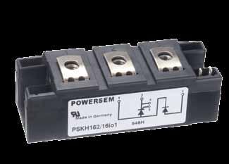
12 Thyristor / Diode Modules, released, E DRM I T T c 180 C sine I TRMS I FRMS I TRMS I FRMS T J = 45 C T JM 10ms C mω C PSKH 26/08io PSKH 26/12io PSKH 26/14io PSKH 26/16io PSKH 44/08io PSKH 44/12io PSKH 44/14io PSKH 44/16io PSKH 44/18io PSKH 56/08io PSKH 56/12io PSKH 56/14io PSKH 56/16io PSKH 56/18io PSKH 72/08io PSKH 72/12io PSKH 72/14io PSKH 72/16io PSKH 72/18io PSKH 94/20io PSKH 94/22io PSKH 95/08io PSKH 95/12io PSKH 95/14io PSKH 95/16io PSKH 95/18io PSKH 132/08io PSKH 132/12io PSKH 132/14io PSKH 132/16io PSKH 132/18io PSKH 161/20io PSKH 161/22io PSKH 162/08io PSKH 162/12io PSKH 162/14io PSKH 162/16io PSKH 162/18io PSKH 220/08io PSKH 220/12io PSKH 220/14io PSKH 220/16io PSKH 225/12io PSKH 225/14io PSKH 225/16io PSKH 225/18io PSKH 250/08io PSKH 250/12io PSKH 250/14io PSKH 250/16io PSKH 255/12io PSKH 255/14io PSKH 255/16io PSKH 255/18io PSKH 310/08io PSKH 310/12io PSKH 310/14io PSKH 310/16io PSKH 312/12io PSKH 312/14io PSKH 312/16io PSKH 312/18io TO T JM Chip Chip io1 io8 7 page 41 8 page 41 9 page page POWERSEM ll rights reserved
13 Thyristor Modules, released, E DRM I T I TSM TO 45 C 10ms Chip C mω C PST 70/ PST 70/ PST 70/ PST 70/ PST 90/ PST 90/ PST 90/ PST 90/ PST 160/ PST 160/ PST 160/ PST 160/ PSWT 70/ PSWT 70/ PSWT 70/ PSWT 70/ PSWT 90/ PSWT 90/ PSWT 90/ PSWT 90/ PSWT 160/ PSWT 160/ PSWT 160/ PSWT 160/ T JM Chip Chip PSWT/ PST 70/90/160 = isolated base PSXT/ PSYT 70/90/160 = non isolated base 2 page 38 POWERSEM ll rights reserved 13
14 Thyristor Modules, released, E Eco-Pac TM 2 I TRMS I FRMS I T I FM I FSM 45 C 10ms T J= T JM C mω C PSKH 80/ / / PSKH 80/ PSKH 80/ PSKC 96/ / / PSKC 96/ PSKC 96/ PSKC 96/ PSKC 96/ PSKC 96/ PSK 96/ / / PSK 96/ PSK 96/ PSK 96/ PSK 96/ PSK 96/ PSKH 96/ / / PSKH 96/ PSKH 96/ PSKH 96/ PSKH 96/ PSKH 96/ PSKT 96/ / / PSKT 96/ PSKT 96/ PSKT 96/ PSKT 96/ PSKT 96/ PSKI 96/ / / PSKI 96/ PSKI 96/ PSKI 96/ PSKI 96/ PSKI 96/ PSET 132/ / / PSET 132/ for 10 s PSET 132/ PSET 132/ PSET 132/ PSET 180/ / / PSET 180/ for 10 s PSET 180/ PSET 180/ PSET 180/ TO T JM Chip/ Module Chip/ Module 96 4 page POWERSEM ll rights reserved

15 Thyristor Modules, released, E DRM I T T c 180 C sine I TRMS I FRMS T J = T JM I TRMS I FRMS 45 C 10ms C mω C PSKT 19/08io PSKT 19/12io PSKT 19/14io PSKT 19/16io PSKT 19/08io PSKT 19/12io PSKT 19/14io PSKT 19/16io PSKT 26/08io PSKT 26/12io PSKT 26/14io PSKT 26/16io PSKT 26/08io PSKT 26/12io PSKT 26/14io PSKT 26/16io PSKT 44/08io PSKT 44/12io PSKT 44/14io PSKT 44/16io PSKT 44/18io PSKT 44/08io PSKT 44/12io PSKT 44/14io PSKT 44/16io PSKT 44/18io PSKT 56/08io PSKT 56/12io PSKT 56/14io PSKT 56/16io PSKT 56/18io PSKT 56/08io PSKT 56/12io PSKT 56/14io PSKT 56/16io PSKT 56/18io PSKT 72/08io PSKT 72/12io PSKT 72/14io PSKT 72/16io PSKT 72/18io PSKT 72/08io PSKT 72/12io PSKT 72/14io PSKT 72/16io PSKT 72/18io PSKT 94/20io PSKT 94/22io PSKT 95/08io PSKT 95/12io PSKT 95/14io PSKT 95/16io PSKT 95/18io PSKT 95/08io PSKT 95/12io PSKT 95/14io PSKT 95/16io PSKT 95/18io TO T JM Chip Chip io1 io8 7 page 41 POWERSEM ll rights reserved 15

16 Thyristor Modules, released, E DRM I T T c 180 C sine I TRMS I FRMS T J = T JM I TRMS I FRMS 45 C 10ms C mω C PSKT 132/08io PSKT 132/12io PSKT 132/14io PSKT 132/16io PSKT 132/18io PSKT 161/20io PSKT 161/22io PSKT 162/08io PSKT 162/12io PSKT 162/14io PSKT 162/16io PSKT 162/18io PSKT 170/12io PSKT 170/14io PSKT 170/16io PSKT 170/18io PSKT 220/08io PSKT 220/12io PSKT 220/14io PSKT 220/16io PSKT 224/20io PSKT 224/22io PSKT 225/12io PSKT 225/14io PSKT 225/16io PSKT 225/18io PSKT 250/08io PSKT 250/12io PSKT 250/14io PSKT 250/16io PSKT 250/18io PSKT 255/12io PSKT 255/14io PSKT 255/16io PSKT 255/18io PSKT 310/08io PSKT 310/12io PSKT 310/14io PSKT 310/16io PSKT 310/18io PSKT 312/12io PSKT 312/14io PSKT 312/16io PSKT 312/18io TO T JM Chip Chip io1 8 page 41 9 page page POWERSEM ll rights reserved
17 Single Phase Rectifier Bridges, released, E mm I D I FSM TO vrms 45 C Chip/ Chip/ 10ms Module Module C mω C PSB 15/ / / B2U PSB 15/ PSB 15/ PSB 21/ / / PSB 21/ PSB 25T/ / / B2U PSB 25T/ PSB 25T/ page 38 PSB 25T/ PSB 25T/ PSB 31/ / / PSB 31/ PSB 31/ PSB 31/16 PSB 31/ page 39 PSB 35T/ / / PSB 35T/ PSB 35T/ PSB 35T/ PSB 35T/ page 40 PSB 36T/ / / PSB 36T/ PSB 36T/ PSB 36T/ PSB 36T/18 PSB 41/08 PSB 41/ / / page 40 PSB 41/ PSB 41/ PSB 41/ PSB 50/ / / PSB 50/12 PSB 50/14 PSB 50/ page 43 PSB 50/ PSB 51/ / / PSB 51/ PSB 51/14 PSB 51/16 PSB 51/ page 43 PSB 53/ / / PSB 53/ PSB 53/ PSB 53/ PSB 54/08 PSB 54/ / / page 44 PSB 54/ PSB 54/ PSB 55T/ / / PSB 55T/ PSB 55T/14 PSB 55T/ page 44 PSB 55T/ PSB 61/ / / PSB 61/ PSB 61/ PSB 61/ page 49 PSB 61/ PSB 62/ / / PSBS 62/08 23 PSB 62/ PSBS 62/12 PSB 62/ PSBS 62/14 PSB 62/ PSBS 62/16 PSB 62/ PSBS 62/18 T JM 17 mm POWERSEM ll rights reserved 17
18 Single Phase Rectifier Bridges, released, E mm 30 mm 30 mm 30 mm 30 mm 30 mm 18 I D I FSM TO vrms 45 C Chip/ Chip/ 10ms Module Module B2U C mω C PSB 63/ / / PSBS 63/08 23 PSB 63/ PSBS 63/12 PSB 63/ PSBS 63/14 PSB 63/ PSBS 63/16 PSB 63/ PSBS 63/18 PSB 68/ / / PSB 68/ PSB 68/ PSB 68/ PSB 75/ / / PSB 75/ page 38 PSB 75/ PSB 75/ PSB 75/ PSB 78/ / / PSB 78/12 PSB 78/ page 38 PSB 78/ PSB 82/ / / PSBS 82/08 23 PSB 82/ PSBS 82/12 PSB 82/ PSBS 82/14 PSB 82/ PSBS 82/16 PSB 82/ PSBS 82/18 PSB 83/ / / PSBS 83/08 23 PSB 83/ PSBS 83/12 PSB 83/ PSBS 83/14 PSB 83/ PSBS 83/16 PSB 83/ PSBS 83/18 PSB 88/ / / PSB 88/ PSB 88/ PSB 88/ / page 39 PSB 95/ / / PSB 95/ PSB 95/ PSB 95/ PSB 95/ / page 39 PSB 105/ / / PSB 105/ PSB 105/ PSB 105/ PSB 105/ / page 40 PSB 112/ / / PSBS 112/08 22 PSB 112/ PSBS 112/12 PSB 112/ PSBS 112/14 PSB 112/ PSBS 112/16 PSB 112/ PSBS 112/18 PSB 125/ / / PSB 125/ PSB 125/ PSB 125/ / page 45 PSB 125/ PSB 162/ / / PSBS 162/08 22 PSB 162/ PSBS 162/12 PSB 162/ PSBS 162/14 PSB 162/ PSBS 162/16 PSB 162/ PSBS 162/18 PSB 192/ / / PSBS 192/08 22 PSB 192/ PSBS 192/12 PSB 192/ PSBS 192/14 PSB 192/ PSBS 192/16 PSB 192/ PSBS 192/18 T JM 17 mm 17 mm 17 mm 17 mm 17 mm 17 mm POWERSEM ll rights reserved page 49 page 49 page 49 page 48 page 48 page 48
19 Single Phase Half Controlled Rectifier Bridges, released, E I D I FSM vrms 45 C Chip/ Chip/ 10ms Module Module C mω C PSBH 25/ / / PSBH 25/ PSBH 50/ / / PSBH 50/ PSBH 50/ PSBH 50/ PSBH 55/ / / PSBH 55/ PSBH 55/ PSBH 55/ PSBH 75/ / / PSBH 75/ PSBH 75/ PSBH 85/ / / PSBH 85/ PSBH 85/ PSBH 125/ / / PSBH 125/ PSBH 125/ PSBH 125/ TO T JM B2HK Single Phase Half Controlled Rectifier Bridges, released, E I D I FSM vrms 45 C Chip/ Chip/ 10ms Module Module C mω C PSBZ 36/ / / PSBZ 36/ PSBZ 36/ PSBZ 36/ PSBZ 50/ / / PSBZ 50/ PSBZ 50/ PSBZ 50/ PSBZ 55/ / / PSBZ 55/ PSBZ 55/ PSBZ 55/ PSBZ 75/ / / PSBZ 75/ PSBZ 75/ PSBZ 85/ / / PSBZ 85/ PSBZ 85/ PSBZ 125/ / / PSBZ 125/ PSBZ 125/ PSBZ 125/ TO T JM B2HZ 2 page 38 3 page 39 5 page 40 6 page 40 POWERSEM ll rights reserved 19
20 Single Phase Half Controlled Rectifier Bridges, released, E With Freewheeling Diode I D I FSM vrms 45 C Chip/ Chip/ 10ms Module Module C mω C PSCH 25/ / / PSCH 25/ PSCH 50/ / / PSCH 50/ PSCH 50/ PSCH 50/ PSCH 55/ / / PSCH 55/ PSCH 55/ PSCH 55/ PSCH 75/ / / PSCH 75/ PSCH 75/14 PSCH 85/ / / PSCH 85/ PSCH 85/ PSCH 125/ / / PSCH 125/ PSCH 125/ PSCH 125/ TO T JM B2HKF Single Phase Full Controlled Rectifier Bridges, released, E I D I FSM vrms 45 C Chip/ Chip/ 10ms Module Module C mω C PSBT 25/ / / PSBT 25/ PSBT 50/ / / PSBT 50/ PSBT 50/ PSBT 50/ PSBT 55/ / / PSBT 55/ PSBT 55/ PSBT 55/ PSBT 75/ / / PSBT 75/ PSBT 75/ PSBT 85/ / / PSBT 85/ PSBT 85/ PSBT 125/ / / PSBT 125/ PSBT 125/ PSBT 125/ TO T JM B2C 2 page 38 3 page 39 5 page 40 6 page POWERSEM ll rights reserved
21 Single Phase Full Controlled Rectifier Bridges, released, E With Freewheeling Diode I D I FSM vrms 45 C Chip/ Chip/ 10ms Module Module C mω C PSCT 50/ / / PSCT 50/ PSCT 50/ PSCT 50/ PSCT 55/ / / PSCT 55/ PSCT 55/ PSCT 55/ PSCT 75/ / / PSCT 75/ PSCT 75/ PSCT 85/ / / PSCT 85/ PSCT 85/ PSCT 125/ / / PSCT 125/ PSCT 125/ PSCT 125/ TO T JM B2CF 2 page 38 5 page 40 6 page 40 Single Phase Full Controlled Rectifier Bridges, released, E With Fast Recovery Epitaxial Diodes I D I FSM vrms 45 C Chip/ Chip/ 10ms Module Module C mω ns PSB 19F/ / / PSB 19F/ / / 0.7 PSB 19F/ / / 0.7 PSB 19F/ / / 0.7 PSB 33F/ / / PSB 33F/ / / 0.48 PSB 33F/ / / 0.48 PSB 33F/ / / 0.48 PSB 71F/ / / PSB 71F/ / / 0.3 PSB 71F/ / / 0.3 PSB 71F/ / / 0.3 PSB 100F/ / / PSB 100F/ / / 0.25 PSB 100F/ / / 0.25 PSB 100F/ / / 0.25 TO t rr B2U 3 page 39 4 page 39 POWERSEM ll rights reserved 21
22 Three Phase Rectifier Bridges, released, E mm 30 mm I D I FSM TO vrms 45 C Chip/ Chip/ 10ms Module Module B6U C mω C PSD 25T/ / / PSD 25T/ PSD 25T/ PSD 25T/ PSD 25T/ page 38 PSD 27/ / / PSD 27/ PSD 27/ PSD 28/ / / PSD 28/ PSD 28/ page 39 PSD 31/ / / PSD 31/ PSD 31/ PSD 31/ PSD 31/ page 40 PSD 35T/ / / PSD 35T/ PSD 35T/ PSD 35T/ PSD 35T/18 PSD 36T/ / / page 40 PSD 36T/ PSD 36T/ PSD 36T/ PSD 36T/ PSD 41/ / / PSD 41/ page 43 PSD 41/ PSD 41/ PSD 41/ PSD 50/ / / PSD 50/ PSD 50/14 PSD 50/ page 43 PSD 50/ PSD 51/ / / PSD 51/ PSD 51/ PSD 51/16 PSD 51/ page 44 PSD 55T/ / / PSD 55T/ PSD 55T/ PSD 55T/ page 44 PSD 55T/ PSD 61/ / / PSD 61/ PSD 61/ PSD 61/ page 49 PSD 61/ PSD 62/ / / PSDS 62/08 23 PSD 62/ PSDS 62/12 PSD 62/ PSDS 62/14 PSD 62/ PSDS 62/16 PSD 62/ PSDS 62/18 PSD 63/ / / PSDS 63/08 23 PSD 63/ PSDS 63/12 PSD 63/ PSDS 63/14 PSD 63/ PSDS 63/16 PSD 63/ PSDS 63/18 T JM 17 mm 17 mm 22 POWERSEM ll rights reserved
23 Three Phase Rectifier Bridges, released, E mm 30 mm Solder Pin ersion 30 mm 30 mm 30 mm vrms I D C I FSM 45 C 10ms TO mω T JM C Chip/ Module Chip/ Module B6U PSD 67/ / / PSD 67/ PSD 67/ PSD 67/ / page 38 PSD 67/ PSD 68/ / / PSD 68/ PSD 68/ PSD 68/ PSD 68/ / page 39 PSD 75/ / / PSD 75/ PSD 75/ PSD 75/ / page 45 PSD 75/ PSD 82/ / / PSDS 82/08 23 PSD 82/ PSDS 82/12 PSD 82/ PSDS 82/14 PSD 82/ PSDS 82/16 PSD 82/ PSDS 82/18 PSD 83/ / / PSDS 83/08 23 PSD 83/ PSDS 83/12 PSD 83/ PSDS 83/14 PSD 83/ PSDS 83/16 PSD 83/ PSDS 83/18 PSD 86/ / / mm 17 mm Press Pin ersion PSD 86P9/06 24* PSD 86/ PSD 86P9/08 PSD 86/ PSD 86P9/12 PSD 86/ PSD 86P9/14 PSD 86/ PSD 86P9/16 PSD 95/ / / PSD 95/ * 17 mm Height PSD 95/ PSD 86P17/06 PSD 95/ PSD 86P17/08 PSD 95/ PSD 86P17/12 PSD 98/ / / PSD 86P17/14 PSD 98/ PSD 86P17/16 PSD 98/ PSD 98/ PSD 105/ / / PSD 105/ PSD 105/ / page 48 PSD 105/ PSD 105/ PSD 108/ / / PSD 108/ PSD 108/ / page 49 PSD 108/ PSD 112/ / / PSDS 112/08 22 PSD 112/ PSDS 112/12 PSD 112/ PSDS 112/14 PSD 112/ PSDS 112/16 PSD 112/ PSDS 112/18 PSD 125/ / / PSD 125/ PSD 125/ PSD 125/ / page 49 PSD 125/ PSD 162/ / / PSDS 162/08 22 PSD 162/ PSDS 162/12 PSD 162/ PSDS 162/14 PSD 162/ PSDS 162/16 PSD 162/ PSDS 162/18 PSD 192/ / / PSDS 192/08 22 PSD 192/ PSDS 192/12 PSD 192/ PSDS 192/14 PSD 192/ PSDS 192/16 PSD 192/ PSDS 192/18 17 mm 17 mm 17 mm 25 / page 50 POWERSEM ll rights reserved 23

24 Three Phase Half Controlled Rectifier Bridges, released, E vrms I D C I FSM 45 C 10ms TO mω T JM C Chip/ Module Chip/ Module PSDH 39/ / / PSDH 39/ PSDH 70/ / / PSDH 70/ PSDH 70/ PSDH 70/ PSDH 75/ / / PSDH 75/ PSDH 75/ PSDH 75/ PSDH 90/ / / PSDH 90/ PSDH 90/ PSDH 110/ / / PSDH 110/ PSDH 110/ PSDH 175/ / / PSDH 175/ PSDH 175/ PSDH 175/ B6HK Three Phase Half Controlled Rectifier Bridges, released, E With Freewheeling Diode vrms I D C I FSM 45 C 10ms TO mω T JM C Chip/ Module Chip/ Module PSFH 70/ / / PSFH 70/ PSFH 70/ PSFH 70/ B6HKF Three Phase Full Controlled Rectifier Bridges, released, E vrms I D C I FSM 45 C 10ms TO mω T JM C Chip/ Module Chip/ Module PSDT 39/ / / PSDT 39/ PSDT 70/ / / PSDT 70/ PSDT 70/ PSDT 70/ B6C 2 page 38 3 page 39 5 page 40 6 page POWERSEM ll rights reserved

25 Three Phase Full Controlled Rectifier Bridges, released, E vrms I D C I FSM 45 C 10ms TO mω T JM C Chip/ Module Chip/ Module PSDT 75/ / / PSDT 75/ PSDT 75/ PSDT 75/ PSDT 90/ / / PSDT 90/ PSDT 90/ PSDT 110/ / / PSDT 110/ PSDT 110/ PSDT 175/ / / PSDT 175/ PSDT 175/ PSDT 175/ B6C Three Phase Full Controlled Rectifier Bridges, released, E With Freewheeling Diode vrms I D C I FSM 45 C 10ms TO mω T JM C Chip/ Module Chip/ Module PSFT 70/ / / PSFT 70/ PSFT 70/ PSFT 70/ B6CF Three Phase Rectifier Bridges, released, E With Fast Recovery Epitaxial Diodes vrms I D C I FSM 45 C 10ms TO mω t rr ns Chip/ Module Chip/ Module PSD 24F/ / / PSD 24F/ / / 0.47 PSD 24F/ / / 0.47 PSD 24F/ / / 0.47 PSD 43F/ / / PSD 43F/ / / 0.32 PSD 43F/ / / 0.32 PSD 43F/ / / 0.32 PSD 91F/ / / PSD 91F/ / / 0.2 PSD 91F/ / / 0.2 PSD 91F/ / / 0.2 PSD 150F/ / / PSD 150F/ / / 0.17 PSD 150F/ / / 0.17 PSD 150F/ / / 0.17 B6U 2 page 38 3 page 39 4 page 39 5 page 40 6 page 40 POWERSEM ll rights reserved 25


26 Single Phase C Controller Modules, released, E , W1H, W1C I RMS I TMS I T l 2 45 C 10s 45 C Chip/ Chip/ 85 C 85 C 10ms 10ms Module Module mω C 2 s PSW1H 110/ / / PSW1H 110/ PSW1H 110/ PSW1H 140/ / / PSW1H 140/ PSW1H 140/ PSW1H 140/ PSW1H 140/ PSW1H 175/ / / PSW1H 175/ PSW1H 175/ PSW1H 175/ PSW1H 175/ PSW1H 205/ / / PSW1H 205/ PSW1H 205/ PSW1H 205/ PSW1H 205/ PSW1C 25/ / / PSW1C 25/ PSW1C 25/ PSW1C 40/ / / PSW1C 40/ PSW1C 40/ PSW1C 40/ PSW1C 40/ PSW1C 70/ / / PSW1C 70/ PSW1C 70/ PSW1C 100/ / / PSW1C 100/ PSW1C 100/ PSW1C 100/ PSW1C 100/ PSW1C 110/ / / PSW1C 110/ PSW1C 110/ PSW1C 140/ / / PSW1C 140/ PSW1C 140/ PSW1C 140/ PSW1C 140/ PSW1C 175/ / / PSW1C 175/ PSW1C 175/ PSW1C 175/ PSW1C 175/ PSW1C 205/ / / PSW1C 205/ PSW1C 205/ PSW1C 205/ PSW1C 205/ TO T JM PSW1H PSW1C110 PSW1C140 PSW1C175 PSW1C205 PSW1C25 PSW1C40 PSW1C70 PSW1C100 3 page 39 4 page POWERSEM ll rights reserved


27 Single Phase C Controller Subassemblies, released, E I RMS I FMS I T l 2 45 C 10s 45 C Chip/ 85 C 85 C 10ms 10ms Module mω C 2 s PSW1C 50/ / PSW1C 50/ PSW1C 50/ PSW1C 50/ PSW1C 75/ / PSW1C 75/ PSW1C 75/ PSW1C 112/ / PSW1C 112/ PSW1C 112/ PSW1C 142/ / PSW1C 142/ PSW1C 142/ PSW1C 142/ PSW1C 142/ PSW1C 176/ / PSW1C 176/ PSW1C 176/ PSW1C 176/ PSW1C 176/ PSW1C 206/ / PSW1C 206/ PSW1C 206/ PSW1C 206/ PSW1C 206/ TO T JM W1C 16 page page page page 47 Three Phase C Controller Subassemblies, released, E I RMS I FMS I T TO l 2 45 C 10s 45 C Chip/ 85 C 85 C 10ms 10ms Module mω C 2 s PSW3C 95/ / PSW3C 95/ PSW3C 95/ PSW3C 95/ T JM W3C 20 page 47 POWERSEM ll rights reserved 27

28 Three Phase C Controller Modules, released, E , W3H I RMS I TMS TO I T 45 C 10s Chip/ Chip/ 85 C 85 C 10ms Module Module mω C PSUH 35/ x / / PSUH 35/ PSUH 36/ x / / PSUH 36/ PSUH 36/ PSUH 36/ PSUH 40/ x / / PSUH 40/ PSUH 40/ PSUH 40/ PSUH 50/ x / / PSUH 50/ PSUH 50/ PSUH 50/ PSUH 60/ x / / PSUH 60/ PSUH 60/ PSUH 60/ PSUH 80/ x / / PSUH 80/ PSUH 80/ PSUH 95/ x / / PSUH 95/ PSUH 95/ T JM 3 page 39 6 page page 48 Three Phase C Controller Modules, released, E , W3C I T I RMS I TMS TO T JM 45 C 10s Chip/ Chip/ 85 C 85 C 10ms Module Module mω C PSUT 35/ x / / PSUT 35/ PSUT 36/ x / / PSUT 36/ PSUT 36/ PSUT 36/ PSUT 40/ x / / PSUT 40/ PSUT 40/ PSUT 40/ PSUT 50/ x / / PSUT 50/ PSUT 50/ PSUT 50/ PSUT 60/ x / / PSUT 60/ PSUT 60/ PSUT 60/ PSUT 80/ x / / PSUT 80/ PSUT 80/ PSUT 95/ x / / PSUT 95/ PSUT 95/ page 39 6 page page POWERSEM ll rights reserved
29 Rectifier Bridges for Power Factor Correction (PFC), Single Phase PFC released, E Boost Module with Ultra Fast IGBT and Boost Diode, Fast Recovery Diodes CES I C80 I F80 RMM I C80 T C IGBT boost diode rectifier 80 C 80 C 80 C diode IGBT boost rect. diode diodes PSBI 9/ PSBI 33/ Rectifier Bridges for Power Factor Correction (PFC), Single Phase PFC released, E Boost Module with MOSFET and Boost Diode, Fast Rectifier Diodes DSS max. I D(cont.) T s 25 C R DS(on) 80 C boost diode Ω PSBM 24/ R thjs max. P D max. TS= 25 C boost diode rectifier diode 3 page 39 4 page 39 POWERSEM ll rights reserved 29
30 Trench Gate IGBT Modules, released, E ECO-PC TM 1 CES oltage Grade I C Current 75 C I CM Maximum Current Raiting CE (ST) Saturation oltage (Typical) E TS Total Switching Energy iso Isolation oltage IGBT Chip diode Chip mj mω KW KW PSTG 25 HDT ,9 4 3,0 1,1 4,0 3 PSTG 25 HDT ,9 4 3,0 1,1 4,0 PSTG 25 HDT ,9 4 3,0 1,1 4,0 PSTG 25 HTT ,9 4 3,0 1,1 4,0 3 PSTG 25 HTT ,9 4 3,0 1,1 4,0 PSTG 25 HTT ,9 4 3,0 1,1 4,0 PSTG 50 HST ,9 8 3,0 0,83 2,0 3 PSTG 50 HST ,9 8 3,0 0,83 2,0 PSTG 50 HST ,9 8 3,0 0,83 2,0 PSTG 75 HST ,9 12 3,0 0,55 1,33 3 PSTG 75 HST ,9 12 3,0 0,55 1,33 PSTG 75 HST ,9 12 3,0 0,55 1,33 Circuit configurations for the Trench Gate IGBT Modules PSTG 25 HDT Half-Bridge PSTG 50 HST Single Switch PSTG 25 HTT Triple Switch PSTG 75 HST Single Switch 3 page POWERSEM ll rights reserved

31 IGBT Modules, released, E ECO-PC TM 2 IGBT Module (H-bridge configuration) CES oltage Grade I C25 25 C I F80 80 C CE (ST) Saturation oltage (typical) T j =25 C E off T j =25 C IGBT IGBT IGBT IGBT mj PSHI 25/06* PSHI 25/12* PSHI 50/06* PSHI 50/12* PSHI 100/06* *NTC optional I F25 Tc= 25 C Diode I F80 Tc= 80 C Diode 4 page 39 IGBT Modules, released, E ECO-PC TM 2 IGBT Module (H-bridge configuration) CES I C25 I F80 CE (ST) oltage T IGBT Tc= 25 C Tc= 80 C C Saturation T j =25 C Grade 25 C 80 C oltage IGBT Diode Diode Type IGBT IGBT (typical) Tc= 25 C Tc= 80 C IGBT IGBT T j =25 C IGBT IGBT Diode Diode mj PSHI 50D/06* PSHI 50D/12* PSHI 75D/06* *NTC optional E off I F25 I F80 4 page 39 IGBT Modules, released, E ECO-PC TM 2 IGBT Module (Phase-leg configuration) CES oltage Grade I C25 25 C I F80 80 C CE (ST) Saturation oltage (typical) T j =25 C t d(on) t d(off) delay time Switching Caracteristics ns IGBT IGBT IGBT Diode PSI 25/06* PSI 25/12* PSI 50/06* PSI 50/12* PSI 75/06* PSI 75/12* PSI 100/06* PSI 130/06* *NTC optional I F25 Tc= 25 C Diode I F80 Tc= 80 C Diode 4 page 39 POWERSEM ll rights reserved 31
32 IGBT Modules, released, E ECO-PC TM 2 IGBT Module (boost chop) CES oltage Grade I C25 25 C I F80 80 C CE (ST) Saturation oltage (typical) T j =25 C t d(on) t d(off) Delay Time Switching Characteristics ns IGBT IGBT IGBT Diode PSSI 25/06* PSSI 25/12* PSSI 50/06* PSSI 50/12* PSSI 75/06* PSSI 75/12* PSSI 100/06* PSSI 100/12* PSSI 130/06* PSSI 160/12* *NTC optional I F25 Tc= 25 C Diode I F80 Tc= 80 C Diode IGBT Modules, released, E ECO-PC TM 2 IGBT Module CES oltage Grade I C25 25 C I F80 80 C CE (ST) Saturation oltage (typical) T j =25 C t d(on) t d(off) Delay Time Switching Characteristics ns IGBT IGBT IGBT Diode PSSI 45D/ PSSI 46D/ I F25 Tc= 25 C Diode I F80 Tc= 80 C Diode 45D 46D IGBT Modules, released, E ECO-PC TM 2 IGBT Module (buck chop) CES oltage Grade I C25 25 C I F80 80 C CE (ST) Saturation oltage (typical) T j =25 C t d(on) t d(off) Delay Time Switching Characteristics ns IGBT IGBT IGBT Diode PSIS 25/06* PSIS 25/12* PSIS 50/06* PSIS 50/12* PSIS 75/06* PSIS 75/12* PSIS 100/06* PSIS 100/12* PSIS 130/06* PSIS 160/12* *NTC optional I F25 Tc= 25 C Diode I F80 Tc= 80 C Diode 4 page POWERSEM ll rights reserved


33 IGBT Modules, released, E ECO-PC TM 2 IGBT Sixpac Module CES oltage Grade I C25 25 C I F80 80 C CE (ST) Saturation oltage (typical) T j =25 C E off T j =25 C IGBT IGBT IGBT IGBT mj PSII 6/12* PSII 15/12* PSIIX 20/ PSII 24/06* PSII 35/ *NTC optional I F25 T c = 25 C Diode I F80 T c = 80 C Diode IGBT Modules, released, E ECO-PC TM 1 IGBT Sixpac Module with NTC CES I C25 I C80 CE (ST) E off I F25 I F80 oltage T C Saturation Tc= 25 C Tc= 80 C Grade 25 C 80 C oltage T j =25 C IGBT IGBT IGBT (typical) IGBT T j =25 C Diode Diode mj PSII 3x10/ IGBT Modules, released, E ECO-PC TM 1 STRT UP Module CES oltage Grade I C25 25 C I C80 80 C CE (ST) Saturation oltage (typical) T j =25 C t d(on) t d(off) Delay Time Switching Characteristics ns IGBT IGBT IGBT Diode Diode PSBI 30/ I F25 Tc= 25 C I F80 Tc= 80 C IGBT Modules, released, E ECO-PC TM 1 Chop Module CES oltage Grade I C25 25 C I C80 80 C CE (ST) Saturation oltage (typical) T j =25 C t d(on) t d(off) Delay Time Switching Characteristics ns IGBT IGBT IGBT Diode Diode PSIC 30/ I F25 Tc= 25 C I F80 Tc= 80 C 3 page 39 4 page 39 POWERSEM ll rights reserved 33
34 IGBT Modules, released, E ECO-PC TM 2 IGBT Module (single switch) CES oltage Grade I C25 25 C I F80 80 C CE (ST) Saturation oltage (typical) T j =25 C t d(on) t d(off) Delay Time Switching Characteristics ns IGBT IGBT IGBT Diode PSIG 25/ PSIG 25/ PSIG 50/ PSIG 50/ PSIG 75/ PSIG 75/ PSIG 100/ PSIG 100/ PSIG 130/ PSIG 160/ I F25 Tc= 25 C Diode I F80 Tc= 80 C Diode 4 page 39 Rectifier Bridges for Braking Systems, released, E ECO-PC TM 2 Three Phase Rectifier Bridge with IGBT and Fast Recovery Diode for Braking System Rectifier IGBT fast Diode I TH C CES I C80 IF () t rr ns PSDI 33/06* PSDI 50/ TC= *NTC optional 4 page 39 Rectifier Bridges for Braking Systems, released, E ECO-PC TM 2 Three Phase Rectifier Bridge with MOSFET and Fast Recovery Diode for Braking System Rectifier MOSFET fast Diode I TH C CES I C80 IF () t rr ns PSDM 33/05* *NTC optional 4 page POWERSEM ll rights reserved
35 DSS I D25 T s =25 C I D80 T s =28 C mω ns ns PSHM 40/06* ( =90 C) PSHM 120/01* PSHM 140/01* TBD TBD *NTC optional R DS(on) T j =25 C t f t r MOSFET Modules, released, E ECO-PC TM 2 Forward Converter DSS I D25 T s =25 C I D80 T s =28 C mω ns ns PSHM 40D/06* (TC=90 C) PSHM 120D/01* PSHM 140D/01* TBD TBD *NTC optional R DS(on) T j =25 C t f t r MOSFET Modules, released, E ECO-PC TM 2 DSS I D25 T s =25 C I D80 T s =28 C mω ns ns PSMI 40/06* (TC=90 C) *NTC optional R DS(on) T j =25 C t f t r MOSFET Modules, released, E ECO-PC TM 2 DSS I D25 T s =25 C I D80 T s =28 C mω ns ns PSMG 50/05* PSMG 60/ tbd PSMG 100/05* PSMG 150/01* *NTC optional R DS(on) T j =25 C t f t r 4 page 39 POWERSEM ll rights reserved 35

36 Stud Type Devices Standard Recovery Diodes () I F() () F () I FSM () I R (µ) R th (j-c) ( o C/W) PSM DO-4 PSM DO-4 PSM DO-4 PSM DO-5 PSM DO-5 PSM DO-5 PSM DO-5 PSM DO-5 PSM DO-8 PSM DO-8 PSM DO-8 PSM DO-8 PSM DO-9 PSM DO-9 PSM DO-9 PSM DO-9 Fast Recovery Diodes () I F() () F () Package PSM 12F DO-4 PSM 16F DO-4 PSM 25F DO-5 PSM 40F DO-5 PSM 70F DO-5 I FSM () I R (µ) R th (j-c) ( o C/W) t rr (ns) Package Schottky Diodes () I F() () F () I FSM () R th (j-c) ( o C/W) Package PSM 1N DO-4 PSM 1N DO-5 PSM 1N DO-5 PSM 1N DO-5 PSM 1N DO-4 PSM SD DO-4 PSM SD DO-5 Zener Diodes Zener oltage () Wattage (W) F () I () Package PSM 1N2970 PSM 1N DO-4 PSM BZY93 Series DO-4 PSM 1N3305 PSM 1N DO-5 PSM BZY91 Series DO-5 Thyristors () I T() () TM () I TSM () PSM 25NT TO-48 PSM 40NT TO-65 PSM 56NT TO-65 PSM 70NT TO-94 PSM 100NT TO-94 PSM 125NT TO-94 PSM 150NT TO-93 GT () I GT (m) dv/dt (/µs) R th (j-c) ( o C/W) Package For detailed information with pictures, outlines and datasheets visit 36 POWERSEM ll rights reserved
37 Mounting Instructions Modules and Rectifier Bridges: Contact surfaces must be free of dirt and be undamaged. The heat sink contact surface must have a flatness of < 0.03 mm (< 1.2 mil) and a levelling depth of <0.02 mm (< 0.8 mil). pply a thin layer of heat transfer paste evenly to the module s base plate just sufficient to cover the entire base plate. It is recommended to apply DC 340 (Dow Corning) or Berulub FZ 1E3 (Bechem, silicone free), or equivalent by using a sponge/soft rubber roller. The minimum thickness of grease is best controlled by removing some modules from the heat sink after mounting and inspecting the entire area of the metal base plate. The module bottom surface must have wetted completely with thermal grease. The minimum required depth of thread in aluminium heatsinks is 12 mm and 10 mm in cop heat sink. ll mounting holes must be free from burrs. First tighten all mounting and terminal screws stepwise. Then use a torque wrench to apply the tightening torques given on the data sheet. Make sure that the screws fit easily into the threads. Otherwise the total tightening torque will be reached without the necessary contact being obtained. Do not pull or push on the terminals when making the electrical connections. Make sure that no manent tensile force is exerted on the terminals. Modules and Rectifier Bridges supplied with solderable leads: The maximum allowable soldering time is 10 seconds. Do not exert any axial force on the leads. Make sure that the distance between the bending axis and package is > 5 mm, with the bending radius > 2 mm. void repeated bending. The distance between solder leads and package should be > 10 mm. Note about Modules with Cop-Baseplates: Due to the manufacturing process there could be variations in the flatness of the baseplates. But the thermal resistance will always be within the limits of the datasheets. The flatness is controlled in several steps during the manufacturing process. Make sure that the given torque is not exceeded. Besides a thermal conductance paste (e.g. DC 340, Dow Corning) has to be used with a layer thickness of 50µm -100µm. Important note: The terminal connection torques given in the data sheets are maximum values, depending on the applied connection. Using current bars, torques up to 5 Nm can be necessary to achieve a tight and reliable connection. For open cable lugs, a torque of 2.5 Nm is already sufficient to realize a good electrical connection. Higher terminal connection torques could damage the lug itself as well as the module terminals and the housing. In every case, one should pay attention, that the clamping parts don t move, while the terminal screws are fastened. Twisting of the terminals would effect mechanical stresses on the terminals themselves and on the housing. Both could reduce lifetime and reliability fo the module. For each module you can download detailed datasheets from our website or send us your request to datasheets@powersem.com if you should need more help and information concerning mounting instructions do not hesitate to contact: tech@powersem.com POWERSEM ll rights reserved 37
 1, 30 mm Height, 72 mm Length Picture only representative for Housing Dimensions 2, 30 mm Height, 94 mm Length Outline only representative for Housing Dimensions 2, 30 mm Height, 94 mm Length")
38 s Module Picture 1, 30 mm Height, 72 mm Length Outline Drawing Dimensions in mm (1mm = ) 1, 30 mm Height, 72 mm Length Picture only representative for Housing Dimensions 2, 30 mm Height, 94 mm Length Outline only representative for Housing Dimensions 2, 30 mm Height, 94 mm Length Picture only representative for Housing Dimensions Outline only representative for Housing Dimensions 38 POWERSEM ll rights reserved
39 s Module Picture 3, ECO-PC TM 1, Solder ersion, Gold-Plated Outline Drawing Dimensions in mm (1mm = ) 3, ECO-PC TM 1, Solder ersion, Gold-Plated Picture only representative for Housing Dimensions Outline only representative for Housing Dimensions 4, ECO-PC TM 2, Solder ersion, Gold-Plated 4, ECO-PC TM 2, Solder ersion, Gold-Plated Picture only representative for Housing Dimensions Outline only representative for Housing Dimensions POWERSEM ll rights reserved 39


40 s Module Picture 5, POWER-PC TM, 17 mm Height Outline Drawing Dimensions in mm (1mm = ) 5, POWER-PC TM, 17 mm Height Picture only representative for Housing Dimensions Outline only representative for Housing Dimensions 6 6 Picture only representative for Housing Dimensions Outline only representative for Housing Dimensions 40 POWERSEM ll rights reserved


41 s Module Picture 7 7 Outline Drawing Dimensions in mm (1mm = ) Picture only representative for Housing Dimensions Outline only representative for Housing Dimensions 8 8 Picture only representative for Housing Dimensions Outline only representative for Housing Dimensions POWERSEM ll rights reserved 41


42 s Module Picture 9 9 Outline Drawing Dimensions in mm (1mm = ) Picture only representative for Housing Dimensions Outline only representative for Housing Dimensions Picture only representative for Housing Dimensions Outline only representative for Housing Dimensions 42 POWERSEM ll rights reserved
 Picture only representative for Housing Dimensions Outline only")

43 s Module Picture Outline Drawing Dimensions in mm (1mm = ) Picture only representative for Housing Dimensions Outline only representative for Housing Dimensions Picture only representative for Housing Dimensions Outline only representative for Housing Dimensions POWERSEM ll rights reserved 43
 Picture only representative for Housing Dimensions 14, 6 mm Height Outline only representative for Housing Dimensions 14, 6 mm Height Picture only representative")
44 s Module Picture Outline Drawing Dimensions in mm (1mm = ) Picture only representative for Housing Dimensions 14, 6 mm Height Outline only representative for Housing Dimensions 14, 6 mm Height Picture only representative for Housing Dimensions Outline only representative for Housing Dimensions 44 POWERSEM ll rights reserved
 Picture only representative for Housing Dimensions 16, SUB-SSEMBLY Outline only representative for Housing Dimensions 16, SUB-SSEMBLY Picture only representative")
45 s Module Picture Outline Drawing Dimensions in mm (1mm = ) Picture only representative for Housing Dimensions 16, SUB-SSEMBLY Outline only representative for Housing Dimensions 16, SUB-SSEMBLY Picture only representative for Housing Dimensions Outline only representative for Housing Dimensions POWERSEM ll rights reserved 45
 17, SUB-SSEMBLY Picture only representative for Housing Dimensions 18, SUB-SSEMBLY")

46 s Module Picture 17, SUB-SSEMBLY Outline Drawing Dimensions in mm (1mm = ) 17, SUB-SSEMBLY Picture only representative for Housing Dimensions 18, SUB-SSEMBLY Outline only representative for Housing Dimensions 18, SUB-SSEMBLY Picture only representative for Housing Dimensions Outline only representative for Housing Dimensions 46 POWERSEM ll rights reserved


47 s Module Picture 19, SUB-SSEMBLY Outline Drawing Dimensions in mm (1mm = ) 19, SUB-SSEMBLY Picture only representative for Housing Dimensions 20, SUB-SSEMBLY Outline only representative for Housing Dimensions 20, SUB-SSEMBLY Picture only representative for Housing Dimensions Outline only representative for Housing Dimensions POWERSEM ll rights reserved 47


48 s Module Picture 21, 17 mm Height Outline Drawing Dimensions in mm (1mm = ) 21, 17 mm Height Picture only representative for Housing Dimensions 22, 17 mm Height Outline only representative for Housing Dimensions 22, 17 mm Height Picture only representative for Housing Dimensions Outline only representative for Housing Dimensions 48 POWERSEM ll rights reserved
 23, 17 mm Height Picture only representative for Housing Dimensions Outline only")

49 s Module Picture 23, 17 mm Height Outline Drawing Dimensions in mm (1mm = ) 23, 17 mm Height Picture only representative for Housing Dimensions Outline only representative for Housing Dimensions 24, ECO-PRESS-FIT TM 24, ECO-PRESS-FIT TM Picture only representative for Housing Dimensions Outline only representative for Housing Dimensions POWERSEM ll rights reserved 49
 25, 17 mm Height, ECO-PRESS-FIT TM 25, 17 mm Height, ECO-PRESS-FIT TM Picture only representative for Housing Dimensions")
50 s Module Picture Outline Drawing Dimensions in mm (1mm = ) 25, 17 mm Height, ECO-PRESS-FIT TM 25, 17 mm Height, ECO-PRESS-FIT TM Picture only representative for Housing Dimensions Outline only representative for Housing Dimensions 50 POWERSEM ll rights reserved

51 POWER MODULES SiC at its Best! or Customer Specific SiC Modules While the speed of development for power electronics is increasing and possibilities of technology are exponentiating, today develos have various choice of which device to choose. The following article intends to get an overview for the various technologies and innovations in packaging technologies for customer specific SiC power modules. By C. Rocneanu, Field pplication Engineer, ME Elektronik Service GmbH nd Co-uthor: R. Dilsch, pplication Engineer, CeramTec GmbH The field of power electronics is aiming at three important goals: miniaturization of devices while increasing the power density and reducing the losses. In the past there have been different approaches to achieve those goals One approach is the use of different materials. Silicon replaced Germanium very quick and has been hold as "philosopher's stone" for a long time. With the wide band gap materials the revolution in the power electronic industry starts again. Due to the wide band gap as well as very good thermal conductivity SiC and GaN are ideal for high break down voltages, high frequencies and high temature oation. Due to the structure of cost (yield and $/cm²) and the figure of merit for GaN-HEMTs (High Electron Mobility Transistor) the expected domain of GaN devices will be in application with break down voltages below 1200, while the domain of SiC will be for break down voltages greater and equal to1200. [1] and blocking voltage. While the IGBT is generally used for low frequencies (<30kHz) and high blocking voltages (>1000) the MOS- FET is used for higher frequencies (>=20kHz) and lower blocking voltages (<400) In the overlap segments where MOSFET and IGBT can be used it depends on the customer's application. lso special developed FETs like the SJFET are dominant in this market segment. With introduction of SiC- and GaN-power devices the hunt for the best topology starts again. Today SiC-MOSFET, -JFET and -BJT are commercially available. Due to the good adaption to Si devices a trend can be seen for the MOSFET. CREE and other mayor vendors are going for the normally-off MOSFET. Other companies go for the JFET (mostly normallyon) because of its higher current capacity. The problem with the normally-on structure with the GaN-HEMT or the SiC-JFET can be solved by a series connection of a Low-oltage Si MOSFET (Cascode circuit). s another big player Fairchild is going with the BJT for the bipolar structure. lthough, the use of SiC-diodes and -transistors have made a big progress in some applications there are two more mayor problems to be solved before SiC can fully penetrate the market: pricing and package Compared with Si-power devices on a discrete Level the price device for SiC is multiples time higher. 1: Overview of different power semiconductors in different voltage classes for Si and SiC SiC- und GaN-power devices One further approach is the power device topology. Until the 1970s the bipolaransistor has been state of the art. Due to its voltage dependent behavior, positive temature coefficient and low conduction losses the MOSFET could replace the bipolar transistor. With the introduction of the IGBT in the 80s advantages of the bipolar and FET structure could be combined. Nowadays both MOSFET and IGBT have their oating area dependent on the intended frequency t the discrete component level, the price component part is higher compared to the Si power semiconductors due to the fact that the production is limited to 4" SiC wafers at the moment and SiC is a very expensive material. There will, however, be a significant improvement in terms of pricing in the medium term, because the surface of a SiC MOSFET is considerably smaller than an Si-IGBT and CREE e.g. can switch over to 6" wafers should the demand continue to increase. Upon introduction of a 1700, 1ohm SiC MOSFET (C2M D), CREE can even offer a MOSFET which, in terms of price, is able to keep up with the Si-MOSFETs with a reverse voltage of more than and has a significantly better formance. Furthermore, CREE, apart from the second generation of the 1200, 80mohm POWERSEM ll rights reserved 51


52 POWER MNGEMENT MOSFETs, has now also launched the second generation of the 1200, 160mohm MOSFETs (C2M D). In the second generation of SiC-MOSFETs, a considerably improved price could be achieved by a reduction of the chip area. Moreover, faster turn off and a better overall formance can be obtained by means of the expanded input voltage range ( GS =-10/ +25) and the lower capacitance. ll MOSFETs are available ex stock ME Elektronik Service GmbH. comparison of the price in relation to the overall system costs shows a considerable reduction of switching losses and a reduction of costs in certain applications. The advantages offered by the characteristics of the SiC technology such as the higher switching speeds or extremely low losses can e.g. lead to cost savings with regard to inductor or heat sink. Integrated circuit packaging part from the price, another significant item is the housing or more precisely the integrated circuit packaging. On the one hand, the market requires the adaptation of standard packages, in order to reduce time and effort and the costs of a design-in. On the other hand, the available packages are hardly appropriate for the requirements and possibilities of SiC and GaN due to insufficient heat dissipation. With identical RDS,on, a SiC-MOSFET has a 33 times, respectively 10 times smaller chip area than a Si-MOSFET or Si-SJFET. reduction of the chip surface also leads to a reduced gate charge Qg and overall capacitance C, which are substantial factors for the losses. Fig. 2 shows the development of the chip surfaces in the past years. 3: Selection of several Powersem packages with different overall heights. SiC- Eco TM 1 and SiC-Eco TM 2 9mm and 17mm overall height, SOT mm overall height, Subassembly variable overall height, SiC-Slim TM 6mm overall height, Eco-SMPD TM 5.5mm overall height, Eco-227 TM 12mm overall height without base plate, Chip-on-Heatsink TM (CoH) variable overall height "With the Eco-227 TM, we have responded to the customers' needs without losing sight of the significantly improved characteristics of the SiC chips" says Mr Chadda, Managing Director of Powersem GmbH. "Due to the same housing and mounting dimensions as with the SOT-227, the customer is provided with optimum adaptability without being forced to convert his production. Consideration is given to the chip by mounting the Eco-227 TM without additional base plate." Further examples are the SiC-Eco 1, SiC-Eco 2 and SiC-Eco 3 with a module overall height of 6mm, 9mm or 17mm. The SiC-Eco TM family is available both as solder able and as press-fit versions (Eco-Press- Fit TM ). The Eco-SMPD TM (see figure 3) is also completely new and, compared to conventional TO-247 oo-264 packages, it excels in low parasitic capacitances, low thermal resistance and high electrical voltage isolation. Furthermore, Powersem is able to use the "Chip-on-Heatsink TM " technology in its module concepts. "Chip-on-Heatsink TM " is an innovation by CeramTec GmbH. s a manufacturer of high-formance ceramics, CeramTec is an important supplier for the power electronics industry. In the Chip-on-Heatsink technique, a cop layer is applied and sintered onto a ceramic base plate. These techniques are well known e.g. from thick-film technology. Thus, the ceramic material replaces the former base plates made of cop or ISiC and provides the electrical isolation. The use of cop provides excellent electrical and thermal conductivity. The chip is directly soldered onto this cop layer. Due to this technique, a large number of thermal resistors can be omitted. Depending on the required ampacity and heat distribution, the cop layer may have a thickness of up to 400μm. Depending on the layout, the intimate bond between cop and ceramic material brings about a slightly convex bottom plate which is extremely beneficial for the heat-transmitting mounting on a heat sink. 2: Development of chip area with respect to junction temature in power electronics [2] Due to the fact that the ratio between power loss and available module surface steadily increases, the type of cooling (air, liquid) is another important element apart from the thermal transfer. arious packaging technologies and chip carrier substrates are now also available here. Powersem packages Since 2013, ME Elektronik Service GmbH has been cooating with Powersem GmbH, a German manufacturer and innovator of customized SiC modules. Chip on Heatsink offers fect preconditions for the reduction of the thermal resistance, in order to effectively distribute heat from the SiC chips. This feature as well as the thermal cycle-ability, which is about 10 times higher compared to the previous standard technologies, may lead to considerable improvements in power electronics. The base plate cannot only be designed as a flat plate but also as a heat sink with integrated fins for convection cooling. Due to the fact that the base plate and the fins consist of one part, the normally necessary thermal heat sink paste or soldering can be omitted. If even higher losses are dissipated, the use of ceramic material enables the design of highly efficient liquid coolers. Here, the cop layer is directly applied, too, and represents the conductive paths, onto which the dies are directly soldered or sintered without any further interface. 52 POWERSEM ll rights reserved


![Usual distributors are dependent on the 4: left-hand: DCB with double-sided cop [3], middle: cross section of SCT design with base plate or liquid cooler, right-hand: cross section of SCT design with](/docs-images/75/71579615/images/53-2.jpg "liquid cooler high thermal conductivity value indicates a higher heat transmission unit of time.")
53 POWER MODULES Substrate chart Nowadays, the three most commonly used substrates are L2O3, IN and Si3N4. part from the costs, the different physical proties such as thermal conductivity, thermal capacity, heat distribution and the coefficient of thermal expansion have to be taken into account. Table 1 shows an overview of the physical proties and a general cost overview for L2O3, IN and Si3N4. expansion of the thick-film technology towards considerably higher currents and formances. Summary It has been stated that not only the appropriate package is vital for the selection of the right module but above all the right selection of substrates and technology. Usual distributors are dependent on the 4: left-hand: DCB with double-sided cop [3], middle: cross section of SCT design with base plate or liquid cooler, right-hand: cross section of SCT design with liquid cooler high thermal conductivity value indicates a higher heat transmission unit of time. The breakdown voltage specifies which maximum field strength an insulating material can withstand under certain conditions without losing its insulating proties. The coefficient of thermal expansion describes the relative change of length in case of a change of temature. L 2 O 3 IN Si 3 N 4 Thermal C [W/mK] Breakdown voltage [K/mm] Coefficint of thermal C C [ppm/k] Costs Nov 2013 low high very high Table 1: Physical proties and cost appraisal of different substrates [2] While the cost appraisal in general clearly speaks in favor of L 2 O 3, ln and Si 3 N 4 have obvious technical advantages compared to L 2 O 3. The better thermal conductivity of ln compared to Si 3 N 4 may be put into spective taking into consideration that with Si 3 N 4 only substrate layers which are half as thick can be used. nother big advantage of Si 3 N 4 is the higher thermal stability against alternating loads. The thermal stability against alternating loads depends to a great extent on the technology applied. DCB, MB and SCT Direct cop bonded (DCB) or Direct Bond Cop (DBC) comprises the application of cop onto insulation (ceramic material) by means of a high-temature process, which very firmly bonds the cop to the ceramic material. The cop layers normally have a thickness of 200 or 300μm which makes fine structures impossible. Similar applies to MB, where a cop film is firmly bonded to a ceramic plate by means of a high-temature soldering process across the entire surface. Then the insulation trenches are etched in both processes. With SCT, the process is different. Here, the cop layer is applied onto a ceramic plate up to a thickness of 400μm, namely only where it is desired. Due to the processes applied, almost any thicknesses can be produced. Furthermore, not only ranges with thin and very fine structures (100μm pitch) but also ranges with thick cop with a high ampacity are possible on a substrate. Thus, SCT represents an existing technologies of their suppliers and have to sell their available product portfolio to the customers. s a design-in distributor, ME, however, strongly focuses on technical competence. ccordingly, well-known manufacturers are working on customized projects together with ME, thus guaranteeing that the customer is able to decisively contribute to the development of the desired module. DCB [cycles] MB [cycles] L 2 O 3 IN Si 3 N 4 Medium (can be improved by Dimple) Medium (can be improved by Dimple) SCT [cycles] ery good good Poor (can be ery improved by Dimple) good Poor (can be ery improved by Dimple) good ery good Table 2: Thermal stability against alternating loads with different substrates and technologies CREE Inc., Powersem GmbH and CeramTec GmbH are strong and innovative partners of ME Elektronik GmbH who fectly match the customized design-in strategy of ME Elektronik due to their exience and know-how. Should further information about this topic be desired, please do not hesitate to contact one of the following sons: Mr Chadda, Managing Director of Powersem GmbH, sic@powersem.com, Mr Dilsch, pplications Engineer, CeramTech GmbH, r.dilsch@ceramtec.de, Mr Rocneanu, pplications Engineer, ME Elektronik Service GmbH, power@mev-elektronik.com, Sources: [1] Michael. Briere, The Status of GaN-on-Si based Power Device Development at International Rectifier, COO Enterprises LLC under contract to International Rectifier, PEC Exhibitor Presentation, March 19, 2013 [2] [3] DCB image from POWERSEM ll rights reserved 53

54 Nuremberg, May POWERSEM ll rights reserved


55 RECTIFIER BRIDGES Current oltage vailable Configurations PSB 25MB & PSD 25MT PSB 25MBN & PSD 25MTN PSB 25T & PSD 25T PSB 25TN & PSD 25TN PSB 36MB & PSD 36MT PSB 36MBN & PSD 36MTN PSB 36T & PSD 36T PSB 36TN & PSD 36TN Highlights: > Single phase and three phase uncontrolled bridges > Compact package, easy to mount with one screw > Connectors suitable for easy PCB mounting > Gold plated or nickel plated terminals > UL certified, RoHS and RECH conform and Halogen-Free Nomenclature: TN 25 PSD dd ON T, MT, MB = Different chip categories, Gold Plated TN, MTN, MBN = Different chip categories, Nickel Plated Current Rating 25 = = 36 Device Type PSD Three Phase PSB Single Phase FULL CONTROLLED RECTIFIER BRIDGES Current oltage vailable Configurations PSBT 20 Highlights: > Single phase fully controlled bridge > Replaces 4 discrete thyristors > Reduced costs and assembly times > Compact package, easy to mount with one screw > Connectors suitable for easy PCB mounting > Nickel plated terminals > UL certified, RoHS and RECH conform and Halogen-Free 4x = POWERSEM ll rights reserved 55
56 56 POWERSEM ll rights reserved
57 POWERSEM ll rights reserved 57
58 58 POWERSEM ll rights reserved

59 POWERSEM ll rights reserved 59
Contents. MOSFET Chips V DSS. Bipolar Chips V RRM / V DRM. Direct Copper Bonded (DCB), Direct Alu Bonded (DAB) Ceramic Substrates.
, Direct Alu Bonded (DAB) Ceramic Substrates.") Contents Page Symbols and Definitions 2 Nomenclature 2 General Information 3 Assembly Instructions 4 FRED, Rectifier Diode and Thyristor Chips in Planar Design 5 IGBT Chips V CES G-Series, Low V CE(sat)
Contents Page Symbols and Definitions 2 Nomenclature 2 General Information 3 Assembly Instructions 4 FRED, Rectifier Diode and Thyristor Chips in Planar Design 5 IGBT Chips V CES G-Series, Low V CE(sat)
2-1. Terms and Characteristics. Description of Terms Cooling Performance of the Automotive IGBT Module
 Chapter 2 Terms and Characteristics 1. 2. Description of Terms Cooling Performance of the Automotive IGBT Module 2-5 2-2 2-1 This chapter describes the terms related to the automotive IGBT module and its
Rectifier Diodes - Stud Types
 Rectifier Diodes - Stud Types Westcode's rectifier devices are designed to survive even the most arduous of applications. These highly reliable components are suitable for all rectifier applications, including
LSIC1MO120E V N-channel, Enhancement-mode SiC MOSFET
 LSIC1MO120E0160 1200 N-channel, Enhancement-mode SiC MOSFET RoHS Pb Product Summary Characteristics alue Unit DS 1200 Typical R DS(ON) 160 mω I D ( T C 100 C) 14 A Circuit Diagram TO-247-3L Features *
Power semiconductor devices. Short form catalog.
 Power semiconductor devices Short form catalog 2013 www.proton-electrotex.com Power semiconductor devices Dear Friends! Introducing this technical catalog I would like to tell a little about our company,
LSIC1MO170E V N-channel, Enhancement-mode SiC MOSFET
 LSIMOE,, mohm, TO--L LSIMOE N-channel, Enhancement-mode Si MOSFET RoHS Pb Product Summary haracteristics alue Unit DS Typical R DS(ON) mω ( T ). A ircuit Diagram TO--L Features * * Body diode Optimized
LSIC1MO120E V N-channel, Enhancement-mode SiC MOSFET
 LSIMO2E2, 2, 2 mohm, TO-247-3L LSIMO2E2 2 N-channel, Enhancement-mode Si MOSFET RoHS Pb Product Summary haracteristics alue Unit DS 2 Typical R DS(ON) 2 mω I D ( T ) 8 A ircuit Diagram TO-247-3L Features
Thyristors, SCRs. Phase Control Thyristors. (SCR = Silicon Controlled Rectifier) I TAV = A. Phase Control Thyristors
 I TAV = A. Phase Control Thyristors") Thyristors, SCRs (SCR = Silicon Controlled Rectifier) Phase Control Thyristors Thyristors are very rugged devices. Compared to all other controlled semi-conductor components, they feature the highest current
Thyristors, SCRs (SCR = Silicon Controlled Rectifier) Phase Control Thyristors Thyristors are very rugged devices. Compared to all other controlled semi-conductor components, they feature the highest current
Sensitive Triacs. Description. Features. 10Amps. Applications. Schematic Symbol. Symbol Parameter Value Unit = 50 C SOT-223 T L TO-92 T C
 Description New 1Amp bi-directional solid state switch series offering direct interface to microprocessor drivers in economical TO-92 and surface mount packages. The die voltage blocking junctions are
5business. Intelligent solutions for efficient systems. 185 m 2 business development centre m 2 national and international
 Electronics Page 2 ELEKTRON AG ELEKTRON AG Page 3 Intelligent solutions for efficient systems. 185 m 2 business development centre 5business areas founded in 1951 Switzerland 5,500 m 2 storage space in
K3020P/ K3020PG Series
 Optocoupler, Phototriac Output, 400 V V DRM K3020P/ K3020PG Series Features Isolation materials according to UL 94-VO Pollution degree 2 (DIN/VDE 0110 resp. IEC 60664) Climatic classification 55/100/21
T - 4 TYP. XØ (2 PLACES) W SQ. PIN (10 PLACES) TERMINAL CODE 1. VN1 2. SNR 3. CN1 4. VNC 5. FNO VP1 RFO AMP
 W SQ. PIN (10 PLACES) TERMINAL CODE 1. VN1 2. SNR 3. CN1 4. VNC 5. FNO VP1 RFO AMP") PM4DVA6 Powerex, Inc., 2 Hillis Street, Youngwood, Pennsylvania 15697-18 (724) 925-7272 Single Phase IGBT Inverter Output 4 Amperes/6 Volts A D T - 4 TYP. XØ (2 PLACES) B E F J H R S NUTS - 3 TYP. U V
PM4DVA6 Powerex, Inc., 2 Hillis Street, Youngwood, Pennsylvania 15697-18 (724) 925-7272 Single Phase IGBT Inverter Output 4 Amperes/6 Volts A D T - 4 TYP. XØ (2 PLACES) B E F J H R S NUTS - 3 TYP. U V
Surge Current, I 2 t Value and Short - Circuit Protection of High Power Semiconductors.
 Date: 30.05.2005 Page 1 Surge Current, I 2 t Value and Short - Circuit Protection of High Power Semiconductors. According to DIN IEC 60747 the maximum rated surge current is the maximum allowable non periodical,
Selection Guide Power Devices. / Power Loss Calculation Tool. IGBT Modules (MELCOSIM) MOSFET Modules
 MOSFET Modules") Power Devices IGBT Modules Intelligent Power Modules MOSFET Modules High Voltage Devices High Voltage Integrated Circuits Power Loss Calculation Tool (MELCOSIM) Selection Guide 2013 www.glyn.de / www.glyn.com
Power Devices IGBT Modules Intelligent Power Modules MOSFET Modules High Voltage Devices High Voltage Integrated Circuits Power Loss Calculation Tool (MELCOSIM) Selection Guide 2013 www.glyn.de / www.glyn.com
1. Troubleshooting 4-2 MT5F Fuji Electric Co., Ltd. All rights reserved.
 Chapter 4 Troubleshooting 1. Troubleshooting 4-2 MT5F33743 Fuji Electric Co., Ltd. All rights reserved. 4-1 This chapter describes how to deal with troubles that may occur while the automotive IGBT module
Basic Concepts and Features of X-series
 Chapter 1 Basic Concepts and Features of X-series 1. Basic Concept of X-series 1-2 2. Chip Features of X-series 1-3 3. Package Technology Characteristics of X-series 1-7 4. Expansion of Current Rating
Power Semiconductor Switches
 Power Semiconductor Switches Pekik Argo Dahono Power Semiconductor Switches Diodes (Uncontrolled switches) Thyristors (Controllable at turn-on but uncontrolled at turn-off or commonly called as latched
Company profile 2 Profile of ČKD ELEKTROTECHNIKA 2
 Applications Table of contents Company profile 2 Profile of ČKD ELEKTROTECHNIKA 2 Applications 3 Power semiconductor units PSU 3 Custom-design PSU 4 PSU wirings 5 GU 3391 control unit for tyristors 6
MAC12D, MAC12M, MAC12N. Triacs. Silicon Bidirectional Thyristors. TRIACS 12 AMPERES RMS 400 thru 800 VOLTS
 MAC2D, MAC2M, MAC2N Triacs Silicon Bidirectional Thyristors Designed for high performance fullwave ac control applications where high noise immunity and commutating di/dt are required. Features Blocking
Fuji Electric Power Semiconductors
 Fuji Electric Power Semiconductors Device Application Technology Dept. Semiconductors Division-Sales Group Fuji Electric. Co., Ltd. July 2018 Fuji Electric Co., Ltd. All rights reserved. 1 Fuji Electric
Lecture 2. Power semiconductor devices (Power switches)
") Lecture 2. Power semiconductor devices (Power switches) Power semiconductor switches are the work-horses of power electronics (PE). There are several power semiconductors devices currently involved in
Lecture 2. Power semiconductor devices (Power switches) Power semiconductor switches are the work-horses of power electronics (PE). There are several power semiconductors devices currently involved in
2012 Quick Reference Guide
 Power Semiconductor Solutions 2012 Quick Reference Guide IGBTs Hybrid IGBTs MOSFET Modules IPMs DIPIPM Accessories Discrete Thyristors Discrete Rectifiers Thyristor and Diode Modules Fast Recovery and
LSIC2SD065E40CCA 650 V, 40 A SiC Schottky Barrier Diode
 LSIC2SD065E40CCA 650 V, 40 A SiC Schottky Barrier Diode RoHS Pb Description This series of silicon carbide (SiC) Schottky diodes has negligible reverse recovery current, high surge capability, and a maximum
GEN2 SiC Schottky Diode LSIC2SD120E40CC, 1200 V, 40 A, TO-247-3L. Description. SiC Schottky Diode. Features. Applications.
 LSIC2SD12E4CC RoHS Pb Description This series of silicon carbide (SiC) Schottky diodes has negligible reverse recovery current, high surge capability, and a maximum operating junction temperature of 175
ESAD83M-004RR. Schottky Barrier Diode. Maximum Rating and Characteristics. FUJI Diode
 ESAD83M-004RR Schottky Barrier Diode Maximum Rating and Characteristics Maximum ratings (at Ta=25 C unless otherwise specified.) Item Symbols Conditions Ratings Units Repetitive peak surge reverse voltage
Is Now Part of. To learn more about ON Semiconductor, please visit our website at
 Is Now Part of To learn more about ON Semiconductor, please visit our website at www.onsemi.com Please note: As part of the Fairchild Semiconductor integration, some of the Fairchild orderable part numbers
Power Semiconductor Solutions EXPERTISE INNOVATION RELIABILITY
 Power Semiconductor Solutions EXPERTISE INNOVATION RELIABILITY POWER SEMICONDUCTOR SOLUTIONS Quality Products Powerex offers a broad line of quality products to meet your power application need. Discrete
MCC. THRU. Features. 1.0 Amp Single Phase Glass Passivated Bridge Rectifier 200 to 1000 Volts. Mechanical Data LMBS -1
 M Micro ommercial omponents Features Mechanical Data M Part Number Marking Recurrent Peak Reverse omponents 20736 Marilla Street hatsworth!"# $%!"# Low Profile: Typical height of 1.4mm High Temperature
SiC Hybrid Module Application Note Chapter 1 Concept and Features
 SiC Hybrid Module Application Note Chapter 1 Concept and Features Table of Contents Page 1 Basic concept 2 2 Features 3 3 Switching time definition 7 Introduction The improved characteristic of SiC devices
High Speed V-Series of Fast Discrete IGBTs
 High Speed V-Series of Fast Discrete IGBTs Taketo Watashima Ryu Araki ABSTRACT Fuji Electric has developed and commercialized the High Speed V-Series of discrete IGBTs (insulated gate bipolar transistors)
Management of KUBARA LAMINA S.A.
 The tradition of KUBARA LAMINA SA dates back to 957 in which Zakłady Lamp Nadawczych LAMINA was established. After numerous ownership transformations, the company is now a joint stock company called KUBARA
Power Assembly Complete Solutions
 Power Assembly Complete Solutions Dynex Semiconductor in Lincoln has 40 years experience in power electronics Dynex Semiconductor (Dynex) is one of the foremost suppliers of power semiconductor components
ELEC-E8421 Components of Power Electronics. Protection of Power Semiconductor Devices
 ELEC-E8421 Components of Power Electronics Protection of Power Semiconductor Devices Protection of power semiconductor devices Overvoltage protection du/dt protection di/dt protection Overcurrent protection
Newly Developed High Power 2-in-1 IGBT Module
 Newly Developed High Power 2-in-1 IGBT Module Takuya Yamamoto Shinichi Yoshiwatari ABSTRACT Aiming for applications to new energy sectors, such as wind power and solar power generation, which are continuing
Description. Features. Applications. Environmental. Characteristics Symbol Conditions Value Unit Repetitive Peak Reverse Voltage V RRM.
 LSICSD1A5 RoHS Pb Description This series of silicon carbide (SiC) Schottky diodes has negligible reverse recovery current, high surge capability, and a maximum operating junction temperature of 175 C.
High Power Semiconductor Devices and Solid State Switches for Pulsed Discharge Applications
 High Power Semiconductor Devices and Solid State Switches for Pulsed Discharge Applications A. Welleman, W. Fleischmann ABB Switzerland Ltd, Semiconductors, Fabrikstrasse 3, CH-5600 Lenzburg / Switzerland
GEN2 SiC Schottky Diode LSIC2SD120A20, 1200 V, 20 A, TO-220-2L. Description. SiC Schottky Diode. Features. Environmental
 LSIC2SD12A2, 12 V, 2 A, TO-22-2L LSIC2SD12A2 RoHS Pb Description This series of silicon carbide (SiC) Schottky diodes has negligible reverse recovery current, high surge capability, and a maximum operating
Item Symbols Conditions Ratings Units Repetitive peak reverse voltage VRRM V Isolating voltage Viso Terminals-to-case, AC.
 YG982S6R Low-Loss Fast Recovery Diode Maximum Rating and Characteristics Maximum ratings (at Ta=25 C unless otherwise specified.) Item Symbols Conditions Ratings Units Repetitive peak reverse voltage VRRM
Description. Features. Applications. Environmental. Characteristics Symbol Conditions Value Unit Repetitive Peak Reverse Voltage V RRM.
 LSIC2SD12C1, 12 V, 1 A, TO-252-2L (DPAK) LSIC2SD12C1 RoHS Pb Description This series of silicon carbide (SiC) Schottky diodes has negligible reverse recovery current, high surge capability, and a maximum
Solid State Relays Datasheet WG 480 D...Z
 Datasheet WG 4 D...Z Features Switching Zero cross Output Input Back to back SCR with internal snubber DC with constant current control Applications Resistive and inductive loads with cos > 0.85 Technical
Expanded Lineup of High-Power 6th Generation IGBT Module Families
 Expanded Lineup of High-Power 6th Generation IGBT Module Families Takuya Yamamoto Shinichi Yoshiwatari Hiroaki Ichikawa ABSTRACT To respond to growing demand in the renewable energy sector, including wind
Power Semiconductor Solutions EXPERTISE INNOVATION RELIABILITY
 Power Semiconductor Solutions EXPERTISE INNOVATION RELIABILITY POWER SEMICONDUCTOR SOLUTIONS Quality Products Powerex offers a broad line of quality products to meet your power application need. IGBTs
QM10HA-HB MEDIUM POWER SWITCHING USE
 MITSUBISHI TRNSISTOR MODULES IC Collector current... CEX Collector-emitter voltage... 6 hfe current gain... Insulated Type UL Recognized Yellow Card No. E86 (N) File No. E81 PPLICTION C motor controllers,
GBPC15,25,35- Series. Features: Page <1> 10/08/10 V1.1
 Features: Plastic material. Integrally moulded heatsink provide very low thermal resistance for maximum heat dissipation. Surge overload ratings from 300 to 400 amperes. Terminals solderable per MIL-STD-202,
Solid State Relays Datasheet WG 480 D...Z
 Datasheet WG 4 D...Z Features Switching Zero cross Output Input Back to back SCR with internal snubber DC with constant current control Applications Resistive and inductive loads with cos > 0.85 Technical
POWER IS IN OUR NATURE! WELCOME TO THE HOUSE OF COMPETENCE.
 POWER IS IN OUR NATURE! WELCOME TO THE HOUSE OF COMPETENCE www.gva-leistungselektronik.de YOUR ADDED VALUE: OUR EXPERIENCE As a power electronics competence centre, we master the entire scale of our market.
Speed Enhancement for the 3rd-Generation Direct Liquid Cooling Power Modules for Automotive Applications with RC-IGBT
 Speed Enhancement for the 3rd-Generation Direct Liquid Cooling ower Modules for Automotive Applications with KOGE, Takuma * IOUE, Daisuke * ADACHI, Shinichiro * A B S T R A C T Fuji Electric has employed
DPX15-xxWDxx Dual Output: DC-DC Converter Module 9.5 ~ 36VDC, 18 ~ 75VDC input; ±5 to ±15 VDC Dual Output; 15 Watts Output Power
 DPX15-xxWDxx Dual Output: DC-DC Converter Module 9.5 ~ 36VDC, 18 ~ 75VDC input; ±5 to ±15 VDC Dual Output; 15 Watts Output Power FEATURES NO MINIMUM LOAD REQUIRED 1600VDC INPUT TO OUTPUT ISOLATION SCREW
AC4DLM. Sensitive Gate Triacs. Silicon Bidirectional Thyristors TRIACS 4.0 AMPERES RMS 600 VOLTS
 Sensitive ate Triacs Silicon Bidirectional Thyristors Designed for high volume, low cost, industrial and consumer applications such as motor control; process control; temperature, light and speed control.
GEN2 SiC Schottky Diode. Description. SiC Schottky Diode. Features. Applications. Environmental
 GEN2 LSIC2SD12A8, LSIC2SD12C8, 12 V, 8 A, A, TO-252-2L TO-22-2L(DPAK) LSIC2SD12C8 RoHS Pb Description This series of silicon carbide (SiC) Schottky diodes has negligible reverse recovery current, high
MS868C10. Schottky Barrier Diode. Maximum Rating and Characteristics. FUJI Diode
 MS868C Schottky Barrier Diode Maximum Rating and Characteristics Maximum ratings (at Ta=25 C unless otherwise specified.) Item Symbols Conditions Ratings Units Repetitive peak surge reverse voltage VRSM
Course Name: POWER ELECTRONICS Course Code: EE603 Credit: 4
 Course Name: POWER ELECTRONICS Course Code: EE603 Credit: 4 Prerequisites: Sl. No. Subject Description Level of Study 01 Basic Electronics p n junction, Diode, BJT, MOSFET 1 st Sem, 2 nd Sem 02 Circuit
8. Filter / Autoranging Rectifier Module (FARM )
") Maxi, Mini, Micro Family DC-DC s and Configurable Power Supplies The Filter / Autoranging Rectifier Module (FARM provides an effective solution for the AC front end of a power supply built with converters.
Maxi, Mini, Micro Family DC-DC s and Configurable Power Supplies The Filter / Autoranging Rectifier Module (FARM provides an effective solution for the AC front end of a power supply built with converters.
DPX30-xxSxx DC-DC Converter Module 9.5 ~ 18 VDC and 18 ~ 36 VDC and 36~ 75 VDC input; 3.3 to 28 VDC Single Output; 30 Watts Output Power
 DC-DC Converter Module 9.5 ~ 18 VDC and 18 ~ 36 VDC and 36~ 75 VDC input; 3.3 to 28 VDC Single Output; 30 Watts Output Power FEATURES NO MINIMUM LOAD REQUIRED 1600VDC INPUT TO OUTPUT ISOLATION SCREW TERMINALS
IGBT5 and. The new Chip Generation and its innovative Interconnection Technology. PCIM 2014, Nuremberg
 IGBT5 and The new Chip Generation and its innovative Interconnection Technology, Nuremberg IGBT5 and.xt Technology offers Key Features Useable operation temperature up to Tvjop=175 C Optimized switching
DPX30-xxDxx DC-DC Converter Module 9.5 ~ 18 VDC and 18 ~ 36 VDC and 36~ 75 VDC input; ±12 to ±15 VDC Dual Output; 30 Watts Output Power
 DC-DC Converter Module 9.5 ~ 18 VDC and 18 ~ 36 VDC and 36~ 75 VDC input; ±12 to ±15 VDC Dual Output; 30 Watts Output Power FEATURES NO MINIMUM LOAD REQUIRED 1600VDC INPUT TO OUTPUT ISOLATION SCREW TERMINALS
Description. Features. Applications. Environmental. Characteristics Symbol Conditions Value Unit Repetitive Peak Reverse Voltage V RRM.
 LSICSD1A5, 1 V, 5 A, TO--L LSICSD1A5 RoHS Pb Description This series of silicon carbide (SiC) Schottky diodes has negligible reverse recovery current, high surge capability, and a maximum operating junction
FDRW40C120J(1200V, 40A)
") FDRW40C20J(200V, 40A) Soft Recovery FRD Series Maximum Rating and Characteristics Maximum Ratings (at Ta=25 C unless otherwise specified.) Item Symbol Conditions Ratings Units Repetitive peak reverse voltage
FDRW40C20J(200V, 40A) Soft Recovery FRD Series Maximum Rating and Characteristics Maximum Ratings (at Ta=25 C unless otherwise specified.) Item Symbol Conditions Ratings Units Repetitive peak reverse voltage
1SVC F SVC F 0607 R100.20/30 R100.45
 SIGMASWITCH Content Solid state relays Description, certificates, approvals... 163 Ordering details... 164 Technical data R111, R12x... 167 Technical data R100... 168 Technical data HDS R2... 169 Selection
DPX30-xxWDxx DC-DC Converter Module 10 ~ 40VDC, 18 ~ 75VDC input; ±12 to ±15 VDC Dual Output; 30 Watts Output Power
 DC-DC Converter Module 10 ~ 40VDC, 18 ~ 75VDC input; ±12 to ±15 VDC Dual Output; 30 Watts Output Power FEATURES NO MINIMUM LOAD REQUIRED 1600VDC INPUT TO OUTPUT ISOLATION SCREW TERMINALS FOR INPUT AND
DPX30-xxWSxx DC-DC Converter Module 10 ~ 40VDC, 18 ~ 75VDC input; 3.3 to 28VDC Single Output 30 Watts Output Power
 DC-DC Converter Module 10 ~ 40VDC, 18 ~ 75VDC input; 3.3 to 28VDC Single Output 30 Watts Output Power FEATURES NO MINIMUM LOAD REQUIRED 1600VDC INPUT TO OUTPUT ISOLATION SCREW TERMINALS FOR INPUT AND OUTPUT
LSIC2SD120A10. GEN2 SiC Schottky Diode LSIC2SD120A10, 1200 V, 10 A, TO-220-2L. RoHS. Description
 LSIC2SD12A1 RoHS Pb Description This series of silicon carbide (SiC) Schottky diodes has negligible reverse recovery current, high surge capability, and a maximum operating junction temperature of 175
LSIC2SD065C06A 650 V, 6 A SiC Schottky Barrier Diode
 LSICSD065C06A 650 V, 6 A SiC Schottky Barrier Diode Description This series of silicon carbide (SiC) Schottky diodes has negligible reverse recovery current, high surge capability, and a maximum operating
Automotive/Transportation Heavy-Duty Transportation
 Vishay Intertechnology, Inc. Automotive/ Heavy-Duty www.vishay.com One of the World s Largest Manufacturers of Discrete Semiconductors and Passive Components Automotive/ Heavy-Duty Railroad Equipment,
Chapter 3. IGBT Module Selection and Application
 CONTENTS Page 1 Selection of IGBT module ratings 3-2 2 Static electricity countermeasures 3-3 3 Designing protection circuits 3-3 4 Designing heat sinks 3-4 5 Designing drive circuits 3-4 6 Parallel connection
Phase Control Thyristors
 Phase Control Thyristors IXYS UK provides one of the most comprehensive ranges of standard phase control thyristors in the industry. Devices with voltage ranges from 400V to 6500V are available, making
IHM B modules with IGBT 4. (1200V and 1700V)
") IHM B modules with IGBT 4 (1200V and 1700V) Table of content Key applications Technology Characteristics and features Usage and handling Product type range Quality and reliability Advantages versus competitor;
IHM B modules with IGBT 4 (1200V and 1700V) Table of content Key applications Technology Characteristics and features Usage and handling Product type range Quality and reliability Advantages versus competitor;
Bharat Heavy Electricals Limited, Electronics Division, Bangalore, India.
 Document: BHEL/EDN/SCPV/D91/EOI Revision: 01 Date: 12-Oct-2009 EXPRESSION OF INTEREST (EOI) FOR TECHNOLOGY PARTNERSHIP IN SEMICONDUCTOR DEVICE MANUFACTURING (IGBT Encapsulation Technology, Expansion of
Advanced Monolithic Systems
 Advanced Monolithic Systems FEATURES Adjustable or Fixed Output 1.5, 2.5, 2.85, 3.0, 3.3, 3.5 and 5.0 Output Current of 10A Low Dropout, 500m at 10A Output Current Fast Transient Response Remote Sense
Is Now Part of. To learn more about ON Semiconductor, please visit our website at
 Is Now Part of o learn more about ON Semiconductor, please visit our website at pril 2017 S1FL - S1MFL Surface General-Purpose Rectifier Features Ultra hin Profile Maximum Height of 1.08 mm UL Flammability
ST3S01PHD BATTERY CHARGE I.C.
 BATTERY CHARGE I.C. DEDICATED I.C. FOR 1 LI-ION CELL OR 3 NI-MH CELLS 5 DIFFERENT OPERATING MODES 150 ma PRECHARGE CURRENT VERY LOW DROP CHARGE SWITCH (130mV @ 800mA) VERY LOW DROP REVERSE SWITCH (130mV
LSIC2SD065A20A 650 V, 20 A SiC Schottky Barrier Diode
 LSIC2SD065A20A 650 V, 20 A SiC Schottky Barrier Diode RoHS Pb Description This series of silicon carbide (SiC) Schottky diodes has negligible reverse recovery current, high surge capability, and a maximum
Rich, unique history of engineering, manufacturing and distributing
 Rich, unique history of engineering, manufacturing and distributing United Silicon Carbide, inc. is a semiconductor company specializing in the development of high efficiency Silicon Carbide (SiC) devices
Introduction to Power Electronics - A Tutorial. Burak Ozpineci Power Electronics and Electrical Power Systems Research Center
 Introduction to Power Electronics - A Tutorial Burak Ozpineci Power Electronics and Electrical Power Systems Research Center Agenda 1. The definition of power electronics 2. Power semiconductors 3. Power
Fairchild s Solutions for Lighting Applications
 Fairchild s Solutions for Lighting Applications HID LIGHTING COMPACT FLUORESCENT LAMP BALLASTS SIGNAGE LIGHTING LINEAR FLUORESCENT LAMP BALLASTS LINEAR FLUORESCENT LAMP BALLAST 3 Ballast Control ICs 3
Chapter 5. Protection Circuit Design
 Chapter 5 Protection Circuit Design CONTENTS Page 1 Short circuit (overcurrent) protection 5- Overvoltage protection 5-6 This section explains the protection circuit design. 5-1 1 Short circuit (overcurrent)
Chapter 3. IGBT Module Selection and Application
 CONTENTS Page 1 Selection of IGBT module ratings 3-2 2 Static electricity countermeasures 3-3 3 Designing protection circuits 3-3 4 Designing heat sinks 3-4 5 Designing drive circuits 3-4 6 Parallel connection
SEMIS Simulation Tool for 6 pulse Controlled Rectifier
 User manual 5SYA 2110-01 SEMIS Simulation Tool for 6 pulse Controlled Rectifier ABB Semiconductors introduces its web based semiconductor simulation tool SEMIS. Providing thermal calculation of the semiconductor
Lithium Battery Protection Integrated Circuit
 .. General Description The series is a highly integrated solution for lithium- ion/polymer battery protection. It contains advanced power MOSFET, high-accuracy voltage detection circuits and delay circuits.
Automotive Power Electronics Roadmap
 Automotive Power Electronics Roadmap J. W. Kolar, ETH Zurich, Switzerland, M. März, Fraunhofer IISB, Germany, and E. Wolfgang, Germany Summary authored by S. D. Round, ETH Zurich, Switzerland Automotive
A 10kW 3 level UPS Inverter utilizing a full SiC module solution to achieve high efficiency and reduce size and weight
 A 10kW 3 level UPS Inverter utilizing a full SiC module solution to achieve high efficiency and reduce size and weight Author: Christopher Rocneanu, BDM Power, ROHM Semiconductor Author: Andreas Hensel,
Solutions for industrial drives. Electronic speed control systems for energy and performance gains.
 Solutions for industrial drives Electronic speed control systems for energy and performance gains www.infineon.com/drives 2 Introduction Solutions for industrial drives Electrical drive systems play a
Thyristor Surge Suppressors. PxxxxLX Series DO-15. Circuit Protection System ELECTRONICS
 ELECTRONICS Thyristor Surge Suppressors PxxxxLX Series DO-15 Description Thyristor Surge Suppressors -PxxxxLX Series DO-15 Series are designed to protect baseband equipment such as modems, line cards,
China - Germany - Korea - Singapore - United States - smc-diodes.com
 TPK30KPXX TVS Rectifier Features SPD-4 Low profile surface mount Fast response Suppresses transients up to 30kW @ 10/1000µs and 200kW @ 8/20µs This is a Pb Free Device Open top for heat dissipation and
2A, 50V V Surface Mount Rectifier
 2A, 50V - 400V Surface Mount Rectifier S2A - S2V FEATURES AEC-Q0 qualified Glass passivated junction chip Ideal for automated placement Low forward voltage drop High surge current capability Compliant
Fuji IGBT modules for wind power system
 Fuji IGBT modules for wind power system Device Application Technology Dept. Semiconductor Sales Div. Global Sales Group Fuji Electric Co., Ltd. All rights reserved. Table of contents Topology in wind power
INDUSTRIAL POWER SEMICONDUCTOR GUIDE
 INDUSTRIAL POWER SEMICONDUCTOR GUIDE Inverter SCRs l Phase Control SCRs l Diodes l Heatsinks R E L L P O W E R. C O M 1 For nearly 70 years, Richardson Electronics has been your industry-leading global
MARKING CODES: CMMSH1-20 CS20F CMMSH1-40 CS40F CMMSH1-60 CS60F CMMSH1-100 CS100F
 SOD-123F CASE * Device is Halogen Free by design FEATURES: Small size (58% smaller than the SMA package) 67% lower profile than SMA Greatly improved power dissipation per board area as compared to the
Wide Bandgap for Aerospace Applications
 Wide Bandgap for Aerospace Applications Dr Suresh Perinpanayagam IVHM COE Outline Overview of Cranfield Power Electronics Capabilities Towards All-Electric Aircraft SiC MOSFET Case Study Developing failure
Mitsubishi Power Semiconductor Devices. Mitsubishi Electric Corporation Power Device Works 27 th May, 2008
 Mitsubishi Power Semiconductor Devices Mitsubishi Electric Corporation Power Device Works 27 th May, 2008 Major Markets Areas and and Some Product Families of of Mitsubishi Power Devices Main Product categories
Power Semiconductor Module
 Power Semiconductor Module LS Industrial Systems is taking off as a global leader! In the field of electric power solutions, producing a wide variety of products that are based on power supply technology
A4004 BATTERY MANAGEMENT ONE CELL LITHIUM-ION/POLYMER BATTERY PROTECTION IC
 DESCRIPTION The series product is a high integration solution for lithium-ion/polymer battery protection. contains advanced power MOSFET, high-accuracy voltage detection circuits and delay circuits. is
1-1. Basic Concept and Features
 Chapter 1 Basic Concept and Features 1. 2. 3. 4. 5. 6. Basic Concept of the Automotive Module Direct Liquid-cooling Structure 1-3 Feature of X-series Chips On-chip Sensors Application of High-strength
Silvertel. Ag Features. 2. Description. Power-Over-Ethernet Module for CCTV. IEEE802.3af compliant
 Silvertel V2.4 August 202 Datasheet Pb. Features IEEE802.3af compliant Standard CCTV package sizes - 38mm x 38mm x 6mm (H) or 42mm x 42mm x 6mm (H) Low cost Input voltage range 36V to 57V Input diode bridges
Silvertel. Ag Features. 2 Description. Power-over-Ethernet Plus Module. IEEE802.3at and IEEE802.3af compliant. Maximum 30W peak output power
 Silvertel V.3 April 207 Datasheet Pb Features IEEE802.3at and IEEE802.3af compliant Maximum 30W peak output power Small Single In-Line (SIL) package size 57.3mm (L) x 4mm (H) Overload, short-circuit and
Brake Chopper BC BC 4.1. Instruction and Operation Manual
 Brake Chopper BC 2.1 - BC 4.1 Instruction and Operation Manual Caution: There is always a risk involved in the handling of electrical machinery! Therefore mounting and maintenance should only be done by
gan power Energy-efficient Power Electronics using Gallium Nitride Transistors Leti, technology research institute Contact:
 gan power Energy-efficient Power Electronics using Gallium Nitride Transistors, technology research institute Contact: leti.contact@cea.fr A GROWTH MARKET GaN Devices for Next-Era Power Electronics $ 600.0M
Advanced Soft Switching for High Temperature Inverters
 Advanced Soft Switching for High Temperature Inverters Plenary Presentation at The 5th IEEE Vehicle Power and Propulsion Conference (VPPC'9) Jih-Sheng (Jason) Lai, Professor Virginia Polytechnic Institute
Silvertel. Ag Features. 2 Description. Power-Over-Ethernet Module. IEEE802.3af compliant. Small SIL package size - 56mm (L) x 14mm (H) Low cost
 x 14mm (H) Low cost") Silvertel V2.5 Feb 2014 Datasheet Pb 1 Features IEEE802.3af compliant Small SIL package size - 56mm (L) x 14mm (H) Low cost Input voltage range 36V to 57V Minimal (low cost) external components required
Silvertel V2.5 Feb 2014 Datasheet Pb 1 Features IEEE802.3af compliant Small SIL package size - 56mm (L) x 14mm (H) Low cost Input voltage range 36V to 57V Minimal (low cost) external components required
Devices and their Packaging Technology
 4 th Workshop Future of Electronic Power Processing and Conversion Devices and their Packaging Technology May 2001 Werner Tursky SEMIKRON ELEKTRONIK GmbH Nuremberg, Germany 1 1. Devices 2. From Discrete