PLEASE NOTE: This is a PRELIMINARY copy of the Carburetor Reference Manual.
|
|
|
- Stuart Phillips
- 6 years ago
- Views:
Transcription
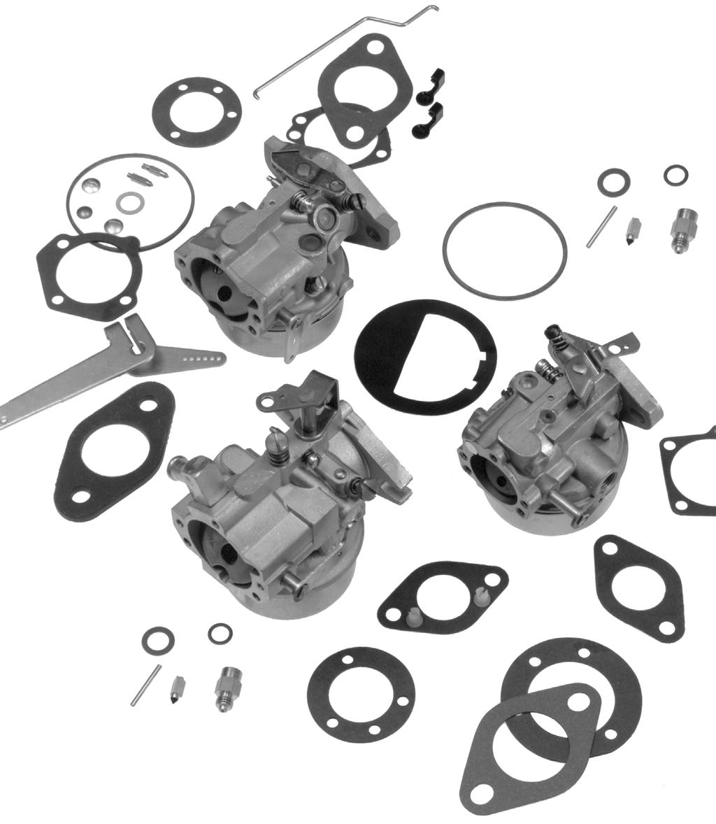
1 PLEASE NOTE: This is a PRELIMINARY copy of the Carburetor Reference Manual. Carburetor Service Kits The carburetors for most current production engines are serviced with convenient kits, which include the necessary gaskets, hardware, sealant, etc. The following table lists the service kits by engine model and carburetor manufacturer. For those carburetors where a float kit is not listed, order a rebuild kit which includes the float. Engine Carburetor Gasket Rebuild Float Choke Repair Kit Model Mfr. Repl. Kit Kit Kit Standard Self-Reliev. CS4, 6 Mikuni S S CS8.5 (250cc) Mikuni S S CS Mikuni S S CH6 Keihin S S S CH/CV11-16 Walbro S S S CH/CV11-16 Nikki S S S S TH16, 18 Nikki S S S S CH18-25 Keihin S S S CV17-25 Nikki S S S CH/CV22/23 (674cc) Keihin S S S S LV Nikki S S S Engine Carburetor Solenoid Fuel Bowl Accelerator Pump Kit(s) Model Mfr. Kit Repl. Kit Seal & Bush. Diaphragm CS4, 6 Mikuni CS8.5 (250cc) Mikuni CS Mikuni CH6 Keihin CH/CV11-16 Walbro S S CH/CV11-16 Nikki S TH16, 18 Nikki S CH18-25 Keihin S S S CV17-25 Nikki S S CH/CV22/23 (674cc) Keihin S S LV Nikki S S

2 CARBURETORS CARBURETOR REFERENCE MANUAL
3 This reference manual contains information on the various types of carburetors used on Kohler engines. Section 1 is a part number cross reference to assist you in selecting the proper replacement carburetor or carburetor kit. Section 2 contains recommended carburetor adjustment procedures for Kohler and Walbro carburetors, and preliminary needle settings for all carburetors and engine models. Section 3 is a service parts listing. The cross reference listing will be periodically updated to reflect part number supersessions. All information in this manual is subject to change. For additional service and repair information see the appropriate service manual for your model engine. Section 1 Carburetor Cross Reference How To Use This Cross Reference 1. Prior to the serial breaks listed, use an original Kohler adjustable jet carburetor when available from Distributor s stock. Where serial breaks are not listed, and the engine was built with an original Kohler adjustable jet carburetor, use an original Kohler adjustable jet carburetor. 2. If an original Kohler adjustable jet carburetor is no longer available, and the engine serial number is prior to the serial break, order the corresponding Walbro fixed or adjustable jet carburetor kit. If the engine serial number is at or after the serial break, determine the part number of the carburetor installed on the engine. *The part number is stamped on the carburetor mounting flange.) 3. Locate the carburetor part number (from step 2) in either the Walbro Fixed Jet Car column or Walbro Adj Jet Carb column. Use the corresponding carburetor kit. 4. If a Walbro fixed jet carburetor kit is no longer available from Kohler Co./Distributor stock, use the corresponding Walbro adjustable jet kit. NOTE: Carburetors listed in the Walbro Fixed Jet Carb column and Walbro Adj Jet Carb column are for reference only. Always order the corresponding carburetor kit. Carburetor kits include a carburetor assembly, gasket and/or linkage. 1.1
4 Original Walbro Walbro Walbro Walbro Engine Kohler Serial Fixed Jet Fixed Adj. Jet Adj. Jet Model Adj. Carb. Break Carb. Kit* Jet Carb. Carb. Kit* Carb. K91 G K K181/M8 C B K ,M K321,M (KA) (WA) *Includes carburetor, gasket, and/or linkage. 1.2
5 Original Walbro Walbro Walbro Walbro Engine Kohler Serial Fixed Jet Fixed Adj. Jet Adj. Jet Model Adj. Carb. Break Carb. Kit* Jet Carb. Carb. Kit* Carb. K341,M (KA) (WA) (KA) (WA) (KA) (WA) (KA) (WA) K KT17-19/M18-MV20 KT17/M KT17/M KT17/M M M18/M KT19/M KT19/M M MV16/MV MV20 Not Available *Includes carburetor, gasket, and/or linkage. 1.3
6 Section 2 Carburetor Adjustment Kohler engines are equipped with one of two basic types of carburetors Kohler or Walbro fixed main jet or adjustable main jet. This section covers the carburetor adjustment procedures for all Kohler engines. Kohler carburetor adjustments are covered on pages 2.1 & 2.2. Walbro carburetor adjustments are covered on pages 2.3 & 2.4. Preliminary settings for both type carburetor is on page 2.5. The carburetor is designed to deliver the correct fuel-toair mixture to the engine under all operating conditions. The main fuel and low idle fuel needles on adjustable jet carburetors are set at the factory and normally do not need further adjustment. On fixed jet carburetors, the low idle fuel needle is also set at the factory and normally does not need further adjustment. The main fuel jet is calibrated and installed at the factory and is not adjustable*. *NOTE: Engines operating at altitudes above approximately 1830 m (6000 ft.) may require a special high altitude main jet. Troubleshooting If engine troubles are experienced that appear to be fuel system related, check the following areas before adjusting the carburetor. Make sure the fuel tank is filled with clean, fresh gasoline. Make sure the fuel tank cap vent is no blocked and that it is operating properly. Make sure fuel is reaching the carburetor. This includes checking the fuel shut-off valve, fuel tank filter screen, in-line fuel filter, fuel lines, and fuel pump for restrictions or faulty components as necessary. Make sure the air cleaner base and carburetor is securely fastened to the engine using gaskets in good condition. Make sure the air cleaner element is clean and all air cleaner components are fastened securely. Make sure the ignition system, governor system, exhaust system, and throttle and choke controls are operating properly. If, after checking the items listed above, starting or engine operation problems exists, it may be necessary to adjust the carburetor. NOTE: Carburetor adjustments should be made only after the engine has warmed up. Kohler Carburetor Adjustment In general, turning the adjusting needles in (clockwise) decreases the supply of fuel to the carburetor. This gives a leaner fuel-to-air mixture. Turning the adjusting needles out (counterclockwise) increases the supply of fuel to the carburetor. This gives a richer fuel-to-air mixture. Setting the needles midway between the lean and rich positions will usually give the best results. Adjust the carburetor as follows: 1. With the engine stopped, turn the low idle fuel adjusting needle in (clockwise) until it bottoms lightly. NOTE: The tip of the low idle fuel and main fuel adjusting needles are tapered to critical dimensions. Damage to the needles and the seats in carburetor body will result if the needles are forced. 2. Preliminary Settings: Turn the adjusting needles out (counterclockwise) from lightly bottomed according to the table shown in Figure Start the engine and run at half throttle for five to ten minutes to warm up. The engine must be warm before making final settings steps 4, 5, 6, and 7). 2.1
7 4. Main Fuel Needle Setting: This adjustment is required only for adjustable main jet carburetors. If the carburetor is a fixed main jet type, refer to Walbro adjustment. Place the throttle into the fast position. If possible, place the engine under lead. Turn the main fuel adjusting needle out (counterclockwise) from the preliminary setting until the engine speed decreases (rich). Note the position of the needle. Adjust to Midpoint Rich Lean Now turn the adjusting needle in (clockwise). The engine speed may increase, then it will decrease as the needle is turned in (lean). Note the position of the needle. Set the adjusting needle midway between the rich and lean settings. See Figure Low Idle Speed Setting: Place the throttle control into the idle or slow position. Set the low idle speed to 1200 RPM* (+ or 75 RPM) by turning the low idle speed adjusting screw in or out. Check the speed using a tachometer. Figure 2-1. Optimum Low Idle Fuel Setting. Walbro Carburetor Adjustment In general, turning the adjusting needles in (clockwise) decreases the supply fuel to the carburetor. This gives a leaner fuel-to-air mixture. Turning the adjusting needles out (counterclockwise) increase the supply of fuel to the carburetor. Adjust the carburetor as follows, see Figure 2-2 for needle locations. *NOTE: The actual low idle speed depends on the application. Refer to the equipment manufacturer s instructions for specific low idle speed settings. The recommended low idle speed for the Basic Engines is 1200 RPM. To ensure best results when setting the low idle fuel needle, the low idle speed must not exceed 1500 RPM. 6. Low Idle Fuel Needle Setting: Place the throttle into the idle or slow position. Idle Speed Screw Low Idle Fuel Needle Main Fuel Needle Turn the low idle fuel adjusting needle out (counterclockwise) from the preliminary setting until the engine speed decreases (rich). Note the position of the needle. Now turn the adjusting needle in (clockwise). The engine speed may increase, then it will decrease as the needle is turned in (lean). Note the position of the needle. Set the adjusting needle midway between the rich and lean settings. See Figure Recheck the low idle speed using a tachometer. Readjust the speed as necessary. Figure 2-2. Adjusting Needle Locations. NOTE: The tip of the low idle fuel and main fuel adjusting needles are tapered to critical dimensions. Damage to the needles and the seats in carburetor body will result if the needles are forced. Refer to Figure 2-5 for preliminary settings. 1. With the engine stopped, turn the adjusting needle(s) in (clockwise) until it bottoms lightly. 2.2
8 2. Preliminary Settings: Turn the adjusting needle(s) out (counterclockwise) from lightly bottomed according to the table shown in Figure 2-5, or to the rich side of adjustment. 3. Start the engine and run at half throttle for five to ten minutes to warm up. The engine must be warm before making final settings. 4. Main Fuel Needle Setting: This adjustment is required only for adjustable main jet carburetors. If the carburetor is a fixed main jet type, disregard this setting. Place the throttle into the fast position. Turn the adjusting needle in (clockwise). The engine speed may increase, then it will decrease as the needle is turned in (lean). Note the position of the needle. Back the needle out approximately 1/8 to 1/4 turn. See Figure 2-3 for best main fuel performance. 6. Low Idle Fuel Needle Setting: Place the throttle into the idle or slow position. Turn the adjusting needle in (clockwise). The engine speed may increase, then it will decrease as the needle is turned in (lean). Note the position of the needle. Back the needle out approximately 1/8 to 1/4 turn. See Figure 2-4 for best low idle fuel performance. Lean Back Out Approx. 1/8 to 1/4 Turn Lean Back Out Approx. 1/8 to 1/4 Turn Figure 2-4. Optimum Low Idle Fuel Setting. Lean Lean Figure 2-3. Optimum Mail Fuel Setting. 5. Low Idle Speed Setting: Place the throttle control into the idle or slow position. Set the low idle speed to 1200 RPM* (+ or 75 RPM) by turning the low idle speed adjusting screw in or out. Check the speed using a tachometer. *NOTE: The actual low idle speed depends on the application. Refer to the equipment manufacturer s instructions for specific low idle speed settings. To ensure best results when setting the low idle fuel needle, the low idle speed must not exceed 1500 RPM. 2.3
9 Preliminary Settings K-Series Models Walbro Kohler Adjustable Jet Fixed Jet Walbro Adjustable Jet Low Idle High Idle Low Idle Low Idle Main Fuel K91 1-1/2 turns 2 turns NOT APPL 1-3/4 turns 3/4 turn K /2 turns 3 turns NOT APPL NOT APPL NOT APPL K161* 1-1/2 turns 3 turns NOT APPL 2-1/4 turns 1-1/8 turns K181* 1-1/4 turns 2 turns 2-1/2 turns 2-1/2 turns 3/4 turn K /2 turns 2 turns 1-1/4 turns 1-3/4 turns 1-1/8 turns K /2 turns 2 turns 1-1/2 turns 1-3/4 turns 1-1/8 turns K /2 turns 3-1/4 turns 1-1/2 turns 1-1/8 turns 1-1/4 turns K /2 turns 3-1/2 turns 1 turn 2-1/2 turns 1-1/4 turns KT17 1 turn 2-1/2 turns 1-1/4 turns 1-1/4 turns 1-1/4 turns KT19 1 turn 2-1/2 turns 1-1/4 turns 1-1/4 turns 1 turn K /4 turns 3 turns NOT APPL 2 B DETERMINED2 B DETERMINED *Includes New Look" Models Magnum Models Walbro Kohler Adjustable Jet Fixed Jet Walbro Adjustable Jet Low Idle High Idle Low Idle Low Idle Main Fuel M8 1-1/4 turns 2 turns 2-1/2 turns 2-1/2 turns 3/4 turn M10 2-1/2 turns 2 turns 1-1/4 turns 1-3/4 turns 1-1/8 turns M12 2-1/2 turns 2 turns 1-1/4 turns 1-3/4 turns 1-1/8 turns M14 2-1/2 turns 3-1/4 turns 1-1/2 turns 1-1/8 turns 1-1/4 turns M16 2-1/2 turns 3-1/2 turns 1 turn 2 turns 7/8 turn M18 1 turn 2-1/2 turns 1-1/4 turns 1-1/4 turns 1-1/4 turns M20 1 turn 2-1/2 turns 1-1/4 turns 1-1/4 turns 1 turn MV16/18 NOT APPL NOT APPL 1-1/4 turns 1-1/4 turns 1-1/4 turns MV20 NOT APPL NOT APPL 1-1/4 turns 1-1/4 turns 1 turn Command Models Walbro Kohler Adjustable Jet Fixed Jet Walbro Adjustable Jet Low Idle High Idle Low Idle Low Idle Main Fuel C5 NOT APPL NOT APPL 1 turn NOT APPL NOT APPL CV12.5 NOT APPL NOT APPL 1 turn NOT APPL NOT APPL Figure
10 Section 3 SERVICE PARTS LISTING This section contains indexed illustrations and complete part number breakdowns for the Kohler adjustable and Walbro fixed/adjustable carburetors. The Kohler carburetors are covered on pages /2 Walbro carburetors are covered on pages Walbro carburetors are covered on pages Here is a listing for quick reference of all fixed main jets and high altitude jet kits and jet size. Fixed Main Jets Kohler Part No. Jet Size High Altitude Jet Kits Kohler Part No. Jet Size
11 1/2" Kohler Adjustable Carburetor Carburetor Connector Needle, Hi Spring, Hi Spring, Idle Needle, Idle Spring, Idle Screw, Idle Gasket Part No. Hose Speed Adj Spd Needle Needle Adj. Screw Adj Bowl Float Kit G C B X " Kohler Adjustable Carburetor Carburetor Connector Needle, Hi Spring, Hi Spring, Idle Needle, Idle Spring, Idle Screw, Idle Gasket Float Part No. Hose Speed Adj Spd Needle Needle Adj. Screw Adj Bowl Kit *Included in Carburetor Repair Kit 3.2
12 1/2" Kohler Adjustable Carburetor Gasket, Pin, Spring, Bowl, Screw, Bowl Gasket, Bowl Shaft Repl Carburetor Bowl Baffle Float Float Fuel Retainer ret. Screw Repair Kit Kit Part No G C B /2" Kohler Adjustable Carburetor Gasket, Pin, Spring, Bowl, Screw, Bowl Gasket, Bowl Shaft Repl Swivel Carburetor Bowl Baffle Float Float Fuel Retainer ret. Screw Repair Kit Kit Clamp Kit Part No *Included in Carburetor Repair Kit 3.3
13 1" Kohler Adjustable Carburetor Carburetor Connector Needle, Hi Spring, Spring Needle Spring Screw Gasket, Float Part No. Hose Speed Adj Hi-Speed Idle Needle Idle Adj Idle Idle Adj Bowl Kit X X X X X X X *Included in Carburetor Repair Kit 3.4
14 1" Kohler Adjustable Carburetor Gasket, Pin Spring, Bowl, Screw, Gasket Repair Shaft Solenoid Carburetor Bowl Baffle Float Float Fuel Bowl Ret. Bowl Ret. Kit Repl. Kit Kit Part No *Included in Carburetor Repair Kit 3.5
15 1/2" Walbro Fixed/Adjustable Carburetor Carb Screw, Spring Screw Spring Spring Needle Thr. Part Thr.& Ch. Plate, Ball, Spring, Main Needle Throttle Throttle Idle Idle Shaft No. Plate Choke Choke Choke Needle Hi-Speed Adj. Adj. Needle Adj. W/Seal *Included in Carburetor Repair Kit 3.6
16 1/2" Walbro Fixed/Adjustable Carburetor Gasket, Screw, Hi-Alt Carb. Plate, Shaft, Jet, Gasket, Float Bowl Bowl Retl Bow Repair Jet Part Throttle Choke Main Bowl Kit Fuel Screw Retainer Kit Kit No *Included in Carburetor Repair Kit 3.7
17 1" Walbro Fixed/Adjustable Carburetor Carb Screw Thr. Needle, Speed, Needle Spring, Spring, Part Thr. & Plate, Ball, Spring, Fitting, Shaft Plate, Idle Idle High, Main Thr. No. Ch. Plate Choke Choke Choke Breather W/Seal Throttle Adj. Needle Speed Needle Adj *Included in Carburetor Repair Kit 3.8
18 1" Walbro Fixed/Adjustable Carburetor Screw, Gasket, Screw, Carb. Thr. Shaft, Jet, Gasket, Float Bowl, Bowl Ret. Bowl Repair Hi-Alt Solenoid Part Adj. Choke main Bowl Kit Fuel Screw Retainer Kit Jet Kit Kit No *Included in Carburetor Repair Kit 3.9
19 1" Walbro Fixed/Adjustable Carburetor cont. Carb Screw, Thr. Needle, Spring, Needle, Spring, Spring, Part Thr. & Plate, Ball, Spring, Fitting Shaft Plate, Idle Idle Hi- Main Thr. No. Ch. Plate Choke Choke Choke Breather W/Seal Throttle Adj. Needle Speed Needle Adj *Included in Carburetor Repair Kit 3.10
20 1" Walbro Fixed/Adjustable Carburetor cont. Gasket, Screw, Carb. Screw, Shaft, Jet, Gasket, Float Bowk Bowl Ret. Bowl Repair Hi-Alt Solenoid Part Thr. Adj. Choke Main Bowl Kit Fuel Screw Retainer Kit Jet Kit Kit No *Included in Carburetor Repair Kit 3.11
CARBURETION. Flo-Jet Carburetors. One Piece. One-Piece Flo-Jet. Main Jet Adjustment N eedle
 One Piece One-Piece Flo-Jet The small One-Piece Flo-Jet carburetor is illustrated in Fig. 122 and was used on early Model 170700. These are float feed carburetors with adjustable orifice main jet needle
HORSEPOWER TO MODEL NUMBER
 MODEL REFERENCE CHARTS HORSEPOWER TO MODEL NUMBER HP RATING MODEL NUMBERS HP RATING MODEL NUMBERS 4.9 K90, K91 5.0 K121, C5 6.0 K141, CH6 7.0 K160, K161, L160, L161 8.0 K12,K181,L181, M8 10.0 K241, M10
CARBURETION. Tank Mount, Horizontal Crankshaft. Vacu-Jet - All
 Page 1 of 1 Vacu-Jet - All Carburetor Adjustment Initial 1. Turn adjustment needle clockwise until it makes light contact with the seat. Do not force. 2. The initial setting of adjustment needle is made
Tillotson Tc3A Carburator
 Tillotson Tc3A Carburator 176 FUEL SYSTEMS - 5B-11 CENTER BOWL TYPE CARBURETOR Removal 1. Remove front cowl cover and wrap-around cowl. 2. Remove swivel link from lower carburetor. (Figure 2) 3. Loosen
Nikki Carburetor Vertical Models , ,
 Nikki Carburetor Vertical Models 280000, 310000, 330000 Disassemble Carburetor 1. Remove fuel bowl screws (A, Figure 56). Remove the fuel bowl (B) from the carburetor body. WARNING Before servicing the
Typical Install Instructions
 Typical Install Instructions Read & understand all steps of these instructions before beginning this installation. WEBER Conversion Kit, VW T-1/2, up to 1835cc 32 / 36 DFEV Weber Carburetor These instructions
CARBURETION. Carburetor Identification. Models , , , , , , , , , , ,
 Carburetor Identification Models 110400, 110600, 111400, 111600, 113400, 120400, 120600, 121400, 121600, 122600, 123400, 123600 Models 28S700, 311700 Service Carburetor Briggs & Stratton/Walbro LMS Models
5. FUEL SYSTEM 5-0 FUEL SYSTEM MXU 250R/300R
 5 FUEL SYSTEM 5 SERVICE INFORMATION------------------------------------------------ 5-2 TROUBLESHOOTING----------------------------------------------------- 5-3 FUEL TANK -----------------------------------------------------------------
Do not bend or twist the control cable. Damaged control cable will not operate smoothly and may stick or bind.
 XL200 4. FUEL SYSTEM SERVICE INFORMATION 4-1 TROUBLESHOOTING 4-2 CARBURETOR 4-3 PILOT SCREW ADJUSTMENT 4-14 ACCELERATOR PUMP ADJUSTMENT 4-15 AIR CLEANER HOUSING 4-15 FUEL TANK 4-16 SERVICE INFORMATION
5. FUEL SYSTEM FUEL SYSTEM 5-0
 5 FUEL SYSTEM 5-0 SERVICE INFORMATION GENERAL INSTRUCTIONS SERVICE INFORMATION...5-1 CARBURETOR INSTALLATION...5-9 TROUBLESHOOTING...5-1 PILOT SCREW ADJUSTMENT...5-10 CARBURETOR REMOVAL...5-2 AUTO BYSTARTER...5-3
~. a~' ~ ( I o~~~ 4-0. ~Sj~' AO~ i/~ CB1000C (ij)aon'da in-ib) ~ "" ~ ~!~~P. ~ J N m (6-12 kg-em,
aon'da in-ib) ~ ~ ~!~~P. ~ J N m (6-12 kg-em,") e V ~. a~' ~ I ~ J C t \"" 8.0- ( I o~~~ ~ "" ~ ~. ~!~~P. C8 0 & 0,-t. ~ CB1000C (ij)aon'da 0.6-1.2 N m (6-12 kg-em, 5-10 in-ib) 4-0 / 4.0-6.0 N m (40-60 kg-em, 35-52 in-i b) t$ "'07~ / c;:::/ j ~Sj~'
e V ~. a~' ~ I ~ J C t \"" 8.0- ( I o~~~ ~ "" ~ ~. ~!~~P. C8 0 & 0,-t. ~ CB1000C (ij)aon'da 0.6-1.2 N m (6-12 kg-em, 5-10 in-ib) 4-0 / 4.0-6.0 N m (40-60 kg-em, 35-52 in-i b) t$ "'07~ / c;:::/ j ~Sj~'
7. FUEL SYSTEM ('04 - '05)
") 7. FUEL SYSTEM ('04 - '05) SYSTEM COMPONENTS 7-2 CARBURETOR DISASSEMBLY 7-81 SERVICE INFORMATION 7-3 CARBURETOR ASSEMBLY 7-14 TROUBLESHOOTING 7-4 CARBURETOR INSTALLATION 7-21 AIR CLEANER HOUSING 7-5 PILOT
7. FUEL SYSTEM ('04 - '05) SYSTEM COMPONENTS 7-2 CARBURETOR DISASSEMBLY 7-81 SERVICE INFORMATION 7-3 CARBURETOR ASSEMBLY 7-14 TROUBLESHOOTING 7-4 CARBURETOR INSTALLATION 7-21 AIR CLEANER HOUSING 7-5 PILOT
FUEL SYSTEM. Table of Contents. Specifications. Section 3A Fuel Delivery System. Models 6/8/9.9/10/15 CARBURETOR SPECIFICATIONS
 FUEL SYSTEM Section 3A Fuel Delivery System Table of Contents Specifications............................. 3A-1 WMC Carburetor Specifications............. 3A-2 WMC Carburetor Specifications.............
Checking Solenoid Plunger Travel
 1985 Chevy Truck EL Camino V8-305 5.0L Page 1 Carburetor: Adjustments Carburetor Calibration E2M & E4M Series Mixture Control Solenoid Plunger Travel Checking Solenoid Plunger Travel OTE: Mixture control
Section 5 Fuel System and Governor
 Section Description The Command horizontal twins use three different types of fuel systems; carbureted, electronic fuel injection (EFI), or gaseous. Gaseous fuel systems can be either liquefied petroleum
Performer Series Carburetor Rebuild Kit Catalog #1477 Models
 Please read these instructions carefully before attempting to rebuild your carburetor. Make sure to refer to your carburetor Owner s Manual for further information if need be. If you have any questions
TECH INFORMATION EMPI D Performance 2-Barrel Carburetor
 TECH INFORMATION EMPI D Performance 2-Barrel Carburetor The New EMPI D 2-Barrel Performance Carburetor.Built specifically for the VW Aftermarket. With all the features that you have asked for More Progression
CARBURETOR SERVICE INFORMATION TROUBLESHOOTING THROTTLE VALVE DISASSEMBLY THROTTLE VALVE INSTALLATION...
 11 CARBURETOR SERVICE INFORMATION... 11-2 TROUBLESHOOTING... 11-2 THROTTLE VALVE DISASSEMBLY... 11-3 THROTTLE VALVE INSTALLATION... 11-4 CARBURETOR REMOVAL... 11-5 AUTO BYSTARTER... 11-6 FLOAT CHAMBER...
Russian Motorcycle Carburetors
 Ural (Урал) - Dnepr (Днепр) Russian Motorcycle Carburetors Part V-12: VM 28mm Mikuni (See Also Part V-12A: VM Mikuni Carb Manual and Part V-12B: Mikuni Overhaul) Ernie Franke eafranke@tampabay.rr.com 03
SECTION 4 - FUEL SYSTEMS AND CARBURETION
 SECTION - FUEL SYSTEMS AND CARBURETION FUEL SYSTEMS - - - - - - - - - - - - - - - - - - - - - - - - - - - - - - - - - - - - - - - - - - - - - - - - - - - - - - - - - - - - - -62 FUEL PUMP - - - - - - -
11. CARBURETOR 11-0 CARBURETOR ZX / SCOUT 50
 11 CARBURETOR SERVICE INFORMATION... 11-2 TROUBLESHOOTING... 11-2 THROTTLE VALVE DISASSEMBLY... 11-3 THROTTLE VALVE INSTALLATION... 11-4 CARBURETOR REMOVAL... 11-5 AUTO BYSTARTER... 11-6 FLOAT CHAMBER...
Днепр) Russian Motorcycle Carburetors Part 11: VM 28mm Mikuni
 Russian Motorcycle Carburetors Part 11: VM 28mm Mikuni") Ural (Урал( Урал) - Dnepr (Днепр( Днепр) Russian Motorcycle Carburetors Part 11: VM 28mm Mikuni (See Also Part 11A: VM Mikuni Carb Manual) Ernie Franke eafranke@tampabay.rr.com 04/2011 Mikuni VM-28 Round-Slide
Ural (Урал( Урал) - Dnepr (Днепр( Днепр) Russian Motorcycle Carburetors Part 11: VM 28mm Mikuni (See Also Part 11A: VM Mikuni Carb Manual) Ernie Franke eafranke@tampabay.rr.com 04/2011 Mikuni VM-28 Round-Slide
TROUBLESHOOTING FLOW CHARTS
 TROUBLESHOOTING FLOW CHARTS Bowl Style Carburetor Troubleshooting Hunts and Surges Will Run only on Prime Will run only if the choke is used Determine that the governor system is functioning properly
Illustrated Parts List to
 FORM MS-9491 6/94 REPLACES FORM MS-9491 8/93 FILE IN SECT. 2 OF SERVICE MANUAL 404700 to 404799 Illustrated Parts List Model Series 404700 to 404799 TYPE NUMBERS 1200 through 1207, 1211 through 1214, 1400,
ENGINE ADJUSTMENTS. Remote Controls
 ENGINE ADJUSTMENTS Remote Control Wire Travel The remote control wire should measure 2.25 (54 mm) when extended outside the casing (Figure 2). After installation, the travel of the remote control wire
Racing Performance Catalog & Reference Guide Model/Type:
 Version 4/08 Racing Performance Catalog & Reference Guide Model/Type: 124435 8105-01 Table of Contents SAFETY... 1 WORLD FORMULA General Specs...3 Special Tools...3 Torque Specs...3 Racing Specifics...3
12. CARBURETOR/FUEL PUMP
 12 CARBURETOR/FUEL PUMP SERVICE INFORMATION... 12-2 TROUBLESHOOTING... 12-2 THROTTLE VALVE DISASSEMBLY... 12-3 THROTTLE VALVE INSTALLATION... 12-4 CARBURETOR REMOVAL... 12-5 AUTO BYSTARTER... 12-6 FLOAT
INSIDE YOUR HOLLEY CARBURETOR FUEL INLET SYSTEM
 INSIDE YOUR HOLLEY CARBURETOR The carburetor is quite simply a fuel metering device that operates under the logical and straightforward laws of physics. It has evolved over the years from a very simple
Reproduction. Not for. Briggsracing.com. CORPORATION Briggs & Stratton Corporation MS /08
 Briggsracing.com MS-5702-4/08 BRIGGS&STRATTON CORPORATION Post office box 702 Milwaukee, WI 53201 USA 414 259 5333 2008 Briggs & Stratton Corporation Version 4/08 Racing Performance Catalog & Reference
Illustrated Parts List. Model Series 31A600. TYPE NUMBERS 0111 Through TABLE OF CONTENTS
 Illustrated Parts List Model Series 31A600 TYPE NUMBERS 0111 Through 4139. TABLE OF CONTENTS FORM MS3735 REV S 11/21/2012 REPLACES FORM MS3735 REV R 05/08/2012 FILE IN SECT. 2 OF SERVICE MANUAL 31A600
235/245400, , 28N
 Models 235/245400, 287000, 28N thru W, 310/312/313700 These carburetors have a fixed high speed main jet with adjustable idle, Fig 183. The different carburetors are identified as LMT 1 and up. The letters
4. FUEL SYSTEM CK 1 4-0
 4 4 4-0 SERVICE INFORMATION... 4-1 FLOAT LEVEL INSPECTION... 4-5 TROUBLESHOOTING... 4-2 CARBURETOR INSTALLATION... 4-6 THROTTLE VALVE DISASSEMBLY... 4-3 THROTTLE VALVE ASSEMBLY... 4-6 CARBURETOR REMOVAL...
CARTER DOWNDRAFT CARBURETOR Terraplane All Models. Technical Information
 CARTER DOWNDRAFT CARBURETOR 1934 Terraplane All Models Technical Information . Carter W-1 Downdraft Carburetors 1934 Terraplane Challenger, Model KS NOTE: Terraplane Models. Carburetor fitted with Anti-
13. FUEL SYSTEM/CARBURETOR/
 13 FUEL SYSTEM/CARBURETOR/FUEL PUMP FUEL SYSTEM --------------------------------------------------------- 13-1 SCHEMATIC DRAWING ---------------------------------------------- 13-2 OPERATION OF CARBURETOR
Illustrated Parts List
 FORM MS 56 08/11/2004 REPLACES FORM MS 56 11/14/2002 FILE IN SECT. 2 OF SERVICE MANUAL 312700 Illustrated Parts List Model Series 312700 TYPE NUMBERS 0101 through 01. TABLE OF CONTENTS Air Cleaner.........................
SECTION 4 - FUEL/LUBRICATION/COOLING
 For Arctic Cat Discount Parts Call 606-678-9623 or 606-561-4983 SECTION 4 - FUEL/LUBRICATION/COOLING 4 TABLE OF CONTENTS Carburetor Specifications... 4-2 Carburetor Schematic... 4-2 Carburetor... 4-3 Cleaning
Illustrated Parts List
 FORM MS 54 08/11/2004 REPLACES FORM MS 54 11/14/2002 FILE IN SECT. 2 OF SERVICE MANUAL 311700 Illustrated Parts List Model Series 311700 TYPE NUMBERS 0005 through 0209. TABLE OF CONTENTS Air Cleaner.........................
Sherco Carb Jetting Instructions
 Sherco Carb Jetting Instructions This manual provides instructions on how to remove and reinstall the stock carburetor, it also shows you how to change the pilot jet and the main jet. It is intended to
Illustrated Parts List to
 Illustrated Parts List Model Series 124800 to 124899 FORM MS-2436-9/94 REPLACES FORM MS-2436-10/93 FILE IN SECT. 2 OF SERVICE MANUAL 124800 to 124899 TYPE NUMBERS 0106, 0206 through 0284, 0406 through
Illustrated Parts List. Model Series 31A700. TYPE NUMBERS 0112 through TABLE OF CONTENTS
 Illustrated Parts List Model Series 31A700 TYPE NUMBERS 0112 through 2454. TABLE OF CONTENTS FORM MS5533 REV R 11/30/2012 REPLACES FORM MS5533 REV P 05/08/2012 FILE IN SECT. 2 OF SERVICE MANUAL 31A700
FUEL SYSTEM CIRCUIT D'ESSENCE KRAFTSTOFFSYSTEM
 CIRCUIT D'ESSENCE KRAFTSTOFFSYSTEM 41 FUEL SYSTEM SERVICE INFORMATION TROUBLESHOOTING FUEL TANK AIR CLEANER CARBURETOR REMOVAL VACUUM CHAMBER FLOAT CHAMBER 4-1 PILOT SCREW 4-2 CARBURETOR SEPARATION 4-3
HSR Carburetor. Total Kits. Installation Instructions. # Evo Big Twin # present Twin Cam
 HSR Carburetor Total Kits Installation Instructions HSR42 Kits: HSR45 Kits: #42-8 84-99 Evo Big Twin #42-19 99 - present Twin Cam #45-2 84-99 Evo Big Twin #45-3 84-99 Evo Big Twin #45-4 99 - present Twin
Illustrated Parts List Industrial/Commercial to
 FORM MS-9479 6/95 REPLACES FORM MS-9479 10/94 FILE IN SECT. 2 OF SERVICE MANUAL 402700 to 402799 Illustrated Parts List Industrial/Commercial Model Series 402700 to 402799 TYPE NUMBERS 1115 through 1117,
Illustrated Parts List Vanguard to Compliance
 Non-Compliance Illustrated Parts List Vanguard Model Series 104700 to 104799 FORM MS-9878 7/93 REPLACES FORM MS-9878 5/92 FILE IN SECT. 2 OF SERVICE MANUAL 104700 to 104799 Compliance TYPE NUMBERS 0101,
BRAWLER SERIES CARBURETORS
 BRAWLER SERIES CARBURETORS Installation Instructions Please Stop and Read these Instructions before proceeding. If you do not fully understand the installation and tuning instructions you should seek professional
Setting up and adjusting SU/Hitachi carbs on the Datsun Roadster by Keith Williams. Service screw
 Setting up and adjusting SU/Hitachi carbs on the Datsun Roadster by Keith Williams Service screw This is the service screw it s only use it to raise the engine speed while adjusting the carbs. In normal
Illustrated Parts List. Model Series 31C700 TYPE NUMBERS 0005 THROUGH TABLE OF CONTENTS
 Illustrated Parts List Model Series 31C700 TYPE NUMBERS 0005 THROUGH 3346. TABLE OF CONTENTS Air Cleaner... 5 Alternator... 7 Blower Housing... 5 Camshaft... 2 Carburetor... 4 Controls... 7 Crankshaft...
HSR Carburetor. Total Kits. Installation Instructions. # Evo Big Twin # present Twin Cam
 HSR Carburetor Total Kits Installation Instructions HSR42 Kits: HSR45 Kits: #42-8 84-99 Evo Big Twin #42-19 99 - present Twin Cam #45-2 84-99 Evo Big Twin #45-3 84-99 Evo Big Twin #45-4 99 - present Twin
ALTITUDE KIT FOR 79CC GASOLINE INVERTER - Westinghouse Part No
 ALTITUDE KIT HIGH ALTITUDE REPLACEMENT KIT Engine performance decreases as altitude increases. Proper operation can be ensured by installing an altitude kit when required. See the table below to determine
HUDSON MOTOR CAR COMPANY
 HUDSON MOTOR CAR COMPANY 1935-1942 Carburetor Tune-up Manual ( for Hudson and Terraplane Models) Index Carter W-1 Downdraft 1935-1942 1 Carter W-1 Vacumeter Type 1938 Hudson 4 Carter WA-1 Vacumeter Type
Illustrated Parts List 31G700
 FORM MS 64 11/18/2004 REPLACES FORM MS 64 10/13/2004 FILE IN SECT. 2 OF SERVICE MANUAL 31G700 Illustrated Parts List Model Series 31G700 TYPE NUMBERS 0026 through 0294. TABLE OF CONTENTS Air Cleaner.........................
Illustrated Parts List to
 TYPE NUMBERS 0101, 0102, 0106, 0108, 0109, 0115 through 0224, 0415, 0418, 0467, 0468, 0601 through 0683, 3101 through 3108, 3110 through 3163, 3167 through 3181. Illustrated Parts List Model Series 124700
Safety Precautions To insure safe operations please read the following statements and understand their meaning Also refer to your equipment owner's ma
 MAGNUM 18 & 20 HP HORIZONTAL CRANKSHAFT OWNER'S MANUAL 1 Safety Precautions To insure safe operations please read the following statements and understand their meaning Also refer to your equipment owner's
Illustrated Parts List. Model Series 31B700. TYPE NUMBERS 0005 through TABLE OF CONTENTS
 Illustrated Parts List Model Series TYPE NUMBERS 0005 through 0420. TABLE OF CONTENTS FORM MS--5534--04/15/2009 REPLACES FORM MS--5534--10/23/2008 FILE IN SECT. 2 OF SERVICE MANUAL Air Cleaner... 6 Alternator...
MAGNUM 18 & 20 HP HORIZONTAL CRANKSHAFT
 MAGNUM 18 & 20 HP HORIZONTAL CRANKSHAFT OWNER'S MANUAL Safety Precautions To ensure safe operations please read the following statements and understand their meaning. Also refer to your equipment owner's
Illustrated Parts List. 28R700 to 28R799
 Illustrated Parts List Model Series TYPE NUMBERS 0140, 0148, 0637, 0648, 1028, 1114, 1140, 1148, 1150. FORM MS 4990 2Q 9/2000 FORM MS 4990 10/99 FILE IN SECT. 2 OF SERVICE MANUAL TO FIND THE CORRECT NUMBER
Rochester Quadrajet Dodge
 Rochester Quadrajet Dodge ADJUSTMENTS Float Level EXTERNAL CHECK See Figure 1 Fig. 1: Float level external check for the Rochester Quadrajet 1. With the engine idling at normal operating temperature and
Illustrated Parts List. Model Series. TYPE NUMBERS 0026 through TABLE OF CONTENTS
 Illustrated Parts List Model Series TYPE NUMBERS 0026 through TABLE OF CONTENTS Air Cleaner... 5 Alternator... 7 Blower Housing... 5 Camshaft... 2 Carburetor... 4 Controls... 7 Crankshaft... 2 Cylinder...
Illustrated Parts List. Model Series 31X700 TYPE NUMBERS TABLE OF CONTENTS
 FORM MS--3506--01/19/2006 REPLACES FORM MS--3506--08/01/2005 FILE IN SECT. 2 OF SERVICE MANUAL 31X700 Illustrated Parts List Model Series 31X700 TYPE NUMBERS 0777. TABLE OF CONTENTS Air Cleaner... 5 Alternator...
INSTRUCTION SHEET ROCHESTER CARBURETOR MODELS 4MC 4MV
 INSTRUCTION SHEET ROCHESTER CARBURETOR MODELS 4MC 4MV GENERAL EXPLODED VIEW THE GENERAL DESIGN AND PARTS SHOWN WILL VARY TO INDIVIDUAL UNITS COVERED ON THIS INSTRUCTION SHEET DISASSEMBLY Use exploded view
Illustrated Parts List 28N700
 FORM MS 0148 09/14/2004 REPLACES FORM MS 0148 4C 12/1/2003 FILE IN SECT. 2 OF SERVICE MANUAL Illustrated Parts List Model Series TYPE NUMBERS 0026 through 1205. TABLE OF CONTENTS Air Cleaner.........................
Illustrated Parts List. Model Series 31Q700. TYPE NUMBERS 0036 Through TABLE OF CONTENTS
 Illustrated Parts List Model Series 31Q700 TYPE NUMBERS 0036 Through 3136. TABLE OF CONTENTS FORM MS5767 REV P 05/17/2012 REPLACES FORM MS5767 REV M 01/16/2012 FILE IN SECT. 2 OF SERVICE MANUAL 31Q700
Holley High Performance Intake System* For Port 13B Engines (Includes B 6-Port engines converted to 4-Port)
") Holley High Performance Intake System* For 1974-1978 4-Port 13B Engines (Includes 1984-85 13B 6-Port engines converted to 4-Port) Installation Instructions I-18038 Note: These instructions assume: The
Holley High Performance Intake System* For 1974-1978 4-Port 13B Engines (Includes 1984-85 13B 6-Port engines converted to 4-Port) Installation Instructions I-18038 Note: These instructions assume: The
Page 1 of HP B&S Vanguard Engine
 1405 Page 1 of 41 14 HP B&S Vanguard Engine 1405 Page 2 of 41 14 HP B&S Vanguard Engine Ref # Part Number Qty S/P/F Description BS-28Q777-0647-E1 1 14 HP B&S Vanguard Engine 1 BS-496412 1 Cylinder Assembly
12. CARBURETOR 12-0 CARBURETOR VITALITY 50
 12 12 CARBURETOR SERVICE INFORMATION (2-STROKE)... 12-2 SERVICE INFORMATION (4-STROKE)... 12-3 THROTTLE VALVE (2-STROKE)... 12-5 CARBURETOR (2-STROKE)... 12-7 AIR SCREW ADJUSTMENT (2-STROKE)... 12-13 REED
Illustrated Parts List. Model Series 21A900. TYPE NUMBERS 0101 through TABLE OF CONTENTS
 Illustrated Parts List Model Series TYPE NUMBERS 0101 through 0199. TABLE OF CONTENTS FORM MS--5069--03/17/2009 REPLACES FORM MS--5069--06/17/2008 FILE IN SECT. 2 OF SERVICE MANUAL Air Cleaner... 7 Alternator...
5. FUEL SYSTEM 5-0 FUEL SYSTEM UXV 500
 5 FUEL SYSTEM 5 SERVICE INFORMATION------------------------------------------------ 5-02 TROUBLESHOOTING----------------------------------------------------- 5-03 FUEL TANK -----------------------------------------------------------------
AN EXPLANATION OF CIRCUITS CARTER YH HORIZONTAL CLIMATIC CONTROL CARBURETER
 AN EXPLANATION OF CIRCUITS CARTER YH HORIZONTAL CLIMATIC CONTROL CARBURETER The Carter Model YH carbureter may be compared with a Carter YF downdraft carbureter with the circuits rearranged to operate
Illustrated Parts List 283H00
 FORM MS 5449 09/07/2006 REPLACES FORM MS 5449 09/12/2005 FILE IN SECT. 2 OF SERVICE MANUAL 283H00 Illustrated Parts List Model Series 283H00 TYPE NUMBERS 0105, 0197, 0399, 0400 TABLE OF CONTENTS Air Cleaner.........................
Illustrated Parts List. Model Series. TYPE NUMBERS 0035 through TABLE OF CONTENTS
 Illustrated Parts List Model Series TYPE NUMBERS 0035 through 0563. TABLE OF CONTENTS FORM MS--6359--08/04/2009 REPLACES FORM MS--6359--10/07/2008 FILE IN SECT. 2 OF SERVICE MANUAL Air Cleaner... 5 Alternator...
Illustrated Parts List. Model Series. TYPE NUMBERS 0026 through TABLE OF CONTENTS
 Illustrated Parts List Model Series 331800 TYPE NUMBERS 0026 through 4449. TABLE OF CONTENTS FORM MS3911 REV S 05/19/2012 REPLACES FORM MS3911 REV R 05/18/2012 FILE IN SECT. 2 OF SERVICE MANUAL 331800
EDELBROCK PERFORMER SERIES EMISSIONS LEGAL CARBURETOR 600cfm, Electric Choke, EGR, Square-Bore Carburetor. Part #1400 INSTALLATION INSTRUCTIONS
 EDELBROCK PERFORMER SERIES EMISSIONS LEGAL CARBURETOR 600cfm, Electric Choke, EGR, Square-Bore Carburetor INSTALLATION INSTRUCTIONS PLEASE study these instructions carefully before beginning this installation.
Mfg. No: B1
 Parts Manual Mfg. No: 295777-0002-B1 Copyright Briggs and Stratton. All Rights reserved 01-Apr-2018 Model Components Table Of Contents Page Air Cleaner...........................................................................................
Illustrated Parts List to
 FORM MS-5838-9/94 REPLACES FORM MS-5838-10/93 FILE IN SECT. 2 OF SERVICE MANUAL 122700 to 122799 Illustrated Parts List Model Series 122700 to 122799 TYPE NUMBERS 0101 through 0108, 0115 through 0213,
6. FUEL SYSTEM 6-1 FUEL TANK COMPONENT LOCATION 6-2 INTAKE PIPE SERVICE INFORMATION 6-3 CARBURETOR TROUBLESHOOTlNG 6-4
 6... COMPONENT LOCATION 6-2 SERVICE INFORMATION 6-3 TROUBLESHOOTlNG 6-4 AIR CLEANER HOUSING 6-5 FUEL TANK...... 6-5 INTAKE PIPE...... 6-6 CARBURETOR.............. 6-6 AIR SCREW ADJUSTMENT 6-15 6-1 COMPONENT
Illustrated Parts List. Model Series 31N800 TYPE NUMBERS TABLE OF CONTENTS
 Illustrated Parts List Model Series 31N800 TYPE NUMBERS 0440. TABLE OF CONTENTS FORM MS--3593--04/20/2009 REPLACES FORM MS--3593--09/25/2008 FILE IN SECT. 2 OF SERVICE MANUAL 31N800 Air Cleaner... 5 Alternator...
CARBURETOR P/N , C, S, & CT INSTALLATION, TUNING, AND ADJUSTMENT MANUAL 199R7950-7
 CARBURETOR P/N 0-7448, 0-4412C, 0-4412S, & 0-4412CT INSTALLATION, TUNING, AND ADJUSTMENT MANUAL 199R7950-7 NOTE: These instructions must be read and fully understood before beginning installation. If this
SERVICE CRANKSHAFTS CRANKSHAFT REFERENCE MANUAL
 SERVICE CRANKSHAFTS CRANKSHAFT REFERENCE MANUAL Section 1 General Information Table of Contents Table of Contents... 1.2 Crankshaft/Engine Identification... 1.3 Crankshaft PTO Measurement... 1.4 Woodruff
4. FUEL SYSTEM 4-0 FUEL SYSTEM NEXXON 50
 4 FUEL SYSTEM SERVICE INFORMATION ------------------------------------------------ 4-2 TROUBLESHOOTING----------------------------------------------------- 4-3 AIR CLEANER REMOVAL -----------------------------------------------
SECTION 4.05 FUEL SYSTEM MAINTENANCE F18/H24 AND L36/P48 ENGINES
 SECTION 4.05 SYSTEM MAINTENANCE F18/H24 AND L36/P48 ENGINES PHYSICAL REQUIREMENTS supply, pressure, and regulator type will vary with each application. Refer to S6656-23 for applicable regulator information.
Illustrated Parts List. Model Series 31F700. TYPE NUMBERS 0110 through TABLE OF CONTENTS
 Illustrated Parts List Model Series 31F700 TYPE NUMBERS 0110 through 0403. TABLE OF CONTENTS FORM MS--5035--04/27/2009 REPLACES FORM MS--5035--09/29/2008 FILE IN SECT. 2 OF SERVICE MANUAL 31F700 Air Cleaner...
Illustrated Parts List
 FORM MS 2247 11/29/2004 REPLACES FORM MS 2247 10/05/2004 FILE IN SECT. 2 OF SERVICE MANUAL 286700 Illustrated Parts List Model Series 286700 TYPE NUMBERS 0102 through 4529. TABLE OF CONTENTS Air Cleaner.........................
FUEL SYSTEM/CARBURETOR/FUEL PUMP
 13 FUEL SYSTEM/CARBURETOR/FUEL PUMP FUEL SYSTEM-------------------------------------------------------------------------------------13-1 SCHEMATIC DRAWING-------------------------------------------------------------------------13-2
3400 Gas Saw Page 1 of 25 Bow Guide & Chain Informatio
 3400 Gas Saw Page 1 of 25 Bow Guide & Chain Informatio 44235 13".050/ 3/8 pitch, P760-80 Bow Guide 51293 13".050/ 3/8 pitch, P760-80 Chain 44236 14".050/ 3/8 pitch, P760-87 Bow Guide 51294 14".050/ 3/8
WEBER CARBURETOR TROUBLESHOOTING GUIDE
 This guide is to help pinpoint problems by diagnosing engine symptoms associated with specific vehicle operating conditions. The chart will guide you step by step to help correct these problems. For successful
Illustrated Parts List
 FORM MS 2247 08/24/2007 REPLACES FORM MS 2247 06/02/2007 FILE IN SECT. 2 OF SERVICE MANUAL 286700 Illustrated Parts List Model Series 286700 TYPE NUMBERS 0102 through 4529. TABLE OF CONTENTS Air Cleaner.........................
Illustrated Parts List. Model Series 21B700 TYPE NUMBERS 0453, TABLE OF CONTENTS
 Illustrated Parts List Model Series 21B700 TYPE NUMBERS 0453, 0505. TABLE OF CONTENTS FORM MS--3675--10/20/2009 REPLACES FORM MS--3675--07/08/2009 FILE IN SECT. 2 OF SERVICE MANUAL 21B700 Air Cleaner...
Illustrated Parts List. Model Series. TYPE NUMBERS 0113 through TABLE OF CONTENTS
 Illustrated Parts List Model Series 219800 TYPE NUMBERS 0113 through 4389. TABLE OF CONTENTS FORM MS5709 REV P 11/08/2012 REPLACES FORM MS5709 REV N 04/24/2012 FILE IN SECT. 2 OF SERVICE MANUAL 219800
SERVICE. Accessories IPL, SV , Kohler 17 hp. Spare parts Ersatzteile Pièces détachées Reserve onderdelen Repuestos Reservdelar
 SERVICE Accessories IPL, SV0-000, 00-0 Kohler 7 hp Spare parts Ersatzteile Pièces détachées Reserve onderdelen Repuestos Reservdelar KOHLER ENGINE - MODEL NO. SV0, TYPE NO.000 7 0 7 0 0 7 0 7 7 KOHLER
S&S Cycle, Inc County Highway G Box 215 Viola, Wisconsin Phone: Fax:
 Instruction Sheet 51-1010 Revised 5-1-02 Copyright, 2002 by S&S Cycle, Inc. All rights reserved. Printed in the U.S.A. S&S Cycle, Inc. 14025 County Highway G Box 215 Viola, Wisconsin 54664 Phone: 608-627-1497
ILLUSTRATED PARTS BOOK. 196cc Rear Tine Tiller MODEL#: P-RTT-196MD-[E] MODEL#: P-RTT-196MD
![ILLUSTRATED PARTS BOOK. 196cc Rear Tine Tiller MODEL#: P-RTT-196MD-[E] MODEL#: P-RTT-196MD](/thumbs/73/69164090.jpg "ILLUSTRATED PARTS BOOK. 196cc Rear Tine Tiller MODEL#: P-RTT-196MD-[E] MODEL#: P-RTT-196MD") ILLUSTRATED PARTS BOOK 196cc Rear Tine Tiller MODEL#: P-RTT-196MD-[E] MODEL#: P-RTT-196MD 1 Table of Contents Upper Handle Assembly... 3 Base Assembly... 4 Parts List... 5-6 Tines &Tine Shield... 7-8 Transmission...
ILLUSTRATED PARTS BOOK 196cc Rear Tine Tiller MODEL#: P-RTT-196MD-[E] MODEL#: P-RTT-196MD 1 Table of Contents Upper Handle Assembly... 3 Base Assembly... 4 Parts List... 5-6 Tines &Tine Shield... 7-8 Transmission...
GENERAL DESCRIPTION ROCHESTER 4GC 4-JET CARBURETOR 6B PONTIAC SHOP MANUAL
 6B-56 1955 PONTIAC SHOP MANUAL GENERAL DESCRIPTION ROCHESTER 4GC 4-JET CARBURETOR The Rochester 4GC Carburetor for the 1955 Pontiac V -8 is essentially two 2 -J et carburetors in a single casting. The
Illustrated Parts List
 FORM MS 4183 10/31/2006 REPLACES FORM MS 9748 7/1997 FILE IN SECT. 2 OF SERVICE MANUAL 290700 Illustrated Parts List Model Series 290700 TYPE NUMBERS 0100, 0102, 0106, 0107, 0108, 0333, 0402, 0410. TO
CARBURETOR REBUILD KIT (Vacuum Secondary) Models Demon Carburetors & Holley Model 4160 LIT704
 Models Demon Carburetors & Holley Model 4160 LIT704") CARBURETOR REBUILD KIT 190000 (Vacuum Secondary) Models Demon Carburetors & Holley Model 4160 LIT704 INSTRUCTIONS: Before getting to the actual rebuild, it should be noted that the carbs shown here are
CARBURETOR REBUILD KIT 190000 (Vacuum Secondary) Models Demon Carburetors & Holley Model 4160 LIT704 INSTRUCTIONS: Before getting to the actual rebuild, it should be noted that the carbs shown here are
Kohler 19 hp. Spare parts Ersatzteile Pièces détachées Reserve onderdelen Repuestos Reservdelar I S E R V I C E
 S E R V I C E I0000 IPL, Kohler Courage hp, 00-0, 0-0 SV0-000 Kohler hp Spare parts Ersatzteile Pièces détachées Reserve onderdelen Repuestos Reservdelar 0-0 KOHLER ENGINE - MODEL NO. SV0, TYPE NO.000
TILLOTSON LTD., CLASH INDUSTRIAL ESTATE, TRALEE, CO. KERRY, IRELAND PHONE: FAX:
 TILLOTSON LTD., CLASH INDUSTRIAL ESTATE, TRALEE, CO. KERRY, IRELAND PHONE: +353 66 7121911 FAX: +353 66 7124503 e-mail: sales@tillotson.ie SERIES PARTS LIST Last update: JULY 2000 Illustration of basic
365-SUB Engine : Engine Assembly 365-SUB [1/1] Page 1 of 5
![365-SUB Engine : Engine Assembly 365-SUB [1/1] Page 1 of 5](/thumbs/91/105185559.jpg "365-SUB Engine : Engine Assembly 365-SUB [1/1] Page 1 of 5") Page 1 of 5 1 951-11012 Bolt 2 951-11054 Valve Cover 2 951-11054 1 Valve Cover 3 731-07059 Breather Hose 4 726-04101 Hose Clamp 6 N/A 1 Intake Valve Spring Seat 7 751-11124 Pivot Locking Nut 7 751-11124
Page 1 of 5 1 951-11012 Bolt 2 951-11054 Valve Cover 2 951-11054 1 Valve Cover 3 731-07059 Breather Hose 4 726-04101 Hose Clamp 6 N/A 1 Intake Valve Spring Seat 7 751-11124 Pivot Locking Nut 7 751-11124
Illustrated Parts List
 FORM MS 2791 10/05/2004 REPLACES FORM MS 2791 4C 6/2002 FILE IN SECT. 2 OF SERVICE MANUAL 289700 Illustrated Parts List Model Series 289700 TYPE NUMBERS 0102 through 4529. TABLE OF CONTENTS Air Cleaner.........................
Mfg. No: E1
 Parts Manual Mfg. No: 120312-0143-E1 Copyright Briggs and Stratton. All Rights reserved 05-Jan-2018 Model Components Table Of Contents Page Air Cleaner, Exhaust System...........................................................................
Illustrated Parts List to
 FORM MS-2442-9/93 REPLACES FORM MS-2442-11/92 FILE IN SECT. 2 OF SERVICE MANUAL Illustrated Parts List Industrial/Commercial Model Series TYPE NUMBERS 0101 through 0104, 0116 through 0120, 0122 through