Lecture 7. Coming week s lab: Integrative lab (your choice!)
|
|
|
- Abel Wheeler
- 6 years ago
- Views:
Transcription
1 Lecture 7 Coming week s lab: Integrative lab (your choice!) Today: Systems review exercise due end of class Your feedback Review: sequencing and asynchronous circuit analysis Hydraulic hybrid vehicles Valve modeling and sizing 1
2 How Hybrid Vehicles Save Energy? With a secondary power source/storage, it is possible to: Manage engine operation Store/reuse braking energy Turn off engine Downsize engine for continuous power Example vehicle on EPA-UDDS cycle: Baseline (10% engine efficiency): 24 mpg Engine management (38% efficiency): 95 mpg Above with regeneration: 140 mpg Engine 38% Energy storage Drive-train 10-15% Required for maximum performance wheel Normal driving operating range 2
 Electric motors & inverters (cost, power density) Affect")
3 Why Hydraulic Hybrids? Why not stick with electric hybrids? Electric batteries / ultracaps (cost, reliability, recycling, power density) Electric motors & inverters (cost, power density) Affect overall cost, weight, and power Metrics Fuel economy Cost Performance Toyota Prius 3
4 Hybrid Hydraulic versus Hybrid Electric Vehicle Hydraulic pump/motor have significantly higher power density than electric motor/generator (16:1 by weight, 8:1 by volume) Hydraulic drives have much lower torque density than electric drives Accumulators are 10x more power dense than batteries limits acc/braking and hence regenerative Efficient power electronics are expensive braking Batteries have 2 order magnitude higher energy density than accumulators Current hydraulic systems tend to be noisy and leaky Overall tradeoff: Hydraulic hybrids can be significantly lighter and cheaper than electric hybrids if energy density limitation can be solved. Engine Accumulator Accumulator Hydraulic pump/motor Engine Battery & ultracapacitor Electric motor/ generator Parallel Hybrid Hydraulic Parallel Hybrid Electric 4


5 Hydraulic Hybrids Versus Electric Hybrids Fluid Power Controls Laboratory (Copyright Perry Li, ) Performance Electric Fluid Power acceleration regenerative braking Component efficiency + - Regenerative efficiency Weight Cost Realize opportunities for Both performance & efficiency Cost and reliability Overcome threats in Inefficient components Low density energy storage Noise, vibration, harshness Reliability Environmental impact Energy storage NVH

6 Parallel Architecture Example: HLA system for F150 & garbage trucks Regenerates braking energy Utilizes efficient mechanical transmission Does not allow full engine management Achievable engine op. points 6
7 Series Architecture Example: Eaton/UPS (truck), Ford/EPA (Escape), Artemis (BMW-5), Regenerates braking energy Allows for full engine management Independent wheel torque control possible All power must be transmitted through fluid power components 38% 38% Required for maximum performance 10-15% 10-15% Normal driving Normal operating driving range operating range 7

8 Power-Split: Hydromechanical Transmission (HMT) Power split between mechanical and hydraulic paths Hybridized HMT i.e. w/ regeneration Efficient Mechanical Transmission Regenerative Braking Full engine management 8
9 Hypothesized hydraulic & overall efficiencies 0.7 Urban 0.45 Highway Overall efficiency series parallel hmt Overall efficiency series parallel hmt Mean hydraulic efficiency Mean hydraulic efficiency Series / HMT at peak engine efficiency (38.5%) Parallel at lower engine efficiency (33%) 9
10 191 Sequencing Circuits Sequence valve cracking pressure settings to enable proper sequencing Too high never cracks Too low simultaneous motion instead of sequence P1 F Crack at P_R 10
11 Asynchronous Circuit Analysis
12 Component Modeling - Pressure Reducing Valve 193 How do we write equations for this valve? Spool Force balance / Newton s law Spring Preload / Compression Orifice 12
13 194 Function: Regulate pressure at B Modeling Operation: If P_B is too large (small), spool moves up (down) to reduce (increase) orifice size P B A B ( F spring (x) F seat ) P D A D = M x A D F spr i n g A(x) B Preload x Possible Spring and area functions x 13
14 195 Directional Control Valves (DCVs) Controls direction of flow Fluidic symbol signifies function Manually or electrically (solenoid or equivalent elements) Can also meter flow proportional valve servo valve 14
15 196 15

16 197 Way-Position-Port, centering etc. # Position = number of possible positions for the valve shifting mechanism 2way infinite-pos 2port 1 = no shifting, 2={left, right}, 3={left, right, center}, infinite # Way = number of flow paths (including reverse flow) check valve = 1 way 1-way, 2-way, 3-way, 4-way most common. # Port = number of plumbing connections. Center = connection while neutral closed, open, tandem... 3way, 3position 3port 4way, 3position 4port 4way, infinite-pos 4port 16

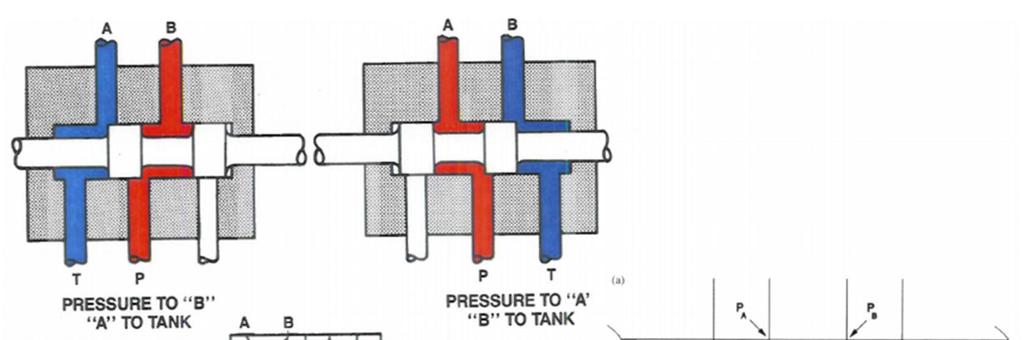
17 Four Way Directional Control Valve

18 199 Influences rest of circuit Energy / pressure when this part of circuit not used 4 way valve center Open center unload pump, energy saving for fixed displacement pump Can you use 2 cylinders? Closed center high pressure / relief responsive Tandem center (lab) allows 2 circuits in series 18

 for safety")
19 200 Single stage proportional valves Solenoids Spool is stroked directly by solenoid actuator LVDT spool position feedback Spring (sometimes) for safety 19
 solenoids / torque motors needed. Low end market.. Research: Using unstable flow force to improve spool agility K. Krishnaswamy and P. Y.")
20 Single Stage Proportional Valves 201 Advantages: Simple design Reliable Cost effective Disadvantages: Poor dynamic performance (bandwidth) At high flow rates and bandwidths, large stroking force is needed Large (and expensive) solenoids / torque motors needed. Low end market.. Research: Using unstable flow force to improve spool agility K. Krishnaswamy and P. Y. Li, On using unstable hydraulic valves for control ASME Journal of Dynamic Systems, Measurement and Control. Vol 124, No. 1, pp , March, Q.-H. Yuan and P. Y. Li, Using Steady Flow Force for Unstable Valve Design: Modeling & Experiments ASME Journal of Dynamic Systems, Measurement and Control. Vol 127, No. 3. pp , Q.-H. Yuan and P. Y. Li, Robust Optimal Design of Unstable Valves IEEE Transactions on Control Systems Technology. Vol. 15, No. 6, pp , November,

21 Multi-stage valves 202 Use hydraulic force to drive the spool.. 21

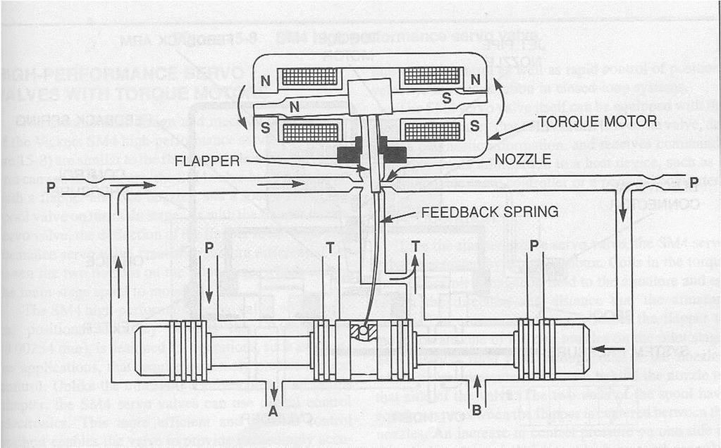
22 Electrohydraulic servo-valve Multi-stage valve Typically uses a flapper-nozzle pilot stage Built-in feedback via feedback wire Very high dynamic performance Bandwidth = Hz 203 Pilot stage Main stage For a fun place to learn how a servo-valve works: R. Dolid Electrohydraulic Valve Coloring Book pdf 22
23 Servo-Valve

 2.")

24 Feedback spring: 1. Regulates the position of the mainstage by negative feedback on the flapper Servo-Valve 205 Nozzle-flapper pilot valve: 1. Electromagnetic torque motor moves flapper to left (or right) 2. Nozzle and restriction at source form two resistances in series 3. Flapper differentially opens and closes nozzle 4. Pressure increases on side with closed nozzle; decreases on side with open nozzle; creating pressure differential Main stage: 1. Four-way spool valve actuated by differential pressure generated by pilot stage 24
25 206 Two spool servo valve Main spool consists of two spools one for meter-in, one for meter-out Reduces tolerance requirement Pilot stage is a pressure servo valve Cost effective Bandwidth around 30 Hz See below for a model of such a valve R. T. Anderson and P. Y. Li, Mathematical Modeling of a Two-spool Flow Control Servovalve Using a Pressure Control Pilot ASME Journal of Dynamic Systems, Measurement and Control Vol 124 No. 3, Sept (Sauer-Danfoss) 25
26 207 Modeling of directional control valve Spool is driven by solenoid (in a single stage valve) or by pilot stage(s) valves xv > 0 (spool moves downward) Assume matched (i.e. supply and return orifices are the same) Critically lapped symmetric, +/- spool displacement give same orifice area Flow conserving load Qin = Qout e.g. double ended cylinder or hydraulic motor 26
27 D.C. Valve modeling 208 Flow paths: (neglect leakages) xv > 0: Orifices 1 and 3 xv < 0: Orifices 2 and 4 Area of each orifice A1(xv), A2(xv), A3(xv), A4(xv) For xv > 0, [Cd = discharged coeff approx 0.6 (see notes on orifice modeling) Q Q 2 A1( xv ) ( Ps 1) 1 = Cd P 2 A3 ( xv) ( P2 0) 3 = Cd P Q 1 = Q 3 = Q L 27
28 D.C. Valve Modeling 209 Now the pressure across the load is: P L = P 1 P 2 Area gradient, w, relates orifice area to spool displacement. For circular orifices: w = 2 R Area gradient = w w = da dx A1(xv) = A3(xv) = w * xv A2(xv) = A1(-xv) = -w*xv v ( x v ) Annular orifice land Top view Solve for Q L when A1(xv) = A3(xv) =w xv (matched) to get: Q L 1 ( xv, PL ) = Cd wxv ( Ps PL ) circular Area versus xv Annular 28
 = Cd wxv ( Ps sgn( xv ) PL ) Flow increases linearly with xv Flow decreases")
29 DC Valve Modeling 210 Similar analysis for xv < 0: Q L 1 ( xv, PL ) = Cd wxv ( Ps PL ) Normally P L < 0 when xv < 0. Putting formulae for +/- xv together: Load overrun Positive power Q L 1 ( xv, PL ) = Cd wxv ( Ps sgn( xv ) PL ) Flow increases linearly with xv Flow decreases with pressure load Positive power Load overrun 29
 Overlapped (closed centered) valves deadband => un-responsive Underlapped (open")
30 211 Effect of lapping / centering For critically lapped (or sometimes called critically centered) valve Orifice is shut when xv = 0. At least one orifice will open when xv!=0 Critically lapped valves are desirable but expensive to make flow is linear with displacement (constant gain) Overlapped (closed centered) valves deadband => un-responsive Underlapped (open centered) valves valve always open => power loss nonlinear gain => more difficult to control 30

31 Valve Sizing 212 Valves are rated (i.e. their flow rate Q R given) at 1000 Psi pressure drop across the valve. i.e. Flow = Q R is flow when the valve is fully open and with 1000 PSI pressure drop There are two flow orifices (1 and 3) in flow path. It is assumed that pressure drop is 500psi across each orifice. Since one does not always use the valve when there is 1000 Psi pressure drop, one must translate the required flow to the equivalent flow at 1000 Psi. Basic equation: 2 Q L( xv, PL ) = Cd wxmax ( Ps P1 ) 2 Q L( xv, PL ) = Cd wxmax ( P2 P0 ) 31
32 Valve Sizing 213 At rated condition, Ps - P1= 500Psi, P2 - P0 = 500psi 2 Q L( xv, PL ) = Cd wx max ( Ps P1 ) 2 Q L( xv, PL ) = Cd wx max ( P2 P0 ) Suppose actual operating (Ps-P1) is 700 instead, with required flow Qd, then we would like: So the rated flow should be at least: Q R1 = Q d1 Q d = 500 P P s C wx Similarly, calculate for the return orifice: pick the larger rated flow 1 d max Q R= Q d Q R = C d wx max Pick this when picking valve 32
33 Valve sizing example 214 Given Ps = 3000 psi; P 0 = 0 psi Load is a 2:1 cylinder, capside A cap = m^2. Required extension speed = 1 m/s Load F = 500 lb-f. Step 1: Find Qd1 = speed * Acap.; Qd2 = Qd1/2 Step 2: find P1 and P2 during operating conditions 8F Ps P1 = 2Ps 2F P2 = 9A 9 cap 9A Step 3: find rated flow based on each orifice 9 cap P1 P2 A cap ( 1 2 P P / 2) = F ( P s P1 ) = 2 ( P2 P0 ) F Why? Q R1 = Q d1 500 P P s 1 Q R2 = Q d P P 2 0 Q Q R Q R1, R2 33
34 215 Other component sizing Actuator: stroke: how far does it have to travel? Area: load/pressure or pump-flow/area load can be friction, gravity, brake force, acceleration load etc. Motor: Disp= Q/speed; Disp = Torque/Pressure Pump flow: Supposed actuator area determined by load/pressure Qpump = actuator speed * area (beware of cap versus piston side) Multiple circuits: Add required flows from all circuits add safety factor! Beware of units!!! 34
Lecture 6. This week: Lab 13: Hydraulic Power Steering [ Lab 14: Integrated Lab (Hydraulic test bench) ]
![Lecture 6. This week: Lab 13: Hydraulic Power Steering [ Lab 14: Integrated Lab (Hydraulic test bench) ]](/thumbs/84/91055223.jpg "Lecture 6. This week: Lab 13: Hydraulic Power Steering [ Lab 14: Integrated Lab (Hydraulic test bench) ]") 133 Lecture 6 This week: Lab 13: Hydraulic Power Steering [ Lab 14: Integrated Lab (Hydraulic test bench) ] 4-way directional control valve; proportional valve; servo-valve Modeling / Analysis of a servo-valve
133 Lecture 6 This week: Lab 13: Hydraulic Power Steering [ Lab 14: Integrated Lab (Hydraulic test bench) ] 4-way directional control valve; proportional valve; servo-valve Modeling / Analysis of a servo-valve
Lecture 7. Lab 14: Integrative lab (part 2) Lab 15: Intro. Electro-hydraulic Control Setups (2 sessions)
 Lab 15: Intro. Electro-hydraulic Control Setups (2 sessions)") Coming week s lab: Lecture 7 Lab 14: Integrative lab (part 2) Lab 15: Intro. Electro-hydraulic Control Setups (2 sessions) 4 th floor Shepherd (room # TBD) Guest lecturer next week (10/30/15): Dr. Denis
Coming week s lab: Lecture 7 Lab 14: Integrative lab (part 2) Lab 15: Intro. Electro-hydraulic Control Setups (2 sessions) 4 th floor Shepherd (room # TBD) Guest lecturer next week (10/30/15): Dr. Denis
LECTURE 27 SERVO VALVES FREQUENTLY ASKED QUESTIONS
 LECTURE 27 SERVO VALVES FREQUENTLY ASKED QUESTIONS 1. Define a servo valve Servo valve is a programmable orifice. Servo valve is an automatic device for controlling large amount of power by means of very
Hydraulic Proportional and Closed Loop System Design
 Hydraulic Proportional and Closed Loop System Design Neal Hanson Product Manager Industrial Valves and Electrohydraulics 1 Electrohydraulics Contents 1. Electrohydraulic Principles 2. Proportional Valve
Module 5: Valves. CDX Diesel Hydraulics. Terms and Definitions. Categories of Valves. Types of Pressure Control Valves
 Terms and Definitions Categories of Valves Types of Pressure Control Valves Types and Operation of Pressure Relief Valves Operation of an Unloading Valve Operation of a Sequencing Valve Operation of a
Lecture 6. Systems review exercise To be posted this afternoon Due in class (10/23/15)
") 153 Systems review exercise To be posted this afternoon Due in class (10/23/15) Lecture 6 Coming week: Lab 13: Hydraulic Power Steering Lab 14: Integrated Lab (Hydraulic test bench) Topics today: 2 min
153 Systems review exercise To be posted this afternoon Due in class (10/23/15) Lecture 6 Coming week: Lab 13: Hydraulic Power Steering Lab 14: Integrated Lab (Hydraulic test bench) Topics today: 2 min
Lecture 25 HYDRAULIC CIRCUIT DESIGN AND ANALYSIS [CONTINUED]
![Lecture 25 HYDRAULIC CIRCUIT DESIGN AND ANALYSIS [CONTINUED]](/thumbs/92/110490177.jpg "Lecture 25 HYDRAULIC CIRCUIT DESIGN AND ANALYSIS [CONTINUED]") Lecture 5 HYDRAULIC CIRCUIT DESIGN AND ANALYSIS [CONTINUED] 1.1 Circuit for Fast Approach and Slow Die Closing A machine intended for high volume production has a high piston velocity. If not controlled,
Lecture 5 HYDRAULIC CIRCUIT DESIGN AND ANALYSIS [CONTINUED] 1.1 Circuit for Fast Approach and Slow Die Closing A machine intended for high volume production has a high piston velocity. If not controlled,
Test Which component has the highest Energy Density? A. Accumulator. B. Battery. C. Capacitor. D. Spring.
 Test 1 1. Which statement is True? A. Pneumatic systems are more suitable than hydraulic systems to drive powerful machines. B. Mechanical systems transfer energy for longer distances than hydraulic systems.
Lecture 4. Lab this week: Review: Pilot-Open-Check. Cartridge valves Flow divider Properties of Hydraulic Fluids. Course feedback (2mins)
") 109 Lab this week: Lab 8 Sequencing circuit Lab 9 Flow divider Lecture 4 Review: Pilot-Open-Check Area ratio and pressure divider Cartridge valves Flow divider Properties of Hydraulic Fluids Viscosity
109 Lab this week: Lab 8 Sequencing circuit Lab 9 Flow divider Lecture 4 Review: Pilot-Open-Check Area ratio and pressure divider Cartridge valves Flow divider Properties of Hydraulic Fluids Viscosity
FEASIBILITY STYDY OF CHAIN DRIVE IN WATER HYDRAULIC ROTARY JOINT
 FEASIBILITY STYDY OF CHAIN DRIVE IN WATER HYDRAULIC ROTARY JOINT Antti MAKELA, Jouni MATTILA, Mikko SIUKO, Matti VILENIUS Institute of Hydraulics and Automation, Tampere University of Technology P.O.Box
LogSplitterPlans.Com
 Hydraulic Pump Basics LogSplitterPlans.Com Hydraulic Pump Purpose : Provide the Flow needed to transmit power from a prime mover to a hydraulic actuator. Hydraulic Pump Basics Types of Hydraulic Pumps
Lecture 4. Lab 8 Check valve and pilot-operated check valves Lab 9 Flow divider. Update: Identifying lab objectives Review: Metering/Bleed-off
 98 Lecture 4 Labs coming week: Lab 8 Check valve and pilot-operated check valves Lab 9 Flow divider Update: Identifying lab objectives Review: Metering/Bleed-off (More) efficient circuits? Check and Pilot-to-Open-Check
Control Pacs. Position Controlled Power Actuator (Westinghouse) Control Pac is short for Position-Controlled
 Control Pac is short for Position-Controlled") Control Pacs Position Controlled Power Actuator (Westinghouse) Control Pac is short for Position-Controlled Power Actuator. The position controlled power actuator provides the power to open and close the
Control Pacs Position Controlled Power Actuator (Westinghouse) Control Pac is short for Position-Controlled Power Actuator. The position controlled power actuator provides the power to open and close the
What does pressure refer to in relation to hydrostatics and what is it dependent on?
 Question 1 [3 Marks] What does pressure refer to in relation to hydrostatics and what is it dependent on? Question 2 [14 Marks] Make a circuit diagram of a regular hydraulic plant that is used to control
Lecture 6. Systems review exercise To be posted this weekend Due next Friday (3/6)
") 150 Systems review exercise To be posted this weekend Due next Friday (3/6) Lecture 6 Coming week: Lab 13: Hydraulic Power Steering Lab 14: Integrated Lab (Hydraulic test bench) Topics today: Pumps and
150 Systems review exercise To be posted this weekend Due next Friday (3/6) Lecture 6 Coming week: Lab 13: Hydraulic Power Steering Lab 14: Integrated Lab (Hydraulic test bench) Topics today: Pumps and
Module 6 Assignment Part A
 Module 6 Assignment Part A TOTAL MARKS Part A = 192 TOTAL QUESTIONS Part A = 36 Question 1 [3 Marks] What does pressure refer to in relation to hydrostatics and what is it dependent on? Question 2 [14
Servo and Proportional Valves
 Servo and Proportional Valves Servo and proportional valves are used to precisely control the position or speed of an actuator. The valves are different internally but perform the same function. A servo
Hydraulic energy control, conductive part
 Chapter 2 2 Hydraulic energy control, conductive part Chapter 2 Hydraulic energy control, conductive part To get the hydraulic energy generated by the hydraulic pump to the actuator, cylinder or hydraulic
D660 Series Servo-Proportional Control Valves with Integrated Electronics ISO 4401 Size 05 to 10
 D660 Series Servo-Proportional Control Valves with Integrated Electronics ISO 4401 Size 05 to 10 OVERVIEW Section Page MOOG SERVO-PROPORTIONAL CONTROL VALVES Overview 2 3 Technical Data 4 5 Electronics
LECTURE 24 TO 26 - HYDRAULIC CIRCUIT DESIGN FREQUENTLY ASKED QUESTIONS
 LECUE 24 O 26 - HYDAULIC CICUI DESIGN EQUENLY ASKED QUESIONS 1. List three important considerations to be taken into account while designing a hydraulic circuit here are 3 important considerations in designing
Describe the function of a hydraulic power unit
 Chapter 7 Source of Hydraulic Power Power Units and Pumps 1 Objectives Describe the function of a hydraulic power unit and identify its primary components. Explain the purpose of a pump in a hydraulic
DISCRETE PISTON PUMP/MOTOR USING A MECHANICAL ROTARY VALVE CONTROL MECHANISM
 The Eighth Workshop on Digital Fluid Power, May 24-25, 2016, Tampere, Finland DISCRETE PISTON PUMP/MOTOR USING A MECHANICAL ROTARY VALVE CONTROL MECHANISM Michael B. Rannow, Perry Y. Li*, Thomas R. Chase
SOFT SWITCHING APPROACH TO REDUCING TRANSITION LOSSES IN AN ON/OFF HYDRAULIC VALVE
 SOFT SWITCHING APPROACH TO REDUCING TRANSITION LOSSES IN AN ON/OFF HYDRAULIC VALVE Michael B. Rannow Center for Compact and Efficient Fluid Power Department of Mechanical Engineering University of Minnesota
CH.4 Basic Components of Hydraulic and Pneumatic System/16 M HAP/17522/AE5G
 Content : 4.1 Hydraulic and Pneumatic actuators. 10 Marks Hydraulic Actuators - Hydraulic cylinders (single, double acting and telescopic) construction and working, Hydraulic motors (gear and piston type)
KVF. Flow Control Servovalve (FCS) DESCRIPTION FEATURES ORDERING INFORMATION KVF X X X X X. BLN Issued: February 2004
 DESCRIPTION FEATURES ORDERING INFORMATION KVF X X X X X. BLN Issued: February 2004") DESCRIPTION KVF Flow Control Servovalve (FCS) Issued: February 004 The KVF Flow Control Servovalve is a precision servovalve that provides an output flow rate proportional to a low power electrical input
DESCRIPTION KVF Flow Control Servovalve (FCS) Issued: February 004 The KVF Flow Control Servovalve is a precision servovalve that provides an output flow rate proportional to a low power electrical input
New Energy-Saving Technology
 New Energy-Saving Technology Blue Graphics Concept Sauer-Danfoss Blue Graphics Concept Sauer-Danfoss Blue Graphics Concept Sauer-Danfoss Blue Graphics Concept Sauer-Danfoss Energy Efficient Hydraulics
Appendix A. Standard Symbols for Hydraulic Components
 Table B.1 Flow lines Appendix A Standard Symbols for Components Continuous flow E Pilot connection L L>10E E Drain connection L L
G761 Series Servovalves ISO Size 04
 G761 Series Servovalves ISO 137 Size 4 TWO STAGE SERVOVALVES G761 SERIES SERVOVALVES The G761 Series flow control servovalves are throttle valves for 3- and preferably 4-way applications.they are a high
MCV102A. Pressure Control Servovalve DESCRIPTION FEATURES ORDERING INFORMATION. BLN Issued: October 1998
 MCV102A Pressure Control Servovalve Issued: October 1998 DESCRIPTION The MCV102A Pressure Control Servovalve (PCS) is a twostage, fourway, closed loop electrohydraulic servovalve that provides an output
LESSON 2 BASIC CONSTRUCTION AND OPERATION OF HYDRAULIC ACTUATING DEVICES, FLOW CONTROL, AND DIRECTIONAL DEVICES. STP Tasks:
 LESSON 2 BASIC CONSTRUCTION AND OPERATION OF HYDRAULIC ACTUATING DEVICES, FLOW CONTROL, AND DIRECTIONAL DEVICES STP Tasks: 552-758-1003 552-758-1071 OVERVIEW LESSON DESCRIPTION: In this lesson you will
GPM Hydraulic Consulting, Inc. P.O. Box 689. Social Circle, GA Hydraulic Consulting, Inc
 Hydraulic Consulting, Inc This special promotional CD is to demonstrate how your hydraulic troubleshooting manual can be ordered as an Adobe Acrobat ebook. It can be installed on any computer with the
72 Series Servovalves
 72 Series Servovalves TWO STAGE SERVOVALVES 72 SERIES SERVOVALVES The 72 Series flow control servovalves are throttle valves for 3 and preferably 4-way applications.they are a high performance, two-stage
Mohit Law. Keywords: Machine tools, Active vibration isolation, Electro-hydraulic actuator, Design guidelines, Sensitivity analysis
 College of Engineering., Pune, Maharashtra, INDIA. Design Guidelines for an Electro-Hydraulic Actuator to Isolate Machines from Vibrations Mohit Law Department of Mechanical Engineering Indian Institute
Input, Control and Processing elements
 PNEUMATIC & HYDRAULIC SYSTEMS CHAPTER FIVE Input, Control and Processing elements Dr. Ibrahim Naimi Valves The function of valves is to control the fluid path or the pressure or the flow rate. Depending
Module 4: Actuators. CDX Diesel Hydraulics. Terms and Definitions. Cylinder Actuators
 Terms and Definitions Cylinder Actuators Symbols for Actuators Terms and Definitions II Cylinders Providing Linear Motion Cylinders Providing Angular Motion Parts of Actuators Mounting of Actuators Seals
Exercise 4-1. Flowmeters EXERCISE OBJECTIVE DISCUSSION OUTLINE DISCUSSION. Rotameters. How do rotameter tubes work?
 Exercise 4-1 Flowmeters EXERCISE OBJECTIVE Learn the basics of differential pressure flowmeters via the use of a Venturi tube and learn how to safely connect (and disconnect) a differential pressure flowmeter
Fuel Economy Comparisons of Series, Parallel and HMT Hydraulic Hybrid Architectures
 2013 American Control Conference (ACC) Washington, DC, USA, June 17-19, 2013 Fuel Economy Comparisons of Series, Parallel and HMT Hydraulic Hybrid Architectures Zhekang Du, Kai Loon Cheong, Perry Y. Li
Nomenclature... xi Hydraulic Laws, Theorems, and Equations...xii
 Nomenclature... xi Hydraulic Laws, Theorems, and Equations...xii 1 Introduction 1.1 Component Design Perspective...1 1.2 Hydraulic Power Evolution...2 1.3 Hydraulic Applications...6 1.4 Component Design
631 Series Servovalves ISO 4401 Size 05
 631 Series Servovalves ISO 4401 Size 05 TWO STAGE SERVOVALVES 631 SERIES SERVOVALVES The 631 Series flow control servovalves are throttle valves for 3- and preferably 4-way applications.they are a medium
Fluid Power with Applications
 Fluid Power with Applications Sixth Edition Anthony Esposito Professor Emeritus Department of Manufacturing Engineering Miami University Oxford, Ohio Prentice Hall Upper Saddle River, New Jersey Columbus,
Marine Engineering Exam Resource Review of Hydraulics
 1. What is Pascal s law? Pressure confined on a confined fluid will transmit the pressure in all directions and act with equal force on all areas at right angles. 2. How does the law pertain to hydraulics?
INDIAN INSTITUTE OF TECHNOLOGY KHARAGPUR NPTEL ONLINE CERTIFICATION COURSE. On Industrial Automation and Control
 INDIAN INSTITUTE OF TECHNOLOGY KHARAGPUR NPTEL ONLINE CERTIFICATION COURSE On Industrial Automation and Control By Prof. S. Mukhopadhyay Department of Electrical Engineering IIT Kharagpur Topic Lecture
G761 Series Servovalves ISO Size 04
 G761 Series Servovalves ISO 137 Size 4 TWO STAGE SERVOVALVES G761 SERIES SERVOVALVES The G761 Series flow control servovalves are throttle valves for 3-, and preferably 4-way applications.they are a high
ENERGY RECOVERY SYSTEM FOR EXCAVATORS WITH MOVABLE COUNTERWEIGHT
 Journal of KONES Powertrain and Transport, Vol. 2, No. 2 213 ENERGY RECOVERY SYSTEM FOR EXCAVATORS WITH MOVABLE COUNTERWEIGHT Artur Gawlik Cracow University of Technology Institute of Machine Design Jana
Design and Modeling of Fluid Power Systems ME 597/ABE 591
 Systems ME 597/ABE 591 Dr. Monika Ivantysynova MAHA Professor Flud Power Systems MAHA Fluid Power Research Center Purdue University Systems Dr. Monika Ivantysynova, Maha Professor Fluid Power Systems Mivantys@purdue.edu
D661-G...A Series Servovalve With Bushing and Integrated 24 Volt Electronics ISO 4401 Size 05
 D661-G...A Series Servovalve With Bushing and Integrated 24 Volt Electronics ISO 4401 Size 05 OVERVIEW Section Page MOOG SERVO-PROPORTIONAL CONTROL VALVES Overview 2 3 Technical Data 4 5 Performance Specs.
Series PVP Variable Volume Piston Pumps
 Series PVP Variable Volume Piston Pumps Catalog HY28-2661-CD/US zp2 hpm12-1.p65, lw, jk 1 Notes Series PVP hpm12-1.p65, lw, jk 2 Introduction Series PVP Series Sizes 6-14 Phased Out For Reference Only
Series PAVC Variable Volume, Piston Pumps
 Series PVC Variable Volume, Piston Pumps Catalog 26-11-1/US 95 Introduction Series PVC Quick Reference Data Chart Pump Model Displacement CM 3 /REV (IN 3 /REV) Pump Delivery *pprox. Noise Levels db() Input
Definitions of Technical Terms
 Definitions of Technical Terms ABSOLUTE A measure having as it s zero point of base the complete absence of the entity being measured. ABSOLUTE PRESSURE A pressure scale with zero point at a perfect vacuum.
series 2-Stage Servovalve Rated flows up to 20 l/m Features
 series 46 2-Stage Servovalve Rated flows up to 2 l/m Features Standard & high response versions Maximum operating pressure 15 bar ISO 441---4 mounting pattern Internal pilot supply (4 port) Suitable for
CLOSED CIRCUIT HYDROSTATIC TRANSMISSION
 Energy conservation and other advantages in Mobile Equipment Through CLOSED CIRCUIT HYDROSTATIC TRANSMISSION C. Ramakantha Murthy Technical Consultant Various features/advantages of HST Hydrostatic transmissions
SM4-10/12/15 Servovalves Flows to 57 l/min (15 USgpm) Pressures to 210 bar (3000 psi)
 Pressures to 210 bar (3000 psi)") Vickers Servo Valves SM4-10/12/15 Servovalves Flows to 57 l/min (15 USgpm) Pressures to 210 bar (3000 psi) Released 12/93 651 Introduction Vickers SM4-10/12/15 servovalves can provide system closed loop
Vickers Servo Valves SM4-10/12/15 Servovalves Flows to 57 l/min (15 USgpm) Pressures to 210 bar (3000 psi) Released 12/93 651 Introduction Vickers SM4-10/12/15 servovalves can provide system closed loop
Catalog HY /NA. Catalog HY /NA. Parker Hannifin Corporation Hydraulic Pump Division Marysville, Ohio USA
 Catalog HY28-6/NA PV, PVT Series Piston Pumps Variable Volume Catalog HY28-6/NA 1 Catalog HY28-6/NA Notes Series PV 2 Catalog HY28-6/NA Introduction Series PV Quick Reference Data Chart Pump Delivery Approx.
TUTORIAL QUESTIONS FOR THE INDUSTRIAL HYDRAULICS COURSE TEP 4205
 TUTORIAL QUESTIONS FOR THE INDUSTRIAL HYDRAULICS COURSE TEP 4205 The book for the course is Principles of Hydraulic System Design, by Peter J Chapple. Published by Coxmoor Publishing Co., UK. Available
Fluid Power System Model-Based Design. Energy Efficiency. Fluid Power System Model-Based Design Energy Efficiency. K. Craig 1
 Fluid Power System Model-Based Design Energy Efficiency K. Craig 1 Energy in Fluid Power Systems Fluid Power Systems have many advantages: High Power Density Responsiveness and Bandwidth of Operation High
SM4-30 Servovalves Flows to 113 l/min (30 USgpm) Pressures to 140 bar (2000 psi)
 Pressures to 140 bar (2000 psi)") Vickers Servo Valves SM4-30 Servovalves Flows to 113 l/min (30 USgpm) Pressures to 140 bar (2000 psi) Released 1/94 653 Introduction Vickers SM4-30 servovalves can provide system closed loop control with
Vickers Servo Valves SM4-30 Servovalves Flows to 113 l/min (30 USgpm) Pressures to 140 bar (2000 psi) Released 1/94 653 Introduction Vickers SM4-30 servovalves can provide system closed loop control with
Piezoelectric Direct Drive Servovalve
 Piezoelectric Direct Drive Servovalve Jason E. Lindler, Eric H. Anderson CSA Engineering 2565 Leghorn Street, Mountain View, California Industrial and Commercial Applications of Smart Structures Technologies
STAR. series. 2-Stage Servovalve Rated flows up to 120 l/m. Features
 STR series 11 2-Stage Servovalve Rated flows up to 12 l/m Features Maximum operating pressure 5 bar Electric feedback at main stage spool ISO 441-5-5-4 mounting pattern (NG1) Internal or pilot supply &
Introduction to Using Hybrid-Electric Vehicle Technology with Traditional Hydraulic Systems in Work Vehicles
 Introduction to Using Hybrid-Electric Vehicle Technology with Traditional Hydraulic Systems in Work Vehicles Patrick Berkner Automation Group Electromechanical & Drives Division 2101 North Broadway, New
Project Manual Industrial Hydraulics
 Electric Drives and Controls Hydraulics Linear Motion and Assembly Technologies Pneumatics Service Project Manual Industrial Hydraulics RE 00845/04.07 Trainer s manual Electric Drives and Controls Hydraulics
Soft Switching Approach to Reducing Transition Losses in an On/Off Hydraulic Valve
 Soft Switching Approach to Reducing Transition Losses in an On/Off Hydraulic Valve Michael B. Rannow e-mail: rann0018@umn.edu Perry Y. Li 1 e-mail: pli@me.umn.edu Center for Compact and Efficient Fluid
2. Hydraulic Valves, Actuators and Accessories. 24 Marks
 2. Hydraulic Valves, Actuators and Accessories 24 Marks Co related to chapter 602.2 Describe working principle of various components used in hydraulic & pneumatic systems. 602.3 Choose valves, actuators
Update. This week A. B. Kaye, Ph.D. Associate Professor of Physics. Michael Faraday
 10/26/17 Update Last week Completed Sources of Magnetic Fields (Chapter 30) This week A. B. Kaye, Ph.D. Associate Professor of Physics (Chapter 31) Next week 30 October 3 November 2017 Chapter 32 Induction
STAR. series. Servo proportional valve Rated flows up to 80 l/m. Features
 STAR series 65 Servo proportional valve Rated flows up to 8 l/m Features Maximum operating pressure 15 bar ISO 172-4-4--92 mounting pattern Internal pilot supply (4 port) Suitable for -way or 4-way applications
CHAPTER 2 MODELLING OF SWITCHED RELUCTANCE MOTORS
 9 CHAPTER 2 MODELLING OF SWITCHED RELUCTANCE MOTORS 2.1 INTRODUCTION The Switched Reluctance Motor (SRM) has a simple design with a rotor without windings and a stator with windings located at the poles.
CHBE320 LECTURE III ACTUATOR AND CONTROL VALVE SELECTION. Professor Dae Ryook Yang
 CHBE320 LECTURE III ACTUATOR AND CONTROL VALVE SELECTION Professor Dae Ryook Yang Spring 2018 Dept. of Chemical and Biological Engineering 3-1 Visit Actuator Road Map of the Lecture III + - Controller
Optimization of Total Operating Costs Using Electric Linear Drives
 Optimization of Total Operating Costs Using Electric Linear Drives TCO analysis demonstrates high potential for savings, even for simple applications, by replacing pneumatic drives Electric linear drives
series 2-Stage Servovalve Rated flows up to 80 l/m Features
 series 65 2-Stage Servovalve Rated flows up to 8 l/m Features Maximum operating pressure 15 bar ISO 172-4-4--92 mounting pattern Internal pilot supply (4 port) Suitable for -way or 4-way applications High
Considerations on Flow Regeneration Circuits and Hydraulic Motors Speed Variation at Constant Flow
 Considerations on Flow Regeneration Circuits and Hydraulic Motors Speed Variation at Constant Flow PhD. eng. Teodor Costinel POPESCU 1, Dipl. eng. lina Iolanda POPESCU 2, PhD. student eng. lexandru MRINESCU
series 2-Stage Servovalve Rated flows up to 55 l/m Features
 series 456 2-Stage Servovalve Rated flows up to 55 l/m Features Standard & high response versions Maximum operating pressure 15 bar Special mounting pattern Internal pilot supply (4 port) Suitable for
MCV106A. Hydraulic Displacment Control-PV DESCRIPTION FEATURES ORDERING INFORMATION. BLN Issued: March 1991
 DESCRIPTION MCV106A Hydraulic Displacment Control-PV Issued: March 1991 The MCV106A Hydraulic Displacement Control (HDC) is a costeffective hydraulic pump stroke control which uses mechanical feedback
LUDV control block in mono block/sandwich plate design M7-20
 LUDV control block in mono block/sandwich plate design M7-20 RE 64293 Edition: 06.2013 Replaces:. Size 20 Series 3X Maximum operating pressure On the pump side 380 bar On the actuator side 420 bar Maximum
Research Report. FD807 Electric Vehicle Component Sizing vs. Vehicle Structural Weight Report
 RD.9/175.3 Ricardo plc 9 1 FD7 Electric Vehicle Component Sizing vs. Vehicle Structural Weight Report Research Report Conducted by Ricardo for The Aluminum Association 9 - RD.9/175.3 Ricardo plc 9 2 Scope
Series 20 Axial Piston Pumps. Technical Information
 Series 20 Axial Piston Pumps Technical Information General Description INTRODUCTION Sauer-Danfoss a world leader in hydraulic power systems has developed a family of axial piston pumps. DESCRIPTION Sauer-Danfoss
STAR. series. 2-Stage Servovalve Flight Simulation Motion Control. Features
 STAR series 99 2-Stage Servovalve Flight Simulation Motion Control Features Maximum operating pressure 14 bar ISO 1372-6-5--92 mounting pattern Internal pilot supply (4 port) Low hysteresis & zero point
Flow sharing control block in mono block / sandwich plate design M6-22
 Flow sharing control block in mono block / sandwich plate design M6-22 RE 64322 Edition: 01.2015 Replaces: 05.2012 Size 22 Series 3X Maximum operating pressure on pump side 350 bar on consumer side 420
Appendix B. Glossary of Terms. Absolute pressure: The pressure above absolute pressure. It is the sum of atmospheric pressure and gauge pressure.
 Appendix B Glossary of Terms Absolute pressure: The pressure above absolute pressure. It is the sum of atmospheric pressure and gauge pressure. Absolute zero pressure: The reference zero that is not the
Vickers. Servo Valves. SM4-40 Servovalves. Flows to 151 l/min (40 USgpm) Pressures to 350 bar (5000 psi) Released 1/94
 Pressures to 350 bar (5000 psi) Released 1/94") Vickers Servo Valves SM4-40 Servovalves Flows to 151 l/min (40 USgpm) Pressures to 350 bar (5000 psi) Released 1/94 654 Introduction Vickers SM4-40 servovalves can provide system closed loop control with
Vickers Servo Valves SM4-40 Servovalves Flows to 151 l/min (40 USgpm) Pressures to 350 bar (5000 psi) Released 1/94 654 Introduction Vickers SM4-40 servovalves can provide system closed loop control with
HMV Variable Motors Data and Specifications
 Data and Specifications Specifications HMR 55 HMR 75 HMR 105 HMR 135 cm 3/rev in 3/rev 55 3.36 75 4.57 105 6.40 135 8.23 Pressure Ratings Nominal 5000 PSIG Maximum 6090PSIG Peak 7250 PSIG Rated Speed 4000
STAR. series. 2-Stage Servovalve Rated flows up to 75 l/m. Features
 STAR series 55 2-Stage Servovalve Rated flows up to 75 l/m Features Standard & high response versions Maximum operating pressure 15 bar ISO 172-4-4-2 mounting pattern Internal pilot supply (4 port) Suitable
STAR. series. 2-Stage Servovalve Rated flows up to 7 l/m. Features
 STAR series 2 2-Stage Servovalve Rated flows up to 7 l/m Features Miniature design Maximum operating pressure 315 bar ISO 1372-1-1--92 mounting pattern Internal pilot supply (4 port) Suitable for 3-way
Fluidics. Hydraulic circuit. Course teacher Prof. Mahbubur Razzaque
 COURSE NUMBER: ME 433 Fluidics Hydraulic circuit Course teacher Prof. Mahbubur Razzaque 1 FAIL-SAFE CIRCUITS Fail-safe circuits are those designed to prevent injury to the operator or damage to equipment.
STAR. series. 2-Stage Servovalve Rated flows up to 20 l/m. Features
 STAR series 454 2-Stage Servovalve Rated flows up to 2 l/m Features Standard & high response versions Maximum operating pressure 15 bar ISO 172-2-2-2 mounting pattern Internal pilot supply (4 port) Suitable
Modeling and improving of an Hydraulic Test Bench for car seats
 Modeling and improving of an Hydraulic Test Bench for car seats D.J.W. Belleter - 63931 CST 21.49 Bachelor End Project Project supervisor: dr. Ir. W.J.A.E.M. Post Eindhoven University of technology Department
Ming Cheng, Bo Chen, Michigan Technological University
 THE MODEL INTEGRATION AND HARDWARE-IN-THE-LOOP (HIL) SIMULATION DESIGN FOR THE ANALYSIS OF A POWER-SPLIT HYBRID ELECTRIC VEHICLE WITH ELECTROCHEMICAL BATTERY MODEL Ming Cheng, Bo Chen, Michigan Technological
Jet Pipe Servovalves
 Servovalves OVERVIEW Section Page MOOG JET PIPE SERVOVALVES Overview 2 3 Technical Data 4 6 Electrical Characteristics 7 Performance Specs. 8-15 Installation Procedures 16-17 Ordering Information 18-19
Chapter 13: Application of Proportional Flow Control
 Chapter 13: Application of Proportional Flow Control Objectives The objectives for this chapter are as follows: Review the benefits of compensation. Learn about the cost to add compensation to a hydraulic
EXPERIMENTAL RESEARCH OF PROPERTIES OF HYDRAULIC DRIVE FOR VALVES OF INTERNAL COMBUSTION ENGINES
 Journal of KONES Powertrain and Transport, Vol. 0, No. 1 013 EXPERIMENTAL RESEARCH OF PROPERTIES OF HYDRAULIC DRIVE FOR VALVES OF INTERNAL COMBUSTION ENGINES Tomasz Szyd owski, Mariusz Smoczy ski Technical
Friction and Vibration Characteristics of Pneumatic Cylinder
 The 3rd International Conference on Design Engineering and Science, ICDES 214 Pilsen, Czech Republic, August 31 September 3, 214 Friction and Vibration Characteristics of Pneumatic Cylinder Yasunori WAKASAWA*
Speed-variable revolution in hydraulics
 profile Drive & Control Technical Article Speed-variable revolution in hydraulics Challenge: Create hydraulic and electrohydraulic machines that are energy efficient, quiet, inexpensive, fast and precise
three different ways, so it is important to be aware of how flow is to be specified
 Flow-control valves Flow-control valves include simple s to sophisticated closed-loop electrohydraulic valves that automatically adjust to variations in pressure and temperature. The purpose of flow control
RESEARCH OF THE DYNAMIC PRESSURE VARIATION IN HYDRAULIC SYSTEM WITH TWO PARALLEL CONNECTED DIGITAL CONTROL VALVES
 RESEARCH OF THE DYNAMIC PRESSURE VARIATION IN HYDRAULIC SYSTEM WITH TWO PARALLEL CONNECTED DIGITAL CONTROL VALVES ABSTRACT The researches of the hydraulic system which consist of two straight pipelines
Mathers Hydraulics Technologies. Sliding Vane Technology
 Mathers Hydraulics Technologies Sliding Vane Technology Mathers Hydraulics Technologies Overview Fuel Saving Vane Pump Fluid Coupling HMT and the Torque Amplifier Hydro-Mechanical Transmission Hydraulic
Ardalan Vahidi. Clemson Renewable Energy Systems Lab Mechanical Engineering Clemson University
 Ardalan Vahidi Clemson Renewable Energy Systems Lab Mechanical Engineering Clemson University Ultracapacitor-assisted conventional powertrains Ultracapacitor-assisted fuel cells Future research plan: Ultracapacitor
Development of a Clutch Control System for a Hybrid Electric Vehicle with One Motor and Two Clutches
 Development of a Clutch Control System for a Hybrid Electric Vehicle with One Motor and Two Clutches Kazutaka Adachi*, Hiroyuki Ashizawa**, Sachiyo Nomura***, Yoshimasa Ochi**** *Nissan Motor Co., Ltd.,
Vehicle Dynamics and Drive Control for Adaptive Cruise Vehicles
 Vehicle Dynamics and Drive Control for Adaptive Cruise Vehicles Dileep K 1, Sreepriya S 2, Sreedeep Krishnan 3 1,3 Assistant Professor, Dept. of AE&I, ASIET Kalady, Kerala, India 2Associate Professor,
Module 6. Actuators. Version 2 EE IIT, Kharagpur 1
 Module 6 ctuators Version 2 II, Kharagpur 1 Lesson 28 Industrial Hydraulic ircuits Version 2 II, Kharagpur 2 Lesson Objectives fter learning the lesson students should be able to escribe typical industrial
AN APPROACH TO REDUCE THE FLOW REQUIREMENT FOR A LIQUID PISTON AIR COMPRESSOR/EXANDER IN A COMPRESSED AIR ENERGY STORAGE SYSTEM (CAES)
") AN APPROACH TO REDUCE THE FLOW REQUIREMENT FOR A LIQUID PISTON AIR COMPRESSOR/EXANDER IN A COMPRESSED AIR ENERGY STORAGE SYSTEM (CAES) Perry Y. Li*, Mohsen Saadat Department of Mechanical Engineering,
AN APPROACH TO REDUCE THE FLOW REQUIREMENT FOR A LIQUID PISTON AIR COMPRESSOR/EXANDER IN A COMPRESSED AIR ENERGY STORAGE SYSTEM (CAES) Perry Y. Li*, Mohsen Saadat Department of Mechanical Engineering,
How, Why, and When to apply electric motors to mobile hydraulic systems
 Parker Hannifin 2008 Global Mobile Sales Meeting & Symposium Whitepaper # 0001 How, Why, and When to apply electric motors to mobile hydraulic systems Patrick Berkner Automation Group Electromechanical
Familiarize yourself with the pressure loss phenomenon. The Discussion of this exercise covers the following point:
 Exercise 3-2 Pressure Loss EXERCISE OBJECTIVE Familiarize yourself with the pressure loss phenomenon. DISCUSSION OUTLINE The Discussion of this exercise covers the following point: Pressure loss Major