INTRODUCTION SET-UP INSTRUCTIONS
|
|
|
- Anissa Ryan
- 6 years ago
- Views:
Transcription

1 TYTAN KINGCHIPPER INTRODUCTION... 2 SET-UP INSTRUCTIONS... 2 DRIVE-LINE SAFETY TIPS... 3 DRIVE-LINE SAFETY CHECKLIST... 3 DRIVE-LINE SPECIFICATIONS... 3 HAZARD REDUCTION... 3 GUARDING... 4 WARNINGS AND INSTRUCTIONS... 4 SAFETY INSTRUCTIONS... 5 MACHINE CHECKLIST... 6 MACHINE OPERATION... 6 LUBRICATION FREOENCIES AND LOCATIONS... 8 PREVENTIVE MAINTENANCE... 8 TROUBLESHOOTING... 9 SPECIFICATIONS... 9 DRIVE-LINE FITTING ADJUSTMENTS PARTS EXPLOSION OF WOOD CHIPPER...13 WOOD CHIPPER PARTS LIST...14 WOOD CHIPPER SPECIFICATIONS 17 1
2 INTRODUCTION CONGRATULATIONS! You have just purchased the best, safest, and most compact chipper available. If you have too much material to run through the small shredders, but not enough for the larger chippers, this chipper is the right machine for the job. Safety features include a feed roll that makes it very difficult to get fingers or hands into the blades of the chipper, and a low chute profile that makes feeding easy because you don't have to lift the limbs so high to feed them into the feed roll on the chipper. We have compiled this owner's manual to help you understand and appreciate your chipper. By taking a few minutes to read this manual and understand the maintenance instructions, it will give you better performance and extend the life of your chipper. Read the manual before operating the chipper. SET-UP INSTRUCTIONS Your chipper does need to be setup prior to installation. It arrives in a metal cage that can be dismantled in minutes. The "ln-feed" chute and stand are shipped with the unit and are located in the bottom of the metal cage. Put the stand together. Place the chipper on the stand and bolt on the two mount brackets. See drawings near the back of the manual (check the table of contents for actual pages). A small box containing the two (2) chipper hitch assemblies and mounting bolts is located in the bottom. The chute can be installed on the chipper housing with the four bolts enclosed (see retrofit instructions regarding use of shorter bolts with lock and flat washers). Always turn the head over by hand before applying power, to ensure that nothing is in the chipper head. If the chip deflector or any of the guards have been removed for shipping, be sure to replace them properly before use. The PTO drive line is also shipped with the unit and is also located in the bottom of the metal cage. Keep the chipper as close to the tractor as possible, when mounting. The PTO shaft needs to be sized for your tractor. See the specific section in the manual for this procedure. Make sure that the P.T.O.shaft will not bottom out in the shortest position. Keep that PTO shaft straight and within 15 degrees of level when operating the unit. Do not allow the chipper to be operated without the chip deflector properly in place, because the flywheel and blades will be exposed and the flow of chips cannot be controlled. 2
3 DRIVE-LINE SAFETY TIPS Agriculture is recognized as one of the most hazardous of occupations. Today's farmer spends long hours in close proximity to increasingly complex and powerful machinery. To avoid accidents, everyone from the component supplier and the company who manufactures and assembles the machinery, to the dealers and ultimately the actual user, must keep safety in mind. The checklist below related to the drive line of agricultural implements. Also refer to our catalogs, general safety literature, and the standards published by the American Society of Agricultural Engineers. DRIVE-LINE SAFETY CHECKLIST DRIVE-LINE SPECIFICATIONS - The first step towards safe applications is to specify and test the drive-line so that it operates properly under expected field conditions. 1. Specify and test the proper size joints and telescoping members based upon the power required by the implement, speed of rotation, joints angles, shock loads, and expected life. More information may be found in all drive-line manufacturers' catalogs. 2. Design and test the hitch geometry to prevent the drive - line from: Extending beyond the recommended maximum lengthbottoming out Reaching a position that allows CV joints to lock. Exceeding the maximum allowable angle for constant velocity of the GV Joints. Information concerning these parameters may be found in all drive-line manufactures' catalogs. 3. Specify and test telescoping members to allow the lowest possible thrust loads, considering the expected working conditions. 4. Specify and test torque limiters to control excessive shock loads. 5. Where necessary, specify and test overrunning clutches to prevent inertial loads from overpowering the tractor. HAZARD REDUCTION - The second step in specifying a safe drive-line application is to strive to eliminate as many hazards as possible. 1. On drive-line with torque limiting or overrunning devices, specify that the device be positioned on the end of the drive-line by the implement. 2. For implement connections which require bolts or set screws, select and / or supply hardware which minimizes protrusions. 3. For tractors P.T.O. shaft connections, specify a safety type yoke (twist or slide collar) to minimize protrusions. 4. Provide a proper clearance zone for the operation of the drive-line to avoid damaging the shielding components. Some common areas of interference are: Three point linkage. Extended or eye loop hitch pins. Hydraulic hoses. 3
4 GUARDING - For hazards which cannot be eliminated effectively, guarding must be provided whenever feasible. The P.T.O. Master Shield, integral drive-line shield, and implement input connection shield should provide an interactive guarding system. 1. L Provide instructions by labels or manuals. The implement should be used only with the tractor's P.T.O. master shield in place, 2. Specify and test an integral drive-line shield with end cones which overlap, but not interfere with the P.T.O. master shield or implement input connection shield; 3. Provide an implement input connection shield to interact with the integral driveline shield to provide guarding of the shaft coupling and any torque limiting devices installed on the drive-line. 4. Check that all routine maintenance of the drive-line can be done without removal of the shields. WARNINGS AND INSTRUCTIONS Provide warnings and instructions for hazards associated with the machine. Provide instructions for proper maintenance and repair. 1. Provide labels on the unit to advise the user of proper hitch dimensions and maximum safe operating speed. 2. Check that proper danger labels are supplied with the drive-line (replacements are available from you drive-line supplier), 3. Provide easy-to-understand instructions for proper drive-line operation, maintenance, and repair in the operator's manual. 4. Advise against the use of P.T.O. adapters which may defeat the purpose of the tractor's master shield and adversely effect the performance of the drive-line. 5. Advise the user of locations of genuine original equipment spare parts. Further information about drive -line specifications and safety may be obtained from your drive-line supplier and the following ASME standards and engineering practices: S203 - Rear power take-off for agricultural tractors S205 - Power take-off definitions and terminology for agricultural tractor S207 - Operating requirements for tractors and power take-off driven equipment implements S318 - Safety for agricultural equipment S331 - Implement power take-off drive-line specifications S333 - Agricultural tractor auxiliary power take-off drives S350 - Safety alert symbol for agricultural equipment S441 - Safety signs S493 - Guarding for agricultural equipment EP363 Technical publications for agricultural equipment Other standards may apply for particular types of equipment. All drive- line manufactures strive to produce safe product. Drive-lines, like most other components, must be used properly, including the use of proper tractor master shields and implement input connection shields. Please contact us if you have any questions about your drive-line applications. 4
5 SAFETY INSTRUCTIONS Do not attempt to operate the chipper until you have read and understood the owner's manual. If you need another manual, contact the factory or the dealer where you purchased the unit. We will furnish an extra manual at no charge. Always keep the guards and chip deflector installed properly while operating the chipper. Keep the decals in place and in good repair. The factory or your dealer will furnish new decals upon request. Never leave the chipper running unattended. Do not attempt alterations, repairs, or adjustments while the chipper head is turning. Always disconnect the P.T.O, and stop the tractors motor, and put the keys in your pocket. Keep hand, feet and oilier extremities out of and away from the hopper. Point the discharge chute away from doorways, sidewalks, or any area where your view is obstructed. The chute should be pointed downwind when possible; this will keep the fines from blowing back in operator's direction. Keep everyone especially children, away from the area of operation. Anyone who has not read this manual and received instructions from a qualified person should not be in the area of operation. WEAR PROTECTIVE GEAR: EYES - wrap around safety glasses EARS - ear plugs HANDS - leather gloves FEET - steel toed boots LEGS - heavy pants ARMS - long sleeved shirt No loose clothing should be worn at chipper. Personal injury can occur, if someone or something turns the flywheel over when the blades are being checked or the cutter bar is being adjusted. The flywheel has enough residual energy to easily remove fingers. 5
6 MACHINE CHECKLIST CAUTION: Turn the chipper head over by hand before applying power to make sure that the head is clear, all the bolts are clear, and the knives clear the case and the cutter bar. Make sure that: 1. The feed roll drive-shaft and pivots are properly lubricated 2. The feed roll clutch is properly lubricated and the clutch releases when the handle is pushed toward the chute. 3. The P.T.O.shaft does not come apart or bottom out during the normal lifting range. Check the chip pile to see if the blades need to be serviced. Long slivers in the chip pile are one of the best indications of dull blades. MACHINE OPERATION The chipper is a flywheel-and-knife type of chipper, not a shredder. The blades actually chip the limbs as they fed into the head. The blades must be sharp to operate properly. Dirt, rocks, nails, or other foreign material will shorten blade life. Before operating the chipper, review the machine checklist. After turning the chipper by hand and making sure there are no obstructions in the head start the tractor and raise the chipper until the P.T.O.shaft is 15 degrees above straight. Start the chipper slowly with the P.T.O. engaged, and then slowly releases the P.T.O. clutch. Gradually increase engine R.P.M. until the tractor P.T.O. speed is 540 RPM. The material will feed into the head more easily if you start the pieces with the large end first. The feed roll will fold branches as they are pulled into the hopper. Occasionally, a limb fork may have to be cut to feed properly. If the material stops feeding, sometimes a little push on the long end of the limb will help. If the material stops the feed roll, release the feed roll hand clutch by pushing it toward the chute. Hold the clutch in the disengaged mode, and pull the material out of the hopper. Release the feed roll clutch and the feed roll will turn again. Remember to cut only clean material, or blade life will be shortened. Do not move the unit while the flywheel is turning. Block the tractor wheels and set the parking brake while running the head. Watch the discharge chute while operating the unit and if the chips stop flowing, stop feeding material into the unit by moving the feed roll clutch handle toward the chute and pulling the material from the hopper. Most of the time this will be enough to clear the chips out of the unit. If the unit slows down noticeably, first shut off the P.T.O. power, then the tractor. Unplug the head by turning it backwards by hand with the discharge chute and the top section of the wrapper off. Remove the chips from the top of the head. If this fails, remove the cleanout door, located on the lower part of the front side-plate of the chipper below the main shaft and then work the chips out of the case. 6
7 Replace the clean out door after all the chips are removed, being sure to use both the lock washers and flat washers. Do not operate the unit without the deflector in place. Before stopping the chipper, be sure that all of the material is out of the head and out of the feed roll. All of the material in the chute must be gone or the unit could jamb on a small piece of material. This can usually be cleared by turning the unit backwards by hand. To replace the blades, take the P.T.O.shaft out of gear. Shut off the tractor and keep the keys in your pocket. The blades on most models are replaced or turned by removing the inspection plate on the side opposite the chute. Unhook tile feed roll springs, block the feed roll to maximum position and wili an allen wrench on the chute side and a socket on the other, and remove the bolts. Be careful not to drop any parts inside. Remove the blade, clean the blade pocket" and turn or sharpen the blade. Then replace the blades. Torque the bolts to 50 foot-pounds in all holes so the bolts are straight through the flywheel. A small screwdriver or scratch awl works well to clean pockets for the allen wrench. Replace the inspection plate and reattach the springs. Turn over by band before applying power. The cutter bar should be adjusted to to 0.030" from the blades by the bottom of the slotted holes and moving the bar on the slots. Bolts are to be torque to 35 foot-pounds. The cutter bar can be reversed and/or sharpened. Dull blades cause many problems, such as: Seeming lack of power, plugging of the discharge chute, rough cutting with more vibration than usual, feed roll shaft broken, main bearing housing broken, main bearing working loose and the flywheel or blades hiring the case or bed knife, feed roll kicking out of gear, and not feeding. When sharpening the blades, be careful to keep angle A at a 35 degree angle. This will match the angle of a new set of blades. Area B cannot be rounded, or the blades will not pull the material into the head. The best way to tell if the blades need sharpening is to watch the chips coming out of the chip discharge. If they are long and straight, the blades are in need of service. Sometimes the blades feel sharp to the fingers, but may be worn or rounded in area B. They will need to be sharpened. 7
8 LUBRICATION FREQENCIES AND LOCATIONS P.T.O. shaft-grease the two grease zerks on the universals once daily with multipurpose grease. Slip Joint-Lubricate with multi-purpose grease. Feed roll pivot-two zerks on underside of chute end. Grease every four to eight hours of operation. If dust or fine particles make pivot bind, unhook feed roll springs, use cleaning solvent on pivot while moving up and down, wipe off, lubricate slides, and replace springs. Feed roll drive-shaft-zerk on feed roll drive-shaft lubricates both the sides and both unwersal joints. Add multi-purpose grease until grease shows at both universals every four to eight hours of operation, particularly before each use. Occasionally remove and thoroughly clean this assembly. Feed roll clutch- while feed roll shaft is off, lubricate the feed roll clutch inside and out with multipurpose grease. Gear box- Gear box lubrication on separate sheet. PREVENTIVE MAINTENANCE Check all bolts, set-screws and fasteners after running four hours, and once per day thereafter. Check for loose belts and broken pulleys, loose springs, dry slides, and proper lubrication of both feed roll drive-line and feed roll clutch. The main drive belts on the chipper need to be tight. To tighten these belts, first loosen the four bottom nuts hold the jack-shaft bearing. Loosen them about three turns, and then move the nuts on the top of the bearings down an equal amount. Keep the jackshaft parallel with the main shaft. Torque the bottom nuts to 80 foot- pounds. The belt of the main drive on the P.T.O.chipper should be checked every eight hours of operation. Look for cracks, loosen, or other signs of deterioration. For best performance replace with a matched set of eight belts. The feed roll drive belt can be adjusted by first loosening the four bolts that hold the worm gear box to the base, then moving the gear box away from the chut and retorque the bolts to 40 foot-pounds. All decals and safety instruction should be kept clean and legible. It is operator's responsibility to replace the decals as needed; they will be mailed at no charge. 8
9 TROUBLESHOOTING PROBLEM: Head slows but tractor does not Possible Causes Solution Main drive belts are slipping Tighten Blades dull Sharpen/reverse PROBLEM: Feed roll clutch kicking in and out of gear excessively. Possible Causes Solution Blades dull Sharpen/reverse Material jammed in chute Release feed roll clutch and remove material by pulling out of chute, trim forks, and feed into chute. PROBLEM: Not chipping clean or chip deflector plugging. Possible Causes Solution Blades dull Sharpen/reverse Cutter bar rounded Sharpen/reverse Cutter bat not adjusted properly Adjust to tolerance level Chipper head turning too slowly Check P.T.O. speed at 540RPM PROBLEM: Unit won't feed Possible Causes Feed Roll slides dirty or dry Fork in material too wide Feed roll gear box belt loose Feed roll tension springs stretched Solution Clean & lubricate Remove and trim Tighten Replace SPECIFICATIONS Care in design and manufacturing was taken so that off-the-shelf bearings, belts, and pulleys could be used. We have manufactured a few items that were not readily available. The off -the-shelf items are listed on the parts list by manufacturer's number. The balances on the parts are available from the dealer, distributor, or factory. We have used grade eight bolts on the models for the flywheel, blades, and curer bars. All other bolts are grade two or five as needed. 9
10 DRIVE-LINE FITTING ADJUSTMENTS P.T.O. DRIVE-LINE DATA ON MODELS FOUR AND SIX TOOL BARN P.T.O. DRIVEN CHIPPERS AND CHIPPER MULCHERS WITH SPEED-UP OPTIONS. THIS DATA IS FOR DRIVE-LINE FITTING ADJUSTMENT, WHICH IS REQUIRED TO INITIAL, STARTUP AND INSTALLATION OF CHIPPERS. PRIOR TO STARTUP, THE P.T.O. THAT IS SUPPLIED WITH YOUR CHIPPER MUST BE PROPERLY SIZED TO INSURE PROPER OPERATION. IF THIS IS NOT DONE, DAMAGE TO THE CHIPPER, P.T.O., AND TRACTOR P.T.O. DRIVE-LINE WILL OCCUR. THESE CALCULATIONS ARE BASED ON THE FOLLOWING ASSUMPTIONS; 1. THE P.T.O. DRIVE-LINE USED IS THE ONE SUPPLIED WITH YOUR CHIPPER. WITH A SIZE TWO P.T.O. SHAFT SPLINE FOR A TYPE ONE SPLINE ON THE TRACTOR P.T.O. 2. THE DRIVE-LINE HAS AN ACTIVE LENGTH RANGE OF 24.5" TO 21.5 AND THAT 2-1/4" OF CONTACT ARE ON THE TRACTOR P.T.O. SPLINE AND 1-3/8" OF CONTACT AREA ON THE CHIPPER SPLINE SHAFT ARE UTILIZED. 3. THE TWO SHAFT ENDS ARE HORIZONTAL WITH ONE ANOTHER. THE FOLLOWING STEPS SHOULD BE TAKEN TO INSURE THE PROPER FITHING OF THE P.T.O. DRIVE-LINE (PROVIDED WITH YOUR CHIPPER) WITH YOUR TRACTOR P.T.O. DRIVE. 1. ATTACH THE CHIPPER TO YOUR TRACTORS THREE POINT CONNECTIONS. 2. RAISE THE CHIPPER TO A POSITION WHERE ITS DRIVE-SHAFT IS LEVEL WITH THE TRACTOR P.T.O. DRIVE-SHAFT. THIS HORIZONTAL POSITION IS RECOMMENDED FOR OPERATION OF THE CHIPPER. A MAXIMUM OF 15 DEGREES OF OFFSET FROM THE HORIZONTAL POSITION BETWEEN THE TWO SHAFT ENDS IS ALLOWABLE FOR PROPER OPERATION OF THE UNIT BY THE P.T.O. DRIVE-LINE MANUFACTURER. HOWEVER, DRIVE-LINE CALCULATIONS ARE BASED A LEVEL HORIZONTAL POSITION. 3. WITH THE TWO DRIVE SHAFTS LEVEL WITH ONE ANOTHER. MEASURE THE DISTANCE BETWEEN THE ENDS OF THE TWO SHAFTS. (THE CHI PPER AND THE TRACTOR P.T.O. SHAFT ENDS). THIS DISTANCE BETWEEN THE TOW SHAFT ENDS IS THE MEASURED SHAFT END DISTANCE, OR "MSED" THE P.T.O. DRIVE-LINE IS CAPABLE OF HANDLING A MSED BETWEEN 18.76" TO 21.76", ALLOWING FOR AT LEAST 1/3 OF SHAFT OVERLAP AS RECOMMENDED BY THE DRIVE-LINE MANUFACTURER. 10
11 4. IF THE MSED IS LONGER THAN 21.76", A LONGER DRlVE-LINE IS NEEDED AND SHOULD BE ORDERED. 5. IF THE MSED IS SHORTER THAN 18.76", A SHORTER DRIVE-LINE IS NEEDED AND SHOULD BE ORDERED. 6. MOST DRIVE-LINES SHOULD BE ADJUSTED TO FIT BY CUTTING OFF EQUAL AMOUNTS AT THE END OF THE SHAFT AND THE GUARD TUBE OF THE P.T.O. DRIVE-LINE. 7. CONSULT THE DRIVE-LINE MANUFACTURER DATA ENCLOSED WITH YOUR DRIVE-LINE FOR PROPER ASSEMBLY. DISASSEMBLY, LUTBRICATION AND OPERATION PRIOR TO STARTUP, AND DURING OPERATION. REMEMBER: CONTACT WITH THE DRIVE-LINE WHILE IN USE CAN RESULT IN SERIOUS INJURY OR DEATH. ANY PROTION OF THE DRIVE-LINE NOT SHIELDED MUST BE GUARDED BY AN INTERACTIVE GUARDING SYSTEM. THE MANUFACTURER OF THE EQUIPMENT IS RESPONSIBLE FOR PROVIDING GUARDS. ANY REPLACEMENT GUARD MUST BE ONE WHICH IS SPECIFIED BY THAT MANUFACTURER. IN SHORT, DO NOT REMOVE ANY OF THE PLASTIC SAFETY COVERS ON THE DRIVE-LINE. AND INSURE THAT CAUTION IS USED AROUND THIS DRIVE-LINE. NO ONE SHOULD BE IN THE DRIVE-LINE AREA WHEN IT IS OPERATING. ANOTHER DRIVE-LINE DATA BASE IS AS FOLLOWS. THESE CALCULATIONS ARE BASED ON THE FOLLOWING ASSUMPTIONS: 1. THE P.T.O. DRIVE-LINE IS THE BONDIOLT MODEL NNT07607 WITH A SIZE TWO P.T.O. SHAFT SPLINE FOR A TYPE ONE SPLINE ON THE TRACTOR P.T.O. 2. THE DRIVE-LINE HAS AN ACTIVE LENGTH RANGE OF 31.06" TO 25.13" 3. THE 2-1/4" OF CONTACT AREA ON THE TRACTOR P.T.0. SPLINE AND 1-3/8" OF CONTACT AREA ON THE CHIPPER SPLINE SHAFT ARE UTILIZED. 4. THE TWO SHAFT ENDS AUE HORIZONTAL WITH ONE ANOTHER THE FOLLOWING STEPS SHOULD BE TAKEN TO INSURE THE PROPER FITTING OF THE P.T.O. DRIVE-LINE PROVIDED WITH YOUR CHIPPER TO YOUR TRACTORS P.T.O. DRIVE. 1. ATTACH THE CHIPPER TO YOUR TRACTORS THREE-POINT CONNECTIONS. RAISE THE CHIPPER TO A POSITION WHERE ITS DRIVE- SHAFT IS LEVEL WITH THE TRACTORS P.T.O. DRIVE SHAFT. THE RECOMMENDED POSITION OF THE CHIPPER DURING OPERATION IS HORIZONTAL. A MAXIMUM OF 15 DEGREES OF OFFSET FROM THE HORIZONTAL POSITION BETWEEN THE TWO SHAFT ENDS IS ALLOWABLE FOR PROPER OPERATION OF THE UNIT BY BONDIOLT AND CHIPPER. DRIVE-LINE CALCULATIONS HAVE BEEN BASED ON A LEVEL OR HORIZONTAL POSITION. 11
12 2. WITH THE TWO DRIVE-SHAFTS LEVEL WITH ONE ANOTHER, MEASURE THE DISTANCE BETWEEN THE ENDS OF THE TWO SHAFTS. (THE CIDPPER AND THE TRACTOR P.T.O. SHAFT ENDS). THIS DISTANCE BETWEEN THE TWO SHAFT ENDS IS THE MEASURED SHAFT END DISTANCE OF "MSED" 3. THE P.T.O. DRIVE-LINE IS CAPABLE OF HANDLING A MSED BETWEEN 27.24" TO 20.31", ALLOWING FOR AT LEAST 1/3 OF SHAFT OVERLAP AS RECOMMENDED BY THE DRIVE-LINE MANUFACTURER. 4. IF THE MSED IS LONGER THAN 27.24', A LOGER DRIVE-LINE IS NEEDED AND SHOULD BE ORDERED. 5. IF THE MSED IS SHORTER THAN 20.31" BUT LONGER THAN 17.31", THE P.T.O. DRIVE-SHAFT MUST BE FITTED. FIT THE DRIVE-SHAFT BY CUTTING OFF EQUAL AMOUNTS OF EACH END OF THE SHAFT TUBE AND THE GUARD TUBE OF THE P.T.O. DRIVE-LINE. THE AMOUNT TO BE CUTOFF EACH END OF THE SHAFT TUBE AND THE GUARD TUBE IS THE DIFFERENCE' BETWEEN 20.3" AND THE MSED FOR YOUR UNIT. IN NO CASE CAN MORE THAN 3 OF SHAFT AND GUARD TUBE REMOVED OR THE CONTACT AREA IS NOT SUFFICIENT FOR PROPER AND SAFE OPERATION OF THE DRIVE-SHAFT. EXAMPLE: IF THE MSED IS 17.31", CUT OFF FROM THE ENDS OF THE SHAFT TUBE AND THE GUARD TUBE OF THE DRIVE-LINE (20.31"= 3" OF CUT OFF DISTANCE). CUT OFF THE SAME AMOUNT FROM THE SHAFT TUBE PLASTIC COVER AND THE GUARD TUBE SAFETY COVER TO INSURE PROPER ASSEMBLY AND FIT OF THE DRIVE- LINE. 6. IF THE MSED IS SHORTER THAN ", A SHORTER DRIVE-LINE IS NEEDED AND SHOULD BE ORDERED. 7. CONSULT THE BONDIOLl DATA ENCLOSED WITH YOUR DRIVE-LINE ASSEMBLY, DISASSEMBLY, LUBRICATION AND OPERATION PRIOR TO STARTUP AND DURING OPERATION. REMEMBER: CONTACT WITH THE DRIVE-LINE NOT SHIELDED MUST BE GUARDED BY AN INTERACTIVE GUARDING SYSTEM. THE MANUFACTURER OF THE EQUIPMENT IS RESPONSIBLE FOR PROVIDING GUARDS. ANY REPLACED GUARD MUST BE ONE WHICH IS SPECIFIED BY MANUFACTURER. IN SHORT, DON T REMOVE ANY OF THE PLASTIC SAFETY COVERS ON THE DRIVE-LINE. AND INSURE THAT CAUTION IS USED AROUND THIS DRIVE-LINE. NO PERSON SHOULD BE IN THE DRIVE-LINE AREA WHEN IT IS IN OPERATION. 12
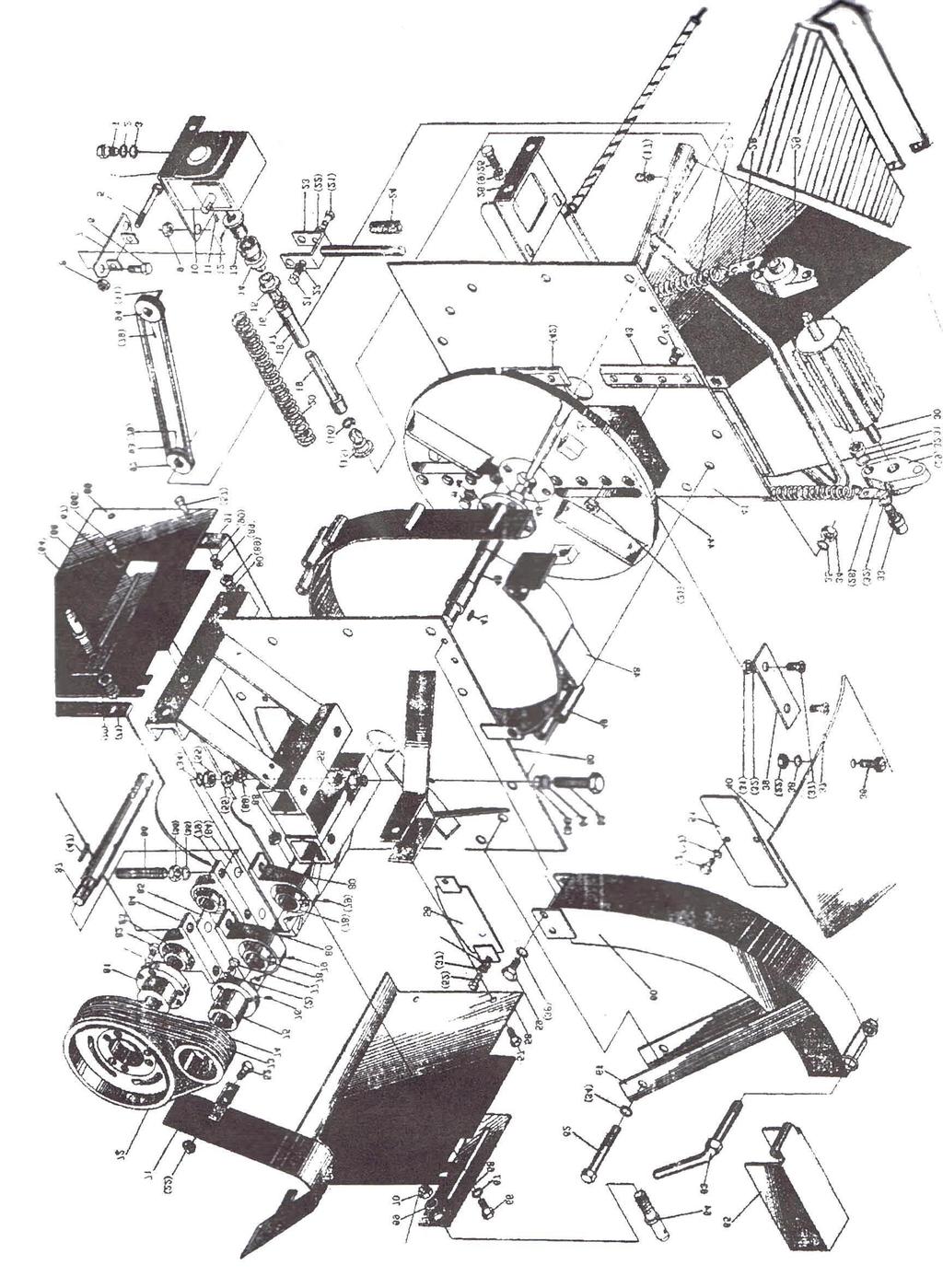
13 13
14 24 CHIPPER Sedal# Part# Description Qty. 1 GB/T x 8 Bolt 4 2 GB/T Washer 4 3 GB/T Washer 4 4 Gear box mounting plate 1 5 GB/T x 90 Bolt 1 6 GB/T x 25 Bolt PMF Release handle seat 1 8 GB/T Nut 1 9 GB/T Nut 4 10 Q/IAKY01-91 Worm reduction gear WPR40:30:1 II 1 11 GB/T x 20 Key 1 12 GB/T M6 x 20 Screw PMF Clutch inner claw PMF Clutch outer claw (24)PMF.217 Spring for drive knob 1 16 Gb/t Circlip 2 17 GB/T M6 oil cup PMF.034 Outer drive shaft PMF.033 Inner drive shaft PMF Spring for drive shaft 1 21 GB/T x 90 bolt 2 22 GB/T Nut PMF.035 Release handle PMF Main clutch handle 1 25 BG/T x 20 Bolt PMF.307 Gear box support plate PMF.109 Tension spring PMF.107 Spring Lug 2 29 UCFL Feed roll bearing PMF.021 Feed roll 1 31 GB/T M10 Nut GB/T Washer 8 14
15 24 CHIPPER Sedal# Part# Description Qty. 33 GB/T x 35 Bolt 4 34 GB/T x 1.5 Nut 3 35 GB/T Fender washer 2 36 GB/T M6 x 30 Screw 2 37 M10 x 27 Screw 8 38 GB/T M6 Washer PMF.104 Chipper Bed Blade 1 40 Plastic Plate PMF Strickle Assembly 1 42 M10x 27 Screw PMF.131 Chipper Blade PMF.130 Fly wheel 1 45 GB/T C6 x 20 Key PMF.023 Main Shaft Assembly 1 47 GB/T C10 x 50 Key PMF.013 Little Round Plate PMF.016 Outer Protective Cover Assembly PMF.017 Front Supportive Plate PMF.101 Rear Cover 1 52 GB/T x 12 Bolt 2 53 GB/T M14 x 1.5 x 50 bolt 4 54 GB/T M14 Washer GB/T M14 x 1.5 Nut PMF.011 Lower Cover 1 57 GB/T M10 x 25 Bolt PMF.101 Side Plate 1 59 GB/T M6 x 12 Bolt PMF.006 Discharge Pipe PMF.010 Support shelf, Discharge pipe 1 62 GB/T M14 x 140 Bolt PMF.013 Tightening Handle PMF.113 Connecting pin 2 15
16 24 CHIPPER Sedal# Part# Description Qty PMF.012 Protective Cover 1 66 GB/T M12 x 1.5 x 45 Bolt 4 67 GB/T M12 Washer PMF Front Connecting Plate 2 69 GB/T M22 Washer 2 70 GB/T M22 Nut PMF.020 Protective cover for pulley PMF Big Belt pulley PMF Small Belt pulley 1 74 Belt PMF.114 Small pulley hub 1 76 GB/T M6 x 16 Screw 2 77 GB/T M8 x 10 Bolt 3 78 GB/T Feed roll bearing GB/T M6 x 20 Screw 6 80 GB/T Stand base PMF.106 Big pulley hub 1 82 GB/T M10 x 50 Bolt 3 83 GB/T Feed roll bearing GB/T Stand base P PMF.102 Bearing seat shim PMF.106 Bearing seat adjustment screw PMF.108 Drive shaft 1 88 GB/T M10 Nut PMF.120 Side plate 1 90 GB/T M12 Washer PMF.111 Rear plate 1 92 Drive pulley of WRG 1 93 Belt 1 94 Drive pulley of WRG 1 16
17 Model WC-6 WC-8 Dimensions (l x w x h) 1600 x 1020 x 1400 mm 1600 x 1020 x 1400 mm Structure weight 370 kg 390 kg Blade turning radius 302 mm 302 mm Max diameter for wood 150 mm 200 mm Chipping efficiency 7~8m3/h 8~9m3/h PTO speed 540r/min 540r/min PTO spline 6 x 6 x x 6 x 520 Power required 18~45hp 25~45hp 17
Chipper/Shredder. Homier Distributing Company
 Chipper/Shredder 3175 Homier Distributing Company 84 Commercial Road Huntington, IN 46750 (800) 348-5004 Fax: 260-358-4159 www.homier.com or www.farmprotractors.com TABLE OF CONTENTS Page Introduction
WOOD CHIPPER WC1105 5PQ (8/08/2012)
") O P E R A T O R ' S M A N U A L WOOD CHIPPER WC1105 5PQ990102 (8/08/2012) To the Owner; Thank-You for choosing a quality product from Frontier Equipment. We strive to give you the best equipment and the
O P E R A T O R ' S M A N U A L WOOD CHIPPER WC1105 5PQ990102 (8/08/2012) To the Owner; Thank-You for choosing a quality product from Frontier Equipment. We strive to give you the best equipment and the
WOOD CHIPPER WC1103 5PQ (8/02/12)
") O P E R A T O R ' S M A N U A L WOOD CHIPPER WC1103 5PQ990101 (8/02/12) To the Owner; Thank-You for choosing a quality product from Frontier Equipment. We strive to give you the best equipment and the
O P E R A T O R ' S M A N U A L WOOD CHIPPER WC1103 5PQ990101 (8/02/12) To the Owner; Thank-You for choosing a quality product from Frontier Equipment. We strive to give you the best equipment and the
Wood Chipper Model C550M Operator's Manual
 Wood Chipper Model C550M Operator's Manual THIS MANUAL MUST BE READ AND UNDERSTOOD BEFORE ANYONE OPERATES THIS MACHINE! Manual# 990023 Revised 01/2010 YOU MUST FILL OUT YOUR WARRANTY REGISTRATION TO ACTIVATE
Maintenance and Repair
 Maintenance and Repair WARNING ALWAYS shut off the engine, remove key from ignition, make sure the engine is cool, and disconnect the spark plug and positive battery terminal from the battery before cleaning,
Wood Chipper Model C551H Operator's Manual
 Wood Chipper Model C551H Operator's Manual THIS MANUAL MUST BE READ AND UNDERSTOOD BEFORE ANYONE OPERATES THIS MACHINE! Manual# 990023 Revised 01/2010 YOU MUST FILL OUT YOUR WARRANTY REGISTRATION TO ACTIVATE
Champion Chippers OPERATOR S MANUAL. Operation & Safety. Includes Model: CX850 CX851. Part #
 OPERATOR S MANUAL Champion Chippers Operation & Safety Includes Model: CX850 CX851 Part # 990026 YOU MUST FILL OUT YOUR WARRANTY REGISTRATION TO ACTIVATE YOUR WARRANTY AND TO QUALIFY FOR PARTS SERVICE!!
OPERATORS MANUAL FOR KAFURTER ROTARY TOPPERS MODELS: TP110, TP140, TP160, TP170
 OPERATORS MANUAL FOR KAFURTER ROTARY TOPPERS MODELS: TP110, TP140, TP160, TP170 SAFETY WARNING: Do not use or operate this this manual and assembly instructions (where applicable) has been read and understood.
FLAIL MOWER SHREDDER
 FLAIL MOWER SHREDDER Operation, Service, & Parts Manual For Models: GML41, 49, 61, 69, & 79 February 2006 FORM: GMLMower.QXD TABLE OF CONTENTS Installation....................................................1
GROUNDSMASTER. 52 Recycler. for 120 Traction Unit. Model No & UP. Operator s Manual
 FORM NO. 8-980 Rev A GROUNDSMASTER 5 Recycler for 0 Traction Unit Model No. 077 79000 & UP Operator s Manual IMPORTANT: Read this manual carefully. It contains information about your safety and the safety
Finishing Mower Estate 72
 Finishing Mower Estate 72 Owners/Operators Manual & Spare Parts List Issue Date: October 2011 1 Introduction Your FIELDMASTER Estate 72 Finishing Mower has been designed to do a range of work to your satisfaction.
Fransgård. Manual GB V-4000 V Farm tractor winch
 Fransgård Manual GB Farm tractor winch V-4000 V-6500 Fransgård Maskinfabrik A/S Fredbjergvej 132 DK - 9640 Farsø Telefon : +45 98 63 21 22 Fax : +45 98 63 18 65 Web : www.fransgard.dk E-mail : info@fransgard.dk
HAMMER KNIFE FLAIL MOWER SHREDDER
 HAMMER KNIFE FLAIL MOWER SHREDDER Operation, Service, & Parts Manual For Models: GOL79 & GOL89 October 2010 FORM: GOLShredder.QXD TABLE OF CONTENTS Installation....................................................1
ROTARY TILLER. Operation, Service & Parts Manual For "AS" Series. FORM: ASTillerBook.QXD
 ROTARY TILLER Operation, Service & Parts Manual For "AS" Series FORM: ASTillerBook.QXD April 2002 TABLE OF CONTENTS Preparation......................................1 Assembly Instructions.............................2
tRIPr Chief Grain Cart. Operator s Manual. Operator s Manual
 125-000-01 125-000-01 1tRIPr 1tRIPr Operator s Manual 1210 Chief Grain Cart Operator s Manual Operator s Manual TO THE DEALER Predelivery/Delivery Checklist 1210 Grain Cart PREDELIVERY/DELIVERY CHECKLIST
42in GT Classic Single Stage Snowthrower Conversion Kit XT Series Garden Tractor
 Form No. 9 66 in GT Classic Single Stage Snowthrower Conversion Kit XT Series Garden Tractor Part No. 06 88 Installation Instructions English (EN) This kit is for installing an existing 00 Series Classic
DM-135 DRUM MOWER USER S MANUAL
 DM-135 DRUM MOWER USER S MANUAL 1 DM135 DRUM MOWER INSTRUCTIONS CHAPTER 1 SAFE OPERATION Do not attempt to operate the mower until you have read the operator s manual and all the safety signs on the mower.
ProLine. 44 Mower. for 120 Traction Unit. Model No & Up. Operator s Manual
 FORM NO. 9 ProLine Mower for 0 Traction Unit Model No. 05 99000 & Up Operator s Manual IMPORTANT: Read this manual carefully. It contains information about your safety and the safety of others. Also become
ROTARY MOWER OPERATION, SERVICE & PARTS MANUAL FOR
 ROTARY MOWER OPERATION, SERVICE & PARTS MANUAL FOR L-G-40-40-P, L-G-48-40-P, L-G-60-40-P & L-G-72-40-P Slip Clutch Models: L-G-60-40-SC-P & L-G-72-40-SC-P February 2003 FORM: RotMwrBook.QXD TABLE OF CONTENTS
Post Hole Diggers Compact Standard Heavy Duty
 Post Hole Diggers Compact Standard Heavy Duty MODEL 90 / MODEL 100 / MODEL 110 # 100623 # 100498 # 100624 Operation Manual This safety alert symbol identifies important safety messages in this manual.
Post Hole Digger. Operation Manual MODEL
 Post Hole Digger MODEL 107798 Operation Manual This safety alert symbol identifies important safety messages in this manual. Failure to follow this important safety information may result in serious injury
Table of Contents. Safety symbols... 3 Assembly 6. Operation Maintenance Troubleshooting 11. Storage. 12. Notes. 13
 Table of Contents Safety symbols... 3 Assembly 6 Operation... 8 Maintenance... 10 Troubleshooting 11 Storage. 12 Notes. 13 2 Safety Information Attention; this machine can be dangerous! All operators should
3 POINT HITCH WOOD CHIPPER MODEL BX-42 (VC-40)
") 3 POINT HITCH WOOD CHIPPER MODEL BX-42 (VC-40) OPERATOR S MANUAL & SPARE PARTS LIST 1. INTRODUCTION Congratulations on your choice of a FIELDMASTER 3 Point Hitch Wood Chipper to compliment your operation.
3 POINT HITCH WOOD CHIPPER MODEL BX-42 (VC-40) OPERATOR S MANUAL & SPARE PARTS LIST 1. INTRODUCTION Congratulations on your choice of a FIELDMASTER 3 Point Hitch Wood Chipper to compliment your operation.
HAMMER KNIFE FLAIL MOWER SHREDDER
 HAMMER KNIFE FLAIL MOWER SHREDDER Operation, Service, & Parts Manual For Models: GOF69, 79, 89, 98, & 108 February 2006 Rev. 2009 FORM: GOFMower.QXD TABLE OF CONTENTS Installation....................................................1
WOOD CHIPPER. Operation, Service, & Parts Manual For Model 420. June Form: 420Chipper.indd
 WOOD CHIPPER Operation, Service, & Parts Manual For Model 420 June 2008 Form: 420Chipper.indd TABLE OF CONTENTS PAGE General Information... 1-2 Introduction...2 Symbols...2 Safety Labels... 3-4 Technical
2. PREPARATION 1. SAFETY 3. FRAME 4. TRANSMISSION 5. DRIVE 6. ROW UNIT 7. OPTIONAL EQUIPMENT Monosem Inc.
 TABLE OF CONTENTS 1. SAFETY 2. PREPARATION 3. FRAME 4. TRANSMISSION 5. DRIVE 6. ROW UNIT 7. OPTIONAL EQUIPMENT For the initial preparation of the planter, lubricate the planter and row units. Make sure
Operator s Manual SB /2014. Straw Blower
 R R Operator s Manual SB 5400 9/2014 Thank you for purchasing a Harper. As with all Harper products, the has been developed through tough design and testing procedures to produce a top quality machine.
THE GIANT-VAC PTO BLOWER MODELS 2000*/3200**/4000***
 THE GIANT-VAC PTO BLOWER MODELS 2000*/3200**/4000*** Congratulations! ASSEMBLY INSTRUCTIONS AND OPERATOR S MANUAL You have just purchased one of the finest pieces of outdoor power equipment on the market
W & A 12 ROW TOP LEVELING STACKER LEVEL BANDER
 W & A 12 ROW TOP LEVELING STACKER LEVEL BANDER NO. 3640 OPERATOR S MANUAL TO THE OWNER: Congratulations on your purchase of a new W & A Top Leveling Stacker Level Bander. Your selection is an indication
Operator's Manual. VC-60 & VC-60 Plus Harper Industries, Inc. 7/03 Part No
 Operator's Manual VC-60 & VC-60 Plus 2003 Harper Industries, Inc. 7/03 Part No. 970066 Thank you for purchasing a Harper/Goossen Verti-Cutter. As with all Harper/Goossen products, the Harper/Goossen Verti-Cutter
42in GT Classic Single Stage Snowthrower Conversion Kit XT Series Garden Tractor
 Form No. 5 70 in GT Classic Single Stage Snowthrower Conversion Kit XT Series Garden Tractor Part No. 06 858 Installation Instructions Original Instructions (EN) This kit is for installing an existing
SECTION V ASSEMBLY CAUTION THE FOLLOWING SAFETY PRECAUTIONS SHOULD BE THOROUGHLY UNDERSTOOD BEFORE ATTEMPTING MACHINE ASSEMBLY.
 SECTION V ASSEMBLY CAUTION THE FOLLOWING SAFETY PRECAUTIONS SHOULD BE THOROUGHLY UNDERSTOOD BEFORE ATTEMPTING MACHINE ASSEMBLY. 1. Wear personal protective equipment such as, but not limited to protection
TL SERIES ADJUSTABLE OFFSET TILLER
 R L S E S 995 OPERATION & PARTS MANUAL Please read these instructions carefully before using! Always grease all fittings and be sure to always check and fill with oil before operating! Retain this manual
Operating and Assembly Manual
 Model CV385-PRO Operating and Assembly Manual Midwest Equipment Manufacturing, Inc. 5225 Serum Plant Road Thorntown, IN 46071 2-09-16 SAFETY RULES Remember, any power equipment can cause injury if operated
POST HOLE DIGGER. Operation, Service & Parts Manual For Models D20 & D40. FORM: D20_40DigRev.QXD
 POST HOLE DIGGER Operation, Service & Parts Manual For Models D20 & D40 FORM: D20_40DigRev.QXD September 2006 Revised August 2009 TABLE OF CONTENTS Introduction.............................1 Preparation..............................2
Straw Blower 5400 OPERATOR S MANUAL. Straw Blower
 5400 OPERATOR S MANUAL 7-2015 Thank you for purchasing a Harper. As with all Harper products, the has been developed through tough design and testing procedures to produce a top quality machine. This
ROTARY TILLER. Operation, Service & Parts Manual For P-P/C Series. November 1996 (Rev. 4-05) FORM: PTillerBook.QXD
 FORM: PTillerBook.QXD") ROTARY TILLER Operation, Service & Parts Manual For P-P/C Series FORM: PTillerBook.QXD November 1996 (Rev. 4-05) TABLE OF CONTENTS Preparation......................................1 Assembly Instructions.............................2
ROTARY TILLER Operation, Service & Parts Manual For P-P/C Series FORM: PTillerBook.QXD November 1996 (Rev. 4-05) TABLE OF CONTENTS Preparation......................................1 Assembly Instructions.............................2
WARRANTY REGISTRATION AND POLICY
 WARRANTY REGISTRATION AND POLICY Buhler Manufacturing products are warranted for a period of twelve (12) months from original date of purchase, by original purchaser, to be free from defects in material
POWER FEED WOOD CHIPPER
 POWER FEED WOOD CHIPPER Operation, Service, & Parts Manual For Model 520 October 2009 Form: 520Chipper.indd TABLE OF CONTENTS PAGE General Information... 1-2 Introduction...2 Symbols...2 Safety Labels...
2. PREPARATION 1. SAFETY 3. FRAME 4. TRANSMISSION 5. DRIVE 6. ROW UNIT 7. OPTIONAL EQUIPMENT
 TABLE OF CONTENTS 1. SAFETY 2. PREPARATION 3. FRAME 4. TRANSMISSION 5. DRIVE 6. ROW UNIT 7. OPTIONAL EQUIPMENT For the initial preparation of the planter, lubricate the planter and row units. Make sure
Z Master. 62 Mower. for Z Master Z 255 Traction Unit. Model No & UP. Operator s Manual
 FORM NO. 9 88 Z Master 6 Mower for Z Master Z 55 Traction Unit Model No. 7408 89000 & UP Operator s Manual IMPORTANT: Read this manual carefully. It contains information about your safety and the safety
p.t.o. Slip clutch Read this material before using this product. Failure to do so can result in serious injury. Save this manual.
 p.t.o. Slip clutch 65517 Installation Instructions Distributed exclusively by Harbor Freight Tools. 3491 Mission Oaks Blvd., Camarillo, CA 93011 Visit our website at: http://www.harborfreight.com Read
KING COBRA/CALIBER GRASS COLLECTION SYSTEM PARTS & OPERATORS MANUAL
 KING COBRA/CALIBER GRASS COLLECTION SYSTEM PARTS & OPERATORS MANUAL GRASS CATCHER W/WEIGHTS: TUBE KITS: BLOWER KITS: 52 542128 52 542119 5101002 60 542129 60 542120 5101003 2 WORLDLAWN POWER EQUIPMENT
Wheel Horse. 36 Tiller. Model No & Up. Operator s Manual
 FORM NO. 8 9 Rev. A Wheel Horse 6 Tiller for Classic Garden Tractors Model No. 7970 690000 & Up Operator s Manual IMPORTANT: Read this manual carefully. It contains information about your safety and the
Wheel Horse. 44 Snowthrower. for 5xi Lawn and Garden Tractors. Model No & Up. Operator s Manual
 FORM NO. 8 Rev A Wheel Horse Snowthrower for 5xi Lawn and Garden Tractors Model No. 7966 890050 & Up Operator s Manual IMPORTANT: Read this manual, and your tractor manual, carefully. They contain information
TJ lb Capacity Trailer Jack. 2-in-1 Combo With Swing Back Design. Assembly & Operating Instructions
 TJ1500 1500 lb Capacity Trailer Jack 2-in-1 Combo With Swing Back Design Assembly & Operating Instructions READ ALL INSTRUCTIONS AND WARNINGS BEFORE USING THIS PRODUCT. This manual provides important information
Centrifugal PTO Pumps. 2 nd Edition
 Centrifugal PTO Pumps 2 nd Edition MAN072 November 2005 2005 Centrifugal PTO pumps are manufactured by AMADAS Industries. You can find us on the Web at: www.amadas.com or e-mail us at: amadas@amadas.com
Operating and Assembly Manual
 Model 1080 Operating and Assembly Manual Midwest Equipment Manufacturing, Inc. 5225 Serum Plant Road Thorntown, IN 46071 08-02-16 SAFETY RULES Remember, any power equipment can cause injury if operated
OPE R AT O R S MANU A L QUICK-HITCH ADAPTER. 5BP (Field conversion kit)
") OPE R AT O R S MANU A L 5BP006750 (Field conversion kit) Manual 5BP97378B Date 06/8/05 SAFETY Take note! This safety alert symbol found throughout this manual is used to call your attention to instructions
OPE R AT O R S MANU A L 5BP006750 (Field conversion kit) Manual 5BP97378B Date 06/8/05 SAFETY Take note! This safety alert symbol found throughout this manual is used to call your attention to instructions
DIAMONDBACK/EDGE GRASS COLLECTION SYSTEM PARTS & OPERATORS MANUAL
 DIAMONDBACK/EDGE GRASS COLLECTION SYSTEM PARTS & OPERATORS MANUAL GRASS CATCHER W/WEIGHT: TUBE KIT: BLOWER KIT: 48 5101305 632093 632078 52 5101305 542119 632074 60 632086 542120 632081 3 WORLDLAWN POWER
4815RR1,4810RR RR1,14810RR1
 4815RR1,4810RR1 14815RR1,14810RR1 This Manual applies to Models: 4815RR1, 4810RR1, 14815RR1, 14810RR1 FLEX-WING ROTARY CUTTERS / SHREDDERS Published 07/16 Part No. 50076491 To the Owner/Operator/Dealer
610 BUSHEL MANURE SPREADER
 610 BUSHEL MANURE SPREADER RODA MANUFACTURING 1008 LOCUST ST. HULL, IA. 51239 Art s-way Manufacturing 712-439-2366 Co., Inc. Hwy 9 West - PO Box 288 WWW.RODAMFG.COM Armstrong, IA. 50514 U.S.A 2 INTRODUCTION
SAFETY SAFETY CABLE INSTALLATION /00 1 of 6
 SAFETY DO NOT INSTALL, OPERATE OR USE THIS EQUIPMENT UNTIL THE FOLLOWING OPERATING AND SAFETY INSTRUCTIONS HAVE BEEN READ AND UNDERSTOOD. This symbol is used to bring attention to safety precautions and
OPERATOR S MANUAL. 20-bu 3-Point Hitch Material Collection System. LP65048 Supplier ST /07/2017 English. North American Edition Printed in USA
 OPERATOR S MANUAL 20-bu 3-Point Hitch Material Collection System LP65048 Supplier ST48289 11/07/2017 English North American Edition Printed in USA Introduction Using Your Operator s Manual Read this entire
TABLE OF CONTENTS DESCRIPTION. Safety Instructions & Safety Sign Locations Operating Instructions Assembly Instructions...
 TABLE OF CONTENTS DESCRIPTION PAGE Warranty... 1 Safety Instructions & Safety Sign Locations... 2 Operating Instructions... 3 Assembly Instructions... 5 500 & 600 Snowblower Drawings... 8 500 & 600 Snowblower
GRASS CATCHER PART S & OPERATORS MANUAL
 GRASS CATCHER PART S & OPERATORS MANUAL WORLDLAWN POWER EQUIPMENT, INC. WORLDLAWN.COM 2415 ASHLAND AVE BEATRICE, NE 68310 800-267-4255 FAX 402-223-4103 2 3 4 OPERATORS MANUAL This catcher manual is for
ACCLAIM OPERATOR, PARTS, AND INSTALLATION MANUAL BX4330 ACCLAIM
 ACCLAIM OPERATOR, PARTS, AND INSTALLATION MANUAL BX4330 ACCLAIM Tow Bar Class III (5000 lb) 2 Inch Coupler TOWING PRODUCTS DIVISION Page 1 of 8 292-2205 4/23/09 SAFETY DO NOT INSTALL, OPERATE OR USE THIS
44 and 52 Twin Bagger 100 Series Z Master
 Form No. 7 87 and 5 Twin Bagger 00 Series Z Master Model No. 7855 Serial No. 000000 and Up Operator s Manual English (CE) Contents Page Introduction................................ Safety.....................................
MK AUGERS POWER SWING KIT ASSEMBLY & OPERATION MANUAL
 MK AUGERS POWER SWING KIT ASSEMBLY & OPERATION MANUAL Read this manual before using product. Failure to follow instructions and safety precautions can result in serious injury, death, or property damage.
ATTACHMENTS COMPONENT LOCATION
 42-Inch Mower Deck ATTACHMENTS COMPONENT LOCATION C D E F G H I H G M A B J O K L N M J A - Gage Wheel (Left Front) B - Belt Cover C - Primary Drive Belt D - Flat Idler (fixed) E - Gage Wheel (Right Front)
BEFCO. Operator s Manual BABY HOP & HOP FERTILIZER SPREADERS ACCESSORIES SIDE ROW DISCHARGE. AA4-120 (fits models Hop 209 & 212) DEFLECTOR
 DEFLECTOR") BEFCO Operator s Manual BABY HOP & HOP FERTILIZER SPREADERS ACCESSORIES SIDE ROW DISCHARGE AA-0 (fits models Hop 09 & ) DEFLECTOR AA-0 (fits models Baby Hop 0 & 06) 009-95 (fits models Hop 0 & 06) 009-968
BEFCO Operator s Manual BABY HOP & HOP FERTILIZER SPREADERS ACCESSORIES SIDE ROW DISCHARGE AA-0 (fits models Hop 09 & ) DEFLECTOR AA-0 (fits models Baby Hop 0 & 06) 009-95 (fits models Hop 0 & 06) 009-968
Operating and Assembly Manual
 Model 455-IC/PRO/H Operating and Assembly Manual Midwest Equipment Manufacturing, Inc. 5225 Serum Plant Road Thorntown, IN 46071 03-08-12 SAFETY RULES Remember, any power equipment can cause injury if
OPERATOR and PARTS MANUAL GRAIN GRINDER MODEL GG 10
 1 Serial # GG10-AUG10-6-0701 to GG10-AUG10-276-0314 ROTO GRIND OPERATOR and PARTS MANUAL GRAIN GRINDER MODEL GG 10 ROTO GRIND BURROWS ENTERPRISES, INC. 2024 East 8 th Street Greeley, Colorado 80631 970-353-3769
57 ROUGH CUT OWNER S MANUAL. With Assembly Instructions For Model: MR55H KUNZ ENGINEERING, INC. / MENDOTA, IL / PH (815) /07
 /07") 57 ROUGH CUT OWNER S MANUAL With Assembly Instructions For Model: MR55H KUNZ ENGINEERING, INC. / MENDOTA, IL 61342 / PH (815) 539-6954 1/07 ASSEMBLY INSTRUCTIONS Read the complete assembly instructions
57 ROUGH CUT OWNER S MANUAL With Assembly Instructions For Model: MR55H KUNZ ENGINEERING, INC. / MENDOTA, IL 61342 / PH (815) 539-6954 1/07 ASSEMBLY INSTRUCTIONS Read the complete assembly instructions
CPHD POST HOLE DIGGER Operator s/parts Manual. Table of Contents
 CPHD POST HOLE DIGGER Operator s/parts Manual Table of Contents Warranty Information... -3 Dealer Checklist... 4 Safety Precautions... 5-6 Federal Laws and Regulations... 7 Torque Specifications... 8 Important
DWHOIST. Drywall Hoist Assembly & Operating Instructions
 DWHOIST Drywall Hoist Assembly & Operating Instructions READ ALL INSTRUCTIONS AND WARNINGS BEFORE USING THIS PRODUCT. SAVE THESE INSTRUCTIONS FOR FUTURE REFERENCE. This manual provides important information
LORENZ SNOW BLOWER 310 SERIES
 Owner s and Parts Manual LORENZ SNOW BLOWER 30 SERIES (530, 630, 730) LORENZ MFG. CO. 5 30 TH AVENUE SE BENSON MN 565 --3-30 lorenzmfg.com May 00 Contents Page Introduction Safety Specifications Unpacking
EFGC Series Flail Mower Assembly/Operations/Parts Manual
 EFGC Series Flail Mower Assembly/Operations/Parts Manual Betst Power Equipment 1-877-876-7895 Support@Betstco.com Table of Contents 1. Introduction 3 2. Setup and Assembly Instructions 3 3. PTO Driveshaft
Operating and Assembly Manual
 Model 455-IC/PRO/H Operating and Assembly Manual Palmor Products Inc. 5225 Serum Plant Road Thorntown, IN 46071 03-08-12 SAFETY RULES Remember, any power equipment can cause injury if operated improperly
57 ROUGH CUT WITH ELECTRIC CLUTCH BLADE ENGAGEMENT OWNER S MANUAL. With Assembly Instructions For Model: MR55KE
 57 ROUGH CUT WITH ELECTRIC CLUTCH BLADE ENGAGEMENT OWNER S MANUAL With Assembly Instructions For Model: MR55KE KUNZ ENGINEERING, INC. / MENDOTA, IL 61342 / PH (815) 539-6954 01/05 ASSEMBLY INSTRUCTIONS
Model 858-RH. Operating and Assembly Manual. Palmor Products Inc Serum Plant Road Thorntown, IN 46071
 Model 5-RH Operating and Assembly Manual Palmor Products Inc. 55 Serum Plant Road Thorntown, IN 6071 3/31/015 SAFETY RULES Remember, any power equipment can cause injury if operated improperly or if the
Wheel Horse. 42 Mower. for Lawn and Garden Tractors. Model No & Up. Operator s Manual
 FORM NO. 9 559 Rev A Wheel Horse 4 Mower for Lawn and Garden Tractors Model No. 78 890000 & Up Operator s Manual IMPORTANT: Read this manual carefully. It contains information about your safety and the
RED23305 Owner s Manual
 RED23305 Owner s Manual 5 foot, 3-Point Mounted Snow Blower 270 West Park Avenue Huron, SD 57350 866-526-5682 Serial Number: Date of Purchase: Red Devil Snow Blower See Figure 1. 1. The Red Devil Snow
36 Tiller Wheel Horse Lawn and Garden Tractor Attachment
 Form No. 9 6 Rev B 6 Tiller Wheel Horse Lawn and Garden Tractor Attachment Model No. 797 890000 and Up Operator s Manual English(En) Contents Page Introduction................................ Safety.....................................
DEBRIS BLOWER 3600 OPERATOR S MANUAL. Debris Blower
 DEBRIS BLOWER 3600 OPERATOR S MANUAL 9-208 Thank you for purchasing a Harper. As with all Harper products, the has been developed through tough design and testing procedures to produce a top quality machine.
FERTILIZER SPREADERS MODEL PL180, PL400 & PL500
 FERTILIZER SPREADERS MODEL PL180, PL400 & PL500 SAFETY INSTRUCTIONS; OPERATING INSTRUCTIONS; PARTS BREAKDOWNS; ASSEMBLY; MAINTENANCE TABLE OF CONTENTS PAGE Introduction...1 Safety Decals...2 Checklists...3
OPERATOR and PARTS MANUAL GRAIN GRINDER MODEL GG 7
 1 Serial # GG7-AUG10-71-1013 and Higher 2014 and up ROTO GRIND OPERATOR and PARTS MANUAL GRAIN GRINDER MODEL GG 7 ROTO GRIND BURROWS ENTERPRISES LLC 2024 East 8 th Street Greeley, Colorado 80631 970-353-3769
SECTION SAFETY AFTERMARKET PRODUCT GUIDE SAFETY
 AFTERMARKET PRODUCT GUIDE 1 2 WARNING! Be certain to disengage PTO shaft and to turn off the tractor before making any operational maintenance inspections or repairs. Keep clear of the machine until all
OPERATOR, PARTS AND INSTALLATION MANUAL. BX7330 AVENTA TM Tow Bar TOWING PRODUCTS DIVISION
 A V E N T A TM OPERATOR, PARTS AND INSTALLATION MANUAL BX7330 AVENTA TM Tow Bar TOWING PRODUCTS DIVISION SAFETY DO NOT INSTALL, OPERATE OR USE THIS EQUIPMENT UNTIL THE FOLLOWING OPERATING AND SAFETY INSTRUCTIONS
48 Side Discharge Mower
 FORM NO. 9 650 Rev A Wheel Horse 8 Side Discharge Mower for Classic Garden Tractor Model No. 786 890000 & Up Operator s Manual IMPORTANT: Read this manual carefully. It contains information about your
CALL TOLL FREE FAX:
 ADAMS FERTILIZER EQUIPMENT BUCKET ELEVATOR PARTS MANUAL CALL TOLL FREE -800-643-466 870-946-494 FAX: 870-946-4396 WEBSITE: www.adamsfertequip.com EMAIL: adams@adamsfertequip.com Belt Overlap Assembly Nylon
DFS Vac Collection System 400 Series Z Master
 Form No. 0 DFS Vac Collection System 00 Series Z Master Model No. 780 Serial No. 000000 and Up Operator s Manual Register your product at www.toro.com Original Instructions (EN/GB) Contents Page Introduction................................
DEBRIS BLOWER 2700 OPERATOR S MANUAL. Debris Blower
 DEBRIS BLOWER 2700 OPERATOR S MANUAL 6-2015 Thank you for purchasing a Harper. As with all Harper products, the has been developed through tough design and testing procedures to produce a top quality
OPERATOR S MANUAL & PARTS LIST
 OPERATOR S MANUAL & PARTS LIST Flail Mower MODEL FL-72 FIRST PRODUCTS INC. 164 Oakridge Church Road Tifton, Georgia 31794 U.S.A. Phone (229) 382-4768 1-800-363-8780 Fax (229) 382-0506 Web: www.1stproducts.com
3 POINT HITCH CHIPPER-SHREDDER MODEL BXM32 & BXM42
 BY EMB MFG INC. EMB Manufacturing Inc. 4144 Boomer Line St. Clements, On N0B 2M0 Canada Ph: (519) 699-9283 Fax: (519) 699-4146 www.embmfg.com BXM32 BXM42 3 POINT HITCH CHIPPER-SHREDDER MODEL BXM32 & BXM42
Operating and Assembly Manual
 Model 470-/H/PRO/IC Operating and Assembly Manual Midwest Equipment Manufacturing, Inc. 5225 Serum Plant Road Thorntown, IN 46071 11-11-11 SAFETY RULES Remember, any power equipment can cause injury if
BWC-040 BWC-060. Wood Chipper. Operator s Manual Parts Breakdown
 BWC-040 BWC-060 Wood Chipper Operator s Manual Parts Breakdown Publication #: November 2013 TABLE OF CONTENTS Introduction 3 Safety 3 Safety Signal Words 4 General Safety Guidelines 4 Safety Decal Care
57 ROUGH CUT OWNER S MANUAL. With Assembly Instructions. For Models: MR55T, MR55B-17.5HP, MR55B-22HP & MR55K
 57 ROUGH CUT MR55K MR55B OWNER S MANUAL With Assembly Instructions For Models: MR55T, MR55B-17.5HP, MR55B-22HP & MR55K KUNZ ENGINEERING, INC. / MENDOTA, IL 61342 / PH (815) 539-6954 1/07 ASSEMBLY INSTRUCTIONS
PRODUCT MANUAL TILE CUTTING MACHINE. . Operation. Parts List and Diagram SPECIFICATIONS CAUTION:
 FLORCRAFTT TM PRODUCT MANUAL SKU NUMBER 709-4242 SERIAL NUMBER: CAUTION: FOR YOUR OWN SAFETY READ INSTRUCTION MANUAL COMPLETELY AND CAREFULLY BEFORE OPERATING THIS 7 TILECUTTING MACHINE SPECIFICATIONS
Tube-Line Bale Processor Boss II
 Tube-Line Bale Processor Boss II Operator's Manual 28686 (13/08/13) BOSS TWO SQUARE BALE PROCESSOR INTRODUTION Your BOSS TWO SQUARE BALE PROCESSOR is designed to load and shred all types of forage in large
CS HP CHIPPER SHREDDER
 CS-65 6.5HP CHIPPER SHREDDER OPERATION MANUAL IMPORTANT READ CAREFULLY BEFORE USE KEEP FOR FUTURE REFERENCE Attn: users. We are highly appreciated for your using CS-65 shredder. Read this operation manual
42 Mower Wheel Horse Classic Garden Tractor Attachment
 Form No. 6 9 Mower Wheel Horse Classic Garden Tractor Attachment Model No. 78 000000 and Up Operator s Manual Domestic English (EN) Contents Page Introduction................................ Slope Chart..............................
North Dakota State University Grounds Maintenance Equipment
 North Dakota State University Grounds Maintenance Equipment I. Introduction Grounds maintenance equipment is an important part of the work activities on NDSU campus. They can make grounds maintenance jobs
ASSEMBLY INSTRUCTIONS
 ASSEMBLY INSTRUCTIONS Read the complete assembly instructions before starting the assembly. You should have: - one mower deck assembly - two carrier arm assemblies - two rear tire assemblies - one ATV
HORSTMAN GREASED LIGHTNING CLUTCH
 HORSTMAN GREASED LIGHTNING CLUTCH Horstman s Greased Lightning (GL) clutch is designed for ultra high performance, and requires expert setup and a serious commitment to maintenance. Warning!!! 1. Clutch
48 Mower Wheel Horse Classic Garden Tractor Attachment
 Form No. 6 96 Rev B 8 Mower Wheel Horse Classic Garden Tractor Attachment Model No. 786 000000 and Up Operator s Manual Domestic English (EN) Contents Page Introduction.................................
57 ROUGH CUT OWNER S MANUAL. With Assembly Instructions For Models: MR55T, MR55B & MR55K
 57 ROUGH CUT MR55K MR55B OWNER S MANUAL With Assembly Instructions For Models: MR55T, MR55B & MR55K KUNZ ENGINEERING, INC. / MENDOTA, IL 61342 / PH (815) 539-6954 1/05 ASSEMBLY INSTRUCTIONS Read the complete
Quiet Collector. Model No & Up
 FORM NO. -0 Quiet Collector Model No. 79-990000 & Up Operator s Manual IMPORTANT: Read this manual, and your tractor manual, carefully. They contain information about your safety and the safety of others.
52 inch Twin Bagger and Finishing Kit 200 Series Z Master
 Form No. 9 68 inch Twin Bagger and Finishing Kit 00 Series Z Master Model No. 7898 Serial No. 000000 and Up Model No. 780 Operator s Manual English (EN) Contents Page Introduction................................
BX42 SERIES WOOD CHIPPERS
 BX42 SERIES WOOD CHIPPERS OPERATION & PARTS MANUAL Please read these instructions carefully before using! Always grease all fittings and be sure to always check and fill with oil before operating! Retain