Starting Combinations
|
|
|
- Michael Preston
- 5 years ago
- Views:
Transcription

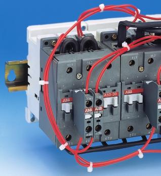
1 Main Catalogue Starting Combinations
2 Motor Nominal Powers and Currents The currents given below concern standard, r.p.m. 50 Hz, three-phase cage motors. These values are for your information and may vary according to the motor manufacturer and depending on the number of poles. Motor power Motor nominal current at: 380 V 415 V 440 V 500 V 600 V V V kw PS = hp A A A A A A / / / / / / / /0 ABB Control
3 Starting Combinations 1 Contents Panorama... 1/2 General Information Direct Starting... 1/4 Star-Delta Starting... 1/5 Co-ordination with SCPD... 1/6 Utilization Categories... 1/7 CE Marking, Machine Directive... 1/8 Degrees of Protection... 1/9 Open type Starters... Sections Enclosed Starters... Sections ABB Control 1/1
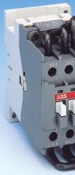
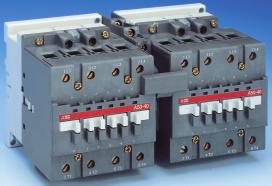
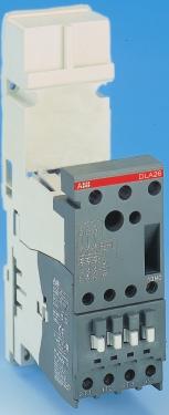
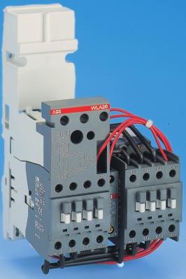
4 Open Type Starters Protection by Thermal O/L Relay YKA..-30 VOA..-30M 3-phase motor 1 operating direction 2 operating directions Starting Star-delta Direct Mains changeover contactors Rated operational current (400 V) Rated operational power 170 A AC A AC A AC-1 90 kw 55 kw Starter type YKA..-30 / YDA..-30 / YKA..-30E VOA..-30M / VNA..-30M VOA..-40Z Thermal O/L relay TA... (order separately) Section Protection by associated manual motor starter 3-phase motor 1 operating direction 2 operating directions Starting Direct Rated operational current (400 V) Rated operational power 25 A AC-3 11 kw Starter type DLA..-30 WLA..-30 Manual motor starter MS (order separately) Section 5 6 1/2 ABB Control
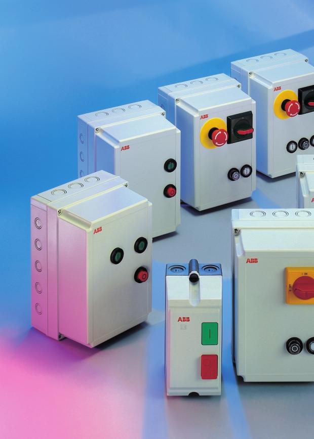
5 Enclosed Starters Protection by thermal O/L relay DYA YRA WRA 3-phase motor 1 operating direction 2 operating directions Starting Direct Star-delta Direct Rated operational current (400 V) Rated operational power 110 A AC A AC A AC-3 55 kw 90 kw 55 kw Starter type DWA / DYA / DRA / DEA YRA / YEA WRA / WEA Thermal O/L relay TA... (order separately) Section Protection by associated manual motor starter DRA D YRA DB WRA DB+BU 3-phase motor 1 operating direction 2 operating directions Starting Direct Star-delta Direct Rated operational current (400 V) Rated operational power 25 A AC-3 11 kw Starter type DRA D / DRA DB / DRA DB+BU YRA D / YRA DB / YRA DB+BU WRA D / WRA DB / WRA DB+BU Starting type MS (factory mounted) D : Emergency stop by manual motor starter handle DB : Emergency stop by manual motor starter handle - Undervoltage coil DB+BU : Emergency stop by mushroom headed button - Undervoltage coil Section ABB Control 1/3
6 D.O.L. Starting of Three-Phase Asynchronous Motors General A combination starter performs the following functions: circuit isolation and short-circuit protection, motor "ON" - "OFF" control, overload protection. The isolation and short-circuit protection functions must be performed by a fuse isolator switch, a fuse switch or a circuit-breaker. Fuse ratings recommended in this document should be used. The "ON" - "OFF" control and overload protection functions are performed by a contactor and thermal O/L relay combination. Full voltage D.O.L. starting is a simple, economic solution characterised by a high starting torque (1.9 to 2.1 times full-speed torque) and a starting current 5.5 to 7 times nominal current. I /I n C /C n 7 6 I = current; I n = nominal current C = torque; C n = nominal torque I C 1 Nominal values A1011DG Motor speed (%) 1/4 ABB Control
7 Star-Delta Starting of Three-Phase Asynchronous Motors General On starting, the motor has to overcome the resistive torque and inertia of the driven machine. During this phase, current must remain within the limits acceptable by the mains. 1 Inertia, resistive torque and mains are commonly fixed data. Although the type of starting reduces the inrush current as required, it also reduces the torque supplied by the motor. The result is a speed buildup time that varies according to the starting process used. Star-delta starting I /I n C /C n I = current; I n = nominal current C = torque; C n = nominal torque I (delta) I (star) C (motor) Technical Data On starting: current inrush is reduced to a third of direct starting current, motor torque is reduced to a third of direct starting torque. High transient currents are commonly read during star-delta switching. Utilization During the initial starting phase ("star" connection), the resistive torque of the driven machine must remain, irrespective of speed, less than the "star" motor torque until "star-delta" switching occurs. This starting mode is therefore ideal for machines with no-load starting and little inertia: machine-tools, centrifugal compressors, wood working machines, etc. In order to prevent an over high current peak, at least 80% of nominal speed must be reached on "star-delta" switching. 1 0 C (motor) C r (resistive torque) Motor speed (%) E0899DG Precautions Motor nominal voltage in delta connection must be equal to that of the mains. Example: A motor for 380 V star-delta starting must be designed for 380 V in "delta" connection. Its usual designation is "380 V/660 V motor". The motor must be constructed with 6 terminal windings. Operation Starting is a three-stage process: 1st stage - "Star" connection Press the "On" button on the control circuit to close the KM2 "star" contactor. The KM1 "line" contactor then closes and the motor starts. Countdown of programmed starting time (normally 6 to 10 s) then begins. 2nd stage - "Star" to "delta" switching When the programmed starting time is up, the KM2 "star" contactor opens. 3rd stage - "Delta" connection After 50 ms have elapsed, the KM3 "delta" contactor closes, and the motor accelerates until it reaches nominal speed. Note: the 50 ms period elapsing between opening of the "star" contactor and closing of the "delta" contactor prevents arc short-circuits. ABB Control 1/5
8 General Information Co-ordination with SCPD 3 Co-ordination M 3 E0518D In compliance with standards IEC and EN , we define for the contactors and starters the type, rating and characteristics of the short-circuit protection devices SCPD wich allow selective protection against overloads and ensure protection against short circuits. Basic Functions In order to protect the connecting cable and the motor, the switchgear must ensure the four following essential functions: Protection against overloads - This protection concerns the motor and the cable and is ensured by the starter overload relay. Motor control - This function is commonly carried out by the contactor. Protection against short-circuits. Isolation. The latter two functions can be carried out by a circuit-breaker or by a switch-disconnector-fuse protecting the motor and the cable against short circuits and ensuring isolation with positive contact indication. Applicable Standards IEC (EN ) precisely defines the different points to be considered in order to carry out correct co-ordination. Complete co-ordination for a combination includes the following points: Selectivity test between the overload relay and the short-circuit protection device SCPD. Short-circuit condition tests: at prospective "r" currents - These currents depend on the rated operational current of the starter (I e AC-3) and are given by the standard (Table XI). For example: r = 1kA for I e AC-3 < 16 A; r = 3 ka for 16 A < I e AC-3 < 63 A ; r = 5 ka for 63 A < I e AC-3 < 125 A etc. at the rated short-circuit current "Iq" - This is the maximum current that the combination can withstand, for example 50 ka. Types of Co-ordination IEC (EN ) defines two types of co-ordination according to the expected level of service continuity. Acceptable extreme damage for the switchgear is divided into two types. Type 1: In short-circuit conditions, the contactor or starter does not endanger persons or installations and will not be able to then operate without being repaired or having parts replaced. Type 2: In short-circuit conditions, the contactor or starter does not endanger persons or installations and will be able to operate afterwards. The risk of contacts welding is acceptable. The Complete ABB Offer ABB has acquired years of experience with respect to problems of co-ordination and is able to make a complete offer based on tests performed in its qualified laboratories. A complete collection of co-ordination tables, according to IEC (EN ), is available on request. 1/6 ABB Control
9 General Information Utilization Categories I (A) AC-1 I (A) AC-3 I (A) AC-4 1 I d I d Utilization categories t (s) E0515D I n Starting t (s) E0517DF I n Inching t (s) E0517DF A contactor's duty is characterised by the utilization category together with the rated operational voltage and current indicated. Utilization categories for contactors according to IEC : Alternating current AC-1 Non-inductive or slightly inductive loads, resistance furnaces. AC-2 Slip-ring motors: starting, switching off. AC-3 Cage motors: starting, switching off running motors. AC-4 Cage motors: starting, plugging, inching. Making and Breaking Conditions for Utilization Categories Utilization category Durability test conditions Occasional operation Making conditions Breaking conditions Making conditions Breaking conditions I/I e U/U e Cos. ϕ I/I e U/U e Cos. ϕ I c /I e U r /U e Cos. ϕ I c /I e U r /U e Cos. ϕ or or or or L/R (ms) L/R (ms) L/R (ms) L/R (ms) AC AC AC-3 I e < 17 A < I e < 100 A I e > 100 A AC-4 I e < 17 A < I e < 100 A I e > 100 A Key: U (I) = applied voltage (current) U r = recovery voltage L/R = test circuit time constant U e (I e ) = rated operational voltage (current) I c = making and breaking current expressed in d.c. or in a.c. like the r.m.s. value of the symmetrical components ABB Control 1/7
10 General Information CE Marking, Machine Directive CE Marking P0009D CE marking is part of a procedure for exclusively administrative use and is intended to guarantee the free movement of the product within the European Community. CE marking is proof of conformity with the European Directives concerning the product. CE marking must not be confused with a quality label. Mains supply Isolating Breaking Overload protection I Short-circuit protection Start Control (automatic) Start / Stop Compliance Machine Directive Machine Directive 89/392/CEE is granting the free circulation of the machines within the CEE and consequently also guarantee both a high and homogeneous safety level. This Directive is applicable to manufacturers of new or seconhand machines. It has been completed by the Social Directive 89/659/CEE which refers to the utilization of labour machinery already in operation and involves the employer directly. The Machine Directive definies a certain number of safety requirements for the machines, or their sub-assemblies as well as their electrical equipment. It states more particularly the arrangements related to electrical control systems for reducing inconveniently operation risks (example : main isolation function by means of a switch-disconnectors...). Since the 1 st January 1996, each machine manufacturer must abide by the Directive for selling his new or secondhand machines in Europe (identification by means of the CE marking). Since the 1 st January 1997, each machine enduser must have carried out the conformity revision of his own machines in order to comply with the Social Directive requirements. 1/8 ABB Control
11 General Information Protection Degrees General In an installation, the degree of protection required for electrical equipment depends on the environmental characteristics. The degree of protection, ensured by the enclosure of equipment or by the cubicle containing the equipment is expressed by the IP code which gives the level of protection against access to hazardous parts, the ingress of foreign bodies and/or the ingress of water, in compliance with IEC 529, EN 60529, IEC and EN Besides the IP symbol, the complete code has two figures followed (optionally) by two additional letters. A short description of the elements used in IP coding is given below. 1 Element Figures Specifications for installation Protection of persons or letters protection Codes IP First figure Against ingress of Against access to hazardous parts foreign bodies with: 0 No protection No protection 1 Diameter > 50 mm Back of hand 2 Diameter > 12.5 mm Finger 3 Diameter > 2.5 mm Tool 4 Diameter > 1 mm Wire 5 Limited protection against dust Wire 6 Total protection against dust Wire Second figure Against entrance of water having a harmful effect 0 No protection 1 Vertical dripping 2 Dripping at a vertical angle of < 15 3 Rain at a vertical angle of < 60 4 Splashing 5 Low pressure water jet 6 Powerful water jets 7 Temporary immersion 8 Permanent immersion Additional letter (optional) Against ingress Against access to hazardous for use with: of foreign bodies parts with: First figure 0 A Stopped by a barrier with a 50 mm Ø sphere Back of hand First figure 0 or 1 B Entrance of test finger limited to 80 mm Finger First figure 1 or 2 C Wire with 2.5 mm Ø and length of 100 mm Tool First figure 2 or 3 D Wire with 1 mm Ø and length of 100 mm Wire Additional letter (optional) Specific additional information: H High voltage apparatus M Moving parts which are moving during water test S Moving parts which are stationary during water test W Specified atmospheric conditions Note: The type of enclosure or cubicle in which the equipment must be installed prevails with respect to the degree of protection. ABB Control 1/9
12


13 Open type Starters Contents Star-Delta Starters, Protection by Thermal O/L Relay YKA..-30, YDA /1 Starters in Kit Form... 2/8 YKA..-30E with Mechanical Interlock... 2/10 Starters with Mechanical Interlock, in Kit Form... 2/16 Reversing Contactors VOA..-30M, VNA..-30M... 3/1 Reversing Contactors, in Kit Form... 3/6 Mains Changeover Contactors VOA..40Z... 4/1 Mains Changeover Contactors, in Kit Form... 4/2 D.O.L. Starters with Base for Manual Motor-starter DLA... 5/1 Reversing Starters with Base for Manual Motor-starter WLA... 6/1
14 Star-Delta Starters, Open Type Version Protection by Thermal O/L Relay Y BED... TE5S KM1 CA5... KM3 KM2 CA5... TA...DU BED... E1121D1 YKA..-30 version Starters with electrical interlock >> YKA..-30 Star-delta starters... page 2/1 >> Star-delta starters in kit form... page 2/8 Starters with mechanical and electrical interlock >> YKA..-30E Star-delta starters... page 2/10 >> Star-delta starters in kit form... page 2/16 2/0 ABB Control

15 YKA..-30, YDA..-30 Star-Delta Starters Open Type Version Protection by Thermal O/L Relay Y SB7834S4 Application Starters for the control of three-phase asynchronous motors: up to an operational voltage of 690 V, 50 or 60 Hz, in compliance with standard IEC , air temperature close to contactors < 55 C. Maximum duty as per the chart below. (Switching frequency/hour, according to acceleration time and load factor). Respect of the following conditions enables utilization of the starter without excessive overheating of the connections or nuisance tripping of the thermal O/L relay. 2 YKA Number of starts / hour ta = 10 s. ta = 12 s. ta = 20 s. ta = 8 s. ta = 15 s. ta = 5 s. E1142DG Example: Switching frequency = 15 starts/hr Acceleration time "ta" = 7s (use the 8 s curve) Maximum load factor = 50 % This corresponds to a 4-minute operating cycle (15 starts/hr) with 7 seconds acceleration, 2 minutes operation and 2 minutes rest Load factor (%) YKA SB 7837S4 Description Each starter is delivered assembled, bare, cabled by us and contains: 1 KM1 "line" contactor, 1 KM2 "star" contactor, 1 KM3 "delta" contactor, the hold-in contacts, the electrical interlocking contacts for both the "star" and "delta" contactors, the space for the thermal O/L relay (direct mounting). The thermal O/L relay must be supplied separately for you to mount and connect in the "delta" circuit. The setting current value of the thermal O/L relay must be equal to motor rated current I n x 0.58; choose the thermal O/L relay with the right setting range for the setting current in question. 1 TE5S electronic timer with time lapse, the power circuit connections, the control circuit connections. YKA 9 to YKA 26 : The assembly is mounted on a 35 x 7.5 mm mounting rail acc. to EN YKA 30 to YKA 75 : The assembly is mounted on a 35 x 15 mm mounting rail acc. to EN YKA 95 and YKA 110 : The assembly is supplied on a plate YDA95-30 Degree of protection: IP20 for the main terminals of contactors A 9 A 40 IP10 for the main terminals of contactors A 50 A 110 IP20 for the control circuit terminals. YDA >> Ordering details... page 2/2 >> Accessories... page 2/2 >> Starters in kit form... page 2/8 >> Dimensions... page 2/5 >> Wiring diagrams... page 2/4 ABB Control 2/1
16 YKA..-30, YDA..-30 Star-Delta Starters Open Type Version Protection by Thermal O/L Relay Y Ordering details - (Order the thermal O/L relay separately, see page 2/3) Rated Power AC-3 Short-circuit Type Order code Weight operat. 4-pole motor - 50/60 Hz protection * in current 380 V Type 1 co-ordination as per kg AC V 415 V 690 V EN / IEC V V State control to be completed with Packing A kw kw kw am fuses gg fuses voltage control voltage code 1 piece YKA SBK R YKA SBK R YKA SBK R YKA SBK R YKA SBK R YKA SBK R YKA SBK R YKA SBK R YKA SBK R YDA SFK R YDA SFK R * For other short-circuit protection devices, please consult our co-ordination tables Control circuit Control voltage code Designed for "separate control supply": Voltage Code Control circuit The star-delta starters are delivered with their control V 50 Hz V 60 Hz 8 circuit not connected to the power circuit must be connected The control circuit supply is to be connected according to a separate to the wiring diagram when putting the starter into service supply Please consult us for "direct control supply" or phase-to-phase or phase-to-neutral * * Unsuitable for YKA YKA starters. Ordering details, contactors accessories SB7375S1 SB7603S1 CAL 5-11 CA 5-10 SB7537S4 SB7577S3 BA 5-50 LK 75-F LW110 SB7575S3 Description Type Order code Pack- Weight ing in kg Function markers (50 pieces) BA SBN R1000 box x "N.O." auxiliary contact block CA SBN R x "N.C." auxiliary contact block CA SBN R "N.O."+"N.C." side-mted cont. blk CAL SBN R Control lead terminals (A A 75) Right/left connection LK 75-L 1 SBN R Front connection LK 75-F 1 SBN R Control lead terminals (A 95, A 110) Right/left connection LK SFN R Add. terminal block (A 95 / A 110) LD SFN R Terminal enlargement pieces LW110 1 SFN R (set of 3 bars) for A 95 / A 110 LW 110 LK 110 SB8072S3 LD 110 >> Starters in kit form... page 2/8 >> Thermal O/L relay... page 2/3 >> Wiring diagrams... page 2/4 >> Dimensions... page 2/5 2/2 ABB Control
17 YKA..-30, YDA..-30 Star-Delta Starters Open Type Version Protection by Thermal O/L Relay Y Ordering details, thermal O/L relay TA 25 DU TA 42 DU TA 75 DU SB7386S2 SB7361S3 SB7387S2 Starter Setting range (1) Type Order code Weight in kg Packing A... A 1 piece YKA TA 25 DU SAZ R to TA 25 DU SAZ R YKA TA 25 DU 0.4 1SAZ R TA 25 DU SAZ R TA 25 DU 1.0 1SAZ R TA 25 DU 1.4 1SAZ R TA 25 DU 1.8 1SAZ R TA 25 DU 2.4 1SAZ R TA 25 DU 3.1 1SAZ R TA 25 DU 4.0 1SAZ R TA 25 DU 5.0 1SAZ R TA 25 DU 6.5 1SAZ R TA 25 DU 8.5 1SAZ R TA 25 DU 11 1SAZ R TA 25 DU 14 1SAZ R TA 25 DU 19 1SAZ R TA 25 DU 25 1SAZ R TA 25 DU 32 1SAZ R YKA TA 42 DU 25 1SAZ R TA 42 DU 32 1SAZ R TA 42 DU 42 1SAZ R YKA TA 75 DU 25 1SAZ R to TA 75 DU 32 1SAZ R YKA TA 75 DU 42 1SAZ R TA 75 DU 52 1SAZ R TA 75 DU 63 1SAZ R TA 75 DU 80 1SAZ R YKA TA 80 DU 42 1SAZ R and TA 80 DU 52 1SAZ R YKA TA 80 DU 63 1SAZ R TA 80 DU 80 1SAZ R YKA and TA 110 DU 90 1SAZ R YKA TA 110 DU 110 1SAZ R TA 80 DU SB7399S3 SB7398S4 (1) The setting current value is the motor rated current I n x 0.58 Example: For a motor rated current of 30 A, the setting current will be 30 A x 0.58 = 17.4 A. Choose the thermal O/L relay TA 25 DU 19 - setting range A. TA 110 DU Ordering details, thermal O/L relay accessories DS 25 A SST Coil voltage code for DS 25-A/DR 25-A DR 25 A Voltage (V) Coil voltage 50/60 Hz code / SST Description Type Order code Pack- Weight State control to be completed with ing in voltage control voltage code kg Function markers (50 pieces) BA SBN R1000 box Remote tripping coil DS 25-A- 1 SAZ R for TA 25 DU Remote resetting coil DR 25-A- 1 SAZ R for TA 25 DU ABB Control 2/3
18 YKA..-30, YDA..-30 Star-Delta Starters Open Type Version Protection by Thermal O/L Relay Y Wiring Diagrams 1/ L1 3/ L2 A / L3 A1 21 A KT 15 A1 KM2 KM3 A2 2/ T1 4/ T2 6/ T t1 t1+t2 18 A2 R O R FR1 2/T1 4/T2 6/T / L1 3/ L2 5/ L3 1/ L1 3/ L2 5/ L3 KM1 A2 2/ T1 4/ T2 6/ T3 A2 2/ T1 4/ T2 6/ T W2 V2 U2 M 3 W1 V1 U1 W2 V2 U2 M 3 W1 V1 U1 E1127D Power Circuit KM3 : 5/L3 Us KM3 : 5/L3 Us O R 95 R O R 95 FR1 FR O 23 O I 23 I KM1 I KM KT 15 A1 KT 15 A1 16 t1 t1+t2 18 A2 16 t1 t1+t KM3 KM2 KM2 KM1 A1 A1 A KM3 KM2 KM2 KM1 A1 A1 A A2 Us N KM3 : 3/L2 KM2 KM3 KM1 A2 A2 A2 Y L E1612D Us N KM3 : 3/L2 KM2 A2 Y KM3 A2 KM1 A2 L E1128D Local Control Remote Control 2/4 ABB Control
19 YKA..-30, YDA..-30 Star-Delta Starters Open Type Version Protection by Thermal O/L Relay Y Dimensions (in mm) x 7.5 mm EN E1138D2 96 E1139D2 YKA YKA TA x 7.5 mm EN E1140D2 E1141D2 YKA TA x 15 mm EN YKA TA 25 E1134D2 14* E1135D2 * for TA 25 DU 32 only ABB Control 2/5
20 YKA..-30, YDA..-30 Star-Delta Starters Open Type Version Protection by Thermal O/L Relay Y Dimensions (in mm) x 15 mm EN E1136D E1137D YKA TA x 15 mm EN E1130D2 E1131D2 YKA YKA TA x 15 mm EN E1132D2 E1133D2 YKA TA 75 2/6 ABB Control
21 YKA..-30, YDA..-30 Star-Delta Starters Open Type Version Protection by Thermal O/L Relay Y Dimensions (in mm) E1629D E1630D YDA TA E1621D E1622D YDA TA 110 ABB Control 2/7
22 Star-Delta Starters, in Kit Form Open Type Version Protection by Thermal O/L Relay Y Components for starters in kit form (ordering details on next page) BED... TE5S KM1 CA5... KM3 KM2 CA5... TA...DU BED... E1121D2 Details of power connections BED 16-1 BED 26-1 BED 40-1 BED 50-1 / BED 75-1 BED 95 / BED 110 a c a c b b E0859D E0858D 2.5 mm 2 cable 4 mm 2 cable a + b 4 mm 2 cable a 16 mm 2 cable 12 x 3 mm bar insulated rigid, solid copper insulated rigid, solid copper c 10 mm 2 cable b 6 mm 2 cable insulated copper insulated rigid stranded copper insulated rigid stranded copper c 8 x 3 mm bar insulated copper >> Factory-assembled starters... page 2/1 >> Wiring diagrams... page 2/4 >> Dimensions... page 2/5 2/8 ABB Control
23 Star-Delta Starters, in Kit Form Open Type Version Protection by Thermal O/L Relay Y Contactors and thermal O/L relay Rated Power AC-3 Line contactor Contactor Contactor Thermal O/L Required operat. 4-pole motor 50/60 Hz relay (1) accessories current KM1 KM2 KM3 FR1 (see table below) AC-3 Nominal (see page 2/3 ) voltage Type and state coil voltage : Type A V kw Order code to be completed with coil voltage code : (see page 2/2) Order code Reference letter A A A TA 25 DU A SBL R8 10 1SBL R8 01 1SBL R8 01 1SAZ R A A A TA 25 DU A SBL R8 10 1SBL R8 01 1SBL R8 01 1SAZ R A A A TA 25 DU A SBL R8 10 1SBL R8 01 1SBL R8 01 1SAZ R A A A TA 25 DU B SBL R8 10 1SBL R8 01 1SBL R8 01 1SAZ R A A A TA 25 DU C SBL R8 10 1SBL R8 01 1SBL R8 01 1SAZ R A A A TA 42 DU C SBL R8 10 1SBL R8 01 1SBL R8 01 1SAZ R A A A TA 75 DU D SBL R8 00 1SBL R8 01 1SBL R8 00 1SAZ R A A A TA 75 DU D SBL R8 00 1SBL R8 01 1SBL R8 00 1SAZ R A A A TA 75 DU E SBL R8 00 1SBL R8 00 1SBL R8 00 1SAZ R A A A TA 110 DU F SFL R8 00 1SBL R8 00 1SFL R8 00 1SAZ R A A A TA 110 DU G SFL R8 00 1SFL R8 00 1SFL R8 00 1SAZ R (1) The setting current value is : motor rated current I n x Required accessories Ref. Connection set KM1 Aux. contacts KM2 Aux. Contacts KM3 Aux. Contacts Timer Plate letter Type Type Type Type Type Type Order code Order code Order code Order code Order code Order code A B C D E F G BED SBN R1001 BED 26-1 CA 5-10 CA 5-10 According to the control voltage (50/60Hz) 1SBN R1001 1SBN R1010 1SBN R V TE5S-24 - BED SBN R1001 1SBN R V TE5S BED x CA 5-10 CA 5-10 CA SBN R1002 1SBN R1001 1SBN R1010 1SBN R1010 1SBN R V TE5S-240-1SBN R1003 BED V 1SBN R x CA 5-10 TE5S-440 1SBN R BED 95 2 x CA SBN R1010 CA 5-01 PN SFN R1000 1SBN R x CA SBN R1001 1SFN R1000 BED 110 1SBN R1001 PN SFN R1000 1SFN R ABB Control 2/9
24 YKA..-30E Star-Delta Starters Open Type Version, with Interlock Protection by Thermal O/L Relay Y SB7827S4 Application Starters for the control of three-phase asynchronous motors: in compliance with standard IEC , up to an operational voltage of 690 V, 50 or 60 Hz, air temperature close to contactors < 55 C Maximum duty as per the chart below. (Switching frequency/hour, according to acceleration time and load factor). Respect of the following conditions enables utilization of the starter without excessive overheating of the connections or nuisance tripping of the thermal O/L relay. YKA 9-30 E Number of starts / hour ta = 20 s. ta = 8 s. ta = 10 s. ta = 12 s. ta = 15 s. ta = 5 s. E1142DG Example: Switching frequency = 15 starts/hr Acceleration time "ta" = 7s (use the 8 s curve) Maximum load factor = 50 % This corresponds to a 4-minute operating cycle (15 starts/hr) with 7 seconds acceleration, 2 minutes operation and 2 minutes rest Load factor (%) YKA E SB7824S4 Description Each starter is delivered assembled, bare, cabled by us and contains: 1 KM1 "line" contactor, 1 KM2 "star" contactor, 1 KM3 "delta" contactor, the hold-in contacts, 1 "star" and "delta" contactor mechanical and electrical interlock device, the space for the thermal O/L relay (direct mounting). The thermal O/L relay must be supplied separately for you to mount and connect in the "delta" circuit. The setting current value of the thermal O/L relay must be equal to motor rated current I n x 0.58; choose the thermal O/L relay with the right setting range for the setting current in question. 1 TE5S electronic timer with time lapse, the power circuit connections, the control circuit connections. The assembly is mounted on a mounting rail acc. to EN 50022: 35 x 7.5 mm for YKA 9 to YKA 26 types 35 x 15 mm for YKA 30 to YKA 75 types Degree of protection: IP20 for the main terminals of contactors A 9 A 40 IP10 for the main terminals of contactors A 50 A 75 IP20 for the control circuit terminals >> Ordering details... page 2/11 >> Accessories... page 2/12 >> Starters in kit form... page 2/16 >> Dimensions... page 2/14 >> Wiring diagrams... page 2/13 2/10 ABB Control
25 YKA..-30E Star-Delta Starters Open Type Version, with Interlock Protection by Thermal O/L Relay Y Ordering details - (Order the thermal O/L relay separately, see page 2/12) Rated Power AC-3 Short-circuit Type Order code Weight operat. 4-pole motor - 50/60 Hz protection * in current 380 V Type 1 co-ordination as per kg AC V 415 V 690 V EN / IEC V V State control to be completed with Packing A kw kw kw am fuses gg fuses voltage control voltage code 1 piece YKA 9-30E 1SBK R YKA 12-30E 1SBK R YKA 16-30E 1SBK R YKA 26-30E 1SBK R YKA 30-30E 1SBK R YKA 40-30E 1SBK R YKA 50-30E 1SBK R YKA 63-30E 1SBK R YKA 75-30E 1SBK R * For other short-circuit protection devices, please consult our co-ordination tables Control circuit Control voltage code Designed for "separate control supply": Voltage Code Control circuit The star-delta starters are delivered with their control V 50 Hz V 60 Hz 8 circuit not connected to the power circuit must be connected The control circuit supply is to be connected according to a separate to the wiring diagram when putting the starter into service supply Please consult us for "direct control supply" or phase-to-phase or phase-to-neutral * * Unsuitable for YKA 50-30E... YKA 75-30E starters. >> Starters in kit form... page 2/16 >> Wiring diagrams... page 2/13 >> Dimensions... page 2/14 ABB Control 2/11
26 YKA..-30E Star-Delta Starters Open Type Version, with Interlock Protection by Thermal O/L Relay Y Ordering details, thermal O/L relay TA 25 DU TA 42 DU TA 75 DU SB7375S1 SB7386S2 SB7361S3 SB7387S2 CAL 5-11 CA 5-10 SB7603S1 Starter Setting range (1) Type Order code Weight in kg Packing A... A 1 piece YKA 9-30E TA 25 DU SAZ R to TA 25 DU SAZ R YKA 30-30E TA 25 DU 0.4 1SAZ R TA 25 DU SAZ R TA 25 DU 1.0 1SAZ R TA 25 DU 1.4 1SAZ R TA 25 DU 1.8 1SAZ R TA 25 DU 2.4 1SAZ R TA 25 DU 3.1 1SAZ R TA 25 DU 4.0 1SAZ R TA 25 DU 5.0 1SAZ R TA 25 DU 6.5 1SAZ R TA 25 DU 8.5 1SAZ R TA 25 DU 11 1SAZ R TA 25 DU 14 1SAZ R TA 25 DU 19 1SAZ R TA 25 DU 25 1SAZ R TA 25 DU 32 1SAZ R YKA 40-30E TA 42 DU 25 1SAZ R TA 42 DU 32 1SAZ R TA 42 DU 42 1SAZ R YKA 50-30E TA 75 DU 25 1SAZ R to TA 75 DU 32 1SAZ R YKA 75-30E TA 75 DU 42 1SAZ R TA 75 DU 52 1SAZ R TA 75 DU 63 1SAZ R TA 75 DU 80 1SAZ R (1) The setting current value is the motor rated current I n x 0.58 Example: For a motor rated current of 30 A, the setting current will be 30 A x 0.58 = 17.4 A. Choose the thermal O/L relay TA 25 DU 19 - setting range A. BA 5-50 LK 75-F DS 25 A SST SB7537S4 Coil voltage code for DS 25-A/DR 25-A DR 25 A Voltage (V) Coil voltage 50/60 Hz code / SB7577S3 SST Ordering details, contactors accessories Description Type Order code Pack- Weight ing in kg Function markers (50 pieces) BA SBN R1000 box x "N.O." auxiliary contact block CA SBN R x "N.C." auxiliary contact block CA SBN R "N.O."+"N.C." side-mted cont. blk CAL SBN R Control lead terminals (A A 75) Right/left connection LK 75-L 1 SBN R Front connection LK 75-F 1 SBN R Ordering details, thermal O/L relay accessories Description Type Order code Pack- Weight State control to be completed with ing in voltage control voltage code kg Function markers (50 pieces) BA SBN R1000 box Remote tripping coil DS 25-A- 1 SAZ R for TA 25 DU Remote resetting coil DR 25-A- 1 SAZ R for TA 25 DU 2/12 ABB Control
27 YKA..-30E Star-Delta Starters Open Type Version, with Interlock Protection by Thermal O/L Relay Y Wiring diagrams KM2 A1 1/ L1 3/ L2 5/ L KM3 A1 1/ L1 3/ L2 5/ L3 21 KM1 A1 1/ L1 3/ L2 5/ L KT 15 A1 2 A2 2/ T1 4/ T2 6/ T A2 2/ T1 4/ T t1 t1+t2 18 A2 R O R FR1 2/T1 4/T2 6/T3 E1147D / T A2 2/ T1 4/ T2 6/ T3 W2 V2 U2 M 3 W1 V1 U1 W2 V2 U2 M 3 W1 V1 U1 Power circuit KM3 : 5/L3 Us KM3 : 5/L3 Us O R 95 R O R 95 FR1 FR O O I I KM3 KM2 KM2 KM KM1 24 KT 15 A1 16 t1 t1+t2 18 A KM2 KM I KM KT 15 A1 16 t1 t1+t2 18 A2 Us N KM3 : 3/L2 KM2 A2 A1 Y KM3 A1 A2 KM1 A2 A1 L E1148D Us N KM3 : 3/L2 KM2 A1 A2 Y KM3 A1 A2 KM1 A2 A1 L E1149D Local control Remote control ABB Control 2/13
28 YKA..-30E Star-Delta Starters Open Type Version, with Interlock Protection by Thermal O/L Relay Y Dimensions (in mm) x 7.5 mm EN E1150D E1151D YKA 9-30E... YKA 16-30E + TA x 7.5 mm EN E1152D E1153D YKA 26-30E + TA x 15 mm EN YKA 30-30E + TA 25 E1154D 14* E1155D * for TA 25 DU 32 only 2/14 ABB Control
29 YKA..-30E Star-Delta Starters Open Type Version, with Interlock Protection by Thermal O/L Relay Y Dimensions (in mm) x 15 mm EN E1156D E1157D YKA 40-30E + TA x 15 mm EN E1161D E1158D YKA 50-30E... YKA 63-30E + TA x 15 mm EN E1160D E1159D YKA 75-30E + TA 75 ABB Control 2/15
30 Star-Delta Starters, in Kit Form Open Type Version, with Interlock Protection by Thermal O/L Relay Y Components for starters in kit form (Ordering details on next page) BED... TE5S BED... KM1 KM1 CA5... KM3 VE 5-1 KM2 CA5... TA...DU KM2 BED... E0859D E1166D2 Details of power connections BED 16 BED 26 BED 40 BED 50 BED E0858D E0858D 2.5 mm 2 cable 4 mm 2 cable a + b 4 mm 2 cable a 16 mm 2 cable a 16 mm 2 cable insulated rigid solid copper insulated rigid solid copper c 10 mm 2 cable insulated rigid standed copper insulated rigid standed copper insulated rigid standed copper b + c 8 x 3 mm bar b + c 8 x 3 mm bar insulated copper insulated copper >> Factory assembled starters... page 2/10 >> Wiring diagrams... page 2/13 >> Dimensions... page 2/14 2/16 ABB Control
31 Star-Delta Starters, in Kit Form Open Type Version, with Interlock Protection by Thermal O/L Relay Y Contactors and thermal O/L relay Rated Power AC-3 Line contactor Contactor Contactor Thermal O/L Required operat. 4-pole motor 50/60 Hz relay (1) accessories current KM1 KM2 KM3 FR1 (see table below) AC-3 Nominal (see page 2/12) voltage Type and state coil voltage: Type A V kw Order code to be completed with coil voltage code: (see page 2/11) Order code Reference letter A A A TA 25 DU A SBL R8 10 1SBL R8 10 1SBL R8 10 1SAZ R A A A TA 25 DU A SBL R8 10 1SBL R8 10 1SBL R8 10 1SAZ R A A A TA 25 DU A SBL R8 10 1SBL R8 10 1SBL R8 10 1SAZ R A A A TA 25 DU B SBL R8 10 1SBL R8 10 1SBL R8 10 1SAZ R A A A TA 25 DU C SBL R8 10 1SBL R8 10 1SBL R8 10 1SAZ R A A A TA 42 DU C SBL R8 10 1SBL R8 10 1SBL R8 10 1SAZ R A A A TA 75 DU D SBL R8 00 1SBL R8 10 1SBL R8 00 1SAZ R A A A TA 75 DU D SBL R8 00 1SBL R8 10 1SBL R8 00 1SAZ R A A A TA 75 DU E SBL R8 00 1SBL R8 00 1SBL R8 00 1SAZ R (1) The setting current value is: motor rated current I n x Required accessories Ref Connection set KM1 Aux. contacts KM2 Aux. contacts KM3 Aux. contacts Timer Mech. interlock. letter Type Type Type Type Type Type Order code Order code Order code Order code Order code Order code A B C D E BED 16 According to the 1SBN R1000 control voltage (50/60Hz) BED 26 CA V TE5S-24 VE 5-1 1SBN R1000 1SBN R1010 1SBN R1001 1SBN R V BED 40 TE5S-120 1SBN R1002 1SBN R V TE5S-240 BED 50 2 x CA SBN R1003 1SBN R1000 1SBN R1010 VE V TE5S-440 BED 75 2 x CA 5-10 CA SBN R1004 1SBN R1000 1SBN R1000 1SBN R1010 1SBN R ABB Control 2/17
32 Reversing Contactors Open Type Version BEM... KM2 A9...A40 VE5.1 BEM... KM1 A9...A40 E1112D1 VOA..-30M version >> VOA..-30M, VNA..-30M Reversing contactors... page 3/1 >> Reversing contactors in kit form... page 3/6 3/0 ABB Control

33 VOA..-30M, VNA..-30M Reversing Contactors Open Type Version A1 A2 L1 L2 L A1 A2 Application Reversing contactors for 3-phase asynchronous motors: for a maximum operating voltage of 690 V, 50 or 60 Hz, for a switching frequency < 600 operations/hour, at ambient temperature < 55 C, in conformity with the IEC standard. M 3 E0871D1 Description, factory-assembled reversing contactors The reversing contactors are delivered open, wired with their power connections. The control circuit is to be wired by the customer. Protection IP20 for the connecting terminals. The VOA..-30M reversing contactors are provided for fixing on a plate, or rail 35 x 7.5 mm or 35 x 15 mm according to EN 50022, and comprises: 2 side-by-side mounted A A pole contactors with the same rating, whose N.C. auxiliary contact is intended for electrical interlocking. 1 VM 5-1 mechanical interlocking device, mechanically preventing one of the contactors from closing as long as the other is closed. 1 BEM -30 power connection set connecting the main poles of the contactors. (Technical data according to the table below). 3 VOA 9-30M SB7808S3 Type Insulated copper Cross- For reversing contactors connections section BEM rigid solid 2.5 mm 2 VOA 9-30M, VOA 12-30M, VOA 16-30M BEM rigid stranded 6 mm 2 VOA 26-30M BEM rigid stranded 10 mm 2 VOA 30-30M, VOA40-30M VOA 26-30M SB7807S3 The VNA..-30M reversing contactors are supplied on a mounting plate, and comprises: 2 side-by-side mounted A or A pole contactors with the same rating. 1 VE 5-2 mechanical and electrical interlocking device. This device mechanically prevents one of the contactors from closing while the other contactor is closed. It is also equipped with 2 N.C. auxiliary contacts inserted in the control circuit for electrical interlocking of the contactors. 1 BEM power connection set connecting the main poles of the contactors. Insulated copper bars, cross-section 36 mm 2. The hold-in function, if necessary, will be carried out with the help of CA 5-10 type N.O. auxiliary contacts (1 on each contactor) to be supplied separately (see page 3/2). VNA95-30 VNA 95-30M ABB Control 3/1
34 VOA..-30M, VNA..-30M Reversing Contactors Open Type Version Ordering details Rated Power AC-3 Type Order code Weight operat. 4-pole motor - 50/60 Hz in current 380 V kg AC V 415 V 690 V 400 V State control to be completed with Packing A kw kw kw voltage control voltage code 1 piece VOA 9-30M 1SBK R VOA 12-30M 1SBK R VOA 16-30M 1SBK R VOA 26-30M 1SBK R VOA 30-30M 1SBK R VOA 40-30M 1SBK R VNA 95-30M 1SFK R VNA M 1SFK R Control voltage code Voltage Code V 50 Hz V 60 Hz Ordering details, contactors accessories SB7375S1 CAL 5-11 CA 5-10 SB7537S4 SB7603S1 SB7575S3 Description Type Order code Pack- Weight ing in kg Function markers (50 pieces) BA SBN R1000 box x "N.O." auxiliary contact block CA SBN R x "N.C." auxiliary contact block CA SBN R "N.O."+"N.C." side-mted cont. blk CAL SBN R Control lead terminals (A 95, A 110) Right/left connection LK SFN R Add. terminal block (A 95 / A 110) LD SFN R Terminal enlargement pieces LW110 1 SFN R (set of 3 bars) for A 95 / A 110 BA 5-50 LK 110 LW 110 SB8072S3 LW110 LD 110 >> Reversing contactors in kit form... page 3/6 >> Dimensions... page 3/4 >> Wiring diagrams... page 3/3 3/2 ABB Control
35 VOA..-30M, VNA..-30M Reversing Contactors Open Type Version Wiring diagrams VOA 9-30M VOA 40-30M reversing contactors, factory assembled With VM 5-1 mechanical interlocking, electrical interlocking by built-in auxiliary contacts. KM1 : 5/L3 U S O KM1 A1 A2 1/ L1 2/ T1 3/ L2 4/ T2 5/ L3 6/ T KM2 A1 A2 1/ L1 2/ T1 3/ L2 4/ T2 6/ T3 5/ L I I I KM KM E0872D 21 KM2 21 KM U S N KM2 : 3/L2 KM1 A2 A1 A2 A1 KM2 E0874D Power circuit Remote control For the hold-in contacts (13-14) of the KM1 and KM2 contactors, supply separately 2 x CA 5-10 type N.O. auxiliary contact (see page 3/2). VNA 95-30M VNA M reversing contactors, factory assembled With VE 5-2 mechanical and electrical interlocking. KM1 : 5/L3 U S O KM1 A2 A1 1/ L1 2/ T1 3/ L2 4/ T2 5/ L3 6/ T KM2 A1 A2 1/ L1 2/ T1 3/ L2 4/ T2 6/ T3 5/ L3 I I KM1 13 KM2 13 E1613D I U S N KM1 : 3/L2 KM1 A2 A1 A2 A1 KM2 E1614D Power circuit Remote control For the hold-in contacts (13-14) of the KM1 and KM2 contactors, supply separately 2 x CA 5-10 type N.O. auxiliary contact (see page 3/2). ABB Control 3/3
36 VOA..-30M, VNA..-30M Reversing Contactors Open Type Version Dimensions (in mm) E0876D E0878D mm EN mm EN mm EN E0877D VOA 9-30M VOA 16-30M 4 10 E0879D VOA 26-30M E0880D 4 10 E0881D VOA 30-30M, VOA 40-30M 3/4 ABB Control
37 VOA..-30M, VNA..-30M Reversing Contactors Open Type Version Dimensions (in mm) E1623D E1624D 5.8 VNA 95-30M, VNA M ABB Control 3/5
38 Reversing Contactors in Kit Form Open Type Version Components for reversing contactors in kit form BEM... KM2 A9...A40, A95, A110 VE5 BEM... KM1 A9...A40, A95, A110 E0884D1 Description Each reversing contactor will include: 2 side-by-side mounted 3-pole contactors. 1 mechanical and electrical interlocking device. This device mechanically prevents one of the contactors from closing as long as the other contactor is closed. Moreover, it is fitted with 2 N.C. auxiliary contacts that should be wired in the control circuit in order to electrically interlock the contactors. 1 BEM..-30 power connection set connecting the main poles of the contactors (technical data according to the table below). Type Insulated copper Cross- Mounting on contactors connections section BEM rigid solid 2.5 mm 2 A , A , A BEM rigid stranded 6 mm 2 A BEM rigid stranded 10 mm 2 A , A BEM bars 36 mm 2 A , A The connecting terminals have an IP20 degree of protection. Fixing by means of a mounting plate or rail 35 x 7.5 mm or 35 x 15 mm according to EN Coil voltage codes The coil voltage codes are to be used to complete the contactor order codes, page 3/7. Coil voltage code V 50Hz V 60Hz Code /6 ABB Control
39 Reversing Contactors in Kit Form Open Type Version Ordering details Rated Power AC-3 Contactors Interlocking Connection set operational 3-phase motor KM1 + KM2 current 1500 rpm 50 Hz Type Type Type I e AC-3 state coil voltage: Order code Order code Order code to be completed with Rated coil voltage code: 8 A voltage (V) kw (see page 3/6) x A SBL R x A BEM x SBL R8 10 1SBN R x A SBL R VE x x A SBN R1000 BEM x SBL R8 10 1SBN R x A SBL R8 10 BEM x SBN R x A SBL R x A SFL R x VE 5-2 BEM x SBN R1000 1SFN R x A SFL R Wiring diagrams - Reversing contactors with VE 5-1 interlocking (A 9... A 40) KM1 : 5/L3 U S O KM1 1/ L1 2/ T1 3/ L2 4/ T2 5/ L3 6/ T3 KM2 1/ L1 2/ T1 3/ L2 4/ T2 6/ T3 5/ L E0873D A2 A A1 A2 I I I KM1 KM U S N KM1 : 3/L2 KM1 A2 A1 A2 A1 KM2 E0875D Power circuit Remote control N.O. auxiliary contacts (13-14) built into the KM1and KM2 contactors are available for the hold-in function of the KM1, KM2 contactors. For the reversing contactors with VE 5-2 interlocking (A 95 and A 110) use a VNA..-30M wiring diagrams, page 3/3 >> Factory assembled reversing contactors... page 3/1 >> Accessories... page 3/2 >> Dimensions... page 3/4 ABB Control 3/7
40 Mains Changeover Contactors Open Type Version KM2 A45...A75 VE5-2 KM1 A45...A75 BES E1106D1 VOA..-40Z version >> VOA..-40Z Mains changeover contactors... page 4/1 >> Mains changeover contactors in kit form... page 4/2 4/0 ABB Control
41 VOA..-40Z Mains Changeover Contactors Open Type Version Application A1 Supply "1" Supply "2" A1 4-pole mains changeover contactors for switching a two supply utilization circuit, supply "1" and supply "2" according to the block diagram opposite. for a maximum operating voltage of 1000 V, 50 or 60 Hz, for a switching frequency < 600 cycles/h. A A2 Description, factory-assembled mains changeover contactors Utilization E0870DG Each VOA. -40Z mains changeover contactor is delivered open, without control and power cables and includes: 2 side-by-side mounted A 45, A 50 or A 75 4-pole contactors with the same rating, 1 VE 5-2 mechanical and electrical interlocking device between the two contactors. The VE 5-2 interlocking device mechanically prevents one of the contactors from closing as long as the other contactor is closed. The N.C. auxiliary contacts incorporated in this device will be wired in the contactor control circuit in order to electrically interlock the two contactors. Protection IP10 for the main terminals, IP20 for the coil terminals and the interlocking device. For fixing onto a mounting rail 35 x 15 mm according to EN or 75 x 25 mm according to EN The insulated connection set, in 35 mm 2 rigid, stranded copper for connecting the downstream terminals is to be supplied separately (see table below). 4 Ordering details, factory-assembled changeover contactors VOA 50-40Z SB7806S4 Rated operational current Short-circuit Type Order code Weight Ie AC-1 protection in kg θ 40 C θ 55 C θ 70 C fuses State coil to be completed with voltage: coil voltage code 8 Pack ing A A A gg (1) 1 piece VOA 45-40Z 1SBK R VOA 50-40Z 1SBK R VOA 75-40Z 1SBK R (1) Ue < 500 V a.c. Coil voltage code V 50Hz V 60Hz (2) Code (2) Note: in 60 Hz, the utilization of auxiliary contacts or of a pneumatic timer brings the voltage tolerance to Uc (instead of Uc). Ordering details, connection set BES E1103D Utilization Type Order code Weight in kg Pack ing 1 piece Connecting the downstream terminals BES SBN R ABB Control 4/1
42 VOA..-40Z Mains Changeover Contactors Open Type Version Components for mains changeover contactors, in kit form VE5-2 KM2 A45...A75 VE5-2 KM1 A45...A75 BES E0882D1 Ordering details, components for mains changeover contactors, in kit form Rated operational Contactors Interlocking Connection set current Ie AC-1 KM1 + KM2 θ 40 C θ 55 C θ 70 C Type Type Type state coil voltage: Order code Order code Order code to be completed with coil voltage code 8 A A A (see page 4/1) x A SBL R x A x VE 5-2 BES SBL R8 00 1SBN R x 1SBN R x A SBL R8 00 Ordering details, accessories for mains changeover contactors, factory-assembled or in kit form Description Type Order code Pack- Weight ing in kg Function markers (50 pieces) BA SBN R1000 box x "N.O." auxiliary contact block CA SBN R x "N.C." auxiliary contact block CA SBN R "N.O."+"N.C." side-mted cont. blk CAL SBN R Control lead terminals (A A 75) Right/left connection LK 75-L 1 SBN R Front connection LK 75-F 1 SBN R /2 ABB Control
43 VOA..-40Z Mains Changeover Contactors Open Type Version Wiring diagram, for mains changeover contactors factory-assembled or in kit form Supply "1" Supply "2" KM1 A2 A1 1/ L1 2/ T1 3/ L2 4/ T2 5/ L3 6/ T3 7/ L4 8/ T KM2 A1 A2 1/ L1 2/ T1 3/ L2 4/ T2 6/ T3 5/ L3 8/ T4 7/ L4 Utilization E1625DG 4 Dimensions (in mm), mains changeover contactors factory-assembled or in kit form 35 mm x 15 EN ø 6.2 (M6) E1530D 75 mm EN E1531D E0180D ABB Control 4/3
44 D.O.L. Starters Open Type Version with Base for Manual Motor Starter I > MS 325 DLA 26 E0717D1 DLA... version 5/0 ABB Control
45 DLA D.O.L. Starters, Open Type Version with Base for Manual Motor Starter I > MS 325 SB7695S3 General information DLA direct-on- line starters are mounted on a base suitable for fitting of a manual motor starter type MS 325, for overload and short-circuit protection. Please refer to table on page 5/2 for selection of the required type of coordination. The advantages in utilization are as follow: starters clip onto 35 x 15 mm mounting rail (EN 50022), direct mounting of the MS 325 manual motor starter and tightening of its terminal screws onto the connections that are built into the base, contactor coil terminals are accessible on the bottom part. Application Starters for controlling three-phase asynchronous motors: up to an operational voltage of 415 V - 50 or 60 Hz, for a starting time of 1.5 s max. and a switching frequency 15 starts an hour with a load factor of 80 % or 30 starts an hour with a load factor of 50 %, with an ambient temperature near the devices 50 C, in compliance with standards EN /IEC and EN /IEC DLA 26 SB7994S2 Coordination In the event of a short-circuit, the combination starter, in addition to very high electrodynamic stresses, is subjected to thermal stresses proportional to short-circuit time. The capacity to withstand these high stresses depends on the perfect coordination of the devices which make up the combination starter. Standard EN /IEC defines two types of coordination according to the anticipated level of service continuity. The damage limits for the control gear are defined. Type 1 : In the event of a short-circuit, the starter causes no danger to persons or facilities, and may not be able to function thereafter without repairs being made or parts being replaced. Type 2 : In the event of a short-circuit, the starter causes no danger to persons or facilities, and should be able to function thereafter. The risk of contact welding does exist. 5 ABB Control 5/1
46 DLA D.O.L. Starters, Open Type Version with Base for Manual Motor Starter I > Description Each DLA starter contains: A three-pole contactor A9... A26 with hold-in contact The coil terminals A1 and A2 are located on the bottom part of the contactor. a base, supporting the contactor, equipped with power interconnections and allowing mounting of an MS 325 manual motor starter. An aperture centrally positioned in the front plate, allows to exert pressure on the lock in order to unfasten the starter from its supporting rail. DLA 9 DLA 26 SB7993S2 SB7994S2 Coordination tables The tables below show, for each of the 2 coordination types, the types of MS 325 manual motor starters to be combined with the DLA starters, according to AC-3 currents and motor powers. Motor power AC-3 Manual motor Manual motor DLA starter Copper Max. current and nominal current starter starter cable authorized Three-phase cage motor Setting Type Type for combin rpm range 380 V V Coil voltage in Minimum clear text : cross-section kw A A... A See table below mm 2 A Coordination type 1, 400 V - 50 Hz, 50 ka, normal starting MS DLA MS DLA MS DLA MS DLA MS DLA MS DLA MS DLA MS DLA MS DLA MS DLA MS DLA Coordination type 2, 400 V - 50 Hz, 25 ka, normal starting MS DLA MS DLA MS DLA MS DLA MS DLA MS DLA MS DLA MS DLA MS DLA MS DLA MS DLA Coil voltage codes : Voltage Code V 50 Hz V 60 Hz Ordering details Motor Rated Built-in Type Order code Unit power operat. auxiliary to be completed with the weight current contacts Coil voltage in coil voltage code : 8 kg AC-3 AC-3 clear text : 380 V V 400 V Pack ing kw A See table opposite See table opposite 1 unit DLA SBK R DLA SBK R DLA SBK R DLA SBK R /2 ABB Control
47 DLA D.O.L. Starters, Open Type Version with Base for Manual Motor Starter I > Wiring diagrams Dimensions (in mm) I I I 2/T /T2 6/T3 14 A2 A1 1/L1 3/L2 5/L3 Q1 KM1 U 1 V 1 W 1 M 3 S307781c x15 mm EN Power circuit 4 DLA 9... DLA 16 E0531D E0527D Drilling diagram x15 mm EN (M4) 4 E0528D9 E0529D9 DLA 9... DLA 26 DLA 26 5 E0530D9 ABB Control 5/3
48 Reversing Starters Open Type Version with Base for Manual Motor Starter I > Electrical distribution Isolation Breaking Overload protection I > I > I > Short-circuit protection ON/OFF Control Rotation direction reversal E1618D Block diagram 6/0 ABB Control
49 WLA Reversing Starters Open Type Version with Base for Manual Motor Starter I > MS 325 SB7695S3 General information WLA reversing starters are mounted on a base suitable for fitting of a manual motor starter type MS 325, for overload and short-circuit protection. Please refer to table on page 6/2 for selection of the required type of coordination. The advantages in utilization are as follow: starters clip onto 35 x 15 mm mounting rail (EN 50022), direct mounting of the MS 325 manual motor starter and tightening of its terminal screws onto the connections that are built into the base, contactor coil terminals are accessible on the bottom part. Application Starters for controlling three-phase asynchronous motors: up to an operational voltage of 415 V - 50 or 60 Hz, for a starting time of 1.5 s max. and a switching frequency 15 starts an hour with a load factor of 80 % or 30 starts an hour with a load factor of 50 %, with an ambient temperature near the devices 50 C, in compliance with standards EN /IEC and EN /IEC Coordination In the event of a short-circuit, the combination starter, in addition to very high electrodynamic stresses, is subjected to thermal stresses proportional to short-circuit time. The capacity to withstand these high stresses depends on the perfect coordination of the devices which make up the combination starter. Standard EN /IEC defines two types of coordination according to the anticipated level of service continuity. The damage limits for the control gear are defined. Type 1 : In the event of a short-circuit, the starter causes no danger to persons or facilities, and may not be able to function thereafter without repairs being made or parts being replaced. Type 2 : In the event of a short-circuit, the starter causes no danger to persons or facilities, and should be able to function thereafter. The risk of contact welding does exist. WLA 26 SB7995S3 6 ABB Control 6/1

50 WLA Reversing Starters Open Type Version with Base for Manual Motor Starter I > WLA 9 SB7999S3 Description Each WLA starter contains: two three-pole contactors of identical rating A9... A26 juxtaposed. The hold-in function is performed on each contactor by the built-in auxiliary contact The coil terminals A1 and A2 are located on the bottom part of the contactors. a mechanical and electrical interlocking device VE5-1. This device mechanically prevents closing of one of the contactors as long as the other is closed. Moreover, it is equipped with 2 normally closed auxiliary contacts inserted in the control circuit in order to electrically interlock the contactors. power connections. a base supporting the contactors and allowing mounting of an MS 325 manual motor starter. An aperture centrally positioned in the front plate, allows to exert pressure on the lock in order to unfasten the starter from its supporting rail. Coordination tables The tables below show, for each of the 2 coordination types, the types of MS 325 manual motor starters to be combined with the WLA starters, according to AC-3 currents and motor powers. WLA 26 SB7995S3 Motor power AC-3 Manual motor Manual motor WLA starter Copper Max. current and nominal current starter starter cable authorized Three-phase cage motor Setting Type Type for combin rpm range 380 V V Coil voltage in Minimum clear text : cross-section kw A A... A See table below mm 2 A Coordination type 1, 400 V - 50 Hz, 50 ka, normal starting MS WLA MS WLA MS WLA MS WLA MS WLA MS WLA MS WLA MS WLA MS WLA MS WLA MS WLA Coordination type 2, 400 V - 50 Hz, 25 ka, normal starting MS WLA MS WLA MS WLA MS WLA MS WLA MS WLA MS WLA MS WLA MS WLA MS WLA MS WLA Coil voltage codes : Voltage Code V 50 Hz V 60 Hz Ordering details Motor Rated Built-in Type Order code Unit power operat. auxiliary to be completed with the weight current contacts Coil voltage in coil voltage code : 8 kg AC-3 AC-3 clear text : 380 V V 400 V Pack ing kw A See table opposite See table opposite 1 unit WLA SBK R WLA SBK R WLA SBK R WLA SBK R /2 ABB Control
51 WLA Reversing Starters Open Type Version with Base for Manual Motor Starter I > Wiring diagrams KM2:3/L /L1 3/L2 5/L3 Q1 Us 14 Q I I I O II KM1 A1 A2 2/T1 4/T2 6/T3 U 1 V 1 W 1 M KM2 A1 A2 1/L1 2/T1 3/L2 4/T2 5/L3 6/T S307781a I Us Q KM2:5/L3 KM1 KM1 A A KM2 A2 A KM2 S307781b Power circuit Remote control 6 ABB Control 6/3
52 WLA Reversing Starters Open Type Version with Base for Manual Motor Starter I > Dimensions (in mm) x15 mm EN E1173D9 5 E1174D9 WLA 9... WLA x15 mm EN (M4) E0528D9 123 E1175D9 5 E1176D9 4.2 (M4) E0528D9 WLA 26 6/4 ABB Control
53 Notes 6 ABB Control 6/5
54

55 Enclosed Starters Contents D.O.L. Starters, Protection by Thermal O/L Relay DWA, DYA, DRA, DEA... 7/1 Starters in Kit Form...7/10 Star-Delta Starters, Protection by Thermal O/L Relay YRA, YEA... 8/1 Reversing Starters, Protection by Thermal O/L Relay WRA, WEA... 9/1 D.O.L. Starters with Associated Manual Motor Starter DRA... D, DRA... DB, DRA... DB+BU...10/1 Star-Delta Starters with Associated Manual Motor Starter YRA... D, YRA... DB, YRA... DB+BU...11/1 Reversing Starters with Associated Manual Motor Starter WRA... D, WRA... DB, WRA... DB+BU... 12/1
56 Enclosed D.O.L. Starters Protection by Thermal O/L Relay TA.. E1365D1 DRA.. version >> DWA, DYA, DRA, DEA enclosed D.O.L. starters... page 7/1 >> Enclosed D.O.L. starters in kit form... page 7/10 7/0 ABB Control
57 DWA, DYA, DRA, DEA Enclosed D.O.L. Starters Protection by Thermal O/L Relay Application Starters for the control of three-phase asynchronous motors up to an operational voltage of 690 V, 50 or 60 Hz, for a starting time of 1.5 s maximum, and a switching frequency 15 starts/hour with a load factor of 80 % or 30 starts/hour with a load factor of 50 %, at an ambient temperature 40 C around the enclosure, in conformity with EN /IEC standards. DYA 9-30 SB7899X3 SB7884X2 Description Each starter is delivered assembled, cabled by us and contains: 1 three-pole contactor. Rating from 9 to 110 A AC-3, 400 V. 1 hold-in contact. The space for the thermal O/L relay. The thermal O/L relay will be chosen according to motor nominal current and supplied separately in kit form. The plunger index will be positioned on R/O. Two control circuit connection versions: phase-to-phase control supply, control supply for you to connect: separate supply, or phase-to-neutral. 1 PE terminal for connection of the external protective conductor (on DWA, DYA and DRA enclosures). 1 earth bonding terminal (on DEA enclosure). 1 enclosure equipped with: 1 green flush "I" ON pushbutton, 1 red protruding "O" OFF/RESET pushbutton. DRA TA 42 DU 7 SB7160X3 DEA >> Ordering details... page 7/2 >> Accessories... page 7/4 DEA >> Starters in kit form... page 7/10 >> Empty enclosures... page 7/5 >> Wiring diagrams... page 7/6 >> Dimensions... page 7/8 ABB Control 7/1
58 DWA, DYA, DRA, DEA Enclosed D.O.L. Starters Protection by Thermal O/L Relay Ordering details (Order the thermal O/L relay separately, see page 7/3) Rated Power AC-3 Short-circuit Type Order code Weight operat. 4-pole motor - 50/60 Hz protection * in current 380 V Type 2 co-ordination as per to be completed with kg AC V 415 V 690 V EN /IEC the following codes 400 V V State control - control voltage Packing A kw kw kw am fuses gg fuses voltage - control supply 1 piece Starters in IP 43 plastic enclosure - Fire resistance as per UL 94 V DWA SBK R DWA SBK R DWA SBK R Starters in IP 65 plastic enclosure - Fire resistance as per UL 94 V DYA SBK R DYA SBK R DYA SBK R Starters in IP 65 plastic enclosure - Fire resistance as per UL 94 V DRA SBK R DRA SBK R DRA SBK R Starters in IP 55 sheet metal enclosure DEA SBK R DEA SBK R DEA SBK R Starters in IP 66 sheet metal enclosure DEA SFK R DEA SFK R * For other short-circuit protection devices, please consult our co-ordination tables. Control supply code Control voltage code 8 The control circuit is to be The control circuit Voltage Code connected by you: code 0 is supplied phase-to-phase: code 1 V 50 Hz V 60 Hz 8 L1 L2 L3 N L1 3 L2 U 5 L3 V Separate supply A1 A Uc = Us Uc = U I O R Uc D.A... 2 T1 4 T2 6 T3 A2 Phase-to-neutral A1 A2 Uc = V DA.Cod0G A2 DA.Cod Available for voltages in the shaded area opposite (D.A 9... DEA 75) >> Thermal O/L relay ordering details... page 7/3 >> Accessories... page 7/4 >> Wiring diagrams... page 7/6 >> Dimensions... page 7/8 7/2 ABB Control
59 DWA, DYA, DRA, DEA Enclosed D.O.L. Starters Protection by Thermal O/L Relay Version without pushbutton DYA 9-30 SB DYA SB Enclosure Type Order code Weight to be completed with in the following codes kg State coil - control voltage Packing voltage - control supply (see page 7/2) 1 piece IP65 plastic DYA 9-30 SB 1SBK R fire resistance as per UL 94 V0 DYA SB 1SBK R DYA SB 1SBK R IP65 plastic DRA SB 1SBK R fire resistance as per UL 94 V2 DRA SB 1SBK R DRA SB 1SBK R DEA SB 1SBK R IP55 sheet metal DEA SB 1SBK R DEA SB 1SBK R Consult us for other versions TA 25 DU SB7386S2 Ordering details, thermal O/L relays Starter Setting range Type Order code Weight in kg Packing A... A 1 piece D.A TA 25 DU SAZ R to TA 25 DU SAZ R D.A TA 25 DU 0.4 1SAZ R TA 25 DU SAZ R TA 25 DU 1.0 1SAZ R TA 25 DU 1.4 1SAZ R TA 25 DU 1.8 1SAZ R TA 25 DU 2.4 1SAZ R TA 25 DU 3.1 1SAZ R TA 25 DU 4.0 1SAZ R TA 25 DU 5.0 1SAZ R TA 25 DU 6.5 1SAZ R TA 25 DU 8.5 1SAZ R TA 25 DU 11 1SAZ R TA 25 DU 14 1SAZ R TA 25 DU 19 1SAZ R TA 25 DU 25 1SAZ R TA 25 DU 32 1SAZ R DRA TA 42 DU 25 1SAZ R TA 42 DU 32 1SAZ R TA 42 DU 42 1SAZ R DEA TA 75 DU 25 1SAZ R to TA 75 DU 32 1SAZ R DEA TA 75 DU 42 1SAZ R TA 75 DU 52 1SAZ R TA 75 DU 63 1SAZ R TA 75 DU 80 1SAZ R DEA TA 80 DU 42 1SAZ R and TA 80 DU 52 1SAZ R DEA TA 80 DU 63 1SAZ R TA 80 DU 80 1SAZ R DEA and TA 110 DU 90 1SAZ R DEA TA 110 DU 110 1SAZ R TA 42 DU TA 75 DU SB7361S3 SB7387S2 7 TA 80 DU SB7399S3 SB7398S4 TA 110 DU ABB Control 7/3
60 DWA, DYA, DRA, DEA Enclosed D.O.L. Starters Protection by Thermal O/L Relay Ordering details, DWA and DYA starter enclosure accessories FP.. FB 25 BA 9S 1,2 W max., 400 V max. / 28 mm max. BL5-L BL5-L BT7 BA7-RP FN 7-02 BA7-BA FN 7-02 BD7 BF5 E1172D1 Description Type Order code Pack- Weight ing in kg Blue flush RESET pushbutton BA7-BA FPTN R Red "OFF" mushroom headed button BA7-RP FPTN R "ON" pushbutton interlocking lever BD7 FPMP P Blanking plate BT 7 FPTN R Lamp holder (lamp not supplied), BL5-L 1SBN R delivered with 3 lenses (colourless, red, green) Neutral terminal FB 25 FPTN R Sealing gasket set FN 7-02 FPTN R Actuator lever for "Stop" function on contactor itself BF5 1SBN R equipped with front mounted CB5-01 (place 5L3-6T3) Impulse contact "Stop" with built-in terminal leads CB5-01 1SBN R Ordering details, enclosure cable glands Description Type Order code Pack- Weight ing in kg ISO 20 cable gland FP20 1SBN R ISO 25 cable gland FP25 1SBN R ISO 32 cable gland FP32 1SBN R ISO 40 cable gland FP40 1SBN R /4 ABB Control - Rev
61 DWA, DYA, DRA, DEA Enclosed D.O.L. Starters Protection by Thermal O/L Relay Ordering details, empty enclosures without pushbutton DYA-SB For starters Type Order code Pack- Weight ing in kg DYA 9... DYA 16 FY SB FPTN R DRA DRA 40 FR SB 1SBN R DEA 50 FE SB FPTN R DEA DEA 75 FE SB FPTN R DYA 9-30 SB Ordering details, empty enclosures with pushbuttons 1 green flush "ON" pushbutton and 1 red protruding "OFF" pushbutton SB7160X3 For starters Type Order code Pack- Weight ing in kg DWA 9... DWA 16 FW VARS FPTN R DYA 9... DYA 16 FY VARS FPTN R DRA 26 FR VARS 1SBN R DRA 30 FR VARS 1SBN R DRA 40 FR VARS 1SBN R DEA 50 FE VARS FPTN R DEA 63, DEA 75 FE VARS FPTN R DEA 95, DEA 110 FE VARS 1SFN R FE VARS BA5-50 SB7603S2 CA5-10 CAL 5-11 CB5-10 SB7571S3 SB7587S4 LK 75-A LK 75-L LP16 Coil voltage code for DS 25-A/DR 25-A SB7576S3 5512/S Voltage (V) Coil voltage 50 / 60 Hz code / SB7375S4 Ordering details, contactor accessories Description Type Order code Pack- Weight ing in kg Function markers (50 pieces) BA SBN R1000 box x "N.O." auxiliary contact block CA SBN R x "N.C." auxiliary contact block CA SBN R "N.O."+"N.C." side-mted cont. blk CAL SBN R x "N.O." impulse contact block CB SBN R x "N.C." impulse contact block CB SBN R Control lead terminals (A A 75) Right/left connection LK 75-L 1 SBN R Front connection LK 75-F 1 SBN R Control lead terminals (A 95, A 110) Right/left connection LK SFN R Lamp holder (1) BL-5L 1 SBN R Fuse holder (1) BL-5F 1 SBN R Connecting strip (A ) LP 16 FPEP R Connecting strip (A 26) LP 25 FPEP R Connecting strip (A 95 / 110) LY SFN R Add. terminal block (A 95 / A 110) LD SFN R Terminal enlargement pieces LW SFN R (set of 3 bars) for A 95 / A 110 (1) for DWA... and DYA only Ordering details, thermal O/L relay accessories Description Type Order code Pack- Weight ing in State coil to be completed with kg voltage the coil voltage code Function markers (50 pieces) BA5-50 1SBN R1000 box Remote tripping coil DS 25-A 1SAZ R for TA 25 DU Remote resetting coil DR 25-A 1SAZ R for TA 25 DU 7 ABB Control 7/5
62 D.A 9... D.A 16 wiring diagrams DWA, DYA, DRA, DEA Enclosed D.O.L. Starters Protection by Thermal O/L Relay U1 V1 W X X2 M 3 Three-phase Single-phase Local control X3 D.A D.A 75 wiring diagrams U1 V1 W X1 Three-phase M 3 Local control X3 7/6 ABB Control
63 DEA 95, DEA 110 wiring diagrams DWA, DYA, DRA, DEA Enclosed D.O.L. Starters Protection by Thermal O/L Relay KM1 : 5/L3 Us O R FR1 95 U1 V1 W KM1 A I S1 14 DA Us N KM1 : 3/L2 KM1 A2 E1615D Three-phase M 3 Local control 7 ABB Control 7/7
64 DWA, DYA, DRA, DEA Enclosed D.O.L. Starters Protection by Thermal O/L Relay Dimensions (in mm) 2 x Ø5,5 Cable inlets Cable outlets Enclosure top Enclosure bottom 2 x ø 20.5/ x ø 20.5/25.5 ø 20.5 for ISO 20 ø 25.5 for ISO E 0457D E 0458D1 E0459D1 D.A 9... D.A 16 Cable inlets Cable outlets Enclosure top Enclosure bottom 3 x ø 20.5/ x ø 20.5/32.5 ø 20.5 for ISO 20 ø 32.5 for ISO X X X3 DRA DRA 40 7/8 ABB Control - Rev
65 DWA, DYA, DRA, DEA Enclosed D.O.L. Starters Protection by Thermal O/L Relay Dimensions (in mm) ø Cable inlets Cable outlets Enclosure top Enclosure bottom 2 x ø x ø 32.5 ø 32.5 for ISO ø A976X/3 3 M A976X/4 DEA 50 ø Cable inlets Cable outlets Enclosure top Enclosure bottom 1 x ø x ø x ø x ø 40.5 ø 20.5 for ISO 20 ø 40.5 for ISO ø A976X/1 3 M A976X/2 7 DEA 63, DEA 75 DEA 95, DEA 110 ABB Control 7/9 1SBC - Rev R1001
 FY 16.")
 FE 75.")
66 Enclosed D.O.L. Starters in Kit Form Protection by Thermal O/L Relay Starters in kit form Ratings A 9... A 16 Ratings A A 40 KM1 A 9... A16 KM1 A A 40 CB5-10 CB5-10 FR1 TA 25 DU FR1 TA 25 DU TA 42 DU FW VARS (IP 43) FY VARS (IP 65) FR VARS FR VARS FR VARS Ratings A A 75 Ratings A A 110 KM1 A A 75 KM1 A 95, A110 CA5-10 CA5-10 CB5-10 FR1 TA 75 DU FR1 TA 80 DU TA 110 DU FE VARS (for A 50 contactor) FE VARS (for A 63 or A 75 contactor) FE VARS 7/10 ABB Control
67 Enclosed D.O.L. Starters in Kit Form Protection by Thermal O/L Relay Starters in kit form* Rated Power AC-3 KM1 contactor ON contact FR1 thermal Enclosure operat. 4-pole motor O/L relay + green flush current 50/60 Hz Type "ON" pushbutton to be completed with: Type Type + red protruding state control voltage "OFF" pushbutton I e, AC-3 Nominal kw Order code Order code Order code Type A voltage (V) to be completed with: to be completed according to control voltage code the setting range Order code (see page 7/2) (see chart on page 7/3) x A x FW16.12VARS SBL R8 10 FPTN372630R ("13" - "14" hold-in) (IP 43 plastic) x A x FY16.12VARS SBL R8 10 FPTN372630R ("13" - "14" hold-in) (IP 65 plastic) x A x CB x TA 25 DU SBL R8 10 1SBN R1010 1SAZ R ("13" - "14" hold-in) x A x FR 26.12VARS SBL R8 10 1SBN102422R ("13" - "14" hold-in) (IP 65 plastic) x A x FR 30.12VARS SBL R8 10 1SBN102822R ("13" - "14" hold-in) (IP 65 plastic) x A x CB x TA 42 DU 1 x FR 40.12VARS SBL R8 10 1SBN R1010 1SAZ R10 1SBN103222R ("13" - "14" hold-in) (IP 65 plastic) x A x FE50.12VARS SBL R8 00 FPTN372206R plus hold-in contact: 1 x CA5-10 (IP 55 sheet metal) 1SBN R x A x CB x TA 75 DU 1 x FE75.12VARS SBL R8 00 1SBN R1010 1SAZ R10 FPTN372208R plus hold-in contact: 1 x CA5-10 (IP 55 sheet metal) 1SBN R x A SBL R plus hold-in contact: 1 x CA5-10 1SBN R x A SFL R x TA 80 DU 1 x FE110-12VARS plus hold-in contact: 1 x CA5-10 1SAZ R10 1SFN104333R1000 1SBN R1010 or (IP 66 sheet metal ) x A x TA 110 DU SFL R8 00 1SAZ R plus hold-in contact: 1 x CA5-10 1SBN R1010 * Ambient temperature around the starter enclosure 40 C 7 Cabling accessories (see page 7/5 for ordering details) >> Accessories... page 7/4 >> Wiring diagrams... page 7/6 >> Factory-assembled starters... page 7/1 >> Dimensions of assembled starters... page 7/8 ABB Control 7/11
68 Enclosed Star-Delta Starters Protection by Thermal O/L Relay Y TA.. E1376D1 YRA..-30 version 8/0 ABB Control

69 YRA... and YEA... Enclosed Star-Delta Starters Protection by Thermal O/L Relay Y Application Starters for the control of three-phase asynchronous motors up to an operational voltage of 690 V, 50 or 60 Hz, at an ambient temperature 40 C around the enclosure. Maximum duty as per the chart below. (Switching frequency/hour, according to acceleration time and load factor). Respect of the following conditions enables utilization of the starter without excessive overheating of the connections or nuisance tripping of the thermal O/L relay. YRA 9-30 SB8002S3 Number of starts / hour ta = 20 s. ta = 8 s. ta = 10 s. ta = 12 s. ta = 15 s. ta = 5 s. YRA YEA SB8064S3 YEA75X E1142DG Example: Switching frequency = 15 starts/hr Acceleration time "ta" = 7 s (use the 8 s curve) Maximum load factor = 50 % This corresponds to a 4-minute operating cycle (15 starts/hr) with 7 seconds acceleration, 2 minutes operation and 2 minutes rest Load factor (%) Description Each starter is delivered assembled, cabled by us and contains: 1 KM1 "line" contactor. 1 KM2 "star" contactor. 1 KM3 "delta" contactor. The hold-in contacts. The electrical interlocking contacts for both the "star" and "delta" contactors. The space for the thermal O/L relay. The thermal O/L relay must be supplied separately for you to mount and connect in the "delta" circuit. The setting current value of the thermal O/L relay must be equal to motor nominal current I n x 0.58; choose the thermal O/L relay with the right setting range for the setting current in question. The plunger index will be positioned on R/O. 1 TE5S electronic timer with time lapse. The power circuit connections. The control circuit cabling ready to be connected to the chosen control supply: either a separate supply or phase-to-phase or phase-to-neutral 1 PE terminal for connection of the external protective conductor (on YRA enclosure). 1 earth bonding terminal (on YEA enclosure). 1 enclosure equipped with: 1 green flush "I" ON pushbutton 1 red protruding "O" OFF/RESET pushbutton. Conformity with EN /IEC standards. YEA >> Ordering details... page 8/2 >> Accessories... page 8/4 >> Wiring diagrams... page 8/6 >> Dimensions... page 8/7 ABB Control 8/1
70 YRA... and YEA... Enclosed Star-Delta Starters Protection by Thermal O/L Relay Y Ordering details - (Order the thermal O/L relay separately, see page 8/3) Rated Motor power AC-3 Short-circuit Type Order code Weight operat. protection* in current 380 V Type 1 co-ordination as per kg AC V 415 V 690 V EN /IEC V V State control to be completed with Packing A kw kw kw am fuses gg fuses voltage control voltage code 1 piece YRA SBK R YRA SBK R YRA SBK R YRA SBK R YRA SBK R YRA SBK R YEA SBK R YEA SBK R YEA SBK R YEA SFK R YEA SFK R * For other short-circuit protection devices, please consult our co-ordination tables. Control voltage code Voltage Code Control circuit V 50 Hz V 60 Hz must be connected to a separate supply or phase-to-phase or phase-to-neutral >> Thermal O/L relay ordering details... page 8/3 >> Technical data... page 8/5 >> Wiring diagrams... page 8/6 >> Dimensions... page 8/7 8/2 ABB Control
71 YRA... and YEA... Enclosed Star-Delta Starters Protection by Thermal O/L Relay Y Ordering details, thermal O/L relay TA 25 DU TA 42 DU TA 75 DU SB7386S2 SB7361S3 SB7387S2 Starter Setting range (1) Type Order code Weight in kg Packing A... A 1 piece YRA TA 25 DU SAZ R to TA 25 DU SAZ R YRA TA 25 DU 0.4 1SAZ R TA 25 DU SAZ R TA 25 DU 1.0 1SAZ R TA 25 DU 1.4 1SAZ R TA 25 DU 1.8 1SAZ R TA 25 DU 2.4 1SAZ R TA 25 DU 3.1 1SAZ R TA 25 DU 4.0 1SAZ R TA 25 DU 5.0 1SAZ R TA 25 DU 6.5 1SAZ R TA 25 DU 8.5 1SAZ R TA 25 DU 11 1SAZ R TA 25 DU 14 1SAZ R TA 25 DU 19 1SAZ R TA 25 DU 25 1SAZ R TA 25 DU 32 1SAZ R YRA TA 42 DU 25 1SAZ R TA 42 DU 32 1SAZ R TA 42 DU 42 1SAZ R YEA TA 75 DU 25 1SAZ R to TA 75 DU 32 1SAZ R YEA TA 75 DU 42 1SAZ R TA 75 DU 52 1SAZ R TA 75 DU 63 1SAZ R TA 75 DU 80 1SAZ R YEA TA 80 DU 42 1SAZ R and TA 80 DU 52 1SAZ R YEA TA 80 DU 63 1SAZ R TA 80 DU 80 1SAZ R YEA and TA 110 DU 90 1SAZ R YEA TA 110 DU 110 1SAZ R TA 80 DU SB7399S3 (1) The setting current value is the motor rated current I n x 0.58 Example: For a motor rated current of 30 A, the setting current will be 30 A x 0.58 = 17.4 A. Choose the thermal O/L relay TA 25 DU 19 - setting range A. 8 SB7398S4 TA 110 DU ABB Control 8/3
72 YRA... and YEA... Enclosed Star-Delta Starters Protection by Thermal O/L Relay Y Ordering details, accessories for contactors SB7603S2 CA5-10 CAL 5-11 SB7375S4 Description Type Order code Pack- Weight ing in kg Function markers (50 pieces) BA SBN R1000 box x "N.O." auxiliary contact block CA SBN R x "N.C." auxiliary contact block CA SBN R "N.O."+"N.C." side-mted cont. blk CAL SBN R x "N.O." impulse contact block CB SBN R x "N.C." impulse contact block CB SBN R Control lead terminals (A A 75) Right/left connection LK 75-L 1 SBN R Front connection LK 75-F 1 SBN R SB7571S3 SB7576S3 CB5-10 LK 75-L 5512/S SB7575S3 Control lead terminals (A 95, A 110) Right/left connection LK SFN R Connecting strip (A ) LP 16 FPEP R Connecting strip (A 26) LP 25 FPEP R Connecting strip (A 95 / 110) LY SFN R Add. terminal block (A 95 / A 110) LD SFN R Terminal enlargement pieces LW110 1 SFN R (set of 3 bars) for A 95 / A 110 SB7587S4 LP 16 LK 110 Ordering details, cable glands LY 110 LY110 LW 110 SB8072S3 LW110 Description Type Order code Pack- Weight ing in kg ISO 20 cable gland FP20 1SBN R ISO 25 cable gland FP25 1SBN R ISO 32 cable gland FP32 1SBN R ISO 40 cable gland FP40 1SBN R LD 110 BA5-50 Other accessories... see main catalogue "Contactors", section 4 8/4 ABB Control - Rev
73 YRA... and YEA... Enclosed Star-Delta Starters Protection by Thermal O/L Relay Y Technical data General technical data Maximum rated operational voltage V 690 Isolation function customer's responsibility Short-circuit protection customer's responsibility Overload protection TA... thermal O/L relay Temperature compensation C (TA... thermal O/L relay) Protection against motor single-phase operation TA... thermal O/L relay Available capacity of terminals to be connected Main upstream conductors on KM1 (as per contactor rating) A9 to A16 A26 A30, A40 A50 to A75 A95, A110 Rigid solid/rigid stranded 1 x mm Flexible without cable end 1 x mm Main downstream conductors on KM3 (as per contactor rating) A9 to A16 A26 A30, A40 A50 to A75 A95, A110 Rigid solid/rigid stranded 1 x mm Flexible without cable end 1 x mm Main downstream conductors on FR1 (as per thermal O/L relay) TA 25 DU TA 42/75 DU TA 80/110 DU Rigid solid/rigid stranded mm 2 2 x x x / Flexible without cable end mm 2 2 x x x / Auxiliary conductors - Flexible 1 or 2 x mm Contactors A 9 to A 110 see main catalogue "Contactors", section 2 Thermal O/L relay TA... see main catalogue "Contactors", section 5 Timer TE 5S see main catalogue "Contactors", section 4 Enclosure YRA YRA starters YEA YEA starters YEA YEA starters Plastic - UL 94 V2 - Double insulation IP 64Protection Sheet Metal - IP 55 Protection Sheet Metal - IP 66 Protection 8 ABB Control 8/5
74 YRA... and YEA... Enclosed Star-Delta Starters Protection by Thermal O/L Relay Y Wiring diagrams A1 KM3 : 5/L3 Us O R A1 FR1 21 A I A9/12/16 A26 A30/40 A50/63/75 I I KM3 KM2 KM2 KM KM1 24 KT 15 A1 16 t1 t1+t2 A1 A1 A1 1/ L1 3/ L2 5/ L3 KT 15 A1 KM2 KM3 A2 2/ T1 4/ T2 6/ T A t1 t1+t2 18 A2 R O R FR1 2/T1 4/T2 6/T / L1 3/ L2 5/ L3 1/ L1 3/ L2 5/ L3 KM1 2/ T1 4/ T2 6/ T3 A2 2/ T1 4/ T2 6/ T W2 V2 U2 M 3 W1 V1 U1 W2 V2 U2 M 3 W1 V1 U1 E1127D Power circuit KM3 : 5/L3 Us O R 95 FR I A KM3 KM2 KM2 KM KM1 24 KT 15 A1 16 t1 t1+t2 A1 18 A2 A1 A1 Us N KM3 : 3/L2 KM2 KM3 KM1 A2 A2 A2 Y L E1129D Us N KM3 : 3/L2 KM2 KM3 KM1 A2 A2 A2 Y L E1616D YRA YRA and YEA YEA local control YEA 95-30, YEA local control 8/6 ABB Control
75 YRA... and YEA... Enclosed Star-Delta Starters Protection by Thermal O/L Relay Y Dimensions (in mm) Cable inlets Cable outlets Enclosure top Enclosure bottom 3 x ø 20.5/ x ø 20.5/32.5 ø 20.5 for ISO 20 ø 32.5 for ISO X X X3 YRA YRA Cable inlets Cable outlets Enclosure top Enclosure bottom 1 x ø 32.5/ x ø 32.5/ x ø x ø x ø 12.5/ x ø 12.5/ x ø x ø X X2 ø 12.5 for ISO 12 ø 16.5 for ISO 16 ø 20.5 for ISO 20 ø 25.5 for ISO 25 ø 32.5 for ISO 32 ø 40.5 for ISO 40 Note: ISO enclosure will be available in Pg version is still available X3 YRA YRA ABB Control 8/7 1SBC - Rev R1001
76 YRA... and YEA... Enclosed Star-Delta Starters Protection by Thermal O/L Relay Y Dimensions (in mm) Cable inlets Enclosure top Cable outlets Enclosure bottom 1 x ø x ø x ø ø 20.5 for ISO 20 ø 40.5 for ISO 40 Ø A1142D A1142D2 YEA YEA /8 ABB Control - Rev
77 YRA... and YEA... Enclosed Star-Delta Starters Protection by Thermal O/L Relay Y Dimensions (in mm) YEA 95-30, YEA ABB Control 8/9
78 Enclosed Reversing Starters Protection by Thermal O/L Relay TA.. E1371D1 WRA..-30 version 9/0 ABB Control


79 WRA... and WEA... Enclosed Reversing Starters Protection by Thermal O/L Relay Application Reversing starters for the control of three-phase asynchronous motors up to an operational voltage of 690 V, 50 or 60 Hz, for a starting time of 1.5 s maximum, and a switching frequency 15 starts/hour with a load factor of 80 %, or 30 starts/hour with a load factor of 50 %. at an ambient temperature 40 C around the enclosure, in conformity with EN /IEC standards. WRA WRA 9-30 SB7909X2 SB8004S3 Description Each reversing starter is delivered assembled, cabled by us and contains: 2 three-pole contactors of the same rating, A 9... A 110, horizontally mounted. The hold-in function is performed on each contactor by means of N.O. auxiliary contacts. 1 VE 5 mechanical and electrical interlocking device. This device mechanically prevents one of the contactors from closing while the other contactor is closed. It is also equipped with 2 N.C. auxiliary contacts inserted in the control circuit for electrical interlocking of the contactors. 1 BEM power connection set. The space for the thermal O/L relay. The thermal O/L relay will be chosen according to motor nominal current and supplied separately in kit form. The plunger index will be positioned on R/O. Two control circuit connection versions: phase-to-phase control supply, control supply for you to connect: separate supply, or phase-to-neutral. 1 PE terminal for connection of the external protective conductor (on WRA enclosure). 1 earth bonding terminal (on WEA enclosure). 1 enclosure equipped with: 1 green flush "I" ON pushbutton, 1 green flush "II" ON pushbutton, 1 red protruding "O" OFF/RESET pushbutton. WEA WEA75X WEA >> Ordering details... page 9/2 >> Accessories... page 9/4 >> Wiring diagrams... page 9/6 >> Dimensions... page 9/8 ABB Control 9/1
Enclosed Starters. Contents. Motor nominal powers and current... 20/2. Panorama... 20/3. Starting of three-phase asynchronous motors...
 Enclosed Starters 20 Contents Motor nominal powers and current... 20/2 Panorama... 20/3 Starting of three-phase asynchronous motors... 20/4 Ordering Details Enclosed D.O.L starters - Protection by thermal
Quality Products, Prompt Service, Trustful Relationships.
 SINCE 1989 www.kmindustrialcorp.com Quality Products, Prompt Service, Trustful Relationships. KM Industrial Corporation has established itself as a trusted supplier of Electrical, Machinery and Industry
Motor Starting Solutions Open Type Version, in Kit Form
 Motor Starting Solutions Open Version, in Kit Form Starters Protected by Manual Motor Starters Direct-On-Line Starters I> Reversing Starters I> MS... Manual motor starter MS... Manual motor starter BEA...
AE 9... AE 40 Contactors NE... Contactor Relays
 Technical data AE 9... AE 0 Contactors NE... Contactor Relays AE 9... AE 0 Contactors NE.. Contactor Relays Contents AE 9... AE 0 Contactors Description... 2 Ordering Details... 3 Technical Data... Terminal
TAE pole Contactors
 TAE9...26 3-pole Contactors d.c. operated with double-winding coil SB8033C3 Utilisation TAE9 to TAE26 contactors are a compliment to the DC control contactor range. The coils have large voltage ranges
AF09... AF30 3-pole Contactors up to 25 HP / 600 VAC
 AF09... AF0 -pole Contactors up to 25 HP / 600 VAC Contactors and Overload Relays Overview.../0 AF09... AF0 -pole Contactors.../2 Main Technical Data.../8 Main Accessory Fitting Details.../2 Main Accessory.../24
AF09... AF30 3-pole Contactors up to 20 HP / 480 VAC
 AF0... AF0 -pole Contactors up to 20 HP / 480 VAC Contactors and Overload Relays Overview...2 AF0... AF0 -pole Contactors Ordering Details...4 Main Technical Data...20 DC Circuit switching...2 Main Accessory
AF09... AF38 4-pole Contactors AC / DC Operated - with Screw Terminals
 AF09... AF38 4-pole Contactors AC / DC Operated - with Screw Terminals 25 to 55 A culus CE Application AF09... AF38 4-pole contactors are used for controlling power circuits up to 600 V AC and 240 V DC.
ADS7 AC Contactor Starters
 ADS7 AC Contactor Starters ADS7 starters fully comply with BS EN 60947-4-1, IEC 60947-4-1 and VDE 0660. The range offers a multitude of configurations and optional features including a complete choice
AF / AF12Z pole Contactors AC / DC Operated - with Screw Terminals
 Technical Datasheet 1SBC101404D0201 24/03/11-30-10-.. / Z-30-10-.. 3-pole Contactors AC / DC Operated - with Screw Terminals (Z) contactors are used for controlling power circuits up to 690 V AC and 220
AF / AF38Z pole Contactors AC / DC Operated - with Screw Terminals
 Technical Datasheet 1SBC101412D0201 25/03/11-30-00-.. / Z-30-00-.. 3-pole Contactors AC / DC Operated - with Screw Terminals (Z) contactors are used for controlling power circuits up to 690 V AC and 220
AF / AF16Z pole Contactors AC / DC Operated - with Screw Terminals
 Technical Datasheet 1SBC101408D0201 25/03/11-30-01-.. / Z-30-01-.. 3-pole Contactors AC / DC Operated - with Screw Terminals (Z) contactors are used for controlling power circuits up to 690 V AC and 220
AF / AF30Z stack 3-pole Contactors AC / DC Operated - with Screw Terminals
 Technical Datasheet 1SBC101415D0201 25/03/11 AF30-30-11-.. / AF30Z-30-11-.. 2-stack 3-pole Contactors AC / DC Operated - with Screw Terminals AF30(Z) contactors are used for controlling power circuits
AF / AF09Z pole Contactors AC / DC Operated - with Screw Terminals
 Technical Datasheet SBC042D020 06/04/ -22-00-.. / Z-22-00-.. 4-pole Contactors AC / DC Operated - with Screw Terminals (Z) contactors are used for controlling power circuits up to 690 V AC and 440 V DC.
AF / AF09Z pole Contactors AC / DC Operated - with Screw Terminals
 Technical Datasheet 1SBC101419D0201 06/04/11-40-00-.. / Z-40-00-.. 4-pole Contactors AC / DC Operated - with Screw Terminals (Z) contactors are used for controlling power circuits up to 690 V AC and 440
Short form catalogue. Motor protection & control
 Short form catalogue Star Series Motor protection & control Motor Protection and Control up to 25 HP / 600 VAC Overview...2 Contactors and Overload Relays...11 4-pole Contactors...41 Control Relays...59
Overview. Contents. Overview
 1/0 Overview 1 Contents Overview 3-pole Block Contactors and Motor Protection... 1/ 4-pole Block Contactors... 1/3 Contactors for Specific Applications... 1/4 Mini Contactors and Motor Protection... 1/
Accessories for Contactors and Contactor Relays
 4/0 Accessories for Contactors and Contactor Relays Contents Accessories for A... Series and BC... Series Contactors and for Contactor Relays Auxiliary Contact Blocks - Front Mounting... 4/2 Auxiliary
Star Series Motor protection & control
 Contact us ABB Inc. Low Voltage Control Products 16250 W. Glendale Drive New Berlin, WI 53151 Phone: 888-385-1221 Fax: 800-726-41 USA Technical support & Customer Service: 888-385-1221, Option 4 7:30AM
Approved Standards. Motor Contactor. Main contactor. Accessoires. 21 Motor Contactor J7KN
 Motor Contactor Main contactor AC & DC operated Integrated auxiliary contacts Screw fixing and snap fitting (35 mm DIN rail) up to 45 kw Range from 4 to 110 kw (AC 3, 380/415V) Finger proof ( VBG 4) Accessoires
ASL09..S 3-pole Contactors - Spring Terminals
 4 kw 5 hp ASL09..S 3-pole Contactors - Spring DC Operated Description - 3-pole contactors with spring terminals, - N.C. or N.O. built-in auxiliary contact, - Low coil consumption, - Polarity on the coil
CI-TI Contactors and motor starters Types CI 61 - CI 98
 Data sheet CI-TI Contactors and motor starters s CI 6 - CI 98 Contactors CI 6, CI 7, CI 86 and CI 98 switch powers of up to 0 kw, 7 kw, 45 kw and 55 kw respectively under 80 V - loads. Accessories include
Essential equipment for all your requirements
 NEW CTX CONTACTORS Essential equipment for all your requirements 9 A TO 310 A THREE-POLE INDUSTRIAL CONTACTORS CTX three-pole industrial contactors, a sense of family The new range of CTX contactors provides
General Technical Data
 7/0 General Technical Data Contents Standards, Specifications and Certifying Organizations... 7/2 Certifications and Approvals... 7/4 Terms and Technical Definitions... 7/6 Standards and Utilization Categories...
MAKING MODERN LIVING POSSIBLE. Technical brochure. Minicontactors CI 5-
 MKING MODERN LIVING POSSIBLE Technical brochure Minicontactors CI 5- www.danfoss.com 2 IC.PD.C10.F3.02-520B4167 Danfoss /S, C-SMC, mr, 07-2010 Contents Page Minicontactor CI 5- Introduction...............................................................................4
AF09... AF96 3-pole contactors Accessory fitting details
 AF9... AF96 3-pole contactors Accessory fitting details Contactor and main accessories (other accessories available) AF9... AF65 AF contactor (without top mounted coil terminal block) VEM4 mechanical and
FUSOMAT Visible breaking and tripping fuse switches from 250 to 1250 A
 Fuse protection The solution for > Motor load break > Protection of industrial cabinet > Electrical distribution fusom_063_b_1_cat Strong points > Tripping upon overload > High breaking capacity > Improved
General information about motor protection
 Application guide General information about motor protection Typical construction of a motor starter Disconnect Switch UL 98 - UL489 CSA C22.2 # 4 CSA C22.2 # 5 Fuses SIRCO Non-Fusible Disconnect Switch
Thermal overload relays Type TA Class 10
 Thermal overload relays Type TA Class Thermal Overload relays Description Available for starter construction with A Line contactors and separate panel mounting Designed for close couple mounting Separate
D509E. Manual Motor - Starters
 D509E Manual Motor - Starters Index Page Manual Motors Starters 182 Auxilliary Contact Blocks 182 Trip Alarm Aux. Switch 182 Shunt Release 182 Under-voltage Release 183 Accessories 183 Busbar Connectors
AF09... AF38 3-pole contactors 4 to 18.5 kw, AC / DC operated
 AF09... AF3 3-pole contactors 4 to 1.5 kw, AC / DC operated AF09-30-10 AF09... AF3 contactors are mainly used for controlling 3-phase motors and power circuits up to 690 V AC and 220 V DC. These contactors
Technical Section: Miniature Circuit Breakers
 MCBs and Accessories Data. Calibration With CBI Hydraulic- Magnetic Miniature Circuit Breakers, there is no effect on the fixed trip point at ambient temperature ranges from -5 C to +60 C. 2. Products
Contact us. ABB France Electrification Products Division Low Voltage Products and Systems 3, rue Jean Perrin F Chassieu cedex / France
 Contact us ABB France Electrification Products Division Low Voltage Products and Systems 3, rue Jean Perrin F-69687 Chassieu cedex / France You can find the address of your local sales organisation on
Capacitor Switching Contactors Type K3...-A, K3...-K
 Type K3...-A, K3...-K Features that matter: Patented design with significant damping on inrush-current Long-life contactors tested by FRAKO up to 100,000 switching operations Suitable for unchoked and
AF40... AF96 3-pole contactors 30 to 60 hp at 480 V AC AC / DC operated with 1 N.O. + 1 N.C. auxiliary contacts
 AF4... AF96 -pole contactors to 6 hp at 48 V AC AC / DC operated with N.O. N.C. auxiliary contacts Description AF4... AF96 contactors are mainly used for controlling -phase motors and power circuits up
Index. Manual Motor Starters 1. Auxiliary Contact Blocks 1. Trip Alarm Auxiliary 1. Switch. Shunt Release 1. Under-voltage Release 2.
 Index Index Page Manual Motor Starters 1 Auxiliary Contact Blocks 1 Trip Alarm Auxiliary 1 Switch Shunt Release 1 Under-voltage Release 2 Accessories 2 Busbar Connectors 2 Enclosures 2 Leistung, kw C mv
AF series contactors (9 2650)
") R E32527 R E39322 contactors General purpose and motor applications AF series contactors (9 2650) 3- & 4-pole contactors General purpose up to 2700 A Motor applications up to 50 hp, 900 kw NEMA Sizes 00
R E32527 R E39322 contactors General purpose and motor applications AF series contactors (9 2650) 3- & 4-pole contactors General purpose up to 2700 A Motor applications up to 50 hp, 900 kw NEMA Sizes 00
Approved Standards. Ordering Information. Mini Motor Contactor J7KNA. Model Number Legend. Main contactor. Accessories. Mini Motor Contactor J7KNA 1
 Mini Motor Contactor J7KNA ) Main contactor AC & DC operated Integrated auxiliary contacts Screw fixing and snap fitting (35 mm DIN-rail) Range from 4 to 5.5 (AC 3, 380/415V) 4 -main pole version (4 AC
SWITCHGEAR. 4G cam switches
 SWITCHGEAR 178 4G cam switches ENERGY SAFELY SWITCHED 179 SWITCHGEAR 180 GENERAL INFORMATION 4G-series cam switches are low voltage switches, designed according to the latest knowledge about switchgear
Approbationen IEC/EN ; UL 508; CSA-C22.2 No ; CE marking
 Contactor,4kW/400V,DCoperated Partno. DILEM-10-G(24VDC) Articleno. 010213 Program Product range Contactors Subrange DILEM contactors Application Mini Contactors for Motors and Resistive Loads Description
Open Chassis Star-Delta Starter User Guide
 Open Chassis Star-Delta Starter User Guide (7.5kW~90kW) V2.0.1 Contents 1 Safety information... 1 2 Technical Data... 2 3 Supply & Motor Connections & Circuit Diagrams... 5 4 Control Connections & Operation...
Contactor Types CI 61-98
 MKING MODERN LIVING POSSIBLE Data sheet Contactor s CI 6-98 Contactors CI 6, CI 73, CI 86 and CI 98 switch powers of up to 30 kw, 37 kw, 45 kw and 55 kw respectively under 3 380 V C-3 loads. ccessories
AF series contactors (9 2650)
") R E32527 R E39322 contactors General purpose and motor applications AF series contactors (9 2650) 3- & 4-pole contactors General purpose up to 2700 A Motor applications up to 50 hp, 900 kw NEMA Sizes 00
R E32527 R E39322 contactors General purpose and motor applications AF series contactors (9 2650) 3- & 4-pole contactors General purpose up to 2700 A Motor applications up to 50 hp, 900 kw NEMA Sizes 00
Mini Contactors CI 4-
 Data sheet Mini Contactors CI 4- Introduction CI 4 minicontactors cover the power range 1.5 to 5.9 kw and are available for a.c. and d.c. coil voltages. Characteristic of the minicontactors is that they
AF40... AF96 3-pole contactors Technical data
 Main pole - Utilization characteristics according to IEC Standards IEC 60947- / 60947-4- and EN 60947- / 60947-4- Rated operational voltage Ue max. 690 V Rated frequency (without derating) 50 / 60 Hz Conventional
MAGNETIC MOTOR STARTERS
 Chapter 6 MAGNETIC MOTOR STARTERS 1 The basic use for the magnetic contactor is for switching power in resistance heating elements, lighting, magnetic brakes, or heavy industrial solenoids. Contactors
Micro Contactor MA Series
 Relay-sized contactor, making it the world s smallest >3mm contact clearance acc. to IEC 60335-1 for Safety Applications Reversing contactor with mechanical interlock 3 Pole and 1 Aux. Contact NO or NC
3 Pole, 27 Amp, Non-Reversing Across The Line Contactor With V Ac Coil and 1 No Auxiliary Contact
 3804 South Street 75964-7263, TX Nacogdoches Phone: 936-569-7941 Fax: 936-560-4685 A12301084 Contact-600V 120VAC Coi Thomas & Betts Catalog Number Manufacturer Description Weight per unit Product Categy
CI-TI Contactors and Motor Starters Type CI 6-50
 Data sheet CI-TI Contactors and Motor Starters CI 6-50 CI-TI contactors and motor starters provide trouble-free switching and maximum protection for costly motors and other electrical equipment. The components
Industrial Contactors CTX 3 3P 185A - 800A
 87045 LIMOGES Cedex Telephone: +33 5 55 06 87 87 FAX: +33 5 55 06 88 88 Industrial Contactors CONTENTS PAGES 1. Description - Use... 1 2. Range... 1 3. Overall dimensions... 1 4. Installation - Connection...
Contactor Catalogue. According to CE, IEC 947, EN Pole & 4 Pole Contactors 4kW - 160kW Thermal Overload
 According to CE, IEC 947, EN 60947 Contactor Catalogue 3 Pole & 4 Pole Contactors 4kW - 160kW Thermal Overload Mini-Contactors 4kW - 5.5kW DC Contactors Mini-Relays 10A Motor Starter DOL, Star-Delta Capacitor
Description. Positive safety relays
 Type N & KC Positive safety Description A.C. or D.C. operated DIN rail or panel mounting 600 volt heavy duty design, A600-10 amp, Q300-5 amp Snap-on accessories available: 1 & 4 pole adder deck Pneumatic
2.1 Warnings & Agency Approvals Electrical Connections - Specifications Standard Wiring Configurations...2 4
 CHAPTER ELECTRICAL 2 INSTALLATION Contents of this Chapter... 2.1 Warnings & Agency Approvals..................2 2 2.1.1 Isolation..............................................2 2 2.1.2 Electrical Power
Application Mini Contactors for Motors and Resistive Loads
 Delivery program Contactor, 4p, 4kW/400V/AC3 Part no. DILEM4-G(24VDC) Catalog No. 012701 Eaton Catalog No. XTMF9A00TD Product range Contactors Application Mini Contactors for Motors and Resistive Loads
SDS Enclosed Star-Delta Starter User Guide
 SDS Enclosed Star-Delta Starter User Guide (7.5kW~90kW) V2.0.0 PLEASE NOTE: AS STANDARD AND UNLESS OTHERWISE SPECIFIED, THIS PRODUCT IS EQUIPPED WITH A BASIC LOW INTEGRITY EMERGENCY STOP CIRCUIT STOPPING
Manual Motor Starters. Meta-MEC
 Manual Motor Starters Meta-MEC Manual Motor Starters LS Meta-MEC Manual Motor Starters provide completed ranges up to 100A 45 mm 55 mm 32AF 2 2 45 mm 70 mm 63AF 100AF 3 3 Manual LS Meta-MEC Motor Starters
EXPERIMENT 2 THREE PHASE INDUCTION MOTOR, PART 1
 University f Jordan School of Engineering Department of Mechatronics Engineering Electrical Machines Lab Eng. Osama Fuad Eng. Nazmi Ashour EXPERIMENT 2 THREE PHASE INDUCTION MOTOR, PART 1 OBJECTIVES To
Contactors : Wide band AC / DC operated
 Contactors : Wide band AC / DC operated NF / s Wide band AC / DC Operated - with Screw Terminals Description NF / include an electronic coil interface accepting a wide control voltage Uc min.... Uc max.
, , PREPARATION - CONNECTION. Mounting:. On symmetrical EN rail or DIN 35 rail
 87045 LIMOGES Cedex Telephone number: +33 (0)5 55 06 87 87 Fax: +33 (0)5 55 06 88 88 DX 3 4500 A / 6 ka CONTENTS PAGES 1. Description, use...1 2. Range...1 3. Overall dimensions...1 4. Preparation - Connection...1
Short form catalogue Motor protection and control Block contactors and overload relays
 Short form catalogue Motor protection and control Block contactors and overload relays Motor rated operational powers and currents The currents given below concern standard three-phase four-pole cage motors
CI-tronic Soft Start Motor Controller Type MCI 25B with Brake
 Data sheet CI-tronic Soft Start Motor Controller Type MCI 25B with Brake MCI 25B motor controller with brake is designed for soft starting and braking of 3 phase AC motors. The digital controlled soft
UL & CSA Technical data A/AE9 A/AE/AF110, AL9 AL40 AC & DC operated
 11Across the line UL & CSA Technical data A/AE9 A/AE/AF110, AL9 AL40 AC & DC operated contactor frame size A/AE/AL A/AE/AL A/AE/AL A/AE/AL A/AE/AL A/AE/AL A/AE/AF A/AE/AF A/AE/AF A/AE/AF A/AE/AF A/AE/AF
3 - Protection components Motor circuit-breakers
 Contents 0 - Protection components Motor circuit-breakers protection components for the motor protection Thermal-magnetic motor circuit-breakers Selection guide..............................................page
3VU13, 3VU16 Circuit-Breakers
 3VU3, 3VU6 Circuit-Breakers Description The 3VU3, 3VU6 circuit-breakers are compact circuit-breakers for currents up to 80 A which operate according to the current limiting principle. The devices are used
DX³ RCCBs - ID 4P up to 100 A
 87045 LIMOGES Cedex Telephone number: +33 (0)5 55 06 87 87 Fax: +33 (0)5 55 06 88 88 DX³ s - ID CONTENTS PAGE 1. Description, use... 1 2. Range... 1 3. Overall dimensions... 1 4. Preparation - Connection...
Other Devices. Installation Contactors Z-SCH. Connection diagrams Z-SCH NO 3 NO / 1 NC. Permitted Installation Positions
 Installation Contactors Z-SCH These switching devices have been designed and rated particularly for modular installation in modular distribution boxes for electrical installation or cabinets with device
CI-TI TM Contactors and Motor Starters Contactors CI 6-50
 Data sheet CI-TI TM Contactors and Motor Starters Contactors CI 6-50 Description Danfoss contactors CI 6-50 cover the power range 2.2-25 kw. CI 6 is built up as a combined contactor/control relay. CI 9
Modular contactors and relays
 pages /4 to / pages /8 and /9 pages /10 and /11 pages /12 and /13 Presentation and standards Presentation Designed for use in modular panels and enclosures, these contactors feature : i Easy installation
DNX 3 MCB 4500 A / 6 ka Phase + Neutral, neutral on left side
 87045 LIMOGES Cedex Telephone number: +33 (0)5 55 06 87 87 Fax: +33 (0)5 55 06 88 88 DNX 3 MCB 4500 A / 6 ka CONTENTS PAGE 1. Description, use... 1 2. Range... 1 3. Overall dimensions... 1 4. Preparation
TX³ RCCBs 2P up to 100 A
 87045 LIMOGES Cedex Telephone number: +33 (0)5 55 06 87 87 Fax: +33 (0)5 55 06 88 88 TX³ RCCBs CONTENTS PAGE 1. Description, use... 1 2. Range... 1 3. Overall dimensions... 1 4. Preparation - Connection...
Model Number Legend. Motor Contactor J7KN. Motor Contactor J7KN 1
 Motor Contactor J7KN Range from 4 to 500 kw (AC 3, 380/415 V) AC and DC operated Integrated auxiliary contacts; integrated aux. contact of J7KN contactors up to 11kW suitable for electronic circuits Screw
SIDERMAT Load break switches for power distribution from 250 to 1800 A with tripping function
 The solution for Load break switches sdmat_066_a cat > Main switchboard > Distribution panel > Motor load break unction SIDERMT 4 x 630 External front operation SIDERMT are manually operated 3 or 4 pole
Protection Equipment
 Protection Equipment Price Groups 101, 102, 121, 131, 143 /2 Introduction Motor Starter Protectors/ Circuit Breakers SIRIUS 3RV2 Motor Starter Protectors up to 40 A new /7 General data /13 For motor protection
FUSERBLOC Fuse combination switches for industrial fuses up to 1250 A
 Fuse protection fuser_548_a_1_cat The solution for > Motor load break > Protection of industrial processes FUSERBLOC 63 to 125 A Strong points fuser_532_a_1_cat Function FUSERBLOC 32 to 4 A FUSERBLOC are
Phase + Neutral, neutral on left side
 87045 LIMOGES Cedex Téléphone : 05 55 06 87 87 Télécopie : 05 55 06 88 88 DX 3 MCB 10000 A / 16 ka CONTENTS PAGE 1. Description, use...1 2. Range...1 3. Overall dimensions...1 4. Preparation - Connection...1
249.1 m3/h m3/h 7.23 MW m3/h 50.0 m3/h
 No Filter 81.6 % Auto 9.1 m3/h 250.0 m3/h Auto 99.7 m3/h 100.0 m3/h Auto 91.3 m3/h 92.0 m3/h Auto 40.0 m3/h 7. MW Auto 50.7 m3/h 50.0 m3/h 7.2 % Auto.6 % 45.0 % ABB NF Contactor Relays Overview...3 Ordering
Types of Motor Starters There are several types of motor starters. However, the two most basic types of these electrical devices are:
 Introduction Motor starters are one of the major inventions for motor control applications. As the name suggests, a starter is an electrical device which controls the electrical power for starting a motor.
NF31E-.. / NFZ31E-.. Contactor Relays AC / DC Operated - with Screw Terminals
 Technical Datasheet 1SBC101428D0201 28/03/11 -.. / NFZ31E-.. Contactor Relays AC / DC Operated - with Screw Terminals NF(Z) contactor relays are used for switching auxiliary and control circuits. NF(Z)
MULTI 9 System Catalog IEC Rated C60N/H/L Circuit Breakers
 IEC Rated C60N/H/L Circuit Breakers Standard Features Fast Closing Allows increased withstand to the high inrush currents of some loads Trip-free mechanism: Contacts cannot be held in the on position when
GV2, GV3, and GV7 Manual Motor Starters, Controllers, and Protectors Standard Features
 Standard Features Table : Standard Features GV2ME GV2P GV3P GV7RE/GV7RS 0. to 32 A Up to 20 hp @ 460 V 0 SCCR @ 480 V Push Button Operator 0. to 30 A Up to 5 hp @ 460 V 50 SCCR @ 480 V Rotary Handle Operator
Direct On Line (DOL) Motor Starter. Direct Online Motor Starter
 Motor Starter. Direct Online Motor Starter") Direct On Line (DOL) Motor Starter Direct Online Motor Starter Different starting methods are employed for starting induction motors because Induction Motor draws more starting current during starting.
Direct On Line (DOL) Motor Starter Direct Online Motor Starter Different starting methods are employed for starting induction motors because Induction Motor draws more starting current during starting.
Motor Starters. Star-Delta Starters Open Type 86. Star-Delta Starters Enclosed 88 Enclosure for Star-Delta Starters 88.
 Motor Starters Star-Delta Starters Open Type 86 Star-Delta Starters Enclosed 88 Enclosure for Star-Delta Starters 88 Accessories 89 Reversing Contactors 90 Pole Changing Starters 92 Technical Data 94 Wiring
A302DN.40/.63A Thermal Current Motor Starter
 4 South Street 7964-76, TX Nacogdoches Phone: 96-69-794 Fax: 96-60-468 A0DN.40/.6A Thermal Current Motor Starter Eaton Corp A0DN Manufacturer Eaton Corp Description Manual Motor Starter, Motor Protector;
Page. Circuit-Breakers M4 2 for motor protection. Auxiliary contacts 3 Signalling switch Auxiliary releases
 Circuit Breakers M4 Page Circuit-Breakers M4 2 for motor protection Auxiliary contacts 3 Signalling switch Auxiliary releases Insulated 3-pole busbar system 4 Terminal block DIN-rail adapters 5 Busbar
CI-Tronic Soft start motor controller MCI 3, MCI 15, MCI 25, MCI 30 I-O, MCI 40-3D and MCI 50-3 I-O
 Data sheet CI-Tronic Soft start motor controller MCI 3, MCI 15, MCI 25, MCI 30 I-O, MCI 40-3D and MCI 50-3 I-O The MCI soft starters are designed for soft starting and stopping of 3 phase AC motors, thus
87045 LIMOGES Cedex. 2. PRODUCT RANGE (continued) 1. DESCRIPTION - USE. Breaking capacity : Symbol : Technology : 3. OVERALL DIMENSIONS
 1. DESCRIPTION - USE. Breaking capacity : Symbol : Technology : 3. OVERALL DIMENSIONS") 87045 LIMOGES Cedex Phone : + 33 5 55 06 87 87 Fax : + 33 5 55 06 88 88 R.C.B.O. DX 6000 A Phase + Neutral,, neutral on right side Cat. n (s) : 077 31 077 44-077 77 077 84 078 79 079 01-083 95 084 06 084
87045 LIMOGES Cedex Phone : + 33 5 55 06 87 87 Fax : + 33 5 55 06 88 88 R.C.B.O. DX 6000 A Phase + Neutral,, neutral on right side Cat. n (s) : 077 31 077 44-077 77 077 84 078 79 079 01-083 95 084 06 084
Installation Manual for DC Injection Brake Units
 Power Drive Services INJ Series DC brake modules PDS 11-30-100A Page 1 of 17 Issue 15 Contents. 1. Safety. 2. Installation. 3. Setting Up. 4. Wiring Diagrams. 5. Specifications. 6. Selection. 7. Timing
3RV1011-0DA15 CIRCUIT-BREAKER, SIZE S00,
 Low-Voltage Controls and Distribution > Industrial Controls > Protection Equipment > Circuit Breakers/Motor Starter Protectors > Motor Starter Protectors SIRIUS RV up to 00 A RV0-0DA5 CIRCUIT-BREAKER,
Control and Load Switch Specifications Bulletin Number 194E, 194L
 Technical Data Control and Load Switch Specifications Bulletin Number 194E, 194L Topic Page Product Line Overview 2 194E General Specifications 3 194E Approximate Dimensions 5 194L Circuit Diagrams 13
Panorama. Contactors Motor protection Accessories
 Panorama Contactors Motor protection Accessories Extensive range of contactors High performance contactors for your applications from 9 to 5000 A Mini contactors for compact equipments - up to 5.5 kw /
DMX 3 -I 2500 switch disconnectors
 8704 LIMOGES Cedex Telephone : 0 0 87 87 Fax : 0 0 88 88 DMX 3 200 circuit breakers DMX 3 -I 200 switch disconnectors References: 0 28 20 / 21 / 22 / 23 / 24 / 2 / 2 / 30 / 31/ 32/ 33/ 34 / 3 / 3 / 40
Contactors Motor-Starters D677E121
 Contactors Motor-Starters D677E121 Index Page General 2 Approvals 3 Technical Information 5 Mounting Information 6 Mini Contactors 7 Mini Contactors 8 Interface Contactors 8 Mini Reversing Contactors 14
FUSERBLOC Fuse combination switches for industrial fuses up to 1250 A
 Fuse protection fuser_548_a cat The solution for > Motor load break. > Protection of industrial cabinet. FUSERBLOC 6 to 25 A Strong points fuser_52_a cat Function FUSERBLOC 2 to 4 A FUSERBLOC are manually
Technical Information
 C5 C5- C5- C5- C5- C5-550 ➊ 700 860 1000 1200 Rated Insulation Voltage U i to IEC 947-1 [V] 1000V 1000V 1000V 690V 690V UL/CS [V] 600V Rated Impulse Voltage U imp C5-550 / 700 / 860 [kv] 3.5 C5-1000 /
 6300A 15 Optibreak B1 & B2 Optibreak B1 & B2 50/60 Hz Ue Icu [v] [ka] 415 65 690 40 4h 4i 1. Open / close Indication 2. Charge and Discharge Indicator 3. Release the reset button 4. Laser Nameplate
FUSERBLOC Fuse combination switches with rear connection for industrial fuses up to 400 A
 Fuse protection fuser_737_a_1_cat.eps fuser_738_a_1_cat.eps The solution for > Motor load break > Protection of industrial processes FUSERBLOC REAR / FRONT connections 3 x 250 A fuser_739_a_1_cat.eps Strong
Data sheet. CI-TI TM Contactors and Motor Starters Circuit Breakers CTI B1427
 Data sheet CI-TI TM Contactors and Motor Starters Circuit Breakers November 2002 DKACT.PD.C00.L2.02 520B1427 Introduction Circuit breakers/manual motor starters cover the power ranges 0.09-12.5 kw This
Data sheet. CI-tronic Soft start motor controller Type MCI 3, MCI 15, MCI 25, MCI 30 I-O, MCI 50 I-O 520B1443
 CI-tronic Soft start motor controller Type MCI 3, MCI 15, MCI 25, MCI 30 I-O, MCI 50 I-O December 2002 DKACT.PD.C50.G2.02 520B1443 2 DKACT.PD.C50.G2.02 Danfoss A/S 12-2002 Introduction The MCI soft starters
LEXIC Curv LIMOGES Cedex. Cats N (s) : /68/87/88, /48, /84/85, /76/77/95/96/97, /71/72 1.
 : /68/87/88, /48, /84/85, /76/77/95/96/97, /71/72 1.") 87045 LIMOGES Cedex Téléphone : 05 55 06 87 87 Télécopie : 05 55 06 88 88 LEXIC MCB s DX-H 80A, 100A, 125A Curv urves B and C CONTENTS PAGES 1. Description, use...1 2. Range...1 3. Overall dimensions...1
87045 LIMOGES Cedex Téléphone : 05 55 06 87 87 Télécopie : 05 55 06 88 88 LEXIC MCB s DX-H 80A, 100A, 125A Curv urves B and C CONTENTS PAGES 1. Description, use...1 2. Range...1 3. Overall dimensions...1
Approved Standards. Ordering Information. Thermal Overload Relay J7TKN. Model Number Legend. Thermal Overload Relay. Accessories
 Thermal Overload Relay J7TKN ) Thermal Overload Relay Direct and separate mounting Single phasing sensivity according to IEC 60947-4-1 Finger proof (BGV A2) Accessories Set for single mounting Approved