저작권법에따른이용자의권리는위의내용에의하여영향을받지않습니다.
|
|
|
- Philomena Nichols
- 5 years ago
- Views:
Transcription


1 저작자표시 - 비영리 - 변경금지 2.0 대한민국 이용자는아래의조건을따르는경우에한하여자유롭게 이저작물을복제, 배포, 전송, 전시, 공연및방송할수있습니다. 다음과같은조건을따라야합니다 : 저작자표시. 귀하는원저작자를표시하여야합니다. 비영리. 귀하는이저작물을영리목적으로이용할수없습니다. 변경금지. 귀하는이저작물을개작, 변형또는가공할수없습니다. 귀하는, 이저작물의재이용이나배포의경우, 이저작물에적용된이용허락조건을명확하게나타내어야합니다. 저작권자로부터별도의허가를받으면이러한조건들은적용되지않습니다. 저작권법에따른이용자의권리는위의내용에의하여영향을받지않습니다. 이것은이용허락규약 (Legal Code) 을이해하기쉽게요약한것입니다. Disclaimer
2 공학박사학위논문 Design of an Effective Cycloidal Blade System and its Applications 사이클로이달블레이드시스템의설계및응용 2016 년 2 월 서울대학교대학원 기계항공공학부 이충희
3 ABSTRACT A cycloidal blade system resembles cylindrical wheel, with several blades. Its pitch angle is varied collectively with mechanical linkage. This system is able to change the direction and the magnitude of thrust by locating control point eccentrically. As a conventional rotor system used in aircraft and wind turbine, the cycloidal blade system is able to use in VTOL (Vertical Take-Off and Landing) aircraft and vertical axis wind turbine. In this work, a cycloidal blade system is investigated in its theoretical aerodynamic model. An aim of cycloidal blade system for aircraft is to maximize the lift force and thrust. But that of wind turbine is to maximize tangential force. Hence, there are significant differences of theoretical and numerical manner and this work describes how the cycloidal blade system is applied to aircraft or wind turbine effectively. To verify the performance, a twin rotor cyclocopter and cycloidal vertical axis wind turbine are designed and developed. In research of a 110kg class twin rotor cyclocopter is propelled by two cycloidal rotors and one conventional propeller. To obtain numerical data needed in this procedure, computational fluid dynamics was applied. Power transmission using 4-stroke rotary petrol engine was designed, and the whole vehicle by composite blade, etc. was manufactured. The novel cam pitch-control mechanism is installed and the end plate is attached on the tips of the blades for reduction of drag. i
4 The twin rotor cyclocopter (weight is 110kg) conducts ground test and the test results compare with theoretical and CFD analysis results. Finally, the twin rotor cyclocopter demonstrates the hovering flight at tethered condition. The cycloidal vertical axis wind turbine actively controls pitch angles of rotor blades to improve turbine efficiency according to wind conditions. It is capable of self-starting through changing the pitch angle pattern and is able to achieve the best operating efficiency. An optimization scheme with Response Surface Method (RSM) was used to find the most efficient design variables while performing CFD analysis with variables of number of blades, chord length, tip speed ratio and maximum pitch angle. For the experiments, a 400W (at 10m/s of wind speed) class cycloidal VAWT was designed and developed. The two kinds of experiments are carried out and compared with the CFD analysis result. The result of the constant wind speed test verified the CFD analysis and the field test in Jeju Island demonstrated its reliability. Furthermore, another cycloidal vertical axis wind turbine which a flap control device is added in the tip of blades is also studied and designed for the highest efficiency. Transforming the blade airfoil into positive or negative cambered, the flap control device operated with simple mechanical linkages. Keywords : Cycloidal blade system, Vertical take-off and landing, Cyclocopter, Vertical Axis Wind turbine Student number : ii
5 TABLE OF CONTENTS ABSTRACT... i TABLE OF CONTENTS... iii LIST OF FIGURES... v 1. INTRODUCTION Characteristics of Cycloidal Blade System History of Cyclocopter Research status at SNU International research status Vertical Axis Wind Turbine Savonius turbine Darrieus turbine Cycloidal turbine Other Applications of Cycloidal Blade System Scope of This Work Development of and experimentation on a 110kg class twin rotor cyclocopter Development and verification tests of a cycloidal vertical axis wind turbine PHYSICS OF CYCLOIDAL BLADE SYSTEM Aerodynamics of Cycloidal Blade System Streamtube Contraction Model Virtual Camber Effect Initial Pitch Angle Flow Tilting iii
6 2.2 Gyroscopic Forces on Cycloidal Blade System Performance Improvement with Flap Control Device APPLICATIONS Twin-rotor Cyclocopter Numerical Analysis Structural Design Power Transmission Blade Design Efficiency Improvement Design of the Tail-rotor Experiments Cycloidal Vertical Axis Wind Turbine Design and Optimization Experiments CONCLUSIONS REFERENCES APPENDIX A. Manufacturing and Drawing of the Cyclocopter APPENDIX B. Manufacturing of the cycloidal wind turbine iv
7 LIST OF FIGURES Figure 1.1 Cycloidal blade system (CBS) Figure 1.2 Cycloid and trochoid motions Figure 1.3 Cycloid Propulsion System Figure 1.4 One-rotor ground test model Figure 1.5 Two-rotor and four-rotor cyclocopters Figure 1.6 Various type of small-scale cyclocopters Figure 1.7 Cycloidal vertical axis wind turbine Figure 1.8 Cycloidal vertical axis water turbine Figure 1.9 Six-bladed cycloidal rotor (Bosch Aerospace, 1998) Figure 1.10 Cycloidal MAC rotor for DPIV (Univ. of Maryland, 2008) Figure 1.11 Time averaged velocity measurements of the cycloidal rotor Figure 1.12 Twin-rotor cyclocopter MAV (Univ. of Maryland, 2011) Figure 1.13 D-DALUS (developed by IAT21, Austria) Figure 1.14 Savonius turbine Figure 1.15 Operation of a Savonius turbine Figure 1.16 Combined Darrieus-Savonius turbine Figure 1.17 Darrieus vertical axis wind turbine Figure 1.18 Operation of a Darrieus turbine Figure 1.19 Concept of the cycloidal blade system Figure 1.20 Basic concept of the control mechanism Figure 1.21 Voith Schneider propeller Figure 1.22 Twin Voith Schneider propeller with a thrust plate v
8 Figure 1.23 Cycloidal vertical axis water turbine Figure 1.24 Airship with cycloidal propellers Figure 1.25 Vertical airship powered by a cycloidal propeller Figure 2.1 Streamtube models Figure 2.2 Streamtube contraction model Figure 2.3 Simplified model of the flow field Figure 2.4 Schematic diagram of Virtual camber line Figure 2.5 Adjustment of the pitch angle curve pattern by the initial pitch angle Figure 2.6 Thrust variation according to the initial pitch angle Figure 2.7 Thrust per unit power variation according to the initial pitch angle Figure 2.8 Magnus effect Figure 2.9 cycloidal blade system of cyclocopter with flap Figure 2.10 cycloidal blade system of wind turbine with flap Figure 2.11 Flap control device for cyclocopter Figure 2.12 Flap control device for wind turbine Figure 2.13 Mechanism of the flap control device Figure 2.14 Tangential force of cambered blades Figure 2.15 CFD mesh of blade domain with flap Figure 2.16 Power coefficient result for various flap angle. Figure 2.17 Power generation according to wind speed Figure 3.1 Quad-rotor type and twin-rotor type of the cyclocopters Figure 3.2 Three axis motions of twin-rotor cyclocopter Figure 3.3 CFD meshes of the cycloidal blade system Figure 3.4 Designed cyclocopter Figure 3.5 Engine performance data vi
9 Figure 3.6 Power train of cyclocopter Figure 3.7 Internal structure of the blade Figure 3.8 Cross-sectional drawing of the main blade Figure 3.9 Bending moment of the blades Figure 3.10 Pitching moment equilibrium of the cyclocopter Figure 3.11 Ground test Figure 3.12 Ground test results Figure 3.13 Flow tilt angles versus maximum pitch angle Figure 3.14 Flow tilt angle with a phase angle of 20 degrees Figure 3.15 Tethered flight test Figure 3.16 Block diagram of the flight control system Figure 3.17 Rolling and yawing motion (initial) Figure 3.18 Rolling and yawing motion (stable) Figure 3.19 CFD mesh (a) Blade Domain, (b) Rotor Domain, (c) Outer Domain and (d) Boundary domain. Figure 3.20 Comparison at different number of blades under the fixed solidity Figure 3.21 Response surface of power coefficient Figure 3.22 Vector plot of the flow around rotor blades Figure 3.23 Power coefficient versus initial pitch angles Figure 3.24 Cycloidal wind turbine (a) Whole view (b) Top view and (c) Detail view of the control part Figure 3.25 Procedure of the constant wind speed test Figure 3.26 Control system of the cycloidal wind turbine Figure 3.27 Power measuring method of the constant wind speed test Figure 3.28 the C p result according to TSR with various pitch angles vii
10 Figure 3.29 Cp results of the constant wind speed test Figure 3.30 The experimental results compared with CFD result Figure 3.31 Field test of the wind turbine Figure 3.32 Power measuring method of the field test Figure 3.33 Experimental result of the field test Figure 3.34 Wind speed records of the field test Figure 3.35 The cycloidal vertical axis wind turbine system with street light (a) whole view and (b) control box Figure 4.1 Stable hover flight of the cyclocopter viii
11 LIST OF TABLES Table 3.1 Analysis condition Table 3.2 Design parameters of UAV cyclcopter Table 3.3 Specifications of the engine Table 3.4 Necessary data for design of the tail rotor Table 3.5 Range input for optimization Table 3.6 Optimization results of RSM ix
12 1. INTRODUCTION A propeller is used for helicopters, aircraft, and in marine and wind turbines. A cycloidal blade system (CBS) also functions as a propeller. However, there are many advantages distinct from those of a propeller. In this study, an unmanned aerial vehicle (UAV) cyclocopter and a cycloidal vertical axis wind turbine (VAWT) are developed and tested in experiments for the application of a CBS. Among all types of UAVs, rotary-wing UAVs such as helicopters are classified as a conventional type, whereas nonconventional types are UAVs which include tilt rotors, ornithopters, or canard rotor/wings. The cyclocopter is another example of an unconventional rotary-wing UAV. On the other hand, the CBS can be used in a wind turbine system. For a propeller, the wind turbine axis is horizontal but the cycloidal wind turbine axis with a CBS is vertical. Owing to this difference in the axis type, there are many advantages of wind turbine systems. 1.1 Characteristics of Cycloidal Blade System The cycloidal blade system (CBS) is a type of variable blade pitch control system. The rotor consists of several blades rotating about a horizontal axis, as shown in Figure 1.1. These rotor blades of the CBS experience periodic pitch angle variation as the rotor rotates. The blade at the top and the bottom positions produces upward force due to a positive angle of attack. On the other hand, the blade on the left and the right positions produces a small 1
13 amount of force, as the blade angle of attack is small. Through this periodic pitch angle variation, the cycloidal rotor generates powerful thrust with the ability to change the force direction almost instantly. These characteristics enable VTOL maneuvers and forward flight. Unlike a conventional propeller rotor, cycloidal rotor blades operate at a constant speed along the entire blade span, allowing all of the blade elements to operate at peak efficiency and causing the inflow in the spanwise direction to be uniform. Kirsten investigated cycloidal propulsion at the University of Washington in the 1920s[1-4]. He constructed a large cycloidal propeller with pi pitch cycloidal motion in a wind tunnel and began investigating its use for air vehicles. However, funding dried up for the project, and when he received a grant from the Navy, he began looking into means of applying cycloidal propulsion to marine systems. Today, Kirsten s cycloidal propellers are used extensively by tugboats, providing them with the maneuverability necessary to operate in confined harbors. His research was continued by Eastman for high pitch rotors in forward flight conditions. Kirsten used the word cyclo-copter in the sense of competition with a helicopter. He replaced the prefix heli, which means the helix of the screw, with cyclo, which comes from the cycloidal rotor system. At a similar time, Wheatley at the NACA Langley Research Center developed a simplified aerodynamic theory of a cyclogiro rotating wing and conducted wind tunnel tests on a large four-blade prototype rotor with a diameter and span of eight feet [5, 6]. The blades used a NACA 0012 airfoil profile and had a chord of ft. He also measured significant thrust levels but achieved poor agreement between his theory and the experimental results. Foshag and Boehler investigated a horizontal-axis rotating-wing system [7]. When the CBS is rotating, centrifugal force applies as bending stress of the blades. To reduce the bending stress, the blades should be light and strong. In the past, due to technical limitations, research 2
14 on the CBS was dormant for a long time. Recently, advanced composite materials were developed, such as fiberglass and carbon composites. These very lightweight materials have high rigidity and strength levels. Blades made from them can withstand centrifugal force. Today, research on the CBS is conducted all over the world. Figure 1.1 Cycloidal blade system (CBS) 3
15 The cycloidal curve represents the trace of a rolling wheel. Figure 1.2 shows three types of curves according to the ratio between the rolling speed and the advance speed [7]. With the curtate trochoid, the rolling speed is faster than the advance speed (b/e < 1). The true cycloid is such that the advance speed is equal to the rolling speed (b/e = 1). For the prolate cycloid, the advance speed is faster than the rolling speed (b/e > 1). When these curves are applied to the cycloidal blade system, the prolate cycloid is appropriate for high-speed forward flight and the curtate trochoid is appropriate for lowspeed forward flight or for a hovering state. Figure 1.3 shows the three types of cycloid mechanisms used for propulsion systems. The low-pitch system follows the curtate cycloid. The blade leading edge follows the rotor rotating direction; therefore, small pitch angle variation is required for this motion. The eccentricity point, expressed as s in Figure 1.3, is located inside the circle. On the other hand, the high-pitch system follows the prolate cycloid. The blade leading edge is always heading in the advance direction; therefore, large pitch angle variation is required for this motion. In an extremely high pitch condition, it is almost equal to a fixedwing aircraft. 4


16 Figure 1.2 Cycloid and trochoid motions 5
17 (a) Curtate Cycloid (Low-Pitch System) (b) Basic Cycloid (Pi-Pitch System) (c) Prolate Cycloid (High-Pitch System) Figure 1.3 Cycloid Propulsion System 6
18 1.2 History of Cyclocopter The cyclocopter is a kind of VTOL aircraft with the cycloidal blade system. The main rotor of the cyclocopter operates with low rotational speed compare with conventional helicopter. Thus, relatively its aerodynamic noise is low. Another advantage is high maneuverability. The cycloidal blade system can change the magnitude and direction of thrust easily by changing pitch angle pattern. Our laboratory (Aerospace Structures Laboratory, Seoul National University) has studied and leads the cyclocopter project from Recently, several teams are followed by studying the cycloidal blade system in USA, Europe and Japan Research status at SNU In the initial research steps, the physical concept of cycloidal blade system was studied and the basic control mechanism was realized. A sinusoidal low-pitch system was realized and a parametric study involving thrust measurements under various operating conditions was carried out with the development of the one-rotor model shown in Figure 1.4. In this model, the rotor radius, the number of blades, the rotating speed and the pitch angle variation were the variables used in the parametric experiment. A rosette was attached onto the main axis to measure the torque. The thrust and its direction were measured by loadcells installed on the base frame. This system was powered by a 2kW servo motor. A CFD analysis supported the experiment, as it has long been the most useful tool for design optimization[8-13]. 7
![Based on the one-rotor model, large-scale cyclocopters were developed, as shown in Figure 1.5. In addition, various types of small-scale cyclocopters were developed, as shown in Figure 1.6 [14-17].](/docs-images/89/98780303/images/19-0.jpg "Large-scale cyclocopters heavier than a human are too expensive and difficult to manufacture.")
19 Based on the one-rotor model, large-scale cyclocopters were developed, as shown in Figure 1.5. In addition, various types of small-scale cyclocopters were developed, as shown in Figure 1.6 [14-17]. Large-scale cyclocopters heavier than a human are too expensive and difficult to manufacture. Thus, small-scale cyclocopters were developed and commercial radio control model parts were used to reduce the development time and cost. Finally, the fifth small cyclocopter developed demonstrated outdoor flight successfully [18]. Figure 1.4 One-rotor ground test model 8
 Four-rotor")

20 (a) Two-rotor UAV cyclocopter (b) Four-rotor UAV cyclocopter Figure 1.5 Two-rotor and four-rotor cyclocopters 9
 The")
 The")
 The")

21 (a) The first small cyclocopter (b) The second small cyclocopter (c) The third small cyclocopter (d) The fifth small cyclocopter Figure 1.6 Various type of small-scale cyclocopters 10
![Our laboratory also studied a renewable energy system which used the cycloidal blade system [19-21].](/docs-images/89/98780303/images/22-0.jpg "The cycloidal vertical axis wind turbine and water turbine shown in Figures 1.7 and 1.8, respectively, were developed. Figure 1.")
22 Our laboratory also studied a renewable energy system which used the cycloidal blade system [19-21]. The cycloidal vertical axis wind turbine and water turbine shown in Figures 1.7 and 1.8, respectively, were developed. Figure 1.7 Cycloidal vertical axis wind turbine Figure 1.8 Cycloidal vertical axis water turbine 11
23 1.2.2 International research status In the 1920s, Kirsten investigated a cycloidal propulsion system at the University of Washington [3, 4]. At around the same time, a simplified aerodynamic theory of a cyclogiro was developed by Wheatley at the NACA center [5]. The rotor performance prediction based on this theory was also compared with wind tunnel test results [6]. However, research in this field was subsequently stagnant for decades, until the late 1990s. In the late 1990s, Bosch Aerospace and Mississippi State University studied a cycloidal propeller [22-25]. At Mississippi State University, McNabb developed a computer analysis model for a cycloidal propeller and compared predictions by this model with experimental results measured with a rotor constructed by Bosch Aerospace (Figure 1.9). The model consisted of six blades with a diameter and span of four feet. The chord length of the blades was one foot, and NACA0012 airfoil sections were used. The maximum blade pitch angle was 25 degrees, and rotational speeds up to 650 RPM were used. The model generated 138 lb of lift and required 28 hp at 600 RPM. McNabb s predictions were within five percent of the experimental results. Bosch Aerospace, working in conjunction with Mississippi State University, has been developing cycloidal propulsion technology; however, the testing remains incomplete. 12
 Since the year 2000, several configurations of CBSs, their control mechanisms, and many types of cyclocopters have been studied and developed by")
24 Figure 1.9 Six-bladed cycloidal rotor (Bosch Aerospace, 1998) Since the year 2000, several configurations of CBSs, their control mechanisms, and many types of cyclocopters have been studied and developed by the authors at Seoul National University, as described in chapter Experimental and numerical studies of the CBSs were also conducted in the USA, Israel, Singapore, and Japan following the work done at Seoul National University [26-28]. Boirum and Post summarized historic and modern cyclogyro designs and presented an overview of the research and design of cyclogyros [29]. Benedict et al. analyzed the viability of a cycloidal rotor for developing hover-capable micro-air vehicles (MAVs) through performance and flow field measurements by means of digital particle image velocimetry (DPIV) at the University of Maryland (Figure 1.11). The twin-rotor cyclocopter MAV depicted in Figure 1.12, in which the attitude is controlled by adjusting rotational speed and thrust direction simultaneously, demonstrated stable hovering flight [30-34]. 13


25 Figure 1.10 Cycloidal MAC rotor for DPIV (Univ. of Maryland, 2008) Figure 1.11 Time averaged velocity measurements of the cycloidal rotor (Univ. of Maryland, 2008) 14
 Isosilevskii and Levy of the Technion-Israel Institute of Technology conducted a combined experimental and numerical study of a cyclogiro rotor operating at chord Reynolds numbers")
26 Figure 1.12 Twin-rotor cyclocopter MAV (Univ. of Maryland, 2011) Isosilevskii and Levy of the Technion-Israel Institute of Technology conducted a combined experimental and numerical study of a cyclogiro rotor operating at chord Reynolds numbers of approximately 40,000 [26]. A CFD study revealed a complex flow field experienced by the cycloidal rotor with complex interactions between the blades. Experimental tests were conducted on a model with a span and diameter of 4.3 inches. The blades used NACA 0015 airfoils and had a chord length of 0.9 inches. The model could be tested either in a two-blade or a four-blade configuration. Numerical predictions showed good agreement with the experimentally measured time-averaged force. Figure 1.13 shows D-DALUS, a type of cyclocopter, which was developed by IAT21 in Austria. It had four cycloidal rotors and a streamlined body. Although it demonstrated unstable flight, D-DALUS was studied for commercialization. 15


27 Several other researchers in Asia are also developing cycloidal rotor systems. At the National University of Singapore, Hu et al. built an electrically powered cyclogiro of which the rotor radius is less than 100 mm [28]. To improve the design, a mixed four-bar and five-bar control mechanism was developed and hovering experiments were performed. Designs with different airfoils, taper ratios and control link lengths were investigated in their experiments. At the University of Electro-Communications, Japanese researchers developed a four-rotor cyclogiro-based flying robot in 2006 [27]. They applied a double-crank mechanism consisting of two different rotational points as the control mechanism. The wing span, number of wings and eccentric distance were set as variables in the preliminary parametric study. The developed flying robot could hover along a vertical guide mechanism without batteries. Figure 1.13 D-DALUS (developed by IAT21, Austria) 16
28 1.3 Vertical Axis Wind Turbine Wind turbines are classified as the horizontal axis wind turbine (HAWT) and the vertical axis wind turbine (VAWT) depending on the location of the main axis. HAWTs capture wind energy with a propeller-type rotor, and their main axis is parallel to the wind direction. Although the ideal efficiency levels of HAWTs and VAWTs are nearly identical, HAWTs are more commonly used in large wind turbine system due to their simple structure. However, they can be disadvantageous to the noise and in the event of wind direction changes. VAWTs use rotors with twisted, curved or straight blades with the main axes perpendicular to the direction of the wind stream. The VAWT easily adapts to changes in the wind direction, and it has less aerodynamic noise. VAWTs have been studied by many researchers all around the world. Common examples of VAWTs are the Savonius and Darrieus turbines Savonius turbine The Finnish engineer S. J. Savonius developed the Savonius turbine in The Savonius turbine operates by drag force and consists of two or three scoops, as shown in Figure A two-scoop turbine has an S shape from a top view (Figure 1.15). Due to the curvature, the scoops experience differential drag and the turbine can thus spin. Savonius turbines are much less efficient than other lift-type turbines, but they are capable of self-starting, are highly reliable, and have low manufacturing costs. For these reasons, Savonius turbines are used for most anemometers, for which efficiency is immaterial. In order to make lift-type turbines self-starting, Savonius turbines are used as additional applications. Figure 1.16 shows a Darrieus turbine combined with a Savonius turbine. 17


29 Figure 1.14 Savonius turbine Figure 1.15 Operation of a Savonius turbine 18


30 Figure 1.16 Combined Darrieus-Savonius turbine Darrieus turbine The Darrieus turbine was granted a patent by the U.S. Patent Office in the name of G.J.M. Darrieus, a French aeronautical engineer, in 1931 [35]. The turbine consists of a number of curved blades mounted on a vertical main axis. The curvature of the blades minimizes the bending stress. The blades have what is known as a Troposkien shape. The Darrieus turbine is relatively more efficient due to its use of lift force induced by its rotating blades. Figure 1.18 shows the operation of a Darrieus turbine. Sandia National Laboratories and the National Research Council of Canada developed and commercialized Darrieus turbines. Figure 1.17 shows the Darrieus turbine by Sandia. The 4MW class of Darrieus turbine included the Lavalin Eole (64 m) Research turbine [36]. Eole was built in 1986 in Cap Chat, Quebec, Canada, and it uses a two-blade NACA0018 rotor. 19

31 Its maximum power is 3.6 MW at a wind speed of 17 m/s with a rotational speed of 16.3 rpm. Figure 1.17 Darrieus vertical axis wind turbine 20
32 Figure 1.18 Operation of a Darrieus turbine Cycloidal turbine The Darrieus type is difficult to self-start, and the Savonius type demonstrates low efficiency in terms of its rated rotation speed. To overcome these two challenges, a cycloidal vertical axis wind turbine (CWT) was developed. CWTs start as a drag-type VAWT and become a lift type through a change of the pattern of the pitch angle variation of their blades based on the operational rotation speed (Figure 1.19). There are different control schemes which can be used to change the pattern of the pitch angle. The most efficient is the active 21
33 control of each individual blade, as achieved by employing sensors and actuators on each blade. Maintenance on this type of system is overly complex [21]. Thus, the CWT uses mechanical linkages connected to the blades. The pitch angles of the blades become variable through the mechanical linkage, and the linkage system is connected to a single control point, P, as shown in Figure To control the eccentricity point, P, properly, a wind-direction sensor is required. Figure 1.19 Concept of the cycloidal blade system 22
34 Figure 1.20 Basic concept of the control mechanism 1.4 Other Applications of Cycloidal Blade System Another application of the cycloidal propulsion principle is the Voith Schneider propeller, which is used for the propulsion and steering of ships. Figure 1.21 and 1.22 respectively show the Voith Schneider propeller and its twin system with a thrust plate on a tug s hull. In this application, the blades operate in water and usually revolve around a vertical axis. Its Austrian inventor, Ernst Schneider, had a chance meeting on a train with an employee of Voith's subsidiary, St. Pölten works; this led to the turbine being investigated by Voith's engineers, who discovered that although it was no more efficient than other water turbines, Schneider's design worked well as a pump by reversing the flow through the device. By changing the orientation of the vertical blades, it could be made to function as a combined propeller and rudder. 23


35 For a water energy system, a cycloidal water turbine can generate electricity from water streams, similar to a wind turbine. Our laboratory also researched cycloidal vertical axis water turbines, as shown in Figure This water turbine can generate 580W of electricity at a water speed of 2m/s. Figure 1.21 Voith Schneider propeller Figure 1.22 Twin Voith Schneider propeller with a thrust plate 24

36 Figure 1.23 Cycloidal vertical axis water turbine The cycloidal propeller was also used in an airship control system for near-instant changes in the thrust vector, to manage the downward vector during the cargo off-loading process, for trim control, for self-docking, and for a range of maneuver capabilities never before accomplished. The propeller can be installed in a variety of configurations, giving operators numerous options for the placement of signs, solar arrays, and other payloads. Kirsten at the University of Washington attempted to install the cycloidal blade system onto the airship Shenandoah sponsored by the U.S. Navy [3, 4]. The airship was scheduled to be the first flight vehicle to be equipped with this new cycloidal blade system. However, in 1925, the Shenandoah broke up in flight and crashed. 25


37 Figure 1.24 Airship with cycloidal propellers Figure 1.25 Vertical airship powered by a cycloidal propeller 26
38 1.5 Scope of This Work In this work, a cycloidal blade system (CBS) is investigated in a theoretical, numerical and experimental manner to apply it to aircraft and wind turbines. An improved analytical aerodynamic model and CFD analysis models are proposed and their applications are developed to assess the characteristics and verify the performance of the CBS. In Chapter 2, the physics of the cycloidal blade system is investigated. The aerodynamic model of the system is improved and newly named streamtube contraction model is developed. The performance prediction is based on momentum theory and blade element theory. The streamtube contraction model is an improvement of previously developed streamtube models. At the end of chapter 2, a flap control device is added to the tips of the blades. The design of this device is also studied to attain the highest level of performance. The flap control device, operated with simple mechanical linkages, can transform the camber of the blade airfoil from positive to negative and back Development of and experimentation on a 110kg class twin rotor cyclocopter Chapter 3.1 describes the design and testing of a 110-kilogram cyclocopter with two cycloidal blade system rotors and one tail propeller rotor and powered by a 300-cubiccentimeter-class rotary engine. The tail rotor generates pitching motion and compensates for the torque generated by the front two rotors. The upward thrust direction of the tail rotor provides 10% of the lifting force. The design thrust of the cycloidal blade system rotor was estimated in analytical and numerical analyses. An accurate analytical 27
39 aerodynamic model was developed. The analytically estimated results show a trend similar to that of the computational fluid dynamics analysis. Both analysis results compare well with the results of a ground test. The onboard flight control computer system has two embedded processors, and a proportional-integral-derivative algorithm was used as the flight control scheme. The gains of the proportional-integral-derivative algorithm were adjusted during tethered flight tests Development and verification tests of a cycloidal vertical axis wind turbine In Chapter 3.2, research describing a high-efficiency vertical axis wind turbine (VAWT) system is presented. The proposed cycloidal vertical axis wind turbine (CWT) is straightbladed, adopting the cycloidal blade system used as the propulsion system in a cyclocopter. The CWT actively controls the pitch angle of its rotor blades to improve the turbine efficiency according to the wind conditions. It can self-start by changing its pitch angle pattern and is able to achieve maximum operating efficiency. An optimization scheme based on the response surface method was used to find the most efficient design variables while performing a computational fluid dynamics (CFD) analysis with variables of the number of blades, the chord length, the tip speed ratio, and the maximum pitch angle. For the experiments, a 600 W (at a wind speed of 10 m/s) class cycloidal VAWT was designed and developed. Two types of experiments were carried out, with the results compared to the CFD results. The first test was a constant wind speed test. The constant wind speed was achieved by driving a truck at constant speed along a straight road with the CWT mounted on the truck. The second test was a field test that was conducted at a certification test site for small wind turbine systems at the Korea Institute of Energy Research on Jeju Island. 28
40 The result of the constant wind speed test verified the findings of the CFD analysis, and the field test demonstrated its reliability. 29
41 2. PHYSICS OF CYCLOIDAL BLADE SYSTEM The cycloidal blade system is a thrust propulsion system that consists of several blades rotating about a horizontal axis that is perpendicular to the direction of normal flight. Figure 1 presents the concept of the cycloidal blade system. The pitch angle θ is the angle between the tangent line and the camber line of the blade. It varies periodically and reaches a maximum at azimuth angles Ψ of 90 and 270 independent of the phase angle, Φ. In other words, the blades at the top and the bottom positions produce a large upward force with a positive angle of attack. However, the blades at the left and the right positions generate a weak force because of their small angle of attack. Φ is the phase angle and defined as the position of the maximum pitch angle. It is increases in the counter-clockwise direction. The pitch angles of the blades change during rotational motion and are controlled by mechanical linkages. 2.1 Aerodynamics of Cycloidal Blade System In previous study, the derivation of an aerodynamic theory for cycloidal blade system was designed by momentum theory and the blade element theory. Single-streamtube, multiplestreamtube, double-streamtube, and double-multiple-streamtube models have been previously developed as shown in Figure 2.1 [8]. It is assumed that the flow through the rotor is quasi-steady, incompressible, and inviscid. 30
42 (a) Single streamtube (b) Multiple streamtube (c) Double streamtube (d) Double-multiple streamtube Figure 2.1 Streamtube models 31
43 2.1.1 Streamtube Contraction Model The streamtube models have also been used for the analysis of vertical-axis wind turbines. Paraschivoiu, meanwhile, studied a streamtube expansion model for vertical-axis wind turbines. In case of the wind turbine, the flow diverges toward downstream half because of a decrease in velocity and the streamtube expands [37]. However, in case of cyclocopter, the flow converges toward the downstream half and the velocity increases. Thus, a streamtube contraction model describes the contraction of the streamtube. This model assumes that the inlet range of the flow is the upstream half (azimuth angles of 0 to 180 ) and the outlet range of the flow is less than that of the upstream half. The outlet range was obtained using a continuity equation. Figure 2.2 shows the streamtube contraction model, which conserves mass by allowing for contraction of the streamtube. In the general approach to the aerodynamic theory, it is assumed that the flow through the rotor is quasi-steady, incompressible, and inviscid. For the upstream half of the rotor, vertical force generated by the flow is F m( V V ) mw (2.1) 2 1 Tu is generated in the normal direction of actuator cylinder, and Eq. 2.1 is expressed as follows: F T sin mw (2.2) u u From the principle of conservation of energy, ignoring the potential energy due to gravity and viscous effects, Also the thrust can be written as W Tu vu Tu sin u vu mw (2.3) 2
 (2.5) Figure 2.")
44 T 2 v m/ sin ( m v A v Rd ) 2 u u u And the element thrust is u u u u dt 2 R( v /sin ) d 2 u u u u (2.4) (2.5) Figure 2.2 Streamtube contraction model Similarly, the force of downstream flow is 33
45 dt 2 R w 2wv sin( ) v d 2 2 d d d d d (2.6) In the blade element theory, the resultant incremental lift dl and drag dd in upstream side are 1 2 Nd u Nc 2 dl U R ccl URCL ( ) d u (2.7) Nc 2 dd URCDd u 4 (2.8) The lift and drag act perpendicular and parallel to the resultant flow stream, respectively. c and N are the blade chord length and the number of blades, respectively. Therefore, the thrust in the upstream side is Nc dtu dlcos ddsin UR CL ( )cos CD sin d u 4 2 (2.9) The right-hand side of Eq. 2.9 is same as Eq An empirical factor, emp, is applied and then the inflow ratio on the upstream side, u, is 2 Nbc 2 Cd 2 4 emp u Cl (1 u ) ( )cos sin sin u Au Cl (2.10) The empirical factor is used to address, for example, non-uniform flow or an assumption of two dimensions. For the downstream side, the tangential and perpendicular component of the local flow stream can be expressed as U R wcos( ) (1 ) R T U wsin( ) v R p d d d 34 d (2.11) (2.12)
46 And the relative inflow angle at the blade element is tan Up d UT 1 (2.13) 1 For the downstream side, from blade element theory and the momentum equation for each streamtube, it follows that and Nc dtd dlcos ddsin UR CL ( )cos CD sin d d 4 2 C C Nc 2 2 b 2 2 4( d tan d) d (1 ) d l ( )cos d sin Ad (2.14) (2.15) The actuator disk size on the downstream side is decided by the inflow ratio and continuity (Figure 2.3). From the continuity equation, the areas of the upstream and downstream actuator disks can be written as u Au 2 R, Ad Au d. (2.16) In this research, the streamtube contraction model was calculated every one degree using Matlab For the cyclocopter developed in this study, the range of d was calculated as approximately 89 degrees. The results of CFD analysis and particle image velocimetry d experiments verified that this range of was reliable [34]. 35

47 Figure 2.3 Simplified model of the flow field 36

48 2.1.2 Virtual Camber Effect Figure 2.4 Schematic diagram of Virtual camber line Compared to the rotor radius, the chord length of blade is too long to ignore. The radius of the rotation varies along the chord. This cause the various rotation velocity. As if a cambered blade, the angle of attack at each point along the chord is different. The angle of attack by camber effect is α camber 2 C L α 0 π θ θx cosθ 0 1 dθ 0. (2.17) 37
49 2.1.3 Initial Pitch Angle Initial pitch angle is another rotor design parameter for aerodynamic characteristic. Figure 2.5 shows pitch angle curve pattern according to a 360-degree revolution of the blades. The adjusted curve means shift of all pitch angles in vertical direction and the initial pitch angle is the magnitude of the shift. The typical aerodynamic characteristic of the initial pitch angle can compensate for the virtual camber effect. Through the virtual camber effect, maximizing thrust per required power can achieve with a proper initial pitch angle. However, the thrust maximizes at about zero initial pitch angles shown by CFD analysis. Figure 2.5 and 2.6 show the thrust and thrust per unit power according to the initial pitch angle, respectively. Thus, to apply to a cyclocopter, the initial pitch angle improves efficiency but decreases the thrust. In case of a wind turbine, the initial pitch angle should be applied because its aim is maximizing efficiency. Figure 2.5 Adjustment of the pitch angle curve pattern by the initial pitch angle 38
50 Figure 2.6 Thrust variation according to the initial pitch angle Figure 2.7 Thrust per unit power variation according to the initial pitch angle 39
51 2.1.4 Flow Tilting The flow of the cycloidal blade system is tilted to the rotating direction. Hence, its lift direction is also tilted and then the control algorithm should compensate for it. There are three causes of the flow tilting phenomenon. First, there is different induced velocity between advancing and retreating side. When the blades are rotated, the induced velocity of the advancing side is lower than the retreating side one because of the blade drag force. And then there is different lift force between right and left side in the downstream region. The second reason is a virtual camber effect. The virtual cambers of the right and left positioned blades are curved as opposite direction. Thus, the lift forces are different from each other. Finally, a Magnus effect is one of the reasons why the flow is tilted. If a rotating cylinder is placed in cross-flow, a force nearly perpendicular to its flow direction (Figure 2.8). This Magnus effect is named after Gustav Magnus, the German physicist. The cycloidal blade system also has the Magnus effect because the rotating cylinder shape. According to wind tunnel tests, Wheatley says, it would be at least a third of the observed lateral force. [6]. In other words, Iosilevskii analyzed CFD simulation for the Magnus effect and concluded that it has roughly to 5 degree effective angle of attack modulation [26]. 40

52 Figure 2.8 Magnus effect 2.2 Gyroscopic Forces on Cycloidal Blade System A cyclocopter rotor rotates at high speed to produce enough thrust for flight. There are two gyroscopic effects: precession and nutation. These effects affect the lateral motion of the cyclocopter. The torque-induced precession is explained using the principle of conservation of angular momentum. L M t L / t : time rate of change in the angular momentum L (2.18) M : torque of the external forces applied to the body 41
53 A gyroscopic force due to the conservation of angular momentum is observed. The rotating rotor tends to resist changes to its orientation, which is also known as gyroscopic inertia. The main rotors of the cyclocopter are somewhat bigger than those of other rotorcraft. Thus, large gyroscopic inertia helps provide stability. Meanwhile, the gyroscopic effects mean that a yawing moment induces rolling. For the rotor rotating in the direction of positive pitch, a positive yawing moment generates the negative roll rate M r I xx x. (2.19) The induced roll rate (r) is proportional to the magnitude of the pitching moment (M) but inversely proportional to the angular momentum ( ). Nutation is a slightly irregular motion of the rotation axis. It can be observed if a gyroscope shows precession and, in addition, is disturbed by an external force. The effect of nutation might be observed as tumbling, as yaw and roll angles are expected to oscillate at the same time. For stable hovering flight of the cyclocopter, the PID gains were tuned and the compensation of these phenomena were applied to the control algorithm. I xx x 2.3 Performance Improvement with Flap Control Device Flaps are usually used to increase the lift of an aircraft wing and are mounted on the trailing edges of the main wings. Deflected flaps produce the effect of increased camber and alter the lift characteristics. Figure 2.9 and 2.10 show the flap motions of cycloidal blade system with cyclocopter and wind turbine, respectively. The flap control device presented here uses only mechanical linkages and does not require an additional, power-consuming, electric servo-motor. The operation of the flap control device for cyclocopter and wind turbine are 42


54 illustrated in Figure 2.11 and 2.12, respectively. The linear ball bush is fixed on the hub-arm and can slide in and out the flap control bar smoothly as the blade s pitch angle changes; the flap control bar drives the flap up and down. Point A, B, and C in Figure 2.13 are the blade pivot axis, location of the ball bush, and flap axis, respectively. The length of a varies as the sliding ball bush moves in accordance with changing blade pitch angles. The relationship between the flap angle,, and the pitch angle,, is described by Eq sin c sin( ) (2.20) b Figure 2.9 cycloidal blade system of cyclocopter with flap 43


55 Figure 2.10 cycloidal blade system of wind turbine with flap Figure 2.11 Flap control device for cyclocopter Figure 2.12 Flap control device for wind turbine 44


56 Figure 2.13 Mechanism of the flap control device In case of a cyclocopter, the aims of cycloidal blade system are maximizing thrust and optimizing efficiency. The flap control device makes the cyclocopter get a large thrust in low rotational speed. Thus, in some cases, it may be better to increase the rotational speed than using the flap control device. However, in case of a wind turbine, the flap control device is a good choice to maximize efficiency. The wind turbine captures the natural wind energy by utilizing the tangential force of the blades. The tangential force of the positive and negative cambered airfoil, according to CFD analyses, are shown in Figure In the case of the upwind half, when the azimuth angle is between 0 and 180, the negative cambered airfoil is more efficient than the positive cambered airfoil. For the downwind region, the positive cambered airfoil is more efficient than the negative cambered airfoil. Applying the flap control device to the wind turbine, it can generate more power by altering the camber of the airfoil. 45
57 Figure 2.14 Tangential force of cambered blades The CFD mesh was modified, as shown in Figure 2.15, and additional analyses were performed. Figure 2.16 shows the power coefficient of the various flap angles obtained by the CFD analyses. As the flap angle increases, the peak point of C p versus pitch angle curve is shifted to the right in an upward direction. This allows the pitch angle to increase without forcing the system into a stall condition. With the flap control device installed, the highest C p value is at a pitch angle of 18 and a flap angle of 13. Figure 2.17 shows the power generation of the CWT with flap, the CWT without flap, and the fixed pitch angle VAWT described by Hwang [19]. The efficiency of the CWT is 70% higher than that of the fixed 46
58 pitch angle VAWT. Finally, the improvement rate of the CWT with flap is 18% when comparison with the results obtained by the CWT without a flap, at the same conditions. 47

59 Figure 2.15 CFD mesh of blade domain with flap Figure 2.16 Power coefficient result for various flap angle. 48
60 Figure 2.17 Power generation according to wind speed 49
61 3. APPLICATIONS A vertical take-off and landing aircraft and a wind turbine were developed for application of cycloidal blade system. This chapter describes design, development and verification tests of the twin-rotor cyclocopter and the cycloidal vertical axis wind turbine. 3.1 Twin-rotor Cyclocopter A cyclocopter is a kind of VTOL vehicle which consists of several cycloidal blade system rotors. In this research, a 110kg class twin-rotor UAV cyclocopter was designed and tested. Most cyclocopters have two or four rotors (Figure 3.1). The quad-rotor cyclocopter is similar to currently popular quadcopter drones with four conventional propellers, in terms of the control algorithm. Although the quad-rotor cyclocopter has been developed and flown successfully, it is structurally complex. In the case of the twin-rotor cyclocopter, two main cycloidal rotors on the front side act as the main wings of an airplane and the propeller-type tail rotor is responsible for generating pitching motion and compensating the torque generated by the front two rotors. In addition, the power transmission arrangement of the twin-rotor cyclocopter is more compact than that of the quad-rotor cyclocopter because the engine is located near the front rotor axis. However, the control algorithm of the twin-rotor cyclocopter is more complex than that of the quad-rotor system owing to the gyro effect in yawing and rolling motions. Meanwhile, the quad-rotor type has two main rotation axes that rotate in opposite directions and therefore have gyro effects that cancel out. To compensate for the gyro effect, the twin-rotor cyclocopter needs an additional control algorithm for stable flight. 50


62 Figure 3.1 Quad-rotor type and twin-rotor type of the cyclocopters For attitude control of twin-rotor cyclocopter, three axis motions should be considered. Figure 3.2 shows this method conceptually. Each rotor of the designed cyclocopter is equipped with its own control devices, thrust magnitude and direction can be thus changed independently according to the requirement. The pitching motion is controlled by pitch angles of the propeller-type tail rotor. The other two motions are controlled by adjusting thrust magnitude and direction of the cycloidal blade systems. 51
63 52
64 Figure 3.2 Three axis motions of twin-rotor cyclocopter Numerical Analysis The commercial CFD software FLUENT (ANSYS-Fluent Inc., Lebanon, NH) was used for aerodynamic analysis. In this analysis, a moving mesh was needed owing to sinusoidal pitch angle variations of the cycloidal rotor blades and the rotational motion of the rotor. The sliding mesh technique of FLUENT was thus applied. Figure 3.3 shows the generated mesh used in this study. This two-dimensional mesh consists of 79,676 cells including four rotating blade domains and one rotating rotor domain. The total computing time required for 20,000 time steps was nearly 12 hours using a 2.3GHz CPU system (KISTI SUPERCOMPUTING SERVEICE CENTER, Daejeon, Republic of Korea) for unsteady and transient simulation. 53
65 Through the analyses, the flow field and the thrust force of the cycloidal rotor were calculated. Table 3.1 lists CFD analysis conditions. Table 3.1 Analysis condition Specifications Analysis type 2D Transient Mesh type Quadrilateral (Iso & Paver) Total number of cells 79,676 Rotating angle / time step 1.8 Number of domains 6 Moving mesh type Sliding Mesh Turbulence model K-epsilon Variables Pitch angle Number of time steps 20,000 Analysis time 12hrs (@2.3Ghz) 54


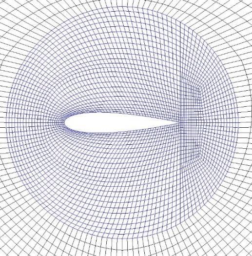
66 Figure 3.3 CFD meshes of the cycloidal blade system 55

67 3.1.2 Structural Design Figure 3.4 Designed cyclocopter The twin-rotor 110kg class UAV cyclocopter is designed as shown in Figure 3.4. It has two cycloidal main rotors and one propeller-type tail rotor. The tail rotor compensates anti-torque force and controls the pitching motion. The main rotors and the tail rotor rotate constant velocity and then its thrust force is controlled by changing the pitch angles. The rotational speeds of the main rotors and tail rotor are 420rpm and 5,320rpm, respectively. Some other small-scale cyclocopters are controlled by rotational speed of its main rotors but it is impossible for large-scale one because of the large inertia of its main rotors which are not able to control the thrust rapidly for maintaining stable hovering flight. The main rotors 56
68 rotate counterclockwise direction in Figure 3.4 and the tail rotor compensates for anti-torque and contributes to the lift force. Each main rotors consist of four blades and NACA0018 airfoils are used. The design specifications are listed in Table 3.2. Table 3.2 Design parameters of UAV cyclcopter Specifications Main rotor diameter Tail rotor diameter 2,000mm 574mm Number of main rotors 2 Number of blades per a main rotor 4 Blade Span length Blade chord length Airfoil Rotational speed of main rotors Rotational speed of a tail rotor 1,500mm 247mm NACA RPM 5,320RPM Max. Pitch angle 0~35º Length with rotors Height Width Total weight Chamber volume of engine 3,152mm 2,310mm 4,200mm 110kg 294cc 57
69 3.1.3 Power Transmission Cyclocopter rotors are actuated by a four-stroke single rotary engine. The rotary engine is based on the Wankel principle and has particular advantages for the cyclocopter. The engine is an Aixro XR50 model and made in Germany. The specifications of the XR50 are given in Table 3.3. The engine runs on regular gasoline and continuously outputs power of 29 hp. A rotary-type engine vibrates less than a reciprocating engine. The lack of vibration and compact size are merits for a prototype. Indeed, it is important to measure the vibrational characteristics of the cyclocopter aerodynamically and structurally. Table 3.3. Specifications of the engine Specifications Type Power Chamber Vol. Weight 4-stroke single rotor rotary engine 33kW at 8,750RPM 294cc 17kg Another advantage is a good starting ability. A conventional reciprocating engine has low torque at low speed and the torque rises as the rotational speed increases, whereas the torque curve of the XR50 is flat. The main rotors of the cyclocopter have larger structural inertia in comparison with the main rotor of a helicopter. Therefore, large torque of the XR50 at low speed is advantageous to the rotors starting up. Figure 3.5 provided by the engine manufacturer shows a flat torque curve from 4,000 to 8,000 rpm. When the engine runs at 58
70 6000 rpm, a reduction ratio of 14.3:1 is required for main-rotor rotation of 420 rpm. For this reduction mechanism, a timing belt-pulley and regular gears are applied. The engine is cooled with water to ensure sufficient cooling efficiency. Figure 3.6 shows the power train of the cyclocopter. The 12-V alternator charges a lead-acid battery and the battery then supplies electricity to the engine starting motor, actuators, gyro sensors and other electronic equipment. Figure 3.5 Engine performance data 59

71 Figure 3.6 Power train of cyclocopter The rotating shaft connected with a belt pulley device is an AL6063 metal pipe with diameter of 77 mm and thickness of 3.5 mm. Each cantilever-type power transmission shaft should support thrust of 50 kgf, which is a relatively low force. Therefore, static deflection is not a problem; however, the whirling of the shaft could be an issue because the weight is applied at the tip of the shaft. The whirling speed of the shaft is calculated according to [38] 4Ap l EI , (3.1) 3.67 EI 0 2 l A. (3.2) 60
72 The whirling speed of the shaft is thus calculated as 3633 rpm, which is higher than the designed rotating speed Blade Design The blades of the main rotor rotate in parallel to the rotating axis; thus, the bending moment is the main loading. Moreover, the centrifugal force is much stronger than the aerodynamic or gravity force. For instance, when the cyclocopter rotates the main rotors at 420 rpm, the blades experience forces of 197 G. Therefore, the structure of the blades should be strong enough to sustain the strong centrifugal force but lightweight to reduce the centrifugal force. The main structure of the blades consists of two C-shaped spars made from carbon composite material (Figure 3.7). Figure 3.8 shows the blade cross-section. Rectangular aluminum brackets were inserted in the blades and connected to the hub arms. In addition, an adhesive carbon composite patch was bonded to the skin of the surrounding bracket and reinforced to withstand centrifugal forces. The cyclocopter blades designed in a previous study were similarly 1 meter in length and had both ends connected with hub arms [17]. However, this configuration introduced very strong bending moments in the middle of the blade owing to the centrifugal forces generated in the high-speed rotation of rotors. To reduce bending moments acting on the blades, the supports of the blades are moved inward from the tip. Even though the total length of blades is extended to 1.5 m, the maximum bending stress is 68% less than that of the end-support type (Figure 3.9). 61

73 Figure 3.7 Internal structure of the blade Figure 3.8 Cross-sectional drawing of the main blade 62
74 Figure 3.9 Bending moment of the blades Efficiency Improvement The blade-tip vortex appears as the rotating speed increases and it attenuates the blade efficiency. End plates similar to winglets are attached to both ends of the blades to reduce drag. The end plate effect has been reported in NACA Technical Report 267 for a class of 63
75 conventional airplanes [39]. Although the flow pattern is a little different from that of the cycloidal blade system, applying the CD equation, the power saved was calculated in the report as h CL S b 2h CD 2C 2 F b 2h b b. (3.3) The endplate has height h of 125 mm and the blade span length, b, is 1500 mm. 2 C D CL 2 is obtained assuming is. Applying cycloidal blade systems with sinusoidal pitch angle variations and calculating for the two main rotors, the saving power is obtained as 1150 W (1.54 hp) Design of the Tail-rotor The torque of the main rotor should be known prior to the design of the tail rotor. First, the consumed power is estimated from previous experimental data and CFD results. Table 3.4 gives data related to the design of the tail rotor system. Figure 3.10 shows the contributions to the pitching moment by the related forces and the torque generated by the main rotors is equilibrated according to Mr Tr xr Tt xt. (3.4) 64
76 Table 3.4. Necessary data for design of the tail rotor Specifications Main rotor consume power (HP) 15 Main rotor rotation speed (RPM) 400 x r Main rotor position, (m) 0.05 x t Tail rotor position, (m) 2.25 Figure 3.10 Pitching moment equilibrium of the cyclocopter 65
77 The tail rotor needs to produce 9.86 kgf of thrust for the cyclocopter to remain in a stable equilibrium position according to Eq To control the pitching motion, additional thrust of the tail rotor should be considered Experiments Experiments were performed in two steps. Ground tests verified the CFD analysis results and theoretical model. Tethered flight tests were then conducted to verify the attitude control of the cyclocopter and the possibility of its stable hovering flight. Ground Tests The ground test bed is shown in Figure Five load cells were installed to measure forces. Three load cells were positioned in a triangular arrangement for the measurement of the lift force, rolling moment, and pitching moment. The two remaining cells were used to measure the yawing moment and forward backward force. Therefore, the test bed system was able to measure all force components generated by the cyclocopter. All load cells were of compression and tension type and rated at 100 kgf capacity. The force data were recorded using LABVIEW software. A compact DAQ with NI9237 modules was used. The rotational speed of the main rotor, engine temperature, and attitude data (roll, pitch, and yaw inputs and outputs) were recorded by the flight control computer installed on the cyclocopter. All measurements were made at intervals of 0.1 s. 66

78 Figure 3.11 Ground test Figure 3.12 compares the experimental and numerical analysis results of the main-rotor performance. It is found that the main rotors generate 130 kgf with maximum pitch angles of 23.5 degrees. The result coincides well with but is a little higher than the estimation made by CFD analysis and analytic simulation. This may be due to the ground effect in the tests. Figure 3.12 Ground test results 67
79 The lift direction of the cycloidal blade system is tilted by the rotating system. In achieving appropriate lift control, the exact propulsion direction is important because the flow direction is tilted as shown in the CFD results. Therefore, the flow tilt effect was investigated in the ground tests. Figure 3.13 shows the average tilt angles versus the maximum pitch angles from the fluctuating load cell data due to the dynamic effects. It is found that the tilt angles at the four maximum pitch angles are almost constant at 20. Figure 3.13 Flow tilt angles versus maximum pitch angle To compensate the flow tilt angles, the phase angle was tilted to 20 to produce vertical propulsion. The ground test was then repeated. The lift direction was almost vertical and the variation was less than 5, as shown in Figure
80 Figure 3.14 Flow tilt angle with a phase angle of 20 degrees Tethered flight-tests A tower crane was used to hang the cyclocopter. Figure 3.15 shows the cyclocopter tethered to the tower crane. For a safe tethered flight test, the hanging rope was properly tightened by a small counter weight on the other side of the crane so as not to accidently interfere with the rotors. The counter weight had an appropriate weight so as to tighten the rope while hardly assisting the lift of the cyclocopter. 69


81 Figure 3.15 Tethered flight test Figure 3.16 Block diagram of the flight control system A pilot transmits four set-point signals for the throttle, pitch, roll, and yaw. Thrust is changed by controlling the pitch angles of the blades, as for a conventional helicopter, whereas the rotational speed is kept constant. There are two ways of controlling the engine power and aerodynamic load to maintain constant rotational speed. In this model, the rotational speed 70
82 is controlled by the aerodynamic load because it allows a quick response. Figure 3.16 is a block diagram of the flight control system. A speed governor uses the collective pitch angle and controls the aerodynamic load to regulate the rotational speed of the rotor. According to the throttle signal, the engine carburetor opens and the rotor rotates more quickly until the desired rotational speed is reached and the collective pitch angle is then increased. The roll and yaw signals are in a closed-loop system embedded in a simple proportional-integral-derivative (PID) control algorithm. Furthermore, roll and yaw servos are operated in mixed mode to compensate for gyro effects of the rotor. A cyclocopter rotor rotates at high speed to produce enough thrust for flight. There are two gyroscopic effects: precession and nutation. These effects affect the lateral motion of the cyclocopter. A gyroscopic force due to the conservation of angular momentum is observed. The rotating rotor tends to resist changes to its orientation, which is also known as gyroscopic inertia. The main rotors of the cyclocopter are somewhat bigger than those of other rotorcraft. Thus, large gyroscopic inertia helps provide stability. Meanwhile, the gyroscopic effects mean that a yawing moment induces rolling. For the rotor rotating in the direction of positive pitch, a positive yawing moment generates the negative roll rate M r I xx x. (3.5) The induced roll rate (r) is proportional to the magnitude of the pitching moment (M) but I inversely proportional to the angular momentum ( xx x ). In other words, the faster the rotor rotates, the slower the precession occurs. Moreover, the roll and yaw motions oscillated with a similar period as shown in Figure This phenomenon might be due to nutation. 71
83 degree/sec For stable hovering flight, the PID gains were tuned and the compensation of these phenomena were applied to the control algorithm. Finally, the determined P, I, and D gains were, respectively, 0.245, 0.35, and 0.19 for both roll and yaw control. Figure 3.18 shows the hovering flight data with adjusted control gains. The cyclocopter was rotated about the yawing axis only when the test pilot manipulated a yawing input. It is seen that the roll and the yaw axes became completely decoupled. Therefore, the stability and maneuverability of the cyclocopter were ensured Time (sec) Rolling Rate Yawing Rate -20 Figure 3.17 Rolling and yawing motion (initial) 72
84 degree/sec Time (sec) Rolling Rate Yawing Rate -20 Figure 3.18 Rolling and yawing motion (stable) 3. 2 Cycloidal Vertical Axis Wind Turbine Typical VAWT designs include the drag type, Savonius type, lift type, and the Darrieus type [37]. The Darrieus type has higher efficiency caused by its use of the lift force induced by its rotating blades. However, the Darrieus type is difficult to self-start, and the Savonius type demonstrates low efficiency in rated rotation speed. To overcome these two challenges, a cycloidal vertical axis wind turbine (CWT) is proposed. CWTs start as the drag-type VAWT and become the lift type by changing the pattern of the pitch angles variation of their blades based on the operational rotation speed. 73
85 The aims of this chapter are follows. First, the optimal design of the rotor system in terms of airfoil shape, the number of blades, chord length, span length, rotor radius, rotation speed, solidity, and tip speed ratio will be investigated. To perform this optimization process, a CFD analysis and a response surface method are used. Second, two experiments are conducted to verify the performance and reliability of the designed CWT. Finally, the CWT with a flap device on the trailing edge of the blades to increase the efficiency is designed and analyzed by CFD; this system is the most efficient, as expected Design and Optimization CFD model for the CWT CFD analysis was performed to investigate the performance and characteristics of a cycloidal wind turbine. A commercially available program, STAR-CD (CD-adapco), was used for the CFD analysis [40]. To simulate the rotating and pitching motion of the blades, the moving mesh method is used in the boundary region, as shown in Figure 3.19d; an arbitrary sliding interface technique was used for the simulations. Figure 3.19 shows the mesh used in the analysis. The total number of cells was 47,104. Table 1 lists the parameters of the CFD analysis. The k ε/low Reynolds turbulence model is applied on the CFD model as the turbulence model. To converge on a solution in each of the cases, 1,600 time steps were computed; this corresponds to 8 revolutions. The cycloidal wind turbine consists of straight blades; therefore, a 2D analysis is suitable. The CFD analysis model presented here is similar to the authors previous research for a cycloidal water turbine [21]. For initial boundary conditions, the wind speed is 10 m/s and the rotor height is 2 m. Although many VAWTs function at their rated capacity at 12 or 14 m/s, the target wind speed 74
 Blade Domain, (b) Rotor Domain, (c) Outer Domain and (d) Boundary domain. In addition, the tip speed ratio (TSR) is considered at low values (i.e., TSR < 3).")
86 of the proposed VAWT is 10 m/s. This reduced target is a result the characteristics of urban wind (i.e., low speed and turbulent) described previously. Figure 3.19 CFD mesh (a) Blade Domain, (b) Rotor Domain, (c) Outer Domain and (d) Boundary domain. In addition, the tip speed ratio (TSR) is considered at low values (i.e., TSR < 3). A largescale, vertical axis wind turbine is generally most efficient with TSRs of between 5 and 7 [37]. The small-scale VAWT should have a lower TSR than the large-scale type because the 75
87 centrifugal force of the blade is inversely proportional to the rotor radius. For example, if a small-scale wind turbine has a 0.6-m radius with a TSR of 7 (at a wind speed of 12m/s), its blades should withstand 1,199 G of centrifugal acceleration, calculated by Eq. 3.6; these forces would be nearly impossible to withstand. Therefore, reduced TSRs are necessary to ensure the structural safety of small-scale VAWTs Vtip ( Vw TSR ) Centrifugal acceleration R (3.6) R R Optimization method Response surface method (RSM) refers to a mathematical and statistical technique which explores the relationships between experimental results and calculated variables [41, 42]. The objective is to maximize a power coefficient by changing several independent variables. With the RSM, a few calculations and experiments can derive an optimal result, especially when there are many and a wide range of variables for which the calculation process or the experiment requires a considerable amount of time. In this study, a second-order response surface, as described below, is assumed as Eq k k k k 2 0 j j jj j i, j i j j 1 j 1 j 1 i 1 (3.7) y x x x x The response surface is constructed with regression coefficients obtained from a data acquisition process, where 0, j, jj, ij,, and are partial regression coefficients of the intercept, linear, quadratic, interaction terms, and statistical error, respectively. The variables x x i and j are design variables. It is assumed that the design variables are continuous and controllable by the CFD analysis results with negligible error. The goal is to maximize the 76
88 wind turbine power coefficient, denoted by y, the response variable in Eq Using a least-square method to find optimized values, the reliability of the response surface can be 2 2 R adj verified by calculating an adjusted coefficient of multiple determination ( ). If the value ranges from 0.9 to 1, the optimization model is reliable. 2 SSE / ( n k 1) Radj 1 S / ( n 1) yy, 2 Radj is derived as Eq. 3.8: (3.8) R adj where SS E and Syy are defined as follows: SSE T T T y y X y, where n is the number of analyses. n T Syy yy yi / n i 1 2, (3.9) Results of the CFD analysis The power coefficient C p and the tip speed ratio TSR are defined by the following equations to represent the performance of the rotor. C p refers to the ratio between the power output of the rotor and wind energy. TSR is the ratio between the rotor blade tip speed and the wind speed. C p Poweroutput P Wind energy V A (3.10) Rotor BladeTipSpeed R TSR (3.11) WindVelocity V w w 77
89 Solidity is defined in Eq. 3.12; it is related to the number of blades, the chord length and the rotor radius. This variable represents the ratio between blade area and the rotor cylinder area. Nc (3.12) D Even when the chord length and the number of blades changes, the efficiency levels of wind turbine rotors are similar if the solidity remains fixed. Several cases, with four to six blades, with a fixed solidity of 0.21, were assessed in a CFD analysis. Figure 3.20 shows the results; the three graphs show nearly identical trends. In this study, a four-blade model is used because it is more structurally advantageous than other types. As the number of blades decrease, the blades should have longer chord lengths (Eq. 3.12) and a thicker structure. Two-blade or three-blade designs have longer chord lengths and larger blade-inertia than four to six blades designs but their flow distribution is relatively poor and many control loads are applied to the mechanical linkages. Figure 3.20 Comparison at different number of blades under the fixed solidity 78
90 When choosing the airfoil s design, it is important to consider the structural strength in addition to the efficiency. A thicker airfoil typically offers greater strength owing to its larger cross-sectional moment of inertia. The results of the airfoil design analysis conducted here are included in Table 2. The blade chord length, pitch angles, and TSR of the analysis conditions are 0.15 m, 10, and 2, respectively. NACA 6-series airfoils generally have greater C p values than the NACA 4-series airfoils; this is caused by NACA 6-series airfoils lower drag characteristics that result from the laminar air-flow that occurs over a substantial region of the airfoil. An additional advantage is that the efficiency of NACA 6-series airfoils is less sensitive to the rotor s rotation speed. The comparison of NACA 6-series and 4-digit airfoils was described by Migliore [43]. Results of the optimization The RSM was used for the optimization, and the design variables are blade chord length, blade pitch angle, and TSR. Based on the analysis conditions described previously, ranges for the blade chord length, pitch angles, and TSR are included in Table 3.5. Table 3.5. Range input for optimization Parameter Values Blade chord length ~ 0.18m Pitch angle 6 ~ 14 TSR 1 ~ 3 The construction of the response surface is important to secure reliability in some granular data. In this study, response surfaces are created with 60 of the CFD results and the central composite method (CCM) is used. The CCM is commonly used for second-order response 79
91 surfaces when they are applied in the design of an experiment. The dependent variable is determined with C p. Figure 3.21 is a graph of power coefficient and its relationship with pitch angle and the TSR. The constructed surface is a smooth quadratic form. Optimized by the least-square method, the results are shown in Table 3.6. The results of the RSM are verified by the adjusted 2 R adj coefficient of multiple determination ( ), calculated as Table 3.6. Optimization results of RSM Parameter Values Pitch angle TSR(Tip Speed Ratio) Chord length m Power Coefficient(Cp) The optimized pattern of the cycloidal pitch variation was a sinusoidal pattern and its neutral position was fixed at zero degrees. Considering the flow distribution, there is a different flow pattern between the upper and lower regions. Figure 3.22 shows the wind characteristics as a vector plot according to the CFD analysis. The operating conditions are 10 m/s wind speed, 10 of a pitch angle, and a TSR of 2.2. The energy of the wind at the upper rotor region is transformed to mechanical energy; the wind speed at the lower region decreases below the original inlet wind speed. Therefore, a meaningful CFD analysis needs to vary the neutral position. The angle of this position is known as the initial pitch angle. Figure 3.23 illustrates a graph that plots C p against initial pitch angle. Other conditions are fixed at optimum values (i.e., 10 of a pitch angle, 2.2 of TSR, and 0.15 m chord length). In conclusion, according to 80
. Figure 3.")
92 the observed results, the maximum efficiency is 41%, at an initial pitch angle of 3 ( 7 to 13 of cyclic pitch variation). Figure 3.21 Response surface of power coefficient 81

93 Figure 3.22 Vector plot of the flow around rotor blades Figure 3.23 Power coefficient versus initial pitch angles 82
94 3.2.2 Experiments For experimental purposes, a 600 W class cycloidal wind turbine was developed. The design variables are shown in Table 3.6 and the experimental model is shown in Figure The rotor radius is 0.6 m and the control linkages are connected to the leading edge of the blades. The control rods are operated and located inside the hub arms to reduce drag. Furthermore, the roots of these control arms are connected to one point that is located in an off-center location. The magnitude of this eccentricity is the maximum blade pitch angle of the cyclic variation. When the wind direction changes, the phase angle (i.e., the position of the maximum pitch angle) will adjust to the wind s direction by means of an active control technique. The wind direction is measured with an anemoscope; its signal drives a step motor (shown in Figure 3.24c) to adjust the phase angle. Control power is consumed only when the wind direction changes and is expected to be very small. This reduced consumption can be attributed to fact that the vertical-axis wind turbine simply changes the phase angle, rather than turning the whole device. The alternator connected under the hub arms is an SYG-245- B model (Seoyoung Tech Co., Ltd., Gumi-City, Kyungbuk, Korea) that uses an axial-flux permanent magnet as shown in Figure 3.24a. Its rated output is 600 W at 300 RPM and it requires a three-phase electrical connection. The blade and hub arm section are NACA type. The blades of the vertical-axis wind turbine undergo substantial bending stresses and are therefore a weak structural point. To reduce the bending stress, a light weight and a large bending moment of inertia are required. In this study, the blade material is an aluminum alloy (AL6061). Although composite materials are lighter and stronger, these materials are difficult to manufacture and demonstrate non-uniform properties depending on the direction of applied forces. Therefore, 83


95 the blades were manufactured by a hot extrusion process to reduce costs and to achieve uniformity. It is feasible to reduce the hub arm drag because the NACA 6-series airfoil is a low-drag airfoil. Figure 3.24 Cycloidal wind turbine (a) Whole view (b) Top view and (c) Detail view of the control part Initial experiments were attempted in a wind tunnel; however, no satisfactory results were obtained. The wind tunnel facility is located at Chonbuk National University in Korea. It is 5 m wide, 2.5 m high, and 20 m long. The swept area of the experimental model presented here is 2.4 m 2. The increased blockage effect, caused by operating a relatively large model in the wind tunnel, made test data less reliable by interference with wind tunnel wall. 84
96 Although the blockage rate is 19% in the study, the blockage effect was serious. As wind speeds increase, vibrations occurred in the wind turbine rotor. These vibrations did not occur in the other tests. For this reason, the authors concluded that the model s interaction with the wind tunnel was the cause of the vibrations. Experiments were performed in two steps. The wind turbine was calibrated in a constant wind speed test and then a field test was performed. The constant wind speed test, with the relative wind speed controlled by the carrier truck s speed, is dynamically equivalent to the wind tunnel test. Using this approach, there is no need to consider blockage corrections. In the wind tunnel experiments, the results obtained are greater than the actual data owing to the previously described blockage effect. If the blockage ratio, defined as the rotor swept area divided by the wind tunnel cross-sectional area, exceeds 10%, blockage correction must be performed to reduce errors [44]. Constant wind speed test A constant wind speed test using a truck to carry the experimental rig is conducted on an open and straight road. Tests were only performed on days with low wind speeds. To control the wind speed, an anemometer was installed in front of the wind turbine and its display was positioned on the truck s dashboard, where the driver can see it. The wind turbine test system measured the wind s speed and direction, and then adjusted the pitch angle pattern of the CWT to the design point, in real time. The test strut was mounted on the cargo bed of a 1.5- ton pick-up truck. The test jig is elevated above the roof height to avoid air flow disturbances caused by the truck cabin. Figure 3.25 and 3.26 show the constant wind speed test procedure and the control mechanism of the cycloidal wind turbine, respectively. All of the measuring data are recorded using National Instruments, LabVIEW devices. 85


97 Figure 3.25 Procedure of the constant wind speed test Figure 3.26 Control system of the cycloidal wind turbine 86

98 Figure 3.27 Power measuring method of the constant wind speed test Figure 3.27 illustrates the measurement method for both the mechanical and electrical output. For mechanical power measurement, a torque sensor and a hall sensor have been installed. The NI9237 terminal block is used to collect the torque data. Additionally, the NI9239 terminal block is used to measure the RPM, wind speed, and wind direction. A laptop computer recorded all data and displayed the data and graphs in real time. Because the generated electric energy was not stored, an electric load device was required. The rotational speed of the wind turbine rotor can be controlled by this electric load. An electronic load device can control the load electronically and display the electrical resistance value (ohms), voltage (volts), and current (amps). The equipment used in this experiment is the Programmable DC electronic load device manufactured by Chroma Co., Ltd; it can 87
99 consume a maximum of 2.6kW of electric energy. The mechanical power output could be measured by torque, and RPM; electrical power was measured by the DC electronic load device. Figure 3.28 the C p result according to TSR with various pitch angles Figure 3.28 shows the result of the comparisons. The difference between the observed results was attributed to the drag of the hub-arms and mechanical losses. The experimental results align with the CFD analysis. The C p increases with TSR, attains the highest value at the design point (TSR = ), and then decreases with further increase in TSR. Furthermore, the optimal value of TSR decreased as the maximum pitch angles increased. The highest C p value (0.378) was obtained at a 10 pitch angle. 88
100 Figure 3.29 Cp results of the constant wind speed test To determine the optimal electric resistance value, a C p versus ohms characterization was completed, as shown in Figure 3.29; the optimal value is approximately ohms. If the resistance is too high, the number of revolutions will be reduced and the output power will decrease. Contrarily, if the resistance is too low, the electric current will be reduced and the output power will decrease. Therefore, the optimal electric resistance value obtained from the experimental results was applied to a universal wind turbine controller in a field test; this is described in the next Section. 89
101 Figure 3.30 The experimental results compared with CFD result Figure 3.30 shows the experimental results compared to the CFD results. The experimental data are the average values taken over a 10-s period after full stabilization has occurred. The mechanical power graph was obtained by taking the product of the torque sensor value and the RPM. Similarly, the electrical power graph was obtained by taking the product of the voltage and the current, as measured by the electronic load device. The CFD values are higher than the experimental values; this result can be explained by the fact that the CFD approach was two-dimensional and neglected the drag of the hub arms and other factors. Considering these errors, the mechanical power was approximately 10% lower than the CFD 90

102 results. The electrical power graph results were lower than the measured mechanical values; this difference is mostly caused by the electrical losses of the alternator and rectifier. Field tests Field tests were performed at the experimental site of the Korea Institute of Energy Research in Jeju Island. This site is commonly used for the certification of small wind turbines. The equipped measurement devices are calibrated regularly and are highly reliable. Figure 3.31 and 3.32 show the installation of the field test and the power measurement setup, respectively. The objective of the field test is to verify the overall system, including the battery charger device. The controller is a WWS06A-24-R-L model (Hefei Win Power Co., Ltd.). The controller s internal resister value is set to 1.75 ohms; this value was obtained from the constant wind speed tests. The three-phase voltage and current, two-phase voltage and current, and wind speed are recorded. Figure 3.31 Field test of the wind turbine 91


103 Figure 3.32 Power measuring method of the field test Figure 3.33 Experimental result of the field test 92
104 The total field test duration is 2 months; the results are shown in Figure All of the data are measured every second, averaged every minute, and then recorded to one point. The wind conditions experienced during a field test are not as predictable as those experienced in a wind tunnel or during a constant wind speed test. The object of the field test is to quantify how much electric power is generated by the proposed system during typical operations, and to investigate the system s reliability. The CWT can rapidly cope with changing wind directions through the electronic control algorithm. Because the rotor s inertia is relatively large compared with an HAWT, the rotational speed of the rotor gradually changes with variations in wind speed. According to the wind speed record on a windy day, wind speeds oscillate between 6 and 10 m/s (Figure 3.34). Figure 3.34 Wind speed records of the field test 2 The rotor inertia is 27.6kg m and the acceleration time is 33 s to achieve optimal rotational speed after the wind speed increases from 6 to 10 m/s. When a strong gust of wind occurs, the wind speed increases considerably but the additional electricity generated is low. For this reason, the data points obtained during the field test are widely spread and lower than the 93

105 results obtained by the CFD analysis. Furthermore, the electric resistance value of the controller is fixed as 1.75 ohms according to functional limitations, although the optimum electric resistance value is changed by TSR. Considering these field test conditions, the test results were reasonably accurate and verified the system s performance. During the 2 months of the field test period, the proposed CWT demonstrated strong reliability and durability. As a result of these test outcomes, a cycloidal vertical-axis wind turbine system with a street light and solar panels was installed in the aeronautical center of the Korean Aerospace Research Institute, Goheung, Korea. Figure 3.35a shows the cycloidal vertical-axis wind turbine system powering the attached street light. Figure 3.35b shows the batteries, controller, and the electric circuit switch that are located inside the control box. Figure 3.35 The cycloidal vertical axis wind turbine system with street light (a) whole view and (b) control box 94
106 In future works, if numerous light-emitting devices are mounted on the blades, the cycloidal wind turbine can be used as a display device. Our team was granted a patent for a displayable wind turbine [45]. 95

107 4. CONCLUSIONS This study described the design and development of a 110-kg twin-rotor UAV cyclocopter and a high-efficiency, cycloidal, vertical axis wind turbine system. To estimate its performance, a novel theoretical aerodynamic model was proposed as the analytical model and two-dimensional CFD analysis was conducted. Cyclocopters are generally classified as twin-rotor and quad-rotor types. Although the control algorithm of the twin-rotor cyclocopter is more complex, the twin-rotor cyclocopter has the advantages of a compact structure, flow stream interference, and forward flight. Therefore, a twin-rotor cyclocopter was developed for the experimental model. The analytical and numerical (CFD analysis) results were verified by ground tests. When applying an empirical factor of 1.15, the theoretical result is almost same as the CFD analysis result. Although the experimental results are a little higher because of the ground effect, these results are reliable. Figure 4.1 Stable hover flight of the cyclocopter 96
108 The twin-rotor cyclocopter demonstrated stable hovering flight under a tethered condition successfully (Figure 4.1). The control algorithm of the twin-rotor type could decouple the roll and yaw motions and compensated for gyro precession and nutation. Moreover, the PID gains of the flight control computer were tuned to optimal values during tethered flight tests. Stable hovering flight could be demonstrated without strings; however, it was not performed owing to safety reasons, especially those relating to take-off and landing. The payload of the cyclocopter was 2 kg, which is lower than that expected for a practical vehicle owing to a lack of engine power. In future work, the cyclocopter will be equipped with a more powerful engine so that it can maneuver in free flight outdoors. The proposed CWT was designed to be highly efficient, allow control of blade pitch angles, and allow self-starting. With these objectives in mind, the CWT has four straight blades that turn in a sinusoidal pattern based on the pitch angle. To conduct a CFD analysis, a twodimensional moving mesh model was developed and deployed based on the arbitrary sliding interface technique. The CFD airfoil analyses allowed the optimal airfoil to be identified. Compared with the NACA 4-series airfoils, the NACA 6-series airfoils are more efficient and less influenced by rotational speed. The NACA was selected for the proposed CWT. The optimal pitch angle, TSR, and chord length were determined using a response surface method. To reduce the centrifugal force, the lowest TSR value was chosen. To improve the safety of the CWT system, the blades were tightly secured to the body of the CWT. By adjusting the initial pitch angle (a neutral position of the sinusoidal variation), the optimized CWT system showed a higher power coefficient. To verify the experimental results, the proposed CWT was manufactured and tested. A large number of blades and hub-arms were required because many CWTs were needed for the extensive testing campaign. The blades were manufactured via a hot extrusion process. Two 97
109 types of experiment were performed. The results of the constant wind speed test were shown to align with the results obtained with the CFD analyses. Field tests were conducted to compare the proposed CWT system s performance in natural wind conditions with the results predicted during the design phase. The efficiency of the CWT system was further improved by attaching the flap devices to the trailing edge of the blades. The CFD analysis showed notable improvements (approximately 18%) in the power coefficient for the flap devices. Additionally, the flap devices were operated by mechanical linkages and consumed very little operating power. We found that the proposed CWT is not only efficient in urban environments but also economical owing to the possibility of mass producing low-cost straight blades and hub arms. 98
110 REFERENCES 1. Eastman, F. S. The Full-Feathering Cyclogiro: University of Washington, Aeronautical Laboratory, Eastman, F. S., Burkheimer, G., and Cottar, W. Wind Tunnel Tests on a High Pitch Cyclogyro: University of Washington, Aeronautical Laboratory, Kirsten, F. K. "Cycloidal propulsion applied to aircraft," Transactions of the American society of Mechanical Engineers Vol. 50, No. 12, 1928, pp Kirsten, F. K. Cycloidal propulsion in air: Univ., Wheatley, J. B. "Simplified aerodynamic analysis of the cyclogiro rotating wing system," Wheatley, J. B., and Windler, R. "Wind-tunnel tests of a cyclogiro rotor," Foshag, W. F., and Boehler, G. D. "Review and Preliminary Evaluation of Lifting Horizontal-Axis Rotating-Wing Aeronautical Systems (HARWAS)." DTIC Document, Yun, C. Y. "A new vertical take-off and landing aircraft with cycloidal blades system: cyclocopter." Ph. D thesis, Seoul National University, Yun, Y. H. "An experimental study on cycloidal propulsion system." Master thesis, Seoul National University, Park, I. K. "Optimized rotor design of UAV cyclocopter with cycloidal blades system." Master Thesis, Seoul National University, Jung, J. S. "An Experimental Study of UAV Cyclocopter with Cycloidal Blades System." Master Thesis, Seoul National University, Lee, H. Y. "An Experimental Study of VTOL UAV Cyclocopter for Performance Improvement." Master Thesis, Seoul National University, Yun, C. Y., Park, I. K., Lee, H. Y., Jung, J. S., Hwang, I. S., and Kim, S. J. "Design of a New Unmanned Aerial Vehicle Cyclocopter," Journal of the American Helicopter Society Vol. 52, No. 1, 2007, pp
111 14. Hwang, I. "Numerical and Experimental Study on Design and Development of Quadrotor Cyclocopter." PhD Thesis, Seoul National University, Min, S. Y. "System Improvement and Experimental Study for the Flight of Quadrotor Cyclocopter." Ph.D thesis, Seoul National University, Hwang, I. S., Min, S. Y., Lee, C. H., and Kim, S. J. "Structural Design and Analysis of Elliptic Cyclocopter Rotor Blades." KSCM, Hwang, I. S., Hwang, C. S., Min, S. Y., Jeong, I. O., Lee, C. H., Lee, Y. H., and Kim, S. J. "Design and testing of VTOL UAV cyclocopter with 4 rotors," ANNUAL FORUM PROCEEDINGS-AMERICAN HELICOPTER SOCIETY. Vol. 62, AMERICAN HELICOPTER SOCIETY, INC, 2006, p Min, S. Y., Lee, C. H., Seung, M. H., Kim, Y. S., Hur, C. M., and Kim, S. J. "Experimental Study of a Quadrotor Cyclocopter," Journal of the American Helicopter Society Vol. 60, No. 3, 2015, pp Hwang, I. S., Lee, Y. H., and Kim, S. J. "Aerodynamic analysis and control mechanism design of cycloidal wind turbine adopting active control of blade motion," International Journal of Aeronautical and Space Sciences Vol. 8, No. 2, 2007, pp Lee, Y. H. "Performance Analysis and Design of Vertical Axis Hydro Turbine using Cycloidal Blade System." Master Thesis, Seoul National University, Hwang, I. S., Lee, Y. H., and Kim, S. J. "Optimization of cycloidal water turbine and the performance improvement by individual blade control," Applied Energy Vol. 86, No. 9, 2009, pp Boschma, J. H. "Cycloidal propulsion for UAV VTOL applications." DTIC Document, Gibbens, R. P., Boschma, J. H., and Sullivan, C. "Construction and testing of a new aircraft cycloidal propeller," 13th AIAA lighter-than-air systems technology conference. 1999, pp Boschma, J. H. "Modern aviation applications for cycloidal propulsion," AIAA, Aircraft, Technology Integration and Operations Forum, Los Angeles, CA McNabb, M. L. "Development of a cycloidal propulsion computer model and comparison with experiment." Mississippi State University,
112 26. Iosilevskii, G., and Levy, Y. "Experimental and numerical study of cyclogiro aerodynamics," AIAA journal Vol. 44, No. 12, 2006, pp Tanaka, K., Suzuki, R., Emaru, T., Higashi, Y., and Wang, H. O. "Development of a cyclogyro-based flying robot with variable attack angle mechanisms," Mechatronics, IEEE/ASME Transactions on Vol. 12, No. 5, 2007, pp Yu, H., Bin, L. K., and Rong, H. W. "The research on the performance of cyclogyro," AIAA 6th Aviation Technology, Integration and Operations Conference Proceedings, AIAA Paper. Vol. 7704, Boirum, C. G., and Post, S. L. "Review of historic and modern cyclogyro design," _ 45th AIAA/ASME/SAE/ASEE Joint Propulsion Conference and Exhibit _ Benedict, M., Chopra, I., Ramasamy, M., and Leishman, J. "Experimental investigation of the cycloidal-rotor concept for a hovering micro air vehicle," ANNUAL FORUM PROCEEDINGS-AMERICAN HELICOPTER SOCIETY. Vol. 64, AMERICAN HELICOPTER SOCIETY, INC, 2008, p Benedict, M., Gupta, R., and Chopra, I. "Design, development and flight testing of a twin-rotor cyclocopter micro air vehicle," Proceedings of the 67th Annual National Forum of the American Helicopter Society. Curran Associates, Inc. Virginia Beach, VA, 2011, pp Benedict, M., Jarugumilli, T., Lakshminarayan, V., and Chopra, I. "Experimental and computational studies to understand the role of flow curvature effects on the aerodynamic performance of a MAV-scale cycloidal rotor in forward flight," Proceedings of the 53rd AIAA/ASME/ASCE/AHS/ASC structures, structural dynamics, and materials conference, Honolulu, Hawaii Benedict, M., Ramasamy, M., and Chopra, I. "Improving the aerodynamic performance of micro-air-vehicle-scale cycloidal rotor: an experimental approach," Journal of Aircraft Vol. 47, No. 4, 2010, pp Benedict, M., Ramasamy, M., Chopra, I., and Leishman, J. G. "Performance of a cycloidal rotor concept for micro air vehicle applications," Journal of the American Helicopter Society Vol. 55, No. 2, 2010, pp Darrieus, G. "Turbine having its rotating shaft transverse to the flow of the current." U.S. Patents , December
113 36. Richards, B. "Initial Operation of Project Eole 4MW Vertical-Axis Wind Turbine Generator," Proceedings of the Windpower. Vol. 87, Paraschivoiu, I. Wind turbine design: with emphasis on Darrieus concept: Presses inter Polytechnique, Newland, D. "Whirling of a cantilever elastic shaft subjected to external pressure," Journal of Mechanical Engineering Science Vol. 14, No. 1, 1972, pp Hemke, P. E. Drag of wings with end plates: National Advisory Committee for Aeronautics Report No.267, CD-adapco group. "Star-CD Version 3.20 User Guide," Jo, M. K. "Structural Optimization using Monte Carlo Simulation and RSM." Vol. Master' thesis, Seoul National University, Seoul, Myers, R. H. Classical and modern regression with applications: Duxbury Press Belmont, CA, Migliore, P. "Comparison of NACA 6-series and 4-digit airfoils for Darrieus wind turbines," Journal of Energy Vol. 7, No. 4, 1983, pp Chen, T., and Liou, L. "Blockage corrections in wind tunnel tests of small horizontalaxis wind turbines," Experimental Thermal and Fluid Science Vol. 35, No. 3, 2011, pp Kim, S. J. "Displayable wind turbine." Vol , , U.S.,

114 APPENDIX A. MANUFACTURING AND DRAWING OF THE CYCLOCOPTER For the main frame and power transmission of the 110kg class twin-rotor cyclocopter, a pesticide spray helicopter was used; its model name is REMO-H2 (SUNGWOO Eng. Co., Ltd., Cheongju-City, Chungbuk, Korea). Only the main rotors of the cyclocopter and control system were made and installed. This way saved a lot of time and effort. Figure A. 1 REMO-H 2 (helicopter) Blade manufacturing The blades of the cyclocopter consisted of carbon composite spars, glass-balsa wood composite skin and balsa ribs. Figure A. 2 shows blade molds. The airfoil type of blades was NACA0018 and its chord length is 247mm. At first, a master model blade was made by using Styrofoam and then applied Gelcoat. Blade molds were manufactured when Gelcoat sufficiently cured and removed from the master model blade. 103


115 Figure A. 4 shows the manufacturing process of blade spar used in the blades. Two U-shaped spars were placed in each of the blades and support most of loading, especially the centrifugal force by the rotor rotation. Figure A. 2 Blade molds Figure A. 3 Spar molds 104

116 Figure A. 4 Manufacturing process of the blade spar 105

117 Balsa ribs and carbon spars were bonded to the skin by epoxy resin as shown in Figure A. 5. The carbon spars were located by using jig, which is the yellow part in Figure A. 5, because of accuracy and unity of the each blades. Figure A. 5 Assembly of rib, spar and skin 106

118 Figure A. 6 main blades of the cyclocopter 107

119 Hub-arm manufacturing Eight hub-arms were used for one rotor assembly. Figure A. 7 shows manufacturing process of the hub-arms. A carbon-glass-epoxy resin hand-layup method were used for manufacturing. Figure A. 7 Manufacturing process of the hub-arms 108

 109")
120 In the root and tip parts of the hub-arms, additional carbon fibers were applied for reinforcement as shown in Figure A. 8 and A. 9. Figure A. 8 Root of the hub-arms (inside) Figure A. 9 Tip of the hub-arms (inside) 109
121 Drawing of the cyclocopter Figure A. 10 Isometric drawing of the cyclocopter 110
122 Figure A. 11 Top view of the cyclocopter 111
123 Figure A. 12 Side view of the cyclocopter 112
124 Figure A. 13 Front view of the cyclocopter 113
125 APPENDIX B. MANUFACTURING OF THE CYCLOIDAL WIND TURBINE The blades and hub-arms were manufactured via an aluminum hot extrusion process. A hot extrusion process is a process used to create the products of a fixed cross-sectional profile. The two main advantages of this process over other manufacturing processes are its ability to create very complex cross-sections and low-priced manufacturing costs. It also forms parts with an excellent surface finish. Figure B. 1 shows the cross-sectional drawing of the blade and hub-arm. Figure B. 1 Cross-sectional drawing of the blade and hub-arm 114


126 The hub-arms and blades were additionally machined for accuracy cutting and boring bolt holes by CNC milling machine as shown in Figure B. 2. Figure B. 2 Manufacturing root part of the hub-arm using CNC machine Figure B. 3 The blade in connection part of the control linkage 115


127 Figure B. 4 The picture and drawing of the hub-arm Figure B. 5 Surface machining of the alternator 116

128 The hub-arms were assembled on the surface of the alternator directly. Thus, the surface of the alternator was machined by a lathe machine (Figure B. 5). Figure B. 6 shows control system of the cycloidal wind turbine. For control pitch angle pattern, a step motor and absolute rotary encoder were used. The control rods were located inside the hub-arms to reduce the aerodynamic drag force. Figure B. 6 Control system of the cycloidal wind turbine 117

129 Figure B. 7 Cycloidal wind turbine 118
DESIGN AND EXPERIMENT OF TWO-ROTORED UAV CYCLOCOPTER
 Choong Hee Lee*, Seung Yong Min**, Jong Won Lee**, Seung Jo Kim* *Seoul National University, **Korea Aerospace Research Institute Keywords: Cyclocopter, Cyclogyro, UAV, VTOL Abstract This paper describes
THE INVESTIGATION OF CYCLOGYRO DESIGN AND THE PERFORMANCE
 25 TH INTERNATIONAL CONGRESS OF THE AERONAUTICAL SCIENCES THE INVESTIGATION OF CYCLOGYRO DESIGN AND THE PERFORMANCE Hu Yu, Lim Kah Bin, Tay Wee Beng Department of Mechanical Engineering, National University
STRUCTURAL DESIGN AND ANALYSIS OF ELLIPTIC CYCLOCOPTER ROTOR BLADES
 16 TH INTERNATIONAL CONFERENCE ON COMPOSITE MATERIALS STRUCTURAL DESIGN AND ANALYSIS OF ELLIPTIC CYCLOCOPTER ROTOR BLADES In Seong Hwang 1, Seung Yong Min 1, Choong Hee Lee 1, Yun Han Lee 1 and Seung Jo
EFFECT OF SURFACE ROUGHNESS ON PERFORMANCE OF WIND TURBINE
 Chapter-5 EFFECT OF SURFACE ROUGHNESS ON PERFORMANCE OF WIND TURBINE 5.1 Introduction The development of modern airfoil, for their use in wind turbines was initiated in the year 1980. The requirements
International Journal of Scientific & Engineering Research, Volume 4, Issue 7, July ISSN BY B.MADHAN KUMAR
 International Journal of Scientific & Engineering Research, Volume 4, Issue 7, July-2013 485 FLYING HOVER BIKE, A SMALL AERIAL VEHICLE FOR COMMERCIAL OR. SURVEYING PURPOSES BY B.MADHAN KUMAR Department
CFD on Cavitation around Marine Propellers with Energy-Saving Devices
 63 CFD on Cavitation around Marine Propellers with Energy-Saving Devices CHIHARU KAWAKITA *1 REIKO TAKASHIMA *2 KEI SATO *2 Mitsubishi Heavy Industries, Ltd. (MHI) has developed energy-saving devices that
Robot Dynamics Rotary Wing UAS: Introduction, Mechanical Design and Aerodynamics
 Robot Dynamics Rotary Wing UAS: Introduction, Mechanical Design and Aerodynamics 151-0851-00 V Marco Hutter, Michael Blösch, Roland Siegwart, Konrad Rudin and Thomas Stastny Robot Dynamics: Rotary Wing
A CFD-Based Approach to Coaxial Rotor Hover Performance Using Actuator Disks. Jonathan Chiew
 A CFD-Based Approach to Coaxial Rotor Hover Performance Using Actuator Disks Jonathan Chiew AE4699 - Spring 007 Dr. Lakshmi Sankar Georgia Institute of Technology Table of Contents Table of Contents Introduction
Electric Drive - Magnetic Suspension Rotorcraft Technologies
 Electric Drive - Suspension Rotorcraft Technologies William Nunnally Chief Scientist SunLase, Inc. Sapulpa, OK 74066-6032 wcn.sunlase@gmail.com ABSTRACT The recent advances in electromagnetic technologies
Guide Vanes for Darrieus Water Turbine in Tidal Current
 International Conference on Renewable Energies and Power Quality (ICREPQ 13) Bilbao (Spain), 20 th to 22 th March, 2013 Renewable Energy and Power Quality Journal (RE&PQJ) ISSN 2172-038 X, No.11, March
Effect of Stator Shape on the Performance of Torque Converter
 16 th International Conference on AEROSPACE SCIENCES & AVIATION TECHNOLOGY, ASAT - 16 May 26-28, 2015, E-Mail: asat@mtc.edu.eg Military Technical College, Kobry Elkobbah, Cairo, Egypt Tel : +(202) 24025292
Lecture 5 : Static Lateral Stability and Control. or how not to move like a crab. G. Leng, Flight Dynamics, Stability & Control
 Lecture 5 : Static Lateral Stability and Control or how not to move like a crab 1.0 Lateral static stability Lateral static stability refers to the ability of the aircraft to generate a yawing moment to
High aspect ratio for high endurance. Mechanical simplicity. Low empty weight. STOVL or STOL capability. And for the propulsion system:
 Idealized tilt-thrust (U) All of the UAV options that we've been able to analyze suffer from some deficiency. A diesel, fixed-wing UAV could possibly satisfy the range and endurance objectives, but integration
Autonomous Mobile Robot Design
 Autonomous Mobile Robot Design Topic: Propulsion Systems for Robotics Dr. Kostas Alexis (CSE) Propulsion Systems for Robotics How do I move? Understanding propulsion systems is about knowing how a mobile
Design Considerations for Stability: Civil Aircraft
 Design Considerations for Stability: Civil Aircraft From the discussion on aircraft behavior in a small disturbance, it is clear that both aircraft geometry and mass distribution are important in the design
Aerodynamic Characteristics of Sedan with the Rolling Road Ground Effect Simulation System
 Vehicle Engineering (VE) Volume 2, 2014 www.seipub.org/ve Aerodynamic Characteristics of Sedan with the Rolling Road Ground Effect Simulation System Yingchao Zhang 1, Linlin Ren 1, Kecheng Pan 2, Zhe Zhang*
Reduction of Self Induced Vibration in Rotary Stirling Cycle Coolers
 Reduction of Self Induced Vibration in Rotary Stirling Cycle Coolers U. Bin-Nun FLIR Systems Inc. Boston, MA 01862 ABSTRACT Cryocooler self induced vibration is a major consideration in the design of IR
Preface. Acknowledgments. List of Tables. Nomenclature: organizations. Nomenclature: acronyms. Nomenclature: main symbols. Nomenclature: Greek symbols
 Contents Preface Acknowledgments List of Tables Nomenclature: organizations Nomenclature: acronyms Nomenclature: main symbols Nomenclature: Greek symbols Nomenclature: subscripts/superscripts Supplements
DESIGN AND DEVELOPMENT OF A MICRO AIR VEHICLE (µav) CONCEPT: PROJECT BIDULE
 CONCEPT: PROJECT BIDULE") DESIGN AND DEVELOPMENT OF A MICRO AIR VEHIE (µav) CONCEPT: PROJECT BIDULE Mr T. Spoerry, Dr K.C. Wong School of Aerospace, Mechanical and Mechatronic Engineering University of Sydney NSW 6 Abstract This
DESIGN AND DEVELOPMENT OF A MICRO AIR VEHIE (µav) CONCEPT: PROJECT BIDULE Mr T. Spoerry, Dr K.C. Wong School of Aerospace, Mechanical and Mechatronic Engineering University of Sydney NSW 6 Abstract This
Design and Test of Transonic Compressor Rotor with Tandem Cascade
 Proceedings of the International Gas Turbine Congress 2003 Tokyo November 2-7, 2003 IGTC2003Tokyo TS-108 Design and Test of Transonic Compressor Rotor with Tandem Cascade Yusuke SAKAI, Akinori MATSUOKA,
Special edition paper
 Efforts for Greater Ride Comfort Koji Asano* Yasushi Kajitani* Aiming to improve of ride comfort, we have worked to overcome issues increasing Shinkansen speed including control of vertical and lateral
1.1 REMOTELY PILOTED AIRCRAFTS
 CHAPTER 1 1.1 REMOTELY PILOTED AIRCRAFTS Remotely Piloted aircrafts or RC Aircrafts are small model radiocontrolled airplanes that fly using electric motor, gas powered IC engines or small model jet engines.
Prop effects (Why we need right thrust) Torque reaction Spiraling Slipstream Asymmetric Loading of the Propeller (P-Factor) Gyroscopic Precession
 Torque reaction Spiraling Slipstream Asymmetric Loading of the Propeller (P-Factor) Gyroscopic Precession") Prop effects (Why we need right thrust) Torque reaction Spiraling Slipstream Asymmetric Loading of the Propeller (P-Factor) Gyroscopic Precession Propeller torque effect Influence of engine torque on aircraft
Prop effects (Why we need right thrust) Torque reaction Spiraling Slipstream Asymmetric Loading of the Propeller (P-Factor) Gyroscopic Precession Propeller torque effect Influence of engine torque on aircraft
International Journal of Scientific & Engineering Research, Volume 5, Issue 7, July-2014 ISSN
 ISSN 9-5518 970 College of Engineering Trivandrum Department of Mechanical Engineering arundanam@gmail.com, arjunjk91@gmail.com Abstract This paper investigates the performance of a shock tube with air
Drones Demystified! Topic: Propulsion Systems
 Drones Demystified! K. Alexis, C. Papachristos, Autonomous Robots Lab, University of Nevada, Reno A. Tzes, Autonomous Robots & Intelligent Systems Lab, NYU Abu Dhabi Drones Demystified! Topic: Propulsion
Figure 1: Forces Are Equal When Both Their Magnitudes and Directions Are the Same
 Moving and Maneuvering 1 Cornerstone Electronics Technology and Robotics III (Notes primarily from Underwater Robotics Science Design and Fabrication, an excellent book for the design, fabrication, and
LEAD SCREWS 101 A BASIC GUIDE TO IMPLEMENTING A LEAD SCREW ASSEMBLY FOR ANY DESIGN
 LEAD SCREWS 101 A BASIC GUIDE TO IMPLEMENTING A LEAD SCREW ASSEMBLY FOR ANY DESIGN Released by: Keith Knight Kerk Products Division Haydon Kerk Motion Solutions Lead Screws 101: A Basic Guide to Implementing
Design of Helical Gear and Analysis on Gear Tooth
 Design of Helical Gear and Analysis on Gear Tooth Indrale Ratnadeep Ramesh Rao M.Tech Student ABSTRACT Gears are mainly used to transmit the power in mechanical power transmission systems. These gears
CHAPTER THREE DC MOTOR OVERVIEW AND MATHEMATICAL MODEL
 CHAPTER THREE DC MOTOR OVERVIEW AND MATHEMATICAL MODEL 3.1 Introduction Almost every mechanical movement that we see around us is accomplished by an electric motor. Electric machines are a means of converting
Powertrain Design for Hand- Launchable Long Endurance Unmanned Aerial Vehicles
 Powertrain Design for Hand- Launchable Long Endurance Unmanned Aerial Vehicles Stuart Boland Derek Keen 1 Justin Nelson Brian Taylor Nick Wagner Dr. Thomas Bradley 47 th AIAA/ASME/SAE/ASEE JPC Outline
R10 Set No: 1 ''' ' '' '' '' Code No: R31033
 R10 Set No: 1 III B.Tech. I Semester Regular and Supplementary Examinations, December - 2013 DYNAMICS OF MACHINERY (Common to Mechanical Engineering and Automobile Engineering) Time: 3 Hours Max Marks:
Development of a Variable Stability, Modular UAV Airframe for Local Research Purposes
 Development of a Variable Stability, Modular UAV Airframe for Local Research Purposes John Monk Principal Engineer CSIR, South Africa 28 October 2008 Outline A Brief History of UAV Developments at the
Advanced Design of a Ducted Propeller with High Bollard Pull Performance
 First International Symposium on Marine Propulsors smp 09, Trondheim, Norway, June 009 Advanced Design of a Ducted Propeller with High Bollard Pull Performance Tadashi Taketani 1, Koyu Kimura 1, Norio
External Aerodynamics: Lift of airship created only by buoyancy which doesn t need lift generating surface like an airfoil or a wing
 5.1 AERODYNAMICS: The HAA aerodynamic regime could broadly be categorized into External and Internal Aerodynamics. The External Aerodynamics deals with the Shape of airship and the internal aerodynamics
Facts, Fun and Fallacies about Fin-less Model Rocket Design
 Facts, Fun and Fallacies about Fin-less Model Rocket Design Introduction Fin-less model rocket design has long been a subject of debate among rocketeers wishing to build and fly true scale models of space
A practical investigation of the factors affecting lift produced by multi-rotor aircraft. Aaron Bonnell-Kangas
 A practical investigation of the factors affecting lift produced by multi-rotor aircraft Aaron Bonnell-Kangas Bonnell-Kangas i Table of Contents Introduction! 1 Research question! 1 Background! 1 Definitions!
Comparison of Swirl, Turbulence Generating Devices in Compression ignition Engine
 Available online atwww.scholarsresearchlibrary.com Archives of Applied Science Research, 2016, 8 (7):31-40 (http://scholarsresearchlibrary.com/archive.html) ISSN 0975-508X CODEN (USA) AASRC9 Comparison
Research on Skid Control of Small Electric Vehicle (Effect of Velocity Prediction by Observer System)
") Proc. Schl. Eng. Tokai Univ., Ser. E (17) 15-1 Proc. Schl. Eng. Tokai Univ., Ser. E (17) - Research on Skid Control of Small Electric Vehicle (Effect of Prediction by Observer System) by Sean RITHY *1
Proc. Schl. Eng. Tokai Univ., Ser. E (17) 15-1 Proc. Schl. Eng. Tokai Univ., Ser. E (17) - Research on Skid Control of Small Electric Vehicle (Effect of Prediction by Observer System) by Sean RITHY *1
Appenidix E: Freewing MAE UAV analysis
 Appenidix E: Freewing MAE UAV analysis The vehicle summary is presented in the form of plots and descriptive text. Two alternative mission altitudes were analyzed and both meet the desired mission duration.
UNIT - III GYROSCOPE
 UNIT - III GYROSCOPE Introduction 1When a body moves along a curved path, a force in the direction of centripetal acceleration (centripetal force ) has to be applied externally This external force is known
Numerical Study on the Flow Characteristics of a Solenoid Valve for Industrial Applications
 Numerical Study on the Flow Characteristics of a Solenoid Valve for Industrial Applications TAEWOO KIM 1, SULMIN YANG 2, SANGMO KANG 3 1,2,4 Mechanical Engineering Dong-A University 840 Hadan 2 Dong, Saha-Gu,
FLIGHT TEST RESULTS AT TRANSONIC REGION ON SUPERSONIC EXPERIMENTAL AIRPLANE (NEXST-1)
") 26 TH INTERNATIONAL CONGRESS OF THE AERONAUTICAL SCIENCES FLIGHT TEST RESULTS AT TRANSONIC REGION ON SUPERSONIC EXPERIMENTAL AIRPLANE (NEXST-1) Dong-Youn Kwak*, Hiroaki ISHIKAWA**, Kenji YOSHIDA* *Japan
26 TH INTERNATIONAL CONGRESS OF THE AERONAUTICAL SCIENCES FLIGHT TEST RESULTS AT TRANSONIC REGION ON SUPERSONIC EXPERIMENTAL AIRPLANE (NEXST-1) Dong-Youn Kwak*, Hiroaki ISHIKAWA**, Kenji YOSHIDA* *Japan
COMPRESSIBLE FLOW ANALYSIS IN A CLUTCH PISTON CHAMBER
 COMPRESSIBLE FLOW ANALYSIS IN A CLUTCH PISTON CHAMBER Masaru SHIMADA*, Hideharu YAMAMOTO* * Hardware System Development Department, R&D Division JATCO Ltd 7-1, Imaizumi, Fuji City, Shizuoka, 417-8585 Japan
CFD Investigation of Influence of Tube Bundle Cross-Section over Pressure Drop and Heat Transfer Rate
 CFD Investigation of Influence of Tube Bundle Cross-Section over Pressure Drop and Heat Transfer Rate Sandeep M, U Sathishkumar Abstract In this paper, a study of different cross section bundle arrangements
Die Lösungen müssen manuell überpüft werden. Die Buchstaben stimmen nicht mehr überein.
 HELI Final Test 2015, Winterthur 17.06.2015 NAME: Mark the best answer. A B C D A B C D Die Lösungen müssen manuell überpüft werden. Die Buchstaben stimmen nicht mehr überein. 1 1 Principles of Flight
Computational flow field analysis of a Vertical Axis Wind Turbine
 Computational flow field analysis of a Vertical Axis Wind Turbine G.Colley 1, R.Mishra 2, H.V.Rao 3 and R.Woolhead 4 1 Department of Engineering & Technology Huddersfield University Queensgate Huddersfield,
FABRICATION OF CONVENTIONAL CYLINDRICAL SHAPED & AEROFOIL SHAPED FUSELAGE UAV MODELS AND INVESTIGATION OF AERODY-
 ISSN 232-9135 28 International Journal of Advance Research, IJOAR.org Volume 1, Issue 3, March 213, Online: ISSN 232-9135 FABRICATION OF CONVENTIONAL CYLINDRICAL SHAPED & AEROFOIL SHAPED FUSELAGE UAV MODELS
Modeling, Structural & CFD Analysis and Optimization of UAV
 Modeling, Structural & CFD Analysis and Optimization of UAV Dr Lazaros Tsioraklidis Department of Unified Engineering InterFEA Engineering, Tantalou 7 Thessaloniki GREECE Next Generation tools for UAV
Chapter 11: Flow over bodies. Lift and drag
 Chapter 11: Flow over bodies. Lift and drag Objectives Have an intuitive understanding of the various physical phenomena such as drag, friction and pressure drag, drag reduction, and lift. Calculate the
University of Huddersfield Repository
 University of Huddersfield Repository Colley, Gareth, Mishra, Rakesh, Rao, H.V. and Woolhead, R. Performance evaluation of three cross flow vertical axis wind turbine configurations. Original Citation
Electric VTOL Aircraft
 Electric VTOL Aircraft Subscale Prototyping Overview Francesco Giannini fgiannini@aurora.aero 1 08 June 8 th, 2017 Contents Intro to Aurora Motivation & approach for the full-scale vehicle Technical challenges
(1) Keywords: CFD, helicopter fuselage, main rotor, disc actuator
 Keywords: CFD, helicopter fuselage, main rotor, disc actuator") SIMULATION OF FLOW AROUND FUSELAGE OF HELICOPTER USING ACTUATOR DISC THEORY A.S. Batrakov *, A.N. Kusyumov *, G. Barakos ** * Kazan National Research Technical University n.a. A.N.Tupolev, ** School of
SIMULATION OF FLOW AROUND FUSELAGE OF HELICOPTER USING ACTUATOR DISC THEORY A.S. Batrakov *, A.N. Kusyumov *, G. Barakos ** * Kazan National Research Technical University n.a. A.N.Tupolev, ** School of
Super Squadron technical paper for. International Aerial Robotics Competition Team Reconnaissance. C. Aasish (M.
 Super Squadron technical paper for International Aerial Robotics Competition 2017 Team Reconnaissance C. Aasish (M.Tech Avionics) S. Jayadeep (B.Tech Avionics) N. Gowri (B.Tech Aerospace) ABSTRACT The
III B.Tech I Semester Supplementary Examinations, May/June
 Set No. 1 III B.Tech I Semester Supplementary Examinations, May/June - 2015 1 a) Derive the expression for Gyroscopic Couple? b) A disc with radius of gyration of 60mm and a mass of 4kg is mounted centrally
Remote Control Helicopter. Engineering Analysis Document
 Remote Control Helicopter By Abdul Aldulaimi, Travis Cole, David Cosio, Matt Finch, Jacob Ruechel, Randy Van Dusen Team 04 Engineering Analysis Document Submitted towards partial fulfillment of the requirements
Mathematical Modelling and Simulation Of Semi- Active Suspension System For An 8 8 Armoured Wheeled Vehicle With 11 DOF
 Mathematical Modelling and Simulation Of Semi- Active Suspension System For An 8 8 Armoured Wheeled Vehicle With 11 DOF Sujithkumar M Sc C, V V Jagirdar Sc D and MW Trikande Sc G VRDE, Ahmednagar Maharashtra-414006,
(12) Patent Application Publication (10) Pub. No.: US 2010/ A1
 Patent Application Publication (10) Pub. No.: US 2010/ A1") (19) United States (12) Patent Application Publication (10) Pub. No.: US 2010/0044499 A1 Dragan et al. US 20100.044499A1 (43) Pub. Date: Feb. 25, 2010 (54) (75) (73) (21) (22) SIX ROTOR HELICOPTER Inventors:
(19) United States (12) Patent Application Publication (10) Pub. No.: US 2010/0044499 A1 Dragan et al. US 20100.044499A1 (43) Pub. Date: Feb. 25, 2010 (54) (75) (73) (21) (22) SIX ROTOR HELICOPTER Inventors:
Clearance Loss Analysis in Linear Compressor with CFD Method
 Clearance Loss Analysis in Linear Compressor with CFD Method Wenjie Zhou, Zhihua Gan, Xiaobin Zhang, Limin Qiu, Yinzhe Wu Cryogenics Laboratory, Zhejiang University Hangzhou, Zhejiang, China, 310027 ABSTRACT
APR Performance APR004 Wing Profile CFD Analysis NOTES AND IMAGES
 APR Performance APR004 Wing Profile CFD Analysis NOTES AND IMAGES Andrew Brilliant FXMD Aerodynamics Japan Office Document number: JP. AMB.11.6.17.002 Last revision: JP. AMB.11.6.24.003 Purpose This document
CONCEPTUAL DESIGN OF ECOLOGICAL AIRCRAFT FOR COMMUTER AIR TRANSPORTATION
 26 TH INTERNATIONAL CONGRESS OF THE AERONAUTICAL SCIENCES CONCEPTUAL DESIGN OF ECOLOGICAL AIRCRAFT FOR COMMUTER AIR TRANSPORTATION Yasuhiro TANI, Tomoe YAYAMA, Jun-Ichiro HASHIMOTO and Shigeru ASO Department
Y. Lemmens, T. Benoit, J. de Boer, T. Olbrechts LMS, A Siemens Business. Real-time Mechanism and System Simulation To Support Flight Simulators
 Y. Lemmens, T. Benoit, J. de Boer, T. Olbrechts LMS, A Siemens Business Real-time Mechanism and System Simulation To Support Flight Simulators Smarter decisions, better products. Contents Introduction
EXPERIMENTAL RESEARCH ON HELICOPTER TAIL SHAKE PHENOMENON
 EXPERIMENTAL RESEARCH ON HELICOPTER TAIL SHAKE PHENOMENON Iskandar Shah Ishak, Shuhaimi Mansor, Tholudin Mat Lazim Department of Aeronautical Engineering, Faculty of Mechanical Engineering, Universiti
AERONAUTICAL ENGINEERING
 AERONAUTICAL ENGINEERING SHIBIN MOHAMED Asst. Professor Dept. of Mechanical Engineering Al Ameen Engineering College Al- Ameen Engg. College 1 Aerodynamics-Basics These fundamental basics first must be
Wind Tunnel Measurement Of Aerodynamic Characteristics Of A Generic Eurocopter Helicopter
 Wind Tunnel Measurement Of Aerodynamic Characteristics Of A Generic Eurocopter Helicopter by Engr. Assoc. Prof. Dr Shuhaimi Mansor, MIEM, P. Eng. Experimental aerodynamic studies on a generic model of
Running head: GYROSCOPIC STABILIZATION VS. STABILIZATION FINS 1
 Running head: GYROSCOPIC STABILIZATION VS. STABILIZATION FINS 1 Gyroscopic Stabilization vs. Stabilization fins in Model Rocketry Donald S. Corp, Maccoy G. Merrell Waxahachie Global High School January
CFD ANALYSIS OF PRESSURE DROP CHARACTERISTICS OF BUTTERFLY AND DUAL PLATE CHECK VALVE
 CFD ANALYSIS OF PRESSURE DROP CHARACTERISTICS OF BUTTERFLY AND DUAL PLATE CHECK VALVE Adarsh K M 1, Dr. V Seshadri 2 and S. Mallikarjuna 3 1 M Tech Student Mechanical, MIT-Mysore 2 Professor (Emeritus),
EFFECT OF SPOILER DESIGN ON HATCHBACK CAR
 EFFECT OF SPOILER DESIGN ON HATCHBACK CAR Ashpak Kazi 1 *, Pradyumna Acharya 2, Akhil Patil 3 and Aniket Noraje 4 1,2,3,4 Department of Automotive Engineering, School of Mechanical Engineering, VIT University,
Research and Development on Cycloidal Propellers for Airships
 18th AIAA Lighter-Than-Air Systems Technology Conference 4-7 May 2009, Seattle, Washington AIAA 2009-2850 Research and Development on Cycloidal Propellers for Airships Hirohito Nozaki 1, Yuya Sekiguchi
Load Analysis and Multi Body Dynamics Analysis of Connecting Rod in Single Cylinder 4 Stroke Engine
 IJSRD - International Journal for Scientific Research & Development Vol. 3, Issue 08, 2015 ISSN (online): 2321-0613 Load Analysis and Multi Body Dynamics Analysis of Connecting Rod in Single Cylinder 4
Large Area Propellers
 Second International Symposium on Marine Propulsors smp 11, Hamburg, Germany, June 2011 Large Area Propellers Daniel Knutsson 1, Lars Larsson 2 1 PhD student, Department of Shipping and Marine Technology,
EE 742 Chap. 7: Wind Power Generation. Y. Baghzouz Fall 2011
 EE 742 Chap. 7: Wind Power Generation Y. Baghzouz Fall 2011 Overview Environmental pressures have led many countries to set ambitious goals of renewable energy generation. Wind energy is the dominant renewable
XIV.C. Flight Principles Engine Inoperative
 XIV.C. Flight Principles Engine Inoperative References: FAA-H-8083-3; POH/AFM Objectives The student should develop knowledge of the elements related to single engine operation. Key Elements Elements Schedule
LESSON Transmission of Power Introduction
 LESSON 3 3.0 Transmission of Power 3.0.1 Introduction Earlier in our previous course units in Agricultural and Biosystems Engineering, we introduced ourselves to the concept of support and process systems
Innovating the future of disaster relief
 Innovating the future of disaster relief American Helicopter Society International 33rd Annual Student Design Competition Graduate Student Team Submission VEHICLE OVERVIEW FOUR VIEW DRAWING INTERNAL COMPONENTS
Methodology for Distributed Electric Propulsion Aircraft Control Development with Simulation and Flight Demonstration
 1 Methodology for Distributed Electric Propulsion Aircraft Control Development with Simulation and Flight Demonstration Presented by: Jeff Freeman Empirical Systems Aerospace, Inc. jeff.freeman@esaero.com,
American International Journal of Research in Science, Technology, Engineering & Mathematics INDIA
 American International Journal of Research in Science, Technology, Engineering & Mathematics Available online at http://www.iasir.net ISSN (Print): 2328-3491, ISSN (Online): 2328-3580, ISSN (CD-ROM): 2328-3629
INDIAN INSTITUTE OF TECHNOLOGY KANPUR
 INDIAN INSTITUTE OF TECHNOLOGY KANPUR INDIAN INSTITUTE OF TECHNOLOGY KANPUR Removable, Low Noise, High Speed Tip Shape Tractor Configuration, Cant angle, Low Maintainence Hingelesss, Good Manoeuverability,
MSC/Flight Loads and Dynamics Version 1. Greg Sikes Manager, Aerospace Products The MacNeal-Schwendler Corporation
 MSC/Flight Loads and Dynamics Version 1 Greg Sikes Manager, Aerospace Products The MacNeal-Schwendler Corporation Douglas J. Neill Sr. Staff Engineer Aeroelasticity and Design Optimization The MacNeal-Schwendler
CFD analysis of heat transfer enhancement in helical coil heat exchanger by varying helix angle
 CFD analysis of heat transfer enhancement in helical coil heat exchanger by varying helix 1 Saket A Patel, 2 Hiren T Patel 1 M.E. Student, 2 Assistant Professor 1 Mechanical Engineering Department, 1 Mahatma
CHAPTER 4 MODELING OF PERMANENT MAGNET SYNCHRONOUS GENERATOR BASED WIND ENERGY CONVERSION SYSTEM
 47 CHAPTER 4 MODELING OF PERMANENT MAGNET SYNCHRONOUS GENERATOR BASED WIND ENERGY CONVERSION SYSTEM 4.1 INTRODUCTION Wind energy has been the subject of much recent research and development. The only negative
Gearless Power Transmission-Offset Parallel Shaft Coupling
 Gearless Power Transmission-Offset Parallel Shaft Coupling Mahantesh Tanodi 1, S. B. Yapalaparvi 2, Anand. C. Mattikalli 3, D. N. Inamdar 2, G. V. Chiniwalar 2 1 PG Scholar, Department of Mechanical Engineering,
Effect of Helix Parameter Modification on Flow Characteristics of CIDI Diesel Engine Helical Intake Port
 Effect of Helix Parameter Modification on Flow Characteristics of CIDI Diesel Engine Helical Intake Port Kunjan Sanadhya, N. P. Gokhale, B.S. Deshmukh, M.N. Kumar, D.B. Hulwan Kirloskar Oil Engines Ltd.,
Part II. HISTORICAL AND ENGINEERING ANALYSIS OF AIRSHIP PLAN-AND- DESIGN AND SERVICE DECISIONS
 CONTENTS MONOGRAPHER S FOREWORD DEFENITIONS, SYMBOLS, ABBREVIATIONS, AND INDICES Part I. LAWS AND RULES OF AEROSTATIC FLIGHT PRINCIPLE Chapter 1. AIRCRAFT FLIGHT PRINCIPLE 1.1 Flight Principle Classification
A Technical Essay on the Gyroplane
 A Technical Essay on the Gyroplane Anand Saxena * Abstract A study of "Gyroplane" and its historical evolution, general characteristics, flight characteristics, various designs, potential applications
MARITIME AFTERNOON. Torben Ole Andersen. June 14, 2017 Aalborg University, Denmark
 MARITIME AFTERNOON HYDRAULICS Torben Ole Andersen June 14, 2017 Aalborg University, Denmark Agenda Marine Propellers Digital Hydraulics in a Hydraulic Winch Secondary Control in of Multi -Chamber Cylinders
NUmERiCAL STUdY Of HELiCOPTER fuselage AEROdYNAmiC CHARACTERiSTiCS WiTH influence Of main ROTOR
 PRACE instytutu LOTNiCTWA ISSN 0509-6669 215, s. 50-59, Warszawa 2011 NUmERiCAL STUdY Of HELiCOPTER fuselage AEROdYNAmiC CHARACTERiSTiCS WiTH influence Of main ROTOR Jerzy Żółtak WIeńczySłaW StaleWSkI
Effect of concave plug shape of a control valve on the fluid flow characteristics using computational fluid dynamics
 Effect of concave plug shape of a control valve on the fluid flow characteristics using computational fluid dynamics Yasser Abdel Mohsen, Ashraf Sharara, Basiouny Elsouhily, Hassan Elgamal Mechanical Engineering
Influence of Cylinder Bore Volume on Pressure Pulsations in a Hermetic Reciprocating Compressor
 Purdue University Purdue e-pubs International Compressor Engineering Conference School of Mechanical Engineering 2014 Influence of Cylinder Bore Volume on Pressure Pulsations in a Hermetic Reciprocating
APPLICATION OF A NEW TYPE OF AERODYNAMIC TILTING PAD JOURNAL BEARING IN POWER GYROSCOPE
 Colloquium DYNAMICS OF MACHINES 2012 Prague, February 7 8, 2011 CzechNC APPLICATION OF A NEW TYPE OF AERODYNAMIC TILTING PAD JOURNAL BEARING IN POWER GYROSCOPE Jiří Šimek Abstract: New type of aerodynamic
EE 742 Chap. 7: Wind Power Generation. Y. Baghzouz
 EE 742 Chap. 7: Wind Power Generation Y. Baghzouz Wind Energy 101: See Video Link Below http://energy.gov/eere/videos/energy-101- wind-turbines-2014-update Wind Power Inland and Offshore Growth in Wind
AN ADVANCED COUNTER-ROTATING DISK WING AIRCRAFT CONCEPT Program Update. Presented to NIAC By Carl Grant November 9th, 1999
 AN ADVANCED COUNTER-ROTATING DISK WING AIRCRAFT CONCEPT Program Update Presented to NIAC By Carl Grant November 9th, 1999 DIVERSITECH, INC. Phone: (513) 772-4447 Fax: (513) 772-4476 email: carl.grant@diversitechinc.com
How to design a fuel-powered quadcopter with 3D printing
 How to design a fuel-powered quadcopter with 3D printing 1 Table of Contents Executive Summary... 3 1. Introduction... 4 2. Rotor Design... 5 3. Concept Design...10 4. Detailed Design...23 5. Prototype
A SOLAR POWERED UAV. 1 Introduction. 2 Requirements specification
 A SOLAR POWERED UAV Students: R. al Amrani, R.T.J.P.A. Cloosen, R.A.J.M. van den Eijnde, D. Jong, A.W.S. Kaas, B.T.A. Klaver, M. Klein Heerenbrink, L. van Midden, P.P. Vet, C.J. Voesenek Project tutor:
APPLICATION OF STAR-CCM+ TO TURBOCHARGER MODELING AT BORGWARNER TURBO SYSTEMS
 APPLICATION OF STAR-CCM+ TO TURBOCHARGER MODELING AT BORGWARNER TURBO SYSTEMS BorgWarner: David Grabowska 9th November 2010 CD-adapco: Dean Palfreyman Bob Reynolds Introduction This presentation will focus
HELICOPTER TAIL ROTOR ANALYSIS: EXPERIENCE IN AGUSTA WITH ADAMS
 HELICOPTER TAIL ROTOR ANALYSIS: EXPERIENCE IN AGUSTA WITH ADAMS Bianchi F., Agusta Sp.a. Via G.Agusta, 520 - Cascina Costa di Samarate,Varese - Italy - e-mail: atr@agusta.it Abstract The purpose of the
ONLINE NON-CONTACT TORSION SENSING METHOD USING FIBER BRAGG GRATING SENSORS AND OPTICAL COUPLING METHOD. Yoha Hwang and Jong Min Lee
 ICSV14 Cairns Australia 9-1 July, 007 ONLINE NON-CONTACT TORSION SENSING METHOD USING FIBER BRAGG GRATING SENSORS AND OPTICAL COUPLING METHOD Yoha Hwang and Jong Min Lee Intelligent System Research Division,
Classification of Wind Power Plants (WPP)
") ISSN 2278 0211 (Online) Classification of Wind Power Plants (WPP) Viren Pereira Faculty, Department of General Engineering, Shree Rayeshwar Institute of Engineering & Information Technology, Shiroda, Goa,
ISSN 2278 0211 (Online) Classification of Wind Power Plants (WPP) Viren Pereira Faculty, Department of General Engineering, Shree Rayeshwar Institute of Engineering & Information Technology, Shiroda, Goa,
Primary control surface design for BWB aircraft
 Primary control surface design for BWB aircraft 4 th Symposium on Collaboration in Aircraft Design 2014 Dr. ir. Mark Voskuijl, ir. Stephen M. Waters, ir. Crispijn Huijts Challenge Multiple redundant control
Membrane Wing Aerodynamics for µav Applications
 Membrane Wing Aerodynamics for µav Applications Wei Shyy, Yongsheng Lian & Peter Ifju Department of Mechanical and Aerospace Engineering University of Florida Gainesville, FL 32611 Wei-shyy@ufl.edu Department
The following slideshow and talk were presented at the Uber Elevate Summit on April 25 th, The text included here is an approximate transcript
 The following slideshow and talk were presented at the Uber Elevate Summit on April 25 th, 2017. The text included here is an approximate transcript of the speech given by Jay Carter, founder and CEO of