Motor Application and Installation Data
|
|
|
- Charleen Cunningham
- 5 years ago
- Views:
Transcription

1 Motor Application and Installation Data BMAID
2 INDEX GENERAL INFORMATION Storage, Frequency of Starts, Temperature Ratings, Flow Sleeve CENTRIPRO 4" SUBMERSIBLE MOTOR DATA Motor and Control Box Cross Reference Data...5 Single-phase 2-wire Data...6-7, 10 Single-phase 3-wire Data " Motor Wire Sizing Charts and Using Two Cable Sizes... 11, 14 Three Phase 4" Motor Data... 12, 13 CENTRIPRO 6" - 10" MOTOR DATA Single-phase 6" Motors Three-phase 6" - 10" Motors º C Wire Charts For 6-10" Motors Ø CONTROL BOXES, 3Ø STARTERS, BALANCED FLOW CONTROLLER Quick Disconnect 1Ø Control Box - Data, Parts and Wiring Installing a Symcom Insider (Or Pumptec ) in a Control Box MC and CSCR 1Ø Control Box - Data, Parts, Check-Out and Wiring Pump Troubleshooting Aquavar SOLO Data Aquavar SOLO and Balanced Flow Repair Parts Three Phase Motor Operation on VFD s Aquavar SOLO (Balanced Flow) Data Troubleshooting ELECTRICAL AND GENERAL INFORMATION Electrical Tests Transformer Sizing Three Phase Unbalance Generator Sizing Chart Cost of Operation, Head and Pressure Equivalents Pressure Switches Common Terms and Formulas Tank Selection Jet Pump Motor Data and Electrical Components Jet Pump Motor Wiring A.O. Smith Motors Friction Loss Agency Listings and Logos ADDITIONAL TECHNICAL DATA IN THIS MANUAL Although this is basically a Motor Manual our experience has proven that proper troubleshooting and motor installation also requires well and pump information. To that end we have added non-typical technical data to this manual to assist you in making informed, thorough troubleshooting and installation decisions. We hope you find these additions helpful. PAGE 2
3 MOTOR STORAGE Water lubricated 4" motors are filled with a non-toxic, Propylene Glycol and water solution to prevent damage from freezing temperatures. We recommend storing 4 motors where temperatures are above 0º F. If stored in colder temperatures (down to -40º F) the fill solution will become slushy, in this case the motor should be allowed to sit in the well for several minutes before operating. If stored in an area where temperatures range from freezing to over 100º F some fill solution may be expelled from the motor. If the leakage appears significant we suggest installing (submerging) the motor for 10 minutes before starting to allow the check valve to do its job and replace the lost fluid. Six inch and larger motors are protected from freezing to -22º F (-30º C). Checking instructions are in the 6" and Larger Pump IOM. When removing a used motor from a well it must be protected from freezing as it may have taken on well water and no longer have enough propylene glycol in solution to prevent freezing. Coolant Leakage during storage or shipment, it is common for some coolant/fluid to leak from the motors, this should not be a concern. The filtered check valve will refill the motor upon submergence in a well. If leakage appears extraordinary or you are concerned, please call the nearest factory customer service number found on the back cover of this manual for checking instructions. FREQUENCY OF STARTS A one (1) minute minimum run cycle for pumps and motors up to 1.5 HP and two (2) minutes for 2 HP and larger motors is recommended. Motor, pressure switch, tank and pump life may be extended by limiting starts per hour and per day. Proper tank sizing is critical to control pump cycle times. Excessive or rapid cycling creates heat which can prematurely damage motors, switches and controls. MOTOR INSTALLATION POSITION Best service life is obtained when motors are installed in a vertical position. Installing in a horizontal position is allowable. It is best if the shaft end is at least 15º higher than the bottom of the motor. This places some weight on the thrust bearing which helps to prevent thrust bearing coast down wear as the motor slows down. When installed in horizontal installations we recommend keeping starts to a minimum and maintaining back pressure (head) on the system. Even when installed vertically, operating pumps at Open Discharge with little or no Head (to the far right of the pump curve) may create excessive upward thrust which may damage the motor s upthrust bearing and internal pump parts in applications with high static water levels or little system head always use a throttling valve in the discharge line to create back pressure (head) on the pump and bearing. CONTROL BOX MOUNTING Single phase submersible control boxes feature NEMA 3R enclosures for indoor or outdoor mounting. They should be mounted in a vertical position as relay manufacturers recommend correct relay positioning for proper, trouble-free operation. Control boxes should be shaded from direct sunlight in areas where temperatures exceed 90º F as excessive heat may shorten capacitor life. It is advisable to paint the enclosure white if outside in very hot, sunny climates. PAGE 3

4 MOTOR COOLING, TEMPERATURE AND TIME RATINGS All 4 inch motors may be operated continuously in water up to 86º F. Optimum service life will be attained by maintaining a minimum flow rate past the motor of.25 feet per second. Use a Flow Sleeve if velocity is below the.25 /sec, if the well is top feeding or when the pump is used in a large body of water or large tank. Six (6) inch canned design motors from 5 40 HP will operate in water up to 95º F (35º C), without any de-rating of horsepower, with a minimum flow rate of.5 ft./sec. past the motor. 6" 50 HP and all 8" 10" motors can operate in 77º F (25º C) water with.5'/sec velocity past the motor. One way to make a flow sleeve is to install a well seal above the pump discharge and slip a piece of casing over the pump and affix it to the well seal. Drill three holes at 120º intervals on the lower section of the casing and insert (3) screws and nuts through the casing, just touching the motor. Tighten the nuts out against the casing. Insure that the screws do not protrude out too far as you don t want them catching on well joints. PUMP COOLING AND LUBRICATION In addition to motor cooling, another reason to maintain minimum flow rates is pump lubrication. All manufacturers, either on curves or in selection charts, show minimum flows. This insures that rotating pump parts are properly lubricated to prolong service life and reduce friction. A dead headed pump will super heat water very quickly, and hot water has no lubricity. FLOW SLEEVE MINIMUM FLOW RATES FOR PROPER MOTOR COOLING 3.75" Diameter CP = 5.5" Dia. FE = 5.38" Dia. CP = 7.52" Dia. Well or Sleeve 4" CP or FE Motor 6" CP Motor 6" FE Motor 8" CP Motor Diameter (inches).25'/sec.5'/sec..5'/sec..5'/sec. GPM Required Multiply gpm by.2271 for m 3 /Hr. Multiply gpm by for l/min. PAGE 4
5 CROSS REFERENCE CONTROL BOX CROSS REFERENCE New Control Box #'s = Old Model Numbers Control Replaces Box HP Volts Brand F. E. Type Control Box Replaces Red Jacket Replaces Goulds CB RJ CB RJ - FE CB (G) - 50F301CB CB (G) - 50F311CB QD CB (G) - 75F311CB New CB (G) - 100F311CB models CB05412CR «Left will CR S50N1CB CB07412CR replace all CR S75N1CB - CSCR CB10412CR old model CR S100N1CB - numbers or CB15412CR S150N1CB 150F311CB to the Integral CB20412CR Right» S200N1CB 200F311CB CB30412CR S300N1CB 300F311CB CB50412CR S500N1CB 500F311CB CB15412MC Not Available Before MC or CB20412MC MC S200N1CBC 200F311CBC Deluxe CB30412MC MC S300N1CBC 300F311CBC CB50412MC MC S500N1CBC 500F311CBC MOTOR CROSS REFERENCE Motor Type HP Volts 2-wire 3-wire Order No. Old GWT # Red Jacket Order No. Old RJ # F.E. # M05421 S C201 50F M05422 S C211 50F M07422 S C211 75F M10422 S C F M15422 S C F M05411 S C301 50F M05412 S C311 50F M07412 S C311 75F M10412 S C F M15412 S C F M20412 S C F M30412 S C F N/R S09940HT N/R 300F311HT M50412 S C F PAGE 5
6 1ST Generation WIRE CENTRIPRO MOTOR DATA See next page for 2nd generation data 2-WIRE PSC, SINGLE PHASE 4" MOTORS - ELECTRICAL DATA, 60 HERTZ, 3450 RPM Full Load Service Factor Locked Rotor Type Order No. RJ Ref. # HP KW Volts SF Amps Watts Amps Watts Amps 2- Wire (PSC) Winding Resistance M C M C M C M C M C WIRE, SINGLE PHASE 4" MOTORS - ENGINEERING DATA Efficinecy % Power Factor % Thrust KVA Code Type Order No. HP Volts F.L. S.F. F.L. S.F. Rating Gen 1 Gen 2 2-Wire (PSC) M M K J M # J F M F F M H H K H 2-WIRE - FUSE AND CIRCUIT BREAKER AMPS (1st and 2nd Generation) Type Order No. HP 2-Wire (PSC) Standard Fuse Gen 1 Gen 2 Fuse or Circuit Breaker Amps Dual Element Time Delay Gen 1 & 2 Circuit Breaker Gen 1 & 2 M M M M M WIRE 1Ø MOTOR WIRE SIZING CHART (Generation 1) Motor Rating Motor Lead Lengths - 2-Wire Motors, 1Ø, 4" Motors Based on Service Factor Amps, 30º C Ambient and 5% Voltage Drop 60º C and 75º C Insulation - AWG Copper Wire Size Volts HP kw SFA /0 2/0 3/0 4/ PAGE 6
7 Generation II Motors 2-WIRE MOTORS Identified by a - 01 Nameplate Order No. Suffix As part of Faradyne Motors' continual improvement process we are pleased to introduce the 2 Wire Generation II motors in April Our pump model numbers and motor order number will not change. The Motor Nameplate will have a new Faradyne part number and the Goulds part number on the Motor Nameplate will have a - 01 suffix, example M05422 will be M , only on the Motor Nameplate not in our catalog or price book. The self-stick, Mylar motor data stickers we pack with 2 wire motors and complete pumps will be updated with the new electrical data so that installers will know which motor is installed in the well should service work ever be necessary. Note that the motor data is only needed to troubleshoot a motor in the well, i.e. resistance and amperage ratings or when installing a variable speed drive system to set the overloads. GENERATION II 2-WIRE, 4" SINGLE PHASE ELECTRICAL DATA, 60 HERTZ, 3450 RPM Type 2-Wire (PSC) Order No. Full Load Service Factor Locked Rotor RJ Ref. # HP KW Volts SF Amps Watts Amps Watts Amps Winding Resistance M C H M C J M C F M C F M C H KVA Code GENERATION II 2-WIRE, 4" SINGLE PHASE ENGINEERING DATA Type 2- Wire (PSC) Order No. Efficinecy % Power Factor % Length Weight HP KW Volts F.L. S.F. F.L. S.F. Inches mm lb. kg. M % 54% 99% 99% M % 59% 92% 97% M % 61% 98% 98% M % 59% 98% 98% M % 63% 98% 99% Thrust Rating 700 # GENERATION II, 2-WIRE MOTORS, RECOMMENDED LEAD LENGTHS Released for Sale in November/December 2011 Motor Rating Motor Lead Lengths - 2-Wire Motors, 1Ø, 4" Motors Based on Service Factor Amps, 30º C Ambient and 5% Voltage Drop 60º C and 75º C Insulation - AWG Copper Wire Size Volts HP kw FLA SFA /0 2/0 3/0 4/ PAGE 7
8 1ST Generation WIRE CENTRIPRO MOTOR DATA 3-WIRE, SINGLE PHASE 4" MOTORS - ELECTRICAL DATA, 60 HERTZ, 3450 RPM Type 3- Wire with Q.D. Cap. Start Box 3- Wire with CSCR (CR) or Magnetic Contactor (MC) Control Box Order No. RJ Ref. # Full Load Service Factor Locked HP KW Volts SF Amps Watts Amps Watts Rotor Amps M C M C M C M C M C M C M C M C Y 11.0 B 11.0 R 0 Y 5.5 B 5.5 R 0 Y 7.2 B 7.2 R 0 Y 8.4 B 8.4 R 0 Y 4.1 B 4.1 R 2.2 Y 5.1 B 5.0 R 3.2 Y 6.1 B 5.7 R 3.3 Y 9.7 B 9.5 R 1.4 M C Y 9.9 B 9.1 R 2.6 M C Y 14.3 B 12.0 R 5.7 M C Y 24.0 B 19.1 R Y 12.6 B 12.6 R 0 Y 6.3 B 6.3 R Y 8.3 B 8.3 R Y 9.7 B 9.7 R Y 4.9 B 4.4 R Y 6.3 B 5.6 R Y 7.2 B 6.3 R Y 11.1 B 11.0 R Y 12.2 B 11.7 R Y 16.5 B 13.9 R Y 27.0 B 22.0 R Winding Resistance Main (B-Y) Start (R-Y) Required Control Box CB05411 CB05412 CB07412 CB10412 CB05412CR CB07412CR CB10412CR CB15412CR or CB15412MC CB20412CR or CB20412MC CB30412CR or CB30412MC CB50412CR or CB50412MC GENERATION I - 3-WIRE, SINGLE PHASE MOTOR WIRE SIZING CHART Motor Lead Lengths - 3-Wire Motors, 1Ø, 4" Motors Based on Service Factor Amps, 30º C Ambient and 5% Voltage Drop Motor Rating 60º C and 75º C Insulation - AWG Copper Wire Size HP Volts kw FLA SFA /0 2/0 3/0 4/ Tables based on values from NEC, Tables and and NEC, Chapter 9, Table 8 Conductor Properties. NOTE: Motors and control boxes are designed to operate on 230V systems. Systems with low line voltage, between volts require the next larger cable size than shown in the 230V charts. If using a 3-wire motor with control box on a low voltage application switch to a 208V start relay. The 208V start relay order numbers are found on control box repair part charts in this manual. Temperature Conversions: 20º C = 68º F, 30º C = 86º F, 60º C = 140º F, 75º C = 167º F, 90º C = 194º F PAGE 8
9 Generation II Released for sale in February/March WIRE, SINGLE PHASE 4" MOTORS - ELECTRICAL DATA, 60 HERTZ, 3450 RPM Type 3- Wire with Q.D. Cap. Start Box 3- Wire with CSCR (CR) or Magnetic Contactor (MC) Control Box Order No. RJ Ref. # Full Load Service Factor Locked HP KW Volts SF Amps Watts Amps Watts Rotor Amps M C M C M C M C M C M C M C M C Y 8.8 B 8.8 R 0 Y 5.3 B 5.3 R 0 Y 6.6 B 6.6 R 0 Y 8.1 B 8.1 R 0 Y 4.2 B 4.1 R 1.8 Y 4.8 B 4.4 R 2.5 Y 6.1 B 5.2 R 2.7 Y 9.1 B 8.2 R 1.2 M C Y 9.9 B 9.1 R 2.6 M C Y 14.3 B 12.0 R 5.7 M C Y 24.0 B 19.1 R Y 10.9 B 10.9 R 0 Y 6.1 B 6.1 R 0 Y 7.8 B 7.8 R Y 9.4 B 9.4 R Y 4.8 B 4.3 R 1.8 Y 6.0 B 4.9 R Y 7.3 B 5.8 R Y B R Y 12.2 B 11.7 R Y 16.5 B 13.9 R Y 27.0 B 22.0 R 10.0 ¹ A CSCR control box with a CR suffix can be replaced by a Magnetic Contactor model ending in MC Winding Resistance Main (B-Y) Start (R-Y) Required Control Box 1 CB05411 CB05412 CB07412 CB10412 CB05412CR CB07412CR CB10412CR CB15412CR or CB15412MC CB20412CR or CB20412MC CB30412CR or CB30412MC CB50412CR or CB50412MC GENERATION II 3-WIRE, 4" SINGLE PHASE RECOMMENDED WIRE LENGTHS Generation II 3-Wire Motors Recommended Motor Lead Lengths Based on Service Factor Amps, 30º C Ambient and 5% Voltage Drop Motor Rating 60º C and 75º C Insulation - AWG Copper Wire Size HP Volts kw FLA SFA /0 2/0 3/0 4/ PAGE 9
10 GENERATION I, 3-WIRE, SINGLE PHASE 4" MOTORS - ENGINEERING DATA Efficinecy % Power Factor % Type Order No. HP Volts F.L. S.F. F.L. S.F. 3-Wire M M Thrust Rating M # L M J KVA Code M M L M G 900 # M G M # E N GENERATION II 3-WIRE, SINGLE PHASE 4" MOTORS - ENGINEERING DATA Efficinecy % Power Factor % Type Order No. HP Volts F.L. S.F. F.L. S.F. 3-Wire CSIR (QD) 3-Wire CSCR M M Thrust Rating M L 700 # M L M L 230 M L KVA Code L M L M J M G 900 # M G M # E M 2-WIRE & 3-WIRE WEIGHTS AND DIMENSIONS Type 2-Wire 3-wire Length (L) In. Weight (lbs) Order No. HP Volts Gen I Gen II Gen I Gen II M M M M M M M M M M M M M PAGE 10
11 USING TWO DIFFERENT CABLE SIZES Customers sometimes desire to use two or more wire sizes on a pump installation. This is acceptable as long as the maximum cable length ratings are not exceeded. The data below describes how to safely accomplish the task. The cable lengths in the wire sizing charts represent 100% of the allowable length for each wire size. Never use more than 100% of any length shown in the table. The Three-Wire, Single Phase Motor Wire Chart will be used in this example. See page 8. Installation Data: 2 HP, 230V, 1Ø, 3-Wire Motor 150 Ft of #12 wire buried between the home (service entrance) and the well Pump is set at 340 feet Total wire length is 490 feet Refer to 3-Wire Motor Lead Length Chart Select row for 2 HP, 230V, 1Ph Motor Maximum wire lengths are: # # # Allowable Drop Cannot Exceed 100% of Any Length or Combination of Lengths The existing 150 feet of #12 underground wire uses 150 /286 = 52.4% of the allowable length. 100% % = 47.6% of another wire available to use. Which wire will use 47.6% of its allowable length to run /456 = 74.5% of # % % = 126.9% - over 100% is not allowable 340 /722 = 47.1% of #8-47.1% % = 99.5% which is allowable On this application we can use 150 of #12 with 340 of #8. The formula is: Actual Length 1 Maximum Allowed + Actual length 2 Maximum Allowed 1 or 100% Using this formula it is possible to size wire using 2 or more different wire sizes. PAGE 11
12 THREE PHASE, 4", MOTOR DATA ELECTRICAL DATA, 60 HERTZ, 3450 RPM, 4" MOTORS Full Load Service Factor Locked Line - Line Rotor # RJ Ref. # HP KW Volts SF Amps Watts Amps Watts Resistance Amps M C M C M C M C M C M C M C M C M C M C M C M C M C M C M C M C M C M C M C M C M C M C M C M C M C M C M C M C M C M C THREE-PHASE, 4" MOTOR, LENGTHS AND WEIGHTS Length Weight HP Volts Inches mm lb. kg PAGE 12
13 CENTRIPRO THREE PHASE, 4", MOTOR DATA EFFICIENCY, THRUST RATING, FUSE/CIRCUIT BREAKER, KVA CODES Efficiency % # HP Volts F.L. S.F. Thrust Rating KVA Code Standard Fuse DE-TD Fuse Circuit Breaker Meets NEC based FLA Max. Value based SFA Meets NEC based FLA Max. Value based SFA Meets NEC based FLA M R M R # M M M L M K # M K M J # M J M R M R # M M M K M K # M J M J # M J M R M R # M M M K M L # M J M J # M L M K M # J M M # M J M M # M J Max. Value based SFA PAGE 13
14 3Ø 4" CENTRIPRO MOTOR WIRE CHART Motor Lead Lengths 3-Phase Motors Based on Service Factor Amps, 30º C Ambient and 5% Voltage Drop Motor Rating 60º C and 75º C Insulation - AWG Copper Wire Size Volts HP kw FLA SFA /0 2/0 3/0 4/ PAGE 14
15 6" SINGLE PHASE MOTORS AND REQUIRED CONTROL BOXES Motor Motor Dia. Rated Input Service Factor L.R. Control Box HP kw Volts Phase S.F. Order No. vs Flange Dia. Amps Watts Amps Watts Amps Order No. ➀ 6M CB05MC (3R) 6M CB07MC (3R) x M CB10MC (3R) 6M CB15MC (3R) ➀ NEMA 3R control boxes will be replacing the current models. 6" SINGLE PHASE MOTORS Motor F.L. KVA Resistance - Ohms HP kw Volts Phase Order No. Efficiency % Code R - Y B - Y R - B 6M G M F M E M D PAGE 15
16 6-10" THREE PHASE MOTORS Rated Input Service Factor Locked Motor Motor Dia. vs. HP KW Volts Phase SF Rotor Order No. Flange Dia. Amps Watts Amps Watts Amps 6M M M M M M M M M M M M " x 6" M M M M M M M M M M M M " x 6" 86M M M " x 8" 8M M M "x 10" HP, 3 Phase 230 and 460 Motors have adjustable voltage feature, change voltage plugs to convert from 230V to 460V operation. Spare Change Plug Order No's are: PLUG-230V or PLUG-460V PAGE 16
17 6-10" THREE PHASE MOTORS Motor F.L. KVA Line - Line Time Delay Fuse HP kw Volts Phase Order No. Efficiency % Code Resistance Standard Dual Element 6M K M K M K M J M J M J M K M K M K M K M K M K M J M J M J M K M K M K M J M K M K M H M J M H M H M H M H M G M G M F PAGE 17
18 Motor Rating 75º C Insulation - AWG Copper Wire Size Volts HP /0 2/0 3/0 4/ V Hz Single Phase V 60 Hz Three Phase Lead 460V 60 Hz Three Phase Lead Use for 6-10" Motors 75º C CABLE, 60 HZ (SERVICE ENTRANCE TO MOTOR) MAXIMUM LENGTH IN FEET Lengths IN BOLD TYPE meet the National Electric Code ampacity only for individual conductor 75º C cable, in free air or water. If other cable is used, the National Electric Code as well as the local codes should be observed. NOTE: Since 60º C cable is no longer the industry standard and is not readily available, we have removed the chart. PAGE 18
 Order No.")


19 1Ø THREE-WIRE CONTROL BOX WIRING CHARTS Quick Disconnect ½ 1 HP WIRING DIAGRAM K REPAIR PARTS FOR QUICK DISCONNECT STYLE CONTROL BOXES Order Number Capacitor Start Capacitor HP Volts Order Capacitor Voltage / Number Mfd Quantity CB K / 1 Start Relay Standard Relay (Ohms) Order No. Circuit Breaker #2-#5 ➀ 9K457 ➁ 9K CB K / 1 15 ➀ 9K462 CB K / ➁ 9K567 CB K / 1 25 ➀ First Design - Up to June Relay tab on bottom, capacitor held by bracket and screw. See pictures below. 208 V use 9K461 relay. ➁ Current Design - Starting June Relay tab on top and Ducati capacitors, all held by one screw. See pictures below. The relays are designed for operation in a specific orientation, therefore there are two different numbers now. 208 V use 9K568 relay. First Design Current Design Tab Down ➀ Tab Up ➁ PAGE 19
20 CENTRIPRO QUICK DISCONNECT WITH PUMPSAVER INSIDER CONNECTIONS: 1. Remove the cover from the front of the 3-wire control box. 2. Remove the yellow wire from the terminal strip at L2. 3. Remove the black wire connecting L1 and the capacitor completely from the box. 4. Press the PumpSaver onto the L1 and L2 terminals. 5. Reconnect the yellow wire to L2 on the PumpSaver. 6. Connect the blue wire attached to the PumpSaver to the dual-lug terminal (with the black wire) of the capacitor. ORANGE BLUE 1 MODEL 111/231 INSIDER BLK VOLTAGE RELAY 2 5 RED YEL YEL B(MAIN) Y(COMM) R(START) L2 L1 CENTRIPRO CONTROL BOX WITH INSIDER INSTALLED PAGE 20
21 CENTRIPRO QUICK DISCONNECT WITH QD PUMPTEC CONNECTIONS: 1. Remove the cover from the front of the 3-wire control box. 2. Remove the yellow wire from the terminal strip at L2. 3. Remove the black wire connecting L1 and the capacitor from L1. 4. Press the QD Pumptec onto the L1 and L2 terminals. 5. Reconnect the yellow wire to L2 on the QD Pumptec. 6. Connect the black wire from the capacitor to L1 on the QD Pumptec. ORANGE BLACK 1 QD PUMPTEC BLK 2 VOLTAGE RELAY 5 YEL L2 RED YEL L1 B(MAIN) Y(COMM) R(START) L2 L1 CENTRIPRO CONTROL BOX WITH PUMPTEC INSTALLED PAGE 21
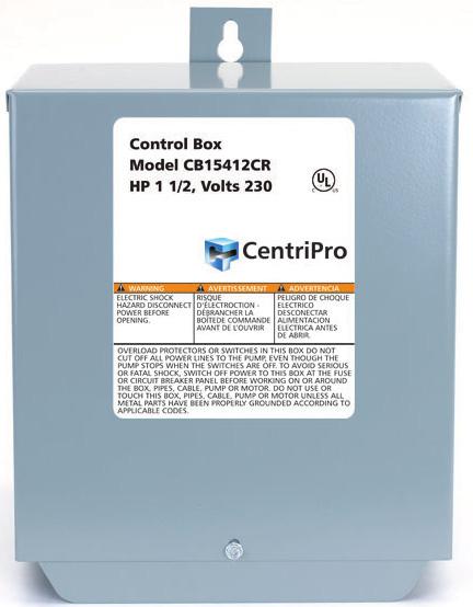
22 CSCR 1Ø CONTROL BOXES CAPACITOR START - CAPACITOR RUN FOR USE WITH 3 WIRE, 1Ø, 4" CENTRIPRO MOTORS AND 4" (6", 5 HP) FRANKLIN ELECTRIC MOTORS Control Box May May Replace May Replace Standard Standard Dual Element Enclosure Shipping Order HP KW Volts Replace Circuit Time Delay Dimensions RJ # FE # Fuse Wt. (lbs) Number GP # Breaker Fuse W x D x H (in) 50F311CB CB05412CR x 5.9 x S50N1CB, A50N1CB CB07412CR CB10412CR CB15412CR CB20412CR CB30412CR CB50412CR F311CB x 5.9 x S75N1CB, A75N1CB S100F311CB x 5.9 x S100N1CB, A100N1CB 150F311CB x 5.9 x S150N1CB, A150N1CB 200F311CB x 5.9 x S200N1CB, AS200T1CB 300F311CB S300N1CB x 5.9 x F311CB S500N1CB x 5.9 x K REPAIR PARTS Control Box Old Control Capacitor Capacitor Capacitor Capacitor Capacitor Overload Start Relay Order HP Volts Box Order Repair Part Mfd. Type Voltage Quantity Order Order Number Number Number Number 2 Number CB05412CR K Start 250 9K Run NA 9K458 CB07412CR K Start 250 9K Run N/A 9K458 CB10412CR K Start 250 9K Run N/A 9K458 CB15412CR K Start 250 9K Run K471 9K458 CB20412CR K Start 250 9K Run K481 9K458 9K Start 250 CB30412CR K482 9K Run 370 9K Start CB50412CR K483 9K Run K459 1 New ½ 1 HP CSCR control box is now in a larger enclosure, it is not in a quick disconnect style enclosure. 2 Overloads for 2, 3 and 5 HP CSCR boxes are sold prewired and soldered as an assembly. No field soldering or wiring required. Order Number 9K479 for 200/208 Volt Start Relay. PAGE 22
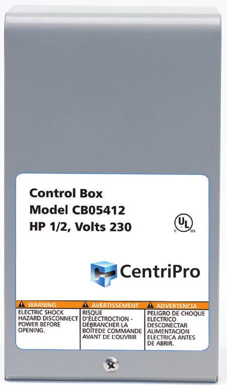
23 MAGNETIC CONTACTOR (MC) CONTROL BOXES FOR USE WITH 3 WIRE, 1Ø, 4" CENTRIPRO MOTORS AND 4" (6", 5 HP) FRANKLIN ELECTRIC MOTORS Standard Dual Element Enclosure Control Box Replaces Replaces Replaces Standard Shipping Order Number HP KW Volts Circuit Time Delay Dimensions GP # RJ # FE # Fuse Wt. (lbs) Breaker Fuse W x D x H (in) CB15412MC No Equal No Equal No Equal CB20412MC MC No Equal x 5.9 x CB30412MC MC S300N1CBC CB50412MC MC S500N1CBC x 6.7 x K REPAIR PARTS Capacitor Contactor Overload Start Relay Control Box Capacitor Capacitor Capacitor Capacitor HP KW Volts Repair Part Order Order Order Order Number Type Mfd. Voltage Quantity Number Number Number Number 9K447 Start CB15412MC K493 9K452 Run K458 9K447 Start K480 (S) CB20412MC K485 9K451 Run K472 (M) 230 9K453 Start K473 (S) CB30412MC K454 Run K474 (M) 9K459 9K455 Start K475 (S) CB50412MC K486 9K456 Run K476 (M) Repair parts above are compatible with and replace parts in old Goulds Pumps or Franklin Electric control boxes. Order Number 9K479 for 200/208 Volt Start Relay. PAGE 23
24 CSCR AND MC CONTROL BOX CHECK OUT CHECKING PROCEDURE: BE SURE POWER IS TURNED OFF. A. OVERLOAD (PUSH RESET BUTTONS TO MAKE SURE CONTACTS ARE CLOSED.) 1. OHMMETER SETTING: (R X 1) 2. TERMINAL CONNECTIONS: OHMMETER LEADS TO OVERLOAD TERMINALS. 3. OHMMETER READING: SHOULD NOT BE OVER 0.5 OHMS. B. CAPACITOR (DISCONNECT ONE LEAD FROM EACH CAPACITOR PRIOR TO CHECKING.) 1. OHMMETER SETTING: (R X 1000). 2. TERMINAL CONNECTIONS: INDIVIDUAL CAPACITOR TERMINALS. 3. OHMMETER READING: POINTER SHOULD SWING TOWARD ZERO THEN DRIFT BACK TOWARD INFINITY. C. RELAY COIL (DISCONNECT LEAD FROM TERMINAL 5) 1. OHMMETER SETTING: (R X 1000). 2. TERMINAL CONNECTIONS: 5 AND 2 ON RELAY. 3. OHMMETER READING: OHMS. D. RELAY CONTACT (DISCONNECT LEAD FROM TERMINAL 1) 1. OHMMETER SETTING: (R X 1). 2. TERMINAL CONNECTIONS; 1 AND 2 ON RELAY. 3. OHMMETER READING: SHOULD BE ZERO. E. MAGNETIC CONTACTOR ONLY (DISCONNECT 1 COIL LEAD) 1. OHMMETER SETTING: (R X 100). 2. CHECK COIL RESISTANCE: OHMS. 3. REMOVE CONTACT COVER AND INSPECT CONTACTS. ½, ¾ AND 1 HP 1Ø CSCR CONTROL BOX WIRING DIAGRAMS PAGE 24
25 1Ø CONTROL BOX WIRING DIAGRAMS 1½ HP STANDARD 1½ HP WITH MAGNETIC CONTACTOR 2 HP STANDARD 2 HP WITH MAGNETIC CONTACTOR PAGE 25
26 1Ø CONTROL BOX WIRING DIAGRAMS 3 HP STANDARD 3 HP WITH MAGNETIC CONTACTOR 5 HP STANDARD 5 HP WITH MAGNETIC CONTACTOR PAGE 26
27 PUMP TROUBLESHOOTING WARNING DISCONNECT AND LOCKOUT ELECTRICAL POWER BEFORE ATTEMPTING ANY SERVICE. FAILURE TO DO SO CAN CAUSE SHOCK, BURNS OR DEATH. Hazardous voltage can shock, burn or cause death. Symptom Probable Cause Recommended Action PUMP MOTOR NOT RUNNING 1. Motor thermal protector tripped a. Incorrect control box b. Incorrect or faulty electrical connections c. Faulty thermal protector d. Low voltage e. Ambient temperature of control box/ starter too high f. Pump bound by foreign matter g. Inadequate submergence 2. Open circuit breaker or blown fuse 3. Power source inadequate for load 4. Power cable insulation damage 5. Faulty power cable splice 1. Allow motor to cool, thermal protector will automatically reset a e. Have a qualified electrician inspect and repair, as required f. Pull pump, clean, adjust set depth as required g. Confirm adequate unit submergence in pumpage 2. Have a qualified electrician inspect and repair, as required 3. Check supply or generator capacity 4 5. Have a qualified electrician inspect and repair, as required LITTLE OR NO LIQUID DELIVERED BY PUMP 1. Faulty or incorrectly installed check valve 2. Pump air bound 3. Lift too high for pump 4. Pump bound by foreign matter 5. Pump not fully submerged 6. Well contains excessive amounts of air or gases 1. Inspect check valve, repair as required 2. Successively start and stop pump until flow is delivered 3. Review unit performance, check with dealer 4. Pull pump, clean, adjust set depth as required 5. Check well recovery, lower pump if possible 6. If successive starts and stops does not remedy, well contains excessive air or gases 7. Excessive pump wear 8. Incorrect motor rotation three phase only. 7. Pull pump and repair as required 8. Reverse any two motor electrical leads PAGE 27
28 AQUAVAR SOLO DATA CONTROLLER, BREAKER, GENERATOR SIZING Motor Controller Model ➁ Circuit Generator ➃ HP Voltage ➀ 1AS15 3AS20 3AS30 3AS50 Breaker ➂ (VA) ½ ¾ ½ ➀ Supply voltage must be 196 VAC 265 VAC. ➁ Shaded areas indicate which controller models can be used with which motors. Lighter shading indicates combinations where controller will limit peak performance to 85% of catalog value for pump/motor. ➂ Circuit Breaker or Dual Element Time Delay Fuse Size (Amps) protecting branch circuit supplying controller. ➃ Minimum size of single phase 240 V generator required. WIRE SIZING MAXIMUM CABLE LENGTHS IN FEET TO LIMIT VOLTAGE DROP TO 5% FOR 230 V SYSTEMS 5 Service Entrance to Controller Controller Motor Copper Wire Size 75ºC Insulation Exposed to a Maximum of 50ºC (122ºF) Ambient Temperature 6 Input HP /0 2/0 3/0 4/ V 1 PH ½ ¾ ½ * * * * * * * * Controller to Motor Controller Motor Copper Wire Size 75ºC Insulation Exposed to a Maximum of 50ºC (122ºF) Ambient Temperature 6 Output HP /0 2/0 3/0 4/ V 3 PH ½ ¾ ½ * Reduce lengths by 13% for 200 V systems. 6 Lengths in bold require 90ºC wire. Shading indicates 40º C maximum ambient. * Wire does not meet the N.E.C. ampacity requirement. The lengths in each of the Wire Sizing tables represent 100% of the allowable voltage drop when motor is running at full load. When sizing wire, the voltage drop of each wire segment must be included. The total must not exceed 100% of the allowable drop. Take for example a 1.5 HP motor with a distance from Service Entrance to Controller of 100' and 500' between the Controller and Motor. Service Entrance to Controller = 100' of 10 AWG (100/455) = 22 % (455' is from the S.E. to Controller chart) Controller to Motor = 500' of 12 AWG (500/709) = 71 % (709' is from the Controller to Motor chart) Total Drop (must be 100%) 93 % If the distance from the Controller to Motor was 600' (600/709) = 85% + 22% = 107%, we would need to use #10 wire for that segment, ex. 600/1126 = 53% + 22% (for 100' of #10) = 75% which is acceptable. It is also acceptable to use different wire sizes for the Buried and Well sections of wire. PAGE 28
29 AQUAVAR SOLO AND BALANCED FLOW REPAIR PARTS (See Ecom website or PRP, Repair Part Price Book, for Current Prices) Order Number Description 6K210 Gauge Guard - Transducer Protector 9K PSI Transducer V 9K PSI Transducer V 9K PSI Transducer V 9K Bar Transducer V (145 PSI) 9K524 SOLO and Balanced Flow Screw Repair Kit 9K525 SOLO and Balanced Flow Fan Repair Kit 9K545 10' Transducer Cable with Ground and GRN. Clamp 9K546 15' Transducer Cable with Ground and GRN. Clamp 9K547 25' Transducer Cable with Ground and GRN. Clamp 9K548 50' Transducer Cable with Ground and GRN. Clamp 9K ' Transducer Cable with Ground and GRN. Clamp 9K ' Transducer Cable with Ground and GRN. Clamp 9K ' Transducer Cable with Ground and GRN. Clamp 9K550 AquaBoost UIB 9K552 Balanced Flow and Aquavar SOLO UIB 9K575 Balanced Flow and Aquavar SOLO (all sizes) R05 Programmer 9K585 Water Sensor with Relay Contact 9K589 Over-Pressure Switch, PSI, Balanced Flow or S-Drive SERVICE FACTOR AMPS ALL MOTORS 230 Volt 200 Volt HP 1Ø 2-Wire 1Ø 3-Wire 3Ø 3Ø 1 Franklin Grundfos Franklin Grundfos Franklin Grundfos Franklin ½ 4.7/ N/A N/A N/A N/A N/A ¾ 6.4/ N/A / N/A ½ 11.0/ N/A N/A N/A N/A N/A N/A N/A N/A N/A N/A N/A N/A N/A N/A N/A Wire motors have Generation 1 and Generation 2 amp ratings, see motor nameplate or motor data sticker that was supplied with motor. 2. Amps are higher than controller overload range - use of these motors will current limit and provide reduced performance. PAGE 29
30 THREE PHASE MOTOR OPERATION ON VFD'S Variable Frequency Drive s (VFD) can be used with the 3 phase motor provided the operator meets the following criteria: 1) Maintain frequencies from 30HZ 60HZ. Do not operate below 30HZ for more than 1 second. 80 HZ operation can be used. 2) Ensure VFD is a PWM, IGBT, Volts per Hz scalar type and does not produce more than 500 volts dv/dt. 3) Use a load reactor (load filter) of 3% impedance or more on motor lead lengths of 50 wire feet or more. The Balanced Flow product already includes this in all models. 4) Follow all NEC, state, local or provincial electrical codes for Power Conversion Equipment wiring and installation. 5) Provide appropriate dedicated short circuit protection. Properly sized fuses or breaker disconnects. 6) Size wire according to NEC, state, local or provincial codes OR refer to manufacturers recommendation for wiring sizing. 7) Ensure proper flow around motor. 8) Maintain proper grounding of the motor back to drive and service entrance. Common ground throughout system! The following are some installation issues we have seen on returned Balanced Flow controllers which factory re-testing has shown to operate perfectly: Symptom Cycling, won't turn off, poor pressure control Cycling and wide pressure swings Poor performance Cause Incorrect tank pre-charge pressure Larger than recommended tank Motor running backwards Performance Improvement Suggestions: Installing a spring check valve on the pump side of the tank can reduce time to standby when flow stops. Poor pressure control can be caused by a clogged sensor. Not an issue for sensors 4/09 and later. Updating controllers built prior to 4/09 with latest Software, UIB and Sensor will improve reliability and performance. Updating software in controllers built after 4/09 may improve performance. Many generators produce voltages that exceed the 264VAC max rating of the controller. Test the generator output voltage when no load is connected. If the voltage exceeds 264VAC, do not use it with the BF controller! PAGE 30
31 AQUAVAR SOLO (formerly known as Balanced Flow) TROUBLESHOOTING Section 3 Installer Pre-Start Selections is used to indicate system status i.e. running, stopped, or faulted. When faulted, the status light will be red. The error code is the number of quick flashes followed by a 1 second pause. The number of flashes can be any number from 2 to 9. The error code will be repeated until cleared. Some errors will clear themselves with time. Others must be cleared manually by turning the power off for 1 minute. The following table describes the various errors that can occur. FAULT BLINK CODES Flashes Controller Status Description NO LIGHT None Low/No Check the input voltage to the controller. Measure the voltage between L1 and L2 Input Voltage using an AC Voltmeter. This voltage should be greater than 190Vac. None Controller is in Check the position of the RUN/PRG Jumper. The RUN/PRG Jumper is located Program Mode in the upper left hand corner of the controller. Refer to Figure 3. Flashes Controller Status Description Constant Standby/Low Voltage Placing this jumper in PRG mode (Program Mode) allows the user to update the controller s software through the the controller s software. When this jumper is in RUN mode (Run Mode), the controller will operate normally. If the controller is powered while in Program Mode, the status indicator will not turn on. To return the controller to Run Mode turn the power off to the controller and wait 5 minutes. Then move the RUN/PRG Jumper to RUN. Apply power to the controller. The controller is now in Run Mode. GREEN LIGHT CODES Constant Green Light indicates the pump is off. The system is in Standby mode when there is no flow in the system and the pressure setting has been reached. The system is in a Low Voltage condition when the line input voltage drops below 190VAC. Blinking Pump Running Flashing Green Light indicates the pump is running. Flashes Controller Status Fault Description Controller Action To clear the fault, turn off power to the controller, wait 1 minute, turn on power to the controller. If fault persists contact installer. RED LIGHT CODES This information is to be used by professional installers or qualified personnel only. Constant Controller Error Internal controller fault. Replace controller. PAGE 31
32 AQUAVAR SOLO (formerly known as Balanced Flow) TROUBLESHOOTING FAULT BLINK CODES (continued) Flashes Controller Status Description RED LIGHT CODES 2 Blinks Dry Well This fault can be caused by: The controller will automatically restart according to the chart shown on the right. If fault persists contact installer. 3 Blinks Sensor Fault This fault can be caused by: The controller will not run if the signal from the sensor is disconnected or out of tolerance. The controller will automatically restart when the signal is within tolerance. If fault persists contact installer. Water supply level in well falls below suction inlet of pump. Plugged suction screen. Restriction in pipe between pump and pressure sensor. Air bound pump see Purging System Incorrect setting of MAXIMUM SPEED switch. Be sure to set the MAXIMUM SPEED switch to 80 Hz when using mismatched pumps (water ends) and motors. Incorrect setting of MOTOR OVERLOAD SETTING (SFA) switch. Ensure the Motor Overload Setting (SFA) Switch is not set higher than the Service Factor Amps (SFA) listed on the motor nameplate. Need for Dry Well Power Calibration. Perform Dry Well Power Calibration as described in ADVANCED SETTINGS section. In systems where the motor operates at less than Service Factor Amps the controller may show a false dry well fault. See Dry Well Sensitivity Section. If problems persists, please verify supply capacity. The controller will automatically restart according to the chart below. Dry Well Fault Reset table: Fault 1 (Start Point) - resets after 1 minute Fault 2 - resets after 10 minutes Fault 3 - resets after 20 minutes Fault 4 - resets after 30 minutes Fault 5 - resets after 60 minutes and every 60 minutes thereafter Dry well can be reset by pressing both pushbuttons at the same time or by turning off the power. A fixed, 1 minute, restart time is also available. See ADVANCED SETTINGS section. Disconnected sensor. Disconnect sensor from sensor cable connector and reconnect to ensure a good connection. Disconnected sensor cable lead inside the controller. Check for loose wires where the sensor cable connects to the circuit board by tugging on each wire. Broken wire in the sensor cable. Miswired sensor cable. Check that the wires are connected to the correct terminals on the sensor connector. The correct location of the wires is indicated on the circuit board. B=Black, R=Red, W=White. Failed sensor. With the sensor cable connected to the circuit board, measure the DC voltage between the black and white wires of the sensor cable at the sensor connector. The voltage measured should be between 0.5Vdc and 4.5Vdc depending on the system pressure, see chart below. A vacuum on the sensor (transducer) of 17" Hg or more will cause a sensor fault, eliminate the vacuum. PAGE 32
33 AQUAVAR SOLO (formerly known as Balanced Flow) TROUBLESHOOTING FAULT BLINK CODES (continued) Flashes Controller Status Description 3 Blinks Sensor Fault (continued) RED LIGHT CODES Sensor Output vs. Applied Pressure Transducer Output (Volts DC) PSI Sensor 200 PSI Sensor Blinks Over Current This fault can be caused by: The controller will try to restart the motor three times before displaying this fault. To clear the fault, turn off power to the controller, wait 1 minute, turn on power to the controller. If fault persists contact installer. 5 Blinks Short Circuit This fault can be caused by: If this fault is detected while the pump is running, the controller will attempt to restart three times before displaying this fault. To clear the fault, turn off power to the controller, wait 1 minute, turn on power to the controller. If fault persists contact installer Pressure (PSI) Installing a 1Ø motor - system requires a 3Ø, 200 or 230 V motor. Mechanical binding from debris in pump. Electrical failure of the motor. Incorrect setting of MOTOR OVERLOAD SETTING (SFA) switch. A false bound pump error will be displayed if the switch is set too low. Pump wire insulation breaking down. Check insulation with megger. Verify the error by turning power to controller off for 1 minute and then on. Pump/Motor must be checked if fault persists. Electrical failure of the motor. Electrical failure of wiring between controller and motor. Verify the error by turning power to controller off for 1 minute and then on. If error persists, motor and wiring between controller and motor must be checked. Turn power off for 1 minute. Remove the three motor wires from the terminal block. Check wiring and motor for shorting phase to phase and phase to ground. Refer to motor s manual for information on resistance readings. PAGE 33
34 AQUAVAR SOLO (formerly known as Balanced Flow) TROUBLESHOOTING FAULT BLINK CODES (continued) Flashes Controller Status Description 6 Blinks Ground Fault WARNING This device does not provide personnel protection against shock. This function is intended for equipment protection only. The controller will not restart if displaying this fault. To clear the fault, turn off power to the controller, wait 1 minute, turn on power to the controller. If fault persists contact installer. The controller will automatically restart when the temperature reaches an acceptable level. If fault persists contact installer. The controller will not restart if displaying this fault. To clear the fault, turn off power to the controller, wait 1 minute, turn on power to the controller. If fault persists contact installer. The controller will not restart if displaying this fault. To clear the fault, turn off power to the controller, wait 1 minute, turn on power to the controller. If fault persists contact installer. RED LIGHT CODES This fault can be caused by: Electrical failure of the motor Electrical failure of wiring between controller and motor. Miswiring of motor cable. 7 Blinks Temperature This fault can be caused by: Verify the error by turning power to controller off for 1 minute and then on. If error persists, motor and wiring between controller and motor must be checked. Turn power off and wait 1 minute. Remove the three motor wires and ground wire from the terminal block. Check wiring and motor for shorting phase to ground using a megohmmeter ( megger ). A reading less than 200K Ohms indicates faulty insulation in the motor cable or motor. Test each to determine fault location. High ambient temperature. The maximum ambient temperature rating is 122ºF (50ºC). Low ambient temperature. The minimum ambient temperature rating is -4ºF (-20ºC). Check for a fan failure. The fan will turn on when the temperature inside the controller reaches 140ºF (60ºC). The fan will turn on for 1 second each time the controller starts the motor. If the fan never turns on, check fan connections and replace as needed. Ensure that the external fan intake filter is not blocked or clogged. It can be removed for cleaning and replacements are available. 8 Blinks Open Lead This fault can be caused by: Disconnected or broken wire between the controller and motor. 9 Blinks Low Pressure Cut-Off This fault can be caused by: Verify the error by turning power to controller off for 1 minute and then on. If error persists, motor and wiring between controller and motor must be checked. Turn power off for 5 minutes. Remove the three motor wires from the terminal block. Using an ohmmeter, measure the resistance from phase to phase. A disconnected or broken wire will be indicated by a high resistance reading (20 ohms or higher). Pressure 20 PSI below set point for 30 seconds. May be a broken pipe or tripped pressure relief valve. If 20 PSI or more pressure drop for 30 seconds is normal for the system, switch the broken pipe protection off or change system to prevent the pressure drop. PAGE 34
 master breaker or disconnect all leads from starter or control box to avoid damage to meter or electric shock hazard. 2.")
35 MEASURING INSULATION RESISTANCE 1. Set the scale lever to R x 100K (R x 100,000) and set the ohmmeter on zero. WARNING Open (turn off) master breaker or disconnect all leads from starter or control box to avoid damage to meter or electric shock hazard. 2. Connect an ohmmeter lead to any one of the motor leads and the other to the metal drop pipe. If the drop pipe is plastic, connect the ohmmeter lead to the metal well casing or ground wire. Megger What It Means 1. If the ohm value is normal, the motor windings are not grounded and the cable insulation is not damaged. 2. If the ohm value is below normal, either the windings are grounded or the cable insulation is damaged. Check the cable at the well seal as the insulation is sometimes damaged by being pinched. TABLE 1 Normal Ohm and Megohm Values (Insulation Resistance) Between All Leads and Ground Insulation resistance does not vary with rating. All motors of all HP, voltage and phase rating have similar values of insulation resistance. Condition of Motor and Leads Ohm Value Megohm Value A new motor (without drop cable). 20,000,000 (or more) 20.0 A used motor which can be reinstalled in the well. 10,000,000 (or more) 10.0 Motor in Well. Ohm readings are for drop cable plus motor. A new motor in the well. 2,000,000 (or more) 2.0 A motor in the well in reasonably good condition. 500,000-2,000, A motor which may have been damaged by lightning or with damaged leads. Do not pull the pump for this reason. A motor which definitely has been damaged or with damaged cable. The pump should be pulled and repairs made to the cable or the motor replaced. The motor will not fail for this reason alone, but it will probably not operate for long. A motor which has failed or with completely destroyed cable insulation. The pump must be pulled and the cable repaired or the motor replaced. 20, , ,000-20, Less than 10, PAGE 35
36 MOTOR WINDING RESISTANCE CHECKOUT Measuring Winding Resistance 1. Set the scale lever to R x 1 for values under 10 ohms. For values over 10 ohms, set the scale lever to R x 10. Zero balance the ohmmeter as described earlier on page 11. Open master breaker and CAUTION disconnect all leads from control box to pressure switch (Q-D type control, remove lid) to avoid damage to meter or electric shock hazard. 2. Connect the ohmmeter leads as shown below. TABLE 2 Cable Resistance Copper Cable Size DC Resistance of Cable per 100 Foot Length Ohms per Pair of Leads If aluminum cable is used the readings will be higher. Divide the ohm readings on this chart by 0.61 to determine the actual resistance of aluminum cable. RULE OF THUMB See motor data pages for motor resistance ratings. Add resistance of drop cable when checking pump in well. See Table 2 above. CABLE CHECKOUT Checking Cable and Splice 1. Submerge cable and splice in steel barrel of water with both ends out of water. 2. Set ohmmeter selector on RX100K and adjust needle to zero (0) by clipping ohmmeter leads together. 3. After adjusting ohmmeter, clip one ohmmeter lead to barrel and the other to each cable lead individually, as shown. 4. If the needle deflects to zero (0) on any of the cable leads, pull the splice up out of the water. If the needle falls back to ( ) (no reading) the leak is in the splice. 5. If leak is not in the splice, pull the cable out of the water slowly until needle falls back to ( ) (no reading). When the needle falls back, the leak is at that point. 6. If the cable or splice is bad, it should be repaired or replaced. What It Means Checking Cable and Splice Test Ohmmeter Set at R x 100K 1. If all ohm values are normal, the motor windings are neither shorted nor open, and the cable colors are correct. 2. If any one ohm value is less than normal, the motor is shorted. Attach this lead to Metal Tank 3. If any one ohm value is greater than normal, the winding or the cable is open or there is a poor cable joint or connection. 4. If some ohm values are greater than normal and some less, the leads are mixed. R x 100 R x 10 R x 1 OHMS ZERO OHMS R x 1000 R x 10K R x 100K PAGE 36


37 AMPROBE INSTRUCTIONS OHMMETER INSTRUCTIONS The Amprobe is a multi-range, combination ammeter and voltmeter. Voltmeter Scales: 150 VOLTS 600 VOLTS Ammeter Scales: 5 AMPS 40 AMPS 15 AMPS 100 AMPS 1. When used as an ammeter, the tongs are placed around the wire being measured with the rotary scale on the 100 amp range. Then rotate the scale back to the smaller ranges until an exact reading is indicated. 2. When used as a voltmeter, the two leads are clipped into the bottom of the instrument with the rotary scale on the 600 volt range. If the reading is less than 150 volts, rotate the scale to the 150 volt range to get a more exact reading. The Ohmmeter is used for measuring the electrical resistance of a wire circuit. The unit of measurement is called an Ohm. 1. The knob at the bottom of the Ohmmeter is adjustable through six ranges: RX 1 = R x 1 RX 10 = R x 10 RX 100 = R x 100 RX 1000 = R x 1,000 RX 10K = R x 10,000 RX 100K = R x 100, The round center knob is for the purpose of adjusting the instrument to zero (0) after clipping the two ohmmeter leads together. This must be done every time the range selection is changed. CAUTION If your ohmmeter is digital readout type, refer to the instructions that came with it. Use Ohmmeter only with POWER OFF. PAGE 37
 reading indicates bad fuse. WARNING Open master breaker and disconnect all leads from starter to avoid damage to meter or electric shock hazard.")

38 FUSE CHECKOUT 3 PHASE STARTER COIL CHECKOUT 1. Set R x Connect leads as shown. 3. Reading: Should register zero. What It Means Zero reading indicates fuse OK. Infinity ( ) reading indicates bad fuse. WARNING Open master breaker and disconnect all leads from starter to avoid damage to meter or electric shock hazard. Connect the ohmmeter leads as shown above. Coil with Ohmmeter 1. Set R x 1, Connect leads as shown. 3. Reading: Should register some value, Approximately ohms. What It Means Infinity reading indicates coil is open. Zero reading indicates coil is shorted. In either case, the coil should be replaced. A reading of ohms indicates coil is ok. PAGE 38
Motor Application and Installation Data
 Motor Application and Installation Data BMAID R8 INDEX GENERAL INFORMATION Storage, Frequency of Starts, Temperature Ratings, Flow Sleeve... 3-4 CENTRIPRO 4" SUBMERSIBLE MOTOR DATA Motor and Control Box
BULLETIN BAQSOLO AQUAVAR SOLO CONSTANT PRESSURE CONTROLLERS FOR: 1Ø 3-WIRE MOTORS, 1Ø 2-WIRE CENTRIPRO MOTORS, 3Ø MOTORS
 BULLETIN BAQSOLO AQUAVAR SOLO CONSTANT PRESSURE CONTROLLERS FOR: 1Ø 3-WIRE MOTORS, 1Ø 2-WIRE CENTRIPRO MOTORS, 3Ø MOTORS FEATURES NEMA 3R Enclosure: Rainproof, outdoor/ indoor rated enclosure. Current
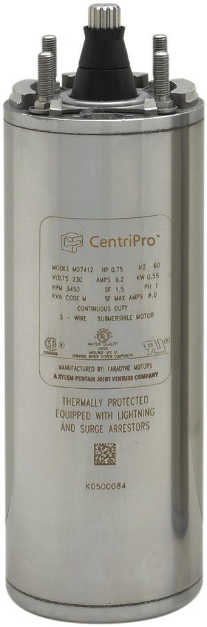
TECHNICAL BROCHURE BC3WIRE-G2 R4
 FEATURES 304 SS casing and end bells for corrosion resistance 304 SS casing and end bells for corrosion resistance Kingsbury type, 3 shoe, thrust bearing, see chart for ratings. Stainless steel, 17-4 PH
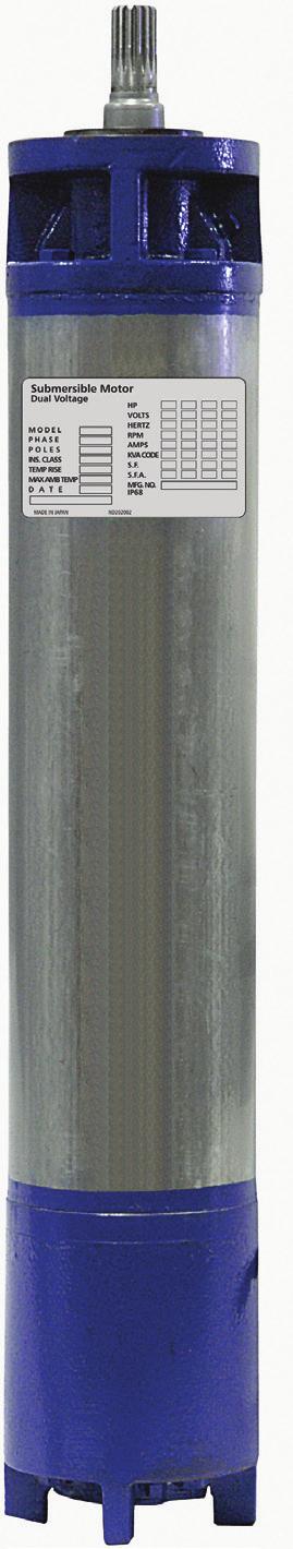
4" Motors and Controls
 4" Motors and Controls BRCP4MTR R1 4" CENTRIPRO MOTOR SINGLE-PHASE MOTORS: Two-Wire PSC Motors ½ HP, 115 V ½ - 1½ HP, 230 V Three-Wire Motors ½ HP, 115 V ½ - 5 HP, 230 V THREE-PHASE MOTORS: ½ - 10 HP (10
Service Manual SUBMERSIBLE PUMPS JET PUMPS GSSERVICE R5
 Service Manual SUBMERSIBLE PUMPS JET PUMPS GSSERVICE R5 TABLE OF CONTENTS Submersibles: (Pages 1 61) Page Safety Warnings...3-5 Typical Systems...6-7 Motor Cooling... 8 Troubleshooting...9-11 Amprobe Instructions...
INSTRUCTION MANUAL IM260 AQUAVAR SOLO 2 CONSTANT PRESSURE CONTROLLER INSTALLATION, OPERATION AND TROUBLESHOOTING MANUAL
 INSTRUCTION MANUAL IM260 AQUAVAR SOLO 2 CONSTANT PRESSURE CONTROLLER INSTALLATION, OPERATION AND TROUBLESHOOTING MANUAL Owner s Information Controller Model Number: Controller Serial Number: Pump Model
Installation & Operating Manual
 Installation & Operating Manual 6 WS Series Submersible Turbine Pumps Congratulations On Your Choice In Purchasing This Webtrol Pump 6/11 Edition Its Quality is unsurpassed in material and workmanship
2015 EDITION SUBMERSIBLE MOTORS AIM MANUAL. APPLICATION INSTALLATION MAINTENANCE 60 Hz, Single-Phase and Three-Phase Motors. franklinwater.
 0 EDITION AIM MANUAL SUBMERSIBLE MORS APPLICATION INSTALLATION 60 Hz, Single-Phase and Three-Phase Motors franklinwater.com All Motors System Troubleshooting Motor Does Not Start A. No power or incorrect
TECHNICAL BROCHURE BCP3PH R9. Three Phase 4" Motors, ½-10 HP 60 HERTZ, 3450 RPM
 TECHNICAL BROCHURE BCP3PH R9 Three Phase 4" Motors, ½-10 HP 60 HERTZ, 3450 RPM FEATURES 304 SS casing and end bells for corrosion resistance Kingsbury type, 3 shoe, thrust bearing, see chart for ratings
LANCASTER HYDRO-FORCE
 Bulletin # LHF4 10/14 LANCASTER HYDRO-FORCE 4 Submersible Motors Single Phase, 230 Volt, 60 Hertz 2-Wire Motors 3-Wire Motors Control Boxes for use with 3-Wire Motors TECHNICAL BULLETIN PAGE 1 INDEX Technical
Variable Speed Product Line
 Variable Speed Product Line BRCPVFD R1 Variable Speed Product Line Since 1997, CentriPro has been providing variable speed pump control solutions to its customers. The first product was the Aquavar variable
331-SV. User Manual THREE PHASE DUPLEX LIFT STATION CONTROL PANEL WITH STATIONVIEW CONTROLLER. Ashland, OH
 331-SV User Manual THREE PHASE DUPLEX LIFT STATION CONTROL PANEL WITH STATIONVIEW CONTROLLER Ashland, OH 800-363-5842 WWW.PRIMEXCONTROLS.COM Warranty void if panel is modified. Call factory with servicing
INSTALLATION INSTRUCTIONS FOR SYMCOM MODEL 231-P-INSIDER
 INSTALLATION INSTRUCTIONS FOR SYMCOM MODEL 231-P-INSIDER The PumpSaver Plus Model 231-P-INSIDER fits inside 1/3 1hp, 230V Franklin, Pentek, or CentriPro control boxes. PumpSavers are designed to protect
TECHNICAL BROCHURE BSPDDRIVE. Aquavar SPD (Single Pump Drive) SIMPLEX VARIABLE SPEED PUMP CONTROLLER FOR SUBMERSIBLE AND CENTRIFUGAL PUMPS
 SIMPLEX VARIABLE SPEED PUMP CONTROLLER FOR SUBMERSIBLE AND CENTRIFUGAL PUMPS") TECHNICAL BROCHURE BSPDDRIVE C U L US Aquavar SPD (Single Pump Drive) SIMPLEX VARIABLE SPEED PUMP CONTROLLER FOR SUBMERSIBLE AND CENTRIFUGAL PUMPS Aquavar SPD variable speed, constant pressure pump controller
TECHNICAL BROCHURE BSPDDRIVE C U L US Aquavar SPD (Single Pump Drive) SIMPLEX VARIABLE SPEED PUMP CONTROLLER FOR SUBMERSIBLE AND CENTRIFUGAL PUMPS Aquavar SPD variable speed, constant pressure pump controller
M T E C o r p o r a t i o n. dv/dt Filter. Series A VAC USER MANUAL PART NO. INSTR REL MTE Corporation
 M T E C o r p o r a t i o n dv/dt Filter Series A 440-600 VAC USER MANUAL PART NO. INSTR - 019 REL. 041119 2004 MTE Corporation IMPORTANT USER INFORMATION NOTICE The MTE Corporation dv/dt Filter is designed
ITT Commercial, Irrigation and Agricultural Water CentriPro Features SINGLE PHASE: THREE PHASE: NOTE: See color brochure (BRCP6SM) for
 for") Commercial, Irrigation and Agricultural Water CentriPro 6" Single Phase s 6-10" Three Phase s Features SINGLE PHASE: Single Phase, 6 motors available in 5 15 HP, 230 volt models. Require CentriPro Control
Commercial, Irrigation and Agricultural Water CentriPro 6" Single Phase s 6-10" Three Phase s Features SINGLE PHASE: Single Phase, 6 motors available in 5 15 HP, 230 volt models. Require CentriPro Control
M T E C o r p o r a t i o n MATRIX FILTER. SERIES B Volts, 50HZ USER MANUAL PART NO. INSTR REL MTE Corporation
 M T E C o r p o r a t i o n MATRIX FILTER SERIES B 380-415 Volts, 50HZ USER MANUAL PART NO. INSTR - 015 REL. 060628 2006 MTE Corporation IMPORTANT USER INFORMATION NOTICE The MTE Corporation Matrix Filter
PENTEK XE-6. OWNER S MANUAL 6 Submersible Motors 293 WRIGHT STREET, DELAVAN, WI PH: PENTEK
 OWNER S MANUAL 6 Submersible Motors PENTEK XE-6 232852 DRINKING WATER SYSTEM COMPONENT ANSI/NSF 61-G 3RZE 293 WRIGHT STREET, DELAVAN, WI 53115 WWW.PUMPS.COM PH: 1-866-9 PENTEK 2015 Pentair Ltd. All Rights
ITT. Goulds Pumps 45J and 70J. Engineered for life B45-70J. Residential Water Systems. Features. 60 Hz High Capacity Flat Bowl 6" Submersible Pumps
 B45-7J Goulds Pumps 45J and 7J Hz High Capacity Flat Bowl 6" Submersible Pumps For 6" and larger wells Goulds Pumps is a brand of Corporation. www.goulds.com Engineered for life Features n Powered for
Table of Contents 1 1. GENERAL SAFETY GUIDELINES. 2. NOMENCLATURE 2.1 Motors 2.2 Variable/High Speed Drives 2.3 Submersible Motor Controls
 Table of Contents 1 1. GENERAL SAFETY GUIDELINES 2. NOMENCLATURE 2.1 Motors 2.2 Variable/High Speed Drives 2.3 Submersible Motor Controls 3. INSTALLATION & SETUP 3.1 General Installation Guidelines 3.2
INSTALLATION INSTRUCTIONS FOR SYMCOM'S MODEL 777-HVR-SP ELECTRONIC OVERLOAD RELAY
 CONNECTIONS INSTALLATION INSTRUCTIONS FOR SYMCOM'S MODEL 777-HVR-SP ELECTRONIC OVERLOAD RELAY BE SURE POWER IS DISCONNECTED PRIOR TO INSTALLATION!! FOLLOW NATIONAL, STATE AND LOCAL CODES! READ THESE INSTRUCTIONS
Motors " GRUNDFOS GROUNDWATER SERVICE MANUAL CONTENTS. Grundfos Motor Specifications... Page 2
 GRUNDFOS GROUNDWATER SERVICE MANUAL Motors 4-6-8-10" CONTENTS Grundfos Motor Specifications... Page 2 Electrical Requirements... Page 8 -Transformer Capacity Maximum Motor Cable Length... Page 10 Full
Matrix APAX. 380V-415V 50Hz TECHNICAL REFERENCE MANUAL
 Matrix APAX 380V-415V 50Hz TECHNICAL REFERENCE MANUAL WARNING High Voltage! Only a qualified electrician can carry out the electrical installation of this filter. Quick Reference ❶ Performance Data Pages
Installation and Operating Instructions
 Installation and Operating Instructions Congratulations on your purchase of a Franklin Electric pump protection system. Pumptec-Plus is the most sophisticated pump protection system on market today. It
6" Single Phase Motors 6-10" Three Phase Motors
 TECHNICAL BROCHURE BCP6-10MTR R2 FEATURES SINGLE PHASE: Single Phase, 6 motors available in 5 15 HP, 230 volt models. Require Control Boxes as shown on Order Number chart. THREE PHASE: Three Phase, 6,
Installation and Operating Instructions
 PUMP PROTECTION SYSTEM Installation and Operating Instructions Congratulations on your purchase of a Franklin Electric pump protection system. Pumptec-Plus is the most sophisticated pump protection system
M T E C o r p o r a t i o n MATRIX FILTER. SERIES B Volts, 50HZ USER MANUAL PART NO. INSTR REL MTE Corporation
 M T E C o r p o r a t i o n MATRIX FILTER SERIES B 380-415 Volts, 50HZ USER MANUAL PART NO. INSTR - 015 REL. 040709 2003 MTE Corporation IMPORTANT USER INFORMATION NOTICE The MTE Corporation Matrix Filter
SS/SSH Submersible Pump. Owner s Manual
 Est. 1985 www.aquascience.net SS/SSH Submersible Pump Owner s Manual 4 SUBMERSIBLE PUMP INSTALLATION INSTRUCTIONS IMPORTANT: Read this manual carefully before installing or operating the pump. Review instructions
EPS-ECONOMY PUMP STARTER
 EPS-ECONOMY PUMP STARTER NEMA 1 & 3R ENCLOSURES franklinwater.com EPS-ECONOMY PUMP STARTER - 1 & 3 PHASE, 50/60HZ, 200-600 VAC, 1-80A The enhanced Franklin Electric Economy Pump Starter (EPS) provides
INSTRUCTION MANUAL IM248. High Temp Sump Pump INSTALLATION, OPERATION AND MAINTENANCE INSTRUCTIONS
 INSTRUCTION MANUAL IM248 High Temp Sump Pump INSTALLATION, OPERATION AND MAINTENANCE INSTRUCTIONS TABLE OF CONTENTS SUBJECT PAGE Introduction...3 Safety Instructions...3 Performance and Motor Details...3
Redi-Flo4. Stainless Steel Submersible Pumps for Environmental Applications GRUNDFOS INSTRUCTIONS. US Installation and operating instructions
 GRUNDFOS INSTRUCTIONS Redi-Flo4 Stainless Steel Submersible Pumps for Environmental Applications US Installation and operating instructions Please leave these instructions with the pump for future reference.
MATRIX FILTER USER MANUAL. SERIES D 600 Volts, 60HZ PART NO. INSTR 026 REL MTE Corporation
 MATRIX FILTER SERIES D 600 Volts, 60HZ USER MANUAL PART NO. INSTR 026 REL. 080920 2008 MTE Corporation IMPORTANT USER INFORMATION NOTICE The MTE Corporation Matrix Filter is designed for harmonic mitigation
SAVE THESE INSTRUCTIONS
 READ AND FOLLOW ALL SAFETY INSTRUCTIONS! SAVE THESE INSTRUCTIONS AND DELIVER TO OWNER AFTER INSTALLATION IMPORTANT SAFEGUARDS! When using electrical equipment, basic safety precautions should always be
OWNERS GUIDE TO INSTALLATION AND OPERATION OF 1/2-5 HP, 5, 7, 10, 15, 19 & 27 GPM 4 SUBMERSIBLE PUMPS
 FW0080 0511 Supersedes 0610 OWNERS GUIDE TO INSTALLATION AND OPERATION OF 1/2-5 HP, 5, 7, 10, 15, 19 & 27 GPM 4 SUBMERSIBLE PUMPS IL0632 WARNING IMPORTANT SAFETY INSTRUCTIONS RULES FOR SAFE INSTALLATION
SineWave Guardian TM 380V 600V INSTALLATION GUIDE. Quick Reference. ❶ How to Install Pages 6 17 ❷ Startup/Troubleshooting Pages WARNING
 SineWave Guardian TM 380V 600V INSTALLATION GUIDE FORM: SWG-IG-E REL. October 2018 REV. 003 2018 MTE Corporation High Voltage! Only a qualified electrician can carry out the electrical installation of
North America Phase Converters & Electrical Supply
 North America Phase Converters & Electrical Supply OPERATION AND INSTALLATION MANUAL ROTARY PHASE CONVERTERS (Models PL, UL & CP) 240 VOLTS WARNING: To reduce the risk of injury, the user must read and
REFERENCE MANUAL FORM: MX-TRM-E REL REV MTE
 Matrix APAX 380V-415V 50Hz TECHNICAL REFERENCE MANUAL FORM: MX-TRM-E REL. September 2014 REV. 002 2014 MTE Corporation WARNING High Voltage! Only a qualified electrician can carry out the electrical installation
MATRIX FILTER USER MANUAL. SERIES D 600 Volts, 60HZ PART NO. INSTR 026 REL REV MTE Corporation
 MATRIX FILTER SERIES D 600 Volts, 60HZ USER MANUAL PART NO. INSTR 026 REL. 120628 REV. 007 2012 MTE Corporation Matrix Series D User s Manual 600VAC IMPORTANT USER INFORMATION NOTICE The MTE Corporation
PHASE PERFECT PHASE CONVERTERS OPERATION & INSTALLATION MANUAL PHASE TECHNOLOGIES, LLC
 PHASE PERFECT PHASE CONVERTERS OPERATION & INSTALLATION MANUAL PHASE TECHNOLOGIES, LLC 1 DANGER: HIGH VOLTAGE Electric shock could result in death or injury. qualified personnel for installation. Please
MotorGuard. KMG High Performance Output Sine Wave Filter. Installation, Operation, and Maintenance Manual
 MotorGuard KMG High Performance Output Sine Wave Filter Installation, Operation, and Maintenance Manual MotorGuard KMG High Performance Output Sinewave Filter Installation, Operation, and Maintenance Manual
SUPPLEMENT MANUAL IM250R03. AQUAVAR CPC SUPPLEMENT A - Variable Speed Drive SUPPLEMENT TO THE INSTALLATION AND OPERATION MANUAL (IM167)
") SUPPLEMENT MANUAL IM250R03 AQUAVAR CPC SUPPLEMENT A - Variable Speed Drive SUPPLEMENT TO THE INSTALLATION AND OPERATION MANUAL (IM167) TABLE OF CONTENTS SAFETY Use of Warnings and Notes...3 INSTALLATION
SUPPLEMENT MANUAL IM250R03 AQUAVAR CPC SUPPLEMENT A - Variable Speed Drive SUPPLEMENT TO THE INSTALLATION AND OPERATION MANUAL (IM167) TABLE OF CONTENTS SAFETY Use of Warnings and Notes...3 INSTALLATION
User s Manual. ACH550-CC/CD Packaged Drive with Classic Bypass Supplement for ACH550-UH HVAC User s Manual
 User s Manual ACH550-CC/CD Packaged Drive with Classic Bypass Supplement for ACH550-UH HVAC User s Manual ii ACH550-CC/CD Packaged Drive with Classic Bypass ACH550 Drive Manuals GENERAL MANUALS ACH550-UH
MODEL 235P INSTALLATION INSTRUCTIONS. Revision B1 Rapid City, SD, USA, 08/2009 II_235P_B1
 INSTALLATION INSTRUCTIONS Revision B1 Rapid City, SD, USA, 08/2009 MODEL 235P II_235P_B1 2880 North Plaza Drive, Rapid City, South Dakota 57702 (800) 843-8848 (605) 348-5580 fax (605) 348-5685 BE SURE
Application Engineering
 Application Engineering February, 2009 Copeland Digital Compressor Controller Introduction The Digital Compressor Controller is the electronics interface between the Copeland Scroll Digital Compressor
SUBMERSIBLE ELECTROPUMPS 50 HZ
 L.Nemitsas Ltd - Head Office P.O.Box 54436 3724 Limassol, Cyprus Tel: +357 25569225 & 25569226 Fax: +357 25 396955 L.Nemitsas Ltd - Nicosia Branch F.Tsigaridi 19 Str. 2235, Latsia - Nicosia Tel: +357-22467366
Matrix AP 400V 690V INSTALLATION GUIDE. Quick Reference. ❶ How to Install Pages 6 20 ❷ Startup/Troubleshooting Pages WARNING
 Matrix AP 400V 690V INSTALLATION GUIDE FORM: MAP-IG-E REL. May 2017 REV. 002 2017 MTE Corporation WARNING High Voltage! Only a qualified electrician can carry out the electrical installation of this filter.
Application Engineering
 Application Engineering March 2011 Copeland Digital Compressor Controller Introduction The Digital Compressor Controller is the electronics interface between the Copeland Scroll Digital compressor or the
INSTRUCTION MANUAL IM245. RGS2012E1 S or E Retrofit Kit SUBMERSIBLE GRINDER PUMP INSTALLATION, OPERATION AND TROUBLESHOOTING MANUAL
 INSTRUCTION MANUAL IM245 RGS2012E1 S or E Retrofit Kit SUBMERSIBLE GRINDER PUMP INSTALLATION, OPERATION AND TROUBLESHOOTING MANUAL SAFETY INSTRUCTIONS TO AVOID SERIOUS OR FATAL PERSONAL INJURY OR MAJOR
OWNERS GUIDE TO INSTALLATION AND OPERATION GPM and GPM GPM SUBMERSIBLE PUMPS
 OWNERS GUIDE TO INSTALLATION AND OPERATION 4 3-8 GPM and 6 0-20 GPM 8 32-400 GPM SUBMERSIBLE PUMPS WARNING IMPORTANT SAFETY INSTRUCTIONS RULES FOR SAFE INSTALLATION AND OPERATION 1. Read these warnings
MATRIX FILTER USER MANUAL. SERIES D 480 Volts, 60HZ PART NO. INSTR 024 REL REV MTE Corporation
 MATRIX FILTER SERIES D 480 Volts, 60HZ USER MANUAL PART NO. INSTR 024 REL. 120628 REV. 012 2012 MTE Corporation Matrix Series D User s Manual 480VAC IMPORTANT USER INFORMATION NOTICE The MTE Corporation
High Frequency SineWave Guardian TM
 High Frequency SineWave Guardian TM 380V 480V INSTALLATION GUIDE FORM: SHF-IG-E REL. January 2018 REV. 002 2018 MTE Corporation High Voltage! Only a qualified electrician can carry out the electrical installation
ITT. Goulds Pumps 70L, 90L, 150L, 200L, 300L Stainless Steel 6" Submersible Pumps. Engineered for life. Residential Water Systems. 60 Hz High Capacity
 Goulds Pumps 7L, 9L, 15L, 2L, 3L Stainless Steel 6" Submersible Pumps 6 Hz High Capacity For 6" and larger wells Goulds Pumps is a brand of ITT Residential and Commercial Water. www.goulds.com Engineered
POWER FACTOR CORRECTION MOTOR LOAD (ML) FIXED CAPACITOR
 FIXED CAPACITOR") User s Manual for The POWER FACTOR CORRECTION MOTOR LOAD (ML) FIXED CAPACITOR 301 Gaddis Boulevard Dayton, Ohio 45403 U.S. Toll Free 866-261-1191 (937) 253-1191 Fax: (937) 253-1723 Web site: www.stacoenergy.com
User s Manual for The POWER FACTOR CORRECTION MOTOR LOAD (ML) FIXED CAPACITOR 301 Gaddis Boulevard Dayton, Ohio 45403 U.S. Toll Free 866-261-1191 (937) 253-1191 Fax: (937) 253-1723 Web site: www.stacoenergy.com
Continuing Education Course #206 Introduction to Designing Machine Control Systems Part 2
 1 of 5 Continuing Education Course #206 Introduction to Designing Machine Control Systems Part 2 1. Continuing to answer the following questions indicates that you understands that the presented material
MODEL 500S10HP86 B13 MODEL 300S10HP66 B13. 6 & 8 Pump Ends GPM Stainless Steel Pumps 6/13
 MODEL 500S10HP86 B13 MODEL 300S10HP66 B13 6 & 8 Pump Ends 90-500 GPM Stainless Steel Pumps 6/13 Table of Contents Page General Information... 2 Order / Identifing Pump Ends... 3 Stainless Steel Pump Ends
SUBMERSIBLE PUMPS
 motralec rue Lavoisier. ZA Lavoisier. 5223 HERBLAY CEDEX Tel. : 1.3.7.65. / Fax. : 1.3.7.68 Demande de prix / e-mail : service-commercial@motralec.com www.motralec.com SUBMERSIBLE PUMPS - 6-8 INSTALLATION,
ITT. Goulds Pumps 65L, 95L, 120L, 160L, 250L, 320L 6" Stainless Steel Submersible Pumps. Engineered for life B65-320L. Residential Water Systems
 B65-32L ITT Residential Water Systems Goulds s 65L, 95L, 12L, 16L, 2L, 32L 6" Stainless Steel Submersible s 6 Hz High Capacity For 6" and larger wells Goulds s is a brand of ITT Corporation. www.goulds.com
6 Submersible Motors Hi-Temp 90
 Applications These motors are built for dependable operation in 6 diameter or larger water wells, in applications with higher temperature, high thrust or low flow. Basic Features Able to operate in water
MODEL 233P/111P/233P-1.5
 II-111-233-15P-B INSTALLATION INSTRUCTIONS Revision C Rapid City, SD, USA, 07/2015 MODEL 233P/111P/233P-1.5 BE SURE POWER IS DISCONNECTED PRIOR TO INSTALLATION! FOLLOW NATIONAL, STATE AND LOCAL CODES.
ACCESSORY KIT INSTALLATION INSTRUCTIONS
 ACCESSORY KIT INSTALLATION INSTRUCTIONS Low Ambient Accessory For Air Cooled Split-System Air Conditioners YD360/480/600, YJ-30/-40/-50 and J30/40/50 YD Models 642546-UAI-A-080 GENERAL Standard operation
MODEL 422 Submersible Pump Controller
 MODEL 422 Submersible Pump Controller Monitors True Motor Power (volts x current x power factor) Detects Motor Overload or Underload Operates on 120 or 240VAC, Single-phase or 3-phase Built-in Trip and
Mizer Single Pump and Starter Box
 Mizer Single Pump and Starter Box Table of Contents Line Diagram... 2 Overview... 3 Booster Pump Specifications... 3 Water... 3 Electrical... 3 Models... 3 Mounting... 4 Electrical... 6 Motor Rotation...
Motor. Document # Vari-Green Motor and Controls. Table of Contents. Features, Operation, Wiring and Troubleshooting
 Document #473681 Vari-Green Motor and Controls Installation, Operation and Maintenance Manual Please read and save these instructions for future reference. Read carefully before attempting to assemble,
Water to Water Geothermal Heat Pump 3-Phase Models Both 208 & 480
 Installer Water to Water Geothermal Heat Pump 3-Phase s Both 208 & 480 Installation Instructions : THA-***-2 (208, 3-Phase) THT-***-2 (208, 3-Phase) THA-***-3 (480, 3-Phase) THT-***-3 (480, 3-Phase) This
User s Manual. ACS550-CC Packaged Drive with Bypass Supplement for ACS550-01/U1 Drives User s Manual
 User s Manual ACS550-CC Packaged Drive with Bypass Supplement for ACS550-01/U1 Drives User s Manual ii ACS550-CC Packaged Drive with Bypass ACS550 Drive Manuals GENERAL MANUALS ACS550-01/U1 Drives User's
The Traveler Series: Wanderer
 The Traveler Series: Wanderer RENOGY 30A Charge Controller Manual 2775 E. Philadelphia St., Ontario, CA 91761 1-800-330-8678 Version: 2.0 Important Safety Instructions Please save these instructions. This
TECHNICAL BROCHURE BAQUACPC. Aquavar CPC VARIABLE SPEED CENTRIFUGAL PUMP CONTROLLER
 TECHNICAL BROCHURE BAQUACPC Aquavar CPC VARIABLE SPEED CENTRIFUGAL PUMP CONTROLLER Introduction The Aquavar CPC (Centrifugal Pump Controller) from incorporates the latest state-of-the-art Aquavar technology,
SOLAR LIGHTING CONTROLLER SUNLIGHT MODELS INCLUDED IN THIS MANUAL SL-10 SL-10-24V SL-20 SL-20-24V
 SOLAR LIGHTING CONTROLLER OPERATOR S MANUAL SUNLIGHT MODELS INCLUDED IN THIS MANUAL SL-10 SL-10-24V SL-20 SL-20-24V 10A / 12V 10A / 24V 20A / 12V 20A / 24V 1098 Washington Crossing Road Washington Crossing,
Electronic Products ELECTRONIC MAINTENANCE
 SubDrive2W, 75, 100, 150, 300, MonoDrive, and MonoDrive XT Should an application or system problem occur, built-in diagnostics will protect the system. The FAULT light or digital display on the front of
Owners Manual. Features
 Owners Manual Pumptec is a microcomputer based pump protection device that continuously monitors motor load and power line conditions to provide protection against dry well conditions, waterlogged tanks,
MATRIX FILTER USER MANUAL. SERIES D 400 Volts, 50HZ PART NO. INSTR 025 REL REV MTE Corporation
 MATRIX FILTER SERIES D 400 Volts, 50HZ USER MANUAL PART NO. INSTR 025 REL. 110624 REV. 006 2011 MTE Corporation IMPORTANT USER INFORMATION NOTICE The MTE Corporation Matrix Filter is designed for harmonic
3 Phase Smart Controller
 3 Phase Smart Controller Installation and Owner s Manual STP-SCIII 208-230 VAC, 60Hz, 120 Volt Coil Franklin Fueling 3760 Marsh Rd. Madison WI 53718 USA Tel: +1 608 838 8786 800 225 9787 Fax: +1 608 838
Hydrovar and Packaged Hydrovar
 Hydrovar and Packaged Hydrovar MOTOR MOUNT VARIABLE SPEED PUMP CONTROLLER AND INTEGRATED PUMP PACKAGES BRHYDROVAR R3 Goulds Water Technology Hydrovar and Packaged Hydrovar Hydrovar Variable Speed Drives
Motor Protection. Voltage Unbalance & Single-Phasing
 For Summary of Suggestions to Protect Three-Phase Motors Against Single-Phasing see the end of this section, page 137. Historically, the causes of motor failure can be attributed to: Overloads 30% Contaminants
Installation & Operating Manual
 Installation & Operating Manual VN Series Non-Clog Pumps Congratulations On Your Choice In Purchasing This Webtrol Pump 10/15 Edition Its Quality is unsurpassed in material and workmanship and has been
User s Manual. ACH550-CC/CD Packaged Drive with Classic Bypass Supplement for ACH550-UH HVAC User s Manual
 User s Manual ACH550-CC/CD Packaged Drive with Classic Bypass Supplement for ACH550-UH HVAC User s Manual ii ACH550-CC/CD Packaged Drive with Classic Bypass ACH550 Drive Manuals GENERAL MANUALS ACH550-UH
INSTALLATION & OPERATION MANUAL. Fan Powered Terminals VAV TERMINALS. Redefine your comfort zone.
 INSTALLATION & OPERATION MANUAL Fan Powered Terminals VAV TERMINALS IOM FAN POWERED TERMINALS Receiving Inspection After unpacking the terminal, check it for shipping damage. If any shipping damage is
ECU-02 Ver2.1 Automatic Engine Control Unit Operators Manual
 ECU-02 Ver2.1 Automatic Engine Control Unit Operators Manual Headquarters : No.3, Lane 201, Chien Fu St., Chyan Jenn Dist., Kaohsiung, TAIWAN Tel : + 886-7-8121771 Fax : + 886-7-8121775 URL : http://www.kutai.com.tw
Aquavar e-abii. TECHNICAL BROCHURE BAQUAeABII VARIABLE SPEED CONSTANT PRESSURE SYSTEMS
 TECHNICAL BROCHURE BAQUAeABII * Available up to 1 GPM systems Aquavar e-abii VARIABLE SPEED CONSTANT PRESSURE SYSTEMS 1 HP thru 5 HP - Pressure Booster Packages 1AB2 and 2AB2 Prewired Pump/Controller Kits
DIN Rail UPS Model: DIN-UPS Installation/Operation Manual
 DIN Rail UPS Model: DIN-UPS 24-10 Installation/Operation Manual Table of Contents Section Page Section Page Quick Start 2 1) General Information 4 Materials Provided 4 Optional Equipment 4 2) Safety Information
BRAQCPC IT T. Goulds Pumps AQUAVAR CPC. Variable Speed Centrifugal Pump Controller. Engineered for life
 BRAQCPC IT T Goulds Pumps AQUAVAR CPC Variable Speed Centrifugal Pump Controller Engineered for life Goulds Pumps Variable Speed Centrifugal Pump Controller 2 Introduction The Aquavar CPC (Centrifugal
Application Engineering Europe
 Date of last update: Feb-12 Ref: D7.8.4/0112-0212/E Application Engineering Europe CORESENSE DIAGNOSTICS FOR STREAM REFRIGERATION COMPRESSORS 1/17 1 Introduction CoreSense is an ingredient brand name for
INSTALLATION, OPERATION, SERVICE & REPAIR PARTS MANUAL FOR
 INSTALLATION, OPERATION, SERVICE & REPAIR PARTS MANUAL FOR RED JACKET Extracta Remote Gasoline Pumps Models P75S17-3, P150S17-3 & X4P150S17 380 Volt, 3 Phase, 50 Hertz by 051-138 Rev. C ELECTRICAL SERVICE
Quick Start Guide TS 910
 Quick Start Guide TS 910 DANGER HAZARD OF ELECTRICAL SHOCK, EXPLOSION, OR ARC FLASH Read and understand this quick start guide before installing and operating the transfer switch The installer is responsible
Quick Start Guide TS 910 & TS 920
 Quick Start Guide TS 910 & TS 920 DANGER HAZARD OF ELECTRICAL SHOCK, EXPLOSION, OR ARC FLASH Read and understand this quick start guide before installing and operating the transfer switch The installer
Beaver Power Factor Correction Capacitors
 Beaver Power Factor Correction Capacitors Beaver Low Voltage Power Factor Correction Capacitors are designed for long life and are made with the highest quality materials. All units are assembled in Canada
Centrifugal Constant Pressure Control
 Operating Instructions & Parts Manual Please read and save these instructions. Read carefully before attempting to assemble, install, operate or maintain the product described. Protect yourself and others
Submersible Motors, Controls and Accessories
 Submersible Motors, Controls and Accessories Canada 2012 List Prices P8062WS-CN 02/01/12 Effective: February 1, 2012 Supersedes All Previous Price Lists Table of Contents Description Page 4" XE Series
User s Manual. ACS550-CC Packaged Drive with Bypass Supplement for ACS550-01/U1 Drives User s Manual
 User s Manual ACS550-CC Packaged Drive with Bypass Supplement for ACS550-01/U1 Drives User s Manual ii ACS550-CC Packaged Drive with Bypass ACS550 Drive Manuals GENERAL MANUALS ACS550-01/U1 Drives User's
VERTICAL MULTI-STAGE CENTRIFUGAL PUMPS
 Installation and Operating Instructions VERTICAL MULTI-STAGE CENTRIFUGAL PUMPS Models 1, 3, 5, 10, 15, 20, 32, 45, 64, 90 1. Model numbering and nameplate format 1.1 Model numbering Example: SBI / SBN
4" SUBMERSIBLE PUMP 4" SUBMERSIBLE PUMP. "GS" series. "ST" series. "SL" series. ST Series (stainless steel) SL Series (thermoplastic)
 SL Series (thermoplastic)") 4" SUBMERSIBLE PUMP 4" SUBMERSIBLE PUMP ST / GS SERIES (stainless steel) SL SERIES (thermoplastic) The "ST / GS / SL" series are built with such precision that they provide a superior output for many years.
4" SUBMERSIBLE PUMP 4" SUBMERSIBLE PUMP ST / GS SERIES (stainless steel) SL SERIES (thermoplastic) The "ST / GS / SL" series are built with such precision that they provide a superior output for many years.
EPS-ECONOMY PUMP STARTER
 EPS-ECONOMY PUMP STARTER 1 & 3 Phase, 50/60Z, 200-600 VAC, 1-80A The enhanced Franklin Electric Economy Pump Starter (EPS) provides a simple and dependable starting option with a wide electronic overload
Axpert-CSS AMTECH DRIVES Axpert-CSS Amtech
 The Axpert-CSS is a range of Combination Soft Starter panels offered by AMTECH DRIVES. We also offer the module unit as an individual product, named as Axpert-Opti torque Soft Starter. This is only the
Softstarters. Softstarters Type SSM Medium voltage ,800V 1
 Medium voltage 2300 13,800V 1 Description Fused disconnect switch with blown fuse indicators and door safety interlocks rated for load break/fault make with automatic grounding arm Inline isolation vacuum
ACC Series Power Conditioner OPERATION & INSTALLATION MANUAL
 ACC Series Power Conditioner OPERATION & INSTALLATION MANUAL PHASETEC digital power conditioners are designed to safely operate electrical equipment in the harshest power quality environments. With a wide
TPAK Series COOLANT PUMP
 TPAK Series COOLANT PUMP Instruction Manual ISO 9001 Certified WALRUS PUMP CO., LTD. EC Declaration of Conformity Manufacturer: Walrus Pump Co., Ltd. Address: No.83-14, Dapiantou, Sanzhi Dist., New Taipei
PRODUCT DRAWING WIRING DIAGRAM FIELD CONNECTIONS MILLENNIUM MODEL YT CHILLERS (STYLE J) WITH ELECTRO-MECHANICAL STARTER JOB DATA:
 WITH ELECTRO-MECHANICAL STARTER JOB DATA:") Supersedes: 160.55-PW4 (1199) FORM 160.55-PW4 (600) PRODUCT DRAWING YORK INTERNATIONAL CORPORATION P.O. Box 1592, YORK, PA 17405 CONTRACTOR ORDER NO. YORK CONTRACT NO. YORK ORDER NO. WIRING DIAGRAM FIELD
Supersedes: 160.55-PW4 (1199) FORM 160.55-PW4 (600) PRODUCT DRAWING YORK INTERNATIONAL CORPORATION P.O. Box 1592, YORK, PA 17405 CONTRACTOR ORDER NO. YORK CONTRACT NO. YORK ORDER NO. WIRING DIAGRAM FIELD
SAVE THESE INSTRUCTIONS
 READ AND FOLLOW ALL SAFETY INSTRUCTIS! SAVE THESE INSTRUCTIS AND DELIVER TO OWNER AFTER INSTALLATI IMPORTANT SAFEGUARDS! When using electrical equipment, basic safety precautions should always be followed
Installation and Construction Notes for EVSE4
 Installation and Construction Notes for EVSE4 You need to read and understand this if you want to build an EVSE that will be safe and need to pass a building inspectors review. Before beginning this process
INSTRUCTION MANUAL IM248R02. High Temp Sump Pump INSTALLATION, OPERATION AND MAINTENANCE INSTRUCTIONS
 INSTRUCTION MANUAL IM248R02 High Temp Sump Pump INSTALLATION, OPERATION AND MAINTENANCE INSTRUCTIONS TABLE OF CONTENTS SUBJECT PAGE Introduction...3 Safety Instructions...3 Performance and Motor Details...3