TMA Power,LLC Draft Engimeering Report ER032 A Rankine-Microturbine Power Plant for Generating Electricity January 2008
|
|
|
- Gavin Hampton
- 5 years ago
- Views:
Transcription
1 RANKINE MICROTURBINE POWER PLANT Jon W. Teets -TMA Power, LLC J. Michael Teets -TMA Power,LLC ABSTRACT A Rankine-Microturbine Power Plant is a combined cycle (gas turbine and rankine turbine) generator designed to produce high efficiency (>40%) electrical output. However, unlike large combined cycle power plant(s), having a clutch coupled gas turbine and rankine turbine, the Rankine-Microturbine incorporates a rankine turbine integral to the microturbine rotor to drive a common alternator rotor (Patent No.: US 7,211,906 B2). Typical microturbine generators (<500Kw) are nonsynchronous generators and some demonstrate 29% cycle efficiency with exhaust gas heat exchangers. For simple cycle, up to 15% efficiency for a low pressure ratio single spool and estimated 20% cycle efficiency for high pressure ratio (11:1) simple cycle unit that incorporates (2) rotor spools. The latter is the TMA 70SC and will produce 78Kw (sea level std conditions). This simple cycle microturbine unit will form the gas turbine engine core for the Rankine-Microturbine Power Plant. The high pressure ratio microturbine (TMA70SC) does not have a traditional gas turbine exhaust gas heat exchanger but operates with two rotor spools aero thermodynamically coupled. The #2 spool assembly (power producer) incorporates a high speed alternator integrated with a compressor rotor and turbine rotor. The #1 spool (with High Pressure Ratio Compressor, HPRC) acts as a turbo charger for increased engine thermal cycle efficiency. The Rankine-Microturbine with high electrical output power efficiency could be used for main power plants in [stand alone] communities, business, industrial or distributed energy (D.E.) INTRODUCTION The 142 Kw Rankine-Microturbine Power Plant is a combined cycle unit with exception that the rankine turbine drives a common high speed Permanent Magnet Alternator (PMA), integral to a two spool microturbine power producing spool assembly. In countries so dependent on fossil fuels for modes of transportation, industry and domestic electric power generation, it is imperative to conserve the use of that finite fuel supply. We may not have control on the price of fuel but we should do all we can to conserve. This product could prove to be the most efficient engine (less than 500Kw) in the world, for electric power generation. A two spool microturbine unit (TMA70SC), under development at TMA Power, LLC will be the core engine in the Rankine-Microturbine Power Plant. The high pressure ratio microturbine is a two spool simple cycle gas turbine engine estimated to have an efficiency of 78 Kw electric power generation (LHV btu/lb). Reference table 1. Addition of a rankine turbine to the core unit (78Kw technology demonstrator currently in test) will create the combined cycle power plant unit referred to as the Rankine-Microturbine. The rankine turbine will be integral to the gas turbine rotor and drive a common high speed PMA. It is estimated to produce 142 Kw electric power generation with electrical power out estimated efficiency > 40%. The 78 Kw PM generator will be scaled up to produce the 142Kw power extraction from the rankine turbine and gas turbine engine combined. 1
.")

2 Rankine-Microturbine Power Plant Features: Compact / small footprint Use of common rotor castings with shroud line changes for spool application cost considerations Dry Low Emissions (DLE), currently less than 30 ppm NOx and CO at all power levels (use of diesel & gasoline fuels). The design goal is less than 25 PPM Use of liquid or gaseous fuels Excellent rotor dynamics Ability to spool down rotor speed operation (50% N) without rotor or blade frequency issues. N = Low rotor speeds for reduced power needs allow reduced fuel consumption at off design conditions Combustor design provides for low emissions, low flame pattern factor and high turndown ratio capability without fuel supply nozzle staging. Low cost fuel pump for liquid fuels No external oil plumbing Low speed operation to initiate Rankine cycle operation Figure 1 TMA70SC, Two-Spool-Microturbine (Technology Demonstrator) Common alternator assembly The air and gas flow through the Two-Spool Microturbine No engine start-up or shutdown limitation beyond is shown in figure 2, though not exhibited with rotors exhaust gas temperature for spool # 2 perpendicular as in the technology demonstrator. Ability to start the gas turbine using Rankine cycle Production version of TMA70SC unit will have parallel or air start for simplicity rotors configured for compactness, weight and cost considerations. TWO SPOOL-MICROTURBINE DEVELOPMENT STATUS The simple cycle high pressure ratio (11:1) two-spool Microturbine, (designed, engineered, manufactured, assembled and tested by the authors having experience in Turbomachinery) is under development test and engineering validation. The unit in test is defined as the TMA70SC technology demonstrator and is shown in figure 1. The gas turbine engine rotor spool assemblies are perpendicular in orientation for purposes of separate unit tests. Initial tests evaluated the air supply producer (turbocharger), defined as # 1 spool. Tests were performed to evaluate the compressor stage, turbine stage and rotor dynamics. This was accomplished by attaching an in-house slave combustor design, as well as hardware to replace the turbine scroll/volute to be used with final unit integration to the assembly that houses the # 2 rotor spool assembly. Spool #1 housing assembly is on the right hand side of figure 1. This unit also provided valuable information on an engine air start design, accomplished by impinging air jets to the compressor wheel blade tips. Figure 2 TMA70SC, Two- Spool- Microturbine (Production Configuration) 2
.")
3 The gas turbine rotors are simple cantilevered wheels with the bearings and alternator assembly lubricated and cooled in a sealed housing. The two spool microturbine project was initiated by the authors in May 2003 (design, engineering and hardware procurement). The authors each have over 30 years experience in Turbomachinery and more specifically coinvented the Microturbine in In the subsequent years following up to year 2002 worked toward bringing that product to market. TMA Power,LLC is testing the integrated rotor spool assemblies that comprise the TMA70SC technology demonstrator configuration as shown in figure 1. Initial engine test was accomplished in October Estimated cycle state points for this unit are shown in Table 1. These estimated values are in process of validation. The TMA70SC production unit is estimated to be 200lbs (microturbine and power electronics). Each unit is about the size of a 2ft cube. The modular design, consisting of two assemblies provides for ease of shipping, handling and assembly. A unique feature on the TMA70SC, is the ability operate the rotor(s) at various speeds, based on power demand. In essence, if you do not need the electric power from spool # 2 it will operate at a reduced speed as well as #1 spool. Figure 3 # 1 Spool Rotor Assembly Module Spool # 1 produces the engine air flow along with the major portion of the pressure ratio. Reference figure 3 for # 1 spool rotor assembly and figure 4 for # 2 spool. The rotor speeds will vary to satisfy the customer demand. Maximum speed of both rotors will occur at maximum power demand. To date 12/08 have pulled 45 Kw at sea level 90F compressor inlet. This corrects to 60 Kw at sea level 59F compressor inlet. Laps-rate is 0.5Kw/F compressor inlet. The power producer spool assembly #2 needs to have changes to compressor stage and turbine stage. Also, the mass air flow will increase form 1.22 to 1.3 lb/sec. These changes will increase output by 18Kw to attain design point power (i.e.78kw) for 59F sea level standard day. Table 1 Estimated Simple Cycle State Points Stage Element Units State Point # 1 Compressor Mass Flow lb/sec 1.33 Inlet Temp F 59.0 Inlet Pressure psia 14.6 Pressure Ratio 5.0 Stage Efficiency % 77.0 Exit Temp F Exit Pressure psia 73.5 # 2 Compressor Mass Flow lb/sec 1.31 Inlet Temp. F Inlet Pressure psia 72.5 Pressure Ratio 2.2 Stage Efficiency % 74.0 Exit Temp. F Exit Pressure psia # 2 Turbine Mass Flow lb/sec 1.3 Inlet Temp F Inlet Pressure psia Pressure Ratio 3.3 Stage Efficiency % 85.0 Exit Temp F Exit Pressure psia 46.0 # 1 Turbine Mass Flow lb/sec 1.29 Inlet Temp F Inlet Pressure psia 45.0 Pressure Ratio 3.1 Stage Efficiency 84.0 Exit Temp F Exit Pressure psia 15.0 Fuel Lower Heating Value btu/lb Fuel Flow lbm / hr 67.0 Power from # 2 Spool, horsepower Power Losses # 2 Spool Bearings, horsepower Alternator Rotor Windage Loss, horsepower Power Available, to Drive Alternator horsepower Power, Term. Lugs kw 80.2 Power To Drive Fuel Pump kw Power To Drive Oil Pump kw Power Electronic Losses kw -1.2 Power Available to 60Hz kw 78.5 When integrated with Rankine cycle - Rankine Binary Fluid Pump Assembly kw 3 - Condenser Fan Motor Assembly kw 1 - Microturbine Power kw

4 squeeze film damping occurs at the bearing and bearing carrier to the housing. With the rotor bearings / housing squeeze film damped the rotor stability is enhanced to a log. dec compared to a log. dec. of 0.2 without. An undamped critical speed was performed for the # 2 rotor assembly and indicates that the third and forth critical speed will be well off from the operating speed range. The oil squeeze damping for the bearings and bearing housing to the engine housing as in the # 1 also show excellent results. Figure 4 # 2 Spool Rotor with Alternator Rotor and Bearings Power electronics will provide output electric power at 60 or 50 Hz. regardless of the power producing rotor spool # 2 speed. It is anticipated the two rotor assemblies in production will share the same compressor wheel and turbine wheel castings. However, wheel diameters and shroud lines will be different and distinct for their intended application. At design point (demonstrator unit) the # 1 spool operates at RPM and the # 2 spool at RPM. The ability to operate at various rotor speeds without rotor dynamic or blade frequencies running at or near destructive entities is paramount in turbomachinery. The unit has operated successfully from 50% to 110%N without issue on the # 2 spool and 30% to 110%N for the # 1 spool assembly. Rotor dynamic stability at various speeds is attributed to the modular rotor assembly design that incorporates oil squeeze film damping at the bearing support mounts to the housings. The rotor assemblies with the bearing mounts are installed into the engine housings. Endurance testing will be used to validate design. Reference figure 3 for the # 1 spool rotor assembly module and figure 4 for the # 2 spool rotor assembly with the alternator rotor. Results of rotor dynamic analysis on # 1 and # 2 rotor assembly(s) further support the effect of squeeze film damping (SFD). For # 1 spool, a second critical speed is in the to rpm, but it intersects the critical speed line in the sloping section. This makes the second critical speed well damped. In essence, this indicates there will be no adverse effect to the rotor dynamics due to the oil squeeze damping. This is further verified in the unbalance response and stability analysis performed. Oil Test results on the unit show, with an unbalance ozin per plane (two planes per rotor), that recorded G loads at various operating speeds to be less than 1G. The accelerometers used are located on the engine housing above the bearings (adjacent to the compressor wheels). COMBUSTOR and FUEL DELIVERY SYSTEM The current TMA70SC engine incorporates a TMA Power, LLC combustor design that is a Rich burn - quick Quench - Lean burn (RQL). This combustor is based on microturbine design experiences (patent pending). Initial engine tests, using diesel and or gasoline fuel, exhibited low (DLE) emissions with CO and NOx less than 30 parts per million (ppm) throughout the engine operating range (engine test results). Low pressure fuel injectors are incorporated. The staged annular type combustor has circumferentially spaced fuel / air mixing chambers with tangential air swirlers incorporated internally in the primary zone. The low delta pressure fuel injector design allows for the use of an automotive type fuel pump for simplicity and cost.. Also, of equal importance, is the ability of the combustor to have a high turn down capability (1.5 to 10.0 gal/hr) with no flame instabilities and good emissions at various engine power levels and rotor speeds (i.e. off design speeds). Through engine operating range (~50% to 100%N2) the combustor has exhibited excellent flame stability, low emissions and low flame temperature differential (based on <30F delta spread of thermal couples in the power turbine exhaust duct). Engine testing shows the combustor exhibits consistency of equivalence ratio throughout the power range in primary and secondary zones. A start and main fuel system is incorporated. Once the main fuel is on, fuel modulation is used to control speed. 4
5 PERMANENT MAGNET ALTERNATOR The high speed Permanent Magnet Alternator (PMA) is designed to produce 80 Kw (3667 Hz) at the output terminal lugs (3) located on the engine housing. Customer power available is estimated to be 78Kw (60 or 50Hz) at the output lugs (3) located on power electronics. Design specifics for the alternator assembly 3667 Hz: Efficiency 97% Produce 80Kw load, V=447 VRMS, or V=635 Vpeak line-line At No load V=556 VRMS, or V=790 Vpeak line-line Tests to date, at no load condition and voltage output through use of a bridge rectifier for DC measurement, show DC volts / rpm. Thus at 110,000 rpm output voltage is 748 VDC which equates to 550 VRMS (design is no load). Initial design of the PMG was for RPM. However, the RPM has been changed to for thermodynamic reasons. Engine loading to date is 45Kw at 90 F compressor inlet. This equates to 60 Kw on a 59F sea level condition. DC voltage attained at the 45 Kw point 560 DC volts with a current of 80.4 amps. AC Voltage would equate to 421 volts. With the turbomachinery operation at lower speed will have to provide design change to increase the voltage output (via magnet axial length and or winding in the alternator stator). The PMA design and analysis done by TMA Power, LLC, is based on the authors experience and is typical technology in the industry, with exception to restraint means of the magnets, incorporating a unique assembly process and tooling to attach the critical non-ferrous containment ring. The metal containment ring provides good stiffness in rotor dynamics. The # 2 spool assembly, that incorporates the alternator rotor assembly, was run to 115,000 rpm with no vibration issues. The containment ring is designed for rpm. The PMA unit is cooled via synthetic oil across the stator OD (via cooling fins), stator end turns and rotor ends. The limit on oil temperature is 190F to assure stator windings and magnet material keep well under life limiting temperature. OIL SYSTEM Oil system design is a sealed unit that operates at 30 psig, 2 gallon capacity, no external plumbing, oil change interval is estimated to be hrs with filter change time. This could be higher pending field tests. There is no source for contamination or oil breakdown, do to excessive temperature. A 3 micron filter is used along with a fine screen mesh to capture any particles, most likely from assembly and what may come from stator assembly / manufacturing at the vendor. The design of the sump minimizes the existence of bubbles (foam) and a means by which oil heat is removed through use of a finned sump base that accepts forced convection air flow. Oil flow is used for the rotor assembly bearings (4), remove heat from the alternator stator, alternator rotor and squeeze film damping. Oil is pumped by use of a gerotor pump powered by a 24 VDC electric motor, which is retained to the engine housing. AIR START SYSTEM The TMA70 microturbine has an air start system in place of the typical electric start, currently used on microturbines. The latter uses the high speed alternator as a motor to spool up. The air start system removes the need for battery dependence and the maintenance that goes along with battery use. Also, this approach will reduce complexity of the power electronics and for reduced cost and maintenance. However, in its place the need for 24 VDC for valves, ignition, and control system will be accomplished through 24VDC extraction from the high speed alternator at low rpm air start spool up via the power electronic design. Air start is accomplished by air impingement to the # 2 spool compressor wheel. To date the TMA70 microturbine air start system is used without issue. At the end of turbine engine use the air supply reservoir will have been auto recharged via #2 compressor discharge and ready for the next start. POWER ELECTRONICS The power electronics for this product will provide 60 or 50 Hz power out to customers. The output frequency will be maintained throughout the operating range of the engine at various power levels as well as black start capability for low speed 24CDC needs. The PE design requirements have been issued to vendors and estimates received to accomplish this task. At this time there is no need for PE system other than the bridge rectifier and DC load bank, now in use. 5

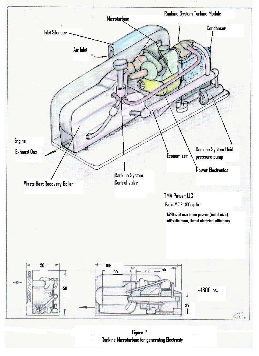
6 To date all tests, start, run and shutdown have been accomplished / controlled by the human factor (manual). An electronic fuel control has not been integrated at this time. proposed Rankine-Microturbine 142 Kw powerplant. RANKINE-MICROTURBINE The Rankine-Microturbine, introduced in this technical paper, represents a second phase program that will build on the two-spool-microturbine core engine once developed. The Rankine-Microturbine unit is estimated to provide a 142Kw electrical power plant at an electrical output efficiency of 40%. The rankine cycle analysis used a binary fluid of ammonia and water selected based on excellent heat transfer properties. Critical, in the study accomplished, is the ability to attain high enthalpy values for entry on the cold side of the economizer. This is a first cut and additional work is needed for this binary fluid evaluation along with other fluids currently used in the industry. The estimated cycle state points for the proposed Rankine Microturbine are shown in figure 6, along with assumptions. Engineering to be accomplished for this product will be the rankine turbine stage (ref. table 2 for a first cut), waste heat recovery boiler, economizer, condenser, control system & valves (with modulation control) to regulate the fluid / vapor flow. The Rankine-Microturbine Power Plant is a combined cycle engine with the exception the rankine turbine stage will be integral to the gas turbine rotor assembly and drive a common Permanent Magnet Alternator, reference figure 5. The new 142 Kw alternator will be scaled from the 78 Kw alternator assembly. Reference figure 7 for the RANKINE TURBINE Figure 5 Rankine-Microturbine Engine The rankine turbine, illustrated in figure 5, is a radial inflow back to back type. Though other types of turbines could be used, the radial was selected for its ruggedness, capability to have 4:1 pressure drop, and thrust balance to minimize the thrust reaction on the gas turbine rotor assembly when used. As the rankine turbine stage comes on line it is anticipated to occur at low rotor speed to minimize effect of mass flow droplets that could damage the blades. Damage would occur due to the baseball effect (i.e blade velocity is greater than the mass flow droplets). Estimated cycle state points, total power and system efficiency are shown in figure 6. Reference table 2 for preliminary turbine stage design. WASTE HEAT RECOVERY BOILER The waste heat recovery boiler will make use of existing type technology typical in the industry and customized for this application. At the design power point, waste heat from the gas turbine exhaust will be at 1050 F, with mass flow of 1.3 lb/sec., and the rankine cycle mass flow of 0.51 lb/sec. The superheated mass flow to the rankine turbine stage is estimated to be 740F. The Rankine Microturbine, superheater source could be other than or supplemental to the gas turbine exhaust gas waste heat, 6
7 through other external heat sources. Also, as a means to start the brayton cycle other than aforementioned air impingement, stored or external heat source could be used or the rankine cycle to drive the brayton cycle start rotation into self sustaining rotor speed requirement. ECONOMIZER Certainly one of the key components for the success of the Rankine-Microturbine is the economizer. This unit will optimize the ability to recover energy not extracted by the rankine turbine. The economizer capability to process the energy latent vapor mass flow, instead of a large loss through the condenser, allows for an increased mass flow (lbs/sec) hence more power extraction through the rankine turbine over a system without an economizer. This is key to the estimated system efficiency. The greater the enthalpy of the mass flow prior to entry into the waste heat recovery boiler the more mass flow that can be processed for the same waste heat from the gas turbine exhaust. Reference figure 6 for cycle state points. In the analysis / design process consideration will also be made for the low temperature side that will take fluid at an estimated temperature of 190 F. The 190F fluid will go from single phase at entry than thru two phase boiling prior to exit of the economizer. Likewise, superheated vapor from the turbine exducer will go through a phase change of superheated to saturated stage prior to exit and entry to the condenser. Operation of the economizer will have several different two-phase heat-transfer phenomena, all of which must be taken into account. DISCUSSION The novel Rankine-Microturbine Power Plant, described in this paper, offers the ability to produce electrical power with low emissions and higher cycle efficiency than current fossil fueled power plants. The ability to provide an electric power plant on a smaller scale than current electric power plants will allow for improved Distributed Energy (D.E.) without necessarily having any line ties. This system will provide the owner / customer the ability to generate reduced cost electrical power with fuel use, heat energy source, diversity. TABLE 2 RANKINE-MICROTURBINE OUT-PUT POWER & PRELIMINARY WHEEL DESIGN Rotor Speed Tip Diameter Mass Flow 104,000 rpm 4.8 inch 0.40 lbm/sec Stage Efficiency 83 % Inlet Turbine Stage Pressure: 1753 psia Inlet Turbine Stage Temperature: 740 F Cp (in) 0.76 BTU/lb-R CONDENSER / PUMP / FAN k 1.37 The condenser will take the mass flow from the economizer hot side and change it to liquid, to be able Inlet Enthalpy H 1147 BTU/lb pump back to economizer low temperature side. The media to be used for cooling will be air flow and is estimated to require a 1.0 kw fan motor. This is debited as Exit Turbine Stage Pressure: 438 psia accessory power, from the microturbine power available Exit Turbine Stage Temperature: 426 F shown in table 1 and listed in table 2. The use of air will minimize fowling of the condenser cold side. It is Exit Enthalpy 988 BTU/lb anticipated to use existing technologies in the industry but unique for this application. The pump for use will be a Rankine Turbine Power 67 kw piston type. The power to drive the electric pump motor is estimated to be 3 kw. This also is debited as accessory Power to drive pump motor * 3 kw power from the microturbine. Power to drive motor fan * 1 kw (* Power from simple cycle gas turbine output balance) 7
8 Figure 6 Rankine Cycle State Points 8
9 9
RANKINE -MICROTURBINE POWER PLANT
 RANKINE -MICROTURBINE POWER PLANT Jon W. Teets, TMA Power, LLC, tmapower@cox.net J. Michael Teets, TMA Power, LLC, tmapower@bellsouth.net ABSTRACT A Rankine-Microturbine Power Plant is a combined cycle
Catalytic Combustor for Ultra-Low NOx Advanced Industrial Gas Turbines
 Catalytic Combustor for Ultra-Low NOx Advanced Industrial Gas Turbines March 12-14, 2002 Microturbine & Industrial Gas Turbines Peer Review Meeting Fairfax, VA Solicitation No:DE-SC02-00CH11000 Dr. Shahrokh
ADVANTAGES OF GTE s Weight reduction of 70% Simplicity Reduced manning requirements Quicker response time Faster Acceleration/deceleration Modular rep
 USES OF GAS TURBINE ENGINES Aircraft Engines Main Propulsion Arleigh Burke, Tichonderoga, Spruance, Oliver Hazard Perry LCACS, Pegasus Auxiliary Applications Electric generators ADVANTAGES OF GTE s Weight
Fuels, Combustion and Environmental Considerations in Industrial Gas Turbines - Introduction and Overview
 Brian M Igoe & Michael J Welch Fuels, Combustion and Environmental Considerations in Industrial Gas Turbines - Introduction and Overview Restricted Siemens AG 20XX All rights reserved. siemens.com/answers
Powertrain Efficiency Technologies. Turbochargers
 Powertrain Efficiency Technologies Turbochargers Turbochargers increasingly are being used by automakers to make it possible to use downsized gasoline engines that consume less fuel but still deliver the
ME3264: LAB 9 Gas Turbine Power System
 OBJECTIVE ME3264: LAB 9 Gas Turbine Power System Professor Chih-Jen Sung Spring 2013 A fully integrated jet propulsion system will be used for the study of thermodynamic and operating principles of gas
WET COMPRESSION. What it Is Not. What it Is. Is not traditional inlet air cooling, like a fogger or a chiller
 IGTI 2011 June 8 th, 2011 What it Is 8 to 25% (~12% 7EA) Power Augmentation at any wet bulb temperature above 45 F Complimentary Technology -used in series w/ inlet cooling & other GT upgrades Technology
Technologies to Reduce GT Emissions
 GE Power Systems Technologies to Reduce GT Emissions Rich Rapagnani Global Marketing & Development March 18, 2003 GE Power Systems Technologies to Reduce GT Emissions Dry Low NOx Combustion Systems Advanced
Siemens SGT6-5000F Gas Turbine Technology Update
 Siemens SGT6-5000F Gas Turbine Technology Update POWER-GEN International Abstract This presentation will update the industry on the latest developments of Siemens SGT6-5000F gas turbine. Since its introduction
Company. Product embodiments. Supersonic stationary air & gas compressors High velocity combustor Supersonic expander
 Company Privately-held R&D company founded in 1992 Focused on unique applications of proven supersonic aircraft technology Primary technology innovations Supersonic stationary air & gas compressors High
Numerical Simulation on the Pattern Factor of the Annular Combustor
 Numerical Simulation on the Pattern Factor of the Annular Combustor Balakrishnan B.M 1, Mohana Priya G 2, Revathi M 3 Department of Mechanical Engineering, Mahendra Engineering College, Salem, India 1
A combustor design applied to the micro turbine. Taichung, Taiwan;
 A combustor design applied to the micro turbine Chuan-Sheng Chen 1, Tzu-Erh Chen 1*, Hong-Chia Hong 1 1 Chung-Shan Institute of Science and Technology, Aeronautical Systems Research Division, Taichung,
Combustion Equipment. Combustion equipment for. Solid fuels Liquid fuels Gaseous fuels
 Combustion Equipment Combustion equipment for Solid fuels Liquid fuels Gaseous fuels Combustion equipment Each fuel type has relative advantages and disadvantages. The same is true with regard to firing
LMS100 Gas Turbine System
 GE Energy LMS100 Gas Turbine System A flexible growth platform to meet changing energy needs. The LMS100 game changing technology from frame and aero gas turbines LMS100 CFM TECH56 CAPPs Combustor LM6000
Diesel Power Generating Plants. Introduction
 Diesel Power Generating Plants Introduction Steve Mackay Dean of Engineering Worked for 30 years in Industrial Automation 30 years experience in mining, oil and gas, electrical and manufacturing industries
Al- Ameen Engg. College. Fluid Machines. Prepared by: AREEF A AP/ ME AL AMEEN ENGINEERING COLLEGE Shoranur.
 Fluid Machines Prepared by: AREEF A AP/ ME AL AMEEN ENGINEERING COLLEGE Shoranur Classification of hydraulic machines HYDROULIC MACHINES (I) Hydraulic Turbines A hydraulic machine which converts hydraulic
CHAPTER 1. Introduction and Literature Review
 CHAPTER 1 Introduction and Literature Review 1.1 Introduction The Active Magnetic Bearing (AMB) is a device that uses electromagnetic forces to support a rotor without mechanical contact. The AMB offers
Development of the Micro Combustor
 Development of the Micro Combustor TAKAHASHI Katsuyoshi : Advanced Technology Department, Research & Engineering Division, Aero-Engine & Space Operations KATO Soichiro : Doctor of Engineering, Heat & Fluid
TYPE CERTIFICATE DATA SHEET
 TYPE CERTIFICATE DATA SHEET No. IM.E.096 for PW800 Series Engines Type Certificate Holder 1000 Marie Victorin Longueuil, Quebec J4G1A1 Canada For : TE.CERT.00052 001 European Aviation Safety Agency, 2016.
Effect of Compressor Inlet Temperature on Cycle Performance for a Supercritical Carbon Dioxide Brayton Cycle
 The 6th International Supercritical CO2 Power Cycles Symposium March 27-29, 2018, Pittsburgh, Pennsylvania Effect of Compressor Inlet Temperature on Cycle Performance for a Supercritical Carbon Dioxide
INTERNAL COMBUSTION ENGINE (SKMM 4413)
") INTERNAL COMBUSTION ENGINE (SKMM 4413) Dr. Mohd Farid bin Muhamad Said Room : Block P21, Level 1, Automotive Development Centre (ADC) Tel : 07-5535449 Email: mfarid@fkm.utm.my HISTORY OF ICE History of
INTERNAL COMBUSTION ENGINE (SKMM 4413) Dr. Mohd Farid bin Muhamad Said Room : Block P21, Level 1, Automotive Development Centre (ADC) Tel : 07-5535449 Email: mfarid@fkm.utm.my HISTORY OF ICE History of
YARWAY NARVIK MODEL 88 SPID SMALL PIPE INLINE DESUPERHEATER
 A wide range of desuperheaters, pneumatic actuators, strainers to satisfy all specifications of the power, pulp and paper industry and process gas applications FEATURES Fabricated construction Special
Product Specification
 Capstone Capstone Turbine Corporation 21211 Nordhoff Street Chatsworth CA 91311 USA Telephone: (818) 734-5300 Facsimile: (818) 734-5320 Website: www.microturbine.com Product Specification Technical Specifications
Design and Fabrication of Simple Turbo Alternator
 Design and Fabrication of Simple Turbo Alternator S.Arunkumar, A.Sridhar, S.Praveen vaitheeswaran, S.Sasikumar, Sefin Jose Department of mechanical engineering, Nandha College of technology, Erode. Abstract
Ignition Reliability in SGT-750 for Gas Blends at Arctic Conditions. Magnus Persson Combustion Expert / Distributed Generation / Sweden
 Ignition Reliability in SGT-750 for Gas Blends at Arctic Conditions Magnus Persson Combustion Expert / Distributed Generation / Sweden siemens.com/power-gas Table of content Objectives of the Project SGT-750
C C A. Combustion Components Associates, Inc.
 C C A Combustion Components Associates, Inc. www.cca-inc.net About CCA CCA is a global provider of combustion control technologies to reduce NOx, particulate matter (PM), unburned carbon and CO emissions
Lecture 27: Principles of Burner Design
 Lecture 27: Principles of Burner Design Contents: How does combustion occur? What is a burner? Mixing of air and gaseous fuel Characteristic features of jet Behavior of free (unconfined) and confined jet
GE s LM2500+G4 Aeroderivative Gas Turbine for Marine and Industrial Applications
 GE Energy GE s LM2500+G4 Aeroderivative Gas Turbine for Marine and Industrial Applications Authored by: Gilbert H. Badeer LM TM Product Marketing Leader Industrial AeroDerivative Gas Turbines imagination
Chapter 9 GAS POWER CYCLES
 Thermodynamics: An Engineering Approach Seventh Edition in SI Units Yunus A. Cengel, Michael A. Boles McGraw-Hill, 2011 Chapter 9 GAS POWER CYCLES Mehmet Kanoglu University of Gaziantep Copyright The McGraw-Hill
Technology Application to MHPS Large Frame F series Gas Turbine
 11 Technology Application to MHPS Large Frame F series Gas Turbine JUNICHIRO MASADA *1 MASANORI YURI *2 TOSHISHIGE AI *2 KAZUMASA TAKATA *3 TATSUYA IWASAKI *4 The development of gas turbines, which Mitsubishi
Numerical simulation of detonation inception in Hydrogen / air mixtures
 Numerical simulation of detonation inception in Hydrogen / air mixtures Ionut PORUMBEL COMOTI Non CO2 Technology Workshop, Berlin, Germany, 08.03.2017 09.03.2017 Introduction Objective: Development of
Texas Technology Showcase March 2003 Houston, TX
 Texas Technology Showcase 17-19 March 2003 Houston, TX Overview Who Is Kawasaki Gas Turbines? What Causes NOx? How Can We Control NOx? Field Results Summary Kawasaki Gas Turbine History 1943 Built First
Bombardier Challenger Auxiliary Power Unit
 GENERAL A Honeywell 36 150(CL) constant-speed gas turbine auxiliary power unit (APU) is installed within a fire-resistant compartment in the aft equipment bay. The APU drives a generator, providing AC
Chempump. G Series. Canned Motor Pumps
 Chempump G Series Canned Motor Pumps G SERIES Exceptional Fugitive Emissions Containment Chempump introduced the first hermetically sealed pump and motor design over 50 years ago, and we ve been improving
TCDS NUMBER E00078NE U.S. DEPARTMENT OF TRANSPORTATION REVISION: 3 DATE: April 12, 2011
 TCDS NUMBER E00078NE U.S. DEPARTMENT OF TRANSPORTATION REVISION: 3 DATE: April 12, 2011 FEDERAL AVIATION ADMINISTRATION GENERAL ELECTRIC COMPANY MODELS: TYPE CERTIFICATE DATA SHEET E00078NE GEnx-1B54 GEnx-1B58
Paper No: 05-IAGT-1.1 INDUSTRIAL APPLICATION OF GAS TURBINES COMMITTEE
 Paper No: 05-IAGT-1.1 INDUSTRIAL APPLICATION OF GAS TURBINES COMMITTEE Mercury 50 Field Evaluation and Product Introduction by David Teraji of Solar Turbines Incorporated San Diego, California, USA 1 AUTHORS
Training Title GAS TURBINE AND COMPRESSOR OPERATION, MAINTENANCE AND TROUBLESHOOTING
 Training Title GAS TURBINE AND COMPRESSOR OPERATION, MAINTENANCE AND TROUBLESHOOTING Training Duration 5 days Training Venue and Dates Gas Turbine and Compressor Operation, Maintenance and Troubleshooting
Chapter 9 GAS POWER CYCLES
 Thermodynamics: An Engineering Approach, 6 th Edition Yunus A. Cengel, Michael A. Boles McGraw-Hill, 2008 Chapter 9 GAS POWER CYCLES Copyright The McGraw-Hill Companies, Inc. Permission required for reproduction
Component and System Level Modeling of a Two-Phase Cryogenic Propulsion System for Aerospace Applications
 Component and System Level Modeling of a Two-Phase Cryogenic Propulsion System for Aerospace Applications J. LoRusso, B. Kalina, M. Van Benschoten, Roush Industries GT Users Conference November 9, 2015
FLAME COOLING AND RESIDENCE TIME EFFECT ON NO x AND CO EMISSION IN A GAS TURBINE COMBUSTOR
 FLAME COOLING AND RESIDENCE TIME EFFECT ON NO x AND CO EMISSION IN A GAS TURBINE COMBUSTOR MOHAMED S. T. ZAWIA Engineering College Tajoura Mech. Eng. Dept. El-Fateh University P.O Box 30797 Libya E-mail
Propeller Blade Bearings for Aircraft Open Rotor Engine
 NTN TECHNICAL REVIEW No.84(2016) [ New Product ] Guillaume LEFORT* The Propeller Blade Bearings for Open Rotor Engine SAGE2 were developed by NTN-SNR in the frame of the Clean Sky aerospace programme.
Content : 4.1 Brayton cycle-p.v. diagram and thermal efficiency. 4Marks Classification of gas turbines.
 Content : 4.1 Brayton cycle-p.v. diagram and thermal efficiency. 4Marks Classification of gas turbines. 4.2 Construction and working of gas turbines i) Open cycle ii) Closed cycle gas Turbines, P.V. and
Planes, Trains and Stationary Power
 Planes, Trains and Stationary Power Outline Product Portfolio Thermodynamic Cycles (Gas Turbine, Diesel, Natural Gas) Fuels Perspective / Renewables Outline Product Portfolio Thermodynamic Cycles (Gas
GENERAL The Honeywell model TFE731-40AR turbofan engine is a lightweight, two-spool, geared-stage, front-fan, jet engine.
 ENGINE GENERAL The Honeywell model TFE731-40AR turbofan engine is a lightweight, two-spool, geared-stage, front-fan, jet engine. The cross section of the engine is shown in Figure 7-71-1, page VII-71-3.
TurboGen TM Gas Turbine Electrical Generation System Sample Lab Experiment Procedure
 TurboGen TM Gas Turbine Electrical Generation System Sample Lab Experiment Procedure Lab Session #1: System Overview and Operation Purpose: To gain an understanding of the TurboGen TM Gas Turbine Electrical
Gas Power Cycles. Tarawneh
 Gas Power Cycles Dr.Mohammad Tarawneh ) Carnot cycle 2) Otto cycle ) Diesel cycle - Today 4) Dual Cycle 5) Stirling cycle 6) Ericsson cycles 7) Brayton cycle Carnot Cycle Reversible isothermal expansion
HIGH VELOCITY THERMAL GUN FOR SURFACE PREPARATION AND TREATMENT. I.A. Gorlach
 HIGH VELOCITY THERMAL GUN FOR SURFACE PREPARATION AND TREATMENT I.A. Gorlach Department of Industrial Engineering School of Process and Mechanical Engineering Technikon Witwatersrand Johannesburg, South
Homogeneous Charge Compression Ignition (HCCI) Engines
 Engines") Homogeneous Charge Compression Ignition (HCCI) Engines Aravind. I. Garagad. Shri Dharmasthala Manjunatheshwara College of Engineering and Technology, Dharwad, Karnataka, India. ABSTRACT Large reductions
Homogeneous Charge Compression Ignition (HCCI) Engines Aravind. I. Garagad. Shri Dharmasthala Manjunatheshwara College of Engineering and Technology, Dharwad, Karnataka, India. ABSTRACT Large reductions
APPLICATION OF STAR-CCM+ TO TURBOCHARGER MODELING AT BORGWARNER TURBO SYSTEMS
 APPLICATION OF STAR-CCM+ TO TURBOCHARGER MODELING AT BORGWARNER TURBO SYSTEMS BorgWarner: David Grabowska 9th November 2010 CD-adapco: Dean Palfreyman Bob Reynolds Introduction This presentation will focus
Recovering Wasted Heat. Double Arrow Engineering
 Recovering Wasted Heat Double Arrow Engineering Background of Problem Internal Combustion Engine Efficiency The average gasoline engine is 30-35% efficient: 30-35% of the energy stored in the gasoline
The Aircraft Engine Design Project Fundamentals of Engine Cycles
 GE Aviation The Aircraft Engine Design Project Fundamentals of Engine Cycles 1 Spring 2008 Peter Rock Earl Will DeShazer Ken Gould GE Aviation Technical History I-A - First U.S. jet engine (Developed in
SUPERCHARGER AND TURBOCHARGER
 SUPERCHARGER AND TURBOCHARGER 1 Turbocharger and supercharger 2 To increase the output of any engine more fuel can be burned and make bigger explosion in every cycle. i. One way to add power is to build
Engine Performance Analysis
 Engine Performance Analysis Introduction The basics of engine performance analysis The parameters and tools used in engine performance analysis Introduction Parametric cycle analysis: Independently selected
Emission from gasoline powered vehicles are classified as 1. Exhaust emission 2. Crank case emission 3. Evaporative emission. Table 1.
 Introduction: Main three types of automotive vehicle being used 1. Passenger cars powered by four stroke gasoline engines 2. Motor cycles, scooters and auto rickshaws powered mostly by small two stroke
ELECTRIC POWER RESEARCH INSITUTE (EPRI) 2011 CONDENSER TECHNOLOGY CONFERENCE AUGUST 3-4, 2011, CHICAGO, ILLINOIS
 2011 CONDENSER TECHNOLOGY CONFERENCE AUGUST 3-4, 2011, CHICAGO, ILLINOIS") ELECTRIC POWER RESEARCH INSITUTE (EPRI) 2011 CONDENSER TECHNOLOGY CONFERENCE AUGUST 3-4, 2011, CHICAGO, ILLINOIS IMPORTANCE OF TEMPERATURE OF BYPASS STEAM ADMITTED INTO A STEAM SURFACE CONDENSER IN A COMBINED
ELECTRIC POWER RESEARCH INSITUTE (EPRI) 2011 CONDENSER TECHNOLOGY CONFERENCE AUGUST 3-4, 2011, CHICAGO, ILLINOIS IMPORTANCE OF TEMPERATURE OF BYPASS STEAM ADMITTED INTO A STEAM SURFACE CONDENSER IN A COMBINED
VAD Variable Area Desuperheaters
 Local regulations may restrict the use of this product to below the conditions quoted. In the interests of development and improvement of the product, we reserve the right to change the specification without
USOO A United States Patent (19) 11 Patent Number: 6,125,814 Tang (45) Date of Patent: Oct. 3, 2000
 11 Patent Number: 6,125,814 Tang (45) Date of Patent: Oct. 3, 2000") USOO6125814A United States Patent (19) 11 Patent Number: Tang (45) Date of Patent: Oct. 3, 2000 54) ROTARY WANE ENGINE FOREIGN PATENT DOCUMENTS 101.1256 5/1977 Canada... 123/222 76 Inventor: Heian d t
USOO6125814A United States Patent (19) 11 Patent Number: Tang (45) Date of Patent: Oct. 3, 2000 54) ROTARY WANE ENGINE FOREIGN PATENT DOCUMENTS 101.1256 5/1977 Canada... 123/222 76 Inventor: Heian d t
CAT PAU 99(2) SUPERSEDES CAT.NO SARAVEL PACKAGED AIR CONDITIONING UNITS
 SUPERSEDES CAT.NO SARAVEL PACKAGED AIR CONDITIONING UNITS") CAT PAU 99(2) SUPERSEDES CAT.NO.200-95 SARAVEL PACKAGED AIR CONDITIONING UNITS TABLE OF CONTENTS Introduction...3 Physical Data..... 4 Selection Procedure....5-7 Water Cooled Packaged Unit Ratings....
CAT PAU 99(2) SUPERSEDES CAT.NO.200-95 SARAVEL PACKAGED AIR CONDITIONING UNITS TABLE OF CONTENTS Introduction...3 Physical Data..... 4 Selection Procedure....5-7 Water Cooled Packaged Unit Ratings....
CFD Simulation of Dry Low Nox Turbogas Combustion System
 CFD Simulation of Dry Low Nox Turbogas Combustion System L. Bucchieri - Engin Soft F. Turrini - Fiat Avio CFX Users Conference - Friedrichshafen June 1999 1 Objectives Develop a CFD model for turbogas
European Aviation Safety Agency
 European Aviation Safety Agency EASA TYPE-CERTIFICATE DATA SHEET Number : IM.E.016 Issue : 07 Date : 21 May 2014 Type : Williams International Co. FJ44 Series Engines s FJ44-1A FJ44-1AP FJ44-2A FJ44-2C
Magnetic Bearings for Supercritical CO2 Turbomachinery
 The 6 th International Supercritical CO 2 Power Cycles Symposium March 27-29, 2018, Pittsburgh, Pennsylvania Magnetic Bearings for Supercritical CO2 Turbomachinery Richard Shultz Chief Engineer Waukesha
A Practical Guide to Free Energy Devices
 A Practical Guide to Free Energy Devices Part PatD20: Last updated: 26th September 2006 Author: Patrick J. Kelly This patent covers a device which is claimed to have a greater output power than the input
Applications. Compressor-Features The Vilter Advantages. LNG Boil Off Gas Gathering BIO - Gas Digester CO 2 Nitrogen Hydrogen Refrigerant
 Parallex TM Slide System - It s the key to part load efficiencies far superior to twin screw compressors. Capacity and volume slides move independently of each other based on load, eliminating over or
KINGS COLLEGE OF ENGINEERING DEPARTMENT OF MECHANICAL ENGINEERING. Question Bank. UNIT-I THERMODYNAMIC CYCLES Part-A (2 Marks)
") KINGS COLLEGE OF ENGINEERING DEPARTMENT OF MECHANICAL ENGINEERING Question Bank Sub. Code/Name: ME1351 - THERMAL ENGINEERING Year/Sem: III/VI 1. What is a thermodynamic cycle? UNIT-I THERMODYNAMIC CYCLES
KINGS COLLEGE OF ENGINEERING DEPARTMENT OF MECHANICAL ENGINEERING Question Bank Sub. Code/Name: ME1351 - THERMAL ENGINEERING Year/Sem: III/VI 1. What is a thermodynamic cycle? UNIT-I THERMODYNAMIC CYCLES
November 8, 2018 GAS TURBINE ENGINE SECONDARY FLOW SYSTEMS
 November 8, 2018 GAS TURBINE ENGINE SECONDARY FLOW SYSTEMS Agenda 1 What is Secondary Flow? Purpose for the Secondary Flow Systems Chargeable Vs Nonchargeable Flows Seals Selection and Leakage Effects
Effects of Dilution Flow Balance and Double-wall Liner on NOx Emission in Aircraft Gas Turbine Engine Combustors
 Effects of Dilution Flow Balance and Double-wall Liner on NOx Emission in Aircraft Gas Turbine Engine Combustors 9 HIDEKI MORIAI *1 Environmental regulations on aircraft, including NOx emissions, have
LANDFILL GAS ELEVATED (CANDLESTICK) FLARE SYSTEM
 FLARE SYSTEM") LANDFILL GAS ELEVATED (CANDLESTICK) FLARE SYSTEM Part 1. General 1.01 Description A. This section describes a candlestick flare system for the combustion of landfill gases. The flare system must be of
LANDFILL GAS ELEVATED (CANDLESTICK) FLARE SYSTEM Part 1. General 1.01 Description A. This section describes a candlestick flare system for the combustion of landfill gases. The flare system must be of
A Session 2004 CIGRÉ
 21, rue d'artois, F-78 Paris http://www.cigre.org A1-16 Session 24 CIGRÉ The World s Largest Capacity Turbine Generators with Indirect Hydrogen-Cooling Toshio Kitajima*, Hiromichi Ito, Susumu Nagano, Yukihiko
The Pratt & Whitney TALON X Low Emissions Combustor: Revolutionary Results with Evolutionary Technology
 45th AIAA Aerospace Sciences Meeting and Exhibit 8-11 January 2007, Reno, Nevada AIAA 2007-386 The Pratt & Whitney TALON X Low Emissions Combustor: Revolutionary Results with Evolutionary Technology Randal
THE EFFECT OF BLADE LEAN ON AN AXIAL TURBINE STATOR FLOW HAVING VARIOUS HUB TIP RATIOS. Dr. Edward M Bennett
 THE EFFECT OF BLADE LEAN ON AN AXIAL TURBINE STATOR FLOW HAVING VARIOUS HUB TIP RATIOS Dr. Edward M Bennett ABSTRACT The effect of simple lean on an axial turbine stator was examined using a threedimensional
Agenda Velocys Introduction Modular FT Technology Conventional FT Technology FT Demonstration Status Modular Hydrocracking Technology
 Modular, Compact Fischer-Tropsch Technology 13 October, 2008 Jeff S. McDaniel 1 Agenda Velocys Introduction Modular FT Technology Conventional FT Technology FT Demonstration Status Modular Hydrocracking
REVERSE TURBO BRAYTON CYCLE CRYOCOOLER DEVELOPMENT FOR LIQUID HYDROGEN SYSTEMS
 REVERSE TURBO BRAYTON CYCLE CRYOCOOLER DEVELOPMENT FOR LIQUID HYDROGEN SYSTEMS PI: L. Chow (University of Central Florida) J. Kapat (University of Central Florida) T. Wu (University of Central Florida)
EFFECT OF INJECTION ORIENTATION ON EXHAUST EMISSIONS IN A DI DIESEL ENGINE: THROUGH CFD SIMULATION
 EFFECT OF INJECTION ORIENTATION ON EXHAUST EMISSIONS IN A DI DIESEL ENGINE: THROUGH CFD SIMULATION *P. Manoj Kumar 1, V. Pandurangadu 2, V.V. Pratibha Bharathi 3 and V.V. Naga Deepthi 4 1 Department of
Steam Turbines and Gas Expanders. Reliability, Efficiency, Performance
 Steam Turbines and Gas Expanders Reliability, Efficiency, Performance Introduction Proven Reliability and Efficiency Dependable, versatile turbomachinery is essential for today s refinery, chemical process,
Thermal Unit Operation (ChEg3113)
") Thermal Unit Operation (ChEg3113) Lecture 5- Heat Exchanger Design Instructor: Mr. Tedla Yeshitila (M.Sc.) Today Review Heat exchanger design vs rating of heat exchanger Heat exchanger general design procedure
Thermal Unit Operation (ChEg3113) Lecture 5- Heat Exchanger Design Instructor: Mr. Tedla Yeshitila (M.Sc.) Today Review Heat exchanger design vs rating of heat exchanger Heat exchanger general design procedure
quincy qsg series QuincyCompressor.com Made in the U.S.A. Performance You Demand. Reliability You Trust. options & Accessories Applications
 QUINCY qsg SERIES rotary screw gas compressor quincy qrng series reciprocating gas compressor natural gas compressors quincy qsg series rotary screw gas compressor durable design Quincy QSG rotary gas
Application Information
 Moog Components Group manufactures a comprehensive line of brush-type and brushless motors, as well as brushless controllers. The purpose of this document is to provide a guide for the selection and application
17-IAGT-104 Siemens introduces the SGT-A45 mobile unit: superior performance with trusted technology
 17-IAGT-104 Siemens introduces the SGT-A45 mobile unit: superior performance with trusted technology By Cristiano Balestrino, Steve Lewis Siemens Power & Gas Presented at the 2017 Symposium on Industrial
Product Specification
 Phone: (818) 734-5300 Fax: (818) 734-5320 Web: www.capstoneturbine.com Product Specification Model C65 Capstone MicroTurbine 460044 Rev D (May 2013) Page 1 of 15 Capstone Turbine Corporation 21211 Nordhoff
GF CALORPLAST Heat Exchangers day lead time on catalog products
 GF LORPLST Heat Exchangers 7 10 day lead time on catalog products Plating and Metal Surface Finishing hemical Processing In the Plating and Metal Surface Finishing industries in particular, heating and
Pressurized Air Cooled Generators
 PGI Orlando Dec. 13, 2016 Pressurized Air Cooled Generators Mike Zborovsky New App Generator Portfolio Owner siemens.com Pressurized Air-Cooled Generator (SGenX-2000P) Table of content Introduction 3 Portfolio
Advanced gas turbine power cycles
 Advanced gas turbine power cycles Chris Hodrien INLET FUEL INLET COMPRESSOR COMBUSTORS POWER TURBINE EXHAUST Typical aero-derivative GE LM6000, 40 MW Heavy-duty GT (GE9H) 370 tonnes GT design convergence
Fundamentals of steam turbine systems
 Principles of operation Fundamentals of steam turbine systems - The motive power in a steam turbine is obtained by the rate of change in momentum of a high velocity jet of steam impinging on a curved blade
Hybrid Motor Technology to Achieve Efficiency Levels Beyond NEMA Premium
 Hybrid Motor Technology to Achieve Efficiency Levels Beyond NEMA Premium Richard R. Schaefer, Baldor Electric Company ABSTRACT This paper will discuss the latest advances in AC motor design that combines
Engineering Success by Application of STAR-CCM+ for Modern Gas Turbine Design
 STAR Japanese Conference 2013 December 3, Yokohama, Japan Engineering Success by Application of STAR-CCM+ for Modern Gas Turbine Design Norbert Moritz, Karsten Kusterer, René Braun, Anis Haj Ayed B&B-AGEMA
DEPARTMENT OF TRANSPORTATION FEDERAL AVIATION ADMINISTRATION TYPE CERTIFICATE DATA SHEET NO. 1E8
 DEPARTMENT OF TRANSPORTATION FEDERAL AVIATION ADMINISTRATION 1E8 Revision 18 PRATT & WHITNEY AIRCRAFT TURBO WASP JT3D-1 JT3D-3 JT3D-1A JT3D-3B JT3D-1-MC6 JT3D-3C JT3D-1A-MC6 JT3D-7 JT3D-1-MC7 JT3D-7A JT3D-1A-MC7
Model Dual Function Planetary Gear Reducer
 Model 3210 Dual Function Planetary Gear Reducer I. OVERVIEW The Model 3210 Planetary Gear Reducer is an extremely robust, dual function power transmission device that combines a conventional (in line)
SCR Variable Speed Series Rotary Screw Compressor
 SCR Variable Speed Series Rotary Screw Compressor WESTAIR AIR COMPRESSORS FEATURES INCLUDE 7.5 kw to 280 kw units available Pressure ranging from 7 bar to 12.5 bar High quality Inovance Inverter Large
Electric Drive - Magnetic Suspension Rotorcraft Technologies
 Electric Drive - Suspension Rotorcraft Technologies William Nunnally Chief Scientist SunLase, Inc. Sapulpa, OK 74066-6032 wcn.sunlase@gmail.com ABSTRACT The recent advances in electromagnetic technologies
QUANTUM PARALLEL SHAFT FAN DRIVE by Amarillo Gear Company
 QUANTUM PARALLEL SHAFT FAN DRIVE by Amarillo Gear Company The patented Quantum Parallel Shaft Fan Drive for dry cooling systems reflects a long history of quality workmanship and reliability. Amarillo
TurboGen TM Gas Turbine Electrical Generation System Sample Lab Experiment Procedure
 TurboGen TM Gas Turbine Electrical Generation System Sample Lab Experiment Procedure Lab Session #1: System Overview and Operation Purpose: To gain an understanding of the TurboGen TM Gas Turbine Electrical
Numerical Simulation of Gas Turbine Can Combustor Engine
 Numerical Simulation of Gas Turbine Can Combustor Engine CH UMAMAHESHWAR PRAVEEN 1*, A HEMANTH KUMAR YADAV 2 1. Engineer, CDG BOEING Company, Chennai, India. 2. B.Tech Aeronautical Engineer 2012 passout,
Flexider FLUID CATALYTIC CRACKING UNIT EXPANSION JOINTS INDUSTRIAL. An IMCI Company
 FLUID CATALYTIC CRACKING UNIT EXPANSION JOINTS An IMCI Company CALL TOLL FREE: 1-888-979-FLEX Design and Engineering specializes in the custom design and engineering of FCCU expansion joints. These items
Engine Technology Development to Address Local Air Quality Concerns
 Engine Technology Development to Address Local Air Quality Concerns John Moran Corporate Specialist Combustion Rolls-Royce Associate Fellow - Combustion Overview This presentation summarizes material presented
ME2301 THERMAL ENGINEERING L T P C OBJECTIVE:
 ME2301 THERMAL ENGINEERING L T P C 3 1 0 4 OBJECTIVE: To integrate the concepts, laws and methodologies from the first course in thermo dynamics into analysis of cyclic processes To apply the thermodynamic
5. Combustion of liquid fuels. 5.1 Atomization of fuel
 5. Combustion of liquid fuels 5.1 Atomization of fuel iquid fuels such as gasoline, diesel, fuel oil light, fuel oil heavy or kerosene have to be atomized and well mixed with the combustion air before
Step Motor Lower-Loss Technology An Update
 Step Motor Lower-Loss Technology An Update Yatsuo Sato, Oriental Motor Management Summary The demand for stepping motors with high efficiency and low losses has been increasing right along with the existing
ENHANCED ROTORDYNAMICS FOR HIGH POWER CRYOGENIC TURBINE GENERATORS
 The 9th International Symposium on Transport Phenomena and Dynamics of Rotating Machinery Honolulu, Hawaii, February -1, ENHANCED ROTORDYNAMICS FOR HIGH POWER CRYOGENIC TURBINE GENERATORS Joel V. Madison
DRAG VLN Turbine Bypass Valve for Hot Reheat Bypass Applications
 DRAG VLN Turbine Bypass Valve for Hot Reheat Bypass Applications VLN delivers superior pressure reduction and temperature control in a compact, high capacity steam conditioning control valve. 2 n Proven
Power Generation Services Solutions for challenging Markets
 Power Generation Services Solutions for challenging Markets Philipp Leifeld, GT Service Engineering / Dirk Kampe Marketing GT Modernizations & Upgrades Matthias Migl, Principal Key Expert Overall Plant