USER MANUAL MINI BMS DISTRIBUTED VERSION
|
|
|
- Sophie Lawrence
- 5 years ago
- Views:
Transcription

1 USER MANUAL MINI BMS DISTRIBUTED VERSION
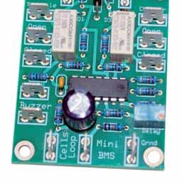
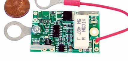
2 MiniBMS is a battery management system designed for LiFePo4 cells, used in Electric Vehicles. MiniBMS is designed to be reliable and cost effective solution; it has most basic functions, implemented via simple analog circuit and one wire interface, which also allows easy installation and troubleshooting. MiniBMS Features: Support for HiPower, ThunderSky, SkyEnergy and other LiFePo4 cells. Installs directly on cell terminals using included ring terminals. One terminal has rigid connection supporting BMS module, the other is connected via short wire. This design allows installation on virtually any cell size. BMS module is very small, 48mm x 30mm and fits easily on most prismatic cells. Optional support for centralized installation, with single board managing up to 16 cells. Useful for smaller cell sizes and packs, such as E-bikes, small cars, etc. You must select this option when ordering your BMS modules, so they will not be cut into individual boards. Low profile Printed Circuit Boards with Surface Mount Components allows installation in tight spaces, inside battery boxes, etc. Components are sealed from dirt and moisture, safe to install under the hood of the car. Single wire Normally Closed (NC) analog communication loop. All modules connect in a single series string using automotive style Quick Disconnect crimp terminals. NC loop is extra reliable since it senses loose wiring connections as well as low and high cell conditions. Analog NC loop is not affected by high electrical noise inside EV, which has severe negative effects on digital communications. Less than 10 ma operating current to prevent bleeding cells over long time period when not in daily use. Resistors protect every part of the circuit from potential semiconductor failures. Any component failure results in BMS alerts, protecting the battery even from BMS itself. PTC resettable fuse protects from overheating during shunting as well as short circuit conditions. Fuse opens if temp reaches 80C or if shunting current reaches 1 Amp. Open fuse results in same alert as full charge, shutting down the charger. Fuse returns to normal conditions automatically. High Voltage Cutoff (HVC). HVC voltage level is selectable at the time of purchase for most popular cell types. When first cell reaches HVC it will cause BMS to shut down the charger, effectively protecting your battery pack. Since BMS can control AC power to the charger, you can use practically any charger with this BMS, even dumb chargers without special LiFePo4 charging profiles. This requires purchase of high current solid state AC relay, not included with BMS. If your charger has BMS shutoff input, then you don t need AC relay. This datasheet is an example of such AC relay sh.pdf. You can find many others from various online electronic parts retailers, including Ebay. Make sure you get a relay rated for higher continuous currents than your charger pulls from AC outlet, so it doesn t get too hot. Still, you may need to mount it on a heat sink if it gets hot. Low Voltage Cutoff (LVC) is temperature compensated. Each module has a thermistor which automatically adjusts LVC for each cell, which works well if some cells are installed in different locations in the car with different temperatures at each location. LVC is set to 2.5V at 0C temp, 2.6V at 25C temp and 2.7V at 50C temp, linearly adjusting itself across the entire temp range. Green LED on each cell module indicates normal conditions, i.e. cell voltage is between LVC and HVC levels. All cells must have Green LEDs on during normal use. When any cell goes below LVC or above HVC levels, Green LED turns off and alert is created by open NC loop. Optional shunt balancing has a maximum shunting current of 0.75 Amp. Red LED comes on during shunting for visual indication. Shunting slows down charging process on cells reaching HVC sooner than other cells, allowing other cells to catch up. This is referred to as top balancing. Initial manual balancing is recommended, so BMS can keep the pack balanced long term. Head end control board is an interface between cell modules and charger and motor controller. It uses simple NO/NC connections to act on LVC and HVC events. Control board senses alerts from NC loop and acts on those by reducing the throttle ( LVC ) and shutting down the charger ( HVC ). Simple interface allows compatibility with virtually any charger and motor controller. Head end control board supports piezo Buzzer to provide audible alarm for the driver when alerts are triggered by cell modules. Any 12V low current buzzer from Radio Shack can be used.
3 MiniBMS Installation: CRITICAL WARNING: Make sure your battery pack is physically disconnected from the rest of your EV when attaching BMS modules to your cells. Failure to do so may result in last BMS module completing the high voltage circuit before it gets attached to the last cell terminal. This will damage the BMS module beyond repair and will not be covered by warranty!!! 1. Install cell modules on each cell. You MUST install BMS terminals on top of copper links, but under the flat washer, to make sure it won t be twisted when you torque the terminal bolt. DO NOT install BMS terminals under copper links to avoid passing high currents thru the BMS terminal. Thread both bolts by hand to secure both sides of BMS module before tightening terminal bolts. 2. Using 18AWG 16AWG wire and 0.25 Quick Disconnect crimp terminals fabricate wires to connect all cells in one series string. Leave some slack on each wire to avoid stress if cells shift a little during use. Signal connections are not polarized, so you can connect in any order, as long as wire loop goes thru all cells and both ends meet at the head end control board. WARNING: Push on connectors are very tight. With enough force when pushing connector over the blade terminal you can lift the trace off the PCB and damage the connection. I recommend loosening up the connector a little bit with flat screwdriver before pushing it over the terminal. 3. Wire head end control board according to attached schematics. B+ terminal must come directly from the 12V aux battery to ensure BMS is powered while ignition is off during charging. Ignition input is required to reset BMS after each charge. When wiring to charger and motor controller, please find most appropriate diagram for your type of charger and throttle assembly. If you are not sure which diagram is best for you, contact MiniBMS support and provide models of your charger, controller and throttle assembly to get detailed wiring directions. 4. You can use any 12v low current Buzzer from Radio Shack or other retailers. The more annoying it is the more inclined the driver will be to react on LVC alerts, but it should not be deafening so the driver can pay attention to the road. Buzzer current should not exceed 250 ma, otherwise it will trip the fuse on the control board. Mount the buzzer under the dash board or under the steering wheel, so it can be heard clearly by the driver. 5. To test head end control board after it s been wired, manually disconnect one of NC Loop wires, simulating BMS alert condition. This should result in buzzer coming on after 2-4 second delay. Delay is adjustable via trimpot on the head end control board. Delay is designed to filter out false LVC alerts during brief voltage sags which are normal during hard accelerations. When NC Loop connection is restored, buzzer should turn off immediately. It is not recommended to set delay more than 4 seconds to prevent deep discharge during LVC events. 6. To test charger connection to BMS, after all charger connections are made, turn on the charger and make sure it starts charging the pack normally. Ignition must be off at this time, so BMS can expect HVC signal. Manually break NC Loop by disconnecting one of the wires. After 2-4 second delay charger should turn off. When you restore NC Loop connection charger should remain inoff state until you cycle ignition key on and off. 7. It s a bit more difficult to test BMS connection to motor controller since it requires running motor to observe throttle reduction. If your EV is drivable, you can arrange to interrupt NC wire loop from the cabin, using a temporary switch in line with NC wire loop to simulate LVC event. After 2-4 second delay you should observe throttle reduction and buzzer alert. In real LVC event throttle reduction will prolong your battery life so you can get off the road safely and prevent damage to your battery pack.
4 MiniBMS Operation: 1. During charging Ignition key is off, which tells BMS to expect HVC event. When first cell reaches HVC voltage BMS will interrupt NC loop and cause charger AC relay to interrupt power to the charger. HVC event will latch on, so charger will not come back on when resting voltage goes below HVC. 1. During charging Ignition key is off, which tells BMS to expect HVC event. When first cell reaches HVC voltage BMS will interrupt NC loop and cause charger AC relay to interrupt power to the charger. HVC event will latch on, so charger will not come back on when resting voltage goes below HVC. NOTE: In ideal world HVC function may not even interfere with the charger, allowing it to finish CC/CV charging phases as intended by charger s manufacturer. However, in case there enough misbalance across multiple cells such that one cell gets to HVC much sooner than others, HVC will protect the cell by cutting off charging process prematurely. It is up to you what action to take depending on how prematurely HVC cutoff occurs. If charger is interrupted only a few minutes before the end of CV phase, at which point charging current is very low, then you are not losing much and you can simply let this happen every day. If you have BMS with shunting option, then shunting process will over time pull back this pesky cell and equalize it with others. Or, you can manually attempt to discharge that cell a little bit, to bring it down in line with others. You have many choices and MiniBMS is here to protect your battery investment, even at the cost of somewhat incomplete charge. You may soon realize that small amounts of charge at the end of the charge cycle are not all that important and not worth risking overcharge of individual cell. 2. You must disconnect the charger before turning Ignition on. Once ignition key is on, BMS will reset HVC circuit to prepare it for the next charging cycle. 3. Once Ignition key is on BMS expects LVC events. During driving when your pack gets close to low charge levels BMS will sense LVC events from cells with smallest capacity. This will initially happen during heavy acceleration due to deeper voltage sag. 2-4 second delay is designed to filter out brief voltage sags which may happen while there is still plenty of charge in the pack. However, as you get closer to empty pack, LVC events will become more frequent and prolonged, which is an indication to the driver to get off the road ASAP. If LVC alerts become solid with little or no throttle applied, you have reached the lowest charge level and should not drive anymore. It s possible that one or two cells are damaged or have significantly lower capacity than others, causing LVC alerts when you don t expect them. Check Green LEDs on all BMS modules to find offending cells, which will have Green LED turned off during LVC event. 4. Any lose wiring connections between cells and/or head end control board will also cause LVC/HVC alerts to bring your attention, so you can find offending connection and fix it. 5. In a rare event when LVC alert is on solid you must keep the Ignition key on while turning on the charger. This is necessary to prevent charger relay from false tripping since it can t distinguish LVC event from HVC event. Within few minutes all cells will climb over LVC voltage and you can turn off ignition key and charger will remain running. This situation is an extreme case and should never be experienced unless you ignore LVC alerts and run your pack to empty. DO NOT leave the Ignition key on unattended while charging; it will disable BMS ability to turn off the charger when first cell reaches HVC level.

5 MiniBMS Wiring Diagram: This basic diagram shows how to interface MiniBMS with your battery pack, charger and motor controller. This diagram shows motor controller with 2 wire resistive 0-5K pot box, which is common for Curtis, Logisystems and some other controllers. 5K resistor shown in the diagram will be connected in parallel to the pot box during LVC event, which will reduce total resistance to 2.5K, which effectively clamps the throttle to 50% of max throttle. You can manipulate resistor value if you wish to clamp LVC throttle to higher or lower levels. Keep in mind that getting off road safely should be higher priority than saving few battery cells, don t clamp the throttle too much so the car can keep driving at lower speeds. Next diagram shows only motor controller portion of MiniBMS wiring diagram for 3 wire resistive pot box and controller which expects 0-5V throttle input. Controllers which use this type of throttle input are Soliton1, Kelly, and others. Check controller s documentation for details. Do not use this diagram with Hall Effect throttles, please refer to the following diagram for Hall Effect throttles. If you are not sure which diagram works best for your conversion, please contact MiniBMS support for assistance

6 Next diagram shows only motor controller portion of MiniBMS wiring diagram for 3 wire Hall Effect throttle. Since Hall Effect device is powered by 5V input, we must use voltage divider on the output side of the throttle to reduce its output level during LVC event.

7 Optional charger controls: Some chargers have BMS input functions, which turn off the charger based on ON/ OFF or specific voltage input. You can wire such charger to MiniBMS control board without using high power solid state AC relay. Please note that control board NO/NC output has 2 Amp commutation current limits, if you exceed it you may damage the relay. Please check with MiniBMS support if you are not sure about this option. See additional diagrams below for optional charger interface. Auxillary 12V battery note: MiniBMS relies on constant power supplied from your 12V aux battery. Please make sure your 12V battery is properly charged at all times to ensure correct BMS operation. For safety reasons MiniBMS will shut off the charging process if it loses 12V power to the head end control board, which may leave you with undercharged pack unexpectedly. MiniBMS takes less than 50 ma from 12V battery, likely less than self discharge rate of typical Lead Acid battery, but any failure of the 12V battery will result in BMS triggering HVC event, so your traction pack will still be protected from potential overcharge, even at the cost of premature charger interruption. LVC safety note: MiniBMS is designed to protect your battery pack from premature damage due to overcharge and over discharge. Specifically LVC function is carefully designed not to interfere with normal driving conditions until there is very little energy left in the pack. You should not let your pack get to LVC alerts on regular basis and you should not rely on LVC alone to gauge your pack State Of Charge. Using additional SoC instrumentation, such as voltmeter or special SoC gauge is highly recommended to avoid reaching LVC levels on regular basis. Know your range limitations and plan your route, LVC is there to protect your battery, even at the cost of leaving you stranded on the road. First LVC alerts will come under heavy acceleration and indicate that you only have few minutes left to drive until your pack is empty.

8 Additional wiring diagrams for popular chargers with BMS Input. Please note that not all Elcon (a.k.a. Chinoz) chargers have the BMS input. You would know about BMS input since you can t use the charger unless you apply control voltage on red/black wires.
MiniBMS User Manual. Distributed version
 MiniBMS User Manual Distributed version MiniBMS is a battery management system designed for LiFePo4 cells, used in Electric Vehicles. MiniBMS is designed to be reliable and cost effective solution; it
MiniBMS V3 User Manual
 MiniBMS V3 User Manual CleanPowerAuto LLC MiniBMS is a battery management system designed for LiFePo4 cells, used in Electric Vehicles. MiniBMS is designed to be reliable and cost effective solution; it
EV Display User Guide
 EV Display User Guide CleanPowerAuto LLC Brief Description: EV Display is designed to track battery state of charge and other related data in battery powered Electric Vehicle. EV Display is primarily designed
HousePower BMS. CleanPowerAuto LLC
 HousePower BMS CleanPowerAuto LLC Features: Designed for 12V and 24V LiFePo4 battery banks, replacing Lead Acid house banks in marine and RV applications, with minimal changes to existing systems and wiring
NeverDie Battery Management System Section 1: Overview
 Section 1: Overview PURPOSE: A Battery Management System or BMS Protects the Battery From Being Damaged by External Sources A BMS Protects the User and the External Sources from a Failed Battery A BMS-Based
EV Display V4 User Guide
 EV Display V4 User Guide CleanPowerAuto LLC Brief Description: EV Display a.k.a SOC Gauge is designed to track battery state of charge and other related data in battery powered Electric Vehicle. EV Display
EV Power - Battery Control Unit Instructions. 8 Cell 24V
 EV Power - Battery Control Unit Instructions. 8 Cell 24V PAGE 1 OF 12 BCU-EVPPAK Features - Simple to install and use, microprocessor control. - Low power requirement, just 15mA when switched on with relay
NeverDie Battery Management System Section 1: Overview
 Section 1: Overview Key Terms and Definitions: BMS: Battery Management System, Necessary for Battery Safety and Cell Life BMS Ensures that all Internal Cells are Acting in Union During Charge and Discharge
The Traveler Series: Wanderer
 The Traveler Series: Wanderer RENOGY 30A PWM Charge Controller Manual 2775 E. Philadelphia St., Ontario, CA 91761 1-800-330-8678 1 Version: 2.3 Important Safety Instructions Please save these instructions.
The Traveler Series: Wanderer
 The Traveler Series: Wanderer RENOGY 30A Charge Controller Manual 2775 E. Philadelphia St., Ontario, CA 91761 1-800-330-8678 Version: 2.0 Important Safety Instructions Please save these instructions. This
SOLAR LIGHTING CONTROLLER SUNLIGHT MODELS INCLUDED IN THIS MANUAL SL-10 SL-10-24V SL-20 SL-20-24V
 SOLAR LIGHTING CONTROLLER OPERATOR S MANUAL SUNLIGHT MODELS INCLUDED IN THIS MANUAL SL-10 SL-10-24V SL-20 SL-20-24V 10A / 12V 10A / 24V 20A / 12V 20A / 24V 1098 Washington Crossing Road Washington Crossing,
Super Brain 977. AC/DC Charger with Dual Output and Discharge Function. User s Manual. Model Rectifier Corporation
 Super Brain 977 AC/DC Charger with Dual Output and Discharge Function User s Manual Model Rectifier Corporation 80 Newfield Avenue Edison, NJ 08837-3817 Phone: 732-225-6360 www.modelrectifier.com Please
User s Manual. Automatic Switch-Mode Battery Charger
 User s Manual Automatic Switch-Mode Battery Charger IMPORTANT Read, understand, and follow these safety rules and operating instructions before using this battery charger. Only authorized and trained service
Orion BMS Purchasing Guide Rev. 1.2
 www.orionbms.com Orion BMS Purchasing Guide Rev. 1.2 Main Components... 2 Orion BMS Unit... 2 Current Sensor... 4 Thermistors... 5 CANdapter... 6 Wiring Harnesses... 7 Cell voltage tap wiring harnesses...
BMS16 v cell Lithium Battery Management System
 ZERO EMISSION VEHICLES AUSTRALIA http://www.zeva.com.au Safety Warning Although 8-16 cell lithium battery packs do not involve lethal voltages, they frequently involve dangerous amounts of current and
Deep Cycle Battery Safety. First. Battery Handling, Maintenance & Test Procedures
 Deep Cycle Battery Safety. First. Battery Handling, Maintenance & Test Procedures Crown deep cycle batteries employ a low-maintenance design. They do require periodic maintenance and effective charging
12 VOLT 30 AMP DIGITAL SOLAR CHARGE CONTROLLER
 12 VOLT 30 AMP DIGITAL SOLAR CHARGE CONTROLLER User s Manual Congratulations on your Coleman solar product purchase. This product is designed to the highest technical specifications and standards. It will
Enerdrive Lithium-Ion Battery System
 Enerdrive Lithium-Ion Battery System After 2 years of research, testing and proving, and a further 2 years of infield sales, Enerdrive has designed and created a COMPLETE Lithium Battery & Installation
Operation and Installation Manual
 Operation and Installation Manual G-Scale Graphics 4118 Clayton Ct. Fort Collins, CO 80525 970-581-3567 GScaleGraphics@comcast.net www.gscalegraphics.net Revision C: Updated 7/15/2009 Page Overview The
Wired Real Time GPS Installation Instructions
 Wired Real Time GPS Installation Instructions This page intentionally left blank. TABLE OF CONTENTS 1. Introduction 2 2. Selecting the Mounting Location for the Device. 3 3. Mounting the Device 5 4. Optional
Super Brain 969 Pro AC/DC Delta Peak Charger with Dual Output and Discharge Function Instruction Manual Model Rectifier Corporation
 Super Brain 969 Pro AC/DC Delta Peak Charger with Dual Output and Discharge Function Instruction Manual Model Rectifier Corporation Please read this entire manual, including all Safety Cautions and Warnings
Model APS-101N Installation Manual
 Programmable Features Model APS-101N Installation Manual Select By Operating Transmitter Press Lock Button Press Unlock Button Siren Indications 1 Chirp 2 Chirps Factory Default 1) Arming Method Passive
100% OUTSIDE AIR MAKE-UP UNITS WITH DISCHARGE TEMPERATURE CONTROL & c.pco DIRECT DIGITAL CONTROL MODULE
 100% OUTSIDE AIR MAKE-UP UNITS WITH DISCHARGE TEMPERATURE CONTROL & c.pco DIRECT DIGITAL CONTROL MODULE Start-up must be performed by a trained, experienced service person. The following general start-up
BMS 12/200 for 12,8 Volt lithium iron phosphate batteries Especially designed for vehicles and boats
 BMS 12/200 for 12,8 Volt lithium iron phosphate batteries Especially designed for vehicles and boats www.victronenergy.com Why lithium-iron phosphate? Lithium-iron-phosphate (LiFePO4 or LFP) is the safest
VC-30 / VC-40 Programmable DC-DC Converter with Battery Charger function USER'S MANUAL
 1. INTRODUCTION VC-30 / VC-40 Programmable DC-DC Converter with Battery Charger function USER'S MANUAL This MCU controlled Step Down 24V to 12V DC-DC Converter has a programmable 12.0 to 15.0V output in
GVW AGM Auxiliary Battery Kit for Air-cooled Westfalia Campers and all Vanagon NON-campers
 GVW-253-701AGM Auxiliary Battery Kit for 1980-1983 Air-cooled Westfalia Campers and all Vanagon NON-campers The purpose of this kit is to add an Interstate SLA1161 battery as an auxiliary battery under
ATOTH-G Series BLDC Motor Controller. User s Manual
 ATOTH-G Series BLDC Motor Controller User s Manual Contents Chapter One Summary...1 Chapter Two Main Features and Specifications.2 2.1 Basic Functions...2 2.2 Features... 5 2.3 Specifications...6 Chapter
ECT Display Driver Installation for AP2 Module
 ECT Display Driver Installation for AP2 Module Overview The ECT Display Driver is a small module with a removable wire harness that mounts behind the driver's foot well cover. All wiring connections are
Installation Operation Parts
 OWNER S MANUAL BATTERY BACKUP SUMP Installation Operation Parts For further operating, installation or maintenance assistance, Call 98-8-05 PRINTED IN U.S.A. M-8 (/9) RULES FOR SAFE INSTALLATION AND OPERATION
ECO3-601/602 EcoStar III * Chevy Express/GMC Savana Contact Intermotive for additional vehicle applications
 An ISO 9001:2015 Registered Company ECO3-601/602 EcoStar III 2009-2019* Chevy Express/GMC Savana Contact Intermotive for additional vehicle applications * In 2017-2018, the ignition switches on Chevy Express
INTRODUCTION. Specifications. Operating voltage range:
 INTRODUCTION INTRODUCTION Thank you for purchasing the EcoPower Electron 65 AC Charger. This product is a fast charger with a high performance microprocessor and specialized operating software. Please
Duo Battery Charge Controller
 Duo Battery Charge Controller RENOGY 10A 20A Pulse Width Modulation Solar Charge Controller Manual 1 2775 E. Philadelphia St., Ontario CA 91761 1-800-330-8678 Version: 1.2 Important Safety Instructions
Service Department. Other Service Items. Battery Basics. How Do Lead Acid Batteries Work? Battery Construction. Service Address
 1 of 5 12/6/2012 11:57 AM Home Contact Us Site Ma About Us RV Specialty Marine Medical Sales Services Customers News Manufacturing American Made Products for RV, Specialty, Marine and Medical Industries
SOLAR SMART. 12/24V 20Amp MPPT Solar Charge controller with Ethernet
 SOLAR SMART 12/24V 20Amp MPPT Solar Charge controller with Ethernet Embedded web pages, SNMP support, output port for external Relay board and GSM SMS unit port USER MANUAL PLEASE READ THIS MANUAL CAREFULLY
WARNING. Murphy W-Series Engine Panels General Installation Instructions. Installation Accessories
 Murphy W-Series Engine Panels General Installation Instructions WS-93002N Revised 04-06 Section 30 (00-02-0191) Read the following information before installing. These installation instructions are typical
WARNING. Murphy W-Series Engine Panels General Installation Instructions. Installation Accessories
 Murphy W-Series Engine Panels General Installation Instructions WS-93002N Revised 08-02 Section 30 (00-02-0191) Read the following information before installing. These installation instructions are typical
SIGNETMARINE. Livewell Bait Pump Alarm. No Dead Bait.
 B A I T WAT C H SIGNETMARINE Livewell Bait Pump Alarm No Dead Bait. The SIGNETMARINE BaitWatch System alerts you to a livewell pump problem before your fishing trip turns into one. The loud alarm and dual-color
Elite Power Solutions Automatic Battery Control (ABC) Operation Manual
 Operation Manual") Elite Power Solutions Automatic Battery Control (ABC) Operation Manual Elite Power Solutions 335 E Warner Rd. STE 3 Chandler, AZ 85225 www.elitepowersolutions.com ABC Operation Manual Page 1 Table of Contents
Elite Power Solutions Automatic Battery Control (ABC) Operation Manual Elite Power Solutions 335 E Warner Rd. STE 3 Chandler, AZ 85225 www.elitepowersolutions.com ABC Operation Manual Page 1 Table of Contents
Devices Supported: KEB48220 KEB48221 KEB48300 KEB48301 KEB48400 KEB48401 KEB48600 KEB48601 KEB72330 EB KEB72450 KEB EB KEB72600 KEB
 Kelly KEB Brushless Motor Controller User s Manual Devices Supported: KEB48220 KEB48221 KEB48300 KEB48301 KEB48400 KEB48401 KEB48600 KEB48601 KEB72330 KEB EB72 72331 KEB72450 KEB EB72 72451 KEB72600 KEB
MD10. Engine Controller. Installation and User Manual for the MD10 Engine Controller. Full Version
 MD10 Engine Controller Installation and User Manual for the MD10 Engine Controller. Full Version File: MartinMD10rev1.4.doc May 16, 2002 2 READ MANUAL BEFORE INSTALLING UNIT Receipt of shipment and warranty
30140 &30142 F5 Dual Fan Controller
 2501 Ludelle Street Fort Worth, Texas 76105 817-244-6212 Phone 817-244-4024 Fax 888-350-6588 Sales 800-423-9696 Tech E-mail: painless@painlessperformance.com Web: www.painlessperformance.com 30140 &30142
VERT 1 VERTICAL TAKE OFF / LANDING RC PLANE
 VERT 1 VERTICAL TAKE OFF / LANDING RC PLANE THANK YOU. Thank you for your purchase of Protocol s Vert I Vertical Take Off / Landing RC Plane. You are about to experience the best of what remote control
Special Specification 6058 Battery Back-Up System for Signal Cabinets
 Special Specification Battery Back-Up System for Signal Cabinets 1. DESCRIPTION 2. DEFINITIONS Install a Battery Back-Up System (BBU System) for traffic signals that will provide reliable emergency power
BASIC ELECTRICAL MEASUREMENTS By David Navone
 BASIC ELECTRICAL MEASUREMENTS By David Navone Just about every component designed to operate in an automobile was designed to run on a nominal 12 volts. When this voltage, V, is applied across a resistance,
Manual Installation & Operation
 Manual Installation & Operation Model: NCxxLxx 12A or 30A Solid State Solar Charging Regulator and 12A Load Controller. 231 Patent #: 5,642,030 Applies Page 1 Warnings When Installing, connect grounds,
Electric Fiero Lithium. David Malloy
 Electric Fiero Lithium David Malloy The Story Thus Far Started Conversion of a Pontiac Fiero mid 2007 Advanced DC 9, Curtis 144V controller Maiden voyage 12/2008 Used Lead Acid Batteries (12*Trojan 30XHS)
Installation Tips for your Remote Start system (for RS4LX>GMBP for GM vehicles)
") Installation Tips for your Remote Start system (for RS4LX>GMBP for GM vehicles) Thank you for purchasing your remote start from MyPushcart.com - an industry leader in providing remote starts to doit-yourself
Installation Tips for your Remote Start system (for RS4LX>GMBP for GM vehicles) Thank you for purchasing your remote start from MyPushcart.com - an industry leader in providing remote starts to doit-yourself
elabtronics Voltage Switch
 elabtronics Voltage Switch Want to trigger a device when a monitored voltage, temperature or light intensity reaches a certain value? The elabtronics Voltage Switch is an incredibly easy way of doing it.
Triumph Street Triple VSM Grip Heater Install
 Triumph Street Triple VSM Grip Heater Install Introduction: With winter fast approaching and with painful memories of last winter riding with the club it was time to do something about getting some grip
HA PRO INSTALLERʼS MANUAL. HA-008 v3. User s/installer s Manual
 HA-008 v3 HA - 280 PRO User s/installer s Manual INSTALLERʼS MANUAL Manufacturer: COMMERCIAL ELECTRONICS 264 HAYDONS ROAD, WIMBLEDON, LONDON SW19 8TT. UK TEL: +44 020 8404 7105 FAX: +44 020 8404 7104 http://www.hawkcaralarm.com
GVW AGM Auxiliary Battery Kit for Vanagon Westfalia Full Camper
 GVW-253-700AGM Auxiliary Battery Kit for 1983-1991 Vanagon Westfalia Full Camper The purpose of this kit is to add an Interstate SLA1161 as an auxiliary battery under the driver's seat of 1983 to 1991
Battery Chargers Sealed or Valve Regulated Lead Acid Batteries Models: PSC A AND PSC A
 Battery Chargers Sealed or Valve Regulated Lead Acid Batteries Models: PSC-122000A AND PSC-241000A Operating Instructions WARNING CONCERNING THE REMOVAL OF COVER: CAUTION: TO PREVENT THE RISK OF ELECTRIC
VC-4820 Programmable DC-DC Converter with Battery Charger function USER'S MANUAL
 1. INTRODUCTION VC-4820 Programmable DC-DC Converter with Battery Charger function USER'S MANUAL This MCU controlled Step Down DC-DC Converter has a digitally adjustable output in 0.2V increments. This
30140 F5 Dual Fan Controller
 30140 F5 Dual Fan Controller 1 2501 Ludelle Street Fort Worth, Texas 76105 817-244-6212 Phone 817-244-4024 Fax 888-350-6588 Sales 800-423-9696 Tech E-mail: painless@painlessperformance.com Web: www.painlessperformance.com
MODEL NUMBER: MEDIUM DUTY ONBOARD AIR SYSTEM
 MODEL NUMBER: 10003 MEDIUM DUTY ONBOARD AIR SYSTEM IMPORTANT: It is essential that you and any other operator of this product read and understand the contents of this manual before installing and using
Installation Tips for your Remote Start system (for Toyota Camry & Prius C, ) Crimestopper RS0+ EVO-ALL T3468 rev#1.
 Crimestopper RS0+ EVO-ALL T3468 rev#1.") Installation Tips for your Remote Start system (for Toyota Camry & Prius C, 2012-2014) Crimestopper RS0+ EVO-ALL T3468 rev#1.1 1/22/2015 Thank you for purchasing your remote start from MyPushcart.com -
Installation Tips for your Remote Start system (for Toyota Camry & Prius C, 2012-2014) Crimestopper RS0+ EVO-ALL T3468 rev#1.1 1/22/2015 Thank you for purchasing your remote start from MyPushcart.com -
MODUL-CONNECT 1.2. Owner s Manual. Modular, digital wiring and control system. Document Part Number MSMC Rev 9 (04/18)
") MODUL-CONNECT 1.2 Modular, digital wiring and control system Owner s Manual Document Part Number MSMC Rev 9 (04/18) Service Contact Information E-mail: info@modul-system.com Phone: +46 31 746 87 00 Web:
MODUL-CONNECT 1.2 Modular, digital wiring and control system Owner s Manual Document Part Number MSMC Rev 9 (04/18) Service Contact Information E-mail: info@modul-system.com Phone: +46 31 746 87 00 Web:
TIP SHEET T0937. Installation Tips For RS00/PS00 + ADS-TBSL-PL + SPDT
 Installation Tips For RS00/PS00 + ADS-TBSL-PL + SPDT TIP SHEET T0937 Thank you for purchasing your remote start from MyPushcart.com - an industry leader in providing remote starts to do-it-yourself installers
SHIFNOID WIRING DIAGRAM FOR a B&M PRO RATCHET with SN5070 SOLENOID KIT
 SHIFNOID WIRING DIAGRAM FOR a B&M PRO RATCHET with SN5070 SOLENOID KIT IF YOUR RPM SWITCH OR TIMER SUPPLIES "NORMALLY OPEN GROUND" (SHIFNOID OR MSD) USE THIS DIAGRAM IF YOUR RPM SWITCH OR TIMER SUPPLIES
INSTALLATION INFORMATION
 INSTALLATION INFORMATION BMS ZE6000i-PCBT.xxxx / ver. 2 Programmable battery management system for Lithium Ion battery cells, for up to 32 round or prismatic cells, 10 to 400Ah NOTE: This installation
Battery-Back-Up Power for Amateur Radio
 Battery-Back-Up Power for Amateur Radio These days of instant communications, we seem to rely on our cordless and cell phones, HTs and mobile rigs for our communications needs. One item we always seem
Battery Chargers Sealed or Valve Regulated Lead Acid Batteries Model: PSC AP
 Battery Chargers Sealed or Valve Regulated Lead Acid Batteries Model: PSC-124000AP OPERATING PROCEDURES AND SAFETY INSTRUCTIONS CAUTION: TO PREVENT THE RISK OF ELECTRIC SHOCK, DO NOT REMOVE COVER NO USER
XLR Energy Storage Module
 Technical Note 19 XLR Energy Storage Module XLR Energy Storage Module Safety The XLR 48 V module contains stored energy of 54 watt-hours and can discharge up to 97 amps if short circuited. Only personnel
EV Power - A-Series 8 Cell, 16 Cell and 24Cell Chargers Installation & Usage Instructions.
 A-CHARGERS MANUAL 1.1 EV Power - A-Series 8 Cell, 16 Cell and 24Cell Chargers Installation & Usage Instructions. A-Series Charger Features - Simple to install and use, microprocessor control. - LiFePO4
Kelly HSR Series Motor Controller with Regen User s Manual V 3.3. Kelly HSR Opto-Isolated Series Motor Controller with Regen.
 Kelly HSR Opto-Isolated Series Motor Controller with Regen User s Manual HSR72601 HSR72801 HSR12401 HSR12601 HSR12901 HSR14301 HSR14501 HSR14701 Rev.3.3 Dec. 2011 Contents Chapter 1 Introduction... 2 1.1
INSTRUCTIONS SPECIAL FEATURES
 INSTRUCTIONS Discharge Termination: auto-cut based on individual cell voltages 2.75V per cell in Quick-Balance Mode 3.0V per cell in Interface Mode with separate discharger Discharge Current: 120mA per
How To Set Up SimpliPhi Batteries Using OutBack Chargers
 Introduction How To Set Up SimpliPhi Batteries Using OutBack Chargers The main focus of this application note will be on setting up OutBack charging sources for best operational performance for SimpliPhi
Kelly KDC Series/PM Motor Controller User s Manual
 Kelly KDC Series/PM Motor Controller User s Manual KDC48600 KDC48601 KDC48602 KDC48603 KDC72600 KDC72601 KDC72602 KDC72603 KDC72800 KDC72801 KDC72802 KDC72803 KDC12602 KDC12603 Rev.3.3 May 2011 Contents
innovations in battery charging
 innovations in battery charging AutomaticBatteryCharger forsealed or Valve Regulated Lead-Acid Batteries Model HPX-60 Series OperatingInstructions WARNING CONCERNING THE REMOVAL OF COVER: CAUTION: TO PREVENT
Installation Instructions for the Plug & Play Chrysler/Dodge/Jeep Remote Start Package w/mux T5
 v1.01 12/14/2102 Installation Instructions for the Plug & Play Chrysler/Dodge/Jeep Remote Start Package w/mux T5 Review the remote start installation manual for safety instructions! Overview Your kit consists
JEEP JK4 STEP SLIDER INSTALLATION BD-SS-100-JK4
 JEEP JK4 STEP SLIDER INSTALLATION BD-SS-100-JK4 PARTS LIST QTY DESCRIPTION 1 Drivers Side Slider Assembly 1 Passenger Side Slider Assembly 1 Wiring Harness and Fuse 1 Double Sided Sticky Squares and Alcohol
MAGNETIC MOTOR STARTERS
 Chapter 6 MAGNETIC MOTOR STARTERS 1 The basic use for the magnetic contactor is for switching power in resistance heating elements, lighting, magnetic brakes, or heavy industrial solenoids. Contactors
Plug Into the Current Future
 Green Energy Solutions & Electric Mobility Plug Into the Current Future enquiries@freedomwon.co.za +27(0)71 890 9958 +27(0)82 256 7430 www.freedomwon.co.za Leading Lithium (LiFePO4) battery energy storage
Go Yonder D-Lite Owner s Manual
 Go Yonder D-Lite Owner s Manual Marketed in Australia and New Zealand by Bzooma Pty Ltd ABN 37 640 907 507 TABLE OF CONTENTS Table of Contents... 1 Bzooma Pty Ltd... 1 Introduction... 1 Operation... 1
Application Engineering
 Application Engineering February, 2009 Copeland Digital Compressor Controller Introduction The Digital Compressor Controller is the electronics interface between the Copeland Scroll Digital Compressor
Features IN THIS CHAPTER
 CHAPTER THREE 3Special Features IN THIS CHAPTER Motor Braking Regeneration Solutions Sharing the Power Bus: V Bus+ and V Bus- Current Foldback (I T Limit) Front Panel Test Points Resolver Alignment ➂ Special
Plug Into the Current Future
 Green Energy Solutions & Electric Mobility Plug Into the Current Future enquiries@freedomwon.co.za +27(0)71 890 9958 +27(0)82 256 7430 www.freedomwon.co.za Leading Lithium (LiFePO4) battery energy storage
FC/FCA 12, 24, 32 & 48 VOLT, 6 & 10 AMP BATTERY CHARGER OPERATION & MAINTENANCE GUIDE
 FC/FCA 12, 24, 32 & 48 VOLT, 6 & 10 AMP BATTERY CHARGER OPERATION & MAINTENANCE GUIDE SENS part number: 101037 Document revision: A Engineering change number: 105073 Date: 1/13/2006 1840 Industrial Circle
LV101 DCC Power Station
 LV101 Power Station 1 Ultra clean DCC Track Power Adjustable DCC Track Voltage Opto-isolation interface for Safety Short and overload protection Designed to meet Proposed NMRA Power Station Interface RP
Installation and operating instructions. Solar charge controller MPPT 10 A / 20 A Z Z
 Installation and operating instructions Solar charge controller MPPT 10 A / 20 A EN 1 Contents 1. About these instructions... 3 1.1 Applicability... 3 1.2 Users... 3 1.3 Description of symbols... 3 2.
PHOTOVOLTAIC SYSTEM CONTROLLERS SUNSAVER MODELS INCLUDED IN THIS MANUAL SS-6 / SS-6L SS-10 / SS-10L SS-10-24V / SS-10L-24V SS-20L SS-20L-24V
 PHOTOVOLTAIC SYSTEM CONTROLLERS OPERATOR S MANUAL SUNSAVER MODELS INCLUDED IN THIS MANUAL SS-6 / SS-6L SS-10 / SS-10L SS-10-24V / SS-10L-24V SS-20L SS-20L-24V 6A / 12V 10A / 12V 10A / 24V 20A / 12V 20A
KiloVault - HLX Series Lithium Iron Phosphate (LiFePO4) Deep Cycle Solar Batteries. Installation and Users Manual. Rev
 Deep Cycle Solar Batteries. Installation and Users Manual. Rev") KiloVault - HLX Series Lithium Iron Phosphate (LiFePO4) Deep Cycle Solar Batteries Installation and Users Manual 1 The KiloVault HLX series of solar lithium batteries were specifically designed and tested
KiloVault - HLX Series Lithium Iron Phosphate (LiFePO4) Deep Cycle Solar Batteries Installation and Users Manual 1 The KiloVault HLX series of solar lithium batteries were specifically designed and tested
Electrical Systems. Introduction
 Electrical Systems Figure 1. Major Components of the Car s Electrical System Introduction Electricity is used in nearly all systems of the automobile (Figure 1). It is much easier to understand what electricity
INSTRUCTION MANUAL. BatteryMINDer. Model SCC515 Maintenance Charger- Solar Controller for use with 5 Watt and 15 Watt Solar Panels
 INSTRUCTION MANUAL Model Maintenance Charger- Solar Controller for use with 5 Watt and 15 Watt Solar Panels OVERVIEW... 2 MOUNTING INSTRUCTIONS... 3 BATTERY CONDITION INDICATOR (BCI)... 5 TESTING BATTERY...
40041 Heavy Duty ADA System with Booster Bracket for JK Heavy Duty ADA System with Booster Bracket for 2012 to Current JK
 40041 Heavy Duty ADA System with Booster Bracket for 2007-2011 JK 40044 Heavy Duty ADA System with Booster Bracket for 2012 to Current JK 40049 Heavy Duty ADA System Universal for all vehicles (booster
KiloVault - HLX Series Lithium Iron Phosphate (LiFePO4) Deep Cycle Solar Batteries. Installation and Users Manual. Rev
 Deep Cycle Solar Batteries. Installation and Users Manual. Rev") KiloVault - HLX Series Lithium Iron Phosphate (LiFePO4) Deep Cycle Solar Batteries Installation and Users Manual 1 The KiloVault HLX series of solar lithium batteries were specifically designed and tested
KiloVault - HLX Series Lithium Iron Phosphate (LiFePO4) Deep Cycle Solar Batteries Installation and Users Manual 1 The KiloVault HLX series of solar lithium batteries were specifically designed and tested
The Traveler Series: Adventurer
 The Traveler Series: Adventurer RENOGY 30A Flush Mount Charge Controller Manual 2775 E. Philadelphia St., Ontario, CA 91761 1-800-330-8678 Version: 2.2 Important Safety Instructions Please save these instructions.
Instruction Manual BALANCE CHARGER/DISCHARGER FOR NICD/NIMH/LITHIUM/PB BATTERIES
 X6+ AC/DC CHARGER For Sales and support in the USA please contact: Neutronics 11421 West Bernardo Ct San Diego, California 92127 Phone: 858 674 2250 Web: www.neumotors.com E-mail: sales@neutronics.com
Lithium Power Pack LITHIUM-ION BATTERY SYSTEM. With epro Plus Battery Monitor
 Lithium Power Pack LITHIUM-ION BATTERY SYSTEM With epro Plus Battery Monitor LITHIUM-ION BATTERY SYSTEM After 2 years of research, testing and proving, and a further 5 years of infield sales, Enerdrive
Platinum Folding Bike
 Platinum Folding Bike Thank you for purchasing a Dillenger Platinum Folding Bike, please read this manual before using your new electric bike. Before the first use, please fully charge the battery, this
Part No Series 12 to 144 Volt TSM Series. High Efficiency Intelligent Charger. Offered by Lithionics Battery for Use in Conjunction
 Part No. 20-300 Series 12 to 144 Volt TSM Series High Efficiency Intelligent Charger Offered by Lithionics Battery for Use in Conjunction with the NeverDie Battery Management System (BMS) CANbus SoC Meter
Installation Tips for your Crimestopper/ProStart Remote Start system (for GM vehicles) v1.01 updated 2/27/2012
 v1.01 updated 2/27/2012") Installation Tips for your Crimestopper/ProStart Remote Start system (for GM vehicles) v1.01 updated 2/27/2012 Thank you for purchasing your remote start from MyPushcart.com - an industry leader in providing
Installation Tips for your Crimestopper/ProStart Remote Start system (for GM vehicles) v1.01 updated 2/27/2012 Thank you for purchasing your remote start from MyPushcart.com - an industry leader in providing
1. INTRODUCTION AND SYSTEM DESCRIPTION SPECIFICATIONS... 5
 TABLE OF CONTENTS 1. INTRODUCTION AND SYSTEM DESCRIPTION... 4 2. SPECIFICATIONS... 5 2.1 CURRENT CAPACITY:... 5 2.2 VOLTAGE MEASUREMENT CAPACITY:... 5 2.3 VOLTAGE SOURCE:... 5 2.4 SHUNT:... 5 2.5 METERS:...
SHIFNOID WIRING DIAGRAM FOR a B&M PRO RATCHET with SN5070 SOLENOID KIT
 SHIFNOID WIRING DIAGRAM FOR a B&M PRO RATCHET with SN5070 SOLENOID KIT IF YOUR RPM SWITCH OR TIMER SUPPLIES "NORMALLY OPEN GROUND" (SHIFNOID OR MSD) USE THIS DIAGRAM IF YOUR RPM SWITCH OR TIMER SUPPLIES
Transfer Switch GPTS 30
 Transfer Switch GPTS 30 Owner s Manual Table of Contents Introduction 2 Installation 3 Operational Testing 7 Troubleshooting 8 Hi-Pot Testing 9 Generator Note 10 Medical Appliances 10 Caution 10 Warranty
IR_FAQ_7 09. Idleright Fact Sheet:
 Idleright Fact Sheet: 1. Q: What is the Idleright Fuel Management System? A: The Idleright is a purpose-built fuel management system designed to allow emergency vehicles to be parked with warning lights
800VA/ 1000VA/ 1200VA/ 1500VA 2200VA/ 3000VA USER S MANUAL
 U P S Uninterruptible Power System Line-Interactive Network UPS 800VA/ 1000VA/ 1200VA/ 1500VA 2200VA/ 3000VA USER S MANUAL IMPORTANT SAFETY INSTRUCTIONS IMPORTANT SAFETY INSTRUCTIONS SAVE THESE INSTRUCTIONS
General Precautions. Personnel Precautions
 USER MANUAL General Precautions 1. Before using Inverex, read all instructions and cautionary markings on : (1) Inverex (2) the batteries (3) this manual 2. CAUTION --To reduce risk of injury, charge only
ECE 480 Design Team 3: Designing Low Voltage, Low Current Battery Chargers
 Michigan State University Electrical Engineering Department ECE 480 Design Team 3: Designing Low Voltage, Low Current Battery Chargers Application Note Created by: James McCormick 11/8/2015 Abstract: The
O W N E R ' S M A N U A L
 1500 Watt DC to AC Power Inverter C o n v e r t s 1 2 V D C B a t t e r y P o w e r t o 1 1 0 V A C H o m e P o w e r O W N E R ' S M A N U A L SAVE THESE INSTRUCTIONS The recommended source of power is