Installation Manual TS HV 70
|
|
|
- Neil Myron Lang
- 5 years ago
- Views:
Transcription

1 Installation Manual TS HV 70
2

3 Installation Manual TESVOLT TS HV 70 incl. connection of the TS HV 70 to SMA products 1/33
4 Limitation of liability TESVOLT GmbH assumes no liability for personal injury, property damage, damage to the product or consequential damage resulting from non-compliance with this manual, from improper use of the product, from repairs, opening of the cabinet or any other action carried out by anyone other than authorised personnel and/or electricians on the product, or from the use of any non-original spare parts. It is not permitted to modify or make technical changes to the product. Legal regulations The information contained in this document is the property of TESVOLT GmbH. Complete or partial publication of this information requires written permission from TESVOLT GmbH. TESVOLT warranty You can download the current warranty terms at TESVOLT GmbH Am Alten Bahnhof Lutherstadt Wittenberg Germany Tel.: Fax: Website: Copyright 018 TESVOLT GmbH. All rights reserved. /33
5 Table of Contents About this document Safety.1 Safety information. Instructions for handling lithium batteries.3 Qualification of the technical specialists Needed tools for TS HV 70 Transport at end-customer site Installation location Technical datasheet Battery storage TS HV Schematic sketch Scope of delivery Connections on SMA High-Voltage Active Power Unit (HV APU) Diagram of connections Installation steps E-stop contact 17 8 Connecting to SMA Sunny Tripower Storage 60 (SMA STPS 60) 18 Commissioning Shutdown Extending the storage system 11.1 Capacity expansion using the TESVOLT battery storage system 11. Correctly setting the address selector on the Active Power Unit (HV APU) 11.3 Expanding power using the SMA STPS 60 TESVOLT Battery Monitoring software (BatMon) 1.1 Views and features of TESVOLT Battery Monitoring (BatMon) software 1. TESVOLT Battery Monitoring (BatMon) menu structure Battery system error and warning messages Maintenance and storage Disposal 8.1 System setup Diagram of connections Commissioning of 1x TS HV Commissioning of multiple TS HV 70 systems in a master/slave concept 1 Publishing information /33
6 1 About this document Explanation of used symbols: General information signs See operating instructions Warning Signs IEC /5416 Attention: risk of electric shock discharging of the energy storage system is time-controlled. Warning: electrical voltage Warning: corrosive substances Warning: flashover voltage Warning: exploding parts Wear eye protection In case of contact with eyes, rinse thoroughly and consult a physician Handling near open flame is prohibited Do not remove or disassemble the cover Scope of validity: This document applies to the following storage systems from TESVOLT GmbH: TS HV 70 used with SMA Sunny Tripower Storage 60 (SMA STPS 60) Target group: This document is intended exclusively for qualified technical specialists. The instructions and actions specified in this document may only be carried out by appropriately qualified personnel: CAUTION! This document applies to TESVOLT storage systems. It deals with rechargeable lithium-ion batteries. The battery system may only be used with compatible battery inverters. The document provides qualified individuals with support during the installation process. It does not replace the complete instructions provided by the manufacturer SMA, which must still be observed. The TESVOLT storage system may only be used as intended. The following battery inverters may be used: Manufacturer SMA Solar Technology AG Type Sunny Tripower Storage 60 (SMA STPS 60) Useful Installation and planning information is available at the SMA website ( We recommend the following document: Installation Manual - SUNNY TRIPOWER STORAGE 60 SMA, SUNNY ISLAND, SUNNY TRIPOWER STORAGE, SUNNYPORTAL are registered trademarks of SMA Solar Technology AG in many countries 4/33
7 Safety.1 Safety information DANGER! Damaged components or short-circuiting of the poles may produce a lethal electric shock: Bridging the battery poles causes a short circuit resulting in a flow of electricity. This short circuit must be avoided at all costs. Use insulated tools Use insulated gloves, goggles and protective footwear Never place tools or metal components on the battery Always remove watches, rings and any other metal objects when working on the batteries Never install or operate the battery system in explosive environments or areas with relatively high humidity levels Always first switch off the charge controller and then switch off all voltage supplies to the battery before commencing work on the storage system ATTENTION! The battery electrolyte and poisonous gases may cause chemical burns or poisoning: During normal operation, electrolyte cannot leak from the battery and poisonous gases cannot be produced. Despite careful design and construction, in the event of a malfunction that results in damage to the battery, electrolyte may leak or poisonous gases, organic solvent gases or hydrofluoric acid may be produced in low concentrations. The battery module must be stored in a dry place and within the temperature range specified in the data sheet. Do not subject the battery module to violent shocks Do not open, disassemble or mechanically alter the battery module Never install or operate the battery module in explosive environments or areas with relatively high humidity levels In case of contact with electrolyte, immediately wash the affected area with water and seek urgent medical advice. Instructions for handling lithium batteries Do not open, disassemble, perforate or drop battery cells Do not expose battery cells to high temperatures Do not bring battery cells into contact with fire Do not short-circuit battery cells Do not expose battery cells to rain or immerse in liquid Do not expose battery cells to corrosive atmospheres (e.g. ammonia, salt) Do not use damaged or defective batteries Do not use any other charge controllers except those manufactured by SMA Use Class D fire extinguishers (dry powder) The storage systems should be brought into operation no later than 6 months after delivery 5/33
8 .3 Qualification of the technical specialists ATTENTION! When installing the systems, local codes and standards such as IEC must be followed. The instructions in this document may only be carried out by appropriately qualified technical specialists. The technical specialists must possess the following qualifications: Training in dealing with the hazards and risks associated with the installation and operation of electrical devices and batteries Training in the installation and commissioning of electrical devices Knowledge of and adherence to the locally applicable technical connection requirements, standards and directives Knowledge of the handling procedures and safety hazards associated with transporting, storing and disposing of lithium-ion batteries Knowledge of and adherence to this document and other documents associated with the product including all safety instructions Participation in TESVOLT certification training for the TS HV 70 3 Needed tools for TS HV 70 Necessary tools Ph cross-head screwdriver 8 mm hex key TX 5 Torx screwdriver TX 30 Torx screwdriver Crimping tool 35 mm² to 50 mm² Voltage measuring device 10 mm spanner 13 mm spanner Description For fixing the battery modules and Activ Power Unit SMA Hight-Voltage (HV APU) in the battery cabinet Optional: For removing the cover of the battery cabinet Optional: For moving the cable entry on the cover of the battery cabinet Optional: For removing the side panels of the battery cabinet For crimping the wire end ferrules For measuring the grid voltage and battery voltage (battery voltage up to 1000 VDC) on the TS HV 70 For fastening the ground cable to the battery cabinet and the HV APU For fastening the ground cable to the battery cabinet 6/33


9 4 Transport at end-customer site The individual components of the TS HV 70 can weigh up to 10 kg and therefore should not be transported by a single person. It is recommended that the system is installed by at least two people. The assistance of a hand truck is helpful. No more than 5 battery modules should be stored on top of one another. Correct Wrong ATTENTION! Battery modules are heavy (36 kg). Please ensure safe installation. Only use suitable means of transport. 5 Installation location The battery cabinet functions in temperatures from -10 C to 50 C and at a maximum humidity of 85%. The battery management system limits the output based on the cell temperature in order to maximize the service life of the entire system. Optimal functioning of the TESVOLT system will be achieved when the temperature at the installation location is between 15 C and 30 C. The battery cabinet must not be exposed to corrosive atmospheres. If the battery cabinet is to be used in coastal areas or on farms, appropriate structural modifications to the installation room must be made to ensure hazard-free operation of the storage system. Assembling the Storage System must be done in the final desired destination, afterwards moving the battery is no longer possible. During installation you must ensure that the battery storage system is placed on a level surface. The battery cabinet must not be exposed to direct sunlight. It should also not be placed in the direct vicinity of heat sources, such as an oven or a fireplace. In areas prone to flooding, the battery cabinet must always be installed in an elevated location where it cannot be reached by flooding. The storage system must be installed in a fire-proof room, equipped with a fire alarm system in accordance with local regulations and standards, free of fire loads and separated with a class T30 fire door. 7/33

10 6 Technical datasheet * *In progress 8/33
 and the SMA High-Voltage Active Power Unit (HV APU) are delivered in cartons on pallets separate from the battery")
11 7 Battery storage TS HV Schematic sketch The battery modules including Active Battery Optimizer (ABO) and the SMA High-Voltage Active Power Unit (HV APU) are delivered in cartons on pallets separate from the battery cabinet. The scope of delivery should be checked against the delivery note and the requirements under point 4 Transport at end-customer site and point 5 Installation location must be observed. C B A F E D Installation Manual TS HV 70 H G 9/33
 B Active Power Unit High-voltage (APU HV) C HV connector")
 F HV cabinet connector set for")

12 7. Scope of delivery The delivered goods must always be checked for completeness and visible signs of damage. Position Komponente Bezeichnung A Battery module 4,8 kwh HV inclusive Active Battery Optimizer (ABO) B Active Power Unit High-voltage (APU HV) C HV connector set for connecting the first and last battery modules to the HV APU D Installation Manual TS HV 70 Installation Manual and USB drive with current version of BatMon and LCS tool software E High-voltage cable set (includes 1x module connector, 1x patch cable, 1x rack balancing cable) F HV cabinet connector set for connecting two HV battery modules across two battery cabinets G TS HV 70 battery cabinet (consisting of x TS 40 battery cabinet) H Ground cable including fixing material for connection to the provided earthing bolts I DC connection set TS HV 70 for the battery to the SMA STPS 60 in 5m cable length J x Netgear GS 308 ProSafe (Switch) K Optional Bat Fuse HV 10/33
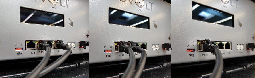
13 7.3 Connections on SMA High-Voltage Active Power Unit (HV APU) APU FUSE (F1) SWITCH BATTERY - 4V AUX PWR BATTERY + E-STOP TERM CAN CAN CAN LAN ADDRESS BAT COM CHARGER + CHARGER - ON / OFF IN OUT SMA Component CHARGER + Designation DC connection for the positive pole of the SMA STPS 60 CHARGER - DC connection for the negative pole of the SMA STPS 60 BATTERY + BATTERY - SWITCH 4 V AUX PWR E-STOP TERM DC connection of the battery for the positive pole DC connection of the battery for the negative pole On/off switch for the battery Connection for an external 4 VDC power supply for the HV APU. This connection is not used in the TS HV 70. Two-pin plug for the optional connection of an emergency off switch CAN bus termination. TERM must be activated (ON) for the first and last CAN bus participant. APU FUSE (F1) Fuse element to protect the HV APU (A G-Fuse 5x0 mm delay (T) in accordance with DIN , type from ESKA, 50 VAC). If the fuse is defected, no operation is possible. CAN IN CAN OUT CAN SMA LAN HV APU master/slave communication HV APU master/slave communication CAN transmission for communication between battery and SMA STPS 60. This connection is not used in the TS HV 70. Modbus TCP/IP transmission for communication between the battery and the SMA STPS 60. In addition, when connecting to an existing network with DHCP, the battery can be monitored using TESVOLT s BatMon software. ADDRESS Further information can be found under point 11.. BAT COM Communication link to the battery module. 11/33
14 7.4 Diagram of connections Diagram of connections with 14 battery modules HV connector set for APU HV module connector set HV cabinet connector set 1/33
15 Diagram of connections with 16 battery modules HV connector set for APU HV module connector set HV cabinet connector set 13/33


16 7.5 Installation steps CAUTION! Installation and servicing may only be performed by qualified personnel. Opening the HV APU voids the warranty. Improper use or incorrect configuration may damage the HV APU. Step View Designation 1 Position the battery cabinet in the installation location, taking into account the requirements listed under point 5 Open the door of the battery cabinet using the included control cabinet key, which can be found on the outside of the door. 3 Connect the two separate TS 40 battery cabinet with the baying connector (cabinet connector) provided 4 CAUTION! Ensure that the battery cabinet is correctly earthed. Connect the earth to the battery cabinet at one of the earthing bolts provided. 5 CAUTION! Ensure that the HV APU is correctly earthed. Mount the HV APU on the upper slide rail and arrange the included cage nuts in the 19 mounting frame, then use the screws provided to fix the HV APU in place at the four fastening points. Note that earthing at the HV APU is absolutely essential. An earthing bolt is attached at the rear of the HV APU. Attach this to any suitable earthing bolt at the battery cabinet using the potential equalisation cable supplied. The two-pin plug for the e-stop connection to the HV APU must be plugged in upon delivery. Until this is plugged in, the HV APU remains inactive. Further information on the e-stop can be found under point 7.6 of this Installation Manual. >> 14/33


17 Step View Designation 6 Mount the battery modules in the slide rails provided and measure their voltage. The DC voltage of undamaged battery modules is approx 50 V. Arrange the included cage nuts in the 19 assembly frame, then use the screws provided to fix the HV APU in place at the four fastening points. Start from the top and work towards the bottom. 7 A cable support rail is included with the cabinets to aid tidy cable laying. The cables (DC connecting cables, rack balancing, BAT COM) can be fastened carefully to this rail using cable ties. ATTENTION! Improper connection of the battery damages the battery and the HV APU. Ensure that connection is carried out properly in accordance with the diagram of connections from chapter Contact the DC module connector, always bearing in mind that there is a serial battery module connection in the high-voltage variant. It is essential here that the colours of the plugs match the colours of the device parts (sockets) on the battery module, i.e. that the red plug goes to the red socket. The plugs must audibly click into place. Incorrect wiring will lead to a short-circuit, and it will be necessary to exchange the battery modules. 9 ATTENTION! Noiseless battery operation cannot be guaranteed if the BAT COM communication cable is improperly connected. Ensure that connection is carried out properly in accordance with the diagram of connections from chapter 7.5. Lay the communication cable for the BAT COM using the included patch cable. Start by running the cable from the HV APU [BAT COM] to the BAT COM IN of the module installed below the HV APU. From there, run the cable from the BAT COM OUT to the BAT COM IN of the next module. The BAT COM OUT of the last battery module remains open. Attention! Ensure correct cabling from the left to the right cabinet. >> 15/33


18 Step View Designation ATTENTION! Improper connection of the rack balancing cables damages the Active Battery Optimizer, which must then be replaced. Ensure that connection is carried out properly in accordance with the diagram of connections from chapter 7.5. Plug in the rack balancing plugs. Start with the battery module underneath the HV APU, where the plug with a bridge from 1 to 4 is fitted into IN, and OUT is connected to the IN of the subsequent battery module. The last battery module in the string must have the plug with a bridge from 1 to 4 fitted into its OUT terminal. Attention! Ensure correct cabling from the left to the right battery cabinet. Connect the DC cable from the STPS 60 to the HV APU (charger). The red plug for connection to the positive terminal and the black plug for connection to the negative terminal are already equipped with touch-proof plugs. Begin by connecting to the SMA STPS 60, before the plugs are connected to the HV APU. To fix the DC cables to the SMA STPS 60 and provide strain relief, fasten the clamps to the C-profile rail above the HV APU. 1 Connect the HV APU s LAN connection to the switch provided by TESVOLT. On this switch, the SMA STPS 60 is also connected to the terminal on the Ethernet interface in position G, as seen in chapter 8. Installation completed! 16/33
 is provided on the device for this purpose.")


19 7.6 E-stop contact The TS HV 70 has an e-stop (emergency stop) function. An externally accessible two-pin plug (type manufactured by WAGO) is provided on the device for this purpose. This electrical connection can be connected to an external control system via the corresponding WAGO socket. The external control system can switch the unit off independently of the communication. There are states: 1. If contacts 1 and of the WAGO plug are connected,. If contacts 1 and of the WAGO plug are open, e.g. after e.g. via an external relay, the e-stop is inactive activating the emergency off switch, then the e-stop is and the HV APU is thus switched on. active and will be shown as active on the HV APU s display. Requirement for the external control system As there is a voltage of 4 VDC across the e-stop and these devices are used internally, an external relay is required to enable correct functioning. This relay can be adapted to the requirements of the external control system used. CAUTION! There is a voltage of 4 VDC across the e-stop based on the potential of the housing. This voltage is generated from the battery voltage, across the power supply unit integrated into the HV APU. Circuit diagram E-Stop Delivery status with E-Stop BRIDGE Single-pole relay 17/33

20 8 Connecting to SMA Sunny Tripower Storage 60 (SMA STPS 60) 8.1 System setup Standard system setup Bat Fuse HV Inverter Manager Output measurement Remote monitoring system Consumption devices Mains Grid System setup with Fuel Save Controllers (FSC) Bat Fuse HV Inverter Manager Output measurement Remote monitoring system Consumption devices Mains Grid 18/33
.")


21 8. Diagram of connections B C D INFORMATION on charging procedure Compatible battery inverters charge automatically based on the parameters stored for the battery and charging infrastructure. Useful installation and planning aids can be found on the website of the manufacturer SMA ( A E H G F Position Designation Description A B AC terminal clamps Grounding Cable cross-section: 35 to 95 mm² 0 Nm, 69 to 150 mm² 30 Nm Please note: When using flexible or very flexible cables, wire end ferrules must be used for the connection. Use a cabel suitable for Min. 75 C C Protection against AC overvoltage SDPs D DC load-break switch SDPs Battery connection: Cable cross-section: 35 to 50 mm² Tightening torque: 0 Nm E DC- terminal clamps Use a cabel suitable for Min. 75 C Please note: When using flexible or very flexible cables, wire end ferrules must be used for the connection. F DC load-break switch For switching DC battery voltage on and off G Ethernet interface x H RS 485 interface not in use Communication interface for communication between the HV APU and the storage SMA Inverter Manager 19/33
22 9 Commissioning 9.1 Commissioning of 1x TS HV 70 ATTENTION! Improper configuration can result in damage to the battery. The parameters which are set affect the charging behaviour of the SMA STPS 60. It is therefore important to set the parameters correctly during commissioning. Requirements: The SMA STPS 60 and SMA Inverter Manager must be installed using the electrical connection procedure indicated by SMA. DC load-break switch on the SMA STPS 60 is set to ON. If HV BatFuse is present: the power switches in the HV BatFuse are closed. AC power protection switches in the distributor of the SMA STPS 60 and SMA Inverter Manager are closed. Procedure: Press the on/off switch on the HV APU. The battery s initiation mode (INIT) will commence. Tap the screen on the battery to activate the display. The number of recognised battery modules will be displayed on the screen. Tap twice next to the display to confirm the correct number. Otherwise check the BAT COM cabling. The Battery is now in the (INIT) mode and the light on the switch will begin to flash. Subsequently, the commissioning process will be started with the SMA LCS Tool. Once the commissioning process is completed successfully, the battery changes to Precharge mode (PRECHG).Once pre-charging has completed, the light on the switch will remain on. On the battery display, the status will be indicated as OK. Now the battery is ready for use. 0/33
23 9. Commissioning of multiple TS HV 70 systems in a master/slave concept ATTENTION! Improper configuration can result in damage to the battery. The parameters which are set affect the charging behaviour of the SMA STPS 60. It is therefore important to set the parameters correctly during commissioning. Requirements: The SMA STPS 60 and SMA Inverter Manager must be installed using the electrical connection procedure indicated by SMA. DC load-break switch on the SMA STPS 60 is set to ON. If HV BatFuse is present: the power switches in the HV BatFuse are closed. AC power protection switches in the distributor of the SMA STPS 60 and SMA Inverter Manager are closed. Procedure: Commissioning must begin with the last slave in the master/slave concept. Press the on/off switch on the HV APU. The battery s initiation mode (INIT) will commence. Tap the screen on the battery to activate the display. The number of recognized battery modules will be displayed on the screen. Tap twice next to the display to confirm the correct number. Otherwise, check the BAT COM cabling. Only for master/slave: If more than one HV APU is connected to a cluster, this query will also appear on the display. The Battery is now in the (INIT) mode and the light on the switch will begin to flash. Subsequently, the commissioning process will be started with the SMA LCS Tool. Once the commissioning process is completed successfully, the battery changes to Precharge mode (PRECHG).Once pre-charging has completed, the light on the switch will remain on. On the battery display, the status will be indicated as OK. Now the battery is ready for use. 1/33


.")
24 10 Shutdown ATTENTION! Risk of electric shock discharging of the capacitors is time controlled. Please wait 15 minutes after switching off the SMA STPS Disconnect the AC fuses of the SMA STPS 60. DC load-break switch on the SMA STPS 60 must not be switched to "OFF". 3. Switch off battery (press the green-lit on/off switch on the HV APU the green LED must go out). When multiple TS HV 70 systems are connected, each HV APU must be switched off. /33

 of approx. 0%.")


25 11 Extending the storage system The capacity and the charging and discharging power of TESVOLT battery systems can be expanded Capacity expansion using the TESVOLT battery storage system New battery modules are delivered with a state of charge (SoC) of approx. 0%. In order to integrate a new battery module into an existing battery system, the existing system must also be brought to a state of charge of 0%. Only then the new battery modules can be installed in the existing system and put into operation. When the system is restarted, the HV APU will call up on the display the number of modules now recognised. If this is correct, confirm by tapping the display twice. The battery s new capacity must also be updated in the SMA STPS 60. You can find useful information on SMA s website ( and in the documents provided by SMA. System with 1 master and 1 slave Expanding SMA STPS 60 capacity IMPORTANT! Up to 4 battery cabinets per SMA STPS 60 can be connected in parallel in a master/slave concept. 3/33


26 System with 1 master and slaves 4/33


27 System with 1 master and 3 slaves 5/33
 Slave (of M1) Cluster 1 Slave 3 (of")
 Cluster 3 Slave 3 (of M3) 0 3 Master 0 1 Slave 1 (of master 4) Slave (of M4) Cluster 4 Slave 3")
28 11. Correctly setting the address selector on the Active Power Unit (SMA HV APU) Left rotary switch Right rotary switch Designation IP address 0 0 Master 0 1 Slave 1 (of master 1) Slave (of M1) Cluster 1 Slave 3 (of M1) 0 1 Master 0 1 Slave 1 (of master ) Slave (of M) Cluster Slave 3 (of M) 0 Master 0 1 Slave 1 (of master 3) Slave (of M3) Cluster 3 Slave 3 (of M3) 0 3 Master 0 1 Slave 1 (of master 4) Slave (of M4) Cluster 4 Slave 3 (of M4) 6/33


29 11.3 Expanding power using the SMA STPS 60 charge controller The charging and discharging power can be increased by increasing the number of used SMA STPS 60 inverters. Up to 0 SMA STPS 60 inverters can be run per Inverter Manager. 7/33
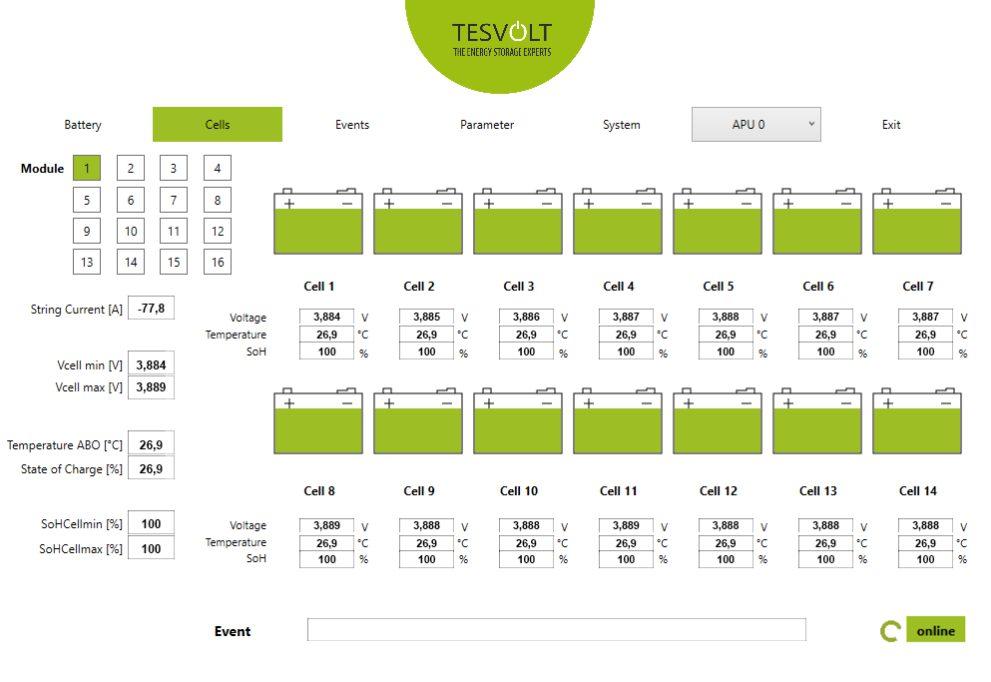
30 1 TESVOLT Battery Monitoring software (BatMon) 1.1 Views and features of TESVOLT Battery Monitoring (BatMon) software TESVOLT BatMon is a software program that can be used to analyse and visualise the battery at the cell level. The software is provided on the USB stick included with delivery and must be installed in a writable folder, e.g. on drive C:, before starting. In order to use the BatMon software to gain insight into the battery, the LAN port on the HV APU must be connected to a DHCP network. Once installation is complete, run the BatMon.exe file. The Communication Port button can be found in the bottom section of the BatMon interface under the menu item System. Ethernet communication must be configured here and the number of the HV APU must be entered subsequently under Select APU. The HV APU number can be found on a sticker affixed to the underside of the HV APU. If Ethernet communication has been properly configured and the connection to the battery is successful, a green spinning circle will appear in the lower right corner of the BatMon interface alongside the indicator online. 8/33
31 9/33
32 1. TESVOLT Battery Monitoring (BatMon) menu structure Battery Cells Events Parameter System Output Battery voltage Charging/discharging current Battery temperature Balancing mode Charging cycle (kwh) SoC (state of charge) SoH (state of health) Warning time Cell voltage Cell temperature SoC (cell) SoH (cell) Event logbook Battery parameters Current errors Firmware update Serial port The battery parameters are password protected. As these parameters directly affect the battery, only certified specialists may configure them. You can request the password directly from TESVOLT GmbH. SoC State of Charge This value indicates the percentage to which the battery has been charged. 100% means that the battery is fully charged. The HV APU can use parameters to determine the state of charge of a cell or battery module and stop the charging process if necessary. This prevents overcharging. The software uses the same function to monitor the discharging process, in order to avoid placing any unnecessary loads on the cells. A minimum state of charge of the battery is defined and the system stops the discharging process when this value is reached. SoH State of Health This value indicates how healthy the cell is. Precise monitoring allows the system to detect differences in performance between individual cells and thus identify damaged or faulty cells. If necessary, the system will shut down and notify the SMA STPS 60 of this. 30/33
33 13 Battery system error and warning messages If errors persist, please contact the TESVOLT Service Line. Event Description Storage system not starting up How to resolve errors Check if the battery wiring (Reverse polarity or plug not contacted correctly). Check the functionality of the A fine wire APU Fuse (F1), which is located on the right front-side of the HV APU and replace it if necessary. Then contact TESVOLT Service. W90 / W936 General General battery error Restart the HV APU using the on/off switch. Check the parameters set on the SMA STPS 60. F91/W937 - Battery High Voltage F9/W938 - Battery Low Voltage Overvoltage in a cell within the battery module Undervoltage in a cell within the battery module The APU equalises the cell voltages. The battery uses undervoltage to detect faulty cells. If hazardous voltages are reached, the battery system opens direct current relays and securely disconnects from the SMA STPS 60. If a voltage limit is reached the battery active -poling disconnect from the SMA STP 60 by means of Direct current relays. Contact TESVOLT Service F93/W939 Battery High Temperature Cell has reached maximum temperature limit Switch off the battery and let it cool to at least 5 C. Check the battery module s cabling. F94/W940 Battery Low Temperature F95/W 941 Battery High Temperature Charge Battery has not been maintained above minimum temperature limit Maximum temperature reached during battery charging Switch off the battery and raise the ambient temperature to at least 5 C. Switch off the battery and let it cool to at least 5 C. Check the battery module s cabling. F96/W 94 Battery Low Temperature Charge F97/W943 - Battery High Current F98/W944 Battery High Current Charge F99 / W945 Switch Contactor Minimum temperature reached during battery charging Charging current too high Charging current too high during battery charging Switch has reported error Switch off the battery and raise the ambient temperature to at least 5 C. Switch off the battery and check the parameters of the battery and the SMA STPS 60. Restart the battery. Switch off the battery and check the parameters of the battery and the SMA STPS 60. Restart the battery. Restart the battery. W 947 BMC internal Internal error in the controller Restart the battery. 31/33

34 14 Maintenance and storage ATTENTION! Before maintenance work, please carry out the steps mentioned under point 10 Shutdown. INFORMATION! For cleaning and maintenance of the SMA STPS 60, see the installation manual for the SMA STPS 60. To guarantee safe operation, all plug connections should be regularly checked by qualified specialists and reinserted if necessary, and cleared of dust and other impurities. Use the BatMon software to check the SoC, SoH, cell voltages and temperatures of the battery modules for irregularities. If you would like to clean the battery cabinet, please use a dry cleaning cloth. Avoid bringing the battery connections into contact with moisture. Solvents must not be used. To guarantee a long battery life, the storage temperature in a given area should be kept between 0 C and 50 C and the cell should be cycled at least every six months. To minimize self-discharge during long periods of storage, the Battery DC connections of the HV APU should be disconnected. This interrupts the 4 VDC power supply built into the APU and thus prevents the battery from discharging. 3/33
35 15 Disposal TESVOLT products are covered by a free-of-charge take-back scheme. For more information, please contact TESVOLT. The batteries may only be disposed of in accordance with the applicable regulations for used batteries. If the battery is damaged, shut it down and begin by contacting your installer or distributor. Ensure that the battery is not exposed to moisture or direct sunlight. Ensure that the battery is rapidly collected by your installer or TESVOLT. Do not dispose of the battery with your household waste! 16 Publishing information TESVOLT TS HV 70 Installation Manual Last updated: Version: A.1 <Technical information is subject to change> We will be happy to answer any questions related to the appearance of warning signals or error messages. Please contact us and have the following information on hand: Serial number of the TESVOLT product The error or warning messages shown on the display Contact details: TESVOLT GmbH Am Alten Bahnhof Lutherstadt Wittenberg Germany Tel: +49 (0) support@tesvolt.com 33/33
36 WE HAVE A THEN FOR ANY WHEN. Your certified TESVOLT partner TESVOLT GmbH Am Alten Bahnhof Lutherstadt Wittenberg Germany FREECALL 0800-TESVOLT TEL +49 (0) support@tesvolt.com
Installation Manual. TS 48 Volt
 Installation Manual TS 48 Volt Installation Manual TESVOLT TS 48 Volt incl. connection of the TS Series to SMA products TS 5 TS 40 TS 50 1 Table of Contents 1 3 4 5 6 7 About this document Safety.1. Needed
Installation and operating instructions. Solar charge controller MPPT 10 A / 20 A Z Z
 Installation and operating instructions Solar charge controller MPPT 10 A / 20 A EN 1 Contents 1. About these instructions... 3 1.1 Applicability... 3 1.2 Users... 3 1.3 Description of symbols... 3 2.
Emergency Power Supply for the OMEGA ACTIVE-System. Operating Instructions
 Emergency Power Supply for the OMEGA ACTIVE-System Operating Instructions Preface Preface These Operating Instructions will help you using the Emergency Power Supply as intended, safely, and advantageously.
T Series (N6052T) Solar Battery Hybrid System. Installation Manual Version 1.1
 Solar Battery Hybrid System. Installation Manual Version 1.1") T Series (N6052T) Solar Battery Hybrid System Installation Manual Version 1.1 Content 1. Safety... 1 1.1 How to Use This Manual... 1 1.2 Safety Rules... 1 1.3 Warning Notices Affixed to the Device... 2
T Series (N6052T) Solar Battery Hybrid System Installation Manual Version 1.1 Content 1. Safety... 1 1.1 How to Use This Manual... 1 1.2 Safety Rules... 1 1.3 Warning Notices Affixed to the Device... 2
BYD Battery-Box HV User Manual Battery-Box H 5.1/6.4/7.7/9.0/10.2/11.5
 Battery-Box H 5.1/6.4/7.7/9.0/10.2/11.5 Version 5.0 Contents 1 General Information... 2 1.1 Validity... 2 1.2 Application... 2 1.3 Intended Use... 2 1.4 Definition... 2 1.5 Identifying The Product... 3
THE ENERGY STORAGE EXPERTS
 TPS POWER STORAGE The all-rounder for grid networks and industry Built to last 30 years 1C charging speed The safest cell technology THE ENERGY STORAGE EXPERTS WE HAVE A THEN FOR ANY WHEN. Our battery
Accessories for Stand-alone inverter SUNNY ISLAND GENMAN
 Accessories for Stand-alone inverter SUNNY ISLAND GENMAN Technical Description GenMan-TEN082730 98-2001230 Version 3.0 EN SMA Solar Technology AG Table of Contents Table of Contents 1 Notes on this manual..............................
B-RAD Select USER MANUAL TABLE OF CONTENTS
 TABLE OF CONTENTS TABLE OF CONTENTS... 1 MANUAL REVISION HISTORY... 2 IMPORTANT SAFETY NOTICE... 3 1.0 General Information... 5 1.1 System Components... 5 1.2 Specifications... 5 1.2.1 Torque Ranges...
Manual. EN Appendix. Lynx Ion BMS 400A / 1000A
 Manual EN Appendix Lynx Ion BMS 400A / 1000A 1. SAFETY INSTRUCTIONS 1.1 In general Please read the documentation supplied with this product first, so that you are familiar with the safety signs en directions
 IU0U automatic charger Read these instructions carefully before the installation and commissioning and keep them in a safe place. Pass it on to the buyer in case of the further sale of the system. Contents
MODEL A96 SERIES. 130Vdc Switchmode Utility Rectifier / Battery Charger. Used with LaMarche Power Cage ECN/DATE
 MODEL A96 SERIES 130Vdc Switchmode Utility Rectifier / Battery Charger Used with LaMarche Power Cage CPN112138 ECN/DATE ISSUE DATE: ECN 17010-12/05 106 BRADROCK DRIVE DES PLAINES, IL. 60018-1967 (847)
Installation Guide B-BOX Pro2.5 ~ 10.0
 Installation Guide B-BOX Pro2.5 ~ 10.0 20170625 Version:2.1 1 / 37 Content Safety... 4 1 Product overview... 5 2 Cabinet terminal introduction... 6 3 Cable outlet of cabinet... 7 4 B-Plus2.5 interface
SOLAR CHARGE CONTROLLER
 SOLAR CHARGE CONTROLLER SCE 1010 / SCE 1515 / SCE 2020 / SCE 3030 Instruction Manual Please read user manual carefully before use. 1.About this manual These operating instructions are part of the product.
Wind Power Inverter WINDY BOY 5000A/6000A
 Wind Power Inverter WINDY BOY 5000A/6000A User Manual WB5A-6A-BA-BEN114530 TBEN-WB50-60A Version 3.0 EN SMA Solar Technology AG Table of Contents Table of Contents 1 Information on this Manual.........................
Lithium-Ion Phosphate Battery
 Lithium-Ion Phosphate Battery US2000 Plus Product Manual Information Version: 1.0 This manual introduces US2000 Plus from Pylontech. Please read this manual before you install the battery and follow the
Installation and Operating Instructions. Solar System Controller ISC3030
 Installation and Operating Instructions Solar System Controller ISC3030 ABOUT THIS MANUAL These operating instructions come with the product and should be kept with it as a reference to all user s of the
DC Master 24/ A
 USERS MANUAL DC Master 24/12 50-60A DC-DC converter MASTERVOLT Snijdersbergweg 93, 1105 AN Amsterdam The Netherlands Tel.: +31-20-3422100 Fax.: +31-20-6971006 www.mastervolt.com ENGLISH Copyright 2015
DIGITAL BATTERY TORQUE WRENCH (BC-RAD SELECT) USER GUIDE
 USER GUIDE") DIGITAL BATTERY TORQUE WRENCH (BC-RAD SELECT) USER GUIDE W.CHRISTIE (INDUSTRIAL) LTD CHRISTIE HOUSE, MEADOWBANK ROAD, ROTHERHAM, SOUTH YORKSHIRE, S61 2NF, UK T: +44(0)1709 550088 F: +44(0)1709 550030 E:
DIGITAL BATTERY TORQUE WRENCH (BC-RAD SELECT) USER GUIDE W.CHRISTIE (INDUSTRIAL) LTD CHRISTIE HOUSE, MEADOWBANK ROAD, ROTHERHAM, SOUTH YORKSHIRE, S61 2NF, UK T: +44(0)1709 550088 F: +44(0)1709 550030 E:
User s Manual. Automatic Switch-Mode Battery Charger
 User s Manual Automatic Switch-Mode Battery Charger IMPORTANT Read, understand, and follow these safety rules and operating instructions before using this battery charger. Only authorized and trained service
USER MANUAL GEBRUIKSAANWIJZING. Phoenix 12/150 Phoenix 24/150 Phoenix 48/150
 USER MANUAL GEBRUIKSAANWIJZING Phoenix 12/150 Phoenix 24/150 Phoenix 48/150 Copyrights 1999, 2000 Victron Energie B.V. All Rights Reserved This publication or part thereoff, may not reproduced in any
Lithium-Ion Phosphate Battery Phantom-S Product Manual
 Lithium-Ion Phosphate Battery Phantom-S Product Manual Information Version: 1.0 This manual introduces Phantom-S from Pylontech. Please read this manual before you install the battery and follow the instruction
Installation and Operating Instructions. Solar System Controller ISC3020
 Installation and Operating Instructions Solar System Controller ISC3020 ABOUT THIS MANUAL These operating instructions come with the product and should be kept with it as a reference to all user s of
User Manual. Solar Charge Controller 3KW
 User Manual Solar Charge Controller 3KW 1 CONTENTS 1 ABOUT THIS MANUAL... 3 1.1 Purpose... 3 1.2 Scope... 3 1.3 SAFETY INSTRUCTIONS... 3 2 INTRODUCTION... 4 2.1 Features... 4 2.2 Product Overview... 5
Inverter / Charger Accessory for Steca Solarix PLI Phase / Parallel Kit. Installation and operating instructions Z01 17.
 Inverter / Charger Accessory for Steca Solarix PLI 5000-48 3-Phase / Parallel Kit Installation and operating instructions GB Z01 17.31 Table of Contents About this Manual... 2 Purpose... 2 Scope... 2 Keywords
Assembly instructions
 Please carefully read the assembly instructions before beginning the installation, operation and maintenance of the solar facility. Noncompliance could cause injury to persons or damage to the equipment.
Lithium Power Supply
 Lithium Power Supply User Manual LPS 1200W-60Ah LPS 1500W-100Ah LPS 2500W-100Ah Compact lithium battery based power supply - for easy acces to 230V and 12V energy, everywhere! V1.1 Safety Instructions
Installation and operating instructions. Solar charge controller 10 A / 15 A / 0 A / 30 A PHOTOVOLTAIK - PHOTOVOLTAICS - PHOTOVOLTAIQUE - FOTOVOLTAICA
 PHOTOVOLTAIK - PHOTOVOLTAICS - PHOTOVOLTAIQUE - FOTOVOLTAICA Installation and operating instructions Solar charge controller 10 A / 15 A / 0 A / 30 A EN 74.86 08.4 1. About this manual These operating
System Monitoring SCHOOLMETERBOX AU
 System Monitoring SCHOOLMETERBOX AU Installation Guide SMETER-IEN084710 98-00013210 Version 1.0 EN SMA Solar Technology AG Table of Contents Table of Contents 1 Notes on this Manual..............................
Installation and Operating Instructions. MPPT Solar System Controller ISC3040
 Installation and Operating Instructions MPPT Solar System Controller ISC3040 ABOUT THIS MANUAL These operating instructions come with the product and should be kept with it as a reference to all user s
Operating Instructions. bluesmart Active
 Table of contents 1. Overview 3 2. Safety 3 2.1 Symbols in these instructions 3 2.2 Intended use 4 2.3 Responsibility of the operator 4 3. Setup and function 4 3.1 Brief description 4 3.2 Overview 5 3.3
ENGLISH SAFETY INSTRUCTIONS. Recommendations for safe operation. Operator safety. General warnings
 Safety and use instructions LifeSpeed iq TM - 3-phase chargers ENGLISH SAFETY INSTRUCTIONS GOALS OF THIS MANUAL This manual is aimed at any authorized personnel wanting to use a 3-phase LifeSpeed iq TM
User Manual Solar Charge Controller 3KW
 User Manual Solar Charge Controller 3KW Version: 1.3 CONTENTS 1 ABOUT THIS MANUAL... 1 1.1 Purpose... 1 1.2 Scope... 1 1.3 SAFETY INSTRUCTIONS... 1 2 INTRODUCTION... 2 2.1 Features... 2 2.2 Product Overview...
GEatom306KHF-5U Three-phase Grid-Tied Battery Inverter. Version 1.1. Global Mainstream Dynamic Energy Technology Ltd. 1
 GEatom306KHF-5U Three-phase Grid-Tied Battery Inverter Version 1.1 Global Mainstream Dynamic Energy Technology Ltd. 1 Content Prelude... 4 1. Safety... 5 1.1 How to Use This Manual... 5 1.2 Safety Rules...
USER MANUAL MPS 1-5KW SERIES
 USER MANUAL MPS 1-5KW SERIES Low Series Frequency Solar and Wind Power Charging Inverter CONTENTS 1 WWW.NEXTGENNRG.COM 1. Introduction... 3 2. Profile Structure 4 2.1. Working Principle 4 2.2.Product Features..5
PV Inverter SUNNY MINI CENTRAL 9000TL / 10000TL / 11000TL with Reactive Power Control
 PV Inverter SUNNY MINI CENTRAL 9000TL / 10000TL / 11000TL with Reactive Power Control User Manual SMC9-11TLRP-BA-en-30 TBEN-SMCTLRP Version 3.0 EN SMA Solar Technology AG Table of Contents Table of Contents
SOLAR CHARGE CONTROLLER N 2010 IN 2011/ N 2012/ N 2014
 SOLAR CHARGE CONTROLLER N 2010 IN 2011/ N 2012/ N 2014 Instruction Manual Please read user manual carefully before use. CE 1.About this manual These operating instructions are part of the product. ~ Read
Operating instructions. sonnenprotect for operators. KD-337 Part no Version X00.
 Operating instructions for operators sonnenprotect 1300 KD-337 Part no. 22010 Version X00 info@sonnenbatterie.de www.sonnenbatterie.de EN IMPORTANT Read this documentation carefully before operation. Retain
Operating conditions of VRLA batteries in HVCBS and LVDBS Systems
 Operating conditions of VRLA batteries in HVCBS and LVDBS Systems 1 GENERAL INFORMATION It is required to mandatorily adhere to these Conditions of Operation. This document should be filled in (the last
MP V 8A Electronic Smart Charger. Instruction and Information Manual
 MP7428 12V 8A Electronic Smart Charger Instruction and Information Manual In order to ensure correct and safe usage of your battery charger, you should read these instructions carefully. Please retain
Lithium-Ion Phosphate Energy Storage System PowerCube-X1 Operation Manual
 Lithium-Ion Phosphate Energy Storage System PowerCube-X1 Operation Manual Information Version: 2.1 This manual introduces PowerCube-X1 from Pylontech. PowerCube-X1 is a high voltage Lithium-Ion Phosphate
I. Safety precautions
 . Safety precautions The items described in these instructions and on the inverter itself are very important so that you can use the inverter safely, prevent injury to yourself and other people around
Installation and operating instructions. Solar charge controller Solarix MPPT 1010 and Z Z
 Installation and operating instructions Solar charge controller Solarix MPPT 1010 and 2010 EN 730927 Z04 1440 730927 Z04 1440 1 Contents 1. About these instructions...3 1.1 Applicability...3 1.2 Users...3
Exchange of rollers from the XTS-Mover
 Service documentation for AT901-0050-0550 and AT9011-00x0-0550 Version: Date: 1.0 0.10.017 Table of contents Table of contents 1 Foreword... 5 1.1 Notes on the documentation... 5 1. Documentation issue
Lithium-Iron Phosphate Battery US2000B Product Manual
 Lithium-Iron Phosphate Battery US2000B Product Manual Information Version: 1.0 Pylon Technologies Co., Ltd. No. 73, Lane 887, ZuChongzhi Road, Zhangjiang Hi-Tech Park Pudong, Shanghai 201203, China Zip
The Brose e-bike system. Instructions for use
 The Brose e-bike system Instructions for use Instructions for use of Brose e-bike system Reference number: BDA_BeBS_MY2017_en_v4.0 (valid for software of display unit.321) 2 Table of contents Figures...
NEW SOLAR CHARGE CONTROLLERS
 190 SOLAR CHARGE CONTROLLERS Steca Solarix 2020-x2 Dual battery charge controller The Steca Solarix 2020-x2 is a state-of-the-art dual battery charge controller that is ideal for use in leisure applications.
User Guide. Lubricus Lubrication System LUB-D1/LUB-D2/LUB-D3/LUB-D4 (24 VDC)
") User Guide Lubricus Lubrication System LUB-D1/LUB-D2/LUB-D3/LUB-D4 (24 VDC) version 04/2013 Content General Information 3 Warning 3 Scope of Supply 3 Overview 3 General safety details 4 Intended use 4
User Guide Lubricus Lubrication System LUB-D1/LUB-D2/LUB-D3/LUB-D4 (24 VDC) version 04/2013 Content General Information 3 Warning 3 Scope of Supply 3 Overview 3 General safety details 4 Intended use 4
Installation Guide Kratos (B10L)
") Installation Guide Kratos (B10L) Rev 1.1_Mar.2017 1/ 37 Content Safety... 3 1 Product Overview... 4 2 Cabinet terminal introduction... 5 3 Cable outlet of cabinet... 6 4 B10L2.5M interface and terminal
Installation Guide Kratos (B10L) Rev 1.1_Mar.2017 1/ 37 Content Safety... 3 1 Product Overview... 4 2 Cabinet terminal introduction... 5 3 Cable outlet of cabinet... 6 4 B10L2.5M interface and terminal
Operating Manual MP-3739
 Operating Manual MP-3739 1 About this manual These operating instructions come with the product and should be kept for the life of the product for proper installation and usage. Read these operating instructions
Lithium-Ion Phosphate Battery US2000(Version B) Product Manual
 Product Manual") Lithium-Ion Phosphate Battery US2000(Version B) Product Manual Information Version: 1.0 This manual introducesus2000 (Version B) from Pylontech. Please read this manual before you install the battery and
Lithium-Ion Phosphate Battery US2000(Version B) Product Manual Information Version: 1.0 This manual introducesus2000 (Version B) from Pylontech. Please read this manual before you install the battery and
Rechargeable Li-ion Battery US3000 Product Manual
 Rechargeable Li-ion Battery US3000 Product Manual Information Version: 2.1 This manual introduces US3000 from Pylontech. Please read this manual before you to install the battery and follow the instruction
Operating instructions Accu Jet
 Operating instructions Accu Jet Keep for future use! Ident number: 04.8800.000 Air Line Table of contents 1 Scope of delivery... 4 2 Operator instructions... 5 3 Safety... 6 3.1 Intended use...8 4 Description
Uninterruptible Power Supply ERA LCD 0.65 ERA LCD 0.85 ERA LCD 1.1. User s manual
 Uninterruptible Power Supply ERA LCD 0.65 ERA LCD 0.85 ERA LCD 1.1 User s manual Index Safety Warnings...2 1 Introduction...3 2 General Characteristics...4 3 Receipt and site selection...4 4 EXTERNAL
Fuse state indicator MEg72. User manual
 Fuse state indicator MEg72 User manual MEg Měřící Energetické paráty, a.s. 664 31 Česká 390 Czech Republic Fuse state indicator MEg72 User manual Fuse state indicator MEg72 INTRODUCTION The fuse state
8 Troubleshooting and Maintenance
 8 Troubleshooting and Maintenance 8.1 Troubleshooting 8.1.1 Troubleshooting of LED Indicators See Tab. 7-4 State Descriptions of LED Indicators for the definition. Fault Type LED indicators and LCD screen
User Manual Digital Energy Uninterruptible Power Supply ML Series UPS VA GE Digital Energy Power Quality
 GE Digital Energy Power Quality User Manual Digital Energy Uninterruptible Power Supply ML Series UPS 350-500-700-1000 VA GE imagination at work GB User Manual Digital Energy Uninterruptible Power Supply
USER MANUAL. IPS home inverters with UPS function. IPS home inverter manual
 USER MANUAL IPS home inverters with UPS function Suitable for UPS: - IPS300-SIN - IPS300-SIN-WM - IPS300-SIN-DC - IPS600-SIN - IPS600-SIN-WM - IPS600-SIN-DC - IPS1000-SIN - IPS1000-SIN-DC - IPS1600-SIN
DLT-U1100 UPS Uninterruptible Power Supply Manual V1.00. Industrial PCs applied in
 Industrial PCs applied in / Logistics and Warehouse / Heavy Duty / Fleet Management / Stationary and Automation DLT-U1100 UPS Uninterruptible Power Supply Manual V1.00 IMPORTANT: Read this manual carefully.
BYD Battery-Box LV Installation Guidance
 Battery-Box L 3.5/7.0/10.5/14.0 Version1.0 1 / 33 Contents 1 SAFETY... 6 2 PRODUCT OVERVIEW... 7 3 BCU INTRODUCTION... 7 4 DESCRIPTION OF B-PLUS L 3.5 INTERFACE AND TERMINAL... 8 5 PREPARATION... 9 5.1
Multi-Mover Charger for model L25
 Multi-Mover Charger for model L25 Important safety instruction. Keep these instructions. This manual contains important instructions for the safety of the user and the operation of the device. 1. SYMBOLS
INTRODUCTION. Specifications. Operating voltage range:
 INTRODUCTION INTRODUCTION Thank you for purchasing the EcoPower Electron 65 AC Charger. This product is a fast charger with a high performance microprocessor and specialized operating software. Please
CX-SERIES ADVANCED BATTERY CHARGER
 CX-SERIES ADVANCED BATTERY CHARGER Table of Content 1. IMPORTANT SAFETY INFORMATION... 2 1-1 General Safety Precautions... 2 1-2 Battery Precautions... 2 2. FEATURES... 3 2-1 Battery Charging Curve...
Installation Guidance. B-Box Pro2.5~10.0
 Installation Guidance B-Box Pro2.5~10.0 Rev 2.1_Jul.2017 1/ 38 Content Safety... 4 1 Product Overview... 5 2 Cabinet terminal introduction... 6 3 Cable outlet of cabinet... 7 4 B-Plus2.5 interface and
Automatic Battery Charger Switching mode with Micro-controlled Input: Vac / Output: 12Volt DC
 Automatic Battery Charger Switching mode with Micro-controlled Input:220-260Vac / Output: 12Volt DC User s Manual and Important Safety Information Model: OC-SW121080 / OC-SW121160 / OC-SW121210 FEATURES
User Manual. Digital Energy Uninterruptible Power Supply ML Series UPS VA. GE Digital Energy Power Quality. GE imagination at work
 GE Digital Energy Power Quality User Manual Digital Energy Uninterruptible Power Supply ML Series UPS 350-500-700-1000 VA GE Consumer & Industrial SA General Electric Company CH 6595 Riazzino (Locarno)
System description Off-Grid Systems with SUNNY ISLAND 4.4M / 6.0H / 8.0H
 System description Off-Grid Systems with SUNNY ISLAND 4.4M / 6.0H / 8.0H ENGLISH SI44M-80H-12-OffGrid-IA-en-11 Version 1.1 Legal Provisions SMA Solar Technology AG Legal Provisions The information contained
Operating Instructions
 Operating Instructions Ex UPS Combination of > 8265/5 GUBox control panel > 8316 battery box Contents 1 Contents 1 Contents 2 2 General Information 2 3 Safety Instructions 2 4 Conformity to standards 3
Off Grid Solar Inverter. LVS 50M User Manual
 Off Grid Solar Inverter LVS 50M User Manual Save This Manual Please read this manual carefully prior to installation, wiring, operation and maintenance of the LVS M Series. This manual contains important
SOS SERIES SOS1 SOS2. Spares On Site Battery Cabinet Installation Guide rEV3
 Atlantic Battery Systems 1065 Market Street Paterson, NJ 07513 Phone: (800) 875-0073 Fax: (973) 523-2344 sales@atbatsys.com www.atbatsys.com SOS1 SOS2 SOS SERIES Spares On Site Battery Cabinet Installation
Swing Piston Compressors and Vacuum Pumps
 Swing Piston Compressors and Vacuum Pumps NPK 018 AC Pressure NPK 018 DC Pressure NPK 018 AC Vacuum NPK 018 DC Vacuum Operating and Installation Instructions Read and observe these Operating and Installation
USER'S GUIDE. WiseHP11 SINGLE PHASE HIGH PRECISION AVR SERVO-MOTOR AUTOMATIC VOLTAGE STABILIZER
 USER'S GUIDE WiseHP11 SINGLE PHASE HIGH PRECISION AVR SERVO-MOTOR AUTOMATIC VOLTAGE STABILIZER LEN.MAN.STA.145 Rev.5.00/2010 CONTENTS 1. SAFETY INSTRUCTIONS 1 2. INTRODUCTION 2 3. FRONT PANEL AND INSIDE
Assembly and Maintenance Manual Type ASNU
 Assembly and Maintenance Manual Type ASNU Hatschekstr.36 69126 Heidelberg Germany Tel +49(0)6221 30470 Fax +49(0)6221 304731 info@stieber.de www.stieber.de Date of issue: 30.05.2018 GB Revision: 0 U:\EngUsers\!ProduktDoku\1AAA_Einbauerklaerung_Wartungsanleitung_Konformitaetserklaerung\1AAA_Wartungsanleitungen\Orginal_Worddatei\_ASNU.docx
Safety, Installation And Operating Instructions For The Following Battery Charger Models: i2412, i3612, i4809, i2425, i3625, and i4818
 Safety, Installation And Operating Instructions For The Following Battery Charger Models: i2412, i3612, i4809, i2425, i3625, and i4818 IMPORTANT NOTICE: Please save and read these safety, operating and
24V HEAVY DUTY JUMP STARTER/ POWER BANK MB3752. Storage. Specifications
 Storage Warning! When not in use store your instruction manual and product in a safe and dry place. Before re-use after storage it is recommended that the product is checked by a suitably qualified person
OPERATION & MAINTENANCE INSTRUCTIONS
 AUTOMATIC BATTERY CHARGER / MAINTAINER MODEL NO: CBO9-6/12 PART NO: 6267020 OPERATION & MAINTENANCE INSTRUCTIONS LS0615 INTRODUCTION Thank you for purchasing this CLARKE product. Before attempting to use
B-Box Pro 2.5~10.0 User Manual
 B-Box Professional user manual B-Box Pro 2.5~10.0 User Manual 20170323 Version: 2.2 Copyright BYD Company Limited. All rights reserved. Without the written consent of BYD Company, no entity or individual
Operating Manual SUNNY ISLAND 3.0M / 4.4M / 6.0H / 8.0H SUNNY REMOTE CONTROL. SI30M-44M-60H-80H-BE-en-33 Version 3.3 SUNNY REMOTE CONTROL
 Warning Operating Manual SUNNY ISLAND 3.0M / 4.4M / 6.0H / 8.0H SUNNY REMOTE CONTROL SUNNY REMOTE CONTROL Grid / Generator Memory Card Load ENGLISH SI30M-44M-60H-80H-BE-en-33 Version 3.3 Legal Provisions
Installation Guide Smart-UPS On-Line SRT1000/1500 UXI-NCLI, SRT1000/1500 UXI-LI, Tower/Rack-Mount
 Installation Guide Smart-UPS On-Line SRT1000/1500 UXI-NCLI, SRT1000/1500 UXI-LI, Tower/Rack-Mount Important Safety Messages Read the instructions carefully to become familiar with the equipment before
UP100AC INSTRUCTION MANUAL
 UP100AC AC/DC Charger INSTRUCTION MANUAL 100W 10A TABLE OF CONTENTS Introduction... 2 Special Features... 4 Warning and Safety Notes... 6 Lithium Battery Connection Diagram... 10 Operation Diagram - Homepage...
On Line UPS. LUC 1000E / LUC 2000E / LUC 3000E User Manual
 On Line UPS LUC 1000E / LUC 2000E / LUC 3000E User Manual Save This Manual Please read this manual carefully prior to storage, installation, wiring, operation and maintenance of the UPS. This manual contains
Match 19" GE Digital Energy. Uninterruptible Power Supply VA. Technology for the Digital World. Match 19" UPS.
 Match 19" Uninterruptible Power Supply 700-1500 VA Manufactured by: General Electric Company Telephone +41 (0)91 / 850 51 51 CH 6595 Riazzino (Locarno) Fax +41 (0)91 / 850 51 44 Switzerland Website www.gedigitalenergy.com
Central Inverter SUNNY CENTRAL 500CP-JP / 500CP XT / 630CP XT / 720CP XT / 760CP XT / 800CP XT / 850CP XT / 900 CP XT
 Central Inverter SUNNY CENTRAL 500CP-JP / 500CP XT / 630CP XT / 720CP XT / 760CP XT / 800CP XT / 850CP XT / 900 CP XT Maintenance Manual SCCP-WH-B4-en-20 98-4046720 Version 2.0 EN SMA Solar Technology
Installation - Quick Reference Guide Off-Grid Systems
 Installation - Quick Reference Guide Off-Grid Systems Off-Grid Systems with Sunny Island 6.0H / 8.0H Off-Grid-IAS-en-20 Version 2.0 ENGLISH Legal Provisions SMA Solar Technology AG Legal Provisions The
MAKING MODERN LIVING POSSIBLE. UniLynx Indoor Installation Manual. ULX 1800i ULX 3000i ULX 3600i ULX 5400i SOLAR INVERTERS
 MAKING MODERN LIVING POSSIBLE UniLynx Indoor Installation Manual ULX 1800i ULX 3000i ULX 3600i ULX 5400i SOLAR INVERTERS Contents Contents 1. Introduction 2 Introduction 2 Installation Sequence 2 Important
ACCUSENSE CHARGE SERIES ON/OFF BOARD FULLY AUTOMATIC BATTERY CHARGER
 ACCUSENSE CHARGE SERIES ON/OFF BOARD FULLY AUTOMATIC BATTERY CHARGER SPECIFICATIONS: *Photo for reference only* Part number 8890439 Mode Select: Selects Battery Type Refer to Section 6. IMPORTANT: READ
Assembly and Maintenance Manual Type AS
 Assembly and Maintenance Manual Type AS Hatschekstr.36 69126 Heidelberg Germany Tel +49(0)6221 30470 Fax +49(0)6221 304731 info@stieber.de www.stieber.de Date of issue: 30.05.2018 GB Revision: 0 U:\EngUsers\!ProduktDoku\1AAA_Einbauerklaerung_Wartungsanleitung_Konformitaetserklaerung\1AAA_Wartungsanleitungen\Orginal_Worddatei\_AS.docx
OPERATION & MAINTENANCE INSTRUCTIONS
 AUTOMATIC BATTERY CHARGER / MAINTAINER MODEL NO: CBO9-12 PART NO: 6267025 OPERATION & MAINTENANCE INSTRUCTIONS LS0315 INTRODUCTION Thank you for purchasing this CLARKE product. Before attempting to use
OPERATION & MAINTENANCE INSTRUCTIONS
 AUTOMATIC BATTERY CHARGER / MAINTAINER MODEL NO: CBO9-12 PART NO: 6267025 OPERATION & MAINTENANCE INSTRUCTIONS ORIGINAL INSTRUCTIONS LS0118 - ISS 3 INTRODUCTION Thank you for purchasing this CLARKE product.
PURE SINE WAVE DC TO AC POWER INVERTER
 PURE SINE WAVE DC TO AC POWER INVERTER 60S-12A / 60S-24A 60S-12E / 60S-24E 100S-12A / 100S-24A 100S-12E / 100S-24E 150S-12A / 150S-24A 150S-12E / 150S-24E Instruction manual SINE WAVE INVERTER Please read
Automatic Battery Charger Switching mode with Micro-controlled Input: Vac / Output: 12Volt DC
 Automatic Battery Charger Switching mode with Micro-controlled Input:220-260Vac / Output: 12Volt DC User s Manual and Important Safety Information Model: OC-SW121080 / OC-SW121160 / OC-SW121210 FEATURES
B-Box Pro 13.8 User Manual
 B-Box Professional user manual B-Box Pro 13.8 User Manual Rev 1.0_July.2017 Copyright BYD Company Limited. All rights reversed. Without the written consent of BYD Company, any entity or individual shall
BMS16. Thanks for your purchasing the BMS16 for your vehicle.
 BMS16 BMS for 2S-16S LiPo & LiFe Low power consumption High accuracy 2.8 TFT LCD display Programmable Thanks for your purchasing the BMS16 for your vehicle. Read the ENTIRE instruction manual to become
Operating Instructions (Translation)
") Product Description Definition The ANTARES RCU consists of the ANTARES Head Module and the ANTARES Connection Module. The ANTARES Head Module contains a CPU, communication interface and power pack. In
Product Description Definition The ANTARES RCU consists of the ANTARES Head Module and the ANTARES Connection Module. The ANTARES Head Module contains a CPU, communication interface and power pack. In
System description Multicluster Systems with Stand-Alone Grid or Increased Self-Consumption and Battery-Backup Function
 System description Multicluster Systems with Stand-Alone Grid or Increased Self-Consumption and Battery-Backup Function Sunny Island 6.0H / 8.0H and Multicluster-Box 12 / NA-Box 12 / Grid-Connect-Box 12
BYD Battery-Box Pro User Manual Battery-Box Pro 13.8
 Battery-Box Pro 13.8 Version 4.0 Contents 1 General Information... 3 1.1 Validity... 3 1.2 Application... 3 1.3 Intended use... 3 1.4 Battery-Box definition... 3 1.5 Identifying the Product... 3 2 Safety...
3.3kWh Battery Pack Specification 3.3
 3.3kWh Battery Pack Specification 3.3 DATE Revision Date : MODEL P/N 48V 3.3kWh : Aug. 30. 2016 R4863P3S CONTENTS 1. Features 2. Outline Dimensions 3. Technical Data 4. Product Composition 5. LED indicators
USER MANUAL. Blazer Vista 1000/1400/2000. Uninterruptible Power System
 USER MANUAL Blazer Vista 1000/1400/2000 Uninterruptible Power System IMPORTANT SAFETY INSTRUCTIONS SAVE THESE INSTRUCTIONS This manual contains important instructions for model Blazer Vista 1000/1400/2000
Advanced Hybrid Wind / Solar Charge Controller. User Manual
 Advanced Hybrid Wind / Solar Charge Controller User Manual Safety 1. Please read the instructions carefully prior to product use or installation and refer back to them throughout the installation. 2. This
Drive Unit e-drive1. Installation instructions 04/2014. English translation of the original German installation instructions
 Drive Unit e-drive1 Installation instructions 04/2014 English translation of the original German installation instructions Contents Foreword... 3 Availability... 3 Structural features in the text... 3
MODEL A97 SERIES. Switchmode Utility Rectifier/Battery Charger ECN/DATE
 MODEL A97 SERIES Switchmode Utility Rectifier/Battery Charger CPN108172 ISSUE DATE: 16071 7/03 ECN/DATE 106 BRADROCK DRIVE DES PLAINES, IL. 60018-1967 (847) 299-1188 FAX: (847)299-3061 Page 1 of 7 INSTRUCTION