CONTENTS. Advisory Acoustics Fabric Cleaning Information Installation Power Down Operation Underbed Light...
|
|
|
- Alannah Sharon Summers
- 5 years ago
- Views:
Transcription

1 owners manual 300
 MATT-FRM Do not contact retail store or dealer.")
2 CONTENTS Advisory... 3 Acoustics... 5 Fabric Cleaning Information... 5 Installation... 6 Power Down Operation... 9 Underbed Light Remote Control Function Remote Control Programming Troubleshooting Accessories Warranty If adjustable base does not operate or if parts are missing, call: (844) MATT-FRM Do not contact retail store or dealer.
3 ADVISORY IMPORTANT INFORMATION READ THE FOLLOWING INFORMATION CAREFULLY BEFORE USING THIS PRODUCT WARNING FOR OPTIMUM ADJUSTABLE BASE OPERATION, USE A GROUNDED, ELECTRICAL SURGE PROTECTION DEVICE (NOT INCLUDED). FAILURE TO USE A SURGE PROTECTION DEVICE COULD COMPROMISE SAFETY OR CAUSE PRODUCT MALFUNCTION. ELECTRICAL RATING Electrical components are rated for V, 50/60Hz, 1.5A. ELECTRICAL GROUNDING This product is equipped with a polarized or grounded electrical power cord. The power cord will only fit into a grounded, electrical surge protection device (not included) or a grounded electrical outlet. WARRANTY WARNING Do not open any control boxes, motors or remote control devices (with the exception of the remote control and power down box battery compartments). The product warranty will be void if these components are tampered with. Do not attempt to alter component wiring or adjust or modify the structure of the product in any way or the warranty will be void. Any repair or replacement of base parts must be performed by authorized personnel. PRODUCT RATINGS The base lift motors are not designed for continuous use. Reliable operation and full life expectancy will be realized as long as the lift motor operation does not exceed five (5) minutes over a forty-five (45) minute period, or approximately 11% duty cycle. Any attempt to circumvent or exceed product ratings will shorten the life expectancy of the product and may void the warranty. The recommended maximum weight (including mattress) is 700 lb (317 kg) distributed evenly across the base. This product is not designed to support or lift this amount in the head or foot sections alone. Note: Exceeding the recommended weight restrictions could damage the base and void the warranty. For best performance, consumers should enter and exit the adjustable base with the base in the flat (horizontal) position. Avoid placing entire weight on head or foot section of the base, including when in the raised position. DO NOT STAND ON BASE AT ANY TIME. UL (Underwriters Laboratories) recognized components. CFR 1633 approved for use with most mattresses. Assembled in USA. LUBRICATION This product is designed to be maintenance free. The lift motors are permanently lubricated and sealed no additional lubrication is required. Do not apply lubricant to lift motor lead screws or any nylon nuts or the base may inadvertently creep downward from the elevated position. 300 Adjustable Base Owners Manual b 3
4 ADVISORY IMPORTANT INFORMATION READ THE FOLLOWING INFORMATION CAREFULLY BEFORE USING THIS PRODUCT SMALL CHILDREN / PETS WARNING After the base is unboxed, immediately dispose of packaging material as it can smother small children and pets. To avoid injury, children or pets should not be allowed to play under or on the base. Children should not operate this base without adult supervision. PACEMAKER WARNING This product produces a vibrating sensation. It is possible that individuals with heart-assist pacemakers may experience a sensation similar to exercise. Consult physician for complete information. HOSPITAL USE DISCLAIMER This base is designed for in-home use only. It is not approved for hospital use and does not comply with hospital standards. Do not use this base with tent type oxygen therapy equipment, or use near explosive gases. SERVICE REQUIREMENTS Service technicians are not responsible for moving furniture, removing headboards and footboards or any items required to perform maintenance on the base. In the event the technician is unable to perform service due to lack of accessibility, the service call will be billed to the purchaser and the service will have to be rescheduled. FCC COMPLIANCE The equipment has been tested and found to comply with the limits for a Class B digital device, pursuant to Part 15 of the FCC Rules. These limits are designed to provide reasonable protection against harmful interference when the equipment is operated in a residential environment. This equipment generates, uses, and can radiate radio frequency energy and, if not installed and used in accordance with the instruction manual, may cause harmful interference to radio communications. However, there is no guarantee that interference will not occur in a particular installation. If this equipment does cause harmful interference to radio or television reception, which can be determined by turning off the equipment off and on, the user is encouraged to try to correct the interference by one or more of the following measures: - Reorient or relocate the receiving antenna - Increase the separation between the equipment and receiver. - Connect the equipment into an outlet on a circuit different from that to which the receiver is connected. - Consult the dealer or an experienced radio/tv technician for help. Radio Frequency = 2.4GHz Adjustable Base Owners Manual b
5 ACOUSTICS LIFTING/LOWERING MECHANISMS The lift/lower feature will emit a minimal humming sound during operation. This is normal. During operation, the lift arm wheels make contact with the platform support of the base. This applies slight tension on the moving components and resonance is reduced to a minimum level. If excessive noise or vibration is experienced, reverse the movement action (up or down) of the base with the remote control. This should realign the base s activating mechanisms to the proper operational position. FABRIC CLEANING INFORMATION Spot clean only with water based shampoo or foam upholstery cleaner. Pretest a small, inconspicuous area before proceeding. Do not over wet. Do not use solvents to spot clean. Pile fabrics may require brushing with a non-metallic, stiff bristle brush to restore appearance. Hot water extraction or steam cleaning is not a recommended cleaning method. To prevent overall soiling, frequent vacuuming or light brushing with a non-metallic stiff bristle brush to remove dust and grime is recommended. When cleaning a spill, blot immediately to remove spilled material. Clean spots or stains from the outside to the middle of the affected area to prevent circling. Use a professional furniture cleaning service when an overall soiled condition is apparent. 300 Adjustable Base Owners Manual b 5


 Bed Legs (1)")
 Control Box")

 (1) Warranty")

")
 factory attached to")


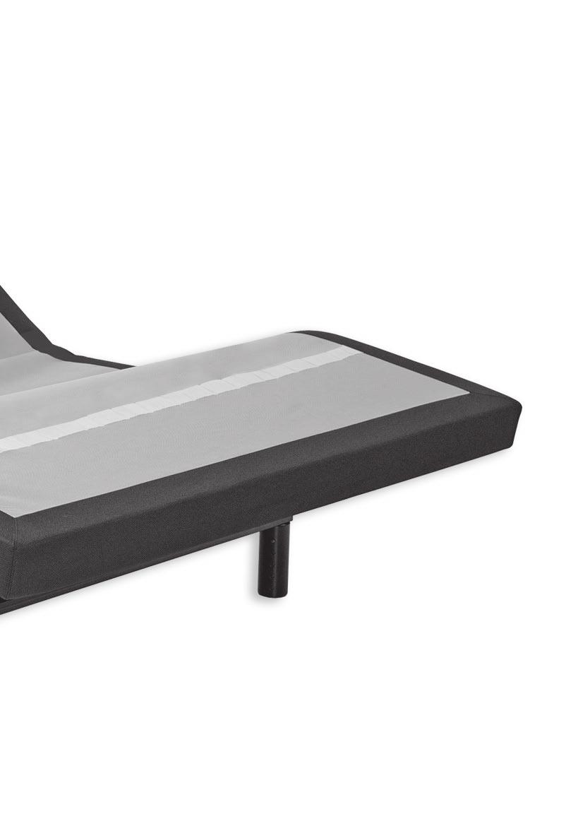
6 INSTALLATION For installation and setup, complete the following procedures, in the order indicated below and on the following pages: STEP 1 Before discarding any packing materials, check the adjustable base shipping carton and verify the following items are included: (4) Bed Legs (1) Remote Control (3) AAA Batteries (1) Control Box (1) Power Supply (includes power brick, electrical feed cord, and electrical power cord) (1) Warranty Activation Card (1) Quick Setup Guide WARRANTY ACTIVATION CARD QUICK SETUP GUIDE LEG (4 pieces) POWER SUPPLY (power brick, electrical feed cord, and electrical power cord) factory attached to base, no assembly required 3 - AAA BATTERIES CONTROL BOX REMOTE CONTROL Adjustable Base Owners Manual b
. Push pin in to adjust leg height (achieve leg height of 6 inches to 10 inches).")
7 INSTALLATION STEP 2 Remove the hardware box. Cut zip-tie and remove mattress retainer. STEP 3 Install (4) legs into the base frame. Simply screw each leg into a tapped hole at the corner of the base frame (FIGURE 1). Push pin in to adjust leg height (achieve leg height of 6 inches to 10 inches). WARNING AT LEAST TWO PEOPLE ARE RECOMMENDED FOR HANDLING AND MOVING ADJUSTABLE BASE. FIGURE 1 PUSH PIN IN TO ADJUST LEG HEIGHT (6 INCHES TO 10 INCHES) LEGS SCREW INTO TAPPED HOLE AT EACH CORNER CAUTION DO NOT ATTEMPT TO SCREW LEGS INTO ANY OTHER INSERTS. THIS WILL DAMAGE PRODUCT. STEP 4 Carefully lift the adjustable base from the shipping carton, keeping the unit top-side-down. Uncoil and extend out power cord from base. WARNING POWER CORDS MUST NOT INTERFERE WITH ANY ADJUSTABLE BASE MECHANISMS. 300 Adjustable Base Owners Manual b 7
 (FIGURE 2). Note: Make sure to orient batteries properly.")
 END TABS BATTERY COMPARTMENT DOOR PRESS IN ON TAB AND LIFT OUT TO REMOVE BATTERY COMPARTMENT DOOR. INSERT TABS IN TAB SLOTS AND SNAP IN TO REPLACE.")
8 INSTALLATION STEP 5 Remove the plastic packaging from the base frame. Carefully rotate the adjustable base over to position the base so it is resting on its legs. STEP 6 Install batteries in remote control (3-AAA, included) (FIGURE 2). Note: Make sure to orient batteries properly. Briefly activate all functions of the base with the remote control to verify all features are in working order. If base does not operate, refer to the Troubleshooting section of this manual. FIGURE 2 NEGATIVE (-) END TABS BATTERY COMPARTMENT DOOR PRESS IN ON TAB AND LIFT OUT TO REMOVE BATTERY COMPARTMENT DOOR. INSERT TABS IN TAB SLOTS AND SNAP IN TO REPLACE. POSITIVE (+) END BOTTOM OF REMOTE CONTROL STEP 7 Return base to the level position. STEP 8 Install mattress on adjustable base. Typical B-1 Model adjustable base installation is now complete Adjustable Base Owners Manual b
 power brick (FIGURE 3) and (2) 9 volt batteries (not included).")
 UNDERSIDE OF POWER BRICK INSTALL (2) 9 VOLT BATTERIES *BATTERIES")
9 POWER DOWN OPERATION To lower the base to the flat position during an electrical power outage, complete the following procedure: STEP 1 Verify power is unplugged from electrical power source. STEP 2 Locate (1) power brick (FIGURE 3) and (2) 9 volt batteries (not included). FIGURE 3 POWER BRICK STEP 3 Install (2) 9 volt batteries in power brick (FIGURE 4). FIGURE 4 BATTERY COMPARTMENT DOOR (push down and slide off to remove) UNDERSIDE OF POWER BRICK INSTALL (2) 9 VOLT BATTERIES *BATTERIES NOT INCLUDED 300 Adjustable Base Owners Manual b 9
. FIGURE 5 HEAD DOWN FOOT DOWN STEP 5 Remove two (2) 9 volt batteries from power brick. Plug power cord back into electrical power source (FIGURE 6).")
10 POWER DOWN OPERATION STEP 4 Press the head down button on the remote control until the head section is flat, then press the foot down button on the remote control until the foot section is flat (FIGURE 5). FIGURE 5 HEAD DOWN FOOT DOWN STEP 5 Remove two (2) 9 volt batteries from power brick. Plug power cord back into electrical power source (FIGURE 6). When power is restored from outage, base is ready to resume normal operation. FIGURE Adjustable Base Owners Manual b


11 UNDERBED LIGHT UNDERBED LIGHT FEATURE The B-1 Model bases are equipped with underbed light switches located on either side of the base. Press in on underbed light switch to turn underbed light on and off (FIGURE 7). FIGURE 7 UNDERBED LIGHT SWITCH 300 Adjustable Base Owners Manual b 11
12 REMOTE CONTROL FUNCTION HEAD UP Press and hold to raise the head section. FOOT UP Press and hold to raise the foot section. HEAD DOWN Press and hold to lower the head section. FOOT DOWN Press and hold to lower the foot section. FLAT Press and hold to lower the base to the level position. NOTE REMOTE CONTROL REQUIRES THREE (3) AAA SIZE BATTERIES (INCLUDED). THE S ON THE REMOTE CONTROL ILLUMINATE FOR 2.5 SECONDS WHEN PRESSED AND RELEASED Adjustable Base Owners Manual b
. The control box will be mounted in a housing.")
13 REMOTE CONTROL PROGRAMMING (1 remote control - 1 base) Program One Remote to Operate One Base - perform the following numbered procedure. STEP 1 Unplug the adjustable base electrical power cord. Wait 30 seconds, then plug the cord back into the power source. STEP 2 Locate the control box, attached to the underside of the base (FIGURE 8). The control box will be mounted in a housing. FIGURE 8 GREEN LED HEAD UP FLAT LEARN CONTROL BOX STEP 3 On the control box, press the learn button two times in short succession. A green LED will illuminate and stay on (FIGURE 8). FIGURE 9 STEP 4 On the remote control, simultaneously press and hold the HEAD UP and FLAT buttons (FIGURE 9). The green LED on the control box will shut off. One remote control is now programmed to operate one base. NOTE TO UN-PROGRAM A REMOTE CONTROL - PRESS LEARN FOUR (4) TIMES UNTIL GREEN LED LIGHT STAYS ON, THEN PRESS LEARN ONE (1) MORE TIME TO CONFIRM. 300 Adjustable Base Owners Manual b 13
14 REMOTE CONTROL PROGRAMMING (1 remote control - 2 bases) Program One Remote to Operate Two Bases - perform the following numbered procedure. Note: Only one remote needed. Remove batteries from second remote and store in a safe place for future use. STEP 1 Unplug both adjustable bases from the electrical power source. Wait 30 seconds, then plug the cord for base 1 back into the power source. STEP 2 Locate the control box for base 1, attached to the underside of the base (FIGURE 8). The control box will be mounted in a housing. FIGURE 8 GREEN LED BASE 1 BASE 2 STEP 8 On the remote control, simultaneously press and hold the FOOT UP and FLAT buttons (FIGURE 9). The green LED on the control box will shut off. One remote control is now programmed to operate two bases. CONTROL BOX LEARN STEP 3 On the control box, press the learn button two times in short succession. A green LED will illuminate and stay on (FIGURE 8). STEP 4 On the remote control, simultaneously press and hold the HEAD UP and FLAT buttons (FIGURE 8). The green LED on the control box will shut off. HEAD UP FOOT UP FLAT STEP 5 Plug the cord for base 2 back into the power source. FIGURE 9 STEP 6 Locate the control box for base 2, attached to the underside of the base (FIGURE 8). The control box will be mounted in a housing. STEP 7 On the control box, press the learn button two times in short succession. A green LED will illuminate and stay on (FIGURE 8) Adjustable Base Owners Manual b
15 REMOTE CONTROL PROGRAMMING (separating 2 bases) Separate Two Bases - for independent adjustable base movement, perform the following numbered procedure. STEP 1 Locate the control box for base 1, attached to the underside of the base (FIGURE 8). The control box will be mounted in a housing. REMOTE CONTROL 1 BASE 1 FIGURE 8 GREEN LED BASE 2 REMOTE CONTROL 2 CONTROL BOX LEARN STEP 7 On remote control 1, simultaneously press and hold the HEAD UP and FLAT buttons (FIGURE 9). The green LED on the control box will shut off. STEP 8 Plug the electrical cord for base 2 back into the power source. STEP 2 On the control box, press the learn button four times in rapid succession until the green LED stays on (FIGURE 8). Within three seconds, press the learn button one more time to confirm success (green LED will go off). Repeat Steps 5 thru 7 with base 2 and remote control 2. Independent remote control operation is now restored (remote control 1 operating base 1; remote control 2 operating base 2). STEP 3 Repeat procedure for base 2. STEP 4 Unplug both adjustable bases form the electrical power source. Wait 30 seconds, then plug the cord for base 1 back into the power source. HEAD UP STEP 5 Locate the control box for base 1, attached to the underside of the base (FIGURE 8). FLAT STEP 6 On the control box, press the learn button two times in short succession. A green LED will illuminate and stay on (FIGURE 8). FIGURE Adjustable Base Owners Manual b 15
16 TROUBLESHOOTING If the adjustable base fails to operate, investigate the symptoms and possible solutions provided in the chart below: SYMPTOM Remote control illuminates and appears to be operable, but will not activate base. No features of the base will activate. Remote control will not illuminate. Head or foot section will elevate, but will not return to the horizontal (flat) position. SOLUTION Verify power cord is plugged into a working, grounded electrical outlet. A grounded, electrical surge protection device is recommended. Test outlet by plugging in another working appliance. If the base was operated over the rated duty cycle, thermal switch opens. Wait 30 minutes before trying to operate the base. Once the base resumes normal operation, do not exceed the duty cycle. Program the remote control (see Remote Control Programming section of this manual for programming procedures). Unplug power cord, wait 30 seconds and plug in to reset electronic components. Electrical circuit breaker may be tripped. Check electrical service breaker box to verify. Defective surge protection device or electrical outlet. Test outlet by plugging in another working appliance. Replace batteries in the remote control. Base mechanism may be obstructed. Elevate base and check for obstruction. Remove obstruction. Head section may be too close to the wall. Headboard may be too close the edge of the mattress. Verify a 1.5 (38.1mm) to 2 (50.8mm) distance between headboard brackets and mattress. Adjust if required Adjustable Base Owners Manual b
 to order the accessories")


17 ACCESSORIES OPTIONAL EQUIPMENT Contact customer service toll free ( ) to order the accessories indicated in the chart below. ACCESSORY DESCRIPTION CODE IMAGE Mattress Retainer (bushings preinstalled in base) 4B8524 Head Board Brackets-TXL Head Board Brackets-FXL/Q 4B8808 4B Adjustable Base Owners Manual b 17
18 1 YEAR, 3 YEAR AND 10 YEAR LIMITED WARRANTY In this warranty: Adjustable base means the adjustable bed foundation sold by L&P to the dealer. The adjustable base does not include the mattress. L&P means Leggett & Platt, Incorporated. Purchaser and You both mean the consumer who is the original purchaser of this adjustable base made by L&P. This warranty is not transferrable. Warranty Commencement Date means either (i) the date You purchased a new and unused L&P adjustable base or (ii) the date of manufacture of this adjustable base if You purchased an L&P adjustable base that has been used as floor or display model. L&P warrants this adjustable base to You on the terms and over the reducing periods of time set out below. All warranty claims require notice from You to be given to L&P in the manner set out below, and to be received by L&P inside the applicable warranty time period. 1ST YEAR FULL WARRANTY For the first year from the Warranty Commencement Date, your adjustable base is warranted against non-excluded defects in L&P s workmanship or materials. During the first year from the Warranty Commencement Date, L&P will repair or replace (at no cost to You) any defective adjustable base part, and L&P will pay all authorized labor and transportation costs associated with the repair or replacement of any parts found to be defective. 2ND & 3RD YEAR LIMITED WARRANTY During the second and third year from the Warranty Commencement Date, L&P will replace any adjustable base part found to be defective and not excluded by this warranty. You are responsible to pay all service and transportation costs related to the costs of receiving and installation of the new part. 4TH YEAR TO END OF 10TH YEAR LIMITED WARRANTY Starting in the fourth year from the Warranty Commencement Date and through to the end of the 10th year from the Warranty Commencement Date, L&P will replace steel and mechanical base parts found to be defective and not excluded by this warranty. This warranty does not cover any electronics, electrical components, drive motors or massage motors. You are responsible to pay all service and transportation costs related to receiving and installation of the new part and a portion of the cost of the replacement steel and mechanical part, based on the number of months that the base has been owned by you since the fourth anniversary of the Warranty Commencement Date. By the end of the 10th year, no portion of the replacement cost is covered by L&P. You will be required to pay 1/7th of the then current replacement cost of the part multiplied by the number of years past the third year from the Warranty Commencement Date. This portion is calculated using the following formula: Cost of the part divided by 7 [being the number of years in years 4 to 10 inclusive], multiplied by the number of years you have owned the base since the end of the first 3 years. For example, if you make a claim for a part eligible for this warranty in the 5th year since the Warranty Commencement Date, you would be responsible for paying: $100 part cost divided by 7, multiplied by 2 = $ ADDITIONAL TERMS AND CONDITIONS This warranty requires notice to be given to L&P of any claim for repairs or replacement parts. EXCLUSIONS: This warranty does not apply; (a) to any damage caused by You; (b) if there has been any repair or replacement of adjustable base parts by an unauthorized person; (c) if the adjustable base has been mishandled (whether in transit or by other means), subjected to physical or electrical abuse or misuse, or otherwise operated in any manner inconsistent with the operation and maintenance procedures outlined in the Owner s Manual and this warranty; (d) to damage to mattresses, fabric, cables, electrical cords or items supplied by dealers (contact the dealer for warranty information on these items); (e) if there has been any modification of the adjustable base without prior written consent by L&P; or (f) to costs for unnecessary service calls, including costs for in-home service calls solely for the purpose of educating You about the adjustable base or finding a satisfactory power connection. This warranty will be void if either the recommended weight restriction is not followed (refer to the advisory section of the Owner s Manual) or if You sell or give or transfer the base to another person. Any repairs to or replacement to Your adjustable base or its components under the terms of this limited warranty does not extend the applicable warranty from the Warranty Commencement Date. This time limitation may not apply in some jurisdictions, including the Province of Quebec. The decision to repair or to replace defective parts under this warranty shall be made, or cause to be made, by L&P at its option and in its sole discretion. Continued on next page Adjustable Base Owners Manual b
19 1 YEAR, 3 YEAR AND 10 YEAR LIMITED WARRANTY Repair or replacement shall be the sole remedy of the Purchaser. There shall be no liability on the part of L&P for any special, indirect, incidental, or consequential damages or for any other damage, claim, or loss not expressly covered by the terms of this warranty. This limited warranty does not include reimbursement for inconvenience, removal, installation, setup time, loss of use, shipping, or any other costs or expenses. L&P and its service technicians will not be responsible for moving furniture or any other items not attached to the adjustable base in order to perform service on the adjustable base. It is the sole responsibility of You to provide adequate space and accessibility to the adjustable base. In the event that the technician is unable to perform service due to lack of accessibility, the service call will be billed to You and the service will have to be rescheduled. L&P makes no other warranty whatever, express or implied, and all implied warranties of merchantability and fitness for a particular purpose are disclaimed by L&P and excluded from this agreement. Some American States do not allow the exclusion or limitation of incidental or consequential damages, so the above limitation or exclusion may not apply to You. This warranty gives You specific legal rights, and You may also have other rights, which may vary from jurisdiction to jurisdiction. This warranty is valid in all 50 American States, the District of Columbia, Puerto Rico, and all 10 Provinces and 3 Territories of Canada. For customer service under this limited warranty, give notice to L&P by mail, phone, or online to the addresses set out below: Mattress Firm Customer Service toll free phone: 844-MATT-FRM online: mattressfirm.com PLEASE DO NOT CONTACT YOUR RETAIL DEALER OR ANY OTHER SERVICE PERSONNEL 300 Adjustable Base Owners Manual b 19
20 b EDR /16 NATIONWIDE CUSTOMER SERVICE toll free: (844) MATT-FRM 2016 Mattress Firm, Inc.
contents Advisory... 3 Acoustics... 4 Installation... 5 Remote Control Function... 11
 owners manual 50 contents Advisory... 3 Acoustics... 4 Installation... 5 Remote Control Function... 11 Tandem Syncing (One remote control operating both bases in tandem)... 12 Troubleshooting... 13 1-2-10
CONTENTS. Advisory Acoustics Installation Remote Control Function Remote Control Programming Troubleshooting...
 owners manual 100 CONTENTS Advisory... 4 Acoustics... 6 Installation... 7 Remote Control Function... 10 Remote Control Programming... 11 Troubleshooting... 15 Accessories... 16 1-2-10 Warranty... 17 If
owners manual 100 I/C-UBL
 owners manual 100 I/C-UBL contents Advisory... 4 Acoustics... 6 Installation... 7 Remote Control Function... 10 Remote Control Programming... 11 Troubleshooting... 14 Accessories... 15 1-2-10 Warranty...
c EDR /11. ShipShape OWNERS MANUAL. [ power foundations ]
![c EDR /11. ShipShape OWNERS MANUAL. [ power foundations ]](/thumbs/87/96491649.jpg "c EDR /11. ShipShape OWNERS MANUAL. [ power foundations ]") 99301115-c EDR11746 4/11 ShipShape OWNERS MANUAL [ power foundations ] contents Advisory... 4 Assembly... 6 Hand Control Function... 15 Accessories... 16 Troubleshooting... 17 1-2-Lifetime Warranty...
99301115-c EDR11746 4/11 ShipShape OWNERS MANUAL [ power foundations ] contents Advisory... 4 Assembly... 6 Hand Control Function... 15 Accessories... 16 Troubleshooting... 17 1-2-Lifetime Warranty...
adjustable base owners manual
 adjustable base owners manual leesa.com contents Parts... 3 Assembly... 4 Remote Control Function... 7 Remote Control Programming... 8 Troubleshooting... 9 Accessories... 10 Warranty... 11 Advisory...
CONTENTS. Advisory Acoustics Fabric Cleaning Information Installation Remote Control Function... 10
 owners manual CONTENTS Advisory... 3 Acoustics... 5 Fabric Cleaning Information... 5 Installation... 6 Remote Control Function... 10 Remote Control Programming... 11 Troubleshooting... 13 1-3-25 Warranty...
owners manual LPAdjustableBases.com Queen Split King
 owners manual Queen Split King LPAdjustableBases.com CONTENTS Advisory... 4 Acoustics... 6 Fabric Cleaning Information... 6 Installation... 7 Power Down Operation... 12 Remote Control Function... 14 Remote
k EDR /11. S cape OWNERS MANUAL. S cape Platform. Silhouette. Pro-motion. Bronze. [ power foundations ]
![k EDR /11. S cape OWNERS MANUAL. S cape Platform. Silhouette. Pro-motion. Bronze. [ power foundations ]](/thumbs/87/96491583.jpg "k EDR /11. S cape OWNERS MANUAL. S cape Platform. Silhouette. Pro-motion. Bronze. [ power foundations ]") 99300787-k EDR11739 4/11 OWNERS MANUAL S cape S cape Platform Silhouette Pro-motion Bronze [ power foundations ] contents Advisory... 3 Acoustics... 5 Installation... 6 Turnbuckle Adjustment... 18 Troubleshooting...
99300787-k EDR11739 4/11 OWNERS MANUAL S cape S cape Platform Silhouette Pro-motion Bronze [ power foundations ] contents Advisory... 3 Acoustics... 5 Installation... 6 Turnbuckle Adjustment... 18 Troubleshooting...
Prodigy CE. owners manual. LPAdjustableBases.com R-142
 Prodigy CE owners manual R-142 LPAdjustableBases.com CONTENTS Advisory... 4 Assembly... 6 Remote Control Function... 10 Remote Control Programming... 11 Power Down Operation... 14 Troubleshooting... 16
c EDR /11 OWNERS MANUAL. [ power foundations ]
![c EDR /11 OWNERS MANUAL. [ power foundations ]](/thumbs/91/107132452.jpg "c EDR /11 OWNERS MANUAL. [ power foundations ]") 99301178-c EDR11777 4/11 OWNERS MANUAL [ power foundations ] contents Advisory... 4 Acoustics... 8 Assembly... 9 Bronze Hand Control Operation... 13 Bronze Tandem Setup (king size power foundation)...
99301178-c EDR11777 4/11 OWNERS MANUAL [ power foundations ] contents Advisory... 4 Acoustics... 8 Assembly... 9 Bronze Hand Control Operation... 13 Bronze Tandem Setup (king size power foundation)...
owners manual G-122 NWH G-122 G-122 USB Simplicity 3.0 S-cape 2.0 / S-cape LPAdjustableBases.com
 owners manual G-122 NWH G-122 G-122 USB S-cape 2.0 / S-cape + 2.0 / Simplicity 3.0 Simplicity 3.0 S-cape 2.0 / S-cape + 2.0 LPAdjustableBases.com contents Advisory... 4 Acoustics... 6 Installation...
owners manual G-122 NWH G-122 G-122 USB Simplicity 3.0 S-cape 2.0 / S-cape LPAdjustableBases.com
 owners manual G-122 NWH G-122 G-122 USB S-cape 2.0 / S-cape + 2.0 / Simplicity 3.0 Simplicity 3.0 S-cape 2.0 / S-cape + 2.0 LPAdjustableBases.com CONTENTS Advisory... 4 Acoustics... 6 Installation...
Adjustable Base. CONTENTS Advisory Setup and Installation Innova Wired Hand Control year Warranty 1-10
 Adjustable Base #201 Wired Owner Manual CONTENTS Advisory Setup and Installation Innova Wired Hand Control 1-2-10 year Warranty 1-10 WARNING Attention: Read the following information before using this
owners manual LPAdjustableBases.com D-122 D-222 D-222S ENGLISH SPANISH FRENCH
 Menu owners manual D-122 D-222 D-222S ENGLISH SPANISH FRENCH LPAdjustableBases.com contents Advisory... 4 LP Sense Technology... 6 Acoustics... 8 Fabric Cleaning Information... 8 Installation... 9 D-122
owners manual!d-122!d-222!d-222s
 Menu owners manual!d-122!d-222!d-222s!english!spanish!french LPAdjustableBases.com CONTENTS Advisory... 4 LP Sense Technology... 6 Acoustics... 8 Fabric Cleaning Information... 8 Installation... 9 D-122
owners manual
 owners manual www.simmons.com contents Advisory... 3 Acoustics... 5 Assembly... 6 Renew + Remote Control Function... 13 Renew + Remote Control Programming... 14 Power Down Function... 18 USB Station Relocation
k EDR /12. Prodigy OWNERS MANUAL. English / Spanish. [ adjustable bases ]
![k EDR /12. Prodigy OWNERS MANUAL. English / Spanish. [ adjustable bases ]](/thumbs/72/66628024.jpg "k EDR /12. Prodigy OWNERS MANUAL. English / Spanish. [ adjustable bases ]") 99301078-k EDR12091 11/12 Prodigy OWNERS MANUAL English / Spanish [ adjustable bases ] CONTENTS Advisory... 3 Acoustics... 5 Installation... 6 Prodigy Remote Control Function...15 Prodigy Remote Control
99301078-k EDR12091 11/12 Prodigy OWNERS MANUAL English / Spanish [ adjustable bases ] CONTENTS Advisory... 3 Acoustics... 5 Installation... 6 Prodigy Remote Control Function...15 Prodigy Remote Control
contents Advisory... 4 Acoustics... 6 Installation... 7 Remote Control Function Remote Control Programming Power Down Operation...
 owners manual L-132 contents Advisory... 4 Acoustics... 6 Installation... 7 Remote Control Function... 14 Remote Control Programming... 15 Power Down Operation... 19 Troubleshooting... 22 Accessories...
Adjustable Base Avante Garde Wireless. Owner Manual. OKIN Wireless Remote #Avante Garde Adjustable Bed Base
 OKIN Wireless Remote #Avante Garde Adjustable Bed Base Head Buttons Used to raise or lower the head of the bed base. Zero Gravity button Preprogrammed for optimum comfort and relaxation position Memory
QVC Adjustable Base Assembly Instructions
 QVC Adjustable Base Assembly Instructions Welcome and Congratulations Congratulations on your purchase of a SLEEP NUMBER bed! You re about to join the more than 8 million people who ve traded their innerspring
User Manual. Posture+ Adjustable Base. For customer service call:
 User Manual Posture+ Adjustable Base For customer service call: 1-877-707-7533 1 IMPORTANT INFORMATION PLEASE READ THESE INSTRUCTIONS THOROUGHLY BEFORE USING THIS PRODUCT. PROPER OPERATION OF YOUR ADJUSTABLE
Adjustable Base Assembly Instructions
 Adjustable Base Assembly Instructions Welcome and Congratulations Congratulations on your purchase of a Sleep Number bed! You re about to join the 8 million people who ve traded their innerspring mattresses
Adjustable Base PB873 Wireless. Owner Manual. PB873 OKIN Wireless Remote Adjustable Bed Base. With OKIN Refined Control and Children Safety Lock
 PB873 OKIN Wireless Remote Adjustable Bed Base Head Buttons Used to raise or lower the head of the bed base. Zero Gravity button Preprogrammed for optimum comfort and relaxation position Memory Button
OWNER S MANUAL The SUMMIT Adjustable Bed Frame
 ALL IN ONE FILE-SUMMIT_Layout 4 4/24/17 9:05 PM Page 1 OWNER S MANUAL The SUMMIT Adjustable Bed Frame Model Number: RI-ABTL-A25-PWCB3-SB-UCLK-SRC-110 Serial Number: This product and all our bedding products
Owner S Manual. Adjustable Base # ECZ04R8Z Wireless. CONTENTS Advisory Setup and Installation Wireless Hand Control year Warranty
 higher angled bed Adjustable Base # ECZ04R8Z Wireless WHEN TWO BEDS DO NOT ALIGN: on the higher angled bed of the two, use a 19mm wrench to turn the nuts on the new LEVEL RIGHT counterclockwise to adjust
The Sleep Number Adjustable Base Assembly instructions / Owner guide
 The Sleep Number Adjustable Base Assembly instructions / Owner guide ship-friendly packaging system quick and easy setup made in USA quality adjustable bed base 99301149-c EDR11623 8/10 CONTENTS Assembly...
OWNER S MANUAL The CLASSIC Adjustable Bed Frame
 OWNER S MANUAL The CLASSIC Model Number: RI-AB1-A25-WH This product and all our bedding products are covered by one or more of the following issued and pending U.S. patents including Nos. 7448100, D657157,
OWNERS MANUAL. Gold Series
 LUNAR OWNERS MANUAL Comfort Base Gold Series Contents Safety Information...3 What Is Included...6 Assembly - Base...7 Location of Controls - Remote...11 Operation - Main...11 Operation - Linking the Remote...12
 CUSTOMER SERVICE: 800-973-8374 Frame Assembly Instructions Headboard Installation E 1. Use the remote control to raise the head of the adjustable foundation in order to gain access to the foundation
OWNERS MANUAL American Adjustables 2618 Brick Church Pike Nashville TN,
 OWNERS MANUAL Serial #: Purchased From: Date of Purchase: 2618 Brick Church Pike Nashville TN, 37207 1-855-690-6699 2017 TABLE OF CONTENTS STOP DO NOT RETURN TO STORE. DO NOT CONTACT STORE. PLEASE CALL
Reverie 3EM Wireless Power Base
 Reverie 3EM Wireless Power Base Owner s Manual and Reference Guide REV: 2016-08-03 TW Manual Part No. D1103-301-3EM Manual Part No. PT-MAN-3EM Copyright 2016. All Rights Reserved. Ascion LLC. Reverie 3EM
Reverie 3E Adjustable Foundation
 Reverie 3E Adjustable Foundation Owner s Manual and Reference Guide REV: 2014-01-14 Manual Part No. D1103-301-3E Copyright 2014. All Rights Reserved Ascion LLC. Reverie 3E Adjustable Foundation Table Of
ADJUSTABLE COMFORT ASSEMBLY INSTRUCTIONS
 ASSEMBLY INSTRUCTIONS ASSEMBLY INSTRUCTIONS For customer service call 1-877-707-7533 or email azcustomerservice@classicbrands.org STEP 1: Carefully open the carton and remove all boxes then lay out the
REVERIE ADJUSTABLE BED OWNER S MANUAL. Reverie Deluxe Adjustable Bed. Copyright All Rights Reserved. Manual Part No.
 REVERIE ADJUSTABLE BED OWNER S MANUAL Reverie Deluxe Adjustable Bed REV: 2-25-09 Manual Part No. A-AB-A18-WWM3-C Copyright 2009. All Rights Reserved Ascion LLC. TABLE OF CONTENTS Safety Precautions...
Complete Reference Guide
 Reflexion UP Foundation Complete Reference Guide Patents pending 2014 Sealy, Inc. All Rights Reserved. 06485100 4/16/2014 Reflexion UP Foundation Limited Warranty for Reflexion UP Foundation SEALY WARRANTS
Please read and understand all precautions prior to use.
 INPUT: 120V AC 60Hz 8W. OUTPUT: 13V DC 440mA. OWNER S MANUAL Please read and understand all precautions prior to use. Thank you for choosing a premium New Bright product. L897121239/JN113-16 CONTENTS Component
Complete Reference Guide
 Reflexion UP Foundation Complete Reference Guide Patents pending 2014 Tempur Sealy International. All Rights Reserved. 06485100 12/12/2013 Reflexion UP Foundation Limited Warranty for Reflexion UP Foundation
ADJUSTABLE BASE OWNER S MANUAL
 ADJUSTABLE BASE OWNER S MANUAL table of contents Safety Precautions and Usage Statements.... 1-2 Parts List.... 3 Base Overview....4 Quick Reference Guide....5 Installation Guide...6-8 Divided Queen Installation
VESTA. Platinum Series. Owner s Manual
 VESTA Platinum Series Owner s Manual Contents Safety Information...2 What Is Included...5 Assembly - Base...6 Assembly - King Base...9 Operation - Main...9 Location of Controls - Remote...10 Troubleshooting...11
Tech Power Base Low Profile
 Reverie 3E Tech Power Base Low Profile Owner s Manual and Reference Guide REV: 2017-1-10 Manual Part No. D1103-301-3ETLP US Manual Part No. PT-MAN-3ET-LP Copyright 2015. All Rights Reserved. Ascion LLC.
Wireless Key Tracker. Locate Lost Keys instantly
 Wireless Key Tracker Locate Lost Keys instantly Table of contents Battery Precautions and FCC Information................................. 2-3 Location of Controls.......................................................
5-Piece Grill Tool Set WITH DIGITAL THERMOMETER
 5-Piece Grill Tool Set WITH DIGITAL THERMOMETER TABLE OF CONTENTS Warnings and Cautions...1 Location of Fork Parts and Controls.... 3 Installing the Battery in the Fork... 3 Using the Thermometer.... 4
PRIVIA OWNER S MANUAL. The. Wireless Adjustable Bed ADJUSTABLE BEDZ TO FIT YOUR LIFE CUSTOM SLEEP. Model Number: CM-ABP-A18-WWM-L-U
 OWNER S MANUAL The PRIVIA CUSTOM SLEEP Model Number: CM-ABP-A18-WWM-L-U Wireless Adjustable Bed Serial Number: (Place your serial number here for ready reference) COPYRIGHT 2011 CUSTOMATIC CUSTOM SLEEP
OWNER S MANUAL Please read and understand all precautions prior to use.
 INPUT: 120V AC 60Hz 250mA. OUTPUT: 14.4V DC 500mA. OWNER S MANUAL Please read and understand all precautions prior to use. Thank you for choosing a premium New Bright product. USA & Canada 30-Day Limited
BATTERY CHARGER INSTRUCTION MANUAL. model no. ACG112CL
 model no. ACG112CL BATTERY CHARGER IMPORTANT: Please read this manual carefully before running this battery charger and save it for reference INSTRUCTION MANUAL 3 TABLE OF CONTENTS Technical specifications
Complete Reference Guide
 TEMPUR Up Complete Reference Guide Patents pending 2013 Tempur-Pedic Management, LLC. All Rights Reserved. TUF-100-01 TEMPUR Up Limited Warranty for TEMPUR Up TEMPUR-PEDIC NORTH AMERICA, LLC ( TEMPUR-PEDIC
Use and Care Guide.
 Model # Part # 53301111 L-40-802-SV-N-BZ 53301112 L-40-802-SV-N-W Use and Care Guide LED OUTDOOR RE LIGHT Questions, problems, missing parts? Call ETi SSL Customer Service 8:30 a.m. 5 p.m., EST, Monday
Freestyle OWNER S MANUAL. Wireless Adjustable Bed. The. Exclusively Designed by. Serial Number: Model Number:CM-ABD-A18-WWM-AC-SR
 ALL IN ONE FILE-FREESTYLE INNOVATIONS_Layout 4 8/18/15 10:22 PM Page 1 OWNER S MANUAL Exclusively Designed by TO FIT YOUR LIFE TM Model Number:CM-ABD-A18-WWM-AC-SR This product and all our bedding products
FREESTYLE Owner s Manual
 FREESTYLE Owner s Manual Contents Safety Information...2 What Is Included...5 Assembly - Base...6 Location of Controls - Remote...13 Operation - Main...14 Troubleshooting...16 Speciications...17 Technical
Complete Reference Guide
 TEMPUR Ergo Plus Complete Reference Guide Patents pending 2013 Tempur-Pedic Management, LLC. All Rights Reserved. TEPL-100-01 TEMPUR-Ergo Plus LIMITED WARRANTY FOR TEMPUR Ergo Plus TEMPUR-PEDIC NORTH AMERICA,
Complete Reference Guide
 TEMPUR Ergo Plus Complete Reference Guide Patents pending 2014 Tempur-Pedic Management, LLC. All Rights Reserved. TEPL-100-03 TEMPUR-Ergo Plus LIMITED WARRANTY FOR TEMPUR ERGO PLUS TEMPUR-PEDIC NORTH AMERICA,
Memory Foam Massaging Bath Pillow with Wireless Remote Control
 Memory Foam Massaging Bath Pillow with Wireless Remote Control Instruction For Use and Warranty Information Model AB225 Memory Foam Massaging Bath Pillow with Wireless Remote Control Memory Foam Pillow
INSTRUCTIONS FOR OUTDOOR WALL LANTERN, MODEL LPT-1107
 INSTRUCTIONS FOR OUTDOOR WALL LANTERN, MODEL LPT-1107 Page 1 Thank you for purchasing this Langport Lighting outdoor wall lantern. This product has been manufactured with the highest standards of safety
Owner s Manual Manual Part No. D1103-Serta-MSE REV: Copyright All Rights Reserved Ascion LLC.
 Owner s Manual Manual Part No. D1103-Serta-MSE REV: 2013-10-24 Copyright 2013. All Rights Reserved Ascion LLC. Table Of Contents Safety Precautions...3 Parts List...8 Adjustable Bed Frame Assembly...9
Relaxer OWNER S MANUAL. The. Wireless Adjustable Bed CERTIFIED & APPROVED! Model Number:RI-ABD2-A18-WWM-L-SRB. Serial Number:
 OWNER S MANUAL CERTIFIED & APPROVED! Model Number:RI-ABD2-A18-WWM-L-SRB Serial Number: (Place your serial number here for ready reference) This product and all our bedding products are covered by one or
ODESSA. Black Series. Owner s Manual
 ODESSA Black Series Owner s Manual Contents Safety Information...2 What Is Included...5 Assembly - Base...6 Assembly - Headboard Bracket...9 Location of Controls - Remote...11 Operation - Main...12 Troubleshooting...12
Use and Care Guide. Part # SC SV-OS-BZ SC SV-OS-W Model #
 Part # SC-20-840-SV-OS-BZ SC-20-840-SV-OS-W Model # 51402241 51402242 Use and Care Guide LED SECURITY LIGHT Dusk to Dawn Questions, problems, missing parts? Call ETiSSL Customer Service 8 a.m. - 5 p.m.,
Owner's Manual. For latest instructions please go to
 mycharge name and logo are registered trademarks of RFA Brands. 2012-2013 RFA Brands. All Rights Reserved. Patent Pending. Made in China. IB-RFAM0232 Owner's Manual For latest instructions please go to
Owner's Manual. For latest instructions please go to
 mycharge name and logo are registered trademarks of RFA Brands. 2012-2013 RFA Brands. All Rights Reserved. Patent Pending. Made in China. IB-RFAM0237 Owner's Manual For latest instructions please go to
Owner s Manual and Assembly Instructions
 RollPlay 6V Mini Quad Owner s Manual and Assembly Instructions Model #: ACQUAD-P, ACQUAD-CAM, ACQUAD Read and understand the entire manual before assembly and operation. The vehicle must be assembled by
User Guide. Digital Shipping Scale S150
 User Guide Digital Shipping Scale S150 2012 Sanford, L.P. All rights reserved. Revised 3/12. No part of this document or the software may be reproduced or transmitted in any form or by any means or translated
Owner's Manual. For latest instructions please go to
 mycharge name and logo are registered trademarks of RFA Brands. 2012-2013 RFA Brands. All Rights Reserved. Patent Pending. Made in China. IB-MYC0600 Owner's Manual For latest instructions please go to
/09 Rev 1. Lionel Little Lines The Polar Express Set Owner s Manual
 71-1156-250 7/09 Rev 1 Lionel Little Lines The Polar Express Set Owner s Manual Lionel Little Lines PE.indd 1 INSTRUCTION FOR LIONEL LITTLE LINES THE POLAR EXPRESS SET Note! CONTENTS: All Lionel Little
Owner's Manual. mycharge name and logo are registered trademarks of RFA Brands RFA Brands. All Rights Reserved. Patent Pending.
 REGISTER Your Product At: www.mycharge.com Your valuable input regarding this product will help us create the products you will want in the future. PLEASE TAKE A MOMENT NOW mycharge name and logo are registered
VP-4124/VP-4124-E 24/48 VOLT DC SWITCHING POWER SUPPLY
 Issue 5 24/48 VOLT DC SWITCHING POWER SUPPLY INTRODUCTION These instructions provide the specifications, installation and maintenance information for the VP-4124 and VP-4124-E, 24/48 Volt Power Supplies.
Power Lift & Recline Chair and Power Recline Only Chair
 Power Lift & Recline Chair and Power Recline Only Chair OWNER S MANUAL AND LIMITED LIFETIME WARRANTY UC540 Large Power Lift and Recline UC551 Large Power Recline Proudly Manufactured in the USA 401 Bridge
AeraMax Pro AM IV. Please read these instructions before use. Do not discard: keep for future reference.
 AeraMax Pro AM IV Please read these instructions before use. Do not discard: keep for future reference. ENGLISH AeraMax PRO Air Quality Control System: AM IV SAFETY INSTRUCTIONS/WARNING Thank you for purchasing
Avante OWNER S MANUAL. The. Wireless Adjustable Bed with Advanced Leg-Lowering LOUNGE Feature CERTIFIED & APPROVED!
 with Advanced Leg-Lowering LOUNGE Feature OWNER S MANUAL CERTIFIED & APPROVED! Model Number:RI-ABF-A18-WWM-ESF-L-AC-U-CCCBR4 Serial Number: (Place your serial number here for ready reference) This product
Instruction Manual. SmarTire LF Initiator Tool. PN: Revision 1.2. Copyright 2006 SmarTire Systems Inc.
 SmarTire LF Initiator Tool PN: 710.0026 Revision 1.2 Instruction Manual Copyright 2006 SmarTire Systems Inc. Duplication of this document in whole or in part for any purposes other than those for which
DOREL ASIA RECLINER NEED HELP! MODEL No.: 75-3MC 75-3MT 75-3MG UPC CODE: NOTE:
 DOREL SI MODEL No.: 75-3MC 75-3MT 75-3MG UPC CODE: 0-65857-14822-0 0-65857-14823-7 0-65857-14824-4 NOTE: THIS INSTRUCTION OOKLET CONTINS IMPORTNT SFTEY INFORMTION. PLESE RED ND KEEP FOR FUTURE REFERENCE.
Flex 7 Adjustable Bed Base
 TM Flex 7 Adjustable Bed Base Owner s Manual and Reference Guide Personal Comfort Flex built by: REV: 2016-07-13 TW Manual No. D1103-301-7SA Manual Part No. PT-MAN-7S-AN Copyright 2016. All Rights Reserved.
Flex 5 Adjustable Bed Base
 TM Flex 5 Adjustable Bed Base Owner s Manual and Reference Guide Personal Comfort Flex built by: REV: 2016-07-13 TW Manual Part No. D1103-301-5DA Copyright 2016. All Rights Reserved. Personal Comfort Flex
ROPE LIGHT ITEM # MODEL #UCL48L. Français p. 8. Español p. 15 ATTACH YOUR RECEIPT HERE. Purchase Date
 ITEM #0879887 ROPE LIGHT MODEL #UCL48L Français p. 8 Español p. 15 TTCH YOUR RECEIPT HERE E237798 Purchase Date Questions, problems, missing parts? efore returning to your retailer, call our customer service
USER GUIDE. c--' c-' Remote. for #SED-10R
 Remote o c--' ON c-' OFF G LINK USER GUIDE for #SED-10R Customer Support: 866-377-4771 support@goecolife.com Table of Contents Product Specifications & Diagram...2 Caution...3 Technical Information...4-5
IMPORTANT SAFETY INFORMATION:
 Owner s Manual Model WRCPF-KIT IMPORTANT SAFETY INFORMATION: Always read this manual first before attempting to install or use this device. For your safety, always comply with all warnings and safety instructions
Flex 5 Adjustable Bed Base
 Flex 5 Adjustable Bed Base Owner s Manual and Reference Guide PERFORMANCE BY REV: 2017-04-10 Manual Part No. PT-MAN-4MFLX TW Part No. D1103-301-4MPC Copyright 2016. All Rights Reserved. Ascion LLC. Flex
Use and Care Guide. Part # UC SV-D Model # UC SV-d UC SV-d
 Part # UC-12-5-930-SV-D Model # 53502111 UC-18-9-930-SV-d 53503111 UC-24-12-930-SV-d 53504111 Use and Care Guide BEM DJUSTBLE LED UNDER CBINET LIGHT WITH MGN MOUNT INSTLLTION OPTION Questions, problems,
6V 3-Wheel City Scooter
 6V 3-Wheel City Scooter Owner s Manual and Assembly Instructions Model #: W326-P Read and understand the entire manual before assembly and operation. The vehicle must be assembled by an adult who has read
LED FLUSHMOUNT CEILING FIXTURES
 Project Source is a registered trademark of LF, LLC. ll Rights Reserved. ITEM #0806942 0806941 LED FLUSHMOUNT CEILING FIXTURES MODEL #CLL11-2BNK CLL11-2WW Français p. 9 Español p. 17 TTCH YOUR RECEIPT
User Guide. Model No.: GDI-GFD7200
 User Guide Model No.: GDI-GFD7200 2 Important Safety Instructions and Warnings Please read before installation WARNING: CAUTION: To reduce the risk of fire or electrical shock, do not expose the product
LED Recessed Troffer Retrofit Kit
 Model # TRK series LED Recessed Troffer Retrofit Kit Installation Instructions PACKAGE CONTENTS A B E Part Item Name Qty. A Retrofit assembly 1 B Bracket 2 C Sheet metal screw 4 D Wire nuts 5 E Gap channel
Conserve Insight Energy Use Monitor. User Guide
 Conserve Insight Energy Use Monitor User Guide Find out how much energy your devices really use including watts, the cost of operation, and the amount of carbon dioxide (CO 2 ) produced in generating the
V2700Z OWNER S GUIDE.
 V2700Z OWNER S GUIDE IMPORTANT SAFETY INSTRUCTIONS For Household Use Only READ ALL INSTRUCTIONS BEFORE USING YOUR SHARK CORDLESS FLOOR AND CARPET SWEEPER. WHEN USING YOUR SHARK CORDLESS FLOOR AND CARPET
IMPORTANT SAFETY INFORMATION:
 Owner s Manual Model WRCPF-KIT IMPORTANT SAFETY INFORMATION: Always read this manual first before attempting to install or use this device. For your safety, always comply with all warnings and safety instructions
6V BMW Motorcycle. Owner s Manual and Assembly Instructions
 6V BMW Motorcycle Owner s Manual and Assembly Instructions Model #: W348AC Read and understand the entire manual before assembly and operation. The vehicle must be assembled by an adult who has read and
Wireless Thermometer model 00380
 Instruction Manual Wireless Thermometer model 00380 CONTENTS Unpacking Instructions... 2 Package Contents... 2 Product Registration... 2 Features & Benefits... 3 Setup... 4 Install or Replace Batteries...
Operator Manual For use with WFCO ULTRA III Deckmount Converter WF-9800 Series (model number located on the cover of the unit)
") Operator Manual For use with WFCO ULTRA III Deckmount Converter WF-9800 Series (model number located on the cover of the unit) Distributed in the U.S.A. and Canada by ARTERRA DISTRIBUTION Warranty Service
Operator Manual For use with WFCO ULTRA III Deckmount Converter WF-9800 Series (model number located on the cover of the unit) Distributed in the U.S.A. and Canada by ARTERRA DISTRIBUTION Warranty Service
6V Dizzy Driver. Owner s Manual and Assembly Instructions
 6V Dizzy Driver Owner s Manual and Assembly Instructions Model #: W407AC, W407AC-B, W407AC-P Read and understand the entire manual before assembly and operation. The vehicle must be assembled by an adult
BroadBand PowerShield. 20 AHr Battery. User Manual
 BroadBand PowerShield 20 AHr Battery User Manual 990-1316A 10/2004 Chapter 1 General Information The PowerShield provides a power source for broadband telephony applications. Important Safety Instructions
AC / 65 W M PLEASE READ BEFORE OPERATING THIS EQUIPMENT.
 AC / 65 W M 5V AX 11 PLEASE READ BEFORE OPERATING THIS EQUIPMENT. TABLE OF CONTENTS 1 2-10 6-8 11 11 12 14-15 AC / 65 W M 5V AX 11 Included Items Operating Instructions Troubleshooting Guide Maintenance
1000-Watt Energy Center
 1000-Watt Energy Center OPERATING INSTRUCTIONS Patent Pending Sierra Wave 1000-Watt Energy Center #9675 The Sierra Wave 1000-Watt Energy Center is a heavy duty and efficient portable power center offering
THE REFLEXION -7 ADJUSTABLE BASE. Owner s Manual
 THE REFLEXION -7 ADJUSTABLE BASE Owner s Manual THE REFLEXION -7 ADJUSTABLE BASE Table of Contents 2 4 6 8 10 12 13 14 16 Safety Precautions Parts List Installation Guide Advanced Feature Highlights Using
Select II Portable Braking System
 39523 Select II Portable Braking System Inventor and Leader in Portable Technology! INSTRUCTIONS NEED HELP? CALL - 1-800-470-2287 (MONDAY - FRIDAY 8AM - 5PM CST) WARNING Read all instructions before installing
GRUNDFOS INSTRUCTIONS. Grundfos ALPHA Installation and operating instructions
 GRUNDFOS INSTRUCTIONS Grundfos ALPHA Installation and operating instructions LIMITED WARRANTY Products manufactured by GRUNDFOS PUMPS CORPORATION (Grundfos) are warranted to the original user only to be
CLASSIC II Portable Braking System
 39495 CLASSIC II Portable Braking System Inventor and Leader in Portable Technology! INSTRUCTIONS NEED HELP? CALL - 1-800-470-2287 (MONDAY - FRIDAY 8AM - 5PM CST) WARNING Read all instructions before installing
Installation/Operating Instructions
 RETURNING UNITS Please contact your retail store for returns. WARRANTY This unit, when properly used will provide you with years of service. It is covered under a 3 year warranty (902210-400 Watt and 902230-1500W/240V
VP-6124/VP-6124-E 24 VOLT DC SWITCHING POWER SUPPLY
 Issue 6 VP-6124/VP-6124-E 24 VOLT DC SWITCHING POWER SUPPLY INTRODUCTION These instructions provide the specifications, installation and maintenance information for the VP-6124 and VP-6124-E, 24Volt Power
LIGHT & SOUND BATH VANITY LIGHT
 LIGHT & SOUND ATH VANITY LIGHT CONTEMPORARY SLAT 3L SWITCH/NL/T LACK CHROME ITM. / ART. 962793 Model #: 1301-030303-01 ASSEMLY, INSTALLATION, AND CARE INSTRUCTIONS IMPORTANT, RETAIN FOR FUTURE REFERENCE
USE AND CARE GUIDE 7000 LUMEN TWIN HEAD LED WORKLIGHT WITH TRIPOD
 Item #00 863 390 Model #K4007 USE AND CARE GUIDE 7000 LUMEN TWIN HEAD LED WORKLIGHT WITH TRIPOD Questions, problems, missing parts? efore returning to the store, call Husky Customer Service 8 a.m. - 7
Thermometer models 02023, 02028, 02029
 Instruction Manual Thermometer models 02023, 02028, 02029 CONTENTS Unpacking Instructions... 2 Package Contents... 2 Product Registration... 2 Features & Benefits... 3 Setup... 4 Set the Time, Date & Units...