ACT2823 REV 1, 01-DEC-2016
|
|
|
- Caitlin Brown
- 5 years ago
- Views:
Transcription
1 Dual Cell Li-Ion Battery Charger and Power Bank Manager BENEFITS and FEATURES Simple Design o Single chip charger and power bank control o Power path and battery charge control o Charge/Discharge/Power path control o Automatic output plug-in detection wakeup and no load detection sleep mode USB Compatible o Vin = 4.5V to 5.5V o Vout = 5.07V +/- 1% o Auto Detection support USB BC1.2, Chinese YD/T , Apple, and Samsung o Pass MFi Test o Automatically accommodates weak input power sources. High Power Capability o 3.3A Load Current o 1.5A Charge Current o Dual Li-Ion Cells 8.4V/8.7V +/-0.5% Built in Safety o Over/Under-voltage Protection o Low Power Short Circuit Protection o Battery Over charge/discharge protection o Charge/Discharge Thermal Regulation Space Savings o Single Chip Design - fully integrated FETs o Integrated LED status reporting o TQFN5x5-40 Package Power Savings o >92% Efficient o 400kHz o <10uA Battery drain current Easy system level design o I2C programmability 1MHz o Configurable operating modes and fault conditions o Meets EN55022 Class B Radiated EMI Standard APPLICATIONS Backup Battery Pack Power Bank Dual Cell Boost Battery Charger Bluetooth Speaker Wearables POS Machine Standalone Battery Charger with USB Output GENERAL DESCRIPTION The is a space-saving, dedicated single-chip solution for dual-cell battery charge and discharge control. It is optimized for power bank and battery backup systems. The operates in three modes: charge mode, discharge mode and HZ mode. It charges dual Li-Ion batteries from a USB input while also delivering power to the load. Automatic power path control always gives priority to the load. When the USB input is not present, the powers the load at 5.07V from the batteries. The cycleby-cycle peak current mode control, constant current regulation, short circuit protection and over voltage protection maximize safe operation. s HZ mode minimizes the batteries current drain to less than 10µA to help maintain fully charged batteries for products with long storage, shipping, and shelf life. provides 4 LED drive pins for battery capacity level and charge status indication to indicate 25%, 50%, 75% and 100% battery charge levels. Multiple LED indications patterns are programmable. is available in a thermally enhanced 5mmx5mm QFN55-40 package with exposed pad. VIN VOUT 5.07V/3.3A 22uF 22uF 20mΩ 4.7uH 47nF 22uF LED4 LED3 LED2 LED1 VREG VIN BAT BATS CSN BATP CSP VOUT SW PGND HSB BATN RIMC ICST TH PB AGND 1uF 25mΩ 22uF 22uF 540 k 8k 10k 1
2 FUNCTIONAL BLOCK DIAGRAM VREG LED1 LED2 LED3 LED4 LEDLS1 VREG LEDLS2 LEDLS3 LEDLS4 FUEL GAUGE PT RIMC HYST PUSH BUTTON DETECTOR PB VREG POWER MUX I2C CONTROL SCL SDA MCU To Adapter or USB port OPTIONAL OVSENS OVGATE VIN TRICKLE CHARGE CONTROL EXTERNAL FET CONTROL Q1 CONTROL USB AUTO DETECTOR OUTPUT CURRENT CONTROL DM DP CSN CSP VOUT RCS=25mΩ USB Shielding + D- D+ - OUT PORT BAT RCS=25mΩ BATS BATP SYSTEM CONTROL HSB CHARGE CONTROL Q2 BATN BOOST CHARGER AND BUCK DISCHARGER Q3 SW SECONDARY BATTERY PROTECTION TH THERMISTOR OPTIONAL ICST AGND PGND 2
3 ORDERING INFORMATION PART NUMBER BATTERY EOC VOLTAGE JUNCTION TEMPERATURE PACKAGE PINS QJ-T V -40 C to 150 C QFN QJ-T V -40 C to 150 C QFN Note 1: All Active-Semi components are RoHS Compliant and with Pb-free plating unless specified differently. The term Pb-free means semiconductor products that are in compliance with current RoHS (Restriction of Hazardous Substances) standards. Note 2: Package Code designator Q represents QFN Note 3: Pin Count designator J represents 40 pins PIN CONFIGURATION QFN55-40 Top View DP DM HYST CSN CSP CSP VOUT VOUT VIN VIN OVGATE OVSENS SCL LED3 LED2 LED1 PB AGND VREG TH ICST BATN PGND SDA RIMC NC HSB SW PT SW LEDLS4 BAT BAT BATS BATP NC LEDLS3 LEDLS2 LEDLS1 LED4 PGND Figure 1: Pin Configuration Top View QFN
4 PIN DESCRIPTIONS - QFN PIN NAME DESCRIPTION 1 CSN Output current sense negative input. 2,3 CSP Output current sense positive input. 4, 5 VOUT Power Output Pin. 6, 7 VIN USB or AC Adapter input. 8 OVGATE Output to drive optional external NMOS protect IC from over voltage. 9 OVSENS USB or AC Adapter input sense pin. 10 SCL I2C clock input. 11 SDA I2C data input. 12 NC Not connected. This pin must be floating. Do not connect this pin to any etch on the PCB. 13 HSB High side bias pin used for high side FET gate drive. Connect a 47nF ceramic capacitor from HSB to SW. 14,15 SW Internal switch connected to a terminal of the output inductor. 16,17 BAT Charging output pin. Bypass to PGND with high quality ceramic capacitors placed as close to the IC as possible. Connect to the charging current sense resistor. 18 BATS Battery current sense positive input. Connect to CS resistor positive terminal with Kevin connection. 19 BATP Battery current sense negative input. Connect to CS resistor negative terminal with Kevin connection. 20 NC Not connected. This Pin must be floating. Do not connect this pin to any etch on the PCB. 21 PGND Power ground. 22 BATN Battery negative terminal. Connect directly to PGND. 23 ICST Fast charge current setting pin. Connect a resistor from this pin to AGND to set the charging current. The current setting ranges from 0.5A-1.5A. The voltage at this pin reflects the charge current and discharge current in charge mode and discharge mode, respectively. 24 TH Temperature sensing input. Connect to a battery thermistor terminal. 25 VREG +5V Bias output. Connect a 1.0uF to this pin. This pin supplies up to 50mA output current. The bias turns on in charge mode and discharge mode. Internal register bit can shut down the bias. Bias turns off in HZ mode. 26 AGND Logic ground output. Connect this pin to the exposed PGND pad on same layer with IC. 27 PB Push button input. When this pin is pushed for more than 40ms, LED1-4 indicators are enabled for 5 seconds. 28 LED1 Battery level indicator. 29 LED2 Battery level indicator. 30 LED3 Battery level indicator. 31 LED4 Battery level indicator. 32 LEDLS1 LED1 threshold level shift. Connect a resistor from the pin to AGND to shift LED1 threshold voltage. 33 LEDLS2 LED2 threshold level shift. Connect a resistor from the pin to AGND to shift LED2 threshold voltage. 34 LEDLS3 LED3 threshold level shift. Connect a resistor from the pin to AGND to shift LED3 threshold voltage. 35 LEDLS4 LED4 threshold level shift. Connect a resistor from the pin to AGND to shift LED4 threshold voltage. 36 PT LED indication mode input. The 5 modes of LED indication patterns are set by a voltage at this pin. Connect a resistor at the pin to set the voltage and an LED indication pattern. 37 RIMC Battery impedance compensation input. Connect a resistor to this pin to offset the LED threshold voltages in charge mode and discharge mode. 38 HYST Hysteresis window setting input. Connect a resistor to ground to set LED1, 2, 3, 4 hysteresis windows. 39 DM Output port auto detection input. Connected to portable device D-. 40 DP Output port auto detection input. Connected to portable device D+. Exposed Pad PGND Electrically connected to AGND and PGND. Also used as thermal pad to remove heat from the IC. Connect to the top layer ground plane and use recommended thermal vias to internal and back side PCB ground planes. 4
5 ABSOLUTE MAXIMUM RATINGS PARAMETER VALUE UNIT LEDLS1, LEDLS2, LEDLS3, LEDLS4, RIMC, HYST and PT to GND -0.3 to +6 V LED1, LED2, LED3 and LED4 to GND -0.3 to +6 V PB, DM, DP, TH, SCL, SDA and ICST to GND -0.3 to +6 V OVSENS to GND -0.3 to +16 V OVGATE to GND -0.3 to +12 V VIN, VOUT and VREG to GND -0.3 to +6 V CSP to CSN, CSP to VOUT -0.3 to +0.3 V BAT to BATS, BATS to BATP -0.3 to +0.3 V BAT to BATN -0.3 to +12 V BATN to GND -0.3 to +0.3 V SW to PGND -0.3 to +12 V HSB to SW -0.3 to +6 V Junction to Ambient Thermal Resistance (θja) 40 /W Operating Junction Temperature (TJ) -40 to 150 Operating Temperature Range (TA) -40 to 85 Store Temperature -55 to 150 Lead Temperature (Soldering, 10 sec) 300 Note1: Do not exceed these limits to prevent damage to the device. Exposure to absolute maximum rating conditions for long periods may affect device reliability. Note2: Measured on Active-Semi Evaluation Kit 5
6 ELECTRICAL CHARACTERISTICE TABLE (VIN = 5V, TA = 25 C, unless otherwise specified.) Input Current Limit, Over Voltage Protection, Output Under Voltage Protection PARAMETER TEST CONDITIONS MIN TYP MAX UNIT Input Voltage Range V Input Over Voltage Protection VIN rising, VIN_OVP V Input Over Voltage Hysteresis VIN falling, VIN_OVP_HYST 290 mv Input Under Voltage Lock-Out VIN rising, VIN_UVLO 4.2 V Input Under Voltage Lock-Out Hysteresis VIN falling, VIN_UVLO_HYST 200 mv Input Current Limit Setting Range 3.8 A Output Under Voltage Protection (UVP) VOUT falling, VOUT_UVP 3.65 V Output Under Voltage Protection Hysteresis VOUT rising, VOUT_UVP_HYST 200 mv Q1 Wait Time in Hiccup Mode 3 s Boost Mode/Charge Mode PARAMETER TEST CONDITIONS MIN TYP MAX UNIT Switching Frequency -15% % khz Precondition Voltage Threshold of Total Cells VBAT rising 5.6 V Preconditioning Current Percentage of fast charge current 15 % Boost Charger UVLO VOUT rising, BST_UVLO 4.2 V Battery End-Of-Charge Voltage VBAT_EOC (QJ-T1000) -0.5% % V VBAT_EOC (QJ-T1435) -0.5% % V Fast Charge Current Setting Ricst=8kΩ -10% % A End of Charge Detection Current Percentage of fast charge current 10 % Shielding cable Detection Threshold at PB PB falling In charge mode. VIN = 5V VIN-1.5V V Charge Current Foldback Threshold with VIN, Without Shielding Cable Connected Charge Current Foldback Threshold with VIN, With Shielding Cable Connected Start point 4.7 V End point 4.6 V Start point 4.92 V End point 4.82 V Continuous Charging Time after EOC TEOC 45 min Charger Thermal Regulation Temperature
7 Buck mode/discharge PARAMETER TEST CONDITIONS MIN TYP MAX UNIT Buck Under Voltage Lock-Out VBAT falling, VBAT1,2 5.8 V VOUT Output Regulation Voltage REG3[1:0]=00,Default 5.07 V REG3[1:0]= V REG3[1:0]= V REG3[1:0]= V VOUT Current Limit RCS=20mΩ 3.3 A Buck Converter Under Voltage Protection Threshold VOUT falling goes into hiccup 3.65 V Buck Converter Over Voltage Protection Threshold VOUT rising 5.7 V Buck Convert Hiccup Time 3.4 s Buck Converter Light-Load Cut-off Current ma Buck Converter Light-Load Cut-off Deglitch Time 12.5 s High Side Switch Peak Current Limit All condition 4.5 A Over Temperature Protection OTP 160 Over Temperature Protection Hysteresis OTP_HYST 20 Battery Protection PARAMETER TEST CONDITIONS MIN TYP MAX UNIT Battery Over Charge Current A Battery Over Voltage Percentage of EOC Voltage % Battery Under Voltage and Short Circuit Protection 3.2 V Preconditioning timer If timer expires, goes to latch-off 1 hr TH Pull-up Current TH High Threshold TH Low Threshold System Management Charge mode 140 µa Discharge mode 100 µa Charge mode 2.5 V Discharge mode 2.5 V Charge mode 1 V Discharge mode 0.57 V PARAMETER TEST CONDITIONS MIN TYP MAX UNIT VREG Output Current 50 ma PB Rising Threshold PB Rising, discharge mode 0.95 V PB Falling Threshold PB Falling, discharge mode with VIN=5V 0.75 V PB internal pull up resistance Pull up to internal supply 1.2 MΩ Fault Condition AlarmFrequency 0.5s on and 0.5s off 1.0 Hz Fault Condition Alarm Timer 10 s 7
8 LED Indication PARAMETER TEST CONDITIONS MIN TYP MAX UNIT LED1-4 Indication Level Setting V LED1-4 Sink Current 3 ma LED1-4 Scan Interval For each LED pattern before lighting LEDs 0.5 s I2C Interface SCL, SDA Input Low VIN = 5V 0.4 V SCL, SDA Input High VIN = 5V 1.25 V SDA Leakage Current SDA=5V 1 µa SDA Output Low IOL = 5mA 0.35 V SCL Clock Frequency, fscl khz SCL Low Period, tlow 0.5 µs SCL High Period, thigh 0.26 µs SDA Data Setup Time, tsu 50 ns SDA Data Hold Time, thd (Note1) 0 ns Start Setup Time, tst For Start Condition 260 ns Stop Setup Time, tsp For Stop Condition 260 ns Capacitance on SCL or SDA Pin 10 pf SDA Fall Time SDA, Tof Device requirement 120 ns Rise Time of both SDA and SCL, tr See Note: ns Fall Time of both SDA and SCL, tf See Note: ns Pulse Width of spikes must be suppressed on SCL and SDA Note1: No internal timeout for I 2 C operations. Note2: This is an I2C system specification only. Rise and fall time of SCL & SDA not controlled by the device. Note2: Device Address is 7 h5a 0 50 ns t SCL SCL t ST t HD t SU t SP SDA Start condition Figure 2: I2C Data Transfer Stop condition 8
9 I2C PROGRAMMABLE PARAMETER LIST ITEMS STEP/STATUS DEFAULT Input Current Limit and Q1 Input Current Limit 0.6A,1.25A, 2.75A, 3.8A 3.8A VIN UVLO 4.2V, 4.5V 4.2V Buck Converter/Discharge Mode Discharge Cut-Off Voltage 5.4V, 5.6V, 5.8V, 6.0V 5.8V VOUT Voltage 5.07V, 5.12V, 5.17V, 5.22V 5.07V Boost Converter/Charge Mode Battery EOC Voltage 8.7V, 8.4V, 8.3V, 8.2V 8.4V (QJ-T1000) 8.7V (QJ-T1435) Pre-charge voltage threshold 5.6V, 6.0V 5.6V Pre-charge Current 10%, 15%, 20%, 25% 15% EOC Current 6%, 10%, 14%, 18% 10% Fast charge current 60%, 80%, 100%, 120% 100% System VREG ON/OFF in HZ Mode ON, OFF OFF 9
10 CUSTOMER REGISTER MAP The address is 7 h5a Write address is 8 hb4 and read address is 8 hb5 Default values for the QJ-T are in bold. REG1: Config Discharge (R/W) Bit Name Reset Value Description 7 6 Spare 00 Spare 5 Force Standby 0 0: No Force 1: Force 4 Disable Light Load 0 0: Enable 1: Disable 3 Spare 0 Spare 2 Mask Faults 0 0: No Mask 1: Mask 1 Clear Faults 0 0: No Clear 1: Clear 0 Soft Reset 0 0: No Reset 1: Reset REG2: Config Discharge (R/W) Bit Name Reset Value Description Spare LED Indication Lock-out Spare 0: 0s 1: 30s 3 Spare 0 Spare 2 LED Scan Disable 0 0: Enable 1: Disable 1 LED Always Display During Discharge 0 0: Diable 1: Enable 0 LED Breathing PWM Period 0 0: 2s 1: 3s REG3: Config Discharge (R/W) Bit Name Reset Value Description 7 6 VIN Current Limit 10 00: 2.75A 01: 0.6A 10: 3.8A 11: 1.15A 5 VIN UVLO Level 0 0: 4.2V 1: 4.5V 4 Spare 0 Spare Battery Discharge Cut-off Voltage 10 00: 5.4V 01: 5.6V 10: 5.8V 11: 6.0V Spare 00 Spare REG4: Config Discharge (R/W) Bit Name Reset Value Description 7 Charging Time after EOC 1 0: 0s 1: 45 mins 6 Battery Pre-condition Voltage Level 0 0: 5.6V 1: 6.0V Battery Pre-condition Current Level 01 Battery EOC Voltage Level 10 00: 10% 01: 15% 10: 20% 11: 25% 00: 8.2V 01: 8.3V 10: 8.4V 11: 8.7V QJ-T1000 default = 8.4V (10) QJ-T1435 default = 8.7V (11) 1 0 Battery EOC Current Level 01 00: 6% 01: 10% 10: 14% 11: 18% 10
11 REG5: Config Discharge (R/W) Bit Name Reset Value Description 7 6 Battery Fast Charge Current Level 10 00: 60% 01: 80% 10: 100% 11: 120% 5 VREG ON/OFF in HZ Mode 0 0: OFF 1: ON 4 HZ Latch-off 1 0: No Latch-off 1: Latch-off 3 2 Spare 00 Spare 1 Thermistor Thresholds 1 0: Single 1: Dual 0 Spare 0 Spare REG6: Config Discharge (R/W) Bit Name Reset Value Operation Mode 00 Battery Charging Status 00 3 USB Device Status REG7: Config Discharge (R/W) Description 00: Disabled 01: Charge 10: Discharge 11: Not Used 00: Trickle 01: Pre-condition 10: Fast Charge 11: Top Off 0: Not Connected 1: Connected Spare 000 Spare Bit Name Reset Value Description 7 VIN UV/OV 0 0: No Fault 1: Fault 6 VOUT UV/OV 0 0: No Fault 1: Fault 5 OTP 0 0: No Fault 1: Fault 4 Charge Thermal Foldback 0 0: No Fault 1: Fault Spare 0000 Spare REG8: Config Discharge (R/W) Bit Name Reset Value Description 7 Battery Over Temperature 0 0: No Fault 1: Fault 6 Battery Under Temperature 0 0: No Fault 1: Fault 5 Battery Over Voltage 0 0: No Fault 1: Fault 4 Battery Cut-off 0 0: No Fault 1: Fault 3 Battery Short & Pin Fault 0 0: No Fault 1: Fault 2 Battery Over Current 0 0: No Fault 1: Fault 1 Battery Trickle/Pre-condition Timer Expire 0 0: No Fault 1: Fault 0 Battery Low 0 0: No Fault 1: Fault 11
12 GENERAL INFORMATION is a complete battery charging and discharging power management solution for applications of duel-cell, lithium-based backup battery pack or power bank. With a USB input, the charges a dual cell Li-Ion battery and provides power to the output. When USB power is removed, it powers the output from the battery. The contains a fully integrated, advanced, bidirectional, synchronous boost/buck converter. The converter automatically configures itself as a boost or a buck, depending on the system level conditions. No microprocessor or user intervention is needed to switch between operating modes. operates in three modes: charge mode, discharge mode, and high-impedance (HZ) mode. It operates in charge mode when an input voltage is present. It operates in discharge mode when the input source is not present. It also contains a High Impedance (HZ) Mode to minimize standby power when input power is not present and a load is not connected. The automatically prioritizes power to the load. If the input voltage drops due to a weak input source, the charger reduces charging current to ensure the load can continue to operate. FEATURES Charger The charger contains a boost converter that charges a dual Li-Ion battery from a USB input. If a battery is connected, charging is accomplished with a fully integrated boost converter and consists of five phases: trickle charge, preconditioning, fast charge, top off, and end of charge. It contains full, built in charging protection, including over-charge protection, over discharge protection, thermal regulation, and automatic power path priority to the load. Trickle Charge When the battery is over-discharged, it must be charged with a very small current to prevent battery damage. The provides this protection by charging the battery with 40mA directly from VIN when the battery voltage is lower than 96% of VIN. When the battery voltage increases to greater than 96% of VIN, the charger transitions to Precondition Charge mode. Note that Q1 is turned off and VOUT is not present in Trickle Charge mode. Precondition Charge When the battery voltage is below the precondition threshold, typically 5.6V, the charger operates in Precondition mode. In this mode, it charges the battery with a constant current that is set to 15% of the programmed fast charge current. This prevents damage to a heavily discharged battery. When the battery voltage increases above the precondition threshold, the charger transitions to Fast Charge mode. The battery voltage is measured between the BATP and BATN pins. Fast Charge When the battery voltage is above precondition threshold, the charger operates in Fast Charge mode. Fast Charge mode charges the battery with a constant current set to the programmed fast charge current. The fast charge current is set by the resistor on the ICST pin. The charger stays in Fast Charge mode until the battery voltage reaches the End-of-Charge Voltage, typically 8.4V or 8.7V. Figure 3 shows a block diagram with current sensing. Input Cin RICST Iin VIN ICST VOUT SW BAT BATP BATN Figure 3: Battery Current Monitoring Io L RCS Ic Output Cout1 Battery1 Battery2 The following equation calculates the fast charge current, Ic. Ic( A) R CS 200 * RICST Where RCS is the current sense resistor in mωand RICSTis the fast charge current setting resistor in kω. As an example, setting RCS=25mΩ and RICST=8kΩ results in a 1A fast charge current. Always design for a current sense resistor voltage between 20mV-75mV in fast charge mode. During discharge mode, the IC inverts the inputs to the battery current sense amp and the voltage on ICST can be used to measure the discharge current. The following equation calculates the discharge current. 20 VICST I DISCHARGE (2) RICST Where VICST is the voltage on the ICST pin in volts, RICST is the fast charge current setting resistor in kω, and IDISCHARGE is the battery discharge current in amps. As an example, measuring VICST=0.4V with RICST=8kΩ indicates 1A discharge current. (1) 12
13 The following table provides the recommended RICST values based on RCS=25mΩ and 50mΩ. IC (A) RCS=25mΩ RICST RCS=50mΩ Units kω kω kω kω kω kω kω kω Top Off When the battery voltage reaches the End-of-Charge Voltage, the transitions to Top Off mode. Top Off mode charges the battery with a constant voltage. In Top Off mode, the charging current slowly decreases as the actual battery voltage increases and the voltage across the battery s ESR decreases. The charger stays in Top Off mode until the charging current drops below the EOC (End-of-Charge) current which is 10% of the programmed fast charge current. At this point the battery is considered fully charged and the charger transitions into the End of Charge mode. End-of-Charge When the charging current drops to 10% of the fast charge current, the charger enters End-of-Charge mode. If register 0x04h, bit 7 = 0, the charger immediately turns off. If this bit = 1, the charger continues to charge in constant voltage mode for 45 minutes. In this case, the charge current continues to drop while the battery voltage is held at the End-of-Charge voltage. If the battery voltage drops below 95% of the End-of-Charge voltage, the charger transitions back into Top Off mode. The charger automatically transitions between these four charging modes as the battery voltage increases and decreases during charging and discharging cycles. If a battery is not present during charging mode, the charger regulates its output to the End-of-Charge voltage. If a battery is then connected, the charger automatically transitions to the proper operating mode that is appropriate for the battery s voltage. If the battery disconnected from the charger, it regulates its output to the End-of-Charge voltage Thermal Regulation The charger contains a thermal regulation feature that prevents the IC from reaching thermal shutdown in high temperature environments. It works in both charge and discharge modes. The charger operates at full charging current when the die temperature is below 110 C. If the die temperature increases above 110 C, the IC reduces charging current at a rate of -10%/ C. This ensures that the output voltage on VOUT has priority over charging the battery. In discharge mode, the IC delivers full current at rated voltage when the temperature is below 130 C. If the die temperature increases above 130 C, the IC decreases the output voltage by -115mV/ C. End-of-Charge Timer When the charger enter the End-of-Charge mode, it either immediately stops charging or continues to charge for 45 minutes. If register 0x04h, bit 7 = 0, the charger immediately turns off. If this bit = 1, the charger continues to charge in constant voltage mode for 45 minutes. Power Path Priority The always gives priority to the system voltage on VOUT. If the input voltage source is current limited and cannot simultaneously provide the full charge current plus the full system current (current out of VOUT), the input voltage would drop and cause a brownout situation on VOUT. The avoids the brownout condition by reducing the charging current if the input voltage drops. If the IC detects that a USB cable is connected, the Charge Current Foldback Threshold voltage starts at 4.92V. If no USB cable is detected, the starting voltage is 4.7V. The charger linearly reduces charge current from full charge current to 0A as the voltage on VIN drops from 4.7V to 4.6V or from 4.92V to 4.82V, depending on whether or not a USB cable is detected. The charger also reduces the charging current if the total input current (charging current plus system current) exceeds 80% of the programmed input current limit (ILIM) threshold of 3.8A. Charging current is linearly reduced from full charge current to 0A as the input current increases from 80% of ILIM to 100% of ILIM. Operating Modes The automatically switches between several different operating modes, depending on circuit conditions. Charge Mode When input power is applied and there are no faults, the IC operates in Charge Mode. Charge Mode turns on Q1 to power VOUT with the input voltage. Note that Q1 stays off and VOUT is not present in Trickle Charge mode. Charge mode configures the switches Q2 and Q3 as a boost converter to charge the battery. The IC automatically enters Charge Mode when input power is applied. There is a 2s delay when transitioning from Discharge Mode to charge mode. During this time, the IC goes into HZ mode 13
14 Discharge Mode In Discharge Mode, the turns off Q1 and reconfigures Q2 and Q3 as a buck converter. It powers the VOUT pin from the battery. The default VOUT voltage is 5.07V and current limit is set at 3.3A. If a charged battery is present when input power is removed, the IC enters Discharge Mode. There is a 2s transition between Charge Mode and Discharge Mode. During this time, the IC goes into HZ mode. HZ Mode HZ mode is a low power mode that minimizes current draw from the battery. All switches are turned off, and only the push button circuit is kept alive. The IC draws less than 10uA current from VBAT in HZ Mode. The IC transitions from Discharge Mode to HZ Mode when the load current is less than 10mA for greater than 12.5s or when the pushbutton is pressed for greater than 5s. The IC also enters HZ Mode when a battery fault is detected. The IC stays in HZ Mode indefinitely until input voltage is applied. When input voltage is applied and there are no faults, it enters Charge Mode. The user can force a transition from HZ Mode to Discharge Mode by asserting the push button for greater than 40ms. Push Button The push button serves several purposes. It can be automatically pulled low when a shielded cable or a portable device is connected to VOUT. When in HZ Mode, and PB is pulled low for greater than 40ms, it turns on the LEDs for 5s and the IC transitions to Discharge Mode. This allows the user to wake up the IC to power a portable device. The PB falling threshold is 0.95V when in HZ Mode. When in Charge Mode, pulling PB below 3.5V tells the IC that a shielded USB cable or a downstream portable device is connected to VOUT. This changes the Charge Current Foldback Voltage threshold from 4.7V to 4.92V. Increasing this threshold gives more current priority to the portable device connected to VOUT. If the portable device is removed and PB rises above 3.5V, the Current Foldback Threshold drops back to 4.7V. Figure 8 shows the recommended circuit for automatically detecting the shielded cable or portable device connection. R26, R14 and C16 form the detection circuit. Connect R14 and C16 to the USB output connector shield to detect the insertion of a shielded cable. Connect to the USB cable s output voltage to detect insertion of a portable device. LED Indication has 4 LED inputs to visually communicate the battery status. A resistor from PT to AGND programs the LED mode. In all modes, when the battery is discharging, LED1 flashes to indicate a low battery when the battery voltage is lower than the VLED1 threshold. In all modes, all LEDs turn on solid when the battery charger is in the End-of-Charge Mode. Conventional Always On Mode Setting RPT=4kΩ programs Conventional Always On Mode. The LEDs are always active when the IC is in Charge or Discharge Mode. The LEDs are solid to indicate Charge Mode and flash to indicate Discharge Mode. Figure 4 shows each LED function relative to the VBAT voltage. Conventional Mode Setting RPT=12kΩ programs Conventional Mode. The LEDs are always active when the IC is in Charge Mode. They only turn on for 5s when PB is pulled low for greater than 40ms in Discharge Mode. The LED pattern is identical to Conventional Always On Mode. Figure 4 shows each LED function relative to the VBAT voltage. Breathing Mode Setting RPT=24kΩ programs Breathing Mode. The LEDs are always active when the IC is in Charge Mode. They only turn on for 5s when PB is pulled low for greater than 40ms in Discharge Mode.In Charge Mode, the LEDs appear to breath as the IC ramps the current back and forth between 0mA and 3mA at a 2s rate. In Discharge mode, the LED pattern is identical to Conventional Mode. Figure 4 shows each LED function relative to the VBAT voltage. Bottom Charging Mode Setting RPT=40kΩ programs Bottom Charging Mode. The LEDs are always active when the IC is in Charge Mode. They only turn on for 5s when PB is pulled low for greater than 40ms in Discharge Mode. In Charge Mode, the LED cycle starts with all LEDs off. LED1 turns on, then LED2 turns on, etc. until the highest LED corresponding to the battery voltage turns on. Then all LEDs turn off. This cycle repeats every 0.5s. In Discharge mode, the LED pattern is identical to Conventional Mode. Figure 4 shows each LED function relative to the VBAT voltage. Circulating Mode Setting RPT greater than 56kΩ programs Circulating Mode. RPT can be left open to program Circulating Mode.The LEDs are always active when the IC is in Charge Mode. They only turn on for 5s when PB is pulled low for greater than 40ms in Discharge Mode. In Charge Mode, when the battery voltage is over an LED s threshold, that LED stays on. The higher threshold LEDs turn on one at a time until they are all on. They then turn off. The cycle repeats every 0.5s. In Discharge mode, the LED pattern is identical to Conventional Mode. Figure 4 shows each LED function relative to the VBAT voltage. LED1-4 Refresh Cycle Every time VIN is applied or PB is pulled low, the LEDs 14
15 turn on sequentially in a 0.5s interval prior to entering the mode programmed by the PT pin. LED1-4 Fault Alarm Signal When a fault is detected, all four LEDs turn on/off with 0.5s on and 0.5s off time for 10 seconds. The fault conditions include battery OVP, UVP, OTP. <25% 25% SOC<50% 50% SOC<75% 75% SOC<100% EOC Conventional Flash Breathing on /off Bottom Charging Circulating Circulating on Off Figure 4: LED Indication Patterns Breathing Always on LED Threshold Setting LED1, LED2, LED3 and LED4 thresholds are adjustable with external resistors RLS1, RLS2, RLS3, and RLS4 connected from LEDLS1, LEDLS2, LEDLS3, LEDLS4 to AGND respectively, as shown in Figure 5. The LED threshold voltage, Battery Impedance Compensation voltage, and LED Hysteresis Window Setting voltage all work together to program when the LEDs turn on and off. Each of these three voltage are programmed independently. Note that the battery voltage is measured between the BATP and BATN pins. RLSx (kω) VLEDx(V) RLSx (kω) VLEDx(V) Battery Impedance Compensation The battery impedance function compensates for the battery voltage changes due to changing battery current. The battery current, charging or discharging, interacts with the battery s internal impedance to create voltage increase or drop in battery voltage. The battery impedance compensation circuitry counteracts this changing voltage by adjusting the LED voltage thresholds. This minimizes the number of LEDs that change states as battery loading changes. Connecting a resistor between the RIMC pin and AGND adjusts for battery impedances between 100mΩ to 800mΩ. If battery impedance compensation is not used, leave RIMC open. The following equation calculates the proper RIMC resistor value RCS ( m) RIMC ( k) 2160k (4) RBAT ( m) Where RCS is the current sense resistor in mω and RBAT is the battery impedance in mω. For example, if RCS=50mΩ and the battery impedance, RBAT, is 500mΩ, then RIMC=216kΩ. R HYST R IMC R LS1 R LS2 R LS3 R LS4 The following table calculates the proper RIMC resistor for typical battery impedances and current sense resistors. HYST RIMC LEDLS 4 LEDLS3 LEDLS2 LEDLS1 Figure 5: LED Threshold Setting The following equation calculates the VLEDx threshold in HZ mode. This threshold can be programmed between 5.5V to 8.8V. 108k VLEDx ( V ) 5.5V (3) R LSx ( k) Where RLSx is the resistance from LEDLSx to AGND in kω. For example, setting RLS1 = 215kΩ results in VLED1=6V RBAT (mω) RCS=25mΩ RIMC(kΩ) RCS=50mΩ kΩ 1280kΩ kΩ 540kΩ kΩ 360kΩ kΩ 270kΩ kΩ 216kΩ kΩ 180kΩ kΩ 154kΩ kΩ 135kΩ The equation below calculates the LED voltage threshold shift due to battery impedance compensation. 15
16 V IMC ( mv ) 2160k I BAT R R CS IMC ( m) ( k) (5) As an example, if RCS=50mΩ, RIMC=216kΩ, and the battery charging current is 1.5A, then the ACT2813 increases the LED voltage threshold by 750mV. LED Hysteresis Window Setting The LED Hysteresis Window compensates for the increase and decrease in battery voltage associated with charging and discharging. It provides fixed voltage adjustment to the LED threshold settings. When in the battery is charging, the LED threshold settings are increased by the LED hysteresis voltage. When the battery is discharging, the LED threshold settings are decreased by the LED hysteresis voltage. This setting has no effect in HZ Mode. Connecting a resistor between the HYST pin and AGND program the hysteresis between adjusts for battery impedances between 0mV and 720mV. Note that the has 100mV of built in hysteresis that cannot be changed. The following equations calculate the proper RHYST resistance. Note that LED1 and LED2 use one equation while LED3 and LED4 use another equation. R R HYST1:2 HYST 3:4 32.4k 1:2 ( V ) 27k ( V ) k (6) V HYST k (7) V HYST 3:4 Where VHYST is the desired LED hysteresis in volts. RHYST(1) = 54kΩ to set LED1 hysteresis equal to 600mV. RHYST(3) = 45kΩ to set LED3 hysteresis equal to 600mV. The following table provides RHYSTvalues for different hysteresis voltages. RHYST (kω) LED1 VHYST LED2 VHYST LED3 VHYST LED4 VHYST Floating 0mV 0mV 0mV 0mV mV 120mV 100mV 100mV mV 240mV 200mV 200mV mV 360mV 300mV 300mV mV 480mV 400mV 400mV mV 600mV 500mV 500mV mV 720mV 600mV 600mV LED Trigger Voltage The battery voltage that triggers each LED to turn on and off is a function of the LED voltage threshold, the impedance compensation voltage, the LED hysteresis setting, and whether the battery is charging or discharging. The figure below graphically shows the LED trip points as a function of these inputs. Charging LED Threshold - Rising Charging LED Threshold - Falling V LEDx Discharging LED Threshold - Rising Discharging LED Threshold - Falling 100mV Internal Hysteresis 100mV Internal Hysteresis Figure 6: LED threshold setting V IMC V HYST V HYST V IMC BATTERY TEMPERATURE MONITERING The monitors the battery pack temperature by measuring the voltage at the TH pin. The TH pin is connected to the thermistor resistor network which includes a negative temperature coefficient thermistor. An internal current source provides a bias current to generate a voltage on the TH pin. The compares the voltage at the TH pin with the internal VTHH and VTHL thresholds to determine if charging or discharging is allowed. Charging latches off and triggers a fault in the I2C register 0x08h when VTH<VTHL or VTH >VTHH. Charging cannot be started until the fault condition goes away. After VTH returns to the normal range, one of the following three conditions can restart charging. 1. Assert PB when the latch off bit in register 0x05h = 0 2. Clear the fault status bits in register 0x08h standby 3. Recycle input power CHG_HOT CHG_COLD DIS_HOT DIS_COLD + ICHG=140uA VTCL=1V + VTCH=2.5V IDIS=100 ua TH + + VTDL=0. 57V VTDH=2.5V Figure 7: Thermistor Resistor Network Rb Ra Li+ Battery Pack NTC RNTCc : NTC Resistor at cold temperature (Tcold) RNTCh : NTC Resistor at hot temperature (Thot) 16
17 The following equations calculate the proper external resistor network to set the upper and lower charging temperature thresholds. V V TCL TCH I I CHG CHG Rchot Rcold Ra R Rc hot Rb Ra R NTCh NTCh (8) (9) (10) Ra R NTCc R cold Rb (11) Ra R NTCc From (7) (8) (9) and (10) calculate Ra and Rb in charge mode, as the same method, the resistors in discharge mode can be calculated. For example, using an NXRT15XH103 NTC resistor and a temperature charging range of 0 to 45,we know RNTCC=27.219k and 4.917k at 0and 45 respectively. We can calculate Ra=33kΩ and Rb=2.87kΩ based on the above formulas. Follow this procedure for any other NTC and charging temperature range. If temperature sensing is not used, connect TH to ground through a 10kΩ resistor. I2C Serial Interface The provides the user with the ability to change operating parameters via I 2 C commands. The Customer Register Map section of the datasheet shows the parameters that can be modified. All changes to I 2 C registers are volatile. All registers reset to their default settings when power is recycled. The operates as a slave device, and is addressed using a 7-bit slave address of 0x5Ah, followed by an eighth bit, which indicates whether the transaction is a read-operation or a write-operation, x. x is a 0 for write operation and 1 for a read operation. Use address 0xB4h for write operations and 0xB5h for read operations. There is no timeout function in the I 2 C packet processing state machine, however, any time the I 2 C state machine receives a start bit command, it immediately resets the packet processing, even if it is in the middle of a valid packet. APPLICATION INFORMATION Inductor Selection The uses current-mode control and a proprietary internal compensation scheme to simplify external component selection. It is optimized for operation with 4.7μH inductors. Choose an inductor with a low DC-resistance, and avoid inductor saturation by choosing inductors with DC ratings that exceed the maximum output current by at least 30%. Design for an inductor ripple current that is approximately 30% of the maximum output current. The following equation calculates the inductor ripple current is 1 12 Where VOUT is the 5V output voltage, VBAT is the battery voltage, FSW is the switching frequency, and L is the inductor value. Output Capacitor Selection VOUT requires high quality, low-esr, ceramic capacitors. Three 22uF capacitors are typically suitable. An additional smaller 0.1uF capacitor assists with high frequency filtering. Smaller capacitors can be used with smaller loads but the capacitance should not go below 44uF for stability reasons. Choose the capacitance to keep the output ripple voltage less than approximately 50mV. The following equation calculates the output voltage ripple. VRIPPLE 13 8 Be sure to consider the capacitor s DC bias effects and maximum ripple current rating when using capacitors smaller than A capacitor s actual capacitance is strongly affected by its DC bias characteristics. The output capacitor is typically an X5R, X7R, or similar dielectric. Use of Y5U, Z5U, or similar dielectrics are not recommended due to their wide variation in capacitance over temperature and voltage ranges. Input Capacitor Selection The input capacitor on VIN requires a high quality, low- ESR, ceramic input capacitor. A 22uF capacitor is typically suitable, but this value can be increased without limit. Smaller capacitor values can be used with lighter output loads. Choose the input capacitor value to keep the input voltage ripple less than 50mV. Battery Capacitor Selection The BAT pin requires high quality, low-esr, ceramic capacitors. Two 22uF capacitors are typically suitable. An additional smaller 0.1uF capacitor assists with high frequency filtering. Smaller capacitors can be used with smaller loads but the capacitance should not go below 22uF. These capacitors are the output capacitors to the charging boost converter and the input capacitors to a discharging buck converter, so they must be placed as close as possible to the BAT pin and be directly to the PGND plane. Choose the capacitance to keep the ripple voltage less than 50mV. Use the following equation to calculate the minimum input capacitance. 17
18 1 14 Where IOUT is the load current, VOUT is the 5V output voltage, VBAT is the battery voltage, FSW is the switching frequency, and VRIPPLE is the desired ripple voltage. Charge Current Sense Resistor Choose a charge current sense resistor so the fast charge current through it results in a current sense voltage between 20mV-75mV. Typical resistor values are 25mΩ to 50mΩ. The traces to the BATP and BATS pins must be Kelvin sensed to ensure accuracy. In noisy environments placing a 100nF capacitor between BATP and BATS will improve noise immunity. Output Sense Resistor Choose an output current sense resistor so the maximum load current through it results in a current sense voltage greater than 10mV. The traces to the CSP and CSN pins must be Kelvin sensed to ensure accuracy. The following equation sets the output current limit the VIN pin. Connect the ground side to the PGND plane. 5. Use Kevin sense connections from the output current sense resistor to CSP and CSN pins, and from the battery charging current sense resistor to BATS and BATP. 6. SW node is noisy and should be isolated from other sensitive circuitry. Make the connection from SW to the inductor with a short, wide trace for good EMI and low noise operation. 7. The exposed pad is must be connected to the top layer GND plane. Connect it to the internal and bottom layer ground planes using thermal vias. PGND and AGND should be single-point connected to the exposed pad under the IC. 8. An RC snubber and external Schottky diode across SW to PGND can be added as needed for reducing switching spikes and better EMI performance. IOUT_CL Where RCS is the current sense resistor between CSN and CSP. PCB Board Layout Guidance When laying out the printed circuit board, the following checklist should be used to ensure proper operation of the IC. 1. Place the BAT decoupling capacitors as close to the Bat pin as possible. Minimize the loop area between the BAT pin to the capacitors to the PGND pin. If using different sized capacitors, place the physically smaller capacitors closer to the IC to get better high frequency filtering. 2. Arrange the power components to reduce the overall AC loop area. 3. Place the VOUT decoupling ceramic capacitors close to the VOUT pin. Connect the ground side to the PGND plane. 4. Place the VIN decoupling ceramic capacitors close to Application Circuit The following schematic represents a typical application circuit. 18
19 Schematic R14 R26 R1 1 R10 R15 R9 R8 R7 R6 C16 Output USB + D- D+ - C19 R2 Input OVP Q1 C3 CSN CSP CSP VOUT VOUT VIN VIN OVGATE OVSENS DP DM HYST RIMC PT LEDLS4 LEDLS3 LEDLS2 LEDLS1 PGND LED4 LED3 LED 2 LED1 PB AGND VREG TH ICST BATN LED4 LED3 LED2 LED1 R32 R5 S1 C15 R33 R NTC Input USB + D- D+ - R1 C2 R27 MCU SCL SDA NC HSB SW SW BAT BAT BATS BATP NC PGND L1 R17 C4 R3 C20 C1 BAT1 BAT2 C13 C12 D1 R12 C11 C10 C6 C7 C8 C14 Figure 8: Typical Application Circuit 19
20 BOM Item Reference Description QTY Manufacturer 1 L1 SWPA8040S4R7NT 4.7uH 5.9A(8*8*4mm) 1 Sunlord 2 D1 MBR1020VL, 20V/1A Schottky, SMA, Optional 1 Panjit 3 Q1 AO3400A, Rds(on)<32mΩ at VGS=4.5V, optional 1 AOS 4 C1,C7,C8 Ceramic capacitor, 22uF/16V, X7R, Murata/TDK 5 C2 Ceramic capacitor, 4.7uF/10V, X7R, Murata/TDK 6 C3,C10,C11,C12 Ceramic capacitor, 22uF/10V, X7R, Murata/TDK 7 C4 Ceramic capacitor, 47nF/16V, X7R, Murata/TDK 8 C6,C13 Ceramic capacitor, 0.1uF/16V, X7R, Murata/TDK 9 C14 Ceramic capacitor, 2.2nF/10V, X7R, Murata/TDK 10 C15 Ceramic capacitor, 1uF/10V, X7R, Murata/TDK 11 C16 Ceramic capacitor, 2.2uF/10V, X7R, Murata/TDK 12 C19 Ceramic capacitor, 3.3uF/10V, X7R, Murata/TDK 13 C20 Ceramic capacitor, 100nF/10V, X7R, Murata/TDK 14 R1 Chip Resistor, 2.7Ω, 1/8W, 5%, Murata/TDK 15 R2 Chip Resistor, 20mΩ, 1/2W, 1%, SART 16 R3 Chip Resistor, 25mΩ, 1/2W, 1%, SART 17 R5 Chip Resistor, 8kΩ, 1/10W, 1%, Murata/TDK 18 R6 Chip Resistor, 83kΩ, 1/10W, 1%, Murata/TDK 19 R7 Chip Resistor, 63.5kΩ, 1/10W, 1%, Murata/TDK 20 R8 Chip Resistor, 51.4kΩ, 1/10W, 1%, Murata/TDK 21 R9 Chip Resistor, 41.5kΩ, 1/10W, 1%, Murata/TDK 22 R10,R11 Chip Resistor, 540kΩ, 1/10W, 1%, Murata/TDK 23 R12 Chip Resistor, 0.47Ω, 1/8W, 1%, Murata/TDK 24 R14,R26 Chip Resistor, 715kΩ, 1/10W, 5%, Murata/TDK 25 R15 Chip Resistor, 12kΩ, 1/10W, 1%, Murata/TDK 26 R17 Chip Resistor, 10Ω, 1/10W, 5%, Murata/TDK 27 R27 Chip Resistor, 100Ω, 1/10W, 1%, Murata/TDK 28 R32 Chip Resistor, 3kΩ, 1/10W, 1%, Murata/TDK 29 R33 Chip Resistor, 32kΩ, 1/10W, 1%, Murata/TDK 30 RNTC 103AT NTC Thermistor, NXRT15XH103V 1 Murata/TDK 31 LED1,LED2, LED3,LED4 LED, 0603, Blue 4 LED Manu 32 PB Push Button Switch 1 33 Output USB 10.2*14.6*7mm,4P 1 34 Micro-USB MICRO USB 5P/F SMT B 1 35 U1 IC, QFN 5X ACT 20
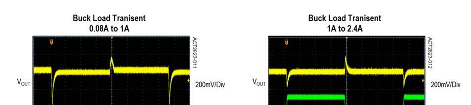
21 Typical Performance Characteristics (Schematic as shown in Figure 8, Ta=25 C unless otherwise specified) 21

22 22
23 23
24 PACKAGE OUTLINE AND DIMENSIONS QFN55-40 PIN #1 DOT BY MARKING Top View D D/2 SYMBOL DIMENSION IN MIL- LIMETERS DIMENSION IN INCHES MIN MAX MIN MAX A E/2 A E A REF REF b D E L Bottom View b D E e 0.400TYP TYP L e D1 k MIN MIN E1 k A3 A A1 Active-Semi, Inc. reserves the right to modify the circuitry or specifications without notice. Users should evaluate each product to make sure that it is suitable for their applications. Active-Semi products are not intended or authorized for use as critical components in life-support devices or systems. Active-Semi, Inc. does not assume any liability arising out of the use of any product or circuit described in this datasheet, nor does it convey any patent license. Active-Semi and its logo are trademarks of Active-Semi, Inc. For more information on this and other products, contact sales@active-semi.com or visit is a registered trademark of Active-Semi. 24
25 REVISION HISTORY REVISION DATE DESCRIPTION 1 05-DEC-2016 General clarification of device functionality. No IC functional changes or EC table changes from Rev 0 to Rev 1 25
ACT V/3.4A Dual Cell Battery Power Manager FEATURES APPLICATIONS GENERAL DESCRIPTION. Rev 3, Apr
 5V/3.4A Dual Cell Battery Power Manager FEATURES Dedicated Single-chip Integrated Battery Power Manager Dual Cell Battery Charger with Cell Balancing Management Auto Detection support USB BC1.2, Chinese
ACT V/1.5A Backup Battery Pack Manager FEATURES APPLICATIONS GENERAL DESCRIPTION. Rev 0, 06-Nov-13 Product Brief
 0 200 400 600 800 1000 1400 1200 5.5 FEATURES Dedicated Single Chip Solution for Mobile Power With Minimal Component Count 5V/1.5A Constant Output Current in Boost Mode 1.5A Switching Charger Programmable
ACE4108 Max.2A Li-ion Switching Charger IC
 Description The ACE4108 is a 2A Li-Ion battery switching charger intended for 12V. Low power dissipation, an internal MOSFET and its compact package with minimum external components requirement makes the
2A Switch-Mode Li-Ion Battery Charger
 2A Switch-Mode Li-Ion Battery Charger General Description The is a highly integrated switch-mode Li-Ion Battery Charger. With few external components, is well suited for a wide range of portable applications.
HM5061 Max.1.6A Li-ion Switching Charger IC
 Max.1.6A Li-ion Switching Charger IC DESCRIPTION The HM5061 is a 1.6A Li-Ion battery switching charger intended for 5V adapters. Low power dissipation, an internal MOSFET and its compact package with minimum
FEATURES DESCRIPTION APPLICATIONS TYPICAL APPLICATION PIN OUT & MARKING. Max.2A Li-ion Switching Charger IC
 DESCRIPTION The is a 2A Li-Ion battery switching charger intended for 5V adapters. Low power dissipation, an internal MOSFET and its compact package with minimum external components requirement makes the
3A Switching Charger, 2.4A Boost and Fuel Gauge in One ESOP8 with Single Inductor
 3A Switching Charger, 2.4A Boost and Fuel Gauge in One ESOP8 with Single Inductor DESCRIPTION ETA9740 is a switching Li-Ion battery charger capable of delivering up to 3A of charging current to the battery
BL8578 DESCRIPTION FEATURES APPLICATIONS PIN OUT & MARKING TYPICAL APPLICATION. Max.2A Li-ion Switching Charger IC
 1 2 3 4 6 7 8 9 10 1 2 BG I LLHYW 3 BG LLHYW 4 6 7 8 9 10 DESCRIPTION The is a 2A Li-Ion battery switching charger intended for V adapters. Low power dissipation, an internal MOSFET and its compact package
Lithium Ion Battery Charger for Solar-Powered Systems
 Lithium Ion Battery Charger for Solar-Powered Systems General Description: The is a complete constant-current /constant voltage linear charger for single cell Li-ion and Li Polymer rechargeable batteries.
XA4202. The XA4202 is available in the 8-lead SO Package. Charging Docks Handheld Instruments Portable Computers.
 Standalone Li-Lon Switch Mode Battery Charger Features Input Supply Range: 4.7V-6V High Efficiency Current Mode PWM Controller End - Charge - Current Detection Output Constant Switching Frequency for Minimum
A4063. AiT Semiconductor Inc. APPLICATION ORDERING INFORMATION TYPICAL APPLICATION
 DESCRIPTION The is a 2A Li-Ion battery switching charger intended for 5V adapters. Low power dissipation, an internal MOSFET and its compact package with minimum external components requirement makes the
COTAG GENERAL DESCRIPTION
 GENERAL DESCRIPTION The YF8036 is a highly integrated Li-ion battery linear charging management device targeted at space limited portable applications. The YF8036 offers an integrated MOSFET and current
The XA4203 is available in the SOP-8L package. Charging Docks Handheld Instruments Portable Computers
 Standalone Li-Ion Switch Mode Battery Charger Features Input Supply Range: 9V-16V End - Charge - Current Detection Output Constant Switching Frequency for Minimum Noise Automatic Battery Recharge Automatic
1.2A Single-chip Li-ion and Li-POL Charge
 1.2A Single-chip Li-ion and Li-POL Charge General Description The LP28012 is a complete constant-current/ constant voltage linear charger for single cell lithium-ion batteries. Its ESOP8 package and low
5A Synchronous Buck Li-ion Charger With Adapter Adaptive
 5A Synchronous Buck Li-ion Charger With Adapter Adaptive General Description The is a 5A Li-Ion battery charger intended for 4.4~14 wall adapters. It utilizes a high efficiency synchronous buck converter
800mA Linear Li-Ion Battery Charger with Protection of Reverse Connection of Battery
 800mA Linear Li-Ion Battery Charger with Protection of Reverse Connection of Battery General Description The is a complete constant-current/constant- voltage linear charger for single cell lithium-ion
HX6038 HX
 HX1001 Advanced Linear Charge Management Controller Features Preset 8.4V Charge Voltage with 1% Accuracy Input Voltage: 9V-16V Pre-Charging, the Charge Current is Programmable Charge Current Up to 1A adjustable
1A Single Chip Li-Ion and Li-Polymer Charger
 1A Single Chip Li-Ion and Li-Polymer Charger General Description The LP28055 is a complete constant-current/ constant voltage linear charger for single cell lithium-ion battery. Its ESOP8 package and low
ChipLead Technology VAS A USB/Adapter Switching Charger. Features. General Description. Applications
 2.5A USB/Adapter Switching Charger General Description The is a highly-integrated switch-mode battery charge management device for 1 cell Li-Ion and Li-polymer batteries in a wide range of tablet and other
2A Synchronous Buck Li-ion Charger
 2A Synchronous Buck Li-ion Charger General Description The is a 5A Li-Ion battery charger intended for 4.4V~14V wall adapters. It utilizes a high efficiency synchronous buck converter topology to reduce
Standalone Linear Li-Ion Battery Charger with Thermal Regulation
 HM4056 Standalone Linear Li-Ion Battery Charger with Thermal Regulation FEATURES DESCRIPTION Programmable Charge Current up to 1A No MOSFET, Sense Resistor or Blocking Diode Required Constant-Current/Constant-Voltage
800mA Linear Li-Ion Battery Charger
 800mA Linear Li-Ion Battery Charger General Description The is a complete constant-current/constant- voltage linear charger for single cell lithium-ion batteries. Its package and low external component
1.2A Single-chip Li-ion and Li-POL Charge
 1.2A Single-chip Li-ion and Li-POL Charge General Description The is a complete constant-current / constant-voltage linear charger for single cell lithium-ion batteries. Its ESOP-8 package and low external
2 cell Li-ion Battery Charge from 3V~12V
 2 cell Li-ion Battery Charge from 3V~12V General Description The is a complete constant-current/ constant voltage switching charger for multi cell lithium-ion batteries. Boost+Linear charger work with
PT8A mA Li-ion/Polymer Battery Charger
 Features A Constant-Current / Constant-Voltage Linear Charger for Single-Cell Li-ion/Polymer Batteries Integrated Pass Element and Current Sensor Highly-Integrated, Requiring No External FETs or Blocking
CONSONANCE CN3051A/CN3052A. 500mA USB-Compatible Lithium Ion Battery Charger. General Description: Features: Pin Assignment.
 CONSONANCE 500mA USB-Compatible Lithium Ion Battery Charger CN3051A/CN3052A General Description: The CN3051A/CN3052A is a complete constant-current /constant voltage linear charger for single cell Li-ion
DT V 800mA Standalone Linear Li-ion Battery Charger FEATURES GENERAL DESCRIPTION APPLICATIONS ORDER INFORMATION
 GENERAL DESCRIPTION The DT7102 is a highly integrated 5V 800mA Li-ion battery linear charging management device with standby indicator output. The DT7102 charges a battery in three phases: trickle charging,
1A/800mA Standalone Linear Li-Ion Battery Charger. Features
 1A/800mA Standalone Linear Li-Ion Battery Charger General Description The is a complete constant-current/constant- voltage linear charger for single cell lithium-ion batteries. Its ESOP8 package and low
800mA Lithium Ion Battery Linear Charger
 GENERAL DESCRIPTION is a complete CC/CV linear charger for single cell lithium-ion batteries. it is specifically designed to work within USB power Specifications. No external sense resistor is needed and
SGM4056 High Input Voltage Charger
 GENERAL DESCRIPTION The SGM456 is a cost-effective, fully integrated high input voltage single-cell Li-ion battery charger. The charger uses a CC/CV charge profile required by Li-ion battery. The charger
CONSONANCE. 1A LiFePO4 Battery Charger CN3058E. Features: General Description: Applications: Pin Assignment
 A LiFePO4 Battery Charger CN3058E General Description: The CN3058E is a complete constant-current /constant voltage linear charger for single cell LiFePO4 rechargeable batteries. The device contains an
CONSONANCE. 1A Nickel-Metal Hydride Battery Charger IC CN3085. General Description: Features: Pin Assignment. Applications:
 A Nickel-Metal Hydride Battery Charger IC CN3085 General Description: CN3085 is a charger IC for single to four cell Nickel Metal Hydride (NiMH) batteries. The device contains an on-chip power MOSFET and
IP5209. Fully-integrated power bank System-On-Chip with 2.1A charger, 2.4A boost converter and DCP support. 1 Features. 2 Applications.
 Fully-integrated power bank System-On-Chip with 2.1A charger, 2.4A boost converter and DCP support 1 Features Synchronous switching charger and synchronous boost converter 2.1A synchronous switching charger,
DT V 1A Standalone Linear Li-ion Battery Charger FEATURES GENERAL DESCRIPTION APPLICATIONS ORDER INFORMATION
 GENERAL DESCRIPTION The DT7115 is a highly integrated 5V 1A Li-ion battery linear charging management device. The DT7115 charges a battery in three phases: trickle charging, constant current, and constant
Package: RN: SOT23-5 TRN: TSOT23-5 Features: P: Standard (default, lead free) C: Customized. 1uF
 C: Customized. 1uF") FEATURES Programmable Charge Current Up to 8mA No MOSFET, Sense Resistor or Blocking Diode Required Preset 4.2V Charge Voltage with ±1% Accuracy Charge Current Monitor Output for Gas Gauging Thermal Regulation
FEATURES Programmable Charge Current Up to 8mA No MOSFET, Sense Resistor or Blocking Diode Required Preset 4.2V Charge Voltage with ±1% Accuracy Charge Current Monitor Output for Gas Gauging Thermal Regulation
CE3152 Series. Standalone Linear LiFePO4 battery charger with Thermal Regulation INTRODUCTION: FEATURES: APPLICATIONS: PIN CONFIGURATION:
 Standalone Linear LiFePO battery charger with Thermal Regulation Series INTRODUCTION: The is a complete constantcurrent constantvoltage linear charger for single cell LiFePO batteries. It s SOT package
800mA Standalone Linear Li-Ion Battery Charger with Dual LED Display
 800mA Standalone Linear Li-Ion Battery Charger with Dual LED Display General Description The is a complete constant-current/constant- voltage linear charger for single cell lithium-ion batteries. Its SOT
2.5A, 3MHz Switching Charger with Dynamic Power Path in 8-pin ESOP SYS 2.2K STAT. 2A Switching Charger with Minimum Component Count
 .5A, 3MHz Switching Charger with Dynamic Power Path in 8-pin ESOP DESCRIPTION ETA6 is a switching Li-Ion battery charger with dynamic power-path control and input current limiting. When a battery is connected,
PT1054 Lithium Ion Battery Linear Charger
 GENERAL DESCRIPTION PT1054 is a complete CC/CV linear charger f or single cell lithium-ion batteries. it is specifically designed to work within USB power Specifications. No external sense resistor is
XA4217. Preset 8.4V Charge Voltage with 1% Accuracy
 High Accuracy Linear Li-Lon Battery Charger Features Preset 8.4V Charge Voltage with 1% Accuracy Input Voltage:9-10V DC Pre-Charging, the Charge Current is Programmable Charge Current Up to 1A adjustable
HM8202. The HM8202 is available in the SOP-8L package. Charging Docks Handheld Instruments Portable Computers
 Standalone Li-Ion Switch Mode Battery Charger Features Input Supply Range: 9V ~ 14V End-Charge-Current Detection Output Constant Switching Frequency for Minimum Noise Automatic Battery Recharge Automatic
500mA Standalone Linear Li-Ion Battery Charger. Features
 500mA Standalone Linear LiIon Battery Charger General Description The is a complete constantcurrent/constant voltage linear charger for single cell lithium ion batteries. Its SOT235 package and low external
SC61A05. Standalone Linear Li-Lon Battery Charger. With Thermal Regulation. Features. Description. Applications
 Standalone Linear Li-Lon Battery Charger With Thermal Regulation Description The SC61A05 is a single-cell lithium-ion battery charger using a constant-current/ constant-voltage algorithm. It can deliver
Fully integrated constant current/constant voltage Li-ion battery charger
 Description The ACE4054 is a single cell, fully integrated constant current (CC) / constant voltage (CV) Li-ion battery charger. Its compact package with minimum external components requirement makes the
Rev1.0 UCT V 1A Standalone Linear Li-ion Battery Charger GENERAL DESCRIPTION FEATURES APPLICATIONS
 5V 1A Standalone Linear Li-ion Battery Charger GENERAL DESCRIPTION The UCT3146 is a highly integrated 5V 1A Li-ion battery linear charging management device. The UCT3146 charges a battery in three phases:
ACE4054C. 500mA/1.5A Standalone Linear Li-Ion Battery Charge
 Description The ACE4054C is a single cell, fully integrated constant current (CC)/ constant voltage (CV) Li-ion battery charger. Its compact package with minimum external components requirement makes the
800mA Lithium Ion Battery Linear Charger
 800mA Lithium Ion Battery Linear Charger General Description is a complete constant-current/constant voltage linear charger for single cell lithium-ion batteries. Furthermore the is specifically designed
ME4054 Standalone Linear Li-Ion Battery Charger with Thermal Regulation in ThinSOT ME4054
 Standalone Linear Li-Ion Battery Charger with Thermal Regulation in ThinSOT Standalone Linear Li-Ion Battery Charger in ThinSOT -4.2V DESCRIPTION is a constant-current/constant-voltage linear charger for
CE3211 Series. Standalone 1A Linear Lithium Battery Charger With Thermal Regulation INTRODUCTION: FEATURES: APPLICATIONS:
 Standalone 1A Linear Lithium Battery Charger With Thermal Regulation INTRODUCTION: The CE3211 is a complete constant-current/ constant-voltage linear charger for single cell lithium rechargeable battery.
CONSONANCE CN mA USB-Compatible Lithium Battery Charger. General Description: Features: Applications: Pin Assignment
 CONSONANCE 500mA USB-Compatible Lithium Battery Charger CN306 General Description: The CN306 is a complete constant-current /constant voltage linear charger for single cell lithium rechargeable battery.
ETA A, 3MHz Switching Charger with Dynamic Power Path Management
 2.5A, 3MHz Switching Charger with Dynamic Power Path Management DESCRIPTION ETA6003 is a switching Li-Ion battery charger with dynamic power-path control and input current limiting. When a battery is connected,
1A is compatible with the USB interface, linear battery management chip
 1A is compatible with the USB interface, linear battery management chip General Description The is a constant- current / constant- voltage charger circuit for single cell lithium-ion batteries. The device
1A Linear Li-Ion Battery Charger in SOP8
 1A Linear Li-Ion Battery Charger in SOP8 FP8103 General Description The FP8103 is a standalone linear Li-ion battery charger with exposed pad SOP8 package. With few external components, FP8103 is well
300mA,Ultra-low noise, Small Package Ultra-Fast CMOS LDO Regulator
 2 GND Preliminary Datasheet 300mA,Ultra-low noise, Small Package Ultra-Fast CMOS LDO Regulator General Description The is designed for portable RF and wireless applications with demanding performance and
LM3621 Single Cell Lithium-Ion Battery Charger Controller
 Single Cell Lithium-Ion Battery Charger Controller General Description The is a full function constant voltage, constant current (CVCC) lithium-ion (Li+) battery charger controller. It provides 1% regulation
1A Single Chip Li-Ion and Li-Polymer Charger
 1A Single Chip Li-Ion and Li-Polymer Charger General Description The is a complete constant-current / constant-voltage linear charger for single cell lithium-ion battery. Its TDFN-10 package and low external
1A Linear Li-Ion Battery Charger in SOP8/MSOP8
 1A Linear Li-Ion Battery Charger in SOP8/MSOP8 FP8102 General Description The FP8102 is a standalone linear Li-ion battery charger with exposed pad SOP8/MSOP8 package. With few external components, FP8102
Silvertel. Ag Features. Multi-Stage Charging. Battery Reversal Protection. Reduced Power Consumption. Wide DC or AC Input Voltage Range
 Silvertel V1.1 October 2012 Pb 1 Features Multi-Stage Charging Battery Reversal Protection Reduced Power Consumption Wide DC or AC Input Voltage Range High Efficiency DC-DC Converter Programmable Charge
CE3151 Series. Standalone Linear Li-Ion Battery Charger with Thermal Regulation
 Standalone Linear Li-Ion Battery Charger with Thermal Regulation INTRODUCTION: The CE3151 is a complete constant-current/ constant voltage linear charger for single cell lithium-ion batteries. Its SOT
MP V, 1A, Li-lon, Linear Battery Charger with 10mA High Voltage LDO
 The Future of Analog IC Technology DESCRIPTION The MP2631 is a linear, high performance single cell Li-Ion or Li-Polymer battery charger with 1mA LDO. By integrating high voltage input protection into
DIO5538B 5~100mA,Single Li-ion Battery Charger
 5~100mA,Single Li-ion Battery Charger Rev 1.1 Features Broad Programmable Charging Current: 5~100mA Over-Temperature Protection Under Voltage Lockout Protection Reverse current protection between BAT and
500mA Linear Li-Ion Battery Charger in SOT23
 500mA Linear Li-Ion Battery Charger in SOT23 General Description The is a standalone linear Li-ion battery charger with exposed pad SOT23 package. With few external components, is well suited for a wide
HP420X. 5A, High Efficiency POL Module GENERAL DESCRIPTION: FEATURES: APPLICATIONS: TYPICAL APPLICATION CIRCUIT & PACKAGE SIZE:
 FEATURES: High Power Density Power Module 5A Maximum Load Input Voltage Range from 9.0V to 40.0V Output Voltage Range from 1.0V to 5.0V Excellent Thermal Performance 94% Peak Efficiency Enable Function
VS6102 Standalone Linear Lithium Battery Charger
 General Description VS6102 is a complete constant-current & constant voltage linear charger for single cell lithium-ion batteries. Its SOT-23 package and low external component count make VS6102 ideally
3.5A Synchronous Buck Li-ion Charger With Intelligent Path Management Adapter Adaptive and OTG
 3.5A Synchronous Buck Li-ion Charger With Intelligent Path Management Adapter Adaptive and OTG General Description The is a 3.5A Li-Ion battery charger intended for 4.4V~14V wall adapters. It utilizes
Features. General Description. Component List
 General Description The MAX17502F evaluation kit (EV kit) provides a proven design to evaluate the MAX17502F high-efficiency, highvoltage, synchronous step-down DC-DC converter. The EV kit uses the device
A4059. AiT Semiconductor Inc. Available in PSOP8 Package APPLICATION ORDERING INFORMATION
 STANDALONE LINEAR LI-ION BATTERY CHARGER WITH THERMAL REGULATION DESCRIPTION The is charging management circuit that can be programmed through an external resistor constant current / constant voltage charging.
EUP8075/8079. Preliminary. USB-Compliant Li-Ion Battery Charger Integrated with System Power-Path Management FEATURES DESCRIPTION APPLICATION
 Preliminary EUP8075/8079 USB-Compliant Li-Ion Battery Charger Integrated with System Power-Path Management DESCRIPTION The EUP807X series of devices are highly integrated Li-ion linear chargers and system
ACT3780. ActivePath TM Battery Charger
 ActivePath TM Battery Charger FEATURES ActivePath TM System Power Selection of Best Available Input Supply 50m Battery Switch for Highest Efficiency Dynamic Control of Charging Current Allowing System
Techcode. Features. General Description. Applications. Package Types DATASHEET
 General Description Features The TD9054 is a complete constant current/constant voltage linear charger for single cell lithium ion batteries. Its SOT23 5 package and low external component count make the
1A Linear Li+ Battery Chargers with Integrated Pass FET and Thermal Regulation in 2mm x 2mm TDFN
 19-3670; Rev 0; 4/05 EVALUATION KIT AVAILABLE 1A Linear Li+ Battery Chargers with Integrated Pass General Description The intelligent, stand-alone constant-current/constant-voltage (CCCV), thermally regulated
ETA mA Fully Integrated Linear Charger for 1 Cell Li-ion Battery APPLICATIONS ORDERING INFORMATION TYPICAL APPLICATION
 800mA Fully Integrated Linear Charger for 1 Cell Li-ion Battery DESCRIPTION is a single cell, fully integrated constant current (CC)/constant voltage (CV) Li-ion battery charger. Its compact package with
DIO5518D 300mA,Single Li-ion Battery Charger
 300mA,Single Li-ion Battery Charger Rev.0 Features Programmable Charge Current Up to 300mA Over-Temperature Protection Under oltage Lockout Protection Over oltage Lockout Protection Reverse current protection
FEATURES. Charging. - High Voltage Chemistry Support: up to 4.35V. Others
 HM5B GENERAL DESCRIPTION The HM5B series of devices are highly integrated Li-Ion and Li-Pol linear chargers targeted at small capacity battery for portable applications. It is a complete constant-current/
XT2059. Programmable voltage and current linear battery management chip. General Description. Applications. Package. Features
 Programmable voltage and current linear battery management chip General Description The is charging management circuit that can be programmed through an external resistor constant current / constant voltage
High Efficiency POL Module
 High Efficiency POL Module MPX24AD05-TU FEATURES: High Power Density Power Module 5A Maximum Load Input Voltage Range from 9.0V to 40.0V Output Voltage Range from 1.0V to 5.0V Excellent Thermal Performance
General Description. Features. Component List. Component Suppliers
 General Description The MAX5062A evaluation kit (EV kit) is a fully assembled and tested circuit board that demonstrates the performance of the MAX5062A 60V, 300mA ultra-small, high-efficiency, synchronous
Model Number Output Voltage Output Amps Input Range Max. Iin FL Efficiency Max Output Power
 Small 2.32 x 0.9 x 0.37 Size Constant Frequency High Typical Efficiency of 90% (12Vout) Low Output Noise 18 to 60VDC Input Voltage Range Output Over Voltage Protection Current Limit/Short Circuit Protection
Evaluate: MAX17502E in TDFN Package. MAX17502E Evaluation Kit. General Description. Features. Component List
 General Description The MAX17502E evaluation kit (EV kit) provides a proven design to evaluate the MAX17502E high-efficiency, highvoltage, synchronous step-down DC-DC converter. The EV kit uses this device
Techcode. General Description. Features. Applications. Package Types DATASHEET. 1A Standalone Linear Li-lon Battery Charger with Thermal Regulation
 General Description Features The is a complete constant current/constant voltage linear charger for single cell lithium ion batteries. Its SOP package and low external component count make the ideally
Output Voltage Current. Input Current Ripple. Efficiency (typ.) Load VDC VDC ma ma ma(typ.) ma(typ.) ma(typ.) μf % 2.
 Load VDC VDC ma ma ma(typ.) ma(typ.) ma(typ.) μf % 2.") FEATURES Industrial Standard 2" X 1" Package Wide 2:1 Input Voltage Range Fully Regulated Output Voltage High Efficiency up to 88% I/O Isolation 1500 VDC Operating Ambient Temp. Range -40 to 85 Overload
FEATURES Industrial Standard 2" X 1" Package Wide 2:1 Input Voltage Range Fully Regulated Output Voltage High Efficiency up to 88% I/O Isolation 1500 VDC Operating Ambient Temp. Range -40 to 85 Overload
Li-ion/Li Polymer Battery Charger. Features
 General Description The is a highly-integrated battery charger for single-cell Li-ion or Li-polymer batteries capable of operating with an input voltage reached 2.5V. It is a complete charger device designed
EB Series Eighth - Brick Up to 100 Watt DC-DC Converter
 FEATURES DOSA Standard Form, Fit & Function Industry standard 1/8th brick footprint 4:1 input voltage range: 9-36 or 18 75Vin ROHS II Directive 2011/65/EU Compliant No minimum load required -40 0 C to
Silvertel. Ag Features. Multi-Stage Charging. Battery Reversal Protection. Reduced Power Consumption. Wide DC or AC Input Voltage Range
 Silvertel V1.3 October 2009 Datasheet Intelligent Pb 1 Features Multi-Stage Charging Battery Reversal Protection Reduced Power Consumption Wide DC or AC Input Voltage Range High Efficiency DC-DC Converter
QUICK START GUIDE FOR DEMONSTRATION CIRCUIT 1020 HIGH EFFICIENCY USB POWER MANAGER + TRIPLE STEP-DOWN DC/DC LTC3555
 DESCRIPTION Demonstration Circuit 1020 is a High Efficiency USB Power Manager + Three Step-Down DC/DC Converters featuring the LTC 3555. The LTC 3555 is a highly integrated power management and battery
STBC03. Li-Ion linear battery charger with LDO and load switches. Datasheet. Features. Applications. Description
 Datasheet Li-Ion linear battery charger with LDO and load switches Features Charges single-cell Li-Ion batteries with CC/CV algorithm and charge termination Fast charge current up to 650 ma adjustable
MAX1757/MAX1758 Evaluation Kits
 9-86; Rev 0; 0/00 MAX757/MAX758 Evaluation Kits General Description The MAX757/MAX758 evaluation kits (EV kits) are assembled and tested PC boards that implement a step-down, switching lithium-ion (Li+)
RT9525. Linear Single Cell Li-Ion Battery Charger with Auto Power Path. General Description. Features. Applications. Ordering Information
 RT9525 Linear Single Cell Li-Ion Battery Charger with Auto Power Path General Description The RT9525 is an integrated single cell Li-ion battery charger with Auto Power Path Management (APPM). No external
S24SP series 40W Single Output DC/DC Converter
 4W Single Output DC/DC Converter FEATURES Efficiency up to 92.8% Wide input range, 9V-36V Package with Industry Standard Pinout Package Dimension: Without heat sink 5.8 x25.4 x1.2mm (2. x1. x.4 ) With
MJWI20 SERIES FEATURES PRODUCT OVERVIEW. DC/DC Converter 20W, Highest Power Density MINMAX MJWI20 Series
 DC/DC 2W, Highest Power Density MINMAX MJWI2 Series MJWI2 SERIES DC/DC CONVERTER 2W, Highest Power Density FEATURES Smallest Encapsulated 2W! Package Size 1. x1. x.4 Ultra-wide 4:1 Input Range Very high
150 WATT HEW SINGLE SERIES DC/DC CONVERTERS
 Features Description The 4:1 Input Voltage 150 W single HEW Series of DC/DC converters provide precisely regulated dc outputs. The output voltage is fully isolated from the input, allowing the output to
WATT MBH SERIES DC/DC CONVERTERS
 Features Delivers up to 2100 Watts Efficiency up to 97 Groundbreaking low profile compact 9.0 L x 6.5 W x 1.25 H package Only 3.3 lbs No minimum load required Fixed frequency operation at 400 khz Fully
FEATURES TYPICAL APPLICATIO. LTC4062 Standalone Linear Li-Ion Battery Charger with Micropower Comparator DESCRIPTIO APPLICATIO S
 FEATURES Charge Current Programmable Up to 1A Charges Single-Cell Li-Ion Batteries Directly from USB Port Preset Float Voltage with ±.35% Accuracy Micropower Comparator for Battery Monitoring Thermal Regulation
IND065BLV Hornet: Non-Isolated DC-DC Voltage Regulator Modules
 IND065BLV Hornet: Non-Isolated DC-DC Voltage Regulator Modules 12Vdc input; 16Vdc to 34Vdc output; 65W Max Power Vin+ VIN VOUT PGOOD MODULE Vout+ Applications Industrial Equipment Control Boards Test Equipment
AAT A/1.0A USB Port/Adapter Lithium-Ion/Polymer Battery Charger
 General Description Features BatteryManager The AAT3689 BatteryManager is a highly integrated single cell lithium-ion/polymer battery charger IC designed to operate with port and AC adapter inputs. It
(typ.) (Range) ±18 330# 89 MPW MPW
 (Range) ±18 330# 89 MPW MPW") DC/DC 30W, Single & Dual Output FEATURES 2 x 1.6 x 0.4 Metal Package Ultra-wide 4:1 Input Range Operating Temp. Range 40 C to 80 C Short Circuit Protection I/O-isolation 1500 VDC Input Filter meets EN
DC/DC 30W, Single & Dual Output FEATURES 2 x 1.6 x 0.4 Metal Package Ultra-wide 4:1 Input Range Operating Temp. Range 40 C to 80 C Short Circuit Protection I/O-isolation 1500 VDC Input Filter meets EN
1A Charge+ 3A Synchronous Boost PMIC
 1A Charge 3A Synchronous Boost PMIC General Description The is a PMIC,which has 1ch Charger and 1ch Synchronous Boost Converter with ESOP8 and TDFN10 package. Its charger is a complete constantcurrent
+Denotes lead(pb)-free and RoHS compliant. JU1 JU4 4
-free and RoHS compliant. JU1 JU4 4") 19-4381; Rev 0; 11/08 General Description The MAX8844Z evaluation kit (EV kit) is a fully assembled and tested PCB for evaluating the MAX8844Z/ MAX8844Y 28V linear Li+ battery chargers. The MAX8844Z EV
19-4381; Rev 0; 11/08 General Description The MAX8844Z evaluation kit (EV kit) is a fully assembled and tested PCB for evaluating the MAX8844Z/ MAX8844Y 28V linear Li+ battery chargers. The MAX8844Z EV
ST3S01PHD BATTERY CHARGE I.C.
 BATTERY CHARGE I.C. DEDICATED I.C. FOR 1 LI-ION CELL OR 3 NI-MH CELLS 5 DIFFERENT OPERATING MODES 150 ma PRECHARGE CURRENT VERY LOW DROP CHARGE SWITCH (130mV @ 800mA) VERY LOW DROP REVERSE SWITCH (130mV
Ag Features. Multi-Stage Charging. Solar Panel or DC Input. Maximum Power Point Tracking (MPPT) Very Low Power Consumption
 Very Low Power Consumption") Datasheet Ag103 Intelligent Sealed Lead Acid Solar Battery Charger Module Pb 1 Features Multi-Stage Charging Solar Panel or DC Input Maximum Power Point Tracking (MPPT) Very Low Power Consumption Wide
Datasheet Ag103 Intelligent Sealed Lead Acid Solar Battery Charger Module Pb 1 Features Multi-Stage Charging Solar Panel or DC Input Maximum Power Point Tracking (MPPT) Very Low Power Consumption Wide