Wind Power Inverter WINDY BOY 3600TL / 5000TL
|
|
|
- Walter Oliver
- 5 years ago
- Views:
Transcription

1 Wind Power Inverter WINDY BOY 3600TL / 5000TL Installation Guide WB36TL_50TL-IEN IMEN-WB36_50TL Version 1.1 EN
2
3 SMA Solar Technology AG Table of Contents Table of Contents 1 Notes on this Manual Validity Target Group Additional Information Symbols Used Safety Appropriate Usage Safety Precautions Explanation of Symbols Symbols on the Inverter Symbols on the Type Plate Unpacking Packing List Identifying the Inverter Mounting Safety Selecting the Mounting Location Mounting the Inverter with the Wall Mounting Bracket Mounting the inverter with a top hat rail Electrical Connection Safety Overview of the Connection Area Connection to the Power Distribution Grid (AC) Conditions for the AC Connection Connecting the Inverter to the Power Distribution Grid (AC) Additional Grounding of the Housing Installation Guide WB36TL_50TL-IEN
4 Table of Contents SMA Solar Technology AG 5.4 Connecting Windy Boy Protection Box (DC) Conditions for the DC Connection Assembling the DC Plug Connector Opening the DC Plug Connector Connecting the Windy Boy Protection Box (DC) Setting the Country Standard and Display Language Checking the Country Standard Setting the Country Standard and Language using Rotary Switches Communication Multi-function relay Communication module Polynomial Characteristic Curve Initial start-up Self-test according to DK 5940, ED. 2.2 (for Italy only) Starting the Self-Test by Tapping Test Sequence Interruption of the Self-Test Restarting the Self-Test Display Messages during Initialization Operating Conditions of the Inverter Disconnecting the Inverter Safety Disconnect the device from voltage sources Restarting the system Maintenance and Cleaning Checking Heat Dissipation Cleaning the Fan Checking the Fans Checking the Electronic Solar Switch (ESS) for Wear WB36TL_50TL-IEN Installation Guide
5 SMA Solar Technology AG Table of Contents 10 Slot for SD card Messages Event messages Error Messages Troubleshooting Checking the Small Wind Turbine System for a Ground Fault Checking the Functioning of the Varistors Decommissioning Dismantling the Inverter Packing the Inverter Storing the Inverter Disposing of the Inverter Technical Data Windy Boy 3600TL Windy Boy 5000TL Accessories Contact Installation Guide WB36TL_50TL-IEN
6 Table of Contents SMA Solar Technology AG 6 WB36TL_50TL-IEN Installation Guide
7 SMA Solar Technology AG Notes on this Manual 1 Notes on this Manual This manual describes the assembly, installation, commissioning and maintenance of the following SMA inverters: Windy Boy 3600TL (WB 3600TL-20) Windy Boy 5000TL (WB 5000TL-20) Store this manual where it can be accessed at all times. 1.1 Validity This manual is valid for the Windy Boy 3600TL and Windy Boy 5000TL. 1.2 Target Group This manual is for qualified personnel. The tasks described in this manual may be performed by qualified electrical technicians only. 1.3 Additional Information You will find further information on special topics such as designing a line circuit breaker or the description of the operating parameters in the download area at Refer to the user manual for detailed information on operating the inverter. Installation Guide WB36TL_50TL-IEN
8 Notes on this Manual SMA Solar Technology AG 1.4 Symbols Used The following types of safety warnings and general information are used in this manual: DANGER! "DANGER" indicates a hazardous situation which, if not avoided, will result in death or serious injury. WARNING! "WARNING" indicates a hazardous situation which, if not avoided, could result in death or serious injury. CAUTION! "CAUTION" indicates a hazardous situation which, if not avoided, could result in minor or moderate injury. NOTICE! "NOTICE" indicates a situation that can result in property damage if not avoided. Information Information provides tips that are valuable for the optimal installation and operation of your product. This symbol indicates the result of an action. 8 WB36TL_50TL-IEN Installation Guide
9 SMA Solar Technology AG Safety 2 Safety 2.1 Appropriate Usage The Windy Boy is a wind power inverter, which converts rectified current of a small wind turbine system into AC current and feeds this energy into the power distribution grid, domestic grid or the Sunny Island system. Principle of a small wind turbine system with Windy Boy Furthermore, the Windy Boy can be used as an inverter for power conversion units based on the permanent magnet generators (hydro power systems, combined heat and power plant, diesel generator, etc.). The manufacturer of the small wind turbine system or the generators should have his system set up for operation with the Windy Boy (see also the Windy Boy planning guidelines in the download area at SMA Solar Technology AG recommends to operate Windy Boy and a small wind turbine system without neutral grounding. When designing the system, ensure that the permitted operating range of all components is maintained at all times. Also use appropriate protective measures to make sure that the maximum permissible input voltage of the inverter is not exceeded. Use of the WBP-Box Windy Boy Protection Box by SMA Solar Technology AG is obligatory. Do not use the Windy Boy for purposes other than those described here. Alternative uses, modifications to the Windy Boy or the installation of components not expressly recommended or sold by SMA Solar Technology AG void the warranty claims and operation permission. Installation Guide WB36TL_50TL-IEN
10 Safety SMA Solar Technology AG 2.2 Safety Precautions DANGER! Danger to life due to high voltages in the inverter. All work on the inverter may be carried out by qualified personnel only. The appliance is not to be used by children or persons with reduced physical, sensory or mental capabilities, or lack of experience and knowledge, unless they have been given supervision or instruction. Children should be supervised to ensure that they do not play with the appliance. CAUTION! Danger of burn injuries due to hot enclosure parts. During operation, the upper lid of the enclosure and the enclosure body may become hot. Only touch the lower enclosure lid during operation. CAUTION! Possible damage to health as a result of the effects of radiation. Do not stay closer than 20 cm to the inverter for any length of time. 10 WB36TL_50TL-IEN Installation Guide
11 SMA Solar Technology AG Safety 2.3 Explanation of Symbols This section contains an explanation of all symbols found on the inverter and type label Symbols on the Inverter Symbol Explanation Operation Display. Indicates the operation condition of the inverter. An error has occurred. Read the installation guide and the user manual to remedy the malfunction. Bluetooth Wireless Technology. Shows the status of Bluetooth communication. Tap to switch on the display light and switch to the next display message. When the Electronic Solar Switch is plugged in, the DC circuit is closed. To interrupt the DC circuit and disconnect the inverter securely under load, you must release the inverter as described in section 7.2 Disconnect the device from voltage sources (page 59). Installation Guide WB36TL_50TL-IEN
12 Safety SMA Solar Technology AG Symbols on the Type Plate Symbol Explanation Warning: dangerous electrical voltage. The inverter operates at high voltages. Any work on and at the inverter must be carried out by a qualified electrician only. Beware of hot surface. The inverter can become hot during operation. Avoid contact during operation. Observe all documentation that accompanies the inverter. The inverter must not be disposed of together with the household waste. For more information on disposal, see section 13.4 Disposing of the Inverter (page 84). CE mark. The inverter complies with the requirements of the applicable EC guidelines. The inverter is transformerless. Direct current (DC). Alternating Current (AC). Protection rating IP54. The inverter is protected against dust deposits in the interior and against splashes of water from all angles. RAL quality mark for solar products. The inverter complies with the requirements of the German Institute for Quality Assurance and Labeling. Device class label. The inverter is equipped with a wireless component that complies with the harmonized standards. 12 WB36TL_50TL-IEN Installation Guide


13 SMA Solar Technology AG Unpacking 3 Unpacking 3.1 Packing List Check the delivery for completeness and any visible external damage. Contact your dealer if anything is damaged or missing. Object Number Description A 1 Inverter B 1 Wall mounting bracket C 8 DC plug connectors (4 x positive / 4 x negative) D 8 Sealing plugs for DC plug connectors E 1 Installation Guide F 1 User Manual G 1 Set of documents with explanations and certificates H 1 Supplementary sheet with inverter factory settings 3.2 Identifying the Inverter You can identify the inverter by the type plate. The type plate is on the right side of the enclosure. The serial number (Serial No.) and the type (Type / Model) of the product, as well as device-specific characteristics are specified on the type plate. Installation Guide WB36TL_50TL-IEN
14 Mounting SMA Solar Technology AG 4 Mounting 4.1 Safety DANGER! Danger to life due to fire or explosion. Despite careful construction, electrical devices can cause fires. Do not mount the inverter on flammable construction materials. Do not mount the inverter in areas where highly flammable materials are stored. Do not mount the inverter in areas with a risk of explosion. CAUTION! Danger of burn injuries due to hot enclosure parts. Mount the inverter in such a way that it cannot be touched inadvertently during operation. CAUTION! Risk of injury due to the heavy weight of the inverter. Remember that the inverter weighs approx. 18 kg. 14 WB36TL_50TL-IEN Installation Guide
15 SMA Solar Technology AG Mounting 4.2 Selecting the Mounting Location Consider the following points when selecting where to install: The mounting method and location must be suitable for the inverter's weight and dimensions (see section 14 Technical Data (page 85)). Mount on a solid surface. The mounting location must at all times be clear and have safe access without the use of additional aids such as scaffolding or lifting platforms. Any possible service actions are otherwise limited. Vertical installation or tilted backwards by max. 15. Never mount the device with a forward tilt. Do not mount horizontally. The connection area must point downward. Mount at eye level to allow operating status to be read at all times. To ensure optimal operation, the ambient temperature should be below 40 C. Do not expose the inverter to direct sunlight to avoid a power reduction due to excessive heating. In a living area, do not mount the unit on plasterboard walls (or similar) in order to avoid audible vibrations. The inverter can make noises when in use, which may be perceived as a nuisance in a living area. Installation Guide WB36TL_50TL-IEN
16 Mounting SMA Solar Technology AG Observe the minimum clearances to walls, other inverters or objects as shown in the diagram in order to ensure sufficient heat dissipation and sufficient space for the removal of the Electronic Solar Switch. Multiple inverters installed in areas with high ambient temperatures There must be sufficient clearance between the individual inverters to ensure that inverters are not subjected to dissipated air from adjacent devices. If necessary, increase the clearances and make sure there is enough ventilation to ensure sufficient cooling of the inverters. 16 WB36TL_50TL-IEN Installation Guide
17 SMA Solar Technology AG Mounting 4.3 Mounting the Inverter with the Wall Mounting Bracket 1. Use the wall mounting bracket as a drilling template and mark the positions of the drill holes. Number of drill holes used When mounting on the wall, use one of the top holes on the left and right and the bottom hole in the center. Use the two holes in the center when mounting the device to a pillar. Installation Guide WB36TL_50TL-IEN
18 Mounting SMA Solar Technology AG 2. Attach the wall mounting bracket to the wall using appropriate screws (diameter min. 6 mm) and washers (outer diameter min. 18 mm). 3. Transport the inverter using the handles on the sides. 4. Attach the inverter to the wall bracket slightly to the left of its final position. The right edge of the rear side of the inverter must be flush with the right edge of the wall mounting bracket. 5. Check both sides to ensure that it is correctly in place. 18 WB36TL_50TL-IEN Installation Guide
19 SMA Solar Technology AG Mounting 6. Push the inverter to the right on the wall mounting bracket, until it locks into place with the locking bolt on the back wall. 7. Check both sides to ensure that the inverter is correctly in place. The inverter is now securely mounted to the wall. Installation Guide WB36TL_50TL-IEN
20 Mounting SMA Solar Technology AG Optional Theft Protection To protect the inverter from theft, you can lock it to the rear panel with a padlock. The lock must meet the following requirements: Size: A: 6 mm 10 mm diameter B: 21 mm 35 mm C: 20 mm 33 mm D: 40 mm 60 mm E: 13 mm 21 mm Stainless Hardened shackle Secured lock cylinder Storage of the key Keep the key safe in case required for servicing. Outdoor Installation Use a padlook suitable for outdoor use. Regularly check the correct function of the padlock. 20 WB36TL_50TL-IEN Installation Guide
21 SMA Solar Technology AG Mounting 4.4 Mounting the inverter with a top hat rail Requirements for installing the top hat rail Use a TH supporting rail compliant with DIN EN Use stainless steel top hat rail and screws to prevent contact corrosion. Install on level ground only. Use fastening material suitable for the surface. Please observe the weight of the inverter. Procedure 1. Use the top hat rail as a drilling template and mark the positions of the drill holes. 2. Attach top hat rail with suitable screws (diameter min. 6 mm) and washers (outer diameter min. 18 mm). Use one screw at least every 300 mm. 3. Transport the inverter using the handles on the sides. 4. Suspend the inverter on the top hat rail using the opening on its rear wall. Installation Guide WB36TL_50TL-IEN
22 Mounting SMA Solar Technology AG 5. Check both sides to ensure that it is correctly in place. Securing the Inverter Against Excavation Additionally secure the inverter in the wall using screws. 1. Remove the Electronic Solar Switch towards the bottom. 2. Loosen all six captive screws and remove lid. 3. Drill through the back wall of the enclosure. 4. Use a suitable drill bit at least 120 mm in length. 5. Insert suitable wall anchor. 22 WB36TL_50TL-IEN Installation Guide
23 SMA Solar Technology AG Mounting 6. Fasten the inverter. The screw must meet the following requirements: Length: Diameter: Screw head: min. 100 mm 8 mm Hex screws or slotted screws not countersunk The inverter is protected against excavation. Installation Guide WB36TL_50TL-IEN
24 Electrical Connection SMA Solar Technology AG 5 Electrical Connection 5.1 Safety WARNING! Electric shock resulting from short circuit. If cables with a different voltage are routed in parallel, there is the risk of a short circuit in the event of damage to the cable insulation. Route all cables separately. CAUTION! Electrostatic discharges can damage the inverter. Internal components of the inverter can be irreparably damaged by static discharge. Ground yourself before touching a component. 5.2 Overview of the Connection Area The following figure shows the assignment of the individual connection areas, openings in the housing and cable glands of the inverter. 24 WB36TL_50TL-IEN Installation Guide
25 SMA Solar Technology AG Electrical Connection Object Description A Input area A: DC plug connectors to connect Windy Boy Protection Box (WBP Box ) B Electronic Solar Switch (ESS) socket C Input area B: DC plug connectors to connect Windy Boy Protection Box (WBP Box ) D Connector for optional communication via RS485 E Terminal for multi-function relay F Terminals for grid connection (AC) G Cable gland for grid connection (AC) (12 mm 25 mm) H Cable gland for connection to multi-function relay (6 mm 12 mm) I Jumper slot for setting the language to English K Rotary switch for the configuration of Bluetooth communication L Housing opening for optional communication via RS485 M Rotary switch to set the country of installation and the display language N Slot for the SD card O Ground terminal to additionally ground the inverter Installation Guide WB36TL_50TL-IEN
26 Electrical Connection SMA Solar Technology AG 5.3 Connection to the Power Distribution Grid (AC) Conditions for the AC Connection Observe all connection conditions of the utility operator for connecting to the power distribution grid! Residual current breaker The inverter is equipped with an integrated universal current sensitive residual-current monitoring unit. The inverter can automatically differ between real fault currents and "normal" capacitive leakage currents. If an external RCD or residual current breaker is strictly required, you must use a switch that triggers at a failure current of 100 ma or higher. Cable Sizing The grid impedance of the AC cable must not exceed 1 Ohm. Otherwise, the inverter will disconnect at full feed capacity due to excessive voltage at the feed-in point. The wire cross-section should be dimensioned so output losses do not exceed 1 % at nominal power. The maximum cable lengths depending on the wire diameter are displayed in the following table. Cross section of insulated conductor Maximum wire length WB 3600TL WB 5000TL 6.0 mm² 23.3 m 18.6 m 10.0 mm² 38.8 m 31.1 m The conductor cross-sectional area required in individual cases depends on the following factors, among others: Ambient temperature, Routing method, UV resistance, Conduction losses, valid installation requirements of the respective country (installation location). 26 WB36TL_50TL-IEN Installation Guide
27 SMA Solar Technology AG Electrical Connection Cable requirements Object Description value A External diameter 12 mm 25 mm B Cross section of insulated conductor max. 10 mm² C Strip insulation Approx. 12 mm Load Disconnection Unit You must install a separate line circuit breaker for each inverter in order to ensure that the inverter can be securely disconnected under load. The maximum permissible rating is located in section 14 Technical Data (page 85). Detailed information and examples for the rating of a line circuit breaker can be found in the Technical Information "Line Circuit Breaker" in the SMA Solar Technology AG download area at DANGER! Danger to life due to fire. When more than one inverter is connected to the same line circuit breaker, the protective function of the line circuit breaker is no longer guaranteed. It can result in a cable fire or the destruction of the inverter. Never connect several inverters to the same line circuit breaker. Comply with the maximum permissible fuse protection of the inverter when selecting the line circuit breaker. Installation Guide WB36TL_50TL-IEN
28 Electrical Connection SMA Solar Technology AG DANGER! Risk of electric shock. When a generator (inverter) and a consumer are connected to the same line circuit breaker, the protective function of the line circuit breaker is no longer guaranteed. The current from the inverter and the grid can accumulate to overcurrent, which is not detected by the line circuit breaker. Never connect consumers between the inverter and the line circuit breaker without protection. Always protect consumers separately. CAUTION! Damage to the inverter by using screw type fuse elements as a load disconnection unit. A screw type fuse element, e.g. D system (Diazed) or D0 system (Neozed) is not a circuit breaker, and may not be used as a load disconnection unit. A screw type fuse element is only used as cable protection. When disconnecting under load using a screw type fuse element, the inverter can be damaged. Use only a load disconnection switch or a line circuit breaker as a load disconnecting unit. 28 WB36TL_50TL-IEN Installation Guide
29 SMA Solar Technology AG Electrical Connection Connecting the Inverter to the Power Distribution Grid (AC) 1. Check that the grid voltage is within the admissible voltage range. The exact operating range of the inverter is specified in the operating parameters. The corresponding document is located in the download area at in the "Technical Description" category of the respective inverter. 2. Disconnect the line circuit breaker and secure against re-connection. 3. Ensure that the small wind turbine system is stopped and secured so it will not restart. 4. Remove the Electronic Solar Switch. 5. Loosen all six captive screws and remove lid. 6. Check whether the inverter has been set to the correct country standard using the rotary switch. Please refer to section Checking the Country Standard (page 40) for an overview of switch positions for country standards and the display language. Factory settings of the inverter are provided on the supplied supplementary sheet. 7. If the inverter is not set to the desired country standard, then adjust the country standard as described in section Setting the Country Standard and Language using Rotary Switches (page 43). Installation Guide WB36TL_50TL-IEN
30 Electrical Connection SMA Solar Technology AG 8. Loosen the screw if the display until it can be flipped upward to facilitate connection. Flip up the display until it clicks into place. 9. Undo the lock not of the AC cable gland and remove the filler plug from the cable gland. Seal in the AC cable gland There is a two-part seal in the cable gland. Remove the inner insert of the seal if required. This is necessary to route a thicker cable. The following guideline values apply: Cable diameter with seal and insert: 12 mm 16 mm Cable diameter with seal without insert: 15 mm 21 mm 10. Pull the cable through. 11. Open all AC terminals. CAUTION! Risk of fire when connecting two wires to one terminal. If 2 wires are connected to one terminal, a poor electrical contact can result in overheating or a risk of fire. Never connect more than one conductor per terminal. 30 WB36TL_50TL-IEN Installation Guide
31 SMA Solar Technology AG Electrical Connection 12. Connect L, N and protective conductor (PE) to the AC terminal in accordance with the labels. To do this, the insulated PE conductor must be 5 mm longer than the insulated L and N conductors! L and N must not be swapped. CAUTION! Danger of crushing when terminals snap shut. The terminals close by snapping down fast and hard. Press the terminals down with your thumb, do not grip the entire terminal on all sides. Keep fingers away from the terminals. 13. Close all terminals of the AC terminal again until they snap into place. 14. Fold display down again and screw in place. 15. Tighten the lock nut firmly to the cable gland. DANGER! Danger to life due to high voltages in the inverter. Do not switch on the line circuit breaker until the small wind turbine system has been connected and the inverter is securely closed. The inverter is now connected to the power distribution grid (AC). Installation Guide WB36TL_50TL-IEN
32 Electrical Connection SMA Solar Technology AG Additional Grounding of the Housing If a second protective conductor connection is required in the country of installation, you can also ground the inverter using a second protective conductor on the connection terminal on the enclosure. Procedure 1. Undo screw (A) by half way. 2. Insert the stripped grounding cable (D) under the clamping clip (C) (max. cross-section 16 mm²). 3. Fasten terminal (C). The toothing of the lock washer (B) must face toward the terminal clamp. The inverter's enclosure is additionally grounded. You can ground several inverters as shown below: 32 WB36TL_50TL-IEN Installation Guide
33 SMA Solar Technology AG Electrical Connection 5.4 Connecting Windy Boy Protection Box (DC) Conditions for the DC Connection CAUTION! Destruction of the inverter by overvoltage. If the voltage of the small wind turbine system exceeds the maximum input voltage of the inverter, it can be destroyed by the overvoltage. All warranty claims become void. Exclusively connect a type "WBP-Box " Windy Boy Protection Box to the inverter. The following limit values at the DC input of the inverter may not be exceeded: maximum input voltage Maximum input current Input area A Input area B 550 V 15 A 15 A Connection cables of the Windy Boy Protection Box must be equipped with plug connectors to connect them to the inverter. The required DC plug connectors are included in delivery. DANGER! Risk of lethal electric shock or fire. The maximum possible input current is limited by the plug connectors used. If the plug connector is overloaded, an electric arc may occur and there is a fire risk. Ensure that the input current does not exceed the maximum flow current of the plug connectors used. The inverter has two input areas "A" and "B" that work with one working point. Connect one positive terminal and one negative terminal to each of the two input areas of the Windy Boy Protection Box (WBP-Box ). See section Connecting the Windy Boy Protection Box (DC) (page 37). This inverter is not suitable for connection to the DC power grid. Do not connect the inverter to a DC source with a cable longer than 30 m. Installation Guide WB36TL_50TL-IEN
34 Electrical Connection SMA Solar Technology AG Assembling the DC Plug Connector Connection cables of the Windy Boy Protection Box (WBP-Box ) must be equipped the included with DC plug connectors to connect them to the inverter. To assemble the DC plug connectors, proceed as detailed below. Ensure the plug connectors have the correct polarity. The DC plug connectors have the symbols "+" and " ". Cable requirements: Use a PV1-F cable. Procedure 1. Insert stripped cable into the plug up to the limit. 2. Press the clamping clip down until it audibly snaps into place. 3. Ensure the cable is correctly in place: Result If the conductors are visible in the hollow cavity of the clamping clip, the cable is in the correct position. Action Proceed to step WB36TL_50TL-IEN Installation Guide
35 SMA Solar Technology AG Electrical Connection Result If the conductor is not visible in the hollow cavity, the cable is not in the correct position. Action Loosen the clamping clip using a screwdriver. 4. Push the threaded joint to the thread and screw into place. Remove cable and start again from step 1. The DC plug connectors are now assembled and can be connected to the inverters, as described in section Connecting the Windy Boy Protection Box (DC) (page 37). Installation Guide WB36TL_50TL-IEN
36 Electrical Connection SMA Solar Technology AG Opening the DC Plug Connector 1. Screw the threaded joint off. 2. To release the plug connector, slot a screwdriver into the side catch mechanism and lever out. 3. Carefully pull the DC plug connector apart. 4. Loosen the clamping clip using a screwdriver. 5. Remove the cable. The cable is now removed from the DC plug connector. 36 WB36TL_50TL-IEN Installation Guide
37 SMA Solar Technology AG Electrical Connection Connecting the Windy Boy Protection Box (DC) DANGER! Danger to life due to high voltages in the inverter. Before connecting the Windy Boy Protection Box (WBP-Box ), ensure that the small wind turbine system connected to the Windy Boy Protection Box has been stopped and secured against restart. 1. Check the DC plug connectors for correct polarity. 2. Connect one positive and one negative DC plug connector each to both input areas of the inverter. To release the DC plug connectors see section 7.2 Disconnect the device from voltage sources (page 59). Never connect all 4 DC plug connectors to only one input area! Installation Guide WB36TL_50TL-IEN
38 Electrical Connection SMA Solar Technology AG 3. To create the seal on the inverter, all DC inputs that are not required must be closed as follows: Insert the sealing plugs provided into the DC plug connectors that are not needed. Do not insert the blank plugs into the DC inputs on the inverter. Insert the DC plug connectors with sealing plugs into the corresponding DC inputs on the inverter. Windy Boy Protection Box has been connected. You can now commission the inverter as described in section 6 Initial start-up (page 50). The following connection options are optional. 38 WB36TL_50TL-IEN Installation Guide
39 SMA Solar Technology AG Electrical Connection 5.5 Setting the Country Standard and Display Language The inverter can be configured for various countries. This can be done via two rotary switches in the inverter prior to commissioning or by configuring the "CntrySet" and / or "Set country standard" parameter using a communication device (e.g. Sunny WebBox or Sunny Explorer) after you have commissioned the inverter. The switch position 0 / 0 indicates the delivered state. If you have ordered the inverter with specific country settings, these will have already been preset in the factory via a communication device. In this case, you will not be able to recognize the setting by the switch position. If changes are made via the rotary switches or via a communication device, these settings will be overwritten and cannot be easily restored. For devices ordered without any specified country of installation, the standard setting is "VDE " and the language is German. Changes will be immediately accepted after switching the line circuit breaker on. If an un programmed switch setting is selected, the inverter issues an error message. Grid Guard Protected Country Data Sets In some countries, the local power supply line requirements demand a mechanism which prevents the parameters for grid feeding from being able to be changed. Some country data sets are therefore protected and can only be unlocked with a personal access code, the so-called SMA Grid Guard Code. Country data sets protected by Grid Guards are blocked automatically 10 feed-in hours after commissioning or the last modification. If the country data set is changed after these 10 feed-in hours, the inverter will not accept the changes and displays the error message "Grid parameter locked". If, however, a later change to the country data set only relates to a change of the display language, this change is immediately taken on. It is also possible to set country data sets (parameter "CntrySet" and / or "Set country standard"), and to lock or unlock these manually via a communication device. To lock, you have to set the Grid Guard Code to "54321". This will automatically appear as an input window when changing the first gridrelevant parameter. The data set can only be unlocked by entering a personal, 10-digit SMA Grid Guard Code which is valid for a maximum of 10 grid-feed hours. The application form for the personal access code is located in the download area at in the "Certificate" category for each inverter. The language is configurable without a password independent of the country data set. Installation Guide WB36TL_50TL-IEN
40 Electrical Connection SMA Solar Technology AG Changing of parameters in grid guard protected country data sets If the parameters within protected country data sets are changed, these are no longer protected and instead of the standard, "ADJ" or "Special setting" is displayed. In this case, the parameters are not changed automatically after 10 grid-feed hours, but have to be manually locked. To manually lock the parameters, set the SMA Grid Guard Code to "54321". Further information on parameter settings Detailed information on how to proceed with respect to setting and changing parameters is available in the respective user manual for your software. The last change (executed via switch or communication device) is always verified and activated if applicable. Consequently, the switch position may not necessarily show the actual country configuration Checking the Country Standard Check whether the inverter is set to the installation country. 1. Check that the country standard is correct on the basis of the display message during (re )commissioning (see section 6 Initial start-up (page 50) or section 8 Restarting the system (page 62)) or by means of the "SMA grid guard" measuring channel via a communication device. 2. If necessary, change the setting via the parameter "CntrySet" and / or "Set country standard" using the communication device or the rotary switches (see section Setting the Country Standard and Language using Rotary Switches (page 43)) according to the following table. Display language Once you have set the country standard, you can set the display language at any time using rotary switch B. However, you have to then set the rotary switch A to "0" in order to keep the country data set. The settings of each country data set are specified in the operation parameters. The parameters can be read out using a communication device. The description of the operating parameter is available in the download area at in the category "Technical Description" of the respective inverter. (A) (B) Country data set Display language Grid guard protection 0 0 Delivery state Delivery state Dependent on parameter set 0 1 Retained English Dependent on parameter set 0 2 Retained German Dependent on parameter set Country Dependent on parameter set Dependent on parameter set Dependent on parameter set 40 WB36TL_50TL-IEN Installation Guide
41 SMA Solar Technology AG Electrical Connection (A) (B) Country data set Display language Grid guard protection 0 3 Retained French Dependent on parameter set 0 4 Retained Spanish Dependent on parameter set 0 5 Retained Italian Dependent on parameter set 0 6 Retained Not programmed** Dependent on parameter set 0 7 Retained Not programmed** Dependent on parameter set Country Dependent on parameter set Dependent on parameter set Dependent on parameter set Dependent on parameter set Dependent on parameter set 1 0 VDE German Yes Germany, Switzerland, 1 1 VDE A a) German Yes Germany 1 8 VDE French Yes Switzerland, France 1 9 VDE B b) French Yes France 2 0 VDE Italian Yes Switzerland 2 8 AS4777 English no Australia 3 0 DK5940E2.2 Italian no Italy 3 8 DK5940E2.2 German no Italy 4 0 RD1663 Spanish Yes Spain 4 8 PPC Not programmed** no Greece 4 9 PPC* English no Greece 5 0 Kepco guide English no South Korea 5 8 G 83/1 English no England 6 0 EN German Yes various EU countries 6 1 EN English Yes various EU countries 6 2 EN French Yes various EU countries 6 3 EN Italian Yes various EU countries 6 4 EN Spanish Yes various EU countries 6 5 EN Not programmed** Yes various EU countries Installation Guide WB36TL_50TL-IEN
42 Electrical Connection SMA Solar Technology AG (A) (B) Country data set Display language Grid guard Country protection 6 6 EN Not programmed** Yes various EU countries 7 0 EN50438-CZ Not programmed** Yes Czech Republic 7 1 EN50438-CZ English Yes Czech Republic 7 2 EN50438-CZ German Yes Czech Republic 7 8 C10/11* French Yes Belgium 7 9 C10/11* English Yes Belgium 7 A C10/11* German Yes Belgium E 0 Off-grid 60 Hz English no Flexibility E 1 Off-grid 60 Hz German no Flexibility E 2 Off-grid 60 Hz French no Flexibility E 3 Off-grid 60 Hz Spanish no Flexibility E 4 Off-grid 60 Hz Italian no Flexibility E 5 Off-grid 60 Hz Not programmed** no Flexibility E 6 Off-grid 60 Hz Not programmed** no Flexibility a) Special setting: parameter "VolCtl.Rpro" or "Voltage increase protection" = 244 V instead of 253 V b) Special setting: Bluetooth transmission power reduced (in accordance with French standards) *) Availability on request **) Currently unavailable. The previously configured display language remains set. Should the inverter not be set to the installation country, configure it using the 2 rotary switches as described in section Setting the Country Standard and Language using Rotary Switches (page 43). Alternatively you can adjust the settings via the parameter "CntrySet" and / or "Set country standard" using a communication device. If you require adjusted parameter settings for you installation location, you can change these using a communication device. 42 WB36TL_50TL-IEN Installation Guide
43 SMA Solar Technology AG Electrical Connection Setting the Country Standard and Language using Rotary Switches 1. Disconnect the inverter as described in section 7 Disconnecting the Inverter (page 59). 2. Set the arrows on both rotary switches (A and B) using a screw driver (2.5 mm) to the desired positions (see table in section Checking the Country Standard (page 40)). Jumper for English language You can also set the language to English by means of a jumper (e.g. for service purposes in other countries). To do so, plug the jumper onto the upper two pins as shown on the right. 3. Re-commission the inverter as described in section 8 Restarting the system (page 62). Installation Guide WB36TL_50TL-IEN
44 Electrical Connection SMA Solar Technology AG 5.6 Communication Communication via Bluetooth with a communication device is activated as standard. Networking via Bluetooth with other inverters is deactivated ex works. The following setting options are possible via a rotary switch. Switch position Setting (NetID) 0 Off 1 Communication via Bluetooth with communication device possible, no networking with other inverters (factory setting) 2 F Networking with other inverters In order to restrict communication via Bluetooth between the inverters of your system and those of neighboring systems, you can assign an individual NetID to the inverters of your system (switch position 2 F). This, however, is only necessary if neighboring systems are within a radius of 500 m. So that all inverters in your system are detected by your communication device, all inverters must have the same NetID. Procedure 1. Disconnect the inverter as described in section 7.2 Disconnect the device from voltage sources (page 59). 2. Set the arrow on the rotary switches to the required position using a screwdriver (2.5 mm). 3. Re-commission the inverter as described in section 8 Restarting the system (page 62). Acceptance of settings The Bluetooth settings will only be activated after the line circuit breaker has been switched on, the Windy Boy Protection Box connected and the Electronic Solar Switch plugged in. 44 WB36TL_50TL-IEN Installation Guide
45 SMA Solar Technology AG Electrical Connection Multi-function relay The inverter is equipped with a multi-function relay as standard. This can be activated, for instance, simultaneously with the red error LED beside the display. Other functions are being planned can be later retrofitted via a firmware update. Here you can connect separate loads both in the event of errors and for trouble-free operation. The following table gives you the maximum permissible voltages and currents: Voltage Current AC max. 240 V max. 1.0 A DC max. 30 V max. 1.0 A Cable requirements Position Description Value A Cable type Double insulated B External diameter 5 mm 12 mm C Cross section of insulated conductor 0.08 mm² 2.5 mm² D Strip insulation max. 8 mm E Stripping length max. 15 mm The cable type and cable-laying method must be appropriate to the application and location. Line circuit breaker If you are connecting the multi-function relay to the public grid, it must be protected with a separate line circuit breaker. Installation Guide WB36TL_50TL-IEN
46 Electrical Connection SMA Solar Technology AG Connection plan 46 WB36TL_50TL-IEN Installation Guide
47 SMA Solar Technology AG Electrical Connection Procedure 1. Disconnect the inverter as described in section 7.2 Disconnect the device from voltage sources (page 59). 2. Undo the lock nut of the cable gland a little and remove the filler plug from the cable conduit. Seal in the cable gland There is a two-part seal in the cable connection. Remove the inner insert of the seal, if required. This is required to route a thicker cable. The following guideline values apply: Cable diameter with seal and insert: 5 mm 7 mm Cable diameter with seal and without insert: 7 mm 13 mm DANGER! Danger to life due to high voltages in the inverter. Use only cables that have been insulated several times. Remove a max. of 15 mm cable sheath. 3. Pull the cable through. 4. Strip a max. of 8 mm off the insulated wires. 5. Connect wires to the terminal using a screwdriver. The connection plan shows where the wires must be connected, depending on whether you require an operating or an error message. 6. Tighten the lock nut firmly to the cable gland. 7. Re-commission the inverter as described in section 8 Restarting the system (page 62). 8. Switch on supply voltage. The multifunction relay is now operational. Installation Guide WB36TL_50TL-IEN
48 Electrical Connection SMA Solar Technology AG Communication module The inverter can be equipped with a communication module in order to engage in wire-linked communication with special data acquisition devices (e.g. Sunny WebBox) or a PC with corresponding software (e.g. Sunny Data Control). A detailed circuit diagram and installation description can be found in the communication module manual. 48 WB36TL_50TL-IEN Installation Guide
49 SMA Solar Technology AG Electrical Connection Polynomial Characteristic Curve The polynomial characteristic curve is a programmable power curve depending on the DC input voltage. By adapting the default polynomial characteristic curve to the small wind turbine system being used, you can optimize the energy output of the small wind turbine system. To optimally adapt the polynomial characteristic curve of the inverter to the wind turbine system being used, you can change the following parameters on the PC with the "Sunny Explorer" software ( Critical voltage to start feed-in Critical voltage for end feed-in Power characteristic curves coefficient for Udc^0 Power characteristic curves coefficient for Udc^3 Currently set active power limit Power controller settings kp component Power controller settings ki component Power controller settings kd component Deactivation delay A description of the operating parameter is available in the download area at in the category "Technical Description" of the respective inverter. The inverter regulates its output power according to the generator voltage. The following illustration shows the function of a typical polynomial characteristic curve of a WB 3600TL / WB 5000TL. Here, the fed-in AC power is shown according to the DC input voltage of the inverter. Installation Guide WB36TL_50TL-IEN
50 Initial start-up SMA Solar Technology AG 6 Initial start-up Self test in accordance with DK 5940, Ed. 2.2 for initial start-up (applies to Italy only) The Italian DK 5940 standard requires that an inverter must only be connected to the public grid if the disconnection times for overvoltage, undervoltage, minimum frequency and maximum frequency have been checked. If you have configured country standard DK5940E2.2, start the self-test as described in section 6.1 Self-test according to DK 5940, ED. 2.2 (for Italy only) (page 52). The test takes approx. 3 minutes. 1. Check the following requirements before commissioning: Correct mounting and correct connection of the inverter The Windy Boy Protection Box (WBP-Box ) is installed between small wind turbine system and inverter Unnecessary DC inputs are closed with the corresponding DC plug connectors and sealing plugs The line circuit breaker is laid out correctly Correct country configuration Correct grounding of the small wind turbine system in accordance with the instructions of the manufacturer All housing passages are closed 2. Lock the bottom housing lid with the 6 screws. Tighten the screws with 1.4 Nm torque in the order shown in the figure on the right. 50 WB36TL_50TL-IEN Installation Guide
51 SMA Solar Technology AG Initial start-up CAUTION! The Electronic Solar Switch can be damaged if it is inserted incorrectly. Firmly connect the Electronic Solar Switch. Check firm position of the Electronic Solar Switch. The handle of the Electronic Solar Switch must be flush with the housing. 3. Switch on the line circuit breaker. 4. Commission the small wind turbine system in accordance with the instructions of the manufacturer. 5. If available, connect the supply voltage of the multi-function relay. 6. Check whether the display and LEDs are indicating a normal operating state. LED Color Description A Green Glowing: operation Flashing: network connection conditions not yet reached. The inverter only switches to network if the conditions are met. B Red Disturbance C Blue Bluetooth communication is active Successful commissioning is indicated by a glowing or blinking green LED. The meaning of the illuminated red LED and the meaning of the event numbers on the display are described in section 11.2 Error Messages (page 71). Installation Guide WB36TL_50TL-IEN
52 Initial start-up SMA Solar Technology AG 6.1 Self-test according to DK 5940, ED. 2.2 (for Italy only) Starting the Self-Test by Tapping You can start the self-test by tapping on the enclosure lid. Prerequisite here is that the country configuration of the inverter has been set to Italy (DK5940E2.2) or a reconfiguration based on the DK5940E2.2 country standard DK5940E2.2 has been performed. In addition, an undisturbed feedin operation must be possible. Display Language during the Self-Test Independent of the configured language (German or Italian), the display messages for the self-test will always be displayed in Italian. Procedure 1. Commission the inverter as described in section 6 Initial start-up (page 50). The inverter is now in the initialization phase. Firstly, the firmware version of the internal processors appears in the text lines. After 5 seconds or after tapping the enclosure lid, the serial number or the description of the inverter appears. The description of the inverter can be changed with a communication device. After a further 5 seconds, or when you tap again, the configured standard is displayed. 2. In order to start the self-test, tap the enclosure lid within 10 seconds. The message shown on the right appears in the display. 3. Now activate the self-test within 20 seconds by tapping on the enclosure lid again. Once you have started the test sequence, the inverter checks the disconnection times for overvoltage, undervoltage, maximum frequency and minimum frequency on after the other. During the tests, the inverter shows the values in the display which are described in section Test Sequence (page 53). When the inverter has carried out the 4 tests, it switches to normal operation. The original calibration values are reset. 52 WB36TL_50TL-IEN Installation Guide
53 SMA Solar Technology AG Initial start-up Test Sequence Note the values which are displayed during the test sequence. These values must be entered into a test protocol. The test results of the individual tests are displayed 3 times one after the other. Current values in the Display During the self-test the actual voltage, the feed-in current and the frequency is displayed above the text rows independent of the test values. Overvoltage Test The inverter begins with the overvoltage test and shows the adjacent display message for 5 seconds. During the test sequence, the voltage limit applied is shown in the display of the inverter. The voltage limit is reduced successively until the shut-down threshold is achieved and the inverter disconnects from the grid. Once the inverter has disconnected from the grid, the display successively shows the following values, each for 10 seconds: Disconnection value, Calibration value, Reaction time. The change between the first and second display takes places every 2.5 seconds. Installation Guide WB36TL_50TL-IEN
54 Initial start-up SMA Solar Technology AG Undervoltage Test The undervoltage test follows the overvoltage test and the inverter issues the adjacent display message for 5 seconds. During the test sequence, the voltage limit applied is shown in the display of the inverter. The voltage limit is increased successively until the shutdown threshold is reached and the inverter disconnects from the grid. Once the inverter has disconnected from the grid, the display successively shows the following values, each for 10 seconds: Disconnection value, Calibration value, Reaction time. The change between the first and second display takes places every 2.5 seconds. 54 WB36TL_50TL-IEN Installation Guide
55 SMA Solar Technology AG Initial start-up Maximum Frequency The maximum frequency test follows the undervoltage test and the inverter issues the adjacent display message for 5 seconds. During the test sequence, the frequency limit applied is shown in the display of the inverter. The frequency limit is reduced successively until the shutdown threshold is reached and the inverter disconnects from the grid. Once the inverter has disconnected from the grid, the display successively shows the following values, each for 10 seconds: Disconnection value, Calibration value, Reaction time. The change between the first and second display takes places every 2.5 seconds. Installation Guide WB36TL_50TL-IEN
56 Initial start-up SMA Solar Technology AG Minimum Frequency After the maximum frequency test, the minimum frequency test takes place and the inverter shows the adjacent display message for 5 seconds. During the test sequence, the frequency limit applied is shown in the display of the inverter. The frequency limit is increased successively until the shutdown threshold is reached and the inverter disconnects from the grid. Once the inverter has disconnected from the grid, the display successively shows the following values, each for 10 seconds: Disconnection value, Calibration value, Reaction time. The change between the first and second display takes places every 2.5 seconds Interruption of the Self-Test If, during the self-test, an unexpected disconnection requirement occurs, the self-test is interrupted. The same applies if the DC voltage is so low that the feed-in can not be continued. The inverter then shows the adjacent display message for 10 seconds. Restart the self-test as described in the following section Restarting the Self-Test (page 57). 56 WB36TL_50TL-IEN Installation Guide
57 SMA Solar Technology AG Initial start-up Restarting the Self-Test In order to restart the self-test, proceed as follows: 1. Disconnect the line circuit breaker and secure against re-connection. 2. Disconnect the multi-function relay power supply, if available. 3. Disconnect the Electronic Solar Switch from the inverter for 5 minutes and then connect it again. The inverter is now in the initialization phase and you can restart the self-test, as described in section Starting the Self-Test by Tapping (page 52) from point Display Messages during Initialization Firstly, the firmware version of the internal processors appears in the text lines. After 5 seconds or after tapping the enclosure lid, the serial number or the description of the inverter appears. This description can be changed with a communications device. After a further 5 seconds, or when you tap again, the configured standard is displayed. After a further 5 seconds, or when you tap again, the configured language is displayed. In normal operation the scrolling line of the display is subsequently empty. You can refer to the possible event messages in the scrolling lines and their meaning in section 11 Messages (page 70). Installation Guide WB36TL_50TL-IEN
58 Initial start-up SMA Solar Technology AG 6.3 Operating Conditions of the Inverter Startup Procedure If the inverter has enough voltage and power, the startup process is displayed by means of simultaneous lighting of the three LEDs on the inverter. As soon as the DC input voltage value defined in the "Vpv-Start" or "Critical voltage to start feed in" parameter is reached, the inverter starts a number of self-tests and measurement processes and synchronizes with the grid. This operating mode is indicated by the green LED flashing on the inverter. When the tests are successfully completed and the DC input voltage is above "Vpv-Start" or "Critical voltage to start feed-in", for the time configured in "T-Start" or "Start delay input" the inverter connects to the grid, connects to the characteristic curve mode and the green LED lights up. Characteristic Curve Operation The inverter controls the input current depending on the alternator voltage. The inverter then begins to put a load on the small wind turbine system, takes power from the small wind turbine system according to the present input voltage and then feeds it into the grid. The maximum output corresponds to the maximum AC power of the inverter. However, it can be reduced using the "Pmax" or "Currently set active power limit" parameter. Shutdown If the wind strength is so low that the DC input voltage falls below an internally calculated value, then the inverter stops feeding power into the mains grid for the period defined in "T Stop" or "Deactivation delay". When the DC input voltage increases again, the inverter switches back to characteristic curve operation. If the DC input voltage remains below an internally calculated value for the time set in "T Stop" or "Deactivation delay", the inverter will switch off. If the DC input voltage is so low that it is no longer sufficient to supply the on-board electronics with power, the inverter turns itself off immediately. 58 WB36TL_50TL-IEN Installation Guide
59 SMA Solar Technology AG Disconnecting the Inverter 7 Disconnecting the Inverter 7.1 Safety DANGER! Danger to life due to high voltages in the inverter. The inverter operates at high voltages. Disconnect the inverter as described in the following section. 7.2 Disconnect the device from voltage sources 1. Stop the small wind turbine system and secure against restart. 2. Disconnect the line circuit breaker and secure against re-connection. 3. Disconnect the multi-function relay, if available. 4. Remove the Electronic Solar Switch. 5. Wait until LEDs, display and if applicable the fault indicator have gone off. DANGER! Danger to life due to high voltages in the inverter. The capacitors in the inverter require 5 minutes to discharge. Wait 5 minutes before opening the inverter. Installation Guide WB36TL_50TL-IEN
60 Disconnecting the Inverter SMA Solar Technology AG 6. Loosen all six captive screws and remove the bottom housing lid. 7. Ensure there is no current at any DC cables using a clip-on ammeter. If there is a current present, check the installation. 8. Unlock the connected DC plug connectors using a screwdriver: Insert a screwdriver into one of the slits on the sides (1). Lever the screwdriver upward (2) and pull out the plug connector (3). 60 WB36TL_50TL-IEN Installation Guide
61 SMA Solar Technology AG Disconnecting the Inverter 9. Verify the absence of voltage L with respect to N at the AC terminal with an appropriate meter. If there is a voltage present, check the installation. 10. Verify the absence of voltage L with respect to PE at the AC terminal with an appropriate meter. If there is a voltage present, check the installation. 11. Verify the absence of voltage to ground at the multifunction relay. If there is a voltage present, check the installation. Installation Guide WB36TL_50TL-IEN
62 Restarting the system SMA Solar Technology AG 8 Restarting the system 1. Check the DC plug connector for correct polarity. 2. Connect one positive and one negative DC plug connector each to both input areas on the inverter. To release the DC plug connectors see section 7.2 Disconnect the device from voltage sources (page 59). Never connect all four DC plug connectors to only one input area! 3. To create the seal on the inverter, all DC inputs that are not required must be closed as follows: Insert the sealing plugs provided into the DC plug connectors that are not needed. Do not insert the sealing plugs into the DC inputs on the inverter. Insert the DC plug connectors with sealing plugs into the corresponding DC inputs on the inverter. 62 WB36TL_50TL-IEN Installation Guide
63 SMA Solar Technology AG Restarting the system 4. Lock the bottom housing lid with the 6 screws. Tighten the screws with 1.4 Nm torque in the order shown in the figure on the right. 5. Check the Electronic Solar Switch for wear, as described in section 9.2 Checking the Electronic Solar Switch (ESS) for Wear (page 68). CAUTION! Damage to the Electronic Solar Switch by incorrect connection. Firmly connect the Electronic Solar Switch. Check firm position of the Electronic Solar Switch. The handle of the Electronic Solar Switch must be flush with the housing. 6. If available, switch on the supply voltage of the multi-function relay. 7. Switch on the line circuit breaker. 8. Commission the small wind turbine system in accordance with the instructions of the manufacturer. Installation Guide WB36TL_50TL-IEN
64 Restarting the system SMA Solar Technology AG 9. Check whether the display and LEDs are indicating a normal operating state. LED Color Description A Green Glowing: operation Flashing: network connection conditions not yet reached. The inverter only connects to the grid if conditions have been met. B Red Disturbance C Blue Bluetooth communication is active The green LED flashes or lights up in the event of successful recommissioning and the inverter starts initialization (see section 6.2 Display Messages during Initialization (page 57)). The meaning of the illuminated red LED and the meaning of the event numbers on the display are described in section 11.2 Error Messages (page 71). 64 WB36TL_50TL-IEN Installation Guide
65 SMA Solar Technology AG Maintenance and Cleaning 9 Maintenance and Cleaning 9.1 Checking Heat Dissipation If the inverter regularly reduces its output due to too high warming (temperature symbol on the display illuminates), this can be caused by various factors. Please see the following table for the various causes and measures. Cause Action The cooling fins on the rear side of the enclosure Clean the cooling fins with a soft brush. are clogged with dirt. The ventilation ducts at the top are clogged with Clean the ventilation ducts with a soft brush. dirt. The fan is clogged with dirt. Clean fan as described in the following section Cleaning the Fan If the fan enclosure is soiled with loose dust, it can be cleaned using a vacuum cleaner. If you do not achieve satisfactory results with a vacuum cleaner, dismantle the fans for cleaning. Procedure 1. Disconnect the inverter as described in section 7 Disconnecting the Inverter (page 59). 2. Wait for the fan to stop rotating. 3. Unlock and remove fan plugs (A). 4. Push both fastening clips of the fan (B) towards the fan and remove the housing with the fan. Installation Guide WB36TL_50TL-IEN
66 Maintenance and Cleaning SMA Solar Technology AG 5. Push the top and bottom fastening clip on the fan (C) to the outside and press out of the housing from the back. 6. Clean the housing with a soft brush, a paint brush, a cloth or compressed air. 7. Clean the fan with a soft brush, a paint brush, or a damp cloth. CAUTION! Damage to the fan due to the use of compressed air. Do not use compressed air to clean the fan. This can damage the fan. 8. After cleaning, reassemble everything in reverse order. The arrows on the fan housing and the fan must point to the right during assembly. The fastening clips on the right side of the fan housing must catch underneath the housing wall when inserting them into the inverter. 9. Re-commission the inverter as described in section 8 Restarting the system (page 62). The fan has been cleaned and the inverter is back in operation. 10. Check the functioning of the fans as described in the following section. 66 WB36TL_50TL-IEN Installation Guide
67 SMA Solar Technology AG Maintenance and Cleaning Checking the Fans Checking the Fan To test the fans you will need a special data logging device (e.g. Sunny WebBox) or a PC with appropriate software (e.g. Sunny Explorer) in order to change the parameters of the inverter. You will also require the installer password to access installer mode. 1. Request installer password from the SMA Serviceline (contact see page 92). 2. Set parameters "CoolSys.FanTst" and / or "Fan test" to "On" in installer mode. 3. Check the air-flow of the fan. The inverter takes in air at the bottom and it comes out again at the top. Listen for any unusual noise that could indicate incorrect installation or that the fan is faulty. 4. Set parameters "CoolSys.FanTst" and / or "Fan test" to "Off" again. The fan test has been completed. Installation Guide WB36TL_50TL-IEN
68 Maintenance and Cleaning SMA Solar Technology AG 9.2 Checking the Electronic Solar Switch (ESS) for Wear Check the Electronic Solar Switch for wear before plugging it in. Result The metal tongues inside the connector are not damaged or discolored. Action Insert the handle of the Electronic Solar Switch securely in the socket on the underside of the enclosure. Re-commission the inverter as described in section 8 Restarting the system (page 62). The metal tongues inside the connector have a brown discoloration or are burned through. The Electronic Solar Switch can no longer safely disconnect the DC side. Replace the Electronic Solar Switch handle before attaching it again (for the order number see section 15 Accessories (page 91). Re-commission the inverter as described in section 8 Restarting the system (page 62). 68 WB36TL_50TL-IEN Installation Guide
69 SMA Solar Technology AG Slot for SD card 10 Slot for SD card The inverter is equipped with an SD card slot. The slot is on the left below the display. There are a number of cases which require an SD card to be read in, such as: Under consultation with the SMA Serviceline, a firmware update is necessary. SMA Solar Technology AG will send you a file with the firmware update per . You will find the description of the Firmware update in the download area at You require adjusted parameter settings for you installation location. Request these from SMA Solar Technology AG. SMA Solar Technology AG will then send you a file with the relevant settings and instructions on how to install these per . Enter the Grid Guard Code to set a new country standard with the rotary switch or to be able to change parameters. If required, request a manual on the procedure from SMA Solar Technology AG or it is shipped with the necessary data. Properties of the SD Card Use an SD card with a maximum capacity of 2 GB. Use the SD card exclusively for this inverter. Do not save any multimedia files or other unsuitable files on the SD card. Installation Guide WB36TL_50TL-IEN
70 Messages SMA Solar Technology AG 11 Messages 11.1 Event messages During an update, the relevant display message is shown in the text line of the display. Display Description < Inst. code valid > The Grid Guard Code entered is valid. The configured country data set is now unblocked and can be changed. If the configured country data set is protected, the unlocking is valid for a maximum of 10 feed-in hours. < No new update SDcard > There is no update relevant for this inverter on the SD card or the present update has already been installed. < Grid param.unchanged > The selected switch setting is not programmed or there is no country data set available on the SD card. < Parameters set successfully > A new country data set has been configured. < SD card is read > The inverter is currently reading the SD card. < Set parameter > The inverter sets the adjusted parameters. < Update completed > The inverter has successfully completed the update. < Update Bluetooth > Successful update of the Bluetooth components. < Update display > Successful display update. < Update main CPU > Successful update of inverter component. < Update communication > Successful update of communication component. < Update RS485I module > Successful update of communication interface. < Upd. language table > Successful update of language table. < Update file OK > The file found is valid. 70 WB36TL_50TL-IEN Installation Guide
71 SMA Solar Technology AG Messages 11.2 Error Messages When errors occur, a display message including the corresponding event number will appear in the text line of the display. By tapping on the enclosure lid, multi-line messages can be switched further. If the error persists for a prolonged period, the red LED lights on and the fault signaling contact is activated. Event no. Cause Corrective measures 1 < Grid fault > The grid voltage has exceeded the permissible range. This error can have the following causes: The grid voltage at the point of connection of the inverter is too high. Grid impedance at the terminal of the inverter is too high. For safety reasons, the inverter disconnects itself from the grid. 2 < Grid fault > The grid voltage has fallen below the permissible range. This error can have the following causes: Grid disconnected AC cable damaged The grid voltage at the point of connection of the inverter is too low. For safety reasons, the inverter disconnects itself from the grid. Check the grid voltage and grid connection on the inverter. If the grid voltage lies outside the acceptable range because of local grid conditions, ask the utility operator if the voltage can be adjusted at the feed-in point or if he agrees to changes in the values of the monitored operational limits. If the grid voltage lies within the tolerance range, yet this error is still being displayed, contact the SMA Serviceline. Check the triggering of the line circuit breaker. Check the grid current and the grid connection on the inverter. If the grid voltage lies outside the acceptable range because of local grid conditions, ask the utility operator if the voltage can be adjusted at the feed-in point or if he agrees to changes in the values of the monitored operational limits. If the grid voltage lies within the tolerance range, yet this error is still being displayed, contact the SMA Serviceline. Installation Guide WB36TL_50TL-IEN
72 Messages SMA Solar Technology AG Event no. Cause Corrective measures 3 < Grid fault > The average grid voltage over 10 minutes is no longer within the permissible range. This can have the following causes: The grid voltage at the point of connection of the inverter is too high. Grid impedance at the terminal of the inverter is too high. The inverter disconnects to assure compliance with the voltage quality of the grid. 4 < Grid fault > The inverter has left the grid parallel operation and for safety reasons interrupted feeding-in. 5 < Grid fault > The grid frequency is not within the permissible range. For safety reasons, the inverter disconnects itself from the grid. 6 < Grid fault > The internal inverter monitoring has detected an impermissibly high proportion of direct current in the grid current. 7 < Frq. not permitted > The grid frequency has left the allowable range. For safety reasons, the inverter disconnects itself from the grid. Check the grid voltage at the point of connection of the inverter: If due to local grid conditions the grid voltage exceeds the configured limiting value, ask the utility operator whether the voltage can be adjusted at the feed-in point, or whether he will agree to a modification of the limiting value for voltage quality monitoring. If the grid voltage is continually within the acceptable range, and this error is still displayed, contact the SMA Serviceline. Check the power supply line for strong, short-term frequency variations. If possible, check the grid frequency and observe how often major deviations occur. If repeated frequency variations occur and as a result this error occurs, ask the grid operator if it would agree to modify the operating parameter. Discuss the proposed parameters with the SMA Serviceline. Check the power supply line for direct current. If this is a recurrent phenomenon, check with the grid operator whether it is possible to raise the limiting value of monitoring. As far as possible, check the grid frequency and observe how often major fluctuations occur. If repeated frequency variations occur and as a result this error occurs, ask the grid operator if it would agree to modify the operating parameter. Discuss the proposed parameters with the SMA Serviceline. 72 WB36TL_50TL-IEN Installation Guide
73 SMA Solar Technology AG Messages Event no. Cause Corrective measures 8 < Grid failure > Check fuse. < Waiting for grid voltage > Check AC installation. Check whether there is a general black-out. 9 < PE conn. missing > Check AC installation. Connect the PE cable to the AC terminal as described in section Connecting the Inverter to the Power Distribution Grid (AC) (page 29). 10 < L / N swapped > Adjust the connection as described in section Connecting the Inverter to the Power Distribution Grid (AC) (page 29). 11 < Installation fault > Adjust the connection as described in < 2nd phase conn. to N > section Connecting the Inverter to the Power Distribution Grid (AC) (page 29). 33 < Unstable operation > Wait for higher and more constant wind speeds. The supply at the DC input of the inverter is not sufficient for stable operation. 34 < DC overvoltage > The DC input voltage connected to the inverter is too high. If the event reoccurs in the event of medium-high and more constant wind speeds, check the layout of the small wind turbine system. Disconnect inverter from Windy Boy Protection Box immediately as described in section 7.2 Disconnect the device from voltage sources (page 59)! Otherwise, the inverter may be destroyed. Before reconnecting the inverter to the Windy Boy Protection Box, check that the maximum input voltage of the inverter and check the DC voltage of the Windy Boy Protection Box when operating the small wind turbine system. Installation Guide WB36TL_50TL-IEN
74 Messages SMA Solar Technology AG Event no. Cause Corrective measures 35 < Insulation resist. > Check small wind turbine system for The inverter has detected a ground fault in ground fault as described in the system. section 12.1 Checking the Small Wind Turbine System for a Ground Fault (page 77). Have the ground fault rectified by the installer of the small wind turbine system before reconnecting the affected cable. 36 < High discharge curr. > Check small wind turbine system for ground fault as described in section 12.1 Checking the Small Wind Turbine System for a Ground Fault (page 77). The leakage current of the inverter and the small wind turbine system is too high. This can be caused by a sudden grounding fault, failure current or an actual fault in the device. The inverter interrupts grid feed immediately after exceeding a limiting value and then automatically re-connects to the grid. Have the ground fault rectified by the installer of the small wind turbine system before reconnecting the affected cable. 37 < Resid.curr.too.high > Check small wind turbine system for ground connection as described in section 12.1 Checking the Small Wind Turbine System for a Ground Fault (page 77). Have the ground fault rectified by the installer of the small wind turbine system before reconnecting the affected cable. 38 < DC overcurrent > If this event occurs often: An overcurrent condition occurs on the DC side of the inverter and it switches off. 39 < Waiting for DC start conditions > The input cable or input voltage of the small wind turbine system is still insufficient for feeding into the grid. Check layout and connections of the small wind turbine system. Wait for higher wind speeds. If the event reoccurs in the event of medium-high wind speeds, check the layout of the small wind turbine system < Interference device > Contact the SMA Serviceline (see section 16 Contact (page 92)). 74 WB36TL_50TL-IEN Installation Guide
75 SMA Solar Technology AG Messages Event no. Cause Corrective measures 65 < Overtemperature > Ensure sufficient ventilation. Inverter switches off due to excess Check heat dissipation, as described temperature. in section 9.1 Checking Heat Dissipation (page 65). 66 < Overload > Contact the SMA Serviceline (see section 16 Contact (page 92)). 67 < Comm. disturbed > If this event occurs often: A fault has occurred in the internal communication of the inverter. However, the inverter continues feeding into the grid. Contact the SMA Serviceline (see section 16 Contact (page 92)) < Interference device > Contact the SMA Serviceline (see section 16 Contact (page 92)). 71 < SD card defective > Re-format the SD card. Re-save the files to the SD card. < Parameter file not found or defective > Copy the parameter file into the card drive:\paraset directory. < Param. setting failed > Check the parameters for valid values. Ensure authentication for modification with Grid Guard Code. < Update file defect. > Re-format the SD card. Re-save the files to the SD card. < No update file found > Copy the update file into the SD card drive:\update directory. 72 < Data stor. not poss. > Internal device fault: however, the inverter continues to feed in. If this fault occurs often, contact the SMA Serviceline (see section 16 Contact (page 92)). Installation Guide WB36TL_50TL-IEN
76 Messages SMA Solar Technology AG Event no. Cause Corrective measures 73 < Update main CPU failed > Internal device fault. < Update RS485I module failed > Retry update. Internal device fault: however, the inverter continues to feed in. < Update BT failed > Internal device fault: however, the inverter continues to feed in. < Upd. display failed > Internal device fault: however, the inverter continues to feed in. < Update language table failed > Contact the SMA Serviceline (see section 16 Contact (page 92)). If this fault occurs again, contact the SMA Serviceline (see section 16 Contact (page 92)). Internal device fault: however, the inverter continues to feed in. 74 < Varistor defective > Check the varistors as described in section 12.2 Checking the Functioning of the Varistors (page 80). 80 < Derating occurred > If this event occurs often: The delivered power of the inverter was reduced below nominal power due to a too-high temperature for more than 10 minutes. 90 < Inst. Code invalid > The entered installer code (personal) is invalid. < Grid param. locked > The actual country data set is locked. < Waiting for main CPU > DC voltage at the DC input is not sufficient to run the main computer. The selected rotary switch setting for the country configuration is not programmed. The parameters to be changed are protected. Ensure sufficient ventilation. Check heat dissipation, as described in section 9.1 Checking Heat Dissipation (page 65). Enter valid Grid Guard Code. Enter valid Grid Guard Code to change the country data set. Ensure sufficient DC voltage (green LED lights up or flashes). Check the setting of the rotary switches (see section 5.4.2). Enter Grid Guard Code. 76 WB36TL_50TL-IEN Installation Guide
77 SMA Solar Technology AG Troubleshooting 12 Troubleshooting 12.1 Checking the Small Wind Turbine System for a Ground Fault If the inverter displays event numbers "35", "36" or "37", there is a high probability of a ground fault in the system. Check the small wind turbine system for ground connection as described below: DANGER! Danger to life due to high voltages in the inverter. Stop the small wind turbine system and secure against restart. Disconnect the line circuit breaker and secure against re-connection. Disconnect the multi-function relay, if available. 1. Remove the Electronic Solar Switch. 2. Wait until LEDs, display and if applicable the fault indicator have gone off. DANGER! Danger to life due to high voltages in the inverter. The capacitors in the inverter require 5 minutes to discharge. Wait 5 minutes before opening the inverter. Installation Guide WB36TL_50TL-IEN
78 Troubleshooting SMA Solar Technology AG 3. Loosen all six captive screws and remove the bottom housing lid. 4. Unlock the connected DC plug connectors using a screwdriver: insert a screwdriver into one of the slits on the sides (1). Lever the screwdriver upward (2) and pull out the plug connector (3). 5. Verify the absence of voltage L with respect to N at the AC terminal with an appropriate meter. If there is a voltage present, check the installation. 78 WB36TL_50TL-IEN Installation Guide
79 SMA Solar Technology AG Troubleshooting 6. Verify the absence of voltage L with respect to PE at the AC terminal with an appropriate meter. If there is a voltage present, check the installation. 7. Verify the absence of voltage to ground at the multifunction relay. If there is a voltage present, check the installation. 8. Disconnect L1, L2 and L3 of the small wind turbine system from the Windy Boy Protection Box. 9. Measure the resistance between L1 of the small wind turbine system and the ground potential. 10. Measure the resistance between L2 of the small wind turbine system and the ground potential. 11. Measure the resistance between L3 of the small wind turbine system and the ground potential. Result The measured resistance is virtually infinite. There is no ground fault at the small wind turbine system. The measured resistance is very small (< 10 Ω ). There is no ground fault at the small wind turbine system. Action The his probably a ground fault in the Windy Boy Protection Box or in the supply cables to the inverter. Disconnect the Windy Boy Protection Box from the inverter and measure resistance of all connectors and the ground potential. Have the ground fault rectified by the installer of the small wind turbine system before reconnecting the small wind turbine system to the Windy Boy Protection Box. Installation Guide WB36TL_50TL-IEN
80 Troubleshooting SMA Solar Technology AG 12.2 Checking the Functioning of the Varistors If the inverter displays event number "74", one of the varistors has probably lost its protective function due to repeated stress. Check the varistors as described below: 1. Disconnect the inverter as described in section 7.2 Disconnect the device from voltage sources (page 59). DANGER! Danger to life due to high voltages in the inverter. The capacitors in the inverter require 5 minutes to discharge. Wait 5 minutes before opening the housing cover, in order to allow time for the capacitors to discharge! 2. Undo the screws of the top housing lid. 3. Pull the housing lid to the front at the bottom edge. 4. Push the housing lid to the top and remove it. 80 WB36TL_50TL-IEN Installation Guide
81 SMA Solar Technology AG Troubleshooting CAUTION! Electrostatic discharges can damage the inverter. Components on the inside of the inverter may be irreparably damaged due to electrostatic discharge. Ground yourself before touching a component. Position of Varistors See the following illustration to determine the position of the varistors. Observe the following allocation of the terminals: Terminal A: outer terminal (Varistor connection with loop [crimp]) Terminal B: middle terminal Terminal C: outer terminal (Varistor connection without loop [crimp]) 5. Use a Multimeter to ensure that all of the varistors in the installed state have a conducting connection between connectors B and C. Event Action There is a conductive connection. There is probably a different fault in the inverter. Continue with point 9. Contact the SMA Serviceline (see section 15 Accessories (page 91)). Installation Guide WB36TL_50TL-IEN
82 Troubleshooting SMA Solar Technology AG Event There is no conductive connection. Action The respective varistor is defective and must be replaced. Varistor failure is generally due to influences which affect all varistors similarly (temperature, age, induced overvoltage). SMA Solar Technology AG recommends that you replace both varistors. The varistors are specially manufactured for use in the inverter and are not commercially available. Spare varistors must be ordered directly from SMA Solar Technology AG (see section 15 Accessories (page 91)). To replace the part, proceed to step Insert an insertion tool into the openings of the terminal contacts (1). This releases the terminals. If you do not receive an insertion tool for operating the terminal clamps with your replacement varistors, contact SMA Solar Technology AG. As an alternative, the terminal contacts can be operated using a 3.5 mm wide screwdriver. 7. Remove the varistor (2). 8. Insert new varistor (3). The pole with the small loop (crimp) must be fitted to terminal A when remounting (3). 9. Align the housing lid vertically. 82 WB36TL_50TL-IEN Installation Guide
83 SMA Solar Technology AG Troubleshooting 10. Fasten the screws and the washers half way. 11. Press the housing lid onto the housing until it catches at the top. 12. Fasten both screws of the housing lid to a tightening torque of 2.4 Nm. 13. Close the bottom housing lid and recommission the inverter as described in section 8 Restarting the system (page 62). The check and replacement of the varistors is completed. Installation Guide WB36TL_50TL-IEN
84 Decommissioning SMA Solar Technology AG 13 Decommissioning 13.1 Dismantling the Inverter 1. Disconnect the inverter and open the bottom housing lid as described in section 7.2 Disconnect the device from voltage sources (page 59). 2. Remove all cables from the inverter. CAUTION! Danger of burn injuries due to hot enclosure parts. Wait 30 minutes for the housing to cool down. 3. If mounted with top hat rail: undo screw between wall and housing. 4. Disconnect the anti-theft protection, if applicable. 5. Push the inverter to the left and remove from the wall-mount or the top hat rail Packing the Inverter If possible, always pack the inverter in its original packaging. If it is no longer available, you can also use an equivalent carton. The box must be capable of being closed completely and made to support both the weight and the size of the inverter Storing the Inverter Store the inverter in a dry place where ambient temperatures are always between 25 C and +60 C Disposing of the Inverter Dispose of the inverter at the end of its service life in accordance with the disposal regulations for electronic waste which apply at the installation location at that time. Alternatively, send it back to SMA Solar Technology AG with shipping paid by sender, and labeled "ZUR ENTSORGUNG" ("FOR DISPOSAL") (contact see section 16 Contact (page 92)). 84 WB36TL_50TL-IEN Installation Guide
85 SMA Solar Technology AG Technical Data 14 Technical Data 14.1 Windy Boy 3600TL DC Input Maximum DC voltage 550 V MPP input voltage range 80 V 440 V Maximum open circuit voltage to activate "Turbine Mode" 125 V DC nominal voltage 400 V Maximum input current 2 x 15 A Maximum DC power 3,800 W Voltage ripple < 10 % of the input voltage AC Output Nominal AC power 3,600 W Maximum AC power 3,600 W Nominal AC current 15.7 A Maximum output current 22 A Maximum fuse protection 32 A Harmonic distortion of output current at < 3 % AC THD voltage < 2 %, AC power > 0.5 AC nominal power Nominal AC voltage 220 V / 230 V / 240 V AC voltage range, extended operating range* 180 V 280 V AC grid frequency* 50 Hz / 60 Hz Tolerance at AC grid frequency ± 5 Hz Power factor at nominal AC power 1 Overvoltage category III Test voltage at 50 Hz 1.4 kv (1 s routine testing / 5 s type testing) Surge testing voltage 4 kv Serial interface 6 kv Internal consumption in standby < 0.5 W * Depends on country configuration Installation Guide WB36TL_50TL-IEN
86 Technical Data SMA Solar Technology AG Mechanical Data Width x height x depth Weight 470 mm x 445 mm x 180 mm 25 kg Climatic Conditions Extended temperature range * 25 C +60 C Extended humidity range * 0 % 100 % Extended air pressure range * 79.5 kpa 106 kpa Temperature range ** 25 C +70 C Operating temperature range 25 C +60 C Maximum operating altitude above mean sea level 2,000 m * according to DIN EN ISO 50178: , installation type C, class 4K4H ** according to DIN EN ISO 50178: , transport type E, class 2K3 Features Topology Cooling concept Transformerless OptiCool General data Electronics protective rating* Connection area protection rating* Protection class Noise emission (typical) IP65 IP54 I 25 db(a) * according to IEC Protective Devices All-pole DC disconnection unit DC overvoltage protection Personal protection (R iso > 1 M Ω ) Reverse-polarity protection AC short circuit protection All-pole AC disconnection unit Electronic Solar Switch, DC plug system SUNCLIX Thermally monitored varistors Insulation monitoring Short-circuit diode Current control Automatic disconnection device SMA Grid Guard 3 Communication Interfaces RS485, galvanically isolated Bluetooth Wireless Technology optional Standard 86 WB36TL_50TL-IEN Installation Guide
87 SMA Solar Technology AG Technical Data Electronic Solar Switch (ESS) Electrical service life in the event of a short circuit, with a nominal current of 35 A Maximum switching current Maximum switching voltage Maximum PV power Protection rating when plugged Protection rating when unplugged A minimum of 50 switching operations 35 A 800 V 12 kw IP65 IP21 Efficiency Peak efficiency 97.0 % European efficiency 96.3 % Installation Guide WB36TL_50TL-IEN
88 Technical Data SMA Solar Technology AG 14.2 Windy Boy 5000TL DC Input Maximum DC voltage* 550 V MPP input voltage range 80 V 440 V Minimum open circuit voltage to activate "Turbine Mode" 125 V DC nominal voltage 400 V Maximum input current 2 x 15 A Maximum DC power 5,300 W Voltage ripple < 10 % of the input voltage * The maximum open circuit voltage, which can occur at a cell temperature of 10 C, may not exceed the maximum input voltage. AC Output AC nominal output* 4,600 W / 5,000 W Maximum AC power 5,000 W Nominal AC current 20 A Maximum output current 22 A Maximum fuse protection 32 A Harmonic distortion of output current at < 3 % AC T HD voltage < 2 %, AC power > 0.5 AC nominal power Nominal AC voltage 220 V / 230 V / 240 V AC voltage range, extended operating range* 180 V 280 V AC grid frequency* 50 Hz / 60 Hz Tolerance at AC grid frequency ± 5 Hz Power factor at nominal AC power 1 Overvoltage category III Test voltage at 50 Hz 1.4 kv (1 s routine testing / 5 s type testing) Surge testing voltage 4 kv Serial interface 6 kv Internal consumption in standby < 0.5 W * Depends on country configuration 88 WB36TL_50TL-IEN Installation Guide
89 SMA Solar Technology AG Technical Data Mechanical Data Width x height x depth Weight 470 mm x 445 mm x 180 mm 25 kg Climatic Conditions Extended temperature range* 25 C +60 C Extended humidity range * 0 % 100 % Extended air pressure range * 79.5 kpa 106 kpa Temperature range ** 25 C +70 C Operating temperature range 25 C +60 C Maximum operating altitude above mean sea level 2,000 m * according to DIN EN ISO 50178: , installation type C, class 4K4H ** according to DIN EN ISO 50178: , transport type E, class 2K3 Features Topology Cooling concept Transformerless OptiCool General data Electronics protection rating Protection rating of connection area Protection class Noise emission (typical) IP65 IP54 I 29 db(a) * according to IEC Protective Devices All-pole DC disconnection unit DC overvoltage protection Personal protection (R iso > 1 M Ω ) Reverse-polarity protection AC short circuit protection All-pole AC disconnection unit Electronic Solar Switch, DC plug system SUNCLIX Thermally monitored varistors Insulation monitoring Short-circuit diode Current control Automatic disconnection device SMA Grid Guard 3 Communication Interfaces RS485, galvanically isolated Bluetooth Wireless Technology optional Standard Installation Guide WB36TL_50TL-IEN
90 Technical Data SMA Solar Technology AG Electronic Solar Switch (ESS) Electrical service life in the event of a short circuit, with a nominal current of 35 A Maximum switching current Maximum switching voltage Maximum PV power Protection rating when plugged Protection rating when unplugged A minimum of 50 switching operations 35 A 800 V 12 kw IP65 IP21 Efficiency Peak efficiency 97.0 % European efficiency 96.5 % 90 WB36TL_50TL-IEN Installation Guide
91 SMA Solar Technology AG Accessories 15 Accessories You will find the corresponding accessories and replacement parts for your inverter in the following overview. If required, you can order these from SMA Solar Technology AG or your dealer. Description Brief description SMA order number Replacement varistors Set of thermally monitored varistors MSWR-TV8 (3 units) ESS holder Electronic Solar Switch holder as spare ESS-HANDLE:05 part RS485 upgrade kit RS485 interface DM-485CB-10 SUNCLIX DC plug connector Field plug for conductor cross sections of 2.5 mm² 6 mm² SUNCLIX-FC6-SET Installation Guide WB36TL_50TL-IEN
92 Contact SMA Solar Technology AG 16 Contact If you have technical problems concerning our products, contact the SMA Serviceline. We require the following information in order to provide you with the necessary assistance: Inverter type Inverter serial number Type of connected small wind turbine system Optional equipment, e.g. communication devices Type of multi-function relay connected, if applicable SMA Solar Technology AG Sonnenallee Niestetal, Germany SMA Serviceline Inverters: Communication: Fax: Serviceline@SMA.de 92 WB36TL_50TL-IEN Installation Guide
93
94
95 SMA Solar Technology AG Legal Restrictions The information contained in this document is the property of SMA Solar Technology AG. Publishing its content, either partially or in full, requires the written permission of SMA Solar Technology AG. Any internal company copying of the document for the purposes of evaluating the product or its correct implementation is allowed and does not require permission. Exclusion of liability The general terms and conditions of delivery of SMA Solar Technology AG shall apply. The content of these documents is continually checked and amended, where necessary. However, discrepancies cannot be excluded. No guarantee is made for the completeness of these documents. The latest version is available online at or from the usual sales channels. Guarantee or liability claims for damages of any kind are excluded if they are caused by one or more of the following: Damages during transportation Improper or inappropriate use of the product Operating the product in an unintended environment Operating the product whilst ignoring relevant, statutory safety regulations in the deployment location Ignoring safety warnings and instructions contained in all documents relevant to the product Operating the product under incorrect safety or protection conditions Altering the product or supplied software without authority The product malfunctions due to operating attached or neighboring devices beyond statutory limit values In case of unforeseen calamity or force majeure The use of supplied software produced by SMA Solar Technology AG is subject to the following conditions: SMA Solar Technology AG rejects any liability for direct or indirect damages arising from the use of software developed by SMA Solar Technology AG. This also applies to the provision or non-provision of support activities. Supplied software not developed by SMA Solar Technology AG is subject to the respective licensing and liability agreements of the manufacturer. SMA Factory Warranty The current guarantee conditions come enclosed with your device. These are also available online at and can be downloaded or are available on paper from the usual sales channels if required. Trademarks All trademarks are recognized even if these are not marked separately. Missing designations do not mean that a product or brand is not a registered trademark. The Bluetooth word mark and logos are registered trademarks owned by Bluetooth SIG, Inc. and any use of such marks by SMA Solar Technology AG is under license. SMA Solar Technology AG Sonnenallee Niestetal Germany Tel Fax info@sma.de 2004 to 2010 SMA Solar Technology AG. All rights reserved Installation Guide WB36TL_50TL-IEN
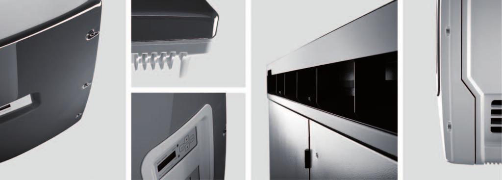
96
PV Inverter SUNNY BOY 3300/3800
 PV Inverter SUNNY BOY 3300/3800 Installation Guide SB33_38-IEN111851 IME-SB3800 Version 5.1 EN SMA Solar Technology AG Table of Contents Table of Contents 1 Notes on this Guide...............................
Wind Power Inverter WINDY BOY 1200/1700
 Wind Power Inverter WINDY BOY 1200/1700 Installation Manual WB12-17-IA-IEN111840 IME-WB11-17 Version 4.0 EN SMA Solar Technology AG Table of Contents Table of Contents 1 Information on this Document.......................
PV Inverter SUNNY BOY 3300/3800
 PV Inverter SUNNY BOY 3300/3800 Installation Manual SB33-38-11-IA-en-62 IMEN-SB33-38-11 Version 6.2 EN SMA Solar Technology AG Table of Contents Table of Contents 1 Information on this Manual.........................
Accessories for Wind Power Inverter WINDY BOY PROTECTION BOX 400 / 500 / 600
 Accessories for Wind Power Inverter WINDY BOY PROTECTION BOX 400 / 500 / 600 Installation Guide WBP-Box-IEN103320 IMEN-WBP-BOX Version 2.0 EN SMA Solar Technology AG Table of Contents Table of Contents
Wind Power Inverter WINDY BOY 5000A/6000A
 Wind Power Inverter WINDY BOY 5000A/6000A User Manual WB5A-6A-BA-BEN114530 TBEN-WB50-60A Version 3.0 EN SMA Solar Technology AG Table of Contents Table of Contents 1 Information on this Manual.........................
Wind Power Inverter WINDY BOY 1100LV
 Wind Power Inverter WINDY BOY 1100LV Installation Guide WB1100LV-IA-IEN104130 IME-WB1100LV Version 3.0 EN SMA Solar Technology AG Table of Contents Table of Contents 1 Notes on this Guide...............................
PV Inverter SUNNY MINI CENTRAL 9000TL / 10000TL / 11000TL with Reactive Power Control
 PV Inverter SUNNY MINI CENTRAL 9000TL / 10000TL / 11000TL with Reactive Power Control User Manual SMC9-11TLRP-BA-en-30 TBEN-SMCTLRP Version 3.0 EN SMA Solar Technology AG Table of Contents Table of Contents
PV inverter SUNNY BOY 2100TL
 PV inverter SUNNY BOY 2100TL Installation Guide SB2100TL-IEN091730 IME-SB21TL Version 3.0 EN SMA Solar Technology AG Table of Contents Table of Contents 1 Notes on this Manual..............................
PV inverter SUNNY MINI CENTRAL 7000HV
 PV inverter SUNNY MINI CENTRAL 7000HV User Manual SMC70HV11-BA-BEN112930 TBEN-SMC70HV Version 3.0 EN SMA Solar Technology AG Table of Contents Table of Contents 1 Information on this Manual.........................
Wind power inverter WINDY BOY 5000-US/6000-US WINDY BOY 7000-US/8000-US. 1 Notes on this addendum. 1.1 Validity. 1.2 Target group
 Wind power inverter WINDY BOY 5000-US/6000-US WINDY BOY 7000-US/8000-US Addendum operating requirements 1 Notes on this addendum 1.1 Validity This addendum does not replace the attached Sunny Boy installation
Accessories for Stand-alone inverter SUNNY ISLAND GENMAN
 Accessories for Stand-alone inverter SUNNY ISLAND GENMAN Technical Description GenMan-TEN082730 98-2001230 Version 3.0 EN SMA Solar Technology AG Table of Contents Table of Contents 1 Notes on this manual..............................
Sunny Boy Accessories SUNNY BOY COMBINER BOX TLUS SBCBTL6
 Sunny Boy Accessories SUNNY BOY COMBINER BOX TLUS SBCBTL6 Installation Guide SBCBTLUS-IUS094510 IMUS-SBCBTLUS Version 1.0 US SMA America, LLC Legal Restrictions Copyright 2010 SMA America, LLC. All rights
Version: 1.0 Mat.-Nr.: DBUS-WB50-80US
 WINDY BOY 3000-US / 5000-US / 6000-US / 7000-US / 8000-US Addendum operating requirements Version: 1.0 Mat.-Nr.: DBUS-WB50-80US 1 Notes on this addendum 1.1 Validity This addendum does not replace the
PV Inverter SUNNY BOY 2000HF-US / 2500HF-US / 3000HF-US
 PV Inverter SUNNY BOY 2000HF-US / 2500HF-US / 3000HF-US Installation Guide SB20-30HF-US-IA-en-12 IMUS-SB20-30HFUS Version 1.2 CA US SMA America, LLC Copyright 2012 SMA America, LLC. All rights reserved.
Charge controller SUNNY ISLAND CHARGER
 Charge controller SUNNY ISLAND CHARGER Installation Guide SIC50-IA-IEN111010 IMEN-SIC50 Version 1.0 EN SMA Solar Technology AG Table of Contents Table of Contents 1 Notes on this Manual..............................
Accessories for power generation plants in Italy SMA GRID GATE
 Accessories for power generation plants in Italy SMA GRID GATE Installation Manual GridGate-11-IA-en-12 Version 1.2 EN SMA Solar Technology AG Table of Contents Table of Contents 1 Information on this
Multi-Function Interface MULTI-FUNCTION RELAY
 Multi-Function Interface MULTI-FUNCTION RELAY Installation Manual MFR-NR-IA-en-20 98-1000220 Version 2.0 EN SMA Solar Technology AG Table of Contents Table of Contents 1 Information on this Document...........................
Operating instructions. sonnenprotect for operators. KD-337 Part no Version X00.
 Operating instructions for operators sonnenprotect 1300 KD-337 Part no. 22010 Version X00 info@sonnenbatterie.de www.sonnenbatterie.de EN IMPORTANT Read this documentation carefully before operation. Retain
System Monitoring SCHOOLMETERBOX AU
 System Monitoring SCHOOLMETERBOX AU Installation Guide SMETER-IEN084710 98-00013210 Version 1.0 EN SMA Solar Technology AG Table of Contents Table of Contents 1 Notes on this Manual..............................
KeContact P20. User manual
 KeContact P20 User manual Comments to this manual In this manual you will find warnings against possible dangerous situations. The used symbols apply to the following meanings:!! WARNING! Indicates a potentially
User Manual. Solar Charge Controller 3KW
 User Manual Solar Charge Controller 3KW 1 CONTENTS 1 ABOUT THIS MANUAL... 3 1.1 Purpose... 3 1.2 Scope... 3 1.3 SAFETY INSTRUCTIONS... 3 2 INTRODUCTION... 4 2.1 Features... 4 2.2 Product Overview... 5
Operating Manual SUNNY BOY 3600 / 5000 SMART ENERGY BATTERY PACK SMART ENERGY
 Operating Manual SUNNY BOY 3600 / 5000 SMART ENERGY BATTERY PACK SMART ENERGY SB36-50SE-BE-en-11 98-112900.02 Version 1.1 AMERICAN ENGLISH Legal Provisions SMA Solar Technology AG Legal Provisions The
SI AT A22. English. Printed: Doc-Nr: PUB / / 000 / 01
 SI AT A22 English 1 Information about the documentation 1.1 About this documentation Read this documentation before initial operation or use. This is a prerequisite for safe, trouble-free handling and
Manual. BlueSolar Grid Inverter 1500 / / / / / 230
 Manual EN BlueSolar Grid Inverter 1500 / 230 2000 / 230 2800 / 230 4000 / 230 5000 / 230 Before you start This manual contains important information regarding installation and safe operation of this unit.
SI AT A22. English. Printed: Doc-Nr: PUB / / 000 / 03
 SI AT A22 English 1 Information about the documentation 1.1 About this documentation Read this documentation before initial operation or use. This is a prerequisite for safe, trouble-free handling and
Installation and operating instructions. Solar charge controller MPPT 10 A / 20 A Z Z
 Installation and operating instructions Solar charge controller MPPT 10 A / 20 A EN 1 Contents 1. About these instructions... 3 1.1 Applicability... 3 1.2 Users... 3 1.3 Description of symbols... 3 2.
Micro Inverter with Communication Unit SUNNY BOY 240-US SUNNY MULTIGATE-US
 Micro Inverter with Communication Unit SUNNY BOY 240-US SUNNY MULTIGATE-US Installation Manual SMG-SB240US-IA-en-11 Version 1.1 CA US Legal Provisions Legal Provisions Copyright 2013. All rights reserved.
MAKING MODERN LIVING POSSIBLE. UniLynx Indoor Installation Manual. ULX 1800i ULX 3000i ULX 3600i ULX 5400i SOLAR INVERTERS
 MAKING MODERN LIVING POSSIBLE UniLynx Indoor Installation Manual ULX 1800i ULX 3000i ULX 3600i ULX 5400i SOLAR INVERTERS Contents Contents 1. Introduction 2 Introduction 2 Installation Sequence 2 Important
User Manual. Hybrid PV Inverter. Version: 2.1
 User Manual Hybrid PV Inverter Version: 2.1 Table Of Contents 1. Introduction...1 2. Important Safety Warning...2 3. Unpacking & Overview...4 3-1. Packing List... 4 3-2. Product Overview... 4 4. Installation...5
Pressure chlorine changeover unit C 7520
 BW 2 24 04 / 1 Content 1. Scope of delivery 2. Device description 3. Installation 4. Operation 5. Shutdown 6. Maintenance 7. Troubleshooting 1 Scope of delivery The chlorine gas changeover unit C 7520
Operating Manual SUNNY TRIPOWER 15000TL / 20000TL / 25000TL
 Operating Manual SUNNY TRIPOWER 15000TL / 20000TL / 25000TL ENGLISH STP15-25TL-30-BE-en-13 Version 1.3 Legal Provisions SMA Solar Technology AG Legal Provisions The information contained in these documents
User Manual Solar Charge Controller 3KW
 User Manual Solar Charge Controller 3KW Version: 1.3 CONTENTS 1 ABOUT THIS MANUAL... 1 1.1 Purpose... 1 1.2 Scope... 1 1.3 SAFETY INSTRUCTIONS... 1 2 INTRODUCTION... 2 2.1 Features... 2 2.2 Product Overview...
Central Inverter SUNNY CENTRAL 500HE-20/630HE-20/720HE-20/ 760HE-20/800HE-20
 Central Inverter SUNNY CENTRAL 500HE-20/630HE-20/720HE-20/ 760HE-20/800HE-20 Maintenance Manual SC500-800HE20-WH-en-10 98-4110410 Version 1.0 EN SMA Solar Technology AG Table of Contents Table of Contents
User Manual Rittal PMC UPS 6kVA
 User Manual Rittal PMC UPS 6kVA Germany Rittal GmbH & Co. KG Auf dem Stützelberg D-35745 Herborn Tel.: ++49-27 72-5 05-0 Fax: ++49-27 72-5 05-23 19 Internet: www.rittal.de 26 Contents 1. Introduction...
Enelion Vertica. Installation manual. 22 kw. for the specialists
 Enelion Vertica kw Installation manual for the specialists ver..6 Enelion 05.07 Enelion VERTICA General notes At various points in this manual you will see notes and precautionary warnings regarding possible
Battery Power Inverters
 Battery Power Inverters Renogy 500W 1000W 2000W Pure Sine Wave Inverter Manual 2775 E. Philadelphia St., Ontario, CA 91761 1-800-330-8678 1 Version 1.4 Important Safety Instructions Please save these instructions.
Operating Manual (Edition 04/2004) sinamics. Braking Module / Braking Resistor SINAMICS G130
 sinamics. Braking Module / Braking Resistor SINAMICS G130") Operating Manual (Edition 04/2004) sinamics Braking Module / Braking Resistor SINAMICS G130 04/04 Contents Contents 1 Safety Information 1-1 2 General 2-1 3 Mechanical Installation 3-1 4 Connection 4-1
Operating Manual (Edition 04/2004) sinamics Braking Module / Braking Resistor SINAMICS G130 04/04 Contents Contents 1 Safety Information 1-1 2 General 2-1 3 Mechanical Installation 3-1 4 Connection 4-1
1. INTRODUCTION SYSTEM DESCRIPTION Front Panel CONNECTION AND OPERATION TROUBLESHOOTING...8
 Contents : 1. INTRODUCTION...1 2. IMPORTANT SAFETY INSTRUCTIONS...2 3. SYSTEM DESCRIPTION...4 3.1 Front Panel...4 4. CONNECTION AND OPERATION...6 5. TROUBLESHOOTING...8 6. MAINTENANCE...9 6.1 Operation...9
Installation and operating instructions. Solar charge controller 10 A / 15 A / 0 A / 30 A PHOTOVOLTAIK - PHOTOVOLTAICS - PHOTOVOLTAIQUE - FOTOVOLTAICA
 PHOTOVOLTAIK - PHOTOVOLTAICS - PHOTOVOLTAIQUE - FOTOVOLTAICA Installation and operating instructions Solar charge controller 10 A / 15 A / 0 A / 30 A EN 74.86 08.4 1. About this manual These operating
Operating instructions
 Operating instructions Digital tank contents indicator DTA 10 DTA 10 DTA 10 0 4.0 m fuel oil 0 3.5 m water Read instructions before using device! Observe all safety information! Keep instructions for future
User Manual. 3kW Hybrid PV Inverter HX-3000
 User Manual 3kW Hybrid PV Inverter HX-3000 Table Of Contents 1. Introduction...1 2. Important Safety Warning...2 3. Unpacking & Overview...4 3-1. Packing List... 4 3-2. Product Overview... 4 4. Installation...5
System Monitoring SUNNY SENSORBOX
 System Monitoring SUNNY SENSORBOX Installation Manual Sensorbox-eng-IA-IUS-112515 98-0003915 Version 1.5 CA US SMA America, LLC Legal Restrictions Copyright 2011 SMA America, LLC. All rights reserved.
INSTALLATION AND OPERATING INSTRUCTIONS SOLAR HEATING PROGRAMMER TDS SD UK/IE (2010/04)
") INSTALLATION AND OPERATING INSTRUCTIONS SOLAR HEATING PROGRAMMER TDS 300 6720613720-00.1 SD UK/IE CONTENTS Contents Contents 2 1 Safety instructions and explanation of symbols 5 1.1 General safety instructions
INSTALLATION AND OPERATING INSTRUCTIONS SOLAR HEATING PROGRAMMER TDS 300 6720613720-00.1 SD UK/IE CONTENTS Contents Contents 2 1 Safety instructions and explanation of symbols 5 1.1 General safety instructions
Emergency Power Supply for the OMEGA ACTIVE-System. Operating Instructions
 Emergency Power Supply for the OMEGA ACTIVE-System Operating Instructions Preface Preface These Operating Instructions will help you using the Emergency Power Supply as intended, safely, and advantageously.
Level Measuring Sensor for Diesel Fuel Tanks
 Installation and Operating Manual Level Measuring Sensor for Diesel Fuel Tanks Executions with switchable output voltage signal: 0-2.3 V and industrial standard signal 0-10 V: Tank Sensor Diesel 010-250
Inverter / Charger Accessory for Steca Solarix PLI Phase / Parallel Kit. Installation and operating instructions Z01 17.
 Inverter / Charger Accessory for Steca Solarix PLI 5000-48 3-Phase / Parallel Kit Installation and operating instructions GB Z01 17.31 Table of Contents About this Manual... 2 Purpose... 2 Scope... 2 Keywords
SOLAR CHARGE CONTROLLER
 SOLAR CHARGE CONTROLLER SCE 1010 / SCE 1515 / SCE 2020 / SCE 3030 Instruction Manual Please read user manual carefully before use. 1.About this manual These operating instructions are part of the product.
c-go 24V/6A 24V/8A 24V/12A
 c-go 24V/6A 24V/8A 24V/12A Battery charger GB Instruction manual 1 Index 1. Product description... 2 2. Safety advices... 3 3. Quick start guide... 4 4. Operation... 4 5. Problem solving... 6 6. Specifications...
Installation manual portable distributors
 EN Installation manual portable distributors EN 60003206 Issue 11.2016 15/11/2016 Table of contents 1 About this manual 3 1.1 Structure of the warnings 3 1.2 Symbols used 4 1.3 Signal words used 4 2 Intended
HANGKAI GROUP HOYMILES MICRO-INVERTER MI-250
 HANGKAI GROUP HOYMILES MICRO-INVERTER MI-250 TECHNICAL MANUAL CONTENTS INTRODUCTION... 3 SAFETY... 4 SYMBOL ILLUSTRATION... 4 INSTALLATION WARNINGS... 6 PREPARE FOR INSTALLING... 7 TRANSPORT AND INSPECT...
Installation manual wall-mounted distributor
 EN Installation manual wall-mounted distributor EN 60003233 Issue 11.2016 2016-14-11 Table of contents 1 About this manual 3 1.1 Structure of the warnings 3 1.2 Symbols used 4 1.3 Signal words used 4 2
Wilo-Control SC-Fire Jockey
 Pioneering for You Wilo-Control SC-Fire Jockey de en fr Einbau- und Betriebsanleitung Installation and operating instructions Notice de montage et de mise en service nl Inbouw- en bedieningsvoorschriften
YSmart Technology Co., Ltd. User Manual. GTI Grid Series. GTI Series Inverters for Grid-connected PV system
 YSmart Technology Co., Ltd. User Manual Contact Us Address: No. 30 XinFeng Road,Potoubei Village,Ailian Town,Longgang Dist, Shenzhen 51872,P.R. China Tel: (86)755-85232255 Fax: (86)755-85232255 Email :
CPS Energy Balancer. Version: 1.0
 CPS Energy Balancer Version: 1.0 CHINT POWER SYSTEMS AMERICA CO., LTD. Address: 700 International Parkway, Suite 102 Richardson, Texas Zip Code: 75081 Web: www.chintpower.com/na Email: americasales@chintpower.com
PURE SINE WAVE DC TO AC POWER INVERTER
 PURE SINE WAVE DC TO AC POWER INVERTER 60S-12A / 60S-24A 60S-12E / 60S-24E 100S-12A / 100S-24A 100S-12E / 100S-24E 150S-12A / 150S-24A 150S-12E / 150S-24E Instruction manual SINE WAVE INVERTER Please read
Technical Documentation
 Technical Documentation Product manual Holding brake controller Document: 0198441113316 Edition: V1.00, 03.2006 Important information The drive systems described here are products for general use that
Galaxy VM. Battery Breaker Box Installation 09/
 Galaxy VM Battery Breaker Box Installation 09/2016 www.schneider-electric.com Legal Information The Schneider Electric brand and any registered trademarks of Schneider Electric Industries SAS referred
Overview of the Rotary Switch Settings for SMA PV inverter, status 03/2018 SUNNY BOY / SUNNY TRIPOWER
 SMA PV inverter, status 03/2018 SUNNY BOY / SUNNY TRIPOWER 1 Validity This overview contains the valid rotary switch tings for the following SMA inverters: 2000 / 2500 / 3000 2500 / 3000 3000 / 3600 /
Off-Grid Inverter SUNNY ISLAND 4548-US/6048-US
 Off-Grid Inverter SUNNY ISLAND 4548-US/6048-US Technical description SI4548_6048-US-TB_en-13 Version 1.3 US SMA America, LLC Legal Provisions Legal Provisions Copyright 2013 SMA America, LLC. All rights
Original Operating Manual
 2010-10-29 Original Operating Manual Control Panel Comfort for Pedelecs Series 4313 Save for future use! Marquardt GmbH Schlossstraße 16 78604 Rietheim-Weilheim E-mail: marquardt@marquardt.de Website:
C3 Operating Instructions
 Version 3.1 Stand 09.2014 Robert Bosch (Australia) Pty. Ltd. 1555 Centre Road Clayton, Victoria 3168 C3 Operating Instructions For further information please contact Bosch at: Australia 1300 30 70 40 www.boschautoparts.com.au
Swing Piston Compressors and Vacuum Pumps
 Swing Piston Compressors and Vacuum Pumps NPK 018 AC Pressure NPK 018 DC Pressure NPK 018 AC Vacuum NPK 018 DC Vacuum Operating and Installation Instructions Read and observe these Operating and Installation
Central Inverter SUNNY CENTRAL 500CP-JP / 500CP XT / 630CP XT / 720CP XT / 760CP XT / 800CP XT / 850CP XT / 900 CP XT
 Central Inverter SUNNY CENTRAL 500CP-JP / 500CP XT / 630CP XT / 720CP XT / 760CP XT / 800CP XT / 850CP XT / 900 CP XT Maintenance Manual SCCP-WH-B4-en-20 98-4046720 Version 2.0 EN SMA Solar Technology
Siemens Drives & PLCs
 Preface Overview 1 SIMATIC Industrial PC, Industrial monitor SIMATIC IPC277D/E 19" INOX PRO, SIMATIC IFP1900 INOX PRO Service Manual Safety instructions 2 Replacing the seal of the compartment cover 3
UGE-4K Off-Grid Controller OWNER S MANUAL
 UGE-4K Off-Grid Controller OWNER S MANUAL CONTENTS INTRODUCTION... 3 PARTS LIST... 4 SPECIFICATIONS... 5 SAFETY INSTRUCTIONS... 6-7 INSTALLATION... 8 MOUNTING GUIDE... 9 WIRING DIAGRAM... 10 CONTROLLER
DC Master 24/ A
 USERS MANUAL DC Master 24/12 50-60A DC-DC converter MASTERVOLT Snijdersbergweg 93, 1105 AN Amsterdam The Netherlands Tel.: +31-20-3422100 Fax.: +31-20-6971006 www.mastervolt.com ENGLISH Copyright 2015
c-go 12V/10A 12V/20A Power supply and battery charger Instruction manual
 c-go 12V/10A 12V/20A Power supply and battery charger GB Instruction manual 1 Index 1. Product description... 2 2. Safety advices... 3 3. Mounting and installation... 4 4. Operation... 5 5. Problem solving...
Fuel cell inverter HYDRO BOY 1124 / 1324
 Fuel cell inverter HYDRO BOY 1124 / 1324 Technical Description HB1124-TEN093421 98-2001921 Version 2.1 EN SMA Solar Technology AG Table of Contents Table of Contents 1 Notes on this manual..............................
Technical Information Temperature Derating for Sunny Boy and Sunny Tripower
 Technical Information Temperature Derating for Sunny Boy and Sunny Tripower Temperature derating occurs when the inverter reduces its power in order to protect components from overheating. This document
HOYMILES MICRO-IVERTER MI-250
 HOYMILES MICRO-IVERTER MI-250 TECHNICAL MANUAL CONTENTS INTRODUCTION... 3 SAFETY... 4 SYMBOL ILLUSTRATION... 4 INSTALLATION WARNINGS... 5 PREPARE FOR INSTALLING... 6 TRANSPORT AND INSPECT... 6 CHECK INSTALLATION
Solar Inverter SUNNY BOY 5000US / 6000US / 7000US
 Solar Inverter SUNNY BOY 5000US / 6000US / 7000US Installation Guide SB50US-70US-IUS091924 TBUS-SB50_60_70US Version 2.4 US Copyright 2009 SMA America, Inc. All rights reserved. No part of this document
Compact System NRGS 11-2 NRGS Original Installation Instructions English
 Compact System NRGS 11-2 NRGS 16-2 EN English Original Installation Instructions 810366-05 1 Contents Important Notes Page Usage for the intended purpose...4 Safety note...4 LV (Low Voltage) Directive
Pulsar EXtreme CLA 1500C
 www.mgeups.com MGE UPS SYSTEMS Pulsar EXtreme CLA 500C Installation and user manual 503998EN/AA - Page Introduction Thank you for selecting an MGE UPS SYSTEMS product to protect your electrical equipment.
Operating Instructions
 Operating Instructions Ex UPS Combination of > 8265/5 GUBox control panel > 8316 battery box Contents 1 Contents 1 Contents 2 2 General Information 2 3 Safety Instructions 2 4 Conformity to standards 3
Matrix APAX. 380V-415V 50Hz TECHNICAL REFERENCE MANUAL
 Matrix APAX 380V-415V 50Hz TECHNICAL REFERENCE MANUAL WARNING High Voltage! Only a qualified electrician can carry out the electrical installation of this filter. Quick Reference ❶ Performance Data Pages
Altivar Regenerative Unit
 Altivar Regenerative Unit User Manual 11/2016 NVE88423-10/2016 www.schneider-electric.com The information provided in this documentation contains general descriptions and/or technical characteristics of
Switching DC Power Supply
 99 Washington Street Melrose, MA 02176 Phone 781-665-1400 Toll Free 1-800-517-8431 Visit us at www.testequipmentdepot.com Model 1693, 1694 Switching DC Power Supply INSTRUCTION MANUAL 1 Safety Summary
Sunny Central Accessories SUNNY CENTRAL STRING-MONITOR US
 Sunny Central Accessories SUNNY CENTRAL STRING-MONITOR US Technical Description SSMUS-TUS094511 98-4001411 Version 1.1 US Copyright 2009 SMA America, Inc. All rights reserved. No part of this document
The Traveler Series: Adventurer
 The Traveler Series: Adventurer RENOGY 30A Flush Mount Charge Controller Manual 2775 E. Philadelphia St., Ontario, CA 91761 1-800-330-8678 Version: 2.2 Important Safety Instructions Please save these instructions.
Operating Manual NA-BOX 12
 Operating Manual NA-BOX 12 NA-BOX-12-3-20-BE-en-11 Version 1.1 ENGLISH Legal Provisions SMA Solar Technology AG Legal Provisions The information contained in this document is the property of SMA Solar
RollSeal 1733 County Road 68 Bremen, Alabama Part No Rev Owner s Manual RS-Divider Curtain
 1. 2. 7 3. 4. RollSeal 1733 County Road 68 Bremen, Alabama 35033 256-287-7000 Part No 4801-5176 Rev 12-11-17 Owner s Manual RS-Divider Curtain Table of Contents 1 Warnings (Avertissements)... 3 2 Limited
NEW SOLAR CHARGE CONTROLLERS
 190 SOLAR CHARGE CONTROLLERS Steca Solarix 2020-x2 Dual battery charge controller The Steca Solarix 2020-x2 is a state-of-the-art dual battery charge controller that is ideal for use in leisure applications.
PowerLogic High Density Metering System 4-Meter Enclosure Installation Guide
 PowerLogic High Density Metering System 4-Meter Enclosure Installation Guide 7002-0289-00 Instruction Bulletin HAZARD CATEGORIES AND SPECIAL SYMBOLS Read these instructions carefully and look at the equipment
Porte 150 Users Manual Swing Gate Opener 24V DC
 Porte 150 Users Manual Swing Gate Opener 24V DC for residential use only Signal Light Push-button Control Box 14 Contents 1. Important Safety Information 2. Product Description and Application 2.1 Application
Installation Manual SUNNY TRIPOWER 5000TL / 6000TL / 7000TL / 8000TL / 9000TL
 Front cover Installation Manual SUNNY TRIPOWER 5000TL / 6000TL / 7000TL / 8000TL / 9000TL STP5-9TL-IA-en-12 Version 1.2 ENGLISH Legal Provisions SMA Solar Technology AG The information contained in these
HIGH FREQUENCY AUTOMATIC BATTERY CHARGER
 HIGH FREQUENCY AUTOMATIC BATTERY CHARGER MODEL NO: HFBC12 PART NO: 6267000 OPERATION & MAINTENANCE INSTRUCTIONS LS0814 INTRODUCTION Thank you for purchasing this CLARKE High Frequency Automatic Battery
Pulsar Evolution 1500 / 1500 Rack 1100 / 1100 Rack 800 / 800 Rack 500 Rack
 www.mgeups.com MGE UPS SYSTEMS Pulsar Evolution 1500 / 1500 Rack 1100 / 1100 Rack 800 / 800 Rack 500 Rack Installation and user manual S T O P Y O U N O W L L W I N G I T H N O 34007117EN/AB - Page 1 Page
Safety. Operating instructions Solenoid valve VGP DANGER. Contents WARNING CAUTION. Changes to edition Elster GmbH Edition 10.
 27 Elster GmbH Edition.7 Translation from the German 344297 D F NL I E DK S N P GR TR CZ PL RUS H www.docuthek.com Operating instructions Solenoid valve Contents Solenoid valve... Contents... Safety....
BMW i. Freude am Fahren. Wallbox PURE. Installation instruction
 BMW i Freude am Fahren Wallbox PURE Installation instruction Imprint Bestellnummer 61 90 2 347 662 Wallbox Pure Type T2 (32 A, 7.4 kw) Publisher Bayerische Motorenwerke Aktiengesellschaft Munich, Germany
Multi-Mover Charger for model L25
 Multi-Mover Charger for model L25 Important safety instruction. Keep these instructions. This manual contains important instructions for the safety of the user and the operation of the device. 1. SYMBOLS
FREQUENCY INVERTER INSTALLATION & USER GUIDE
 En FREQUENCY INVERTER INSTALLATION & USER GUIDE Thank you for purchasing our frequency inverter. Please read the manual carefully before installing or using it and keep it for future reference after installation.
10A / 15A / 20A Solar Charge Controller. PU1024 / PU1524 / PU2024 series INSTRUCTION MANUAL
 10A / 15A / 20A Solar Charge Controller PU1024 / PU1524 / PU2024 series INSTRUCTION MANUAL Dear Customer, Thank you very much for choosing our product. This manual contains important information about
SYMBOL LEGEND DANGER WARNING NOTE THIS INDICATES DANGER TO THE LIFE AND HEALTH OF THE USER IS APPROPRIATE PRECAUTIONS ARE NOT TAKEN
 SYMBOL LEGEND DANGER THIS INDICATES DANGER TO THE LIFE AND HEALTH OF THE USER IS APPROPRIATE PRECAUTIONS ARE NOT TAKEN WARNING THIS WARNS THAT MATERIALS MAY BE DAMAGED IF APPROPRIATE PRECAUTIONS ARE NOT
Battery Charger JCB-FCH12Li
 Safety and operating manual Battery Charger JCB-FCH12Li ORIGINAL INSTRUCTIONS SAFETY INSTRUCTIONS WARNING: Read all safety warnings and all instructions.failure to follow the warnings and instructions
USER MANUAL FOR 2000 WATTS POWER INVERTER USER S MANUAL--Read before operating this equipment
 USER MANUAL FOR 2000 WATTS POWER INVERTER Your 2000 watts power inverter converts 12-volt vehicle battery power into 230 volts of AC power. You can use the inverter in your vehicle to operate many types
User s Manual. Automatic Switch-Mode Battery Charger
 User s Manual Automatic Switch-Mode Battery Charger IMPORTANT Read, understand, and follow these safety rules and operating instructions before using this battery charger. Only authorized and trained service
INSTRUCTION & INSTALLATION
 INSTRUCTION & INSTALLATION MANUAL MODELS: CCL-eHOME T1C16 CCL-eHOME T1C32 CCL-eHOME T2C16 CCL-eHOME T2C32 WALLBOX ehome SERIES WALLBOX ehome Instruction and Installation manual This document is copyrighted,
T Series (N6052T) Solar Battery Hybrid System. Installation Manual Version 1.1
 Solar Battery Hybrid System. Installation Manual Version 1.1") T Series (N6052T) Solar Battery Hybrid System Installation Manual Version 1.1 Content 1. Safety... 1 1.1 How to Use This Manual... 1 1.2 Safety Rules... 1 1.3 Warning Notices Affixed to the Device... 2
T Series (N6052T) Solar Battery Hybrid System Installation Manual Version 1.1 Content 1. Safety... 1 1.1 How to Use This Manual... 1 1.2 Safety Rules... 1 1.3 Warning Notices Affixed to the Device... 2
SPARKSCAN1 HIGH VOLTAGE CLAMP OPERATING MANUAL
 SPARKSCAN1 HIGH VOLTAGE CLAMP OPERATING MANUAL MOTORTECH Tools & Test Equipment for Ignition Systems P/N 01.10.019 Rev. 01/2013 Copyright Copyright 2012 MOTORTECH GmbH. All rights reserved. Distribution
My Reserve 500 Install Guide
 My Reserve 500 Install Guide System Overview Diagram Warnings Disclaimer of Liability and Warranty: This guide does not replace the Owner s Guide and Installation Instructions supplied with the components.