Train Simulator 2017 Class 419 MLV. Class 419 MLV. Copyright Dovetail Games 2017, all rights reserved
|
|
|
- Clarissa Booker
- 5 years ago
- Views:
Transcription

1 Class 419 MLV
2 1 BACKGROUND Class 419 MLV Class 419 Design & Specification ROLLING STOCK - LOCOMOTIVES Class 419 MLV in Network SouthEast livery Class 419 MLV in Jaffa Cake livery ROLLING STOCK COACHES & WAGONS Mk1 General Utility Van (GUV) in BR Blue livery TTA Wagon (water only) DRIVING THE CLASS Cab Controls & Keyboard Controls Master Switch Reverser Power Controller Handle Deadman s Handle...9 Camshaft Controller...9 Overloads...11 Safety systems...11 Wheel slip Braking Systems EP Brakes...11 Auto Air Brake...11 Vacuum Brakes...12 Hand Brake Brake Valve Brake Modes Battery Control Line Voltage Parcel System Guard System Efficiency reporting system Automatic Warning System (AWS) Indicator Lights SCENARIOS [MLV] Part 1: Brighton to London Bridge Parcels [MLV] Part 2: Stopper to London Bridge [MLV] Part 3: Parcels to Brighton ACKNOWLEDGEMENTS...17 Page 2
3 Whilst we do our utmost to reproduce sounds that are accurate and true-to-life, sometimes these sounds may not completely tally with the user s expectation. Due to the nature of the simulation, it is often not possible to reproduce a completely accurate soundscape for a variety of reasons such as limitations with our current technology and occasional inability to gain meaningful access to the locomotives being created. You should therefore regard the audio reproduction for our locomotives as authentic interpretations rather than perfect recreations. Page 3
4 1 Background 1.1 Class 419 MLV The British Rail Class 419 Motor Luggage Vans (or MLV) were battery electric multiple unit cars built from by BR at Eastleigh Works. Ten of these units were built for the boat trains from London Victoria to Dover and Folkestone. Units were originally numbered in the range , but were classified Class 419 under the TOPS system and were then renumbered , the numbers actually carried on the units in service reduced to , omitting the first two digits. The units were also fitted with batteries to allow them to operate over the short-distance of nonelectrified line at the quayside. The batteries allowed the units to be used at low-speed for minutes, and could be recharged when the unit was taking power from 750 V DC third-rail. They were withdrawn from traffic in 1991/92, with the closure of Dover Western Docks railway station and the end of the boat train services. 1.2 Class 419 Design & Specification Builder Locomotive Weight Vehicle Length Vehicle Width Top Speed Brake Types Power Output British Railways Eastleigh Works 45 long tons 65ft 6in (21.65m) 9ft (2.74m) 90 MPH (145km/h) Air (Electro-Pneumatic/Auto) & Vacuum 2 x 250 hp (190 kw) traction motors Page 4


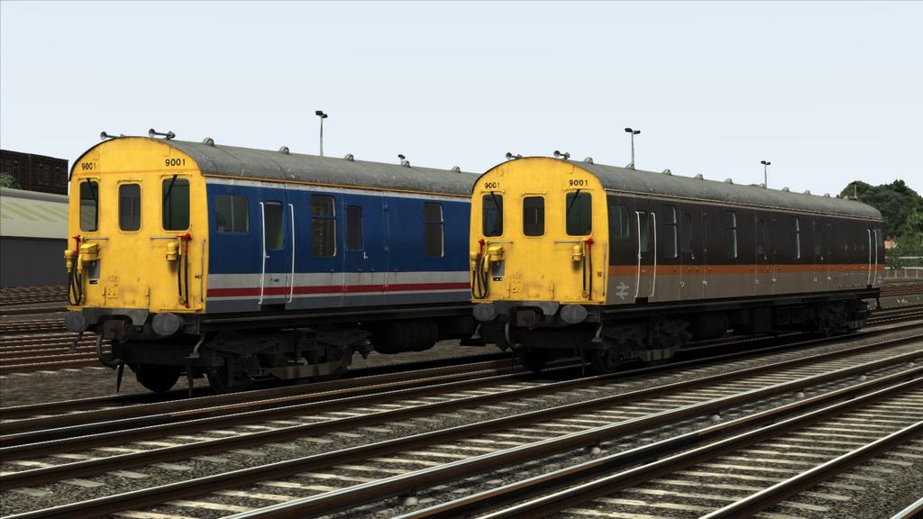
5 2 Rolling Stock - Locomotives 2.1 Class 419 MLV in Network SouthEast livery. 2.2 Class 419 MLV in Jaffa Cake livery. Page 5

 in BR Blue livery 3.")
6 3 Rolling Stock Coaches & Wagons 3.1 Mk1 General Utility Van (GUV) in BR Blue livery 3.2 TTA Wagon (water only) Page 6


7 4 Driving the Class Cab Controls & Keyboard Controls Page 7
, High Tone ( B ) Reverser ( W / S ) 10 11 12 13 14 15 Master Key ( mouse control only ) Master Switch ( X ) Battery Power On/Off ( P ) Series Switch ( Y ) Power Handle ( A / D )")
8 1 2 3 AWS acknowledge ( Q ) Wiper ( V ) Exhauster Speed up ( O ) Train Brake ( ; / ' ) Cab Light ( L ) Instrument Lights ( I ) 24 7 Headlight ( H / Shift+H ) Horn Lever Low Tone (Space), High Tone ( B ) Reverser ( W / S ) Master Key ( mouse control only ) Master Switch ( X ) Battery Power On/Off ( P ) Series Switch ( Y ) Power Handle ( A / D ) Guards Buzzer ( C ) Sun Visor ( U ) Destination Blind 1 ( Ctrl+6 ) Destination Blind 2 ( Ctrl+5 ) Handbrake ( / ) Overload Reset ( R ) Indicator Lights ( EP Brake, Line, Motor Generator) Brake Lap ( ] ) (keyboard control only) Brake Release ( [ ) (keyboard control only) Brake Service (Enter) (keyboard control only) Brake Emergency (Backspace) (keyboard control only) Brake Lap ( ] ) (keyboard control only) Deadman s Handle (Ctrl+D / Ctrl+Shift+D ) (Advanced Mode only, keyboard control only) Advanced/Simple Mode ( Ctrl+B ) Notch Up Power Controller ( Ctrl+A ) Brake Mode Up ( Ctrl+8 ) Brake Mode Down ( Ctrl+7 ) Efficiency Reporting System ( Ctrl+4 ) Only pick up mail bags at next station ( Ctrl+9 ) Reduce number of mail bags picked up ( Ctrl+0 ) Unload all mail bags at next station ( Delete ) Pick up all mail bags at next station ( Home ) Page 8
9 4.2 Master Switch This switch controls the supply of air to the brake valve and activates the desk allowing the power controller and reverser to be used. It must first be unlocked with the master key then pushed forward ( X key or Sander key on the HUD). Doing so will sound an AWS self-test which you will need to acknowledge. Once the master switch is open, you will be able to move the reverser and release the automatic air brake. 4.3 Reverser The reverser selects the desired direction of travel. On the Class 419 it is interlocked with the master switch and the power controller handle. If power controller is not shut, the reverser handle will be locked in either the forward or back position. In addition, the master switch will also lock the reverser in neutral if the switch is closed, while the reverser will lock the master switch if it not in the neutral position. 4.4 Power Controller Handle The Power controller handle on the MLV is quite a complex device. The unit is fitted with an air-oil camshaft controller as fitted to most southern region EMUs built from 1956 onwards. This will be discussed in a later part of this section Deadman s Handle The Class 419 is fitted with a Deadman s handle. Originally the Deadman s system was only active if the reverser was moved to the forward or reverse position. However, this meant the driver could select neutral and coast with Deadman s system disabled! In the mid 1980s BR rectified this by fitting a speed sensor which detected if the unit was above 6mph and so kept the Deadman s system active above this speed. The SSF label on the destination blind case indicates the unit is speed sensor fitted. Upon releasing the Deadman s handle (which was spring loaded) an emergency application of the automatic air brake would ensue. In Train Simulator this system is replicated. By default the Deadman s handle is controlled by the reverser position. As such moving the reverser forward or back will depress the Deadman s handle. However, consequently, if you move the reverser from the direction of travel while moving faster than 6mph, the Deadman s handle will release and as a result an emergency application of the air brake will ensue. If desired, switching to advanced mode with Ctrl+B the Deadman s system is not automatic, as such it must be depressed with Ctrl+D and released with Ctrl+Shift+D Camshaft Controller The unit is fitted with a camshaft controller. By moving the power controller towards the fully open position ( A key to notch up and D key to notch down), this selects the desired target for the camshaft controller. However, reducing the power handle will not reduce the target for camshaft controller and it will continue to notch up to the furthest position. For example, if the handle is moved to the weak field position then back to series, the system will continue to notch up to weak field. The controller has 5 main positions. Off, Shunt, Series, Parallel and Weak field. In the shunt position all the resistances are in the system and so the unit will run at a low speed between 5-10mph depending upon the load and voltage. In Series voltage to the motors is split so the Page 9
10 motors run at half power. In parallel the full voltage is applied to both motors and so the motors run at full power. In weak field, the field coil is weakened increasing the current allowing the unit to reach a higher speed. There are additional resistance notches between Shunt and Series, and Series and weak field. There are 7 series resistances notches with gradually reducing resistances and 4 parallel resistance notches in a similar arrangement. Notching up is done automatically by a system known as a current limiting relay, when the current drops below a specified value (720/900 amps in series, 720 amps in parallel and 1180 amps to enter weak field) the system will notch up one notch. Notching up takes just over 1 second to occur. As such while at speed (greater than 43mph) it will take about 18 seconds to reach weak field from the off position. The transition from series to parallel takes place around 18mph, the transition from parallel to weak field takes place around 43mph. It should be noted the current limiting relay can be halted by returning the power handle to the shunt position, this will arrest the notching up process until the handle is moved back to either series or weak field. Returning the handle straight to off will reduce drop the camshaft back to the first notch. While the system is not replicated on the MLV, you should not run in resistance notches (including shunt) for more than about 4 minutes to prevent overheating and their resultant failure. Ordinarily you would have to shut off and wait about minutes afterwards for the resistances to cool down before reselecting power. If you suspect that you will be unable to reach full parallel in a reasonable time you should use the series switch which will prevent the camshaft from notching up above full series (unless the camshaft is already above full series whereby it will halt its progression, if this happens shut off and reapply power). This will likely be needed in poor adhesion conditions where you will struggle to gain speed quickly enough. The unit has two acceleration rates in series. Moving the handle to either series or parallel will use the lower acceleration rate (720 amps notch up current), while moving the handle straight to weak field will use the higher acceleration rate (900 amp notching up current). The low acceleration rate can come in useful in low adhesion conditions or if you don t need to accelerate quickly. If the adhesion is so bad that even the low acceleration rate is causing wheel to slip you may need to use the shunt position to hold a notch, or use manual notching. On the MLV this is done by rapidly moving the handle from Shunt to Series and back. This notches the system up one notch. As this is difficult to do quickly and accurately enough with keyboard or mouse, a key combination has been set up to manually notch up. This can be done by holding the Ctrl+A key combination. Be careful doing this as you can notch up quicker than intended and thereby cause an overload (trip is at 1500 amps). Under battery power, the current limiting relay will notch up rapidly due to the lower voltage and resultant lower current. This causes an unusual drop in power when transitioning into parallel due to the way the resistors are set up causing you to transition into parallel too early. As such you will likely experience a jolt as the power drops and then a surge as the system continues to rapidly notch up towards full parallel. This behaviour is however to be expected. You may wish to use the series only switch to avoid it. Page 10
11 4.4.3 Overloads While this is quite tricky to do with the MLV, it is possible if for example the unit notches up too early due to wheel slip and the unit suddenly regains traction, or if running on battery power and then switching back to 3 rd rail power underway. If this occurs, return the power handle to off and depress the overload reset but ( R key) Safety systems There are additional safety systems regarding the camshaft controller. Firstly, a no volts relay is fitted which will automatically run down the camshaft if no voltage is being delivered to the motor. The Overload reset is an additional system which will run down the camshaft if activated. Finally, a traction interlock is fitted if the train pipe is pressure drops below 45psi then power will be cut, and will no reengage until pressure has risen above 56psi Wheel slip The MLV is fitted with an advanced adhesion model. There is no wheel slip detection or control systems and such you must be able to recognise wheel slip and act accordingly. The most common way is observing the speedo, if it is seen to rise suddenly and rapidly or indicate above the speed you are travelling you can be sure it is slipping. If wheel slip is detected shut off power and return the handle to the shunt position until the wheels regain traction. You may be unable to avoid wheel slip totally, and may have to live with a small amount of slip. The use of the shunt position and manual notching may be required and this is described in the camshaft control section. 4.5 Braking Systems By far one of the most complex parts of the MLV is its braking system. The unit itself is fitted with 4 types of brakes. These are Electro-Pneumatic Brakes (EP), Westinghouse automatic air brake (auto air), Vacuum and the units hand brake EP Brakes The first and primary brake is the EP Brake. This is a quick acting brake which actuates instantly along the entire length of the train. It operates by allowing air to flow from the main reservoir pipe into the brake cylinders. It is graduable in both application and release and allows an infinite variation of brake cylinder pressure between about 6psi and 52psi. The brake is however not fail safe and can fail. If the EP brake fails the EP indicator light will go out, and there will be no contactor sounds from the brake handle or response either Auto Air Brake Because EP brake is not failsafe, the unit is fitting with an automatic air brake as a backup braking system. However, on the MLV you will find it also will need to be used if operating with air braked stock or vacuum braked stock. The system is slower to respond than the EP Brake and does not actuate instantly along the entire train length, as such you will should familiarise yourself with the brakes slow response. The unit is fitted with triple valves which means the brake is not graduable in release, an increase in brake pipe pressure will cause the brake to release completely, in addition the auxiliary reservoir will need to be recharged once released which can take some time so be very careful on approach to terminus station, be prepared to use the emergency position if need be. Page 11
12 4.5.3 Vacuum Brakes The MLV is unusually for a EMU also fitted with vacuum brakes, all MLVs were fitted with through pipes and proportional valves, however there is some debate as to which were fitted with vacuum exhausters (9001/2 were definitely fitted). However, for gameplay reasons all MLVs in the pack have working vacuum exhausters. The switch to activate the exhauster is not modelled and so the exhauster will only function when a vacuum brake mode is selected. The vacuum brake is also applied by a proportional valve outside the cab, which applies the vacuum brake in proportion to the automatic air brake. The EP brake will have no influence over the vacuum brake. The exhauster can be sped up with the Exhauster speed up button or by pressing the O key Hand Brake The unit is also fitted with a hand brake for parking purposes. This is applied with the / Key. 4.6 Brake Valve The unit is fitted with the typical EP/Auto air brake valve. There are five brake positions on the controller. The details are as follows: Position I: Release and Running Position (EP and Automatic Air Brake). Both EP and automatic air brakes are released. Brake pipe and equalising reservoir are maintained at working pressure (70psi). Position II: Full Service (EP) The EP brake is applied to give maximum brake-cylinder pressure. Between positions I and II the self-lapping mechanism controls the air pressure in the brake cylinder in proportion to the angular movement of the brake controller handle. Position III: Lap (Automatic Air) All ports in the brake controller are closed, and with the automatic brake application the be brake valve may be returned to this position when the desired brake pressure has been obtained. Additional this position will hold any application of the EP brake at the pressure it was last at. Position IV: Service Application (Automatic Air) Operates the automatic air brake only. Position V: Emergency Brake Application (EP and Automatic Air) Both EP and automatic air brake are applied together to the full extent. The EP brake will also be applied more rapidly than in the normal full service position. Be very careful when using the brake controller, accidentally overshooting the EP full service position can hold an application at a lower than desired pressure instead of full service. This however can be very useful when using the automatic air brake only (such as when using vacuum hauled stock) as if you quickly enough the handle can be brought to the lap position without the EP brake having time to apply. On the MLV the brake handle can be applied the normal way with the ; to move the handle towards release, and the key to move towards emergency. However, there are some additional controls added to make your life easier. The [ key will quickly move the brake handle to the release position (much quicker than the normal key), the ] key will move the handle quickly to the Lap position and the Backspace key will quickly move the handle to emergency. The Enter key will move the handle to the automatic air service position Page 12
13 quickly. However if both the Enter and ] key are depressed at the same time the handle is moved to an intermediate application position between the two allowing a more steady rate of application. This can allow some fine applications of the automatic air brake by holding the ] key and tapping enter to make fine applications of the auto air brake. 4.7 Brake Modes To allow realistic brake performance and compatibility with various multiple units the MLV has a variety of generic brake modes which automatically set brake characteristics and also setup the efficiency reporting system. The brake modes can be decreased with Ctrl 7 and increased with Ctrl 8. The brake modes are as follows: Brake Mode 0: MLV + SR EMU fitted with EP/Auto brakes and cast-iron tread brakes: Use this brake mode if operating with a generic EMU fitted with cast iron tread brake behaviour, currently only the MLV is so fitted with this brake behaviour. Brake Mode 1: MLV + rolling stock fitted with single pipe automatic air brake and distributor valves: Use this brake mode if operating rolling stock which use the single pipe automatic air brake only, and are fitted with distributors, for example the TTA wagon. Brake Mode 2: 2 X MLV + Coaching stock fitted with dual pipe air brakes.: Use this brake mode if operating with 2 MLV s heading coaching stock operating with dual pipe automatic air brakes (such as a rail tour). Brake Mode 3: 2 X MLV + Vacuum fitted coaching stock: Use this brake mode if operating with 2 MLV s heading coaching stock operating with Vacuum brake (such as the Vulcan Van Train Rail tour). Brake Mode 4: MLV + Vacuum fitted coaching stock: Use this brake mode if operating with a single MLV s heading coaching stock operating with Vacuum brake (such as the GUVs included with the pack). Brake Mode 5: MLV + 4-EPB: Use this brake mode if operating with the DTG 4-EPB as currently sold. Brake Mode 6: MLV + 2-EPB: Use this brake mode if operating with the DTG 2-EPB as currently sold in the BR blue pack. Brake Mode 7: MLV + 4-CIG or 4-BIG or 4-VEP.: Use this brake mode if operating with the DTG 4-CIG or 4-BIG or 4-VEP as currently sold in their respective packs. Brake Mode 8: MLV + 8-CIG or 8-BIG or 8-VEP.: Use this brake mode if operating with the DTG 8-CIG or 8-BIG or 8-VEP or some combination as currently sold in their respective packs. Brake Mode 9: MLV + 12-CIG or 12-BIG or 12-VEP.: Use this brake mode if operating with the DTG 12-CIG or 12-BIG or 12-VEP or some combination as currently sold in their respective packs. Page 13
14 Brake Mode 10: MLV + 2-HAL.: Use this brake mode if operating with a 2-HAL or other older 4 coach Southern EMU fitted with single pipe automatic air brake. Brake Mode 11: MLV + 4-SUB: Use this brake mode if operating with a 4-SUB or other older 4 coach Southern EMU fitted with single pipe automatic air brake. Brake Mode 12: Custom Brake mode: Use this if you desire to make your own setup using the supplied controllers and scenario scripting. 4.8 Battery Control To allow the MLV to operate over unelectrified lines, the unit is fitted with a series of Lead acid batteries. There are Amp-hour cells, each with a nominal voltage of 2V giving a total of 200V. However actual voltage output of a lead acid battery varies between about 2.15V when fully charged down to 1.8V when practically discharged so voltage will vary between about 215V and 180V depending on the state of charge. When voltage drops below 1.8V the batteries will however be permanently damaged. The state of charge is indicated by the charge meter in the cab. Entering the red is not healthy for the battery so try to avoid it, and above all costs avoid going down to the far left of the red section as this will completely discharge the batteries damaging them and very likely leading you to get stuck without any charge. After repeated use the maximum charge the batteries can hold will decrease, by default this is set to 90% of their original maximum. However, this can be decreased further by use of scenario scripting. Depending upon the use of the batteries and their charge state they can last upwards of 30 minutes of start stop running, however there is no hard and set on how long the batteries will last and it will very much depend upon the initial charge state, degradation of the cells and usage. The batteries are charged from a motor generator feeding the cells at about 200V. Charging from completely discharged to about 70-80% charged can take 4-5 hours, however to reach 98% full charged the batteries will need to charge for upwards of 20 hours. To activate the batteries the Battery on button needs to be depressed (alternatively the P key). This will deactivate the motor generator which will stop the batteries charging. To switch back to 3 rd rail power the P key again can be pressed or the battery off button depressed and charging will resume. 4.9 Line Voltage On the southern region, the line voltage is nominally stated to be 750V, however this isn t entirely true and it can vary between 580V and 830V. For timing and motor design purpose s the voltage is taken to be 90% of the maximum at 675V. This is the default voltage for the MLV, however this can be adjusted using scenario scripting by adjusting the Line Voltage controller. In addition, this can be set to 0 for non-electrified track. The unit will react accordingly, increasing, or decreasing performance depending on supplied voltage. Page 14
15 4.10 Parcel System The MLV is fitted with a unique parcels system. At each station, a select amount of mail bags will be unload or loaded. This is randomized after each station. In addition, the randomization can be varied by using a few additional controls. By pressing the Ctrl+9 key, succeeding stations will only pickup mail bags not drop off. Ctrl+0 will reduce the maximum number of parcels at each station to be loaded and unloaded from around 35 to around 8. The Delete key will override the above and cause the next station stop to unload all mail bags from the MLV. The Home key will do the opposite and cause the next station to apply a full load of mail bags Guard System The MLV is fitted with a guard system, this system is active when the doors of the MLV are open. It provides some measure of protection against accidentally moving with the doors open but does not guarantee a scenario will not fail if you do so. Upon detecting movement, the guard will make an emergency application of the automatic air brake for 15 seconds. However, the air brake may not be quickly enough to stop the scenario failing so do try to avoid it. In addition, since parcel stops can take longer than the typical station stops the doors may remain open after those on the train have shut. The guard will remain active until all doors on the MLV are fully shut. Once done he will give two rings on the bell at which point you may proceed (do not mistake the bell on another EMU for your guard s bell!) Efficiency reporting system The MLV is fitted with an efficiency reporting system which will report various statistics on your current session such as energy consumption, approximate CO 2 production (based on power stations producing CO 2 and respective losses), unit efficiency (useful work over the total energy consumed), average speed and distance travelled. This can be called up at any time with the Ctrl+4 key Automatic Warning System (AWS) The MLV is fitted with a typical AWS system. The system is self-tested once the master switch is opened. On a clear indication a bell will ring and the Sunflower display will change to black if it isn t already. Upon a caution or danger aspect a horn will sound which will need to be cancelled within 2.7 seconds or an emergency application will ensure. The alarm is cancelled as usual with the Q key. After the alarm is cancelled the sunflower display will turn to the yellow and black aspect. On the MLV however if you fail to cancel an application in time, the AWS will cause a brake demand which will last 60 seconds after the alarm has been canceled and you will unable to release the brakes or apply power Indicator Lights There are 3 indicator lights in the MLV cab. The first is the EP indicator light which will be lit if the EP brake is functional. The Next down is the Line light which will indicate if there is a traction voltage available (either by battery or line voltage). The one below is the Motor generator light which will be lit if the motor generator is operable and supply voltage to the controls and charging the batteries. Page 15
16 5 Scenarios 5.1 [MLV] Part 1: Brighton to London Bridge Parcels Take a parcels train from Brighton between South Croydon and London Bridge station. Beware of signals as the lines are busy today! Duration: 30 minutes Difficulty: Medium 5.2 [MLV] Part 2: Stopper to London Bridge Take a MLV leading a 4-VEP from Crystal Palace to London Bridge station. Duration: 30 minutes Difficulty: Medium 5.3 [MLV] Part 3: Parcels to Brighton Take charge of a MLV and take two GUVs bound for Brighton from London Bridge to East Croydon stopping at every station. Be careful as the rails are very slippy today! Duration: 50 minutes Difficulty: Hard Page 16

17 6 Acknowledgements Dovetail Games would like to thank the following people for their contribution to the development of the Class 419 MLV Pack. Beta Testing Team Edward Fisk Class 419 setup, audio & scenarios Page 17
London Transport Heritage Collection
 London Transport Heritage Collection 1 ROLLING STOCK... 4 1.1 Class 20... 4 1.1.1 Background...4 1.1.2 Design & Specification...5 1.2 Pannier 5700 Class... 5 1.2.1 Background...6 1.2.2 Design & Specification...6
GE ARROW III NJ TRANSIT
 GE ARROW III NJ TRANSIT 1 BACKGROUND... 4 1.1 Loco... 4 1.2 Design & Specification... 4 2 ROLLING STOCK... 5 2.1 Arrow III A Car... 5 2.2 Arrow III B Car... 5 3 DRIVING THE ARROW III... 6 3.1 Cab Controls
ÖBB Copyright Dovetail Games 2016, all rights reserved Release Version 1.0
 ÖBB 4020 1 BACKGROUND... 4 1.1 Loco... 4 1.2 Design & Specification... 4 2 ROLLING STOCK... 5 2.1 ÖBB 4020... 5 2.2 ÖBB 4020 New Logo... 6 2.3 ÖBB 4020 Red Grey... 7 3 DRIVING THE ÖBB 4020... 8 3.1 Cab
InterCity BR Class 370 'Advanced Passenger Train - Prototype'
 InterCity BR Class 370 'Advanced Passenger Train - Prototype' Page 1 1 BACKGROUND...4 1.1 InterCity BR Class 370 'Advanced Passenger Train - Prototype'...4 1.2 Class 370 APT-P Design & Specification...4
BR Blue Diesel Electric Pack Classes 09/33/73/416/421
 BR Blue Diesel Electric Pack Classes 09/33/73/416/421 1 BACKGROUND... 3 1.1 Class 09... 3 1.2 Class 33... 4 1.3 Class 73... 5 1.4 Class 416 2EPB... 6 1.5 Class 421 4CIG... 7 2 ROLLING STOCK... 8 2.1 OBA
BR Class 105. Copyright Dovetail Games 2015, all rights reserved Release Version 1.0
 BR Class 105 1 BACKGROUND... 3 1.1 Loco... 3 1.2 Design & Specification... 3 2 ROLLING STOCK... 4 2.1 BR Class 105 DMBS... 4 2.2 BR Class 105 DTCL... 4 3 DRIVING THE BR CLASS 105... 5 3.1 Cab Controls...
Class 180 (Adelante) Copyright Dovetail Games 2015, all rights reserved Release Version 1.0
 Copyright Dovetail Games 2015, all rights reserved Release Version 1.0") Class 180 (Adelante) 1 BACKGROUND... 3 1.1 Class 180 (Adelante)... 3 1.2 Design & Specification... 3 2 ROLLING STOCK... 4 2.1 DMSL A (B)... 4 2.2 MFL (F)... 4 2.3 MSL (E)... 5 2.4 MSLRB (C)... 5 2.5 DMSL
Class 180 (Adelante) 1 BACKGROUND... 3 1.1 Class 180 (Adelante)... 3 1.2 Design & Specification... 3 2 ROLLING STOCK... 4 2.1 DMSL A (B)... 4 2.2 MFL (F)... 4 2.3 MSL (E)... 5 2.4 MSLRB (C)... 5 2.5 DMSL
BR266 Diesel Locomtoive
 BR266 Diesel Locomtoive 1 BACKGROUND... 3 1.1 History... 3 1.2 Design & Specification... 3 2 ROLLING STOCK... 4 2.1 BR266... 4 2.2 Megafret container wagons... 4 3 DRIVING THE BR266... 6 3.1 Cab Controls...
BR 266 Diesel Locomotive
 BR 266 Diesel Locomotive 1 BACKGROUND... 3 1.1 History... 3 1.2 Design & Specification... 3 2 ROLLING STOCK... 4 2.1 BR266... 4 2.2 Megafret container wagons... 4 3 DRIVING THE BR266... 6 3.1 Cab Controls...
Class 455/8 Southern. Copyright Dovetail Games 2015, all rights reserved Release Version 1.0
 Class 455/8 Southern 1 BACKGROUND... 3 1.1 The Multiple Unit... 3 1.2 Design & Specification... 3 2 ROLLING STOCK... 4 2.1 Unit List... 4 3 DRIVING THE CLASS 455/8... 6 3.1 Cab Controls... 6 3.2 Locomotive
Class 24 BR Blue. Copyright Dovetail Games 2015, all rights reserved Release Version 1.0
 Class 24 BR Blue 1 BACKGROUND... 3 1.1 Class 24... 3 1.2 Design & Specification... 3 2 ROLLING STOCK... 4 2.1 Class 24... 4 2.2 BR Blue Mk1 FK... 4 2.3 BR Blue Mk1 SK... 5 2.4 BR Blue Mk1 BG... 5 2.5 Hopper
Southern Railway s15 Class
 Southern Railway s15 Class 1 BACKGROUND... 3 1.1 SR S15 Class... 3 1.2 Design & Specification...3 2 ROLLING STOCK... 4 2.1 SR S15 Locomotive SR Olive Green...4 2.2 SR S15 Locomotive SR Black...4 2.3 SR
Class 205 Diesel Electric Multiple Unit
 Class 205 Diesel Electric Multiple Unit Contents How to install... 2 Technical information... 3 Liveries... 4 Cab guide... 10 Desk... 10 Auxiliary cupboard... 11 Engine room... 11 Battery isolation switch...
London Overground Class 313 EMU
 London Overground Class 313 EMU Page 1 Contents Technical information... 3 Cab guide... 4 Keyboard controls... 6 Features... 7 Advanced and HUD versions... 8 Camshaft traction system... 9 Driver only/guard
Train Simulator 2015 EMD FL9. New Haven EMD FL9. Copyright Dovetail Games 2015, all rights reserved Release Version 1.0. Page 1
 New Haven EMD FL9 Page 1 1 BACKGROUND... 3 1.1 Loco... 3 1.2 Design & Specification... 3 2 ROLLING STOCK... 4 2.1 EMD FL9... 4 2.2 Metro-North Shoreliner III Cab car and Passenger car... 4 3 DRIVING THE
Class 91/Mk4 Enhancement Pack
 Class 91/Mk4 Enhancement Pack Contents How to install... 2 Liveries... 3 Keyboard controls... 6 Features... 7 Dynamic brake simulation... 8 Speed set cruise control... 8 Neutral section functionality...
DB BR361/V60. Copyright Dovetail Games 2015, all rights reserved Release Version 1.0
 DB BR361/V60 1 BACKGROUND... 3 1.1 BR361/V60... 3 1.2 Design & Specification... 4 2 ROLLING STOCK... 5 2.1 BR361/V60... 5 2.2 SGGRSS Freight Wagons... 5 3 DRIVING THE BR361/V60... 6 3.1 Cab Controls...
DB BR261 - Voith Gravita 10BB
 DB BR261 - Voith Gravita 10BB 1 BACKGROUND... 3 1.1 Loco...3 1.2 Design & Specification...3 2 ROLLING STOCK... 4 2.1 DB BR261 Voith Gravita...4 2.2 Zacns 95m Tanker...4 2.3 Rnoos 644...5 2.4 Cab Controls...6
Arriva Trains Wales DMU Pack
 Arriva Trains Wales DMU Pack 1 BACKGROUND... 3 1.1 Class 158... 3 1.2 Design & Specification... 3 1.3 Class 143... 3 1.4 Design & Specification... 3 2 ROLLING STOCK... 4 2.1 Class 158 Arriva Trains Wales...
Amtrak Dash 8-32BWH. Copyright Dovetail Games 2016, all rights reserved Release Version 1.0
 Amtrak Dash 8-32BWH 1 BACKGROUND...... 3 1.1 Loco...3 1.2 Design & Specification...3 2 ROLLING STOCK...... 4 2.1 Amtrak Dash 8-32BWH...4 2.2 Amtrak Dash 8-32BWH Phase III...4 2.3 Amtrak Baggage Heritage...5
DB BR114. Copyright Dovetail Games 2016, all rights reserved Release Version 1.0
 DB BR114 1 BACKGROUND... 3 1.1 BR114... 3 1.2 Design & Specification... 3 2 ROLLING STOCK... 4 2.1 BR114... 4 2.2 Doppelstockwagen... 4 3 DRIVING THE BR114... 6 3.1 Cab Controls... 6 3.2 Locomotive Keyboard
DB BR440. Copyright Dovetail Games 2016, all rights reserved Release Version 1.0
 DB BR440 1 BACKGROUND... 3 1.1 BR440... 3 1.2 Design & Specification... 3 2 ROLLING STOCK... 4 2.1 BR440... 4 3 DRIVING THE BR440... 5 3.1 Cab Controls... 5 3.2 Locomotive Keyboard Controls... 7 3.3 General
Class 605 ICE TD. Copyright Dovetail Games 2014, all rights reserved Release Version 1.0
 Class 605 ICE TD 1 Background... 3 Multiple Unit... 3 Design & Specification... 3 2 Rolling Stock... 4 Class 605 ICE TD... 4 3 Driving the ICE TD... 5 Cab Controls... 5 Keyboard Controls... 6 General Keyboard
ALP-46 New Jersey Transit
 ALP-46 New Jersey Transit 1 BACKGROUND... 3 1.1 Loco... 3 1.2 Design & Specification... 3 1.3 Multi-Level Cab car... 4 1.4 Design & Specification... 4 2 ROLLING STOCK... 5 2.1 NJT ALP-46... 5 2.2 Comet
Virgin Trains First Generation Pack Class 43 HST & Class 47/8
 Virgin Trains First Generation Pack Class 43 HST & Class 47/8 1. BACKGROUND... 3 1.1 V irgin T rains...3 1.2 Class 43 'High Speed Train'...3 1.3 Class 47/8...4 2. ROLLING STOCK... 5 2.1 Class 43 HST...5
HHP-8 Electric Locomotive
 HHP-8 Electric Locomotive 1 BACKGROUND......... 3 1.1 Loco...3 1.2 Design & Specification...3 2 ROLLING STOCK...... 4 2.1 HHP-8 Electric Locomotive...4 2.2 Amcoach...5 2.3 Amcafe...5 3 DRIVING THE HHP-8.........
F40PH-2CAT New Jersey Transit
 F40PH-2CAT New Jersey Transit 1 BACKGROUND... 3 1.1 Loco... 3 1.2 Design & Specification... 3 2 ROLLING STOCK... 4 2.1 F40PH-2CAT... 4 2.2 Comet IV... 4 2.3 Comet V Cab Car... 5 3 DRIVING THE F40PH-2CAT...
Class 220 Voyager. Copyright Dovetail Games 2014, all rights reserved Release Version 1.0
 Class 220 Voyager 1 BACKGROUND... 3 1.1 Class 220 Voyager...3 1.2 Design & Specification...4 2 ROLLING STOCK... 5 3 DRIVING THE CLASS 220 VOYAGER... 7 3.1 Cab Controls...7 3.2 Locomotive Keyboard Controls...9
Class 455/9 Electric Multiple Unit
 Class 455/9 Electric Multiple Unit 1 BACKGROUND... 2 1.1 Class 455/9... 2 1.2 Design & Specification... 2 2 THE CLASS 455/9 ELECTRIC MULTIPLE UNIT... 2 2.1 SWT Livery... 2 2.2 NSE Livery... 3 2.3 BR Livery...
DB BR152. Copyright Dovetail Games 2015, all rights reserved Release Version 1.0
 DB BR152 1 BACKGROUND... 3 1.1 Loco... 3 1.2 Design & Specification... 3 2 ROLLING STOCK... 4 2.1 DB BR152... 4 3 DRIVING THE BR152... 5 3.1 Cab Controls and image... 5 3.2 Keyboard Controls... 7 3.3 General
CLASS 56. Railfreight Sectors. Copyright Dovetail Games 2014, all rights reserved Release Version 1.0
 CLASS 56 Railfreight Sectors 1 BACKGROUND... 3 Class 56 Locomotive...3 Design & Specification...3 ROLLING STOCK 4 Class 56 Railfreight Sectors...4 2 DRIVING THE CLASS 56 DIESEL LOCOMOTIVE... 5 Cab Controls...5
DB Class 420 EMU. AddOn Users Manual
 DB Class 420 EMU AddOn Users Manual 1 Table of Contents History... 3 Technical Data... 4 Sound Playback Information... 4 Driving... 5 Combined Throttle and Brake Control... 5 Indicators... 6 Operating
Class 43 (Valenta)/Mk3 Enhancement Pack
/Mk3 Enhancement Pack") Class 43 (Valenta)/Mk3 Enhancement Pack Contents How to install... 2 Liveries... 3 Keyboard controls... 13 Features... 14 Automatic Train Protection (ATP)... 15 Speed limit display... 15 Brake intervention...
Class 43 (Valenta)/Mk3 Enhancement Pack Contents How to install... 2 Liveries... 3 Keyboard controls... 13 Features... 14 Automatic Train Protection (ATP)... 15 Speed limit display... 15 Brake intervention...
Arriva Trains Wales DMU Pack
 Arriva Trains Wales DMU Pack 1 BACKGROUND...... 3 1.1 Class 158...3 1.2 Class 143...3 2 ROLLING STOCK... 4 2.1 Class 158 Arriva Trains Wales...4 2.2 Class 143 Arriva Trains Wales...4 3 DRIVING THE CLASS
DB Class 424 Electrical Multiple Unit
 DB Class 424 Electrical Multiple Unit 1 THE CLASS 424...2 1.1 Class 424 EMU...2 1.2 Technical Specification...2 2 ROLLING STOCK...3 2.1 DB BR424...3 3 CAB CONTROLS...4 3.1 Controls...4 3.2 Keyboard Guide...5
1003 Orientation B&SVRR 1003 Orientation Page 1 10/23/2009
 1003 Orientation B&SVRR 1003 Orientation Page 1 B&SVRR 1003 Orientation Page 2 CONTROLS AT ENGINEMAN'S POSITION 1. Air Gauges 8. Reverse Lever 2. Load Current Indicating Meter 9. Heater Switch 3. Indicating
GEML Class 90. Contents. Page 1
 GEML Class 90 Contents Technical information... 2 Liveries... 3 Class 90... 3 Mk3 DVT... 5 Mk3 coaches (FO, RFB & SO)... 7 Cab guide... 8 Keyboard controls... 10 Features... 11 Advanced and HUD versions...
Railworks Austria Skyhook Games ÖBB 1014 Manual
 Railworks Austria Skyhook Games ÖBB 1014 Manual Page 1 Index Introduction Page 3 1014 cab and key bindings Page 4 Train Operation Start-up procedure Page 8 Driving procedures Page 9 PZB/Indusi How does
Class 313 Electric Multiple Unit
 Class 313 Electric Multiple Unit Contents How to install... 2 Technical information... 3 Liveries... 4 Cab guide... 8 Standard... 8 Southern... 9 Keyboard controls... 10 Features... 11 Camshaft traction
Class 220 Voyager. Copyright Dovetail Games 2015, all rights reserved Release Version 1.0
 Class 220 Voyager 1 BACKGROUND... 3 1.1 Class 220 Voyager...3 1.2 Design & Specification...4 2 ROLLING STOCK... 5 3 DRIVING THE CLASS 220 VOYAGER... 7 3.1 Cab Controls...7 3.2 Locomotive Keyboard Controls...9
Class 43 (VP185)/Mk3 Enhancement Pack
/Mk3 Enhancement Pack") Class 43 (VP185)/Mk3 Enhancement Pack Contents How to install... 2 Liveries... 3 Keyboard controls... 9 Features... 10 Automatic Train Protection (ATP)... 11 Speed limit display... 11 Brake intervention...
Class 43 (VP185)/Mk3 Enhancement Pack Contents How to install... 2 Liveries... 3 Keyboard controls... 9 Features... 10 Automatic Train Protection (ATP)... 11 Speed limit display... 11 Brake intervention...
FP7 California Zephyr
 FP7 California Zephyr 1 BACKGROUND... 3 1.1 EMD FP7 Western Pacific...3 1.2 EMD F7 Rio Grande...5 2 ROLLING STOCK... 6 2.1 California Zephyr cars...6 2.2 Rio Grande Zephyr cars...6 3 DRIVING THE LOCOMOTIVES...
Class 444 Electric Multiple Unit
 Class 444 Electric Multiple Unit 1 BACKGROUND...2 Class 444 Electric Multiple Unit...2 2 ROLLING STOCK...3 2.1 South West Trains Express White Livery...3 3 DRIVING THE CLASS 444 EMU...6 3.1 Cab Diagram...6
North Jersey Coast & Morristown Lines: Hoboken & New York - Bay Head & Dover
 North Jersey Coast & Morristown Lines: Hoboken & New York - Bay Head & Dover Page 1 1 ROUTE INFORMATION... 5 1.1 The Route... 5 1.2 Route Map... 5 1.3 Focus Time Period... 5 2 GETTING STARTED... 6 2.1
Miami Commuter Rail F40PHL-2
 Miami Commuter Rail F40PHL-2 1 BACKGROUND... 3 1.1 Loco...3 1.2 Design & Specification...3 2 ROLLING STOCK... 4 2.1 F40PHL-2...4 2.2 Coaching Stock...4 3 DRIVING THE F40PHL-2... 6 3.1 Cab Controls...6
DB E10 Expert-Line. Compatible with Train Simulator 2015
 DB E10 Expert-Line Compatible with Train Simulator 2015 Content... 1 1 Information... 3 1.1 DB E10... 3 1.2 DB E10 - Functions available in the Simulation... 3 1.3 Technical Data DB E10... 3 2 The Locomotive...
RhB Enhancement Pack 2
 Train Simulator 2017 RhB Enhancement Pack 2 1 THE GE 4/4 II LOCOMOTIVE... 3 1.1 Locomotive History... 3 1.2 Design & Specification... 3 1.3 Cabin Controls - Refer to the illustrations on page 4... 3 1.4
CLASS 377. Copyright RailSimulator.com 2012, all rights reserved Release Version 1.0
 CLASS 377 1 BACKGROUND......... 3 1.1 Class 377...3 1.2 Design & Specification...3 1.3 Class 377 Consist Formations...3 2 ROLLING STOCK...... 4 3 CREATING A CLASS 377 TRAIN SET..... 7 3.1 Scenario Editor
Operator s Manual Reppo Virtual Rail Vehicles Baldwin DR
 2 Rolling Stock PRR CENTIPEDE UNIT A-1 5823-A1-5834-A1 PRR CENTIPEDE UNIT A-2 5823-A2-5834-A2 PRR B60b BAGGAGE CAR 9200-9399 3 PRR D78d DINING CAR 4470-4474-4475-4478-4486-4490-4491-4492-4494-4497 4 OPERATION
Class 66 Diesel Locomotive Pack 03 Add-on
 Class 66 Diesel Locomotive Pack 03 Add-on 1 BACKGROUND... 2 1.1 Class 66... 2 1.2 Technical Specification... 2 2 LOCOMOTIVE AND ROLLING STOCK... 3 2.1 EWS Class 66 Locomotive... 3 2.2 JGA Aggregate Hopper
Class 90 (Freightliner)
") Class 90 (Freightliner) Contents How to install... 2 Technical information... 3 Liveries... 4 Class 90... 4 Cab guide... 5 Keyboard controls... 7 Features... 8 Braking system (rheostatic/air)... 9 Train
Class 90 (Freightliner) Contents How to install... 2 Technical information... 3 Liveries... 4 Class 90... 4 Cab guide... 5 Keyboard controls... 7 Features... 8 Braking system (rheostatic/air)... 9 Train
MRCE ES64U2 ELECTRIC LOCOMOTIVE. Copyright RailSimulator.com 2013, all rights reserved Release Version 1.0
 MRCE ES64U2 ELECTRIC LOCOMOTIVE 1 BACKGROUND......... 3 1.1 ES64 U2...3 1.2 Design & Specification...3 2 ROLLING STOCK...... 4 2.1 MRCE ES64 U2...4 2.2 SGGRSS Wagon...4 3 DRIVING THE ES64 U2...... 5 3.1
North Jersey Coast Line
 North Jersey Coast Line Page 1 1 ROUTE INFORMATION...... 4 1.1 The Route... 4 1.2 Focus Time Period... 4 2 GETTING STARTED...... 5 2.1 Recommended Minimum Hardware Specification... 5 3 ROLLING STOCK.........
DB Class 101 traffic red Pro-Line
 DB Class 101 traffic red Pro-Line Compatible with Train Simulator 2017 DB Class 101 traffic red with ABpmz IC coaches Content... 2 1 Information... 3 1.1 DB class 101 - Functions available in the Simulation...
DR BR86 Locomotive. Copyright Dovetail Games 2015, all rights reserved Release Version 1.0
 DR BR86 Locomotive 1 BACKGROUND... 3 1.1 BR86 Steam Locomotive... 3 1.2 Design & Specification... 3 2 ROLLING STOCK... 4 2.1 DR BR86 Locomotive... 4 2.2 Shimmns Wagon... 4 2.3 Ucs Wagon... 5 3 DRIVING
DB Class 101 traffic red Expert-Line
 DB Class 101 traffic red Expert-Line Compatible with Train Simulator 2016 DB Class 101 traffic red with ABpmz IC coaches Content... 1 1 Information... 3 1.1 DB class 101 - Functions available in the Simulation...
Class 66 Enhancement Pack
 Class 66 Enhancement Pack Contents How to install... 2 Liveries... 3 Keyboard controls... 10 New features... 11 EM2000 screen... 12 Main Menu... 12 Meter Menu (Page 1)... 12 Meter Menu (Page 2)... 12 Power
Class 45/46 Peak Diesel Locomotives 1 BACKGROUND...2
 Class 45/46 Peak Diesel Locomotives 1 BACKGROUND...2 1.1 Class 45/46 Heritage...2 1.2 Sulzer 12LDA28B Diesel engine...3 1.3 Nose End Variations...3 1.4 Design and Specification...4 2 THE CLASS 45/46 DIESEL
TRAIN SIM WORLD : NORTHERN TRANS-PENNINE DRIVER S MANUAL
 TRAIN SIM WORLD : NORTHERN TRANS-PENNINE DRIVER S MANUAL 1 2018 Dovetail Games, a trading name of RailSimulator.com Limited ( DTG ). All rights reserved. "Dovetail Games", Train Sim World and SimuGraph
ESCONDIDO FIRE DEPT TRAINING MANUAL Section DRIVER OPERATOR Page 1 of 13 Pumps and Accessory Equipment Revised
 DRIVER OPERATOR Page 1 of 13 PUMPS AND ACCESSORY EQUIPMENT Pumps are designed for many different purposes. In order to understand the proper application and operation of a pump in a given situation, firefighters
The distributor valve
 The distributor valve Understanding the operation of a pneumatic brake, and in particular of the operating principles of the pneumatic control, relies on understanding the global operation of the main
Class 66 Diesel Locomotive Pack 02 Add-on
 Class 66 Diesel Locomotive Pack 02 Add-on 1 BACKGROUND... 2 1.1 Class 66... 2 1.2 Technical Specification... 2 2 LOCOMOTIVE AND ROLLING STOCK... 3 2.1 Freightliner Class 66 Locomotive... 3 2.2 FEA-B Spline
The Class 111 Diesel Multiple Unit
 The Class 111 Diesel Multiple Unit 1 BACKGROUND...2 Class 111 Diesel Mechanical Multiple Unit...2 2 ROLLING STOCK...3 2.1 BR Green DMBS...3 2.2 BR Green DTCL...3 3 DRIVING THE CLASS 111 DMU...4 3.1 Cab
Air brakes Introduction
 Slide 206 of 324 Air brakes Introduction Slide 207 of 324 Air brakes Discussion As the Ffestiniog and Welsh Highland Railway (F&WHR) uses vacuum brakes, you may wonder why a section on air brakes is included
Class 350 Enhancement Pack
 Class 350 Enhancement Pack Contents How to Install... 2 Liveries... 3 Keyboard Controls... 7 Features... 8 Train Management System (TMS)... 9 Train Protection and Warning System (TPWS) Mk4... 14 Uncoupling
1 BACKGROUND Deltic Prototype History Deltic Prototype Operation Technical Specification ROLLING STOCK...
 Deltic Prototype 1 BACKGROUND...2 1.1 Deltic Prototype History...2 1.2 Deltic Prototype Operation...2 1.3 Technical Specification...3 2 ROLLING STOCK...3 2.1 DP1 'Deltic'...3 2.2 Mk1 Coach Set...4 3 CAB
Arriva Trains Wales Class 150/2 DMU
 Arriva Trains Wales Class 150/2 DMU Contents Technical Information... 2 Liveries... 3 Cab Guide... 4 Keyboard Controls... 5 Features... 6 Global System for Mobile Communication-Railway (GSM-R)... 7 Registering...
The Class 101 British Rail Pack
 The Class 101 British Rail Pack 1 BACKGROUND...2 Class 101 Diesel Mechanical Multiple Unit...2 2 ROLLING STOCK...4 2.1 British Rail Blue...4 2.2 British Rail Blue/Grey...4 3 DRIVING THE CLASS 101 DMU...5
Class 07 Diesel Locomotive BR Green
 Class 07 Diesel Locomotive BR Green Page 1 1 Background...3 1.1 Loco...3 1.2 Design & Specification...4 2 Rolling Stock...5 2.1 Class 07 BR Green...5 2.2 OAA Wagons...6 2.3 PCA Wagons...7 2.4 PGA Wagons...8
V8 Vantage Sportshift Driving Guide
 LG/GE/10/03/2011 The V8 Vantage incorporates a 6-speed Sportshift automated manual transmission. There are two driving modes for V8 Vantage Sportshift. The first is Paddle Shift Mode This is the mode where
INSTRUCTIONS. DO NOT CONNECT TO MAINS POWER ( V AC).
.") P.O Box 578 Casino, NSW, 2470 Australia Phone: International ++614 2902 9083 Australia (04) 2902 9083 Website: http://rcs-rc.com E mail: Info@rcs-rc.com TABLE OF CONTENTS PROVIDED IN INSTRUCTIONS. Page
P.O Box 578 Casino, NSW, 2470 Australia Phone: International ++614 2902 9083 Australia (04) 2902 9083 Website: http://rcs-rc.com E mail: Info@rcs-rc.com TABLE OF CONTENTS PROVIDED IN INSTRUCTIONS. Page
MODEL No s: PP3, PP3K
 instructions for: Power PROBE 3 12-24v MODEL No s: PP3, PP3K Thank you for purchasing a Sealey product. Manufactured to a high standard this product will, if used according to these instructions and properly
Owner and Operating Manual for
 Owner and Operating Manual for 120VAC Manual Control 12VDC Solar Battery Manual Control 120VAC Remote Control 12VDC Solar Battery Remote Control GEN2 Remote Versions Only Boat Lifts Please read this manual
Preparation and movement of trains Defective or isolated vehicles and on-train equipment Issue 7
 GERT8000-TW5 Rule Book Module TW5 Preparation and movement of trains Defective or isolated vehicles and on-train equipment Issue 7 September 2016 Comes into force 03 December 2016 Published by: RSSB The
Route Guide. Route expansion for Train Simulator S-Bahn Rhein-Main Route Guide
 ROUTE GUIDE Route Guide Route expansion for Train Simulator 2018 2 CONTENTS INTRODUCTION...4 Route...4 Services...5 Depots and Sidings...6 NOTES ON USING THE ROUTE...7 Train Simulator Display Settings...7
MANUAL SHIFT AND AUTOMATIC TRANSMISSIONS
 CHAPTER 17 MANUAL SHIFT AND AUTOMATIC TRANSMISSIONS The vehicle driver must be prepared to drive vehicles with either manual or automatic transmission. Each transmission type requires specific methods
N1233 Series Troubleshooting Guide for N Alternator
 N1233 Series Troubleshooting Guide for N1233-2 Alternator Hazard Definitions These terms are used to bring attention to presence of hazards of various risk levels or to important information concerning
2-WAY REMOTE STARTING SYSTEM WITH 1 BUTTONS FOR AUTOMATIC TRANSMISSION RED301-2WAY
 2-WAY REMOTE STARTING SYSTEM WITH 1 BUTTONS FOR AUTOMATIC TRANSMISSION RED301-2WAY User Guide For Key WARNING It is the responsibility of the vehicle operator to ensure that their vehicle is parked in
INSTRUCTIONS. DO NOT CONNECT TO MAINS POWER ( V AC).
.") P.O Box 578 Casino, NSW, 2470 Australia Phone: International ++614 2902 9083 Australia (04) 2902 9083 Website: http://rcs-rc.com E mail: Info@rcs-rc.com TABLE OF CONTENTS PROVIDED IN INSTRUCTIONS. Page
P.O Box 578 Casino, NSW, 2470 Australia Phone: International ++614 2902 9083 Australia (04) 2902 9083 Website: http://rcs-rc.com E mail: Info@rcs-rc.com TABLE OF CONTENTS PROVIDED IN INSTRUCTIONS. Page
Issue 8. Module TW5. Preparation and movement of trains: Defective or isolated vehicles and on-train equipment. GERT8000-TW5 Rule Book
 GERT8000-TW5 Rule Book Preparation and movement of trains: Defective or isolated vehicles and on-train equipment Issue 8 Module TW5 September 2017 Comes into force 02 December 2017 Conventions used in
PENINSULA CORRIDOR SAN FRANCISCO - GILROY. Copyright Dovetail Games 2016, all rights reserved Release Version 1.1. Page 1
 PENINSULA CORRIDOR SAN FRANCISCO - GILROY Copyright Dovetail Games 2016, all rights reserved Release Version 1.1 Page 1 ROUTE INFORMATION... 4 The Route... 4 Focus Time Period... 4 GETTING STARTED... 5
Horns, Wiper, and Washer System Operation
 14 Horns, Wiper, and Washer System Operation LEARNING OBJECTIVES Upon completion and review of this chapter, you should be able to: Explain the operation of an automotive horn. Identify the different types
with lcd display 12-42v
 instructions for: AUTO PROBE with lcd display 12-42v MODEL No: PP7 Thank you for purchasing a Sealey product. Manufactured to a high standard this product will, if used according to these instructions
F40 Locomotive Operating Manual
 F40 Locomotive Operating Manual 1. Introduction The HP-Trainz team developed very detailed 3D-model of the American diesel-electric locomotive F40 for the use in the railway simulator Trainz. Beside the
Class 87 Electric Locomotive
 Class 87 Electric Locomotive 1 BACKGROUND...2 1.1 Class 87 Overview...2 1.2 Class 87 Origins...2 1.3 Technical Specification...2 2 THE CLASS 87 INTERCITY EXECUTIVE...3 2.1 Class 87 in Intercity Executive
CRH2A EMU Driver Manual Ver. 1.2
 CRH2A EMU Driver Manual Ver. 1.2 This manual is only for use with the Train Simulator game and is not for real-world use. 1 / 24 Table of Contents 1 Brief Introduction to CRH2A EMU... 3 2 About This Add-On...
WOMEN AT WAR: RAILWAY WORKERS
 WOMEN AT WAR: RAILWAY WORKERS Before 1914 Britain s railways were mainly staffed by male workers, with only around 13,000 (some 2% of the workforce) being female. However, after the outbreak of war, when
6540 Orientation B&SVRR 6540 Orientation Page 1 8/11/2009
 6540 Orientation B&SVRR 6540 Orientation Page 1 CONTROLS AT ENGINEMAN'S POSITION 4. Operating Switches 6. Throttle 7. Reverse Lever 5. Headlight Dimming 18. Alerter Reset Button B&SVRR 6540 Orientation
CRUISE CONTROL SYSTEM
 CRUISE CONTROL CRUISE CONTROL SYSTEM CRUISE CONTROL SYSTEM PRECAUTION 1 1. HANDLING PRECAUTION FOR CRUISE CONTROL SYSTEM (a) Turn the cruise control main switch OFF when not using the cruise control system.
600 Series Troubleshooting Guide for C651 and C654 Alternators
 600 Series Troubleshooting Guide for C651 and C654 Alternators Hazard Definitions These terms are used to bring attention to presence of hazards of various risk levels or to important information concerning
BR CLASS 156 DMU DRIVING MANUAL
 BR CLASS 156 DMU DRIVING MANUAL 1. Background 2. Technical information 3. Liveries 4. Key features 5. Switches, buttons and functionalities 6. Headlight system 7. Destination display 8. Scenarios 9. Keyboard
LOCOMOTIVE ENGINEER TRAINING HANDBOOK
 LOCOMOTIVE ENGINEER TRAINING HANDBOOK February, 2006 Locomotive Control Stand Orientation An important part of your Locomotive Engineer training will be operating locomotive simulators, and your first
SECTION 1-6 OPERATION OF INSTRUMENTS AND CONTROLS 05 HIGHLANDER_U (L/O 0409) Gauges, Meters and Service reminder indicators
 Gauges, Meters and Service reminder indicators") SECTION 1-6 OPERATION OF INSTRUMENTS AND CONTROLS Gauges, Meters and Service reminder indicators Fuel gauge................................................ 132 Engine coolant temperature gauge...........................
SECTION 1-6 OPERATION OF INSTRUMENTS AND CONTROLS Gauges, Meters and Service reminder indicators Fuel gauge................................................ 132 Engine coolant temperature gauge...........................
Valcom Failsafe Unit. 1620ESv2 SERIES. Operation and Maintenance Manual
 Valcom Failsafe Unit 1620ESv2 SERIES Operation and Maintenance Manual Table of Contents Section Title Page 1. - Introduction.. 2. - Unpacking the Failsafe unit. 3. - Installation 3.1 - Auto / Timed UPS
Installation and Maintenance Instructions. World Leader in Modular Torque Limiters. PTM-4 Load Monitor
 World Leader in Modular Torque Limiters Installation and Maintenance Instructions PTM-4 Load Monitor 1304 Twin Oaks Street Wichita Falls, Texas 76302 (940) 723-7800 Fax: (940) 723-7888 E-mail: sales@brunelcorp.com
Digital Command & Control (DCC) has progressed a great deal over recent years and can now provide a myriad of actions which can be made to precisely r
 has progressed a great deal over recent years and can now provide a myriad of actions which can be made to precisely r") (Digital Command & Control) January 2016 All content & images copyright of Garden Railways Specialists Ltd Digital Command & Control (DCC) has progressed a great deal over recent years and can now provide
(Digital Command & Control) January 2016 All content & images copyright of Garden Railways Specialists Ltd Digital Command & Control (DCC) has progressed a great deal over recent years and can now provide
C.E. Niehoff & Co. C653/C653A and C625 Alternators Troubleshooting Guide NOTICE. Hazard Definitions. Battery Charge Volt and Amp Values
 C.E. Niehoff & Co. C653/C653A and C625 Alternators Troubleshooting Guide Hazard Definitions These terms are used to bring attention to presence of hazards of various risk levels or to important information
Trailer Brake Controller
 INTEGRATED TRAILER BRAKE MODULE The Integrated Trailer Brake Controller allows you to automatically or manually activate the Electric Trailer Brakes and Electric-Over-Hydraulic (EOH) trailer brakes for
The following procedures should be observed to ensure safe driving.
 Driving the vehicle The following procedures should be observed to ensure safe driving. n Starting the hybrid system ( P. 162) n Driving STEP 1 With the brake pedal depressed, shift the shift lever to
Railway Technical Web Pages
 Railway Technical Web Pages Archive Page Vehicle Suspension Systems Introduction Almost all railway vehicles use bogies (trucks in US parlance) to carry and guide the body along the track. Bogie suspension