U- Pilot User Manual -
|
|
|
- Miles Bradford
- 5 years ago
- Views:
Transcription
1 V /04/05
2 U- Pilot User Manual - Table of Contents 1 General System troduction Concept of system operation Controllable Air vehicles Fixed wing Conventional configuration fixed wing Flying wing configuration Rotary wing Helicopter (Swash-plate 4) Helicopter (Swash-plate 3) Helicopter (Direct Drive) Quadcopter Hexacopter Octocopter U-Pilot U-Pilot and U-Pilot OEM Power supply Monitoring Engine Data Microprocessors structure Sensors U-Pilot Connections U-Pilot Main Connector Pressure sensors connections U-Pilot (Box) pressure connections U-Pilot OEM pressure connections Radio-link antenna connections U-Pilot (Box) Radio-link connection U-Pilot OEM Radio-link connection GPS antenna connections U-Pilot (Box) GPS connection U-Pilot OEM GPS connection Magnetometer connections Magnetometer configuration...15 Appendix A Box Mechanical Drawing...17 Appendix B OEM Mechanical Drawing...18 Appendix C Guide for determining servo reverse...19 Fixed Wing servos...19 Helicopter Servos...19 Direct Servos...19 Swash-plate Swash-plate Quadcopter...20 Hexacopter...20 Octocopter...21 Appendix D HMR2300 Magnetometer command sequence...22 Appendix E Changelog
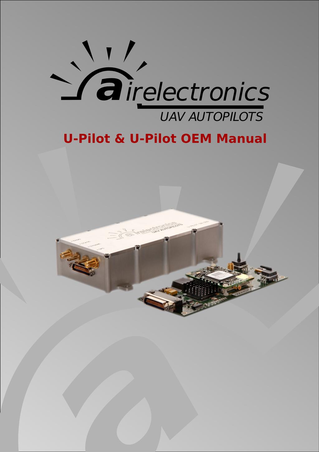
3 U- Pilot User Manual - General System troduction 1 General System troduction Airelectronics has developed a complete solution for both rotary and fixed wing UAVs. The system is composed of: U-Pilot or U-Pilot OEM U- or U- OEM U-See Software U-Pilot manages and controls the vehicle from Take-off to Landing, being capable of controlling any kind of aircraft including fixed wing, helicopters and multicopters. U-Pilot is completely capable of following a flight plan with up to 200 real-time editable points. Once the flight plan is loaded on U-Pilot, it is independent of operator instructions, and in case of a communications failure, U-Pilot starts a Return Home and Land manoeuvre which would safely land the UAV on the Runway Point. Thanks to its versatility, U-Pilot can control any payload on board the UAV such as cameras, parachutes or sensors. These devices can be real time controlled by a computer operator or by U-Pilot automatically. The FPGA technology used in U-Pilot and U- allows the system to have several logic working in parallel with the main processors. U-Pilot has working in parallel: Up to 31 PWM (Pulse-Width Modulation) or GPIO (General Purpose put / put). 3 ADC inputs (Analogical Digital Converter) to monitor the voltages of 3 batteries on the UAV. 4 serial ports RS232 to communicate with payloads, external magnetometers, etc. A radio with up to 100 km1 GPS, dynamic and static pressure sensors, a magnetometer, gyroscopes and accelerometers. U-Pilot is built using a two parallel microprocessor approach: One processor handling the state estimation and control of the UAV, using hardware acceleration to calculate high speed algorithms. A second processor handles of the mission at high level, communications with U and the Payload. The processors do not spend time handling low-level tasks, as these tasks are processed in parallel by dedicated logic of the FPGA. Due to the fact that those two processors are working in parallel and there is dedicated electronics processing the serial ports, sensors, inputs and outputs, the system is capable of recalculating its position, orientation and closing control loops at 1000 Hz. This control speed provides a great navigation accuracy and control. On the ground segment, Airelectronics has both U- and U-See. U- is a ground station that mainly acts as a relay of command and data between UPilot and U-See software. Besides acting as data relay, U- provides useful 1 Range may vary with the frequency band used. Default is 900 MHz but legal limitations in some countries may change this. 3
4 U- Pilot User Manual - General System troduction information to U-Pilot such as U- position and pressures. U- hardware is also capable of handling a Antenna tracking system. U-See software is a user friendly program that runs in any personal computer running Windows or Linux. Using U-See, the UAV operator can monitor the current state of the vehicle, control the UAV or modify the vehicle mission in real time. 1.1 Concept of system operation The system consists of an U-Pilot installed on an aircraft connected to a U- through a radio link. (See figure 1 attached below) U- has its own radio link to communicate with the U-Pilot and a RS-232 port to relay the data and command between a PC running U-See and the U-Pilot on-board the vehicle. Under certain circumstances such as aircraft integration and characterization, a Futaba Emitter is recommended in order to provide manual override of the vehicle. Figure 1: System concept The mission operation team is usually formed by two people: A External Pilot who will handle the Futaba Joystick in case a manual control of the UAV is desired (specially during the development and adjustment phase). A U-See operator that will command the mission using a computer. When using the UAV for surveillance purposes, a camera operator is recommended. 4
5 U- Pilot User Manual - Controllable Air vehicles 2 Controllable Air vehicles U-Pilot is able to control Fixed Wing and Rotary Wing vehicles. Each unit is configured for a specific type of vehicle. 2.1 Fixed wing Fixed wing can take-off automatically on a runway, hand launched or catapulted. The automatic landing can be done using a parachute or on a runway. At the time of performing the connections of the servos to the U-Pilot refer to U-Pilot connections Conventional configuration fixed wing Conventional configuration planes are supported with redundant elevator and separated channels for left and right ailerons and flaps. Other configurations/equipment are supported (spoilers support, parachute deployment for landing, etc.) upon request. Please contact us for this kind of configuration Flying wing configuration Tailless flying wing is supported and aileron control is separated in two channels per wing to improve reliability and enable usage of butterfly air-brake deployment. 2.2 Rotary wing Rotary wing configuration group different vehicles. U-Pilot can be configured for the following type (extra configuration will be added in the future) Helicopter (Swash-plate 4) The helicopter has a swash-plate driven by four servos. These servos should be connected to U-Pilot following the attached schematic. Servo 1 is forward mounted. Servo 2 is right mounted. Servo 3 is back mounted. Servo 4 is left mounted. Figure 2: Helicopter servo distribution The U-Pilot motors connection is detailed in U-Pilot connections Helicopter (Swash-plate 3) The helicopter configured as swash-plate 3 has a swash-plate driven by three servos. These servos should be connected to UPilot following the attached schematic. Servo 1 is forward-right mounted. Servo 2 is back mounted. Servo 3 is forward-left mounted. The U-Pilot motors connection is detailed in U-Pilot connections. Figure 3: Helicopter (Swash-plate 3) servo distribution 5


6 U- Pilot User Manual - Controllable Air vehicles Helicopter (Direct Drive) The helicopter has a swash-plate driven by three servos. These servos should be connected to U-Pilot following the attached schematic. Servo 1 drives cyclic pitch Servo 2 drives cyclic roll Servo 3 drives collective Note that as every movement of the swash-plate is assigned exclusively to a servo, you don't need to respect the right/left or forward/back indications of the diagram, as you can always check inverse in the servos adjustment step. Figure 4: Helicopter (direct swash plate) servo distribution The U-Pilot connections. motors connection is detailed in U-Pilot Quadcopter The quadcopter motors distribution and the rotation direction is represented in the attached schematic. The quadcopter motors distribution and the rotation direction is represented in the attached schematic. Notice that motors number 1-3 must turn clockwise and motors number 2-4 must turn anticlockwise. The U-Pilot motors connection is detailed in U-Pilot connections. Figure 5: Quadcopter motors distribution Hexacopter The hexacopter motors distribution and the rotation direction is represented in the attached schematic. Notice that motors number must turn clockwise and motors number must turn anticlockwise. The U-Pilot motors connection is detailed in U-Pilot connections. Figure 6: Hexacopter motors distribution 6

7 U- Pilot User Manual - Controllable Air vehicles Octocopter The octocopter motors distribution and the rotation direction is represented in the attached schematic. Notice that motors number must turn clockwise and motors number must turn anticlockwise. The U-Pilot motors connection is detailed in U-Pilot connections. Figure 7: Octopter motors distribution 7
8 3 U-Pilot The U-Pilot is powered in the range from 6.0V to 24V, view Power Supply. This allows the connection of UPilot directly to a 2S LiPo battery without adding possible points of failure in the system. If the system uses 6V servos, U-Pilot can be connected directly to the servo power and save weight. The power installation can be done in several different ways described in Power Supply section. U-Pilot has three ADC available channels to monitor system voltages, and it is possible to connect a HallEffect amperometer sensor to control the discharge of battery in electric UAVs. There are up to 31 PWM outputs signals at 50, 200, 300, 333 or 560Hz frequencies and 1500 or 760 us pulses. Figure 8: U-Pilot I/O Schematic PWM at 50Hz is the most common way to control servos and it will be accepted by almost any servo in the market. This signal pulses every 20 ms (milliseconds), and depending on the length of these pulses the servo will move to different positions. Digital servos (300Hz) can accept much faster control input and are the recommended choice when control rotary wing aircraft. Upon request, all the PWM lines can be reconfigured to output or input any other digital signal. There are 4 serial ports also available for additional devices use, such as cameras or magnetometers. Serial ports are automatically adapted to the baud rate of the devices connected to it. The voltage levels for the serial ports are the standard +12V/-12V. Connector pin configuration is detailed on U-Pilot Connections section. 3.1 U-Pilot and U-Pilot OEM U-Pilot can be acquired in two versions, the standard version, enclosed in an aluminium box, and the OEM version that is not enclosed, ready to be embedded into the customer system. Unless told otherwise, the explanations provided by this document are valid for both versions. When different explanations are required, this document will state it. 3.2 Power supply U-Pilot power supply accepts voltages in a range from 6.0V to 24V. Main power voltage is directly connected to the ADC channel number 4, thus allowing monitor of AP battery and 8
 CAUTION: Power the Autopilot at a voltage OUT of range can cause IRREVERSIBLE DAMAGE to")
9 check for voltage supply stability. This level is displayed as an internal battery 4 on the USee state window (Consult U-See manual for details) CAUTION: Power the Autopilot at a voltage OUT of range can cause IRREVERSIBLE DAMAGE to the system. Please read carefully this manual and do not hesitate to contact us ( if needed. Typical power consumption about 4 Watt, but the power system should be prepared to withstand 7 Watts peaks. This consumption will mean an intensity consumption of 0.8 Amp. at 6V or 0.4 Amp. at 12 V. 3.3 Monitoring Engine Data A better estimation of the battery status on electric vehicles is available by adding an amperometer connected to the ADC3 on the U-Pilot. The amperometer is a linear hall effect sensor supplied by Airelectronics. This configuration allows the user to improve the efficiency of the flight. For further information of its usage check the Engine Data section of the U-See manual. 3.4 Microprocessors structure The Autopilot has two microprocessors (CPUs). CPU Mission control. This CPU manages Communications to and from ground segment, the management of payloads and, in general, operations that are not flight related. CPU Flight control. This CPU produces the surfaces commands and control the attitude of the aircraft. This processor access all its sensors in a non-blocking way and it is always evaluating current position, attitude and control. Figure 9: General system architecture. 3.5 Sensors There are several sensors inside U-Pilot and all of them have their own electronics design inside the system taking care of them, this gives the highest reliability and performance to the system. The sensors are: 9
10 Accelerometers Gyroscopes GPS with Satellite Based Augmentation System Several Static Pressure Sensor to improve accuracy in different altitude ranges. Several Dynamic Pressure Sensors for higher accuracy during take-off and landing operations. Different sensors account for different speed segments of the mission. These sensors are only used in Fixed Wing UAVs Besides these internal sensors, for rotary wing we use an external magnetometer. It is connected to the system through RS-232 port and interfaces with dedicated electronics in U-Pilot. Due to the fact that this sensor is external it can be placed far from any electromagnetic noise inside the UAV. However, it must be connected to the proper main connector on U-Pilot. (See section 3.6) If, for some reason, a external dynamic pressure sensor is needed, the system has the provisions to make use of an Airelectronics external I2C sensor that can be mounted separately from U-Pilot. This sensor is only provided upon request. The sensor suite is very flexible and can be modified to reflect a customer requirement on the system. 10
11 3.6 U-Pilot Connections This section provides the required information about U-Pilot connections, including: Main connector connections Pressure connections Radio-Link connections GPS antenna connections. Magnetometer connections U-Pilot Main Connector The aerial part of connector used for the U-Pilot is provided in the stallation Kit. Cables in the aerial connector are colour coded. The following table describes the function of every pin in the main connector in U-Pilot and the corresponding colour coded cable in the supplied aerial connector. The pin configuration used depending on the UAV vehicle is detailed in the following table and the corresponding connector diagram. NOTE: Please, take into account than in these tables, Tx and Rx suffix are referred to UPilot. This is: a line marked as Magnetometer Rx is the pin dedicated to receive data from the magnetometer, and thus, must be connected to the sending pin in the magnetometer connector. Figure : Main connector on U-Pilot as seen from the front. 11
12 PIN I/O FixedWing Flying Wing DC in GND ADC 2 ADC 1 / Battery ADC 2 ADC 1 / Battery 5 Engine ECU Rx Engine ECU Rx GND GND Engine ECU Tx Engine ECU Tx Engine Kill Engine Kill DGPS Rx DGPS Rx DGPS Tx DGPS Tx 1-Wire 1-Wire / Temperature Temperature Sensor Sensor Payload Tx Payload Tx Payload Rx Payload Rx GND SerialBus SerialBus RS232 Port 1 Tx RS232 Port 1 Tx RS232 Port 1 Rx RS232 Port 1 Rx ADC 3 / ADC 3 / Amperimeter Amperimeter DC in Camera Pan Camera Pan Camera Tilt Camera Tilt Camera Roll Camera Roll Camera Shutter Camera Shutter Payload TTL Payload TTL Payload TTL Payload TTL SerialBus SerialBus Elevator 3 Elevator 4 Langind Gear Langind Gear Left Wheel Brake Right Wheel Brake DGPS-TTL DGPS-TTL Correction Correction GND Throttle Throttle Right Aileron Right aileron Elevator Left aileron Rudder Rudder Left Aileron Left aileron Left Flap Left Flap Elevator 2 Right Aileron Right Flap Right Flap Nose Wheel Nose Wheel 2nd Aileron Right 2nd Aileron Left 2nd Flap Right 2nd Flap Left Parachute Parachute Helicopter Swash-plate 4 Helicopter Swash-plate 3 Helicopter Direct Swashplate ADC 2 ADC 1 / Battery Magnetometer Rx Magnetometer Tx Engine Kill DGPS Rx DGPS Tx 1-Wire Temperature Sensor Payload Tx Payload Rx SerialBus RS232 Port 1 Tx RS232 Port 1 Rx ADC 3 / Amperimeter Camera Pan Camera Tilt Camera Roll Camera Shutter Payload TTL Payload TTL SerialBus Langind Gear DGPS-TTL Correction Throttle Swash-plate 1 Swash-plate 2 Tail Servo Swash-plate 3 Swash-plate 4 Parachute ADC 2 ADC 1 / Battery Magnetometer Rx Magnetometer Tx Engine Kill DGPS Rx DGPS Tx 1-Wire Temperature Sensor Payload Tx Payload Rx SerialBus RS232 Port 1 Tx RS232 Port 1 Rx ADC 3 / Amperimeter Camera Pan Camera Tilt Camera Roll Camera Shutter Payload TTL Payload TTL SerialBus Langind Gear DGPS-TTL Correction Throttle Swash-plate 1 Swash-plate 2 Tail Servo Swash-plate 3 Parachute ADC 2 ADC 1 / Battery Magnetometer Rx Magnetometer Tx Engine Kill DGPS Rx DGPS Tx 1-Wire Temperature Sensor Payload Tx Payload Rx SerialBus RS232 Port 1 Tx RS232 Port 1 Rx ADC 3 / Amperimeter Camera Pan Camera Tilt Camera Roll Camera Shutter Payload TTL Payload TTL SerialBus Langind Gear DGPS-TTL Correction Throttle Cyclic Pitch Cyclic Roll Tail Servo Collective Parachute Cable Colour Brown Red Orange Yellow Green Blue Purple Grey White Brown Red Orange Yellow Green Blue Purple Grey White Brown Red Orange Yellow Green Blue Purple Grey White Brown Red Orange Yellow Green Blue Purple Grey White Brown Red Orange Yellow Green Blue Purple Grey White 12
13 PIN I/O Quadcopter Hexacopter Octocopter Cable Colour DC in GND GND GND / GND DC in GND AADC 2 ADC 1 / Battery Magnetometer Rx Magnetometer Tx Engine Kill DGPS Rx DGPS Tx 1-Wire Temperature Sensor Payload Tx Payload Rx SerialBus RS232 Port 1 Tx RS232 Port 1 Rx ADC 3 / Amperimeter Camera Pan Camera Tilt Camera Roll Camera Shutter Payload TTL Payload TTL SerialBus Langind Gear Motor 1 Motor 2 Motor 3 Motor 4 Nose Wheel ADC 2 ADC 1 / Battery Magnetometer Rx Magnetometer Tx Engine Kill DGPS Rx DGPS Tx 1-Wire Temperature Sensor Payload Tx Payload Rx SerialBus RS232 Port 1 Tx RS232 Port 1 Rx ADC 3 / Amperimeter Camera Pan Camera Tilt Camera Roll Camera Shutter Payload TTL Payload TTL SerialBus Langind Gear Motor 1 Motor 2 Motor 3 Motor 4 Motor 5 Motor 6 Nose Wheel ADC 2 ADC 1 / Battery Magnetometer Rx Magnetometer Tx Engine Kill DGPS Rx DGPS Tx 1-Wire Temperature Sensor Payload Tx Payload Rx SerialBus RS232 Port 1 Tx RS232 Port 1 Rx ADC 3 / Amperimeter Camera Pan Camera Tilt Camera Roll Camera Shutter Payload TTL Payload TTL SerialBus Langind Gear Motor 1 Motor 2 Motor 3 Motor 4 Motor 5 Motor 6 Motor 7 Motor 8 Nose Wheel Brown Red Orange Yellow Green Blue Purple Grey White Brown Red Orange Yellow Green Blue Purple Grey White Brown Red Orange Yellow Green Blue Purple Grey White Brown Red Orange Yellow Green Blue Purple Grey White Brown Red Orange Yellow Green Blue Purple Grey White 13
14 3.6.2 Pressure sensors connections U-Pilot has two pressure sensors: Static pressure sensor Dynamic pressure sensor For fixed wing vehicles, static and dynamic pressure sensors are required. For rotary wing vehicles only static pressure sensor is required. The static pressure tap may be left unconnected if U-Pilot environment is not sealed or pressurized. Otherwise it must be connected to the ambient pressure. The dynamic pressure must be connected to a pitot tube, installed away from turbulent flows such as propeller down-wash. The pressure connection installations differ in U-Pilot and U-Pilot OEM. Depending on your U- version, you have to refer to the apropriate subsection U-Pilot (Box) pressure connections U-Pilot pressure connectors are properly labelled on the front face of the box: STATIC for static pressure and DYNAMIC for dynamic pressure. The static pressure sensor can be left unconnected if U-Pilot environment is not pressurized or sealed U-Pilot OEM pressure connections The OEM version of U-Pilot exposes directly the pressure sensors. The sensors can be identified with the image. The static pressure sensor can be left unconnected if UPilot environment is not pressurized or sealed. Figure 10: Pressure sensors The dynamic pressure (pitot) must be connected to the lower conduit of the sensor. The upper conduit must be connected to the static tap, and may be left unconnected under the same circumstances as the static sensor Radio-link antenna connections The radio-link antenna connection depends on the version of U-Pilot. Depending on your U version, please refer to the apropriate subsection U-Pilot (Box) Radio-link connection The radio-link antenna must be connected to U-Pilot with an SMA-connector to the connector labelled as RADIO in the front face of U-Pilot box U-Pilot OEM Radio-link connection The radio-link antenna must be connected to the radio-module using and MMCX connector GPS antenna connections The GPS antenna installation depends on the version of U-Pilot. Depending on your U version, please refer to the apropriate subsection. 14

15 U-Pilot (Box) GPS connection The GPS antenna must be connected to U-Pilot with an SMA-connector to the connector labelled as GPS in the front face of U-Pilot box U-Pilot OEM GPS connection U-Pilot OEM has two GPS connectors: UFL connector. SMA connector. The GPS antenna can be connected to any of the two connectors but NOT BOTH. The location of the UFL and SMA connectors is described in the mechanical drawings for the OEM version Magnetometer connections For rotary wing platforms, it is need to connect an external magnetometer to U-Pilot. It is encased in metal and it interfaces and powers through a DB9 connector. Figure 11 and Table 1 detail the proper wiring to connect the magnetometer to U-Pilot. Note, through, that this magnetometer must be supplied with DC between 6.5V and 15V. Magnetometer PIN Magnetometer Function Connected to 2 TxD Pin 5 (Magnetometer RX in main connector) 3 RxD Pin 6 (Magnetometer TX in main connector) 5 GND Vcc Magnetometer power supply. (6.5V-15V) Figure 11: Magnetometer connector viewed from the front. 9 Table 1: Magnetometer connection list Magnetometer configuration For correct operation with U-Pilot system, the HMR2300 magnetometer must be configured to use: binary output continuous measurement zero offset turned Off averaging Off Auto S/R pulses On Re-Enter responses On 50 samples per ID Set to 0 15
16 You can check configuration query command answer from the magnetometer against the following response: BINARY, CONTIN, S/R ON, ZERO OFF, AVG OFF, R ON, ID= 00, 50 sps A Correctly configured magnetometer should answer with an identical string.(configuration can be queried with the command *99Q) You can check how to enable this configuration in the HMR2300 Magnetometer command sequence on page 22 or in the magnetometer manual. 16
17 Appendix A Box Mechanical Drawing 17
18 Appendix B OEM Mechanical Drawing 18
19 Appendix C Guide for determining servo reverse When a new vehicle is configured with U-Pilot and U-See it is needed to determine if Reverse check-box should be active. Follow the following tables to determine if your servos need reversal. Fixed Wing servos2 Conventional configuration Servo Min commanded action Max Commanded action Throttle Carburator closed Carburator opened Aileron Right Right aileron trailing edge up Right aileron trailing edge down Elevator Elevator trailing edge up Elevator trailing edge down Rudder Rudder trailing edge right Rudder trailing edge left Aileron Left Left aileron trailing edge down Left aileron trailing edge up Wheel Steer right Steer left Servo Min commanded action Max Commanded action Throttle Carburator closed / motor stopped Carburator opened / motor at max speed ward Left aileron Left aileron trailing edge down Left aileron trailing edge up ward Left Aileron Left aileron trailing edge down Left aileron trailing edge up Rudder Rudder trailing edge right Rudder trailing edge left ward Right Aileron Right aileron trailing edge up Right aileron trailing edge down ward Right Aileron Right aileron trailing edge up Right aileron trailing edge down Wheel Steer right Steer left Flying Wing Helicopter Servos When referring the swash-plate, left/right/front/back will be always referred as watching the swash-plate from above and in the direction of forward movement of the vehicle Direct Servos Servo Min commanded action Max Commanded action Throttle Carburator closed Carburator opened Collective Full Swash-plate down Full Swash-plate up Swash-plate tilts right Swash-plate tilts left Cyclic Pitch Swash-plate tilts backwards Swash-plate tilts forward Rudder Tail rotor acts to make tail rotates clockwise Tail rotor acts to make tail rotates anticlockwise Cyclic Roll 2 This section assumes conventional aircraft configuration. Canard configurations require different settings, please contact Airelectronics if that's your case 19
20 Swash-plate 4 Servo Min commanded action Max Commanded action Throttle Carburator closed Carburator opened Swash-plate 1 moves down moves up moves down moves up Swash-plate 3 moves down moves up Swash-plate 4 moves down moves up Rudder Tail rotor acts to make tail rotates clockwise Tail rotor acts to make tail rotates anticlockwise Min commanded action Max Commanded action Swash-plate 2 Swash-plate 3 Servo Throttle Carburator closed Carburator opened Swash-plate 1 moves down moves up moves down moves up Swash-plate 3 moves down Corresponding swash plate section moves up Rudder Tail rotor acts to make tail rotates clockwise Tail rotor acts to make tail rotates anticlockwise Servo Min commanded action Max Commanded action Engine 1 Engine 2 Servo Min commanded action Max Commanded action Engine 1 Engine 2 Engine 4 Engine 5 Engine 6 Swash-plate 2 Quadcopter Engine 3 Engine 4 Hexacopter Engine 3 20
21 Octocopter Servo Min commanded action Max Commanded action Engine 1 Engine 2 Engine 6 Engine 4 Engine 5 Engine 6 Engine 7 Engine 8 21
22 Appendix D HMR2300 Magnetometer command sequence To configure the magnetometer for use with U-Pilot system you may use the following command sequence. For doing this, you will need to prepare a special DB-9 connector that includes the power for the magnetometer and connect to the magnetometer using a RS232 terminal program, like putty, windows hyperterminal or minicom. Default factory setting for HMR2300 is N1 while a magnetometer configured for UPilot will be at N1. *99WE *99B *99WE *99TN *99WE *99ZF *99WE *99VF *99WE *99ID=00 *99WE *99R=50 *99WE *99!BR=F *99WE *99C *99WE *99SP (This last command puts magnetometer serial interface into bauds, so if you started at 9600 as it is the default, you should change your serial terminal settings accordingly) (This command puts the magnetometer in continous measurement mode, so the terminal output will fill with binary data and the following two commands may be necessary to input blindly) After this final step, you should be able to power cycle the magnetometer and check that it starts giving binary output at start-up. For more detail about the meaning of these commands, please, refer to the Magnetometer user manual. 22
23 Appendix E Changelog This annex describes changes introduced to this document. Date Changes 2017/04/05 Version 1.30 Updated connection tables. 2017/03/13 Version up to 1.29 Updated the connection tables. Version of document up to 1.28 Added description of HMR2300 correct configuration for usage with U-Pilot system Added an appendix with correct command sequence for proper confoguration of HMR2300 magnetometer. 2015/07/04 Version of document up to 1.27 Updated pin connections in magnetometer section Updated direction of some pins of main conector. 2015/06/23 Version of document up to 1.26 Changed pin connections for RS232 Port 1. Changed pin connections for Payload Tx/Rx. 2015/02/19 Version of document up to 1.25 Changed wrong aileron sense for Flying wing. Added GPS, Pressure and Radio-Link connections. Added mechanical drawings for Box and OEM versions 2014/10/27 Version of document started 0.5 Created Document 2015/07/14 If you need a previous info@airelectronics.es version of documentation, please, contact us at 23
UAV KF-1 helicopter. CopterCam UAV KF-1 helicopter specification
 UAV KF-1 helicopter The provided helicopter is a self-stabilizing unmanned mini-helicopter that can be used as an aerial platform for several applications, such as aerial filming, photography, surveillance,
Length Height Rotor Diameter Tail Rotor Diameter..12. Tail Boom Length Width
 2.1 Air Vehicle 2.1.1 Vehicle General Description The PA-01 Vapor S-UAV is a rotary wing small unmanned aerial vehicle. The AV is powered by an outrunner 8.5hp class brushless electric motor. The airframe
FC151. FC151 Flight Control System Instruction Manual. #21436
 Shanghai Dualsky Models co.,ltd. Rm.1016,No.201,Xin Jin Qiao Rd.,Shanghai,China. Tel: +86 21 50322162 Fax: +86 21 50322163 Flight Control System Instruction Manual Made in China 41ZX15F0810 #21436 http://www.dualsky.com
Caution Notes. Features. Specifications. Installation. A3 3-axis Gyro & Stabilizer User Manual V1.0
 Caution Notes Thank you for choosing our products. If any difficulties are encountered while setting up or operating it, please consult this manual first. For further help, please don t hesitate to contact
DSSI UAV. Unmanned Aerial Vehicle. Research & Development Project
 UAV Unmanned Aerial Vehicle HISTORY AND SKILLS of Small UAV with electrically powered propeller Description of the solution: Airframe,electronics, 2 battery sets 1 spare Airframe, battery charger Transport
BlackWidow Flybarless System Manual And Setup Guide
 BlackWidow Flybarless System Manual And Setup Guide Table of contents. 1. BlackWidow System Overview 2. Power Supply 3. Transmitter Settings 4. Blackwidow to Receiver Connections 5. Servo Connections 6.
30A BLDC ESC. Figure 1: 30A BLDC ESC
 30A BLDC ESC Figure 1: 30A BLDC ESC Introduction This is fully programmable 30A BLDC ESC with 5V, 3A BEC. Can drive motors with continuous 30Amp load current. It has sturdy construction with 2 separate
Y. Lemmens, T. Benoit, J. de Boer, T. Olbrechts LMS, A Siemens Business. Real-time Mechanism and System Simulation To Support Flight Simulators
 Y. Lemmens, T. Benoit, J. de Boer, T. Olbrechts LMS, A Siemens Business Real-time Mechanism and System Simulation To Support Flight Simulators Smarter decisions, better products. Contents Introduction
BY HOEYCOMB AEROSPACE TECHNOLOGIES. HC-330 HYBRID-POWERED ALL- ELECTRICITY DRIVEN four-rotor UAV
 BY HOEYCOMB AEROSPACE TECHNOLOGIES HC-330 HYBRID-POWERED ALL- ELECTRICITY DRIVEN four-rotor UAV Content SYSTEM SPECIFICATI- ON TYPICAL USING PROCESS OVERVIEW SUBSYSTEM SPECIFICATI- ON 1 OVERVIEW System
Warning! Before continuing further, please ensure that you have NOT mounted the propellers on the MultiRotor.
 Mission Planner Setup ( optional, do not use if you have already completed the Dashboard set-up ) Warning! Before continuing further, please ensure that you have NOT mounted the propellers on the MultiRotor.
Bild : Bernhard Mühr German Aerospace Center Flight Operations
 German Aerospace Center Flight Operations Bild : Bernhard Mühr www.wolkenatlas.de Introduction DLR is Germany s aerospace research center and space agency with about 4700 employees in 31 research institutes
SK-GPS Instruction Manual. Rev August 1, 2014
 SK-GPS Instruction Manual Rev. 1.10 August 1, 2014 Table of Contents Safety...1 Box Contents...2 Getting Started...3 SK-GPS Internal Blue LED States...3 Swash Bump at Init...3 Mounting the SK-GPS...4 Connecting
AERO. Meet the Aero. Congratulations on your purchase of an Aero!
 AERO Congratulations on your purchase of an Aero! Please read the following sections of this manual to get started with your new autonomous aircraft. 1 Meet the Aero 7 Fly-by-wire mode 2 Safety 8 Command
Super Squadron technical paper for. International Aerial Robotics Competition Team Reconnaissance. C. Aasish (M.
 Super Squadron technical paper for International Aerial Robotics Competition 2017 Team Reconnaissance C. Aasish (M.Tech Avionics) S. Jayadeep (B.Tech Avionics) N. Gowri (B.Tech Aerospace) ABSTRACT The
ROBUST AIRFRAME FOR UAV FLIGHT TESTING FOR SALE!
 ROBUST AIRFRAME FOR UAV FLIGHT TESTING FOR SALE! My team specializes in fabricating airframes that s appropriate for testing unmanned aerial vehicle components. Our airframes are made of hybrid composite
Formation Flying Experiments on the Orion-Emerald Mission. Introduction
 Formation Flying Experiments on the Orion-Emerald Mission Philip Ferguson Jonathan P. How Space Systems Lab Massachusetts Institute of Technology Present updated Orion mission operations Goals & timelines
Section 1: List of Configurations Currently Approved:
 Section 1: List of Configurations Currently Approved: 1. Configuration: TD2 BASIC-Standard - Single Engine, Land, Optional Fixed or Retractable Gear, Optional Fixed Pitch or Constant Speed Propeller, Optional
S.E.V Solar Extended Vehicle
 S.E.V Solar Extended Vehicle EEL 4914 Senior Design II Group #4 Hamed Alostath Daniel Grainger Frank Niles Sergio Roig Motivation The majority of electric motor RC planes tend to have a low flight time
Investigative Technologies and Techniques
 Investigative Technologies and Techniques Using Drones In Accident Investigation (Aerial Photography) Drone used in accident investigation Technical specifications and performance Flat 8 motor configuration
Electric Penguin s philosophy:
 UNMANNED PLATFORMS AND SUBSYSTEMS Datasheet v 1.1 Penguin BE Electric Unmanned Platform Up to 110 minutes of endurance 2 with 2.8 kg payload 23 liters of payload volume Quick replaceable battery cartridge
RC Engine-EFI. Installation Manual
 RC Engine-EFI RC Engine Electronic Fuel Injection -- Conversion Kit For 120cc to 300cc engines Installation Manual ECOTRONS V1.2.3 http://www.ecotrons.com/ COPY RIGHTS ECOTRONS LLC ALL RIGHTS RESERVED
YS-X4 Multirotor Flight Controller-Hobby
 YS-X4 Multirotor Flight Controller-Hobby Part I-General Introduction YS-X4 Autopilot system for multirotors continued the innovationality/practicality/convenience style of Zero UAV's products, applied
OSPERY FPV RACER. Instruction Manual. Dynamic Rotor Tilting Quadcopter. [Version 1.0]
![OSPERY FPV RACER. Instruction Manual. Dynamic Rotor Tilting Quadcopter. [Version 1.0]](/thumbs/77/76280844.jpg "OSPERY FPV RACER. Instruction Manual. Dynamic Rotor Tilting Quadcopter. [Version 1.0]") OSPERY FPV RACER Instruction Manual [Version 1.0] Dynamic Rotor Tilting Quadcopter INTRODUCTI Congratulations on your choice of the SkyRC OSPERY FPV Racer. This is a high performance quadcopter with FPV
OSPERY FPV RACER Instruction Manual [Version 1.0] Dynamic Rotor Tilting Quadcopter INTRODUCTI Congratulations on your choice of the SkyRC OSPERY FPV Racer. This is a high performance quadcopter with FPV
AERO. Meet the Aero. Congratulations on your purchase of an Aero!
 AERO Congratulations on your purchase of an Aero! Please read the following sections of this manual to get started with your new autonomous aircraft. 1 Meet the Aero 7 Fly-by-wire mode 2 Safety 8 Command
1.1 REMOTELY PILOTED AIRCRAFTS
 CHAPTER 1 1.1 REMOTELY PILOTED AIRCRAFTS Remotely Piloted aircrafts or RC Aircrafts are small model radiocontrolled airplanes that fly using electric motor, gas powered IC engines or small model jet engines.
Welcome to VBar Express 5.3
 Bar Express Welcome to VBar Express 5.3 The VBar with V 5.3 Express software is an innovative product setting new standards for model helicopters in terms of flight performance and programming capacity.
2232 S 024 BX4 CSD/CCD 24 12,4 6,4 67,7 2 / 17 4,1 / ball bearings, preloaded 0,015. stainless steel 77 electronically reversible
 NEW Brushless DC-Servomotor with integrated Motion Controller and or CN interface 18 mnm For combination with Gearheads: 22F, 22/7, 26 2232... BX4 CSD/CCD 1 2 3 4 Nominal voltage Terminal resistance, phase-phase
In 2003, A-Level Aerosystems (ZALA AERO) was founded by current company President Alexander Zakharov, since then he has led
 was founded by current company President Alexander Zakharov, since then he has led") A-Level Aerosystems In 2003, A-Level Aerosystems (ZALA AERO) was founded by current company President Alexander Zakharov, since then he has led the company to be a leader in the micro UAV market in Russian
A-Level Aerosystems In 2003, A-Level Aerosystems (ZALA AERO) was founded by current company President Alexander Zakharov, since then he has led the company to be a leader in the micro UAV market in Russian
SP5 INSTALLATION AND SETUP MANUAL
 SP5 INSTALLATION AND SETUP MANUAL 1 Installation 1.1 Introduction The SP5 System consists of a Data Acquisition unit (DAQ) with two complete Roller control channels, each Roller Control Channel consists
Overview of operation modes
 Overview of operation modes There are three main operation modes available. Any of the modes can be selected at any time. The three main modes are: manual, automatic and mappable modes 1 to 4. The MapDCCD
Design and Development of the UTSA Unmanned Aerial System ACE 1
 Design and Development of the UTSA Unmanned Aerial System ACE 1 For use in the 2010 AUVSI Student UAS Competition Ilhan Yilmaz Department of Mechanical Engineering (Team Lead) Christopher Weldon Department
FLYEYE Unmanned Aerial System
 FLYEYE Unmanned Aerial System FLYEYE Unmanned Aerial System About Flytronic FLYTRONIC is a dynamic modern engineering company focussed on developing Unmanned Aerial Systems to provide observation and reconnaissance
3242 G 024 BX4 CS/CC 24 3,6 18,2 77,3 1,6 / 12,4 9 / ball bearings, preloaded 0,015. stainless steel 370 electronically reversible
 Brushless DC-Servomotor with integrated Motion Controller and or CN interface 6 mnm For combination with Gearheads: 3/1, 32, 32/3, 32/3 S, 38/1, 38/1 S, 38/2, 38/2 S 3242... BX4 CS/CC 1 2 3 4 Nominal voltage
Assembly and Operating Manual HR-100. Specification: *Length: 41-7/10"(1060 mm) *Wing span: 49-1/5"(1250 mm) *Flying weight: 45.
 *Wing span: 49-1/5(1250 mm) *Flying weight: 45.") Assembly and Operating Manual HR-100 Specification: *Length: 41-7/10"(1060 mm) *Wing span: 49-1/5"(1250 mm) *Flying weight: 45.9 oz (1300g) Dear customer, Congratulations on your choice of a factory-assembled
Assembly and Operating Manual HR-100 Specification: *Length: 41-7/10"(1060 mm) *Wing span: 49-1/5"(1250 mm) *Flying weight: 45.9 oz (1300g) Dear customer, Congratulations on your choice of a factory-assembled
AT-10 Electric/HF Hybrid VTOL UAS
 AT-10 Electric/HF Hybrid VTOL UAS Acuity Technologies Robert Clark bob@acuitytx.com Summary The AT-10 is a tactical size hybrid propulsion VTOL UAS with a nose camera mount and a large payload bay. Propulsion
PENGUIN B UAV PLATFORM
 UNMANNED PLATFORMS AND SUBSYSTEMS Datasheet v.0 PENGUIN B UAV PLATFORM Penguin B platform ready for payload and autopilot integration 0+ hour endurance Fuel injected engine option Up to 10 kg payload capacity
ilevil 2 AW Wireless Integrated Avionics Module AD-AHRS, GPS, ADS-B 978 / 1090 MHz Receiver Instruction Manual
 ilevil 2 AW Wireless Integrated Avionics Module AD-AHRS, GPS, ADS-B 978 / 1090 MHz Receiver Instruction Manual ilevil 2 AW ADS-B ANTENNA GPS ANTENNA STATIC PRESSURE DYNAMIC PRESSURE ON/OFF SWITCH CHARGING
The most important thing we build is trust. HeliSAS Technical Overview
 The most important thing we build is trust HeliSAS Technical Overview HeliSAS Technical Overview The Genesys HeliSAS is a stability augmentation system (SAS) and two-axis autopilot that provides attitude
FIRST FLYING TECHNIQUES COCKPIT PREPARATION STARTUP TAXI
 1. Introduction FIRST FLYING TECHNIQUES COCKPIT PREPARATION STARTUP TAXI We aim to teach and demonstrate how to operate a general aviation aircraft and show some basic techniques and manoeuvres that every
Crossbow Technology, Inc. All rights reserved. Information in this document is subject to change without notice. Crossbow and SoftSensor are
 DMU User s Manual Models IMU300CA- IMU300CB- IMU300CC- IMU400CA- IMU400CB- IMU400CC- VG300CA- VG300CB- IMU600CA- VG600CA- Revision A, March 2002 Document 7430-0003-01 Crossbow Technology, Inc., 41 E. Daggett
CCPM manager. A real alternative to expensive in-transmitter mixing
 Eliminates RC system latency errors. Exploits full resolution of the RC link. Corrects for CCPM geometry errors.!7!*-!) CCPM manager A real alternative to expensive in-transmitter mixing Optionally drives
Predator B: The Multi-Role UAV
 Predator B: The Multi-Role UAV June 2002 Report Documentation Page Form Approved OMB No. 0704-0188 Public reporting burden for the collection of information is estimated to average 1 hour per response,
DESIGN AND FABRICATION OF AN AUTONOMOUS SURVEILLANCE HEXACOPTER
 Proceedings of the International Conference on Mechanical Engineering and Renewable Energy 2015 (ICMERE2015) 26 29 November, 2015, Chittagong, Bangladesh ICMERE2015-PI-208 DESIGN AND FABRICATION OF AN
Quick Start Manual 1.4
 XP3.1 WayPoint Quick Start Manual 1.4 Attention! You will need to be familiar with the correct installation, configuration and operation of the XP3.1 Autopilot before you start using XP3.1 WayPoint. 1
Dealing with customer concerns related to electronic throttle bodies By: Bernie Thompson
 Dealing with customer concerns related to electronic throttle bodies By: Bernie Thompson In order to regulate the power produced from the gasoline internal combustion engine (ICE), a restriction is used
UAV engine EFI components Specifications Manual
 UAV engine EFI components Specifications Manual -In miniature sizes - For 20cc to 300cc engines V2.1 COPY RIGHTS ECOTRONS LLC ALL RIGHTS RESERVED Http://www.ecotrons.com Note: If you are not sure about
BEC 5V/5A (GND, +V,-) Motor 3 (left) (-,-,signal) Motor 2 (right) (-,-,signal) Motor 1 (tail) (-,-,signal)
 Motor 3 (left) (-,-,signal) Motor 2 (right) (-,-,signal) Motor 1 (tail) (-,-,signal)") This guide specifically outlines how I set up my RCExplorer Tricopter V3. It is not an all covering definite guide to how you should set up your tricopter. My setup looks like this (3S): FrSky Taranis
This guide specifically outlines how I set up my RCExplorer Tricopter V3. It is not an all covering definite guide to how you should set up your tricopter. My setup looks like this (3S): FrSky Taranis
DA 35/70 EFI MIL SPEC
 DA 35/70 EFI MIL SPEC Electronic Fuel Injected Engines OWNER S MANUAL Table of Contents Section Page 1. General Safety 3 2. Un-Packing Your Engine 4 3. Getting Started 7 4. Maintenance 9 5. Absolute Ratings
USER MANUAL W ONBOARD GENERATOR SYSTEM
 80 W ONBOARD GENERATOR SYSTEM USER MANUAL 1.4 1 1. Description Onboard Generator system consists of a Generator Power Unit (GPU), belt driven industrial-grade coreless generator, mounts and wiring necessary
USER GUIDE - SUPPLEMENTAL
 USER GUIDE - SUPPLEMENTAL CONTENTS 5 Instructions for RX2702V receiver... 2 5.3 Channel connection of receiver... 2 10 Walkera V450D01 Flybarless System Setting RX2702V... 3 10.5 Flybarless system setting...
UAV engine EFI components Specifications Manual
 UAV engine EFI components Specifications Manual -In miniature sizes - For 20cc to 300cc engines V1.7 COPY RIGHTS ECOTRONS LLC ALL RIGHTS RESERVED Http://www.ecotrons.com Note: If you are not sure about
F9F-2 OPERATIONAL MANUAL
 F9F-2 OPERATIONAL MANUAL 7 different color to meet customer s choice. 2 different material F9F-2/OB: F9F-2/TB: F9F-2/YB: F9F-2/WR: F9F-2/GYR: F9F-2/GRW: F9F-2/BRY: Original Blue Tail Blue Yellow/Blue White/Red
CHAPTER 11 FLIGHT CONTROLS
 CHAPTER 11 FLIGHT CONTROLS CONTENTS INTRODUCTION -------------------------------------------------------------------------------------------- 3 GENERAL ---------------------------------------------------------------------------------------------------------------------------
Air Buzz. 32nd Annual AHS International Student Design Competition
 Air Buzz 32nd Annual AHS International Student Design Competition Faculty Advisor: Dr. Daniel Schrage, Daniel.Schrage@aerospace.gatech.edu Ezgi Selin Akdemir esakdemir@gmail.com Undergraduate Middle East
L 298/70 Official Journal of the European Union
 L 298/70 Official Journal of the European Union 16.11.2011 MODULE 12. HELICOPTER AERODYNAMICS, STRUCTURES AND SYSTEMS 12.1 Theory of Flight Rotary Wing Aerodynamics 1 2 Terminology; Effects of gyroscopic
SURVEYOR-H. Technical Data. Max speed 120 km/h. Engine power 7.2 hp. Powerplant Modified Zenoah G29E. Fuel tank volume 3.6 l
 rev. 28.10.14 * features & specifications are subject to change without notice. Technical Data Max speed 120 km/h Engine power 7.2 hp Powerplant Modified Zenoah G29E Fuel tank volume 3.6 l Payload with
TTT802 Gearshift Controller, Part # R1N-S (Standard), -P (Paddleshift)
, -P (Paddleshift)") First, Sign and Date Bln 2009-03-9 Updated, Sign and Date Bln 200-04-29 (0) User Manual TTT802 Gearshift Controller Firmware for R--N-2- TTT802 Gearshift Controller, Part # 2-620-9-RN-S (Standard), -P
First, Sign and Date Bln 2009-03-9 Updated, Sign and Date Bln 200-04-29 (0) User Manual TTT802 Gearshift Controller Firmware for R--N-2- TTT802 Gearshift Controller, Part # 2-620-9-RN-S (Standard), -P
SOKAR FPV DRONE. Quick Start Manual SkyRC Technology Co., Ltd. All Rights Reserved. Version
 SOKAR FPV DRONE Quick Start Manual Manufactured by SKYRC TECHNOLOGY CO., LTD. www.skyrc.com 2015 SkyRC Technology Co., Ltd. All Rights Reserved. Version 1.0 7504-0694-01 RoHS TABLE OF CONTENTS INTRODUCTION
DMU User s Manual IMU700CA- VG700CA- (DMU-FOG) Revision B, September 2002 Document
 Revision B, September 2002 Document") Models IMU700CA- VG700CA- (DMU-FOG) Revision B, September 2002 Document 7430-0070-01 Crossbow Technology, Inc., 41 E. Daggett Dr., San Jose, CA 95134 Tel: 408-965-3300, Fax: 408-324-4840 email: info@xbow.com,
Models IMU700CA- VG700CA- (DMU-FOG) Revision B, September 2002 Document 7430-0070-01 Crossbow Technology, Inc., 41 E. Daggett Dr., San Jose, CA 95134 Tel: 408-965-3300, Fax: 408-324-4840 email: info@xbow.com,
CHAPTER 22 AUTOPILOT
 Section Title CHAPTER 22 AUTOPILOT 22-00 Description............................................... 22.1 22-10 (Pitch) Servo Assembly...................................... 22.3 22-20 (Roll) Servo Assembly.......................................
Palos Verdes High School 1
 Abstract: The Palos Verdes High School Institute of Technology (PVIT) Unmanned Aerial Vehicle team is proud to present Condor. Condor is a hexacopter weighing in at 1664g including the 4 cell 11.1 volt,
Assembly and Operating Manual. 3D cap-232. Specification: *Length: 25-9/10"(655mm) *Wing Span: 29-3/5"(750mm) *Flying Weight: 15-9/10 oz (450g)
 *Wing Span: 29-3/5(750mm) *Flying Weight: 15-9/10 oz (450g)") Assembly and Operating Manual 3D cap-232 Specification: *Length: 25-9/10"(655mm) *Wing Span: 29-3/5"(750mm) *Flying Weight: 15-9/10 oz (450g) Dear customer, Congratulations on your choice of a factory-assembled
Assembly and Operating Manual 3D cap-232 Specification: *Length: 25-9/10"(655mm) *Wing Span: 29-3/5"(750mm) *Flying Weight: 15-9/10 oz (450g) Dear customer, Congratulations on your choice of a factory-assembled
Development of a Low Cost DIY UAV Mapping Platform
 Development of a Low Cost DIY UAV Mapping Platform James Parkes Tritan Survey CC, Engineering and Hydrographic Surveyors, Cape Town, South Africa +27 21 797 2081 - jamesp@tritan.co.za Abstract In the past
Friday, 27 June Realizing a small UAV for medical transport in developing countries Master thesis: Ferdinand Peters. Dr.One
 Dr.One Friday, 27 June 2014 Realizing a small UAV for medical transport in developing countries Master thesis: Ferdinand Peters 1 Definition Drone (bee) From Wikipedia, the free encyclopedia Drones are
A complete hybrid VTOL autopilot solution. Start anywhere, fly everywhere.
 Key Features A complete hybrid VTOL autopilot solution. Start anywhere, fly everywhere. Supported Vehicle Types s Multirotors Fixed-wings Bi-, tri- and quadcopter tailsitters, quadplanes and tiltrotors.
Ace Waypoint User Manual
 Ace Waypoint User Manual Ver. 2.5 http://www.dji-innovations.com 2012 DJI Innovations. All Rights Reserved. 1 Copyrights This product and manual are copyrighted by DJI Innovations with all rights reserved.
A SOLAR POWERED UAV. 1 Introduction. 2 Requirements specification
 A SOLAR POWERED UAV Students: R. al Amrani, R.T.J.P.A. Cloosen, R.A.J.M. van den Eijnde, D. Jong, A.W.S. Kaas, B.T.A. Klaver, M. Klein Heerenbrink, L. van Midden, P.P. Vet, C.J. Voesenek Project tutor:
Glow Plug for E Series Only
 Charging the Battery - Do not charge the battery, with a charger using negative discharge pulses, when connected to the ECU. This will destroy the electronics of the ECU. The only method is to disconnect
Version 3.0 INSTRUCTION MANUAL
 Version 3.0 INSTRUCTION MANUAL 1 BEASTX be absolute stable Version 3.0 INSTRUCTION MANUAL 4 CONTENTS CONTENTS... 4 SAFETY NOTES... 6 GENERAL INFORMATION... 8 1. INTRODUCTION... 9 2. BOX CONTENT... 10
FIRE PHOENIX RADIO CONTROLLED AIRPLANE
 FIRE PHOENIX RADIO CONTROLLED AIRPLANE ASSEMBLY AND OPERATION INSTRUCTIONS YIN YAN MODEL TECH. MFT. 1 SPECIFICATIONS Material EPO Plane Battery Li-Po 1300mAh 11.1V Radio 4 Channel Wing Span 1200mm Length
Unidrive M400 Fast set-up and diagnostics with real-text display, integrated PLC and safety inputs
 Unidrive M400 Fast set-up and diagnostics with real-text display, integrated PLC and safety inputs 0.25 kw - 110 kw (0.33 hp - 150 hp) 100 V 200 V 400 V 575 V 690 V Unidrive M400 features Optional AI-485
Thank you for purchasing our product. Please enter the DJI special website of PHANTOM to confirm if the
 PHANTOM Содержание Disclaimer & Warning 2 Before You Start 2 In the box 2 Owned Tools 3 Introduction 4 Aircraft & TX Basic Operation 5 Before Flying 6 Flight Test 9 Enhanced Fail safe 10 Low voltage Alarm
Development, Certification, and Flight Testing of an OPA for UAS FTT Development and Training at NTPS
 Development, Certification, and Flight Testing of an OPA for UAS FTT Development and Training at NTPS 2013 SFTE/SETP Flight Test Symposium Evolution of Flight Testing from Manned Vehicles to UAVs 1 Overview
UAV EFI components In miniature sizes
 UAV EFI components In miniature sizes For small 2 and 4 stroke engines in 20cc- 200cc ranges V1.5 ECOTRONS LLC 2016/1 Copyright Ecotrons All rights reserved Contents 1. UAV EFI System Overview... 2 1.1
THE FALCON REDUNDANCY HIGH WIND TOLERANCE BEST USED FOR SURVEILLANCE & SECURITY DELIVERY & TRANSPORT
 THE FALCON REDUNDANCY HIGH WIND TOLERANCE The Falcon's new air frame and motor configuration is the new best in its class of light payloads with flight times of up to 50 minutes. This makes the Falcon
VG700AA User s Manual
 VG700AA- (DMU-FOG-AUTO) Rev. A, September 2002 Document 7430-0074-01 2002-2003 Crossbow Technology, Inc. All rights reserved. Information in this document is subject to change without notice. Crossbow
Flymentor 3D. User Manual SHENZHEN KDS MODEL TECHNOLOGIES CO.,LTD
 WWW.KDSMODEL.COM User Manual SHENZHEN KDS MODEL TECHNOLOGIES CO.,LTD Flymentor 3D Foreward Caution 1. Summary 1.1 Introducing 1.2 Specification 1.3 Attentions 1.4 LED status 1.5 Using flow 2. Connect to
* Ql! ^0f. B-17 Flying Fortress. 3 axis stabilization
 G3&nw * Ql! ^0f B-17 Flying Fortress 3 axis stabilization (HK)EASYSKY ENTERPRISE LIMITED Website: www.easy-sky.net E-mail: rcmodel@easy-sky.net sales@easy-sky.net Tel: 86-755-27891 659 Fax:86-755-27372071
PHOENIX HV Features of the Phoenix HV-45 : 2.3 Connecting the Motor. 2.4 Reversing Rotation. 2.5 Connecting the Receiver
 PHOENIX HV -45 1.0 Features of the Phoenix HV-45 : Extremely Low Resistance (.003 ohms) High rate adjustable switching (PWM) Up to 45 Amps continuous current Dual Opto-Coupled (No BEC) Up to 36 cells or
Brief introduction
 P-51D MUSTANG Brief introduction----------------------------------------------------------------------------03 Specifications---------------------------------------------------------------------------------03
Skycar Flight Control System Overview By Bruce Calkins August 14, 2012
 Skycar Flight Control System Overview By Bruce Calkins August 14, 2012 Introduction The Skycar is a new type of personal aircraft that will rely on directed thrust produced by its engines to enable various
Mercury VTOL suas Testing and Measurement Plan
 Mercury VTOL suas Testing and Measurement Plan Introduction Mercury is a small VTOL (Vertical Take-Off and Landing) aircraft that is building off of a quadrotor design. The end goal of the project is for
FlameWheel 450. User Manual V Revision
 FlameWheel 450 User Manual 2015.05 Revision V2.2 Disclaimer Read this disclaimer carefully before using FlameWheel 450. By using this product, you hereby agree to this disclaimer and signify that you have
SP4 DOCUMENTATION. 1. SP4 Reference manual SP4 console.
 SP4 DOCUMENTATION 1. SP4 Reference manual.... 1 1.1. SP4 console... 1 1.2 Configuration... 3 1.3 SP4 I/O module.... 6 2. Dynamometer Installation... 7 2.1. Installation parts.... 8 2.2. Connectors and
V - Speeds. RV-10 V fe Flaps Speeds Trail (0 deg) Half (15 deg) Full (30 deg) 122 kias 96 kias. 80 kias
 Half (15 deg) Full (30 deg) 122 kias 96 kias. 80 kias") RV-10 Check List V - Speeds RV-10 V fe Flaps Speeds Trail (0 deg) Half (15 deg) Full (30 deg) 122 kias 96 kias 87 kias V s1 Stall (Flap Up) 60 kias V s0 Stall (Flap 40 deg) 55 kias Best Glide 80 kias V
RV-10 Check List V - Speeds RV-10 V fe Flaps Speeds Trail (0 deg) Half (15 deg) Full (30 deg) 122 kias 96 kias 87 kias V s1 Stall (Flap Up) 60 kias V s0 Stall (Flap 40 deg) 55 kias Best Glide 80 kias V
PHANTOM 3 Standard. User Manual V
 PHANTOM 3 Standard User Manual V1.0 2015.04 Using this manual Legends Warning Important Hints and Tips Reference Read Before the First Flight Read the following documents before using the Phantom 3 Standard:
SOKAR FPV DRONE. Quick Start Manual SkyRC Technology Co., Ltd. All Rights Reserved. Version
 SOKAR FPV DRE Quick Start Manual Manufactured by SKYRC TECHNOLOGY CO., LTD. www.skyrc.com 2015 SkyRC Technology Co., Ltd. All Rights Reserved. Version 2.0 7504-0694-02 RoHS TABLE OF CTENTS INTRODUCTI INTRODUCTI
I-PNP Central Controller
 Central Controller Instructions For All PNP Models August 29, 2016 Version 2.2 BVM 2016 I-PNP Central Controller FUNCTIONS: Retract Gear (B-1) Long Press Manual Button Landing Gear Failsafe (B-2).Short
OASIS. Standby Instrument System. Installation Manual. Aerosonic Corporation September 18, N. Hercules Ave. Clearwater, FL USA
 OASIS Standby Instrument System Installation Manual Aerosonic Corporation September 18, 2012 1212 N. Hercules Ave. Clearwater, FL 33765 USA INSTALLATION MANUAL OASIS Original Aerosonic Standby Instrument
Installation Instructions for: Channel Thermocouple Amplifier
 Installation Instructions for: 30-2204 4 Channel Thermocouple Amplifier WARNING: This installation is not fo r the electrically or mechanically challenged! Use this sensor with EXTREME caution! If you
Operation Manual 3-Axis Stabilization System for Fixed Wing Model Aircraft
 Operation Manual -Axis Stabilization System for Fixed Wing Model Aircraft Table of Contents Introduction 2 Safety Instructions 2 Product Layout 2 HGXA Overview 2 LED Display Overview Specifications Features
Ejemplos de aeronaves existentes similares a las propuestas en los RFP 2007
 Ejemplos de aeronaves existentes similares a las propuestas en los RFP 2007 UAV Sergio Esteban sesteban@us.es 1 Advanced Technologies and Engineering Co (Pty) Ltd (ATE). Vulture Production: Production
Specifications ASSEMBLY INSTRUCTIONS
 ASSEMBLY INSTRUCTIONS Specifications Length : 6 mm Height : 218 mm Main Blade : 325 mm Main Rotor Diameter : 723 mm Tail Rotor Diameter : 150 mm Motor Pinion Gear : 16T (14T) Main Drive Gear : 150T Main
Control of Mobile Robots
 Control of Mobile Robots Introduction Prof. Luca Bascetta (luca.bascetta@polimi.it) Politecnico di Milano Dipartimento di Elettronica, Informazione e Bioingegneria Applications of mobile autonomous robots
UAV Enabled Measurement for Spatial Magnetic Field of Smart Rocks in Bridge Scour Monitoring
 INSPECTING AND PRESERVING INFRASTRUCTURE THROUGH ROBOTIC EXPLORATION UAV Enabled Measurement for Spatial Magnetic Field of Smart Rocks in Bridge Scour Monitoring Genda Chen, PhD. P.E., Professor and INSPIRE
STUDYING THE POSSIBILITY OF INCREASING THE FLIGHT AUTONOMY OF A ROTARY-WING MUAV
 SCIENTIFIC RESEARCH AND EDUCATION IN THE AIR FORCE AFASES2017 STUDYING THE POSSIBILITY OF INCREASING THE FLIGHT AUTONOMY OF A ROTARY-WING MUAV Cristian VIDAN *, Daniel MĂRĂCINE ** * Military Technical
Safety-TrimTM. Dual axis servo controller. with 2 speed presets
 Safety-TrimTM Dual axis servo controller Models: ST-2-12v ST-2-12v-2sp with 2 speed presets Safety-Trim is an electronic speed controller designed specifically to operate electric servo motors such as
Features: Enhanced throttle response, excellent acceleration, linearity and driveability
 120A/150A ESC X-Car 120A/150A Series Sensored/Sensorless Brushless ESC for 1:8 scale Car or Truck Thank you for purchasing the X-Car Brushless Electronic Speed Controller (ESC). The X-Car 1:8 Scale 120A/150A
PENGUIN C UAS OPERATIONS & MAINTENANCE TRAINING 20 HOURS FLIGHT ENDURANCE 100KM RANGE ITAR - FREE CREW OF TWO
 PENGUIN C UAS LONG ENDURANCE UNMANNED AERIAL SYSTEM 20 HOURS FLIGHT ENDURANCE OPERATIONS & MAINTENANCE TRAINING 100KM RANGE ITAR - FREE CREW OF TWO U AV FAC T O RY LT D., E U R O P E U AV FAC T O RY U
Advanced Information Subject to Changes
 Advanced Information Subject to Changes High Efficiency 30/60V, 100 Amps Active Management System for Lithium Ion Batteries Roboteq s is a battery management system designed for building cost-effective,