SAFETY, STORAGE, OPERATIONS AND MAINTENANCE MANUAL
|
|
|
- Claud Cobb
- 5 years ago
- Views:
Transcription


1 PUBLICATION NOVEMBER 2016
2 THIS MANUAL PROVIDES FULL INSTRUCTIONS REGARDING SAFETY, STORAGE, OPERATION, AND MAINTENANCE FOR LEAD CRYSTAL BATTERIES, AS WELL AS CERTAIN INSTALLATION CONSIDERATIONS. FAILURE TO OBSERVE THE PRECAUTIONS AS PRESENTED MAY RESULT IN DAMAGE TO EQUIPMENT, INJURY OR LOSS OF LIFE BY BETTA BATTERIES. ALL RIGHTS RESERVED. This document is proprietary to Betta Batteries. This document cannot be copied or reproduced in whole or in part, without the express written permission of Betta Batteries. PLEASE CHECK OUR WEBSITE FOR LITERATURE UPDATES.
3 GENERAL SAFETY INSTRUCTIONS SAVE THESE INSTRUCTIONS SAFETY, STORAGE, IMPORTANT! PLEASE READ THIS MANUAL. THIS MANUAL CONTAINS IMPORTANT INSTRUCTIONS THAT SHOULD BE FOLLOWED DURING STORAGE, INSTALLATION, OPERATION AND MAINTENANCE OF LEAD CRYSTAL BATTERIES. IT WILL HELP TO ACHIEVE HIGHEST PERFORMANCE OF YOUR EQUIPMENT AND EXTEND THE LIFESPAN OF YOUR PRODUCT. Battery handling and servicing should be performed- or supervised by personnel who have professional knowledge about batteries and precautionary measures. Battery replacement by unauthorized personnel is prohibited. When replacing batteries, please use Lead Crystal batteries of the same capacity and size as originals used in equipment. Do not misuse or mutilate Lead Crystal Batteries. This could result in human injury or cause damage to the batteries. In no event will Betta Batteries be responsible or liable for either indirect or consequential damage or injury that may result from misuse or mutilation of batteries. Lead Crystal Batteries contain sulphuric acid ( < 5%) Sulphuric acid can be harmful to the skin and eyes. Take precautionary measures as described in this manual. It is important to handle batteries correctly when returning batteries. As the batteries contain lead, any inappropriate handling of the batteries will have adverse effects on the environment and on persons. Please check local legislation to obtain approved handling procedures, or return batteries to authorized service centers of the manufacturer for replacements. Do not place batteries in-or near a direct fire. Do not use an organic solvent to clean batteries. Batteries may cause electric shock when short circuited. Always use tools with insulated handles when changing batteries or while performing maintenance.
4 SYMBOLS FOR BATTERY USE AND OPERATIONS PLEASE READ CHAPTER 5 FOR FURTHER DETAILED SAFETY GUIDELINES SAFETY, STORAGE, SAFETY WARNING NO OPEN FLAMES OR SPARKS ELECTRICAL HAZARD Pb RECYCLE EYE PROTECTION Pb DO NOT DISPOSE BATTERY INTO TRASH SHORT CIRCUIT PREVENTION THIS PRODUCT HAS PASSED UL SAFETY CERTIFICATION ADULT SUPERVISION THIS PRODUCT HAS PASSED CE CERTIFICATION READ THE MANUAL THIS PRODUCT HAS PASSED IEC/EN /22
5 TABLE OF CONTENTS SAFETY, STORAGE, 1 GENERAL INFORMATION 1.1 Introduction 1.2 Applications 1.3 Product Specification and Model Identification Method 1.4 Product Range 1.5 Product Standards 1.6 Advantages Summarised TECHNICAL SPECIFICATIONS 2.1 Structure characteristics Special Electrolyte Composition Battery Slot Cover Grid Partition Safety Valve Sealing Performance Positive and Negative Plates Special Manufacturing Process 2.2 Working Principle TECHNICAL SPECIFICATIONS 3.1 Charge Characteristics Volt Lead Crystal Batteries Volt Lead Crystal Batteries Volt Lead Crystal Batteries Temperature compensation Introduction EVFJ 3.2 Discharge Characteristics Battery Capacity Battery Discharge Rate Influence of Temperature on Capacity Discharge Voltage TRANSPORT, STORAGE AND 4.1 Battery Transport INSTALLATION 4.2 Battery Storage 4.3 Battery Installation MAINTENANCE 5.1 Float Applications 5.2 Battery Life and Temperature 5.3 Battery Maintenance Quarterly Maintenance Annual Maintenance SAFETY 6.1 General 6.2 Safety Equipment and Clothing 6.3 Safety Precautions Sulphuric Acid Burns Explosive Gases Electrical Shocks and Burns CUSTOMER SERVICE 31
6 1 GENERAL INFORMATION 1.1 Introduction Growing demand for batteries on a global scale Due to the rapid development of the industry, the application of batteries in transportation, communication, power, military, aviation, marine, commercial facilities as well as in the daily needs of users has become more extensive. The performance of conventional lead based batteries is not optimal Because of its inherent structural characteristics, traditional lead-acid batteries suffer from plate sulphation, active material loss, high water loss rate, serious acid pollution, poor low temperature performance, short life cycle, poor transport safety and other flaws. In order to overcome the structural weaknesses in lead-acid batteries, gel electrolyte has been used as replacement in gel batteries. Although it reduces acid mist, reduces water loss rate and self-discharge rate, and improves the discharge performance, it raises new problems such as poor penetration of the gel material, weak compatibility with the SAM (super absorbent material) separator and a slow reaction to the electrodes. By its unique technology Lead Crystal batteries have a high performance To overcome the fundamental flaws of the lead-acid and gel batteries, we have successfully developed five exclusive patented technological innovations in Lead Crystal batteries. Lead Crystal batteries are ideal products to replace lead acid and gel batteries In line with the industrial development trend of the 21st century, Lead Crystal batteries pioneered the new concept of environmentally friendlier electrolyte and manufacturing, and marked the iconic innovation of battery technology. The excellent properties of Lead Crystal batteries is well received in many provinces and cities in China, and has successfully entered markets in Southeast Asia, Africa, the Middle East, Europe and other international markets. They are widely used in solar energy, wind energy storage systems, telecommunications, UPS power supply, power stations, railway passenger cars, electric vehicles, electric bikes, beacon signal indicators and other fields. This new type of environmentally friendly product is rapidly blending into the consumer lifestyles of many industries and is widely accepted by institutions and individuals. The patented technology found in lead crystal batteries uses a special advanced technology formula, a new type of composite SiO2 electrolyte developed to completely replace traditional sulphuric acid solution. This in turn improves the product s application and safety performance. When the composite electrolyte reacts with the plates during the charging process, crystalline electrolyte salts are formed, and the electrolyte is absorbed into the electrolytic salt. The electrolyte is distributed evenly, in a non- hierarchical manner, and there is no gradient concentration in the upper and/or lower electrode. The electrical properties of the battery are consistent and achieve reliable performance. It effectively overcomes the disadvantages of plate sulphation, active material loss and water loss rate, has good low temperature and overcharge performance, and greatly improves product life.
7 1.2 Applications Lead Crystal batteries can be used in a wide range of applications where lead acid, Lead Gel batteries or SAM (super absorbent material) Batteries are used today, including, but not limited to: Telecommunications, Communications Exchange And Transmission Systems; UPS Uninterruptible Power Supply, PABX And Microwave Relay Station; Radio And Broadcasting Stations; Power Plants And Transmission Systems; Emergency Lighting Systems; Railway Signal, Beacon Signalling System; Solar Energy, Wind Energy Storage Systems; 1.3 Product Specification and Model Identification Method 6 - CN - FJ Rated capacity in Ah (Amp hours) Valve controlled, sealed lead crystal storage cell Energy storage battery Number of single cells in series 6 = 12 volt, 3 = 6 volt
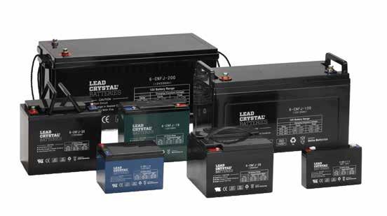
8 1.4 Product Range Article number Battery EAN code Front terminal Rated voltage Rated AH (10 hours) Weight (KG) L W H Total H 12 V range 6-HCNFJ , CNFJ , CNFJ , CNFJ , CNFJ , CNFJ , CNFJ , CNFJ , CNFJ , CNFJ , CNFJ , CNFJ-35F , CNFJ , CNFJ , CNFJ , CNFJ , CNFJ , CNFJ , CNFJ , CNFJ , CNFJ-150F , CNFJ , CNFJ , CNFT , CNFT , CNFT , CNFT , CNFT , CNFT , CNFT ,
9 Article number Battery EAN code Front terminal Rated voltage Rated AH (10 hours) Weight (KG) L W H Total H 6 V range 3-CNFJ , , CNFJ-7, ,2 1, CNFJ , CNFJ , CNFJ , CNFJ , CNFT x , Article number Battery EAN code Front terminal Rated voltage Rated AH (10 hours) Weight (KG) L W H Total H 2 V range CNFJ , CNFJ , CNFJ , CNFJ , CNFJ , CNFJ , CNFJ , CNFJ , CNFJ , CNFJ , CNFJ , CNFJ , CNFJ ,
10 Article number Battery EAN code Front terminal Rated voltage Rated AH (10 hours) Weight (KG) L W H Total H Light traction range 3-EVFJ EVFJ EVFJ EVFJ EVFJ EVFJ EVFJ EVFJ EVFJ EVFJ EVFJ EVFJ EVFJ EVFJ Product Standards Lead Crystal batteries are manufactured to meet the following national and international standards and are manufactured under the ISO 9001, ISO and GB/T system. GB/T lead-acid energy storage battery GB/T fixed type valve-controlled sealed battery Q/TDZG fixed type valve control sealed lead crystal battery BS 6290 part 4, Telcordia SR 4228, Eurobatt guide, UL, IEC /22
11 1.6 Advantages Summarised Compared to mainstream rechargeable industrial batteries like lead acid, lead gel and SAM (super absorbent material) batteries, Lead Crystal batteries perform as follows: Lead Crystal batteries can be charged faster Lead Crystal batteries can be discharged deeper (even to 0 Volt!) Lead Crystal batteries have an operating temperature from -40 to 65 Celsius Lead Crystal batteries can be charged below 0 degrees Celsius Lead Crystal batteries can be cycled more often 80% DOD) Lead Crystal batteries have very low gassing (IEC /11) Lead Crystal batteries can be used in a partial state of charge Lead Crystal batteries can be stored for 2 years without top-up charging Lead Crystal batteries hold no cadmium, no antimony and < 5%sulphuric acid Lead Crystal batteries require no special ventilation or cooling 2 TECHNICAL SPECIFICATIONS Lead Crystal batteries are a new range of products that were successfully developed reengineering existing batteries and incorporating new patented technologies. It has better performance characteristics compared to conventional batteries and is the result of new technical breakthroughs. The fundamental issues of lead acid battery pollution, electrode sulphation, short life cycle, poor low temperature performance and otherflaws are resolved, setting a high standard of "efficiency, safety, and long-life". 2.1 Structure Characteristics Special Electrolyte Composition A unique complex technology is used to synergize a range of patented inorganic salts and organic substances, thereby optimizing the reaction between the electrolyte and the active electrode material, effectively converting the active substance into a salt that prevents it from falling off the plates, extending its service life. The electrolyte within the battery crystallizes, leaving no free electrolyte, no leakage, making the battery safe and reliable. The battery may be installed using in a variety of orientations, making it easy to use. This opens a wide range of installation applications, since the risk of electrolyte leakage is eliminated. This reaction also improves the product s safety making it less harmful to installers and users alike Battery Slot Cover The battery slot cover is made from strong opaque ABS plastic with a standard V2 flammability rating. It is also available in a V0 and V1 flammability rating on order or extreme temperature resistant cases for those too hot to handle applications Grid The grid is made with high quality corrosion-resistant near pure Lead alloy (no antimony or cadmium), to ensure the excellent performance life of the positive grid, improve the over potential of the anode and inhibit hydrogen corrosion whilst posing less of a risk to the environment and the user.
12 2.1.4 Partition (SAM) The partition is made of an ultra-fine fibrous super absorbent mat (SAM) separator with greatly enhanced porosity, using cathode absorption technology to create gas recombination. The SAM separator has good acid resistance and stability, which provides sufficient porosity and maintains the smooth passage of the gas while absorbing and storing sufficient volumes of electrolyte (to ensure the battery s high performance). The oxygen can rapidly distribute negative electrons to perform cathode absorption and oxygen combination cycle. AGM vs SAM Standard AGM Aggregated Glass Matt is a material used to function as a separator between plates that assists in electrolyte distribution and also helps maintain the pasting lead s (lead Pb and lead Oxide Pb02) on the plates, AGM made partly of glass fibres tends to limit the electron flow since glass is also an insulator. Our advanced patented SAM is a super absorbent matt made entirely from non-insulating highly pores fibres, SAM absorbs electrolyte at an increased rate and holds it longer compared to AGM. SAM also becomes part of the batteries chemical reaction during cycling Safety Valve A safety exhaust valve that has high sensitivity, is used and can open or close according to the internal pressure change of the battery. Safety valves are made of corrosion-resistant, anti-aging fluorine rubber, which can retain the air-tightness and liquid-tightness of batteries with long-term use and constant open and close valve pressure. The internal pressure of the batteries is maintained at optimal safety range Sealing Performance Battery compartment and cover are seals made of rubber rings and terminals that are dual-sealed. A sealing material that has small shrinkage is used to ensure that the terminal seals well Positive and Negative Plates The positive and negative plates are the core electrochemical reaction region and the most important components of the battery. The grid is coated with lead paste and formed after curing, drying, and other processes. The following composition are the active material of the positive and negative plates: Positive electrode plate: main component - Lead Dioxide (PbO2); Negative electrode plate: main components - Spongy Lead (Pb). Betta Batteries also make RED LEAD batteries for the Aero space industries Special Manufacturing Process Using pressure filling technology in combination with patented gravity filling containers to fill the batteries with electrolyte and the patented terminal connecting equipment, these improvements ensure an even distribution of electrolyte in each cell further enhancing the performance of the batteries and increasing the efficiency.
13 2.2 Working Principle DISCHARGE PbO2 + 2H2SO4 + Pb PbSO4 + H2O + PbSO4 LEAD DIOXIDE CHARGE + DILUTE LEAD SULPHURIC + LEAD SULPHATE ACID + WATER + LEAD SULPHATE POSITIVE PLATE COMPOSITE NEGATIVE PLATE POSITIVE WATER NEGATIVE ACTIVE MATERIAL ELECTROLYTE ACTIVE MATERIAL DISCHARGE MATERIAL DISCHARGE MATERIAL Figure 2.1. The main electrochemical reaction during charge / discharge. When discharging, the positive and negative active material reacts with the acidic element of the electrolyte and becomes lead sulphate and water, causing the acid density to decrease. When charging, the acid that concentrated in the positive discharge material (during discharge cycles) is released back into the electrolyte. At this time the lead sulphate in the positive and negative plate transforms into lead dioxide and a spongy type of lead which causes the acid density in the electrolyte to increase. With conventional lead based batteries, after charging or prior to charge completion, all the charging current is used for electrolyses of the moisture in the electrolyte. The positive plates release oxygen and the negative plate hydrogen gas. If the gas recombination efficiency of the battery is low, a large percentage of the gas will escape leaving less moisture in the battery after every charge. This action causes the electrolyte content to decrease due to water loss, raising the acidity in the battery and shortening the life of the battery. This is known as late charge fluid loss phenomenon. With Lead Crystal batteries, besides the regular chemical reaction, the composite electrolyte has various additives that participate in the electrochemical reaction. The additives inhabit the oxygen and hydrogen gas during the charging cycle increasing the batteries recombination rate. This in turn reduces the water loss during and after charging. When discharging, the lead sulphate can be totally transformed back into active material, prolonging the battery s use life. Lead Crystal batteries use a new advanced type of SAM, super absorbent material as a separator. The SAM has much higher electrical conductivity, heat resistant and acid resistant abilities than standard SAM on the market. The crystallized electrolyte in combination with the SAM can effectively protect the plates and prevent the active material from falling off during use. The electrolyte is completely absorbed and stored in the SAM. Since the SAM is completely saturated with electrolyte and then crystallized, no free liquid electrolyte will be present in the battery. The battery can now be used in various directional positions without leaking.
14 3 CHARGE AND DISCHARGE SPECIFICATIONS 3.1 Charge Characteristics See below charge characteristics for CNFJ, HCNFJ and CNFT Lead Crystal Batteries volt Lead Crystal Batteries Charge Curves 12 volts CYCLE CHARGE CHARACTERISTIC (25 C) REGULAR CYCLE CHARGE CHARACTERISTICS 77 F (25 C) CHARGE CAPACITY (%) CHARGING CURRENT (CA) CHARGING VOLTAGE (V) CHARGING VOLTAGE CHARGE CAPACITY CHARGING CURRENT TIME (H) FLOATING CHARGE CHARACTERISTIC (25 C) F L OATING CHA RGE C H ARAC TERI STIC S 7 7 F ( 2 5 C ) CHARGE CAPACITY (%) CHARGING CURRENT (CA) CHARGING VOLTAGE (V) CHARGING VOLTAGE CHARGE CAPACITY CHARGING CURRENT T IME (H) Charger Settings Lead Crystal Batteries are high-end products that work best with good quality battery chargers. For our range of Lead Crystal Chargers, visit
15 volt Lead Crystal Batteries Charge Curves 6 volts CYCLE CHARGE CHARACTERISTIC (25 C) REGULAR CYCLE CHARGE CHARACTERISTICS 77 F (25 C) CHARGE CAPACITY (%) CHARGING CURRENT (CA) CHARGING VOLTAGE (V) CHARGING VOLTAGE CHARGE CAPACITY CHARGING CURRENT TIME (H) FLOATING CHARGE CHARACTERISTIC (25 C) F L OATING CHA RGE C H ARAC TERI STIC S 7 7 F ( 2 5 C ) CHARGE CAPACITY (%) CHARGING CURRENT (CA) CHARGING VOLTAGE (V) CHARGING VOLTAGE CHARGE CAPACITY CHARGING CURRENT T IME (H) Charger Settings Lead Crystal Batteries are high-end products that work best with good quality battery chargers.
16 volt Lead Crystal Batteries Charge Curves 2 volts CYCLE CHARGE CHARACTERISTIC (25 C) REGULAR CYCLE CHARGE CHARACTERISTICS 77 F (25 C) CHARGE CAPACITY (%) CHARGING CURRENT (CA) CHARGING VOLTAGE (V) ,45 CHARGING VOLTAGE CHARGE CAPACITY , CHARGING CURRENT TIME (H) FLOATING CHARGE CHARACTERISTIC (25 C) F L OATING CHA RGE C H ARAC TERI STIC S 7 7 F ( 2 5 C ) CHARGE CAPACITY (%) CHARGING CURRENT (CA) CHARGING VOLTAGE (V) CHARGING VOLTAGE CHARGE CAPACITY CHARGING CURRENT T IME (H) Charger Settings Lead Crystal Batteries are high-end products that work best with good quality battery chargers.
17 3.1.4 Temperature Compensation The charge voltage has to be adjusted according to the change in ambient temperature according to below table. TEMPERATURE CYCLE CHARGE FLOAT CHARGE Table 3.1 Battery voltage setting for di erent temperatures Introduction EVFJ EVFJ range is our light traction range, specifically designed for demanding power needs like Electric vehicles, internal transport systems, industrial cleaning machines, golf carts and many more. The light traction batteries mostly have the same high outstanding characteristics. However, there are a few differences to be noted. The EVFJ range has a slightly thicker plate structure for high cyclic applications and to be able to deliver a high amount of power more easily. The light traction range also has a different charge profile compared to the regular range. In addition, the capacity is measured on a 3 hour discharge instead of the usual 10 hour discharge for the regular range. The light traction range includes 6V-8V and 12V batteries which vary from 27Ah to 265Ah in capacity. How do you determine the right charging current for the light traction range? The EVFJ range is charged with less power than the regular range. To calculate the charging current, use the following formula: Available capacity on 10 hour discharge (in datasheet) x 0,2 (C). For example: 6-EVFJ-120 delivers 140Ah on 10h discharge x 0,2 = 28A. The best choice here would be a 30A charger. CHARGE CHARACTERISTI C 77 F (25 C) REG ULAR CY C L E C H A RGE C H A RACT ERI S TICS 77 F ( 25 C) CHARGE CAPACITY (% ) CHARGING CURRENT (CA) CHARGING VOLTAGE (V) CHARGE CAPACITY 14.7V CA CHARGING VOLTAGE V 13.7V CHARGING CURRENT CA 0.05CA 0.02CA 0.01CA T I ME (H)
18 3.2 Discharge Characteristics Battery Capacity Batteries under certain discharge conditions will release a certain amount of current. This amount of current released is called the capacity. The symbol used to identify the capacity is "C". The commonly used unit of measure is Amp Hours (Ah). The battery capacity can be defined in two parts, namely rated capacity and actual capacity under different discharge conditions. The actual capacity of the battery under certain discharge conditions is calculated by the current (A) multiplied by the discharge time (h). The resulting unit is Ah Battery Discharge Rate The battery discharge rate uses rated hours to determine the discharge time. This time is influenced by the amount of current drawn from the battery. If the discharge current increases, the discharge time will decrease and also affect the rated capacity. Hour rated discharge: C 10 = 10 hour rated capacity (Ah) C120 = 120 hour rated capacity (Ah) Rate of discharge: 1C = 1 multiplied by the 10 hour rated capacity used for the discharge current (A) 0.01C = 0.01 multiplied by the 10 hour rated capacity used for the discharge current (A) TERMINAL VOLTAGE (V/CELL) MINUTE HOUR DURATION OF DISCHARGE Figure 3.2 Generic curve of different discharge rates of a Lead Crystal battery at 25 C. For discharge values of a specific battery model we revert to the constant current discharge tables in the datasheets.
19 3.2.3 Influence of Temperature on Capacity The discharge characteristics and temperature of batteries are closely related. When the temperature is low, the discharge capacity of the battery will be reduced. For example, when the temperature is dropped from 25 C to 0 C, the capacity of the battery will drop to about 95% of its rated capacity. As the ambient temperature rises, the battery capacity will increase within a certain range, for example, the battery capacity will rise to about 105% of the rated capacity when the temperature rises from 25 C to 40 C, however if the temperature continues to rise, the capacity increase will slow down, and ultimately not increase further. In Figure 3.3 you will notice the effect of temperature on the capacity of the CNFJ, HCNFJ and CNFT series lead crystal batteries. To calculate the capacity of the battery when the environmental temperature is not 25 C, the below formula is used: Ce = Ct 1 + K(t-25) Ct = the actual capacity at a certain temperature t = the environmental temperature at the time of discharge ( C) K = the temperature coefficient (10 hour rate coefficient is 0.006) CAPACITY (%) TEMPERATURE ( C) Figure 3.3. Lead Crystal relationship between discharge capacity and temperature.
20 3.2.4 Discharge Voltage The termination voltage refers to the battery voltage dropping during discharge to the minimum working voltage required for operation. The termination voltage and the discharge current are closely related. Generally during high current discharge the termination voltage of the battery should be set lower. During long term operation at small discharge currents, the battery will form a thin layer of sulphation on the plates, increasing their size. This could cause deformation of the active material and cause it to fall off the plates. To prevent this and also to protect the battery during small current operations, the termination voltage should be set higher. Over discharging below the termination voltage should be avoided since the over discharging could only gain a small amount of additional capacity, but drastically reduce the battery s service life. DISCHARGE CURRENT (A) DISCHARGE VOLTAGE (V/CELL) 0.05C or less than the discharge gap 0.05C or similar to this value 0.1C or similar to this value 0.2C or similar to this value 0.2C - 0.5C 0.5C - 1C 1C - 3C 3C Table 3.4 Termination voltage of Lead Crystal batteries when discharged at different current.
21 4 TRANSPORT, STORAGE AND INSTALLATION 4.1 Battery Transport Lead Crystal Batteries are considered normal goods for airfreight and shipping. Lead Crystal Batteries are not restricted to IATA Dangerous Goods Regulation (special provision A67) and not restricted to IMO International Maritime Dangerous Goods code (special provision 238). 4.2 Battery Storage Arrival All Lead Crystal batteries have been fully charged prior to shipping to activate the crystallization of the electrolyte in the batteries. Precautions have been taken to pack the battery units, individual cells or cabinets containing batteries for shipment to ensure their safe arrival. However, upon receipt, you should inspect for evidence of damage that may have occurred during transit. If damage is noted, make a descriptive notation, and file a damage report. If you have any questions concerning potential damages, contact your nearest Lead Crystal batteries authorised dealer. Storage WARNING During inspections take precautions against electrical shock. Lead Crystal batteries should be stored in a clean, well ventilated and dry environment. Avoid direct exposure of Lead Crystal batteries to the sun. The optimum storage temperature of Lead Crystal batteries is 15 C- 25 C. The minimum storage temperature is -20 C, the maximum storage temperature is +40 C. Storage at higher temperatures will result in accelerated rates of self-discharge and possible deterioration of battery performance and life. The maximum relative humidity for storage of Lead Crystal batteries is 95%. The highest elevation for storage of Lead Crystal batteries is 6000m above sea level.
22 Self-Discharge The self-discharge characteristics of a battery changes with environmental temperatures, the higher the temperature the higher the self-discharge, so the batteries should not be stored in an environment that is subjected to extremely high temperature conditions for long durations of time. Due to the use of our unique crystal composite electrolyte and alloy grid plate technology, the self-discharge consumption of Lead Crystal Batteries is efficiently reduced. At a constant 25 C environmental temperature Lead Crystal Batteries can be kept on a shelf for up to two years without constant top up charging. The batteries will maintain over 80% of their rated capacity after 12 months. STORAGE CAPACITY ( 25 C )/% 3 months storage 6 month storage 1 year storage Table 4.1 Self-discharge characteristics of Lead Crystal Batteries. 4.3 Battery Installation BEFORE INSTALLATION READ THIS SECTION THOROUGHLY. TO ENSURE CORRECT INSTALLATION ACCORDING TO REQUIRED APPLICATION AND EQUIPMENT SETTINGS Prior to Installation Ensure that the batteries remain in the shipping packaging until it arrives on the installation site. After the batteries are unpacked, check for any visible damage to the product. Batteries should be handled with great care during transportation and installation to avoid risk of electrical shock, high voltage, short-circuit and reverse connection. Electrically insulated equipment and clothing should be used when working with or connecting batteries. DO NOT lift any cell by the terminal posts as this will void the warranty. Always lift the batteries by the supplied handles or from the bottom of the batteries in the event that the battery is not designed or supplied with the required lifting handles. DO NOT attempt to remove the pressure relief valves or vent covers as this will void the warranty. Attempted removal may also damage the vent and prevent proper functioning of the battery. When there are multiple batteries connected together in a group (series or parallel), ensure that the voltage of the batteries in the group match prior to connecting.
23 Before connecting the equipment to the batteries, use a piece of fine grit sandpaper to sand the contact area of the terminal and the connecting lug. This will ensure good contact between battery and lug and reduce the risk of oxidation. Before connecting the load, charge the batteries to a state of full charge to ensure all the batteries are on the same level. Batteries should be installed away from direct sunlight, heat sources (1 meter and above), organic solvents, corrosive gas and locations where sparks may occur, such as transformers, power switch and fuses. At this point it is safe to connect the batteries. Installation and Connection Wrap metal installation tools (such as wrenches) with insulating tape, to create insulation. Ensure that all heating and cooling ducts are directed away from the batteries. The installation site should be kept clean, dry and well ventilated at all times. To prevent a temperature rise of the batteries when used in the equipment, the batteries should preferably be stored at the lowest section of the equipment. In addition, avoid contact between the batteries and with the inner walls of the machine. First establish connection between the batteries, then connect the battery pack with a charger or with connections loading. Smudgy, oily and loosely connected connections could cause contact problems and lead to faults on the equipment. Ensure that all contacts are clean from oil and grease and that all connections are securely fastened. Terminals should be torqued to individual battery specifications, but not exceed 10 N.m. Excessive tightening will cause damage to the thread on or inside the battery terminal. Terminal connections should be checked periodically during the life of the battery to ensure that there are no loose connections. TERMINAL M5 (F5) M6 (F3) M8 (F4) TORQUE Nm Nm Nm Table 4.2 Torque Settings of Lead Crystal Batteries.
24 When making parallel connections with multiple batteries, connect the batteries in series first and then in parallel. To ensure good heat distributing conditions, maintain 10mm or more space between batteries; and 35mm and above space between each row and column of battery series; Ensure that the batteries are connected in the correct way. Ensure that reverse polarity are eliminated by connecting positive to positive and negative to negative on the equipment. Also ensure that the correct size of wire diameter is used according to current drawn requirement. If incorrect wires are used, it will heat rapidly and cause damage to both the battery and the equipment that it is connected to. After connection, coat the battery terminal with anti-rust coating; When the battery is installed in place, check that the total voltage measuring system and the positive and negative polarity of the battery is connected correctly. Load charge only when connections are verified. In order to achieve optimum battery life, please use quality automatic current limiting voltage charging equipment that has overvoltage, under voltage, overcurrent protection devices and alert settings. Equipment charge should reach regulation accuracy ± 1%, ripple 1%, steady flow accuracy 1%. 5 MAINTENANCE 5.1 Float applications For applications that are constantly connected to the electrical grid and where the batteries are in constant charged state, and only discharged when there is a break in or loss of grid supply, the charging equipment should be set to the float charging mode. The equipment should be set and monitored so that strict control can be maintained over charging, to ensure a constant charging voltage and current. Recommended floating charge voltage should be between V/Cell and the floating current should be between C. In long term float charging applications a quarterly balanced 70%-80% deep discharge and charge are is recommended as part of battery maintenance. Such a maintenance cycle should however be performed at least once every six months. The balanced cycles should be no more than 8-12 hours in duration. During the initial charge and discharge cycles on new installations the charge current should be limited to 0.1C C (not to exceed 0.3C) and the temperature not more than 35 C. During this stage of operation if an increase of temperature is noticed the charge current should be reduced.
25 5.2 Battery Life and Temperature The best application temperature for the Lead Crystal battery is 15 C - 25 C. Operating temperature range is the battery meter. When the ambient temperature is at a constant 40 C the battery cycle life decreases with 23%. Every 10 C additional increase in temperature, means an additional 13% reduction in cycle life. Therefore, the ambient temperature of battery, must be controlled when it is in use. If the temperature is too high and is not effectively controlled, the heat that is built-up to a certain level will damage the battery. Although Lead Crystal Batteries can withstand operation in extreme temperatures, the battery room should preferably be air conditioned and/or properly ventilated to improve the ambient temperature. The gap in between batteries should not be less than 10mm, while the float voltage and cycle charging voltage should be adjusted according to the requirements listed on the manual. STATUS OPERATING TEMPERATURE OPTIMUM OPERATING TEMPERATURE Discharge -40 C - 65 C 15 C - 25 C Charge -40 C - 65 C 15 C - 25 C Storage -20 C - 40 C 15 C - 25 C Table 3-2 Operating temperatures Lead Crystal Batteries.
26 5.3 Battery maintenance Lead Crystal Batteries are maintenance free, but accurate battery inspection and maintenance ensures or improves battery life. Battery handling and maintenance should be performed- or supervised by personnel who have professional knowledge about batteries and precautionary measures. Battery replacement by unauthorized personnel is prohibited. WARNING During maintenance take precautions against electrical shock. WARNING Lead Crystal Batteries contain sulphuric acid (< 5%) Sulphuric acid can be harmful to the skin and eyes. Take precautionary measures as described in this manual. Avoid constant over-charging or over-discharging of Lead Crystal Batteries. When batteries are discharged, the termination voltage should be set according to the discharging current requirement. The over discharge protection should be set to be ±0.05V lower than the termination voltage to ensure good operation and long life of the batteries and equipment. After the battery is discharged, it should be immediately be charged again. When abnormalities or damage is noticed, the problem should be investigated immediately. If the battery was the cause it should be replaced immediately to prevent further damage. When charging the battery the controllers charge voltage accuracy should be less than ±1% to prolong battery service life. All display instrumentation should be regularly checked and calibrated to ensure accurate reading of measurements. If the equipment can t read an error the equipment could cause damage to the batteries.
27 The following maintenance process by Lead Crystal batteries series is recommended Quarterly Maintenance Keep the battery room clean. Measure and record the ambient temperature of the battery room. Check the cleanliness, terminal damage and signs of overheating, or signs of damage or overheating on the case and covers of each battery. Check if there are any loose connections and tighten according to specification. Measure and record float voltage of each battery line. If there are two or more batteries with voltage falling below 2.18V/cell after temperature correction, a maintenance charge should be conducted to the battery series. See section Conduct an actual load discharge test of the battery series at least twice a year and release 70% - 80% of the rated capacity DOD of the battery Annual Maintenance Repeat all quarterly maintenance inspection. Check for loose connecting screws annually and tighten them if they are loosen. Conduct an actual load discharge test of the battery series at least twice a year and release 70% - 80% of the rated capacity DOD of the battery.
28 6 SAFETY 6.1 General YOU SHOULD BE TRAINED IN HANDLING, INSTALLING, OPERATING AND MAINTAINING BATTERIES BEFORE YOU WORK ON ANY BATTERY SYSTEM. You must understand the risk of working with batteries and be prepared and equipped to take the necessary safety precaution. If not, contact your nearest Lead Crystal batteries authorised distributor or dealer to clarify any of the noted safety precautions. 6.2 Safety equipment and clothing When working with a Lead Crystal Battery system, be sure you have the necessary tools and safety equipment, including but not limited to: Insulated tools Rubber gloves Fire extinguisher Rubber apron Safety goggles ALWAYS Remove all jewellery (i.e., rings, watches, chains, etc.) Keep sparks and flames away from the battery NEVER lay tools or metallic objects on the battery modules. Using the correct tools and wearing proper safety equipment will help prevent injury should an accident occur. 6.3 Safety Precautions Sulphuric Acid Burns Lead Crystal Batteries are sealed batteries with an electrolyte that solidifies into a non-dangerous white crystalline powder. Although there is no direct acid danger, Lead Crystal Batteries do contain <5% sulphuric acid. Since sulphuric acid can cause burns and other serious injuries, below guidelines have to be observed. ALWAYS WEAR PROTECTIVE CLOTHING AND USE THE CORRECT SAFETY TOOLS. In case of SKIN CONTACT with sulphuric acid, IMMEDIATELY 1. REMOVE contaminated CLOTHING 2. FLUSH the area THOROUGHLY with WATER 3. Get MEDICAL ATTENTION, if required In case of eye contact with sulphuric acid, IMMEDIATELY 1. FLUSH THOROUGHLY for at least 15 minutes with large amounts of WATER 2. GET MEDICAL ATTENTION In case of sulphuric acid contact with clothing or material, IMMEDIATELY 1. Remove contaminated clothing 2. Apply a solution of sodium bicarbonate solution (0.5kg/ lb/1.0gal liters of water on the clothing or material 3. Apply the solution until bubbling stops, then rinse with clean water
29 6.3.2 Explosive Gases According to IEC /22 Lead Crystal Batteries have very low gassing compared to conventional lead based batteries. Only after extended and severe overcharging gas is observed. For safety purposes below guidelines have to observed. Batteries can generate gases, which when released can explode, causing blindness and other serious personal injury. Always wear protective clothing and use the correct safety tools. Eliminate any potential of sparks, flames or arcing. IN CASE OF FIRE: To extinguish a fire in a battery room containing Lead Crystal batteries, use a CO2, foam or dry-chemical extinguishing medium. Do NOT discharge the extinguisher directly onto the battery. The resulting thermal shock may cause cracking of the battery case/cover. SPECIAL PROCEDURES: If batteries are on charge, shut off power. Use positive-pressure, self-contained breathing apparatus. TOXIC FUMES: Burning plastic may cause toxic fumes. Leave area as soon as possible if toxic fumes are present. Wear breathing apparatus if required to remain in the area Electrical Shocks and Burns Multi-cell battery systems can attain high voltage and/or currents. Do NOT touch uninsulated batteries, connectors or terminals. To prevent serious electrical burns and shock, use EXTREME CAUTION when working with the system. Always wear protective clothing and use nonconductive or insulated safety tools when working with ANY battery system. Remove all jewellery that could produce a short circuit. BEFORE working on the system: 1. Disconnect ALL loads and power sources to the battery. Use appropriate lockout/tag out procedures. 2. If working on an assembled battery system, sectionalize (interrupt the battery sections) into safe working voltage levels. 3. Check the battery system grounding. Grounding of the battery system is NOT recommended. However, grounding of the rack is recommended.
30 IF BATTERY SYSTEM IS GROUNDED: (system is intentionally grounded by connecting a battery terminal to ground). 1. An increased shock hazard exists between the terminal of opposite polarity and ground, (i.e., dirt and acid on top of battery cell touching rack). 2. If an unintentional ground develops within the already grounded system, a short circuit may occur and cause explosion or fire. IF BATTERY SYSTEM IS GROUNDED: 1. If an unintentional ground develops within the system, an increased shock hazard exists between the terminal of opposite polarity and ground. 2. If a second unintentional ground develops within the already unintentionally grounded system, a short circuit may occur and cause explosion or fire. Therefore, should you be required to work on a grounded battery system, make absolutely sure you use the correct safety precautions, equipment and clothing. IMPORTANT IF YOU HAVE ANY QUESTIONS CONCERNING SAFETY WHEN WORKING WITH THE BATTERY SYSTEM, CONTACT YOUR NEAREST LEAD CRYSTAL BATTERIES AUTHORISED DISTRIBUTOR OR DEALER TO CLARIFY ANY OF THE NOTED SAFETY PRECAUTIONS.
31 7 CUSTOMER SERVICE Betta Batteries abides to the "endless pursuit of perfect quality, and meeting our customer s demand meticulously" mission to provide our customers with quality services through fast, satisfied pre-sale and after-sales service. We are committed to provide you with the follow service: Our company is committed to a standard 3 year warranty (repair, replacement and return) on product design, manufacturing, material deficiencies caused by quality problems, and lifelong maintenance within the design life, when the product is used according to its purpose. Twenty-four hours respond to user complaints, and to resolve the problem in a timely manner. Free technical guidance according to our customer s requirements. Conduct regular training courses in battery use and technical maintenance. Establish comprehensive user data files, and pay regular visits to customers. Please do not dispose used and old batteries casually. Battery disposal should be referred to local certified environmental processing organisation or our company. Lead Crystal batteries authorised distributors and dealers Should you require installation supervision, service, parts, accessories or maintenance; Lead Crystal batteries has a service organization by means of her authorised distributors and dealer network to assist with your questions. Please call your nearest Lead Crystal batteries authorised distributor for more information. On the website you can check the location of the nearest distributor or dealer. Contacting Betta Batteries Please contact us through the following methods in the event of application issues: AFRICA Unit 7 Summit Square Corporate Park North Randjiespark Ext 100, Midrand Gauteng South Africa T. +27 (0) E. info@bettabatteries.eu ASIA Room 1908 Number 11 Jinxiang Road 225 Pudong New District Shanghai China T E. info@bettabatteries.eu AUSTRALIA Unit 7 53 Link Drive Yatala 4207 Queensland Australia T E. info@bettabatteries.eu EUROPE Rijnzathe PV Utrecht The Netherlands T. +31 (0) E. info@bettabatteries.eu
The introduction of Lead Crystal Battery
 The introduction of Lead Crystal Battery (1). Brief Introduction of Lead Crystal Battery Lead crystal battery is based on an in-depth study of both lead acid batteries and gel batteries features and defects,
Technical Manual. E-trek DM Series SHANDONG SACREDSUN POWER SOURCES CO.,LTD
 Technical Manual E-trek DM Series Version:V3.0 SHANDONG SACREDSUN POWER SOURCES CO.,LTD Security Instruction Please read these instructions carefully in order to make correct, safe, and effective operation.
Battery. Student booklet
 Battery Student booklet Battery - INDEX - 2006-04-07-12:51 Battery Batteries are all over the place, in our cars, our PCs, laptops, portable MP3 players and cell phones. A battery is essentially a can
Batteries and more. Powered by (CE, UL & ISO9001 APPROVAL)
") Batteries and more Powered by (CE, UL & ISO9001 APPROVAL) 1. Feature 1) Maintenance free-operation. There is no need to check the special gravity of the electrolyte or to add water during the service life.
Batteries and more Powered by (CE, UL & ISO9001 APPROVAL) 1. Feature 1) Maintenance free-operation. There is no need to check the special gravity of the electrolyte or to add water during the service life.
Power to keep you on the move
 Power to keep you on the move Electric Vehicle Gel ELECTRIC VEHICLE applications are wide and varied with many durability & power demands placed firmly on the batteries shoulders. HAZE ELECTRIC VEHICLE
Haze Battery Company Ltd. Sealed Lead Acid 6 & 12 Volt. AGM Range. Monobloc
 Haze Battery Company Ltd Sealed Lead Acid 6 & 12 Volt Monobloc AGM Range CONSTRUCTION - AGM battery construction is as shown in the diagram below. The positive and negative grids are cast from a calcium
Valve Regulated Lead Acid Batteries
 Motors I Automation I Energy I Transmission & Distribution I Coatings Batteries - VRLA Valve Regulated Lead Acid Batteries User Manual User Manual Series: Sealed Batteries Language: English Document:
Haze Battery Company Ltd
 Haze Battery Company Ltd Sealed Lead Acid 2 Volt Bloc Gelled Electrolyte Range CONSTRUCTION - Gel battery construction is as shown in the diagram. The positive and negative grids are cast from a calcium/tin
INSTRUCTION MANUAL. Maintenance-free Absorbent Glass Mat technology and valve-regulated batteries. (AGM / VRLA)
") INSTRUCTION MANUAL Maintenance-free Absorbent Glass Mat technology and valve-regulated batteries. (AGM / VRLA) DESCRIPTION / TYPE: SUN BATTERY Nominal values Nominal voltage UN: 2V Cells 6V Blocks 12V
INSTRUCTION MANUAL Maintenance-free Absorbent Glass Mat technology and valve-regulated batteries. (AGM / VRLA) DESCRIPTION / TYPE: SUN BATTERY Nominal values Nominal voltage UN: 2V Cells 6V Blocks 12V
Wide operating temperature range: Our battery will operate from -30C to (-22F) to 60C when it is fully charged.
 to 60C when it is fully charged.") Introduction Our batteries are manufactured under the guidelines of ISO 9002. Each battery undergoes a series of rigid manufacturing and quality control before the battery leaves the factory. Features
Introduction Our batteries are manufactured under the guidelines of ISO 9002. Each battery undergoes a series of rigid manufacturing and quality control before the battery leaves the factory. Features
Haze Battery Company Ltd. Sealed Lead Acid 2 Volt Bloc. Gelled Electrolyte Range
 Haze Battery Company Ltd Sealed Lead Acid 2 Volt Bloc Gelled Electrolyte Range CONSTRUCTION - Gel battery construction is as shown in the diagram. The positive and negative grids are cast from a calcium/tin
Haze Battery Company Ltd. Sealed Lead Acid 6 & 12 Volt. Gelled Electrolyte Range. Monobloc
 Haze Company Ltd Sealed Lead Acid 6 & 12 Volt Monobloc Gelled Electrolyte Range CONSTRUCTION - Gel battery construction is as shown in the diagram. The positive and negative grids are cast from a calcium/tin
Haze Battery Company Ltd
 Haze Battery Company Ltd Sealed Lead Acid 6 & 12 Volt Monobloc Gelled Electrolyte Range CONSTRUCTION - Gel battery construction is as shown in the diagram. The positive and negative grids are cast from
VALVER REGULATED SEAL LEAD ACID BATTERY. MP Series OPERATION MANUAL. Version:V4.2. Narada Power Source Co., Ltd.
 VALVER REGULATED SEAL LEAD ACID BATTERY MP Series OPERATION MANUAL Version:V4.2 Email: intl@narada.biz Narada Power Source Co., Ltd. Website: www.naradabattery.com Contents Security Instructions... 3 Chapter
Haze Battery Company Ltd. Sealed Lead Acid 6 & 12 Volt. AGM Range. Monobloc
 Haze Battery Company Ltd Sealed Lead Acid 6 & 12 Volt Monobloc AGM Range CONSTRUCTION - AGM battery construction is as shown in the diagram below. The positive and negative grids are cast from a calcium
FLUSH EYES IMMEDIATELY WITH WATER. GET MEDICAL HELP FAST. SULFURIC ACID CAN CAUSE BLINDNESS OR SEVERE BURNS.
 8A & 8G BATTERY INSTALLATION AND OPERATING INSTRUCTIONS This manual is intended to be a guide to optimize battery performance for multiple cyclic & float applications. Consult applicable User Manuals for
Product Guide. An Invensys company
 Product Guide An Invensys company Contents Page I/ The principle of the gas-recombination battery... 2 II/ Charge characteristics... 4 III/ Electrical performance tables... 5 IV/ Battery calculations Float
Chapter 6. Batteries. Types and Characteristics Functions and Features Specifications and Ratings Jim Dunlop Solar
 Chapter 6 Batteries Types and Characteristics Functions and Features Specifications and Ratings 2012 Jim Dunlop Solar Overview Describing why batteries are used in PV systems. Identifying the basic components
Polymer Gel Standby Battery (Front Access Design) OPERATION MANUAL
 OPERATION MANUAL") Polymer Gel Standby Battery (Front Access Design) OPERATION MANUAL Version 3.2 NARADA POWER SOURCE CO., LTD Website: www.naradapower.com Operation manual V3.2 for AcmeG series Contents Important Safety
Polymer Gel Standby Battery (Front Access Design) OPERATION MANUAL Version 3.2 NARADA POWER SOURCE CO., LTD Website: www.naradapower.com Operation manual V3.2 for AcmeG series Contents Important Safety
Motive Power. Network Power. Chargers. Bloc Batteries. Accessories. Service
 The Eternity Technologies range is built using only the highest quality and most efficient production processes at our state-of-the-art manufacturing centre in the UAE. It is this innovation, modern design
Installation and Operating Procedures For C&D Technologies TRUE Front Access TEL Series Batteries
 RS-2046 Installation and Operating Procedures For C&D Technologies TRUE Front Access TEL Series Batteries FOLLOW MANUFACTURER S PUBLISHED INSTRUCTIONS WHEN INSTALLING, CHARGING AND SERVICING BATTERIES.
Motive Power. Network Power. Chargers. Bloc Batteries. Accessories. Service
 The Eternity Technologies range is built using only the highest quality and most efficient production processes at our state-of-the-art manufacturing centre in the UAE. It is this innovation, modern design
MATERIAL SAFETY DATA SHEET
 MATERIAL SAFETY DATA SHEET 1. Name of Product and Manufacturer Intec Industries Co., Ltd. Name of Product : Nickel Metal Hydride Rechargeable cell or battery pack Name of Company : Intec Industries Co.,
POWER FOR TOMORROW. Motive Power. Network Power. Chargers. Bloc Batteries. Accessories. Service
 POWER FOR TOMORROW TODAY The Eternity Technologies range is built using only the highest quality and most efficient production processes at our state-of-the-art manufacturing centre in the UAE. It is this
MANUAL D250SA SMARTPASS 120. Input Solar panel Earth Connection
 MANUAL CONGRATULATIONS on the purchase of your new CTEK charger providing professional battery care. This charger is included in a series of professional chargers from CTEK SWEDEN AB and represents the
OPERATION MANUAL. GFM-Series. Storage Battery Systems, Inc. N56 W16665 Ridgewood Dr. Menomonee Falls, WI (262)
") OPERATION MANUAL GFM-Series Version:V3.0 Storage Battery Systems, Inc. N56 W16665 Ridgewood Dr. Menomonee Falls, WI 53051 (262) 703-5800 Content Chapter One: Introduction to the Product 1. Product Characters
OPERATION MANUAL GFM-Series Version:V3.0 Storage Battery Systems, Inc. N56 W16665 Ridgewood Dr. Menomonee Falls, WI 53051 (262) 703-5800 Content Chapter One: Introduction to the Product 1. Product Characters
INTRODUCING THE LEAD CRYSTAL BATTERY
 INTRODUCING THE LEAD CRYSTAL BATTERY The Battery for Now and the Future Presented By: Johan G. Hattingh INTRODUCTION: LEAD CRYSTAL BATTERIES Worldwide there is a increased demand for a greener longer lasting,
Deep Cycle Battery Safety. First. Battery Handling, Maintenance & Test Procedures
 Deep Cycle Battery Safety. First. Battery Handling, Maintenance & Test Procedures Crown deep cycle batteries employ a low-maintenance design. They do require periodic maintenance and effective charging
Operating conditions of VRLA batteries in HVCBS and LVDBS Systems
 Operating conditions of VRLA batteries in HVCBS and LVDBS Systems 1 GENERAL INFORMATION It is required to mandatorily adhere to these Conditions of Operation. This document should be filled in (the last
EUROBAT EUROBAT GUIDE FOR MOTIVE POWER VRLA BATTERIES
 EUROBAT EUROBAT GUIDE FOR MOTIVE POWER VRLA BATTERIES EUROBAT, the Association of European Storage Battery Manufacturers, has 36 regular and associate member companies and represents more than 85 % of
SOS SERIES SOS1 SOS2. Spares On Site Battery Cabinet Installation Guide rEV3
 Atlantic Battery Systems 1065 Market Street Paterson, NJ 07513 Phone: (800) 875-0073 Fax: (973) 523-2344 sales@atbatsys.com www.atbatsys.com SOS1 SOS2 SOS SERIES Spares On Site Battery Cabinet Installation
Deep Cycle AGM Range VRLA
 01 DEEP CYCLE AGM RANGE 18Ah to 400Ah @ C20 SEALED MONOBLOC AGM BATTERIES The extremely powerful, compact AGM batteries of EverExceed Deep Cycle AGM Range are an ideal energy Source for durability in Photovoltaic,
SOLAR CHARGE CONTROLLER
 SOLAR CHARGE CONTROLLER SCE 1010 / SCE 1515 / SCE 2020 / SCE 3030 Instruction Manual Please read user manual carefully before use. 1.About this manual These operating instructions are part of the product.
Material Safety Data Sheet
 Material Safety Data Sheet 1. Product 1.1 System: Rechargeable Lithium-ion Polymer Battery 2. Composition Information on Components Ingredient CAS Number Percent of Content Classification & Hazard labeling
Installation and operating instructions. Solar charge controller MPPT 10 A / 20 A Z Z
 Installation and operating instructions Solar charge controller MPPT 10 A / 20 A EN 1 Contents 1. About these instructions... 3 1.1 Applicability... 3 1.2 Users... 3 1.3 Description of symbols... 3 2.
12 VDC Power Sources For Your RV
 12 VDC Power Sources For Your RV Win Semmler RVIS, LLC www.rvinspectionservices.com www.facebook.com/rvinspectionservices rvisllc@gmail.com Sources of 12 VDC For Your RV Batteries Converters Alternators
SPA AGM VRLA batteries
 SPA AGM VRLA batteries for Stationary Applications SPA OVERVIEW Valve Regulated AGM batteries The SPA range of SUNLIGHT Valve Regulated Lead Acid batteries has been developed as general purpose batteries,
Automatic Battery Charger Switching mode with Micro-controlled Input: Vac / Output: 12Volt DC
 Automatic Battery Charger Switching mode with Micro-controlled Input:220-260Vac / Output: 12Volt DC User s Manual and Important Safety Information Model: OC-SW121080 / OC-SW121160 / OC-SW121210 FEATURES
[Charge] [Lead dioxide] [Lead] [Sulfuric acid] [Lead sulfate] [Lead sulfate] [Water]
![[Charge] [Lead dioxide] [Lead] [Sulfuric acid] [Lead sulfate] [Lead sulfate] [Water]](/thumbs/80/82299882.jpg "[Charge] [Lead dioxide] [Lead] [Sulfuric acid] [Lead sulfate] [Lead sulfate] [Water]") Sunstone VRLA Battery Family //SPT series - -Standard Series with 5 years design life //ML series - -High Tin alloy design with 10 years design life //MLG series - - 12V Gel Series with 15 years design
Sunstone VRLA Battery Family //SPT series - -Standard Series with 5 years design life //ML series - -High Tin alloy design with 10 years design life //MLG series - - 12V Gel Series with 15 years design
AINO MICRO RANGE VRLA. Compact energy for increased security BATTERY SOLUTIONS. EverExceed power your applications
 EverExceed power your applications Maintenance free VRLA design Leak proof / Spill proof Gas recombination Absorbed electrolyte Float / Cycle use Low self-discharge rate Reliable one-way safety valve Lead
Modular Max Range BATTERY SOLUTIONS. NEBS qualified. Reliable capacities. EverExceed power your applications
 EverExceed power your applications Modular Max Range BATTERY SOLUTIONS NEBS qualified Reliable capacities CADMIUM FREE FULLY RECYCLABLE LEAD ACID BATTERIES CONFORMS TO THE EUROPEANE.C.1992 DIRECTIVE ON
1. Production Features
 1. Production Features LEOCH Battery adopt unique plate grid alloy formula with a high corrosion resistance and the active material formula,while the use of advanced production technology and the special
Dual-Lite Trident TRF 40 Wide Battery Cabinet 20-40kVA Systems USER MANUAL
 Dual-Lite Trident TRF 40 Wide Battery Cabinet 20-40kVA Systems USER MANUAL 755-00020-DL 5/17/2017 2 755-00020-OEM R01 TABLE OF CONTENTS 1. Important Information About This Manual... 4 1.1 Manual Symbols...
Automatic Battery Charger Switching mode with Micro-controlled Input: Vac / Output: 12Volt DC
 Automatic Battery Charger Switching mode with Micro-controlled Input:220-260Vac / Output: 12Volt DC User s Manual and Important Safety Information Model: OC-SW121080 / OC-SW121160 / OC-SW121210 FEATURES
A+ Battery Backup Power Supply For use with Hydromatic model B-A1/BV-A1
 Unit Installation and Service Manual A+ Battery Backup Power Supply For use with Hydromatic model B-A1/BV-A1 NOTE! To the installer: Please make sure you provide this manual to the owner of the pumping
2 Volt AGM Range. Haze Battery Company Ltd
 2 Volt AGM Range Haze Battery Company Ltd Q Q M M The Haze HZB - AGM range covers Ah capacities from 50Ah to 3850Ah (C10) with dimensions suitable for racking systems for maximum space utilisation. Specially
Installation and Operating Instructions. Solar System Controller ISC3020
 Installation and Operating Instructions Solar System Controller ISC3020 ABOUT THIS MANUAL These operating instructions come with the product and should be kept with it as a reference to all user s of
AGM Series. Installation Manual AGM Series Modular Battery Systems
 Installation Manual Modular Battery Systems Installation Manual Modular Battery Systems IMPORTANT! Read safety information first See Safety, Storage, Operating and Maintenance Manual The installation
Chapter 3. Direct Current Power. MElec-Ch3-1
 Chapter 3 Direct Current Power MElec-Ch3-1 Overview Batteries Safety Precautions Marine Storage Battery Charging Systems Battery Utilization MElec-Ch3-2 Batteries Cells and Battery Battery Chemistry Primary
MODEL ELC-12/60-D BATTERY CHARGER
 *32198* NATIONAL RAILWAY SUPPLY Installing, Operating and Service Instructions for the 12/60 Solid State Charger MODEL ELC-12/60-D BATTERY CHARGER PLEASE SAVE THESE IMPORTANT SAFETY AND OPERATING INSTRUCTIONS
MODEL ELC-12/40-CVM-D BATTERY CHARGER
 NATIONAL RAILWAY SUPPLY MODEL ELC-12/40-CVM-D BATTERY CHARGER Installing, Operating and Service Instructions for the ELC-12/40-CVM-D Solid State Charger PLEASE SAVE THESE IMPORTANT SAFETY AND OPERATING
VRLA Batteries. Battery Installation And Start up Guide
 TECHNICAL MANUAL 41-7525 VRLA Batteries 26-206 Ampere-Hour Capacity Battery Installation And Start up Guide (For Rack Mounted Systems) 41-7525/0514/CD www.cdtechno.com Table of Contents 12V VRLA Battery
NorthStar Battery Company DCN: SES DCR: 1548-S09 Date:
 Application Manual and Product Information for NorthStar Battery Company Table of Contents Introduction...3 NSB Blue Series Benefits...4 ISO Certifications...5 NSB Blue Product Specifications...6 Leak
MULTIVOLTAGE PORTABLE BATTERY CHARGER MVM
 _ M MULTIVOLTAGE PORTABLE BATTERY CHARGER MVM User's MANUAL Code: MVM Version: 01-BF Date: OCT 2005 Page 1/10 _ 1. INTRODUCTION Before starting to use your Energic plus MVM battery charger, please take
PowerSafe OPzV Operation Guide for Solar Applications
 Sustainable solutions PowerSafe OPzV Operation Guide for Solar Applications Operation Guide > PowerSafe OPzV < 2 Safety precautions Batteries give off explosive gasses. They are filled with dilute sulphuric
VALVE REGULATED SEALED LEAD ACID BATTERY
 VALVE REGULATED SEALED LEAD ACID BATTERY (Front access design) OPERATION MANUAL Version 3.0 NARADA POWER SOURCE CO., LTD Email: intl@narada.biz Website: www.naradabattery.com Contents Important safety
Haze Battery Company Ltd
 Haze Battery Company Ltd Sealed Lead Acid AGM 6 & 12 Volt Monobloc Range 0.8 AH to AH RUBBISH BIN Applications LEAD RECYCLE Float service Uninterruptible Power Supplies Medical Telecounications Switch
INSTALLATION AND OPERATING INSTRUCTIONS FOR FLOODED TUBULAR-HP MOTIVE POWER BATTERIES
 PLEASE READ BEFORE PLACING BATTERIES IN SERVICE THESE INSTRUCTIONS TO BE SHIPPED WITH BATTERY AND TO BE DELIVERED TO USER INSTALLATION AND OPERATING INSTRUCTIONS FOR FLOODED TUBULAR-HP MOTIVE POWER BATTERIES
12 VOLT 30 AMP DIGITAL SOLAR CHARGE CONTROLLER
 12 VOLT 30 AMP DIGITAL SOLAR CHARGE CONTROLLER User s Manual Congratulations on your Coleman solar product purchase. This product is designed to the highest technical specifications and standards. It will
OSP Battery Training. Craig Paoli Director Strategic Platforms July 13 th Copyright 2010 The Alpha Group. All Rights Reserved.
 OSP Battery Training Craig Paoli Director Strategic Platforms July 13 th 2013 Copyright 2010 The Alpha Group. All Rights Reserved. Topics: Types of lead acid batteries o VLA vs. VRLA o AGM vs. Gel o Standby
FIAMM Industrial Batteries December 2012 FIAMM AGM Valve Regulated Recombination Batteries: FLX Series- Engineering Manual TABLE OF CONTENTS
 TABLE OF CONTENTS PAGE 1 OPERATING CHARACTERISTICS 2 2 INSTALLATION 4 3 CHARGING 6 4 STORAGE AND REFRESH CHARGING 8 5 MAINTENANCE AND TESTING 9 6 SAFETY 10 7 APPLICABLE STANDARDS 10 8 RECORDS DATA 10 FIAMM.
Today, we re going to talk about battery safety. We ll discuss all the key issues associated with using batteries safely, including battery hazards,
 Today, we re going to talk about battery safety. We ll discuss all the key issues associated with using batteries safely, including battery hazards, battery charging, and battery maintenance. Although
PRODUCT SAFETY DATA SHEET
 51511 PRODUCT SAFETY DATA SHEET 1 Name of Product and Manufacturer Name of Product : Manganese dioxide lithium battery Model name : See table Name of Company : Panasonic Corporation Energy Company Address
MATERIAL SAFETY DATA SHEET & IATA T1 T8 CERTIFICATE. Model(s): AM
: AM") MATERIAL SAFETY DATA SHEET & IATA T1 T8 CERTIFICATE Model(s): AM048-040 Version 1.0 Sep. 17, 2008 Page 1 of 10 Document Review Team Names Titles Date Product Steven Hou Supervisor Sep. 17, 2008 Quality
MATERIAL SAFETY DATA SHEET & IATA T1 T8 CERTIFICATE Model(s): AM048-040 Version 1.0 Sep. 17, 2008 Page 1 of 10 Document Review Team Names Titles Date Product Steven Hou Supervisor Sep. 17, 2008 Quality
C3 Operating Instructions
 Version 3.1 Stand 09.2014 Robert Bosch (Australia) Pty. Ltd. 1555 Centre Road Clayton, Victoria 3168 C3 Operating Instructions For further information please contact Bosch at: Australia 1300 30 70 40 www.boschautoparts.com.au
CONGRATULATIONS ON YOUR PURCHASE OF YOUR THUNDER BATTERY CHARGER! For your personal safety read, understand and follow the information provided in
 CONGRATULATIONS ON YOUR PURCHASE OF YOUR THUNDER BATTERY CHARGER! For your personal safety read, understand and follow the information provided in this instruction manual & on the battery charger. This
Charge Voltage(V/cell) Set point (V) (V)
 Set point (V) (V)") Temperature compensation is not necessary when the battery is charged at an ambient temperature of 5 (41 F) to 35 (95 F). At a temperature below 5 (41 F) or above 35 (95 F), however, temperature compensation
Temperature compensation is not necessary when the battery is charged at an ambient temperature of 5 (41 F) to 35 (95 F). At a temperature below 5 (41 F) or above 35 (95 F), however, temperature compensation
Modular Max AGM Range VRLA
 Innovative Features Valve Regulated Lead Acid (V.R.L.A.) design Fully tank formed plates Never needs addition of water Spill-proof and leak-proof Proprietary Fixed Orifice Plate Pasting technology applying
Installation and Operating Instructions. MPPT Solar System Controller ISC3040
 Installation and Operating Instructions MPPT Solar System Controller ISC3040 ABOUT THIS MANUAL These operating instructions come with the product and should be kept with it as a reference to all user s
Applications. EMC tested
 SOLAR Applications Photovoltaic power supply of: Power plants of remote villages Signal Installations of the air-, sea-, road and railway transport Radio relay stations of telecounication services Cellular
User s Manual. Automatic Switch-Mode Battery Charger
 User s Manual Automatic Switch-Mode Battery Charger IMPORTANT Read, understand, and follow these safety rules and operating instructions before using this battery charger. Only authorized and trained service
VRLA gel battery. power the future
 GFMJ (OPzV) VRLA gel battery power the future PROinformation VRLAGel Battery GFMJ(2V) Primary application Standby power supply for various communication and signal systems such as telecommunication, mobile,
SOLAR CHARGE CONTROLLER N 2010 IN 2011/ N 2012/ N 2014
 SOLAR CHARGE CONTROLLER N 2010 IN 2011/ N 2012/ N 2014 Instruction Manual Please read user manual carefully before use. CE 1.About this manual These operating instructions are part of the product. ~ Read
Pb battery. Chemical equation: Pb+2 H 2 SO 4. + PbO 2 <charge. 2 PbSO 4 +2 H 2. discharge>
 Pb battery Chemical equation: discharge> Pb+2 H 2 SO 4 + PbO 2 state of charge can be determined
Solar System Controller
 POWER FAULT 50 Amp MPPT Installation and Operating Instructions Solar System Controller ISC5040 ABOUT THIS MANUAL These operating instructions come with the product and should be kept with it as a reference
LITHIUM MANGANESE DIOXIDE
 CR2354 LITHIUM MANGANESE DIOXIDE Features & Benefits Good pulse capability High discharge characteristics Stable voltage level during discharge Long-term reliability Dimensions Specifications Nominal Capacity:
Product Guide. An Invensys company
 Product Guide An Invensys company Contents Introduction Introduction 2 Range Summary 3 Technology 4 Construction 5 Selection of Battery Size 6 Performance Data 7-26 Operating Characteristics 27 Operating
NARADA POWER SOURCE CO., LTD.
 Polymer Gel Standby Battery EosG Series OPERATION MANUAL Version:V3.7 NARADA POWER SOURCE CO., LTD. Website: www.naradabattery.com Content Safety and warning Chapter One Product Introduction 1. Product
The use of batteries in hazardous areas. 1. Type of batteries and technical evolution. March 2018
 March 2018 1. Type of batteries and technical evolution The use of batteries in hazardous areas The electric energy in alternating current produced by thermal systems (coal-fired or oil power stations
Guidelines for Battery Electric Vehicles in the Underground
 Guidelines for Battery Electric Vehicles in the Underground Energy Storage Systems Rich Zajkowski Energy Storage Safety & Compliance Eng. GE Transportation Agenda Terminology Let s Design a Battery System
Safety Data Sheet. 1. Identification of the Product and of the Company undertaking
 Safety Data Sheet (IPBT Safety Data Sheet LiPo MSDS S&A, Date of Issue: 1-January-2017) ----------------------------------------------------------------------------------------------------------------------------------------
PowerSafe OPzV Operation Guide for Solar Applications
 Sustainable solutions PowerSafe OPzV Operation Guide for Solar Applications Operation Guide > PowerSafe OPzV < 2 Safety precautions Batteries give off explosive gasses. They are filled with dilute sulphuric
Battery charger , A, B
 Battery charger 420.093.050, 420.093.050.A, 420.093.050.B Battery charger 420.093.050, 420.093.050.A, 420.093.050.B englisch 12.09 2009 AUDI AG AUDI AG works continuously to develop and further improve
CX-SERIES ADVANCED BATTERY CHARGER
 CX-SERIES ADVANCED BATTERY CHARGER Table of Content 1. IMPORTANT SAFETY INFORMATION... 2 1-1 General Safety Precautions... 2 1-2 Battery Precautions... 2 2. FEATURES... 3 2-1 Battery Charging Curve...
PRODUCT SAFETY DATA SHEET
 51511 PRODUCT SAFETY DATA SHEET 1 Name of Product and Manufacturer Name of Product : Manganese dioxide lithium battery Name of Company : Panasonic Corporation Energy Company Address : 1-1 Matsushita-cho,
F R O N T T E R M I N A L PRODUCT GUIDE Publication No: EN-VFT-PG-001 February 2003
 F R O N T T R M I N L PRODUCT GUID Contents Introduction Introduction 2 Range Summary 3 Technology 4 Construction 5 Selection of Battery Size 6 Performance Data 7-14 Operating Characteristics 15 Operating
Operation manual for Ares (Tubular Gel) series VALVE REGULATED TUBULAR GEL BATTERY OPERATION MANUAL. Ares(OPzV) series OPERATION MANAUL. Version 3.
 series VALVE REGULATED TUBULAR GEL BATTERY OPERATION MANUAL. Ares(OPzV) series OPERATION MANAUL. Version 3.") Operation manual for Ares (Tubular Gel) series VALVE REGULATED TUBULAR GEL BATTERY Ares(OPzV) series OPERATION MANUAL OPERATION MANAUL Version 3.0 NARADA POWER SOURCE CO., LTD Email: intl@narada.biz Website:
Operation manual for Ares (Tubular Gel) series VALVE REGULATED TUBULAR GEL BATTERY Ares(OPzV) series OPERATION MANUAL OPERATION MANAUL Version 3.0 NARADA POWER SOURCE CO., LTD Email: intl@narada.biz Website:
The Traveler Series: Adventurer
 The Traveler Series: Adventurer RENOGY 30A Flush Mount Charge Controller Manual 2775 E. Philadelphia St., Ontario, CA 91761 1-800-330-8678 Version: 2.2 Important Safety Instructions Please save these instructions.
Marine Recreational Vehicle Batteries Made Simple
 Marine Recreational Vehicle Batteries Made Simple Introduction Batteries for marine use, whether engine start or house batteries, can make the difference between happy and contented cruising or an exercise
IEEE IAS Atlanta Chapter
 Stationary Battery Sizing IEEE IAS Atlanta Chapter Presented by: Lesley Varga, P.E. Quality Standby Services, LLC 1649 Sands Place, SE, Suite C Marietta, GA 30067 (770) 916-1747 lesley@qualitystandbyservices.com
Installation and Operating Instructions. Solar System Controller ISC3030
 Installation and Operating Instructions Solar System Controller ISC3030 ABOUT THIS MANUAL These operating instructions come with the product and should be kept with it as a reference to all user s of the
PRODUCT SAFETY DATA SHEET
 Page 1 / 5 This product is a consumer product which is used in a hermetically sealed state. So, it is not an object of the SDS system. This document is provided to customers as reference information for
UPS Battery Maintenance Training
 UPS Battery Maintenance Training Contact us Today for a FREE quotation to deliver this course at your company?s location. https://www.electricityforum.com/onsite-training-rfq This UPS Battery Maintenance
Features and Benefits
 C&D Tubular GEL (OPzV) Series For Standby & Cyclic Applications C&D Tubular GEL (OPzV) Series range of valve regulated lead acid stationary batteries combine the benefits of recombination technology (i.e.
BATTERIES BATTERIES VRLA / SLA / GEL 2V/6V/12V. DP Electronics e.k (Deutsche Power Co., Limited)
") BATTERIES BATTERIES VRLA / SLA / GEL 2V/6V/12V VRA / SLA BATTERIES AGM (2V, 12V Cell) Durable and Power Full Batteries A VRLA battery (valve-regulated lead-acid battery) more commonly known as a sealed
BATTERIES BATTERIES VRLA / SLA / GEL 2V/6V/12V VRA / SLA BATTERIES AGM (2V, 12V Cell) Durable and Power Full Batteries A VRLA battery (valve-regulated lead-acid battery) more commonly known as a sealed
Digital Intelligent Battery Charger OPERARATOR S MANUAL
 Digital Intelligent Battery Charger OPERARATOR S MANUAL WARNING! Before you install and use your Nitro Battery Charger, be sure to read and save these safety instructions. INTRODUCTION The Sinergex Nitro
The Traveler Series TM : Adventurer
 The Traveler Series TM : Adventurer 30A PWM Flush Mount Charge Controller w/ LCD Display 2775 E. Philadelphia St., Ontario, CA 91761 1-800-330-8678 Version: 3.4 Important Safety Instructions Please save
INSTALLATION AND OPERATING INSTRUCTIONS FOR FLOODED TUBULAR-HP AND TUBULAR-LM FAST CHARGE MOTIVE POWER BATTERIES
 PLEASE READ THESE INSTRUCTIONS BEFORE PLACING BATTERIES INTO SERVICE. THESE INSTRUCTIONS MUST BE SHIPPED WITH THE BATTERY AND MUST BE DELIVERED TO THE USER. INSTALLATION AND OPERATING INSTRUCTIONS FOR
Part Number: DCDC10S / DCDC20S DC to DC Dual Battery Charger Manual
 Part Number: DCDC10S / DCDC20S DC to DC Dual Battery Charger Manual For your personal safety read, understand and follow the information provided in this instruction manual. Important Safety Instructions
Safety information on VIKING type AAI lithium-ion batteries for use in imow robotic mowers
 Safety information on VIKING type AAI lithium-ion batteries for use in imow robotic mowers Revised on: 18/03/2015 1 Company and product designations... 2 1.1 Trade name... 2 1.2 Manufacturer/supplier information...