Installation and User Manual
|
|
|
- Mark Skinner
- 5 years ago
- Views:
Transcription

1 Installation and User Manual Staff-POD-9-100
2 Copyright and trademarks 2014 EFACEC. All rights reserved. This material is protected by the copyright laws of Portugal and other countries. It may not be modified, reproduced or distributed without the prior, express written consent of EFACEC. All other products or services mentioned are the trademarks, service marks, registered trademarks or registered service marks of their respective owners Staff-POD ii
3 TABLE OF CONTENTS 1 GENERAL PRODUCT DESCRIPTION GENERAL CHARACTERISTICS TECHNICAL CHARACTERISTICS STANDARDS PRODUCT PARTS PRESENTATION IMPORTANT SAFETY INSTRUCTIONS INSTALLATION ENVIRONMENTAL REQUIREMENTS Local Conditions Site Verification and Inspection SITE PREPARATION Upstream Wiring Information Surface Preparation Resources for Installation Site Verification and Inspection HANDLING AND PLACING Packaging Visual Inspection Handling Placing START-UP VERIFICATION AND INSPECTION SWITCH ON USER MANUAL OUTPUT CONNECTORS AND OUTLETS CHAdeMO connector CCS connector AC connector AC outlet OPERATION Options Interfaces CHAdeMO Charging System Interfaces Combined Charging System (CCS) Interfaces AC43 Charging System Interfaces AC22 Charging System Interfaces MAINTENANCE MANUAL POWER UP ERRORS PREVENTIVE MAINTENANCE CHARGER / VEHICLE PROBLEMS Staff-POD iii

4 The information presented in this guide is subject to change without previous notice. The technical specifications indicated here do not constitute a contractual obligation. No part of this document may be photocopied, reproduced or translated to other language without the written consent from EFACEC. In case of any doubt regarding a subject described in this manual, please contact us at: Electronic Power Systems Unit Rua Eng.º Frederico Ulrich - Apartado MOREIRA MAIA - PORTUGAL Tel: (+351) Fax: (+351) apv-sa@efacec.com Electronic Power Systems Unit 2725 Northwoods Parkway, Ste. B Norcross, Georgia USA Tel: (1) Fax: (1) support.eem.usa@efacec.com 1/ Staff-POD-9-103

. EFAPOWER EV-QC45 is user friendly and safe.")
5 1 GENERAL PRODUCT DESCRIPTION EFAPOWER EV-QC45 charging station is able to charge all electric vehicles compliant with CHAdeMO charging system and Combined Charging System (CCS) standards. Depending on the battery capacity, EFAPOWER EV-QC45 can charge properly equipped electric vehicles from 0% to 80% in roughly 30 minutes. The battery charging state is displayed on the HMI and the charging cycle finishes by itself or can be interrupted by user command. Optional AC outputs are available: 43kVA, 22kVA, 7kVA and 3kVA (Not in USA market). EFAPOWER EV-QC45 is user friendly and safe. After user identification, it only requires coupling the charger s output plug in the EV for automatic starting if all safety features are accomplished. Different configurations are available such as: Power Cabinet Standalone - which is represented in this installation and user manual - or Kiosk with Power Cabinet for a more personalized and attractive user experience (for more information please contact our commercial department). Figure 1 - EFAPOWER EV-QC45 STANDALONE Figure 2 - EFAPOWER Kiosk EFAPOWER EV-QC45 has a means of measuring the output energy that can be used for information and monitoring purposes. It uses remote IP communication via GPRS, ADSL, WIFI or any other to communicate business management data and technical data. The Quick Charger power electronics unique design results in top tier specifications for conductive DC fast charging, such as high power output with an industry best power factor, THD and efficiency. The Quick Charger is highly recommended for EV fleet bases, service stations, EV service workshops and public EV infrastructure for fast charging. EFAPOWER EV-QC45 codification and configurations are presented in chapter Staff-POD /32
6 2 GENERAL CHARACTERISTICS 2.1 TECHNICAL CHARACTERISTICS EFAPOWER EV-QC45 technical characteristics are indicated in the Table 1. This unit is intended to have at least one DC output connection (CHAdeMO and/or CCS) and in addition can have one of the two AC output 1 connections (AC43 or AC22). Table 1 EFAPOWER EV-QC45 Technical Characteristics Technical Data CE ETL Phases/Lines 3 phases + neutral + PE 3 phases + PE Voltage (400 ± 10%) V a.c. (480 ± 10%) V a.c. Current 73 A 64 A Nominal Input Power 53kVA (@50kW peak power); 48kVA (@45kW) Frequency (50 ± 10%) Hz (60 ± 10%) Hz Efficiency > 93% Power Factor 0.98 THD Input Current 12.3 Voltage (50 to 500) V d.c. Current 120 A d.c. DC Output: Nominal Power 50kW at peak; 45kW at continuous CHAdeMO Communications with EV JEVS G104 - CHAdeMO Plug JEVS G105 - CHAdeMO Voltage (50 to 500) V d.c. Current 120 A d.c. DC Output: Nominal Power 50kW at peak; 45kW at continuous CCS Communications with EV PLC Plug CCS Type 2 SAE Combo Type 1 Voltage (400 ± 10%) V a.c. AC Output: Current 63 A a.c. (or 32 A a.c.) AC43 (or AC22) Nominal Power 43kVA (or 22kVA) Not Available Plug (or Socket) IEC62196 Type 2 Insulation Input / Output / Ground 1500 V a.c V a.c. Control Circuit / Ground 500 Vac Dimensions(WxDxH) 600 x 600 x 1800 mm 24 x 24 x 74.5 high Cabinet Weight 600 kg 1,323 lbs. Protection Degree IP54, IK10 IP54, IK10, NEMA 3R Contactless card specification Mifare Classic 1K&4K Mifare DesFire EV1 (Others under request) TFT Color display 6.4 HMI and Command Local interface Buttons Unit Environment Conditions Communication Protocol (others under request) Specifications are subject to change, without prior notice. In case of an AC output connection one of the following scenarios can be supplied: AC and DC output connections can only charge one at a time: In this case only the nominal current input referred above in Table 1 is needed. AC and one DC output connections can charge simultaneous: - For AC43: the total nominal current input needed is 136 A. - For AC22: the total nominal current input needed is 105 A. Web Services over IP; Router 3G (GSM or CDMA) OCPP; Efacec; others Emergency STOP Yes Temperature -25ᵒ to +50ᵒC -13ᵒ to +122ᵒF Cold option (under request) -35ᵒ to +50ᵒC -31ᵒ to +122ᵒF Humidity 5% to 95% Place of installation Indoor / Outdoor Altitude Up to 1000m Up to 3280 feet Sound Noise <55 db in all directions 1 AC output not available for US market Staff-POD /32

7 2.2 STANDARDS The EFAPOWER EV-QC45 Quick Charging Station complies with the following standards: Table 2 EFAPOWER EV-QC45 Applicable Standards Technical Data CE ETL 2006/95/CE 2 UL Applicable Standards Universal: DC Charging System: AC Charging System: 2004/108/CE 3 EN/IEC IEC EN/IEC EN/IEC EN/IEC EN/IEC EN/IEC EN/IEC EN/IEC EV-READY UL UL SAE J ADA (not available) Efacec is an official member of the CHAdeMO Association /95/CE: Low Voltage Directive /108/CE: EMC directive 4 EN/IEC : Electric vehicle conductive charging system. Part 1: General Requirements 5 IEC 62196: Plugs, socket-outlets, vehicle connectors and vehicle inlets - Conductive charging of electric vehicles 6 UL : Personnel Protection Systems for Electric Vehicle (EV) Supply Circuits: General Requirements 7 UL : Personnel Protection Systems for Electric Vehicle (EV) Supply Circuits: Particular Requirements for Protection devices for Use in Charging Systems 8 UL 2202: Electric Vehicle (EV) Charging System Equipment 9 SAEJ1772: SAE Surface Vehicle Recommended Practice J1772, SAE Electric Vehicle Conductive Charge Coupler 10 ADA: American with Disabilities Act 11 EN/IEC : Electric vehicle conductive charging system - Part 23: DC electric vehicle charging station 12 EN/IEC : Electric vehicle conductive charging system - Part 24: Digital communication between a d.c. EV charging station and an electric vehicle for control of d.c. charging 13 EN/IEC : Electromagnetic compatibility (EMC). Part 6-2: Generic standards Immunity for industrial environments 14 EN/IEC : Electromagnetic compatibility (EMC). Part 6-4: Generic standards Emission standard for industrial environments 15 EN/IEC : Electric vehicle conductive charging system. Part 22: AC Electric Vehicle Charging Station 16 EN/IEC : Electromagnetic compatibility (EMC). Part 6-1: Generic standards - Immunity for residential, commercial and light-industrial environments 17 EN/IEC : Electromagnetic compatibility (EMC). Part 6-3: Generic standards - Emission standard for residential, commercial and light-industrial environments Staff-POD /32

8 3 PRODUCT PARTS PRESENTATION The mechanical structure is composed by a standalone Power Cabinet. Its codification is presented below. EV-QC45 YY GCCB ZZZZ ZZZZ ZZZZ Y CE European markets UL USA & Canada markets - without extras C Cold option L CHAdeMO Lock DCA CHAdeMO DCC CCS AC43 AC22P AC22S AC11P AC11S AC7P AC7S AC3P AC3S Figure 3 - EV-QC45 Standalone Codes At least one One at most EFAPOWER EV-QC45 has 9 possible output combinations as showed in the next figure: Not available for USA market Figure 4 - EFAPOWER EV-QC45 Parts 5/ Staff-POD-9-107
9 4 IMPORTANT SAFETY INSTRUCTIONS SAVE THESE INSTRUCTIONS This manual contains important instructions that must be followed during installation of the EFAPOWER EV QC45 Quick Charging Station. Grounding instructions The EFAPOWER EV QC45 Quick Charging Station must be connected to a grounded, metal, permanent wiring system; or an equipment-grounding conductor is to be run with circuit conductors and connected to the equipment grounding terminal or lead on the Electric Vehicle Supply Equipment (EVSE). Connections to the EVSE shall comply with all local codes and ordinances. Safety and compliance This document provides instructions to install the EFAPOWER EV QC45 Quick Charging Station and should not be used for any other product. Before installing the EFAPOWER EV QC45 Charging Station, you should review this manual carefully and consult with a licensed contractor, licensed electrician and trained installation expert to ensure compliance with local building practices, climate conditions, safety standards, and state and local codes. The EFAPOWER EV QC45 Quick Charging Station should be installed only by a licensed contractor and a licensed electrician and in accordance with all local and national codes and standards. The EFAPOWER EV QC45 Quick Charging Station should be inspected by a qualified installer prior to the initial use. Under no circumstances will compliance with the information in this manual relieve the user of his/her responsibility to comply with all applicable codes or safety standards. This document describes the most commonly-used installation and mounting scenarios. If situations arise in which it is not possible to perform an installation following the procedures provided in this document, contact EFACEC. EFACEC is not responsible for any damages that may occur resulting from custom installations that are not described in this document. No accuracy guarantee Reasonable effort was made to ensure that the specifications and other information in this manual are accurate and complete at the time of its publication. However, the specifications and other information in this manual are subject to change at any time without prior notice. Warranty information and disclaimer Your use of, or modification to, the EFAPOWER EV QC45 Quick Charging Station in a manner in which the EFAPOWER EV QC45 Quick Charging Station is not intended to be used or modified will void the limited warranty. Other than any such limited warranty, the EFACEC products are provided AS IS, and EFACEC and its distributors expressly disclaim all implied warranties, including any warranty of design, merchantability, fitness for a particular purposes and non-infringement, to the maximum extent permitted by law. Limitation of liability IN NO EVENT SHALL EFACEC OR ITS AUTHORIZED DISTRIBUTORS BE LIABLE FOR ANY INDIRECT, INCIDENTAL, SPECIAL, PUNITIVE, OR CONSEQUENTIAL DAMAGES, INCLUDING WITHOUT LIMITATION, LOST PROFITS, LOST DATA, LOSS OF USE, COST OF COVER, OR LOSS OR DAMAGE TO THE EFAPOWER EV QC45 CHARGING STATION, ARISING OUT OF OR RELATING TO THE USE OR INABILITY TO USE THIS MANUAL, EVEN IF EFACEC OR ITS AUTHORIZED DISTRIBUTORS HAVE BEEN ADVISED OF THE POSSIBILITY OF SUCH DAMAGES Staff-POD /32

10 5 INSTALLATION All matters for installing the EFAPOWER EV-QC45 are described in this chapter. 5.1 ENVIRONMENTAL REQUIREMENTS EFAPOWER EV-QC45 reliability is dependent upon compliance of environmental specifications. The design of the environmental control system for your EFAPOWER EV-QC45, in case of extreme environmental conditions, must ensure that the Unit can operate reliably while remaining within the range of its operating specifications LOCAL CONDITIONS The installation of EFAPOWER EV-QC45 shall not be made in a commercial garage (repair facility) or closer than 508mm (20 feet) of an outdoor motor fuel dispensing device. EFAPOWER EV-QC45 is in an IP54, IK10 (NEMA 3R) enclosure. This Unit is intended to work below 50ᵒC (122ᵒF) ambient temperature. Clearance around the cabinet The air must circulate freely throughout the ventilation grids in order for the charger s cooling system to be effective. The ventilation areas on the sides and back must not be blocked, assuring that the Quick Charger cooling system can be effective. Efacec recommends clearance of at least 1meter (40 ) in the front (HMI interface) and on right side (output cables) and 500mm (20 ) of clearance in the remaining sides of the cabinet. Input Power Cables AC input cables must be copper with appropriate power rating. EFAPOWER EV-QC45 can be placed in 3 alternative positions as showed in Figure 5. Figure 5 - EFAPOWER EV-QC45 alternative orientations Staff-POD /32

11 Even though, non-conductive dust does not influence the system s operation, it may however, with excessive accumulation, not allow proper cooling, therefore limiting the equipment s thermal capabilities. Consequently, dust accumulation must be avoided in order to guarantee a better thermal performance. Conductive dust and acid vapors must be kept away from the Quick Charger. On locations with harsh weather conditions (high temperatures, heavy dust, snow and/or very low temperatures) it s recommended to provide additional protection, either inside a building or a shelter, or providing a protection roof for the Unit. See example in Figure 6. Figure 6 - EFAPOWER EV-QC45 with shelter SITE VERIFICATION AND INSPECTION Check if the installation of the Quick Charger is not planned to be made in a commercial garage (repair facility) or closer than 508mm (20 feet) of an outdoor motor fuel dispensing device; Check if the access passages to the Quick Charger Station layout site are not blocked in order to allow its transportation; Check if Quick Charger Station layout site is compliant with the specified clearance around the cabinet Staff-POD /32
12 5.2 SITE PREPARATION Once the local conditions are verified, it is time to set up the site in order to be ready for the installation of the EFAPOWER EV-QC UPSTREAM WIRING INFORMATION Depending on the configuration of the EFAPOWER EV-QC45 we can have two wiring schemes as represented in Figure 7: Only DC output connections: or Requires dedicated 80A circuit breaker 3P C curve for DC output(s) AC and one DC output connections (not available for USA market): Requires dedicated 80A circuit breaker 3P C curve for DC output(s) + Depending on the AC output connection: Requires dedicated 80A circuit breaker 3P C curve for AC output and its wiring or Requires dedicated 40A circuit breaker 3P C curve for AC output and its wiring L1 L2 L3 Neutral GR Service Panel Main Breaker L1 L2 L3 N Ground protection connection EFAPOWER EV-QC45 Quick Charger Power Cabinet terminal X1 AC output wiring L1 L2 L3 Additional Breaker L1 L2 L3 N Quick Charger Power Cabinet terminals X11 Neutral NOTES: Figure 7 - EFAPOWER EV-QC45 Wiring Information In areas with frequent thunder storms, Efacec recommends adding transient voltage surge suppression (TVSS) at the service panel for all circuits. Unless required by local codes it is not necessary to install a residual-current device (RCD) for the circuit breaker. The EFAPOWER EV-QC45 already has this protection Staff-POD /32
13 5.2.2 SURFACE PREPARATION Efacec recommends a concrete pad of at least 800mm (31.5 ) square, by 254mm (10 ) deep. Check local codes to ensure compliance. Flatness To avoid warping of the doors, the Quick Charger Station power cabinet must be mounted on a surface with a maximum slope of 2mm/m (¼ inch rise per 10 feet of run) RESOURCES FOR INSTALLATION The following resources will be needed for installation of the EFAPOWER EV-QC45: Fasteners: 4 (four) chemical anchors, M8 (5/16 ), 10mm thread diameter length must comply with local codes, but must have at least 120mm (5 ) 4 (four) galvanized bolts M8 (5/16 ), with matching nuts and washers (must extend at least 30.5mm (1.2 ) above the concrete and 89.5mm (3.52 ) into the concrete) 4 (four) sealing screws: Socket head button cap screws M12x25 (metric), with matching flat rubber washers (supplied with the Quick Charging Station) End terminals for input wiring: Depending on the EFAPOWER EV-QC45 configuration: Only DC outputs: 5 (five) end terminals up to 35mm 2 (3phases + neutral + protective ground), in USA only 4 (four) end terminals (3 phases + protective ground), or DC and AC outputs (not available for US market): 5 (five) end terminals up to 35mm (five) end terminals up to 16mm 2 (3phases + neutral+ protective ground) Tools: 13mm (1/2") wrench - for anchoring the Unit on the pad 10mm Hex key/bit - for Sealing Screws Crimping tool - for power and earth cables Torque screwdriver with flat blade - for input terminal blocks SITE VERIFICATION AND INSPECTION Check if Quick Charger has the appropriate upstream protection depending on the configuration of it Check if the surface where the Quick Charging Station will be placed is leveled as specified 10/ Staff-POD-9-112
14 5.3 HANDLING AND PLACING IMPORTANT: Before installing stations The instructions provided in this manual assume that the appropriate wiring, circuit protection, and metering are in place at the installation location. To assist in the process of preparing the installation site, it is recommended that before you begin installing Quick Charging Station, you thoroughly review the contents of this document to familiarize yourself with the required installation steps. In case of any doubt regarding items described in this guide, please contact us at: Electronic Power Systems Unit Rua Eng.º Frederico Ulrich - Apartado MOREIRA MAIA - PORTUGAL Tel: (+351) Fax: (+351) apv-sa@efacec.com Electronic Power Systems Unit 2725 Northwoods Parkway, Ste. B Norcross, Georgia USA Tel: (1) Fax: (1) support.eem.usa@efacec.com PACKAGING EFAPOWER EV-QC45 is shipped in a package with the following dimensions (WxDxH): 1150x850x2150mm (45.3x33.5x84.6 inches) Power cabinet VISUAL INSPECTION Check if the exterior packaging has been damaged by mechanical impacts or any accidents during transportation If applicable, check if the exterior panels of the EFAPOWER EV-QC45 are in perfect condition Check if the interior of the Quick Charger Station is clean Check if the door of the Quick Charger Station is working properly Check for proper Quick Charger Station protective ground connection point, which should be interconnected with the low voltage switchboard ground connection during the installation Staff-POD /32

 protection degree. 5.3.4 PLACING 5.3.4.1 ANCHORING TO THE CONCRETE PAD The Quick Charging Station must be anchored on the surface compliant with the specifications mentioned in chapter 5.")
15 5.3.3 HANDLING Due to its heavy weight, 4 (four) lifting hooks are provided on the top of the Power Cabinet as indicated on Figure 8. I IMPORTANT: Never try to move the power cabinets by using tools under panels; this will create a risk of deformation. Figure 8 - EFAPOWER EV-QC45 lifting hooks After the power cabinet is placed, the lifting hooks must be removed, and the M12 sealing screws must be inserted in their holes in order to guarantee the IP54, IK10 (NEMA 3R) protection degree PLACING ANCHORING TO THE CONCRETE PAD The Quick Charging Station must be anchored on the surface compliant with the specifications mentioned in chapter The power cabinet must be installed on a concrete pad using 4 (four) chemical anchors, M8 (5/16 ), 10mm thread diameter length must comply with local codes, but must have at least 120mm (5 ). In the following figure some details are shown regarding the drilling layout for the Power Cabinet. Only 4 (four) points are needed to anchor the Unit on the concrete pad (marked with a red circle) Staff-POD /32
 off the ground.")
16 For the power cabinet, the conduits must extend 160mm (6.3 ) above the concrete, or according to local codes. The cable entrance shall only be located as shown in the image below (marked in green). The access to all the controls and commands including the buttons and the card reader, must comply with local codes and ADA requirements. That includes being under 1200mm (48 ) off the ground. Front Side IMPORTANT: Figure 9 - EFAPOWER EV-QC45 Drilling and conduits layout (bottom view) The use of chemical anchors must be in compliance with the manufacturer s instructions For the Power Cabinet it s advised to have a concrete block of at least 800mm (31.5 ) square, by 254mm (10 ) deep. Check local codes to ensure compliance The bolts must extend at least 30.5mm (1.2 ) above the concrete and 89.5mm (3.52 ) into the concrete ALL SERVICING MUST BE PERFORMED ONLY BY QUALIFIED PERSONNEL. DO NOT ATTEMPT TO SERVICE THE EFAPOWER EV QC45 QUICK CHARGING STATION YOURSELF. BY OPENING THE DOOR OR REMOVING THE EFAPOWER EV QC45 QUICK CHARGING STATION SIDE PANELS YOU RUN THE RISK OF EXPOSURE TO DANGEROUS VOLTAGES! Staff-POD /32

, crimp the end terminal and insert into the terminal block as shown, and tighten screws between 3.2 N.m (28.3 inch-lbs) and 3.7 N.m (32.7 inch-lbs). Strip length 0.")
17 POWER CABLES CONNECTION The connection to the AC input terminals of each Quick Charger Station is accessed through the bottom of the cabinet: X1 MUST BE CONNECTED regardless of the EFAPOWER EV-QC45 configuration (35mm 2 terminal blocks) X11 Must be connected if AC OUTPUT is available (16mm 2 terminal blocks) Strip wires 24 mm (0.94 ), crimp the end terminal and insert into the terminal block as shown, and tighten screws between 3.2 N.m (28.3 inch-lbs) and 3.7 N.m (32.7 inch-lbs). Strip length mm IMPORTANT: Always requires dedicated 80A circuit... breaker 3P C curve If AC output available, additional circuit breaker is needed: 80A circuit breaker 3P C curve, or 40A circuit breaker 3P C curve Use copper conductors only Before starting to work on the Quick Charger Station, connect the ground wire to the ground terminals of the Quick Charger Station In areas with frequent thunder storms, we advise to add transient voltage surge suppression (TVSS) at the service panel for all circuits X11 All bolts/nuts must be sealed X1 Figure 10 - EFAPOWER EV-QC45 Input Terminals 14/ Staff-POD-9-116

 or according to local codes.")
18 PROTECTIVE GROUND The metallic structure of the rectifier system is connected to the protective ground connection, which should be interconnected with the low voltage switchboard ground connection. The protective earth cable must have a section, at least of 16 mm2 (#6AWG) or according to local codes. Earth Terminal Earth Terminal Figure 11 - EFAPOWER EV-QC45 Earth Terminal Staff-POD /32

19 6 START-UP 6.1 VERIFICATION AND INSPECTION Check if the bolts of the AC and protective ground cables of the Quick Charging Station are correctly tightened to the specified torque Check the resistance between the Quick Charger protective ground and the low voltage switchboard ground connection; the value must be according to local codes Before switching ON all the fuses and circuit breakers, check the supply voltage between lines: it must be 400V ± 10% 50Hz, for CE marked Units (and 480V ± 10% 60Hz for ETL marked Units) At this stage, whenever the Unit shall be integrated with a Network Management System, Efacec shall already have the following information: For Unit configuration: Station(s) ID and Central Management Endpoint For Router configuration: APN and PIN, Username and Password (if applicable) 6.2 SWITCH ON BEFORE ATTEMPTING TO INSTALL OR START UP THE EFAPOWER EV QC45 QUICK CHARGING STATION THE USER MUST ENSURE THAT THE SAFETY INSTRUCTIONS IN THIS MANUAL ARE CAREFULLY READ AND OBSERVED BY TECHNICALLY COMPETENT PERSONNEL. KEEP THIS MANUAL WITH THE EFAPOWER EV QC45 QUICK CHARGING STATION FOR FUTURE REFERENCE. THIS EFAPOWER EV QC45 QUICK CHARGING STATION MUST NOT BE STARTED OR PUT INTO USE WITHOUT HAVING BEEN COMMISSIONED BY A FULLY TRAINED AND AUTHORIZED PERSON. ALL SERVICING MUST BE PERFORMED ONLY BY QUALIFIED PERSONNEL. DO NOT ATTEMPT TO SERVICE THE EFAPOWER EV QC45 QUICK CHARGING STATION YOURSELF. BY OPENING THE DOOR OR REMOVING THE EFAPOWER EV QC45 QUICK CHARGING STATION SIDE PANELS YOU RUN THE RISK OF EXPOSURE TO DANGEROUS VOLTAGES! IN CASE OF ANY KIND OF DOUBT REGARDING THIS, PLEASE CONTACT: Electronic Power Systems Unit Rua Eng.º Frederico Ulrich - Apartado MOREIRA MAIA - PORTUGAL Tel: (+351) Fax: (+351) apv-sa@efacec.com Electronic Power Systems Unit 2725 Northwoods Parkway, Ste. B Norcross, Georgia USA Tel: (1) Fax: (1) support.eem.usa@efacec.com EFACEC WILL ASSUME NEITHER RESPONSIBILITY NOR LIABILITY DUE TO INCORRECT OPERATION OR MANIPULATION OF THE EFAPOWER EV QC45 QUICK CHARGING STATION. EFACEC HAS TAKEN EVERY PRECAUTION TO PRODUCE AN ACCURATE, COMPLETE AND EASY TO UNDERSTAND MANUAL AND WILL THEREFORE ASSUME NO RESPONSIBILITY NOR LIABILITY FOR DIRECT, INDIRECT OR ACCIDENTAL PERSONAL OR MATERIAL DAMAGE DUE TO ANY MISINTERPRETATION OR UNDESIRED MISTAKES IN THIS MANUAL Staff-POD /32


, Q6, Q12 (auxiliary")
, Q15 (only if AC22S output) EV-QC45 CE")


20 E F A P O W E R E V - Q C 4 5 S T A N D A L O N E - I N S T A L L A T I O N A N D U S E R M A N U A L THIS MANUAL MAY NOT BE COPIED NOR REPRODUCED WITHOUT PRIOR WRITTEN PERMISSION OF EFACEC Switch on all the fuses and circuit breakers in the Quick Charging Station power cabinet: Fuses: F2, F7, F3, F4 Circuit Breakers: Q1, Q2, Q7, Q3, Q4, Q10, Q11 (only if cold option), Q6, Q12 (auxiliary supply for maintenance), Q14 (only if AC43 or AC22 outputs), Q20 (only if AC43 output), Q15 (only if AC22S output) EV-QC45 CE components layout DC output power main input Output contactors command 230V auxiliary power supply Electronics power supply Figure 12 CE Input Plate If AC output connections: AC output power main input Figure 13 AC43 Plate Figure 14 - EV-QC45 interior front view or AC output power main input Figure 15 - AC22S Plate or AC output power main input Figure 16 Auxiliary supply for maintenance 17/ Staff-POD-9-119


21 EV-QC45 UL components layout Figure 17 - AC22P Plate Output contactors command 230V auxiliary power supply Electronics power supply Figure 18 UL Input Plate DC output power main input Figure 19 - EV-QC45 UL interior front view Figure 20 UL RFI Plate NOTE: if any of the following events do not happen, please consult Section 8.1 Power up errors. The display will show the following image during the boot-up process of the operating software: 18/ Staff-POD-9-120
 Finally the display will present the following screen saver: Figure 23 - EFAPOWER EV-QC45 Screen")
22 Figure 21 - EFAPOWER EV-QC45 Initialization Wait for around 2-3 minutes. The display will present a picture as below: Figure 22 - EFAPOWER EV-QC45 Initialization (continue) Finally the display will present the following screen saver: Figure 23 - EFAPOWER EV-QC45 Screen Saver The EV-QC45 shall be ready to charge any car that has a charging system according to the EFAPOWER EV- QC45 configuration. Although, is highly recommended to test the charger station with a car or a simulator. See how to operate the charger station in chapter 7. AT THIS POINT THE COMMISSIONING CHECK LIST REPORT, WHICH WAS PROVIDED WITH THIS MANUAL, SHALL BE FILLED IN AND SENT AFTERWARDS TO EFACEC FOR THE APV-SA@EFACEC.COM OR SUPPORT.EEM.USA@EFACEC.COM (FOR USA MARKET) Staff-POD /32

, presented in chapter 3, will give")


23 7 USER MANUAL The EFAPOWER EV-QC45 operation depends on its output connections: CHAdeMO, CCS, AC43 or AC22. During the charging process, the Human Machine Interface (HMI), presented in chapter 3, will give instructions and will signal different stages. These sequences are shown in this chapter. 7.1 OUTPUT CONNECTORS AND OUTLETS EFAPOWER EV-QC45 is prepared to charge electric vehicles according to the mentioned charging systems CHADEMO CONNECTOR CHAdeMO connectors have a lock button. Sumitomo Figure 24 - Sumitomo CHAdeMO Connector Figure 25 - Sumitomo Handling Yazaki Gen CCS CONNECTOR Combo T2 Figure 27 Yazaki Gen 2 CHAdeMO Connector Figure 26 Yazaki Gen2 Handling Figure 28 - Combo T2 Connector Figure 29 - Combo T2 Handling 20/ Staff-POD-9-122


24 Combo T1 Figure 30 - Combo T1 Connector Figure 31 - Combo T1 Handling AC CONNECTOR Type 2 Figure 33 Type 2 Connector Figure 32 Type 2 Handling AC OUTLET Mode 3 Figure 35 - Mode 3 Outlet Figure 34 Connector for AC22 Handling 21/ Staff-POD-9-123


25 7.2 OPERATION When a user starts an operation on the EFAPOWER EV-QC45, the HMI display will show one of the following screen savers if: - All output connections are idle or, - The unit allows the charging of DC and AC.. simultaneously and one is already charging - The unit only allows one vehicle to charge at a time, and a vehicle is currently charging Figure 36 - Display Screen Saver 01 Figure 37 - Display Screen Saver 02 Below the display are the LEDs which signal the charging status. As explained in chapter 3: the ribbon on the TOP refers to the stage of the AC output connection (if the unit does not have output connection in this position, this ribbon does not exists) the ribbon on the BOTTOM refers to the stage of the DC output connections Definition of the three LED colors is represented in the image below: Idle Charging Out of service Figure 38 - LEDs ribbons and RFID Figure 39 - EFAPOWER EV-QC45 Stages 22/ Staff-POD-9-124

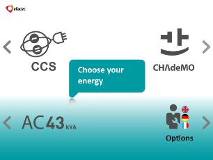
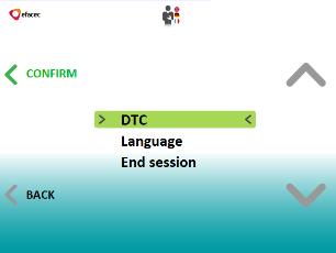

26 7.2.1 OPTIONS INTERFACES Figure 40 - Options interfaces Staff-POD /32


27 7.2.2 CHADEMO CHARGING SYSTEM INTERFACES Figure 41 - CHAdeMO interfaces Staff-POD /32


28 7.2.3 COMBINED CHARGING SYSTEM (CCS) INTERFACES or Connect CCS Cable Figure 42 - CCS interfaces Staff-POD /32
29 7.2.4 AC43 CHARGING SYSTEM INTERFACES Figure 43 - AC43 interfaces Staff-POD /32
30 7.2.5 AC22 CHARGING SYSTEM INTERFACES Figure 44 - AC22 interfaces Staff-POD /32
31 8 MAINTENANCE MANUAL ALL SERVICING MUST BE PERFORMED ONLY BY QUALIFIED PERSONNEL. DO NOT ATTEMPT TO SERVICE THE EFAPOWER EV QC45 QUICK CHARGING STATION YOURSELF. BY OPENING THE DOOR OR REMOVING THE EFAPOWER EV QC45 QUICK CHARGING STATION SIDE PANELS YOU RUN THE RISK OF EXPOSURE TO DANGEROUS VOLTAGES! IN CASE OF ANY KIND OF DOUBT REGARDING THIS CONTACT: Electronic Power Systems Unit Rua Eng.º Frederico Ulrich - Apartado MOREIRA MAIA - PORTUGAL Tel: (+351) Fax: (+351) apv-sa@efacec.com Electronic Power Systems Unit 2725 Northwoods Parkway, Ste. B Norcross, Georgia USA Tel: (1) Fax: (1) support.eem.usa@efacec.com EFACEC WILL ASSUME NEITHER RESPONSIBILITY NOR LIABILITY DUE TO INCORRECT OPERATION OR MANIPULATION OF THE EFAPOWER EV QC45 QUICK CHARGING STATION. EFACEC HAS TAKEN EVERY PRECAUTION TO PRODUCE AN ACCURATE, COMPLETE AND EASY TO UNDERSTAND MANUAL AND WILL THEREFORE ASSUME NO RESPONSIBILITY NOR LIABILITY FOR DIRECT, INDIRECT OR ACCIDENTAL PERSONAL OR MATERIAL DAMAGE DUE TO ANY MISINTERPRETATION OR UNDESIRED MISTAKES IN THIS MANUAL. THIS MANUAL MAY NOT BE COPIED NOR REPRODUCED PRIOR TO WRITTEN PERMISSION OF EFACEC. BEFORE ANY MAINTENANCE, THE OPERATOR OR SERVICE TECHNICIAN MUST NOT TOUCH THE CAPACITORS TERMINALS UNTIL THEY ARE DISCHARGED AND REACH THE SAFETY VALUE OF 50V (D.C.). 8.1 POWER UP ERRORS The following errors / messages can occur when the Quick Charging Station powers up. Table 3 - EFAPOWER EV-QC45 Power Up Errors Fault Possible Cause Action The display does not start Earth Leakage Fault The charger does not start charging Circuit breakers Q3 and/or Q7 are OFF Unit A6 (auxiliary power supply) failure Display failure Current higher than expected The card is not accepted Emergency Stop Button pressed Switch circuit breakers Q3 and/or Q7 ON Check and replace unit A6 if necessary Check and replace unit if necessary Disconnect and reconnect power (by turning the power to the charging station off then back on again. If the message continues to be displayed, call Efacec Customer Support. Use a valid and authorized card Turn the Emergency Stop Button to allow the charge Staff-POD /32
32 8.2 PREVENTIVE MAINTENANCE ALL SERVICING MUST BE PERFORMED ONLY BY QUALIFIED PERSONNEL. DO NOT ATTEMPT TO SERVICE THE EFAPOWER EV QC45 QUICK CHARGER STATION YOURSELF. BY OPENING THE DOOR OR REMOVING THE EFAPOWER EV QC45 QUICK CHARGING STATION SIDE PANELS YOU RUN THE RISK OF EXPOSURE TO DANGEROUS VOLTAGES! We advise compliance with the specified maintenance plans which provide cleaning procedures for the terminals, microswitches, capacitors, interface buttons and ventilation filters. Cleaning should be performed every 12 (twelve) months and more often if in harsh environmental conditions such as excessive snow or dust accumulation. Table 4 - EFAPOWER EV-QC45 Preventive Maintenance Operation Periodicity Estimated time(min) Tools Visual checking of the installation Each 12 months 15 Cleaning dust Each 12 months 30 AC input cables: Check the tightening torque of the cable connections. Each 12 months 15 Standard Tools Torque wrench Output cables: check if the connectors, cables and its connections are in perfect condition. Each 12 months 15 Standard Tools Torque wrench Check if microswitches from the circuit breakers, fuses are working correctly. Check the correct work of the cabinet fans, actuating the thermostat E2 Check the correct work of the Heater (if exists), actuating the thermostat E4 and the Hygrostat E3 Each 12 months 15 Multimeter Each 12 months 2 Standard tools Each 12 months 5 Standard tools Check the Emergency Stop Button correct work Each 12 months 1 Clean/Replace the fan filters Each 12 months 15 Panels cleaning with fresh water and a detergent, then rinsed with fresh water Each 12 months CHARGER / VEHICLE PROBLEMS ALL SERVICING MUST BE PERFORMED ONLY BY QUALIFIED PERSONNEL. DO NOT ATTEMPT TO SERVICE THE EFAPOWER EV QC45 QUICK CHARGER STATION YOURSELF. BY OPENING THE DOOR OR REMOVING THE EFAPOWER EV QC45 QUICK CHARGING STATION SIDE PANELS YOU RUN THE RISK OF EXPOSURE TO DANGEROUS VOLTAGES! Staff-POD /32
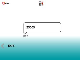
33 The following errors / messages can occur when attempting to charge a vehicle. In case of a Quick Charger Station problem, you should receive the message Charger Problem otherwise should appear Charger/Vehicle Problem. In this case you should return the charging connector to its holder and call Efacec Customer Support at: Electronic Power Systems Unit Rua Eng.º Frederico Ulrich - Apartado MOREIRA MAIA - PORTUGAL Tel: (+351) Fax: (+351) apv-sa@efacec.com Electronic Power Systems Unit 2725 Northwoods Parkway, Ste. B Norcross, Georgia USA Tel: (1) Fax: (1) support.eem.usa@efacec.com These errors/messages are identified by a code, which is needed to be decoded. To do so, user must follow the procedure represented in Figure 40 into chapter Options Interfaces DTC No. Possible cause Table 5 - EFAPOWER EV-QC45 General 1000 Main controller board reset The charger was powered up Charger problems Table 6 - EFAPOWER EV-QC45 Charger Problems DTC No. Message on Display / Indication for user Possible cause Charger problem Short circuit in output Charger problem Ground fault Charger problem Over voltage in output 10004/ Charger problem Over current in output Charger problem Heatsink overheat Charger problem Connector lock status maintenance Charger problem Connector unlocked Charger problem HMI charger communication problem Charger problem Power controller communication problem Charger problem Low mains voltage Charger problem Tilt fault activated Charger problem Input contactor failed or door opened Charger problem mains breaker opened Charger problem Fuses blown Charger problem Auxiliaries breaker opened Charger problem Inrush current contactor problem Charger problem No communication between controller and HMI 30xxx Charger problem High voltage in the output Staff-POD /32
34 Charger/Vehicle problems Table 7 - EFAPOWER EV-QC45 Charger/Vehicle Problems DTC No. Message on Display / Indication for user Possible cause Charger/Vehicle problem Car contactors closed before they should Charger/Vehicle problem Car contactors insulation failure Charger/Vehicle problem Battery not sensed Charger/Vehicle problem Car requested a higher current than charger can supply Charger/Vehicle problem CAN communications timeout Charger/Vehicle problem Car didn't sent a Current request Charger/Vehicle problem Car detected an overvoltage in the battery Charger/Vehicle problem Car detected an under voltage in the battery Charger/Vehicle problem Car detected a difference in its current measure and the measure provided by charger Charger/Vehicle problem Car detected an high battery temperature Charger/Vehicle problem ecar detected a difference in its voltage measure and the measure provided by charger Charger/Vehicle problem Someone force removed the connector Charger/Vehicle problem Vehicle made an emergency stop Staff-POD /32
35 [This Page Intentionally Left Blank] Staff-POD /32
36 Electronic Power Systems Unit Rua Eng.º Frederico Ulrich - Apartado MOREIRA MAIA - PORTUGAL Tel: (+351) Fax: (+351) apv-sa@efacec.com Staff-POD Electronic Power Systems Unit 2725 Northwoods Parkway, Ste. B Norcross, Georgia USA Tel: (1) Fax: (1) support.eem.usa@efacec.com EFAPOWER EV-QC45 STANDALONE - INSTALLATION AND USER MANUAL V 05.00
Installation Manual. Rev
 Installation Manual ChargePro 620 Charging Station is a trademark of SemaConnect, Inc. All other products or services mentioned are the trademarks, service marks, registered trademarks or registered service
INSTRUCTION & INSTALLATION
 INSTRUCTION & INSTALLATION MANUAL MODELS: CCL-eHOME T1C16 CCL-eHOME T1C32 CCL-eHOME T2C16 CCL-eHOME T2C32 WALLBOX ehome SERIES WALLBOX ehome Instruction and Installation manual This document is copyrighted,
Post evolve Series. Installation Manual
 Post evolve Series Installation Manual Post evolve Series Installation Manual COPYRIGHT INFORMATION This document is copyrighted, 2017 by Circontrol, S.A. All rights are reserved. Circontrol, S.A. reserves
Post evolve Series. Installation Manual
 Post evolve Series Installation Manual Post evolve Smart Series Installation Manual COPYRIGHT INFORMATION This document is copyrighted, 2017 by Circontrol, S.A. All rights are reserved. Circontrol, S.A.
Electric Vehicle Charging Station
 EVoReel Electric Vehicle Charging Station INSTALLATION GUIDE AND USER MANUAL Model: Dual Output Pedestal Mount 30A EVoReel EVSE Model Numbers: With Basic EVSE: EV072-400-002A; With Intelligent ievse: EV072-410-002A;
Electric Vehicle Charging
 Electric Vehicle Charging Efacec Electric Mobility With extensive experience designing and manufacturing power electronic products, Efacec offers solutions and products for different segments of EV charging
Instruction Manual. Blink HQ Charger. Charge on. a CarCharging Company
 Instruction Manual Blink HQ Charger a CarCharging Company 2014 by Blink Network, LLC No part of the contents of this document may be reproduced or transmitted in any form or by any means without the express
GE Energy Industrial Solutions. EV Charging Station. Application Guide. imagination at work
 GE Energy Industrial Solutions EV Charging Station Application Guide imagination at work EV Charging Station Introduction The GE EV Charging Station offers Level II charging capable of reducing charge
INSTALLATION GUIDE AND USER MANUAL
 Electric Vehicle Charging Station INSTALLATION GUIDE AND USER MANUAL SAE J1772 AC Level 2 EVSE Model: 30A EVoCharge EVSE Wall Mount P/N: EV072-300-001A Version 2.0 IMPORTANT Read this manual thoroughly
INSTALLATION GUIDE AND USER MANUAL
 Electric Vehicle Charging Station INSTALLATION GUIDE AND USER MANUAL Model: 30A EVoCharge EVSE Model Number: EV072-300-001A Product Safety Certification: UL and cul Listed Description: SAE J1772 AC Level
Electric Mobility. March 2014
 Electric Mobility March 2014 Efacec Electric Mobility o o o o EV Charging Solutions Quick Chargers Public Chargers Home Chargers Master Slave architectures Resume Table References Worldwide Total Installed
Mobility & emobility
 Mobility & emobility History Company founded in 1997. Circontrol believes that innovation, internationalization, quality, and close contact with the clients is the most effective way to offer the best
Express 100 DC Commercial Charging Stations
 Express 100 DC Commercial Charging Stations Specifications and Ordering Information Ordering Information Specify model number followed by the applicable code(s). The order code sequence is: Model-Options.
ChargePro 620 Electric Vehicle Charging Station Installation Guide
 ChargePro 620 Electric Vehicle Charging Station Installation Guide Wall Mount Pole Mount Contents Page 1 Page 2 Page 3 Page 4 Page 5 Page 6 Cover Sheet Safety and Compliance Pedestal Mount Installation
Matrix APAX. 380V-415V 50Hz TECHNICAL REFERENCE MANUAL
 Matrix APAX 380V-415V 50Hz TECHNICAL REFERENCE MANUAL WARNING High Voltage! Only a qualified electrician can carry out the electrical installation of this filter. Quick Reference ❶ Performance Data Pages
M T E C o r p o r a t i o n MATRIX FILTER. SERIES B Volts, 50HZ USER MANUAL PART NO. INSTR REL MTE Corporation
 M T E C o r p o r a t i o n MATRIX FILTER SERIES B 380-415 Volts, 50HZ USER MANUAL PART NO. INSTR - 015 REL. 060628 2006 MTE Corporation IMPORTANT USER INFORMATION NOTICE The MTE Corporation Matrix Filter
FLO Home TM G5 Model. Installation guide
 FLO Home TM G5 Model Installation guide Table of Contents Safety Instructions 3 Planning your Installation 4 Box Contents 5 Installing the Station 6 Setting the Current Limit 9 Light Indicator 11 Compliance
Installation Manual & Warranty
 Installation Manual & Warranty MuD Public Workplace Table of Contents What's Included... 2 Before Installation... 3 Safety Check... 4 Grounding Instructions... 4 Recommended Tools... 4 Installing the eluminocity
DC TO AC POWER INVERTER PWRIC150012W INSTRUCTION MANUAL
 DC TO AC POWER INVERTER PWRIC150012W INSTRUCTION MANUAL SAVE THIS MANUAL You will need the manual for the safety warnings and precautions, assembly instructions, operating and maintenance procedures, parts
M T E C o r p o r a t i o n MATRIX FILTER. SERIES B Volts, 50HZ USER MANUAL PART NO. INSTR REL MTE Corporation
 M T E C o r p o r a t i o n MATRIX FILTER SERIES B 380-415 Volts, 50HZ USER MANUAL PART NO. INSTR - 015 REL. 040709 2003 MTE Corporation IMPORTANT USER INFORMATION NOTICE The MTE Corporation Matrix Filter
EVlink Parking EVF1 - EVW1
 EVlink Parking EVF1 - EVW1 Parking Charging Stations User Manual 07/2013 EVF1ppppppp EVW1ppppppp DOCA0063EN-01 www.schneider-electric.com This document contains general descriptions and/or general technical
The Ultimate Smart Grid Solution INSTRUCTION MANUAL
 ECOWISE EW30/1 The Ultimate Smart Grid Solution INSTRUCTION MANUAL Welcome! Congratulations on selecting the ECOWISE unit to manage your energy supply needs. ECOWISE units reduce the amount of electric
DC TO AC POWER INVERTER PWRINV150W INSTRUCTION MANUAL
 DC TO AC POWER INVERTER PWRINV150W INSTRUCTION MANUAL SAVE THIS MANUAL You will need the manual for the safety warnings and precautions, assembly instructions, operating and maintenance procedures, parts
REFERENCE MANUAL FORM: MX-TRM-E REL REV MTE
 Matrix APAX 380V-415V 50Hz TECHNICAL REFERENCE MANUAL FORM: MX-TRM-E REL. September 2014 REV. 002 2014 MTE Corporation WARNING High Voltage! Only a qualified electrician can carry out the electrical installation
Combiner Manual #OMBINER #OMBINER < 2* )NSTALLATION 7(&+12/ i 62/$5
NSTALLATION 7(&+12/ i 62/$5") Combiner Manual i ii Combiner Manual Combiner Manual Copyright 2004 SMA America, Inc. All rights reserved. All rights reserved. No part of this document may be reproduced, stored in a retrieval system,
Combiner Manual i ii Combiner Manual Combiner Manual Copyright 2004 SMA America, Inc. All rights reserved. All rights reserved. No part of this document may be reproduced, stored in a retrieval system,
Nature Power Inverters. True Sinewave Inverter Modified Sinewave Inverter. Owner s Manual
 Version 1.1 Version 2 Nature Power Inverters True Sinewave Inverter Modified Sinewave Inverter Owner s Manual!!!!!!!!!!! 38304 38204 For safe and optimum performance, the Power Inverter must be used properly.
Electric Vehicle Charging Solutions Powering the Future of Sustainable Mobility
 Electric Vehicle Charging Solutions Powering the Future of Sustainable Mobility Catalog 2800CT1001R04/12 2012 Class 2800 CONTENTS Description............................................ Page 2 Indoor Charging
T Series (N6052T) Solar Battery Hybrid System. Installation Manual Version 1.1
 Solar Battery Hybrid System. Installation Manual Version 1.1") T Series (N6052T) Solar Battery Hybrid System Installation Manual Version 1.1 Content 1. Safety... 1 1.1 How to Use This Manual... 1 1.2 Safety Rules... 1 1.3 Warning Notices Affixed to the Device... 2
T Series (N6052T) Solar Battery Hybrid System Installation Manual Version 1.1 Content 1. Safety... 1 1.1 How to Use This Manual... 1 1.2 Safety Rules... 1 1.3 Warning Notices Affixed to the Device... 2
Appendix: Safety and application notes for... 15
 Contents Safety... 2 Warnings... 2 Symbols used in this manual... 2 Operator s safety... 2 Avoid filter module damage... 2 DC-link resonance... 2 Description... 3 Description... 3 Ordering numbers, 380-415
RE-PR1-F 1-Phase Din-Rail Mount 1.5, 3 & 6kW
 Page 1 of 5 RE-PR1-F 1-Phase Din-Rail Mount 1.5, 3 & Features: Benefits: 0-10Vdc or 0-5Vdc control input Over temperature protection with auto reset Din-rail mounting Efficient electronic switching No
BMW i. Freude am Fahren. Wallbox PURE. Installation instruction
 BMW i Freude am Fahren Wallbox PURE Installation instruction Imprint Bestellnummer 61 90 2 347 662 Wallbox Pure Type T2 (32 A, 7.4 kw) Publisher Bayerische Motorenwerke Aktiengesellschaft Munich, Germany
Sunny Boy Accessories SUNNY BOY COMBINER BOX TLUS SBCBTL6
 Sunny Boy Accessories SUNNY BOY COMBINER BOX TLUS SBCBTL6 Installation Guide SBCBTLUS-IUS094510 IMUS-SBCBTLUS Version 1.0 US SMA America, LLC Legal Restrictions Copyright 2010 SMA America, LLC. All rights
WattStation Wall Mount User Manual
 GE Energy WattStation Wall Mount User Manual imagination at work Table of Contents 1. Grounding Instructions...3 1.1 Safety and Compliance...3 1.2 Grounding Instructions...3 2. Installation Instructions...3
FLO Home TM X5 Model. Installation Manual FLO Services Inc. All rights reserved.
 FLO Home TM X5 Model Installation Manual 2016 FLO Services Inc. All rights reserved. v161130:2013 Table of Contents Specifications 3 Safety Instructions 4 Planning your Installation 5 Box Contents 6 Installing
Model HPX60 Series Automatic Battery Charger User s Manual Rev. 1.0 October 17, 2006
 B R A N D Model HPX60 Series Automatic Battery Charger User s Manual Rev. 1.0 October 17, 2006 For Sales, Support and Service phone: 407-331-4793 fax: 407-331-4708 website: www.xenotronix.com email: information@xenotronix.com
LV Capacitor CLMD03 Power Module Instruction manual
 LV Capacitor CLMD03 Power Module Instruction manual Table of Contents 1 Safety... 3 2 Upon reception... 3 2.1 Inspection on reception... 3 2.2 Storage- transportation handling... 3 3 Hardware Description...
Model LA 4100 Time Delay OFF Controller
 ISIMET LA Series Model LA 4100 Time Delay OFF Controller Installation, Operation and Maintenance Manual Application: The Time Delay OFF Controller operates as a single output controller where the application
GEatom306KHF-5U Three-phase Grid-Tied Battery Inverter. Version 1.1. Global Mainstream Dynamic Energy Technology Ltd. 1
 GEatom306KHF-5U Three-phase Grid-Tied Battery Inverter Version 1.1 Global Mainstream Dynamic Energy Technology Ltd. 1 Content Prelude... 4 1. Safety... 5 1.1 How to Use This Manual... 5 1.2 Safety Rules...
The Ultimate Smart Grid Solution INSTRUCTION MANUAL
 ECOWISE EW20/1 EW30/1 The Ultimate Smart Grid Solution INSTRUCTION MANUAL Welcome! Congratulations on selecting the ECOWISE unit to manage your energy supply needs. ECOWISE units reduce the amount of electric
RVS-AX Instruction Manual
 RVS-AX Analog Soft Starter 8-170A, 220-600V Instruction Manual Ver. 10/11/2009 2 Table of Content RVS-AX Instruction Manual 1. TABLE OF CONTENT 1. Table of Content...2 2. Safety & Warnings...3 2.1 Safety...3
SBCB-6, SCCB-12, 28, 52 6 to 52 Circuit Combiner Boxes
 Combiner Manual SBCB-6, SCCB-12, 28, 52 6 to 52 Circuit Combiner Boxes User Manual U.S. Version 2.4 DOC-CBUG-01 i ii Combiner Manual Combiner Manual Copyright 2012 SMA America, LLC. All rights reserved.
ATS22D88Q soft starter-ats22-control 220V-power 230V (22kW)/ V(45kW)
/ V(45kW)") Product datasheet Characteristics ATS22D88Q soft starter-ats22-control 220V-power 230V (22kW)/400...440V(45kW) Complementary Assembly style Function available Supply voltage limits Main Range of product
Product datasheet Characteristics ATS22D88Q soft starter-ats22-control 220V-power 230V (22kW)/400...440V(45kW) Complementary Assembly style Function available Supply voltage limits Main Range of product
Smart equipment and Systems for electric vehicle charging
 Smart equipment and Systems for electric vehicle charging Technology for energy efficiency 1 The electric vehicle, the smartest option for a sustainable future The emergence of Electric Vehicles (EV) has
VADA - V60-J PRODUCT OVERVIEW CONSTRUCTION MOTOR USAGE LIMITATIONS WARRANTY
 PRODUCT OVERVIEW The VADA series of self priming jet pumps combine the functional benefits of centrifugal pumps and the practical and qualitative benefits of self-priming pumps. The Venturi system the
User s Manual. ClipperCreek, Inc. Innovative Infrastructure for Electric and Hybrid Vehicles. Model PCS-15
 ClipperCreek, Inc. Innovative Infrastructure for Electric and Hybrid Vehicles User s Manual ClipperCreek, Inc. 11850 Kemper Rd., Suite E Auburn, CA 95603 www.clippercreek.net Model PCS-15 THIS PAGE INTENTIONALLY
Power Inverter 400 MW Owner s Manual
 Power Inverter 400 MW 1204 Owner s Manual For safe and optimum performance, the Power Inverter must be used properly. Carefully read and follow all instructions and guidelines in this manual and give special
INSTRUCTIONS FOR THE RELIANCE Fast/Tran TM ARL0909 & ARL0909R
 INSTRUCTIONS FOR THE RELIANCE Fast/Tran TM ARL0909 & ARL0909R THE RELIANCE Fast/Tran IS NOT FOR "DO-IT-YOURSELF" INSTALLATION. It must be installed by a qualified electrician thoroughly familiar with all
Thyristor power controller TE10A. Burst-firing Single-cycle Advanced Single-cycle
 Thyristor power controller TE10A Burst-firing Single-cycle Advanced Single-cycle Control of short-wave infrared elements and loads of constant resistance up to 20kW User Manual Copyright Eurotherm Automation
General Installation Manual 2007 Sanyo Electric Co., Ltd. All Rights Reserved 6/15/07
 General Installation Manual for SANYO HIT Photovoltaic Modules. Please read this manual completely before use or installation of SANYO modules. This manual applies to the following models: HIP-205BA3,
Power consumption In operation At rest For wire sizing. Torque Inhibiting torque. 150 s / C Sound power level Motor
 Technical data sheet GK24G- SuperCap rotary actuator with emergency setting function and extended functionalities in the IP66 protective housing for adjusting air dampers in ventilation and air-conditioning
ACC Series Power Conditioner OPERATION & INSTALLATION MANUAL
 ACC Series Power Conditioner OPERATION & INSTALLATION MANUAL PHASETEC digital power conditioners are designed to safely operate electrical equipment in the harshest power quality environments. With a wide
Switching DC Power Supply
 99 Washington Street Melrose, MA 02176 Phone 781-665-1400 Toll Free 1-800-517-8431 Visit us at www.testequipmentdepot.com Model 1693, 1694 Switching DC Power Supply INSTRUCTION MANUAL 1 Safety Summary
INSTALLATION USER MANUAL
 INSTALLATION & USER MANUAL DYNAMIC LOAD MANAGEMENT -PREMIUM- This document is copyrighted, 2016 by Circontrol, S.A. All rights are reserved. Circontrol, S.A. reserves the right to make improvements to
Model LA 4300 Time Delay OFF Controller
 ISIMET LA Series Model LA 4300 Time Delay OFF Controller Installation, Operation and Maintenance Manual Application: The Time Delay OFF Controller operates as a single output controller where the application
Battery Charger Retrofit Kit Q-DCCHG1 for DC Cabinet Retrofit Manual
 Battery Charger Retrofit Kit Q-DCCHG1 for DC Cabinet Retrofit Manual 25500181 Rev. A0 415 Printed in U.S.A. Copyright 2015 Federal Signal Corporation Limited Warranty The Alerting and Notification Systems
Battery Chargers Sealed or Valve Regulated Lead Acid Batteries Model: PSC AP
 Battery Chargers Sealed or Valve Regulated Lead Acid Batteries Model: PSC-124000AP OPERATING PROCEDURES AND SAFETY INSTRUCTIONS CAUTION: TO PREVENT THE RISK OF ELECTRIC SHOCK, DO NOT REMOVE COVER NO USER
S150,S300 Series Pure Sine Wave Inverter User s Manual
 S150,S300 Series Pure Sine Wave Inverter User s Manual List of contents 1. Important Safety Instructions 3 1-1 General Safety Precautions 3 1-2 Precautions When Working With Batteries.. 3 2. Features...
Model LA 4400 Time Delay OFF Controller
 ISIMET LA Series Model LA 4400 Time Delay OFF Controller Installation, Operation and Maintenance Manual Application: The Time Delay OFF Controller with integral 24-hr. programmable time clock operates
TO AVOID DOING IRREPARABLE DAMAGE TO DRIVE CIRCUITRY NEVER APPLY AC POWER DIRECTLY TO LED LIGHTBOXES!
 INSTALLATION MANUAL TO AVOID DOING IRREPARABLE DAMAGE TO DRIVE CIRCUITRY NEVER APPLY AC POWER DIRECTLY TO LED LIGHTBOXES! 4949 South 110 th Street Greenfield, WI 53228 Phone: (800) 610-6053 Fax: (414)
F-4600 INLINE ULTRASONIC FLOW METER Installation and Operation Guide
 F-4600 INLINE ULTRASONIC FLOW METER Installation and Operation Guide 11451 Belcher Road South, Largo, FL 33773 USA Tel +1 (727) 447-6140 Fax +1 (727) 442-5699 1054-7 / 34405 www.onicon.com sales@onicon.com
Updated: October 2012
 T: (630) 794-5100 EMERGENCY POWER FUEL SYSTEMS Earthsafe Systems, Inc. 7320 S. Madison Willowbrook, IL 60527 F: (630) 794-5106 info@earthsafe.com www.earthsafe.com Updated: October 2012 The information
Electric Vehicle Charging Station Products Charge Cable Management Solutions
 30ft Cable Length Self-Retracts Electric Vehicle Charging Station Products Improved Safety EVoReel reduces trip hazards and likelihood of connector damage. The EVoReel brand promotes OSHA and ADA regulations
Installing Power Components
 This chapter provides instructions on how to install and reinstall power components in the Cisco NCS 4016 chassis. It also covers connecting and disconnecting power and powering on the chassis. The Cisco
KEWTECH. KT56 digital multi function tester. Instruction manual
 KEWTECH KT56 digital multi function tester Instruction manual Contents 1 Safety Notice 1 2 Features and Principles of Measurement 3 3 Introduction 6 4 Specifications 7 5 Instrument layout 9 6 Operating
USER GUIDE TURBOCORD TM PORTABLE CHARGER 240V. AeroVironment EV Solutions
 USER GUIDE TURBOCORD TM PORTABLE CHARGER 240V AeroVironment EV Solutions 2013 AeroVironment, Inc. All rights reserved. AeroVironment, EV Solutions, and the AeroVironment logo are trademarks of AeroVironment,
ClipperCreek, Inc. Innovative Infrastructure for Electric and Hybrid Vehicles. User s Manual. Model ACS
 ClipperCreek, Inc. Innovative Infrastructure for Electric and Hybrid Vehicles User s Manual Model ACS PLEASE NOTE This user s manual includes the latest information at the time of printing. ClipperCreek,
Instruction Manual. Harmonic Filter AHF 005/010. Drives Solutions
 Harmonic Filter AHF 005/010 Instruction Manual Drives Solutions Contents Safety... 2 Warnings... 2 Symbols used in this manual... 2 Operator s safety... 2 Avoid filter module damage... 2 DC-link resonance...
FLO Home TM X5 Model. Installation Guide
 FLO Home TM X5 Model Installation Guide Table of Contents Safety Instructions 3 Planning your Installation 4 Box Contents 5 Installing the Station 6 Installing the PLC 9 Checking the PLC connection 10
MST FULL HEIGHT TURNSTILES TYPICAL INSTALLATION SITES COMMON APPLICATIONS DESCRIPTIVE SPECIFICATIONS ALVARADOMFG.COM
 DESCRIPTIVE SPECIFICATIONS The is the most trusted, secure and reliable full height turnstile available. It is installed in thousands of locations around the world and offers key product features and benefits
& HIGH CURRENT DC POWER SUPPLIES INSTRUCTION MANUAL
 72-6850 & 72-6852 HIGH CURRENT DC POWER SUPPLIES INSTRUCTION MANUAL Table of Contents Introduction 2 Specification 2 Safety 4 EMC 5 Installation 6 Connections 6 Operation 7 Maintenance and Repair 8 www.tenma.com
Installation Guide. CT500 ChargePoint Networked Charging Station
 by Coulomb Technologies CT500 ChargePoint Networked Charging Station Installation Guide Coulomb Technologies Inc. 1692 Dell Ave. Campbell, CA 95008-6901 USA US toll free: +1-877-370-3802 www.coulombtech.com
Matrix AP 400V 690V INSTALLATION GUIDE. Quick Reference. ❶ How to Install Pages 6 20 ❷ Startup/Troubleshooting Pages WARNING
 Matrix AP 400V 690V INSTALLATION GUIDE FORM: MAP-IG-E REL. May 2017 REV. 002 2017 MTE Corporation WARNING High Voltage! Only a qualified electrician can carry out the electrical installation of this filter.
1329I Integrated Drive/Motor CE Filter Option Kit
 Instruction Sheet 1329I Integrated Drive/Motor CE Filter Option Kit CE filter options are designed to be used with the 1329I Integrated Drive/Motor. The main function of the CE filter is to reduce the
Enelion Vertica. Installation manual. 22 kw. for the specialists
 Enelion Vertica kw Installation manual for the specialists ver..6 Enelion 05.07 Enelion VERTICA General notes At various points in this manual you will see notes and precautionary warnings regarding possible
3 ft. Interconnect Standard (EVSE): EVO A
: EVO A") LINEITEM 1 30A EVoReel EVSE Wall/Ceiling Mount Interchangeable Wall/Ceiling Mount AC Connection Type: Standard EVSE: 1 ft. NEMA 6-50 Plug (removable for Hardwire Connection) Intelligent ievse: Hardwire
LINEITEM 1 30A EVoReel EVSE Wall/Ceiling Mount Interchangeable Wall/Ceiling Mount AC Connection Type: Standard EVSE: 1 ft. NEMA 6-50 Plug (removable for Hardwire Connection) Intelligent ievse: Hardwire
1. INTRODUCTION SYSTEM DESCRIPTION Front Panel CONNECTION AND OPERATION TROUBLESHOOTING...8
 Contents : 1. INTRODUCTION...1 2. IMPORTANT SAFETY INSTRUCTIONS...2 3. SYSTEM DESCRIPTION...4 3.1 Front Panel...4 4. CONNECTION AND OPERATION...6 5. TROUBLESHOOTING...8 6. MAINTENANCE...9 6.1 Operation...9
Galaxy VM. Battery Breaker Box Installation 09/
 Galaxy VM Battery Breaker Box Installation 09/2016 www.schneider-electric.com Legal Information The Schneider Electric brand and any registered trademarks of Schneider Electric Industries SAS referred
The Power of Reliability INSTRUCTION MANUAL
 The Power of Reliability INSTRUCTION MANUAL SAFETY & WARNINGS Read this manual carefully and understand all Warnings and Cautions before connections are made to the Inverter. If unsure about any aspects
PowerLogic High Density Metering System 4-Meter Enclosure Installation Guide
 PowerLogic High Density Metering System 4-Meter Enclosure Installation Guide 7002-0289-00 Instruction Bulletin HAZARD CATEGORIES AND SPECIAL SYMBOLS Read these instructions carefully and look at the equipment
Table of Contents 文管中心 發行章
 ST600-XXX Series Pure Sine Wave Power Inverter User s Manual Table of Contents 1. Important Safety Instructions 1-1 General Safety Precautions 1 1-2 Battery Precautions. 1 2. Basic Descriptions 2-1 Mechanical
Appendix: Safety and application notes for 19
 Contents Safety 2 Warnings 2 Symbols used in this manual 2 Operator's safety 2 Avoid filter module damage 2 DC-link resonance 2 Description 3 Description 3 Ordering numbers, 380-415 V, 50 Hz 4 Ordering
Wilo-Control SC-Fire Jockey
 Pioneering for You Wilo-Control SC-Fire Jockey de en fr Einbau- und Betriebsanleitung Installation and operating instructions Notice de montage et de mise en service nl Inbouw- en bedieningsvoorschriften
EVoInnovate EVSE Model Numbers: EVO & EVO User Manual & Installation Guide. Revision 1.0
 EVoInnovate EVSE Model Numbers: EVO32-300-001 & EVO32-300-002 User Manual & Installation Guide Revision 1.0 IMPORTANT SAFETY INSTRUCTIONS This document contains instructions and warnings that must be followed
Dimensions 12/800N 12/1200N D. DC to AC Power Inverters. OWNERS MANUAL for Models: OWNERS MANUAL April ISO 9001:2000 Certified Company
 Manufacturer of Dimensions Inverters 4467 White Bear Parkway St. Paul, MN 55110 Phone: 651-653-7000 Fax: 651-653-7600 E-mail: inverterinfo@sensata.com Web: www.dimensions.sensata.com OWNERS MANUAL April
1.1 Caution Statements
 USER MANUAL 1.1 Caution Statements Caution Statements cannot cover every potential cause of equipment damage but can highlight common causes of damage. It is the installer's responsibility to read and
Allen-Bradley Parts. CENTERLINE 2500 Motor Control Centers Installing, Joining and Splicing Columns. Installation Instructions. Catalog Number 2500
 Installation Instructions CENTERLINE 2500 Motor Control Centers Installing, Joining and Splicing Columns Catalog Number 2500 Topic Page Important User Information 2 Location Planning 3 Environment 3 Removal
MAKING MODERN LIVING POSSIBLE. UniLynx Indoor Installation Manual. ULX 1800i ULX 3000i ULX 3600i ULX 5400i SOLAR INVERTERS
 MAKING MODERN LIVING POSSIBLE UniLynx Indoor Installation Manual ULX 1800i ULX 3000i ULX 3600i ULX 5400i SOLAR INVERTERS Contents Contents 1. Introduction 2 Introduction 2 Installation Sequence 2 Important
Electric Vehicle Charging Safety Guidelines Part 2: Selection and Installation Edition DRAFT
 Date of publication: 1 November 2016Not yet published Issued by: Mark Wogan, Manager Energy Safety WorkSafe New ZealandNot yet issued Electric Vehicle Charging Safety Guidelines Part 2: Selection and Installation
User Manual Solar Charge Controller 3KW
 User Manual Solar Charge Controller 3KW Version: 1.3 CONTENTS 1 ABOUT THIS MANUAL... 1 1.1 Purpose... 1 1.2 Scope... 1 1.3 SAFETY INSTRUCTIONS... 1 2 INTRODUCTION... 2 2.1 Features... 2 2.2 Product Overview...
StarEye. 350 ma version. No control electronics on board
 StarEye 350 ma version No control electronics on board CONTENT 1 PICTURE... 3 1.1 GENERAL... 3 2 DIMENSIONS... 4 3 SAFETY INFORMATION... 5 3.1 SYMBOLS... 5 3.2 PROTECTION FROM ELECTRIC SHOCK... 6 3.3 PROTECTIONS
Cat. No. I526-E1-1 USER S MANUAL 3G3IV-PLKEB2 /4. Braking Resistor Units 3G3IV-PCDBR2 B/4 B. Braking Units
 Cat. No. I526-E1-1 USER S MANUAL 3G3IV-PLKEB2 /4 Braking Resistor Units 3G3IV-PCDBR2 B/4 B Braking Units Thank you for choosing an OMRON Braking Resistor Unit and Braking Unit. Proper use and handling
User Manual. Solar Charge Controller 3KW
 User Manual Solar Charge Controller 3KW 1 CONTENTS 1 ABOUT THIS MANUAL... 3 1.1 Purpose... 3 1.2 Scope... 3 1.3 SAFETY INSTRUCTIONS... 3 2 INTRODUCTION... 4 2.1 Features... 4 2.2 Product Overview... 5
INSTRUCTIONS FOR THE RELIANCE CONTROLS ARM SERIES AUTOMATIC TRANSFER SWITCH
 INSTRUCTIONS FOR THE RELIANCE CONTROLS ARM SERIES AUTOMATIC TRANSFER SWITCH THE RELIANCE CONTROLS ARM SERIES AUTOMATIC TRANSFER SWITCH IS NOT FOR "DO-IT-YOURSELF" INSTALLATION. It must be installed by
GP-1000 Inverter. Go Power! Electric Inc. PO Box 6033 Victoria, BC V8P 5L4 Tel: Fax:
 Go Power! Manual GP-1000 Inverter Go Power! Electric Inc. PO Box 6033 Victoria, BC V8P 5L4 Tel: 866-247-6527 Fax: 866-607-6527 Email: info@gpelectric.com Table of Contents 1. INTRODUCTION 3 2. SPECIFICATIONS
MST. Full Height Turnstiles. alvaradomfg.com
 Full Height Turnstiles alvaradomfg.com The is the most trusted, secure and reliable full height turnstile available. It is installed in thousands of locations around the world and offers key product features
This manual is to be given to the end user. Optional RFI filter. Drive. Stop. Thermal protection device. Start / Reset +DC.
 3943 en - 2013.12 / c Optional RFI filter This manual is to be given to the end user Main contactor power supply Start / Reset Stop Thermal protection device Drive +DC BR Braking resistor DIGIDRIVE SK
Technical Data Sheet. Uninterruptible Power Supply. Critical Power. imagination at work
 Technical Data Sheet Uninterruptible Power Supply SGSE_010-040_S1_UPS_GE_01 GE Consumer & Industrial SA General Electric Company CH 6595 Riazzino (Locarno) Switzerland T +41 (0)91 / 850 51 51 F +41 (0)91
Model 8144NC Fresh Air Ventilator
 Model 8144NC Fresh Air Ventilator Installation and Operating Instructions MOUNTING BRACKETS WIRE ENTRY LOCATION INTEGRAL PRESSURE PORTS (PORT ON INLET SIDE NOT SHOWN) OVAL OUTLET COLLAR FOR 6" DIAMETER
Electric Vehicle Supply Equipment EVSE Vehicle Simulator
 Electric Vehicle Supply Equipment EVSE Vehicle Simulator Equipment design and Operating Instructions GS1007 A Technicians Service Tool to enable the functional, safety and operation of an installed EVSE
BK BK A BK MA BK MA BK J93 MN93-BK MN193-BK MR193-BK SL261-BK SR193-BK
 n COMPATIBLE CURRENT PROBES & SENSORS FOR POWER QUALITY METERS 193-24-BK 193-36-BK A196-24-BK MA193-10-BK MA193-14-BK J93 MN93-BK MN193-BK MR193-BK SL261-BK SR193-BK E N G L I S H User Manual Copyright