SENS DC PowerCab 120 Installation, Operation, & Maintenance Manual
|
|
|
- Willa Shepherd
- 5 years ago
- Views:
Transcription

1 Installation, Operation, & Maintenance Manual
2 Stored Energy Systems Packaged By: 1840 Industrial Circle C&C Power, Inc. Longmont, Co Mission Street Carol Stream, IL Technical Support: Phone: (303) or (800) SENS, the SENS logo and PowerCab are trademarks of Stored Energy Systems LLC. 8/24/ R04
3 TABLE OF CONTENTS 1. Important Information About This Manual Manual Symbols Introduction Safety Precautions Inspection Upon Receipt of Goods General Visible Damage Concealed Damage Return of Damaged Goods System Overview System Specifications Batteries System Grounding AC Input DC Output Optional AC Output Optional LVD General Specifications Installation Preparation Equipment Inspection Necessary Equipment and Tools Installation Safety Precautions Installation Steps Equipment Location Equipment Mounting Equipment Grounding AC/DC Connections System Operation System Maintenance Battery Replacement Reference Materials Warranty /24/ R04
4 1. IMPORTANT INFORMATION ABOUT THIS MANUAL SAVE THESE INSTRUCTIONS! This manual contains important information that is needed during the installation and maintenance of the system. 1.1 MANUAL SYMBOLS Warning / Caution: Indicates information provided to protect the user against personal injury, safety hazards and/or possible equipment damage. Important: Indicates information provided as an installation or operating instruction or tip as well as general important installation and system information. 8/24/ R04
5 2. INTRODUCTION Stored Energy Systems (SENS ) would like to thank you for choosing SENS product for your power and back-up equipment needs. We know there are a lot of choices in the industry, and we appreciate the opportunity to supply our customers with the highest quality power products manufactured in the United States. All SENS products are built to the highest industry standards and are Hi Pot tested to UL standards prior to shipment. All standard configurations are C-UL listed. Sales support for existing or future equipment needs are provided by our technical sales staff. For all technical, sales, and service related questions please call our office line at and you will be directed to the appropriate individual to answer your questions. After normal working hours please leave a detailed message, with your phone number, on our voice mail system and a qualified representative will contact you as quickly as possible. Stored Energy Systems Packaged By: 1840 Industrial Circle C&C Power, Inc. Longmont, Co Mission Street Carol Stream, IL Technical and Sales Support: Phone: (303) or (800) service@sens-usa.com 8/24/ R04
6 3. SAFETY PRECAUTIONS Before installing or maintaining this system, it is extremely important to read this manual and be sure that all system drawings and schematics are reviewed and clearly understood. If there are any questions concerning this manual or any of the installation or maintenance procedures and/or requirements please contact a C&C Power representative before proceeding. When installing this power system, follow all applicable federal, state and local regulations as well as industry guidelines to insure proper system installation. Only qualified electricians or DC power technicians should attempt to install or service this equipment. System installation and maintenance should always be performed with heavily insulated tools. It is also recommended to wear rubber gloves, boots, and use insulating mats to stand on when working on this equipment. Always wear eye protection when installing or maintaining batteries and/or power equipment. Do not attempt to unpack or move the battery cabinet without assistance. Use appropriate handling equipment rated to bear the weight and bulk of the battery cabinet, such as freight elevators, pallet jacks and forklifts. (Fully extend forks under load. Spread forks to maximum possible width under load. Lift cabinet from bottom only. Wear safety shoes.) Do not smoke or present open flames near any battery system. For the safety of others, never leave an open cabinet or panel unattended. To reduce the risk of fire, replace fuses with the same type and rating of fuses supplied with the system. 8/24/ R04
7 DC Power and Batteries can be very dangerous and have extremely high short circuit current. Electrical shock, severe burns, fire or death can result from a system short. To avoid personal injury including electrical shock, severe burns and possible death, all jewelry including bracelets, rings and watches must be removed prior to installing or servicing this system. Do not open or mutilate batteries. Opened or severely damaged batteries can release toxic electrolyte which is harmful to the skin and eyes. Never lay loose cables, metal parts or tools on top of batteries. Under certain conditions, batteries can vent potentially explosive gas (hydrogen). Never enclose batteries or battery cabinets in a sealed room. 8/24/ R04
8 4. INSPECTION UPON RECEIPT OF GOODS 4.1 GENERAL Special precautions and care have been taken to ensure the system arrives safe and undamaged. However, upon receipt, you should inspect the entire shipment, including the crate and any boxes for evidence of damage that may have occurred during transit. 4.2 VISIBLE DAMAGE It is the responsibility of the person receiving the shipment to inventory and fully inspect all materials against the bill of lading or weigh bill IMMEDIATELY while the carrier representative is still present. Insure that all items are accounted for, including number of skids and quantity of boxes. Also note any visible external damage that may have occurred during transit. Make all applicable notations on the delivery receipt before signing and file a damage report with the carrier. 4.3 CONCEALED DAMAGE Within 3 to 30 days of receipt (depending on courier), unpack the system and check for any concealed damage. Check the materials received against the detailed packing list to verify the quantity and the condition as complete and satisfactory. Note any damage to the internal packaging, then request an inspection by the carrier and file a concealed damage claim. If there is a material shortage, contact a representative at SENS to file a claim. Please contact your shipping company for all shipping damage. C&C Power is not responsible for any shipping damage. 4.4 RETURN OF DAMAGED GOODS Should equipment be damaged and require return, contact SENS Technical Support. A representative will provide instructions along with an RMA number to expedite the return. A RMA number must be obtained before returning equipment to Sens or C&C Power, Inc. 8/24/ R04
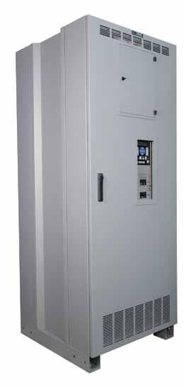
9 5. SYSTEM OVERVIEW The DC PowerCab 120 is a non-stop DC power system designed to deliver uninterruptible DC power to critical loads. PowerCab includes a DC power supply/charger, storage battery string, and DC distribution to load center. In addition to the charger, battery, distribution panel and cabinet, PowerCab can be optionally equipped with: Additional DC distribution Low voltage disconnect (to prevent battery from over-discharge) Top-Lift Bracket Multiple DC to AC inverter options The DC PowerCab system is fully factory assembled and is ready to install upon delivery. 8/24/ R04
10 6. SYSTEM SPECIFICATIONS 6.1 BATTERIES Type: Valve Regulated Lead Acid (VRLA), sealed, non-spillable Amp-Hour Options: 100 AH, 150AH, 170AH or 200AH Voltage: 12 VDC Nominal Only cabinets with Flame Retardant Batteries are suitable for computer room use. 6.2 SYSTEM GROUNDING All system ground wires should be derived from the main building ground source. Cabinet Safety Ground: Each cabinet is supplied with a mechanical ground lug that accepts bare wire from #2/0 AWG to #14 AWG. Torque: 375 in-lbs Wire Size and Type: Ground wire should be sized per NEC and/or all applicable national and local codes. 6.3 AC INPUT The AC input to the charger (see Figure 1 for location) can be: 208 VAC 60 Hz, 1ф 230 VAC 50/60 Hz, 1ф 240 VAC 60 Hz, 1ф /208/ VAC 60 Hz, 1ф /208/ VAC, 50/60 Hz, 1ф 400 VAC 50/60 Hz, 1ф 480 VAC 60 Hz, 1ф 6.4 DC OUTPUT DC Output Voltage Options include: 24-volt nominal (12 cells lead-acid) 48-volt nominal (24 cells lead-acid) 120-volt nominal (60 cells lead-acid) 240-volt nominal (120 cells lead-acid) Charger Output Current Options include: 6 Amps (15A charger to panelboard breaker) 12 Amps (15A charger to panelboard breaker) 16 Amps (20A charger to panelboard breaker) 25 Amps (35A charger to panelboard breaker) 35 Amps (45A charger to panelboard breaker) 50 Amps (70A charger to panelboard breaker) 8/24/ R04
11 75 Amps (100A charger to panelboard breaker) 100 Amps (125A charger to accessory breaker) 150 Amps (200A charger to accessory breaker) DC Load Center: Panelboard, 100A, 2-pole battery main breaker, 2-pole charger-feed breaker, plus 12 each 2-pole load breaker positions. Wire Size and Type: Per NEC and/or all applicable national and local codes. 6.5 OPTIONAL AC OUTPUT 600 Watt Inverter, 120VAC, 60Hz 600 Watt Inverter, 230VAC, 50Hz 1000 Watt Inverter, 120VAC, 60Hz 1000 Watt Inverter, 230VAC, 50Hz 1100 Watt Inverter, 120VAC, 60Hz 1100 Watt Inverter, 230VAC, 50Hz 2000 Watt Inverter, 120VAC, 60Hz 2000 Watt Inverter, 230VAC, 50Hz 3000 Watt Inverter, 120VAC, 60Hz 3000 Watt Inverter, 230VAC, 50Hz AC output option consumes one 2-pole load breaker position. Wire Size and Type: Per NEC and/or all applicable national and local codes. Wire should be sized for a maximum voltage drop of 0.5 volt. 6.6 OPTIONAL LVD When AC power fails, the systems batteries will discharge in order to provide the necessary backup power to the load. If the DC PowerCab 120 is equipped with the Low Voltage Disconnect (LVD) feature, the system load will be automatically disconnected at the customer adjustable LVD disconnect voltage setting. This will prevent the batteries from being discharged to unsafe levels. A Bender VME420 type Digital Voltage Monitor Relay is used to control the contactor in the LVD circuit. The LVD circuit, with the Monitor Relay imbedded, wiring connections to the DC load center and the Charger is shown in Figure 2/Section 9. The activation and factory settings of the LVD Voltage Relay are shown in Figure 3/Section 9 for a 120 VDC system, Figure 4/Section 9 for a 48 VDC system and Figure 5/Section 9 for a 24 VDC system. 6.7 GENERAL SPECIFICATIONS Cabinet Size: 30.5 W x 31.5 D x 78.7 H Typical Weights: Empty Cabinet (approximately): 450 lbs Complete System Weight can be found on the individual cabinet drawing that is mounted to the inside of the door. 8/24/ R04
12 Operating Temperature: 20 C to 25 C (68 F to 77 F) recommended for optimum battery performance. Ventilation: Ventilation holes located in the front, rear, and top of the cabinet. Clearance around the equipment should be as suggested by NEC and/or all applicable national and local codes. The battery cabinet does not require rear access or rear clearance. Under certain conditions, batteries can vent potentially explosive gas (hydrogen). Never enclose batteries or battery cabinets in a sealed room. Batteries should be stored no longer than three months at 25 C (77 F) or lower before recharging. Exceeding the recommended ambient storage temperature may cause damage to the batteries. 8/24/ R04
13 7. INSTALLATION 7.1 PREPARATION EQUIPMENT INSPECTION Remove the equipment from the packaging material and inspect for any shipping damage that may have been overlooked upon receipt of goods. Verify that the system includes all necessary hardware for installation NECESSARY EQUIPMENT AND TOOLS o Heavily insulated assortment of hand tools o Digital voltmeter INSTALLATION SAFETY PRECAUTIONS Before proceeding with system installation, be sure to review and understand all of the SAFETY PRECAUTIONS in this manual! DC VOLTAGE WARNING! Hazardous DC voltages are present in the system. This hazard will always be present in a battery system including when it is offline. Accidental short circuit of the positive and negative terminal will cause tremendous currents to flow resulting in electrical shock, severe burns, fire and possible death! Use extreme caution when installing and maintaining the system! 7.2 INSTALLATION STEPS Before installing or maintaining this system, it is extremely important to read this manual and be sure that all system drawings and schematics are reviewed and clearly understood. If there are any questions concerning this manual or any of the installation or maintenance procedures and/or requirements please contact a C&C Power representative before proceeding EQUIPMENT LOCATION Prior to installation, verify floor loading requirements (see weights in Section 6.7) and all applicable codes pertaining to the related equipment. Environmental conditions should also be reviewed. Battery systems require an area with proper ventilation and cooling. An ambient temperature between 20 C to 25 C (68 F to 77 F) is recommended for optimum battery life and performance. Clearance around the equipment should be as suggested by NEC and/or all applicable national and local codes. The battery cabinet does not require rear access or rear clearance. Under certain conditions, batteries can vent potentially explosive gas (hydrogen). Never enclose batteries or battery cabinets in a sealed room. Follow international (IFC 608), state, and local codes for ventilation requirements. 8/24/ R04
14 7.2.2 EQUIPMENT MOUNTING Do not attempt to unpack or move the battery cabinet without assistance. Use appropriate handling equipment rated to bear the weight and bulk of the battery cabinet, such as freight elevators, pallet jacks and forklifts. (Fully extend forks under load. Spread forks to maximum possible width under load. Lift cabinet from bottom only. Wear safety shoes.) 1. The SENS DC PowerCab 120 cabinet is equipped with pallet jack and/or forklift access openings in the front and rear of the cabinet. Move the equipment into the desired location and set into place. 2. With the cabinet in the desired location, mark the location of four mounting holes found at the bottom of the cabinet legs. Two sets of mount holes are provided so that mount hardware can be offset in multi cabinet installations. 3. Move the cabinet out of the way and drill holes for the mounting hardware that will be used. 4. Move the cabinet back into place, align the holes, and tighten the hardware. 5. Should any drilling be performed on this equipment, make sure all exposed batteries and connections are completely covered using insulated type mats EQUIPMENT GROUNDING All system ground wires should be derived from the main building ground source. For multi cabinet systems, each cabinet needs to have a designated cabinet ground wire derived from the main building ground source. Terminate a cabinet ground wire from the main building ground source to the supplied #2/0 AWG - #14AWG mechanical lug located on the bottom panel of the cabinet in the front right-hand corner. Wire should be sized per NEC and/or all applicable national and local codes AC/DC CONNECTIONS Review the attached to the cabinet System Drawings and Schematics for model specific information on DC output connections to the panelboard. Wire should be sized for a maximum voltage drop of 0.5 volt. Verify that the Battery Main Breaker and the Charger Main Breaker on the panelboard (see System Drawing/Schematic) are in the off/open position before making any DC connections from the panelboard breakers to their respective loads. 8/24/ R04
15 Open the front doors on the cabinet and check for any noticeable problems or damage that may have occurred during shipment. 1. Review the attached system drawing/schematic located inside the cabinet doors to find the location of the jumper that has been left off in the middle of the battery string for added safety during installation and shipping. This jumper will be installed later. 2. Check and re-torque all internal battery connections, as shipping may have caused these connections to come loose. Proper torque values are noted on the system schematic/drawing and can also be found on most battery cases. 3. Refer to the Charger Operation Installation and Operation Manual for instructions for making AC power connections to the charger. The AC input cables can ingress the cabinet from either the top panel or the bottom panel by removing the appropriate panel knockout plate. The AC input cables should be run in the wire ducts located on the left-side of the cabinet from the cabinet ingress point to the connection point on the charger. 4. Without LVD Option: Verify that the battery string output and the charger DC output are connected to the breakers on the panelboard specified in the system schematic/drawing. Assure that these two breakers are in the off/open position before making any DC connections from the panelboard breakers to their respective loads. With LVD Option: Referencing Figure 2/ Section 9, verify that the battery string output and the charger DC output are connected as shown to the LVD circuit and the LVD circuit is terminated to the proper breaker in the DC Load Center. 5. Review the supplied cabinet schematic/drawing for information on the size and location of the DC distribution breakers on the panelboard. Route the DC output cables from the breakers through the wire duct located on the right-side of the cabinet to the cabinet egress point on the top of the cabinet (after removing the knockout plate) and connect to their respective loads. All cables should be sized per NEC and any other local codes pertaining to this equipment. 6. Connect the jumper that was left off during shipment and install as shown on the system schematic. Torque connections properly SYSTEM OPERATION Please refer to the Charger Operation Installation and Operation Manual included with the SENS DC PowerCab 120 product for startup and operation information for the charger unit. 8/24/ R04
 are in the off/open position before servicing the system. 8.")
16 8. SYSTEM MAINTENANCE Before proceeding with system maintenance, be sure to review and understand all of the SAFETY PRECAUTIONS in this manual! Verify that the Battery Main breaker on the panelboard and Charger AC Main breaker (on the charger unit) are in the off/open position before servicing the system. 8.1 BATTERY REPLACEMENT When batteries are replaced they must be properly installed paying special attention to terminal polarity orientation! If wired incorrectly it will cause a short in the system and can result in electrical shock, severe burns, fire and possible death! Be sure to review the system schematics before terminating any battery cables. Caution: Risk of explosion if batteries are replaced by an incorrect type. Do not dispose of batteries in a fire. The batteries may explode. Contact your local hazardous waste or recycling center for battery disposal requirements. Do not discard batteries in the trash. This product contains sealed lead acid batteries. Contact your local hazardous waste or recycling center for battery disposal requirements. 1. Prepare the new battery for installation. Verify that the battery is the same type and amp-hour rating as the batteries that are in the system. 2. Using a digital voltmeter, measure the battery voltage to verify that it is 12.4 VDC or above. 3. Use a brass wire brush or abrasive pad to polish the battery terminals. 4. Apply no-ox type terminal grease to the battery terminals to avoid corrosion. 5. Disconnect the loads from the battery string by turning off/opening the Battery Main circuit breaker on the panelboard. 6. Remove the center jumper on the battery string to reduce the voltage. If replacing all batteries, continue reducing the voltage by removing the inter-shelf jumper. 7. Disconnect the cables from the battery to be replaced. 8. Remove the bad battery. 8/24/ R04
17 9. Put the new battery into place. Make sure new battery is installed properly regarding polarity orientation. Use the supplied wiring schematic/ drawing found inside the battery cabinet door to verify the cabinet wiring. 10. Reconnect the cables to battery and make sure the connections are properly torqued. 11. Reconnect any removed string jumpers and make sure the connections are properly torqued. 12. Check the battery string voltage at input side of the Battery Main circuit breaker. 13. Start the charger and reconnect the loads to the battery string by turning on/closing the circuit breakers turned off in step 5. 8/24/ R04
18 9. REFERENCE MATERIALS Figure 1 8/24/ R04
19 Figure 2 8/24/ R04
20 SENS DC PowerCab LVD Voltage Relay Settings VDC Systems Bender VME420-D-2 ( ) The settings for the LVD Voltage Relay are listed in the table below: Activation Menu Sub Menu Menu Item Adjustable parameter & Setting AL (response - values) out (output control) t (timing check) Set (device control) > <U ON (105V) Undervoltage >U OFF Overvoltage U Hys 14% Hysteresis < U / > U < Hz OFF Underfrequency > Hz OFF Overfrequency Hz Hys N/A Hysteresis, frequency > M OFF Fault memory 1 N.C. Operating mode K1 2 N.C. Operating mode K2 LEd OFF LED s Signal relay in alarm state r1 (K1: (assignment alarm category) r2 (K2: (assignment alarm category) 1 Err OFF Device error at K1 r1 < U ON Undervoltage K1 r1 > U OFF Overvoltage K1 r1 < Hz OFF Underfrequency K1 r1 > Hz OFF Overfrequency K1 1 S.AL OFF Start with alarm during (t+t) on1 2 Err OFF Device error K2 r2 < U ON Undervoltage K2 r2 > U OFF Overvoltage K2 r2 < Hz OFF Underfrequency K2 r2 > Hz OFF Overfrequency K2 2 S.AL OFF Start with alarm during (t+t) on > t on 1 0 Response delay K > t on 2 0 Response delay K2 T 0 Starting delay t off 0 Delay on release K1/K2 OFF Parameter setting via password FAC - Re-establish factory settings PrE - Manual preset SYS - Function blocked InF > - Display hard/ software version HiS > Clr - History memory for the first alarm value, erasable Figure 3 8/24/ R04
21 SENS DC PowerCab LVD Voltage Relay Settings - 48 VDC Systems Bender VME420-D-1 ( ) The settings for the LVD Voltage Relay are listed in the table below: Activation Menu Sub Menu Menu Item Adjustable parameter & Setting AL (response - values) out (output control) t (timing check) Set (device control) > <U ON (42V) Undervoltage >U OFF Overvoltage U Hys 17% Hysteresis < U / > U < Hz OFF Underfrequency > Hz OFF Overfrequency Hz Hys N/A Hysteresis, frequency > M OFF Fault memory 1 N.C. Operating mode K1 2 N.C. Operating mode K2 LEd OFF LED s Signal relay in alarm state r1 (K1: (assignment alarm category) 1 Err OFF Device error at K1 r1 < U ON Undervoltage K1 r1 > U OFF Overvoltage K1 r1 < Hz OFF Underfrequency K1 r1 > Hz OFF Overfrequency K1 1 S.AL OFF Start with alarm during (t+t) on1 2 Err OFF Device error K2 r2 < U ON Undervoltage K2 r2 > U OFF Overvoltage K2 r2 < Hz OFF Underfrequency K2 r2 > Hz OFF Overfrequency K2 2 S.AL OFF Start with alarm during (t+t) on > t on 1 0 Response delay K > t on 2 0 Response delay K2 T 0 Starting delay t off 0 Delay on release K1/K2 OFF Parameter setting via password FAC - Re-establish factory settings PrE - Manual preset SYS - Function blocked InF > - Display hard/ software version HiS > Clr - History memory for the first alarm value, erasable Figure 4 8/24/ R04
22 SENS DC PowerCab LVD Voltage Relay Settings - 24 VDC Systems Bender VME420-D-1 ( ) The settings for the LVD Voltage Relay are listed in the table below: Activation Menu Sub Menu Menu Item Adjustable parameter & Setting AL (response - values) out (output control) t (timing check) Set (device control) > <U ON (21V) Undervoltage >U OFF Overvoltage U Hys 14% Hysteresis < U / > U < Hz OFF Underfrequency > Hz OFF Overfrequency Hz Hys N/A Hysteresis, frequency > M OFF Fault memory 1 N.C. Operating mode K1 2 N.C. Operating mode K2 LEd OFF LED s Signal relay in alarm state r1 (K1: (assignment alarm category) r2 (K2: (assignment alarm category) 1 Err OFF Device error at K1 r1 < U ON Undervoltage K1 r1 > U OFF Overvoltage K1 r1 < Hz OFF Underfrequency K1 r1 > Hz OFF Overfrequency K1 1 S.AL OFF Start with alarm during (t+t) on1 2 Err OFF Device error K2 r2 < U ON Undervoltage K2 r2 > U OFF Overvoltage K2 r2 < Hz OFF Underfrequency K2 r2 > Hz OFF Overfrequency K2 2 S.AL OFF Start with alarm during (t+t) on > t on 1 0 Response delay K > t on 2 0 Response delay K2 T 0 Starting delay t off 0 Delay on release K1/K2 OFF Parameter setting via password FAC - Re-establish factory settings PrE - Manual preset SYS - Function blocked InF > - Display hard/ software version HiS > Clr - History memory for the first alarm value, erasable Figure 5 8/24/ R04
23 10. WARRANTY For warranty information, please go to 8/24/ R04
24
Dual-Lite Trident TRF 40 Wide Battery Cabinet 20-40kVA Systems USER MANUAL
 Dual-Lite Trident TRF 40 Wide Battery Cabinet 20-40kVA Systems USER MANUAL 755-00020-DL 5/17/2017 2 755-00020-OEM R01 TABLE OF CONTENTS 1. Important Information About This Manual... 4 1.1 Manual Symbols...
BR62 Battery Rack Installation, Operation, & Maintenance Manual
 BR62 Battery Rack Installation, Operation, & Maintenance Manual 8/28/2012 2 755-00046 R02 Copyright 2012 C&C Power, Inc. All rights reserved. C&C Power, Inc. 395 Mission Street Carol Stream, IL 60188 www.ccpower.com
Mitsubishi Electric Power Products, Inc. BC55 Battery Cabinet Installation, Operation, & Maintenance Manual
 Mitsubishi Electric Power Products, Inc. BC55 Battery Cabinet Installation, Operation, & Maintenance Manual Built for Mitsubishi Electric Power Products, Inc. by 5/30/2014 2 755-00041 R08 This manual contains
Installation, Operation & Maintenance Manual DataSafe HX Front Terminal Battery Cabinets
 Installation, Operation & Maintenance Manual DataSafe HX Front Terminal Battery Cabinets Publication No. US-HXFTCAB-IM-001 This manual provides instructions regarding safety, storage, installation, operation
ETC SERIES BATTERY CABINET
 MNL000800 ETC SERIES BATTERY CABINET INSTALLATION, OPERATION, AND MAINTENANCE MANUAL This manual provides instructions regarding safety, storage, installation, operation and maintenance. Failure to observe
VRLA Batteries. Battery Installation And Start up Guide
 TECHNICAL MANUAL 41-7525 VRLA Batteries 26-206 Ampere-Hour Capacity Battery Installation And Start up Guide (For Rack Mounted Systems) 41-7525/0514/CD www.cdtechno.com Table of Contents 12V VRLA Battery
Powerware Vdc Extended Battery Cabinet User s Guide.
 Powerware 9125 48 Vdc Extended Battery Cabinet User s Guide www.powerware.com FCC Part 15 Class A EMC Statements NOTE This equipment has been tested and found to comply with the limits for a Class A digital
Installation And Operation Instructions
 Installation And Operation Instructions For PS Series Mini-Inverter Power Systems Models: PS-55-LP, PS-110-HP, PS-110-LP, PS-220-HP Surface (-S), Recessed (-R) and Ceiling T-Grid (-T) Mounted Versions
Installation and Operating Procedures For C&D Technologies TRUE Front Access TEL Series Batteries
 RS-2046 Installation and Operating Procedures For C&D Technologies TRUE Front Access TEL Series Batteries FOLLOW MANUFACTURER S PUBLISHED INSTRUCTIONS WHEN INSTALLING, CHARGING AND SERVICING BATTERIES.
GVX BATTERY CABINET. Installation documents. for. Electrical integration. Battery installation. Shipping and onsite installation
 GVX BATTERY CABINET Installation documents for Electrical integration Battery installation Shipping and onsite installation Termaco TCR-CS-410RB-S02 CABINETS Schneider GVX CBC CABINETS I.D. V5.0 31/05/2016
SOS SERIES SOS1 SOS2. Spares On Site Battery Cabinet Installation Guide rEV3
 Atlantic Battery Systems 1065 Market Street Paterson, NJ 07513 Phone: (800) 875-0073 Fax: (973) 523-2344 sales@atbatsys.com www.atbatsys.com SOS1 SOS2 SOS SERIES Spares On Site Battery Cabinet Installation
FC/FCA 12, 24, 32 & 48 VOLT, 6 & 10 AMP BATTERY CHARGER OPERATION & MAINTENANCE GUIDE
 FC/FCA 12, 24, 32 & 48 VOLT, 6 & 10 AMP BATTERY CHARGER OPERATION & MAINTENANCE GUIDE SENS part number: 101037 Document revision: A Engineering change number: 105073 Date: 1/13/2006 1840 Industrial Circle
Illuminator System Series CM
 Illuminator System Series CM.5 kw 2.0 kw Installation Guide 44 South Commerce Way, Bethlehem, PA 18017 1-800-526-5088 (610) 868-3500 Fax: (610) 868-8686 Service: (610) 868-5400 www.myerspowerproducts.com
Installation And Operation Instructions
 Installation And Operation Instructions For MPS Series Micro-Inverter Power Sytems Lead Calcium Battery Models: MPS-32 and MPS-55 Nickel Cadmium Battery Models: MPS-20 and MPS-35 Surface (-S), Recessed
Sentry Battery Charger. Installation and Operations Manual Section 75
 Sentry Battery Charger Installation and Operations Manual 00-02-0616 03-03-08 Section 75 In order to consistently bring you the highest quality, full featured products, we reserve the right to change our
High Frequency SineWave Guardian TM
 High Frequency SineWave Guardian TM 380V 480V INSTALLATION GUIDE FORM: SHF-IG-E REL. January 2018 REV. 002 2018 MTE Corporation High Voltage! Only a qualified electrician can carry out the electrical installation
M T E C o r p o r a t i o n MATRIX FILTER. SERIES B Volts, 50HZ USER MANUAL PART NO. INSTR REL MTE Corporation
 M T E C o r p o r a t i o n MATRIX FILTER SERIES B 380-415 Volts, 50HZ USER MANUAL PART NO. INSTR - 015 REL. 060628 2006 MTE Corporation IMPORTANT USER INFORMATION NOTICE The MTE Corporation Matrix Filter
LC BATTERY CHARGER OPERATION & MAINTENANCE GUIDE
 LC BATTERY CHARGER OPERATION & MAINTENANCE GUIDE SENS part number: 101194 Document revision: D DCN number: 105128 Date: 3/23/2006 1840 Industrial Circle Longmont, CO 80501 Fax: 303-678-7504 Tel: 303-678-7500
Installation And Operation Instructions
 Installation And Operation Instructions For LPS Series Micro Inverter Power Systems Lead Calcium Battery Models: LPS32 and LPS55 Nickel Cadmium Battery Models: LPS20 and LPS35 Surface (-S), Recessed (-R)
AUTOMATIC BEST BATTERY SELECTOR INSTALLATION & OPERATION BBS-1600 BBS-1600E
 AUTOMATIC BEST BATTERY SELECTOR INSTALLATION & OPERATION BBS-1600 BBS-1600E SENS part no: 101314 Document revision: H DCN No. 107395 Date 11/22/17 1840 Industrial Circle Longmont, CO 80501 Fax: (303) 678-7504
User Manual Easy UPS BV Series 500VA, 650VA, 800VA, 1000VA Safety and General Information
 User Manual Easy UPS BV Series 500VA, 650VA, 800VA, 1000VA Safety and General Information SAVE THESE INSTRUCTIONS This manual contains important instructions that should be followed during installation
Guardian Battery Charger Series. Installation and Operations Manual Section 75
 Guardian Battery Charger Series Installation and Operations Manual 00-02-0615 02-29-08 Section 75 In order to consistently bring you the highest quality, full featured products, we reserve the right to
Illuminator System Series CIII
 Illuminator System Series CIII 4.8 kw 16.7 kw Installation Guide 44 South Commerce Way, Bethlehem, PA 18017 1-800-526-5088 (610) 868-3500 Fax: (610) 868-8686 Service: (610) 868-5400 www.myerspowerproducts.com
AUTOMATIC BEST BATTERY SELECTOR INSTALLATION & OPERATION BBS-4800 BBS-4800E
 AUTOMATIC BEST BATTERY SELECTOR INSTALLATION & OPERATION BBS-4800 BBS-4800E SENS part no: 101312 Document revision: K DCN No. 107455 Date 4/2/18 1840 Industrial Circle Longmont, CO 80501 Fax: (303) 678-7504
M T E C o r p o r a t i o n MATRIX FILTER. SERIES B Volts, 50HZ USER MANUAL PART NO. INSTR REL MTE Corporation
 M T E C o r p o r a t i o n MATRIX FILTER SERIES B 380-415 Volts, 50HZ USER MANUAL PART NO. INSTR - 015 REL. 040709 2003 MTE Corporation IMPORTANT USER INFORMATION NOTICE The MTE Corporation Matrix Filter
dv Sentry TM 208V 600V INSTALLATION GUIDE Quick Reference ❶ How to Install Pages 6 14 ❷ Startup/Troubleshooting Pages WARNING
 dv Sentry TM 208V 600V INSTALLATION GUIDE FORM: DVS-IG-E REL. January 2018 REV. 003 2018 MTE Corporation High Voltage! Only a qualified electrician can carry out the electrical installation of this filter.
Owner s Manual. Extended-Run Single-Phase Battery Cabinet. Not suitable for mobile applications.
 Warranty Registration: register online today for a chance to win a FREE Tripp Lite product www.tripplite.com/warranty Owner s Manual Extended-Run Single-Phase Battery Cabinet Not suitable for mobile applications.
C&D Technologies, Inc. Dynasty Division 900 East Keefe Avenue Milwaukee, WI53212 Phone: Fax:
 , C&D Technologies, Inc. Dynasty Division 900 East Keefe Avenue Milwaukee, WI53212 Phone: 800-396-2789 Fax: 414-961-6506 Form 41-7525 (Rev.6100) Printed in U.S.A. Inter-tier, Inter-Unit Inter-row Cables,
LESTRONIC II BATTERY CHARGER MODEL 07210
 LESTRONIC II BATTERY CHARGER MODEL 07210 PLEASE SAVE THESE IMPORTANT SAFETY AND OPERATING INSTRUCTIONS For correct operation of the equipment, it is important to read and be familiar with this entire manual
Dimensions 12/800N 12/1200N D. DC to AC Power Inverters. OWNERS MANUAL for Models: OWNERS MANUAL April ISO 9001:2000 Certified Company
 Manufacturer of Dimensions Inverters 4467 White Bear Parkway St. Paul, MN 55110 Phone: 651-653-7000 Fax: 651-653-7600 E-mail: inverterinfo@sensata.com Web: www.dimensions.sensata.com OWNERS MANUAL April
SineWave Guardian TM 380V 600V INSTALLATION GUIDE. Quick Reference. ❶ How to Install Pages 6 17 ❷ Startup/Troubleshooting Pages WARNING
 SineWave Guardian TM 380V 600V INSTALLATION GUIDE FORM: SWG-IG-E REL. October 2018 REV. 003 2018 MTE Corporation High Voltage! Only a qualified electrician can carry out the electrical installation of
Installation and Operations Manual
 Installation and Operations Manual SEI 150/48-SEL-XXX DC-UPS SEI Incorporated 5115 Pegasus Court, Suite Q Frederick, Md 21704 Phone 301-694-9601 Fax 301-694-9608 Email Info@seipower.com Web http://www.seipower.com
Installation Instructions and User Manual For. 100 Watt Inverter Power System
 Installation Instructions and User Manual For 100 Watt Inverter Power System Installation Instructions and User Manual For LiteGear 100 Watt Inverter Power System Warning: THIS PRODUCT CONTAINS CHEMICALS
Users Manual. Defender 1 8.0KW to 14.0KW Online Emergency Lighting Inverter. Technical Manual # Revision B
 Users Manual Defender 1 8.0KW to 14.0KW Online Lighting Inverter Technical Manual #018-0102-01 Revision B Phone: 1.877.DSPM.POWER 1.877.377.6769 Fax: 909.930.3335 Website: www.dspmanufacturing.com E-Mail:
LMI Watt Models
 LMI 300-600 Watt Models Service Questions Call: 800-451-9423 INSTALLATION AND OPERATING INSTRUCTIONS IMPORTANT SAFEGUARDS When using electrical equipment, basic safety precautions should always be followed,
Users Manual. Cobra Plus Stand-By Emergency Lighting Inverter. Technical Manual # Revision B
 Users Manual Cobra Plus Stand-By Lighting Inverter Technical Manual #018-0110-01 Revision B Phone: 1.877.DSPM.POWER 1.877.377.6769 Fax: 909.930.3335 Website: www.dspmanufacturing.com E-Mail: techsupport@dspmanufacturing.com
SCC-MPPT Solar Charge Controller
 Table 3: Charging voltage for 4 types of battery Battery Battery 12V battery system 24V battery system Type Type Code Bulk Floating Bulk Floating Vented 01 14.3 V 13.2 V 28.6 V 26.4 V Sealed 02 14.3 V
MASTERsine Inverter PXA Series Installation Guide
 Backup Power System Expert TM MASTERsine Inverter PXA Series Installation Guide Important Safety Instructions IMPORTANT: Read and save this Installation Guide for future reference. This chapter contains
Matrix AP 400V 690V INSTALLATION GUIDE. Quick Reference. ❶ How to Install Pages 6 20 ❷ Startup/Troubleshooting Pages WARNING
 Matrix AP 400V 690V INSTALLATION GUIDE FORM: MAP-IG-E REL. May 2017 REV. 002 2017 MTE Corporation WARNING High Voltage! Only a qualified electrician can carry out the electrical installation of this filter.
FLUSH EYES IMMEDIATELY WITH WATER. GET MEDICAL HELP FAST. SULFURIC ACID CAN CAUSE BLINDNESS OR SEVERE BURNS.
 8A & 8G BATTERY INSTALLATION AND OPERATING INSTRUCTIONS This manual is intended to be a guide to optimize battery performance for multiple cyclic & float applications. Consult applicable User Manuals for
Solar Charge Controller
 Table 3: Charging voltage for 4 types of battery Battery Type Battery Type Code SC-600W MPPT Bulk Voltage Floating Voltage Vented 01 28.6 V 26.4 V Sealed 02 28.6 V 26.8 V Gel 03 28.6 V 27.4 V NiCd 04 28.6
SCC-MPPT Solar Charge Controller
 Solar Charge Controller Quick Guide 200W 300W 400W 600W 850W V. 2.2 1. Introduction solar charge controller uses PWM-based DSP controller to keep the batteries regulated and prevent batteries from overcharging
SCC-MPPT Solar Charge Controller
 Table 4: Alarm point for low battery voltage table Model Alarm point SCC-MPPT-300 10.5 V SCC-MPPT-600 21.0 V Table 5: Charging hour table for reference Battery Capacity To 90% capacity @ 25A charging current
MIL-24/2600Q MIL-24/3200DQ
 Manufacturer of Dimensions TM Inverters 4467 White Bear Parkway St. Paul, MN 55110 Phone: 651-653-7000 Fax: 651-653-7600 E-mail: inverterinfo@sensata.com Web: www.dimensions.sensata.com 121473B OWNER'S
Installation and Operation Instructions SERVICE BY QUALIFIED PERSONNEL ONLY
 ELI-S-600 120 Volt ELI SERIES EMERGENCY LIGHTING INVERTERS Installation and Operation Instructions! IMPORTANT SAFEGUARDS! WHEN USING ELECTRICAL EQUIPMENT, BASIC SAFETY PRECAUTIONS SHOULD ALWAYS BE FOLLOWED,
DC to AC Power Inverters
 Manufacturer of Dimensions TM Inverters 4467 White Bear Parkway St. Paul, MN 55110 Phone: 651-653-7000 Fax: 651-653-7600 E-mail: inverterinfo@sensata.com Web: www.dimensions.sensata.com ISO 9001:2000 Certified
DC to AC Power Inverters
 Manufacturer of Dimensions TM Inverters 4467 White Bear Parkway St. Paul, MN 55110 Phone: 651-653-7000 Fax: 651-653-7600 E-mail: inverterinfo@sensata.com Web: www.dimensions.sensata.com 121114C OWNERS
24/3000H-3PH 24/4500H-3PH 24/6000H-3PH
 Manufacturer of Dimensions TM Inverters 4467 White Bear Parkway St. Paul, MN 55110 Phone: 651-653-7000 Fax: 651-653-7600 E-mail: inverterinfo@sensata.com Web: www.dimensions.sensata.com 120015D OWNERS
ADI-125/750 ADI-125/1500 ADI-125/2500
 Manufacturer of Dimensions TM Inverters 4467 White Bear Parkway St. Paul, MN 55110 Phone: 651-653-7000 Fax: 651-653-7600 E-mail: inverterinfo@sensata.com Web: www.dimensions.sensata.com 121094B OWNERS
AGM Series. Installation Manual AGM Series Modular Battery Systems
 Installation Manual Modular Battery Systems Installation Manual Modular Battery Systems IMPORTANT! Read safety information first See Safety, Storage, Operating and Maintenance Manual The installation
Special Specification 6058 Battery Back-Up System for Signal Cabinets
 Special Specification Battery Back-Up System for Signal Cabinets 1. DESCRIPTION 2. DEFINITIONS Install a Battery Back-Up System (BBU System) for traffic signals that will provide reliable emergency power
Installation Instructions and User Manual For
 Installation Instructions and User Manual For Inverter Power Systems 1.0-17.5 KVA READ AND FOLLOW ALL SAFETY INSTRUCTIONS IMPORTANT SAFEGUARDS When using electrical equipment, you should always follow
Installation and Operating Procedures For C&D Technologies TRUE Front Access TEL Series Batteries
 RS02046 Installation and Operating Procedures For C&D Technologies TRUE Front Access TEL Series Batteries FOLLOW MANUFACTURER S PUBLISHED INSTRUCTIONS WHEN INSTALLING, CHARGING AND SERVICING BATTERIES.
Electrical Installation
 Electrical Installation Symmetra LX Tower UPS Models 200 V, 4-8 kva 208/240 V, 4-8 kva 220/230/240 V, 4-8 kva 200 V, 4-16 kva 208/240 V, 4-16 kva 220/230/240 V, 4-16 kva Important Safety Messages SAVE
Installation Guide Smart-UPS On-Line SRT1000/SRT1500 XLA Tower/Rack-Mount
 Installation Guide Smart-UPS On-Line SRT1000/SRT1500 XLA Tower/Rack-Mount Important Safety Messages Read the instructions carefully to become familiar with the equipment before attempting to install, operate,
MODEL A96 SERIES. 130Vdc Switchmode Utility Rectifier / Battery Charger. Used with LaMarche Power Cage ECN/DATE
 MODEL A96 SERIES 130Vdc Switchmode Utility Rectifier / Battery Charger Used with LaMarche Power Cage CPN112138 ECN/DATE ISSUE DATE: ECN 17010-12/05 106 BRADROCK DRIVE DES PLAINES, IL. 60018-1967 (847)
U N I T Y / Three-Phase Uninterruptible Power Systems UT310, UT315, UT320, UT Hz
 U N I T Y / I Three-Phase Uninterruptible Power Systems UT10, UT15, UT0, UT0 60 Hz Planning and Installation Manual LTS-071D Copyright 1995, Best Power Technology, Incorporated IMPORTANT SAFETY INSTRUCTIONS
C&D TECHNOLOGIES, DYNASTY Division 900 East Keefe Avenue Milwaukee, WI Phone Fax
 C&D TECHNOLOGIES, DYNASTY Division 900 East Keefe Avenue Milwaukee, WI 53212 Phone 414-967 -6500 Fax 414-961-6506 INC Form 41-7525 Rev 08/99 Printed in the USA TABLE OF CONTENTS Page DYNASTY VRLA Battery
model ps600 Address all communications and shipments to: FEDERAL SIGNAL CORPORATION
 MODEL: PS600 HZ: 60 A model ps600 installation and service manual for federal model ps600 FEDERAL SIGNAL CORPORATION POWER SUPPLY VOLTS: SERIES: 120VAC FEDERAL SIGNAL CORPORATION UNIVERSITY PARK, IL. U.S.A.
Valcom Failsafe Unit. 1620ESv2 SERIES. Operation and Maintenance Manual
 Valcom Failsafe Unit 1620ESv2 SERIES Operation and Maintenance Manual Table of Contents Section Title Page 1. - Introduction.. 2. - Unpacking the Failsafe unit. 3. - Installation 3.1 - Auto / Timed UPS
Matrix APAX. 380V-415V 50Hz TECHNICAL REFERENCE MANUAL
 Matrix APAX 380V-415V 50Hz TECHNICAL REFERENCE MANUAL WARNING High Voltage! Only a qualified electrician can carry out the electrical installation of this filter. Quick Reference ❶ Performance Data Pages
M T E C o r p o r a t i o n. dv/dt Filter. Series A VAC USER MANUAL PART NO. INSTR REL MTE Corporation
 M T E C o r p o r a t i o n dv/dt Filter Series A 440-600 VAC USER MANUAL PART NO. INSTR - 019 REL. 041119 2004 MTE Corporation IMPORTANT USER INFORMATION NOTICE The MTE Corporation dv/dt Filter is designed
Operating Manual
 Operating Manual 15-24-1000 15-36-1000 1. Safety 2 1.1 Warnings, Cautions and Notes 2 1.2 General Warning 2 1.3 Fire Risk 2 1.4 Electric Shock Risk 2 1.5 Chemical Risk 3 1.6 Do s 3 1.7 Do Not s 3 1.8 DC
A48 / A48B (base plate) BATTERY CHARGER
 BATTERY CHARGER") A48 / A48B (base plate) BATTERY CHARGER CPN41054 ISSUE DATE: 12315-8/98 ECN/DATE 106 BRADROCK DRIVE DES PLAINES, IL. 60018-1967 (847) 299-1188 FAX: (847)299-3061 15349-07-07/02 16041 6/03 14575-2/01 INSTRUCTION
A48 / A48B (base plate) BATTERY CHARGER CPN41054 ISSUE DATE: 12315-8/98 ECN/DATE 106 BRADROCK DRIVE DES PLAINES, IL. 60018-1967 (847) 299-1188 FAX: (847)299-3061 15349-07-07/02 16041 6/03 14575-2/01 INSTRUCTION
OWNERS MANUAL JANUARY 2007 ISO
 Manufacturer of Dimensions TM Inverters 4467 White Bear Parkway St. Paul, MN 55110 Phone: 651-653-7000 Fax: 651-653-7600 E-mail: inverterinfo@sensata.com Web: www.dimensions.sensata.com 121231B OWNERS
INSTALLATION AND OPERATION MANUAL
 INSTALLATION AND OPERATION MANUAL California Proposition 65 Warning: Batteries, battery posts, terminals and related accessories contain lead and lead compounds, and other chemicals known to the state
Operating Manual / / REV F
 Operating Manual 14-24-2800 / 44-24-2800 1. Safety 2 1.1 Warnings, Cautions and Notes 2 1.2 General Warning 2 1.3 Fire Risk 2 1.4 Electric Shock Risk 2 1.5 Chemical Risk 3 1.6 Do s 3 1.7 Do Not s 3 1.8
Installation Instructions and User Manual For
 Installation Instructions and User Manual For For 125VA/110W & 250VA/220W Mini-Inverter Power Systems ls: LG125S Surface Mounted Version LG125R Recessed Wall Mounted Version LG125T Recessed Ceiling T-Grid
USER MANUAL. IPS home inverters with UPS function. IPS home inverter manual
 USER MANUAL IPS home inverters with UPS function Suitable for UPS: - IPS300-SIN - IPS300-SIN-WM - IPS300-SIN-DC - IPS600-SIN - IPS600-SIN-WM - IPS600-SIN-DC - IPS1000-SIN - IPS1000-SIN-DC - IPS1600-SIN
DP140e. Installation & Operations Manual
 Installation & Operations Manual DP140e System Engineering International SEI Incorporated 5115 Pegasus Court, Suite Q Frederick, MD 21704 Phone 301-694-9601 / 800-765-4SEI Fax 301-694-9608 Web http//www.seipower.com
REFERENCE MANUAL FORM: MX-TRM-E REL REV MTE
 Matrix APAX 380V-415V 50Hz TECHNICAL REFERENCE MANUAL FORM: MX-TRM-E REL. September 2014 REV. 002 2014 MTE Corporation WARNING High Voltage! Only a qualified electrician can carry out the electrical installation
POWERWARE User s Guide VA.
 POWERWARE 3110 300 700 VA User s Guide www.powerware.com FCC Part 15 Class B EMC Statements NOTE This equipment has been tested and found to comply with the limits for a Class B digital device, pursuant
OWNERS MANUAL JANUARY 2007 ISO
 Manufacturer of Dimensions TM Inverters 4467 White Bear Parkway St. Paul, MN 55110 Phone: 651-653-7000 Fax: 651-653-7600 E-mail: inverterinfo@sensata.com Web: www.dimensions.sensata.com OWNERS MANUAL JANUARY
LESTRONIC II BATTERY CHARGER BUILT-IN OR PORTABLE CHARGERS
 LESTRONIC II BATTERY CHARGER BUILT-IN OR PORTABLE CHARGERS PLEASE SAVE THESE IMPORTANT SAFETY AND OPERATING INSTRUCTIONS For correct operation of the equipment, it is important to read and be familiar
Technical Manual. DLM Module. This manual should remain with the unit.
 Technical Manual DLM Module This manual should remain with the unit. Safety Rules SAVE THESE INSTRUCTIONS! Read the following information carefully before attempting to install, operate or service this
MODEL A97 SERIES. Switchmode Utility Rectifier/Battery Charger ECN/DATE
 MODEL A97 SERIES Switchmode Utility Rectifier/Battery Charger CPN108172 ISSUE DATE: 16071 7/03 ECN/DATE 106 BRADROCK DRIVE DES PLAINES, IL. 60018-1967 (847) 299-1188 FAX: (847)299-3061 Page 1 of 7 INSTRUCTION
IMPORTANT SAFEGUARDS
 INSTRUCTION MANUAL NON-INTERRUPTIBLE AC INVERTER SYSTEM MODEL EAC FTM 350 FOR EMERGENCY LIGHTING POWER IMPORTANT SAFEGUARDS When using electrical equipment, basic safety precautions should always be followed,
www. ElectricalPartManuals. com
 4200FA SERIES THREE PHASE- 15 & 25kVA BATTERY SYSTEM OPERATION MANUAL FOR MODELS T42-BC-FA INTERNATIONAL CORPORATION INDUSTRIAL DIVISION 13131 West Little York Rd., Houston Texas, U.S.A. 77041 1 IMPORTANT
5 IN 1 JUMP START OPERATION & MAINTENANCE INSTRUCTIONS MODEL NO: JS5IN1 PART NO: LS0810
 5 IN 1 JUMP START MODEL NO: JS5IN1 PART NO: 6240005 OPERATION & MAINTENANCE INSTRUCTIONS LS0810 INTRODUCTION Thank you for purchasing this CLARKE product. Before attempting to use this product, please
Cruising Charger Series OWNER S MANUAL
 R Cruising Charger Series OWNER S MANUAL ON BOARD BATTERY CHARGERS Models DC Amperage No. Of Banks Volts 2614A 5,10 Amps 2 Bank 12/12 2614A-230 2621A 5,5,10 Amps 3 Banks 12/12/12 2621A-230 2622A 10,10
Pump Sentry. Models 812 PS & 1612 PS INSTALLATION INSTRUCTIONS
 Pump Sentry Models 812 PS & 1612 PS INSTALLATION INSTRUCTIONS The Pump Sentry is an innovative power station designed to operate your pump during a power outage. When properly installed, it will provide
Owner s Manual Extended-Run Battery Cabinet
 Owner s Manual Extended-Run Battery Cabinet Models: BP240V370, BP240V370NB Not suitable for mobile applications. Este manual esta disponible en español en la página de Tripp Lite: www.tripplite.com Ce
User Manual. NetGuard IMPORTANT. PSD 650/1200/1600 Line Interactive UPS Uninterruptible Power Supply System. UPS Monitoring Software
 User Manual Thank you for purchasing the Defender 650/1200/1600. It is designed to provide safe and reliable power protection to your precious electronics equipment. Before you start using the product,
INSTRUCTION MANUAL FOR PC63 CAGE
 INSTRUCTION MANUAL FOR PC63 CAGE CPN106833 ISSUE DATE: 15689-12/02 ECN/DATE 106 BRADROCK DRIVE DES PLAINES, IL. 60018 (847) 299-1188 FAX: (847) 299-3061 16816-6/05 INSTRUCTION DRAWING NUMBER: P25-LPC63-1
Installation Power Management Unit Battery Cables and Battery Harness
 Installation Power Management Unit Battery Cables and Battery Harness Important Safety Messages SAVE THESE INSTRUCTIONS - This manual contains important instructions that should be followed during installation
LESTRONIC II BATTERY CHARGER MODEL 19740
 *01679* LESTRONIC II BATTERY CHARGER MODEL 19740 PLEASE SAVE THESE IMPORTANT SAFETY AND OPERATING INSTRUCTIONS For correct operation of the equipment, it is important to read and be familiar with this
SMT. Installation and Operation Manual. Model:SMT WITH MPPT TECHNOLOGY
 SMT WITH MPPT TECHNOLOGY Installation and Operation Manual Model:SMT SMT Dimensions Specification Summary System Voltage 12 V/24V Rated Battery Current 12V, 5A 8A 10A 15A 20A 25A 24V, 5A 8A 10A 15A Rated
Eaton Battery Charger Module Models ASY-0652 and ASY-0675 User s Guide
 Eaton 9170 + Battery Charger Module Models ASY-0652 and ASY-0675 User s Guide Class A EMC Statements FCC Part 15 NOTE This equipment has been tested and found to comply with the limits for a Class A digital
MATRIX FILTER USER MANUAL. SERIES D 600 Volts, 60HZ PART NO. INSTR 026 REL MTE Corporation
 MATRIX FILTER SERIES D 600 Volts, 60HZ USER MANUAL PART NO. INSTR 026 REL. 080920 2008 MTE Corporation IMPORTANT USER INFORMATION NOTICE The MTE Corporation Matrix Filter is designed for harmonic mitigation
BATTERY SAVER LOW RIPPLE HO
 INSTRUCTION MANUAL BATTERY SAVER LOW RIPPLE HO LOW RIPPLE POWER SUPPLY / AUTOMATIC LOAD SWITCH FOR 12VDC VEHICLE SYSTEMS MODEL #: 091-195-12 INPUT: 120 Volt, 50/60 Hz, 4.5 Amps RMS OUTPUT: 13.2 Volts DC,
User Manual Back-UPS BC500-RS, BC650-RS 650 VA 230 V
 User Manual Back-UPS BC500-RS, BC650-RS 650 VA 230 V Important Safety Information Read the instructions carefully to become familiar with the equipment before trying to install, oate, service or maintain
DISCHARGER-ANALYZER BDX USER'S MANUAL
 BATTERY DISCHARGER-ANALYZER BDX USER'S MANUAL OWM-BDX-261006 Page 1/10 1. INTRODUCTION Before starting to use your BDX battery discharger/analyzer, please take the time to read these instructions carefully.
A39 UNIVERSAL SCR CHARGER
 A39 UNIVERSAL SCR CHARGER ECN/DATE CPN35971 21681 01/18 16816-6/05 15349-03 05/02 14575 02/01 14268 10/00 10400 9/96 106 BRADROCK DRIVE DES PLAINES, IL. 60018-1967 (847) 299-1188 FAX: (847) 299-3061 ISSUE
Powerware 9390 Integrated Battery Cabinet (Models IBC-S and IBC-L) Installation Manual
 Installation Manual") Powerware 9390 Integrated Battery Cabinet (Models IBC-S and IBC-L) Installation Manual IMPORTNT SFETY INSTRUCTIONS SVE THESE INSTRUCTIONS This manual contains important instructions that you should follow
Powerware 9390 Integrated Battery Cabinet (Models IBC-S and IBC-L) Installation Manual IMPORTNT SFETY INSTRUCTIONS SVE THESE INSTRUCTIONS This manual contains important instructions that you should follow
AC CONVERTER / BATTERY CHARGER
 AC CONVERTER / BATTERY CHARGER User s Manual MODEL #: CON120AC12/24VDC Listed to UL 458 and CSA 22.2 NO. 107.1 Standards Contents INTRODUCTION... 3 Important Safety Instructions... 3 1. General Description...
BATTERY REPLACEMENT GUIDE
 BATTERY REPLACEMENT GUIDE Uninterruptible Power Supply Models: SG2K-1T, SG2K-2T FALCONElectric Inc., 5116 Azusa Canyon Rd., Irwindale, California 91706, (626) 962-7770, Fax 626-962-7720, Email: sales@falconups.com
Start UP Guide. Symmetra LX Tower Rack-Mount. UPS Models 200 V, 4-8 kva 208/240 V, 4-8 kva 220/230/240 V, 4-8 kva
 Start UP Guide Symmetra LX Tower Rack-Mount UPS Models 200 V, 4-8 kva 208/240 V, 4-8 kva 220/230/240 V, 4-8 kva 200 V, 4-16 kva 208/240 V, 4-16 kva 220/230/240 V, 4-16 kva Important Safety Messages SAVE
Thank you for choosing EATON products. Safety information and operating instructions are included in this manual. Do not attempt to operate the UPS
 Thank you for choosing EATON products. Safety information and operating instructions are included in this manual. Do not attempt to operate the UPS until reading through this manual carefully. Observe
BRAVER UPS. (Uninterruptible Power System) User s Manual
 User s Manual") BRAVER UPS (Uninterruptible Power System) User s Manual Safety CAUTION! This UPS utilizes voltages that may be hazardous. Do not attempt to disassemble the unit. The unit contains no user replaceable parts.
BRAVER UPS (Uninterruptible Power System) User s Manual Safety CAUTION! This UPS utilizes voltages that may be hazardous. Do not attempt to disassemble the unit. The unit contains no user replaceable parts.
800VA/ 1000VA/ 1200VA/ 1500VA 2200VA/ 3000VA USER S MANUAL
 U P S Uninterruptible Power System Line-Interactive Network UPS 800VA/ 1000VA/ 1200VA/ 1500VA 2200VA/ 3000VA USER S MANUAL IMPORTANT SAFETY INSTRUCTIONS IMPORTANT SAFETY INSTRUCTIONS SAVE THESE INSTRUCTIONS