Chapter 1. Stair-Climber. Doug Carlson
|
|
|
- Richard Allison
- 5 years ago
- Views:
Transcription

1 Chapter 1 Stair-Climber Doug Carlson 1
2 2 Chapter # Chapter Title Bill of Materials These are the parts you will need to build the Stair-Climber as shown. Introduction Stair-Climber is the latest in a series of models based on the tri-star wheel concept.the tri-star wheel is a triangular star-wheel arrangement in which the wheels can be driven in a normal fashion for rolling over flat terrain (Figure 1.1), traversing a terrain gap (Figure 1.2) or climbing over obstacles, as the whole assembly can be rotates (Figure 1.3). One extreme obstacle for many robotic vehicles but for which the tri-star configuration really excels is climbing stairs. When was the last time you saw something with wheels actually climb a set of stairs?


3 Stair-Climber Chapter 1 3 Figure 1.1 Rolling Mode Figure 1.2 Traversing a Terrain Gap

4 4 Chapter # Chapter Title Figure 1.3 Climbing Mode I came across this concept some years back on Cynde Callera s LEGO Web page: sketches and information there captured my imagination, and I had soon built several tri-star variations.to review some of my earlier designs, please take a look at: While experimenting with these variations, it became clear to me that for stair climbing, as opposed to minor obstacle avoidance, it was necessary to provide separate drive mechanisms for both the wheel assembly and the wheels.the Stair-Climber model uses a differential to split the drive torque between the two separate drive modes. On a flat surface, the model will roll along like any normal wheeled vehicle. However, as soon as the model encounters enough resistance to start climbing, as when something blocks the wheel from rolling, the drive torque is transferred in order to rotate the wheel assembly that begins the climbing process. Each tri-star wheel has its own drive motor and differential to enable independent wheel action, as well as enough torque to easily climb a set of LEGO sized stairs at a reasonable speed. Another way to accomplish stair climbing would be to use separate drive motors for the climbing and rolling functions. Many sensors would be needed to determine the vehicle s position and attitude relative to stairs and other terrain. If you had enough computing power and sensors you could possibly use only one pair of star-wheels, program
5 Stair-Climber Chapter 1 5 the robot to balance on two wheels, and climb stairs as well. Recently, Dean Kamen has created an incredible wheelchair (ibot) with all these capabilities. It has two wheels per side used in a bi-star configuration (Figures 1.4 and Figure 1.5). Check out the following web sites to find out more on this incredible device: Figure 1.4 The ibot Wheelchair in Elevated Mode Figure 1.5 ibot Wheelchair Descending Stairs Building the Stair Climber There are two sets of instructions and two corresponding part lists for building the basic tri-star wheel assemblies:? The first option uses the older style TECHNIC tri-plate and associated toothed bushings.? The second option uses a newer tri-beam piece available in one of the LEGO Spybotic sets, and possibly other sets as well. As a third option, it would be possible to mix both types of tri-star wheels within the same model, as they are functionally equivalent. Use whatever combination you find convenient. When completed, the Stair-Climber is symmetrical from side to side and front to rear. Remember this when following the instructions, as many parts being added may be hidden from view.the only exception is the motor wiring, which is all tied to one common point.
6 6 Chapter 1 Stair-Climber Engineering Trade-Offs So, by now you may be wondering where is the RCX? Well, as much fun as it would be to make this model autonomous by adding a few sensors and RCX, it really isn t practical. All the extra weight is just too much for the tri-star assemblies of this model to function properly. When attempting to climb with higher loads, the excessive torque on the main tri-star axles leads to breaking axles and gears with higher loads. Beyond this, the main goal of this model was stair climbing and attaching an RCX to the model would raise the center of gravity (CG) enough to seriously limit vehicle stability, thus causing the model to flip over backwards when climbing steeper inclines. However, you could use an RCX as a handheld battery pack if you wanted to, and I will show you how this is possible toward the end of the chapter. But then again, the Stair-Climber doesn t need the processing power, as it uses the differentials to shift between modes.there is one more reason for just using a battery pack with this particular model: if you try to turn this model by powering each side separately, you may find the wheels will slide out of place and jam. The Wheel Set The tri-star wheel set has a concentric drive arrangement to provide separate power for both rolling and stepping modes of operation.the differential housing used without internal gears provides this concentric drive mechanism and acts to hold the dark gray 16T gears in place.you will need to build four of these.

7 Stair-Climber Chapter 1 7 Wheel Set Step 0 Connect the #12 axle and the #2 axle together using the axle joiner as shown. Wheel Set Step 1 Slide the bushings onto #12 axle as shown. Wheel Set Step 2 Slide the tri-plate onto the #12 axle with orientation as shown. Install the three #4 axles and half-bushings so that the axle is aligned with its corresponding tri-plate section. There will need to be just enough axle extending behind the tri-plate to attach a halfthickness liftarm. Wheel Set Step 3 Slide the bushings and a second triplate into place.


8 8 Chapter 1 Stair-Climber Wheel Set Step 4 Attach the liftarms and axles as shown. Note that the three outer axles extend slightly from the rear of this assembly. This prevents the axles from interfering with the gears, added in the following step. Wheel Set Step 5 Attach the gears, axles, and bushings as shown. Wheel Set Step 6 Slide the pair of toothed bushings into place. Attach the wheels and check to make sure they rotate easily.
9 Stair-Climber Chapter 1 9 Wheel Set Step 7 Slip the 16T gears into position with the smalltoothed section facing away from the wheels Wheel Set Step 8 Slip the differential gear housing into place. Remember you will have to build four of these.

10 10 Chapter 1 Stair-Climber Building an Alternate Wheel Set If steering is deemed necessary, one could re-engineer the tri-star wheels by adding triplate support on both sides of the wheels instead of just a single drive side.the chassis would have to be modified to accommodate the wider wheel sets, and it would now make sense to use an RCX for a handheld power source.the control inputs could be either from an array of touch sensors or possibly a pair of rotation sensors configured as left and right joystick style inputs. A version of the Stair-Climber built with the Alternate Wheel Set sub-assembly would look like Figure 1.6. Figure 1.6 A Version of Stair-Climber Built with the Alternate Wheel-Set Sub-assembly
11 Stair-Climber Chapter 1 11 If you opt to build the Stair-Climber using the wider alternate wheel sets, you will need the following parts. This version is slightly stronger owing to the triple sandwich of the tri-beams. If you opt to build the Alternate Wheel Set sub-assembly, rather than the standard Wheel Set sub-assembly built earlier in the chapter, you will need to build four of these. NOTE Fear not, if you opt to build the Alternate Wheel Set sub-assembly, there are no changes to any of the other sub-assemblies in the Stair-Climber. The Frame subassemblies, and the Final sub-assemblies are compatible with either version of the Wheel Set sub-assemblies.
12 12 Chapter 1 Stair-Climber Alternate Wheel Set Step 0 Connect the #12 axle and the #2 axle together using an axle joiner as shown. Alternate Wheel Set Step 1 Alternate Wheel Set Step 2 Slide bushings onto #12 axle as shown. Slide the tri-beams onto the #12 axles as shown. Alternate Wheel Set Step 3 Insert axles as shown. There will need to be just enough axle extending behind the tri-beams to attach a half-thickness liftarm.

13 Stair-Climber Chapter 1 13 Alternate Wheel Set Step 4 Attach parts as shown. Alternate Wheel Set Step 5 Attach the three liftarms. Note that the three outer axles extend out slightly from the rear of this assembly. This prevents them from interfering with the gears added in the next step. Alternate Wheel Set Step 6 Attach parts as shown.
14 14 Chapter 1 Stair-Climber Alternate Wheel Set Step 7 Attach the wheels and check to make sure that they rotate easily. Alternate Wheel Set Step 8 Slide a half-bushing into place on main axle. Then slip the 16T gears into position with small-toothed section facing away from the wheels.
15 Stair-Climber Chapter 1 15 Alternate Wheel Set Step 9 Slip the differential gear housing into place. Remember you will have to build four of these. The Mid-Frame The Mid-Frame sub-assembly is one of the components of the chassis that runs from the front to the rear of the model just inside the tri-star wheels.you will need to build two of these.

16 16 Chapter 1 Stair-Climber Mid-Frame Step 0 Assemble parts as shown. Mid-Frame Step 1 Attach the beams and connector pins.
17 Stair-Climber Chapter 1 17 Mid-Frame Step 2 Attach an angled liftarm to combine the front and rear portions of this frame section. The half-bushings on either side of the beams are used to offset the frame. Mid-Frame Step 3 Attach the 1x2 bricks with axle holes to secure the structure. Remember you will have to build two of these.

18 18 Chapter 1 Stair-Climber The Outer-Frame The Outer-Frame sub-assembly is also a component of the chassis, similar to the Mid- Frame sub-assembly.the difference between the Mid-Frame sub-assembly and the Outer- Frame sub-assembly, is that the Outer-Frame sub-assembly is positioned on the outside of the tri-star wheels.you will also need to build two of these. Outer-Frame Step 0 Insert the #4 axles into 1x2 bricks with axle holes. Outer-Frame Step 1 Attach an angled liftarm to combine the front and rear portions of the -frame section. Insert the full-length pins with stop bushings as shown.
19 Stair-Climber Chapter 1 19 Outer-Frame Step 2 Attach the 1x12 TECHNIC beams. Outer-Frame Step 3 Complete this structure by adding another angled liftarm as shown. Remember you will have to build two of these.
20 20 Chapter 1 Stair-Climber Putting It All Together Here is where we will complete the Stair-Climber. We will first build the central part of the model, and then attach the previous sub-assemblies in order.the directions show the original style tri-star wheel, but the assembly process is identical regardless of whether you opted to build the Wheel Set sub-assembly or the Alternate Wheel Set sub-assembly. When assembling the model, take care to be sure the parts are aligned exactly as shown. Because the model is symmetrical from side to side and front to rear, it should be easy to see if any parts are missing or misplaced. Final Step 0 Insert the connector pins and axles into the angled liftarm. There should be equal lengths of axle extending out from either side of the liftarm

21 Stair-Climber Chapter 1 21 Final Step 1 Attach a second angled liftarm and insert the connector pins. Final Step 2 Attach the 1x2 bricks with axle holes and the 1x14 TECHNIC bricks as shown. Final Step 3 Attach a stack of two 1x4 plates and 1x4 TECHNIC brick on both ends of the structure.
22 22 Chapter 1 Stair-Climber Final Step 4 Attach the beams as shown using the connector pins. Final Step 5 Final Step 6 Slide the #4 axles through the four 24T gears and attach these to the beams as shown. Then attach the #10 axles.


23 Stair-Climber Chapter 1 23 Final Step 7 Repeat the installation process performed in Final Step 6. The gears on each side should rotate freely without interference from its adjacent side. Final Step 8 Attach the motors and bricks to each side of the chassis as shown.

24 24 Chapter 1 Stair-Climber Final Step 9 Final Step 10 Attach the parts as shown. This portion of the assembly is used to lock motors in place. First, attach an axle connector to each motor. Next, align each worm gear as shown, and pin in place with an axle. Final Step 11 Rotate the model so that you are looking at the bottom side, and place four halfbushings as shown.


25 Stair-Climber Chapter 1 25 Final Step 12 Final Step 13 Attach the differential gear housings and bevel gears as shown. The last bevel gear for each housing will be added with the tri-star wheel assemblies in Final Steps 17 and 20. Attach parts as shown. Final Step 14 Attach both Mid-Frame sub-assemblies as shown.


26 26 Chapter 1 Stair-Climber Final Step 15 Attach plates as shown. Final Step 16 Rotate the model to right side up, and attach the bricks and gears as shown.


27 Stair-Climber Chapter 1 27 Final Step 17 In this step, you will add two of the Wheel Set sub-assemblies. In this view, you will note that the bevel gears are hidden. The bevel gears should be placed within the corresponding drive differential and held in place by the tri-star main axle. Final Step 18 Locate an Outer-Frame subassembly and attach it as shown.

28 28 Chapter 1 Stair-Climber Final Step 19 Attach the plates as shown.

29 Stair-Climber Chapter 1 29 Final Step 20 Locate the remaining two Wheel Set subassemblies. These wheels are attached in the same manner as the Wheel Set subassemblies in Final Step 17.


30 30 Chapter 1 Stair-Climber Final Step 21 Attach the second Outer- Frame sub-assembly and plates, similar to Final Steps 18 and 19.

31 Stair-Climber Chapter 1 31 Final Step 22 Rotate the model as shown. Attach plates and electric wires as shown.


32 32 Chapter 1 Stair-Climber Final Step 23 Attach two more electric wires.

33 Stair-Climber Chapter 1 33 Final Step 24 Attach the 2x4 electric plate to the motor wires. The 2x10 plates serve to hold the wires in place as well as to strengthen the assembly.

34 34 Chapter 1 Stair-Climber Final Step 25 Attach a long electric wire between the 2X4 electric plate added in Final Step 25 and the 9V battery pack.

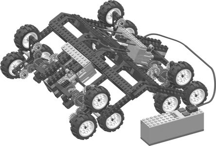
35 Stair-Climber Chapter 1 35 Operating the Stair-Climber Operating the Stair-Climber is relatively straightforward. Pushing the buttons on the battery pack should drive all four wheels forward or backward in unison. I suggest that you experiment and watch how the model drives, steps, and climbs over various obstacles. A pile of LEGO bricks is a perfect, re-configurable obstacle course.try making stairs of various inclines using whatever is convenient. LEGO bricks work well for this, but books and scrap lumber are good alternatives as well. NOTE The CD-ROM that accompanies this book contains video of the Stair-Climber in action traversing various obstacles. Using an RCX instead of a Battery Pack Should you opt to use an RCX instead of the LEGO battery pack, your model might take the form of the Stair-Climber shown in Figure 1.7. Figure 1.7 Stair-Climber Built with an RCX instead of a Battery Box

36 36 Chapter 1 Stair-Climber It is a fairly simple process to modify your Stair-Climber so it is controllable by an RCX. First, you should attach a touch sensor to Input Port A, and second touch sensor to Input Port C, as shown in Figure 1.7.You will then have to modify the Stair-Climber motor wiring as shown.this change connects the left-side motors to Output Port 1 and the right-side motors to Output Port 3. NOTE The wires used for connecting the motors together need to be slightly longer than the ones supplied in the RIS 2.0 set. Use whatever combination of wires you have available to make these connections. Then, by writing a simple program in the language of your choice, assign the following values: Touch Sensor A causes both Output Ports 1 and 3 to be set to reverse and on while pressed. Touch Sensor C causes both Output Ports 1 and 3 to be set to forward and on while pressed. Both Output Ports 1 and 3 are turned off when neither Touch Sensor is pressed. A sample program built with the RIS 2.0 language and programming interface would look something like the program seen in Figure 1.8. Figure 1.8 A Sample Stair-Climber Program Built with RIS 2.0
37 Stair-Climber Chapter 1 37 Summary In this chapter, we have explored the use of a special type of star-wheel configuration designed specifically to overcome severe terrain obstacles including stairs.the model we built demonstrated some of the capabilities of this type of design. Others have used variations of the star-wheel for all terrain vehicles (ATVs) and wheelchairs. Future uses may include autonomous robots that have little difficulty navigating the same environments as we do. If ATVs are of a specific interest to you, I recommend that you jump ahead in the book to Chapter 6, and check out the Shape-Shifting Camera Tank built by Miguel Agulló.
38
How to Build with the Mindstorm Kit
 How to Build with the Mindstorm Kit There are many resources available Constructopedias Example Robots YouTube Etc. The best way to learn, is to do Remember rule #1: don't be afraid to fail New Rule: don't
CONTENTS PROJECT IDEAS 4 ROBO 1 6 ROBO 2 9 PATHFINDER 1 13 PATHFINDER 2 15 ACROBOT 1 17 ACROBOT 2 20 SPECIAL FEATURES. Movement 26.
 The Constructopedia is a building guide for the Robotics Invention System that offers suggestions, hints, and tips to get you started on the CD-ROM Challenges and robotic inventions of your own design.
Deriving Consistency from LEGOs
 Deriving Consistency from LEGOs What we have learned in 6 years of FLL by Austin and Travis Schuh Objectives Basic Building Techniques How to Build Arms and Drive Trains Using Sensors How to Choose a Programming
Chapter 12. Formula EV3: a racing robot
 Chapter 12. Formula EV3: a racing robot Now that you ve learned how to program the EV3 to control motors and sensors, you can begin making more sophisticated robots, such as autonomous vehicles, robotic
LEGO Parts Guide. Naming and Building with LEGO parts. Version 1.3 4/12/10
 LEGO Parts Guide Naming and Building with LEGO parts Version 1.3 4/12/10 Table of Contents Connectors... 4 Friction Pegs... 4 Frictionless Pegs... 5 Ball Joints / Tie Rods... 6 Bushings... 7 Angle Connectors...
ROBOTICS BUILDING BLOCKS
 ROBOTICS BUILDING BLOCKS 2 CURRICULUM MAP Page Title...Section Estimated Time (minutes) Robotics Building Blocks 0 2 Imaginations Coming Alive 5...Robots - Changing the World 5...Amazing Feat 5...Activity
BASIC BUILDING TIPS. Building Tips TABLE OF CONTENTS. Forward 3 plates, beams, Connectors, 5 Bracing and Interlocking 6
 BASIC BUILDING TIPS last updated: June 25 th, 2015 TABLE OF CONTENTS Forward 3 plates, beams, Connectors, 5 Bracing and Interlocking 6 Basics on Gears 8 Types of gears 8 Gears Spacing 9 Simple Gear Ratio
Autonomously Controlled Front Loader Senior Project Proposal
 Autonomously Controlled Front Loader Senior Project Proposal by Steven Koopman and Jerred Peterson Submitted to: Dr. Schertz, Dr. Anakwa EE 451 Senior Capstone Project December 13, 2007 Project Summary:
Wheeled Mobile Robots
 Wheeled Mobile Robots Most popular locomotion mechanism Highly efficient on hard and flat ground. Simple mechanical implementation Balancing is not usually a problem. Three wheels are sufficient to guarantee
Merry-go-round Building Instructions
 Merry-go-round Building Instructions Required parts (L represents length for axles) Attach the ends of two 9x1 beams using an extender pin. Continue connecting the ends of 9x1 beams using extender pins
J&M Mustang Adjustable Panhard Rod (05-09) - Installation Instructions
 - Installation Instructions") J&M Mustang Adjustable Panhard Rod (05-09) - Installation Instructions The below installation instructions work for the following products: J&M Mustang Adjustable Panhard Rod (05-09) Please read through
J&M Mustang Adjustable Panhard Rod (05-09) - Installation Instructions The below installation instructions work for the following products: J&M Mustang Adjustable Panhard Rod (05-09) Please read through
Timing the 9N/2N Steering Sector Gears
 Timing the 9N/2N Steering Sector Gears by John Korschot - www.johnsoldiron.com (May 2010) The procedure for timing a set of steering gears in the 9/2n tractors is published in the I&T FO4 shop manual.
structure table of contents: squarebot chassis parts and assembly 2.2 concepts to understand 2.27 subsystems interfaces 2.37
 The structural subsystem of the robot is responsible for physical support. It holds everything in place, and is, in effect, the durable skeleton of the robot to which all the other subsystems are attached.
Robotic Vehicle Challenge
 Robotic Vehicle Challenge Hello and welcome to your first team challenge! Within this document you will find information about what to expect and prepare for to be successful in your first challenge. In
Enhancing Wheelchair Mobility Through Dynamics Mimicking
 Proceedings of the 3 rd International Conference Mechanical engineering and Mechatronics Prague, Czech Republic, August 14-15, 2014 Paper No. 65 Enhancing Wheelchair Mobility Through Dynamics Mimicking
Charles Flynn s Permanent Magnet Motor.
 Charles Flynn s Permanent Magnet Motor. Patent US 5,455,474 dated 3rd October 1995 and shown in full in the Appendix, gives details of this interesting design. It says: This invention relates to a method
Setup Guide and Chassis Tuning Tips (simple version) By Jim Daniels
 By Jim Daniels") This document is released into the public domain and may be reproduced and distributed in its entirety so long as all credit to Jim Daniels remains. If you find this guide helpful please consider donating
This document is released into the public domain and may be reproduced and distributed in its entirety so long as all credit to Jim Daniels remains. If you find this guide helpful please consider donating
Lab 4: Robot Assembly
 E11: Autonomous Vehicles Lab 4: Robot Assembly In this lab, you ll put together your very own robot! You should have a Mudduino and a chassis, as well as your kit of parts. Now it s time to put them all
Owner s Operator and Maintenance Manual Invacare Rollator
 Owner s Operator and Maintenance Manual Invacare Rollator Important information is contained in this booklet. Please read it carefully before using your Invacare Rollator. Consult your doctor, therapist
Typical mounting of a dial indicator for a radial check. Moog Automotive, Inc.
 Inspect / Service / Test / Replace To find out if the ball joint is loose beyond manufacturer's specifications, use an accurate measuring device. Most load carrying ball joints have a wear limit of 0.060"
Robot Preparation for the VEX World Championship/ US Open. Lessons learned over the past 6 years by David Kelly 2013 VWC, Teacher of the Year
 Robot Preparation for the VEX World Championship/ US Open Lessons learned over the past 6 years by David Kelly 2013 VWC, Teacher of the Year Re-designing Re-designing your robot to a new concept yields
PYRTE. Building The Front Axle, Fork and Steering
 PYRTE Building The Front Axle, Fork and Steering The front axle on this traction engine is a very simple affair, in that it is a rectangular steel rod, sat on edge, with a pivot in the centre, which is
Steeda Sport Mustang Lowering Springs (2005+) - Installation Instructions
 - Installation Instructions") Steeda Sport Mustang Lowering Springs (2005+) - Installation Instructions The below installation instructions work for the following products: Steeda Sport Mustang Lowering Springs (2005+) Please read
Steeda Sport Mustang Lowering Springs (2005+) - Installation Instructions The below installation instructions work for the following products: Steeda Sport Mustang Lowering Springs (2005+) Please read
4TH GEN SEATS IN A 3RD GEN TRUCK
 4TH GEN SEATS IN A 3RD GEN TRUCK by Flopster843 02 Oct 2016 If you drive a 3rd generation Dodge Ram truck, I am sure you have discovered that the OEM seats are not the greatest (Figure 1.) They are extremely
Magnetic Torque Coupling FEA Example
 Magnetic Torque Coupling FEA Example Title: Date of Issue: August 12 th, 2015 Author: Description: FEA Product Example Showcasing Common Options Kevin Kurtz (k.kurtz@quadrantmagnetics.com) Example Finite
User Guide MDS86850E MDS86850EB Rollator
 Supplying Hospitals for Over 90 Years User Guide MDS86850E MDS86850EB Rollator Revised: May 06, 2009 Safety Instructions To ensure your safety in using the Medline rollator, the following safety information
The 2mm Scale Association etched replacement chassis for RTR loco bodies
 The 2mm Scale Association etched replacement chassis for RTR loco bodies Required Parts List Chassis etch (supplied) Motor - for all designs the Association can motor is suitable, alternatives are shown
An Actual Driving Lesson. Learning to drive a manual car
 An Actual Driving Lesson Learning to drive a manual car Where are the controls that I might have to use in my driving: Knowing where the controls are, and being able to locate and use them without looking
POWERTRAX No-Slip Traction System
 POWERTRAX No-Slip Traction System The POWERTRAX Traction Systems are the only differential that offers the maximum traction performance of a locking differential with the smoothness of a limited-slip/posi
THE TORQUE GENERATOR OF WILLIAM F. SKINNER
 THE TORQUE GENERATOR OF WILLIAM F. SKINNER IN 1939, WHICH WAS THE START OF WORLD WAR TWO, WILLIAM SKINNER OF MIAMI IN FLORIDA DEMONSTRATED HIS FIFTH-GENERATION SYSTEM WHICH WAS POWERED BY SPINNING WEIGHTS.
Automata: Putting it all together. Copyright Paul Oh
 Automata: Putting it all together Tentative Schedule 18:00 Guest Lecture 18:30 Lab Putting it All Together : Automata example (The Gymnast) 19:15 Project Time: Form (2-3 person) team; Automata sites and
Dynamics of Machines. Prof. Amitabha Ghosh. Department of Mechanical Engineering. Indian Institute of Technology, Kanpur. Module No.
 Dynamics of Machines Prof. Amitabha Ghosh Department of Mechanical Engineering Indian Institute of Technology, Kanpur Module No. # 04 Lecture No. # 03 In-Line Engine Balancing In the last session, you
A Practical Guide to Free Energy Devices
 A Practical Guide to Free Energy Devices Part PatD20: Last updated: 26th September 2006 Author: Patrick J. Kelly This patent covers a device which is claimed to have a greater output power than the input
Greenpower Challenge. Student support sheet
 Page 1/7 11A Thinking about energy Designing for energy efficiency Energy can be transferred from one place to another. Engineers and scientists have to understand how to manage those transfers in order
All levers are one of three types, usually called classes. The class of a lever depends on the relative position of the load, effort and fulcrum:
 Página 66 de 232 Mechanisms A mechanism is simply a device which takes an input motion and force, and outputs a different motion and force. The point of a mechanism is to make the job easier to do. The
OVERVIEW ENVIRONMENTS. Structures
 OVERVIEW This document is organized into three sections that describe the process of selecting a robotic device for general and specific applications in the transit environment. The first section, Environments,
Gavin Hannah - HND Electronic Engineering Graded Unit Solutions. Christian Hammond, City of Glasgow College. John Woods, City of Glasgow College
 Project Name: SARRRO (Search & Rescue Reconnaissance Rover) Customer: Supervisor: Engineer: Christian Hammond, City of Glasgow College John Woods, City of Glasgow College Gavin Hannah Project Solutions
Cyber Blue FRC 234 FRC 775 Motor Testing WCP 775Pro and AM775 December, 2017
 Cyber Blue FRC 234 FRC 775 Motor Testing WCP 775Pro and AM775 December, 2017 Background In the summer and fall of 2017, Cyber Blue completed a series of FRC motor tests to compare several performance characteristics.
BBK Ceramic Long Tube Headers (99-04 Cobra and Mach 1) - Installation Instructions
 - Installation Instructions") BBK Ceramic Long Tube Headers (99-04 Cobra and 03-04 Mach 1) - Installation Instructions The below installation instructions work for the following products: BBK Ceramic Long Tube Headers (99-04 Cobra
BBK Ceramic Long Tube Headers (99-04 Cobra and 03-04 Mach 1) - Installation Instructions The below installation instructions work for the following products: BBK Ceramic Long Tube Headers (99-04 Cobra
APPENDIX A: Background Information to help you design your car:
 APPENDIX A: Background Information to help you design your car: Solar Cars: A solar car is an automobile that is powered by the sun. Recently, solar power has seen a large interest in the news as a way
INSTALLING A 1977 THRU 1982 C3 STEERING COLUMN INTO A EARLIER 1969 THRU 1976 MODEL CORVETTE
 Last Revised: 23FE2011 INSTALLING A 1977 THRU 1982 C3 STEERING COLUMN INTO A EARLIER 1969 THRU 1976 MODEL CORVETTE Why Make This Installation Starting in 1977 and carrying thru 1982, the C3 Corvette steering
E. V. Gray Historical Series
 E. V. Gray Historical Series Secrets of the EMA4 and EMA5 Control Commutators (Still Unresolved) Mark McKay, PE While the technical revelations provided by the disassembly of Mr. Gray s custom electromagnets
Chapter 2. Battery Charger and Base Assembly
 Chapter 2 Battery Charger and Base Assembly 11 CHAPTER 2. BATTERY CHARGER AND BASE ASSEMBLY 2.1 Section Overview This Lab teaches students how to assemble a Tekbot, in the following steps: Describe the
Simple Free-Energy Devices
 Simple Free-Energy Devices There is nothing magic about free-energy and by free-energy I mean something which produces output energy without the need for using a fuel which you have to buy. Chapter 11:
A Study of the Botball Kit and Suggestions for Improvement
 A Study of the Botball Kit and Suggestions for Improvement Alia ElKattan Hayah International Academy Cairo, Egypt aliaelkattan@hotmail.com Abstract This paper will explore some of the changes that the
2005 GM/ISUZU TRUCK 50 (Weight Distribution Concepts Section continued from previous page) Basic Formulas
 Basic Formulas") 2005 GM/ISUZU TRUCK 50 Basic Formulas (a) W x D = W f x (c) = (A + B + C + D) = (F + D) or (b) W x F = W r x (d) W = W f x W r 1. W f = W x D 2. D = W f x W 3. = W x D W f 4. W = W f x D 5. W r = W x F
2005 GM/ISUZU TRUCK 50 Basic Formulas (a) W x D = W f x (c) = (A + B + C + D) = (F + D) or (b) W x F = W r x (d) W = W f x W r 1. W f = W x D 2. D = W f x W 3. = W x D W f 4. W = W f x D 5. W r = W x F
CHAPTER 6 GEARS CHAPTER LEARNING OBJECTIVES
 CHAPTER 6 GEARS CHAPTER LEARNING OBJECTIVES Upon completion of this chapter, you should be able to do the following: Compare the types of gears and their advantages. Did you ever take a clock apart to
MOTORS. Part 2: The Stepping Motor July 8, 2015 ELEC This lab must be handed in at the end of the lab period
 MOTORS Part 2: The Stepping Motor July 8, 2015 ELEC 3105 This lab must be handed in at the end of the lab period 1.0 Introduction The objective of this lab is to examine the operation of a typical stepping
Newton Scooters TEACHER NOTES. Forces Chapter Project. Materials and Preparation. Chapter Project Overview. Keep Students on Track Section 2
 TEACHER NOTES Lab zonetm Newton Scooters The following steps will walk you through the. Use the hints as you guide your students through planning, construction, testing, improvements, and presentations.
Cool Parts on BrickLink
 Page 1 of 6 Awesome Lego parts that can win you an FLL tournament Over the years there have been thousand of parts made by LEGO. You can find them at and many can give you a competitive advantage. Jonathan
NEW CAR TIPS. Teaching Guidelines
 NEW CAR TIPS Teaching Guidelines Subject: Algebra Topics: Patterns and Functions Grades: 7-12 Concepts: Independent and dependent variables Slope Direct variation (optional) Knowledge and Skills: Can relate
Mustang CDC Lightbar (94-04) - Installation Instructions
 - Installation Instructions") Mustang CDC Lightbar (94-04) - Installation Instructions The below installation instructions work for the following products: Classic Design Concepts Mustang Convertible Lightbar (94-04 Carbon Fiber) Classic
Mustang CDC Lightbar (94-04) - Installation Instructions The below installation instructions work for the following products: Classic Design Concepts Mustang Convertible Lightbar (94-04 Carbon Fiber) Classic
FULL FLOATER HUB KIT INSTRUCTION MANUAL
 FULL FLOATER HUB KIT INSTRUCTION MANUAL WARNING: All components are shipped assembled for illustration purposes only. IT IS YOUR RESPONSIBILITY FOR FINAL ASSEMBLY. Please read instructions thoroughly before
How To: Fix That Ugly Hanging E-Brake Cable A CFans Members Mod Project by dirtydawg
 How To: Fix That Ugly Hanging E-Brake Cable A CFans Members Mod Project by dirtydawg Skill Level: Easy Disclaimer: Please use caution and seek professional assistance when necessary. ColoradoFans.com,
motion table of contents: squarebot assembly 3.2 concepts to understand 3.3 subsystems interfaces 3.21 motion subsystem inventory 3.
 The subsystem of the robot is responsible for exactly that,. It includes both the motors that generate, and the wheels and gears that transfer and transform that into the desired forms. With the structural
HOUSING REPORT NORTHWEST MICHIGAN YEAR END 2018
 NORTHWEST MICHIGAN Northwest Michigan 218 Highlights Waterfront Non-Waterfront : dropped 2% from last year to the lowest level in the past 4 years : had a slight decline of 3% from the prior year. Average
LEGO Element Survey 45560
 1 Bushing, ½-module, yellow 4239601 4 Bushing, 1-module, gray 4211622 170x Connector peg with friction, 2-module, 4121715 Connector peg, 1½-module, beige 6013938 Axle with positioning stop, 4-module, beige
Reliable Reach. Robotics Unit Lesson 4. Overview
 Robotics Unit Lesson 4 Reliable Reach Overview Robots are used not only to transport things across the ground, but also as automatic lifting devices. In the mountain rescue scenario, the mountaineers are
Installation Instructions
 Installation Instructions Product: SwitchBlade Swaybar System Part Number: PN 9100 Application: Jeep Wrangler TJ, 1997-06 (front) Welcome CONGRATULATIONS on purchasing a SwitchBlade Swaybar System from
The stair climber for your wheelchair 0OWERFUL SAFE AND COMFORTABLE UPSTAIRS AND DOWNSTAIRS.
 The stair climber for your wheelchair 0OWERFUL SAFE AND COMFORTABLE UPSTAIRS AND DOWNSTAIRS www.aat-online.de In everyday situations stairs pose a problem for many people. Be it in school, at work or on
WIDE TIRE BEAD HELP. Problem: The inside edge of the tire bead is very. Wheel & Tire Accessories
 WIDE TIRE BEAD HELP Problem: The inside edge of the tire bead is very sharp. This is accentuated with large tires that have wider than normal beads. This applies to Interco, Maxxis, BFG, ProComp, Goodyear
Step #1 From your spool of 18 gauge primary wire, cut between 11 and 21 three inch strips of wire. You will only need 11 for the ROV, but it is good t
 How to make a ROV! Step #1 From your spool of 18 gauge primary wire, cut between 11 and 21 three inch strips of wire. You will only need 11 for the ROV, but it is good to have extras. Using the wire cutter,
Topic: Friction. Planes, Trains, and Automobiles. A Poppins Book Nook Science Experiment. My Name Is:
 Planes, Trains, and Automobiles A Poppins Book Nook Science Experiment Topic: Friction My Name Is: ---------------------------------------------------------------------------------------------------------
Revision 4 May 23, 2018
 Kalsi Seals Handbook Chapter C16 Plastic lined Kalsi Seals Revision 4 May 23, 2018 Individual chapters of the Kalsi Seals Handbook are periodically updated. To determine if a newer revision of this chapter
An Actual Driving Lesson Learning to drive an automatic car
 An Actual Driving Lesson Learning to drive an automatic car Where are the controls that I might have to use in my driving: Knowing where the controls are, and being able to locate and use them without
Name Date Period. MATERIALS: Light bulb Battery Wires (2) Light socket Switch Penny
 Light socket Switch Penny") Name Date Period Lab: Electricity and Circuits CHAPTER 34: CURRENT ELECTRICITY BACKGROUND: Just as water is the flow of H 2 O molecules, electric current is the flow of charged particles. In circuits of
Name Date Period Lab: Electricity and Circuits CHAPTER 34: CURRENT ELECTRICITY BACKGROUND: Just as water is the flow of H 2 O molecules, electric current is the flow of charged particles. In circuits of
THE MOTOR/GENERATOR OF ROBERT ADAMS
 THE MOTOR/GENERATOR OF ROBERT ADAMS WHEN HE WAS 70 YEARS OLD, ROBERT ADAMS OF NEW ZEALAND DESIGNED A VERY EFFECTIVE MOTOR/GENERATOR. HE WAS TOLD TO DESTROY HIS DEVICE OR HE WOULD BE KILLED. ROBERT DECIDED
The Design of an Omnidirectional All-Terrain Rover Chassis
 The Design of an Omnidirectional All-Terrain Rover Chassis Abstract Submission for TePRA 2011: the 3rd Annual IEEE International Conference on Technologies for Practical Robot Applications Timothy C. Lexen,
DC Series Installation Manual (# )
") DC Series Installation Manual (# 101630) Page 1 of 33 In this booklet you will find: TOWER INSTALLATION... 3 U-Bolt Style mount... 4 Side Frame Style mount... 4 PIVOT INSTALLATION... 5 External Pivot Installation:
DC Series Installation Manual (# 101630) Page 1 of 33 In this booklet you will find: TOWER INSTALLATION... 3 U-Bolt Style mount... 4 Side Frame Style mount... 4 PIVOT INSTALLATION... 5 External Pivot Installation:
Appalachian Power Company Policy No. 15: Ladder Setup. 1) Statement of policy:
 Statement of policy:") Appalachian Power Company Policy No. 15: Ladder Setup 1) Statement of policy: The use of ladders by employees is required to accomplish a variety of tasks on a routine basis. By properly carrying, setting
Appalachian Power Company Policy No. 15: Ladder Setup 1) Statement of policy: The use of ladders by employees is required to accomplish a variety of tasks on a routine basis. By properly carrying, setting
Connecting the rear fog light on the A4 Jetta, while keeping the 5 Light Mod
 Connecting the rear fog light on the A4 Jetta, while keeping the 5 Light Mod DISCLAIMER: I'm human and make mistakes. If you spot one in this how to, tell me and I'll fix it This was done on my 99.5 Jetta.
STEERING SYSTEM Introduction
 STEERING SYSTEM Introduction The steering makes it possible to change direction. The steering must be reliable and safe; there must not be too much play in the steering. It must be possible to steer accurately.
J&M Mustang Rear Lower Control Arms (2005+) - Installation Instructions
 - Installation Instructions") J&M Mustang Rear Lower Control Arms (2005+) - Installation Instructions The below installation instructions work for the following products: J&M Mustang Rear Lower Control Arms (2005+) Please read through
J&M Mustang Rear Lower Control Arms (2005+) - Installation Instructions The below installation instructions work for the following products: J&M Mustang Rear Lower Control Arms (2005+) Please read through
7211 A-ARM FRONT, 4-LINK, 3 X 2 FRAME, INTERMEDIATE, ELIMINATOR CHASSIS ITEM QTY SIZE/PART NO. TUBE CODE DESCRIPTION
 #917211 Page 1 of 6 7211 A-ARM FRONT, 4-LINK, 3 X 2 FRAME, INTERMEDIATE, ELIMINATOR CHASSIS ITEM QTY SIZE/PART NO. TUBE CODE DESCRIPTION 1 2 4138 Cage Side 2 2 4208 Forward strut 3 1 4038 Main Hoop 4 1
2011+ Adjustable Tie-rod Ends (Mm5TR-2)
") 3430 Sacramento Dr., Unit D San Luis Obispo, CA 93401 Telephone: 805/544-8748 Fax: 805/544-8645 www.maximummotorsports.com 2011+ Adjustable Tie-rod Ends (Mm5TR-2) Instructions 1. Set the parking brake
3430 Sacramento Dr., Unit D San Luis Obispo, CA 93401 Telephone: 805/544-8748 Fax: 805/544-8645 www.maximummotorsports.com 2011+ Adjustable Tie-rod Ends (Mm5TR-2) Instructions 1. Set the parking brake
SAE Mini BAJA: Suspension and Steering
 SAE Mini BAJA: Suspension and Steering By Zane Cross, Kyle Egan, Nick Garry, Trevor Hochhaus Team 11 Progress Report Submitted towards partial fulfillment of the requirements for Mechanical Engineering
I N S TA L L AT I O N G U I D E
 INSTALLATION GUIDE TM Installation Guide Contents Page Open Differential Part Identification & Terminology... 2 Powertrax No-Slip Differential Exploded View... 3 Vehicle Preparation for Installation (steps
SYNCHRONIZE YNCHRONIZER AUTOMATIC TIC TROUBLESHOOTING GUIDE RELAY ASSEMBLY SOLENOID (MODEL 1750) LIMIT SWITCH ENGINE CABLE CABLE TO
 LIMIT SWITCH ENGINE CABLE CABLE TO") YNCHRONIZER SYNCHRONIZE AUTOMATIC TIC TROUBLESHOOTING GUIDE SOLENOID (MODEL 1750) RELAY ASSEMBLY LIMIT SWITCH ENGINE CABLE CABLE TO ENGINE THROTTLE RED COLLAR ADJUST LIMIT SWITCH OPERATION BRIDGE CABLE
YNCHRONIZER SYNCHRONIZE AUTOMATIC TIC TROUBLESHOOTING GUIDE SOLENOID (MODEL 1750) RELAY ASSEMBLY LIMIT SWITCH ENGINE CABLE CABLE TO ENGINE THROTTLE RED COLLAR ADJUST LIMIT SWITCH OPERATION BRIDGE CABLE
 YNCHRONIZER AUTOMATIC SYNCHRONIZE TROUBLESHOOTING GUIDE SOLENOID (MODEL 1750) RELAY ASSEMBLY LIMIT SWITCH ENGINE CABLE CABLE TO ENGINE THROTTLE RED COLLAR ADJUST LIMIT SWITCH OPERATION BRIDGE CABLE CONTROL
I N S TA L L AT I O N G U I D E
 INSTALLATION GUIDE TM Installation Guide Contents Page Open Differential Part Identification & Terminology... 2 Powertrax No-Slip Differential Exploded View... 3 Vehicle Preparation for Installation (steps
The Life of a Lifter, Part 2
 Basics Series: The Life of a Lifter, Part 2 -Greg McConiga Last time we looked at some complicated dynamics and compared flats to rollers. Now for the hands-on. 6 FEATURE This off-the-shelf hydraulic lifter
Rear Strong-Strut. Installation Instructions
 Rear Strong-Strut Installation Instructions Please read instructions completely before installing the rear Strong-Strut Forward Installation of the rear Strong-Strut is quite simple and involves the removal
Supplying Hospitals for Over 90 Years. User Guide MDS86825SLR. Ultra-Light Rollator
 Supplying Hospitals for Over 90 Years User Guide MDS86825SLR Ultra-Light Rollator Revised: July 1, 2008 Contents Ultra-Light Rollator Features... 3 Rollator Components... 4 Safety Instructions... 5 Assembly
DESIGN AND TECHNOLOGY
 Candidate Name Centre Number 0 Candidate Number GCSE 142/04 DESIGN AND TECHNOLOGY PAPER 2 FOCUS AREA: SYSTEMS AND CONTROL TECHNOLOGY Higher Tier A.M. MONDAY, 2 June 2008 1 1 2 hours Leave Blank Question
Basic Steel Rollator with 6" Wheels Knockdown Rolling Walker
 Basic Steel Rollator with 6" Wheels Knockdown Rolling Walker User Instructions & Warranty MDS86850ESKD Latex Free 2 Table of Contents Safety Instructions... 4 Rollator Parts List... 5 Assembly Instructions...
Traction changes on uneven ground. Diagonal traction loss
 Traction changes on uneven ground Diagonal traction loss Whenever one of the wheels on a car leaves its level position (up or down) the diagonally opposed wheel will react similarly. This is most pronounced
Hello and welcome to training on general purpose motor drivers in the 3 to 15 volt range. I m Paul Dieffenderfer & I will be your host for this
 Hello and welcome to training on general purpose motor drivers in the 3 to 15 volt range. I m Paul Dieffenderfer & I will be your host for this presentation prepared by H. Tanaka of the LSI Division. 1
The 01 in LEGO. The 01001, built in 1925
 The 01001, built in 1925 The 01 in LEGO The BR01 was one of the first german Einheitslokomotiven (unified engines, BR ~ Baureihe ~ building series, 0 ~ express passenger). In the 19th century all german
INSTALLATION INSTRUCTIONS
 Product: Switchblade Swaybar System Part Number: JKS9100 INSTALLATION INSTRUCTIONS Applications: Wrangler TJ, 1997-06 (front) 517-278-1226 tech@jksmfg.com www.jksmfg.com 491 W. Garfield Avenue, Coldwater,
7256 INSTRUCTIONS FOR ELIMINATOR II A-ARM FRONT, 4-LINK REAR, MILD STEEL, INTERMEDIATE, SERIES CHASSIS
 #917256 Page 1 of 7 7256 INSTRUCTIONS FOR ELIMINATOR II A-ARM FRONT, 4-LINK REAR, MILD STEEL, INTERMEDIATE, SERIES CHASSIS ITEM QTY SIZE/PART NO. TUBE CODE DESCRIPTION 1 2 4138 Cage Side 2 2 4208 Forward
BASIC STEEL ROLLATOR WITH 6" WHEELS KNOCKDOWN ROLLING WALKER
 BASIC STEEL ROLLATOR WITH 6" WHEELS KNOCKDOWN ROLLING WALKER USER INSTRUCTIONS & WARRANTY 100RA Product is not made with natural rubber latex. 2 Revised: 09/20/2016 Table of Contents Safety Instructions...4
Wine Glass Orchestra. Leah Buechley CSCI 7000 Things That Think
 Wine Glass Orchestra Leah Buechley CSCI 7000 Things That Think Abstract My wine glass orchestra project consists of three mechanical wine glass instruments coordinated with Crickets. The first automaton,
SHAFT ALIGNMENT FORWARD
 Service Application Manual SAM Chapter 630-76 Section 24 SHAFT ALIGNMENT FORWARD One of the basic problems of any installation is aligning couplings or shafts. Therefore, this section will endeavor to
Steam Car Developments and Steam Aviation
 c Steam Car Developments and Steam Aviation Vol. VIII FEBRUARY, 19 W No. 96 Progress Report on the Leslie Steam Car. Those of our readers who have been following' the Magazine since the October, 1937,
ALIGNING A 2007 CADILLAC CTS-V
 ALIGNING A 2007 CADILLAC CTS-V I ll describe a four-wheel alignment of a 2007 Cadillac CTS-V in this document using homemade alignment tools. I described the tools in a previous document. The alignment
The following information is gathered from pages of the Honda Aero Shop Manual.
 Original write-up by W. Boyter The following information is gathered from pages 3.10-3.12 of the Honda Aero Shop Manual. First of all, pull all your spark plugs, make sure your transmission is in neutral.
Supra and Supra Linea Platform Lifts
 2 Access BDD Supra and Supra Linea Platform Lifts FOR STRAIGHT AND CURVED STAIRCASES Our Inclined Platform Lifts are manufactured to meet the needs of customers who demand the best comfort and quality.
MODULE 4 Seat Belt Systems
 Topic National Child Passenger Safety Certification Training Program MODULE 4 Seat Belt Systems Module Agenda: 130 Minutes Suggested Timing 1. Introduction 2 2. Federal Standards for Seat Belts 3 3. Types
Linear Shaft Motors in Parallel Applications
 Linear Shaft Motors in Parallel Applications Nippon Pulse s Linear Shaft Motor (LSM) has been successfully used in parallel motor applications. Parallel applications are ones in which there are two or
INSTRUCTIONS FOR STRUT FRONT, 4-LINK REAR, ROADSTER CHASSIS
 #917406 Page 1 of 5 7406 INSTRUCTIONS FOR STRUT FRONT, 4-LINK REAR, ROADSTER CHASSIS ITEM QTY SIZE/PART NO. TUBE CODE DESCRIPTION 1 1 4215 Front frame rail strut 1 5/8 (pair) 2 1 4236 Roadster firewall