Welding Positioner Model: LD-60R/150R/300R
|
|
|
- Dale Cook
- 5 years ago
- Views:
Transcription
1 Welding Positioner Model: LD-60R/150R/300R Operating Instructions IMPORTANT Carefully read and understand these operating instructions, as well as instructions for operating ancillary equipment, before operating, inspecting, or servicing this product.
2 Table of Contents 1. SAFETY INFORMATION PACKING LIST MACHINE OVERVIEW INSTALLATION OPERATIONS PRECAUTIONS ON HANDLING MOUNTED OBJECTS MAINTENANCE AND INSPECTIONS TROUBLESHOOTING WARRANTY CABLE SYSTEM DIAGRAM EXTERNAL AND ASSEMBLY DIAGRAMS OF THE MAIN UNIT

 Whenever the welding machine is ON, electricity flows through the welding rod (or wire), workpiece, and positioner.")
3 1. Safety Information Be sure to read the following. WARNING: Be sure to also read the operating instructions for the welding machine and other ancillary equipment before using this product, and protect operators and those around you from accident. Electric shock prevention: Note that electric shock can lead to serious accident. 1) When handling this product, always wear dry, insulating gloves, shoes, and clothing. 2) Whenever the welding machine is ON, electricity flows through the welding rod (or wire), workpiece, and positioner. If your skin or wet clothing comes into contact with the current-carrying part, you risk receiving an electric shock. 3) Shut off the main power supply when not using this product, or when conducting repairs and inspections. 4) Do not place this product in places subject to high humidity or on a wet floor. 5) Attach the earth conductor properly. 6) Be sure to install a fuse or breaker of a designated capacity to the power supply side. Prevention of injury to eyes and skin: Welding arcs and spatters release strong UV rays and temperatures that can injure your eyes and skin. 1
 To prevent burn injury, always wear long gloves, a safety hat, and appropriate clothing, and make sure no skin is exposed.")
 Do not inhale fumes and gases.")

4 1) To protect your eyes and face, always wear protective equipment (glasses, goggles, helmet, etc.) that provide a shading effect appropriate to the welding unit. 2) To prevent burn injury, always wear long gloves, a safety hat, and appropriate clothing, and make sure no skin is exposed. 3) Warn those around you to wear appropriate protective equipment (glasses, goggles, helmet, etc.). We also recommend using protective screens and curtains. Fume and gas disaster: Fumes and gases that are generated during welding are hazardous. 1) Do not inhale fumes and gases. Protect your head from covering fumes and gases during welding, and fully ventilate the workplace. When welding materials that contain, or are plated with, metals such as zinc, lead, and cadmium, toxic fumes may be generated. Take additional precautions, and install effective smoke-extraction equipment. 2) Do not place nearby, or use, chlorinated solvents while performing welding work. Vapors from chlorinated solvents may react with the heat and sparks from welding arcs and produce toxic gas phosgene or other irritating substances. Prevention of explosion accidents 1) Do not weld containers filled with flammable substances. The container may explode. 2) Follow proper and appropriate procedures when welding tanks and drums, as flammable or toxic fumes may be generated during welding. 3) Do not conduct welding work in an atmosphere contaminated by explosive gases, mists, or dust. Fire prevention: Sparks and spatters that are generated during welding may produce flames. When welding, they may spatter the vicinity and encroach on the neighboring area through small cracks and holes. 2
 Do not place just-welded metals near flammables. 4) Ventilate atmospheres that contain combustible gas or flammable liquid mists and dust.")
5 1) Prepare fire extinguishers or items that can effectively extinguish fire. 2) Move flammables away from the welding worksite, out of reach of welding sparks and spatters. 3) Do not place just-welded metals near flammables. 4) Ventilate atmospheres that contain combustible gas or flammable liquid mists and dust. 5) Even when not welding, excessive heating and fire may occur from the welding rod (or wire), workpieces, positioner, or connections. Usage precautions 1) Always wear a safety hat, protective glasses, and safety shoes during installation, operation, and maintenance/inspection. 2) Attach workpieces properly. (See 6. Precautions on Handling Mounted Objects.) 3) While operating this product, be careful of accidents caused by touching rotating parts or by body parts, clothing, cables, etc. getting caught in the machine. 4) Do not dismantle this product when an object is still attached to the table. 5) Always keep safety guards and covers in their respective positions on the product. Do not remove them necessarily, or use them if they are damaged. 6) Regularly inspect this product, and repair any faults before using it. IMPORTANT: Legally-restricted tasks should only be conducted by qualified personnel. 1) Arc welding 2) Gas welding 3) Electrical work 4) Crane or forklift operation 5) Lifting work 6) Handling high-pressure gas or conducting high-pressure gas fitting work 3
6 4
7 2. Packing List 1) Confirming the supplied items Before using this product, check whether you have the following items. In the event an item is lacking, please contact the dealer where you have purchased the product. 2) List of items supplied Name Quantity Remarks Positioner main unit 1 Control unit 1 Power cable 1 Foot switch 1 Operating Instructions 1 This manual 3. Machine Overview The positioner is a product that helps position a workpiece for steady welding. It rotates a table using a motor, and lets you set a speed appropriate to the welding work with the control unit dial, and start/stop the rotation with a foot switch. The table can be set to the necessary tilt angle using the tilt fixation handle. Main specifications LD-60R LD-150R LD-300R Max. load [kg] Horizontal Vertical Power supply AC single-phase 100V 50/60Hz External dimension [mm] Width Depth Height Table diameter [mm] φ300 φ380 φ450 Table rotation Min [rpm] Max Table tilt angle -135 to to 90 Center of gravity Height during max. load [mm] Eccentricity Table height in horizontal position [mm] Tilt axis height [mm] Weight of main unit [kg] Allowable welding current [A] 500 5
8 6
 Flat floor that is strong enough to support the weights of the mounted items and the positioner. If the floor is weak, unbalanced loads may cause the positioner to fall over.")
9 4. Installation 1) Confirming the packaged components See 2. Packing List. 2) Installation location (1) Well-ventilated locations Fumes and gases must be ventilated during welding. (2) Flat floor that is strong enough to support the weights of the mounted items and the positioner. If the floor is weak, unbalanced loads may cause the positioner to fall over. (3) Do not place the positioner in the following locations: Locations subject to rain On a wet floor Locations subject to high temperatures Locations near dangerous inflammable objects Locations where welding sparks and spatters may cause fire WARNING: Beware of electric shock from steel plates. When installing the positioner on a steel floor, protect the operator s body with insulating material, and insulate the workpiece and positioner from the operator. 3) Equipment installation (1) Installing the main unit Place the main unit in a flat installation location. Secure the unit by inserting anchor bolts in the two holes toward the back of the main unit. Adjust the level with the two vertical adjusting bolts, so that the unit does not wobble. If the main unit is not steady, it may sway during operations. This is very dangerous, and may also cause the machine to fall over. (2) Connecting the operation unit (pendant switch) Connect the relay cable of the operation unit to the control unit on the main unit. Secure the connection with a screw. (3) Connecting the foot switch Connect the relay cable of the foot switch to the control unit on the main unit. Secure the connection with a screw. 7
10 4) Earth conductor and welding earth cable (1) Properly connect the earth conductor on the positioner main unit (labeled with a sticker). (2) Directly attach the welding earth cable for the welding machine power supply to the welding earth cable connector on the leg of the positioner, and secure it with a bolt. M8 bolt Welding earth cable Welding earth cable attachment diagram WARNING: Be sure to connect the earth conductor, to prevent an electric shock accident in the event of a short circuit. 1) Work involving an earth conductor or ground-fault interrupter requires specialized work (by an electrician). 2) To connect an earth conductor or ground-fault interrupter, observe technical criteria for electric facilities. 3) When using an existing earth terminal, check whether it provides sufficient earth connection. 5) Connecting the power supply Use specified power supply only. The standard specification is 100V, 50/60Hz. To ensure safety, strictly observe our safety standards for matters not sufficiently described herein. 8
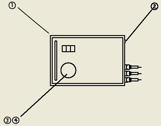
11 CAUTION 1) Route the power supply cable so that it will not be stepped on. Also be careful not to place anything on the cable. 2) Install a switch that can interrupt the power supply or a thermal breaker. 3) Connect the power supply cable only after confirming the safety of the surrounding area. 4) Ground the power supply cable properly, and fully plug it into its receptacle. 5) Do not connect the earth conductor to a conduit, gas pipe, or flammable liquid pipe system. 6) Supply power only after confirming that the toggle switch is off. 5. Operations 1) Control unit functions The control unit contains a lamp that lights when operational power is on and a speed setter for adjusting rotation direction and speed. SPEED SELECT HI MID POWER SW MOTOR FUSE 3A POWER FUSE 3A LOW SPEED POWER Positioner Controller LD R-A 9
12 10

 Lights when power is on. 5 Dial SPEED Sets the table rotation speed.")
13 No Display Type Function 1 Lock switch Switches the main power supply on/off. 2 Toggle switch Switches the table rotation direction. 3 Rotary switch Switches the table rotation speed. LOW: (near) 0 low rotation speed MID : (near) 0 medium rotation speed HI : (near) 0 high rotation speed Note: The machine may not stop even when the speed adjusting dial is set to MIN. 4 Lamp (white) Lights when power is on. 5 Dial SPEED Sets the table rotation speed. Turning the dial clockwise increases the speed. 6 Foot switch Rotates the table when pressed, and stops the rotation when released. 11
14 2) Operational procedure Operate the machine as described below. Operation unit 1 Turn on your company s main power switch and the power to the operation unit. 4 Select a rotation direction using the rotation direction changeover switch. Main unit 2 Make the table horizontal, and attach a workpiece to the table. 3 Loosen the tilt fixation handle to set the table angle, then re-tighten the handle. (For LD-60R) Turn the tilt fixation handle and adjust the table angle. (For models other than LD-60R) 5 Set the rotation speed adjustment dial to minimum. 6 7 Step on the foot switch to rotate the table. Adjust the rotation speed using the rotation speed adjustment dial. 8 Perform welding work by operating the foot switch. 10 Turn off the operation unit. 9 Make the table horizontal, and remove the workpiece. Precautions when using a TIG welding machine This machine is made to control TIG welding noise, but to ensure safety, be sure to observe the following precautions. 1) Use separate power supplies for the main unit and welding power. 2) During operations, do not allow the main unit cable and torch cable to cross each other. Precautions when switching speed and rotation 12
15 1) Do not change the rotation direction while the table is rotating. Doing so may cause the machine to malfunction. 2) Stop the table rotation before switching the speed. Switching the speed while the table is rotating is dangerous, as the speed may suddenly increase. 13
 When conducting attachment work, always wear a helmet, protective glasses, and safety shoes. 2) Attach and align workpieces properly.")
16 6. Precautions on Handling Mounted Objects WARNING: Mounted objects may fall or move, and cause serious accident or damage the product. 1) When conducting attachment work, always wear a helmet, protective glasses, and safety shoes. 2) Attach and align workpieces properly. 3) When rotating the table, pay special care to the surrounding area and make sure there are no impediments. CAUTION 1) When placing a workpiece on the table (and particularly when using a crane or other machine), be careful not to create a large impact. 2) Do not place a load exceeding the allowable load on the table. Operating the machine with an overload may burn out or damage the motor and control devices. 3) An unbalanced load may cause uneven rotation and interfere with the welding beat. If this happens, attach a balance weight. However, make sure the balance weight does not cause an overload. θ: Tilt angle E: Eccentricity of the center of gravity T: Rotation torque H: Height of the center of gravity W: Load weight: The weight of all objects on the table (including the chuck, attachment fittings, etc.) E: Eccentricity of the center of gravity: Distance from the center of the table to the center of gravity of the mounted object T: Rotation torque: Load weight eccentricity of the center of gravity H: Height of the center of gravity: Distance from the top of the table to the center of gravity of the mounted object Calculating allowable load weight and eccentricity when the table is vertical 14
17 Use the machine in a state where load weight eccentricity of the center of gravity is less than maximum rotation torque. LD-60R LD-150R LD-300R W: Max. load Horizontal weight [Kg] Vertical H: Height of center of Center of gravity of gravity max. load [mm] E: Eccentricity of center of gravity Allowable rotation torque Kg mm
18 7. Maintenance and Inspections Conduct maintenance and inspections, and always use this machine in best condition. WARNING 1) Conduct periodic maintenance and inspections on this machine. 2) If any faults are found, be sure to remedy them before use. 3) Have this machine inspected by personnel who possesses sufficient knowledge of electrical matters and comprehensive knowledge of this type of maintenance inspection. 4) When repairing or inspecting the machine, shut off the main power supply or unplug the power supply cable. 5) Do not conduct maintenance or inspections while an object is still attached to the table. 6) When the machine has been repaired, make sure all repairs have been completed and the machine works properly, before use. 1) Daily inspection Inspection items Is there any adhesion of foreign matter on the top surface of the table? Is the operation unit dirty? Does the foot switch move smoothly? Is there any damage to the cables? Countermeasures in the event of an abnormality Remove the foreign matter. Clean the operation unit. If not, replace or clean the foot switch. If so, replace or repair the relevant cable. CAUTION: Repair cable damage immediately upon discovery. 16
19 2) Periodic inspection Inspection location Table rotation Table rotation bearing Table tilt mechanism Reduction gear Inspection item Is there any foreign matter stuck between the gears? Is the backlash precision appropriate? Is the table steady? Countermeasures in the event of an abnormality Clean and remove the foreign matter. Tighten and adjust the bearing nut on the spindle. Is the table axis steady? If not, replace the bearing inside the bearing housing of the table. Does the table tilt smoothly? If not, remove spatters, etc. and apply grease. Check the oil level gauge of the Replenish oil. reduction gear. Is the oil degraded? If so, replace the oil. Reduction gear oil Ambient temperature -15 C to 5 C 5 C to 40 C ISO viscosity grade (ISOVG) VG 320 VG 460 Exxon Mobile Mobile Gear 632 Mobile Gear 634 Cosmo Oil Cosmo Gear SE 320 Cosmo Gear SE 460 Idemitsu Kosan Daphne Super Gear Oil 320 Daphne Super Gear Oil 460 Showa Shell Sekiyu Omala Oil 320 Omala Oil 460 Nippon Oil Bonnock M 320 Bonnock M 460 Japan Energy JOMO Reductase 320 JOMO Reductase 460 CAUTION 1) A welding current flows through the rotation spindle of the table. Tighten and adjust the spindle so that it is tighter than normal. If it is not tightened strongly, the contact points will produce sparks and damage the bearing. 2) Immediately wipe away any oil that has spilled. Additionally, properly dispose of objects that have oil on them. 17
20 8. Troubleshooting Dealing with mechanical problems Symptom Cause Remedy The table does not rotate. (1) Insufficient tightening of the metal plug of the connecting cable (2) Disconnection of the connecting cable (3) Switch or foot switch malfunction (4) Control unit malfunction (5) Motor burnout (6) Burning of the gear tooth surface (7) Spindle key damage (8) Bearing damage (1) Tighten securely. (2) Replace the cable. (3) Replace the switch component. (4) Replace the control unit. (5) Replace the motor. (6) Replace. (7) Replace the key. (8) Replace the bearing. The table does not rotate smoothly. The lubricant leaks. Welding failure Note: In regard to items (4) and (5), pursue and eliminate the cause before taking the countermeasure and replacing the component. (1) The bearing has burned out (1) Replace the bearing. due to an overcurrent of the welding current. (2) Spatters and slugs are adhered (2) Clean and apply grease to to the rotation drive unit. the rotation drive unit. (3) The carbon brush on the motor (3) Replace and adjust the is worn or not properly carbon brush. connected. (4) A load greater than the (4) Use the table within the allowable load is placed on the allowable load limit. table. (5) The center of gravity of the (5) Attach a counterweight. workpiece is eccentric. (1) Oil seal damage (2) Packing defect (3) Insufficient tightening of the waste oil plug (4) Oil gauge damage (1) The welding table earth cable is not securely connected. (2) The bearing nut is loose and has created a gap between the inner and outer wheels of the tapered roller. (1) Replace the oil seal. (2) Replace the packing. (3) Securely tighten the plug. (4) Replace the oil gauge. (1) Securely connect the earth cable. (2) Tighten the bearing nut. 18
21 9. Warranty 1) When a failure has occurred Before calling for repair service, read the instructions on maintenance/inspections and troubleshooting provided in this manual, and take the appropriate measures. If the cause is unclear, please consult with your dealer or our sales offices. 2) Warranty The warranty term for this product is a year from the date of purchase. In the event a malfunction occurs, we will promptly repair it and return it to its original complete state. However, please note that some repairs may not be free of charge, even if they are made during the inspection period. For repairs needed after the expiration of the warranty term, please consult with your dealer or our sales offices. If a damaged function can be restored by repairing it, we will undertake the repair by request from our customer, for a fee. Please note that we will not be responsible for accidents and malfunctions that occur as a result of a repair or supply of components by companies other than our company or our designated partner companies. 3) Term of warranty for parts We will continue to retain performance parts for maintenance of this welding positioner for at least 6 years after termination of their production. 19
22 20
23 10. Cable System Diagram Positioner Control unit Foot switch CTS 3x0.75, approx.1.2m CTS 3x0.75, approx. 1m CTS 3x0.75, approx. 5m Input power supply AC 100V 50/60Hz 21
24 11. External and Assembly Diagrams of the Main Unit External diagram of LD-60R φ
25 23
26 External diagram of LD-150R φ
27 25
28 External diagram of LD-300R φ 450??
29 LD-60R (1/2) 27
30 LD-60R (2/2) 28
31 LD-150R (1/2) 29
32 LD-150R (2/2) 30
33 LD-300R (1/3) 31
34 LD-300R (2/3) 32
35 LD-300R (3/3) 33

36

37 Created July 2009
WELDING POSITIONER OPERATION MANUAL MODEL TT-100 V1.0
 WELDING POSITIONER OPERATION MANUAL MODEL TT-100 Carefully read and understand these operation instructions before operating, inspecting, or servicing this product. This manual for use with Serial Numbers
INSTRUCTION MANUAL ANGLE GRINDER PT W
 INSTRUCTION MANUAL ANGLE GRINDER PT50360 4½ INCHES 120V 60Hz 600W 5A 12,000 rpm C US Note : Before operating this tool, read this manual and follow all safety rules and operating instructions. This electric
OPERATION INSTRUCTIONS
 www.r-techwelding.co.uk Email: sales@r-techwelding.co.uk Tel: 01452 733933 Fax: 01452 733939 ProArc 175 INVERTER ARC WELDER OPERATION INSTRUCTIONS Version 2017-10 2 3 Thank you for selecting the R-Tech
- Keep children and other people away while operating the rivet tool. Distractions can cause you to lose control of the tool.
 PLEASE SPEND 5 MINUTES READING THESE INSTRUCTIONS BEFORE USING YOUR NEW BATTERY RIVET TOOL. TRUST US, IT WILL SAVE YOU TIME AND INCONVENIENCE IN THE LONG RUN. Please read the following safety information
DIGI-CUT 40PFC MV. Part No. 9030H OPERATOR S MANUAL
 DIGI-CUT 40PFC MV Part No. 9030H OPERATOR S MANUAL IMPORTANT Read this Owner s Manual completely before attempting to use this equipment. Save this manual and keep it handy for quick reference. Pay particular
ACCUSENSE CHARGE SERIES ON/OFF BOARD FULLY AUTOMATIC BATTERY CHARGER
 ACCUSENSE CHARGE SERIES ON/OFF BOARD FULLY AUTOMATIC BATTERY CHARGER SPECIFICATIONS: *Photo for reference only* Part number 8890439 Mode Select: Selects Battery Type Refer to Section 6. IMPORTANT: READ
SOS SERIES SOS1 SOS2. Spares On Site Battery Cabinet Installation Guide rEV3
 Atlantic Battery Systems 1065 Market Street Paterson, NJ 07513 Phone: (800) 875-0073 Fax: (973) 523-2344 sales@atbatsys.com www.atbatsys.com SOS1 SOS2 SOS SERIES Spares On Site Battery Cabinet Installation
MMA 160S ARC/MMA WELDER OPERATION INSTRUCTIONS
 www.r-techwelding.co.uk MMA 160S ARC/MMA WELDER OPERATION INSTRUCTIONS 2 Thank you for selecting the R-Tech MMA160S Inverter Arc Welder. The MMA160S has many benefits over traditional Arc welders, including
Caddy. Tig 2200i AC/DC. Instruction manual GB Valid for: serial no. 711-, 747-xxx-xxxx
 Caddy Tig 2200i AC/DC Instruction manual 0460 225 301 GB 20180920 Valid for: serial no. 711-, 747-xxx-xxxx TABLE OF CONTENTS 1 SAFETY... 4 1.1 Meaning of symbols... 4 1.2 Safety precautions... 4 2 INTRODUCTION...
INVERTER AIR PLASMA CUTTING MACHINE
 INVERTER AIR PLASMA CUTTING MACHINE OPERATION MANUAL DO NOT INSTALL, OPERATE OR MAINTAIN THIS MACHINE WITHOUT READING THIS MANUAL AND PLEASE ALWAYS THINK BEFORE YOU ACT. www.hyundaiwelding.com TECHNICAL
INSTRUCTION GREASE PUMP. PD110A50T MODEL No PD110A50T-SL MODEL No PD110A50 MODEL No DR110A50 MODEL No.
 Doc. No. APP 003U-03 INSTRUCTION GREASE PUMP PD110A50T MODEL No.851728 PD110A50T-SL MODEL No.851999 PD110A50 MODEL No.851779 DR110A50 MODEL No.851783 WARNING Prior to operating this pump, be sure to read
Stick/Mig Capability Welding Excellence Modular Construction Environment Protected 2,000 Watt AC Power for Tools
 E300 3+2 Electric Welder Service Manual Stick/Mig Capability Welding Excellence Modular Construction Environment Protected 2,000 Watt AC Power for Tools SVM_E300 3+2 SAFETY Arc Welding Safety Precautions
Operator s Manual Model AC300 ARC Welder
 Operator s Manual Model AC300 ARC Welder WARNING: Do not assemble, install, or operate this equipment without reading ALL of this manual and the safety precautions and warnings illustrated in this manual.
A B 0 0 C D E 6 7 G F F H 8 9 K M O O L N I J 1
 1 2 1 5 4 3 2 2 1 6 3 8 7 1 9 4 C A B 5 0 0 D E 6 G 7 F F H 8 K 9 M O O I J L N 1 GENERAL OPERATIONAL PRECAUTIONS 1. Keep work area clean. Cluttered areas and benches invite accidents. 2. Avoid dangerous
LDG6000SA DIESEL GENERATOR OWNERS MANUAL
 LDG6000SA DIESEL GENERATOR OWNERS MANUAL BEFORE OPERATING THIS EQUIPMENT PLEASE READ THESE INSTRUCTIONS CAREFULLY Preface Thank-you for purchasing this generator. This operation manual contains information
Disc Grinder Model G 18MR G 23MR G 23MRU
 Disc Grinder Model G 18MR G 23MR G 23MRU Handling instructions G23MR NOTE: Before using this Electric Power Tool, carefully read through these HANDLING INSTRUCTIONS to ensure efficient, safe operation.
OWNER S MANUAL. Affordable Tools Achieve More. MIG140. Visit Our Website at:
 Affordable Tools Achieve More Visit Our Website at: www.uwelding.com MIG140 OWNER S MANUAL Carefully read the operation manual prior to using, installing and maintaining the electric welding machine IMPORTANT
Package Contents Part A (3) I-Beam (1) Base (2) Other parts
 I-Beam (1) Base (2) Other parts") Page 1 Installation Instructions for 81245 Adjustable Height Gantry Crane 1-Ton Capacity Table of Contents Important Safety Information pg. 2 Specific Operation Warnings pg. 2 Main Parts of Product pg.
Page 1 Installation Instructions for 81245 Adjustable Height Gantry Crane 1-Ton Capacity Table of Contents Important Safety Information pg. 2 Specific Operation Warnings pg. 2 Main Parts of Product pg.
GENERATOR MODEL NO: FG3005 OPERATION & MAINTENANCE INSTRUCTIONS PART NO: LS0413
 GENERATOR MODEL NO: FG3005 PART NO: 8857707 OPERATION & MAINTENANCE INSTRUCTIONS LS0413 INTRODUCTION Thank you for purchasing this CLARKE Generator. Before attempting to use this product, please read this
SPECIFICATIONS Horsepower: 1.5 HP Running Maximum PSI: 125 PSI Tank Capacity: 15 Gallons CFM: 6 40 PSI 5 90 PSI
 15 GALLON AIR COMPRESSOR Model: 7678 DO NOT RETURN TO STORE Please call 800-348-5004 for parts and service CALIFORNIA PROPOSITION 65 WARNING: You can create dust when you cut, sand, drill or grind materials
High Vacuum Diaphragm-Type Dry Vacuum Pump
 No 腄 26300-2-02-3 High Vacuum Diaphragm-Type Dry Vacuum Pump DTC-120 DTC-120A, 120B, 120C (According to CE) Request to Users Please read this manual thoroughly to ensure safe and effective use of the equipment.
Instruction Manual LAMI CORPORATION INC.
 Instruction Manual LAMI CORPORATION INC. Preface Thank you for purchasing our. This Instruction Manual (document) includes details for safe use of this product. Please read this document thoroughly before
Model: SPTOGT01 TRACTOR PTO GENERATOR
 www.scintex.com.au sales@scintex.com.au Model: SPTOGT01 TRACTOR PTO GENERATOR SET UP, OPERATING, AND SERVICING INSTRUCTIONS Read this material before using this product. Failure to do so can result in
AG-HA-2500N GASOLINE GENERATOR
 AG-HA-2500N GASOLINE GENERATOR OWNER S MANUAL BEFORE OPERATING THIS EQUIPMENT PLEASE READ THESE INSTRUCTIONS CAREFULLY (I)WARNING 1. Read the operator s instruction manual. 2. Attention! Exhaust gases
Adjustable Steel Welding Table
 Adjustable Steel Welding Table Owner s Manual WARNING: Read carefully and understand all ASSEMBLY AND OPERATION INSTRUCTIONS before operating. Failure to follow the safety rules and other basic safety
1100W PORTABLE GENERATOR
 1100W PORTABLE GENERATOR MODEL NO: G1200 PART NO: 8010110 OPERATION & MAINTENANCE INSTRUCTIONS LS0312 INTRODUCTION Thank you for purchasing this CLARKE 1100W Portable Generator. Before attempting to use
FBD-NT Press Brake Installation Guide
 FBD-NT Press Brake Installation Guide Summary...2 Environmental conditions...2 Power supply...2 Machine installation...3 Location...4 Carrying...5 Using a crane...5 Using rollers...6 Foundation...7 Cleaning...7
Lumitester PD-20 Control Kit
 日本語による取扱説明は 17 ページからとなります Lumitester PD-20 Control Kit Operation manual Thank you for purchasing the Lumitester PD-20 Control Kit. To use this kit safely and correctly, read this operation manual carefully
12v / 24v Diesel Transfer Pump Kit
 Please dispose of packaging for the product in a responsible manner. It is suitable for recycling. Help to protect the environment, take the packaging to the local amenity tip and place into the appropriate
AIR-COOLED DIESEL GENERATOR OWNERʼS MANUAL. This manual contains important safety information. TDG2500E TDGW7000E TDG7000SE TDG4500E
 AIR-COOLED DIESEL GENERATOR OWNERʼS MANUAL This manual contains important safety information. TDG2500E TDGW7000E TDG7000SE TDG4500E TDG8000-3 TDG7000SE-3 TDG7000E TDG8000E TDGW7000SE TDG7000E3 TDGW8000E
Cordless Driver Drill DS 9DVC DS 12DVC
 Cordless Driver Drill DS 9DVC DS 12DVC HANDLING INSTRUCTIONS DS 12DVC Read through carefully and understand these instructions before use. 1 2 3 6 5 1 3 2 3 4 12 3 7 1 2 0 8 u 4 1 5 6 2 @ # # $!! 5 0 9
KING CANADA 950W PORTABLE GENERATOR MODEL: KCG-951G INSTRUCTION MANUAL COPYRIGHT 2011 ALL RIGHTS RESERVED BY KING CANADA TOOLS INC.
 KING CANADA 950W PORTABLE GENERATOR MODEL: KCG-951G INSTRUCTION MANUAL COPYRIGHT 2011 ALL RIGHTS RESERVED BY KING CANADA TOOLS INC. WARRANTY & SERVICE INFORMATION 1-YEAR LIMITED WARRANTY FOR THIS 950W
OPERATION MANUAL. TWE Pin Welder. Model TWP-2 TRU WELD EQUIPMENT COMPANY 6400 N. HONEYTOWN ROAD SMITHVILLE, OHIO (330) Revision 2.
 Revision 2.") OPERATION MANUAL TWE Pin Welder Model TWP-2 TRU WELD EQUIPMENT COMPANY 6400 N. HONEYTOWN ROAD SMITHVILLE, OHIO 44677 (330) 725 7744 Revision 2.0 8/22/2013 TRU WELD EQUIPMENT LIMITED WARRANTY All goods
OPERATION MANUAL TWE Pin Welder Model TWP-2 TRU WELD EQUIPMENT COMPANY 6400 N. HONEYTOWN ROAD SMITHVILLE, OHIO 44677 (330) 725 7744 Revision 2.0 8/22/2013 TRU WELD EQUIPMENT LIMITED WARRANTY All goods
Belt Driven Compressor Operation Manual Model No. SACBD-100
 Belt Driven Compressor Operation Manual Model No. SACBD-100 www.synairgy-eu.com Contents Important Notice 3 Preparation for Usage 3 Safety Guidelines 4-5 Caution 6 Brief Description 6 Compressor Overview
1/2 HP SUMP PUMP OWNER'S MANUAL
 TM 1/2 HP SUMP PUMP OWNER'S MANUAL WARNING: Read carefully and understand all INSTRUCTIONS before operating. Failure to follow the safety rules and other basic safety precautions may result in serious
WELDING INVERTER. PEGAS 160 E Smart PEGAS 200 E Smart OPERATING MANUAL. ALFA IN a.s. PEGAS E Smart Manual EN 04
 WELDING INVERTER PEGAS 160 E Smart PEGAS 200 E Smart OPERATING MANUAL PEGAS 160-200 E Smart Manual EN 04 2/12 CONTENT: 1. INTRODUCTION... 3 2. SAFETY INSTRUCTIONS AND WARNINGS... 4 3. TECHNICAL DATA...
Instruction Manual CORDLESS DRILL & DRIVER 18V. Model SROM 1170
 Instruction Manual CORDLESS DRILL & DRIVER 18V Model SROM 1170 Product Features: Dear Valued Customer, Thank you for purchasing this Samson Power Tool. We are dedicated to providing quality Samson Power
Instruction Manual. CORDLESS DRILL 18V Li-ion WITH IMPACT FUNCTION. Model SROM 1172
 Instruction Manual CORDLESS DRILL 18V Li-ion WITH IMPACT FUNCTION Model SROM 1172 Our tool range has you covered for DIY. Whatever the job, make light work of it with MAKO tools. Product Features: 1. Keyless
1200W INVERTER GENERATOR
 1200W INVERTER GENERATOR MODEL NO: IG1200 PART NO: 8877070 OPERATION & MAINTENANCE INSTRUCTIONS LS0117 INTRODUCTION Thank you for purchasing this CLARKE 1200W Inverter Generator. Before attempting to use
USE and MAINTENANCE INSTRUCTION MANUAL W-300 W-300 WB LPH-300 GRAVITY. SPRAY GUN Series. en it fr es pt de se
 USE and MAINTENANCE INSTRUCTION MANUAL W-300 W-300 WB LPH-300 GRAVITY SPRAY GUN Series en it fr es pt de se TECHNICAL DATA High T.E.C. series Nozzle_Needle set Combination W-300 WB W-300 W-300-081G 0.8
AIR COMPRESSOR OPERATING INSTRUCTION AND PARTS LIST
 AIR COMPRESSOR OPERATING INSTRUCTION AND PARTS LIST BELT TYPE IMPORTANT PLEASE MAKE CERTAIN THAT THE PERSON WHO IS TO USE THIS EQUIPMENT CAREFULLY READS AND UNDERSTANDS THESE INSTRUCTIONS BEFORE STARTING
Cordless Rechargeable Saw Instructions for Use
 Technical data Voltage: DC 10.8V Weight: 1.25Kg Stroke rate: 0-2100/min Stroke: 15mm Cutting capacity: max diameter in wood 80mm / in soft metal 7mm Charging time: Between 5.0-5.5 Hours Battery: 1.3Ah
INSTRUCTION MANUAL. Cordless Angle Drill XAD01
 INSTRUCTION MANUAL Cordless Angle Drill XAD0 0474 ENGLISH (Original instructions) SPECIFICATIONS Model XAD0 Capacities Steel 0 mm (3/8") Wood 25 mm (") No load speed (RPM) 0 -,800 /min Overall length 34
BEFORE USING THE PRODUCT
 HL-17015-5 BEFORE USING THE PRODUCT Thank you for purchasing an Oriental Motor product. Please read this BEFORE USING THE PRODUCT and the separate manual entitled OPERATING MANUAL thoroughly to ensure
SAFETY AND OPERATING MANUAL. Lithium-Ion cordless hammer drill WX372 WX372.1 WX372.9
 SAFETY AND OPERATING MANUAL 2 Original Instructions General Power Tool Safety Warnings WARNING: Read all safety warnings and all instructions. Failure to follow the warnings and instructions may result
SIP Direct Drive Oil-Lube Air Compressors - Operating & Maintenance Instructions
 SIP Direct Drive Oil-Lube Air Compressors - Operating & Maintenance Instructions Please read and fully understand the instructions in this manual before operation. Keep this manual safe for future reference.
USE and MAINTENANCE INSTRUCTION MANUAL AZ3 HTE2 AZ3 HTE2 HVLP GRAVITY. SPRAY GUN Series. en it fr es pt de se
 USE and MAINTENANCE INSTRUCTION MANUAL AZ3 HTE2 AZ3 HTE2 HVLP GRAVITY SPRAY GUN Series en it fr es pt de se TECHNICAL DATA Technical AZ3 HTE2 AZ3 HTE2 HVLP 1.0 80 180 1.3 10-15HTE 140 200 240 1.5 2.0 160
3KVA DUAL VOLTAGE GENERATOR MODEL NO: PG3800DV
 3KVA DUAL VOLTAGE GENERATOR MODEL NO: PG3800DV PART NO: 8857815 OPERATION & MAINTENANCE INSTRUCTIONS LS1016 INTRODUCTION Thank you for purchasing this CLARKE 3KVA Dual Voltage Generator. Before attempting
Portable Automatic Gas Cutter
 Portable Automatic Gas Cutter For every person who will be engaged in operation and maintenance supervision, it is recommended to read through this manual before any operations, so as to permit optimum
5.5KVA GENERATOR MODEL NO: PG6500DVES OPERATION & MAINTENANCE INSTRUCTIONS PART NO: LS0616
 5.5KVA GENERATOR MODEL NO: PG6500DVES PART NO: 8857810 OPERATION & MAINTENANCE INSTRUCTIONS LS0616 INTRODUCTION Thank you for purchasing this CLARKE 5.5KVA Generator. Before attempting to use this product,
LOTOS MIG175 MIG Welder
 LOTOS MIG175 MIG Welder TABLE OF CONTENTS SAFETY...... 3 SPECIFICATIONS... 8 General Description...8 What s Included.....8 Power Supply Ratings.....9 Machine Rear..10 Front Control Panel.10 Side Components...11
INSTRUCTION OIL PUMP. SH-110A5 MODEL No DR-110A5 MODEL No PD-110A5 MODEL No WARNING
 Doc. No. APP 004U-04 INSTRUCTION OIL PUMP SH-110A5 MODEL No.851753 DR-110A5 MODEL No.851754 PD-110A5 MODEL No.851755 WARNING Prior to operating this pump, be sure to read this operation manual for safety.
Installation Instructions for Aux 101 Kit A044Z055
 Instruction Sheet 7-2013 Installation Instructions for Aux 101 Kit A044Z055 1 Introduction The information contained within is based on information available at the time of going to print. In line with
Installation and Operating Instructions. Solar System Controller ISC3020
 Installation and Operating Instructions Solar System Controller ISC3020 ABOUT THIS MANUAL These operating instructions come with the product and should be kept with it as a reference to all user s of
FSG175 FENCE STAPLE GUN
 Kencove Farm Fence Supplies 344 Kendall Rd Blairsville, PA 15717 1-800-KENCOVE sales@kencove.com www.kencove.com OPERATING MANUAL FSG175 FENCE STAPLE GUN To reduce the risk of possible injury, read the
OPERATING MANUAL. Robot Gun Mount T2, T4
 EN 1920640 Robot Gun Mount T2, T4 CONTENTS 1. Robot Gun Mounts T2 and T4...3 2. Preface...3 3. Identification...4 4. CE marking...4 5. Safety...4 5.1 Designated use...4 5.2 Responsibilities of the user...4
WHAT S IN THE BOX METAL CUTTING SHEARS. Metal Cutting Shears 500W INSTRUCTION MANUAL SPECIFICATIONS. Hex Key. Max. Thickness: ozito.com.
 WHAT S IN THE BOX METAL CUTTING SHEARS 500W INSTRUCTION MANUAL SPECIFICATIONS Motor: No load speed: Max. Thickness: Tool weight: 500W 0 1,600 rpm 1.2mm 2.2kg Metal Cutting Shears Hex Key ozito.com.au MCS-5000
Today, we re going to talk about battery safety. We ll discuss all the key issues associated with using batteries safely, including battery hazards,
 Today, we re going to talk about battery safety. We ll discuss all the key issues associated with using batteries safely, including battery hazards, battery charging, and battery maintenance. Although
OPERATION MANUAL MODELS TWE-250 TWE-321 TWE-375 TRU WELD EQUIPMENT COMPANY 6400 N. HONEYTOWN ROAD SMITHVILLE, OHIO (330)
") OPERATION MANUAL MODELS TWE-250 TWE-321 TWE-375 TRU WELD EQUIPMENT COMPANY 6400 N. HONEYTOWN ROAD SMITHVILLE, OHIO 44677 (330) 669 2773 CONTENTS Section Description Pages 1 Introduction 3 2 External Features
OPERATION MANUAL MODELS TWE-250 TWE-321 TWE-375 TRU WELD EQUIPMENT COMPANY 6400 N. HONEYTOWN ROAD SMITHVILLE, OHIO 44677 (330) 669 2773 CONTENTS Section Description Pages 1 Introduction 3 2 External Features
Disc Grinder PDA-100H. Handling Instructions. Read through carefully and understand these instructions before use.
 Disc Grinder PDA100H Handling Instructions Read through carefully and understand these instructions before use. 1 2 4 6 8 1 2 3 4 5 6 7 9 0 8 L K I G 1 3 5 7 15 ~30 A B 1 A D 5 9 8 B C 0 1 2 J 4 5 8 0
ISP-500B. Oil-free Scroll Vacuum Pump. Instruction Manual. View our inventory. Record of Pump Information. Serial Number: Purchase date:
 ISP-500B Oil-free Scroll Vacuum Pump Instruction Manual View our inventory Serial Number: Record of Pump Information Purchase date: In Service date: Dealer information: IM-500B 1/3/07 Page 1 of 26 Important
30,000mWh LITHIUM-POLYMER CAR JUMP STARTER USER S MANUAL PLEASE READ THIS MANUAL CAREFULLY BEFORE OPERATION
 Lithium Battery Disposal: This product contains a lithium battery. A lithium battery should not be thrown away in the trash. Please dispose of the battery at an authorized disposal or recycle center. Check
Heavy-Duty Welding Fabrication Table
 Heavy-Duty Welding Fabrication Table with Fix-Up Kit Owner s Manual WARNING: Read carefully and understand all ASSEMBLY AND OPERATION INSTRUCTIONS before operating. Failure to follow the safety rules and
TURNING ROLLS 00338OG WARNINGS, SAFEGUARDS & OPERATING INSTRUCTIONS
 TURNING ROLLS 00338OG091207 WARNINGS, SAFEGUARDS & OPERATING INSTRUCTIONS Warnings and Safeguards for Welding and Cutting Operations IMPORTANT - Protect yourself and others! Remember that safety depends
MGFHVLP. Instructions/Parts. Mini Gravity Feed System E. Part No Includes MGFHVLP Mini Gravity Feed Spray Gun and MGC 125 Gravity Cup.
 Instructions/Parts MGFHVLP Mini Gravity Feed System FOR PRODUCT INFORMATION CALL: 1-800-742-7731 309989E For gravity feed spraying of automotive colors and clears. Ideal for touch-up and detail work. Important
Submersible Mixed Flow/Axial Flow Pump Model SAM Model SPM
 Instruction Manual Installation Manual Submersible Mixed Flow/Axial Flow Pump Model SAM Model SPM Thank you for your purchase of the Submersible Mixed Flow/Axial Flow Pump. Teral s Submersible Mixed Flow/Axial
Propane torch. Model Assembly And Operation Instructions
 Propane torch Model 39953 Assembly And Operation Instructions Due to continuing improvements, actual product may differ slightly from the product described herein. 3491 Mission Oaks Blvd., Camarillo, CA
1200W CaR PoliSheR en RS4900
 1200W Car Polisher RS4900 RS4900 8 1 2 7 3 4 5 6 A B flat nozzle C D E F 1200W Car Polisher RS4900 G H flat nozzle I J K L 4 1200W Car Polisher COMPONT LIST 1 2 3 4 5 6 7 Variable speed control Switch
OPERATION MANUAL M185. MIG/flux wire feeder welder. Serial Number: Where Purchase: Date of purchased:
 OPERATION MANUAL M185 MIG/flux wire feeder welder Serial Number: Where Purchase: Date of purchased: CONTENT 1. Safety... 2 2. Electrical principle drawing... 4 3. Specifications... 5 4. Front and rear
Gasoline Inverter Generator
 user manual Gasoline Inverter Generator table of contents Preface Introduction... Safety Information Exhaust fumes are poisonous... Fuel is highly flammable and poisonous... Engine and muffler may be hot...
Air-Operated Waste Oil Drainer
 Air-Operated Waste Oil Drainer 20-Gallon Tank Owner s Manual WARNING: Read carefully and understand all ASSEMBLY AND OPERATION INSTRUCTIONS before operating. Failure to follow the safety rules and other
60V RECHARGEABLE LITHIUM-ION BATTERY
 60V RECHARGEABLE LITHIUM-ION BATTERY LB60A00/LB60A03/LB60A01/LB60A02 Owner s Manual TOLL-FREE HELPLINE: 1-855-345-3934 www.greenworkstools.com Read all safety rules and instructions carefully before operating
Installation, Operation and Maintenance Manual Stancor SSD & SL Series Pumps
 Installation, Operation and Maintenance Manual Stancor SSD & SL Series Pumps EI-700-008 Rev -- Table of Contents Safety Guidelines 3 Caution 4 Wiring 4 Maintenance 4 Nameplate format 4 Prior to Operation
Cutlass Fasteners, Inc. 83 Vermont Ave., Unit 6, Warwick, RI Tel: (401) Fax: (401) cutlass-studwelding.com
 Fax: (401) cutlass-studwelding.com") MODEL : BANTAM C8 BANTAM C10 PART NO. : 602-325A 602-343A SERIAL NO. : PLEASE READ THIS OPERATION AND MAINTENANCE MANUAL CAREFULLY BEFORE USING YOUR NEW CUTLASS STUD WELDER. COPYRIGHT CFI 2009 email: sales@
MODEL : BANTAM C8 BANTAM C10 PART NO. : 602-325A 602-343A SERIAL NO. : PLEASE READ THIS OPERATION AND MAINTENANCE MANUAL CAREFULLY BEFORE USING YOUR NEW CUTLASS STUD WELDER. COPYRIGHT CFI 2009 email: sales@
Single Stage Rotary Vane Vacuum Pump Installation and Operation Manual RX-10 RX-21 RX-25
 V acuum Pumps Single Stage Rotary Vane Vacuum Pump Installation and Operation Manual RX-10 RX-21 RX-25 www.republicsales.com Revised 10.14 2014 Republic Sales & Manufacturing Single Stage Rotary Vane Vacuum
OPERATION MANUAL. Model TWP-2. Toll free customer support:
 OPERATION MANUAL TWE StudPro Pin Welder Lite Model TWP-2 Downey, CA 9459 Washburn Rd. Downey, CA 90242 Phone- 800.252.1919 Fax- 562.862.3022 Hayward, CA Phoenix, AZ 2391 American TRU WELD Ave. EQUIPMENT
OPERATOR S MANUAL StudPro LiteXI Pin Welder Stud Welding Products, Inc
 OPERATOR S MANUAL StudPro LiteXI Pin Welder CONTENTS Description Pages Safety 2 Specifications and Features 3 Product Components 4-5 Screen Operation 6-8 Setup and Welding 9-11 CD Gun Exploded View 12
Cutlass Fasteners, Inc. 83 Vermont Ave., Unit 6, Warwick, RI Tel: (401) Fax: (401) cutlass-studwelding.com
 Fax: (401) cutlass-studwelding.com") MODEL : BANTAM C8 PART NO. : 602-325P SERIAL NO. : PLEASE READ THIS OPERATION AND MAINTENANCE MANUAL CAREFULLY BEFORE USING YOUR NEW CUTLASS STUD WELDER. COPYRIGHT CFI 2009 email: sales@ PAGE - 1 - WARRANTY
MODEL : BANTAM C8 PART NO. : 602-325P SERIAL NO. : PLEASE READ THIS OPERATION AND MAINTENANCE MANUAL CAREFULLY BEFORE USING YOUR NEW CUTLASS STUD WELDER. COPYRIGHT CFI 2009 email: sales@ PAGE - 1 - WARRANTY
- click here for pricing and ordering
 www.pumpagents.com - click here for pricing and ordering No. 51-038 Mar. 01, 2006 MD-40R MD-40RX MD-40RZ(-5) Item Description Q'ty Material Part No. Part No. Part No. 1 Front Casing Unit 1 GFRPP+PTFE MD0053
ESE Series Cast Iron Sewage Pumps
 Owner s Manual ESE Series Cast Iron Sewage Pumps TABLE OF CONTENTS General Safety.................... 2 Specifications..................... 3 Installation.................... 4 & 5 Troubleshooting...................
MODEL A96 SERIES. 130Vdc Switchmode Utility Rectifier / Battery Charger. Used with LaMarche Power Cage ECN/DATE
 MODEL A96 SERIES 130Vdc Switchmode Utility Rectifier / Battery Charger Used with LaMarche Power Cage CPN112138 ECN/DATE ISSUE DATE: ECN 17010-12/05 106 BRADROCK DRIVE DES PLAINES, IL. 60018-1967 (847)
OPERATION MANUAL MODELS TWE-250 TWE-321 TWE-375 TRU WELD EQUIPMENT COMPANY 6400 N. HONEYTOWN ROAD SMITHVILLE, OHIO (330)
") OPERATION MANUAL MODELS TWE-250 TWE-321 TWE-375 TRU WELD EQUIPMENT COMPANY 6400 N. HONEYTOWN ROAD SMITHVILLE, OHIO 44677 (330) 669 2773 Version 1.3 Date 10/20/2010 TRU WELD EQUIPMENT LIMITED WARRANTY All
OPERATION MANUAL MODELS TWE-250 TWE-321 TWE-375 TRU WELD EQUIPMENT COMPANY 6400 N. HONEYTOWN ROAD SMITHVILLE, OHIO 44677 (330) 669 2773 Version 1.3 Date 10/20/2010 TRU WELD EQUIPMENT LIMITED WARRANTY All
Loose Parts Note: Determine the left and right sides of the machine from the normal operating position.
 Brake Kit Dingo TX 0 & Compact Utility Loader Part No. 0 0 & 0 Loose Parts Note: Determine the left and right sides of the machine from the normal operating position. Description Qty. Use Drive wheel Brake
T1-Titanium Non-HVLP Spray Gun
 T1-Titanium Non-HVLP Spray Gun THE SPRAY GUN PEOPLE FOR PRODUCT INFORMATION CALL: 1-800-742-7731 Important Safety Instructions Read all warnings and instructions in this manual. Save these instructions.
RAUTOOL G2 BATTERY HYDRAULIC TOOL KIT PRODUCT INSTRUCTIONS. Construction Automotive Industry
 RAUTOOL G2 BATTERY HYDRAULIC TOOL KIT PRODUCT INSTRUCTIONS www.rehau.com Construction Automotive Industry TABLE OF CONTENTS Safety Information... 3 Items Supplied............................................4
Maintenance & Inspection Manual
 Maintenance & Inspection Manual Chip Conveyor This manual includes the description for both floor type and scraper type For Safety Make sure that an experienced operator operates this machine. DO NOT operate
Water pump Owner's Manual
 Water pump Owner's Manual Safety Precautions I. General Safeguards Please read this operation manual to have a thorough understanding of the content there before use the product. Failure to do so may lead
WR 22SE WR 25SE WR25SE. Handling instructions
 WR 22SE WR 25SE WR25SE Handling instructions GENERAL POWER TOOL SAFETY WARNINGS WARNING Read all safety warnings and all instructions. Failure to follow the warnings and instructions may result in electric
Model: OBD-L On-Board-Diagnostics II Memory Saver Detector
 Model: OBD-L On-Board-Diagnostics II Memory Saver Detector OWNERS MANUAL IMPORTANT SAFETY INSTRUCTIONS SAVE THESE INSTRUCTIONS This manual will show you how to use your memory saver detector safely and
OWNER S MANUAL. Affordable Tools Achieve More. LT3500. Visit Our Website at:
 Affordable Tools Achieve More Visit Our Website at: www.uwelding.com @lotostech LT3500 OWNER S MANUAL Carefully read the operation manual prior to using, Installing and maintaining the electric welding
D Instructions/Parts. Siphon Feed Detail Spray Gun D
 Instructions/Parts D-5-55 Siphon Feed Detail Spray Gun FOR PRODUCT INFORMATION CALL: 1-800-742-7731 309991D Important Safety Instructions Read all warnings and instructions in this manual. Save these instructions.
PI1500X Power Inverter User s Manual
 PI1500X Power Inverter User s Manual featuring WARNING Failure to follow instructions may cause damage or explosion, always shield eyes. Read entire instruction manual before use. Warning: This product
APOLLO-L Spray Gun Operation Manual
 APOLLO-L Spray Gun Operation Manual Important:Read and follow all instructions and SAFETY PRECAUTIONS before using this equipment. Retain for future reference. The gun body of this model is finished with
GENERATOR MODEL NO: FG2500 OPERATION & MAINTENANCE INSTRUCTIONS PART NO: LS0114
 GENERATOR MODEL NO: FG2500 PART NO: 8857727 OPERATION & MAINTENANCE INSTRUCTIONS LS0114 INTRODUCTION Thank you for purchasing this CLARKE Generator. Before attempting to use this product, please read this
General Precautions. Personnel Precautions
 USER MANUAL General Precautions 1. Before using Inverex, read all instructions and cautionary markings on : (1) Inverex (2) the batteries (3) this manual 2. CAUTION --To reduce risk of injury, charge only
Application/Equipment Rated Watts (Running) Maximum Watts (Starting) Light Bulb 75W Refrigerator/Freezer TOTALS
 Maximum Watts (Starting) Light Bulb 75W Refrigerator/Freezer TOTALS") Generator Selecting a Generator You must know the rated and maximum wattage for appliances to be used with a generator. Appliances with electric motors may require 2-3 times the rated power when starting
Generator Selecting a Generator You must know the rated and maximum wattage for appliances to be used with a generator. Appliances with electric motors may require 2-3 times the rated power when starting
SOLAR CHARGE CONTROLLER
 SOLAR CHARGE CONTROLLER SCE 1010 / SCE 1515 / SCE 2020 / SCE 3030 Instruction Manual Please read user manual carefully before use. 1.About this manual These operating instructions are part of the product.
Installation Instructions for Load Management Kit A051C329
 Instruction Sheet 12-2014 Installation Instructions for Load Management Kit A051C329 1 Introduction The information contained within is based on information available at the time of going to print. In
MP V 8A Electronic Smart Charger. Instruction and Information Manual
 MP7428 12V 8A Electronic Smart Charger Instruction and Information Manual In order to ensure correct and safe usage of your battery charger, you should read these instructions carefully. Please retain
Smart Charger 12-24V 60A, 1600W
 Smart Charger 12-24V 60A, 1600W Installation and User Manual Advanced Battery Chargers Table of contents Important SC 60A General SC60A 2 General 2 Installation 3 Operations 4 Safety Instructions 5 Troubleshooting