Power Conversion Systems. Power Supplies Converters Inverters Chargers Systems
|
|
|
- Noreen Lester
- 6 years ago
- Views:
Transcription


1 Power Conversion Systems Power Supplies Converters Inverters Chargers Systems

2 Table of Contents

3 COMPANY PROFILE 3 Page LOW POWER CONVERTERS 9 FROM 100W TO 7.5KW, SWITCHMODE / Converters, / Power Supplies & Battery Chargers Step-Up Converters 47 HIGH POWER CONVERTERS 49 FROM 5 TO 40KW, SWITCHMODE / Converters, / Power Supplies & Battery Chargers Step-Up Converters 83 INVERTERS FROM 200VA TO 45KVA 85 / Inverters & / Frequency Converters Static Switches 97 UPS Systems from 1000 to 2500VA 99 TIVE HARMONIC FILTERS 101 ELECTRONIC LOADS 105 THYRISTOR-CONTROLLED UNITS 109 FROM 500W TO 500KW / Power Supplies & Battery Chargers OPTIONS & CESSORIES 115 TECHNICAL NOTES 125 DESIGN SOLUTIONS 135 The manufacturer reserves the right to deviate from technical details given.


4 Company Profile SCHAEFER worldwide Dipl.-Ing. Hansjürgen Schäfer CEO SCHAEFER beg a wholly owned, privately run and assisted by a qualified, and experienced team of experts. SCHAEFER has grown a controlled and sustaable manner to a dedicated workforce of over 200 people, who oversee the entire concept, design and manufacture of all of the SCHAEFER Product Portfolio. Stemmg from more than 40 years experience, SCHAEFER Personnel can tap to a rich resource which can only be gaed after detailed and -depth consultation with Clients. In his position as CEO, Dipl.-Ing. Hansjürgen Schäfer pursues this approved course of busess management of contuously developg client relations and assistance. Assistg our clients the field of engeerg, product utilization as well as the area of flexible development of customized power supplies, we are pursug a sustaable growth strategy. At the same time we are committg ourselves to our headquarter Germany and are proud of our products made Germany.


5 3 4 With its headquarter Sh-Germany, a production facility Ireland and sales offices USA and UAE as well as numerous representatives, SCHAEFER possesses a comprehensive worldwide sales network. Furthermore SCHAEFER clients benefit from these engeerg skills through an optimized solution tailored, if necessary, to the needs and parameters of their projects which can be equipped with numerous additional options. In this context, beg client orientated is our ma priority. We are pleased to support you to tap the full potential of the SCHAEFER product range from 100W to 500kW. With pleasure we also compile for you a customised solution because you come first with us. Our purpose is to offer you highquality power supplies with proven technology because we appreciate the importance of our products for your application. Germany USA UAE Worldwide network of branch offices & representatives SCHAEFER enables to support your needs with the best resources around the world.


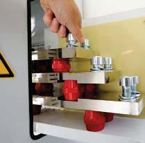
6 Company Profile Design & Manufacture Matag the ability to design & manufacture house generates a large degree of flexibility. The SCHAEFER Client profits from these engeerg skills through an optimised solution tailored to the needs and parameters of the Project. Immediate proximity also generates the free flowg formation path, which is the production and development area, along with the testg and customer support area beg all under the same roof. This enhances the SCHAEFER Teams ability to react to exactg demands with ease. Fruits of this labour are to be seen through the world a variety of fields such as: n n n n n n n n Rail & Automotive Industry Power Generation Plants Oil & Gas Industry Chemical Industry Industrial Automation Military Industry Buildg Security Integrated Airport Solutions Development guideles, arduous selection of dustrial components regardg their load criteria and temperature performance as well as many test procedures durg all steps of production ensure the highest product quality. In addition, Schaefer pursues a full supplier management accordg to ISO 9001 which guarantees permanent improvement of the products especially with the turbulent market of electronic components. On demand, SCHAEFER can also provide additional customer specified tests cooperation with external test laboratories.


7 Innovation made Germany 5 6


8 Company Profile Products & Applications Be they on shore or off shore, stationary or mobile, land, air or mare based. A system component or complete system, environmentally Hazardous area1, corrosive or simply Industrial, there is a SCHAEFER Power Solution to fit the specified parameters. System Design & tegration
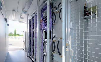


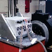
9 7 8 Installation of a 360kW expandable power supply system with a contaer for meral exploration on vessel Contaer ready for shipment On board stallation
 or 200 / 400 / 480V, three phases Input frequency: with PFC")

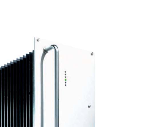
10 Low Power Converters from 100W to 7.5kW, switchmode or / Converters, / Power Supplies & Battery Chargers Input voltage: V Input voltage: 115 / 230V, sgle phase (with or with PFC) or 200 / 400 / 480V, three phases Input frequency: with PFC 47-65Hz, with PFC Hz voltage: 5 /... / 400V current: up to 500A power: 100W - 7.5kW Features Input / isolation Contuous short circuit protection Overvoltage protection with auto restart Operational from 40 to +75 C Industrial grade components Compact and robust design Natural convection (except for series C56xx and C57xx) Specifications Input Voltage range No-load put power Inrush current Hold-up time unit switches off at under- and overvoltage 5-6W typical except for series 4800, 5600/5700 put: limited by thermistor put: 10ms nom. put voltage (for series 4800: 5ms typical) Immunity acc. to EN put voltages Le regulation (±10%) 0.1% Load regulation (10-90%) 0.2% Load transient ( %) 6 % typical Response time to ±1 % 2-3 ms Turn-on rise time Soft-start, 100 ms typical Ripple 1% + 30 mv p-p Overload protection current limited to % of I nom Overvoltage protection OVP switches off module with automatic return to operation Remote sense standard for all series except for B / BP series; up to 10% of U nom for put < 60V, up to 6V for put > 60V General Efficiency Operatg temperature 80-92% typical -20 to +75 C (optional: -40 to +75 C) Load deratg 2.5%/ C above + 55 C Storage temperature -40 to + 85 C (details see page 131) Humidity Temperature coefficient = natural convection = creased air flow recommended = cl. temperature controlled fans up to 95 % RH, non-condensg 0.02 % / C typical Safety / Construction acc. to EN / EN Protection category IP20 acc. to EN 60529, NEMA or others upon request EMI acc. to EN , class A, optionally class B MTBF 40 C acc. to MIL - HDBK - 217E (notice 1) Connectors (details see page 132) H15 acc. to DIN and high current connectors for I > 50 A, or termals / bolts / bars

 Signals via")
")
 Programmg of battery")
 Mechanics /")

11 9 10 Options (details see page 115) Input Inrush current limitg Reverse polarity protection for put Autorangg for 115 / 230 V put Decouplg diode for redundant / parallel operation Active current sharg for parallel operation Remote on / off (hibit) Signals via relay contacts Power ok (put) ok (put) Monitorg of put / put voltage or current via analog signal terface card RS232 or CAN Bus (external) Programmg of put voltage or current via potentiometer analog signal terface card RS232 or CAN Bus (external) Programmg of battery chargers Temperature compensated chargg voltage Automatic / manual selection of chargg characteristic (external) Mechanics / environment: 19 sub-rack for eurocassette, refer to page 121 Wall mount Chassis mount DIN rail mount Increased mechanical strength Tropical protection Extended temperature range to 40 C
12 Low Power Converters from 100W to 7.5kW, switchmode Selector Guide Series Power put put CH / CP / BP W C / B W C / B W S W C / B W C / B W C / B W C / B W C / B W W W W kw kw [V] V V V V V V V V V 1-phase 1-phase with PFC 3-phase C / B W C / B W C / B W C / B kw C / CP / B / BP kw C / B kw C / B kw C 5600 / kw Step-Up Converters 100 W 7.5 kw Further Information Order example Assistance table use: 1 Select the column for put voltage range. 2 Select the row for the appropriate put voltage. 3 The tersection of both results the module required. Input For example: 1 put voltage = 48 2 put voltage = 12 A 3 results a CH 232 module Adj. Range 1 CH 220 CH 221 CH 230 CH 231 CH 240 CH 241 CH 250 CH 251 CH 270 CH CH 222 CH CH 242 CH 252 CH CH CH CH CH CH CH 227 CH 237 CH 247 CH 257 CH CH 228 CH 238 CH 248 CH 258 CH Conversion table Height: 1 U = mm 1 U = 1.75 Width: 1 TE = 5.08 mm 1 TE = = 25.4 mm 19 = 483 mm Weight: 1 kg = 2.2 lbs
13 11 12 Nomal put voltage Package Page [V] 5 V 9 V 12 V 15 V 24 V 28 V 48 V 60 V 110 V 200 V 220 V 400 V Eurocassette for 19 Rack mount Height [U] 19 Plug- module Height [U] Wall mount Chassis mount DIN rail mount 5 / 9 /... / / 9 /... / / 9 /... / / 9 /... / / 9 /... / / 9 /... / / 9 /... / / 9 /... / / 9 /... / Natural convection Fan cooled 5 / 9 /... / / 9 /... / / 12 /... / / 9 /... / / 9 /... / / 15 /... / / 15 /... / / 9 /... / /... / / 6 dependg on module 47 Conversion diagram C F F - 40 C - 20 C 55 C 75 C 85 C C 185 F 167 F 131 F 4 F 40 F
14 Low Power Series CH / CP / BP / Converters 150 W Input Adj. Range CH 220 CH 221 CH 222 CH 223 CH 224 CH 225 CH 229 CH 226 CH 230 CH 231 CH 232 CH 233 CH 234 CH 235 CH 239 CH 236 CH 240 CH 241 CH 242 CH 243 CH 244 CH 245 CH 249 CH 246 CH 250 CH 251 CH 252 CH 253 CH 254 CH 255 CH 259 CH 256 CH 270 CH 271 CH 272 CH 273 CH 274 CH 275 CH 279 CH / Power Supplies 150 W Input V, 1-Phase V ±10 % Adj. Range CP 290 CP 291 CP 292 CP 293 CP 294 CP 295 CP 299 CP Battery Battery Chargers 150 W Input V, 1-Phase V 10 % Nom. Battery Voltage Range BP 291 BP 292 BP 294 BP Series specific formation Input Protection: by ternal fuse Switch-on time: 250ms typical Power factor correction for CP/BP series acc. to EN , class D Response time to ±1 %: 1ms typical Remote sense: standard for CH/ CP series, up to 10% of U nom for put <40V, up to 4V for put >40V Active current sharg for parallel operation Charger control: acc. to IU characteristics ok signal via open collector General EMI: acc. to EN 55022, class B Options The number of options per module is restricted to put, put and mechanics/ environments (see page 10). = natural convection

 approx. 0.")


15 76mm U 165 mm 10TE Standard Eurocassette (pluggable module for 19 sub-rack) approx. 0.7 kg 3U 109mm 138mm 76mm 195mm Optional Chassis mount approx kg 109mm 193.5mm Optional DIN rail mount approx. 1.0 kg
16 Low Power Series C / B / Converters 120 W 150 W 200 W Input ) Adj. Range C 1200 C C 1220 C C 1230 C 1231 C 1240 C 1241 C 1250 C 1251 C 1270 C 1271 C 1280 Z C 1281 Z C 1202 C C 1222 C C 1232 C 1233 C 1242 C 1243 C 1252 C 1253 C 1272 C 1273 C 1282 Z C 1283 Z C 1204 C C 1224 C C 1234 C 1235 C 1244 C 1245 C 1254 C 1255 C 1274 C 1275 C 1284 Z C 1285 Z C 1209 C C 1229 C C 1239 C 1236 C 1249 C 1246 C 1259 C 1256 C 1279 C 1276 C 1289 Z C 1286 Z C 1207 C C 1227 C C 1237 C 1238 C 1247 C 1248 C 1257 C 1258 C 1277 C 1278 C 1287 Z C 1288 Z / Power Supplies 200 W Input V, 1-Phase 115 ± 20 % % 20 % 115 ± 20 % / % 20 % Adj. Range C 1260 C 1261 C 1280 C 1281 C 1290 C C 1262 C 1263 C 1282 C 1283 C 1292 C C 1264 C 1265 C 1284 C 1285 C 1294 C C 1269 C 1266 C 1289 C 1286 C 1299 C C 1267 C 1268 C 1287 C 1288 C 1297 C Battery Battery Chargers 115 ± 20 % % 20 % 200 W Input V, 1-Phase 115 ± 20 % / % 20 % Nom. Battery Voltage Range B 1261 B 1262 B 1264 B 1266 B 1267 B 1268 B 1281 B 1282 B 1284 B 1286 B 1287 B 1288 B 1291 B 1292 B 1294 B 1296 B 1297 B Series specific formation Input Switch-on time: 500ms typical 1) Input supply from PFC also suitable = natural convection


17 65 mm U Standard 10TE 164 mm Eurocassette (pluggable module for 19 sub-rack) approx. 1.7 kg 140 mm 360 mm 260 mm 6U 3U Optional Wall mount approx. 4.7 kg 240 mm 295 mm Optional mm Chassis mount approx. 2.1 kg
18 Low Power Series C / B / Converters 180 W 200 W 250 W Input ) Adj. Range C 500 C 501 C 502 C 503 C 504 C 505 C 509 C 506 C 507 C C 520 C 521 C 522 C 523 C 524 C 525 C 529 C 526 C 527 C C 530 C 531 C 532 C 533 C 534 C 535 C 539 C 536 C 537 C 538 C 540 C 541 C 542 C 543 C 544 C 545 C 549 C 546 C 547 C 548 C 550 C 551 C 552 C 553 C 554 C 555 C 559 C 556 C 557 C 558 C 570 C 571 C 572 C 573 C 574 C 575 C 579 C 576 C 577 C 578 C 580 Z C 581 Z C 582 Z C 583 Z C 584 Z C 585 Z C 589 Z C 586 Z C 587 Z C 588 Z / Power Supplies Input V, 1-Phase 115 ± 20 % % 20 % 250 W Input V, 3-Phase 115 ± 20 % / % 20 % 3x % 20 % Adj. Range C 560 C 561 C 562 C 563 C 564 C 565 C 569 C 566 C 567 C 568 C 580 C 581 C 582 C 583 C 584 C 585 C 589 C 586 C 587 C 588 C 590 C 591 C 592 C 593 C 594 C 595 C 599 C 596 C 597 C 598 C 560 V C 561 V C 562 V C 563 V C 564 V C 565 V C 569 V C 566 V C 567 V C 568 V Battery Battery Chargers Input V, 1-Phase 115 ± 20 % % 20 % 250 W 115 ± 20 % / % 20 % Input V, 3-Phase 3x % 20 % t Nom. Battery Voltage Range B 561 B 562 B 564 B 566 B 567 B 568 B 581 B 582 B 584 B 586 B 587 B 588 B 591 B 592 B 594 B 596 B 597 B 598 B 561 V B 562 V B 564 V B 566 V B 567 V B 568 V Series specific formation Input Switch-on time: 1-2s 1) Input supply from PFC also suitable = natural convection


19 U 21TE 24TE* mm Standard Eurocassette (pluggable module for 19 sub-rack) *) applicable to 5 V put models approx. 1.7 kg 180 mm 140 mm 220 mm Optional Wall mount approx. 3.2 kg 3U 106 mm 135 mm 125 mm 205 mm Optional Chassis mount approx. 2.1 kg 106 mm 125 mm 200 mm Optional DIN rail mount approx kg
20 Low Power Series S / Converters 200 W 300 W 350 W Input ) Adj. Range S 600 S S 620 S S 630 S 631 S 640 S 641 S 650 S 651 S 670 S 671 S 680 Z S 681 Z S 602 S S 622 S S 632 S 633 S 642 S 643 S 652 S 653 S 672 S 673 S 682 Z S 683 Z S 604 S S 624 S S 634 S 635 S 644 S 645 S 654 S 655 S 674 S 675 S 684 Z S 685 Z S 609 S S 629 S S 639 S 636 S 649 S 646 S 659 S 656 S 679 S 676 S 689 Z S 686 Z S 607 S S 627 S S 637 S 638 S 647 S 648 S 657 S 658 S 677 S 678 S 687 Z S 688 Z / Power Supplies Input V, 1-Phase 115 ± 20 % % 20 % 350 W Input V, 3-Phase 115 ± 20 % / % 20 % 3x % 20 % Adj. Range S 660 S 661 S 680 S 681 S 690 S 691 S 660 V S 661 V S 662 S 663 S 682 S 683 S 692 S 693 S 662 V S 663 V S 664 S 665 S 684 S 685 S 694 S 695 S 664 V S 665 V S 669 S 666 S 689 S 686 S 699 S 696 S 669 V S 666 V S 667 S 668 S 687 S 688 S 697 S 698 S 667 V S 668 V Series specific formation Input Switch-on time: 500ms typical 1) Input supply from PFC also suitable = natural convection

 approx. 2.")


21 U 42TE mm Standard Eurocassette (pluggable module for 19 sub-rack) approx. 2.6 kg 167 mm 220 mm 3U 130 mm 170 mm 220 mm Optional Wall mount approx. 3.6 kg mm 171 mm Optional Chassis mount approx. 3.1 kg 130 mm mm 175 mm Optional DIN rail mount approx. 3.0 kg
22 Low Power Series C / B / Converters 250 W 300 W 400 W Input ) Adj. Range C 1300 C C 1320 C C 1330 C 1331 C 1340 C 1341 C 1350 C 1351 C 1370 C 1371 C 1380 Z C 1381 Z C 1302 C C 1322 C C 1332 C 1333 C 1342 C 1343 C 1352 C 1353 C 1372 C 1373 C 1382 Z C 1383 Z C 1304 C C 1324 C C 1334 C 1335 C 1344 C 1345 C 1354 C 1355 C 1374 C 1375 C 1384 Z C 1385 Z C 1309 C C 1329 C C 1339 C 1336 C 1349 C 1346 C 1359 C 1356 C 1379 C 1376 C 1389 Z C 1386 Z C 1307 C C 1327 C C 1337 C 1338 C 1347 C 1348 C 1357 C 1358 C 1377 C 1378 C 1387 Z C 1388 Z / Power Supplies 115 ± 20 % % 20 % 400 W Input V, 1-Phase 115 ± 20 % / % 20 % Adj. Range C 1360 C 1361 C 1362 C 1363 C 1364 C 1365 C 1369 C 1366 C 1367 C 1368 C 1380 C 1381 C 1382 C 1383 C 1384 C 1385 C 1389 C 1386 C 1387 C 1388 C 1390 C 1391 C 1392 C 1393 C 1394 C 1395 C 1399 C 1396 C 1397 C Battery Battery Chargers 400 W Input V, 1-Phase 115 ± 20 % % 20 % 115 ± 20 % / % 20 % Nom. Battery Voltage Range B 1361 B 1362 B 1364 B 1366 B 1367 B 1368 B 1381 B 1382 B 1384 B 1386 B 1387 B 1388 B 1391 B 1392 B 1394 B 1396 B 1397 B Series specific formation Input Switch-on time: 500ms typical 1) Input supply from PFC also suitable = natural convection

23 U Standard 14TE 164 mm Eurocassette (pluggable module for 19 sub-rack) approx. 2.0 kg 140 mm 6U 240 mm 295 mm 360 mm Optional 260 mm Wall mount approx. 5.0 kg 88 mm 200 mm Optional Chassis mount approx. 2.4 kg
24 Low Power Series C / B / Converters 300 W 400 W Input ) Adj. Range C 2520 C 2521 C 2522 C 2523 C 2524 C 2525 C 2529 C 2526 C 2527 C C 2530 C 2531 C 2532 C 2533 C 2534 C 2535 C 2539 C 2536 C 2537 C 2538 C 2540 C 2541 C 2542 C 2543 C 2544 C 2545 C 2549 C 2546 C 2547 C 2548 C 2550 C 2551 C 2552 C 2553 C 2554 C 2555 C 2559 C 2556 C 2557 C 2558 C 2570 C 2571 C 2572 C 2573 C 2574 C 2575 C 2579 C 2576 C 2577 C 2578 C 2580 Z C 2581 Z C 2582 Z C 2583 Z C 2584 Z C 2585 Z C 2589 Z C 2586 Z C 2587 Z C 2588 Z / Power Supplies Input V, 1-Phase 115 ± 20 % % 20 % 400 W Input V, 3-Phase 115 ± 20 % / % 20 % 3x % 20 % Adj. Range C 2560 C 2561 C 2562 C 2563 C 2564 C 2565 C 2569 C 2566 C 2567 C 2568 C 2580 C 2581 C 2582 C 2583 C 2584 C 2585 C 2589 C 2586 C 2587 C 2588 C 2590 C 2591 C 2592 C 2593 C 2594 C 2595 C 2599 C 2596 C 2597 C 2598 C 2560 V C 2561 V C 2562 V C 2563 V C 2564 V C 2565 V C 2569 V C 2566 V C 2567 V C 2568 V Battery Battery Chargers Input V, 1-Phase 115 ± 20 % % 20 % 400 W 115 ± 20 % / % 20 % Input V, 3-Phase 3x % 20 % Nom. Battery Voltage Range B 2561 B 2562 B 2564 B 2566 B 2567 B 2568 B 2581 B 2582 B 2584 B 2586 B 2587 B 2588 B 2591 B 2592 B 2594 B 2596 B 2597 B 2598 B 2561 V B 2562 V B 2564 V B 2566 V B 2567 V B 2568 V Series specific formation Input Switch-on time: 500ms typical 1) Input supply from PFC also suitable = natural convection


25 U 21TE 24TE* 226 mm Standard Eurocassette (pluggable module for 19 sub-rack) *) applicable to 5 V put models approx. 2.5 kg 260 mm 140 mm 3U 106 mm 135 mm 300 mm Optional Wall mount approx. 5.0 kg mm mm Optional Chassis mount approx. 3.0 kg
26 Low Power Series C / B / Converters 300 W 450 W 500 W Input ) Adj. Range C 600 C 601 C 602 C 603 C 604 C 605 C 609 C 606 C 607 C C 620 C 621 C 622 C 623 C 624 C 625 C 629 C 626 C 627 C C 630 C 631 C 632 C 633 C 634 C 635 C 639 C 636 C 637 C 638 C 640 C 641 C 642 C 643 C 644 C 645 C 649 C 646 C 647 C 648 C 650 C 651 C 652 C 653 C 654 C 655 C 659 C 656 C 657 C 658 C 670 C 671 C 672 C 673 C 674 C 675 C 679 C 676 C 677 C 678 C 680 Z C 681 Z C 682 Z C 683 Z C 684 Z C 685 Z C 689 Z C 686 Z C 687 Z C 688 Z / Power Supplies Input V, 1-Phase 115 ± 20 % % 20 % 500 W Input V, 3-Phase 115 ± 20 % / % 20 % 3x % 20 % Adj. Range C 660 C 661 C 662 C 663 C 664 C 665 C 669 C 666 C 667 C 668 C 680 C 681 C 682 C 683 C 684 C 685 C 689 C 686 C 687 C 688 C 690 C 691 C 692 C 693 C 694 C 695 C 699 C 696 C 697 C 698 C 660 V C 661 V C 662 V C 663 V C 664 V C 665 V C 669 V C 666 V C 667 V C 668 V Battery Battery Chargers Input V, 1-Phase 115 ± 20 % % 20 % 500 W 115 ± 20 % / % 20 % Input V, 3-Phase 3x % 20 % Nom. Battery Voltage Range B 661 B 662 B 664 B 666 B 667 B 668 B 681 B 682 B 684 B 686 B 687 B 688 B 691 B 692 B 694 B 696 B 697 B 698 B 661 V B 662 V B 664 V B 666 V B 667 V B 668 V Series specific formation Input Switch-on time: 500ms typical 1) Input supply from PFC also suitable = natural convection


27 U 42TE mm Standard Eurocassette (pluggable module for 19 sub-rack) approx. 3.5 kg 167 mm 220 mm 3U 130 mm 170 mm 220 mm Optional Wall mount approx. 4.5 kg Optional mm 171 mm Chassis mount (available for currents up to 60) approx. 4.0 kg 130 mm mm 175 mm Optional approx. 3.9 kg DIN rail mount (available for currents up to 60)
28 Low Power Series C / B / Converters 400 W 500 W 600 W Input ) Adj. Range C 1500 C 1501 C 1502 C 1503 C 1504 C 1505 C 1509 C 1506 C 1507 C 1507 J C 1508 C 1508 J C 1520 C 1521 C 1522 C 1523 C 1524 C 1525 C 1529 C 1526 C 1527 C 1527 J C 1528 C 1528 J C 1530 C 1531 C 1532 C 1533 C 1534 C 1535 C 1539 C 1536 C 1537 C 1537 J C 1538 C 1538 J C 1540 C 1541 C 1542 C 1543 C 1544 C 1545 C 1549 C 1546 C 1547 C 1547 J C 1548 C 1548 J C 1550 C 1551 C 1552 C 1553 C 1554 C 1555 C 1559 C 1556 C 1557 C 1557 J C 1558 C 1558 J C 1570 C 1571 C 1572 C 1573 C 1574 C 1575 C 1579 C 1576 C 1577 C 1577 J C 1578 C 1578 J C 1580 Z C 1581 Z C 1582 Z C 1583 Z C 1584 Z C 1585 Z C 1589 Z C 1586 Z C 1587 Z C 1587 ZJ C 1588 Z C 1588 ZJ / Power Supplies 600 W Input V, 1-Phase 115 ± 20 % % 20 % Input V, 3-Phase 115 ± 20 % / % 20 % 3x % 20 % Adj. Range C 1560 C 1561 C 1562 C 1563 C 1564 C 1565 C 1569 C 1566 C 1567 C 1567 J C 1568 C 1568 J C 1580 C 1581 C 1582 C 1583 C 1584 C 1585 C 1589 C 1586 C 1587 C 1587 J C 1588 C 1588 J C 1590 C 1591 C 1592 C 1593 C 1594 C 1595 C 1599 C 1596 C 1597 C 1597 J C 1598 C 1598 J C 1560 V C 1561 V C 1562 V C 1563 V C 1564 V C 1565 V C 1569 V C 1566 V C 1567 V C 1567 VJ C 1568 V C 1568 VJ Battery Battery Chargers 600 W Input V, 1-Phase 115 ± 20 % % 20 % 115 ± 20 % / % 20 % Input V, 3-Phase 3x % 20 % Nom. Battery Voltage Range B 1561 B 1562 B 1564 B 1566 B 1567 B 1568 B 1581 B 1582 B 1584 B 1586 B 1587 B 1588 B 1591 B 1592 B 1594 B 1596 B 1597 B 1598 B 1561 V B 1562 V B 1564 V B 1566 V B 1567 V B 1568 V Series specific formation Input Switch-on time: 500ms typical 1) Input supply from PFC also suitable = natural convection
 approx.")
29 U Standard 21TE 24TE* Eurocassette (pluggable module for 19 sub-rack) *) applicable to 5 V put models mm approx. 3.3 kg 260 mm 140 mm 6U 240 mm 295 mm 360 mm Optional Wall mount approx. 6.3 kg 125 mm Optional 200 mm Chassis mount (available for currents up to 60) approx. 3.8 kg
30 Low Power Series C / B / Converters 650 W 800 W Input ) Adj. Range C 2620 C 2621 C 2622 C 2623 C 2624 C 2625 C 2629 C 2626 C 2627 C C 2630 C 2631 C 2632 C 2633 C 2634 C 2635 C 2639 C 2636 C 2637 C 2638 C 2640 C 2641 C 2642 C 2643 C 2644 C 2645 C 2649 C 2646 C 2647 C 2648 C 2650 C 2651 C 2652 C 2653 C 2654 C 2655 C 2659 C 2656 C 2657 C 2658 C 2670 C 2671 C 2672 C 2673 C 2674 C 2675 C 2679 C 2676 C 2677 C 2678 C 2680 Z C 2681 Z C 2682 Z C 2683 Z C 2684 Z C 2685 Z C 2689 Z C 2686 Z C 2687 Z C 2688 Z / Power Supplies Input V, 1-Phase 115 ± 20 % % 20 % 800 W Input V, 3-Phase 115 ± 20 % / % 20 % 3x % 20 % Adj. Range C 2660 C 2661 C 2662 C 2663 C 2664 C 2665 C 2669 C 2666 C 2667 C 2668 C 2680 C 2681 C 2682 C 2683 C 2684 C 2685 C 2689 C 2686 C 2687 C 2688 C 2690 C 2691 C 2692 C 2693 C 2694 C 2695 C 2699 C 2696 C 2697 C 2698 C 2660 V C 2661 V C 2662 V C 2663 V C 2664 V C 2665 V C 2669 V C 2666 V C 2667 V C 2668 V Battery Battery Chargers Input V, 1-Phase 115 ± 20 % % 20 % 800 W 115 ± 20 % / % 20 % Input V, 3-Phase 3x % 20 % Nom. Battery Voltage Range B 2661 B 2662 B 2664 B 2666 B 2667 B 2668 B 2681 B 2682 B 2684 B 2686 B 2687 B 2688 B 2691 B 2692 B 2694 B 2696 B 2697 B 2698 B 2661 V B 2662 V B 2664 V B 2666 V B 2667 V B 2668 V Series specific formation Input Switch-on time: 500ms typical 1) Input supply from PFC also suitable = natural convection = creased air flow recommended


31 3U m 42 6m TE 22 Standard Eurocassette approx. 4.0 kg (pluggable module for 19 sub-rack) 22 m 0m 9m mm m Optional Wall mount approx. 6.0 kg 170 mm 130 mm 3U mm m 0m 26 Optional Chassis mount (available for currents up to 60) approx. 4.6 kg
32 Low Power Series C / B Battery / Converters C 3520 C 3521 C 3522 C 3523 C 3524 C 3525 C 3529 C 3526 C 3527 C 3527 J C 3528 C 3528 J 700 W 850 W Input / Power Supplies Battery Chargers Input V, 1-Phase 115 ± 20 % / 115 ± 20 % % 20 % % 20 % ) 850 W Input V, 3-Phase ) 3x % 20 % 3x % 20 % 3x % 15 % Adj. Range C 3560 C 3561 C 3562 C 3563 C 3564 C 3565 C 3569 C 3566 C 3567 C 3567 J C 3568 C 3568 J C 3580 C 3581 C 3582 C 3583 C 3584 C 3585 C 3589 C 3586 C 3587 C 3587 J C 3588 C 3588 J C 3590 C 3591 C 3592 C 3593 C 3594 C 3595 C 3599 C 3596 C 3597 C 3597 J C 3598 C 3598 J C 3560 V C 3561 V C 3562 V C 3563 V C 3564 V C 3565 V C 3569 V C 3566 V C 3567 V C 3567 VJ C 3568 V C 3568 VJ C 3580 V C 3581 V C 3582 V C 3583 V C 3584 V C 3585 V C 3589 V C 3586 V C 3587 V C 3587 VJ C 3588 V C 3588 VJ C 3590 V C 3591 V C 3592 V C 3593 V C 3594 V C 3595 V C 3599 V C 3596 V C 3597 V C 3597 VJ C 3598 V C 3598 VJ C 3521 C 3523 C 3525 C 3526 C 3527 J C 3528 J C 3530 C 3531 C 3532 C 3533 C 3534 C 3535 C 3539 C 3536 C 3537 C 3537 J C 3538 C 3538 J C 3540 C 3541 C 3542 C 3543 C 3544 C 3545 C 3549 C 3546 C 3547 C 3547 J C 3548 C 3548 J C 3550 C 3551 C 3552 C 3553 C 3554 C 3555 C 3559 C 3556 C 3557 C 3557 J C 3558 C 3558 J C 3570 C 3571 C 3572 C 3573 C 3574 C 3575 C 3579 C 3576 C 3577 C 3577 J C 3578 C 3578 J C 3580 Z C 3581 Z C 3582 Z C 3583 Z C 3584 Z C 3585 Z C 3589 Z C 3586 Z C 3587 Z C 3587 ZJ C 3588 Z C 3588 ZJ C 3570 G C 3571 G C 3572 G C 3573 G C 3574 G C 3575 G C 3579 G C 3576 G C 3577 G C 3577 GJ C 3578 G C 3578 GJ Adj. Range 850 W Input V, 1-Phase Input V, 3-Phase 115 ± 20 % % ± 20 % / Nom. 20 % % 3x % 20 % 3x % 20 % 3x % 15 % Battery 20 % Voltage Range B 3561 B 3581 B 3591 B 3561 V B 3581 V B 3591 V B 3562 B 3582 B 3592 B 3562 V B 3582 V B 3592 V B 3564 B 3584 B 3594 B 3564 V B 3584 V B 3594 V B 3566 B 3586 B 3596 B 3566 V B 3586 V B 3596 V B 3567 B 3587 B 3597 B 3567 V B 3587 V B 3597 V B 3568 B 3588 B 3598 B 3568 V B 3588 V B 3598 V Series specific formation Input General General Switch-on time: 1-2s Thermal Thermal shutdown shutdown with auto with restart auto restart 1) 2) Input supply from PFC also suitable Suited for wall-mount, alternatives upon request = natural convection = creased air flow recommended
33 U 21TE 24TE* 226 mm Standard Eurocassette (pluggable module for 19 sub-rack) *) applicable to 5 V put models approx. 5.0 kg 260 mm 140 mm 6U 240 mm 295 mm 360 mm Optional Wall mount approx. 8.0 kg Optional 125 mm 260 mm Chassis mount (available for currents up to 60) approx. 5.5 kg
34 Low Power Series C / B / Converters 1000 W 1250 W Input ) ) Adj. Range Battery C 3720 C 3721 C 3722 C 3723 C 3724 C 3725 C 3729 C 3726 C 3727 C 3727 J C 3728 C 3728 J C 3730 C 3731 C 3732 C 3733 C 3734 C 3735 C 3739 C 3736 C 3737 C 3737 J C 3738 C 3738 J C 3740 C 3741 C 3742 C 3743 C 3744 C 3745 C 3749 C 3746 C 3747 C 3747 J C 3748 C 3748 J C 3750 C 3751 C 3752 C 3753 C 3754 C 3755 C 3759 C 3756 C 3757 C 3757 J C 3758 C 3758 J C 3770 C 3771 C 3772 C 3773 C 3774 C 3775 C 3779 C 3776 C 3777 C 3777 J C 3778 C 3778 J C 3780 Z C 3781 Z C 3782 Z C 3783 Z C 3784 Z C 3785 Z C 3789 Z C 3786 Z C 3787 Z C 3787 ZJ C 3788 Z C 3788 ZJ C 3770 G C 3771 G C 3772 G C 3773 G C 3774 G C 3775 G C 3779 G C 3776 G C 3777 G C 3777 GJ C 3778 G C 3778 GJ / Power Supplies Battery Chargers Input V, 1-Phase 115 ± 20 % / 115 ± 20 % % 20 % % 20 % 1250 W Input V, 3-Phase 3x % 20 % 3x % 20 % 3x % 15 % Adj. Range C 3760 C 3761 C 3762 C 3763 C 3764 C 3765 C 3769 C 3766 C 3767 C 3767 J C 3768 C 3768 J C 3780 C 3781 C 3782 C 3783 C 3784 C 3785 C 3789 C 3786 C 3787 C 3787 J C 3788 C 3788 J C 3790 C 3791 C 3792 C 3793 C 3794 C 3795 C 3799 C 3796 C 3797 C 3797 J C 3798 C 3798 J C 3760 V C 3761 V C 3762 V C 3763 V C 3764 V C 3765 V C 3769 V C 3766 V C 3767 V C 3767 VJ C 3768 V C 3768 VJ C 3780 V C 3781 V C 3782 V C 3783 V C 3784 V C 3785 V C 3789 V C 3786 V C 3787 V C 3787 VJ C 3788 V C 3788 VJ C 3790 V C 3791 V C 3792 V C 3793 V C 3794 V C 3795 V C 3799 V C 3796 V C 3797 V C 3797 VJ C 3798 V C 3798 VJ W Input V, 1-Phase Input V, 3-Phase 115 ± 20 % % ± 20 % / Nom. 20 % % 3x % 20 % 3x % 20 % 3x % 15 % Battery 20 % Voltage Range B 3761 B 3781 B 3791 B 3761 V B 3781 V B 3791 V B 3762 B 3782 B 3792 B 3762 V B 3782 V B 3792 V B 3764 B 3784 B 3794 B 3764 V B 3784 V B 3794 V B 3766 B 3786 B 3796 B 3766 V B 3786 V B 3796 V B 3767 B 3787 B 3797 B 3767 V B 3787 V B 3797 V B 3768 B 3788 B 3798 B 3768 V B 3788 V B 3798 V Series specific formation Input General General Switch-on time: 1-2s Thermal Thermal shutdown shutdown with auto with restart auto restart 1) 2) Input supply from PFC also suitable Suited for wall-mount, alternatives upon request = natural convection = creased air flow recommended


35 6U m 6m TE Standard Eurocassette approx. 6.5 kg (pluggable module for 19 sub-rack) 14 0m m mm mm 2 Optional approx. 9.5 kg 295 mm 241 mm 6U Wall mount 15 5m m m 2m 26 Optional Chassis mount (available for currents up to 60) approx. 7.5 kg
36 Low Power Series C / B / Converters 900 W 1200 W 1600 W Input ) ) ) Adj. Range C 4501 C C 4521 C C 4531 C 4532 C 4541 C 4542 C 4551 C 4552 C 4571 C 4572 C 4581 Z C 4582 Z C 4571 G C 4572 G C 4571 K C 4572 K C 4503 C C 4523 C C 4533 C 4534 C 4543 C 4544 C 4553 C 4554 C 4573 C 4574 C 4583 Z C 4584 Z C 4573 G C 4574 G C 4573 K C 4574 K C 4505 C C 4525 C C 4535 C 4539 C 4545 C 4549 C 4555 C 4559 C 4575 C 4579 C 4585 Z C 4589 Z C 4575 G C 4579 G C 4575 K C 4579 K C 4506 C C 4526 C C 4536 C 4537 C 4546 C 4547 C 4556 C 4557 C 4576 C 4577 C 4586 Z C 4587 Z C 4576 G C 4577 G C 4576 K C 4577 K C 4507 J C C 4527 J C C 4537 J C 4538 C 4547 J C 4548 C 4557 J C 4558 C 4577 J C 4578 C 4587 ZJ C 4588 Z C 4577 GJ C 4578 G C 4577 KJ C 4578 K C 4508 J 2.2 C 4528 J 3 C 4538 J C 4548 J C 4558 J C 4578 J C 4588 ZJ C 4578 GJ C 4578 KJ / Power Supplies Input V, 1-Phase 115 ± 20 % / 115 ± 20 % % 20 % % 20 % 1600 W Input V, 3-Phase 3x % 20 % 3x % 20 % 3x % 15 % Adj. Range C 4561 C 4562 C 4563 C 4564 C 4565 C 4569 C 4566 C 4567 C 4567 J C 4568 C 4568 J C 4581 C 4582 C 4583 C 4584 C 4585 C 4589 C 4586 C 4587 C 4587 J C 4588 C 4588 J C 4591 C 4592 C 4593 C 4594 C 4595 C 4599 C 4596 C 4597 C 4597 J C 4598 C 4598 J C 4561 V C 4562 V C 4563 V C 4564 V C 4565 V C 4569 V C 4566 V C 4567 V C 4567 VJ C 4568 V C 4568 VJ C 4581 V C 4582 V C 4583 V C 4584 V C 4585 V C 4589 V C 4586 V C 4587 V C 4587 VJ C 4588 V C 4588 VJ C 4591 V C 4592 V C 4593 V C 4594 V C 4595 V C 4599 V C 4596 V C 4597 V C 4597 VJ C 4598 V C 4598 VJ Battery Battery Chargers 1600 W Input V, 1-Phase Input V, 3-Phase 115 ± 20 % % ± 20 % / Nom. 20 % % 3x % 20 % 3x % 20 % 3x % 15 % Battery 20 % Voltage Range B 4561 B 4581 B 4591 B 4561 V B 4581 V B 4591 V B 4562 B 4582 B 4592 B 4562 V B 4582 V B 4592 V B 4564 B 4584 B 4594 B 4564 V B 4584 V B 4594 V B 4566 B 4586 B 4596 B 4566 V B 4586 V B 4596 V B 4567 B 4587 B 4597 B 4567 V B 4587 V B 4597 V B 4568 B 4588 B 4598 B 4568 V B 4588 V B 4598 V Series specific formation Input Switch-on time: 1-2s 1) Input supply from PFC also suitable General Thermal shutdown with auto restart 2) Suited for wall-mount, alternatives upon request = creased air flow recommended
 approx. 6.")

37 U 306 mm Standard 21TE Eurocassette (pluggable module for 19 sub-rack) approx. 6.5 kg 140 mm 340 mmm 240 mm 295 mm 360 mm 6U Optional Wall mount approx kg Optional 125 mm 340 mm Chassis mount (available for currents up to 60) approx. 7.5 kg
38 Low Power Series C / B / Converters 1400 W 1700 W Input ) ) ) Adj. Range Battery C 3620 C 3621 C 3622 C 3623 C 3624 C 3625 C 3629 C 3626 C 3627 C 3627 J C 3628 C 3628 J 180 2) C 3630 C 3631 C 3632 C 3633 C 3634 C 3635 C 3639 C 3636 C 3637 C 3637 J C 3638 C 3638 J C 3640 C 3641 C 3642 C 3643 C 3644 C 3645 C 3649 C 3646 C 3647 C 3647 J C 3648 C 3648 J C 3650 C 3651 C 3652 C 3653 C 3654 C 3655 C 3659 C 3656 C 3657 C 3657 J C 3658 C 3658 J C 3670 C 3671 C 3672 C 3673 C 3674 C 3675 C 3679 C 3676 C 3677 C 3677 J C 3678 C 3678 J C 3680 Z C 3681 Z C 3682 Z C 3683 Z C 3684 Z C 3685 Z C 3689 Z C 3686 Z C 3687 Z C 3687 ZJ C 3688 Z C 3688 ZJ C 3670 G C 3671 G C 3672 G C 3673 G C 3674 G C 3675 G C 3679 G C 3676 G C 3677 G C 3677 GJ C 3678 G C 3678 GJ C 3670 K C 3671 K C 3672 K C 3673 K C 3674 K C 3675 K C 3679 K C 3676 K C 3677 K C 3677 KJ C 3678 K C 3678 KJ 200 2) / Power Supplies Battery Chargers Input V, 1-Phase 115 ± 20 % / 115 ± 20 % % 20 % % 20 % 1700 W Input V, 3-Phase 3x % 20 % 3x % 20 % 3x % 15 % Adj. Range C 3660 C 3661 C 3662 C 3663 C 3664 C 3665 C 3669 C 3666 C 3667 C 3667 J C 3668 C 3668 J C 3680 C 3681 C 3682 C 3683 C 3684 C 3685 C 3689 C 3686 C 3687 C 3687 J C 3688 C 3688 J C 3690 C 3691 C 3692 C 3693 C 3694 C 3695 C 3699 C 3696 C 3697 C 3697 J C 3698 C 3698 J C 3660 V C 3661 V C 3662 V C 3663 V C 3664 V C 3665 V C 3669 V C 3666 V C 3667 V C 3667 VJ C 3668 V C 3668 VJ C 3680 V C 3681 V C 3682 V C 3683 V C 3684 V C 3685 V C 3689 V C 3686 V C 3687 V C 3687 VJ C 3688 V C 3688 VJ C 3690 V C 3691 V C 3692 V C 3693 V C 3694 V C 3695 V C 3699 V C 3696 V C 3697 V C 3697 VJ C 3698 V C 3698 VJ 200 2) W Input V, 1-Phase Input V, 3-Phase 115 ± 20 % % ± 20 % / Nom. 20 % % 3x % 20 % 3x % 20 % 3x % 15 % Battery 20 % Voltage Range B 3661 B 3681 B 3691 B 3661 V B 3681 V B 3691 V B 3662 B 3682 B 3692 B 3662 V B 3682 V B 3692 V B 3664 B 3684 B 3694 B 3664 V B 3684 V B 3694 V B 3666 B 3686 B 3696 B 3666 V B 3686 V B 3696 V B 3667 B 3687 B 3697 B 3667 V B 3687 V B 3697 V B 3668 B 3688 B 3698 B 3668 V B 3688 V B 3698 V Series specific formation Input Switch-on time: 1-2s 1) Input supply from PFC also suitable General Thermal shutdown with auto restart 2) Suited for wall-mount, alternatives upon request = natural convection = creased air flow recommended


39 U 42TE 226 mm Standard Eurocassette (pluggable module for 19 sub-rack) approx kg 229 mm 220 mm 360 mm 6U Optional Wall mount approx kg
40 Low Power Series C / CP / B / BP / Converters 1200 W 1700 W 2500 W 2500 W Input ) ) ) Adj. Range C 4700 C 4701 C 4702 C 4703 C 4704 C 4705 C 4709 C 4706 C 4707 C 4707 J C 4708 C 4708 J C 4720 C 4721 C 4722 C 4723 C 4724 C 4725 C 4729 C 4726 C 4727 C 4727 J C 4728 C 4728 J 160 2) C 4730 C 4731 C 4732 C 4733 C 4734 C 4735 C 4739 C 4736 C 4737 C 4737 J C 4738 C 4738 J C 4740 C 4741 C 4742 C 4743 C 4744 C 4745 C 4749 C 4746 C 4747 C 4747 J C 4748 C 4748 J 180 2) C 4750 C 4751 C 4752 C 4753 C 4754 C 4755 C 4759 C 4756 C 4757 C 4757 J C 4758 C 4758 J C 4770 C 4771 C 4772 C 4773 C 4774 C 4775 C 4779 C 4776 C 4777 C 4777 J C 4778 C 4778 J C 4780 Z C 4781 Z C 4782 Z C 4783 Z C 4784 Z C 4785 Z C 4789 Z C 4786 Z C 4787 Z C 4787 ZJ C 4788 Z C 4788 ZJ C 4770 G C 4771 G C 4772 G C 4773 G C 4774 G C 4775 G C 4779 G C 4776 G C 4777 G C 4777 GJ C 4778 G C 4778 GJ C 4770 K C 4771 K C 4772 K C 4773 K C 4774 K C 4775 K C 4779 K C 4776 K C 4777 K C 4777 KJ C 4778 K C 4778 KJ 180 2) Battery / Power Supplies ± 10 % with PFC Battery Chargers 1700 W 2500 W Input V, 1-Phase Input V, 3-Phase ± 20 % % ± 20 % / 20 % % 3x % 20 % 3x % 20 % 3x % 20 % 15 % Adj. Range CP 4790 CP 4791 CP 4792 CP 4793 CP 4794 CP 4795 CP 4799 CP 4796 CP 4797 CP 4797 J CP 4798 CP 4798 J 180 2) C 4760 C 4761 C 4762 C 4763 C 4764 C 4765 C 4769 C 4766 C 4767 C 4767 J C 4768 C 4768 J C 4780 C 4781 C 4782 C 4783 C 4784 C 4785 C 4789 C 4786 C 4787 C 4787 J C 4788 C 4788 J C 4790 C 4791 C 4792 C 4793 C 4794 C 4795 C 4799 C 4796 C 4797 C 4797 J C 4798 C 4798 J C 4760 V C 4761 V C 4762 V C 4763 V C 4764 V C 4765 V C 4769 V C 4766 V C 4767 V C 4767 VJ C 4768 V C 4768 VJ C 4780 V C 4781 V C 4782 V C 4783 V C 4784 V C 4785 V C 4789 V C 4786 V C 4787 V C 4787 VJ C 4788 V C 4788 VJ C 4790 V C 4791 V C 4792 V C 4793 V C 4794 V C 4795 V C 4799 V C 4796 V C 4797 V C 4797 VJ C 4798 V C 4798 VJ 180 2) W 2500 W Input V, 1-Phase Input V, 3-Phase ± 10 % 115 ± 20 % % ± 20 % / Nom. 20 % with PFC % 3x % 20 % 3x % 20 % 3x % 15 % Battery 20 % Voltage Range BP B 4761 B 4781 B 4791 B 4761 V B 4781 V B 4791 V BP B 4762 B 4782 B 4792 B 4762 V B 4782 V B 4792 V BP B 4764 B 4784 B 4794 B 4764 V B 4784 V B 4794 V BP B 4766 B 4786 B 4796 B 4766 V B 4786 V B 4796 V BP B 4767 B 4787 B 4797 B 4767 V B 4787 V B 4797 V BP B 4768 B 4788 B 4798 B 4768 V B 4788 V B 4798 V Series specific formation Input Switch-on time: 1-2s Power factor correction for CP/ BP series, acc. to EN , class D 1) Input supply from external PFC also suitable General Thermal shutdown with auto restart 2) Suited for wall-mount, alternatives upon request = creased air flow recommended
 approx.")


41 U 28TE 306 mm Standard Eurocassette (pluggable module for 19 sub-rack) approx. 9.0 kg 140 mm 345 mm 240 mm 295 mm 360 mm 6U Optional Wall mount approx kg 155 mm 340 mm Optional Chassis mount approx kg (available for currents up to 60)
42 Low Power Series C / B / Converters 2000 W 2500 W Input ) ) ) Adj. Range C 3822 C 3823 C 3824 C 3825 C 3829 C 3826 C 3827 C 3827 J C 3828 C 3828 J C 3832 C 3833 C 3834 C 3835 C 3839 C 3836 C 3837 C 3837 J C 3838 C 3838 J C 3842 C 3843 C 3844 C 3845 C 3849 C 3846 C 3847 C 3847 J C 3848 C 3848 J C 3852 C 3853 C 3854 C 3855 C 3859 C 3856 C 3857 C 3857 J C 3858 C 3858 J C 3872 C 3873 C 3874 C 3875 C 3879 C 3876 C 3877 C 3877 J C 3878 C 3878 J C 3882 Z C 3883 Z C 3884 Z C 3885 Z C 3889 Z C 3886 Z C 3887 Z C 3887 ZJ C 3888 Z C 3888 ZJ C 3872 G C 3873 G C 3874 G C 3875 G C 3879 G C 3876 G C 3877 G C 3877 GJ C 3878 G C 3878 GJ C 3872 K C 3873 K C 3874 K C 3875 K C 3879 K C 3876 K C 3877 K C 3877 KJ C 3878 K C 3878 KJ 160 2) / Power Supplies Input V, 1-Phase 115 ± 20 % / 115 ± 20 % % 20 % % 20 % 2500 W Input V, 3-Phase 3x % 20 % 3x % 20 % 3x % 15 % Adj. Range C 3862 C 3863 C 3864 C 3865 C 3869 C 3866 C 3867 C 3867 J C 3868 C 3868 J C 3882 C 3883 C 3884 C 3885 C 3889 C 3886 C 3887 C 3887 J C 3888 C 3888 J C 3892 C 3893 C 3894 C 3895 C 3899 C 3896 C 3897 C 3897 J C 3898 C 3898 J C 3862 V C 3863 V C 3864 V C 3865 V C 3869 V C 3866 V C 3867 V C 3867 VJ C 3868 V C 3868 VJ C 3882 V C 3883 V C 3884 V C 3885 V C 3889 V C 3886 V C 3887 V C 3887 VJ C 3888 V C 3888 VJ C 3892 V C 3893 V C 3894 V C 3895 V C 3899 V C 3896 V C 3897 V C 3897 VJ C 3898 V C 3898 VJ 160 2) Battery Battery Chargers 2500 W Input V, 1-Phase Input V, 3-Phase 115 ± 20 % % ± 20 % / Nom. 20 % % 3x % 20 % 3x % 20 % 3x % 15 % Battery 20 % Voltage Range B 3861 B 3881 B 3891 B 3861 V B 3881 V B 3891 V B 3862 B 3882 B 3892 B 3862 V B 3882 V B 3892 V B 3864 B 3884 B 3894 B 3864 V B 3884 V B 3894 V B 3866 B 3886 B 3896 B 3866 V B 3886 V B 3896 V B 3867 B 3887 B 3897 B 3867 V B 3887 V B 3897 V B 3868 B 3888 B 3898 B 3868 V B 3888 V B 3898 V Series specific formation Input Switch-on time: 1-2s 1) Input supply from PFC also suitable General Thermal shutdown with auto restart 2) Suited for wall-mount, alternatives upon request = natural convection = creased air flow recommended


 approx.")


43 mm 280/320* mm 360/450* mm 6U 56TE 226 mm Standard Eurocassette (pluggable module for 19 sub-rack) approx kg Optional 6U Wall mount approx. 16 kg/ *) 19 kg *) applicable to models >= 150 A put current
44 Low Power Series C / B / Converters ZVS topology 2.5 kw 3.5 kw 5 kw 5 kw ) ) Input ) ) ) Adj. Range C 4802 C 4803 C 4804 C 4805 C 4809 C 4806 C 4807 C 4807 J C 4808 C 4808 J C 4822 C 4823 C 4824 C 4825 C 4829 C 4826 C 4827 C 4827 J C 4828 C 4828 J C 4832 C 4833 C 4834 C 4835 C 4839 C 4836 C 4837 C 4837 J C 4838 C 4838 J C 4842 C 4843 C 4844 C 4845 C 4849 C 4846 C 4847 C 4847 J C 4848 C 4848 J 240 2) 200 2) C 4852 C 4853 C 4854 C 4855 C 4859 C 4856 C 4857 C 4857 J C 4858 C 4858 J C 4872 C 4873 C 4874 C 4875 C 4879 C 4876 C 4877 C 4877 J C 4878 C 4878 J C 4882 Z C 4883 Z C 4884 Z C 4885 Z C 4889 Z C 4886 Z C 4887 Z C 4887 ZJ C 4888 Z C 4888 ZJ C 4872 G C 4873 G C 4874 G C 4875 G C 4879 G C 4876 G C 4877 G C 4877 GJ C 4878 G C 4878 GJ C 4872 K C 4873 K C 4874 K C 4875 K C 4879 K C 4876 K C 4877 K C 4877 KJ C 4878 K C 4878 KJ 260 2) 220 2) 160 2) / Power Supplies ZVS topology 4 kw 5 kw Input V, 1-Phase Input V, 3-Phase 115 2) + 15 % 230 ± 20 % 20 % 3x % 20 % 3x % 20 % 3x % 15 % Adj. Range C C 4882 C 4862 V C 4882 V C 4892 V 260 2) C C 4883 C 4863 V C 4883 V C 4893 V 220 2) C C 4884 C 4864 V C 4884 V C 4894 V 160 2) C C 4885 C 4865 V C 4885 V C 4895 V C C 4889 C 4869 V C 4889 V C 4899 V C C 4886 C 4866 V C 4886 V C 4896 V C C 4887 C 4867 V C 4887 V C 4897 V C 4867 J 16 C 4887 J C 4867 VJ C 4887 VJ C 4897 VJ C C 4888 C 4868 V C 4888 V C 4898 V C 4868 J 8 C 4888 J C 4868 VJ C 4888 VJ C 4898 VJ Battery Battery Chargers ZVS topology 4 kw 5 kw Input V, 1-Phase Input V, 3-Phase 115 2) Nom % 230 ± 20 % 20 % 3x % 20 % 3x % 20 % 3x % 15 % Battery Voltage Range B B 4881 B 4861 V B 4881 V B 4891 V 220 2) B B 4882 B 4862 V B 4882 V B 4892 V B B 4884 B 4864 V B 4884 V B 4894 V B B 4886 B 4866 V B 4886 V B 4896 V B B 4887 B 4867 V B 4887 V B 4897 V B B 4888 B 4868 V B 4888 V B 4898 V Series specific formation Input No-load put power: 15W typical Switch-on time: 1-2s Inrush current: 230V and 3-phase put: limited by thermistor Hold-up time for put: 5ms nomal put voltage Response time to ±1 %: 5-10ms Turn-on rise time: Soft-start, ms typical OVP with restart for ZVS General Thermal shutdown with auto restart Option rco for ZVS-modules available (see p.118) 1) Input supply from PFC also suitable 2) Suited for wall-mount, alternatives upon request = creased air flow recommended


 22")

45 U 56TE 306 mm Standard Eurocassette (pluggable module for 19 sub-rack) 309 mm 280/320* mm 360/450* mm Optional 6U Wall mount approx. 19 kg/ *) 22 kg *) applicable to models >= 150 A put or put current
46 Low Power Series C 5600 / / Converters series C kw 3.5 kw 5 kw Input Adj. Range C 5600 C 5601 C 5602 C 5603 C 5604 C 5605 C 5609 C 5606 C 5607 C 5607 J C 5608 C 5608 J C 5620 C 5621 C 5622 C 5623 C 5624 C 5625 C 5629 C 5626 C 5627 C 5627 J C 5628 C 5628 J C 5630 C 5631 C 5632 C 5633 C 5634 C 5635 C 5639 C 5636 C 5637 C 5637 J C 5638 C 5638 J C 5640 C 5641 C 5642 C 5643 C 5644 C 5645 C 5649 C 5646 C 5647 C 5647 J C 5648 C 5648 J Series C 5600 and C 4800 are electrically identical up to 80 put. / Converters series C kw 5.1 kw 7.5 kw Input Adj. Range C 5700 C 5701 C 5702 C 5703 C 5704 C 5705 C 5709 C 5706 C 5707 C 5707 J C 5708 C 5708 J C 5720 C 5721 C 5722 C 5723 C 5724 C 5725 C 5729 C 5726 C 5727 C 5727 J C 5728 C 5728 J C 5730 C 5731 C 5732 C 5733 C 5734 C 5735 C 5739 C 5736 C 5737 C 5737 J C 5738 C 5738 J C 5740 C 5741 C 5742 C 5743 C 5744 C 5745 C 5749 C 5746 C 5747 C 5747 J C 5748 C 5748 J Series specific formation Input No-load put power: 15-20W Switch-on time: 1-2s Manual adjustment of put voltage only via external potentiometer General Thermal shutdown with auto restart MTBF: approx. 40 C acc. to MIL - HDBK - 217E (notice 1) = cl. temperature controlled fans

 applicable to models >= 150 A put current series C 5700 6U Standard")
 applicable to models >= 150 A put series C 5700 approx.")
47 45 46 series C U Standard 19" approx. 360 mm 19 Plug- module approx kg series C mm 500 mm 400/600* mm Optional 6U Wall mount approx kg *) applicable to models >= 150 A put current series C U Standard 19" approx. 360/460* mm 19 Plug- module approx kg *) applicable to models >= 150 A put series C 5700 approx. 450 mm 500 mm 400/600* mm Optional Wall mount approx kg *) applicable to models >= 150 A put current

48 Low Power Series E Step-up converters The step-up converters are very similar to the / converters of series C, except that the step-up converters sense the voltage across the load which is the total of the battery voltage and the voltage added by the step-up converter. The step-up converter can not reduce the voltage beg applied to its put. Therefore, the load should be specified for the maximum battery voltage. For put voltage stabilization The put voltage of an e.g. battery charger with parallel connected battery varies substantially with the chargg condition of the battery. For many applications, however, the load circuit requires a better stabilized voltage. Frequently used methods for reducg the voltage variation are e.g. voltage droppg diodes. A more economical solution is given by switch mode step-up converters. These are / converters supplied from the battery with the put connected series to the battery. Due to the circuit configuration, the put of a step-up converter is not isolated from the put supply (battery). Circuit diagrams Step-up converter with common positive le Step-up converter with common negative le standard version The followg circuit diagram shows a step-up converter which can be grounded on the positive side. The voltage will be added at the negative side and the positive le is common for put and put. battery charger = + - step-up converter = + = - load optional version The followg circuit diagram shows a step-up converter which can be grounded on the negative side. The voltage will be added at the positive side and the negative le is common for put and put. battery charger + - step-up converter + - (long) cable to load sense leads load sense leads Parallel operation of step-up converters Individual load supply For more power or redundancy step-up converters may be connected parallel with active current sharg, dividually protected by fuses at the put and decouplg diodes or fuses at the put. Such systems have already been realized for 2,000. battery charger = + - = step-up converters = current sharg signal = = sense leads load For applications that require dividually stabilized voltages across the loads, the step-converters will be connected as shown the followg diagram and may be of different power ratgs. battery charger = + - step-up converters = = = sense leads = sense leads loads


49 47 48 Operation diagram Durg normal operation no voltage needs to be added and the converter runs with a mimum of power losses. The voltage at the load is slightly reduced as the current flows through the bypass diode. The bypass diode also allows for replacement of the step-up converter and should therefore be stalled externally. Durg battery discharge the converter adds the voltage that is needed to mata the required put voltage level. The maximum voltage to be added is normally less than 20 % of the total voltage. Therefore, the step-up converter needs to be designed for 20 % of the throughpower, only. voltage battery voltage normal operation, no voltage added voltage at load voltage added by step-up converter discharge of battery Example: Input: (battery) : 0 10 (step-up voltage) put voltage regulated to 50 V durg discharge of battery time Create your step-up converter Each / converter can be modified to be a step-up converter: calculate the put power of the step-up converter: max. voltage to be added x max. load current choose the suitable C series re-name the model as E C 3720 C 3721 C 3726 C 3727 C 3727 J C 3728 C 3728 J 1000 W 1250 W Input ) ) Step-up Converters Adj. C 3720 C 3726 C 3727 J C 3728 J 120 2) C 3730 C 3731 C 3736 C 3737 C 3737 J C 3738 C 3738 J C 3740 C 3741 C 3746 C 3747 C 3747 J C 3748 C 3748 J C 3750 C 3751 C 3756 C 3757 C 3757 J C 3758 C 3758 J C 3770 C 3771 C 3776 C 3777 C 3777 J C 3778 C 3778 J C 3780 Z C 3781 Z C 3786 Z C 3787 Z C 3787 ZJ C 3788 Z C 3788 ZJ C 3770 G C 3771 G C 3776 G C 3777 G C 3777 GJ C 3778 G C 3778 GJ 150 2) Example: 1000 W 1250 W Range Input (battery voltage) ) ) E 3720 E 3721 E 3726 E 3727 E 3727 J E 3728 E 3728 J 120 2) E 3730 E 3731 E 3736 E 3737 E 3737 J E 3738 E 3738 J E 3740 E 3741 E 3746 E 3747 E 3747 J E 3748 E 3748 J E 3750 E 3751 E 3756 E 3757 E 3757 J E 3758 E 3758 J E 3770 E 3771 E 3776 E 3777 E 3777 J E 3778 E 3778 J E 3780 Z E 3781 Z E 3786 Z E 3787 Z E 3787 ZJ E 3788 Z E 3788 ZJ E 3770 G E 3771 G E 3776 G E 3777 G E 3777 GJ E 3778 G E 3778 GJ 150 2) Voltage at load regulated to dependg on put voltage Step-up voltage

50 High Power Converters from 5 to 40kW, switchmode or / Converters, / Power Supplies & Battery Chargers Input voltage: from V Input voltage: 115 / 230V, sgle phase or 200 / 400 / 480V, three phases Input frequency: Hz voltage: 5 /... / 800V current: up to 800A power: 5-40kW Features Input / isolation Contuous short circuit protection Overvoltage protection Thermal shutdown with auto-restart Operational from 40 to +75 C Industrial grade components High efficiency through ZVS topology High power density Compact and robust design Fan or liquid cooled Specifications Input Voltage range No-load put power Switch-on time Inrush current narrowg of put voltage range optimizes the efficiency (pls. specify); unit switches off at under- and overvoltage 30W typical <1s typical 3-phase put: limited by thermistor (except for series 55xx, 64xx, 66xx, 67xx & CW/BW56xx) Immunity acc. to EN put voltages power from 5 to 40kW Le regulation (±10%) 0.1% Load regulation (10-90%) 0.2% Load transient ( %) 6 % typical Response time to ±1 % 10 ms typical Turn-on rise time Soft-start, 300 ms typical Ripple 1% + 30 mv p-p Overload protection current limited to % of I nom Overvoltage protection OVP switches off module with automatic return to operation; after 5 seconds, the unit will rema latched off Remote sense standard for all series up to 150 V put, except for battery chargers; up to 10 % of U nom for put < 60, up to 6 V for put > 60 General Efficiency 80-95% typical Operatg temperature -20 to +75 C optional: -40 to +75 C Load deratg 2.5%/ C above + 55 C Storage temperature -40 to + 85 C (details see page 131) Humidity Temperature coefficient = fan cooled = liquid cooled up to 95 % RH, non-condensg 0.02 % / C typical Safety / Construction acc. to EN / EN Protection category (built- module) IP20 acc. to EN 60529, NEMA or others upon request EMI acc. to EN , class A, optionally class B MTBF approx. 40 C acc. to MIL - HDBK - 217E (notice 1) Connectors (details see page 132) termals / bolts / bars or CombiTacs for Series 5100
 Reducg of current limitg at high ambient")


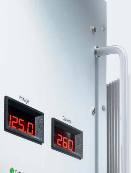
51 49 50 Options (details see page 115) Input Inrush current limitg Reverse polarity protection for put Decouplg diode for redundant / parallel operation Active current sharg for parallel operation Remote on / off (hibit) Reducg of current limitg at high ambient temperature Programmg of put voltage or current via potentiometer analog signal terface card RS232 or CAN Bus Programmg of battery chargers Temperature compensated chargg voltage Automatic / manual selection of chargg characteristic Signals via relay contacts Power ok (put) ok (put) Monitorg of put / put voltage or current via analog signal terface card RS232 or CAN Bus Mechanics / environment: Wall mount Digital or analog V- and A-meter Increased mechanical strength Tropical protection Extended temperature range to 40 C
52 High Power Converters from 5 to 40kW, switchmode Selector Guide Series Power put put [kw] [V] 1-phase 3-phase 2 6 kw 6 8 kw 8 10 kw kw kw kw C / B C / B C / B C / B C / B C / B C / B C / B C / B V V V V V CW / BW CW / BW CW / BW CW / BW CW / BW CW / BW Step-Up Converters ) value (adjustable) to be advised Further Information Order example Assistance table use: 1 Select the column for put voltage range. 2 Select the row for the appropriate put voltage. 3 The tersection of both results the module required. 5.6 kw 7.5 kw Input For example: 1 put voltage = put voltage = 110 A 3 results a C 5376 module. Conversion table Height: 1 U = mm 1 U = 1.75 Width: 1 TE = 5.08 mm 1 TE = = 25.4 mm 19 = 483 mm Weight: 1 kg = 2.2 lbs ) Adj. Range C 5353 C C 5373 C C 5383 Z C 5384 Z C 5373 G C 5374 G C 5373 K C 5374 K C 5355 C C 5375 C 5379 C 5385 Z C 5389 Z C 5375 G C 5379 G C 5375 K C 5379 K C 5356 C C 5376 C C 5386 Z C 5387 Z C 5376 G C 5377 G C 5376 K C 5377 K C 5357 J C C 5377 J C 5378 C 5387 ZJ C 5388 Z C 5377 GJ C 5378 G C 5377 KJ C 5378 K C 5358 J 14 C 5378 J C 5388 ZJ C 5378 GJ C 5378 KJ
53 51 52 nomal put voltage Package Page [V] 5 V 9 V 12 V 15 V 24 V 28 V 48 V 60 V 110 V 200 V 220 V 400 V 600 V 1) 800 V 1) Eurocassette / 19 Rack mount Height [U] 19 Plug- module Height [U] Wall mount Fan cooled Liquid cooled 24 / 28 /... / / / 9 /... / / 9 /... / / / 24 /... / / 24 /... / / / 28 /... / / 24 /... / / / 60 /... / / 48 /... / / 24 /... / / 24 /... / / 28 /... / / 28 /... / / 60 /... / / 48 /... / /... / 800 dependg on module 83 Conversion diagram C F F - 40 C - 20 C 55 C 75 C 85 C C 185 F 167 F 131 F 4 F 40 F
54 High Power Series C / B / Converters 5 kw ) Input Adj. Range C 5184 Z C 5185 Z C 5189 Z C 5186 Z C 5187 Z C 5187 ZJ C 5174 G C 5175 G C 5179 G C 5176 G C 5177 G C 5177 GJ C 5174 K C 5175 K C 5179 K C 5176 K C 5177 K C 5177 KJ / Power Supplies 5 kw Input V, 3-Phase 3x % 20 % 3x % 15 % Adj. Range C 5184 V C 5185 V C 5189 V C 5186 V C 5187 V C 5187 VJ C 5194 V C 5195 V C 5199 V C 5196 V C 5197 V C 5197 VJ Battery Battery Chargers 5 kw Input V, 3-Phase Nom. 3x % 20 % 3x % 15 % Battery Voltage Range B 5182 V B 5192 V B 5184 V B 5194 V B 5186 V B 5196 V B 5187 V B 5197 V Series specific formation Input Hold-up time for put: 5ms nom. put voltage 1) put supply from PFC also suitable General optional: via speed-controlled fans (dependg on temperature) optional: 19 sub-rack (3U or 5U) with termals / bolts / bars = cl. fans


")

55 53 54 (3U) 127 mm 538 mm 204 mm (40TE) Standard Pluggable module (for 3U sub-rack) approx. 17 kg Optional 3U, 19 sub-rack with 2 modules 5U (5U) 204 mm 538 mm 127 mm (25TE) Standard Pluggable module (for 5U sub-rack) approx. 17 kg Optional 5U, 19 sub-rack with 3 modules
56 High Power Series C / B / Converters 4 kw 5 kw Input ) Adj. Range C 5250 C 5251 C 5252 C 5253 C 5254 C 5255 C 5259 C 5256 C 5257 C 5257 J C 5258 C 5258 J C 5270 C 5271 C 5272 C 5273 C 5274 C 5275 C 5279 C 5276 C 5277 C 5277 J C 5278 C 5278 J C 5280 Z C 5281 Z C 5282 Z C 5283 Z C 5284 Z C 5285 Z C 5289 Z C 5286 Z C 5287 Z C 5287 ZJ C 5288 Z C 5288 ZJ C 5270 G C 5271 G C 5272 G C 5273 G C 5274 G C 5275 G C 5279 G C 5276 G C 5277 G C 5277 GJ C 5278 G C 5278 GJ C 5270 K C 5271 K C 5272 K C 5273 K C 5274 K C 5275 K C 5279 K C 5276 K C 5277 K C 5277 KJ C 5278 K C 5278 KJ / Power Supplies 5 kw Input V, 3-Phase 3x % 20 % 3x % 20 % 3x % 15 % Adj. Range C 5260 V C 5261 V C 5262 V C 5263 V C 5264 V C 5265 V C 5269 V C 5266 V C 5267 V C 5267 VJ C 5268 V C 5268 VJ C 5280 V C 5281 V C 5282 V C 5283 V C 5284 V C 5285 V C 5289 V C 5286 V C 5287 V C 5287 VJ C 5288 V C 5288 VJ C 5290 V C 5291 V C 5292 V C 5293 V C 5294 V C 5295 V C 5299 V C 5296 V C 5297 V C 5297 VJ C 5298 V C 5298 VJ Battery Battery Chargers 5 kw Input V, 3-Phase Nom. 3x % 20 % 3x % 20 % 3x % 15 % Battery Voltage Range B 5261 V B 5281 V B 5291 V B 5262 V B 5282 V B 5292 V B 5264 V B 5284 V B 5294 V B 5266 V B 5286 V B 5296 V B 5267 V B 5287 V B 5297 V B 5268 V B 5288 V B 5298 V Series specific formation Input Hold-up time for put: 5ms nom. put voltage 1) put supply from PFC also suitable General optional: via speed-controlled fans (dependg on temperature) = cl. fans
57 U 19" 602 mm Standard 19 Plug- module kg 4U
58 High Power Series C / B / Converters 6 KW Input ) Adj. Range Battery C 5650 C 5651 C 5652 C 5653 C 5654 C 5655 C 5659 C 5656 C 5657 C 5657 J C 5658 C 5658 J C 5670 C 5671 C 5672 C 5673 C 5674 C 5675 C 5679 C 5676 C 5677 C 5677 J C 5678 C 5678 J C 5680 Z C 5681 Z C 5682 Z C 5683 Z C 5684 Z C 5685 Z C 5689 Z C 5686 Z C 5687 Z C 5687 ZJ C 5688 Z C 5688 ZJ C 5670 G C 5671 G C 5672 G C 5673 G C 5674 G C 5675 G C 5679 G C 5676 G C 5677 G C 5677 GJ C 5678 G C 5678 GJ C 5670 K C 5671 K C 5672 K C 5673 K C 5674 K C 5675 K C 5679 K C 5676 K C 5677 K C 5677 KJ C 5678 K C 5678 KJ / Power Supplies 4.5 KW 6 KW Input V, 1-Phase Input V, 3-Phase 115 ± 20 % + 15 % % 3x % 20 % 3x % 20 % 3x % 15 % Adj. Range C C 5680 C 5660 V C 5680 V C 5690 V C C 5681 C 5661 V C 5681 V C 5691 V C C 5682 C 5662 V C 5682 V C 5692 V C C 5683 C 5663 V C 5683 V C 5693 V C C 5684 C 5664 V C 5684 V C 5694 V C C 5685 C 5665 V C 5685 V C 5695 V C C 5689 C 5669 V C 5689 V C 5699 V C C 5686 C 5666 V C 5686 V C 5696 V C C 5687 C 5667 V C 5687 V C 5697 V C 5667 J 22 C 5687 J C 5667 VJ C 5687 VJ C 5697 VJ C C 5688 C 5668 V C 5688 V C 5698 V C 5668 J 11 C 5688 J C 5668 VJ C 5688 VJ C 5698 VJ Battery Chargers 4.5 KW 6 KW Input V, 1-Phase Input V, 3-Phase 115 ± 20 % Nom % % 3x % 20 % 3x % 20 % 3x % 15 % Battery Voltage Range B B 5681 B 5661 V B 5681 V B 5691 V B B 5682 B 5662 V B 5682 V B 5692 V B B 5684 B 5664 V B 5684 V B 5694 V B B 5686 B 5666 V B 5686 V B 5696 V B B 5687 B 5667 V B 5687 V B 5697 V B B 5688 B 5668 V B 5688 V B 5698 V Series specific formation Input Inrush current for 230V and 3-phase put: limited by thermistor Hold-up time for put: 5ms nom. put voltage General 1) put supply from PFC also suitable = cl. temperature controlled fans


59 " 9U 19" approx. 460 mm 6U / 9U 310/360* mm 500 mm 800 mm 6U Standard approx. 460 mm 19 Plug- module kg kg Standard 19 Plug- module kg kg 310 mm 500 mm 600 mm Optional Wall mount kg Optional Wall mount kg kg *) applicable to put current > 350 A
60 High Power Series C / B / Converters 5.6 kw 7.5 kw Input ) Adj. Range C 5353 C 5354 C 5355 C 5359 C 5356 C 5357 C 5357 J C 5358 C 5358 J C 5373 C 5374 C 5375 C 5379 C 5376 C 5377 C 5377 J C 5378 C 5378 J C 5383 Z C 5384 Z C 5385 Z C 5389 Z C 5386 Z C 5387 Z C 5387 ZJ C 5388 Z C 5388 ZJ C 5373 G C 5374 G C 5375 G C 5379 G C 5376 G C 5377 G C 5377 GJ C 5378 G C 5378 GJ C 5373 K C 5374 K C 5375 K C 5379 K C 5376 K C 5377 K C 5377 KJ C 5378 K C 5378 KJ / Power Supplies 7.5 kw Input V, 3-Phase 3x % 20 % 3x % 20 % 3x % 15 % Adj. Range C 5363 V C 5364 V C 5365 V C 5369 V C 5366 V C 5367 V C 5367 VJ C 5368 V C 5368 VJ C 5383 V C 5384 V C 5385 V C 5389 V C 5386 V C 5387 V C 5387 VJ C 5388 V C 5388 VJ C 5393 V C 5394 V C 5395 V C 5399 V C 5396 V C 5397 V C 5397 VJ C 5398 V C 5398 VJ Battery Battery Chargers 7.5 kw Input V, 3-Phase Nom. 3x % 20 % 3x % 20 % 3x % 15 % Battery Voltage Range B 5361 V B 5381 V B 5391 V B 5362 V B 5382 V B 5392 V B 5364 V B 5384 V B 5394 V B 5366 V B 5386 V B 5396 V B 5367 V B 5387 V B 5397 V B 5368 V B 5388 V B 5398 V Series specific formation Input Hold-up time for put: 4ms nom. put voltage 1) put supply from PFC also suitable General optional: via speed-controlled fans (dependg on temperature) = cl. fans
61 U 19" 602 mm Standard 19 Plug- module kg 4U
62 High Power Series C / B / Converters 8 KW Input ) Adj. Range C 5753 C 5754 C 5755 C 5759 C 5756 C 5757 C 5757 J C 5758 C 5758 J C 5773 C 5774 C 5775 C 5779 C 5776 C 5777 C 5777 J C 5778 C 5778 J C 5783 Z C 5784 Z C 5785 Z C 5789 Z C 5786 Z C 5787 Z C 5787 ZJ C 5788 Z C 5788 ZJ C 5773 G C 5774 G C 5775 G C 5779 G C 5776 G C 5777 G C 5777 GJ C 5778 G C 5778 GJ C 5773 K C 5774 K C 5775 K C 5779 K C 5776 K C 5777 K C 5777 KJ C 5778 K C 5778 KJ / Power Supplies 6.5 KW 8 KW Input V, 1-Phase Input V, 3-Phase 115 ± 20 % + 15 % % 3x % 20 % 3x % 20 % 3x % 15 % Adj. Range C C C C 5783 C 5763 V C 5783 V C 5793 V C C 5784 C 5764 V C 5784 V C 5794 V C C 5785 C 5765 V C 5785 V C 5795 V C C 5789 C 5769 V C 5789 V C 5799 V C C 5786 C 5766 V C 5786 V C 5796 V C C 5787 C 5767 V C 5787 V C 5797 V C 5767 J 32 C 5787 J C 5767 VJ C 5787 VJ C 5797 VJ C C 5788 C 5768 V C 5788 V C 5798 V C 5768 J 16 C 5788 J C 5768 VJ C 5788 VJ C 5798 VJ Battery Battery Chargers 6.5 KW 8 KW Input V, 1-Phase Input V, 3-Phase 115 ± 20 % Nom % % 3x % 20 % 3x % 20 % 3x % 15 % Battery Voltage Range B B 5781 B 5761 V B 5781 V B 5791 V B B 5782 B 5762 V B 5782 V B 5792 V B B 5784 B 5764 V B 5784 V B 5794 V B B 5786 B 5766 V B 5786 V B 5796 V B B 5787 B 5767 V B 5787 V B 5797 V B B 5788 B 5768 V B 5788 V B 5798 V Series specific formation Input Hold-up time for put: 4ms nom. put voltage 1) put supply from PFC also suitable General = cl. temperature controlled fans

63 U 6U 19" approx. 460 mm Standard 19 Plug- module kg kg Standard 19" approx. 460 mm 6U / 9U 19 Plug- module kg kg 310 mm 500 mm 600 mm Optional Wall mount kg 310/360* mm 500 mm 800 mm Optional Wall mount kg kg *) applicable to put current > 350 A
64 High Power Series C / B / Converters 7.5 KW 10 KW Input ) Adj. Range C 5454 C 5455 C 5459 C 5456 C 5457 C 5457 J C 5458 C 5458 J C 5474 C 5475 C 5479 C 5476 C 5477 C 5477 J C 5478 C 5478 J C 5484 Z C 5485 Z C 5489 Z C 5486 Z C 5487 Z C 5487 ZJ C 5488 Z C 5488 ZJ C 5474 G C 5475 G C 5479 G C 5476 G C 5477 G C 5477 GJ C 5478 G C 5478 GJ C 5474 K C 5475 K C 5479 K C 5476 K C 5477 K C 5477 KJ C 5478 K C 5478 KJ / Power Supplies 10 KW Input V, 3-Phase 3x % 20 % 3x % 20 % 3x % 15 % Adj. Range C 5464 V C 5465 V C 5469 V C 5466 V C 5467 V C 5467 VJ C 5468 V C 5468 VJ C 5484 V C 5485 V C 5489 V C 5486 V C 5487 V C 5487 VJ C 5488 V C 5488 VJ C 5494 V C 5495 V C 5499 V C 5496 V C 5497 V C 5497 VJ C 5498 V C 5498 VJ Battery Battery Chargers 10 KW Input V, 3-Phase Nom. 3x % 20 % 3x % 20 % 3x % 15 % Battery Voltage Range B 5462 V B 5482 V B 5492 V B 5464 V B 5484 V B 5494 V B 5466 V B 5486 V B 5496 V B 5467 V B 5487 V B 5497 V B 5468 V B 5488 V B 5498 V Series specific formation Input Hold-up time for put: 2.5ms nom. put voltage 1) put supply from PFC also suitable General optional: via speed-controlled fans (dependg on temperature) = cl. fans
65 U 19" 602 mm Standard 19 Plug- module kg 4U
66 High Power Series C / B / Converters 12 KW Input ) Adj. Range C 5854 C 5855 C 5859 C 5856 C 5857 C 5857 J C 5858 C 5858 J C 5874 C 5875 C 5879 C 5876 C 5877 C 5877 J C 5878 C 5878 J C 5884 Z C 5885 Z C 5889 Z C 5886 Z C 5887 Z C 5887 ZJ C 5888 Z C 5888 ZJ C 5874 G C 5875 G C 5879 G C 5876 G C 5877 G C 5877 GJ C 5878 G C 5878 GJ C 5874 K C 5875 K C 5879 K C 5876 K C 5877 K C 5877 KJ C 5878 K C 5878 KJ / Power Supplies 8.5 KW 12 KW Input V, 1-Phase Input V, 3-Phase 115 ± 20 % + 15 % % 3x % 20 % 3x % 20 % 3x % 15 % Adj. Range C C C 5884 C 5864 V C 5884 V C 5894 V C C 5885 C 5865 V C 5885 V C 5895 V C C 5889 C 5869 V C 5889 V C 5899 V C C 5886 C 5866 V C 5886 V C 5896 V C C 5887 C 5867 V C 5887 V C 5897 V C 5867 J 42 C 5887 J C 5867 VJ C 5887 VJ C 5897 VJ C C 5888 C 5868 V C 5888 V C 5898 V C 5868 J 21 C 5888 J C 5868 VJ C 5888 VJ C 5898 VJ Battery Battery Chargers 8.8 KW 12 KW Input V, 1-Phase Input V, 3-Phase 115 ± 20 % Nom % % 3x % 20 % 3x % 20 % 3x % 15 % Battery Voltage Range B B B 5882 B 5862 V B 5882 V B 5892 V B B 5884 B 5864 V B 5884 V B 5894 V B B 5886 B 5866 V B 5886 V B 5896 V B B 5887 B 5867 V B 5887 V B 5897 V B B 5888 B 5868 V B 5888 V B 5898 V Series specific formation Input Hold-up time for put: 2.5ms nom. put voltage 1) put supply from PFC also suitable = cl. temperature controlled fans
67 U 6U 19" approx. 460 mm Standard 19 Plug- module kg kg Standard 19" approx. 460 mm 6U / 9U 19 Plug- module kg kg 310 mm 500 mm 600 mm Optional Wall mount kg 310/360* mm 500 mm 800 mm Optional Wall mount kg kg *) applicable to put current > 350 A
68 High Power Series C / B / Converters 22 KW Input Adj. Range C 6479 G C 6476 G C 6477 G C 6477 GJ C 6478 G C 6478 GJ C 6477 GH C 6479 K C 6476 K C 6477 K C 6477 KJ C 6478 K C 6478 KJ C 6477 KH tba 1) C 6478 GH C 6478 KH 27 tba 1) / Power Supplies 22 KW Input V, 3-Phase 3x % 20 % 3x % 15 % Adj. Range C 6489 V C 6486 V C 6487 V C 6487 VJ C 6488 V C 6488 VJ C 6487 VH C 6499 V C 6496 V C 6497 V C 6497 VJ C 6498 V C 6498 VJ C 6497 VH tba 1) C 6488 VH C 6498 VH 27 tba 1) Battery Battery Chargers 22 KW Input V, 3-Phase Nom. 3x % 20 % 3x % 15 % Battery Voltage Range B 6484 V B 6494 V B 6486 V B 6496 V B 6487 V B 6497 V B 6488 V B 6498 V Series specific formation Input Hold-up time for put: 2.5ms nom. put voltage General optional: via speed-controlled fans (dependg on temperature) 1) tba = to be advised = cl. fans
69 U Standard 19" 600 mm 19 Plug- module approx. 90 kg 8U
70 High Power Series C / B / Converters 30 KW Input Adj. Range C 6674 G C 6675 G C 6679 G C 6676 G C 6677 G C 6677 GJ C 6678 G C 6678 GJ C 6677 GH C 6674 K C 6675 K C 6679 K C 6676 K C 6677 K C 6677 KJ C 6678 K C 6678 KJ C 6677 KH tba 1) C 6678 GH C 6678 KH 38 tba 1) / Power Supplies 30 KW Input V, 3-Phase 3x % 20 % 3x % 15 % Adj. Range C 6684 V C 6685 V C 6689 V C 6686 V C 6687 V C 6687 VJ C 6688 V C 6688 VJ C 6687 VH C 6694 V C 6695 V C 6699 V C 6696 V C 6697 V C 6697 VJ C 6698 V C 6698 VJ C 6697 VH tba 1) C 6688 VH C 6698 VH 38 tba 1) Battery Battery Chargers 30 KW Input V, 3-Phase Nom. 3x % 20 % 3x % 15 % Battery Voltage Range B 6682 V B 6692 V B 6684 V B 6694 V B 6686 V B 6696 V B 6687 V B 6697 V B 6688 V B 6698 V Series specific formation Input Hold-up time for put: 2.5ms nom. put voltage General optional: via speed-controlled fans (dependg on temperature) 1) tba = to be advised = cl. fans

71 U Standard 19" 600 mm 19 Plug- module approx. 115 kg 10U
72 High Power Series CW / BW 5300 liquid cooled / Converters 5.6 kw 8 kw Input ) Adj. Range CW 5353 CW 5354 CW 5355 CW 5359 CW 5356 CW 5357 CW 5357 J CW 5358 CW 5358 J CW 5373 CW 5374 CW 5375 CW 5379 CW 5376 CW 5377 CW 5377 J CW 5378 CW 5378 J CW 5383 Z CW 5384 Z CW 5385 Z CW 5389 Z CW 5386 Z CW 5387 Z CW 5387 ZJ CW 5388 Z CW 5388 ZJ CW 5373 G CW 5374 G CW 5375 G CW 5379 G CW 5376 G CW 5377 G CW 5377 GJ CW 5378 G CW 5378 GJ CW 5373 K CW 5374 K CW 5375 K CW 5379 K CW 5376 K CW 5377 K CW 5377 KJ CW 5378 K CW 5378 KJ / Power Supplies 8 kw Input V, 3-Phase 3x % 20 % 3x % 20 % 3x % 15 % Adj. Range CW 5363 V CW 5364 V CW 5365 V CW 5369 V CW 5366 V CW 5367 V CW 5367 VJ CW 5368 V CW 5368 VJ CW 5383 V CW 5384 V CW 5385 V CW 5389 V CW 5386 V CW 5387 V CW 5387 VJ CW 5388 V CW 5388 VJ CW 5393 V CW 5394 V CW 5395 V CW 5399 V CW 5396 V CW 5397 V CW 5397 VJ CW 5398 V CW 5398 VJ Battery Battery Chargers 8 kw Input V, 3-Phase Nom. 3x % 20 % 3x % 20 % 3x % 15 % Battery Voltage Range BW 5361 V BW 5381 V BW 5391 V BW 5362 V BW 5382 V BW 5392 V BW 5364 V BW 5384 V BW 5394 V BW 5366 V BW 5386 V BW 5396 V BW 5367 V BW 5387 V BW 5397 V BW 5368 V BW 5388 V BW 5398 V Series specific formation Input Hold-up time for put: 5ms nom. put voltage General 1) put supply from PFC also suitable = liquid cooled
73 U 19" 600 mm Standard 19 Plug- module approx kg rear view 5U
74 High Power Series CW / BW 5400 liquid cooled / Converters 10 kw ) Input Adj. Range CW 5483 Z CW 5484 Z CW 5485 Z CW 5489 Z CW 5486 Z CW 5487 Z CW 5487 ZJ CW 5488 Z CW 5488 ZJ CW 5473 G CW 5474 G CW 5475 G CW 5479 G CW 5476 G CW 5477 G CW 5477 GJ CW 5478 G CW 5478 GJ CW 5473 K CW 5474 K CW 5475 K CW 5479 K CW 5476 K CW 5477 K CW 5477 KJ CW 5478 K CW 5478 KJ / Power Supplies 10 kw Input V, 3-Phase 3x % 20 % 3x % 15 % Adj. Range CW 5483 V CW 5484 V CW 5485 V CW 5489 V CW 5486 V CW 5487 V CW 5487 VJ CW 5488 V CW 5488 VJ CW 5493 V CW 5494 V CW 5495 V CW 5499 V CW 5496 V CW 5497 V CW 5497 VJ CW 5498 V CW 5498 VJ Battery Battery Chargers 10 kw Input V, 3-Phase Nom. 3x % 20 % 3x % 15 % Battery Voltage Range BW 5481 V BW 5491 V BW 5482 V BW 5492 V BW 5484 V BW 5494 V BW 5486 V BW 5496 V BW 5487 V BW 5497 V BW 5488 V BW 5498 V Series specific formation Input Hold-up time for put: 5ms nom. put voltage General 1) put supply from PFC also suitable = liquid cooled


75 U 19" 600 mm Standard 19 Plug- module approx kg 3U
76 High Power Series CW / BW 5500 liquid cooled / Converters 7.5 KW 15 KW Input ) Adj. Range CW 5554 CW 5555 CW 5559 CW 5556 CW CW 5574 CW 5575 CW 5579 CW 5576 CW 5577 CW 5584 Z CW 5585 Z CW 5589 Z CW 5586 Z CW 5587 Z CW 5574 G CW 5575 G CW 5579 G CW 5576 G CW 5577 G CW 5574 K CW 5575 K CW 5579 K CW 5576 K CW 5577 K CW 5557 J 38 CW 5577 J CW 5587 ZJ CW 5577 GJ CW 5577 KJ CW CW 5578 CW 5588 Z CW 5578 G CW 5578 K CW 5558 J 19 CW 5578 J CW 5588 ZJ CW 5578 GJ CW 5578 KJ / Power Supplies 15 KW Input V, 3-Phase 3x % 20 % 3x % 20 % 3x % 15 % Adj. Range CW 5564 V CW 5565 V CW 5569 V CW 5566 V CW 5567 V CW 5567 VJ CW 5568 V CW 5568 VJ CW 5584 V CW 5585 V CW 5589 V CW 5586 V CW 5587 V CW 5587 VJ CW 5588 V CW 5588 VJ CW 5594 V CW 5595 V CW 5599 V CW 5596 V CW 5597 V CW 5597 VJ CW 5598 V CW 5598 VJ Battery Battery Chargers 15 KW Input V, 3-Phase Nom. 3x % 20 % 3x % 20 % 3x % 15 % Battery Voltage Range BW 5562 V BW 5582 V BW 5592 V BW 5564 V BW 5584 V BW 5594 V BW 5566 V BW 5586 V BW 5596 V BW 5567 V BW 5587 V BW 5597 V BW 5568 V BW 5588 V BW 5598 V Series specific formation Input Hold-up time for put: 5ms nom. put voltage General 1) put supply from PFC also suitable = liquid cooled
77 U 19" 600 mm Standard 19 Plug- module approx. 47 kg rear view 5U
78 High Power Series CW / BW 5600 liquid cooled / Converters 20 KW ) Input Adj. Range CW 5684 Z CW 5685 Z CW 5689 Z CW 5686 Z CW 5687 Z CW 5674 G CW 5675 G CW 5679 G CW 5676 G CW 5677 G CW 5674 K CW 5675 K CW 5679 K CW 5676 K CW 5677 K CW 5687 ZJ CW 5677 GJ CW 5677 KJ CW 5688 Z CW 5678 G CW 5678 K CW 5688 ZJ CW 5678 GJ CW 5678 KJ / Power Supplies 20 KW Input V, 3-Phase 3x % 20 % 3x % 15 % Adj. Range CW 5684 V CW 5685 V CW 5694 V CW 5695 V CW 5689 V CW 5686 V CW 5699 V CW 5696 V CW 5687 V CW 5687 VJ CW 5697 V CW 5697 VJ CW 5688 V CW 5688 VJ CW 5698 V CW 5698 VJ Battery Battery Chargers 20 KW Input V, 3-Phase Nom. 3x % 20 % 3x % 15 % Battery Voltage Range BW 5682 V BW 5692 V BW 5684 V BW 5694 V BW 5686 V BW 5696 V BW 5687 V BW 5697 V BW 5688 V BW 5698 V Series specific formation Input Hold-up time for put: 4ms nom. put voltage General 1) put supply from PFC also suitable = liquid cooled
79 U 19" 600 mm Standard 19 Plug- module approx. 47 kg rear view 5U
80 High Power Series CW / BW 6600 liquid cooled / Converters 30 KW Input Adj. Range CW 6679 G CW 6676 G CW 6679 K CW 6676 K CW 6677 G CW 6677 GJ CW 6677 K CW 6677 KJ CW 6678 G CW 6678 GJ CW 6678 K CW 6678 KJ CW 6677 GH CW 6677 KH CW 6678 GH CW 6678 KH tba 1) tba 1) / Power Supplies 30 KW Input V, 3-Phase 3x % 20 % 3x % 15 % Adj. Range CW 6689 V CW 6686 V CW 6699 V CW 6696 V CW 6687 V CW 6687 VJ CW 6697 V CW 6697 VJ CW 6688 V CW 6688 VJ CW 6698 V CW 6698 VJ CW 6687 VH CW 6697 VH 50 tba 1) CW 6688 VH CW 6698 VH 38 tba 1) Battery Battery Chargers 30 KW Input V, 3-Phase Nom. 3x % 20 % 3x % 15 % Battery Voltage Range BW 6684 V BW 6694 V BW 6686 V BW 6696 V BW 6687 V BW 6697 V BW 6688 V BW 6698 V Series specific formation Input Hold-up time for put: 5ms nom. put voltage General 1) tba = to be advised = liquid cooled
81 U 19" 600 mm Standard 19 Plug- module approx. 108 kg rear view 9U
82 High Power Series CW / BW 6700 liquid cooled / Converters 40 KW Input Adj. Range CW 6774 G CW 6775 G CW 6779 G CW 6776 G CW 6777 G CW 6777 GJ CW 6778 G CW 6778 GJ CW 6774 K CW 6775 K CW 6779 K CW 6776 K CW 6777 K CW 6777 KJ CW 6778 K CW 6778 KJ CW 6777 GH CW 6777 KH CW 6778 GH CW 6778 KH tba 1) tba 1) / Power Supplies 40 KW Input V, 3-Phase 3x % 20 % 3x % 15 % Adj. Range CW 6784 V CW 6785 V CW 6789 V CW 6786 V CW 6787 V CW 6787 VJ CW 6788 V CW 6788 VJ CW 6787 VH CW 6794 V CW 6795 V CW 6799 V CW 6796 V CW 6797 V CW 6797 VJ CW 6798 V CW 6798 VJ CW 6797 VH tba 1) CW 6788 VH CW 6798 VH 50 tba 1) Battery Battery Chargers 40 KW Input V, 3-Phase Nom. 3x % 20 % 3x % 15 % Battery Voltage Range BW 6782 V BW 6792 V BW 6784 V BW 6794 V BW 6786 V BW 6796 V BW 6787 V BW 6797 V BW 6788 V BW 6798 V Series specific formation Input Hold-up time for put: 4ms nom. put voltage General 1) tba = to be advised = liquid cooled
83 U 19" 600 mm Standard 19 Plug- module approx. 168 kg rear view 10U

84 High Power Series E Step-up converters The step-up converters are very similar to the / converters of series C, except that the step-up converters sense the voltage across the load which is the total of the battery voltage and the voltage added by the step-up converter. The step-up converter can not reduce the voltage beg applied to its put. Therefore, the load should be specified for the maximum battery voltage. For put voltage stabilization The put voltage of an e.g. battery charger with parallel connected battery varies substantially with the chargg condition of the battery. For many applications, however, the load circuit requires a better stabilized voltage. Frequently used methods for reducg the voltage variation are e.g. voltage droppg diodes. A more economical solution is given by switch mode step-up converters. These are / converters supplied from the battery with the put connected series to the battery. Due to the circuit configuration, the put of a step-up converter is not isolated from the put supply (battery). Circuit diagrams Step-up converter with common positive le Step-up converter with common negative le standard version The followg circuit diagram shows a step-up converter which can be grounded on the positive side. The voltage will be added at the negative side and the positive le is common for put and put. battery charger = + - step-up converter = + = - load optional version The followg circuit diagram shows a step-up converter which can be grounded on the negative side. The voltage will be added at the positive side and the negative le is common for put and put. battery charger + - step-up converter + - (long) cable to load sense leads load sense leads Parallel operation of step-up converters Individual load supply For more power or redundancy step-up converters may be connected parallel with active current sharg, dividually protected by fuses at the put and decouplg diodes or fuses at the put. Such systems have already been realized for 2,000. battery charger = + - = step-up converters = current sharg signal = = sense leads load For applications that require dividually stabilized voltages across the loads, the step-converters will be connected as shown the followg diagram and may be of different power ratgs. battery charger = + - step-up converters = = = sense leads = sense leads loads

85 83 84 Operation diagram Durg normal operation no voltage needs to be added and the converter runs with a mimum of power losses. The voltage at the load is slightly reduced as the current flows through the bypass diode. The bypass diode also allows for replacement of the step-up converter and should therefore be stalled externally. Durg battery discharge the converter adds the voltage that is needed to mata the required put voltage level. The maximum voltage to be added is normally less than 20 % of the total voltage. Therefore, the step-up converter needs to be designed for 20 % of the throughpower, only. voltage battery voltage normal operation, no voltage added voltage at load voltage added by step-up converter discharge of battery Example: Input: (battery) : 0 10 (step-up voltage) put voltage regulated to 50 V durg discharge of battery time Create your step-up converter Each / converter can be modified to be a step-up converter: calculate the put power of the step-up converter: max. voltage to be added x max. load current choose the suitable C series & re-name the model as E C 5353 C 5354 C 5355 C 5359 C 5356 C 5357 C 5357 J C 5358 C 5358 J 5.6 kw 7.5 kw Input ) Step-up Converters Adj. Range C 5354 C 5359 C 5357 C C 5373 C 5374 C 5375 C 5379 C 5376 C 5377 C 5377 J C 5378 C 5378 J C 5383 Z C 5384 Z C 5385 Z C 5389 Z C 5386 Z C 5387 Z C 5387 ZJ C 5388 Z C 5388 ZJ C 5373 G C 5374 G C 5375 G C 5379 G C 5376 G C 5377 G C 5377 GJ C 5378 G C 5378 GJ C 5373 K C 5374 K C 5375 K C 5379 K C 5376 K C 5377 K C 5377 KJ C 5378 K C 5378 KJ Example: 5.6 kw 7.5 kw Input (battery voltage) ) E E 5373 E 5383 Z E 5373 G E 5373 K 350 E E 5374 E 5384 Z E 5374 G E 5374 K 288 E E 5375 E 5385 Z E 5375 G E 5375 K 250 E E 5379 E 5389 Z E 5379 G E 5379 K 136 E E 5376 E 5386 Z E 5376 G E 5376 K 110 E E 5377 E 5387 Z E 5377 G E 5377 K 58 E 5357 J 28 E 5377 J E 5387 ZJ E 5377 GJ E 5377 KJ 38 E E 5378 E 5388 Z E 5378 G E 5378 K 30 E 5358 J 14 E 5378 J E 5388 ZJ E 5378 GJ E 5378 KJ 19 Voltage at load regulated to dependg on put voltage Step-up voltage

86 Inverters 1 or 3-Phase from 200VA to 45kVA, switchmode or / Inverters, / Frequency Converters & Static Switches Input voltage: V or 115/ 230V, sgle phase, Hz or 200/ 400/ 480V, three phase, Hz voltage: 115/ 230 V, sgle phase or 200/ 400/ 480V, three phases frequency: 50/ 60/ 400/ 800Hz (crystal stabilized) or programmable with Hz or Hz power: 200VA - 45kVA Features Se Wave Contuous short circuit protection Thermal shutdown with auto-restart for 1-phase verters >1.2kVA 3-phase verters >3.6kVA Suitable for complex load Surge power capability Industrial grade components Compact and robust design 3-phase put: Unsymmetrical load permissible, modular system with terchangeable verters Specifications Input Voltage range No-load put power Inrush current Hold-up time unit switches off at under- and overvoltage W for put and put >160V: limited by thermistor put: 10 ms typical Series CI: 20ms typical Immunity acc. to EN General Efficiency % Operatg temperature 20 to + 75 C optional: -40 to +75 C Load deratg 2.5%/ C above + 55 C Storage temperature -40 to + 85 C (details see page 131) Humidity = natural convection = cl. temperature controlled fans up to 95 % RH, non-condensg Safety / Construction acc. to EN / EN Protection category IP20 acc. to EN 60529, NEMA or others upon request EMI acc. to EN , class A, optionally class B C acc. to MIL -HDBK-217E (notice1) series IT: h series CI: h series IV: h voltages 115V 230V 3x200V 3x400V 3x480V or any other power from 200 VA up to 45k VA Le regulation (±10%) 0.1 % for series CI, 2 % for series IT and IV 3 % for series IT and 400Hz Load regulation (10-90%) 1 % typical, 3 % max. (400 Hz: 3 % typical, 5 % max.) Turn-on rise time soft-start, 100ms typical Waveform se wave or any wave shape programmable by external signal Frequency Hz: adjustable or programmable or any fixed frequency (crystal stabilized) Distortion 3 % typical, Hz, Hz, 800Hz Overload protection (steady state) Surge power Short circuit protection current limited to approx x nomal current 2 x nomal power for 1 s electronically limited to 3 x nomal current, unit switches off after 1 s Crest factor approx. 3 Power factor cos 0.7 ductive / capacitive

 ok (put) Monitorg of put / put voltage, current or frequency via analog signal")
 Mechanics / environment: 19 sub-rack for eurocassette, refer to page 121 Wall mount Increased")
87 85 86 Options (details see page 115) Input Inrush current limitg for put Reverse polarity protection for put Autorangg for 115 / 230 V put Special circuit for 16.6Hz put Remote on / off (hibit) Static Switch (details see page 97) Parallel operation for redundancy or creased power: series IT5xxx Signals via relay contacts Power ok (put) ok (put) Monitorg of put / put voltage, current or frequency via analog signal terface card RS232 or CAN Bus (external) Programmg of put voltage, current or frequency via potentiometer analog signal terface card RS232 or CAN Bus (external) Mechanics / environment: 19 sub-rack for eurocassette, refer to page 121 Wall mount Increased mechanical strength Tropical protection Extended temperature range to 40 C Temperature controlled fans for 19 units
88 Inverters 1 or 3-Phase from 200VA to 45kVA, switchmode Series IT - Inverters with 1-phase put from 200 VA to 15 kva Page 89 / Inverters is a combation of a switch mode Inverter and a Transformer at the put. The transformer provides the isolation between put and put and transforms the voltage to the required level. put put Inverter Transformer / Frequency Converters is a combation of a switch mode Inverter with a rectifier at the put and a Transformer at the put. The transformer provides the isolation between put and put and transforms the voltage to the required level. put put Inverter Transformer For lower put voltages the CI version is more compact than the IT version. Series CI - Inverters with 1-phase put from 400 VA to 3.5 kva Page 91 / Inverters is a combation of a switch mode Converter and Inverter. The converter provides the isolation between put and put and transforms the voltage to the level needed by the verter for supplyg the specified put voltage. put put Converter Inverter / Frequency Converters is a combation of a switch mode Converter and Inverter. The converter provides the isolation between put and put and transforms the voltage to the level needed by the verter for supplyg the specified put voltage. put put Converter Inverter Series IV - Inverters with 3-phase put from 600VA to 45 kva Page 93 / or / is a combation of 3 dividual switch mode verters with put transformers synchronized for a symmetrical 3-phase put. The transformers provide the isolation between put and put and transform the voltages to the required levels. or put 3 x Inverter 3-phase put 3 x Transformer Series SS from 800 VA to 10 kva Page 97 Static Switches The Static Switch has two puts for load supply, a priority and a non-priority put, and synchronizes the frequency of one supply to the other. Typically, but not exclusively, supplied by Mas & an Inverter, there are 3 modes of operation: 1. Service mode Mas - mas is selected as the load provider. 2. Service mode Inverter - verter is selected as the load provider. 3. Automated function with priority selection. supply 1 supply 2 1-phase put static switch Series U from 1 to 2.5 kva Page 99 UPS Systems with Static Switch provides unterrupted power to a critical load by connectg the load to mas supply 1 which can be the verter put or to supply 2 which can be the mas. Series U does not clude the batteries. The batteries can be specified and both, batteries and charger can be added to the system. = Static Switch Bypass Switch put (Load) Inverter Battery Connectors for Series CI, IT, IV & SS Page 132 Mechanics Series CI Series IT Series IV Series SS Series U Eurocassette H15 & high currrent connector for I >50 A H15 and F24H7 -- H15 and F48 -- Wall mount or 19 unit Termals Termals Termals Termals Termals
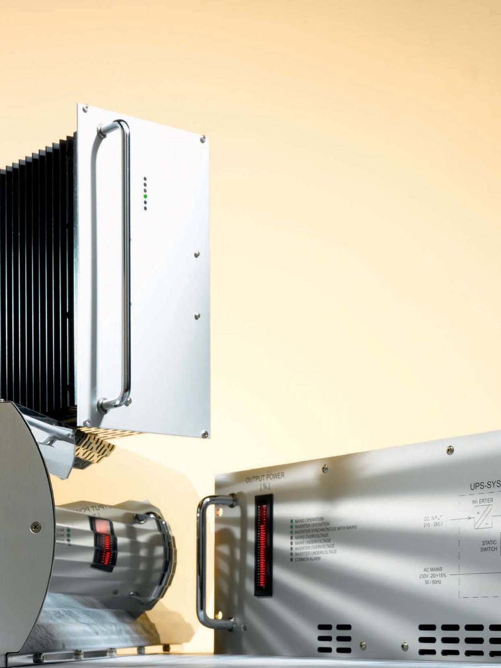
89 87 88
90 Inverters Series IT Switch mode verter and transformer put put Inverter Transformer / Inverters with 1-phase put from 200VA to 15kVA kva Size kva Size Input kva Size ) ) IT A IT 1636 IT A IT A IT 1676 IT 1686 Z 0.5 A IT 3636 IT B IT B IT 3676 IT 3686 Z IT 3676 G 1 B IT C IT 3876 IT 3886 Z IT 3876 G IT 3876 K 1.6 C IT 4836 IT D IT D IT 4876 IT 4886 Z 2.5 D IT 5636 IT 5736 IT 5646 IT E E IT 5656 IT E F + T1 IT 5676 IT 5776 IT 5876 IT 5976 IT 5686 Z IT 5786 Z IT 5886 Z IT 5986 Z IT 4876 G IT 5676 G IT 5776 G IT 5876 G IT 5976 G IT 4876 K IT 5676 K IT 5776 K IT 5876 K IT 5976 K D F + T1 F + T2 F + T3 F + T4 IT A IT 1638 IT A IT A IT 1678 IT 1688 Z 0.5 A IT 3638 IT B IT B IT 3678 IT 3688 Z IT 3678 G 1 B IT C IT 3878 IT 3888 Z IT 3878 G IT 3878 K 1.6 C IT 4838 IT D IT D IT 4878 IT 4888 Z 2.5 D IT 4878 G IT 4878 K 2.5 D IT 5638 IT E IT E IT 5678 IT 5688 Z IT 5678 G IT 5678 K 5 F + T1 IT 5738 IT E IT F+T1 IT 5778 IT 5788 Z IT 5778 G IT 5778 K 8 F + T2 IT 5878 IT 5888 Z IT 5878 G IT 5878 K 10 F + T3 IT 5978 IT 5988 Z IT 5978 G IT 5978 K 15 F + T4 = natural convection = cl. temperature controlled fans 1) standard version: wall mount kva Size V put put Inverter Transformer / Frequency Converters with 1-phase put from 500VA to 15kVA Input V 1-Phase Input V 1-Phase Size kva 115 ± 20 % % 20 % 3x % 20 % Input V 3-Phase + 15 % + 10 % 3x % 3x % kva Size V IT 1666 IT 3666 IT 3866 IT 4866 IT 5666 IT A B C D E F+T1 IT 1686 IT 3686 IT 3886 IT 4886 IT 5686 IT 5786 IT 1666 V IT 3666 V IT 3866 V IT 4866 V IT 5666 V IT 5766 V IT 3686 V IT 3886 V IT 4886 V IT 5686 V IT 5786 V IT 5886 V IT 5986 V IT 3896 V IT 4896 V IT 5696 V IT 5796 V IT 5896 V IT 5996 V A B C D F + T1 F +T2 F + T3 F +T4 IT 1668 IT 3668 IT 3868 IT 4868 IT 5668 IT A B C D E F+T1 IT 1688 IT 3688 IT 3888 IT 4888 IT 5688 IT 5788 IT 1668 V IT 3668 V IT 3868 V IT 4868 V IT 5668 V IT 5768 V IT 3688 V IT 3888 V IT 4888 V IT 5688 V IT 5788 V IT 5888 V IT 5988 V IT 3898 V IT 4898 V IT 5698 V IT 5798 V IT 5898 V IT 5998 V A B C D F + T1 F +T2 F + T3 F +T = natural convection = cl. temperature controlled fans Frequency Designation Hz adjustable / programmable Hz adjustable / programmable any fixed frequency between Hz 400 Hz synchronized with 400 Hz mas 50 Hz synchronized with 50 Hz mas 60 Hz synchronized with 60 Hz mas 50/60 Hz switchable 800 Hz
91 89 90 Size A 168 mm 220 mm Size B 229 mm 220 mm 360 mm 360 mm 6U 6U 42TE mm Standard Optional Standard Optional Eurocassette / approx. 9 kg Wall mount / approx. 11 kg Eurocassette / approx kg Wall mount / approx kg 42TE 226 mm Size C 309 mm 280 mm Size D 309 mm 280 mm 6U 360 mm Standard Optional Standard Optional Eurocassette / approx kg Wall mount / approx kg Eurocassette / approx kg Wall mount / approx kg 56TE 306 mm 310 mm 500 mm 310 mm 500 mm 6U 6U 6U 360 mm 56TE 306 mm Size E Size F 19" 460 mm 600 mm 400 mm Standard Optional Standard Optional 19 Plug- module / approx kg Wall mount / approx kg 19 Plug- module / approx. 32 kg Wall mount / approx. 36 kg Size L 19" 360 mm 3HE 19, 3U high packages: available for series IT16xx up to IT36xx. 19" 362mm = cl. temperature controlled fans Optional 19, 3U Plug- module D Size T1 - T4 W Size T1 H Trans - former H W D Weight mm kg H Trans - former H W D Weight mm kg W Standg version T1 T2 T3 T Transformers refer to 50/60 Hz. Other frequencies or tropical sulation may change size and weight. D Wall mount version T Transformers refer to 50/60 Hz. Other frequencies or tropical sulation may change size and weight.
92 Inverters Series CI Switch mode converter and verter put Converter Inverter put / Inverters with 1-phase put from 400VA to 3.5kVA CI 1606 kva Size kva Size Input ) ) 0.4 G CI G CI 1636 CI 1646 CI 1656 CI 1676 CI 1686 Z 0.6 G CI 4806 CI I K CI 3626 CI 4826 CI 5626 CI H I K K CI 3636 CI 4836 CI 5636 CI 5736 CI 3646 CI 4846 CI 5646 CI 5746 CI 3656 CI 4856 CI 5656 CI 5756 CI 3676 CI 4876 CI 5676 CI 5776 CI 3686 Z CI 4886 Z CI 5686 Z CI 5786 Z CI 3676 G CI 4876 G CI 5676 G CI 5776 G CI 4876 K CI 5676 K CI 5776 K H I K K CI G CI G CI 1638 CI 1648 CI 1658 CI 1678 CI 1688 Z 0.6 G CI H CI 3638 CI 3648 CI 3658 CI 3678 CI 3688 Z CI 3678 G 1.2 H CI I CI I CI 4838 CI 4848 CI 4858 CI 4878 CI 4888 Z CI 4878 G CI 4878 K 1.8 I CI K CI 5638 CI 5648 CI 5658 CI 5678 CI 5688 Z CI 5678 G CI 5678 K 2.4 K CI K CI K CI 5738 CI 5748 CI 5758 CI 5778 CI 5788 Z CI 5778 G CI 5778 K 3.5 K = natural convection = cl. temperature controlled fans 1) standard version: wall mount kva Size V put Converter Inverter put / Frequency Converters with 1-phase put from 600VA to 3.5kVA Input V 1-Phase 115 ± 20 % % 20 % 115 ± 20 % / % 20 % Input V 3-Phase 3x % + 15 % + 10 % 20 % 3x % 3x % kva CI 1666 CI 3666 CI 4866 CI 5666 CI 5766 CI 1686 CI 3686 CI 4886 CI 5686 CI 5786 CI 1696 CI 3696 CI 4896 CI 5696 CI 1666 V CI 3666 V CI 4866 V CI 5666 V CI 5766 V CI 3686 V CI 4886 V CI 5686 V CI 5786 V CI 3696 V CI 4896 V CI 5696 V CI 5796 V G H I K K CI 1668 CI 1688 CI 1698 CI 1668 V 0.6 G CI 3668 CI 3688 CI 3698 CI 3668 V CI 3688 V CI 3698 V 1.2 H CI 4868 CI 4888 CI 4898 CI 4868 V CI 4888 V CI 4898 V 1.8 I CI 5668 CI 5688 CI 5698 CI 5668 V CI 5688 V CI 5698 V 2.4 K CI 5768 CI 5788 CI 5768 V CI 5788 V CI 5798 V 3.5 K Size V = natural convection = cl. temperature controlled fans Frequency Designation any external signal (control, ramp) > only for Series CI Hz adjustable / programmable Hz adjustable / programmable any fixed frequency between Hz 400 Hz synchronized with 400 Hz mas 50 Hz synchronized with 50 Hz mas 60 Hz synchronized with 60 Hz mas 50/60 Hz switchable 800 Hz
93 91 92 Size G 168 mm 220 mm Size H 229 mm 220 mm 360 mm 360 mm 6U 6U 42TE mm 42TE 226 mm Standard Optional Standard Optional Eurocassette / approx. 6 kg Wall mount / approx. 8 kg Eurocassette / approx. 10 kg Wall mount / approx. 12 kg Size I 309 mm 280 mm Size K 310 mm 500 mm 6U 56TE 306 mm 360 mm 6U 19" 460 mm* 400 mm 600 mm** Standard Optional Standard Optional Eurocassette / approx. 18 kg Wall mount / approx. 21 kg 19 Plug- module / approx kg *) less depth upon request Size M Wall mount / approx kg **) applicable for CI 5706, and HE 19, 2U high packages: available for series CI16xx. = cl. temperature controlled fans 19" 362mm Optional 19, 2U Plug- module
94 Inverters Series IV Switch mode verters with put transformers for isolation and voltage transformation put 3-phase put / Inverters with 3-phase put from 0.6 to 45kVA 3 x Inverter 3 x Transformer kva Size kva Size Input kva Size ) ) IV A IV 5536 IV A IV A IV 5576 IV 5586 Z 1.8 A IV 5636 IV B IV C IV 5676 IV 5776 IV 5686 Z IV 5786 Z IV 5676 G C D + T2 IV 5776 G IV 5776 K 5.4 D + T2 IV 5836 IV E + T1 IV E + T2 IV 6236 IV G+T2 IV IV 5876 IV 5876 F 2) G +T3 IV 6276 IV 5886 Z IV 5886 ZF IV 6286 Z IV 5876 G IV 5876 GF 2) IV 6276 G IV 5876 K IV 5876 KF 2) IV 6276 K F+T3 F + T4 G+T5 IV 6436 IV G + T3 IV G +T5 IV 6476 IV 6676 IV 6876 IV 6486 Z IV 6686 Z IV 6886 Z IV 6476 G IV 6676 G IV 6876 G IV 6476 K IV 6676 K IV 6876 K G + T6 G+T7 G + T8 IV A IV 5538 IV A IV A IV 5578 IV 5588 Z 1.8 A IV 5638 IV B IV C IV 5678 IV 5688 Z IV 5678 G 3.6 C IV 5778 IV 5788 Z 5.4 D + T2 IV 5778 G IV 5778 K 5.4 D + T2 IV 5838 IV E + T1 IV E+T2 IV 5878 IV 5888 Z IV 5878 G IV 5878 K 7.5 F + T3 IV 5878 F 2) IV 5888 ZF IV 5878 GF 2) IV 5878 KF 2) 10 F+T4 IV 6278 IV 6288 Z IV 6278 G IV 6278 K 15 G+ T5 IV 6238 IV G+T2 IV G+T3 IV 6478 IV 6488 Z IV 6478 G IV 6478 K 24 G+T6 IV 6438 IV G + T3 IV G +T5 IV 6678 IV 6688 Z IV 6678 G IV 6678 K 30 G + T7 IV 6878 IV 6888 Z IV 6878 G IV 6878 K 45 G+T8 IV A IV 5539 IV A IV A IV 5579 IV 5589 Z 1.8 A IV 5639 IV B IV C IV 5679 IV 5779 IV 5689 Z IV 5789 Z IV 5679 G C D + T2 IV 5779 G IV 5779 K 5.4 D + T2 IV 5839 IV E + T1 IV E + T2 IV 5879 IV 5889 Z IV 5879 G IV 5879 K 7.5 F+T3 IV 5879 F 2) IV 5889 ZF IV 5879 GF 2) IV 5879 KF 2) 10 F + T4 IV 6239 IV 6439 IV 6249 IV G+T2 G + T3 IV 6259 IV G+T3 IV 6279 G +T5 IV 6479 IV 6679 IV 6879 IV 6289 Z IV 6489 Z IV 6689 Z IV 6889 Z IV 6279 G IV 6479 G IV 6679 G IV 6879 G IV 6279 K IV 6479 K IV 6679 K IV 6879 K G+T5 G + T6 G+T7 G + T8 = natural convection = cl. temperature controlled fans 1) standard version: wall mount 2) put voltage range to be narrowed kva Size V le-to-le 3 x x x 480 Frequency Designation Hz adjustable / programmable Hz adjustable / programmable any fixed frequency between Hz 400 Hz synchronized with 400 Hz mas 50 Hz synchronized with 50 Hz mas 60 Hz synchronized with 60 Hz mas 50/60 Hz switchable 800 Hz
95 93 94 m m Size A 0m 0m 0m Size B m m 19 " 600 mm 400 mm 6U 6U m 19 m " m 0m 6m Standard Standard Optional 19 sub-rack / approx kg *) with wall plate / approx kg *) m 0m with wall plate / approx. 38 kg *) m 50 0m 33 0m Size D m 0m m 600 mm 600 mm 6U 6U Size C Optional 19 sub-rack / approx. 33 kg *) 19 " m 19 0m " m 0m Standard Standard Optional 19 sub-rack / approx. 40 kg *) with wall plate / approx. 45 kg *) 0 37 mm m 0m m m m 0m " Standard 0m 800 mm Standard Optional 19 sub-rack / approx. 27 kg **) 50 7U m 0m " 0m 37 Size F 6U 19 with wall plate / approx. 65 kg *) / 800 mm Size E Optional 19 sub-rack / approx. 24 kg **) with wall plate / 58/ 70/ 80kg *) Optional 19 sub-rack / approx. 28 kg **) with wall plate / approx. 104 kg *) m Size G 0m m 6U m 400 mm Attention: For 3-phase system 3 modules are required. 19 " m 0m 36 Standard Optional 19 Plug- module / approx. 32 kg with wall plate / approx. 36 kg Size T1 - T3 H T1 T2 T H mm Size T4 Weight kg Power kva Transformer refers to 50/60 Hz at the put. Other frequencies or tropical sulation may change size and weight. Attention: For 3-phase system 3 transformers are required. 200 mm Transformer Ø 19 2m Transformers refer to 50/60 Hz at the put.other frequencies or tropical sulation may change size and weight. Attention: For 3-phase system 3 transformers are required. Transformer H T5 T6 T7 T W W D Weight kg Power kva H standg version *) transformers ternal Transformers refer to 50/60 Hz at the put.other frequencies or tropical sulation may change size and weight. Attention: For 3-phase system 3 transformers are required. **) transformers external Size T5 Transformer H T5 335 W D Weight kg Power kva mm H mm approx. 23 kg / 3.4 kva Size T5 - T8 D W m 6m m Ø 230 Transformers refer to 50/60 Hz at the put.other frequencies or tropical sulation may change size and weight. Attention: For 3-phase system 3 transformers are required. D Wall mount version
96 Inverters Series IV Switch mode verters with put transformers for isolation and voltage transformation put 1 or 3-ph. 3-phase put / Inverters with 3-phase put from 1.5kVA to 45kVA 3 x Inverter with put rectifier 3 x Transformer Input V 1-Phase Input V 1-Phase Size kva 115 ± 20 % % 20 % 3x % 20 % Input V 3-Phase 3x % 20 % 3x % 15 % kva IV 5566 IV 5666 IV 5766 IV 5866 IV 6266 IV A C D+T1 E+T2 G+T3 G+T5 IV 5586 IV 5686 IV 5786 IV 5886 IV 6286 IV 6486 IV 5566 V IV 5666 V IV 5766 V IV 5866 V IV 6266 V IV 6466 V IV 5686 V IV 5786 V IV 5886 V IV 5886 VF IV 6286 V IV 6486 V IV 6686 V IV 6886 V IV 5796 V IV 5896 V IV 5896 VF IV 6296 V IV 6496 V IV 6696 V IV 6896 V A C D + T2 E +T3 F + T4 G+T5 G + T6 G+T7 G+ T8 IV A IV 5588 IV 5568 V 1.8 A IV C IV 5688 IV 5668 V IV 5688 V 3.6 C IV D+T1 IV 5788 IV 5768 V IV 5788 V IV 5798 V 5.4 D+T2 IV E + T2 IV 5888 IV 5868 V IV 5888 V IV 5898 V 7.5 E + T3 IV 5888 VF IV 5898 VF 10 F+T4 IV G+T3 IV 6288 IV 6268 V IV 6288 V IV 6298 V 15 G + T5 IV G+T5 IV 6488 IV 6468 V IV 6488 V IV 6498 V 24 G+T6 IV 6688 V IV 6698 V 36 G + T7 IV 6888 V IV 6898 V 45 G+T8 IV 5569 IV 5669 IV 5769 IV 5869 IV 6269 IV A C D+T1 E+T2 G+T3 G+T5 IV 5589 IV 5689 IV 5789 IV 5889 IV 6289 IV 6489 IV 5569 V IV 5669 V IV 5769 V IV 5869 V IV 6269 V IV 6469 V IV 5689 V IV 5789 V IV 5889 V IV 5889 VF IV 6289 V IV 6489 V IV 6689 V IV 6889 V IV 5799 V IV 5899 V IV 5899 VF IV 6299 V IV 6499 V IV 6699 V IV 6899 V A C D + T2 E +T3 F + T4 G+T5 G + T6 G+T7 G + T8 = natural convection = cl. temperature controlled fans Size V le-to-le 3 x x x 480 Frequency Designation Hz adjustable / programmable Hz adjustable / programmable any fixed frequency between Hz 400 Hz synchronized with 400 Hz mas 50 Hz synchronized with 50 Hz mas 60 Hz synchronized with 60 Hz mas 50/60 Hz switchable 800 Hz
97 95 96 m Size A 0m m 400 mm 6U m 19 " m 0m 35 Standard Optional 19 sub-rack / approx. 27 kg *) with wall plate / approx. 31 kg *) m 0m m 50 0m 33 0m Size D m 0m m 600 mm 600 mm 6U 6U Size C 19 " m 19 0m " m 0m Standard Standard Optional 19 sub-rack / approx. 40 kg *) with wall plate / approx. 45 kg *) 0 37 mm with wall plate / 55/65 kg *) m 50 0m 0m 37 Size F m 50 0m m 800 mm 800 mm 6U 7U Size E Optional 19 sub-rack / approx. 24 kg **) 19 m 19 0m " m 0m " 46 Standard Standard Optional 19 sub-rack / approx. 27 kg **) 46 with wall plate / approx. 70/80kg*) Optional 19 sub-rack / approx. 28 kg **) with wall plate / approx. 104 kg *) m Size G 0m m 6U m 400 mm Attention: For 3-phase system 3 modules are required. 19 " m 0m 36 Standard Optional 19 Plug- module / approx. 32 kg with wall plate / approx. 36 kg Size T1 - T3 H T1 T2 T H mm Size T4 Weight kg Power kva Transformer refers to 50/60 Hz at the put. Other frequencies or tropical sulation may change size and weight. Attention: For 3-phase system 3 transformers are required. 200 mm Transformer Ø 19 2m Transformers refer to 50/60 Hz at the put.other frequencies or tropical sulation may change size and weight. Attention: For 3-phase system 3 transformers are required. Transformer H T5 T6 T7 T W W D Weight kg Power kva H standg version *) transformers ternal Transformers refer to 50/60 Hz at the put.other frequencies or tropical sulation may change size and weight. Attention: For 3-phase system 3 transformers are required. **) transformers external Size T5 Transformer H T5 335 W D Weight kg Power kva mm H mm approx. 23 kg / 3.4 kva Size T5 - T8 D W m 6m m Ø 230 Transformers refer to 50/60 Hz at the put.other frequencies or tropical sulation may change size and weight. Attention: For 3-phase system 3 transformers are required. D Wall mount version
98 Inverters Series SS Static Switches supply 1 supply 2 1-phase put static switch Static Switches with 1-phase put from 0.8 to 10kVA Model Power [kva] Input / [V] SS 1506 SS 3506 SS SS 3526 SS SS 1508 SS 3508 SS 3518 SS 3528 SS Frequency Designation Hz 50 Hz 60 Hz 800Hz = natural convection Series specific formation Function The Static Switch has two puts for load supply, a priority and a nonpriority put, and synchronizes the frequency of one supply to the other. Typically, but not exclusively, supplied by Mas and an Inverter, there are 3 modes of operation: 1. Service mode Mas - mas is selected as the load provider. 2. Service mode Inverter - verter is selected as the load provider. 3. Automated function with priority selection. In the automated function the supply of the priority put is connected to the load. If the static switch detects deviation from tolerance through monitorg, it will transfer the load to the non-priority put. When the supply of the priority put has returned to be with parameters of voltage and frequency, the static switch reverses this selection. For adaptg the static switch to different requirements, the priority for mas or verter operation can be selected externally via an optocoupler. The static switch can also be hibited via another opto-coupler for disconnectg the load. LEDs and potential-free relay contacts dicate the mode of operation and / or the status of alarms. Indication of operation mode Green Red potential LED LED free contacts *) Mas operation Inverter operation Inverter synchronous with mas Mas over voltage Mas under voltage Inverter over voltage Inverter under voltage Common alarm Service mode *) U max = 250 V, I max = 3 A Input / Surge current 5 x I nom for 1 s Overload protection For models with I nom 15 A: short circuit protected: unit switches off at put current above 15 A; For models with I nom > 15 A: an external fuse with slow characteristic is required Inhibit (remote on / off) logic low = 0 5 V; logic high = V via opto-coupler Priority selection logic low = 0 5 V; logic high = V via opto-coupler Transfer trigger 0.8 x U nom < voltage < 1.15 x U nom Transfer time - mas to verter (mas For models with I nom 15 A: priority) or verter to ½ period, typically ¼ period mas (verter priority) (cludg failure detection time) For models with I nom > 15 A: one period, typically ½ period (cludg failure detection time) - return to mas (mas For models with I nom 15 A: priority) or return to practically no terruption verter (verter priority) For models with I nom > 15 A: typically ½ period Options Mechanics / environment 19 sub-rack for eurocassette, refer to page 121 Wall mount Increased mechanical strength Tropical protection Extended temperature range to 40 C


 approx. 5.")
99 97 98 series SS 15xx 6U Standard 21TE mm Eurocassette (pluggable module for 19 sub-rack) approx. 3.3 kg series SS 15xx 260 mm 140 mm 360 mm 6U Optional Wall mount approx. 6.3 kg series SS 35xx 6U 21TE 226 mm Standard Eurocassette (pluggable module for 19 sub-rack) approx. 5.0 kg series SS 35xx 260 mm 140 mm 360 mm Optional Wall mount approx. 8.0 kg
100 Inverters Series U Unterruptible Power Supply Systems UPS with 1-phase put from 1 to 2.5kVA kva U 5436 U U 5438 U Input kva kva U U U U U U U U U U U U Input / V Frequency Designation Hz 50 Hz 60 Hz = cl. temperature controlled fans Series specific formation Function The UPS provides unterrupted power to a critical load, beg supplied either by mas or by batteries via the ternal verter. In the automated function the supply of the priority put (mas) is connected to the load. If the ternal static switch detects deviation from tolerance, it will transfer the load to the non-priority put (verter). When the supply of the priority put has returned to be with parameters of voltage and frequency, the static switch reverses this selection. Input / Transfer time - mas to verter (mas priority) or verter to mas (verter priority) - return to mas (mas priority) or return to verter (verter priority) Transfer trigger ½ period, typically ¼ period (cludg failure detection time) practically no terruption 0.8 x U nom < voltage < 1.15 x U nom For adaptg the UPS to different requirements, the priority for mas or verter operation can be selected externally via switch on the rear side of the UPS. The UPS can also be hibited either via opto-coupler or via external relay contact for disconnectg the load. LEDs dicate the mode of operation and / or the status of alarms. A potential-free relay contact is given for common alarm. Optionally, a manual bypass switch can be provided for connectg the load directly to the mas while disconnectg the UPS or the batteries case of matenance. For maximum flexibility the batteries (external) can be specified accordg to the requirements on site and a suitable battery charger (external) can be chosen from the Schaefer product range. UPS System Indication of operation mode Mas operation Inverter operation Inverter synchronous with mas Mas over voltage Mas under voltage Inverter over voltage Inverter under voltage Common alarm cl. potential free contact*) *) U max = 250 V, I max = 3 A Green LED Red LED mas Static Switch Bypass Switch put (Load) = Inverter Battery


101 U 19" 535 mm Standard 19 Plug- module approx kg 4U

102 Harmonic Filters Active Harmonic Filters from 60 to Power Balance Series Features Modular system 60 A to 300 A extendable Harmonic compensation for 3-wire and 4-wire technology Up to 50th harmonic each dividually selectable Ultrafast reactive power compensation Flicker compensation Load balancg between phases and unload neutral wire Grid resonancy detection Ethernet and Ethercat system for terconnection Subsystems Display control unit, Active sensor unit, ModBus, PQ Analyzer Specifications Input & Parameters Connectivity 3-wire: 3 phase 4-wire: 3 phase + neutral lead Phase compensation current 60A 120A 180A 240A 300A Neutral lead compensation current 180A 360A 540A 720A 900A Input voltage 3-wire: 200 V V ± 10% 4-wire: 200 V V ± 10% Frequency 50/60 Hz ± 3 Hz Reaction time 21μs (immediate load change reaction) Staedy state response time < 300μs (steady state response time to full steady state compensation) Switchg frequency 24 khz Control frequency 48 khz Digital control algorithm Selective Direct Control algorithm Compensation up to 49th harmonic Individually selectable degree of compensation Control functions Harmonic compensation Reactice power compensation, adjustable power factor Reactive power jection (overcompensation) Load balancg Power factor correction Fully ductive and reactive current compensation from 0 to 100% Overload current 150A 300A 450A @cf2.5 Current transformer Source or Load side selectable, Primary current range 100 A A, secondary current 1 A Maximum power losses (W) Weight sgle unit 60 kg Weight cludg cabett 90kg 150kg 210kg 270kg 330kg Dimensions sgle unit 19 x 678 x 5U (W x D x H) Dimensions cludg cabett (mm) 570 x 815 x 808 Air flow rate 470 cfm 570 x 815 x cfm 570 x 815 x cfm 570 x 815 x cfm 570 x 815 x cfm Interface Ethercat 100 Mbit/s, USB, Active sensor bus, Display bus Ambient temperature -10 C to + 40 C full performance, up to +55 C deratg 2% / K = cl. temperature controlled fans Humidity 95% non condensg

: 308 x 45 x 135 mm")


103 Options TFT 07 7 TFT control unit Input: 5 key navigation Operatg system: embedded Lux Communication: Ethercat Master, Ethernet TCP/IP Interface: USB, Digital I/O, Display bus Dimensions (W x D x H): 308 x 45 x 135 mm Basic functionality: parameter settg, status dication, alarmg, monitorg, event loggg TFT TFT control unit Input: touchscreen Operatg system: embedded Lux Communication: Ethercat Master, Ethernet TCP/IP Interface: USB, Digital I/O, Display bus Dimensions (W x D x H): 308 x 50 x 240 mm Basic functionality: parameter settg, status dication alarmg, monitorg, event loggg Extended functionality: power quality analyzer SU Active sensor unit Interface: Active sensor bus Dimensions (W x D x H): 186 x 90 x 35 mm Basic functionality: Source or Load side selectable, primary current range 100 A A, secondary current 1A


104 Harmonic Filters Series PB Modular System PB Module consistg of one module 1 sensor unit 1 display PB Module consistg of two modules 1 sensor unit 1 display PB Module consistg of three modules 1 sensor unit 1 display PB Module consistg of four modules 1 sensor unit 1 display PB Module consistg of five modules 1 sensor unit 1 display General Information The PB-SERIES is an active harmonic filter system for tower buildgs as well as automation, wdturbe and various other dustrial applications elimatg harmonic oscillations and consequently costs for reactive energy. The filter monitors the current signal & compen- sates for the unwanted elements of the measured current. Thus, the filter ensures a harmonic suppression dependently of the number of loads. Furthermore the filter corrects the power factor, improvg the systems efficiency while reducg harmonic pollution. PB Active Harmonic Filter With POWER BALANCE: Harmonic disturbances caused by e.g. non-lear loads. With POWER BALANCE: Reactive power & harmonic oscillations are actively compensated.


105 U mm Standard 19 Plug- module approx. 60 kg 5U

106 Electronic Loads Electronic Loads liquid cooled P WATER INLET WATER OUTLET LW 5100 Series Features Regulation of voltage, current, power and resistance Wide operatg range up to 400V / up to 750A with one module Parallelg of up to 4 modules for higher load capacity Reduced water consumption dependg on load power and water let temperature CAN Bus terface for control and monitorg Protected agast thermal overheatg Determation of the capacity of batteries Ah (battery tester) / In service test of batteries considerg actual load currents by an additional current probe put Programmable switch off limits to avoid total discharge of the battery Specifications Input Voltage range Load current Load power Auxiliary put voltage Master-Slave configuration Interface V A max. 10kW V / 2A, 50/60Hz Expandable up to 40kW CAN Bus General Operatg temperature C optional: -20 to +50 C liquid temperature up to +35 C liquid pressure up to 6 bar liquid flow rate Dependg on load power and coolg liquid temperature at the liquid let, up to 30l/m Storage temperature -20 to +70 C optional: -30 to +80 C Humidity up to 95% RH, non-condensg Safety / Construction acc. to EN / EN Protection category IP20 acc. to EN Connectors termal, bolts, bars Options remote control unit extended temperature range Control Regulation Adjustment / Control Modulation Display Monitorg Control of external lear valves for liquid coolg Constant voltage (CV), constant current (CC), constant resistance (CR), constant power (CP) - CV, CC, CR, CP programmable by potentiometers on the front plate, external control unit (remote control) and CAN - Inhibit selectable by push-button on the front plate, external control unit (remote control) and CAN Modulation of voltage, current, power by usg ternal stored waveforms. Offset, amplitude and frequency adjustable. Indication of actual values like voltage, current, resistance, power, temperature; status by LCD display Monitorg of actual values like voltage, current and power by V, mA or mA signal and CAN V / 10mA max. Parallel operation Power crease by parallelg up to 4 units (40kW)
. Constant resistance mode operates / Volt.")
107 Load characteristics CV Constant Voltage CC Constant Current 0 tp to 400V. 1 up to 750A (per module). U U I I CP Constant Power CR Constant Resistance 0 up to 10kW (per module). Constant resistance mode operates / Volt. U U I I


108 Electronic Loads Series LW P WATER INLET WATER OUTLET Modular System 1 x LW Module consistg of cabet one module 2 x LW Modules consistg of cabet two modules 3 x LW Modules consistg of cabet three modules 4 x LW Modules consistg of cabet four modules P WATER INLET WATER OUTLET General Information This liquid cooled load allows a wide range of operation up to 400V / 750A. The small size provides high power density combed with high ease of use. Wherever heat and noise of fans is unacceptable, this load offers a perfect solution, e.g. laboratory or test rooms. Due to its capability to connect modules parallel, the power ratg can be creased up to 40kW, controllable by one terface.


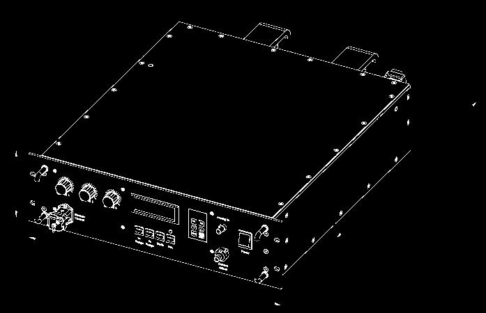
109 U 591 mm 19" Standard 19 Plug- module approx. 40 kg 3U

 Frequency 50 or 60Hz")
 dependg on power Safety / Construction acc. to EN 60950-1 / EN 50178 EMI acc.")
110 Thyristor Controlled 1 or 3-Phase Input from 500W to 500kW / Power Supplies & Battery Chargers put voltage: 115 / 230V, sgle phase, 50 / 60Hz or 200/ 400/ 480/ 690V, 3-phase, 50 / 60Hz voltage: 12 / 24 / 48 / 60 / 72 / 110 / 220 / 360V current: up to 3250A power: 500W - 500kW Features Robust design High reliable 6-pulse performance Optional: 10% put current distortion for 12-pulse charger Turn Key solution Constant current & voltage operation Industrial grade components High level of humidity protection Concise & clear dication panel Specifications Input Voltage range nomal voltage ±10% (other voltage upon request) Frequency 50 or 60Hz ±5% Protection by fuse General Efficiency - Series QE - Series QD Operatg temperature Humidity Altitude Audible noise 80 90% 82 92% for models <48V 85 95% for models 48V 10 to +40 C, optional up to +65 C up to 95 % RH, non-condensg up to 1000 m asl natural convection or ternal fans 50-70dB (A) dependg on power Safety / Construction acc. to EN / EN EMI acc. to EN , class A Enclosure - Protection category - Color IP20 acc. to EN 60529, optional up to IP55 RAL7035, others upon request Transformer acc. to IEC 76 / IEC14 / EN / DIN VDE 0532 Voltage adjustable from % of U nom (other voltage upon request) Le regulation (±10%) ± 0.5% Load regulation (10-90%) ± 1% Dynamic load ( %) ± 10% typical Ripple 5% rms with battery, optional: < 2% rms or 2mV frequency weighted Current electronic current limitation adjustable from % of I nom Overload protection short circuit protected by fuse and electronic current limitation Chargg characteristic IU acc. to DIN for Pb batteries DIN for NiCd batteries Chargg voltage - float - equalize - boost (manual activated) V/ cell for Pb batteries / 1.4V / cell for NiCd batteries V / cell for Pb batteries / 1.55V / cell for NiCd batteries 2.7V / cell for Pb batteries / 1.7V 7 cell for NiCd batteries

 automatic selection of chargg")
 analogue or micro-processor-controlled put/ put voltage battery circuit ground sulation failure over")

111 Options Input MCB, MCCB or isolator rush current limitg 690V put parallel or redundant operation 12-pulse performance filterg up to 0.1% pp (correspondg to 0.035% rms) or 2mV frequency weighted voltage stabilization Control (details see page 123) IU characteristic acc. to DIN and manual selection of chargg characteristic (float / equalize / boost) automatic selection of chargg characteristic with timer temperature compensated chargg voltage Battery MCB, MCCB or isolator deep discharge protection Monitorg (details see page 123) analogue or micro-processor-controlled put/ put voltage battery circuit ground sulation failure over temperature Interface Card CAN Bus MOD Bus Mechanics / environment: enclosures, IP20 up to IP55, for charger and / or batteries analogue or digital meters operatg temperature up to +65 C tropical protection earthquake-proof verm-proof Converters / Inverters switchmode / converters from 100W to 40kW switchmode / verters, frequency converters and static switches from 200 VA to 45k VA
112 Thyristor Controlled Series QE with sgle phase put, 500W-5kW Model designation (example): QE 24 / 20 Q1 F1 L1 N sgle phase put nomal put voltage [V] max. put current [A] T1 THYRISTOR CONTROL L1 V1 V2 C1 V3 V4 R5 F6 A V QE - Series 1-phase thyristor-controlled rectifiers, 500W-5kW nomal put voltage 12V 24V 48V 60V 110V 220V 360V max. put current from 0 to 130A L- - BATTERY R7 L+ + BATTERY F31 F32 1L- 1L+ -LOAD nomal put voltage approx. le enclosure 12 V current size 24 V 48 V 60 V 110 V 220 V 1) 2) max. put current [A] [A] R3 R4 R5 R5+ approx. weight 3) [kg] ) Larger size may be required for optional equipment. 2) Le current is referred to nomal put voltage of 230 V. 3) Weight is referred to thyristor-controlled rectifier on a mountg plate with enclosure. Enclosures wall-mounted weight height width depth enclosure (empty) designation [kg] dimensions [mm] R R R4 17 R R4T R R floor-mounted enclosure designation weight (empty) [kg] height* width depth dimensions [mm] R R R R R R R *) The height of the base frame, elevated roof and suspension eyes is to be added, if needed.
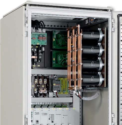
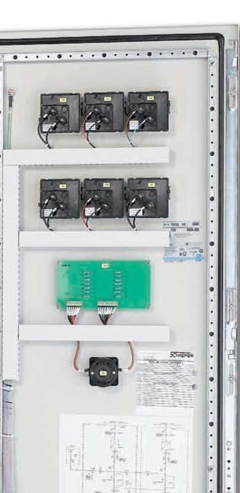
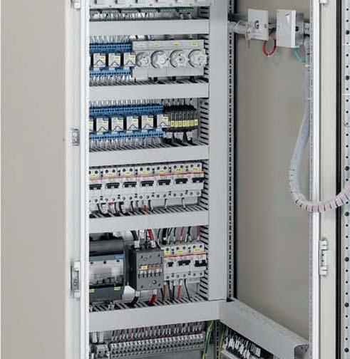
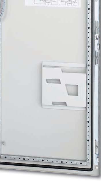
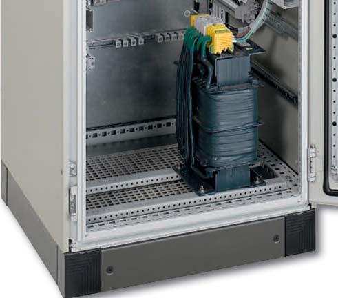
113
114 Thyristor Controlled Series QD with 3-phase put, 1-500kW F1-F3 Q1 L1 L2 L3 Model designation (example): QD 60 / 32 three phases put nomal put voltage [V] max. put current [A] T1 6-pulse THYRISTOR CONTROL L1 V1 V2 V3 C1 V4 V5 V6 R5 F6 A V QD - Series 3-phase thyristor-controlled rectifiers, 1-500kW nomal put voltage 24V 48V 60V 110V 220V 360V max. put current from 0 to 3250A L- - BATTERY R7 L+ + BATTERY F31 F32 1L- 1L+ -LOAD nomal put voltage approx. le enclosure 24 V 48 V 60 V 110 V 220 V current size 1) 2) max. put current [A] [A] approx. weight 3) [kg] R R R R R R R R R R x R x R x R x R ) Larger size may be required for optional equipment. Enclosures see page ) Le current is referred to nomal put voltage of 3 x 400 V. 3) Weight is referred to thyristor-controlled rectifier on a mountg plate with enclosure.


115

116 Options & Accessories for Switch Mode Units Schaefer offers the dustry s most complete range of put and put voltages, combed with a selection of package style, mountg solutions, options for put and put as well as various possibilities of programmg & monitorg. Configuration of model designation: Add the designation of options to the type number of the power supply module, e.g. C 3674-w-dr-eu1. Input i ie rush current limitg A thermistor is connected series with the put les which changes its resistance from high to low when it gets hot. It does not reduce the surge current if the put power is terrupted for a short period of time not allowg the thermistor to cool down. Thermistors are fitted as standard to all mas put models except for 1-phase put of models > 2.5 kw. Thermistors are available up to 45A. For higher put current an electronic rush current limitation can be offered. electronic rush current limitg An electronic circuit limits the high rush current caused by built- capacitors. Switchon time may crease to 5s. This is realized by a series pass transistor or dependg on the put voltage by thyristor softstart. IN IN time delayed OUT OUT sd reverse polarity protection for put by series diode A series diode protects the module agast put voltage of wrong polarity. However, this also causes extra losses and reduces the overall efficiency. calculation formula: I Diode = 2 x P max / U m IN OUT

117 ad reverse polarity protection for put by anti parallel diode To avoid the power losses a diode is provided with opposite polarity parallel to the put blowg an ternal or external fuse if the module is connected to a supply of wrong polarity. calculation formula: I Diode = 2 x P max / U m IN OUT au auto-rangg For standard dual put models the range of 115 / 230 V is to be selected by connectg the put le to different ps on the connector. With auto-rangg the unit senses the put voltage and provides automatically the correct connection. L 115V or 230V OUT N
118 Options & Accessories for Switch Mode Units Parallel / redundant operation for put (details see page 125/126) dd decouplg diode A series diode built to the units put allows parallelg of 2 or more units for redundancy or higher power or battery chargg. For control purposes the anode of the diode is also available at the put connector. It cannot be loaded 0.5A. The sense signal is taken partially from the anode and partially from the load/cathode of the decouplg diode. This guarantees startg and operatg under all conditions, but it also effects the regulation accuracy of 2%. In this way it gives a load sharg of 15-30% between the paralleled units. IN + OUT - cs active current sharg An additional control circuit provides active current sharg via an terconnectg wire between converters that operate parallel. The put les of the converters have to be star pot connection. IN CS + OUT - IN CS csi current sharg terrupt ( cs cluded) csi will effect the removal of the cs signal from the load voltage common connection. Should there be an stance where a unit is not supplyg the load, then the effect of its current sharg signal is removed, and the load voltage is unaffected by this condition. In terms of calibration the same criteria follow as for parallel operation. IN CSI + OUT - IN CSI icsi current sharg terrupt ( csi cluded), galvanically isolated The clusion of csi (current sharg terrupt) and the galvanic isolation is the optimum set up for systems with high power or high currents, were the voltage drop on the power wirg could fluence the cs signal. IN CSI IV OUT IN CSI IV ma master / slave operation (avalaible for series 6xxx) Master / Slave terface permits the parallel function of identical modules to crease the put power capapcity, shared by current control with any dynamic reduction performance. IN MS current regulation OUT IN SL current regulation regulation Parallel / redundant operation for put red verter parallel operation: for series IT5xxx For redundant operation or for creased put power, two verters of the IT5xxx series can be switched together. If one verter fails, the ternal contactor will be switched off and the put power of one verter is still available. IN current current sharg OUT L N IN current current sharg OUT General formation The number of options per module may be restricted due to limitation of space side the module or due to a limited number of connector ps. Potentiometers or terface cards may be supplied separately for stallation side of the module.
119 Inhibit h1 hibit by external closg contact, signal referred to put The operation of the unit is hibited when a voltage signal is applied reference to the negative le of the put. This can also be used combation with a thermal trip, which shuts the unit down. IN INH primary control OUT h2 hibit by voltage signal, signal referred to put Operation of the unit is hibited if a voltage signal (5V / 10mA) is applied reference to the negative le of the put. IN secondary sec. control control INH h3 hibit by closg contact, signal referred to put The operation of the unit is hibited when a voltage signal is applied reference to the negative le of the put. This can also be used combation with a thermal trip, which shuts the unit down. Please note: Only relevant solution for verters. IN secondary sec. control control INH Automatic reduction of current limitg rco reducg current limitg at over temperature A circuit reduces the current limitg level at higher temperature (to be specified). Please note: Option is avalaible for series 48xx with ZVS topology and for high power converter modules (see page 49). IN secondary sec. RCO OUT control put protection rd reverse polarity protection for put by reverse diode with external fuse IN OUT
120 Options & Accessories for Switch Mode Units Signals pr put voltage supervision (power ok) cl. relay contacts A logic signal is given if the put voltage ( or ) drops below the specified limit. In put models the rectified put voltage is sensed so that a power fail alarm can be avoided if at light load mas power returns before the put capacitors are substantially discharged. A relay contact is provided for failure dication. IN OUT dr put voltage supervision ( ok) cl. relay contacts A logic signal is given if the put voltage is below the specified limit. A relay contact is provided for failure dication. ok level: 5V put: 4,75V all other voltages: 90% of adjusted voltage IN + OUT - cf charger / converter fail supervision cl. relay contacts A logic signal is given if the put voltage, the auxiliary voltage of the primary side and the current of the primary side exceed or go below a specified range. A relay contact is provided for failure dication. IN primary control circuit supervision OUT ac ok for verter cludg relay contacts A logic signal is given if the put voltage of an verter is below the specified limit. A relay contact is provided for failure dication. L IN N General formation The number of options per module may be restricted due to limitation of space side the module or due to a limited number of connector ps. Potentiometers or terface cards may be supplied separately for stallation side of the module.
121 Programmg Converter Programmg programmg of put voltage from 0 to 100 % eu1 by external signal, 0 10 V eu2 by external signal, 4 20 ma eu3 by 270 potentiometer eu4 by 10 turn potentiometer programmg of put current from 0 to 100 % ei1 by external signal, 0 10 V ei2 by external signal, 4 20 ma ei3 by 270 potentiometer ei4 by 10 turn potentiometer iso isolatg amplifier for programmg Programmg signal is galvanically isolated from any potentials of the power supply. programmg via rs RS232 (external) can CAN Bus (external) Charger Programmg temperature features tc temperature compensated chargg voltage (sensor not cluded) ts1 temperature sensor not terchangeable due to fixed resistor values ts2 temperature sensor terchangeable, IC controlled chargg characteristics ch1 External card: automatic and manual selection of chargg characteristic (float/ equalized boost charge) with timer (delayed return to normal operation), cludg aux. supply and options tc and ts1 ch2 External card: consistg of option ch1 plus: Battery current limitation & battery shunt ch3 External card: consistg of option ch2 plus: CAN-Busterface & programmable parameters Monitorg Converter / Charger Monitorg monitorg of put voltage from 0 to 100 % mu1 by external signal, 0 10 V mu2 by external signal, 4 20 ma monitorg of put current from 0 to 100 % mi1 by external signal, 0 10 V mi2 by external signal, 4 20 ma iso isolatg amplifier for monitorg Monitorg signal is galvanically isolated from any potentials of the power supply. monitorg via rs RS232 (external) can CAN Bus (external)


122 Options & Accessories for Switch Mode Units Mechanics As standard, all of the modules are designed and manufactured for sertion to 19 sub-racks. Higher power modules are already constructed 19 format. Optionally, 19 sub-racks are available and can be configured as 3U or 6U allowg any mix of units and can be upgraded accordance to the customers requirements, e.g. matg connectors wired to a termal block fuses or circuit breakers hot swappable configuration upon request analog or digital meters switches fans filters decouplg diodes provisions for keyg the modules to ensure module / slot designation 19 Sub-Racks 3U = mm 19" = 483 mm 84TE = mm 6U = 266 mm 19" = 483 mm 84TE = mm 6U = 266 mm 19" = 483 mm 2TE = 10 mm 84TE = mm 3U = mm 3U = mm w wall mount Modules, which have the wall mount option, are typically fixed to a structure or with a cabet. Dependg on the size of the module, this may be done with a flat or angled plate (see photo). The load connections are typically through a termal block. Should the application not require a pluggable module / rack solution, wall mountg presents an alternative option for the customer to choose from. cha chassis mount Module is designed for stallation to a structure or with a cabet. Screw type matg connectors are supplied with the module. Due to the limited number of connector ps this option is not available for modules with dual put. Option is avalaible for currents up to 60. d DIN rail mount Module is designed for DIN rail mountg to a structure or with a cabet. Screw type matg connectors are supplied with the module. Due to the limited number of connector ps this option is not available for modules with dual put. Option is avalaible for currents up to 60.

123 Environment t c ms tropical protection The unit is given additional protection by a heavy coat of varnish on the prted circuit board(s) and on components to achieve 99% RH, non condensg. extended temperature range The circuit is designed and tested for operation at an ambient temperature as low as 40 C. creased mechanical strength Screws are secured with Loctite and heavy components are fastened by ties and / or glue. Modules with the ms are build acc. to EN regardg shock and vibration.


124 Options & Accessories for Switch Mode & Thyristor-Controlled Systems Control & Monitorg TC 01 Control function analogue or micro-processor-controlled supervision: put voltage put voltage battery circuit ground sulation failure over temperature UC 03 Inhanced controller function The UC 03 unit controls and supervises the optimum chargg of a battery, up to an entire UPS system. A battery chargg a basic way, with a switch mode / or / Charger, is shown the followg figure. Mas Power UC 03-xx V ref Charger V o/p V = Battery current Battery voltage Battery The charger put voltage is regulated side the charger accordg to the put Vref signal. The ga factor between Vref and Vo/p is defed the Specification of the Charger. The charger current limitation is also a function of the charger. The reference values, limitations and monitorg levels for chargg a battery (ies) are configurable the UC 03. The chargg of the battery occurs accordg to the current / voltage characteristics, i.e. the battery is loaded current limitation, until the appropriate voltage is reached. The followg workg conditions are processed by the UC 03: a. Float Charge conforms to the recommended permanent voltage to hold the battery with a completely charged state. b. Equalize or Automatic Boost Charge: To charge the battery after a partial or deep discharge as quickly as possible, an creased voltage is provided. This mode is activated automatically via different functions, or manually via the front panel button. c. Manual Boost Charge: dependently adjustable voltage, to regenerate an aged battery. In all three workg conditions the maximum battery charge current is limited.


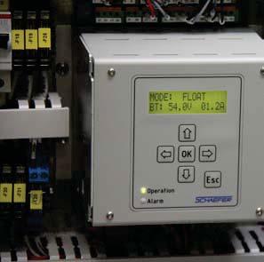
125

126 Technical Notes Operational Characteristics The followg technical notes conta important formation ab various operatg possibilities and circuitries as well as structions that should be followed durg stallation etc. For further formation please contact the SCHAEFR Team. Parallel / Redundant System 125 or put 127 put 128 put 129 put voltage stabilization 130 Mountg & Installation 131 Connectors 132 Basic Topologies 133 Parallel / Redundant System Parallel operation Sgle put modules of the same voltage / power ratg can operate parallel under specific conditions. The put voltage can be carefully adjusted to be near identical. When there is sufficient loadg on the combed put, all units will be active and supply the load. The load demand must be significant enough for the multiple units to deliver put current. Redundant operation The clusion of the option dd (decouplg diode) on the put of the units will permit parallel operation, where the ability to provide put from one unit will not have a negative effect on the load provision. The decouplg diode will also result a load regulation value, which, as a percentage of the put voltage, will be unit / put dependent. In terms of calibration the same criteria follow as for parallel operation. or = or or or = = =
 on the puts.")
127 Balanced current operation The clusion of the option cs (current sharg) allows for parallel operation with a significant degree of current balancg. The communication between the units allows for a voltage settg correction, which turn shall equate to an automatic current sharg (balancg) on the puts. The tolerance of such balancg is module dependent. In terms of calibration the same criteria follow as for parallel operation. Redundant balanced operation The clusion of both, the cs and dd option results an optimized balanced current provision while beg de-coupled from each other. A connected module, who is not supplyg an put voltage, will fluence the load voltage. The voltage may be reduced by up to 7 %. In terms of calibration the same criteria follow as for parallel operation. or = CS or = CS or = CS or = CS CS CS Fault tolerant operation The clusion of csi (current sharg terrupt), cs and dd is the optimum set up for a fault tolerant application. csi will effect the removal of the cs signal from the load voltage common connection. Should there be an stance where a unit is not supplyg the load, then the effect of its current sharg signal is removed, and the load voltage is unaffected by this condition. In terms of calibration the same criteria follow as for parallel operation. or CSi = CS or CSi = CS CS
128 Technical Notes Operational Characteristics or put rush current When the module is connected to the put power, the primary capacitors will be charged by a high current pulse. The magnitude of this pulse depends maly on the put supply system. With a thermistor (temperature dependent resistor) series with the put, this current pulse can be reduced, as the thermistor has a relatively high value of resistance as long as it is cold. This resistance becomes very low as the thermistor heats up. If the put power is terrupted for a Power factor correction (PFC) Power supplies draw le current pulses from the put supply. Should it be required, a PFC will tegrate these pulses to be both, effectively susoidal shape, and phase with Spike suppression High put voltage spikes generated the supply system that could disturb operation of the unit or cause damage will be Input under and over voltage turn off The put voltage range of the unit is defed as the voltage limits at which it will operate. Should the put be reduced to a specific voltage, the unit will turn off by switchg off the power circuit. The same applies to an crease the put Thermal shutdown with auto restart The higher power Schaefer modules are fitted with a thermal shutdown. In the event of a temperature rise above a preset value, the unit will turn off. This safety feature will then Temperature derated load It is the responsibility of the client to reduce the loadg of the Schaefer product with respect to the temperature (derated load: 2.5 % / C from +55 C operatg temperature). The Efficiency The optimum efficiency is obtaed through a high put voltage measured agast a high put voltage at maximum short period of time not allowg the thermistor to cool down, and the primary capacitors are discharged, the current limitation function of the thermistor will not be effective. The thermistor is standard on mas put models up to 45 put current. For higher put current there are two further alternatives available: Schaefer PFC or an electronic current limitation. the put supply. The result of this tegration, be it active or passive, is the reduction of the harmonic distortion and allows a more effective loadg of the put source. absorbed by a varistor across the put les. voltage. Once a preset value is reached then the power circuit will be switched off. It must be considered that the switchg off of the power circuit does not mean a removal of the put circuit from the power supply. rema active until the pot of temperature measurement has reduced significantly. The time duration for this to be reached is dependent upon the environment and level of coolg. maximum operatg temperature of +75 C must lead to the unit beg switched off. power ratg.


129 put Soft start The application of the put power permits the unit to generate a secondary put. The switchg on of the primary power circuit is controlled and gradually creased to allow No load operation Sgle put converters require no mimum load for operation with tolerance. Multi put converters require Short circuit protection The ma put of a converter will be immune agast a momentary or contuous short circuit. The secondary current limitation will not permit the sustaed put current to be higher than the calibrated settg, and it will actively reduce the put voltage accordance to the overload. The Over voltage protection (OVP) The ma put voltage is measured, either ternally or through sense leads. This measured value is compared agast a calibrated value. When the calibrated value has been reached, this circuit turns off the primary power circuit. Once the measured value has reduced below the calibrated a controlled chargg of the secondary capacitors. The time duration for the secondary capacitors to be charged is defed as the soft start. the ma put be loaded. Semi-regulated auxiliary puts may also require a mimum load to be applied. removal of the overload / short circuit will result the put voltage beg creased to the calibrated value. Regulated auxiliary puts will also reduce the put voltage / current accordance to their overloadg. The characteristic may vary accordg to the circuit employed. value, the primary power circuit is permitted, once aga, to be activated. The high power units have an additional feature, which will shut down the primary power circuit after a contued OVP operation. The put power must be re-cycled order to remove the unit from shut down. voltage adjustment [V] Over voltage protection [V] Sense leads Through the use of sense leads, an put voltage may be regulated to a pot side of the unit. The sense leads should be connected to the power connection at the pot of load under regard of polarity. There should be a non-terruptible connection between sense and load pots. Interruption may lead to damage or the activation of the OVP circuit. The units, which have sense leads, have the ability to regulate to a higher voltage at the put connection. This crease is largely dependent upon the unit. The details may be found the respective unit specification. Parallel operation with sense leads allows a common pot for the units to regulate their voltages to. Units whose put voltage has been calibrated to be near identical will now be able to supply a common load. De-coupled puts will be sensed both, before and after the decouplg diodes, which turn will lead to an put voltage regulation, specifi c to load and unit. Sense leads are typically employed with a decoupled put voltage of less than 40. The current sharg option will effectively override the sense lead put voltage settg, but the pot at which the put voltage is regulated, will be the pot of sense lead connection.
130 Technical Notes Operational Characteristics put Soft start The application of the put power permits the unit to generate an put. The put power creases learly until it reaches its calibrated value. This delay from itial put generation until the nomal value is defed as the soft start. No load operation Inverters require no mimum load for operation with tolerance. Short circuit protection The verter current limitation circuit provides a protection agast an external short circuit. Due to the need for crest factor and pulse power requirement many applications, the current limitation permits twice the nomal put current to be extracted for up to 1 second. The current limitation will then be reduced to typically 105% of the nomal value. Should the overloadg persist, and the put voltage reduce to less than 20% of nomal, then the unit will perceive an overload condition and turn off. Recyclg the put voltage will remove this latched off condition. Crest factor The ability of an verter to deliver to a load an rush current is related to the crest factor. The crest factor is the ratio Over voltage protection (OVP) The high power units have this feature. It will shut down the primary power circuit after a contued OVP operation. The put power must be re-cycled order to remove the unit from shut down. The put voltage is measured ternally. This measured value is compared agast a reference value. between the nomal and the peak current. When the reference value has been reached, this circuit turns off the power circuit. Once the measured value has reduced below the reference value the power circuit is once aga permitted to be activated. Sense leads Sense leads are ternally connected all standard configurations. Harmonic distortion The generated verter put is designed to follow a true se wave signal. Deviation from this se wave is measured as distortion. The level of deviation is defed as harmonic distortion. The total harmonic distortion THD is the relationship between the harmonic and fundamental wave forms. Surge power The put may facilitate the put load through its ability to provide more then the nomal current for up to 1 second. Power factor The put may facilitate complex or other loads, through its ability to provide a phase shifted put current at nomal power ratg. This is once aga due to the ability to provide more than the nomal put current for a limited period of time.

131 put voltage stabilization The put voltage of a battery charger with parallel connected batteries varies substantially with the chargg condition of the battery. For many applications, however, the load circuit requires a more stabilized voltage which can be accomplished by: Voltage droppg diodes beg terconnected between battery and load, reduce the voltage to a value suitable for the load. They are short-circuited by one or more contactors only if a partial reduction or no voltage reduction is required. A control circuit senses the battery voltage and energizes the contactors. Voltage droppg diodes cause substantial power losses as the excess voltage is absorbed by the diodes. However, due to simplicity, this method is frequently used, especially if the voltage reduction is needed only durg the short periods of high-rate chargg. put battery charger K2 control circuit for K1 and K2 K1 - + battery -load Switchmode step-up converters are / converters supplied from the battery with the put connected series to the battery. They present a very economical solution as they only add voltage when the battery is discharged. Details see page 47/ 83. step-up converter (long) cable to load + battery charger + - sense leads load -
132 AIR FLOW Technical Notes Mountg & Installation Mountg Air flow Airflow to the power supply is preferred to be filtered, below 55 C, an airflow resistivity (pressure drop) of below 20kPa and is required to comply with the EN60950 pollution category II. Diffused thermal energy is required to be exhausted and displaced by air as detailed above. Thermal management is required where the air provided to a power supply complies with the power supply s design parameters. The use of fans requires the crease airflow rate to a mimum of 120m 3 /h (correspondg to 70 cfm). The airflow resistivity and respective pressure drop should be considered when the fan is required. Direction of air flow Typically, Schaefer Modules and systems are cooled through air supply enterg below and exitg above, with the exception of models of series C/B 5100, 5200, 5300, 5400, 6400 and 6600 whose airflow is from front to back. Custom design also offers lateral coolg. Such details are however, project specific. AIR FLOW AIR FLOW Cabet To enhance a module / system, a cabet may be employed. - This may be required to fulfil the creased IP / NEMA ratg, due to a negative effect of the environment on the solution. - Specifically, an unclean, saturated, corrosive or otherwise aggressive air quality it may be required to employ a cabet combation with features such as hermetical closure and air exchange amongst others. - The enclosure must be capable of sustag the weight of the modules, specifically if module support rails are used. - Stationary cabets should be fastened to the ground. - The centre of gravity must be as low as possible with portable systems. Transportation of module The grips on the front of the modules are to assist module sertion to a sub-rack, and not for supportg the weight of the module. Wall mount / chassis mount Modules with a mountg plate or angle are designed for tegration to the host equipment. They are not for employment side of an enclosure. Installation Input fuse An put fuse, ternal or external, should be selected with a slow burn characteristic. Sense leads - The distance between the load connection and the module / system may result a voltage drop between the put and the load connection. To compensate for a limited value of such a voltage drop, sense leads can be connected to the load under regard of polarity. The sense leads determe the pot to which the voltage regulates. As the sense leads carry very low current, they are susceptible to noise pick up. Therefore, it is recommended that they are tertwed and if necessary shielded. - -S +S + - When the remote sense facility is not used, sense lks must be made at the put termals. If the sense lks are left open, the put voltage may rise causg the OVP circuit to be activated. - LOAD +
: 3100 V rms Contact resistance: 8 mω Performance accordg to: IEC 60603-2 / DIN 41612 High Current Female Connector Number of contacts: 2 Contacts: Bolts")
133 Connectors H15 Female Connector Number of contacts: 15 Contacts: Fastons or screw termals Operatg current at +20 C: 15 A Operatg temperature: 55 to +125 C Test voltage (contact to contact): 3100 V rms Test voltage (contact to ground): 3100 V rms Contact resistance: 8 mω Performance accordg to: IEC / DIN High Current Female Connector Number of contacts: 2 Contacts: Bolts with 8 mm diameter for termal lugs M8 Operatg current at +20 C: 170 A Operatg temperature: 55 to +125 C Test voltage (contact to contact): 500 V rms Test voltage (contact to ground): 2500 V rms Contact resistance: 0.06 mω Dimensions (H x W x D): 118 x 35 x 85 mm Performance accordg to: IEC / DIN F24H7 Female Connector Number of contacts: 24 / 7 Contacts: solder ps / fastons Operatg current at +20 C: 6 / 15 A Operatg temperature: 55 to +125 C Test voltage (contact to contact): 1550 / 3100 Vrms Test voltage (contact to ground): 2500 / 3100 Vrms Contact resistance: 15 / 8 mω Performance accordg to: IEC / DIN F48 Female Connector Number of contacts: 48 Contacts: solder ps Operatg current at +20 C: 6 A Operatg temperature: 55 to +125 C Test voltage (contact to contact): 1550 V rms Test voltage (contact to ground): 2500 V rms Contact resistance: 15 mω Performance accordg to: IEC / DIN 41612
134 Technical Notes Basic Topologies There are various circuit topologies and the selection depends on the requirements, such as low or high put voltage, low or high put voltage, sgle or multi put, power ratg. The followg circuits present our common concepts of power conversion. Push Pull Converter The push pull converter is often used for applications with low put voltage. The switchg transistors are alternately conductg with variable pulse-width. At the secondary side, after rectification and filterg, the put voltage is sensed and compared with a reference. The error signal controls via an opto-coupler the primary circuit. + put - RFI filter I-lim. prim.control optocouplers I-lim. sec.control ripple filter OVP + put - + sense - Half Bridge Converter The followg circuit shows, as an example, a converter with dual put a half bridge connection. With the put voltage supplied to the 230 V termal, the rectifier circuit is a standard bridge connection; supplied to the 115 V termal the rectifier circuit functions as a voltage doubler circuit. RFI filter 115V 230V 0V put - rect. I-lim. ripple filter I-lim. OVP + ma put - prim.control optocouplers sec.control + sense - / Inverter The diagram beside shows the circuit of an verter. The put voltage is transformed by the power transistors T1-T4 with the parallel connected verse diodes D1-D4 a pulsewidth modulated square wave voltage. The choke with the wdgs LI and LII tegrates this voltage, and at the capacitor C a susoidal put voltage is available. The power transistors are controlled via opto-coupler such a way that not both transistors of one branch are conductg at the same time. The put voltage is sensed and compared with a reference signal generatg the firg pulses for the power transistors. The put current is measured via shunt R1 and limited through the control circuit. Isolation between put and put and voltage transformation can either be provided by a converter connected to the put of an verter or by a transformer connected to the put of an verter. Inverter put D1 D2 T1 T2 optocoupler optocoupler control + PWM voltage sense current sense R2 LI C LII R1 Inverter put T3 T4 D3 D4
 beg controlled by the driver and protective circuits.")
135 Full Bridge Converter with Zero Voltage Switchg (ZVS) For the higher power modules presented from page 46 to 67 the primary circuit is performed as a full bridge connection with four switchg transistors (IGBTs) beg controlled by the driver and protective circuits. The special mode of drivg the IGBTs conjunction with the resonant choke and the symmetrical capacitor allows for zero voltage switchg which improves the efficiency and reduces the switchg noise. The put can be designed for both, or. At the secondary side of the transformer the voltage is rectified and filtered. Then the put voltage is sensed and compared with a reference, and the error signal controls via opto-coupler the switchg transistors on the primary side. For over voltage protection the OVP circuit senses the put voltage and turns off the switchg transistors if a certa level is reached. The circuit automatically returns to operation but is repeatedly switched off and turned on aga if the over voltage condition is still present. If the unit does not return to normal operation with a short period of time, it will then be switched off. For current limitg the signal sensed by the LEM transformer starts to reduce the put voltage if the current exceeds a certa limit. + RFI filter ripple filter + IGBTs put resonant choke put - symmetrical capacitor LEM transformer OVP - + sense optocoupler control - Driver and protective circuits for IGBTs


136 Design Solutions Customized Systems The distction the market of power supplies is achieved by beg customer orientated, the unique variety of products available and the high level of flexibility to customer specific requirements as well as the modification of standard equipment for small and large quantities. Customization Immediate proximity also generates the free flowg formation path, which is the production and development areas, along with the testg and customer support areas beg all under the same roof. This enhances the SCHAEFER Teams ability to react to exactg demands with ease. Fruits of this labour are to be seen through the World, a variety of fields such as: Rail & Automotive Industry Power Generation Plants Oil & Gas Industry Chemical Industry Industrial Automation Military Industry Buildg Security Integrated Airport Solutions Be they on shore or off shore, stationary or mobile, land, air or mare based. A system component or complete system, environmentally Hazardous area 1, corrosive or simply Industrial, there is a SCHAEFER Power Solution to fit the parameters. Welcomg the challenge, the SCHAEFER Team offers the highest quality engeerg designed and manufactured Germany.


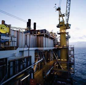


137 made Germany Interested new projects? Just scan this QR-Code!


138 Design Solutions Rail & Automotive 40kW On-board Power Supply System Multi put/ Multi put system Hermetically sealed enclosure Controlled air management Battery charger & Bus supply Challengg environmental specifications Engeered for high degree of shock & vibration Self-protectg, autonomous assessment of thermal and electrical parameters 8kVA Rollg Stock Mounted Inverter, IP66 Client specific terface connection Anchored to the RAIL Car floor 600mm 600mm foot prt Impervious to both impulses and spikes across the put, this module delivers the full put range with a crest factor of 3, up to +75 C environmental temperature Full power ability, across a phase shifted load, capacitive & ductive load tolerant of ± 0.7cos 300kW ultra fast chargg station for E-Busses Modular and expandable power capability N+1 redundancy concept fully redundant and fault tolerant Easy system expandability up to 1MW by addg additional fully wired 100kW enclosures voltages available up to 1000 V Control and adjustability of electrical parameter Additional customised options CAN/ Modbus Interface


139 Power Generation Coolant System Control for Reactor KTA 3507 certified Integrated switch mode Power Supply Reactor Core temperature evaluation High level of reliability, redundant fault tolerant capability 19 designed Rack mechanical solution Enhanced mechanical design Programmable put parameters through Client Interface Power Supply Modules for Substations Fault tolerant power configuration Automated terrupt free by-pass operation Stabilized load feed Expandable to multiple redundant design Hot-pluggable Multiple mechanical solutions and styles N+2 UPS System Configured both dual redundant & fault tolerant Supplied from multiple dependent and an source Both automatically and manually operational by-pass system Integrated & isolated by-pass The dication panel reflects the operational status, while multiple stage monitorg is both locally and remotely communicated.


140 Design Solutions Oil & Gas Industry Subsea Power Supply Module based on a C3700 standard unit Extreme Environmental Challenges Wide range of put supply Robust heat sk design to tegrate to the titanium pipe / tube Enhanced mechanical tegration Over-temperature alarm The unit is given additional protection by heavy coat of varnish on the prted circuit board and on the components. 360kW expandable power supply system Meral exploration on vessel: Assistg the oil dustries the search of oil reserves offshore via electromagnetic streamer process Liquid cooled current source up to 2500 A with high dynamic regulation properties Modular, N+1 redundant concept via 30 kw sgle modules with Master/ Slave configuration Power Supply for Off-shore Oil & Gas Industry 15kW liquid cooled power supply system Dimensions: 5U mm deep solution (H x W x D) Redundant fault tolerant capability High efficiency through ZVS topology Assistg the dustry the search for meral resources


 Robust")


141 Military Industry On-board Military UPS Integrated Inverter, Static Switch and Battery Charger Dimensions: 6U mm deep solution (H x W x D) Robust and reliable design Digital voltmeter display for put (battery voltage) on front plate Push button for Latch Reset Common alarm with relay contact Digital voltmeter display for put (battery voltage) on front plate On-board 3-D Radar Power Supply / converter with fan coolg High level of reliability, Redundant fault tolerant capability Environmental adapted to 97% non condensg humidity Power Factor correction for three-phase put mimizg the load requirement of generator Client specific mechanical & electrical design with special heat sks Integrated combed solution 5kW Modules ensurg a high power density Flexible orientation Capable of populatg a 5U RK with three units Capable of populatg a 3U RK with two units Engeered for high degree of shock & vibration


142 Design Solutions Buildg Security N+1 UPS System Configured as a redundant & fault tolerant solution Supplied from multiple dependent sources Both automatically and manually operational put characteristic Compliant with exactg environmental standards to ensure a highly reliable load power supply for critical applications 7kW Power Supply for Security Checkpots Airport application Wide put voltage range: V, 3-phase High put voltage: 600V via temperature controlled fans Industrial grade components 4U plug- module Worlds largest water founta at Burj Khalifa, Dubai Chargg the tegral water, light and sound show of the founta Turn-key customised design: UPS systems with a cabet clusive battery equipment as well as various SMPS systems Supervision and diagnostic software CAN/Ethernet terface for control and monitorg of electrical parameters


143 Industrial Automation kW Liquid cooled Power Supply For semiconductor manufacturg dustry Highly demandg environment Extreme load variations Transfer of thermal energy to a fluid for heat exchange re-capture Programmable put parameters through Client Interface / Converter for Robotics Power Supply Wide put voltage range: V Multi put parameters Natural convection Remote on / off (hibit) CAN-Bus terface High level of reliability, redundant fault tolerant capability Digital controlled generator for Erodg Steel Rolls Electrical Discharge Generator with adjustable power source: 0-30A Synchronized put at U=300V with adjustable frequency the range of 200Hz to 300KHz Pluggable system, stallation on water heat sks via pressure rails Communication via EtherCat (PC-generator)


 voltage required,")

")


144 Design Solutions Demandg Markets 4kW Inverter System for Aircraft Mas Simulation Ground equipment for mas simulation on the Eurofighter Converter for 400Hz mas simulation selection, 3-phase or 3 dividual voltages Each put is dividually programmable via RS232 terface voltage and frequency 400Hz Input Frequency 1kW N+1 Tsunami Warng System Sub sea power supply Input voltage 1200V up to 2450V (nomal) voltage required, 380V ( V calibration range) Galvanic isolation High level of reliability Safety Valve For stallation explosive environments (hazardous area 1) Allowg the failure of a sgle power supply, not affectg the controlled put The overall power supply unit is housed with a certified Exd enclosure An Exe enclosure beg attached to the Exd enclosure contas all termations, operator dications and switches


145 If you are lost on the moon, marooned the ocean or just dealg with pollution, Schaefer has the POWER to fd the solution.
146 Notes
147


 4-204 5832")
148 SCHÄFER Elektronik GmbH Oststrasse O t tras se 17, Gamshurst s st Achern h r Germany G a y Phone o e (0) ) Fax (0) ) mail@schaeferpower.de m aefe er SCHAEFER Inc. 45 Sh Street Hopkton, n, MA USA Phone Fax sales@schaeferpower.com s@ sc efer er r.co com SCHAEFER GmbH Middle East 5EA-528, 528, Dubai Airport rt Free e Zone P.O.Box: , 9, Dubai UAE Phone (+971) Fax (+971) mail@schaeferpower-me.com ae er-m e. com edition ME13 For more formation just scan this QR-Code!
Power Conversion Systems 2005/2006. Schaefer the Power to make it happen.
 Power Conversion Systems 2005/2006 Schaefer the Power to make it happen. Company profile workforce experience customer orientation flexibility reliability Schaefer Elektronik, founded in 1969, has grown
Power Conversion Systems. SCHAEFER International. Switchmode Power Supplies, Chargers & Inverters. Thyristor-controlled Power Supplies & Chargers
 SCHAEFER International Power Conversion Systems Innovation made in Germany SCHÄFER Elektronik GmbH Oststrasse 17, Gamshurst 77855 Achern Germany Phone +49 (0)7841-2052-0 Fax +49 (0)7841-2052-52 mail@schaeferpower.de
Power Conversion Systems
 Power Conversion Systems Innovation made in Germany Switchmode Power Supplies Converters DC/DC Rectifiers AC/DC Chargers Switchmode Inverters Inverters DC/AC Frequency converters UPS Thyristor-controllers
 SCHAEFER GmbH Middle East The Portal local representation SCHAEFER GmbH - Middle East (Branch) 5EA-528, Dubai Airport Free Zone P.O.Box: 293539, Dubai United Arab Emirates Phone: (+971) 4-204 5831 Fax:
SCHAEFER International. Power Conversion Systems. Switchmode Power Supplies, Chargers & Inverters
 SCHAEFER International Power Conversion Systems Innovation made in Germany SCHÄFER Elektronik GmbH Oststrasse 17, Gamshurst 77855 Achern Germany Phone +49 (0)7841-2052-0 Fax +49 (0)7841-2052-52 mail@schaeferpower.de
Fast Charge Electronic
 for E-Mobility Fast Charge Electronic Intelligent Systems made in Germany w w w. s c h a e f e r p o w e r. d e Company Profile www.schaeferpower.de COMPANY SCHAEFER with its headquarter in South-Germany,
Industrial Chargers and
 Industrial Chargers and DC Systems SPR - Single Phase Rectifier TPR - Three Phase Rectifier 12V 250V 5A 1000A Designed for all Industrial applications Oil & Gas, Petrochemicals Offshore, Onshore, Pipelines
Features. Description. Table of Contents
 Features Very low profile Very high efficiency (typically 90%) Single and dual output versions Input voltages from 24V to 110VDC nominal voltages from 5V to 48VDC -40 C to +71 C operation without de-rating
D R C- 4 0 s e r i e s
 LPS Bauart gepruft Sicherheit egelma ge od o s be wac g www. tuv.com ID 2000000000 Features Universal AC input / Full range Protections: Short circuit / Overload / Over voltage Battery low protection /
Industrial Power Supplies
 , Features Switch Mode Power Supplies for DIN-rail Mounting 6 Power Ranges with 2, 3, 6, 12, 20 and 24 A Current (24 VDC Models) Selectable 115/ 230 VAC Input Very low Ripple and Noise EMI complies with
Industrial PFC UPS System
 Based on Statron s leading A.T.I.S. (Advanced Technology Industrial System) platform, the S3000 range is a true-industrial UPS system using the latest Power Factor Corrected (PFC) IGBT rectifier technology.
DIN Rail Power Supplies
 DIN Rail Power Supplies Since 1984, Altech Corporation has grown to become a leading supplier of automation and industrial control components. Headquartered in Flemington, NJ, Altech has an experienced
EFFEKTA Power Supplies
 EFFEKTA GENERAL INFORMATION UPS topology ON LINE - Double Conversion Classification VFI-SS-111 in accordance with IEC 62040-3 Nominal output power (Cos Ø 0,9) - kva 10 15 20 30 40 Nominal output power
Liebert. FP 50Z kva
 Liebert FP 50Z 5 250 kva Enabling Tomorrow s CRITICAL EDGE INFRASTRUCTURE We helped some of the largest names in the industry bring new capacity online faster and at a lower cost when search and social
TECHNICAL DATA SHEET KVA UPS Systemss
 Återförsäljare: Tre Röda AB TillingeHagby 7-745 94 ENKÖPING Tel: 08-560 200 22 e-post: info@treroda.nu http: www.treroda.nu When the INSIDE is important make the OUTSIDE Cannon TECHNICAL DATA SHEET 400-500-600-800
J1000. Compact Inverter Series.
 J1000 Compact Inverter Series www.yaskawa.eu.com Focus on Application Customer orientation and application focus two attributes of machine equipment YASKAWA offers with its J1000 compact inverter drive
MD60 Series 60W DINergy Power Supply
 MD60 Series 60W DINergy Power Supply Features Compact size, high efficiency and DIN Rail mounting 60 C rated provides full power/no derating required 100-240VAC wide-range auto-selection input Overcurrent,
Uninterruptible power supplies (UPS)
") Contents Overview.2 UPS control unit.4 attery modules.6 uffer modules.8 1460790000 2014/2015.1 Overview Uninterruptible power supplies Weidmüller s uninterruptible power supplies reliably protect 24 V
Contents Overview.2 UPS control unit.4 attery modules.6 uffer modules.8 1460790000 2014/2015.1 Overview Uninterruptible power supplies Weidmüller s uninterruptible power supplies reliably protect 24 V
INDUSTRIAL POWER SUPPLIES SFL-SERIES
 INDUSTRIAL POWER SUPPLIES SFL-SERIES Operating Instructions 1. Application The SFL-series are compact, rugged switching power supplies designed for applications in process automation and other industrial
Sorensen XG 1700 Series 1700 W A Watt, 1U Programmable DC Power Supplies V. Key Features. Key Modes
 Sorensen XG 1700 Series 1700 W 1700 Watt, 1U Programmable DC Power Supplies 6 600 V Industry Leading Power Density Up to 1700 Watts in 1U Standard Digital Interfaces USB&RS232/485 LXI Ethernet and Isolated
TECHNICAL DATA SHEET B8033FXS kva 3Ph(In) 3Ph(Out)
 3Ph(Out)") TECHNICAL DATA SHEET B8033FXS 10 15 20 kva 3Ph(In) 3Ph(Out) GENERAL INFORMATION UPS Type ON LINE Double Conversion Nominal output power (Cosϕ 0.9) kva 10 15 20 Nominal output power (Cosϕ 1.0) kw 9 13.5
TECHNICAL DATA SHEET B8033FXS 10 15 20 kva 3Ph(In) 3Ph(Out) GENERAL INFORMATION UPS Type ON LINE Double Conversion Nominal output power (Cosϕ 0.9) kva 10 15 20 Nominal output power (Cosϕ 1.0) kw 9 13.5
POWER kva
 TECHNICAL DATA SHEET B9000 FXS 60-80-100-125-160kVA +44 (0)20 8868 3732 GENERAL INFORMATION UPS Type ON LINE Double Conversion Nominal output power (Cos φ 0,8) kva 60 80 100 125 160 Nominal output power
Sorensen XG Series / XTR Series W A. 850 W, 1U Half Rack Programmable DC Power Supplies V
 Sorensen XG Series / XTR Series 670 850 W 850 W, 1U Half Rack Programmable DC Power Supplies 6 600 V Highest Power Density Comprehensive Digital and Analog Interface Options Scalable, Multi-Unit Design
TECHNICAL DATA SHEET B8031 FXS kva 3Ph(In) 1Ph(Out)
 1Ph(Out)") TECHNICAL DATA SHEET B8031 FXS 10 15 20 kva 3Ph(In) 1Ph(Out) GENERAL INFORMATION UPS Type ON LINE Double Conversion Nominal output power (Cos 0.9) kva 10 15 20 Nominal output power (Cos 1.0) kw 9 13.5
TECHNICAL DATA SHEET B8031 FXS 10 15 20 kva 3Ph(In) 1Ph(Out) GENERAL INFORMATION UPS Type ON LINE Double Conversion Nominal output power (Cos 0.9) kva 10 15 20 Nominal output power (Cos 1.0) kw 9 13.5
Models. Output current max.* Output Power max. Low Line : VAC High Line: VAC 24 VDC / 12 A 240 W. Back up battery
 AC/DC Battery Controller Power Supply TSPC-240UPS Series Compact universal 24 VDC power supply with integrated battery controller module Battery protection for over voltage, deep discharge, short circuit
UHP-500 series. 500W Slim Type with PFC Switching Supply
 Bauart gepruft Sicherheit egelma ge od o s be wac g www. tuv.com ID 2000000000 500W Slim Type with PFC Switching Supply S&E GB4943 UL950- EN950- IEC950- % - ~+ Industrial automation machinery Industrial
Primary switch mode power supplies CP range
 Primary switch mode power supplies CP range ABB power supply units: CP range Modern power supply units are a vital component in most areas of energy management and automation technology. ABB as your global
DC (on) LED Signal. Multiple output connector for easy wiring
 LED Signal. Multiple output connector for easy wiring") DIN Rail Mount, 5 x 7.5 mm or 5 x 5 mm Wide Power Range (0W-9W) Wide Adjustment Range Rugged for Industrial Use High Efficiency Lightweight and Compact Design year warranty Short Circuit Protection Overvoltage
DIN Rail Mount, 5 x 7.5 mm or 5 x 5 mm Wide Power Range (0W-9W) Wide Adjustment Range Rugged for Industrial Use High Efficiency Lightweight and Compact Design year warranty Short Circuit Protection Overvoltage
350W Slim Type with PFC Switching Power Supply
 Bauart gepruft Sicherheit egelma ge od o s be wac g www. tuv.com ID 2000000000 350W Slim Type with PFC Switching Power Supply S&E GB4943 UL950-1 EN950-1 EN335-1 IEC950-1 % - ~+ Industrial automation machinery
POWER kva Nominal output power (Cos φ0,8) kva Nominal output power (Cos φ1,0) kw >88 Efficiency (AC AC)
 kva Nominal output power (Cos φ1,0) kw >88 Efficiency (AC AC)") TECHNICAL DATA SHEET B9000 FXS 200-250 - 300kVA +44 (0)20 8868 3732 GENERAL INFORMATION UPS Type ON LINE - Double Conversion Nominal output power (Cos φ0,8) kva 200 250 300 Nominal output power (Cos φ1,0)
TECHNICAL DATA SHEET B9000 FXS 200-250 - 300kVA +44 (0)20 8868 3732 GENERAL INFORMATION UPS Type ON LINE - Double Conversion Nominal output power (Cos φ0,8) kva 200 250 300 Nominal output power (Cos φ1,0)
KEPCO Will Point You In The Right Direction!
 Looking For A High Power, Low Profile Power Supply? KEPCO Will Point You In The Right Direction! -9 AN ISO 900 COMPANY You'll Always Find What You Need At Kepco KLN Series Programmable Power Supply: 0W
POWER kva
 +44 (0)20 8868 3732 TECHNICAL DATA SHEET B9600 400-800kVA GENERAL INFORMATION UPS Type ON LINE - Doppia Conversione Nominal output power (Cos φ0,8) kva 400 500 600 800 Nominal output power (Cos φ1,0) kw
MODEL SELECTION TABLE Open Frame Models. MODEL SELECTION TABLE U-Chassis Models. MODEL SELECTION TABLE Enclosed Models
 Open Frame ( O Type) U-Chassis ( U Type) Enclosed ( C Type) DIN Rail Kit ( DN Type) Size: 5in x 3in x 1.16~1.24in (127mm x 76.2mm x 29.5~31.5mm) Size: 5in x 3~3.23in x 1.5in (127mm x 76.2~82.2mm x 38.1mm)
Low and High Voltage Power Supplies
 Low and High Voltage Power Supplies We work according to ISO 9001: 2008 Since 1994 Fug works according to the quality assurance system ISO 9001. All shipped units are checked and documented in our testing
RWS50B RWS100B RWS150B RWS300B RWS600B
 RWS-B Series 50W to 600W Single Output General Purpose Power Supplies Features 10 Year e-cap Lifetime 7 Year Warranty Global Safety Approvals Compact Size Better Field Reliability Lower Cost of Ownership
ECP180 Series. Low 1 Profile. High Power Density. 2.0 by 4.0 Footprint. 120W Convection-cooled Rating. 180W Force Cooled Rating
 ECP180 Series Low 1 Profile High Power Density 2.0 by 4.0 Footprint 120W Convection-cooled Rating 180W Force Cooled Rating Medical & ITE pprovals Class I and Class II pplications High Efficiency, up to
2018 Railway / Transit / Industrial RUGGEDIZED DC/DC CONVERTERS
 2018 Railway / Transit / Industrial RUGGEDIZED DC/DC CONVERTERS EN 50155 / EN 61373 / EN 45545-2 for Railway & Transit Applications UL / EN / IEC 60950-1 for Industrial & ITE Equipment UL 508 Listed for
(DC/DC) SERIES to 96.5% (typical) Product Lineup. Ordering Information. Features. General Description. Super high efficiency
 SERIES to 96.5% (typical) Product Lineup. Ordering Information. Features. General Description. Super high efficiency") SERIES (DC/DC) "TESLA Converter" (next-generation power supply) adopted : ultra small size and super high efficiency.chassis module/open-frame type Super high efficiency 94.5 to 96.5% (typical) Ordering
SERIES (DC/DC) "TESLA Converter" (next-generation power supply) adopted : ultra small size and super high efficiency.chassis module/open-frame type Super high efficiency 94.5 to 96.5% (typical) Ordering
SECTION DC POWER SUPPLY/BATTERY CHARGER
 SECTION 26 33 05 PART 1 - GENERAL 1.1 THE REQUIREMENT A. The CONTRACTOR shall provide the single-phase heavy-duty industrial battery charger and all accessories required, complete and operable, in accordance
DPX15-xxWDxx Dual Output: DC-DC Converter Module 9.5 ~ 36VDC, 18 ~ 75VDC input; ±5 to ±15 VDC Dual Output; 15 Watts Output Power
 DPX15-xxWDxx Dual Output: DC-DC Converter Module 9.5 ~ 36VDC, 18 ~ 75VDC input; ±5 to ±15 VDC Dual Output; 15 Watts Output Power FEATURES NO MINIMUM LOAD REQUIRED 1600VDC INPUT TO OUTPUT ISOLATION SCREW
DPX30-xxSxx DC-DC Converter Module 9.5 ~ 18 VDC and 18 ~ 36 VDC and 36~ 75 VDC input; 3.3 to 28 VDC Single Output; 30 Watts Output Power
 DC-DC Converter Module 9.5 ~ 18 VDC and 18 ~ 36 VDC and 36~ 75 VDC input; 3.3 to 28 VDC Single Output; 30 Watts Output Power FEATURES NO MINIMUM LOAD REQUIRED 1600VDC INPUT TO OUTPUT ISOLATION SCREW TERMINALS
DPX30-xxDxx DC-DC Converter Module 9.5 ~ 18 VDC and 18 ~ 36 VDC and 36~ 75 VDC input; ±12 to ±15 VDC Dual Output; 30 Watts Output Power
 DC-DC Converter Module 9.5 ~ 18 VDC and 18 ~ 36 VDC and 36~ 75 VDC input; ±12 to ±15 VDC Dual Output; 30 Watts Output Power FEATURES NO MINIMUM LOAD REQUIRED 1600VDC INPUT TO OUTPUT ISOLATION SCREW TERMINALS
SL Series Application Notes. SL Series - Application Notes. General Application Notes. Wire Gage & Distance to Load
 Transportation Products SL Series - Application Notes General Application Notes vin 2 ft. 14 AWG The SL family of power converters, designed as military grade standalone power converters, can also be used
POWER+ PREMIUM CBS. BS-EN Emergency electrical installations Electric power systems Emergency lighting Escape lighting
 POWER+ PREMIUM CBS CENTRALIZED Battery System BS-EN-50171 Emergency electrical installations Electric power systems Emergency lighting Escape lighting POWER+ PREMIUM CBS 10KVA-40KVA The systems running
Switching Power Supplies
 Features Boxed Power Supplies with Screw Terminal Block Single- and Triple Output Models EMI Compliance with EN 55022 and FCC Part 15, Level B Short Cirquit Protection Overvoltage Protection High Efficiency
DPX30-xxWDxx DC-DC Converter Module 10 ~ 40VDC, 18 ~ 75VDC input; ±12 to ±15 VDC Dual Output; 30 Watts Output Power
 DC-DC Converter Module 10 ~ 40VDC, 18 ~ 75VDC input; ±12 to ±15 VDC Dual Output; 30 Watts Output Power FEATURES NO MINIMUM LOAD REQUIRED 1600VDC INPUT TO OUTPUT ISOLATION SCREW TERMINALS FOR INPUT AND
Open Frame Power Supplies
 , 0 300 Watt Features Small and compact PCB Construction Optional with Chassis and Cover Universal Input 8 264 VAC, Output Voltage adjustable Compliance to E 6000-3-2 (PFC) EMI meets E022, Class B and
J1000 D E F I 1000 J1000 J1000 J1000 J1000
 Compact Inverter SERIES J1000 GB D E F I 1000 J1000 J1000 J1000 J1000 The J-Type YASKAWA Inverter Drive Technology Contents Page 2 Experience & Innovation A leader in Inverter Drives technology Page 3
DPX30-xxWSxx DC-DC Converter Module 10 ~ 40VDC, 18 ~ 75VDC input; 3.3 to 28VDC Single Output 30 Watts Output Power
 DC-DC Converter Module 10 ~ 40VDC, 18 ~ 75VDC input; 3.3 to 28VDC Single Output 30 Watts Output Power FEATURES NO MINIMUM LOAD REQUIRED 1600VDC INPUT TO OUTPUT ISOLATION SCREW TERMINALS FOR INPUT AND OUTPUT
Sail Away with Peace of Mind. Dolphin Series II Smart Battery Chargers
 Sail Away with Peace of Mind Dolphin Series II Smart Battery Chargers DOLPHIN II SMART BATTERY CHARGERS OVERVIEW Small Power Chargers (small frame housing) Featuring two selectable outputs for charging
Technical data sheets
 GE Consumer & Industrial Power Protection Technical data sheets Digital Energy Uninterruptible Power Supply LP 11 Series / 3 5 6 8 10 kva A product by: GE Consumer & Industrial SA General Electric Company
PRODUCTS: POWER SUPPLY
 PRODUCTS: POWER SUPPLY Impact Lighting Inc. All rights reserved. Impact Lighting Inc. Reserves the right to change specifications without notice. 138 POWER SUPPLY 15W AC-DC [12V/1.25A] UNIVERSAL POWER
BC-2014 ULTRA COMPACT 4-BAY SMART BATTERY CHARGER (Military Grade)
") BC-2014 ULTRA COMPACT 4-BAY SMART BATTERY CHARGER (Military Grade) Especially suitable for Naval use, 19 Rack Type, with IP- 67 protection class. Made to H: 125 mm W: 275 mm D: 250 mm Up to 4 batteries
BC-2014 ULTRA COMPACT 4-BAY SMART BATTERY CHARGER (Military Grade) Especially suitable for Naval use, 19 Rack Type, with IP- 67 protection class. Made to H: 125 mm W: 275 mm D: 250 mm Up to 4 batteries
Power Electronics
 www.nidec-industrial.com Power Electronics NIS. A Tradition in Excellence. Nidec Industrial Solutions: destined to be number one in industrial drive solutions With over 150 years of experience in the
NEW The new PROmax power supplies offer a wide range of robust solutions for demanding application requirements.
 Datasheet Single- and three-phase switched-mode power supply units NEW The new power supplies offer a wide range of robust solutions for demanding application requirements. C SEMI F47 US Designed for high
150 WATT HEW SINGLE SERIES DC/DC CONVERTERS
 Features Description The 4:1 Input Voltage 150 W single HEW Series of DC/DC converters provide precisely regulated dc outputs. The output voltage is fully isolated from the input, allowing the output to
KEOR HP. THREE-PHASE UPS from 100 to 800 kva GLOBAL SPECIALIST IN ELECTRICAL AND DIGITAL BUILDING INFRASTRUCTURES
 KEOR HP THREE-PHASE from 100 to 800 kva GLOBAL SPECIALIST IN ELECTRICAL AND DIGITAL BUILDING INFRASTRUCTURES Legrand SUPERIOR PERFORMANCE SERVICE CONTINUITY AND ENERGY EFFICIENCY Legrand, world leader
LPF-25 series. 25W Constant Voltage + Constant Current LED Driver
 F 110 M M SELV IP67 Features Constant Voltage + Constant Current mode output Plastic housing with Class II design Built-in active PFC function Class 2 power unit Fully encapsulated with IP67 level Typical
TOWER MAXI T SINGLE CONVERSION ON LINE UPS SYSTEMS
 INSTRUCTION MANUAL TOWER MAXI T SINGLE CONVERSION ON LINE UPS SYSTEMS September 2000 TOWER UPS DISTRIBUTION (PTY) LTD 1 1. INTRODUCTION T A B L E O F C O N T E N T S 1.1 General Description... 3 1.2 Features...
Model ESV Uninterruptible Power System 1.5 KVA/KW KVA/KW Single Phase
 Model ESV Uninterruptible Power System 1.5 KVA/KW - 14.0 KVA/KW Single Phase 1.0 General General Specification This specification describes the features and design of an on-line, dual conversion, uninterruptible
SELV IP30 (CCC optional)
") Features Constant Voltage + Constant Current mode output Plastic housing with Class II design Built-in active PFC function Class 2 power unit Fully encapsulated with IP30 level, optional IP67 rating Typical
Features Constant Voltage + Constant Current mode output Plastic housing with Class II design Built-in active PFC function Class 2 power unit Fully encapsulated with IP30 level, optional IP67 rating Typical
HIGH POWER RECTIFIER SYSTEMS
 HIGH POWER RECTIFIER SYSTEMS STATE OF THE ART DESIGN AND ENGINEERING Dynapower Company is the world s largest independent manufacturer of High Power Rectifier Systems. We design, manufacture and test integrated
Dependable innovative. partner. efficiency achieved. global flexible industry Leadership.
 Dependable innovative TechnoloGY partner Bernhard Erdl Founder, Owner and Chief Developer PULS Team Members quality assured efficiency achieved global flexible industry Leadership PULS Building in China
KEOR HP. THREE-PHASE UPS from 100 to 800 kva GLOBAL SPECIALIST IN ELECTRICAL AND DIGITAL BUILDING INFRASTRUCTURES
 KEOR HP THREE-PHASE from 100 to 800 kva GLOBAL SPECIALIST IN ELECTRICAL AND DIGITAL BUILDING INFRASTRUCTURES Legrand SUPERIOR PERFORMANCE SERVICE CONTINUITY AND ENERGY EFFICIENCY Legrand, world leader
Power Supplies. SDN-C Compact DIN Rail Series
 SDN-C Compact DIN Rail Series The SDN-C DIN rail power supplies are the next generation of the popular SDN series. These models combine high effi ciency and compact size with new visual diagnostic LEDs
DIN RAIL POWER SUPPLIES SELECTION GUIDE
 DIN RAIL POWER SUPPLIES SELECTION GUIDE 2015 / 2016 Content Page Introduction 4-5 Portfolio 6-7 New Products Overview 8-11 12-16 Bernhard Erdl Founder, President and Chief Developer PULS Team Members Power
Sail Away with Peace of Mind. Dolphin Series II Smart Battery Chargers
 Sail Away with Peace of Mind Dolphin Series II Smart Battery Chargers DOLPHIN II SMART BATTERY CHARGERS OVERVIEW Small Power Chargers (small frame housing) Featuring two selectable outputs for charging
LDX-C120 Series is a 120 W integrated DIN Rail Battery Charger / DC UPS Power Supplies, suitable for wide variety of industrial applications.
 LDX-C120 Series is a 120 W integrated DIN Rail Battery Charger / DC UPS Power Supplies, suitable for wide variety of industrial applications. In case of mains or unit failure the DC UPS function enables
UniStar III Series. Full Three Year Warranty. On-line, Single-phase UPS System. 1, 2, & 3kVA Tower Model
 UniStar III Series 1, 2, & 3kVA Tower Model On-line, Single-phase UPS System The UniStar III is a sophisticated yet affordable single phase, double conversion UPS system. It offers on-line technology and
Power Supplies PSS Series
 8 January 2009 PSS Supplies Product Description Eaton s of power supplies is designed to work in a variety of applications, including the power supply to the IT. line of power control products. They also
Number 1 in efficiency
 PowerXL DE1 Variable Speed Starter www.eaton.eu/de1 Number 1 in efficiency The new device category! The PowerXL DE1 Variable Speed Starter The PowerXL DE1 Variable Speed Starter one device, all the advantages
& HIGH CURRENT DC POWER SUPPLIES INSTRUCTION MANUAL
 72-6850 & 72-6852 HIGH CURRENT DC POWER SUPPLIES INSTRUCTION MANUAL Table of Contents Introduction 2 Specification 2 Safety 4 EMC 5 Installation 6 Connections 6 Operation 7 Maintenance and Repair 8 www.tenma.com
3-Phase Military AC-DC Power Supply 3-Phase, VrmsL-L
 -4-1U 3-Phase Military AC-DC Power Supply 3-Phase, 8-265 VrmsL-L 47-8 Hz Semi-Regulated 28 V-48 V 4 W 525 W Transient Input Power Input Frequency Output Voltages Output Power Sealed Construction, Ultra
Varispeed E7. Varispeed E7. Varispeed. Varispeed E7. Varispeed E7. Varispeed E7 INVERTER SERIES
 INVERTER SERIES Varispeed E VARISPEED E YASKAWA INVERTER DRIVE TECHNOLOGY Contents Content Page 2 Experience & Innovation A leader in Drives technology Page 3 Specifications Experience & Innovation For
IS 15885(Part 2/Sec13) R ( for 24V only)
 R ( for 24V only)") THOMAS SAMUEL THOMAS SAMUEL Bauar t gepruft Sicherheit egel ma ge od o s be wac g W Constant Voltage + Constant Current LED Driver 110 M IP67 Features Constant Voltage + Constant Current mode output Plastic
THOMAS SAMUEL THOMAS SAMUEL Bauar t gepruft Sicherheit egel ma ge od o s be wac g W Constant Voltage + Constant Current LED Driver 110 M IP67 Features Constant Voltage + Constant Current mode output Plastic
gimagination at work Technical data sheet Uninterruptible Power Supply LP Series 6 & 10 kva GE Digital Energy
 GE Digital Energy Technical data sheet Uninterruptible Power Supply LP11 924 Series 6 & 10 kva gimagination at work GE T +41 (0)91 / 850 51 51 F +41 (0)91 / 850 52 52 www..com General data Topology VFI,
MKN-DSP SERIES - THREE PHASE
 Output Power Factor 0.9 MKN-DSP SERIES - THREE PHASE Double conversion True On-Line UPS 3 Phase Input - 3 Phase Output 10 KVA 15 KVA 20 KVA 30 KVA 40 KVA 50 KVA 60 KVA Model for: 208/120 V 220/127 V /
ISO-TECH IPS1810H and IPS1603D DC power supply ISO-TECH IPS 1810H et IPS 1603D Alimentation électrique c.c.
 ISO-TECH IPS1810H and IPS1603D DC power supply ISO-TECH IPS 1810H et IPS 1603D Alimentation électrique c.c. ISO-TECH IPS 1810H 204-713 ISO-TECH IPS 1603D 204-729 82IP-1810HME Ei Statement of Compliance
UHP-200 series. 200W Slim Type with PFC Switching Power Supply. File Name:UHP-200-SPEC GB4943 EN EN UL IEC
 Bauart gepruft Sicherheit egelma ge od o s be wac g www. tuv.com ID 000000000 GB494 UL950- EN950- EN5- IEC950- % - ~+ R SPECIFICATION MODEL UHP-00 -. UHP-00-4. UHP-00-5 UHP-00 - UHP-00-5 UHP-00-4 UHP-00-6
PowerValue 11/31 T kva
 Technical Datasheet PowerValue 11/31 T 10-20 kva Classification IEC/EN 62040-3 VFI-SS-111 Working mode on-line double conversion Power rating 10-20 kva Paralleling up to 4 units (up to 80 kva) Output power
The 3 kw Models will accept 200*/230 VAC single phase and 200*/208 VAC three phase input power.
 Sorensen DLM 3 & 4 kw Series DC Power Supply High Power Density : 3 kw and 4 kw models, 2U (3½ high), (19 wide); no top or bottom clearance spacing required Preview Push-button : Overvoltage protection
Series. On-line, Single-phase Parallel Redundant UPS System. 6 and 10 kva Rack Mount. Your Tailored Power Solutions Provider TM
 Series 6 and 10 kva Rack Mount On-line, Single-phase Parallel Redundant UPS System n Power range and runtime scalability n Full-time Digital Signal Processor Control n LCD/LED mimic panel n Easy-to-set
QUINT-PS/24DC/24DC/10
 DC/DC converter with SFB Technology, primaryswitched, input: 24 V DC, output: 24 V DC, output current: 10 A Data sheet 104790_en_01 PHOENIX CONTACT 20130405 1 Description QUINT DC/DC converter maximum
UHP-350 series. 350W Slim Type with PFC Switching Power Supply
 Bauart gepruft Sicherheit egelma ge od o s be wac g www. tuv.com ID 2000000000 50W Slim Type with PFC Switching Power Supply GB494 UL950-1 EN950-1 EN5-1 IEC950-1 - ~ Industrial automation machinery Industrial
Liquid or convection cooled models available CAN bus serial interface
 The Bel Power Solutions 700DNC150-56-xG () is a 15000 Watts DC/DC converter that creates DC voltages in hybrid and electric vehicles necessary to power low voltage accessories. Attractive reverse energy
Dynamic DC Emulator Efficient testing of charging technology and power electronics
 Dynamic DC Emulator Efficient testing of charging technology and power electronics Highlights Efficient testing of charging technology The Scienlab ChargingDiscoverySystem (CDS) can be combined with the
CENTAURI ENERGY SERVER TECHNICAL DATA kw POWER
 Chassis Inverter power Rated input Rated output Battery pack Safeties Environment Others Input Voltage Lower Limit Input Voltage Upper Limit Power Input Current Output Voltage Output accuracy Transient
Notes: Note1: values at nominal input voltage and full load. 8.5VDC 5V 8V. Open, Efficiency vs. Input Voltage. Efficiency [%]
![Notes: Note1: values at nominal input voltage and full load. 8.5VDC 5V 8V. Open, Efficiency vs. Input Voltage. Efficiency [%]](/thumbs/82/86441596.jpg "Notes: Note1: values at nominal input voltage and full load. 8.5VDC 5V 8V. Open, Efficiency vs. Input Voltage. Efficiency [%]") Features ICE Technology* Description +115 C Maximum Case Temperature -45 C Minimum Case Temperature Built-in EMC Filter Ribbed Case Style 22VDC Isolation Wide 4:1 Input Voltage Range EN-522 Class B The
Features ICE Technology* Description +115 C Maximum Case Temperature -45 C Minimum Case Temperature Built-in EMC Filter Ribbed Case Style 22VDC Isolation Wide 4:1 Input Voltage Range EN-522 Class B The
QUINT-PS/24DC/24DC/ 5/CO
 DC/DC converter with SFB technology, dip-coated, primary-switched, input: 24 V DC, output: 24 V DC, output current: 5 A Data sheet 105537_en_01 PHOENIX CONTACT 2014-02-13 1 Description QUT DC/DC converter
APC Smart-UPS. GUIDE SPECIFICATIONS FOR 1000VA & 2000VA Smart-UPS 230VAC Uninterruptible Power Supply
 APC Smart-UPS GUIDE SPECIFICATIONS FOR 1000VA & 2000VA Smart-UPS 230VAC Uninterruptible Power Supply PART 1 - GENERAL 1.1 SUMMARY A. This specification describes the operation and functionality of a continuous
QUINT-PS/24DC/48DC/ 5
 DC/DC converter with SFB technology, primaryswitched, input: 24 V DC, output: 48 V DC, output current: 5 A Data sheet 104793_en_01 PHOENIX CONTACT 20130503 1 Description QUINT DC/DC converter maximum system
Mil-COTS, Hi-Rel Power Conversion & Battery Management Products
 Mil-COTS, Hi-Rel Power Conversion & Battery Management Products High Reliability Power About Power-One Power-One is a leading global manufacturer of power conversion and power management solutions, with
Technical Data Sheets
 GE Consumer & Industrial Power Protection Technical Data Sheets Digital Energy Uninterruptible Power Supply SitePro 150 200 250 300 kva 400 VAC CE Series 6 Manufactured by: GE Digital Energy General Electric
MASTERYS IP+ 10 to 80 kva
 MASTERYS IP+ 10 to 80 kva OBJECTIVES The aim of these specifications is to provide: the information required to choose the right uninterruptible power supply for a specific application. the information
Synthesis Twin. from 6 to 20 kva
 Synthesis Twin from 6 to 20 kva Maximum safety for high-risk applications Increased security Synthesis Twin, featuring parallel configuration compatibility of up to 3 units, provides a higher level of
Turbogenerators. With Top Performance for Steam and Gas Applications. Specifically tailored 4-pole Synchronous Turbogenerators
 Turbogenerators With Top Performance for Steam and Gas Applications Specifically tailored 4-pole Synchronous Turbogenerators siemens.com / automation 2 Top Performance Turbogenerators for Steam and Gas
$& '& 3RZHU 6XSSOLHV '& '& &RQYHUWHUV %DWWHU\ &KDUJHUV
 www.amtex.com.au About Amtex: Established in 1979 Amtex Electronics is a major supplier & manufacturer of DC Power Supplies. Amtex is a wholly owned Australian company, located in the Sydney suburb of
Quick guide. Plug-in fans GPPM with FC101_106 August 2014
 Quick guide Plug-in fans GPPM with FC101_106 August 2014 Fläkt Woods permanent magnet motors and speed controllers for plug fans GPPM 1. General Fläkt Woods offers a wide range of permanent magnet motors
Photovoltaics. MPI Hybrid Series
 Photovoltaics *Also support parallel feature to 3-phase feedback (3 units) MPI Hybrid Series These hybrid solar inverters combine the features of both grid-tied and off grid operations, and allow users
SWITCH MODE POWER SUPPLY BASED BATTERY CHARGERS
 SWITCH MODE POWER SUPPLY BASED BATTERY SWITCH MODE POWER Features Wide input voltage tolerance High efficiency Overload, short circuit & reverse polarity protection Very low load & line regulation Output