Permanent Magnet Synchronous Machines with Fractional Slot and Concentrated Winding Configurations
|
|
|
- Carmella Powell
- 6 years ago
- Views:
Transcription
1 CRANFIELD UNIVERSITY Defence Academy - College of Management and Technology Department of Engineering and Applied Science, Power and Drive Systems Group PhD Thesis 2011 Weizhong Fei Permanent Magnet Synchronous Machines with Fractional Slot and Concentrated Winding Configurations Supervisor: Dr Patrick Chi-Kwong Luk January 2011 c Cranfield University, All rights reserved. No part of this publication may be reproduced without the prior written permission of the copyright owner.
2
3 Abstract The permanent magnet synchronous machines with fractional slot and concentrated winding configuration have been steadily gaining traction in various applications in recent times. This is mainly driven by several advantages offered by this configuration such as high-torque density, outstanding efficiency, and easy and low-cost fabrication. The main focus of this thesis is dedicated to the investigation of three main topologies of fractional-slot and concentratedwinding permanent magnet synchronous machines specifically suited for particular applications. Additionally, the cogging torque and torque ripple reduction technique based on a novel axial pole pairing scheme in two different radial-flux permanent magnet synchronous machines with fractional-slot and concentratedwinding configuration are investigated. First, an axial flux permanent magnet segmented-armature-torus machine with laminated stator is proposed for in-wheel direct drive application. Both simplified analytical method and three-dimensional finite element analysis model accounting for anisotropic property of lamination are developed to analyze the machine performance. The predicted and experimental results are in good agreement and indicate that the proposed machine could deliver exciting and excellent performance. The impact of magnet segmentation on magnet eddy current losses in the prototype is carried out by the proposed three-dimensional finite element analysis model. The results show that the eddy current losses in the magnet could be effectively reduced by either circumferentially or radially segmenting the magnets. Furthermore, a magnet shaping scheme is employed and investigated to reduce the cogging torque and torque ripple of the prototype. This is validated using the three-dimensional finite element analysis model as well. Second, a coreless axial flux permanent magnet machine with circular magnets and coils is proposed as a generator for man-portable power platform. Approximate analytical and three-dimensional finite element analysis models are developed to analyze and optimize the electromagnetic performance of the machine. Comprehensive mechanical stress analysis has been carried out by threedimensional structural finite element analysis, which would ensure the rotor integrity at expected high rotational speed. The results from both three-dimensional
4 finite element analysis and experiments have validated that the proposed prototype is a compact and efficient high speed generator with very simple and robust structure. Additionally, this structure offers simplified assembly and manufacturing processes utilizing off-the-shelf magnets. Third, a novel radial flux outer rotor permanent magnet flux switching machine is proposed for urban electric vehicle propulsion. Initial design based on the analytical sizing equations would lead to severe saturation and excessive magnet volumes in the machine and subsequently poor efficiency. An improved design is accomplished by optimizing the geometric parameters, which can significantly improve the machine efficiency and effectively reduce the overall magnet volumes. Magnet segmentations can be employed to further improve the machine performance. Finally, a novel axial pole pairing technique is proposed to reduce the cogging torque and torque ripple in radial flux fractional-slot and concentrated-winding permanent magnet synchronous machines. The implementation of the technique in outer rotor surface mounted permanent magnet synchronous machine shows that the cogging torque and torque ripple can be reduced very effectively with different magnet pairs. However, careful pair selection is of particular importance for compromise between cogging torque and torque ripple minimizations during the machine design stage. This technique is also employed to minimize the cogging torque in a permanent magnet flux switching integrated-stator-generator and it is compared with rotor step skewed technique. The estimated and experimental results show that the axial pole pairing technique can not mitigate the torque ripple of the machine as effectively as rotor step skewed approach although both the techniques could reduce the cogging torque to the same level. ii
5 To my parents Shunrong Fei and Yuewen Zhang!
6
7 Acknowledgements I would like to acknowledge everyone who has knowingly and unknowingly helped me and wished me the best in successfully accomplishing this research. I would like to express particular thanks to my supervisor, Dr Patrick Chi-kwong Luk. His supportive encouragement and supervision over the whole study have been extremely helpful and essential. A special thanks goes out to Professor Jianxin Shen from Zhejiang University, China, for his valuable helps and discussions during the research. I would also like to thank Mr Chen Yuan from Wujiang Nanyuan Electrical Co., Ltd, China for his professional advices on the prototype design as well as prompt and excellent prototype manufacture services. Thanks also to all my family and friends whose support and wishes have been of essential importance through this entire study.
8
9 Contents Abstract i Acknowledgements v Nomenclature xxiii 1 Introduction Introduction Main Contributions Outline Publications AFPM SAT Machine for In-Wheel Direct Drive Applications In-Wheel Direct Drive and AFPM Machine AFPM SAT Machine with Laminated Stator Analytical Modeling of AFPM SAT Machine No Load Air-Gap Flux Density Distribution Armature Reaction Field Prediction Cogging Torque Back EMF Resistance Inductance Losses D FEA Modeling of AFPM SAT Machine Design of AFPM SAT Machine Loss Evaluation and Efficiency Map vii
10 Contents Stator Losses Winding Resistive Losses Stator Core Losses Eddy Current Losses in the Aluminium Alloy Rings Rotor Losses Rotor Back Iron Core Losses Magnet Eddy Current Losses Efficiency Map of the Proposed Machine Prototype and Experimental Validation Magnet Segmentation Torque Ripple Reduction Scope of Magnet Variation Cogging Torque and Back EMF Harmonics Modeling Optimization with Armature Reaction Summary Coreless AFPM Machine for Man-Portable Power Platform Man-Portable Power Platform Coreless AFPM Machines Machine Topology Analytical Modeling Electromagnetic Modeling Loss Modeling Stator losses Rotor losses Machine Design Magnet Holder Design viii
11 Contents 3.7 Loss and Efficiency Evaluations Prototype and Experimental Validation Summary Novel Outer Rotor PMFS Machine for Electric Vehicle Propulsion Introduction Topology Operation Principle Sizing Equations Determination of Rotor Pole Number Design and Analysis of Prototype Machine Machine Design Losses and Efficiency Map Improved Design of the Prototype Machine Impact of the Design Parameters Improved Prototype Losses and Efficiency Map of the Improved Machine Summary Torque Ripple Suppression in Direct Drive FSCW PMSM by Axial Pole Pairing Introduction Analytical Torque Ripple Modeling Open Circuit Magnetic Field Distribution Cogging Torque Flux Linkage and Back EMF Instantaneous Torque Outer Rotor Direct Drive FSCW PMSM ix
12 Contents 5.4 Magnet Pole Arc Width Cogging Torque Minimization Flux Harmonics Minimization Overall Torque Quality Axial Pole Pairing D FEA and Experimental Validations Summary Cogging Torque and Torque Ripple Minimizations of PMFS ISG with Different Rotor Configurations Introduction PMFS ISG and Modeling Rotor Pole Arc Width Different Rotor Configurations for Cogging Torque Reduction Uniform Rotor with Optimal Rotor Pole Arc Width Rotor Step Skewed Rotor Teeth Axial Pairing D FEA Validation Torque Analysis and Comparison with Different Rotor Configurations Experimental Validation and Discussions Summary Conclusions and Future Work Conclusions Proposed Future Works References 215 x
13 Contents A Slot Leakage Inductance Calculation 243 A.1 Stator Tooth Shoe Leakage Inductance A.1.1 Rectangular Prism A.1.2 Half-Cylinder A.1.3 Half-Ring A.1.4 Partial-Cylinder A.1.5 Quarter-Sphere A.2 Stator Tooth Leakage Inductance A.2.1 Rectangular Prism A.2.2 Half-Cylinder A.2.3 Partial-Cylinder B Open Circuit Field Distribution 249 xi
14 Contents xii
15 List of Tables 2.1 Key Design Parameters of the AFPM SAT Prototype Phase Resistance and Inductance of the AFPM SAT Prototype Winding Resistive Losses of the AFPM SAT Prototype Measured Phase Resistances and Inductances of the AFPM SAT Prototype Key Design Parameters of the Machine Mechanical Property of the Materials Resistances and Inductances of the Prototype Harmonic Analysis of line back EMF at 10,000rpm LCM and GCD of Stator and Rotor Pole Numbers Impacts of Rotor Pole Number on back EMF and Cogging Torque Parameters of Prototype Machine Copper Resistive Losses Parameter Comparisons of the Original and Improved Prototype Machines Copper Resistive Losses of the Improved Machine Design Parameters of Prototype Machine Harmonic analysis of phase back EMF in Figure Main Design Parameters of the PMFS ISG P-P Cogging Torque and Back EMF Harmonics Comparisons xiii
16 List of Tables xiv
17 List of Figures 2.1 Single-sided AFPM brushless machine Double-sided AFPM machine with internal rotor and slotted stator Double-sided AFPM machine with internal rotor and slotless stator Double-sided AFPM machine with internal ring-shaped stator core Double-sided AFPM machine with internal air stator core Torus NN type AFPM machine Torus NS type AFPM machine Laminated stator pole without winding Assembled stator drawing Laminated and approximated stator pole sketches Assembled stator drawing Coil of AFPM SAT machine Stator pole section with local coordinate Open circuit flux density distributions Enhanced shading of the flux density distributions Design procedure of AFPM SAT machine Back EMF space vector plots and winding diagram Cogging torque profiles from analytical, isotropic and anisotropic 3-D FEA models Phase back EMF profiles and harmonic components Torque output versus peak phase current Stator tooth flux density profiles Stator core losses versus peak phase current at rated speed Stator core losses versus machine speed for different peak phase current xv
18 List of Figures 2.24 Eddy current vector and density on the stator aluminium alloy ring Stator aluminium alloy ring losses versus machine speed for different peak phase current Rotor back iron core losses versus machine speed for different peak phase current Eddy current vector and density on Magnets Magnet eddy current losses versus machine speed for different peak phase current Efficiency map of the proposed machine The prototype machine Cogging torque profiles from analytical, anisotropic 3-D FEA and experimental approaches Line back EMF profiles and harmonic components Experimental test bench of the prototype machine Torque output and efficiency versus q-axis current at rated speed Eddy current vector on Magnets with rotor at d-axis for different segmentations under no load condition Eddy current vector on Magnets with rotor at d-axis for different segmentations under full load condition Eddy current losses versus segment numbers at rated speed Rotor magnet shape optimization Flux density in the middle cross-section of stator pole for different magnet shapes Cogging torque profiles for different magnet shapes P-P values of cogging torque for different magnet shapes Phase back EMF characteristics for different magnet shapes Flux density distributions from anisotropic 3-D FEA Torque characteristics for different magnet shapes xvi
19 List of Figures 2.45 Comparison of phase back EMF profiles and harmonic components between the original and optimal magnets Comparison of the cogging torque profiles between the original and optimal magnets Comparison of the output torque profiles between the original and optimal magnets Machine topology and flux paths Main geometric parameters of the machine Maximum A m and A w for different rotor and stator pole numbers Flux density distribution at the middle of the stator AC resistive load equivalent circuit DC resistive load circuit and its equivalent circuit D FEA model and its resultant flux density distribution of the machine Winding configurations for eight-pole machine AC and DC power outputs versus coil inner radius Maximum Von Mises stress versus magnet holder radius Magnet holder with maximum hoop and radial stress points Maximum Von Mises stress versus speed Von Mises stress distributions with mechanical deformations of the proposed rotor disc Stator resistive losses versus power output Eddy current vector and density on the rotor magnet holder Eddy current losses in the rotor versus power output Windage and bearing losses versus rotational speed Efficiency versus Power Output Prototype machine Prototype coupled with high speed PM brushless machine xvii
20 List of Figures 3.21 Line back EMF waveforms of the prototype Prototype AC and DC resistive load performance tests Prototype phase voltage and current profiles Rectifier DC voltage and current profiles Topology of a 12/22-pole three-phase outer-rotor PMFS machine Main dimension configuration of the outer rotor PMFS machine Operation principle of outer-rotor PMFS machine Open-circuit field distributions at four typical rotor positions Variations of dq axes permeance per turn and phase PM flux per turn with rotor pole width Variations of electromagnetic and reluctance torque with rotor pole width at rated current density Variations of fundamental amplitude of phase back EMF and belt harmonics with rotor pole width Variation of P-P cogging torque with rotor pole width Flux density distributions of the machine as rotor at d axis Phase back EMF waveform and harmonic components Cogging torque profile Torque-current characteristic profile Core losses in stator and rotor laminations Eddy current density distributions in the magnets Eddy current losses in permanent magnets Efficiency map of the proposed machine Losses with different slot depth Losses with different magnet width Losses with different stator tooth width Flux density distributions of the improved machine as rotor at d axis140 xviii
21 List of Figures 4.21 Comparisons of phase back EMF waveform and harmonic components Comparison of Cogging torque profiles Comparison of torque-current characteristic profiles Core losses in stator and rotor laminations of the improved machine Eddy current density distributions in the magnets of the improved machine Eddy current losses in permanent magnets of the improved machine Eddy current density distributions on Magnets for different segmentations Eddy current losses in permanent magnets of the improved machine with different segmentations Efficiency map of the improved machine The schematic view and open-circuit field distribution of the PMSM Prototype machine and experimental setup Cogging torque profiles from analytical, 2-D FEA and experimental approaches Line back EMF profiles and harmonic components Torque waveforms for the prototype machine at rated phase current P-P cogging torque versus magnet pole arc width Back EMF characteristics for different magnet pole arc width Torque ripple versus magnet pole-arc width Schematic of axial pole pairing P-P cogging torque for different magnet pairs P-P torque ripple for different magnet pairs Cogging torque waveforms from analytical and 2-D FEA approaches Phase back EMF waveforms from analytical and 2-D FEA approaches167 xix
22 List of Figures 5.14 Cogging torque waveforms with the proposed axial pole pairs from analytical and 2-D FEA models Phase back EMF profiles and harmonic components with the proposed axial pole pairs from analytical and 2-D FEA models Torque waveforms for the machine with the proposed axial pole pairs from analytical 2-D FEA models Flux density distributions of the machine with proposed axial pole pair Prototype machine with axial pole pairing technique built for experimental validation Cogging torque waveforms for the two prototypes from 2-D, 3-D FEA and experiment Phase back EMF profiles and harmonic components of the two prototypes from from 2-D, 3-D FEA and experiment Torque waveforms for the two prototypes from 2-D, 3-D FEA and experiment Schematic of the proposed PMFS ISG Cogging torque profiles with different rotor pole arc widths Torque output variations with different current phase advance angles and rotor pole arc widths Torque amplitude, P-P cogging torque and torque ripple variations with different rotor pole arc widths Output torque and cogging torque profiles with 1.9 and 2.3 rotor pole arc widths The proposed PMFS machine with three rotor configurations Cogging torque waveforms with different rotor configurations from 2-Dand3-DFEA Phase back EMF waveforms at 1000rpm with different rotor configurations from 2-D and 3-D FEA xx
23 List of Figures 6.9 Torque output with different current amplitude and phase advance angle P-P torque ripple with different current amplitude and phase advance angle Torque and phase advance angle characteristics with the three rotor configurations by 2-D and 3-D FEA P-P torque ripple and phase advance angle characteristics with different rotor configurations from 2-D and 3-D FEA Torque and current characteristics with different rotor configurations from 2-D and 3-D FEA Torque profiles with different rotor configurations from 2-D and 3-DFEA Prototype and experimental setup Cogging torque waveforms with different rotor configurations from 3-D FEA and experiment Phase back EMF waveforms with different rotor configurations from 3-D FEA and experiment Torque and phase advance angle characteristics with different rotor configurations from 3-D FEA and experiment P-P torque ripple and phase advance angle characteristics with different rotor configurations from 3-D FEA and experiment Torque and current characteristics with different rotor configurations from 3-D FEA and experiment Torque profiles with different rotor configurations from 3-D FEA and experiment A.1 Rectangular prism path for stator tooth shoe leakage fluxes A.2 Half-cylinder paths for stator tooth shoe leakage fluxes A.3 Half-ring path for stator tooth shoe leakage fluxes A.4 Partial-ring paths for stator tooth shoe leakage fluxes xxi
24 List of Figures A.5 Quarter-sphere path for stator tooth shoe leakage fluxes A.6 Rectangular prism path for stator tooth leakage fluxes A.7 Rectangular prism path for stator tooth shoe leakage fluxes A.8 Partial-ring paths for stator tooth leakage fluxes xxii
25 Nomenclature All units are in SI unless otherwise stated Alphanumeric A m A s A w B g B p B r B ag B arg B ar B mg B par B pk Active Magnet Area Percentage Slot Area Active Winding Area Percentage Peak Air Gap Flux Density Peak Flux Density at Axial Middle of Stator Remanent Flux Density of Permanent Magnet Open Circuit Flux Density of Air Gap Armature Reaction Flux Density of Air Gap Armature Reaction Flux Density of Slotless Air Gap Open Circuit Flux Density of Slotless Air Gap One Phase Armature Reaction Flux Density of Slotless Air Gap Peak Flux Density B pshoeq Peak Value of B shoeq B ptoothq B shoeq B toothq c C o C fc Peak Value of B toothq Average Flux Density in q th Stator Tooth Shoe Average Flux Density in q th Stator Tooth Running Clearance Bearing Coefficient Friction Coefficient for Rotating Cylinder xxiii
26 Nomenclature C fd d m d s e a e b e c e c E n E p e p F f g h b h pm h pr h slot h yr i a i b i c I d I p Friction Coefficient for Rotating Disk Average Bearing Diameter Width of Parallel Slot Opening Back EMF of Phase a Back EMF of Phase b Back EMF of Phase c Coil Back EMF n th Harmonic Component of the Phase Back EMF Peak Value of Phase Back EMF Phase Back EMF Mechanical Frequency Electrical Frequency Active Air Gap Length Backiron Thickness Permanent Magnet Circumferential Arc Width Rotor Pole Height Slot Opening Arc Width Rotor Yoke Thickness Current of Phase a Current of Phase b Current of Phase c DC Load Current Peak Value of Phase Current xxiv
27 Nomenclature J d J p J p k 1 k 2 k a k e k h k L k p k cu K dn K pn K sn k stack l b L c L d l e L i l m L o L p d-axis Peak Current Density Peak Current Density q-axis Peak Current Density Enhancement Factor for Radial Compensation Enhancement Factor for Axial Compensation Excessive Loss Coefficient of the Lamination Material Eddy Current Loss Coefficient of the Lamination Material Hysteresis Loss Coefficient of the Lamination Material Flux Leakage Factor Winding Package Factor Copper Resistivity Temperature Coefficient Distribution Factor of the n th Harmonic Pitch Factor of the n th Harmonic Skew Factor of the n th Harmonic Lamination Stack Factor Back Iron Thickness Coil Inductance d-axis Inductance Machine active length Distance Between Center and Stator innermost layer Thickness of Permanent Magnet Distance Between Center and Stator outermost layer Phase Inductance xxv
28 Nomenclature L q L as l av L l l shoe L slot M M a M l N n N c n p n s N sd p P b P e p s P w P ac P core P cs q-axis Inductance Air Gap Self Inductance Average Length Per Turn of Coil Self Leakage Inductance Axial Thickness of Stator Tooth Shoe Slot Leakage Inductance Mutual Inductance Air Gap Mutual Inductance Mutual Leakage Inductance Least Common Multiple of Rotor and Stator Poles Mechanical Rotational Speed in rpm Turns of the Coil Number of parallel Winding branches Number of Series Winding Coils Wire Strand Number Rotor Magnet Pole pair number Bearing Losses Rotor Eddy Current Losses Stator Pole number Windage losses Generator AC Power Output Stator Core losses Stator Tooth Shoe Core losses xxvi
29 Nomenclature P ct P cu P dc P eddy P o q r R c R h R i R m R o R p R s R coil R ic R mc R oc R sha f t R si R so T c T m Stator Tooth Core losses Winding Resistive Losses Generator DC Power Output Eddy Current Losses in Machine Winding Machine Power Output Number of Phases Air Gap Radius Machine Mean Radius Magnet Holder Radius Rotor PM or Stator Pole inner Radius Outer(Inner) Radius of the Magnets Rotor PM or Stator Pole Outer Radius Phase Resistance Outer(Inner) Radius of the Stator Bore Coil Resistance Circular Winding Coil Inner Radius Circular Magnet Radius Circular Winding Coil Outer Radius Shaft Radius Stator Inner Radius Stator Outer Radius Cogging Torque Instantaneous Torque Output xxvii
30 Nomenclature T r T coil T pm U dc W a W d W l W coenergy W f ield W pm z Reluctance Torque Coil Average Temperature Permanent Magnet Torque DC Voltage Air Gap Energy Coil Thickness Coil Axial Length Machine Co-Energy Machine Field Energy Permanent Magnet Field Energy Axial Position Greek Symbols α p α r α s α slot β r β s η ac η dc λ λ c Λ d Magnet Pole Arc Width Ratio Magnet Pole-Arc to Pole-Pitch Radio Function Stator Pole-Arc to Pole-Pitch Radio Function Slot Pitch Angle Rotor Tooth Arc Width Stator Tooth Arc Width AC Power Output Efficiency DC Power Output Efficiency Shape Coefficient Coil Flux Linkage d-axis Permeance xxviii
31 Nomenclature λ m Λ q λ ag λ pm μ 0 μ r μ l ω m φ L φ R φ pm Ψ Ψ c ρ a ρ cu τ θ θ 1 θ m θ p θ q θ r θ s m th harmonic component of the λ ag q-axis Permeance Relative Permeance Function of Air Gap Permanent Magnet Flux Linkage Vacuum Permeability Relative Recoil Permeability of Permanent Magnet Relative Permeability of Lamination Material Mechanical Rotational Angular Speed Laminated Stator Pole Flux Approximate Stator Pole Flux Phase Permanent Magnet Flux Per Turn Flux Linkage Coil Flux Linkage Mass Density of Air Copper Electric Resistivity at 20 o C Radial Dependence Function Rotor Position Circumferential Angle to the Closest Tooth Edge Angle of Partial Annulus Magnet Center Axis Position of Phase Winding Center Axis Position of q th Winding Coil Rotor Mechanical Angular Position Mechanical Angle along the Stator Periphery xxix
32 Nomenclature θ m0 θ mp ϕ vi ξ Original Angle of Partial Annulus Magnet Mechanical Angle Between Two Phases Electrical Angle Current Leads the Back EMF Parametric Coefficient for τ Abbreviations 2-D Two Dimensional 3-D Three Dimensional rpm AC AFPM BHD DC EMF FEA FSCW GCD ISG LCM MMF P-P PM PMSM PWM Resolution Per Minute Alternative Current Axial Flux Permanent Magnet Belt Harmonic Distortions Direct Current Electromotive Force Finite Element Analysis Fractional Slot and Concentrated Winding Greatest Common Divisor Integrated-Starter-Generator Lease Common Multiple Magnetic Motive Force peak-to-peak Permanent Magnet Permanent Magnet Synchronous Machine Pulsewidth Modulation xxx
33 Nomenclature SAT SMC THD Segmented Armature Torus Soft Magnetic Composite Total Harmonic Distortions xxxi
34 Nomenclature xxxii
35 Chapter 1 Introduction This chapter first introduces the background of the research as well as a brief review of PMSM with FSCW configuration, followed by the objectives of this research. The main scientific contributions of the thesis are demonstrated, and the outline of the thesis is presented. Finally the publications from the author during the course of this research are listed. 1.1 Introduction Nowadays, pursuits of advanced electrical drives with high power density and high efficiency are becoming the major goal of both academia and industry as the global environmental, economical and political concerns are increasing. Moreover, numerous emerging applications, such as electric propulsion and renewable energy, are continuously demanding high performance electrical machines. The distinctive merits, such as high efficiency, high power density, short end windings, high winding package factor, fault tolerance, low torque ripple and good flux weakening capability, have driven interests in research of PMSM with FSCW configuration over the last decades. Normally, the slot number per pole per phase in the PMSM with FSCW configuration is lower than unity, which implies that the flux density distribution of the air gap in such machine over one magnet pole pitch could just embrace one tooth and one slot [Salminen (2004)]. A higher order space harmonic of the stator MMF instead of the fundamental one in the conventional integral-slot counterparts is interacted with the PM field to generate electromagnetic torque in most of the FSCW PM machines. In recent years, extensive research is carried out to comprehend the operational principle of the FSCW PMSM using different approaches. The feasible stator slot and rotor pole combinations which can be employed for FSCW configuration and the systematical winding layout which could deliver maximum winding factor are comprehensively investigated as well. In [Cros & Viarouge (2002)], various stator slot and rotor pole combinations are identified for three phase 1
36 1.1. Introduction FSCW PMSM and a methodical winding layout approach is also established to obtain the optimum machine performances in both case of equal and unequal stator teeth configurations. The works have been extended to cover multi-phase such as 4-,5-,and 6-phase configurations in [El-Refaie et al. (2008)], where the winding factors, cogging torque, net radial force and rotor loss indicators for various stator slot and rotor pole combinations have been provided. Another measure of optimal winding layout determinations for different stator slot and rotor pole combinations and FSCW PMSM design using the stator star of slots are comprehensively investigated and presented in [Bianchi & Dai Pre (2006); Bianchi et al. (2006)]. Moreover, a method of winding factor calculations for FSCW PMSM based on back EMF phasor relationships is presented in [Meier (2008)], and more sophisticated and comprehensive means which could cover all types of FSCW PMSM are well documented in [Salminen (2004)]. Since the winding distributions of the FSCW PMSM are not quite exact the conventional sinusoidal one, new analytical methods instead of the standard d q analysis are of particular importance to deliver accurate evaluations. A closed-form approach based on analytically predicting the magnetic field in the air gap is proposed to estimate the machine parameters and performance on the basis of each phase in surface mounted FSCW PMSM [El-Refaie et al. (2006)], which have been verified by FEA results. The winding package factor in the FSCW PMSM can be improved significantly compared to conventional PMSM, especially if the segmented stator structures are particularly employed and hence the prepressed coils can be implemented [EL-Refaie (2010)]. Consequently, an ameliorated power density could be easily achieved, which is one of the major advantages of FSCW PMSM. An extremely high winding package factor of nearly 78% is reported in [Jack et al. (2000)] by adopting modularized SMC stator poles and prepressed windings. Similarly a 75% winding package factor has been achieved by implementing the innovative joint-lapped core in [Akita et al. (2003)]. Several other literatures are concentrated on segmented stator structures for winding package factor improvement for various types of FSCW PMSM [Cros et al. (1998, 2004); Cros & Viarouge (2004)]. There are mainly two types of winding configurations-single layer and double layer, available for FSCW PMSM. Each slot is only occupied by the winding conductors of single coil for the single layer winding configuration, while each slot 2
37 Chapter 1. Introduction is occupied equally by the winding conductors of two different coils for double layer. Furthermore, it can be inspected that the double layer winding configurations could be implemented in all types of FSCW PMSM unconditionally but single layer ones could only be applicable in certain types of FSCW PMSM with specific combinations of stator slot and rotor pole numbers. The indication of stator slot and rotor pole combinations which are feasible for single layer winding implementations, is generally studied and reviewed in [Salminen (2004)]. A comparison of FSCW surface mounted PM brushless machines with single and double layer winding configurations is carried out in [Ishak et al. (2006)], which have revealed that the single layer winding configuration would result in higher self-inductance and negligible mutual inductance thus improved fault tolerance and flux weakening capabilities. It is also stated that the single layer winding configuration would deliver higher yet less sinusoidal back EMF as a result of higher winding factors, and make winding process much easier since there are only conductors of one coil in each slot, compared to the double layer one. However, longer end winding will be involved with single layer winding configuration and both the configurations have same cogging torque due to the same machine geometry. Unequal teeth widths together with single layer winding configuration could be employed to improve the winding factor further, which is comparatively studied with double layer and conventional single layer configurations for the same stator slot and rotor pole combination in [Ishak et al. (2005b)]. The single layer winding configuration with unequal teeth widths could provide the highest torque capability among the three configurations, and also lowest torque ripple under square current excitation but highest torque ripple under sinusoidal current excitation. The impact of the winding layer number together with magnet type on various characteristics of FSCW PMSM for traction applications are investigated in [El-Refaie & Jahns (2008)], which have shown some interesting results: The torque density of the machine could be significantly improved by using sintered magnets instead of bonded ones in the designs, but the corresponding eddy current losses in the magnets would be also increased, which should be addressed carefully. The double layer winding configuration would induce less and lower spatial harmonic contents in the winding MMF distributions of the machines, hence 3
38 1.1. Introduction lower torque ripple and magnet eddy current losses compared to the single layer one. The higher magnetic saturations of the stator tooth shoes would deteriorate the overload capability more severely in the machines with double layer winding configuration than the ones with single layer one. The high spatial harmonic contents of the winding MMF in the machines with single layer winding configuration, together with the leakages in the slot, would result in high values of machine inductance, which would effectively extend the constant power speed range of the machine. The optimal flux weakening condition of the FSCW surface mounted PMSM with single layer winding configuration could be achieved by analytical design method [EL-Refaie & Jahns (2005)], which is also verified by 2-D FEA results, and the experimental validation has been provided in [El-Refaie et al. (2006)]. Furthermore, the scalability of such FSCW surface mounted PMSM with single layer winding configuration for wide constant power speed range is comprehensively investigated in [El-Refaie & Jahns (2006)], which has shown that the rotor pole number, machine aspect ratio and machine power output could be easily scaled in this type of designs. As mentioned earlier, another important feature of multiphase FSCW PMSM with single layer winding configuration is excellent fault tolerance capability which is of particular importance in safety-critical applications. Some design considerations of fault-tolerant PMSM with FSCW configuration are presented in [Bianchi et al. (2006)], which shows that the merits of this configuration include smooth torque output due to the riddance of the slots and poles periodicity and higher fault-tolerant capability coping with various faulty conditions. However, high contents of MMF harmonics which could cause unbalanced saturations and hence inevitable torque pulsations would exist in FSCW PMSM with single layer winding configuration. Various design aspects of 5-phase fault-tolerant PM machines, power electronics together with postfault current control schemes for different fault types including open circuit of one or two machine phases and short circuit at the terminals of one machine phase, are presented and addressed in [Bianchi et al. (2007, 2008); Dwari & Parsa (2008)]. A new approach for stator pole and rotor slot selection for fault-tolerant operation has been proposed in [Mitcham et al. (2004)] to achieve high phase inductance and inherently neglectable coupling 4
39 Chapter 1. Introduction effects between machine phases, and certain combinations are examined to be capable to remove the low order spatial armature MMF harmonics, thus mitigate the vibration, acoustic noise and stray losses induced during standard operation. Fault tolerance has been accomplished by employing modular drives, with electrically, magnetically, thermally and physically isolated phases in FSCW PMSM with single layer winding configuration in [Mecrow et al. (1996)]. The design and testing of a fault tolerant FSCW PMSM for aircraft electric fuel pump application have been discussed in [Haylock et al. (1998); Mecrow et al. (2004)], which have also presented and validated the corresponding fault detection and identification and postfault control schemes, moreover, the losses in such machine have been comprehensively investigated in [Atkinson et al. (2006)]. One of the major drawbacks of the FSCW PMSM could be the excessive rotor losses including magnet eddy current losses, rotor back iron core losses, and sleeve eddy current losses particularly for high speed and high power applications. Various subspace and superspace harmonic components of the stator armature MMF inherent to the specific winding configurations which are not asynchronous with the rotor magnetic field would cause harmful eddy currents hence losses in the machine rotor. A powerful analytical method for magnet eddy current loss evaluations by assuming the pure sinusoidal stator currents, which can take into account the impact of the circumferential segmentation of the magnets, is developed and validated in [Atallah et al. (2000)], which has been employed to estimate the magnet losses for modular surface mounted PMSM in [Toda et al. (2004)]. The model has also been extended by accounting for the time harmonics in the stator MMF distribution to compare the magnet eddy current losses in FSCW PMSM with single and double layer winding configurations as well as single layer winding configuration together with unequal stator teeth width for both brushless DC and AC operational modes in [Ishak et al. (2005a)], which has shown that the single layer winding configuration with unequal stator teeth width induces the highest eddy current losses in the magnets as a result of highest spatial harmonic contents while the double layer winding configuration delivers the lowest magnet losses, and the corresponding magnet losses induced under brushless DC operations are higher than the ones under brushless AC operations for all the configurations due to the higher time harmonic components. Additionally, the influence of the magnet curvature on the eddy current losses 5
40 1.1. Introduction is almost negligible particularly when the machine has high rotor pole number. Furthermore, an improved analytical model has been developed in [Zhu et al. (2004)] to embody the corresponding effects of the eddy current reaction field, which might be of vital importance for high speed applications. The impacts of stator slot and rotor pole combinations on rotor losses of FSCW PMSM are comprehensively investigated in [Nakano et al. (2006)], which have revealed that the rotor losses generally decline as the slot number per pole per phase increases and the rotor losses in the conventional FSCW PMSM with 0.5 slot per pole per phase would be the smallest while the ones in the FSCW PMSM with 0.25 slot per pole per phase would be the largest. The correlation between the rotor losses and the combination of the stator slot and rotor pole numbers in FSCW PMSM is investigated by analyzing the contents of space harmonics of the stator MMF distribution [Bianchi & Fornasiero (2009a)]. For the sake of generality, a simple yet sufficient model is employed in [Bianchi & Fornasiero (2009b)] to achieve a convenient index of the rotor losses generated by the space harmonics of stator MMF distribution in FSCW PMSM, which could facilitate a fast discrimination of various FSCW PMSM based on the stator slot and rotor pole combinations. The eddy current losses in the solid rotor back iron of FSCW PMSM with different stator slot and rotor pole combinations are modeled and compared in [Polinder et al. (2007)], which have concluded that even though there are evident deviations between the model and experimental results, the eddy current losses in the solid rotor back iron are quite noticeable maybe excessive especially with single layer winding configuration and strongly depend on the stator slot and rotor pole combination as well. A computationally efficient method has been developed to analyze the influence of the finite axial length of the magnets on the rotor eddy current losses as well as the effectiveness of the axial segmentation of the magnet on rotor eddy current loss reduction in FSCW PMSM in [Ede et al. (2007)]. Furthermore, an analytical approach, which can accurately predict eddy current loss results in each magnet segment when each magnet pole is circumferentially segmented into more than two equal pieces, is developed to model uneven eddy current loss distributions in the magnets in [Wang et al. (2010)], in which timestep transient FEA is employed to verify the theoretical derivation. An analytical method for estimating eddy current losses in conducting retaining sleeve of FSCW PMSM is proposed in [Shah & EL-Refaie (2009)], which have examined the effect of the axial segmentation and copper cladding, as well as the machine phase 6
41 Chapter 1. Introduction number and stator slot and rotor pole combination [El-Refaie et al. (2008)], on the sleeve eddy current loss minimizations. Parasitic characteristics such as cogging torque, torque pulsation, unbalanced magnetic force, mechanical vibration and acoustic noise are always of significant concern during the machine design. The parasitic effects could be potentially more harmful in FSCW PMSM since there are additional space harmonic contents in the stator MMF distribution of the machine. A simple analytical method for predicting the cogging torque in FSCW PMSM by synthesizing the cogging torque profiles associated with single stator slot is proposed in [Zhu et al. (2006)], which can analytically identify the most significant harmonic components of the resultant cogging torque, while another technique based on superposition of the cogging torque components associated with each pair of magnets is presented in [Zhu et al. (2006)], which particularly can be employed to assess the impact of the stator slot and rotor pole combination. Extensive works have been carried out to analyze and reduce the cogging torque and torque ripple of FSCW PMSM from various literatures, which would not be further reviewed here. Predictions for the electromagnetic vibrations of FSCW PMSM with different stator slot and rotor pole combinations have been developed and validated by experiments in [Chen et al. (2006)]. Radial force density harmonics and vibration characteristics for modular FSCW PMSM with single and double layer winding configurations are investigated analytically in [Wang et al. (2006)], which theoretically and experimentally verifies that such machines might be more vulnerable to low-frequency resonant vibrations due to the existence of abundant space harmonics of stator MMF distribution. [Zhu et al. (2007)] presents a general analytical model for unbalanced magnetic force in FSCW PMSM with a diametrically asymmetric disposition of slots and phase windings under brushless DC and AC operational modes, it can be found that the unbalanced magnetic force could be remarkable especially with high electric load. Furthermore, an approach to predict the unbalanced magnetic force in FSCW PMSM having diametrically asymmetrical winding distribution but neither static nor dynamic rotor eccentricities based on 2-D analytical magnetic field solutions taking into account the influence of both radial and tangential force waves under any load conditions are developed and presented to provide insightful view of the characteristics of the unbalanced magnetic force in [Wu et al. (2010)], which has analytically revealed the counteractive and additive effects be- 7
42 1.1. Introduction tween the unbalanced magnetic force components resulting from the radial and tangential force waves for the first time, and an analytical model of radial vibration force in FSCW PMSM has been developed and compared extensively with FEA in [Zhu et al. (2010)] to reveal the influence of stator slotting, tangential field component, radius in the air gap for computation, load condition and so on. The analytical investigations into unbalanced magnetic force in FSCW PMSM due to either magnetic asymmetric or static rotor eccentricity have been carried out in [Dorrell et al. (2010)], which have also shown the machines with the windings containing sub-harmonics as well as rotor eccentricity would be more susceptible to unbalanced magnetic force and hence vibrations. The increase in parasitic effects in FSCW PMSM with single and double layer winding configurations, which comprises torque pulsation, unbalanced magnetic force and magnetic noise, has been comprehensively investigated in [Magnussen & Lendenmann (2007)], which describes the explanations for that the parasitic effects are particularly sensitive in certain machine topologies, and also provides measures so as to mitigate the corresponding importance. As stated previously, to date most of the research that has been undertaken for FSCW PMSM are mainly concentrated on radial flux surface mounted machines. However, the interior PMSMs with FSCW configuration are continuously drawing attentions from various researchers globally. In addition to the merits of the FSCW PMSM mentioned previously, the FSCW interior PMSM would result in potential magnet content reduction and easy magnet retention compared to the surface mounted ones. As the magnets in the interior PMSM are physically and electromagnetically protected by the rotor lamination cores and hence not directly exposed to the armature reaction field, the eddy current losses could be drastically suppressed in the magnets. However, the inductance of FSCW interior PMSM would be quite excessive due to the compound effects between the relatively small equivalent air gap length and high harmonic leakage components, which might induce severe local saturations in the machine hence deteriorate the machine performance. The study about FSCW interior PMSM is by no means thorough and mature, and therefore much more works are essentially required to fully comprehend the tradeoffs involved. Due to the complexity of the rotor structure, normally nonlinear magnetic circuit analysis methods instead of analytical solutions are indispensable to achieve accurate predictions of the parameters in 8
43 Chapter 1. Introduction FSCW interior PMSM. A simplified lumped parameter magnetic circuit model incorporating main nonlinear phenomena, such as magnetic saturation, cross effects, slotting effects, and localized effects due to rotor bridges, is presented to evaluate the performance of FSCW interior PMSM in [Tangudu et al. (2009a)], which proposes an innovative coupled permeance element to capture the crosscoupling saturation impact along with both radial and tangential air gap flux density modeling. Meanwhile, [Tangudu et al. (2009b)] developed a magnetic circuit model that can fast yet efficiently segregate the torque of FSCW interior PMSM into PM and reluctance components by using frozen permeability, which is validated by the corresponding FEA results. Furthermore, a novel approach for circuit-field-coupled time-stepping electromagnetic analysis of saturated interior PMSM with FSCW configuration is developed to realize quick and accurate prediction of the performance, and finally validated by laboratory testing in [Kano et al. (2009)]. The design approach involving with genetic algorithm and geometric flux-tube-based nonlinear magnetic analysis is presented in [Kano & Matsui (2008)] to optimize the lamination design of a direct drive FSCW interior PMSM in order to meet the requirements for the target application. The FSCW interior PMSM with single and double layer winding configurations are investigated and compared with the one with distributed winding configuration using 2-D FEA from both open circuit and armature reaction analysis in [Chong et al. (2008a,b)], the discoveries of which can be listed as Although the amplitudes of the back EMF in FSCW configuration are lower than the distributed one, the cogging torque and back EMF harmonics can be significantly reduced. High saliency ratios, which can be easily achieved in interior PMSM with distributed winding configuration, are not achievable in the FSCW configuration, but high torque density can be accomplished in FSCW interior PMSM with single layer winding configuration. The FSCW interior PMSM with double layer winding configuration exhibits the best flux-weakening performance amongst the three machines. Subsequently, an accurate saliency ratio derivation method as well as saliency ratio optimization for FSCW interior PMSM are proposed in [Chong & Rahman 9
44 1.1. Introduction (2010)], which provides some general rules to optimize the saliency ratio of the FSCW interior PMSM with single layer winding configuration. [Wu et al. (2010)] analytically optimizes the flux density of the air gap and split ratio individually, and global optimums in terms of torque density are achieved as well in FSCW interior PMSM. [Barcaro et al. (2009)] investigates a FSCW interior PMSM with a dual winding powered by two parallel converters, which could deliver improved fault-tolerance capability. Various winding arrangements are considered and compared to prevent excessive torque ripple and unbalanced radial force under load conditions. The losses including magnet eddy current losses in FSCW PMSM as well as conventional distributed winding PMSM, with different rotor configurations are investigated and compared by 3-D FEA in [Yamazaki et al. (2009)], which has shown the eddy current losses of magnets in FSCW configurations are much more significant than that in the distributed winding ones, and the magnet eddy current losses in the interior PMSM are much less considerable than the ones in the surface mounted and inset ones. Furthermore, the influence of different PM rotor configurations on the iron core and magnet eddy current losses of FSCW PMSM under both constant torque and power operations are investigated by 2-D FEA in [Azar et al. (2010)], which has revealed that iron core losses in FSCW interior PMSM would be greater than the surface mounted one while the magnet eddy current losses would be smaller due to the shielding effects of the rotor iron. Methods of acoustic noise reduction in a FSCW interior PMSM are presented in [Lee et al. (2009)], which introduces structural and electromagnetic design processes. The harmonics of magnetic forces and torque ripple in the proposed machine are proposed as two effective objective functions during electromagnetic design process, and the noise experiment proves the objective function based on the harmonic of magnetic forces can minimize the noise more effectively. Moreover, various design techniques such as barrier shape optimization [Jin et al. (2009)], double barrier design [Fang et al. (2010)] and optimal pole design [Hwang et al. (2009)], are proposed and investigated to reduce the torque ripple in different types of FSCW interior PMSM. Recently, FSCW interior PMSM has been design and employed for more and more automotive applications such as ISG [Alberti et al. (2010)] and traction drive [Germishuizen & Kamper (2009)]. Over the last decades, another special family of FSCW PMSM having doubly salient structure with both magnets and windings located on the stator, such as 10
45 Chapter 1. Introduction doubly salient, flux reversal and flux switching PMSMs, has been reported and investigated. One of the distinctive common features of those machines is the passive rotor only made of laminations which is exactly the same as the one in switched reluctance machine. Additionally, good thermal behavior in the magnets could be easily managed in such machines as the magnets are positioned on the stator. A new type of doubly salient PM machine with FSCW configuration is proposed and analyzed in [Liao et al. (1995)], which shows the machine is more suitable for brushless DC operation and can deliver superior performance over existing motors but with a much simpler structure. Nonlinear magnetic circuit modeling and 2-D FEA methods are developed to analyze the static characteristics of such doubly salient PM machine, and finally validated by experimental testing in [Cheng et al. (2000)] and [Cheng et al. (2001b)], respectively. Further, an analytical approach for the design and analysis of doubly salient PM machine is developed in [Cheng et al. (2001a)], in which the initial sizing of the geometric parameters is discussed and experimentally validated. Additionally, an outer rotor doubly salient FSCW PM machine with minimum torque ripple is proposed and designed in [Gong et al. (2009)]. A new FSCW PMSM, namely flux reversal PMSM, is proposed and described in [Deodhar et al. (1997)], in which the design, analysis, construction, and test of a single phase, high speed flux reversal PM generator are presented and qualitative comparisons with its contenders based on flux-mmf diagram are made. Three phase flux reversal PMSM is investigated in terms of magnetic field distribution, cogging torque, torque output and inductances by 2-D FEA in [Wang et al. (1999)], which has identified impacts of the rotor and stator geometric parameters on the cogging torque and torque output of the machine. Comprehensive characterizations of the three phase flux reversal PMSM as an automotive generator are presented in [Wang et al. (2001)], in which both the simulation and experimental results underpin the proposed machine as a potential contender for next generation automotive generator applications. The flux reversal configuration for low speed servo drives is introduced and investigated in [Boldea et al. (2002)], which shows the machine with adequate rotor skewing can deliver high torque density as well as low torque pulsation which is essential in servo drives, with conventional space vector control. Especially, PMFS machines have been extensively investigated over the last few years. [Zhu et al. (2005)] developed a nonlinear adaptive lumped parameter magnetic circuit model to estimate the electromagnetic performance of a PMFS machine, 11
46 1.1. Introduction which is validated by the FEA predictions as well as experimental results, additionally the influence of end effects together with optimal design parameters are investigated and discussed based on the model. A simple analytical measure is developed to investigate the impacts of stator and rotor pole combinations on the electromagnetic performance of PMFS machine in [Chen & Zhu (2010c)], in which the winding connections and winding factors of the machine with single and double layer winding configurations are determined by EMF vectors and their differences from conventional FSCW PMSM are identified and highlighted. 2-D and 3-D FEA are adopted to analyze and compare the performance of PMFS machines with single and double layer winding configurations in [Owen et al. (2010)], which has demonstrated that PMFS machines with single layer winding configuration would potentially benefit from reduced coupling between the phases hence improved fault-tolerant capability with no significant performance reduction, and abandonment of the magnets in the unwound stator poles would cause substantial performance compromises. The influence of stator and rotor pole numbers on the optimal parameters of PMFS machine are investigated by FEA and lumped-parameter magnetic circuit model in [Chen & Zhu (2010b)], which shows that the optimal ratio of rotor pole width to the rotor pole pitch for maximum torque almost maintains invariable. Moreover, the impacts of stator and rotor pole numbers on the electromagnetic performance of PMFS machines with single and double layer winding configurations are investigated in [Chen & Zhu (2010a)], which shows the back EMF, inductance, unbalanced magnetic force and torque density of PMFS machine are all substantially influenced by the stator and rotor pole numbers as well as winding configurations, as verified by both FEA and experimental measurements. Analytical power equations accounting for specific topologies are derived to theoretically benchmark and compare eight stator-mounted PM machines with different topologies in [Zhang et al. (2009)], which has reveal that the PMFS machine could deliver higher torque than the doubly salient PM machine and flux reversal PM machine with the same outer dimensions. Although the research of the FSCW PMSM are mainly concentrated on radial flux type so far, there are growing interests on other types of counterparts such as axial flux [Jack et al. (2005)], transverse flux [Guo et al. (2006)], linear [Jin et al. (2009)] and tubular [Wang & Howe (2005a,b); Wang et al. (2007)] machines with 12
47 Chapter 1. Introduction FSCW configurations. Besides sharing most of the characteristics with their radial flux counterparts, those machines would possess some distinctive features due to their peculiar structures which are sometimes particularly favorable for certain applications. A wide range of research on those machines have been carried out up to the present, nevertheless the existing literatures are not going to be reviewed here any further. A thorough comprehensive review of the characteristics of FSCW PMSM have been carefully outlined above, which would present both researchers and engineers useful guidelines to develop and investigate various types of FSCW PMSM. One of the objectives for this research is exploring some FSCW PMSMs with relatively new topologies for different emerging applications by exploiting the benefits of using FSCW configuration and paying extra special attentions to some tradeoffs involved. The first half of this research is mainly concentrated on the design and analysis of two different AFPM machines as well as one RFPM flux switching machine with FSCW configuration. The second half of this thesis is focused on the reductions of cogging torque and torque ripple in RFPM machines with FSCW configuration such as surface mounted PMSM and PMFS machine. 1.2 Main Contributions The scientific contributions of this thesis can be summarized and listed as below: An improved 3-D FEA model incorporating anisotropic effects of the laminated stator is developed to predict the electromagnetic performance of the proposed AFPM SAT machine more accurately compared with the approximate analytical and conventional 3-D FEA models. This has been experimentally validated on the prototype machine. A new magnet shaping scheme, which not only effectively reduces the cogging torque and torque ripple of the prototype machine but also minimize the complexity and cost of the implementation, is proposed and investigated. Rotor integrity design of the high speed AFPM generator with circular magnets and coils is comprehensively carried out based on the mechanical 13
48 1.3. Outline stress predictions by 3-D structural FEA. A novel and promising outer rotor PMFS machine is proposed and optimized for electric vehicle propulsion. A new axial pole pairing technique is proposed to effectively mitigate the cogging torque and torque ripple of different radial flux PMSMs with FSCW configuration. This is validated by the FEA and experimental results for both outer rotor surface mounted FSCW PMSM and PMFS ISG. 1.3 Outline The thesis is organized as follows: Chapter 2 focuses on the modeling, design, analysis and experimental verification of an AFPM SAT machine for in-wheel direct drive applications. Chapter 3 presents the electromagnetic and mechanical design, performance analysis and experimental validation of a high speed coreless AFPM machine with circular magnets and coils for man-portable power platform. Chapter 4 proposes and also optimizes a novel outer rotor PMFS Machine for electric vehicle propulsion. Chapter 5 discusses cogging torque and torque ripple reductions in an outer rotor surface mounted PMSM with FSCW configuration for direct drive application by axial pole pairing. Chapter 6 investigates and reveals the impacts of different rotor configurations on the cogging torque and torque ripple suppressions in a PMFS ISG. Chapter 7 summarizes the thesis and discusses the possible future works. 1.4 Publications The publications based on the work reported in this thesis are listed as: 14
49 Chapter 1. Introduction Chapter 2 [1-5] [1] W. Fei, and P. C. K. Luk, "Cogging torque reduction techniques f or axial- f lux sur f ace-mounted permanent-magnet segmented-armature-torus machines," in Proc. IEEE int. Symposium on Industrial Electronics, 2008, pp [2] W. Fei, P. C. K. Luk, and K. Jinupun, " A new axial f lux permanent-magnet segmented-armature-torus machines f or in-wheel direct drive applications," in Proc. IEEE Power Electronics Specialists Conf., 2008, pp [3] W. Fei, and P. C. K. Luk, "Per f ormance study o f two axial- f lux permanentmagnet machine topologies with so f t magnetic composite cores," in Proc. IEEE int. Power Electronics and Motion Control Conf., 2009, pp [4] W. Fei, and P. C. K. Luk, "An improved model f or the back EMF and cogging torque characteristics o f a novel axial f lux permanent magnet synchronous machine with a segmental laminated stator," IEEE Trans. Magn., vol. 45, no. 10, pp , Oct [5] W. Fei, and P. C. K. Luk, "Torque ripple reduction o f axial f lux permanent magnet synchronous machine with segmented and laminated stator," in Proc. IEEE Energy Conversion Congress and Exposition, 2009, pp Chapter 3 [6-8] [6] W. Fei, and P. C. K. Luk, "Design o f a 1kw high speed axial f lux permanentmagnet machine," in proc. IET Power Electronics, Machines and Drives Conf., 2008, pp [7] W. Fei, and P. C. K. Luk, "Design and per f ormance analysis o f a high-speed air-cored axial- f lux permanent-magnet generator with circular magnets and coils," in proc. IEEE int. Electrical Machines and Drives Conf., 2009, pp [8] W. Fei, P. C. K. Luk, and K. Jinupun, "Design and analysis o f high-speed coreless axial f lux permanent magnet generator with circular magnets and coils," IET Electric Power Applications, Vol. 4, No. 9, November 2010, pp Chapter 4 [9-10] 15
50 1.4. Publications [9] W. Fei, P. C. K. Luk, J. X. Shen, and Y. Wang, "A novel outer-rotor permanentmagnet f lux-switching machine f or urban electric vehicle propulsion," in Proc. int.power Electronics Systems and Applications Conf., 2009, pp [10] W. Fei,J. X. Shen, C. F. Wang, and P. C. K. Luk, "Design and analysis o f a new outer-rotor permanent-magnet f lux-switching machine f or electric vehicles," The International Journal for Computation and Mathematics in Electrical and Electronic Engineering (COMPEL), Vol. 30, No. 1, January 2011, pp Chapter 5 [11-12] [11] W. Fei, and P. C. K. Luk, "A new technique o f cogging torque suppression in direct-drive permanent magnet brushless machines," in proc. IEEE int. Electrical Machines and Drives Conf., 2009, pp [12] W. Fei, and P. C. K. Luk, "A new technique o f cogging torque suppression in direct-drive permanent magnet brushless machines," IEEE Trans. Ind. Appl., vol. 46, no. 4, pp , July/Aug Chapter 6 [13] [13] W. Fei, P. C. K. Luk, B. Xia, Y. Wang and J. X. Shen, "Permanent magnet f lux switching integrated-starter-generator with di f f erent rotor con f igurations f or cogging torque and torque ripple mitigations," in Proc. IEEE Energy Conversion Congress and Exposition, 2010, pp [14] W. Fei, P. C. K. Luk, J. X. Shen, B. Xia and Y. Wang, "Permanent magnet f lux switching integrated-starter-generator with di f f erent rotor con f igurations f or cogging torque and torque ripple mitigations," accepted for publication in IEEE Trans. Ind. Appl.. The author has also involved in the following publications: [15] W. Fei, P. C. K. Luk, J. Ma, J. X. Shen, and G. Yang, "A high-per f ormance line-start permanent magnet synchronous motor amended f rom a small industrial three phase induction motor," IEEE Trans. Magn., vol. 45, no. 10, pp , Oct
51 Chapter 1. Introduction [16] Y. Wang, M. Jin, W. Fei, and J. X. Shen, "Cogging torque reduction in PM f lux-switching machines by rotor teeth axial pairing," IET Electric Power Applications, Vol. 4, No. 7, July 2010, pp [17] M. Jin, Y. Wang, J. X. Shen, P. C. K. Luk, W. Fei, and C. F. Wang "Cogging torque suppression in a permanent magnet f lux-switching integrated-starter-generator," IET Electric Power Applications, Vol. 4, No. 8, July 2010, pp [18] L. L. Wang, J. X. Shen, P. C. K. Luk, W. Fei, C. F. Wang and H. Hao, "Development o f a magnetic-geared permanent magnet brushless motor," IEEE Trans. Magn., vol. 45, no. 10, pp , Oct [19] Y. Wang, M. Jin, J. X. Shen, W. Fei and P. C. K. Luk, "An outer-rotor f luxswitching permanent magnet machine f or traction applications," in Proc. IEEE Energy Conversion Congress and Exposition, 2010, pp [20] W. Fei, T. S. El-Hasan, and P. C. K. Luk, "Rotor integrity design f or a highspeed modular air-cored axial- f lux permanent-magnet generator," accepted for publication in IEEE Trans. Industrial Electronics. 17
52 1.4. Publications 18
53 Chapter 2 AFPM SAT Machine for In-Wheel Direct Drive Applications This chapter proposes a new type of AFPM SAT synchronous machine with laminated stator instead of SMC one, for in-wheel direct drive applications [Fei et al. (2008)]. An analytical design method of the AFPM SAT machine based on approximate but efficient quasi 3-D approaches, is synthesized to subdue the miscellaneousness in machine design and analysis [Fei & Luk (2009c)]. Both traditional and improved 3-D FEA models are developed to validate the analytical model [Fei & Luk (2009b)], and a prototype is fabricated and tested to verify the estimated results, which has revealed the improved 3-D FEA model delivers much more accurate predictions. Finally magnet segmentation and shaping techniques are investigated by the improved anisotropic 3-D FEA models to reduce the magnet eddy current losses and cogging torque and torque ripple respectively [Fei & Luk (2009d)]. 2.1 In-Wheel Direct Drive and AFPM Machine As the topics of the global warming and climate changing keep aggrandizing the pressures on both economic and political sectors around the whole world, the abatement of carbon dioxide emission from road transport has been growing in particular importance. Electric vehicles powered by batteries or hydrogen fuel cells, which can be operated without carbon dioxide emissions, can most certainly help to achieve complete decarbonisation of road transport in the long term. Most specially, lightweight electric vehicles, which can be primarily implemented in the urban areas of both emerging and industrial nations, would be an appealing and emerging market in a short and nearer terms. It should be noted that the weight and efficiency of the electric drivetrain of these lightweight vehicles would have a 19
54 2.1. In-Wheel Direct Drive and AFPM Machine much greater impact on the performance and drive range than other larger electric vehicles. Basically, there are two main configurations of electric drivetrain for electric vehicles: centralized motor drive with reduction gears and a differential axle, in-wheel direct drives with independent control. Whilst the centralized drive appears to be more popular partly due to its similarity with the existing systems, it is strongly felt that the in-wheel direct drive configuration potentially offers higher vehicle space and better vehicle performance by eliminating the most of the mechanical parts including reduction gears, clutches, differentials, transaxles, and shafts. Consequently, the in-wheel direct drive configuration can benefit from higher efficiency, lower maintenance and noise operation. Furthermore, it could offer significant potentials for improvement of vehicle maneuverability and control due to the independent control of each wheel. However, relatively big hence expensive electric machines, which might bring about unexpected unsprung mass of the wheels, are required because of fairly low operational speed attributed to the absence of the reduction gearbox. Rare earth PM brushless machines are ideal for the direct drive motor due to their high torque density, excellent efficiency and good overload capability. There are two types of PM brushless machines-radial flux and axial flux types. Although the RFPM machines are more common and popular, AFPM machines have distinct features such as high aspect ratio which could be essential for in-wheel applications, and better rotor inertia that can be important for traction and propulsion applications. However, lamination fabrication is generally more burdensome for AFPM machines when compared with their RFPM counterparts. AFPM machines can be categorized as three main configurations based on construction point of view: single side configuration, also called rotor-stator configuration, double side internal rotor configuration, also called stator-rotor-stator configuration, a rotor disc sandwiched in between two stator discs, 20

55 Chapter 2. AFPM SAT Machine for In-Wheel Direct Drive Applications Figure 2.1: Single-sided AFPM brushless machine. double side exterior rotor configuration, also called rotor-stator-rotor configuration, a stator disc sandwiched in between two rotor discs. The single-sided axial flux machines are normally simpler than the doublesided ones, but the torque production capacity might be accordingly lower. Figure 2.1 shows typical single-sided AFPM brushless machine with surface mounted PM rotors and slotted laminated stators wound from electromechanical steel strips. Single-sided slotted AFPM machines were designed as a generator for hybrid electric vehicles [Van Tichelen & Peeters (2003)] and small wind power application [Parviainen et al. (2005)], also designed as a motor for electric vehicle application [Liu et al. (2003)], another one with soft magnetic composite instead of steel strips is presented in [Marignetti et al. (2006)], and high speed AFPM synchronous motor based on single-sided slotless structure was presented in [Zheng et al. (2005)], and direct-coupled wind-turbine AFPM generator based on single-sided slotless configuration was developed in [Chan & Lai (2007)]. There is a common disadvantage in single-sided machines: the significant axial force acting on the bearings which causes large bearing losses further bearing damage. Sometimes, expensive and big thrust bearings are needed to reduce the bearing failure possibility. In AFPM machines with double side internal rotor configuration, the arma- 21


56 2.1. In-Wheel Direct Drive and AFPM Machine Figure 2.2: Double-sided AFPM machine with internal rotor and slotted stator. Figure 2.3: Double-sided AFPM machine with internal rotor and slotless stator. ture windings are located on the two stator cores. There are two different stator configurations, one of which is the slotted stator with overlapped or concentrated windings shown as Figure 2.2, another one is the slotless stator with torus windings depicted in Figure 2.3. Optimum design and comparison of both slotted and slotless internal rotor type AFPM machines were undertaken in [Aydin et al. (2001)]. The slotted stator ones are widely developed for certain applications 22
], hybrid vehicle generator [Yang & Chuang (2007)], wind generators [Khan et al. (2006); Ferreira et al. (2007); Khan et al.")
57 Chapter 2. AFPM SAT Machine for In-Wheel Direct Drive Applications Figure 2.4: Double-sided AFPM machine with internal ring-shaped stator core. Figure 2.5: Double-sided AFPM machine with internal air stator core. such as electric traction [Anpalahan & Lamperth (2006)], hybrid vehicle generator [Yang & Chuang (2007)], wind generators [Khan et al. (2006); Ferreira et al. (2007); Khan et al. (2006, 2007)], flywheel [Zhang & Tseng (2007)] and megawatt level application [Curiac & Kang (2007)]. Due to the total air gap is equal to two mechanical clearances plus the thickness of a PM with its relative magnetic permeability close to unity, the machine inductance is quite small, which make 23
58 2.1. In-Wheel Direct Drive and AFPM Machine the machine suitable as a generator. In order to increase the flux weakening capability of the machine, the interior permanent magnet configuration is employed [Cavagnino et al. (2000); Profumo et al. (2000)]. Due to the poor winding usage, the slotless internal rotor type AFPM machines are not suggested. A double-sided machine with internal ring-shaped stator core has a polyphase slotless torus armature winding wound on the surface of the stator core. In this machine the ring-shaped stator core is formed either from a continuous steel tape or sintered powders. The total air gap is equal to the thickness of the stator winding with insulation, mechanical clearance and the thickness of the PM in the axial direction. The double-sided rotor simply called twin rotor with permanent magnets is located at two sides of the stator as shown in Figure 2.4. Owing to the large air gap, a large volume of permanent magnets is usually required to produce certain flux density in the air gap. As the permeance component of the flux ripple associated with the slots is eliminated, the cogging torque is practically absent. Since the machine windings are directly exposed to the magnetic field, high eddy current will be generated. Small wires such as litz wire are necessary in order to reduce the eddy current in the windings. The machine axial length is relative short so that the machine is especially suitable for certain applications which are critical to the axial space [Caricchi et al. (1994, 1995, 1998, 1999); Ficheux et al. (2001)]. AFPM machines with coreless stators have the stator winding wound on a non-magnetic and non-conductive supporting structure or mould. The losses in permanent magnets and rotor solid steel disc are negligible. This type of design offer higher efficiency at zero cogging torque. A much larger volume of permanent magnets in comparison with laminated stator core AFPM machine is required in order to maintain a reasonable level of flux density in the air gap. The stator winding is placed in the air gap magnetic field generated by the permanent magnets mounted on two opposing rotor discs as shown in Figure 2.5. When operating at relatively high frequency, significant eddy current losses in the stator winding conductors may occur, special wire may be necessary for some occasion. Due to the high efficiency, this type of machine gains its appropriative applications such as aircraft propulsion [Hill-Cottingham et al. (2001); Profumo et al. (2002); Eastham et al. (2002); Hill-Cottingham et al. (2002); Profumo et al. (2004)], vehicle propulsion [Caricchi et al. (1996); Lovatt et al. (1998)], and high speed generator 24
![Chapter 2. AFPM SAT Machine for In-Wheel Direct Drive Applications [El-Hasan et al. (2000); El-Hasan & Luk (2003)]. Figure 2.6: Torus NN type AFPM machine. Figure 2.7: Torus NS type AFPM machine.](/docs-images/78/77621649/images/59-0.jpg "Torus concept AFPM machines are external rotor and internal stator structures. The stator has a slotted structure with strip wound stator steel. Polyphase windings are placed into slots.")
59 Chapter 2. AFPM SAT Machine for In-Wheel Direct Drive Applications [El-Hasan et al. (2000); El-Hasan & Luk (2003)]. Figure 2.6: Torus NN type AFPM machine. Figure 2.7: Torus NS type AFPM machine. Torus concept AFPM machines are external rotor and internal stator structures. The stator has a slotted structure with strip wound stator steel. Polyphase windings are placed into slots. The two disc shape rotors carry the axially magnetized arch-shaped permanent magnets mounted on the inner surfaces of the rotor 25
60 2.2. AFPM SAT Machine with Laminated Stator discs. Two different Torus machines, Torus NN and Torus NS, can be derived based on the direction of the flux using this structure. In the Torus NN type machine as shown in Figure 2.6, magnet driven flux enters the stator and travels circumferentially along the stator core. On the other hand, in the Torus NS type machine as shown in Figure 2.7, the flux enters the stator and travels axially along the machine axis of rotation resulting in theoretically no stator yoke. Moreover, while a back-to-back wrapped winding configuration is used in Torus NN type machine, concentrated winding configuration is used in Torus NS type machine in order to produce torque. There is a comprehensive studies and comparison between the two type machines in [Huang et al. (2001)]. Due to the relatively big equivalent air gap, the machine owns poor flux weakening capability. Based on the reviews above, it can be inspected that the AFPM synchronous machines with rotor-stator-rotor configuration, which are inherently suitable for in-wheel embodiment, are widely investigated and developed for in-wheel direct drive applications [Caricchi et al. (1996); Lovatt et al. (1998); Solero et al. (2001); Rahman et al. (2006); Yang & Chuang (2007)]. 2.2 AFPM SAT Machine with Laminated Stator In recent years, considerable efforts have been focused on developing advanced AFPM machine for in-wheel direct drive applications. An innovative AFPM machine with stator made of SMC instead of laminated steel, which also uses a novel SAT topology to improve the machine performance, is developed for electric vehicle applications [Woolmer & Mcculloch (2006); Woolmer & McCulloch (2007)]. However, the machine would suffer from the reduced magnetic loading and mechanical strength together with increased stator core losses compared with the one with traditional laminated steel. Moreover, SMC is much more expensive than laminated steel. The AFPM machine under this study has a common rotor-stator-rotor configuration for in-wheel direct drive applications, and comprises novel stator poles made of linearly proportionally sized laminated steel sheets stacked together to form a smooth laminated core, which is depicted in Figure 2.8. Each stator pole 26


61 Chapter 2. AFPM SAT Machine for In-Wheel Direct Drive Applications Figure 2.8: Laminated stator pole without winding for AFPM SAT machine. Figure 2.9: Assembled stator drawing for AFPM SAT machine. has concentrated windings embraced and is individually segmented and stacked together to form an integrated yokeless stator with maximum utilization of magnetic material by means of two high strength aluminum alloy ring holders, which is illustrated in Figure 2.9. It can be easily noticed that the proposed topology is 27
62 2.3. Analytical Modeling of AFPM SAT Machine congenitally eligible to implement together with FSCW configurations. This proposed structure can be deemed an improved AFPM SAT with laminated stator, thus shares a number of distinctive advantages with AFPM SAT configuration: shortened end windings leading to higher torque density and efficiency, ease of winding process and high winding fill factor, reduced mutual inductance between the machine phases resulting in improved phase independency and fault tolerance, reduced stator core weight and core losses due to the absence of the stator yoke. Additionally, this structure possesses some merits over the conventional SAT configuration: increased magnetic loading and mechanical strength, reduced cost due to the inexpensive lamination material, improved efficiency as a result of reduced stator core losses. 2.3 Analytical Modeling of AFPM SAT Machine From the point of modeling, AFPM SAT machines are inherently of 3-D geometry due to the manner magnetic flux is usually established in these machines, which is radically different from radial flux machines. Consequently, 3-D FEA models are generally necessary for accurate parameter evaluations and performance predictions. However, 3-D FEA is certainly too time consuming therefore impractical for preliminary design of the machine, and is substantially incompetent for parametric optimizations. In order to anticipate the performance of the AFPM SAT machine efficiently and in a more rapid approach, analytical models are highly desirable. Generally, analytical models are based on the analytical resolution of the Maxwell equations. However, analytical approaches based on 28
 Laminated stator pole; (b) approximate stator pole; (c) 2-D pole shoes description.")
]. The practical stator pole, sketched as Figure 2.10(a), would bring complexity and difficulty to develop the analytical model for the machine.")
63 Chapter 2. AFPM SAT Machine for In-Wheel Direct Drive Applications (a) (b) (c) Figure 2.10: Laminated and approximated stator pole sketches: (a) Laminated stator pole; (b) approximate stator pole; (c) 2-D pole shoes description. 3-D geometry have also been developed for specific AFPM machines in recent research work [Zhilichev (1998); Parviainen et al. (2004); Azzouzi et al. (2005); Kurronen & Pyrhonen (2007); Versele et al. (2009)]. The practical stator pole, sketched as Figure 2.10(a), would bring complexity and difficulty to develop the analytical model for the machine. Consequently, an approximate structure shown as Figure 2.10(b) is invited to implement the analytical solution with reasonable accuracy. Based on the 2-D pole shoes description between two structure depicted as Figure 2.10(c), One simplified conversion can be employed. R o and R i are the parameters for approximate structure, which are 29
64 2.3. Analytical Modeling of AFPM SAT Machine the stator pole outer and inner radii respectively, whilst L o and L i are parameters for real laminated one, which are the distances between stator center and innermost and outermost layers respectively. The correlations between R o, R i, L o, and L i, which are derived based on that the areas of trapezoid and annulus sector are the same together with the compensation of the easy saturation in the inner side of stator poles, are given by Ro R i π r(lo ) α s (r)rdr = (rsin( 2α s(r)π) + 2r 2 sin 2 ( α s(r)π )α p s r(l i ) p s p s(r))dr (2.1) s R o L o R i L i = R o R i (2.2) where α s (r) is the stator pole-arc to pole-pitch radio function, p s is stator pole number. r(l i ) and r(l o ) can be derived by setting L(r) asl i and L o respectively in L(r) = r cos( α s(r)π p s ) (2.3) And the relation of the flux through each stator pole can be denoted as φ L = λφ R (2.4) where λ is the shape coefficient, normally slightly bigger than unity, φ L and φ R are the fluxes in the laminated stator pole and approximate stator pole respectively No Load Air-Gap Flux Density Distribution In AFPM SAT machines, the no load air-gap flux density distribution due to the permanent magnets is one of the most important characteristics for machine design and performance prediction. In [Zhilichev (1998)], a 3-D analytical solution of magnetic field using integral transformation method is presented. However, the model needs numerical iterations to compute the coefficients in the solution equations, which considerably increase the complexity of the model. Other analytical methods have been proposed [Parviainen et al. (2004); Azzouzi et al. (2005)], which appear to achieve a compromise of efficiency and accuracy in the solution. This study proposes a two-stage analytical approach which is based on an exact 2-D solution of Maxwell equations with a slotless structure, and then an 30

65 Chapter 2. AFPM SAT Machine for In-Wheel Direct Drive Applications Figure 2.11: Assembled stator drawing for AFPM SAT machine. extension to a slotted 3-D geometry by a simple yet accurate circumferential and radial dependence modeling of the magnetic field. The resultant closed-form solution of the analytical model thus allows rapid yet insightful parametric studies of air-gap magnetic fields relative to machine structure variables. The 2-stage solution approach can be succinctly represented by the equation for the instantaneous value of the no-load magnet field density B ag in the air gap of AFPM machine as B ag = B mg (r,θ,z)λ ag (r,θ)τ(r) (2.5) where λ ag (r,θ) is the relative air gap permeance function, τ(r) is a curve fitting function for radial dependence, and B mg (r,θ,z) is from a 2-D Maxwell solution. λ ag (r,θ) accounts for slotting, which can be derived by the assumption that the magnetic flux lines have semicircular paths in the slots with radius equal to the shortest distance to the tooth edges [Zhu & Howe (1992); Kurronen & Pyrhonen (2007)], thus λ ag (r,θ) is unity outside slot zones, and inside slot zones it can be represented as λ ag (r,θ) = g + l m μ r (2.6) πr θ θ 1 + g + l m μ r 31
66 2.3. Analytical Modeling of AFPM SAT Machine where θ 1 is the closest tooth edge position from the point the field is calculated. A key objective of the τ(r) function is to consider the end effect near the outer and inner radius of stator poles. Due to the mechanical constraints, AFPM machines generally have relatively large air gaps and so the end effects cannot be neglected. The radial dependence of magnetic field is involved with a number of machine geometric variables, particularly that of the air gaps. A curve fit function to model the radial dependence of magnetic field, which allows precise solutions for most of the cases. τ(r) is created by the hyperbolic functions as τ(r) = sinh( R o R i ξ ) cosh( R o R i ) + cosh( R o+r i 2r ) ξ ξ (2.7) where ξ is the parametric function related to the machine parameters, which can be calculated by 2-D FEA. R o and R i are the PM outer and inner radii respectively. B mg (r,θ,z) is the solution of Maxwell equation for slotless machine. The magnetic field density distribution in the air-gap can be derived as B mg (r,θ,z) = n=1,3,5,... (cosh( np(z l m g) r 8B r sin( nα r(r)π 2 ) sinh( npl m r ) nπ((μ r + 1) sinh( np(l m+g) r ) + (μ r 1) sinh( np(g l m) r )) ) cos(npθ)z + sinh( np(z l m g) ) sin(npθ)θ) r (2.8) where p is the rotor magnet pole pair number, and α r (r) is the magnet pole-arc to pole-pitch ratio function Armature Reaction Field Prediction Calculation of electromagnetic field due to armature reaction in AFPM machines is important for predicting the axial exciting forces, demagnetization withstanding capability, and self and mutual winding inductances of the machine. A 2-D analytical method to predict the armature reaction field in the air gap and magnet region of an AFPM generator with is presented in [Zhang et al. (1999)]. The solutions in [Zhang et al. (1999)] is employed and extended to a quasi 3-D model, in similar manner as for no load air-gap flux density distribution as equation
67 Chapter 2. AFPM SAT Machine for In-Wheel Direct Drive Applications Thus it follows B arg (r,θ,z) = B ar (r,θ,z)λ ag (r,θ)τ(r) (2.9) where B ar in a normal 3-phase machine is the summation of flux density induced by each phase windings, B par, can be expressed as B ar (r,θ,z) = 3 B pari (r,θ,z) (2.10) i=1 B par (r,θ,z) = i μ 0 sin( nπ p s ) ( nrπ n=1 n(g z+ lm μr ) cosh( r ) sinh( n(g+ lm μr ) r ) n(g z+ lm μr ) sinh( ) r sinh( n(g+ lm μr ) r ) (b n cos(nθ) a n sin(nθ))z (b n sin(nθ) a n cos(nθ))θ) (2.11) where B pari is the flux density induced by i th phase winding, a n and b n can be obtained as a n = q K N c p s sin( n(1 α s(r))π p s ) cos(nθ q ) n p π(1 α s (r)) K dn n s N c p s sin( n(1 α s(r))π p s ) = sin(nθ p ) n p π(1 α s (r)) (2.12) b n = q K N c p s sin( n(1 α s(r))π p s ) cos(nθ q ) n p π(1 α s (r)) K dn n s N c p s sin( n(1 α s(r))π p s ) = cos(nθ p ) n p π(1 α s (r)) (2.13) where K is the coil number group for each phase, and θ p and θ q are the angular positions of the phase and q th coil center axes respectively Cogging Torque A simple yet efficient measure based on the Maxwell stress tensor which has been proposed for AFPM machines [Kurronen & Pyrhonen (2007)] and radial flux 33
68 2.3. Analytical Modeling of AFPM SAT Machine PM machines [Zhu & Howe (1992)], is employed to evaluate cogging toque of the machine here. Consequently, by synthesizing the torques generated by each slot under open-circuit condition, the analytical formula of cogging torque in the proposed machine can be derived as T c (θ) = 2λ μ 0 p s 1 ( i=0 + Ro R i Ro R i αs(r)π θ+ + 2ps 2iπ ps θ+ (3αs(r) 2)π + 2ps 2iπ ps (3αs(r)+2)π θ+ + 2ps 2iπ ps θ+ αs(r)π + 5ps 2iπ ps B 2 mg(r,ϕ,g + l m )λ 2 ag(r,ϕ)τ 2 (r)r 2 drdϕ (1 + (πα s(r)) 2 ) 2p 2 s B 2 mg(r,ϕ,g + l m )λ 2 ag(r,ϕ)τ 2 (r)r 2 drdϕ ) (1 + (πα s(r)) 2 ) 2p 2 s (2.14) where α s(r) = dα s(r) dr R=r (2.15) In this study, the parallel stator slot openings instead of radial ones are employed so that the stator pole-arc to pole-pitch ratio is a function of radial position, on longer a constant. And by simple geometric analysis, it can be directly obtained as α s (r) = 1 p s π sin( d s 2r ) (2.16) where d s is the width of the stator parallel slot opening Back EMF The back EMF, no load induced voltage by the magnets only, can be evaluated from the open circuit air gap flux density near stator pole (z=g+l m ). Here, the back EMF of individual phase, e p, is computed by the time derivative of the phase flux linkage as d Ro e p =λn s N c dt R i =pλn s N c ω m Ro R i θ+ (1+αs(r))π ps θ (1 αs(r))π ps n=1,3,5,... (1+αs(r))π θ+ ps θ (1 αs(r))π ps n=1,3,5,... K dn B mg (r,ϕ,g + l m )λ ag (r,ϕ)τ(r)rdrdϕ K dn B mg (r,ϕ,g + l m )λ ag (r,ϕ)τ(r)rdrdϕ (2.17) 34
 2-D section with stator core. 2.3.5 Resistance The machine winding coil in this proposed AFPM SAT machine is depicted as Figure 2.")
69 Chapter 2. AFPM SAT Machine for In-Wheel Direct Drive Applications (a) (b) Figure 2.12: Coil of AFPM SAT machine: (a) 3-D sketch; (b) 2-D section with stator core Resistance The machine winding coil in this proposed AFPM SAT machine is depicted as Figure 2.12(a), and its 2-D sectional view is also presented in Figure 2.12(b).It is worthy pointing out that the parallel stator slots, as same as the slot openings, are adopted to make sure that the coil thickness keeps constant all along so that maximum winding areas can be achieved. However, as a main drawback of this configuration, the machine would end up with very narrow inner stator tooth which might get saturated easily. By considering low AC frequency and small wire employed in the machine, it is practical to assume the AC and DC resistances are the same, therefore,the resistance of the coil can be easily derived as R coil = ρ cun 2 c l av (1 + k cu (T coil 20)) k p W d W l (2.18) where T coil is the average temperature of the coils in o C, W d and W l are the thickness and axial length of the coil, which are denoted in Figure 2.12, and the average length per turn l av can be derived by simple geometric solution as l av = 4(π(L o + L i ) + p s (L o L i )) sin( π p s ) + p s πw d sin( 2π p s ) 8πW d p s sin( 2π p s ) (2.19) 35
70 2.3. Analytical Modeling of AFPM SAT Machine Thus, the corresponding phase resistance R p can be attained as R p = n sr coil n p (2.20) Inductance The machine inductances are one of the most important parameters for design and performance prediction of the machine. The air gap self-inductance L as and mutual inductance M a, which can be derived by computing the corresponding armature reaction flux embraced by the corresponding phase winding when a unit current flows through one phase winding, are expressed as L as = M a = n=1 n=1 Ro θp + ps π R i θ p π ps Ro θp +θ mp + ps π R i θ p +θ mp π ps μ 0 sin( nπ p s )λ ag (r,θ)τ(r) nπ sinh( n(g+ lm μr ) ) r (b 2 n cos(nθ) a 2 n sin(nθ))drdθ μ 0 sin( nπ p s )λ ag (r,θ)τ(r) nπ sinh( n(g+ lm μr ) ) r (b 2 n cos(nθ) a 2 n sin(nθ))drdθ (2.21) (2.22) where θ mp is the mechanical angle between two phases. Consequently the total phase self and mutual inductances of the proposed machine can be synthesized as L p = L as + L l (2.23) M = M a + M l (2.24) where L l and M l are the leakage components of the corresponding inductances, and can be evaluated by the single slot leakage inductance as L l = 1 n 2 p M l = 1 n 2 p p s i=1 p s i=1 N 2 ai L slot (2.25) N ai N bi L slot (2.26) 36
71 Chapter 2. AFPM SAT Machine for In-Wheel Direct Drive Applications where N ai and N bi are the number of coils belonging to phase a and b in i th slot respectively, and single slot leakage inductance L slot, which can be calculated by the permeances for the slot leakage fluxes as detailed in Appendix A, could be represented as L slot = μ 0 N 2 c {( l shoe d s + 1 π ln(2w d d s ) + W l 12W d ) L o L i 2 cos( π p s ) + p π sl shoe 2L o sin( 2(p s + 2)π ln( p s ) ) + p π sl shoe 2L i sin( d s 2(p s 2)π ln( p s ) ) d s π π p s W l L o sin( + 12(p s + 2)π ln( p s W l L i sin( ) + W d 12(p s 2)π ln( ) W d l shoe d s W l } p s ) p s ) (2.27) where l shoe is the axial thickness of the stator tooth shoe Losses The calculations of the losses are of particular importance in order to accurately anticipate the efficiency and thermal limitation of the machine during design and optimal stage. The losses generated in the machine mainly can be divided into two different parts-stator losses and rotor losses. The eddy current losses in the magnets and back iron discs induced by stator slot opening and armature reactions are the major contributors of the rotor losses in the proposed machine. As a result of the FSCW configuration employed in this study, there are substantial asynchronous space harmonics in the stator armature winding MMF, which would impose considerable eddy current losses in the rotor. However, analytical evaluations of those losses are certainly impractical attributed to the actual complex 3-D structure of the machine, and hence 3-D FEA models are normally indispensable to predict those losses. Additionally, the mechanical losses of rotor, such as windage losses and bearing friction losses, can be neglected in the proposed machine, and are not considered in this study. The copper resistive losses in the stator windings cover the major part of the total losses, which hinge on both the load and temperature of the coils. The copper losses are intensively confined as concentrated windings with minimum ending windings are deployed in the proposed machine. The losses can be directly 37
72 2.3. Analytical Modeling of AFPM SAT Machine calculated by the resistance from equations 2.18, 2.19 and 2.20 together with the corresponding phase current. Core losses in the stator laminations, normally subordinate to the copper losses, are generally one of the largest loss contributors in PMSM, especially under low load conditions. Due to the unique structure, the stator only consists of stator tooth shoes and stator teeth and there are literally no stator yokes which are common to complete the magnetic circuit in conventional machine. Therefore the core losses, P core, in the proposed machine would be reduced to some extent, and can be represented as P core = P cs + P ct (2.28) where the core losses in the stator tooth shoes P cs and teeth P ct, by ignoring the slot flux leakages, can be expressed as P cs = pω m π p s q=1 (k h πb 2 pshoeq + k e 0 2π pωm ( db shoeq dt ) 2 dt + k a 2π pωm (l shoe (L o L i )((L o + L i ) tan( π p s ) 2d s cos( π p s ) )) 0 ( db shoeq ) 1.5 dt) dt (2.29) P ct = pω m 2π p s q=1 (k h πb 2 ptoothq + k e 0 2π pωm ( db toothq dt ) 2 dt + k a 2π pωm (W l (L o L i )((L o + L i ) tan( π p s ) 2W d cos( π p s ) )) 0 ( db toothq ) 1.5 dt) dt (2.30) where B shoeq and B toothq are the average flux density in q th stator pole and B pshoeq and B ptoothq are the peak values of B shoeq and B toothq respectively. Furthermore, B shoeq and B toothq can be calculated by the magnetic field in the air gap as B shoeq = λ R o R i θq π ps θ q π ps (B ar (r,θ,l m + g) + B mg (r,θ,l m + g))λ ag (r,θ)τ(r)rdrdθ (2.31) (L o L i )((L o + L i ) tan( π p s ) 2d s cos( ps π )) B toothq = λ R o R i θq π ps θ q π ps (B ar (r,θ,l m + g) + B mg (r,θ,l m + g))λ ag (r,θ)τ(r)rdrdθ (2.32) (L o L i )((L o + L i ) tan( π p s ) 2W d cos( ps π )) The repetitive geometrical features and periodical electromagnetic field can be 38
73 Chapter 2. AFPM SAT Machine for In-Wheel Direct Drive Applications employed to classify the stator poles into different groups and simplify the computations of equation 2.29 and Two aluminium alloy rings are used to fix the stator pole in the proposed machine, which are directly exposed to the rotor magnet and stator armature leakage fluxes. Consequently, eddy current losses are induced in the rings, which might not be negligible as the large conductivity of the aluminium alloy. Analytical evaluation of the eddy current losses in the aluminium alloy rings are practically infeasible, so that 3-D FEA models are necessary to predict them accurately. Conventional 2-D FEA modeling would be insufficient and could not be employed to cope with the complex 3-D geometry of the proposed AFPM SAT machine. Therefore, 3-D FEA modeling are essentially required to model and estimate the characteristics such as back EMF, inductance and cogging torque, as well as losses and torque output of the proposed machine with reasonable accuracy, and validate the analytical results. With the approach of magnetic vector potential function, the machine with arbitrary geometric shape can be modeled and investigated in detail. Generally, the isotropic characteristic of the stator cores is assumed in the 3- D FEA models. However, the laminated stator poles in the proposed machine would have a distinctive anisotropic feature. Consequently, two 3-D FEA models of the AFPM SAT machine are formed for comparison in this study. One is based on isotropic modeling of stator poles that does not take lamination effects into consideration, and the other is based on anisotropic modeling of the stator poles that accounts for lamination effects. In the anisotropic model, local coordinate is employed for each stator pole to implement the anisotropic property of the material, as shown in Figure In order to simulate the lamination effects, the relative permeabilities of the stator material in x and y directions from Figure 2.13 should be different and represented as μ lx = μ l (2.33) μ ly = μ l (1 k stack )μ l + k stack (2.34) where μ l is the relative permeability of the isotropic lamination material, and k stack is the lamination stack factor. For the sake of efficiency, only part of the machine is modeled by exploiting the periodicity and symmetry of the machine topology 39
74 D FEA Modeling of AFPM SAT Machine Figure 2.13: Stator pole section with local coordinate. and boundary conditions in both isotropic and anisotropic models D FEA Modeling of AFPM SAT Machine In order to demonstrate effect of the anisotropic model, only one fourth of the machine designed in this study is modeled in both models. The open circuit flux density distributions as rotor is at the d-axis from the two models are compared in Figure The differences between Figure 2.14(a) and (b) can hardly distinguished, thus close examination exhibits that the flux distributions differ appreciably between two models, as illustrated in Figure 2.15, which uses enhanced shading to highlight the difference of the flux distributions in the middle cross section of a stator pole which is fully aligned with a rotor magnet pole. In Figure 2.15(a), the isotropic model clearly shows that the flux density is uniformly distributed at about 1.45T in the whole cross section of the pole, where lamination effects are ignored. However, in Figure 2.15(b), the anisotropic model shows variations of the flux density with the consideration of lamination effects. The flux density decreases steadily from the highest level of about 1.52T in the innermost lamination layer, to the lowest level of about 1.37T in the outermost lamination layer, which represents a variation of over 10%. The results in Figure 40
 isotropic model;")

75 Chapter 2. AFPM SAT Machine for In-Wheel Direct Drive Applications (a) (b) Figure 2.14: Open circuit flux density distributions at d-axis rotor position: (a) isotropic model; (b) anisotropic model. (a) (b) Figure 2.15: Enhanced shading of the flux density distributions in the middle cross section of a stator pole: (a) isotropic model; (b) anisotropic model. 41
76 2.5. Design of AFPM SAT Machine 2.15 intelligibly reveal that the anisotropic model gives a more realistic prediction of the actual flux distributions in the laminated cores than the isotropic model. More results from two models will be compared and discussed in the following sections. 2.5 Design of AFPM SAT Machine The magnet poles are directly mounted on the surfaces of the rotor back iron discs in the proposed AFPM SAT machine. Consequently, the reluctance torque in the machine can be neglected as a result of negligible rotor saliency. By ignoring the leakage inductance and saturation of the magnetic circuit, the power output of the machine, P o with three-phase configuration can be easily derived as P o = 3 2 E pi p (2.35) where E p and I p are the fundamental amplitudes of the phase back EMF and current respectively, which can be evaluated from the analytical model in the previous section. Furthermore, since the proposed machine will be powered by a space-vector PWM inverter with DC power supply, the constraint imposed by limitations of the supply without an overmodulation technique [Lee & Lee (1998)] can be expressed as (p(l p M)ω m ) 2 I 2 p + (E p + I p R p ) 2 ( 1 3 U dc ) 2 (2.36) where U dc is the DC voltage of the power supply. The turns of winding coils N c can be decided based on equation 2.36 together with the DC power supply voltage. The design of the proposed AFPM SAT machine is first conducted by employing the analytical modeling in the anterior section, and then the 3-D FEA can be carried out to validate and fine tune the final design as well as evaluate the machine performance such as various types of losses. The design procedure flow chart of the proposed AFPM SAT machine is shown in Figure 2.16, which can be easily incorporated and integrated with different optimization measures. In this study, an AFPM SAT machine is optimized and designed based on Figure 2.16 for 42

77 Chapter 2. AFPM SAT Machine for In-Wheel Direct Drive Applications Figure 2.16: Design procedure of AFPM SAT machine. validation. The machine consists one stator disc with twelve poles and two rotor discs each with ten magnet poles, which could deliver 60N m at a rated speed of 1200rpm. The main design parameters of the prototype are detailed in Table 2.1. Based on the stator and magnet pole number combination, the design of the 43
78 2.5. Design of AFPM SAT Machine Table 2.1: Key Design Parameters of the AFPM SAT Prototype Symbol Parameter Value Unit p s Stator pole number 12 - p Magnet pole pair number 5 - R o Magnet outer radius 95 mm R i Magnet inner radius 55 mm L o Stator innermost layer distance mm L i Stator outermost layer distance 93 mm k stack Lamination stack factor W l Winding axial length 39 mm W d Winding thickness 8.7 mm N c Number of turns per coil 25 turns n s Number of coil in series 2 - n p Winding parallel branch number 2 - k p Winding package factor PM Magnet material NdFe40SH - - Lamination material 50W470 - α p Magnet pole arc width ratio l m Magnet axial length 5 mm g air gap axial length 1.5 mm d s Stator slot opening width 4.1 mm l shoe stator pole shoe axial length 8 mm n r Rated rotational speed 1200 rpm U dc DC supply voltage 80 V I p Rated phase current peak value 141 A T em Rated electromagnetic torque 60 N m winding can be arranged accordingly by the approach proposed in [Bianchi & Dai Pre (2006); Bianchi et al. (2006)]. Concentrated winding coils are preferred to maximize the winding package factor and minimize the end winding length within the proposed AFPM SAT machine. The connections between each stator coils are determined by plotting the space vectors of the induced back EMF in each coil. In accordance with the stator pole and magnet pole numbers in the designed prototype, the space vector plots of the induced coil back EMFs for the machine is displayed in Figure 2.17(a). And since the machine is connected as regular 3-phase machine with Y configuration, each phase winding comprises two parallel branches which have two coils connecting in series each, shown in the winding diagram as Figure 2.17(b). 44
79 Chapter 2. AFPM SAT Machine for In-Wheel Direct Drive Applications (a) (b) Figure 2.17: Back EMF space vector plots and winding diagram of the proposed AFPM SAT prototype: (a) back EMF space vector plots; (b) winding diagram. Both the isotropic and anisotropic 3-D FEA models are comprehensively carried out to compare and validate the analytical modeling for design, as well as to provide accurate predictions for the machine parameters. The FEA models have been constructed for magnetostatic and time-stepping transient analysis to obtain cogging torque, back EMF, inductance, output torque and stator core losses, which are then compared with the analytical results. The cogging torque evaluated from analytical equation 2.14, isotropic and anisotropic 3-D magnetostatic FEA models are given and compared in Figure It can be inspected that the cogging torque torque profile from analytical estimation possesses similar shape but smaller amplitude, compared with the ones from the isotropic and anisotropic 3-D FEA models. However, deviations between the peak values of the cogging torque from the analytical and both 3-D FEA results are quite striking, for the reason that the accuracy of the cogging torque estimation would be very susceptive to the flux density distributions in the machine air gap and the analytical model is developed based on an simplified geometric shape of the stator pole shoe instead of the actual irregular one as demonstrated in Figure Additionally, it can be observed from 2.18 that the cogging torque evaluated from the anisotropic 3-D FEA model is slightly more prominent than the one estimated from the isotropic model, which might be caused by the local lamination saturation in the anisotropic model. Due to a 45
80 2.5. Design of AFPM SAT Machine Cogging Torque (N.m) Analyitcal Isotropic Anisotropic Rotor Posistion (degree) Figure 2.18: Cogging torque profiles from analytical, isotropic and anisotropic 3-D FEA models. Phase Back EMF (V) 40 Analytical Isotropic Anisotropic Rotor Position (degree) -40 (a) Amplitude(V) Analytical Isotropic Anisotropic Harmonics (b) Figure 2.19: Phase back EMF profiles and harmonic components from analytical, isotropic and anisotropic 3-D FEA models: (a) phase back EMF profiles ; (b) phase back EMF harmonic components. relative large slot opening width, the peak-to-peak cogging torque of proposed machine is jut more than 3.5% of the rated torque output of the machine, which is quite acceptable. Generally speaking, the cogging torque in the prototype 46
81 Chapter 2. AFPM SAT Machine for In-Wheel Direct Drive Applications is insignificant and reasonable thanks to the peculiar magnet and stator pole combination. The phase back EMF at rated speed 1200rpm of the prototype machine is anticipated by analytical equation 2.17, isotropic and anisotropic 3-D time-stepping transient FEA models respectively, as well. The predicted phase back EMF profiles and corresponding harmonic components are depicted and compared in Figure It can be noticed that close agreements are achieved between the results from analytical and isotropic 3-D FEA models, but noticeable discrepancies can be ascertained from the ones from anisotropic one. From Figure 2.19(b), the amplitude of the fundamental harmonic of the phase back EMF from anisotropic 3-D FEA model are around 4.5% and 3% smaller than the ones from isotropic and analytical ones respectively, which can be explained by the neglect of anisotropic property of the stator lamination in analytical and isotropic models. Furthermore, a smallness of belt harmonics in the phase back EMF can be found except high third harmonic component, which can be internally extinguished in 3-phase machine. Consequently, the proposed prototype is essentially favorable for brushless AC operation. Table 2.2: Phase Resistance and Inductance of the AFPM SAT Prototype Symbol Parameter Analytical Isotropic Anisotropic R p Phase Resistance (20 o C) 9.4 mω - - L s Self Inductance mh mh mh M Mutual Inductance mh mh mh The phase resistance, self and mutual inductances are first computed by the analytical equations, and then listed and compared with the results from the 3-D FEA models in Table 2.2. It should be mentioned that the phase resistance is calculated at room temperature 20 o C. In reality, the flux density inside the stator poles changes as the rotor rotates, which would reflect on the variation of the stator permeability. The corresponding inductance is calculated by the frozen permeability technique which is embedded in the 3-D FEA software. First, the permeabilities of each FE mesh element are derived from nonlinear 3-D FEA solution for the corresponding load current and rotor position. Then, keeping these permeabilities, the corresponding inductances of the windings can be lin- 47
82 2.5. Design of AFPM SAT Machine Torque Output (N.m) Analytical Isotropic Anisotropic Peak Current (A) Figure 2.20: Torque output versus peak phase current profiles from analytical, isotropic and anisotropic 3-D FEA models. early evaluated by turning off the permanent magnet excitations. Consequently, the inductances from the 3-D FEA models would vary with the rotor position together with current excitation. The inductances given in Table 2.2 are the average values of the inductances calculated from the rated current excitation within one electrical period. Therefore, the inductances from the FEA models are much smaller than the analytical ones which do not take into account the lamination permeability, and as expected, the anisotropic 3-D FEA model presents the smallest ones. However, the agreements between results from the analytical and 3-D FEA models are reasonably satisfactory. The electromagnetic torque outputs of the prototype with different current excitations are evaluated by the analytical, isotropic and anisotropic 3-D FEA models, and illustrated in Figure Again, good agreements between the analytical and isotropic 3-D FEA results are accomplished, but the torque outputs from anisotropic 3-D FEA model are evidently deviated from the other two, which are the smallest among the three, as same as its lowest fundamental component of back EMF. Moreover, the saturation effects are taken into considerations in the 48
83 Chapter 2. AFPM SAT Machine for In-Wheel Direct Drive Applications Type_1_noload Type_2_noload Type_1_fullload Type_2_fullload Type_1_noload Type_2_noload Type_1_fullload Type_2_fullload Tooth Flux Density (T) Tooth Flux Density (T) Rotor Postion (Degree) Rotor Postion (Degree) (a) (b) Figure 2.21: Stator tooth flux density profiles from analytical and anisotropic 3-D FEA models: (a) analytical results ; (b) anisotropic 3-D FEA results. 3-D FEA models, which would drive the estimated torque outputs no longer in linear relation with exciting currents. It can be seen that the saturation impacts in anisotropic model are more distinctive than the ones in isotropic one, from Figure The stator poles in the proposed machine can be split into two types by adopting the repetitive geometrical features and periodical electromagnetic field. The average flux density in those two types of tooth pole shoes and teeth can be calculated through equations 2.31 and 2.32, hereafter, the corresponding core losses can be further evaluated by equations 2.29 and The flux density in the two types of teeth evaluated from equation 2.32 and anisotropic 3-D FEA model under open-circuit and full-load conditions are depicted in Figure 2.21, which reveals the flux density in two types of teeth under open-circuit condition are identical as a result of repetitive geometrical features and would turn to perceptibly different under full-load condition due to the special winding configuration. The great agreements have been achieved between the analytical and anisotropic 3-D FEA results under open-circuit condition while remarkable discrepancy could be found under full load condition for the reason that both saturation and slot leakage are only accounted in the anisotropic 3-D FEA model. As the 0.50mm thick lamination material 50W470 is used for the prototype machine, the corresponding coefficients, k h, k e and k a, are 204W/m 3, 0.990W/m 3 and 9.45W/m 3 respectively. The stator core losses of the proposed machine are then estimated at rated speed with different exciting phase currents, and the results are shown and compared 49
84 2.5. Design of AFPM SAT Machine Analytical Isotropic Anisotropic Core Losses (W) Peak Current (A) Figure 2.22: Stator core losses versus peak phase current at rated speed from analytical, isotropic and anisotropic 3-D FEA models. in Figure Since even flux density distributions in stator pole shoe and tooth, which could underestimate the actual core losses in the stator, are assumed in the analytical model, the analytical results are the lowest. Contrarily, anisotropic 3-D FEA model would simulate the flux behavior of the stator in the most genuine way, and thus present the best estimation. Based on the investigations and comparisons above, it has been proven that the analytical model could deliver reasonably accurate and promising evaluations, which should be of specific importance for the preliminary design and optimization of the proposed AFPM SAT machine so that the computational time can be reduced drastically. Especially, parametric optimizations of the machine hereon become practically feasible by using analytical model instead of 3-D FEA one. It can aslo be envisaged that the anisotropic 3-D FEA model could present more accurate evaluations than the analytical and isotropic 3-D FEA ones, which will be verified by the experimental results in the following section. 50
85 Chapter 2. AFPM SAT Machine for In-Wheel Direct Drive Applications 2.6 Loss Evaluation and Efficiency Map The losses generated in AFPM SAT machine are essentially intricate functions of speed, temperature and load. Due to the negligible mechanical frictional losses, the electrical and electromagnetic losses are the dominant components of the total losses in the proposed in-wheel AFPM SAT machine. Consequently, this study is only concentrated on the analysis of electric and electromagnetic losses of the prototype, which could be broken down into two distinct parts, stator and rotor losses. In order to simplify the case, all the losses are calculated at the same assumed temperature 20 o C and ideal sinusoidal current excitations, and it is noteworthy that the appropriate anisotropic 3-D FEA model is engaged with the loss computations. Table 2.3: Winding Resistive Losses of the AFPM SAT Prototype Torque Output Peak Current Loss 15.0 N m 35 A 17.3 W 29.8 N m 70 A 60.1 W 44.4 N m 105 A W 58.9 N m 140 A W 73.2 N m 175 A W 87.3 N m 210 A W Stator Losses The losses induced in the stator of the proposed machine consist of three components: winding resistive losses, stator core losses and aluminium alloy ring eddy current losses. Stator losses are the major contributors of the total losses in the machine, which are of particular importance to the thermal behavior inside the machine. Consequently, It is highly desirable to predict them accurately during the machine design stage. 51
86 2.6. Loss Evaluation and Efficiency Map Winding Resistive Losses The machine winding resistive losses can be derived from the estimated phase resistance and the torque current profile of the machine from anisotropic 3-D FEA model. The predicted phase resistance of the prototype at 20 o C is 9.40 mω from the previous section. The torque outputs are estimated at different phase current as shown in Figure 2.20, and the corresponding winding resistive losses under different load conditions are evaluated and given in Table 2.3. The winding resistive losses could be significantly reduced by improving the winding package factor with square wires.it should be mentioned that the actual winding resistive losses in the machine would be more than the values presented in the table as a result of higher operating temperature and additional proximity losses in the conductors [Iwasaki et al. (2009); Amara et al. (2010)] Stator Core Losses As stated in equations 2.29 and 2.30, the stator core losses can be predicted by synthesizing three different components, such as hysteresis losses, classical eddy current losses and excessive losses. By employing the 3-D FEA solver with function of core-loss calculation embedded, the core losses of each element within the meshed stator poles are first determined at every time step, and then added up over the entire stator iron poles to achieve the total stator core losses of the proposed machine. The variations of the stator core losses in the proposed machine with different machine speed and current excitations, from anisotropic 3-D FEA model, are plotted in Figure Both the peak value and harmonic contents of the flux density in the stator laminations would increase along with the armature current, which means the total core losses in the machine would be aggrandized as the exciting current increases. The core losses under full load condition will have a nearly 20% increase compared to the one under no load condition at different operational speed. However, it can be considered that compared with the winding resistive losses, the core losses in the proposed machine would be not of peculiar significance over a wide range of operation. The stator core losses can be further suppressed by employing thinner laminations, especially when high magnet pole numbers are involved in the machine. 52
87 Chapter 2. AFPM SAT Machine for In-Wheel Direct Drive Applications Stator core losses (W) A 35A 70A 105A 140A 175A 210A Speed (rpm) Figure 2.23: Stator core losses versus machine speed for different peak phase current from anisotropic 3-D FEA model Eddy Current Losses in the Aluminium Alloy Rings Two aluminium alloy rings which hold the segmented stator poles together are directly exposed to the leakage fluxes generated by magnets and stator end winding at the outer side. Therefore, considerable eddy current losses might be induced as a result of the high conductivity of aluminium alloy, which should be carefully evaluated from the anisotropic 3-D FEA model. Importantly, there are 0.50mm insulating layers between the winding coils and aluminium alloy rings in the proposed machine. The eddy current vector and density on the aluminium alloy ring with rotor at d-axis under no load and full load conditions are plotted in Figure Moreover, The variations of the eddy current losses in the two rings with different machine speed and current excitations are illustrated in Figure It can be conceived from the figures that the PM leakage fluxes just contribute relatively small portion of the total losses in the rings and armature currents possess crucial influences on eddy current effects. The losses of the rings in the proposed machine at rated operational condition are nearly 15W, which could be 53
 Vector plot (No load); (b) Density Plot (No load) ; (c)")

88 2.6. Loss Evaluation and Efficiency Map (a) (b) (c) (d) Figure 2.24: Eddy current vector and density on the stator aluminium alloy ring with rotor at d-axis: (a) Vector plot (No load); (b) Density Plot (No load) ; (c) Vector plot (Full load); (d) Density plot (Full load). considered very mild. Anyhow, thicker isolating layers can be implemented to increase the distance between between the winding coils and aluminium alloy rings so that the impacts of the leakage fluxes generated by the stator windings on the aluminium alloy rings can be alleviated, therefore the eddy current losses in the rings could be further mitigated. 54
89 Chapter 2. AFPM SAT Machine for In-Wheel Direct Drive Applications Aluminium Alloy Ring Eddy Current Losses (W) A 35A 70A 105A 140A 175A 210A Speed (rpm) Figure 2.25: Stator aluminium alloy ring losses versus machine speed for different peak phase current from anisotropic 3-D FEA model Rotor Losses The rotor losses in the proposed machine include the core losses in the back iron discs and eddy current losses in the magnets, which would generate heat effects in the magnets. Therefore accurate evaluations of the rotor losses are substantially important and helpful, because not only the magnet would be irreversibly demagnetized as it exceeds its maximum working temperature, but also the features of magnet, such as the energy product, would be deteriorated as the temperature rises Rotor Back Iron Core Losses The core losses in the back iron discs which are attached by the magnets are induced by the pulsating fluxes due to the stator slot opening and asynchronous space harmonics generated by the armature reaction. The large portion of the back iron core losses is participated by the eddy current losses, and hysteresis 55
90 2.6. Loss Evaluation and Efficiency Map Back iron core losses (W) A 35A 70A 105A 140A 175A 210A Speed (rpm) Figure 2.26: Rotor back iron core losses versus machine speed for different peak phase current from anisotropic 3-D FEA model. losses are almost negligible in the back iron discs. The variations of the core losses in the rotor back iron dics with different machine speed and current excitations are illustrated in Figure Although the proposed machine has a relatively large slot opening width and considerable amounts of asynchronous MMF space harmonics, still only small amount of losses would be produced in the back iron discs due to large equivalent air gap. The rotor back iron core losses of the proposed machine at rated operational condition are just about 15W, quite modest Magnet Eddy Current Losses Similar to the eddy current losses in the rotor back iron, eddy current losses generated in the magnets mainly arise from three causes, the flux density variations due to the stator slot opening, asynchronous MMF space and time harmonics. MMF time harmonics are not considered in this study since pure sinusoidal phase current excitations are assumed. Although the rare earth PM material has much 56
 Vector plot (No load); (b) Density Plot (No load) ; (c) Vector plot (Full load); (d) Density plot (Full load).")
91 Chapter 2. AFPM SAT Machine for In-Wheel Direct Drive Applications (a) (b) (c) (d) Figure 2.27: Eddy current vector and density on Magnets with rotor at d-axis: (a) Vector plot (No load); (b) Density Plot (No load) ; (c) Vector plot (Full load); (d) Density plot (Full load). lower conductivity than the mild steel used for back iron construction, the eddy current losses in the magnets are more prominent as the magnets position is much closer to the stator than the back iron discs.the eddy current vector and density on magnets with rotor at d-axis under no load and full load conditions are plotted in Figure Moreover, The variations of the eddy current losses in the mag- 57
92 2.6. Loss Evaluation and Efficiency Map Magnet Eddy Current Losses (W) A 35A 70A 105A 140A 175A 210A Speed (rpm) Figure 2.28: Magnet eddy current losses versus machine speed for different peak phase current from anisotropic 3-D FEA model. nets with different machine speed and current excitations are illustrated in Figure It can be noticed that the eddy current losses in the magnets contributed by the stator slot opening are nearly at the same level as the ones in the back iron discs, and on the other hand the eddy current losses in the magnets caused by the armature reaction are far more significant than the ones in the back iron discs. Consequently, the overall eddy current losses in the magnets could become considerably high under high speed and load conditions, and the magnet eddy current losses of the proposed machine at rated operational condition are around 34W. However, segmented magnets can be implemented to cut the paths of eddy currents hence the overall eddy current losses Efficiency Map of the Proposed Machine By compiling the electrical and electromagnetic losses evaluated in this section, an efficiency map of the proposed machine has been formed, shown as Figure The map reveals that the efficiency of the machine can reach over 96% between 58

93 Chapter 2. AFPM SAT Machine for In-Wheel Direct Drive Applications Figure 2.29: Efficiency map of the proposed AFPM SAT machine. 800rpm to 1800rpm and 20N m to 40N m. Generally, the proposed machine enjoys quite high efficiency over a wide range of operational conditions. Additionally,the efficiency for the machine under the rated condition is as high as 95%, which is considerably high. The efficiency might be marginally underestimated in virtue of the assumptions made during the predictions, but it is confidently believed that the proposed machine could deliver excellent performance based on the study in this section. 2.7 Prototype and Experimental Validation The prototype machine built to the specification of Table 2.2, is shown in Figure 2.30, which demonstrates the rotor, stator, exploded and assembled views of the machine. Nine strands of wire with 1.0mm diameter are employed to construct the machine coils, therefore relatively low package factor with only 52% has been achieved. 59
 rotor; (b) stator; (c) exploded view of the machine; (d) assembled machine.")
 at room temperature, and the measured ones are given and compared with those calculated from")


94 2.7. Prototype and Experimental Validation (a) (b) (c) (d) Figure 2.30: The prototype machine: (a) rotor; (b) stator; (c) exploded view of the machine; (d) assembled machine. The machine resistance and inductance have been measured by RCL meter PM 6303 from Philips (measurement frequency: 1kH) at room temperature, and the measured ones are given and compared with those calculated from the analytical and anisotropic 3-D FEA models in Table 2.4. By considering the accuracy of the measurement equipment and errors taken during the measurements, satisfactory agreements have been achieved between the analytical, anisotropic 3-D FEA and experimental results. The measured cogging torque profile and the predicted ones from analytical and anisotropic 3-D FEA models are depicted and compared in Figure 2.31, which shows noticeable deviations between the results. However, 60
95 Chapter 2. AFPM SAT Machine for In-Wheel Direct Drive Applications Table 2.4: Measured Phase Resistances and Inductances of the AFPM SAT Prototype Symbol Analytical Anisotropic Measured R a 9.40 mω mω R b 9.40 mω mω R a 9.40 mω mω L a mh mh mh L b mh mh mh L c mh mh mh M ab mh mh mh M bc mh mh mh M ac mh mh mh Cogging Torque (N.m) Analyitcal Anisotropic Measured Rotor Posistion (degree) Figure 2.31: Cogging torque profiles from analytical, anisotropic 3-D FEA and experimental approaches. the predicted results assume perfect manufacture and assembly of the machine, whilst in practice there are manufacturing and assembly deficiencies, as well as imperfect experimental setup coupled with measurement errors. Allowing for these sources for the discrepancies, it is concluded that the experimental results 61
 Figure 2.")
96 2.7. Prototype and Experimental Validation Line Back EMF (V) Analytical FEA Measured Rotor Position (degree) (a) Amplitude (V) Analytical Anisotropic Experimental Harmonics (b) Figure 2.32: Line back EMF profiles and harmonic components from analytical, anisotropic 3-D FEA and experimental approaches: (a) line back EMF profiles ; (b) line back EMF harmonic components. Figure 2.33: Experimental test bench of the prototype machine. are in reasonably good agreements with the 3-D FEA ones. The line back EMF is measured instead of the phase back EMF, the machine is driven at the rated speed of 1200rpm, and the results are compared with the predicted ones in both spatial and frequency domains, illustrated as Figure Since voltage measurement is normally far less susceptible to the mechanical defects and measurement errors than in the case of cogging torque, there are remarkable agreements between the 62
97 Chapter 2. AFPM SAT Machine for In-Wheel Direct Drive Applications 100 Analytical Anisotropic Experimental 97% Anisotropic Experimental Torque Output (N.m) Efficiency 95% 93% 91% 89% q-axis current (A) (a) 87% q-axis current (A) (b) Figure 2.34: Torque output and efficiency versus q-axis current at rated speed from analytical, anisotropic 3-D FEA and experimental approaches: (a) torque output; (b) efficiency. anisotropic 3-D FEA and measured results with less than 1% discrepancy. The results also confirm that anisotropic 3-D FEA model is more accurate in predicting machine back EMF than the isotropic one as depicted in Figure The prototype machine is powered by an inverter module from SEMIKRON with conventional space vector controller, and the test bench comprising the prototype with a dynamometer is shown in Figure The machine is tested at rated speed with q-axis current up to the rated 140A, the experimental torque output and efficiency are presented and compared with the ones from analytical and anisotropic 3-D FEA models in Figure 2.34, which reveals that both the measured torque output and efficiency are inferior to the predicted ones. There are inevitable distortions together with considerable high order time harmonics in the machine current caused by the PWM technique and machine saturation, which would increase the core losses in the lamination, proximity losses in the windings and eddy current losses in the rotor. Meantime, measurement errors are normally inescapable and temperatures in the different parts of the machine have risen during the test. Taking all these into account, it can be concluded that good agreements are obtained between the experimental and anisotropic 3-D FEA results. The efficiency of the prototype at rated condition is around 92.5% from the experimental test, which shows the proposed AFPM SAT machine is of particular interest. The validity of the analytical and 3-D FEA models can be confirmed by the 63
98 2.8. Magnet Segmentation reasonably satisfactory agreements of the results with the experimental tests. Consequently, the analytical model would present a efficient yet accurate way to optimize and design AFPM SAT machines, and 3-D FEA models, especially the anisotropic one, can be employed as secondary tools to validate the analytical results. 2.8 Magnet Segmentation Reductions of the magnet eddy current losses in RFPM brushless machine have been extensively investigated and documented by implementing axial or circumferential segmentations on the magnets [Ishak et al. (2005a); Ede et al. (2007); Sergeant & Van den Bossche (2008); Yamazaki et al. (2009); Huang et al. (2010)]. It can be deduced by analogy that radial or circumferential segmentations can be employed to reduce the eddy current losses in the magnets in AFPM brushless machine. Although the magnet eddy current losses are not the major contributor of overall losses of the propose machine under rated condition, it is still of interest to study and then reveal the impacts of radial and circumferential segmentations on the magnet eddy current losses. Like the other electromagnetic problems of the propose machine, 3-D FEA should be applied to evaluate the effects of the magnet segmentations on the eddy current behaviors and total eddy current losses. The proposed machine with magnets radially or circumferentially segmented up to four pieces evenly are comprehensively investigated by using anisotropic 3-D FEA models at rated speed under no load and full load conditions in this study. The evaluated eddy current vectors on the magnets with different segments under no load and full load conditions at rated speed are plotted in Figure 2.35 and Figure 2.36 respectively. The figures demonstrate the segmentation would cut and change the eddy current pathes in the magnets and all the eddy current pathes are constrained in each individual segment. Therefore, the magnitude of the eddy current would be depressed, so would be the eddy current losses. The corresponding eddy current losses in the magnets with different segment numbers from radial and circumferential directions under no load and full load conditions at rated speed are estimated and given in Figure 2.37, which has proved that the eddy current losses in the magnets can be effectively attenuated by segmenting the magnets radially or circumferentially, and both segmentation 64
99 Chapter 2. AFPM SAT Machine for In-Wheel Direct Drive Applications (a) (b) (c) (d) (e) (f) Figure 2.35: Eddy current vector on Magnets with rotor at d-axis for different segmentations under no load condition: (a) two segments (circumferential); (b) three segments (circumferential); (c) four segments (circumferential); (d) two segments (radial); (e) three segments (radial); (f) four segments (radial). 65
 two segments (circumferential); (b) three segments")
100 2.8. Magnet Segmentation (a) (b) (c) (d) (e) (f) Figure 2.36: Eddy current vector on Magnets with rotor at d-axis for different segmentations under full load condition: (a) two segments (circumferential); (b) three segments (circumferential); (c) four segments (circumferential); (d) two segments (radial); (e) three segments (radial); (f) four segments (radial). 66
101 Chapter 2. AFPM SAT Machine for In-Wheel Direct Drive Applications No Load Eddy Current Losses (W) Radial Circumferential Full Load Eddy Current Losses (W) Radial Circumferential 0 Segments (a) 0 Segments (b) Figure 2.37: Eddy current losses versus segment numbers at rated speed: (a) no load condition; (b) full load condition. methods almost have the same effects on the loss reduction in the proposed machine. It also can be seen that the no load eddy current losses with four segments can be cut down to around 26% of the original one while 21% for the full load ones, which implies that the segmentations are more effectual on the eddy current losses caused by MMF space harmonics than the ones generated by slot opening. However, the segmentation technique would gradually aggravate the complexity of the fabrication and assembly of the machine as the segments increase, and so sometimes high number of segments are practically infeasible. After all, segmentation should be imposed when the eddy current losses in the magnets are so significant that the magnets are in the danger of irreversible demagnetization. 2.9 Torque Ripple Reduction For in-wheel direct drive applications, it is necessary to minimize the torque ripples generated by the motor to ensure smooth driving even at low speed. Torque ripple reduction is of particular importance since there is no transmission gear to reduce and buffer against the passenger from the unpleasant effects of torque ripples generated by the machine. The instantaneous torque T m of the proposed AFPM SAT machine can be derived by neglecting the leakage inductance and 67
 where e a, e b, and e c are the back EMF of phase a, b, and c, which can be computed from equation 2.")
102 2.9. Torque Ripple Reduction magnetic saturation in the machine as T m = e ai a + e b i b + e c i c ω m + T c (2.37) where e a, e b, and e c are the back EMF of phase a, b, and c, which can be computed from equation 2.16 analytically, i a, i b, and i c are the corresponding phase current, T c can be derived from equation From the equation 2.37, it can be perceived that torque ripples in AFPM machines can be addressed by reducing cogging torque and minimizing the back EMF harmonics from the machine s design point of view [Aydin et al. (2006, 2007); Letelier et al. (2007); Gonzalez et al. (2007)]. It is worth pointing out that there is often performance compromise when these schemes are implemented, and extra costs. Figure 2.38: Rotor magnet shape optimization. Due to the unique structure of the proposed AFPM SAT machine, most of the conventional techniques, if at all viable, are too costly and cumbersome to implement directly. Therefore, it is preferable to employ design techniques from the rotor perspective due to its simpler structure than the stator. Here, a simple yet effective magnet shaping scheme is proposed to minimize the cogging torque, belt harmonics in the back EMF, and hence the overall torque ripple. The approximate 68
103 Chapter 2. AFPM SAT Machine for In-Wheel Direct Drive Applications quasi-3-d analytical model in section 2.3 is first used to establish the scope of the solution spaces for the cogging torque, back EMF and overall torque ripples respectively. Then, the anisotropic 3-D FEA models, which take into account for the magnetic saturation and lamination effects, are employed to verify the analytical model and fine-tune the optimal designs for cogging torque, back EMF respectively. The torque ripple characteristics of the machine with varying magnet shapes are studied and the optimal magnet span angle for minimum torque ripple is determined. The 3-D FEA results show that the torque ripple of the proposed machine can be significantly suppressed by the proposed simple magnet shaping method. During the electromagnetic and torque ripple analyses in this study, it is assumed that the armature reaction is neglected, the phase currents are ideally sinusoidal and maintained in phase with the fundamental components of the corresponding phase back EMFs Scope of Magnet Variation To minimize complexity and cost in the manufacture of the proposed AFPM prototype, without compromising the validity of the study, a machine configured the same stator and a rotor with differently shaped and positioned rotor magnets, is used in the investigation. Also, the volume of the rotor magnets is maintained constant during the optimization. Figure 2.38 illustrates the details of the rotor magnet shaping method, and the correlations of the annulus parameters can be obtained as θ m θ m0 = R o + R i R o + R i 2R s (2.38) where θ m and θ m0 are the corresponding and original magnet pole arc spans, and R s is the magnet pole arc center shifting distance demonstrated in Figure Since the magnet annulus center is shifted by R s, the magnet pole-arc to pole-pitch ratio α r turns into radially dependent function, and not a constant any longer. Therefore, α r, can be approximately expresses as α r (r) = 4p π sin 1 ( r R s r sin θ m 4 ) (2.39) 69

104 2.9. Torque Ripple Reduction the magnet pole-arc to pole-pitch ratio function, α r cannot exceed one, the magnet span angle,θ m, is confined within the viable range from degrees to degrees Cogging Torque and Back EMF Harmonics Modeling The flux densities in the middle cross-section of the stator pole at full alignment with the rotor magnet pole are evaluated by the anisotropic 3-D FEA model for different magnet shapes and positions, which provides the elementary information from innermost layer to outermost layer as shown in Figure Due to anisotropy of the lamination, the model shows that the flux density is generally higher at the inner side than at the outer side, and the difference gets smaller with increasing magnet span angle. Figure 2.39: Flux density in the middle cross-section of stator pole for different magnet shapes. It is known that both the amplitude and polarity of the cogging torque would vary along with the magnet pole arc width for conventional AFPM machines 70


105 Chapter 2. AFPM SAT Machine for In-Wheel Direct Drive Applications (a) (b) Figure 2.40: Cogging torque profiles for different magnet shapes: (a) analytical results; (b) 3-D FEA results. 71
106 2.9. Torque Ripple Reduction P-P Cogging Torque (N.m) Analytical 3-D FEA Magnet Span Angle (degree) Figure 2.41: P-P values of cogging torque for different magnet shapes. with radially constant magnet pole-arc to pole-pitch ratios [Fei & Luk (2008a)]. Here, the magnet shape optimization technique employed would result in radial variation of the magnet pole-arc to pole-pitch ratio. Similar to the triangular magnet skewing [Aydin et al. (2007)], cogging torque can be radially counteracted by the proposed technique as long as the variation range covers the values that would bring opposing cogging torque polarities. The variations of the cogging torque with different rotor magnet shapes are predicted by the proposed analytical approach together with the 3-D magnetostatic FEA model at different rotor positions, as shown in Figure Moreover, the comparison of P-P cogging torque variation is illustrated in Figure The results show that the magnet shape has a significant impact on the cogging torque. From Figure 2.40, it can also be clearly seen that the shape of cogging torque profiles by analytical means is almost the same as the one from 3-D FEA. On the other hand, Figure 2.41 shows large deviations of the P-P cogging torque values between the analytical and 3- D FEA results. This is largely because the analytical model is developed based on an approximate geometric shape of the stator pole shoe instead of the actual 72
107 Chapter 2. AFPM SAT Machine for In-Wheel Direct Drive Applications Fundamental & 3rd Harmonics (V) Fundamental "AN" Fundamental "FE" 3rd Harmonic "AN" 3rd Harmonic "FE" Magnet Span Angle (degree) 21 (a) 18 THD "AN" BHD "AN" THD "FE" BHD "FE" THD & BHD (%) Magnet Span Angle (degree) (b) Figure 2.42: Phase back EMF characteristics for different magnet shapes: (a) fundamental and 3rd harmonic amplitudes; (b) THD and BHD. ("AN" - analyitcal, "FE" - 3-D FEA) 73
108 2.9. Torque Ripple Reduction shape. However, the maximum and minimum amplitudes of both approaches occur at approximately the same magnet span angles. The polarity of the cogging torque alters when the magnet span angle passes the minimum trough, at about 46 degrees, which is the optimal magnet span angle for minimum cogging torque. Moreover, as a measure of time saving in computation, just about half an hour was devoted to calculate all the cogging torque profiles in 2.40 by the analytical approach, whilst more than 38 hours would be needed for a 3-D FEA approach running on a standard high performance computer. Thus, the analytical model represents an improvement factor of more than 76 over an exclusively FEA modeling approach. The phase back EMF is also studied by both the analytical approach and the 3-D magneto transient FEA model, as shown in Figure Both the analytical and FEA results show the fundamental component of the back EMF remains almost unchanged for different magnet span angles because the same amount of magnet material is utilized. The total harmonic distortions (THD) are relatively large due to the high third harmonic components. Nevertheless, triplen harmonics would be eradicated internally in three phase machines. Consequently, the belt harmonic distortions (BHD) are somewhat small, as depicted in Figure 2.42(b), which means the machine would benefit from operating in brushless ac mode. In 2.42(a), both fundamental and third harmonics components from the analytical and 3-D FEA models are in reasonable agreement and the discrepancies are largely due to approximation made for the stator pole shoe shape in the analytical model. However, in Figure 2.42(b), the analytical results of THD and BHD are rather deviated from the 3-D FEA ones. Furthermore, the THD and BHD variation profiles from analytical model are fairly smooth and exhibit some modest correlations between the THD/BHD and magnet span angle, while the ones from 3-D FEA do not show any clear correlations. Due to limitation of the 3-D transient FEA, simulation errors originated from insufficient meshes might incur, especially in the higher harmonics of the back EMF. As would be expected, the optimal magnet span angle for the smallest BHD of back EMF can be found as just about 52 degrees from both analytical and 3-D FEA results. However, more elaborate 3-D transient FEA models with higher number of meshes are always essential in order to achieve higher accuracy. 74


109 Chapter 2. AFPM SAT Machine for In-Wheel Direct Drive Applications (a) (b) Figure 2.43: Flux density distributions from anisotropic 3-D FEA: (a) no load condition; (b) full load condition. 75
110 2.9. Torque Ripple Reduction Average Torque (N.m) Average torque "AN" Avearage Torque "FE" Magnet Span Angle (degree) (a) Peak-to-peak Ripple (%) Torque ripple "AN" Torque Ripple "FE" Magnet Span Angle (degree) (b) Figure 2.44: Torque characteristics for different magnet shapes: (a) average torque output; (b) P-P torque ripple. ("AN" - analyitcal, "FE" - 3-D FEA) 76
111 Chapter 2. AFPM SAT Machine for In-Wheel Direct Drive Applications Phase Back EMF (V) Degree 50 Degree Amplitude (V) Degree 50 Degree Rotor Position (degree) (a) Harmonics (b) Figure 2.45: Comparison of phase back EMF profiles and harmonic components between the original and optimal magnets: (a) phase back EMF profiles ; (b) phase back EMF harmonic components. Cogging Torque (N.m) Degree 50 Degree Rotor Posistion (degree) Figure 2.46: Comparison of the cogging torque profiles between the original and optimal magnets Optimization with Armature Reaction Armature reactions have been neglected for the foregoing analytical torque ripple analyses. The flux density distributions of the machine under no load and full 77
112 2.9. Torque Ripple Reduction load conditions are carried out by anisotropic 3-D FEA. In Figure 2.43(a), with no armature reaction, saturations hardly exist in the machine under no load condition In Figure 2.43(b), armature reaction would have contributed to severe saturation in both stator and rotor of the machine under full load condition, which could bring on additional torque pulsations. Consequently, armature reactions should be considered for torque ripple analysis. The 3-D magnetostatic FEA is used to evaluate the machine torque ripples at full load, and the average torque output and torque ripple variations, which are expressed as percentages of the corresponding torque output for different magnet span angles from both analytical and 3-D FEA models, are illustrated in Figure It can be seen from Figure 2.44(a) that average torque output from 3-D FEA are smaller than the one from the analytical models since the magnetic saturation in the stator and rotor of the machine degrade machine performance in 3-D FEA models, and the values from 3-D FEA remain within less than 2% differences due to nearly unchanged fundamental components of back EMF. However, from Figure 2.44(b) the peakto-peak ripples of the output torque evidently vary along with magnet span angle range. Generally, the torque ripples from 3-D FEA are more significant than the ones from analytical model, which is partially caused by the magnetic saturation in the machine in 3-D FEA models and underestimated cogging torque in analytical models. Although at 50 degrees it is neither the optimal magnet span angle for cogging torque, nor the optimal one for back EMF, both the analytical and 3-D FEA results show that it would deliver optimal overall torque ripple. The 3-D FEA results have also revealed that nearly 4% torque ripple can be achieved with the optimal design, which is much lower than about 9% found in the original magnet of 30 degrees. Finally, comparisons are made between the optimal design of 50-degree magnets and the original of 30-degree magnet by means of the anisotropic 3-D FEA model. The phase back EMF profiles and their harmonic contents of both original and optimal machines are computed and compared in Figure 2.45, which shows the phase back EMF of the optimal design has been appreciably improved, with reduced higher harmonic content. In Figure 2.46, it can be seen that the cogging torque of the machine with optimal magnets has been considerably reduced, albeit with polarity reversed, from the pre-optimized design. Furthermore, Figure 2.47 confirms the overall torque ripples of the proposed AFPM SAT machine at rated 78
113 Chapter 2. AFPM SAT Machine for In-Wheel Direct Drive Applications Degree 50 Degree Output Torque (N.m) Rotor Position (degree) Figure 2.47: Comparison of the output torque profiles between the original and optimal magnets. loading conditions can be significantly reduced, with no apparent degradation of machine performance Summary An innovative AFPM SAT machine has been presented as a potential candidate for the in-wheel direct drive machine of the light electric vehicles. The key feature of the machine rests on the new configuration for the laminated stator cores of an AFPM, resulting in low cost manufacture while maintaining power and torque densities similar to that of the mainstream RFPM machines, which are normally not conducive to an in-wheel configuration. A quasi 3-D analytical model has been proposed based on a realistic approximation to evaluate the machine parameters efficiently, meanwhile two 3-D FEA models based on isotropic and anisotropic laminations have been developed to evaluate the analytical model, and the anisotropic model has presented more realistic electromagnetic behavior 79
114 2.10. Summary in the machine and hence accurate predictions. An AFPM SAT machine with 60N m at 1200rpm has been designed based on the analytical model, and the performances of the prototype, such as torque output, losses and efficiency map, are evaluated by anisotropic 3-D FEA model,which have shown that the prototype would be a leading competitor for in-wheel direct drives. Furthermore, the prototype has been fabricated and tested to verify the analytical and 3-D FEA results, and the viability of the proposed machine as a leading contender for in-wheel direct drives is demonstrated by excellent experimental results. Additionally, the effects of the magnet segmentation on the magnet eddy current losses of the prototype have been carried out by using anisotropic 3-D FEA models, which have demonstrated that both radial and circumferential segmentation of magnet can effectively reduce the eddy current losses, meanwhile magnet shaping scheme is investigate to reduce the cogging torque and torque ripple reductions, which have revealed that both the cogging torque and torque ripple can be mitigated effectively by adopting an optimal magnet shape almost without compromise on the performance of the prototype. As future work, comprehensive experimental tests such as thermal behavior and flux weakening capability of the prototype would be carried out, and rotor with optimal magnet poles would be built to verify the cogging torque and torque ripple reduction technique proposed. Optimal design approaches incorporated with the analytical model proposed in this study should be developed to further optimize and improve the performance of the machine. More importantly, new modern manufacture techniques should be surveyed and exploited to improve the rigidness and robustness of the machine. 80
115 Chapter 3 Coreless AFPM Machine for Man-Portable Power Platform This chapter introduces a hybrid solution, which comprises battery and fossil fuel packages together with power conversion units, for man-portable power platform. A high-speed PM generator with circular magnets and coils is proposed for the most important and critical components in such hybrid system, the highly efficient and compact electromechanical power conversion system. Comprehensive electromagnetic and mechanical analyses along with experimental tests are conducted for a prototype designed with off-the-shelf magnets to validate the feasibility of the proposed technique [Fei & Luk (2008b, 2009a)]. 3.1 Man-Portable Power Platform Man-portable power platforms have been highly and widely demanded for various military and civilian applications, especially humanitarian aid personnel and military servicemen who carry out mission critical operations in remote and often hazardous conditions.batteries including non-rechargable and rechargable types, have been irreplaceable as the primary energy sources for man-portable power platforms for decades. Non-rechargable batteries have served broadly for portable electronic devices until recently due to their relatively high energy density and stable performance at extreme conditions. However, the disposal of those batteries can pose both appreciable logistical and environmental challenges. Latest advances in lithium-ion rechargable batteries with energy densities of greater than 240 Wh/kg continuously help meet the ever increasing power demands for man-portable power platform [Adamson & Ortiz (2007)], hence they absolutely predominate the energy sources for mobile electronics and informatics such as cellphone and notebook at the moment. However, normally large and heavy battery packages are indispensable in order to reach both reasonable power levels and mission durations as a result of their relatively low power and energy density, which might impose major operational constraints and hence compromise 81
116 3.1. Man-Portable Power Platform the mission in return. Moreover, there are associated issues of recharging high volumes of lithium-ion batteries safely, and advanced smart status monitoring must be incorporated for the safe and efficient operation of the battery cells [Luk (2008)]. More importantly, there are a myriad of nascent power-hungry applications that will continue the increasing demands of man-portable electric power and energy. Consequently, the next-generation portable power sources should be able to achieve a specific energy density of no less than 500 Wh/kg and a specific power density of 50 W/kg or greater. Despite that the batteries especially lithiumion ones will carry on serving as the main man-portable energy source in the forseeable future, the research and development of different types of alternative with high power and energy density seem thoroughly irresistible. In order to meet the crucial requirements of the next-generation man-portable power sources, there have been tremendous interests in high energy-dense fuel cell power source technology from both academic and industrial sectors since last decade or so. The fuels used in those power sources are usually high-energy types such as propane, methanol, and hydrogen, and portable fuel cell power sources can be mainly classified by the fuel and its operational type [Narayan & Valdez (2008)]. Direct methanol fuel cell Fuel Type: Methanol Fuel Energy Density: 6,000 Wh/kg Internal Operating Temperature: o C Indirect methanol fuel cell Fuel Type: Methanol Fuel Energy Density: 6,000 Wh/kg Internal Operating Temperature: o C Solid oxide fuel cell Fuel Type: Propane, Butane, JP-8 Fuel Energy Density: 10,000 Wh/kg Internal Operating Temperature: o C 82
117 Chapter 3. Coreless AFPM Machine for Man-Portable Power Platform Direct hydrogen fuel cell Fuel Type: Hydrogen stored in metal and chemical hydrides Fuel Energy Density: 3,000-9,000 Wh/kg Internal Operating Temperature: o C Although man-portable power sources based on high-energy fuel cell have significantly progressed in the past few years, there is a general consensus that numerous technical hurdles, such as power and energy density improvements, fuel storage capacity enhancement, and thermal integration challenges, need to be overcome in order to achieve wide-spread viability. Sometimes power density of the system could be enhanced by hybridizing the fuel cell systems with batteries. Furthermore, fuel infrastructures for system refueling are also of particular importance. Generally, fossil fuels can have two orders magnitude higher energy density compared with the existing batteries, consequently electromechanical power devices operating on fossil fuels, namely generator, can deliver high power and energy density. However, The man-portable generator normally consists of a electic generator directly driven by a high speed portable gas turbine or combustion engine without reduction gears, which would inevitably be accompanied with mechanical vibrations and acoustic noise. Alternatively, other man-portable power sources should possess battery features such as quiet and easy operation, ruggedness and robustness. So apparently generators cannot be solely employed as man-portable power sources,but alternatively the generators can be hybridized with battery packages to meet the rigorous requirements. Hybrid energy source with battery and fossil fuel packages for each team member and one or several shared fossil fuel powered generators can be adopted to offer overall weight/space advantage and increased mission duration, especially for group missions such as military operations. Battery packages are the key power supply through the entire mission, the generators, which have high power and energy density aforementioned, are only operated to recharge the battery fully in a very short period when the battery becomes low. In addition, with rapid developments of similar generator systems in vehicle applications, albeit at higher levels, the proposed system offers the level of technology readiness that is far higher than fuel cells and other systems. 83
118 3.2. Coreless AFPM Machines 3.2 Coreless AFPM Machines Recently, there have been increasing interests in high speed PM generators for man-portable generator systems as a result of their prominent features such as high power density, excellent efficiency and terrific overload capability. Thereinto, AFPM machines, which can be easily integrated with other mechanical components such as turbine rotors due to their large aspect ratio,have been widely employed as high speed generators in electric power generation applications [Pullen et al. (1996); Gieras et al. (2008)], and early research has revealed these machines have distinct merits of high efficiency, high power density, modular and compact construction. Especially, AFPM machines with coreless stator configuration, with advantages of low synchronous reactance, can be easily implemented to eliminate the ferromagnetic material from the stator thus the associated eddy current and hysteresis core losses, and cogging torque. Due to the enlarged equivalent air gap, both the machine armature reaction and synchronous reactance can be reduced significantly to improve power factor. However, more PMs are often necessary to ensure a reasonable high air gap flux density, which might result in higher eddy current losses in the stator windings directly exposed to magnetic field. Eddy current losses can be minimized by employing litz wire instead to achieve high efficiency. However, significant engineering challenges remain in the mechanical and thermal aspects. More recently, a plastic structure multi-disc coreless AFPM motor has been proposed to directly drive the propeller of the stratospheric unmanned aircraft due to its high efficiency over a wide power range and impressively light weight [Hill-Cottingham et al. (2001, 2002); Eastham et al. (2002)]. Moreover, a coreless AFPM motor with Halbach magnet arrays without back iron was designed to drive a solar-powered electric vehicle with 97.5 percent high efficiency at rated power output and extremely high power density [Lovatt et al. (1998)]. In consequence of their distinct characteristics, the coreless AFPM machines are eligible contenders for various power generation applications, particularly direct-drive purposes, which cover quite wide speed range, including a low-speed operation in directly coupled wind turbine generators [Bumby & Martin (2005); Chan & Lai (2007); Kamper et al. (2008)], medium-speed generators in automotive applications [Wang et al. (2005); Hosseini et al. (2008); Javadi 84
119 Chapter 3. Coreless AFPM Machine for Man-Portable Power Platform & Mirsalim (2008)], and high-speed applications such as direct-coupled gas turbine generators [El-Hasan et al. (2000); El-Hasan & Luk (2003); Sadeghierad et al. (2007)]. 3.3 Machine Topology The 3-D schematic topology of the high-speed coreless surface mounted AFPM generator for man-portable power platform under study is depicted as Figure 3.1(a),which consists of two rotor discs and one stator disc sandwiched in between with sufficient running mechanical clearance. Circular permanent magnets and concentrated armature coils are employed, which not only are simple to manufacture and assemble, but also generate nearly sinusoidal voltage output [Bumby & Martin (2005)]. The circular axially magnetized high strength neodymium-ironboron permanent magnets are circumferentially glued on the surface of the mild steel back iron evenly on each rotor disc. The magnets on each rotor disc are directly aligned with an opposite pole in the final assembly. Consequently, the flux travels axially from one rotor disc to the other and completes the path by returning circumferentially around the rotor back iron disc to the two adjacent magnets. The flux paths associated with the proposed topology are illustrated in Figure 3.1(b). The magnets holders made of non-ferromagnetic high strength alloy are employed to fix and secure the permanent magnets at high rotational speed. The three phase concentrated circular armature coils are arranged circumferentially around the same radius as the one for magnets and potted by the non-ferromagnetic and non-conductive epoxy resin to form an integrated stator disc. The winding coils are directly exposed to high frequency magnetic field in the air gap when the machine is operated at high speed, and significant eddy current losses can be induced in the conductors. Therefore, fine multi-stranded insulated wires are necessary to minimize the eddy current losses in the stator hence improve the corresponding efficiency. Some of the main design parameters for machine stator and rotor, such as circular magnet radius R mc, circular winding coil inner radius R ic, outer radius R oc, and machine mean radius R c, are shown in in Figure 3.2. It can be easily noticed from Figure 3.2 that those parameters are interdependent, and can easily 85
 Machine topology;")
 rotor;")
 R ic < R oc R c sin π p s (3.")
120 3.3. Machine Topology (a) (b) Figure 3.1: Machine topology and flux paths: (a) Machine topology; (b) Flux paths. (a) (b) Figure 3.2: Main geometric parameters of the machine: (a) rotor; (b) stator. obtained as: R mc R c sin π 2p (3.1) R ic < R oc R c sin π p s (3.2) where p s and p are the stator circular coil number and rotor circular magnet pole 86
121 Chapter 3. Coreless AFPM Machine for Man-Portable Power Platform Figure 3.3: Maximum A m and A w for different rotor and stator pole numbers. pair number respectively. As a consequence, the percentages of active magnet area on rotor A m and winding area on stator A w are highly related to rotor and stator pole numbers, which can be derived as A m 2p sin 2 π 2p (1 + sin 2 π 2p )2 (3.3) A w p s sin 2 π p s (1 + sin 2 π p s ) 2 (3.4) The maximum A m and A w for different rotor and stator pole numbers are plot in Figure 3.3, which reveals that both maximum A m and A w would be significantly limited as large numbers of rotor and stator pole are employed. Therefore high magnet pole numbers would lead to insufficient space usage hence low power density so that they are normally not recommended for those type of machine. 87
] and a modified structure generator for automotive application")
122 3.4. Analytical Modeling 3.4 Analytical Modeling Electromagnetic Modeling Figure 3.4: Flux density distribution at the middle of the stator. Machines with same topology have been reported as a low-speed small scale winding turbine direct-drive generator [Bumby & Martin (2005)] and a modified structure generator for automotive application [Javadi & Mirsalim (2008)], with an assumption that at the axial middle of the stator the flux density distribution induced by permanent magnets takes the form of sinusoidal hills with radii half of the rotor pole pitch. The flux density distribution at the middle of the stator deduced from 3-D FEA results is shown in Figure 3.4,where the flux density falls in all directions from the center of the magnet poles in an approximate sinusoidal shape, which can further ensure the rationality of the assumption made. the peak flux density at the axial middle of the stator B p can be derived analytically by solving 2-D Cartesian Laplace s equation with a reasonable accuracy as [Bumby 88
123 Chapter 3. Coreless AFPM Machine for Man-Portable Power Platform & Martin (2005)] B p = 4B r sin prmc R c sinh pl m R c πμ r sinh p(2l m+g) 2R c (3.5) where B r and μ r are the magnet remanent flux density and relative recoil permeability. where l m and g are the axial lengths of the magnets and active air gap respectively. The flux linkage of each armature coil is calculated based on the fundamental harmonic of the flux density only, and the total flux linkage of one coil λ c can be obtained by integration as λ c = k 1k 2 N c πb p R 2 c p 3 (R oc R ic ) [4R c(sin pr oc sin pr ic ) 2pR oc (1+cos pr oc )+2pR oc (1+cos pr ic )] R c R c R c R c (3.6) and N c is the number of turns of each coil where k 1 and k 2 are the corresponding flux enhancement factors to compensate the flux density in the radial direction that is not exactly sinusoidal distribution and the flux density in the axial direction that is not exactly some as the one in the axial middle of stator, which normally has a value slightly bigger than unity. Then the induced phase back EMF E p can be given as E p = pn s k dn ω m λ c (3.7) where n s,k dn, and ω m are the number of series winding coils, winding distribution factor and machine mechanical rotational speed respectively. Analogously, an assumption that at the axial middle of the stator the flux density distribution generated by armature coils with current excitations follows conical shapes has been taken [Bumby & Martin (2005)]. Therefore, the flux density is presumed to be constant over the center of the circular coil and to decrease linearly across the coil. However, substantial leakage fluxes around the coils due to the relatively large equivalent air gap can be detected, which can be taken into account by employing a leakage flux factor k L. Consequently, the coil 89
124 3.4. Analytical Modeling inductance L c can be evaluated by L c = πμ 0k L N 2 c 6g + 12l m (R 2 oc + 2R oc R ic + 3R 2 ic ) (3.8) where μ 0 s the vacuum permeability. By ignoring the mutual effects between the coils which is quite rational for such machine topology, the phase inductance L p can be calculated by L p = n sl c n p (3.9) where n p is the number of parallel winding branches. By excluding the skin and proximity effects, the coil resistance R coil only depends on the winding package factor and coil inner and outer radii as well as operating temperature, and it can be derived as R coil = πρ cun 2 c (R oc + R ic )(1 + k cu (T coil 20)) k p (g 2c)(R oc R ic ) (3.10) where k cu is the average temperature coefficient of the copper resistivity, ρ cu is the electric resistivity of copper at 20 o C, k p is the winding package factor and where c is the mechanical running clearance between stator and rotor plates. Thus, the corresponding phase resistance R p can be attained as R p = n sr coil n p (3.11) As the mutual effects between the coils are neglected aforementioned, the power output P ac of a 3-phase generator with a balanced 3-phase AC resistive load can be derived by simple circuit analysis, from the AC resistive load equivalent circuit shown in Figure 3.5, as P ac = 3P cu E 2 p (pω ml p P cu) 2 P 2R p R 2 cu (3.12) p where P cu is the copper resistive losses in the stator. Alternatively, the generator can be rectified and then loaded through a resistor, the corresponding schematic circuit and its equivalent one are shown as Figure 3.6. The equivalent circuit 90
125 Chapter 3. Coreless AFPM Machine for Man-Portable Power Platform Figure 3.5: AC resistive load equivalent circuit. (a) (b) Figure 3.6: DC resistive load circuit and its equivalent circuit: (a) DC load circuit; (b) DC equivalent circuit. 91
126 3.4. Analytical Modeling parameters can be found in [Bumby & Martin (2005)], and by neglecting the voltage drops of the diodes, the DC power output P dc of the generator with rectifier can be easily assessed by analytically resolving the equivalent circuit as P dc = 54P cu E 2 p P 4π 2 cu (3.13) R p + 6πpω m L p Loss Modeling Stator losses There are only winding copper losses in the stator in proposed machine topology due to the absence of the stator iron core. Whilst, the machine copper resistive losses constitute a large portion of the total losses, the circular concentrated windings help reduce such losses significantly, which in 3-phase machines with AC loads can be determined as P cu = 3 2 I2 pr p (3.14) where I p is the peak value of the machine sinusoidal phase current. While the machine stator copper resistive losses in 3-phase machines with DC loads can be calculated as P cu = 2I 2 d R p (3.15) where I d is the DC load current. Eddy currents are induced in the stator windings which are directly exposed to the magnetic field generated by permanent magnets and armature currents. Considering the temperature effect, eddy current losses P eddy in stator can be approximately computed by [Carter (1967)] P eddy = p s k 2 pω 2 mp 2 B 2 pk (R oc + R ic )(R oc R ic ) 2 (g 2c) 2 2ρ cu N c N sd (1 + k cu (T coil 20)) (3.16) where N sd and B pk are the number of wire strands and peak value of flux density respectively.significant error might be inherent in the formula in which the flux density is considered as one-dimensional sinusoidal pattern, so an FE-aided analytical model is presented and detailed in [Wang & Kamper (2004)] to predict 92
127 Chapter 3. Coreless AFPM Machine for Man-Portable Power Platform the eddy current losses accurately. Since the proposed machine has a relatively high excitation frequency (1.33kHz), multi-stranded copper wires are employed to mitigate both skin and proximity effects and hence eddy current losses are negligible in this study Rotor losses Considerable armature winding MMF time and space harmonics as results of the machine topology and load types, would cause eddy current losses in the rotor magnets, magnet holders and back irons. However, analytical models for those losses are practically impossible, and sophisticated 3-D FEA is normally necessary. On the other hand, the armature reaction is insignificant due to the large effective air gap in the machine. There are considerable mechanical friction losses as a result of high rotational speed. The main parts of the mechanical losses are windage losses and bearing losses. The mechanism and evaluation of these losses are fully dealt with in [Sahin (2001)]. The windage losses P w for the proposed machine structure can be determined by P w = πρ a ω 3 m[2c fc R 4 h (l m + l b ) + C fd (R 5 h R5 sha f t )] (3.17) where ρ a is the mass density of air, R h is the radius of magnet holder, R sha f t is the radius of the shaft, and l b is the thickness of back iron. C fc and C fd are the dimensionless friction coefficient for rotating cylinder and disc respectively, which can be looked up by using corresponding radius, air gap length, Couette Reynolds numbers and Taylor vortices from [Sahin (2001)].From equation 3.17,the magnet holder radius should be as small as possible so as to attenuate the windage losses. Meanwhile, the bearing losses P b at different load and speed for the proposed machine can be estimated as P b = 2πω m C o d 3 m (3.18) where d m is the average diameter of the bearing and C o is the bearing coefficient which is provided by the supplier. 93
 meshed model of quarter of the machine; (b) no load magnetic flux density")

128 3.5. Machine Design (a) (b) Figure 3.7: 3-D FEA model and its resultant flux density distribution of the machine: (a) meshed model of quarter of the machine; (b) no load magnetic flux density distribution in the machine. (a) (b) Figure 3.8: Winding configurations for eight-pole machine: (a) six coils; (b) twelve coils. 3.5 Machine Design Based on equations 3.5 to 3.18, various optimizations of machine performance can be carried out with minimal computing time. On the other hand, proposed AFPM machine is an inherently 3-D geometry from point of electromagnetic modeling, so 3-D FEA models are always necessary to validate the analytical models during 94
129 Chapter 3. Coreless AFPM Machine for Man-Portable Power Platform design and optimization stages. In order to condense the computational time, only quarter of the machines with periodic and symmetric boundary conditions are modeled in this study. Figure 3.7 shows the meshed model of quarter of the machine and magnetic flux density distribution in machine with no load condition respectively. Then the back EMF and inductance of the machine can be evaluated accurately by the corresponding 3-D FEA model, so can the machine performance. Two magnet poles are normally implemented for high speed machines so that the electrical frequency and leakage inductance can be minimized to improve the machine power factor and efficiency. From Figure 3.3, two pole machines would exhibit poor magnet and space utilizations. However, it can be also seen that five rotor-stator-pole configurations including 4-pole-3 coil, 4-pole-6-coil, 6-pole- 9-coil, 8-pole-6-coil and 8-pole-12-coil, can be employed as high speed 3-phase generator with reasonably high space usages. Additionally, off-the-shelf circular magnets with 8mm 10mm (R m l m ) are adapted for the sake of simplicity in this study. Consequently, only 8 pole machines whose winding configurations are shown in Figure 3.8, are analyzed in order to meet 1 kw@20,000rpm output power requirement. Moreover, another compromise between the winding package factor and the small wire diameter has been reached, thus the winding package factor, achieved as 30% in this study, is relatively small compared with conventional concentrated ones as a result of the utilization of small multi-stranded wires. The key design parameters of the machine are given in Table 3.1. As shown in Figure 3.8, the six-coil configuration is known as air gap concentrated second harmonic winding, while the twelve-coil one is known as the air gap concentrated winding [Hill-Cottingham et al. (2001)]. So the maximum outer radius of the coils R oc can be directly calculated as 12.5mm and 6.47mm for six-coil and twelve-coil configurations respectively, based on the design parameters in Table 3.1.The analytical and FEA evaluations of AC and DC power output with the aforementioned maximum R oc yet varying coil inner radius R ic have been carried out in order to compare the two different winding configurations and investigate the impact of R ic on the machine performance. The copper resistive losses P cu are assumed to be fixed as 40W@20 o C during the entire analysis. The assessed AC and DC power outputs from both the analytical and FEA models for the machines with the two different winding configurations are depicted as Figure 3.9. Considering the geometric structure of the stator and analytical equations, it can be noticed 95
130 3.5. Machine Design Table 3.1: Key Design Parameters of the Machine Symbol Parameter Value Unit P dc DC Power Output 1000 W n Rated Rotational Speed 20,000 rpm R c Magnet Placement Circle Radius 25 mm B r Magnet Residual Flux Density 1.21 T μ r Magnet Relative Recoil Permeability p Magnet Pole Pair Number 4 - p s Stator Coil Number 6 or 12 - R m Magnet Radius 8 mm l m Magnet Axial Length 10 mm g Air Gap Axial Length 12 mm c Running Clearance 1 mm l b Back Iron Thickness 3 mm k p Winding Package Factor 30% - that much more winding space can be achieved with six-coil configuration, which might result in slightly larger stator outer diameter. However, six-pole machine would make the most of the extra space between the two rotor magnet holders so that the final machine sizes of the two different configurations keep nearly the same. In addition, six-coil configuration enjoys much higher winding factor than twelve-coil one [Hill-Cottingham et al. (2001). Thus it can be concluded that the machines with six-coil configuration exhibit higher power output than the ones with twelve-coil one, which can be testified from Figure 3.9 with nearly 980W AC and 680kW DC power outputs for the optimal six-coil machine but only about 560W AC and 400W DC power outputs for the optimal twelve-coil one. Furthermore, it also can be seen that the analytical power outputs are smaller than the 3-D FEA ones for six-coil machines from Figure 3.9 (a) and (b) while it is quite likely the opposite for twelve-coil ones from Figure 3.9 (c) and (d), which can be explained by the assumption made for the analytical equations. The nonsinusoidal flux density components would become manifest far away from the peak of sinusoidal hill, which means larger flux enhancement factor k 1 for bigger R oc is indeed essential, thus the one utilized in this study is not sufficient enough for six-coil machines due to its large R oc, but the other way round for twelve-coil ones. Moreover, the discrepancy between the analytical and 3-D FEA 96
131 Chapter 3. Coreless AFPM Machine for Man-Portable Power Platform (a) (b) (c) (d) Figure 3.9: AC and DC power outputs versus coil inner radius from Analytical and 3-D FEA results: (a) AC power output for six-coil machine; (b) DC power output for sixcoil machine; (c) AC power output for twelve-coil machine; (d) DC power output for twelve-coil machine. results is more significant when coil inner radius R ic becomes bigger for six-coil machine while it is again likely the opposite for twelve-coil one, as illustrated in Figure 3.9. Similarly, it can be interpreted by the impacts of nonsinusoidal radial components are usually more severe for larger R ic. Consequently, it can be inferred that the flux enhancement factor k 1 should be carefully chosen according to both R oc and R ic, in order to achieve relatively accurate analytical predictions. Sometimes, even parametric correlation between k 1, R oc and R ic is requisite for fast and accurate estimations. Meanwhile, it can be observed that the power output of the machine would gradually increase first and then decrease for both configurations as R ic increases. 97
132 3.6. Magnet Holder Design Therefore, it worth mentioning that the optimal coil inner radius should be employed for this type of machine to optimize the performance. Finally six-coil machine with 12.5mm and 3.5mm coil outer and inner radius is selected for the prototype. And the analytical and 3-D FEA results are in reasonable agreements for the machines with both configurations thus it is verified that the analytical equations are sufficient enough for the machine preliminary design. 3.6 Magnet Holder Design High centrifugal forces would be exerted on the permanent magnets as the machine is operated at relatively high speed, consequently nonferromagnetic high strength holders are required to hold the magnets against high centrifugal force and keep the rotor integrity. Mechanical design of the magnet holder turns out to be one of the key issues for the proposed machine. Table 3.2: Mechanical Property of the Materials Material Young s Modulus (GPa) Density (kg/m 3 ) Poisson s Ratio Allowable Stress (MPa) 7075-T T Magnet NdFe (1000) a Stainless Steel a Tensile strength and compressive strenth In this study, three common noferromagentic materials, aluminium alloy T6, 7075-T6 and stainless steel 304, are considered to construct the holder, and Table 3.2 shows the mechanical property of the materials. The mechanical stresses induced in the rotor disc are estimated using 3-D FEA. As a starting point, the mechanical stress distributions in rotor discs with different materials and radii are evaluated at 20,000rpm, and the maximum Von Mises stresses of the magnet holder are illustrated in Figure It can be observed that the aluminum alloy holders exhibit almost the same maximum stresses which are much smaller than the stainless steel one due to their similar and relatively small densities. The points on the magnet holder, which would have the maximum radial and hoop 98
133 Chapter 3. Coreless AFPM Machine for Man-Portable Power Platform Figure 3.10: Maximum Von Mises stress versus magnet holder radius for different materials at 20,000rpm. Figure 3.11: Magnet holder with maximum hoop (green) and radial (red) stress points. 99
134 3.6. Magnet Holder Design Figure 3.12: Maximum Von Mises stress versus speed for 40mm magnet holder radius. stresses due to the rotation, are shown in Figure 3.11 with red and green color respectively. When the magnet holder radius holder R h is small, the impact of centrifugal forces on the magnets would make the hoop stresses at the red points more significant than the radial stresses at the green ones in Figure However, as R h is getting larger, the hoop stresses at the green points would be alleviated to some extent while the radial stresses at the red points would be enhanced due to extra centrifugal force from the aluminum. It is justified by Figuire 3.10 that the maximum Von Mises stress first decreases (hoop stress at green points) and then increases (radial stress at red points) as R h increases, and the minimum of the maximum Von Mises stress can be achieved when R h reaches around 37mm, for all the materials. Consequently, the magnet holder radius R h has been designed as 40mm for the prototype to leave a margin. Subsequently, the mechanical stress distributions in the rotor discs with different materials and same R h as 40mm are estimated at different speed, and the maximum Von Mises stresses from the results are depicted 100
 0rpm; (b) 10,000rpm; (c)")
135 Chapter 3. Coreless AFPM Machine for Man-Portable Power Platform (a) (b) (c) (d) (e) (f) Figure 3.13: Von Mises stress distributions with mechanical deformations of the proposed rotor disc at different speed: (a) 0rpm; (b) 10,000rpm; (c) 20,000rpm; (d) 30,000rpm; (e) 40,000rpm; (f) 50,000rpm. 101
136 3.7. Loss and Efficiency Evaluations in Figure 3.12, which apparently shows that the maximum safe operational speed is less than 30,000rpm for stainless steel 306 holder while more than 40,000rpm for aluminum alloy 6061-T6 one and more than 50,000rpm for aluminum alloy 7075-T6. Considering the cost and weight of the machine, aluminum alloy T6, which is obviously sufficient enough for the proposed machine, is employed for the prototype. Finally, Figure 3.13 shows the estimated Von Mises stress distributions with mechanical deformations of the final rotor disc at different speed with shaft shrink fit consideration. As seen in the figure, high stresses are concentrated nearby the shaft due to the effect of shrink fit at low rational speed, the maximum stress in the holder is about 120MPa at 20,000rpm, which is much less than the allowance stress for aluminum alloy 6061-T6, as well as in the shaft. On the other hand, the stresses in the magnets are much smaller, and far less than than the compressive strength of the material NdFe35. Furthermore, the mechanical deformation of the magnet holder can be quite severe as the rotational speed exceeds 30,000rpm, which should not be encouraged in practice. As a whole, the results of the mechanical analysis assure that the design of the magnet holder using aluminum alloy 6061-T6 is sufficient enough for proposed machine. 3.7 Loss and Efficiency Evaluations Generally, stator resistive losses are the foremost and dominant share of the total losses of PM machines, which can be easily estimated by equations 3.14 and 3.15 for the proposed machine. The stator resistive losses of the machine for corresponding AC and DC power outputs at 20,000rpm can be derived from equations 3.12 and 3.13 by substituting E h, L h, and R h from 3-D FEA evaluations, which are illustrated as Figure It can be observed from the figure that the stator resistive losses under DC power outputs are much more significant, and slightly more than twice of the ones under AC power outputs. It can be explained by the substantial time harmonics in the machine phase currents under DC loads. The stator resistive loss under 1kW@20,000rpm AC power output is about 42W while the one under 1kW@20,000rpm DC power output is around 95W. Moreover, the flux density in the air gap, excited by circular PM poles of the proposed machine is inferior to the one of regular PM machine, and the armature 102
137 Chapter 3. Coreless AFPM Machine for Man-Portable Power Platform reaction would be drastically suppressed as well, in virtue of the unique large effective air-gap length. By utilizing small multi-stranded wires, the eddy current losses in the stator windings, which can be roughly assessed by equation 3.16, could be minimized to two orders of magnitude less than the resistive ones thus negligible. Figure 3.14: Stator resistive losses versus power output at 20,000rpm. Although the armature currents are essentially sinusoidal under AC resistive loads, significant MMF space harmonics still exist due to the particular stator coil and rotor pole combination, which would induce eddy currents in the conductive parts of the rotor. Furthermore, apart from MMF space harmonics, there are appreciable MMF time harmonics under DC resistive loads, which would contribute extra eddy current losses. The conductivity of aluminum alloy 6061-T6 is far larger than the ones of permanent magnet NdFe35 and mild steel, consequently the eddy current losses on the rotor magnet holders are the predominant ones. The 3-D FEA results reveal that the eddy current losses on the rotor magnet holders account for over 98 percent of the total eddy current losses on the rotor. 103
 Vector plot (AC")


138 3.7. Loss and Efficiency Evaluations (a) (b) (c) (d) Figure 3.15: Eddy current vector and density on the rotor magnet holder with 1kW power output with rotor at d-axis: (a) Vector plot (AC load); (b) Density Plot (AC load) ; (c) Vector plot (DC load); (d) Density plot (DC load). The eddy current vector and density on the rotor magnet holder with rotor at d-axis under 1kW@20,000rpm AC and DC power outputs from 3-D FEA are plotted in Figure 3.15, which shows that the maximum eddy current density under DC load is almost double the one under AC load. It also can be seen that the eddy currents are mainly concentrated on the side of the aluminum alloy magnet holder, which is adjacent to the stator winding coils. Moreover, the evaluations of eddy current losses in the rotor at 20,000rpm are carried out by 3-D FEA with different AC and DC power output, and the results for corresponding AC and DC power outputs are compared in Figure As mentioned earlier, the eddy current losses under DC load would be far 104
139 Chapter 3. Coreless AFPM Machine for Man-Portable Power Platform Figure 3.16: Eddy current losses in the rotor versus power output at 20,000rpm. more significant than the ones under AC loads,nearly two times from Figure 3.16, attributed to the additional time harmonics in the stator winding MMF. However, the eddy current losses on the rotor under 1kW AC and DC power output are about 7W and 14W respectively, which nevertheless are far less than the resistive losses in the stator windings. Overall, they can be significantly suppressed by using low-conductivity or non-conductivity material, such as carbon fiber or glass fiber, to construct the rotor magnet holders. From the dimensions given earlier, the windage and bearing losses caused by the rotational rotor can be directly estimated by equation 3.17 and 3.18 respectively. The evaluated losses at different rotational speed are plotted in Figure 3.17, which demonstrates that the windage losses increase drastically as rotational speed rises while the bearing losses follow linear correlation. The corresponding windage and bearing losses at 20,000rpm are about 10W and 3W respectively, which are fairly low compared with electromagnetic losses. It also proves that 20,000rpm is a very sensible rated speed, which can deliver reasonable power with minimum 105
140 3.7. Loss and Efficiency Evaluations Figure 3.17: Windage and bearing losses versus rotational speed. windage and bearing losses, for the proposed machine. The efficiency of the generator with AC and DC loads, including mechanical losses, can be directly estimated by η ac(dc) = P ac(dc) P ac(dc) + P cu + P eddy + P e + P w + P b 100% (3.19) where P e is the eddy current losses of the rotor. Based on the comprehensive loss evaluations above, the efficiencies of the proposed machine with different AC and DC outputs at 20,000rpm are anticipated and the results are illustrated in Figure 3.18, which exhibits that remarkably high efficiency could be achieved for the proposed generator especially under AC loads. It can be also found that the efficiencies under DC loads would drop much more rapidly as power output increases for the sake of the excessive resistive losses caused by high time harmonics of the phase currents in the stator, than the ones under AC loads. The efficiency with 1kW@20,000rpm DC power output is quite reasonalbe,around 89% which is 106
141 Chapter 3. Coreless AFPM Machine for Man-Portable Power Platform Figure 3.18: Efficiency versus power output at 20,000rpm. almost 5% less than the one with AC power output. It can be envisaged that the efficiency of the proposed generator could be improved with a certain extent by increasing winding fill factor, which in this case as mentioned earlier is only 30%, relatively small compared with normal concentrated ones. 3.8 Prototype and Experimental Validation Based on the aforementioned design data, a prototype generator has been fabricated and constructed for laboratory tests. Each coil in stator is wound with 82 turns of 26-stranded wires with 0.12mm diameter and the two armature coils for each phase are connected in series. The magnets with aluminum alloy holder, coils potted in epoxy resin disk and the final assembled machine are shown in Figure The resistances and inductances of the prototype have been measure at room 107
 (b) (c) Figure 3.")

 assembled")

142 3.8. Prototype and Experimental Validation (a) (b) (c) Figure 3.19: Prototype machine: (a) eight Magnets with aluminum alloy holder; (b) six coils potted in epoxy resin disk; (c) assembled machine. Figure 3.20: Prototype coupled with high speed PM brushless machine. 108
143 Chapter 3. Coreless AFPM Machine for Man-Portable Power Platform Table 3.3: Resistances and Inductances of the Prototype Parameters Analytical 3-D FEA Measured R ab (Ω) R ac (Ω) R bc (Ω) L ab (μh) L ac (μh) L bc (μh) Table 3.4: Harmonic Analysis of line back EMF at 10,000rpm Harmonics 1 st 5 th 7 th 11 th 13 th 17 th 19 th Analytical (V) D FEA (V) Experimental (V) temperature, and the measured ones are given and compared with those estimated from the analytical and 3-D FEA models in Table 3.3. Good agreements have been achieved between the experimental, analytical and 3-D FEA results. The resistance differences among the measured results are likely caused by one strand wire in phase b being broken hence open-circuit during the fabrication of the stator. The prototype is coupled and driven by a high speed PM brushless DC machine, shown as Figure Due to the safe issues and experimental setup limitations, the prototype has been only tested up to half of the rated speed, 10,000rpm. Consequently, the line back EMF profiles at 10,000rpm from analytical equations (fundamental component only), 3-D FEA model, and experiment, together with their harmonic analysis, are given and compared in Figure 3.21 and Table 3.4, which demonstrate a striking agreement between the 3-D FEA and experimental data yet considerable discrepancy for the analytical one due to the in sufficient flux enhancement factor k 1 as described earlier. It can also be perceived that the line EMF is essentially sinusoidal with negligible total harmonic distortion. The experimental tests of the prototype machine with balanced 3-phase resistive loads have been carried out over a range of currents between 0 and 8A at 10,000rpm. The phase voltage versus load current has been first measured and 109
144 3.8. Prototype and Experimental Validation Figure 3.21: Line back EMF waveforms of the prototype at 10,000rpm. compared with the predicted one in Figure 3.22(a), and Figure 3.22(c) manifests the estimated and experimental total power output of the prototype. Additionally, the electrical efficiency of the prototype is considered, and the predicted and measured electrical efficiencies with different different AC load currents are illustrated in Figure 3.22(e). Meanwhile the outputs of normal 3-phase generators need to be rectified for various applications such as battery charging, as discussed earlier, the rectified DC resistive load performance can be simply estimated by analyzing the equivalent circuit based on the parameters calculated by 3-D FEA. The experimental tests of the prototype machine with simple standard 6-pulse rectifier under DC resistive loads have been undertaken over a range of currents between 0 and 8A at 10,000rpm as well, and the corresponding performance features are illustrated in Figure 3.22(b), (d), (f). It worths mentioning that only the fundamental component of the phase voltage from 3-D FEA model is considered for the predicted values. This simplification, together with slightly overestimated voltage value, would make the measured values marginally smaller than the 110
145 Chapter 3. Coreless AFPM Machine for Man-Portable Power Platform (a) (b) (c) (d) (e) (f) Figure 3.22: Prototype AC and DC resistive load performance tests at 10,000rpm (a) phase voltage versus AC load current; (b) rectified voltage versus DC load current; (c) AC power output versus AC load current; (d) DC power output versus DC load current; (e) AC electrical efficiency versus AC load current; (f) DC electrical efficiency versus DC load current. 111


146 3.8. Prototype and Experimental Validation Figure 3.23: Prototype phase voltage and current profiles with power output,(ch1: phase voltage 41V peak, CH2: phase current 1.1V peak,100mv=1a). Figure 3.24: Rectifier DC voltage and current profiles with power output,(ch1: DC voltage 651V peak, CH2: direct current 800mV peak,100mv=1a). 112
147 Chapter 3. Coreless AFPM Machine for Man-Portable Power Platform predicted ones, which can been directly seen from the figures. By taking the measurement errors and imperfections of the experimental setup into accounts, satisfactory agreements between the evaluated and measured results are demonstrated. Figure 3.23 and Figure 3.24 display the corresponding phase voltage with phase current, and rectifier DC voltage with direct current waveforms as the prototype is driven at 10,000rpm with nearly 625W AC and 525W DC power outputs. The prototype enjoys around 92% efficiency at 500W AC power output while nearly 85% efficiency at 500W DC power output from the experimental tests. It could be envisaged that the prototype is capable of delivering 1kW AC and DC power without evident efficiency degrading. 3.9 Summary Comprehensive design and performance analysis of a high-speed coreless AFPM generator with circular magnets and coils for man-portable power platform have been presented in this chapter. Approximate analytical equations are presented for preliminary design and optimization, and a 1kW prototype machine is preliminarily designed using off-the-shelf permanent magnets to validate the concept. Then, 3-D FEA models are developed to validate the analytical ones, and mechanical stress and integrity analysis of the rotor at high rotational speed is also demonstrated. The comprehensive experimental tests on the prototype with 3- phase AC resistive loads and DC resistive load using standard 6-pulse rectifier, have been performed. The experimental results reveal good agreements with the predicted ones. However, the prototype is extensively tested up to half of the rated speed, 10,000rpm, due to the laboratory regulations and experimental limitations. The results manifest overwhelmingly the proposed prototype is a highly compact and efficient generator with very simple and robust structure that can be manufactured and assembled at extremely low cost with off-the-shelf magnets. It is strongly believed that the proposed AFPM generator would be suitable for the development of a compact hybrid man-portable power source that has a superior level of technology readiness to other competing technologies such as the fuel cells and battery only systems. As an extensional work, a simple and efficient thermal model should be developed in evaluate the temperature in the stator winding so that the maximum 113
148 3.9. Summary stator resistive losses can be estimated for different machine configures. Consequently, comprehensive optimizations, such as multi-objective particle swarm and evolutional optimizations, including thermal and mechanical limitations can be carried out for coreless AFPM machines with circular magnets and coils to meet critical requirements of various applications. 114
149 Chapter 4 Novel Outer Rotor PMFS Machine for Electric Vehicle Propulsion PMFS machine is a novel doubly-salient PM machine, which merges the merits of both switched reluctance machine and PMSM. The inherent features such as simple structure, high torque density and high efficiency underpin PMFS machine as a potential contender for electric vehicle propulsion. For the most common configuration of direct drive motor, an in-wheel outer rotor PMFS machine is proposed in this chapter [Fei et al. (2009)]. The topology and operation principle of the outer rotor configuration are introduced, and then the sizing equations are derived for the preliminary dimensions of the machine. Rotor pole numbers are optimized for the machine with twelve stator poles, and a three phase 12/22 in-wheel outer rotor PMFS machine has been designed and verified by 2-D FEA. Based on the transient 2-D FEA, the machine losses and efficiency map are computed and deduced, and a relatively low machine efficiency has been revealed. Furthermore, several parameters are studied to improve the machine performance and the validity of the proposed techniques are demonstrated by comprehensive FEA results. Finally, an amended prototype has been presented to improve the machine performance. 4.1 Introduction Due to stringent environmental protection policy and the shortage of fossil fuels, constant political and public pressures have led to development of practical and efficient electric vehicles in the last decade. It is fully convinced that the zeroemission electric vehicles will be rapidly exposed on and dominate the future automotive market. The propulsion system has been one of the most essential parts in electric vehicle. Direct drive electric vehicles which are propelled by electric machines without differential gears have drawn significant attention from both industrial and academic researchers. Direct drive propulsion systems offer 115
150 4.1. Introduction implicit benefits such as high efficiencies, free maintenances and low noise production in virtue of the absence of mechanical gears. Prominent features such as high torque density, excellent efficiency and good overload capability make PM brushless machine the cogent candidate for direct drive propulsion. The PMFS machine is a novel double-salient PM brushless machine having both windings and magnets in the stator. The rotor is only a salient passive one and can be robust and fabricated at an easy rate exactly as same as a switched reluctance machine. Consequently, the machine inherits the advantages of both switched reluctance machine and PM synchronous machine. The early literature on PMFS machines can be dated back to the 1950s [Rauch & Johnson (1955)]. Yet only the last decade has seen some revived interests on the machine due to a multitude of reasons including advances in the rare earth PM materials, emergence of sophisticated computer-aided motor design tools, and the quest for better machines [Fei & Shen (2006b); Hua et al. (2006); Owen et al. (2010); Chen & Zhu (2010a,c,b); Zhu & Chen (2010)]. Single phase PMFS machines are studied and developed as alternators in airborne application [Rauch & Johnson (1955)], motors for low energy axial fans [Cheng et al. (2005)], and high speed applications [Chen et al. (2006, 2008b)], whilst the most familiar three phase 12/10 PMFS machine was first described in [Hoang et al. (1997, 2000); Amara et al. (2005)], further detailed investigations on this machine structure were carried out [Hua et al. (2008); Zhu et al. (2008); Chen et al. (2009)], moreover a novel multi-tooth PMFS machine was proposed and studied for traction applications [Zhu et al. (2008); Chen et al. (2008a)] and a multiphase PMFS machine was introduced and investigated for aerospace application [Thomas et al. (2009)]. All the aforementioned literatures have revealed that the PMFS machines possess some distinct attributes of high torque density, high efficiency, excellent flux-weakening capability and convenience of cooling, which are the exact stringent requirements of electric vehicle drive. When compared to conventional PM machine, due to the peculiar locations of the permanent magnets, the PMFS machine exhibits the following advantages: easier to dissipate heat from the stator and therefore, to limit the temperature rise of the magnets; the influence of the armature reaction field on the working point of the magnets is almost negligible since the windings and the magnets are effectively magnetically in parallel. 116
151 Chapter 4. Novel Outer Rotor PMFS Machine for Electric Vehicle Propulsion Consequently, the magnet s demagnetization hazards owing to over load drive or over temperature are essentially prevented. Additionally, innovative hybrid excitation flux switching machines based on three phase 12/10-pole structure were presented in [Hua et al. (2009); Hoang et al. (2009); Owen et al. (2009)] and three phase 6/4 and 6/5-pole PMFS machines for high speed operation were investigated in [Fei & Shen (2006a)]. Furthermore, the tubular and linear versions of PMFS machine were also covered in [Wang et al. (2008)] and [Jin et al. (2009)] respectively. Compared with the conventional inner rotor counterparts, outer rotor machines is intrinsically suitable for direct drive of electric vehicle as a result of its low-speed, high-torque features. The inner rotor PMFS machines have been drawing extensive attentions in both academic researches and industry applications. The purpose of this study is to propose and analyze a new outer rotor PMFS machine structure especially for electric vehicles. 4.2 Topology Figure 4.1 shows the cross-section of a typical 12/22-pole, three-phase outer-rotor PMFS machine. As shown in the figure, the machine is composed of an inner stator that includes stator steel laminations, permanent magnets and armature coils, and an outer salient passive rotor which is exactly same as the conventional switched reluctance machine, simply constructed by stacked soft magnet steel sheets. Additionally, concentrated windings, similar to switched reluctance machine, are employed, which result in less copper consumption, high winding fill factor and lower copper resistive loss because of the short end windings. Compared to the conventional outer rotor PM brushless machines having the magnets in the rotor, the magnets are inset in the middle of the stator poles, which separate the machine stator yoke. Since the magnets and coils are all placed in the stator, a large proportion of the heat from the machine operation can be easily removed from the stator by various cooling methods, which is desirable for the electric vehicle applications where the ambient temperature of the machine may be high. Moreover, the number of pole-pairs in the PMFS machine is the same as the number of rotor teeth; hence, it is easy to achieve a high number of pole-pairs by employing sufficient rotor teeth. This is important for electric vehicle propulsion motors which usually require high torque and low speed. 117

152 4.2. Topology Figure 4.1: Topology of a 12/22-pole three-phase outer-rotor PMFS machine. In order to ahieve sufficient winding area in outer rotor PMFS machine, the machine main dimension configuration, shown in Figure 4.2, is proposed as β r = β s = h pm = h slot 5 (4.1) instead of the one in conventional inner rotor PMFS machines, which could be expressed as β r = β s = h pm = h slot (4.2) Consequently, an adjustment of the main parameter relations to define a polyphased structure must be undertaken and can be demonstrated as follows: p = p s (2 ± n 2q ) (4.3) where p and p s are machine rotor and stator pole number respectively, q is number of machine phases and n is a natural number. The relation between the machine mechanical rotation frequency F and the electrical frequency f can be expressed 118
153 Chapter 4. Novel Outer Rotor PMFS Machine for Electric Vehicle Propulsion Figure 4.2: Main dimension configuration of the outer rotor PMFS machine. as f = pf (4.4) By virtue of peculiar structure and zero resultant radial stress of the machine, both p and p s should be even numbers. For instance, Figure 4.1 presents a three phase machine with: q=3; p s =12; p= Operation Principle Similar to the inner rotor PMFS machine, the operation principle of the outer rotor PMFS machine is illustrated as Figure 4.3. The PM excited flux always exists and has a constant direction in the magnets. In Figure 4.3(a), the rotor pole aligns with one of two stator teeth which are embraced by a concentrated winding coil and the PM flux which is linked in the coil goes out of the coil and into the rotor tooth. When the rotor moves forward, the current rotor pole leaves the stator pole and the following rotor pole aligns with the other stator tooth belongs to the same coils as shown in Figure 4.3(b), the PM flux linked goes out of the rotor tooth and into the stator tooth. As a result, both magnitudes and polarities of the flux-linkage in the windings will vary periodically along with the rotor rotations. Figure 4.4 shows four typical rotor positions of the 12/22 outer-rotor PMFS 119
154 4.3. Operation Principle (a) (b) Figure 4.3: Operation principle of outer-rotor PMFS machine: (a) position a; (b) position b. machine shown as Figure 4.1 with open-circuit flux distribution. θ r = 0 is defined at the position in Figure 4.4(a) where the rotor poles are fully opposite to respective stator teeth belonging to phase A. In accordance with the polarity of the magnet inset, the fluxes go into the corresponding stator teeth. Thus, the PM fluxlinkage of phase A reaches the positive maximum when the flux going into the stator teeth is defined as positive. When the machine keeps rotating to θ r = 4.09 o anticlockwise, Figure 4.4(b), two of the rotor poles leave corresponding stator poles belonging to phase A and another two of them align with the magnets in the rest of phase A stator poles. Therefore, the PM flux-linkage of Phase A reduces to zero. Likewise, as depicted in Figure 4.4(c), the PM flux-linkage of phase A increases the maximum again when rotor reaches θ r = However, the polarity changes to negative since the fluxes go out of the stator teeth. Similar to Figure 4.4(b), in the case of θ r = shown as Figure 4.4(d), the PM fluxlinkage of Phase A reduces to zero again. If the machine keeps rotating 4.09 forward, the rotor will return to the initial position illustrated as Figure 4.4(a) to accomplish one mechanical period. It can be noticed from the foregoing analysis that the phase PM flux-linkage in outer-rotor PMFS machine is bipolar, which brings the machine outstanding performance. 120
 θ r = 0 o ; (b) θ r = 4.")
155 Chapter 4. Novel Outer Rotor PMFS Machine for Electric Vehicle Propulsion (a) (b) (c) (d) Figure 4.4: Four typical rotor positions of 12/22 three-phase outer-rotor PMFS machine with open-circuit field distributions: (a) θ r = 0 o ; (b) θ r = 4.09 o ; (c) θ r = 8.18 o ; (b) θ r = o. 4.4 Sizing Equations Although nonlinear lumped parameter magnetic circuit and FEA methods can be developed to evaluate the machine parameters and performance accurately [Zhu et al. (2005); Chen et al. (2008b); Ilhan et al. (2010); Gysen et al. (2010)], analytical sizing equations are usually helpful and necessary during the preliminary stage 121
156 4.4. Sizing Equations Table 4.1: LCM and GCD of Stator and Rotor Pole Numbers p(p s = 12) LCM GCD Table 4.2: Impacts of Rotor Pole Number on back EMF and Cogging Torque p(p s = 12) Fundamental 2 nd harmonic P-P Cogging Torque V 0V 5.23 N m V 1.04 V 44.4 N m V V 13.5 N m V 0V 4.79 N m V 0V N m of machine design, which can significantly improve the machine design efficiency so as to gain the valuable competition time which is exceptionally important in industry. For outer rotor PMFS machine, the sizing equations can be derived as follows. When the stator outer radius R so is given, the stator tooth width β s, stator magnet thickness h pm, backiron thickness h b and slot opening width h slot can be given as β s = h pm = h b = h slot 5 = πr so 4p s (4.5) then the area of one stator slot A s, would be A s = R 2 so sin 2 5π 8p s tan π p s (4.6) therefore, the electromagnetic torque T e can be derived as T e = π 16 pk Lk p B g J p R 3 sol e sin 2 5π 8p s tan π p s (4.7) where k L and k p are the leakage and winding packing factors respectively, B g is the peak air gap flux density at no load condition, J p is the peak current density of the 122
157 Chapter 4. Novel Outer Rotor PMFS Machine for Electric Vehicle Propulsion coils, and l e is the active length of the machine. The leakage factor in outer rotor machine is far bigger compared with the one in conventional inner rotor machine due to its large slot opening. Inspecting equation 4.7, the machine torque output is proportional to R 3 so. R so and l e can be analytically gained from equation 4.7 during the preliminary design stage. In addition, the rotor pole height h pr is chosen as 1/8 stator outer radius R so and rotor yoke thickness h yr is designed as twice the stator back iron thickness h b for the sake of vibration alleviation. Hence the machine outer radius can be expressed as R o = 9R so 8 + g + πr so 2p s (4.8) where R o is the rotor outer radius, g is the machine air gap length. 4.5 Determination of Rotor Pole Number For conventional three-phase inner rotor PMFS machine with 12 stator poles, the rotor pole number is usually chosen as 10 or 14 to maximize the machine performance. However, since the main dimension configuration has been changed as shown in Figure 4.2 for outer-rotor PMFS machine, various rotor pole numbers from 14 to 26 for 12 stator pole machine according to equation 4.3 have been studied to find out the optimal rotor pole number. First the least common denominator (LCD) and greatest common divisor (GCD) of the stator and rotor pole number are derived and given in Table 4.1 as p ranges from 14 to 26 and p s is fixed as 12. It could be concluded that p=18 and 24 would turn the machine into single phase configuration and cause significant cogging torque, therefore not be further considered in the study. The other five configurations are investigated hereafter for more detailed comparison. During the analysis, the rotor outer diameter, stator dimension, effective axial length and machine operational speed are all kept invariable. The amplitudes of fundamental and 2 nd harmonic of back EMF, as well as P-P cogging torque with different p are listed in Table 4.2. It can be seen that the back EMF increases along with rotor pole number which is consonant with equation 4.7, meanwhile significant even harmonics, especially 2 nd harmonic, present in the back EMFs of the machines with 16 and 20 rotor poles due to their asymmetric magnetic structures, additionally, extensive cogging torque inheres in this 123
158 4.6. Design and Analysis of Prototype Machine two structures. Although it possesses the highest back EMF and lowest cogging torque, the machine with 26 rotor poles will be operated at the highest electrical frequency that would cause considerable losses. Consequently, the machine with 12 stator poles and 22 rotor poles is considered as the most promising one for the proposed application. 4.6 Design and Analysis of Prototype Machine Machine Design In this section, a three phase 12/22 outer rotor PMFS machine with 5kW power output at 1000rpm rated speed is designed and investigated for urban vehicle propulsion application. Since both the magnets and windings are located in the stator, the machine stator as whole can be easily implemented with water cooling system. The basic machine dimensions, which is given in Table 4.3, can be conveniently derived from analytical sizing equations by substituting T e =50N.m, p=22, p s =10, k L =0.75, k p =50%, B g =2.0T, J p = A/m 2, l e =50mm, and g=0.6mm. Comprehensive FEA are employed to validate the analytical sizing equations, determine the rest machine parameters, and optimize the machine performance. It can be facilely noticed from the FEA results that the back EMFs of the proposed machine are essentially sinusoidal, which implies that the presented machine is congenitally suitable for BLAC operation. Consequently, the machine performance can be analyzed based on dq-coordinates, and the machine electromagnetic torque can be expressed as T e = qpk2 pa 2 s 8 (φ pm + (Λ d Λ q )J d )J q (4.9) where φ pm is the phase PM flux per turn, Λ d and Λ q are the dq- axes permeance per turn, and J d and J q are the dq-axes peak current density respectively, which 124
159 Chapter 4. Novel Outer Rotor PMFS Machine for Electric Vehicle Propulsion are restricted by J 2 d + J2 q = J 2 p (4.10) Machines with various rotor pole width θ r are studied to optimize the machine Table 4.3: Parameters of Prototype Machine Symbol Machine Parameter Value Unit p s Stator pole number 12 - p Rotor pole number 22 - q Phase number 3 - N c Coil turn number 7 - PM PM material NdFeB35SH - k p Winding package factor k L Flux leakage factor R si Stator inner radius 22.9 mm R so Stator outer radius 75 mm R o Rotor outer radius 94.8 mm g Air gap length 0.6 mm h pr Rotor pole height 9.4 mm β s Stator tooth width 3.75 Degree h pm PM circumferential width 3.75 Degree β r Rotor tooth width Degree h ps Stator slot depth 47.2 mm l e Machine active axial length 50 mm J p Rated peak current density A/m 2 U dc DC link voltage 42 V n Rated rotational speed 1000 rpm P o Rated machine power output 5.2 kw I p Rated peak phase current 152 A Ψ pm Phase PM flux linkage 10.2 mwb L d d-axis inductance 62.7 μh L q q-axis inductance 72.0 μh R p Phase resistance (100 o C) 11.1 mω back EMF waveform [Hua et al. (2008)]. In this section, the rotor pole width is also employed to optimize the machine performance. It should be perceived that the rotor pole width after-mentioned is the normalized value β r /β s. Based on FEA, the phase PM flux per turn can be directly derived from open circuit field analy- 125
160 4.6. Design and Analysis of Prototype Machine Figure 4.5: Variations of dq axes permeance per turn and phase PM flux per turn with rotor pole width. sis and the dq-axes permeance per turn can be calculated by the simplified two position method [Hua & Ming (2006)]. From the FEA results as shown in Figure 4.5, the discrepancy between dq-axes permeance declines while the rotor pole width increases, as a result of machine saliency attenuation. And, the phase PM flux reaches its maximum when the rotor pole width approaches 1.4. The maximum electromagnetic torque and corresponding reluctance component at certain current density can be deduced from equations 4.9 and Figure 4.6 shows the variations of electromagnetic and reluctance torque with rotor pole width at rated current density, which are calculated based on the FEA results in Figure 4.5. Compared to the total electromagnetic torque, the reluctance component is exiguous even negligible, and meanwhile it diminishes along with the machine rotor pole width escalation and saliency lessening. Furthermore, the electromagnetic torque which the machine could generate at rated current density, resembling the phase PM flux, achieves maximum with the rotor pole width 1.4. Sequentially, the 126
161 Chapter 4. Novel Outer Rotor PMFS Machine for Electric Vehicle Propulsion Figure 4.6: Variations of electromagnetic and reluctance torque with rotor pole width at rated current density. induced voltage (phase back EMF) obtained for each particular rotor pole width is analyzed and the belt (nontriplen) harmonic distortion (BHD%) in the phase back EMF is determined. There are only belt harmonics existing in the line-line back-emf since the triplen harmonics are eradicated internally in three phase machine, and the belt harmonics bring the machine torque ripple which would cause mechanical vibration. The fundamental amplitude of phase back-emf and BHD% for different rotor pole width are illustrated as Figure 4.7. Similar to the phase PM flux and electromagnetic torque, the fundamental amplitude of phase back EMF accomplishes its maximum when the rotor pole width is 1.4. However, BHD% accesses minimum with rotor pole width 1.3. Moreover, Cogging torque, arising from the rotor s tendency to align itself with the minimum reluctance path given by the relative position between rotor and stator, is a parasitic source of mechanical vibration and noise which degrade machine performance, especially at low speed. It also causes startup hesitation for the motor, which is particularly 127
162 4.6. Design and Analysis of Prototype Machine Figure 4.7: Variations of fundamental amplitude of phase back EMF and belt harmonics with rotor pole width. undesirable for traction applications. The P-P cogging torque variation with different rotor pole width is investigated, as shown in Figure 4.8. The lowest cogging torque is located at where the rotor pole width is 1.2. According to the previous analysis, a rotor pole width 1.3 is chosen to achieve the optimal machine performance. So far only the winding turns per coil N c is still unknown, which can be calculated by the equations in [Hua et al. (2006)]. The PM flux-linkage Ψ pm and dq-axes inductances L d and L q, can be derived by Ψ pm = N c Φ pm L d = N 2 c Λ d L q = N 2 c Λ q (4.11) (4.12) (4.13) 128
163 Chapter 4. Novel Outer Rotor PMFS Machine for Electric Vehicle Propulsion Figure 4.8: Variation of P-P cogging torque with rotor pole width. Furthermore, the phase resistance can be evaluated by R p = n s P s ρ cu Nc 2 (1 + k cu (T coil 20))(R so ( 5π2 5π sin 8ps 8ps + 3π sin ps π 4p s ) + l e ) (4.14) qn p k p A s The key parameters of the proposed machine are all included in Table 4.3, the flux density distributions in the machine under no load and full load conditions as rotor at d-axis are plotted in Figure 4.9. Moreover, the waveform of phase back EMF at rated machine speed and its harmonic analysis are depicted in Figure 4.10, which reveals the phase back EMF of the machine is essentially sinusoidal with minimized harmonic components. The cogging torque of the machine are anticipated to be quite considerable, as illustrated in Figure Significant saturations exhibit in the machine under both no load and full load conditions can be inspected in the Figure 4.9, which imply the increased torque nonlinearity with current, verified by the torque-current characteristic profile of the machine 129
164 4.6. Design and Analysis of Prototype Machine shown in Figure (a) (b) Figure 4.9: Flux density distributions of the machine as rotor at d axis: (a) no load; (b) full load Phase back EMF (V) Amplitude (V) Rotor Polstion (Degree) Harmonics (a) (b) Figure 4.10: Phase back EMF waveform and harmonic components: (a) phase back EMF profile; (b) harmonic components of phase back EMF. Table 4.4: Copper Resistive Losses Torque Output Phase Peak Current Resistive Loss 24.18N m 76A 96W 45.57N m 152A 383W 61.94N m 228A 862W 130
165 Chapter 4. Novel Outer Rotor PMFS Machine for Electric Vehicle Propulsion 3 Cogging Torque (N.m) Rotor postion (Degree) Figure 4.11: Cogging torque profile. Torque Output (N.m) Linear FEA Current (A) Figure 4.12: Torque-current characteristic profile. 131
166 4.6. Design and Analysis of Prototype Machine Losses and Efficiency Map Machine losses are a complex function of speed and load. Electrical and electromagnetic losses dominate total losses in low speed machine, consequently, this section is only concentrated on the analysis of electrical and electromagnetic losses. The losses can be broken down into three distinct parts, copper resistive losses in the machine coils, core losses in the stator and rotor laminations, and eddy current losses in the permanent magnets. The motor copper resistive losses can be computed from the estimated phase resistance and the torque-current profile of the machine from the static FEA analysis. The estimated resistance of one phase of the machine at 100 o C is 11.1 mω. Using the predicted current densities required to achieve different torque values, the copper resistive losses for three load conditions are given in Table A 76A 152A 228A Core losses (W) Speed (rpm) Figure 4.13: Core losses in stator and rotor laminations. Transient 2-D FEA can be used to calculate the core losses in electrical steel laminations considering the harmonics. In order to reduce the core losses in the machine, fairly thin laminations 20HTH1500 are employed. Figure 4.13 shows the 132

167 Chapter 4. Novel Outer Rotor PMFS Machine for Electric Vehicle Propulsion sensitivity of the lamination core losses to the machine speed and load. Increasing the load of the machine, the armature current increases the peak flux density in the lamination which leads to higher core losses. The full load condition will have approximately double the core losses compared to the no load condition. However, the core losses will not be significant compared with copper losses and eddy current losses in magnets. (a) (b) Figure 4.14: Eddy current density distributions in the magnets under no load and full load conditions at rated speed as rotor at d axis: (a) no load; (b) full load. The magnetic field in PM will vary when the rotor rotates, since NdFeB35SH has conductivity of roughly 10 times less than mild steel, which can generate considerable eddy current losses. Figure 4.14 shows the eddy current density distributions in the magnets of the machine under no load and full load conditions at rated speed and the estimated magnet eddy current losses of the proposed machine under different operational conditions are illustrated in Figure These curves reveal that the magnet eddy current losses of the prototype machine are rather considerable. The magnet eddy current losses of the machine are about 220W under full load condition at rated speed. Moreover, it can be envisaged that the machine with 26 rotor poles would inhere in even much larger eddy current losses in permanent magnets to deteriorate the machine performance further. Eddy current loss reductions in magnets is of great importance, not only because the magnets have a low maximum working temperature, but also because the energy product of the magnets is notably condensed as the temperature increases. Therefore, research on the magnet eddy current losses as well as the measures to 133
168 4.6. Design and Analysis of Prototype Machine Magnet Eddy Current Losses (W) A 76A 152A 228A Speed (rpm) Figure 4.15: Eddy current losses in permanent magnets. reduce the magnet eddy current losses in outer rotor PMFS machine is of special importance. From the electrical and electromagnetic loss data presented in this section, an efficiency map has been compiled, as shown in Figure It can be found the rated efficiency of the machine is around 86%, which is comparatively inferior to other types of PM machines (typically 90% plus). The copper losses in winding coils and eddy current losses in magnets are the major components of overall losses, which should be reduced to improve the machine efficiency. It is worth mentioning that the eddy current losses in the magnets grow to be the largest contributor as the operating speed increases. On the other hand, the core losses in the rotor and stator laminations are rather inappreciable, and thus the machine performance could be drastically improved by redressing the magnet and lamination volumes used in the machine. 134
169 Chapter 4. Novel Outer Rotor PMFS Machine for Electric Vehicle Propulsion Figure 4.16: Efficiency map of the proposed machine. 4.7 Improved Design of the Prototype Machine Impact of the Design Parameters In the preceding section, significant eddy current losses in the magnets, as well as severe saturation in the stator core, have been predicted in the prototype machine. Consequently, it is rather sensible to reduce the magnet volumes and increase stator tooth width appropriately so that both the magnet eddy current losses and saturations of the stator cores can be brought down. The depths of the stator slots have direct impacts on the radial length hence the volume of the magnets. However, the reduction of the slot depth of the stator would be accompanied with reduced slot area of armature windings. Consequently, the influence of the slot depth on the performance of the prototype machine is studied by comprehensive 2-D FEA, and the slot depths here are normalized to the original one in the last section. During the entire analysis, all 135
170 4.7. Improved Design of the Prototype Machine machine parameters are kept constant except the slot depth. The losses of the machines with same rated power output but different slot depths, including eddy current losses in the magnets, resistive losses in the winding, core losses in both stator and rotor cores and overall losses, are evaluated and depicted in Figure As expected, the magnet eddy current losses decline proportionally as the slot depth decreases. Meanwhile the core losses of the machine would also recede along with the magnet radial length, but not as significant as the eddy current ones in the magnets. On the other hand, it can be easily seen from the machine structure from Figure 4.1 that the slot area of the machine is a quadratic function of the slot depth and hence would drop more steeply as the slot depth gets smaller. There are severe magnetic saturations in the stator when the slot depth is large, as shown in Figure 4.10 for example. As the slot depth first get shorten as long as the permanent magnets still can maintain the desired magnetic load, the saturations of the stator core will get improved. Consequently,the armature current would get smaller. Conversely, the armature current would increase rapidly as slot depth falls further due to the insufficient magnet volumes to sustain the required magnetic level. As a consequence, the resistive losses in the windings are nearly constant at the slot depths above 0.6, and at the slot depth below 0.4, they would be seen to drastically increase as in Figure By considering all the individual losses, the total losses of the machine would reach a minimum of nearly 16% deduction from the original design as the slot depth is three fifths of the original one. Alternatively, the circumferential width of the magnet would also directly affect the magnet volume hence machine performance. By keeping the stator pole width (2β s +h pm ) invariable and also fixing slot depth as three fifths of the original one, the losses of the machine with different magnet circumferential widths under rated condition are evaluated and shown in Figure The magnet circumferential widths here are all normalized to the original one. As the magnet circumferential width decreases, the stator tooth width would expand, therefore first the flux through the stator pole would be improved as long as the magnet is able to maintain the magnetic level which would reduce the armature current, and then would start to drop due to the insufficient magnet width which results in increased armature current. Consequently, as the magnet circumferential width decreases, the copper resistive losses would first decrease and reach a minimum 136
171 Chapter 4. Novel Outer Rotor PMFS Machine for Electric Vehicle Propulsion Copper resistive losses Magnet eddy current losses Core losses Total losses Losses (W) Slot depth Figure 4.17: Losses with different slot depth. when the magnet circumferential width is around 0.8, and then start to increase as shown in Figure The abatements of the magnet volume and armature current most likely would lead to reductions in magnet eddy current losses at the beginning of magnet circumferential width retrenchment, while the gradually increasing armature current would cause the magnet eddy current losses to increase although the magnet volumes would gradually be trimmed down, which can be seen from Figure This exhibits the minimum magnet eddy current losses can be achieved when the magnet circumferential width is around 0.7. Meanwhile, the core losses in the stator and rotor laminations are not as sensitive to the magnet circumferential width as the other ones, and keep increasing as a result of increased stator tooth width. By taking all the three types of losses into account, the optimal magnet circumferential width can be attained as about 70% of the original one, which would further reduce the overall losses of the machine under full load condition more than 20%. Additionally, the stator pole width (2β s +h pm ) would influence both the the magnet and lamination volumes used in the machine hence the performance of 137
172 4.7. Improved Design of the Prototype Machine Copper resistive losses Magnet eddy current losses Core losses Total losses Losses (W) Magnet Width Figure 4.18: Losses with different magnet width. the machine. The impacts of the stator pole width on the machine performance are evaluated by 2-D FEA, and the stator pole widths are then normalized to the original one. Additionally, the ratio between the magnet circumferential width and stator pole width is unchanged at two ninths, and the ratio between rotor and stator widths is also kept constant as 0.43 throughout the whole analysis. The losses of the machine with same rated power output yet different stator pole width are calculated and presented in Figure As the stator pole width increases, the slot area of the machine would shrink which would increase the winding resistance. Conversely, the flux in the stator would increase which would result in the reduction of armature current. Consequently, the copper resistive losses in the machine would experience trough shape with stator pole width, and the minimum can be found when stator pole width is around 1.2 as shown in Figure As the magnet circumferential width and magnet volume increase along with the stator pole width, the magnet eddy current losses would gradually increase although the armature current drops, as given in Figure Furthermore, the core losses in the stator and rotor laminations are almost constant as a result of 138
173 Chapter 4. Novel Outer Rotor PMFS Machine for Electric Vehicle Propulsion Copper resistive losses Magnet eddy current losses Core losses Total losses Losses (W) Stator Pole Width Figure 4.19: Losses with different stator tooth width. counteraction between the increased lamination volume and reduced armature reaction. The total losses attain a minimum value when the stator pole width is around 1.15, more than 7% further reduction from Figure Improved Prototype The investigations above have revealed that the machine geometric parameters have substantial impacts on the machine performance. The parameters are evaluated individually to simplify the study, however in practice the parameters of the machine are normally interrelated. However, the prototype machine has been improved and designed based on the analysis above, and the parameters of the improved prototype are given and compared with the original ones in Table 4.5. The magnet volume has been reduced by nearly 50% in the improved prototype, which would significantly save the cost of the machine. It also can be found that the improved machine has much smaller resistance and inductance but slightly more PM flux linkage, which imply that the power factor and resistive losses of 139

174 4.7. Improved Design of the Prototype Machine the machine would be improved. However, the flux weakening capability of the machine has been inevitably compromised. Table 4.5: Parameter Comparisons of the Original and Improved Prototype Machines Machine Parameter Original Prototype Improved Prototype Coil turn number 7 5 Stator inner radius 22.9 mm 40.0 mm Stator tooth width 3.75 Degree 5.25 Degree PM circumferential width 3.75 Degree 3 Degree Rotor tooth width Degree 6.2 Degree Stator slot depth 47.2 mm 28.5 mm Phase PM flux linkage 10.2 mwb mwb d-axis inductance 62.7μH 39.2 μh q-axis inductance 72.0μH 55.8 μh Phase resistance (100 o C) 11.1 mω 7.72 mω Magnet volume cm cm 3 (a) (b) Figure 4.20: Flux density distributions of the improved machine as rotor at d axis: (a) no load; (b) full load. The flux density distributions in the improved machine under no load and full load conditions as rotor at d-axis are illustrated in Figure 4.20, which indicates that the magnetic saturations in the improved machine are improved compared with the original one. Furthermore, the phase back EMF waveform at rated machine speed and its harmonic analysis of the improved machine are shown and compared with the ones of original one in Figure It can be observed that 140
175 Chapter 4. Novel Outer Rotor PMFS Machine for Electric Vehicle Propulsion 30 Original Improved 25 Original Improved Phase Back EMF (V) Amplitude (V) Rotor Position (Degree) Harmonics (a) (b) Figure 4.21: Comparisons of phase back EMF waveform and harmonic components between the original and improved prototypes: (a) phase back EMF profile; (b) harmonic components of phase back EMF. 3 2 Original Improved Cogging Torque (N.m) Rotor Position (Degree) Figure 4.22: Comparison of Cogging torque profiles of the original and improved machines. less distorted back EMF profile, which contains minimum harmonic contents, is achieved in the improved machine. The improved machine exhibits larger back EMF than the original one. The cogging torque profiles from the original and improved machines are plotted and compared in Figure 4.22, which shows the waveforms are in reverse polarity and the cogging torque in the improved 141
176 4.7. Improved Design of the Prototype Machine Torque Output (N.m) Original Improved Current (A) Figure 4.23: Comparison of torque-current characteristic profiles of the original and improved machines. machine is slightly smaller than the original one yet still quite considerable. The torque-current characteristic profiles of the improved machine are estimated and compared with the original one in Figure It can be seen that the improved machine can deliver higher torque at the same armature current due to the larger back EMF. The improved machine also offer ameliorated torque nonlinearity with current since the saturations in the machine have been improved Losses and Efficiency Map of the Improved Machine The copper resistive losses in the windings of the improved machine can be evaluated from the estimated phase resistance from Table 4.5 and the torquecurrent profile of the machine from Figure 4.23, and the corresponding results are given in Table 4.6. Compared with Table 4.4, it can be directly found that the copper resistive losses have abated by more than 30% in the improved machine compared with the the ones in original machine with same torque output due to 142
177 Chapter 4. Novel Outer Rotor PMFS Machine for Electric Vehicle Propulsion its reduced resistance and improved torque constant. Table 4.6: Copper Resistive Losses of the Improved Machine Torque Output Phase Peak Current Resistive Loss 25.56N m 76A 67W 48.66N m 152A 267W 68.00N m 228A 601W A 76A 152A 228A Core losses (W) Speed (rpm) Figure 4.24: Core losses in stator and rotor laminations of the improved machine. The evaluations of the core losses in the machine with different operational speeds and armature excitations are carried out by transient 2-D FEA, and the estimated results are shown in Figure It can be found by comparing Figure 4.13 with Figuire 4.24 that the core losses in the improved machine are slightly larger than the ones in the original machine under relatively low load conditions but become less significant under high load conditions. However, the core losses in both machine are relatively small, and the differences between are insignificant. 143
178 4.7. Improved Design of the Prototype Machine The core losses in the improved machine with no load and full load conditions at rated speed are 36W and 45W respectively. (a) (b) Figure 4.25: Eddy current density distributions in the magnets of the improved machine under no load and full load conditions at rated speed as rotor at d axis: (a) no load; (b) full load. The estimated eddy current density distributions in the magnets of the improved machine under no load and full load conditions at rated speed from 2-D FEA are depicted in Figure Furthermore, the magnet eddy current losses under different operational conditions are evaluated and illustrated in Figure Similar to the core losses in the machines, it can be observed from the figures that the magnet eddy losses in the improved machine under full load and overload conditions have been reduced by over 30% compared to the ones in the original machine, the compromise of which is the increased magnet eddy current losses under no load and low load conditions. Howbeit,the magnet eddy losses in the improved machine with no load and full load conditions at rated speed are 141W and 155W respectively, which are still quite appreciable. Consequently, special design techniques should be contemplated to further reduce the magnet eddy current losses. Magnet segmentation is one of the most common design approaches to reduce the magnet eddy current losses in PM machines [Ishak et al. (2005a); Ede et al. (2007); Sergeant & Van den Bossche (2008); Yamazaki et al. (2009); Huang et al. (2010)]. The eddy current losses in the conventional inner rotor PMFS machine 144
179 Chapter 4. Novel Outer Rotor PMFS Machine for Electric Vehicle Propulsion Magnet Eddy Current Losses (W) A 76A 152A 228A Speed (rpm) Figure 4.26: Eddy current losses in permanent magnets of the improved machine. could be effectively reduced by segmenting the magnets radially into several sections [Zhu et al. (2008)]. The improved machine with magnets evenly segmented up to four pieces in radial direction are comprehensively studied by 2-D FEA. The estimated eddy current density distributions on the magnets of the machine with different segments under no load and full load conditions at rated speed are depicted in Figure 4.27, which demonstrates the eddy current magnitudes and paths in the magnets have been changed by the segmentations. The estimations of corresponding magnet eddy current losses with different segment numbers under different load conditions at rated speed are carried out and demonstrated in Figure It can be seen from Figure 4.28 that the magnet eddy current losses could be effectively suppressed by segmentation, for instance the eddy current losses in the magnets can be reduced by more than 70% by segmenting the magnet into two pieces. Although the magnet eddy current losses could be further minimized by segmenting the magnet into more pieces, two segments are employed for the proposed machine by compromising the complexity of manufacture and actual effectiveness of the loss reduction. 145
180 4.7. Improved Design of the Prototype Machine (a) (b) (c) (d) (e) (f) Figure 4.27: Eddy current density distributions on Magnets with rotor at d-axis for different segmentations under no load and full load conditions: (a) two segments (no lord); (b) two segments (full load); (c) three segments (no load); (d) three segments (full lad); (e) four segments (no load); (f) four segments (full load). 146


181 Chapter 4. Novel Outer Rotor PMFS Machine for Electric Vehicle Propulsion Magnet Eddy Current Losses (W) A 76A 152A 228A Segments 3 4 Figure 4.28: Eddy current losses in permanent magnets of the improved machine with different segmentations. Figure 4.29: Efficiency map of the improved machine with magnet segmentation. 147
182 4.8. Summary The efficiency map of the improved machine with the magnets segmented into two pieces is then compiled and shown as Figure Comparing with Figure 4.9, it can be directly found that the efficiency has been improved significantly. Efficiency of 93%, a 7% increase, could be achieved under the rated condition. The efficiency can be further improved by employing the winding technique in [Wrobel & Mellor (2008)] to enhance the winding package factor. Based on the study aforementioned, the proposed outer rotor PMFS machine has been confirmed as a potential contender for electric vehicle propulsion with promising performance. 4.8 Summary A novel outer rotor PMFS machine is proposed for electric vehicle propulsion in this study. The machine topology is introduced first, and the machine sizing equations are developed for preliminary design, which is validated by FEA. A 5kW machine with optimal 22 rotor poles is designed based on the analytical model and moreover, FEA is employed to predict the electromagnetic losses, which reveals the machine efficiency is not as good as desired. The machine is then significantly improved by optimizing the geometric parameters. Under rated condition, the improved machine, with almost 50% reduction of magnet material, could deliver 93% efficiency, a 7% improvement. It is concluded that the machine possesses several distinct advantages that underpin the machine as a potential candidate for electric vehicle application. 148
183 Chapter 5 Torque Ripple Suppression in Direct Drive FSCW PMSM by Axial Pole Pairing This chapter focuses on torque ripple minimization of an outer-rotor surface mounted FSCW PMSM with sinusoidal excitation from a machine s magnet design perspective. The effects of magnet pole arc width on the torque ripple characteristics of the machine are discussed based on analytical and 2-D FEA models. A novel axial pole pairing technique is comprehensively investigated for its mitigation of the cogging torque and harmonic content of back EMF, hence the pulsating torque of the machine [Fei & Luk (2010)]. Finally, 3-D FEA and experiments are carried out to validate the proposed method, and the results reveal that the torque ripple can be effectively reduced by careful magnet pair selection. 5.1 Introduction Direct drive systems that involve no mechanical transmission trains and gearboxes have attracted considerable interests in electric propulsion applications in recent years. They are generally perceived to enjoy better efficiency, higher reliability and less maintenance due to the absence of mechanical gears, when compared with conventional drive systems. The distinctive features of PMSM with FSCW configuration such as high torque density, excellent efficiency, and simple control structure, make them the preferred choice to be deployed in these direct-drive systems. Moreover, they exhibit smoother torque than other PM machines. However, the absence of mechanical gears means that the adverse effects of torque ripple generated by a PMSM is unabated in a direct-drive. On the other hand, the effects of torque ripple are often sufficiently curtailed by transmission backlash and gearing in a conventional drive system. Thus, for high performance direct drive applications, special efforts must be made to minimize the torque ripple generated at the shaft of the machine. 149
184 5.1. Introduction For surface mounted PMSM, the torque ripple comprises of three main components: cogging torque arising from the permanent magnets tendency to align themselves with the minimum reluctance paths formed by varying positions between the rotor and the stator, torque pulsation due to interaction between the harmonics of a distorted sinusoidal armature current and back EMF, magnetic saturations of stator and rotor cores in the machine. Accordingly, torque ripple minimization techniques can be categorized into machine design based and machine control based [Jahns & Soong (1996)].The former concerns the optimization of cogging torque and back EMF during electromagnetic design stage of the machine, whilst the latter concerns the optimal control of armature current during operation of the machine. Control methods with varying degrees of sophistication have been developed to mitigate the torque ripple while driving the PMSM [Springob & Holtz (1998); Petrovic et al. (2000); Chen et al. (2002); Mattavelli et al. (2005); Lee et al. (2008); Beerten et al. (2010); Xiao & Chen (2010)]. On the other hand, the a host of machine design techniques have been proposed to reduce cogging torque and harmonic contents of the back EMF of the PMSM, including magnet shaping [Islam et al. (2005); Yang & Chuang (2007)], magnet pole arc width and skewing [Islam et al. (2009)], stator slot and rotor pole number combinations [Atallah et al. (2003); Han et al. (2010)], Taguchi optimization [Hwang et al. (2009)], and experiment design method [Hwang et al. (2009)]. Occasionally, it is desirable to compromise torque quality in favour of maximum torque density and minimum cost, when torque ripple is increased rather than minimized [Islam et al. (2005)]. It is noteworthy, from the schemes surveyed, that there are invariably performance tradeoffs in the implementation of these optimization schemes. This study concerns a machine design based torque ripple minimization scheme for a high performance direct-drive system used in electric flight propulsion. Based on an outer-rotor surface mounted PMSM with unequal stator tooth widths, the work investigates into the viability of the novel axial pole pairing in torque ripple minimization by considering the combined effects of cogging torque and flux harmonics. 150
185 Chapter 5. Torque Ripple Suppression in Direct Drive FSCW PMSM by Axial Pole Pairing 5.2 Analytical Torque Ripple Modeling Although nonlinear lumped parameter magnetic circuit and finite element methods are widely adopted to investigate the torque characteristics of surface mounted PMSM with FSCW configuration [Cros & Viarouge (2002)], they could be cumbersome, time-consuming and even impractical during the preliminary stage of machine design, furthermore they can hardly provide insights into the influences of key design parameters on torque performance. Consequently, a closed-form analytical technique can be of particular importance to analyze and optimize the torque of the machine rapidly with reasonable accuracy. As the permeance of rare earth PM is close to the one of vacuum, the equivalent air gap in surface mounted PMSM with FSCW configuration, would be strikingly large compared with other type of electric machine. It is therefore particularly practical to assume that the rotor and stator iron cores are infinitely permeable without saturations for surface mounted PMSM. The object of this section is to present a general and efficient analytical technique for modeling the surface mounted PMSM with FSCW configuration, which is mainly based on some established prevalent analytical approaches. Slot-opening effects are included in the analysis by adopting the relative permeance function of air gap accounting for slotting effects. Consequently, the cogging torque and torque pulsations,besides the average torque output of the machine, can be effectively estimated Open Circuit Magnetic Field Distribution Open circuit magnetic field distribution in the air gap of surface mounted PMSM is of particular importance and interest for machine design and analysis. Hence substantial analytical models for computing the open circuit air gap magnetic field distribution in surface mounted PMSM have been proposed by various authors [Zhu et al. (1993, 2002, 2010); Zarko et al. (2006, 2009); Liu & Li (2007, 2008); Kim & Lieu (1998b,a); Liu & Li (2007, 2008); Proca et al. (2003); Wang et al. (2003); Kumar & Bauer (2008); Jian et al. (2009); Dubas & Espanet (2009); Boughrara et al. (2010); Lubin et al. (2010)]. The model in [Zhu et al. (2002)], which can be applied for both outer and inner rotor configurations with either radial or parallel magnetization, is employed in this study. Apart from the assumption of infinite permeability for 151
186 5.2. Analytical Torque Ripple Modeling the rotor and stator iron cores, the end effects of the machine are ignored in this model as well. The detailed air gap flux distribution formulations including both radial and circumferential components can be directly found in [Zhu et al. (2002)], and also are given in Appendix B. In this study, only the air gap radial magnetic field component produced by PM is interested and can be expressed with slotting effects consideration as B ag (α p,θ s,θ r, r) =λ ag (θ s, r)b mg (α p,θ s,θ r, r) = λ m (r) cos(mp s θ s ) K B (n) f Br (r) cos(np(θ s θ r )) (5.1) m=0 n=1,3,5,... where λ ag is the relative permeance function in air gap accounting for slotting effects,b mg is the radial flux density in air gap produced by magnets without slotting effects considerations, p is the number of magnet pair, p s is the number of stator pole as well as stator slot, r is the air gap radius, α p is the magnet pole arc width ratio, θ s is the mechanical angle along the stator periphery,θ r is the mechanical angular position of the rotor, λ m is the m th harmonic component of the λ ag, which can be found in [Zhu & Howe (1993)], K B and f Br together compose the n th spatial harmonics component of B mg, which can been obtained from Appendix B Cogging Torque The cogging torque could be analytically estimated by three measures: integration of the lateral forces along the slot sides [Zhu & Howe (1992)], derivative of the air gap co-energy, known as virtual work [Gieras (2004)], integration of the tangential component of Maxwell stress tensor along a circular contour inside the air gap [Zarko et al. (2008)]. The second approach is chosen for this study for the sake of simplicity. The energy stored in the air gap W a can be derived based on equation 5.1 as W a (θ r ) = R2 s R 2 m l e 4μ 0 2π 0 λ 2 ag(θ s, R s + R m 2 )B 2 mg(α p,θ s,θ r, R s + R m )dθ s (5.2) 2 152
187 Chapter 5. Torque Ripple Suppression in Direct Drive FSCW PMSM by Axial Pole Pairing where l e is the active length of the machine, μ 0 is the permeability of vacuum, R m is the outer radius of the magnets in inner rotor machine or inner radius in outer rotor one, R s is the inner radius of the stator bore in inner rotor mahine or outer radius in outer rotor one. Consequently, the cogging torque T c of the machine can be calculated by virtual work method as T c (θ r ) = W a(θ r ) θ r N R2 s R 2 m l e 4μ 0 nb 2 nn λ2 nn sin(a2 nn (α p)) sin(nnθ r ) n=0 (5.3) where N is the least common multiple of 2p and p s, B 2 (α nn p) and λ 2 are the corresponding Fourier coefficients of B 2 mg(α p,θ s,θ r,(r m +R s )/2) and λ 2 ag(θ s,(r m +R s )/2), nn respectively, and A 2 (α nn p) is the phase angle of B 2 (α nn p), for a period of 2π/N Flux Linkage and Back EMF The open circuit flux linkage in each coil with N c turns, Ψ c, can be derived by integrating the radial flux density at stator bore R s over a slot pitch angle α slot as Ψ c = 2R s l e N c n=1,3,5,... npk pn K B (n) f Br (R s )( m=0 λ m (np) 2 (mp s ) 2 ) cos(npθ r) (5.4) where K pn is the winding pitch factor of the n th harmonic, expressed as K pn = sin( npα slot ) (5.5) 2 Hereafter, the back EMF of individual coil, e c can be computed by the time derivative of the coil flux linkage as e c = dψ c dt =2R s l e N c ω m n=1,3,5,... K pn K B (n) f Br (R s )( m=0 (np) 2 λ m (np) 2 (mp s ) 2 ) sin(npθ r) (5.6) where ω m is the mechanical rotational angular speed of the machine. In some PMSMs with FSCW configuration, the EMFs in the coils of each phase are displaced with not exactly an electrical angle of nπ, where n is an integer. Conse- 153
188 5.2. Analytical Torque Ripple Modeling quently, winding phase distribution factor of the n th harmonic, K dn, is necessary to obtain the induced EMF of an individual phase. The formulations of K dn for different machine configurations are developed detialedly in [Salminen (2004)]. Hence the phase back EMF, e p, can be repesented as e p = 2R s l e n s N c ω m n=1,3,5,... K sn K dn K pn K B (n) f Br (R s )( m=0 (np) 2 λ m (np) 2 (mp s ) 2 ) sin(npθ r) (5.7) where n s is the number of winding coils connected in series each phase, and K sn is the winding skew factor of the n th Harmonic Instantaneous Torque Generally, the reluctance torque in surface mounted PMSM can be neglected as a result of negligible rotor saliency. Consequently, the instantaneous torque output, T m of a three phase surface mounted PMSM can be easily derived by ignoring leakage inductance and saturation of the magnetic circuit as T m = e ai a + e b i b + e c i c ω m + T c (5.8) where e a, e b, e c and i a, i b, i c are the back EMF and current of phase a, b, c, respectively. In order to decouple the controller-induced nonlinearities, the phase currents, i a, i b, i c, are assumed to be ideally balanced and sinusoidal. Thus, the first term in the right side of equation 5.8, the electromagnetic torque T e, can be rewritten as T e = 3I 1 2ω m E 1 cos(ϕ vi ) + 3I 1 2ω m E 6n±1 cos(6npω m t ϕ vi ) (5.9) n=1 where I 1 is the peak amplitude of the fundamental component of the phase current, E n is the n th harmonic component of the phase back EMF, which can be derived from equation 5.7, and ϕ vi is the electrical angle by which current leads the back EMF. The aforementioned equations represent the general closed-form solutions for the torque ripple characteristics of surface mounted PMSM. Although simplified assumptions have been made, this approach allows a rapid determination of the feasible design range, within which the optimal design resides. Thus, it serves 154
 the schematic view; (b) open-circuit field distribution (Unit:T).")
189 Chapter 5. Torque Ripple Suppression in Direct Drive FSCW PMSM by Axial Pole Pairing as a useful complement to the FEA solution, which is to be used in the final optimization stage. 5.3 Outer Rotor Direct Drive FSCW PMSM (a) (b) Figure 5.1: The schematic view and open-circuit field distribution of the outer rotor direct drive FSCW PMSM: (a) the schematic view; (b) open-circuit field distribution (Unit:T). A key objective of the machine geometric design for direct-drive applications is to maximize the torque production with minimized power loss. Fractionalslot configurations, especially the one with similar stator slot and rotor numbers [Hwang et al. (2005); Wang et al. (2005); Ishak et al. (2005b); Cheng & Hwang (2007)], which are normally facilitated by concentrated coils with shortened end windings to achieve high efficiency, compactness and good fault tolerance, have proved to be particularly suitable for electric flight propulsion. Figure 5.1 illustrates the schematic view and open-circuit field distribution of the outer rotor direct drive FSCW PMSM under study, which has 40 magnet poles and 48 stator poles. Moreover, unequal stator tooth widths together with single-layer concentrated windings are implemented in the machine to achieve near-unity winding factor, hence not only results in less copper losses but also can achieve as large torque production as distributed windings [Ishak et al. (2005b); Cheng & Hwang (2007)]. High strength parallel magnetized rare earth NdFe35SH PMs are employed 155
190 5.3. Outer Rotor Direct Drive FSCW PMSM Table 5.1: Design Parameters of Prototype Machine Parameters Values Number of phases 3 DC power supply 50V Rated power output 6000W Rated rotational speed 2000rpm Number of magnet poles 40 Number of stator slots 48 Rotor outer diameter 189mm Rotor inner diameter 181mm Magnet thickness 5mm Magnet span angle 8degree Air gap length 1.5mm Slot opening width 2mm Stator tooth width 6.18mm (4.1mm) Stator pole shoe span 7.89degree (4.39degree) Slot depth 20mm Axial length 30mm Number of turns per coil 25 Magnet material NdFe35SH Stator core material 20THT1500 and mounted on the inner surface of the back iron ring to achieve high torque density. The single-layer concentrated coils are positioned around the wider stator poles to achieve high fill factor and flux linkage. Each phase winding comprises eight identical stator coils connected in parallel. As such the coils are physically isolated from one another by the narrower stator poles. Therefore, negligible mutual inductance and good fault tolerance can be achieved. Moreover, 0.2mm Nippon Steel 20HTH1500 laminated sheets are used to minimize stator core losses developed at high electrical frequency. The key design parameters of the machine are given in Table 5.1. The prototype machine based on Table 5.1 has been built for the validations of the analytical and FEA models. Figure 5.2 shows the the machine rotor and stator, assembled machine, and cogging torque measurement setup. For the cogging torque measurement, the rotating index plate is assembled onto the worm-gear unit, such that it can turn and hold the stator securely with accurate angular po- 156

 rotor; (b) stator; (c)")


191 Chapter 5. Torque Ripple Suppression in Direct Drive FSCW PMSM by Axial Pole Pairing (a) (b) (c) (d) Figure 5.2: Prototype machine and experimental setup: (a) rotor; (b) stator; (c) assembled machine; (d) cogging torque measurement setup. sition information. The rotor position was kept stationary during measurements. Two cogging torque periods were generated by the index plate, while 18 samples per period were taken for the machine. For the back EMF tests, a dc motor was used to drive the rotors of the prototype machine at rated speed. The cogging torque profile from experimental test is given and compared with the ones from analytical and 2-D FEA models in Figure 5.3. which demonstrates that the P-P values from the three approaches are almost same although the experimental profile distinctively exhibits a different shape from the analytical and 2-D FEA ones. Practically, in the laboratory prototypes, some mechanical tolerances can not be fully satisfied. Especially the prototypes under test have relatively 157
192 5.3. Outer Rotor Direct Drive FSCW PMSM Cogging Torque (N.m) Analytical 2D_FEA Experimental Postion (Degree) Cogging torque profiles from analytical, 2-D FEA and experimental ap- Figure 5.3: proaches. Line BackEMF (V) 50 Analytical 2D_FEA Experimental Position (degree) -50 (a) Amplitude (V) Analytical 2-D FEA Experimental Harmonics (b) Figure 5.4: Line back EMF profiles and harmonic components from analytical, 2-D FEA and experimental approaches: (a) line back EMF profiles ; (b) line back EMF harmonic components. large rotor dimensions and magnet pole numbers which would bring difficulties to position the magnets precisely during the manufacture. Additionally, the measurement errors do exist as well and the cogging torque is very sensitive to 158
193 Chapter 5. Torque Ripple Suppression in Direct Drive FSCW PMSM by Axial Pole Pairing Torque (N.m) Analytical 2-D FEA Rotor Position (degree) Figure 5.5: Torque waveforms for the prototype machine at rated phase current 125A(rms) from analytical and 2-D FEA models. the machine parameters. Taking al these factors, it can be considered that the cogging torque results are in satisfactory agreements. Furthermore, the line back EMF profiles of the machine and their corresponding harmonic components from analytical, 2-D FEA and experimental approaches are illustrated in Figure 5.4, in which excellent agreements between the FEA and experimental results have been revealed. It can be concluded that the analytical model could deliver reasonably accurate estimations, and hence the analytical and FEA models can be employed in the following sections with great confidence. Finally, the overall torque output profile of the machine at the rated phase current 125A(rms) is evaluated by analytical and 2-D FEA models, and depicted in Figure 5.5, which has demonstrated a close agreement between the results. It can also be inspected that the anticipated P-P torque ripples from analytical and 2- D FEA models are 12.9% and 10.2% of the average torque output respectively, and the average torque output from the 2-D FEA is slightly smaller than the analytical one since saturations, which are considered in 2-FEA model,occur in the stator laminations due to the high phase currents. Generally speaking, substantial 159
194 5.4. Magnet Pole Arc Width torque ripple subsists in the proposed machine, which should be considered and reduced. Additionally, it also can be perceived that the cogging torque is the dominant component of the torque ripple, therefore cogging torque reduction is of particular importance in the proposed machine. 5.4 Magnet Pole Arc Width In surface mounted PMSM, it is well known that the rotor magnet pole arc width has a direct effect on the harmonic content of back EMF and the magnitude of cogging torque, and there exists an optimum magnet pole arc width value for minimum flux harmonics, and another one for minimum cogging torque respectively. Since flux harmonics and cogging torque represent the two key sources of torque ripple, it is proposed to adopt a global approach in mitigating the combined effects due to the two sources by means of a novel three-stage magnet pole arc width optimization as follows Cogging Torque Minimization The first stage involves the optimization of the cogging torque by means of both analytical and 2-D FEA models. The P-P cogging torque values, normalized to the rated output torque of the machine, are computed over a viable range of magnet pole arc width as shown in Figure 5.6. The variations follow a V shape with a minimum at an optimal magnet pole arc width, confirming that such a value exists. It is also important to note the optimal magnet pole arc width at the trough of the curve, which separates the two regions with opposing, and hence canceling, cogging torques. It is this observation upon which the novel pole pairing technique for cogging torque reduction rests. It can clearly be seen that analytical and FEA results are in very good agreements, and the optimal magnet pole arc width ratio is found to be about Flux Harmonics Minimization Air-gap flux harmonics, which give rise to back EMF harmonics, are greatly influenced by the magnet pole arc width [Islam et al. (2005)]. The second stage 160
195 Chapter 5. Torque Ripple Suppression in Direct Drive FSCW PMSM by Axial Pole Pairing P-P Cogging Torque 16% 14% 12% 10% 8% 6% 4% 2% Analytical FEA 0% Magnet Pole Arc Width Ratio Figure 5.6: P-P cogging torque versus magnet pole arc width. involves minimization of the dominant harmonics of the back EMF [Islam et al. (2005)]. Figure 5.7 shows the fundamental, third, fifth and seventh harmonic contents of the phase back EMF as a function of the magnet pole arc width, by the analytical and 2-D FEA models. Whilst the fundamental and third harmonics components from the analytical model agree well with the ones from 2-D FEA in Figure 5.7(a), there are apparent deviations in Figure 5.7(b) for the 5 th and 7 th harmonic components as a result of local saturation effects in the stator pole shoe areas. Though third harmonic components, which can be nearly eliminated when the magnet pole arc width ratio reaches about 0.66, are mostly quite significant, it will be eradicated internally in a three phase machine. The 5 th and 7 th harmonics, inspected from equation 5.9 as the main electromagnetic contributors, achieve their minimums when magnet pole arc width ratios are about 0.79 and 0.85 respectively, from the analytical model, and 0.75 and 0.65 respectively from the FEA model. Furthermore, the agreements between the analytical and FEA results for the 5 th harmonic is closer than the ones for 7 th, and the 5 th harmonic is considerably larger than the 7 th. On the whole, the fundamental component of the 161
196 5.4. Magnet Pole Arc Width Back EMF (V) Back EMF (V) Fundamental "AN" Fundamental "FE" 3rd Harmonic "AN" 3rd Harmonic "FE" Magnet Pole Arc Width Ratio (a) 5th Harmonic "AN" 5th Harmonic "FE" 7th Harmonic "AN" 7th Harmonic "FE" Magent Pole Arc Width Ratio (b) Figure 5.7: Back EMF characteristics for different magnet pole arc width: (a) fundamental and third harmonics; (b) fifth and seventh harmonics. 162
197 Chapter 5. Torque Ripple Suppression in Direct Drive FSCW PMSM by Axial Pole Pairing Torque Ripple 16% 14% 12% 10% 8% 6% 4% 2% Analytical FEA 0% Magnet Pole Arc Width Ratio Figure 5.8: Torque ripple versus magnet pole-arc width. phase back EMF, in common with the machine output torque, increases gradually with magnet pole arc width Overall Torque Quality In order to investigate the effects of magnet pole arc width on the overall torque quality of the machine during loaded conditions, the final stage concerns the torque quality evaluations of the machine by analytical and 2-D FEA models with different current excitations such that the machine delivers the same rated torque with different magnet pole arc width ratios. Figure 5.8 shows the torque ripple for the machine with different magnet pole arc width, and good agreements between the analytical and FEA results are achieved. It shows the optimal magnet pole arc width ratio for minimum torque ripple can be obtained as about 0.75, which is slightly larger than the optimal ratio of 0.72 for minimum cogging torque. Same as the cogging torque one, the optimal magnet pole arc width at the trough of the curve in Figure 5.8 splits the two regions with reversal torque pulsations. 163

198 5.5. Axial Pole Pairing Figure 5.9: Schematic of axial pole pairing. Comparing Figure 5.6 and Figure 5.8, it appears that the main source of the torque ripple in the proposed machine is its cogging torque. 5.5 Axial Pole Pairing Implementing circumferential pole pairing artfully can also reduce the cogging torque of PM machines effectively [Bianchi & Bolognani (2002)]. However, with different magnet pole arc widths, the back EMFs induced in the coils of each pole are different, hence parallel connection of the coils for each phase poses extra challenge in implementation. A new cogging torque and torque ripple reduction technique to facilitate parallel connection of coils, called axial pole pairing, is shown in Figure 5.9. It should be emphasized that the magnet pairs can comprise different axial lengths as well as different pole arc widths as illustrated. Similar to conventional circumferential pole pairing, it is always cumbersome 164

199 Chapter 5. Torque Ripple Suppression in Direct Drive FSCW PMSM by Axial Pole Pairing Figure 5.10: P-P cogging torque for different magnet pairs. Figure 5.11: P-P torque ripple for different magnet pairs. 165
200 5.5. Axial Pole Pairing to find the proper magnet pole arc width pairs to reduce cogging torque effectively for the axial pairing technique. An efficient approach to find the proper pairs is therefore highly desirable. The axial pole pairing can be considered as several different-axial-length machines with the same stator configuration axially conjoined together. Thus, by assuming that the axial interactions between the magnets are negligible, the cogging torque T c and phase back EMF e p can be derived by synthesizing the corresponding machines as T c (θ r ) N R2 s R 2 m 4μ 0 i nl ej B 2 nn (α pj)λ 2 nn sin(a2 nn (α pj)) sin(nnθ r ) (5.10) j=1 n=0 e p = 2R s n s N c ω m i K sn K dn K pn K B (n,α pj )l ej f Br (R s )( j=1 n=1,3,5,... m=0 (np) 2 λ m (np) 2 (mp s ) 2 ) sin(npθ r) (5.11) where i is the number of different pole arc width magnet sets, l ej and α pj are the axial length and magnet pole arc width ratio for j th magnet set respectively. By selecting the magnet sets artfully, the cogging torque and back EMF harmonics, and hence the overall torque ripple can be significantly alleviated. From Figure 5.6 and Figure 5.8, there are potentially infinite possible magnet pole pairs that can effectively suppress the torque ripple, the rule of thumb being that the pair should generate equal and opposing torque ripples. The analytical model also provides a sufficient yet very convenient means to obtain the proper pair and implement the axial pole pairing technique. In this study, only two sets of magnets with same axial length are comprehensively investigated without loss of generality. The normalized P-P cogging torque and torque ripple with different magnet pairs from 2-D FEA are plotted as Figure 5.10 and Figure 5.11, which demonstrate that cogging torque and torque ripple can be significantly mitigated as the average magnet pole arc width ratio of the magnet pair reaches about 0.72 and 0.75 respectively. It has manifested that the optimal magnet pair for cogging torque suppression would not offer minimum torque ripple in the machine. Consequently, special attention should be paid to select the magnet pair so that the reductions of cogging torque and torque ripple could be well balanced. In order to further study the case, the magnet pair of 5.5 (0.61) and 7.5 (0.83) 166
201 Chapter 5. Torque Ripple Suppression in Direct Drive FSCW PMSM by Axial Pole Pairing Cogging torque (N.m) "AN" 0.61"FE" 0.83 "AN" 0.83 "FE" 0.67 "AN" 0.67 "FE" Rotor Positon (degree) Figure 5.12: Cogging torque waveforms for machines with 5.5, 6.0, and 7.5 magnet pole arc width from analytical ("AN") and 2-D FEA ("FE") approaches. Phase back EMF (V) "AN" 0.61 "FE" 0.83 "AN" 0.83 "FE" 0.67 "AN" 0.67 "FE" Rotor Postion (degree) Figure 5.13: Phase back EMF waveforms for machines with 5.5, 6.0, and 7.5 magnet pole arc width from analytical ("AN") and 2-D FEA ("FE") approaches. 167
202 5.5. Axial Pole Pairing Table 5.2: Harmonic analysis of phase back EMF in Figure 5.13 Harmonics 1 st 3 rd 5 th 7 th 0.61 Analytical Amplitude 21.55V 0.927V 1.087V V D FEA Amplitude 21.60V 0.533V 0.957V V 0.61 Analytical Phase -90degree 90degree 90degree 90degree D FEA Phase -90degree 90degree 90degree -90degree 0.67 Analytical Amplitude 23.29V 0.215V 0.946V 0.144V D FEA Amplitude 23.26V 0.709V 0.766V V 0.67 Analytical Phase -90degree -90degree 90degree 90degree D FEA Phase -90degree -90degree 90degree 90degree 0.83 Analytical Amplitude 24.86V 3.207V 0.353V V D FEA Amplitude 24.78V 3.478V 0.603V 0.158V 0.83 Analytical Phase -90degree -90degree -90degree 90degree D FEA Phase -90degree -90degree -90degree 90degree magnet pole arc width for cogging torque minimization, and the one of 6.0 (0.67) and 7.5 (0.83) magnet pole arc width for torque ripple mitigation, are obtained for detailed investigation. The cogging torque and phase back EMF at 2000rpm for the machines with 5.5,6.0, and 7.5 magnet pole arc width from analytical and FEA models are illustrated and compared in Figure 5.12 and Figure 5.13 respectively, which have shown close agreements between the analytical and FEA results. Figure 5.12 confirms that the cogging torque waveforms of the machines with 5.5 and 7.5 magnet pole arc width have close peak values and opposite polarities while the one with 6.0 magnet pole arc width has smaller peak values than the one with 7.5 magnet pole arc width, reversal polarity as well. Table 5.2 presents the detailed harmonic analysis of the developed phase back EMF shown in Figure There are notable deviations between the analytical and FEA results of 5 th and 7 th harmonics of the phase back EMF, and the polarities of 7 th harmonics from FEA results are reversed. These discrepancies suggest that these models become more inaccurate at higher frequency due to higher level of saturation and flux leakage. The resultant cogging torque profiles from the analytical, and synthesized 2-D FEA results, are shown in Figure Whilst the results clearly show the cogging torque can be reduced effectively to very low levels with the magnet pair of 5.5 and 7.5 magnet pole arc width but still exhibits noticeable amplitude 168
203 Chapter 5. Torque Ripple Suppression in Direct Drive FSCW PMSM by Axial Pole Pairing &&0.83 "AN" 0.67&&0.83 "AN" 0.61&&0.83 "FE" 0.67&&0.83 "FE" Cogging torque (N.m) Rotor Positon (degree) Figure 5.14: Cogging torque waveforms with the proposed axial pole pairs from analytical and 2-D FEA models &&0.83 "AN" 0.61&&0.83 "FE" 0.67&&0.83 "AN" 0.67&&0.83 "FE" Phase back EMF (V) Phase Back EMF (V) &&0.83 "AN" 0.67&&0.83 "AN" 0.61&&0.83 "FE" 0.67&&0.83 "FE" Rotor Postion (degree) Harmonics 5 7 (a) (b) Figure 5.15: Phase back EMF profiles and harmonic components with the proposed axial pole pairs from analytical and 2-D FEA models: (a) phase back EMF profiles ; (b) phase back EMF harmonic components. with the one of 6.0 and 7.5 magnet pole arc width, there are quite considerable discrepancies between the analytical and 2-D FEA results, which suggest the assumption made does not account for material nonlinearity in the analytical 169
204 5.5. Axial Pole Pairing &&0.83 "AN" 0.67&&0.83 "AN" 0.61&&0.83 "FE" 0.67&&0.83 "FE" Torque (N.m) Rotor Position (degree) Figure 5.16: Torque waveforms for the machine with the proposed axial pole pairs at rated phase current 125A (rms) from analytical 2-D FEA models. model. However, the phase back EMF profiles at 2000rpm and the corresponding harmonic spectra, depicted in Figure 5.15 respectively, show good agreements between the models. By considering the nonlinearity of the lamination material, the fundamental component of the phase back EMF from the 2-D FEA results is slightly smaller than the analytical one. All models show that the 5 th and 7 th harmonics are very small especially the 5 th harmonic component for the machine with 6.0 and 7.5 magnet pole arc width from 2-D FEA is negligible. The overall torque pulsations are finally investigated by exciting the machine windings with the rated current 125A (rms), the results of which are illustrated in Figure The average torque outputs from analytical, synthesized 2-D FEA results are 29.45N m and 29.25N m for the machine with 5.5 and 7.5 magnet pole arc width, 30.16N m and 29.94N m for the one with 6.0 and 7.5 magnet pole arc width, respectively, which follows the same order as the fundamental component of phase back EMF for the same reasons. The corresponding P-P torque ripples for the machine with 5.5 and 7.5 magnet pole arc width are 0.82N m and 0.75N m which are relatively modest, while the one for the machine with 6.0 and 7.5 magnet pole arc width 170
205 Chapter 5. Torque Ripple Suppression in Direct Drive FSCW PMSM by Axial Pole Pairing are 0.66N m and 0.18N m, which are much less significant. It also can be inspected that the torque ripples have a predominant 6 th harmonic. From the above comprehensive analysis, the magnet pairs which deliver minimum cogging torque would still present quite noticeable torque ripples under load conditions from the contribution of harmful flux harmonics. On the other hand, the ones which give minimum torque ripples under rated load condition could introduce evident torque pulsations under low or no load condition from the contribution of the considerable cogging torque. However, the torque output of the machine would get more or less curtailed with the axial pole pairing technique implemented, by comparing Figure 5.5 and Figure It is therefore important to decisively appraise the pros and cons of the technique to be deployed, in order to accomplish certain compromise between cogging torque and torque pulsation, and then meet peculiar requirements of the applications D FEA and Experimental Validations As such, 3-D FEA has been carried out to take into account the end effects together with the axial interactions of the magnet pair so that the cogging torque, phase back EMF and torque ripple can be evaluated more accurately to validate the synthesized 2-D FEA results. Only one eighth of the proposed machine is modeled by periodic boundary conditions. Figure 5.17 shows the flux density distributions of the machine with the magnet pair of 5.5 and 7.5 magnet pole arc width under no load and full load conditions by the 3-D FEA model. Without armature reaction, saturation hardly exists in the machine under no load condition as Figure 5.17(a), while there are obvious saturations in both the stator and rotor shown in 5.17(b), due to the significant armature excitation under full load condition, which would bring about additional torque pulsations. Consequently, armature reactions must be taken into consideration in order to achieve more accurate torque ripple estimations. In additional to the prototype machine with original 8 magnet pole arc width, a new prototype machine incorporating the axial pole pairing technique with the magnet pair of 5.5 and 7.5 magnet pole arc width has been built for experimental validations of the FEA models, and for verification of the utility of the proposed 171
 no load condition (Unit:T); (b) full load condition (Unit:T).")
206 D FEA and Experimental Validations (a) (b) Figure 5.17: Flux density distributions of the machine with proposed axial pole pair: (a) no load condition (Unit:T); (b) full load condition (Unit:T). cogging torque and torque ripple reduction method. The exploded design and the assembled machine are shown in Figure 5.18, which illustrates how axial 172

207 Chapter 5. Torque Ripple Suppression in Direct Drive FSCW PMSM by Axial Pole Pairing Figure 5.18: Prototype machine with axial pole pairing technique built for experimental validation. pole pairing can be easily implemented with one piece of magnet to minimize material wastage rate. The regular pole pair magnet shapes are generally well suited to simple and efficient fabrication processes. Moreover, since the magnets are all uniformly distributed and glued onto the back iron, both assembly and the detection of misalignment of magnets can be achieved very cost-effectively. On the contrary, circumferential pole pairing and other methods may involve fixation of magnets on irregular or awkward patterns, resulting in heightened hazards and elevated costs in both assembly, detection of misalignment, and disassembly of the magnets. Furthermore, axial pole pairing preserves machine symmetry, and thus 173
208 D FEA and Experimental Validations allows parallel connections of the coil in each phase and results in no unbalanced radial magnetic force that causes de-centering vibrations and wear of bearings. Cogging torque (N.m) &&0.83 "2-D FE" 0.61&&0.83 "3-D FE" 0.61&&0.83 "EX" Original "2-D FE" Original "EX" Rotor Positon (degree) Figure 5.19: Cogging torque waveforms for the two prototypes from 2-D, 3-D FEA and experiment. The predicted cogging torque profiles of the prototype with 5.5 and 7.5 magnet pole arc width from synthesized 2-D, 3-D FEA and experiments are compared with the ones of the prototype with original 8 magnet pole arc width from 2- D FEA and experiments in Figure 5.19, which shows that the cogging torque is drastically reduced by implementing axial pole pairing technique and the 3-D FEA results for the prototype with 5.5 and 7.5 magnet pole arc width are much significant than the 2-D ones owing to the considerations of axial interactions end effects in the 3-D FEA model. It also can be observed that relatively large discrepancies between the FEA and experimental results. Whilst the proposed FEA models assume perfect manufacture and assembly of the prototype machine, there are inevitably mechanical tolerances in manufacture and assembly deficiencies in practice. In particular, the machine has relatively large rotor dimensions (outer rotor configuration) and a high number of magnet poles, making it all the more difficult for magnets to be cut and assembled to the designed tolerances. There 174
209 Chapter 5. Torque Ripple Suppression in Direct Drive FSCW PMSM by Axial Pole Pairing are also errors due to lamination stacks assembly and stator-rotor eccentricity. In general, cogging torque is very sensitive to these machine parameters. Thus, taking these factors in consideration and allowing for errors due to measurement and instrumentation, the cogging torque results are considered satisfactory. It can be seen from Figure 5.19 that the measured P-P cogging torque are 3.39N m and 0.51N m respectively, nearly 85.0% reduction. Phase back EMF (V) Rotor Postion (degree) -25 (a) 0.61&&0.83 "2-D FE" 0.61&&0.83 "3-D FE" 0.61&&0.83 "EX" Original "2-D FE" Original "EX" Phase Back EMF (V) &&0.83 "2-D FE" 0.61&&0.83 "3-D FE" 0.61&&0.83 "EX" Original "2-D FE" Original "EX" Harmonics (b) Figure 5.20: Phase back EMF profiles and harmonic components of the two prototypes from from 2-D, 3-D FEA and experiments: (a) phase back EMF profiles ; (b) phase back EMF harmonic components. The phase back EMF of the two prototypes measured at 2000rpm, are compared with the synthesized 2-D and 3-D FEA ones in Figure 5.20(a). Since measurement of voltage is normally less sensitive to mechanical deficiency of the machine and experimental errors than that of cogging torque, there are very close agreements between the predicted and measured results. To further investigate the phase back EMF, harmonic analysis has been undertaken and is shown in Figure 5.20(b), which shows the 5 th and 7 th harmonics are small but not negligible in practice, in particular the 5 th harmonic in the prototype with original 8 magnet pole arc width is quite noticeable. The fundamental component of the phase back EMF in the prototype with 5.5 and 7.5 magnet pole arc width by the 3-D FEA is slightly smaller than the synthesized 2-D FEA one as a result of taking into account both the axial interactions and end effects.the ones from experimental measurement are about 3% lower than the estimated ones. One main reason for this discrepancy is that the lamination stacking effects are not factored in the 3-D FEA model and the lamination stacking factor for the prototype machine is 175
210 D FEA and Experimental Validations Torque (N.m) &&0.83 "2-D FE" 0.61&&0.83 "EX" Original "EX" 0.61&&0.83 "3-D FE" Original "2-D FE" 27 Rotor Position (degree) Figure 5.21: Torque waveforms for the two prototypes at rated phase current 125A (rms) from 2-D, 3-D FEA and experiment. around 97.5%. Furthermore, it can be found that the fundamental component of the back EMF in the prototype with original 8 magnet pole arc width is nearly 6% higher than the one in the prototype with axial pole pairing. Finally, loaded tests were performed on the two prototypes by feeding them with sinusoidally modulated currents at a de-rated speed of 20rpm loaded with a dynamometer. The developed torques at rated current of 125A (rms) are shown in Figure 5.21, in which the 2-D and 3-D FE simulation results are also included for comparison. It is noted that the experimental torque waveforms have predominant 6 th harmonic as the simulated results. For the prototype with original 8 magnet pole arc width, the torque ripple is mainly due to its outstanding cogging torque, whilst for the one in the prototype with axial pole pairing, it is mainly formed by interactions between the fundamental current component with the 5 th as well as the 7 th harmonic in the back EMF, the latter being not negligible in practice due to the 7 th back EMF harmonic as shown in Figure Besides, there are inevitable controller-induced torque ripples in practice. These explain the appearance of other harmonics in the measured torque ripple. Furthermore, due to 176
211 Chapter 5. Torque Ripple Suppression in Direct Drive FSCW PMSM by Axial Pole Pairing the friction and lamination stacking factor effects, the average torque is reduced further in the experimental measurements. The average torque outputs of the prototype with original 8 magnet pole arc width from the 2-D FEA and experimental results are 31.02N m and 30.10N m respectively, while the corresponding P-P torque ripples are 3.14N m and 4.33N m. The average torque outputs of the prototype with 5.5 and 7.5 magnet pole arc width from the 2-D, 3-D FEA and experimental results are 29.25N m, 28.59N m and 27.78N m respectively, while the corresponding P-P torque ripples are 0.75N m, 0.70N m and 1.40N m. Thus, the overall torque ripple of the machine is effectively reduced by 66.7% by axial pole pairing, but at the expense of a reduction of 7.7% of the overall average torque output of the machine. From the analysis and comparisons above, it can be concluded that the analytical and synthesized 2-D FEA models have been validated by the 3-D FEA model and experiment and the reduction of cogging torque and torque ripple by axial pole pairing has also been verified. Furthermore, the technique can easily be incorporated as an axial magnet segmentation technique, which is normally employed to reduce the magnet eddy current losses. 5.7 Summary The new axial pole pairing technique for cogging torque and torque ripple reductions is investigated, and its application in a special outer rotor three-phase PMSM with uneven 48-slot 40-pole fractional slot configuration is comprehensively demonstrated by means of a novel three-stage magnet pole arc width optimization involving cogging torque reduction, flux harmonic minimization and overall torque quality evaluation. Analytical and synthesized 2-D FEA models have been used in the optimization and performance prediction. Furthermore, 3-D FEA and experimental tests have been undertaken to validate the analytical and FEA results, and the proposed axial pole pairing technique. The study shows that the proposed technique can reduce the cogging torque and torque ripple very effectively with different magnet pairs, and careful selection is of particular importance for compromise between cogging torque and torque ripple suppressions during the machine design stage. In addition, the axial 177
212 5.7. Summary pole pairing technique has the advantages of machine symmetry over conventional circumferential pole pairing. Furthermore, although it is not implemented in the study, the technique also lends itself to magnet segmentation schemes for reduction of eddy current losses in the rotor. Similarly, it is envisaged that the proposed axial pole pairing method can also be applied to other PM machine with different configurations. 178
213 Chapter 6 Cogging Torque and Torque Ripple Minimizations of PMFS ISG with Different Rotor Configurations This chapter investigates the cogging torque and torque ripple of PMFS ISG with different rotor configurations [Fei et al. (2010)]. The effects of the rotor pole arc width on cogging torque, torque ripple and output torque are first established using 2-D FEA. Three torque ripple reduction techniques based on the optimization of three different rotor pole configurations - uniform, step skewed and axial pairing, are then proposed. The torque characteristics of each rotor configuration at varying load currents and phase angles are studied in detail. A prototype machine with a common stator and the three optimized rotor configurations are built for experimental validation. Both the FEA results and the experimental tests show that the step skewed and axial pairing techniques can alleviate the cogging torque significantly but the latter is less effective than the former in reducing the overall torque ripple. 6.1 Introduction The ISG is considered a preferred configuration over the conventional separated starter-generator set in modern automotive applications [Walker et al. (2004)]. The critical requirements such as extremely high starting torque for cold cranking and constant voltage output over a very wide speed range for battery charging, and better thermal management for system integration, have made the PMFS machine a viable candidate for ISG applications. Recently, a new ISG has been proposed to harness the unique features of the PMFS machine [Fang et al. (2008)]. However, cogging torque and torque pulsation usually have detrimental impacts on both the starting and continuous operations, which are of particular relevance to ISG applications. In general, the PMFS machine has relatively high cogging torque 179
214 6.1. Introduction and torque ripple compared with other PM machines due to its doubly salient structure, high air gap flux density and magnetic saturations in the stator core, for instance the outer rotor PMFS in Chapter 4. As yet, there are relatively few studies on the cogging torque and torque ripple optimizations from either machine design [Hua & Cheng (2008); Zhu et al. (2009); Wang et al. (2010); Jin et al. (2010)] or control [Jia et al. (2010)] perspectives. Normally, techniques based on machine design are more effective than control based ones. This is because machine design can minimize cogging torque as well as optimize back EMF and hence torque ripples, by means of optimization of the machine s parameters, whereas machine control usually involves precise excitation of current profiles based on complex real-time computations and is highly dependent of the reliability and accuracy of the sensors used. In PMFS machines, both the armature windings and permanent magnets are allocated in the stator, and the passive rotor is formed by stacked lamination sheets similar to that of the switched reluctance machine. Therefore, it is more preferable to adopt torque ripple reduction techniques from the rotor design perspective for cost-effective implementations. In this chapter, the main specifications of the PMFS machine under study are first introduced and the modeling approach is discussed. Then the effects of the rotor pole arc width on cogging torque, torque ripple and output torque are established using 2-D FEA. Three different rotor configurations - optimal rotor pole arc width with uniform rotor teeth, rotor step skewed and rotor teeth axial pairing, are proposed to mitigate the cogging torque and rotor pulsations. It can be perceived that the rotor teeth axial pairing is the reciprocal version of axial pole paring in Chapter 5 for PMFS machine. The torque characteristics of each configuration at varying load currents and phase angles are obtained first by 2-D FEA models. Furthermore, 3-D FEA models are developed to account for both the end effects and the axially-coupling effects between rotor teeth, and to validate the 2-D FEA results. Finally, a prototype machine with a common stator and the three optimized rotor configurations are built. Comprehensive experimental tests are undertaken to validate the predicted results from the FEA models. Using the optimized rotor pole arc width configuration with uniform rotor teeth as the design benchmark, the results show that the rotor step skewed method could significantly reduce both the cogging torque and torque ripple. On the other hand, the newly proposed rotor teeth axial pairing technique can 180

215 Chapter 6. Cogging Torque and Torque Ripple Minimizations of PMFS ISG with Different Rotor Configurations effectively mitigate the cogging torque but is not particularly effective to suppress the overall torque pulsation. Figure 6.1: Schematic of the proposed PMFS ISG. Table 6.1: Main Design Parameters of the PMFS ISG Symbol Machine Parameter Values Unit q Phase number 3 - p s Stator pole number 12 - p Rotor pole number 10 - N c Coil turn number 6 - PM Magnet material NdFeB35 - R so Stator outer radius 46 mm R o Rotor outer radius mm g air gap length 0.5 mm h pm PM circumferential width 7.5 degree h pr Rotor tooth height 6.06 mm l e Machine active axial length 60 mm 181
216 6.2. PMFS ISG and Modeling 6.2 PMFS ISG and Modeling The proposed PMFS ISG has a typical starter-generator specification for general automotive applications, and comprises a relatively complex stator of 12 poles with embedded PMs and concentrated coils, and a simple and passive rotor of 10 poles, as shown in the schematic in Figure 6.1.The general design and analysis of a similar machine with the same stator have been the research focus in [Fang et al. (2008)]. The main design parameters of the machine, to which the current work on torque ripple reduction techniques relate, are given in Table 6.1. Generally, the torque output of a PMFS machine can be derived by principle of virtual work as T m = W coenergy(i,θ) θ i=constant = (it Ψ(i,θ) W f ield (i,θ)) θ i=constant (6.1) where W coenergy (i,θ), λ(i,θ) and W f ield (i,θ) are the corresponding co-energy, flux linkage and field energy of the machine with certain excitation current i and rotor position θ respectively. By ignoring magnetic saturation in the machine, the flux linkage and field energy can be decoupled and equation 6.1 can therefore be rewritten as T m = i T dλ pm(θ) dθ + 1 dl(θ) it 2 dθ i W pm(θ) dθ = T pm + T r + T c (6.2) where λ pm (θ),l θ and W pm (θ) are the corresponding PM flux linkage, inductance and PM field energy at rotor position θ respectively, T pm is the torque generated by interaction between the magnetic fields by winding current i and the PMs, T r is the reluctance torque produced by winding inductance variations with rotor position, and T c is cogging torque caused the PM field energy alterations with rotor position. It can be seen that the instantaneous torque of the machine is an aggregate of three parts, so is its torque ripple. However, saturations inevitably exist in both stator and rotor of PMFS machine [Zhu et al. (2005)], which would make decomposition of the parts contributing to the output torque unfeasible. Therefore, FEA is both necessary and useful at the design stage to study the torque characteristics for the proposed PMFS ISG. Furthermore, since the PMFS machine has essentially sinusoidal back EMF, it is particularly suitable for brushless AC mode of operation for minimum torque ripple [Hoang et al. (1997); Zhu et al. 182

].")


217 Chapter 6. Cogging Torque and Torque Ripple Minimizations of PMFS ISG with Different Rotor Configurations Figure 6.2: Cogging torque profiles with different rotor pole arc widths. (2005)]. For analysis in this chapter, it is assumed that the machine is excited by pure sinusoidal current. 6.3 Rotor Pole Arc Width The analysis and optimization of back EMF in a PMFS machine with a common stator and varying rotor pole combinations have been carried out through rotor pole arc width design [Hua et al. (2008)]. It is also found that while the rotor pole arc width can greatly influence the cogging torque and torque ripple of the machine, an optimum value is always obtainable subject to the requirements of 183
![6.3. Rotor Pole Arc Width Figure 6.3: Torque output variations with different current phase advance angles and rotor pole arc widths. a given application [Zhu et al. (2005)].](/docs-images/78/77621649/images/218-0.jpg "This, however, would invariably lead to compromises between the magnitude and quality of the output torque.")
218 6.3. Rotor Pole Arc Width Figure 6.3: Torque output variations with different current phase advance angles and rotor pole arc widths. a given application [Zhu et al. (2005)]. This, however, would invariably lead to compromises between the magnitude and quality of the output torque. In this study, the rotor pole arc width is normalized to stator permanent magnet arc width for clarity in analysis. The cogging torque waveforms for the machine with different rotor pole arc widths are computed by 2-D FEA and depicted in Figure 6.2. However, the PMFS machine has a unique doubly salient structure so that the direct-axis reluctance is larger than quadrature-axis one [Hua & Ming (2006)]. Thus, current phase advancing should be implemented in order to generate the maximum possible torque. Under operation at rated phase current 184
219 Chapter 6. Cogging Torque and Torque Ripple Minimizations of PMFS ISG with Different Rotor Configurations Figure 6.4: Torque amplitude, P-P cogging torque and torque ripple variations with different rotor pole arc widths. 50A (peak), the torque output values of the machine with different rotor pole arc widths and current phase advance angle ranged from 0 to 20 electrical degree are evaluated as shown in Figure 6.3, which shows the current phase advance angle for maximum output torque is about 8 degrees. Thus, at 8 degrees phase advancing operation, the corresponding torque amplitudes, P-P torque ripple and cogging torque for different rotor pole arc width are illustrated in Figure 6.4, which shows the optimal rotor pole arc width is 1.7 for maximum torque, and 1.9 for minimum torque ripple. From Figure 6.4, it is evident that rotor pole arc width greatly affects both the cogging torque and torque ripples, and hence the output torque. It should be noted, though not explicitly in their characteristics curves, that cogging torque and torque ripples in the machine can either counteract or aggravate with each other. This feature is of particular importance for overall torque pulsation optimization, and forms the basis for the proposed teeth pairing configuration. This observation agrees with the results in Figure 6.4 that the P-P cogging torque values are larger than the P-P torque ripple ones when rotor pole arc width is less than 1.9, but 185
220 6.3. Rotor Pole Arc Width "1.9" Torque "2.3" Torque Torque (N.m) Rotor Position (Degree) (a) 0.15 "1.9" Cogging Torque "2.3" Cogging Torque 0.1 Cogging Torque (N.m) Rotor Position (Degree) (b) Figure 6.5: Output torque and cogging torque profiles with 1.9 and 2.3 rotor pole arc widths: (a) output torque; (b) cogging torque. 186


 (c) (d) Figure")


uniform")


221 Chapter 6. Cogging Torque and Torque Ripple Minimizations of PMFS ISG with Different Rotor Configurations (a) (b) (c) (d) Figure 6.6: The proposed PMFS machine with three rotor configurations: (a) stator and rotor; (b)uniform rotor with 1.9 rotor pole arc width; (c)rotor with step skew; (d)rotor with teeth axial pairing. 187
222 6.4. Different Rotor Configurations for Cogging Torque Reduction smaller when rotor pole arc width exceeds 1.9. Figure 6.4 also shows that 2.3 rotor pole arc width is of interest as it yields another cogging torque minimum. In Figure 6.5, the output torque and cogging torque at 1.9 and 2.3 rotor pole arc widths are shown. Although the two rotor pole arc widths both produce a similar minimum cogging torque of 0.2N m (P-P), they have opposing polarities as shown in Figure 6.5(b). The results in Figure 6.5(a) show that 1.9 rotor pole arc width produces a higher output torque with less torque pulsations. This can further be explained by the characteristic curves in Figure 6.5, which shows the torque ripple is slightly lower than the cogging torque at 1.9 rotor pole arc width, but is about 0.4N m (P-P) which is twice the cogging torque value at 2.3 rotor pole arc width. 6.4 Different Rotor Configurations for Cogging Torque Reduction The merit of a cogging torque reduction technique generally depends on complexity and hence the cost of implementation and its impact on output torque and other machine performance. Due to the relatively complex structure of the stator of the proposed PMFS machine, rotor-based cogging torque reduction techniques based are proposed. Figure 6.6 shows the 3-D FEA model of PMFS machine with the three different rotor configurations Uniform Rotor with Optimal Rotor Pole Arc Width The preceding analysis has been based on the rotor configuration with uniform poles, as shown in Figure 6.6(b). The comprehensive results from Figure 6.4 and Figure 6.5 show that the optimal rotor pole arc width is 1.9 for overall torque output and ripple torque performance. This configuration will be used as a benchmark for the subsequent techniques proposed. 188
223 Chapter 6. Cogging Torque and Torque Ripple Minimizations of PMFS ISG with Different Rotor Configurations Rotor Step Skewed Among the rotor skewing techniques, rotor step skewed is relatively easy to fabricate since the skewing is arranged in discrete steps. By neglecting the axial interactions between the steps, the cogging torque of the machine with rotor step skewed can be derived by summing the cogging torque generated by each step. All the cogging torque harmonics can be eliminated except those which are the multiples of the step number with the rotor equally skewed by the optimal angles [Bianchi & Bolognani (2002)]. There are essentially no even harmonics in the cogging torque of the machine with 1.9 rotor pole arc width as shown in Figure 6.5. Thus, two discrete steps skewed by 3 degrees are deemed adequate to further reduce the cogging torque. The final configuration is shown as in 6.6(c) Rotor Teeth Axial Pairing In an artful manner, cogging torque can be alleviated by constructing rotor stacks with carefully chosen rotor pole arc widths and assembling them axially accordingly. The technique, called rotor teeth axial pairing [Wang et al. (2010)], can be conveniently viewed as one that axially conjoins pairs of rotors with different axial-lengths and rotor pole arc widths within the same stator configuration [Fei & Luk (2010)]. The resultant cogging torque of the compound machine can be obtained by the summation of the corresponding cogging torques from each of the conjoining rotors, provided there is negligible axial interaction. By inspection of the results from Figure 6.5, the cogging torques with 1.9 and 2.3 rotor pole arc widths have opposite polarities but virtually equal P-P values. Consequently, the respective cogging torques of a pair of 1.9 and 2.3 rotor pole arc width rotors of equal axial lengths, when axially conjoined, will counteract and thus nullify each other s effect. The axial rotor-pair configuration is shown in Figure 6.6(d) D FEA Validation The 2-D FEA models have been developed for first order predictions based on simplified assumptions. However, to account for the end effects of the PMFS machine and the axial interactions of the rotor teeth, it is necessary to develop 189
224 6.4. Different Rotor Configurations for Cogging Torque Reduction Cogging Torque (N.m) "1.9" 2-D FEA "1.9"3-D FEA "Step" 2-D FEA "Step" 3-D FEA "1.9&2.3" 2-D FEA "1.9&2.3" 3-D FEA Rotor Position (Degree) Figure 6.7: Cogging torque waveforms with different rotor configurations from 2-D and 3-D FEA. Phase back EMF (V) "1.9" 2-D FEA "1.9" 3-D FEA "Step" 2-D FEA "Step" 3-D FEA "1.9&2.3" 2-D FEA "1.9&2.3" 3-D FEA Position (Degree) Figure 6.8: Phase back EMF waveforms at 1000rpm with different rotor configurations from 2-D and 3-D FEA. 190
225 Chapter 6. Cogging Torque and Torque Ripple Minimizations of PMFS ISG with Different Rotor Configurations comprehensive 3-D FEA models for more accurate predictions for the cogging torque and phase back EMF. The 3-D FEA models in Figure 6.6 show the flux density distributions of the stator and the three rotor configurations under no load condition. The cogging torque profiles of the machine with different rotor configurations are estimated by the synthesized 2-D and 3-D FEA, which are compared in Figure 6.7. The results show the rotor step skewed and rotor teeth axial pairing techniques can effectively suppress the cogging torque to very low levels compared against the benchmarking levels from the optimal 1.9 rotor pole arc width rotor configuration based on uniform rotor teeth. There are however conspicuous disparities between the 2-D and 3-D FEA results. Since the 3-D FEA results account for the end effects and axial interactions, the cogging levels are therefore higher than that of the 2-D FEA results, which ignore both effects. On the other hand, the corresponding back EMF waveforms at rated speed appear to be very similar and sinusoidal in all cases, as shown in Figure 6.8. Close inspection however shows the back EMF waveforms of the rotor step skewed and rotor teeth axial pairing configurations are actually reduced and deteriorated to some extent from that of the optimal 1.9 rotor pole arc width configuration, leading to a reduction in output torque. This shows the usual performance tradeoff that is associated with cogging torque reduction methods. 6.5 Torque Analysis and Comparison with Different Rotor Configurations The average torque and torque ripple of the machine for each rotor configuration are studied and compared in this section. The torque characteristics of the machine excited with various current amplitudes (8.3A-100A) and phase angles ( ) are analyzed using 2-D FEA. Without the consideration of end effects and axial interactions, the torque profiles of the rotor step skewed configuration can be expediently calculated using 2-D FEA results and phase advancing concept [Islam et al. (2009)]. For the rotor teeth axial pairing configuration, the resultant torque is obtained by synthesizing the 2-D FEA results from each conjoined rotor as in the previous section. Figure 6.9 shows the comprehensive results of the torque profiles of the three rotor configurations at different current excitations. 191
226 6.5. Torque Analysis and Comparison with Different Rotor Configurations Torque Output (N.m) A 91.7A 83.3A 75A 66.7A 58.3A 50A 41.7A 33.3A 25A 16.7A 8.3A Phase Angle (Degree) (a) 10 Torque Output (N.m) A 91.7A 83.3A 75A 66.7A 58.3A 50A 41.7A 33.3A 25A 16.7A 8.3A Phase Angle (Degree) (b) 10 Torque Output (N.m) A 91.7A 83.3A 75A 66.7A 58.3A 50A 41.7A 33.3A 25A 16.7A 8.3A Phase Angle (Degree) (c) Figure 6.9: Torque output with different current amplitude and phase advance angle: (a) uniform 1.9 rotor pole arc width; (b) step skew; (c) axial pole pairing. 192
227 Chapter 6. Cogging Torque and Torque Ripple Minimizations of PMFS ISG with Different Rotor Configurations A Torque Ripple (N.m) A 83.3A 75A 66.7A 58.3A 50A 41.7A 33.3A 25A 16.7A 8.3A Phase Angle (Degree) (a) A Torque Ripple (N.m) Phase Angle (Degree) A 83.3A 75A 66.7A 58.3A 50A 41.7A 33.3A 25A 16.7A 8.3A -90 (b) Torque Ripple (N.m) Phase Angle (Degree) A 91.7A 83.3A 75A 66.7A 58.3A 50A 41.7A 33.3A 25A 16.7A 8.3A -90 (c) Figure 6.10: P-P torque ripple with different current amplitude and phase advance angle: (a) uniform 1.9 rotor pole arc width; (b) step skew; (c) axial pole pairing. 193
228 6.5. Torque Analysis and Comparison with Different Rotor Configurations The average torque reaches their maximums at around 8 phase advancing and gradually declines to zero as the phase angle approaches -90 or 90 for all three machines. It is also observed that the average torque output of the rotor step skewed and rotor teeth axial pairing machines are somewhat depreciated. The corresponding P-P torque ripples are depicted in Figure 6.10, which shows the torque ripples are much more significant with lagging phase angles for all three machines. The torque ripples generally increase with ascending current in all cases. However, the graphs in Figure 6.10 also show there are non-uniform variations at certain phase angles, as well as non-linearities when excessive current levels saturate the machine. However, the torque ripples for the 1.9 rotor pole arc width configuration are remarkably subdued between -10 and 70 phase angles. For the rotor step skewed and rotor teeth axial pairing configurations, the changes of the P-P torque ripple are almost negligible with leading phase angles when the currents are smaller than the rated value of 50A. The rotor step skewed configuration has the smallest torque ripples in all cases, whereas the rotor teeth axial pairing configuration has smaller torque ripples than the 1.9 rotor pole arc width configuration at low current excitations ( 50A), but can have higher torque ripples in certain phase angle range at higher excitation current (> 50A). In order to further validate the 2-D FEA results as presented above, 3-D FEA is comprehensively carried out with rated current of 50A. The average torque and P-P torque ripple of the machines with different phase angles from 3-D FEA are shown and compared with the ones from 2-D FEA in Figure 6.11 and Figure 6.12 respectively, and reasonable agreements have been achieved. The 3-D FEA results of average torque are conceivably lower than the 2-D FEA ones due to the consideration of the end effects and axial interactions, which also account for the higher P-P torque ripple. Additionally, Figure 6.13 illustrates the average torque output of the machines with different current excitations and 0 phase angle from both the 2-D and 3-D FEA. The correlations between the average torque and current of the machine become non-linear as the current exceeds the rated value, as a result of severe saturations caused by high armature reaction. From Figure 6.11 and Figure 6.13, the rotor step skewed and rotor teeth axial pairing machines share almost the same average torque output. Moreover, the corresponding torque profiles with 0 phase angle from 2-D and 3-D FEA are compared in Figure 6.14, which shows the rotor step skewed machine has the 194
229 Chapter 6. Cogging Torque and Torque Ripple Minimizations of PMFS ISG with Different Rotor Configurations 6 5 Torque Output (N.m) "1.9" 2-D FEA "1.9" 3-D FEA 2 "step" 2-D FEA "step" 3-D FEA 1 "1.9&2.3" 2-D FEA "1.9&2.3" 3-D FEA Phase Angle (Degree) Figure 6.11: Torque and phase advance angle characteristics with the three rotor configurations by 2-D and 3-D FEA. Torque Ripple (N.m) "1.9" 2-D FEA "1.9" 3-D FEA "step" 2-D FEA "step" 3-D FEA "1.9&2.3" 2-D FEA "1.9&2.3" 3-D FEA Phase Angle (Degree) Figure 6.12: P-P torque ripple and phase advance angle characteristics with different rotor configurations from 2-D and 3-D FEA. 195
230 6.5. Torque Analysis and Comparison with Different Rotor Configurations Torque Output (N.m) "1.9" 2-D FEA "1.9" 3-D FEA "Step" 2-D FEA "Step" 3-D FEA "1.9&2.3" 2-D FEA "1.9&2.3" 3-D FEA Q-axis Current (A) Figure 6.13: Torque and current characteristics with different rotor configurations from 2-D and 3-D FEA "1.9" 2-D FEA "1.9" 3-D FEA "step" 2-D FEA "step" 3-D FEA "1.9&2.3" 2-D FEA "1.9&2.3" 3-D FEA Torque (N.m) Rotor Postion (Degree) Figure 6.14: Torque profiles with different rotor configurations from 2-D and 3-D FEA. 196


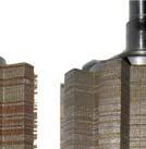

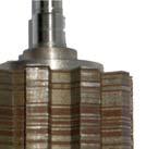
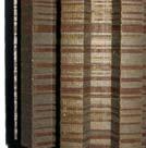

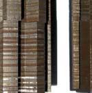

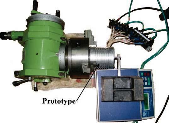
231 Chapter 6. Cogging Torque and Torque Ripple Minimizations of PMFS ISG with Different Rotor Configurations (a) (b) (c) Figure 6.15: Prototype and experimental setup: (a) stator; (b) three different rotors; (c) experimental setup. 197
232 6.6. Experimental Validation and Discussions smallest torque ripple, while the rotor teeth axial pairing and the 1.9 rotor pole arc width machines have similar torque ripples. It is also noted that that highest torque is delivered by the 1.9 rotor pole arc width machine. Cogging Torque (N.m) "1.9"3-D FEA "1.9"Measured "Step" 3-D FEA "Step"Measured "1.9&2.3" 3-D FEA "1.9&2.3"Measured Rotor Position (Degree) Figure 6.16: Cogging torque waveforms with different rotor configurations from 3-D FEA and experiment. 6.6 Experimental Validation and Discussions The stator and the three proposed rotor configurations are built for experimental validations of the FEA results. The prototypes and the experimental setup are shown in Figure The predicted cogging torque profiles of the machines from 3-D FEA are compared with the experimental results in Figure There are some noticeable deviations between the estimated and measured results, especially for the rotor step skewed and rotor teeth axial pairing machines. The phase back EMF waveforms from the 3-D FEA and experimental tests at 1000rpm are compared as in Figure 6.17, which shows the experimental ones are slightly smaller than the predicted. Moreover, the P-P cogging torque and dominant back EMF harmonics (1 st,5 th,7 th ) are given in Table 6.2 for further comparisons. The 198
233 Chapter 6. Cogging Torque and Torque Ripple Minimizations of PMFS ISG with Different Rotor Configurations Phase back EMF (V) "1.9" 3-D FEA "1.9"Measured "Step" 3-D FEA "Step"Measured "1.9&2.3" 3-D FEA "1.9&2.3"Measured Position (Degree) Figure 6.17: Phase back EMF waveforms with different rotor configurations from 3-D FEA and experiment. Table 6.2: P-P Cogging Torque and Back EMF Harmonics Comparisons Machine Parameters 2-D FEA 3-D FEA Experiment Uniform 1.9 P-P Cogging (N m) Uniform st EMF (V) Uniform th EMF (V) Uniform th EMF (V) Step Skewed P-P Cogging (N m) Step Skewed 1 st EMF (V) Step Skewed 5 th EMF (V) Step Skewed 7 th EMF (V) Teeth Axial Pairing P-P Cogging (N m) Teeth Axial Pairing 1 st EMF (V) Teeth Axial Pairing 5 th EMF (V) Teeth Axial Pairing 7 th EMF (V) FEA models are based on idealized machines with no mechanical tolerances and assembly deficiencies. In practice, it will be too costly, if not impossible, to build such an ideal machine. Allowing also for the errors due to experiment and soft- 199
234 6.6. Experimental Validation and Discussions ware limitations, it is felt that these results from the FEA models and experimental tests are in reasonable agreements. In addition, they also confirm that both the rotor step skewed and rotor teeth axial pairing techniques can effectively reduce the cogging torque, albeit at the expense of small attenuations on the back EMF. For the torque output and torque ripple tests, since the period of the torque pulsation is 6 (mechanical) due to machine symmetry as shown in Figure 6.14, it suffices to take 12 static torque measurements over a period of 6 (mechanical) by exciting the three phase winding with DC currents according to the rotor positions. The average torque and P-P torque ripple of the three proposed rotor configurations with different phase angles and rated current (50A) excitation from experiments are compared with the 3-D FEA results in Figure 6.18 and Figure 6.19 respectively. There are relatively larger discrepancies between the predicted and measured results, compared with the previous comparison on cogging torque and back EMF. In addition to the previous explanations, there are further measurement uncertainties in the DC currents in the machine windings, and more importantly the machines have 10 rotor poles which would amplify any rotor position errors by 10 times when conducting the measurements. These factors potentially attribute to more significant experimental errors, as evident in the comparisons shown in Figure 6.18 and Figure Nonetheless, the experimental results further confirm the superiority of the rotor step skewed for its smallest torque pulsations among the three machines, whilst the P-P torque ripples in the 1.9 rotor pole arc width and rotor teeth axial pairing machines are quite close with phase angles from -30 to 30. The average torque output of the machines with different current excitations and 0 phase angle from both 3-D FEA and experimental tests are illustrated in Figure 6.20, which show good agreements are achieved between the estimated and measured results, where the latter are only very slightly smaller than the former. Moreover, the corresponding torque profiles with rated current excitation and 0 phase angle from 3-D FEA and experimental tests are compared in Figure 6.21, and satisfactory agreements are again achieved. From the above comprehensive analysis and comparisons, the rotor step skewed technique not only can significantly reduce the cogging torque but also can greatly suppress the general torque ripple. Although the rotor teeth axial pairing technique can effectively mitigate the cogging torque, it is not particularly effective to suppress the overall torque pulsation. However, it should be noted 200
235 Chapter 6. Cogging Torque and Torque Ripple Minimizations of PMFS ISG with Different Rotor Configurations 5.4 Torque Output (N.m) "1.9" 3-D FEA "1.9" measured "step" 3-D FEA "step" measured "1.9&2.3" 3-D FEA "1.9&2.3" measured Phase Angle (Degree) Figure 6.18: Torque and phase advance angle characteristics with different rotor configurations from 3-D FEA and experiment. Torque Ripple (N.m) "1.9" 3-D FEA "1.9" measured "step" 3-D FEA "step" measured "1.9&2.3" 3-D FEA "1.9&2.3" measured Phase Angle (Degree) Figure 6.19: P-P torque ripple and phase advance angle characteristics with different rotor configurations from 3-D FEA and experiment. 201
236 6.6. Experimental Validation and Discussions Torque Output (N.m) "1.9" 3-D FEA "1.9" measured "Step" 3-D FEA "Step" measured "1.9&2.3" 3-D FEA "1.9&2.3" measured Q-axis Current (A) Figure 6.20: Torque and current characteristics with different rotor configurations from 3-D FEA and experiment "1.9" 3-D FEA "1.9" measured "step" 3-D FEA "step" measured "1.9&2.3" 3-D FEA "1.9&2.3" measured Torque (N.m) Rotor Postion (Degree) Figure 6.21: Torque profiles with different rotor configurations from 3-D FEA and experiment. 202
237 Chapter 6. Cogging Torque and Torque Ripple Minimizations of PMFS ISG with Different Rotor Configurations that both rotor step skewed and rotor teeth axial pairing techniques compromise the torque output of the machine. It is therefore important to critically appraise the feasibility of the technique to be deployed against the specific requirements of the application. 6.7 Summary Three rotor configurations have been proposed for cogging torque and torque ripple reduction of the PMFS ISG in this chapter. The uniform rotor configuration is used as a design benchmark for the other rotor step skewed and rotor teeth axial pairing configurations. Comprehensive FEA models have been developed for the machine s performance prediction. Experimental results have been carried out for the machine with three rotor configurations to validate the FEA models. The results show that the rotor step skewed and rotor teeth axial pairing techniques are both very effective in the reduction of the cogging torque for the proposed PMFS ISG. However, the rotor teeth axial pairing method can only accomplish torque ripple improvement with low load conditions and will even increase torque pulsations with high load conditions while the rotor step skewed method can effectively suppress torque ripple with full-range loads. Careful selection of the appropriate method is crucial for both cogging torque and torque ripple suppressions during the machine design stage. 203
238 6.7. Summary 204
239 Chapter 7 Conclusions and Future Work Three types of PMSM with FSCW configuration, AFPM SAT in-wheel machine, high speed coreless AFPM generator and outer-rotor PMFS machine for electric vehicle propulsion,are covered in this study. Furthermore, the novel axial pole pairing technique has been proposed to reduce the torque ripples especially the cogging torque in RFPM synchronous machine with FSCW configuration such as outer rotor surface mounted PMSM and PMFS machine. The corresponding conclusions and possible further works are presented hereafter. 7.1 Conclusions The following conclusions can be drawn based on the works accomplished in this study: AFPM SAT machine with laminated stator for in-wheel direct drive application Considerable deviation between the approximate analytical and 3-D FEA models exists due to the complex machine geometry. However, efficient analytical approach is of particular interest for quick determination of a feasible range initial design parameters. With these parameters as starting point, 3-D FEA can be used to determine the final optimal design and evaluate the corresponding performance. The anisotropic modeling of stator material in the 3-D FEA model should be applied in order to deliver a more realistic prediction of the electromagnetic behavior inside machine and hence more accurate estimations. Adopting the anisotropic model, the deviation between the predicted and measured back EMF can be improved by approximately 5%. The stator yoke in the proposed AFPM SAT machine could be eliminated completely so that the weight of the machine as well as the stator 205
240 7.1. Conclusions core losses could be significantly reduced. Consequently improved machine performance can be achieved by implementing such topology which has been verified by both 3-D FEA predictions and experimental tests on the prototype machine. In addition, the feature of laminated stator core configuration would also result in low material and manufacture costs. However the eddy current losses in stator pole holders, which are made of aluminium alloy, should be carefully considered. The eddy current losses in the magnets of the proposed AFPM SAT machine can be effectively mitigated by either radial or circumferential segmentations. The comprehensive 3-D FEA investigations have revealed that the impacts of radial and circumferential segmentations on magnet eddy current losses are almost equivalent. The magnet shaping scheme proposed in this study can be employed to effectively alleviate the cogging torque and overall torque pulsations of the proposed AFPM SAT machine. This technique would not deteriorate the machine performance or increase the manufacture cost. Coreless AFPM machine with circular magnets and coils for man-portable power platform The performance of the proposed coreless AFPM generator is strongly influenced by certain geometric parameters. An efficient yet accurate analytical model is employed in this study for the initial sizing and winding coil optimization of the machine. This model is validated by comprehensive 3-D FEA. High strength holders are essential to retain the magnets against high centrifugal force exerted as a result of high rotational speed to ensure the rotor integrity. 3-D structural FEA is comprehensively deployed in this study to predict the mechanical stresses in the rotor holders with different materials and radius. An optimal design of the magnet holder is finally decided and assured based on the mechanical analysis. Apart from the dominant stator resistive losses, the eddy current losses in the aluminium alloy magnet holders and rotor windage losses are substantial. The evaluations of these losses in the prototype machine are carried out in this study. The eddy current losses in the magnet 206
241 Chapter 7. Conclusions and Future Work holders under DC load are much more significant than the ones under AC load due to the considerable high time harmonics in the stator phase current. The circular magnets and winding coils in the proposed coreless AFPM generator would make the back EMF essentially sinusoidal. The enlarged air gap would accordingly reduce the armature reaction and synchronous reactance consequently resulting in improved power factor at high speed operation. Both the predicted and experimental results have validated that the proposed prototype is a compact and efficient high speed generator with very simple and robust structure. Additionally, this structure offers simplified assembly and manufacturing processes utilizing off-the-shelf magnets. Outer rotor PMFS machine for electric vehicle propulsion Severe saturation unavoidably occurs in the proposed original outer rotor PMFS machine due to the collective effects of excessive magnets and inadequate stator lamination material. Consequently, the machine suffers relatively low efficiency compared with other types of PMSM. An improved design has been carried out to significantly enhance the machine performance and effectively minimize the magnet volumes in this study. The eddy current losses induced in the magnets in the proposed PMFS machine are quite appreciable, hence the impact of radial segmentation of the magnet on magnet eddy current losses are investigated in detail in this study. The study has shown that the magnet eddy current losses can be effectively reduced by more than 70% when the magnets are evenly segmented into two pieces. Torque ripple suppression in direct drive FSCW surface mounted PMSM by axial pole pairing The magnet pole arc width has direct impact on the cogging torque, harmonic content of the back EMF and hence the overall torque pulsations of the proposed FSCW surface mounted PMSM. It is proven in this study that, in the proposed machine, the optimal magnet pole 207
242 7.1. Conclusions arc width ratio is about 0.72 for minimum cogging torque and 0.75 for minimum torque ripple under rated load condition by analytical and 2-D FEA models. The new axial pole pairing technique based on the magnet pole arc width results could reduce cogging torque and torque ripple effectively with different magnet pairs, which is validated by analytical, 2-D and 3-D FEA and experimental approaches. Moreover, careful selection is of particular importance for compromise between cogging torque and torque ripple minimizations during the machine design stage. The main merits of the proposed technique over its radial counterpart is that the symmetry of the machine is maintained and hence parallel connection of the coils in each phase is allowed. More importantly no unbalanced radial magnetic forces would be generated. Cogging torque and torque ripple minimizations of PMFS ISG with different rotor configurations The rotor pole arc width has direct impacts on the cogging torque and overall torque pulsations of the proposed PMFS ISG. The estimated results from 2-D FEA in this study have revealed that the optimal rotor pole arc width is about 1.9 or 2.3 times original one for minimum cogging torque and 1.9 times the original pole arc width for minimum torque ripple under rated load condition. It also has been shown that the machine with 1.7 rotor pole arc width can deliver the maximum torque. Both the FEA and experimental results have exhibited that the rotor step skewed and teeth axial pairing techniques can minimize the cogging torque of the proposed machine effectively. However the rotor teeth axial pairing method can only accomplish torque ripple improvement with low load conditions and would even increase torque pulsations with high load conditions while the rotor step skewed design can suppress torque ripple effectively with full-range loads, compared with the uniform rotor pole arc width of
243 Chapter 7. Conclusions and Future Work 7.2 Proposed Future Works Several recommendations on possible future work are listed as follows: AFPM SAT machine with laminated stator for in-wheel direct drive application Although the losses and efficiency map of the proposed AFPM SAT machine are comprehensively estimated, the thermal behavior of the machine could be of extreme importance. Thermal network model could be established to predict the thermal behavior and identify the crucial parts of the thermal design of the machine. Additionally, thermocouples could be positioned at different parts of the prototype to simultaneously monitor the temperature distributions during the machine test. Maximum overload capability of the prototype could be carried out within the thermal limitations in different parts of the machine. The prototype machine with the proposed optimal magnet shape could be fabricated, and various experimental tests can be conducted to further verify the proposed cogging torque and torque ripple reduction technique. Since the prototype machine built in this study is not fully optimized, optimal design approaches incorporated with the proposed analytical model and thermal network model could be developed to optimize the machine parameters such as stator and rotor pole number combinations and winding axial length, hence further improve the machine performance. Moreover, modern and elaborate manufacturing techniques could be surveyed and exploited to improve the rigidness and robustness of the machine. Coreless AFPM machine with circular magnets and coils for man-portable power platform The copper resistive losses in the stator winding are the major contributors to the overall machine losses, and further the coils are potted 209
244 7.2. Proposed Future Works in epoxy resins which cannot withstand high temperature. Consequently, a rather simple thermal network model could be developed to efficiently evaluate the maximum stator current allowed based on the thermal limitations of the material for different configurations. Comprehensive optimizations of substantive machine parameters, such as multi-objective particle swarm and evolutional optimizations, including thermal and mechanical limitations would be implemented to further improve the machine performance. Mechanical losses of the proposed machine at such high operational speed could be fairly considerable, more insightful and detailed study of the mechanical losses in the proposed machine could be carried out together with complex thermal predictions. Outer rotor PMFS machine for electric vehicle propulsion The established study has shown the performance of the proposed outer rotor PMFS machine is promising based on the 2-D FEA evaluations. Prototype machines would be manufactured and tested to further confirm the proposed machine as a compelling contender for electric vehicle propulsion. Parametric 2-D FEA program involving the main geometric parameters of the proposed machine could be developed. Optimizations with different objective and cost functions could be further investigated. For instance, the cogging torque and torque ripple could be optimized, since the proposed prototype exhibits remarkable cogging torque and hence overall torque ripple. The magnets would induce significant slot leakages inside the slot due to the large slot opening, which could be observed in the flux distribution figures. Further the windings near the slot opening are directly exposed to the PM slot leakage and therefore considerable eddy current losses could be generated. The eddy current losses in the stator windings caused by the PM slot leakages, as well as winding proximity losses, could be comprehensively studied in order to predict the machine performance more accurately. 210
245 Chapter 7. Conclusions and Future Work The proposed axial pairing technique have been implemented in outer rotor surface mounted PMSM and PMFS ISG to mitigate the cogging torque and torque ripple in this study. However, the effects of the proposed method on different types of radial flux PMSM such as interior PMSM, PM flux reversal machine, could be examined in more detail. 211
246 7.2. Proposed Future Works 212
247 References
248
249 References Adamson, G. & Ortiz, L. (2007). High energy battery materials. WIPO Patent Application WO/2007/ Akita, H., Nakahara, Y., Miyake, N., & Oikawa, T. (2003). New core structure and manufacturing method for high efficiency of permanent magnet motors. In Industry Applications Conference, th IAS Annual Meeting. Conference Record of the, volume 1, (pp vol.1). Alberti, L., Barcaro, M., Pre, M., Faggion, A., Sgarbossa, L., Bianchi, N., & Bolognani, S. (2010). Ipm machine drive design and tests for an integrated starteralternator application. Industry Applications, IEEE Transactions on, 46(3), Amara, Y., Hoang, E., Gabsi, M., & Lecriv, M. (2005). Design and comparison of different flux-switching synchronous machines for an aircraft oil breather application. Euro. Trans. Electr. Power, 15, Amara, Y., Reghem, P., & Barakat, G. (2010). Analytical prediction of eddycurrent loss in armature windings of permanent magnet brushless ac machines. Magnetics, IEEE Transactions on, 46(8), Anpalahan, P. & Lamperth, M. (2006). Design of multi-stack axial flux permanent magnet generator for a hybrid electric vehicle. In Vehicle Power and Propulsion Conference, VPPC 06. IEEE, (pp. 1 4). Atallah, K., Howe, D., Mellor, P., & Stone, D. (2000). Rotor loss in permanentmagnet brushless ac machines. Industry Applications, IEEE Transactions on, 36(6), Atallah, K., Wang, J., & Howe, D. (2003). Torque-ripple minimization in modular permanent-magnet brushless machines. Industry Applications, IEEE Transactions on, 39(6), Atkinson, G., Mecrow, B., Jack, A., Atkinson, D., Sangha, P., & Benarous, M. (2006). The analysis of losses in high-power fault-tolerant machines for aerospace applications. Industry Applications, IEEE Transactions on, 42(5),
250 References Aydin, M., Huang, S., & Lipo, T. (2001). Optimum design and 3d finite element analysis of nonslotted and slotted internal rotor type axial flux pm disc machines. In Power Engineering Society Summer Meeting, IEEE, volume 3, (pp vol.3). Aydin, M., Huang, S., & Lipo, T. (2006). Torque quality and comparison of internal and external rotor axial flux surface-magnet disc machines. Industrial Electronics, IEEE Transactions on, 53(3), Aydin, M., Zhu, Z., Lipo, T., & Howe, D. (2007). Minimization of cogging torque in axial-flux permanent-magnet machines: Design concepts. Magnetics, IEEE Transactions on, 43(9), Azar, Z., Wu, L., Evans, D., & Zhu, Z. (2010). Influence of rotor configuration on iron and magnet losses of fractional-slot ipm machines. In Power Electronics, Machines and Drives (PEMD 2010), 5th IET International Conference on, (pp. 1 6). Azzouzi, J., Barakat, G., & Dakyo, B. (2005). Quasi-3-d analytical modeling of the magnetic field of an axial flux permanent-magnet synchronous machine. Energy Conversion, IEEE Transactions on, 20(4), Barcaro, M., Bianchi, N., & Magnussen, F. (2009). Configurations of fractional-slot ipm motors with dual three-phase winding. (pp ). Beerten, J., Verveckken, J., & Driesen, J. (2010). Predictive direct torque control for flux and torque ripple reduction. Industrial Electronics, IEEE Transactions on, 57(1), Bianchi, N. & Bolognani, S. (2002). Design techniques for reducing the cogging torque in surface-mounted pm motors. Industry Applications, IEEE Transactions on, 38(5), Bianchi, N., Bolognani, S., & Pre, M. (2007). Strategies for the fault-tolerant current control of a five-phase permanent-magnet motor. Industry Applications, IEEE Transactions on, 43(4), Bianchi, N., Bolognani, S., & Pre, M. (2008). Impact of stator winding of a fivephase permanent-magnet motor on postfault operations. Industrial Electronics, IEEE Transactions on, 55(5),
251 References Bianchi, N., Bolognani, S., Pre, M., & Grezzani, G. (2006). Design considerations for fractional-slot winding configurations of synchronous machines. Industry Applications, IEEE Transactions on, 42(4), Bianchi, N. & Dai Pre, M. (2006). Use of the star of slots in designing fractional-slot single-layer synchronous motors. Electric Power Applications, IEE Proceedings -, 153(3), Bianchi, N. & Fornasiero, E. (2009a). Impact of mmf space harmonic on rotor losses in fractional-slot permanent-magnet machines. Energy Conversion, IEEE Transactions on, 24(2), Bianchi, N. & Fornasiero, E. (2009b). Index of rotor losses in three-phase fractionalslot permanent magnet machines. Electric Power Applications, IET, 3(5), Boldea, I., Zhang, J., & Nasar, S. (2002). Theoretical characterization of flux reversal machine in low-speed servo drives-the pole-pm configuration. Industry Applications, IEEE Transactions on, 38(6), Boughrara, K., Ibtiouen, R., Zarko, D., Touhami, O., & Rezzoug, A. (2010). Magnetic field analysis of external rotor permanent-magnet synchronous motors using conformal mapping. Magnetics, IEEE Transactions on, 46(9), Bumby, J. & Martin, R. (2005). Axial-flux permanent-magnet air-cored generator for small-scale wind turbines. Electric Power Applications, IEE Proceedings -, 152(5), Caricchi, F., Crescimbini, F., Di Napoli, A., & Marcheggiani, M. (1996). Prototype of electric vehicle drive with twin water-cooled wheel direct drive motors. In Power Electronics Specialists Conference, PESC 96 Record., 27th Annual IEEE, volume 2, (pp vol.2). Caricchi, F., Crescimbini, F., Fedeli, E., & Noioa, G. (1994). Design and construction of a wheel-directly-coupled axial-flux pm motor prototype for evs. In Industry Applications Society Annual Meeting, 1994., Conference Record of the 1994 IEEE, (pp vol.1). Caricchi, F., Crescimbini, F., & Honorati, O. (1998). Low-cost compact permanent magnet machine for adjustable-speed pump application. Industry Applications, IEEE Transactions on, 34(1),
252 References Caricchi, F., Crescimbini, F., & Honrati, O. (1999). Modular axial-flux permanentmagnet motor for ship propulsion drives. Energy Conversion, IEEE Transactions on, 14(3), Caricchi, F., Crescimbini, F., Mezzetti, F., & Santini, E. (1996). Multistage axial-flux pm machine for wheel direct drive. Industry Applications, IEEE Transactions on, 32(4), Caricchi, F., Crescimbini, F., & Santini, E. (1995). Basic principle and design criteria of axial-flux pm machines having counterrotating rotors. Industry Applications, IEEE Transactions on, 31(5), Carter, G. W. (1967). The Electromagnetic Field in Its Engineering Aspect (2 ed.). Longman. Cavagnino, A., Lazzari, M., Profumo, F., & Tenconi, A. (2000). Axial flux interior pm synchronous motor: parameters identification and steady-state performance measurements. Industry Applications, IEEE Transactions on, 36(6), Chan, T. & Lai, L. (2007). An axial-flux permanent-magnet synchronous generator for a direct-coupled wind-turbine system. Energy Conversion, IEEE Transactions on, 22(1), Chen, A., Rotevatn, N., Nilssen, R., & Nysveen, A. (2009). Characteristic investigations of a new three-phase flux-switching permanent magnet machine by fem simulations and experimental verification. In Electrical Machines and Systems, ICEMS International Conference on, (pp. 1 6). Chen, J. & Zhu, Z. (2010a). Comparison of all- and alternate-poles-wound fluxswitching pm machines having different stator and rotor pole numbers. Industry Applications, IEEE Transactions on, 46(4), Chen, J. & Zhu, Z. (2010b). Influence of the rotor pole number on optimal parameters in flux-switching pm brushless ac machines by the lumped-parameter magnetic circuit model. Industry Applications, IEEE Transactions on, 46(4),
253 References Chen, J. & Zhu, Z. (2010c). Winding configurations and optimal stator and rotor pole combination of flux-switching pm brushless ac machines. Energy Conversion, IEEE Transactions on, 25(2), Chen, J., Zhu, Z., & Howe, D. (2008a). Stator and rotor pole combinations for multitooth flux-switching permanent-magnet brushless ac machines. Magnetics, IEEE Transactions on, 44(12), Chen, S., Namuduri, C., & Mir, S. (2002). Controller-induced parasitic torque ripples in a pm synchronous motor. Industry Applications, IEEE Transactions on, 38(5), Chen, Y., Chen, S., Zhu, Z., Howe, D., & Ye, Y. (2006). Starting torque of singlephase flux-switching permanent magnet motors. Magnetics, IEEE Transactions on, 42(10), Chen, Y., Zhu, Z., & Howe, D. (2006). Vibration of pm brushless machines having a fractional number of slots per pole. Magnetics, IEEE Transactions on, 42(10), Chen, Y., Zhu, Z., & Howe, D. (2008b). Three-dimensional lumped-parameter magnetic circuit analysis of single-phase flux-switching permanent-magnet motor. Industry Applications, IEEE Transactions on, 44(6), Cheng, M., Chau, K., & Chan, C. (2001a). Design and analysis of a new doubly salient permanent magnet motor. Magnetics, IEEE Transactions on, 37(4), Cheng, M., Chau, K., & Chan, C. (2001b). Static characteristics of a new doubly salient permanent magnet motor. Energy Conversion, IEEE Transactions on, 16(1), Cheng, M., Chau, K., Chan, C., Zhou, E., & Huang, X. (2000). Nonlinear varyingnetwork magnetic circuit analysis for doubly salient permanent-magnet motors. Magnetics, IEEE Transactions on, 36(1), Cheng, S. P. & Hwang, C. C. (2007). Design of high-performance spindle motors with single-layer concentrated windings and unequal tooth widths. Magnetics, IEEE Transactions on, 43(2),
254 References Cheng, Y., Pollock, C., & Pollock, H. (2005). A permanent magnet flux switching motor for low energy axial fans. In Industry Applications Conference, Fourtieth IAS Annual Meeting. Conference Record of the 2005, volume 3, (pp Vol. 3). Chong, L., Dutta, R., & Rahman, M. (2008a). Parameter analysis of an ipm machine with fractional-slot concentrated windings, part i: Open-circuit analysis. In Power Engineering Conference, AUPEC 08. Australasian Universities, (pp. 1 5). Chong, L., Dutta, R., & Rahman, M. (2008b). Parameter analysis of an ipm machine with fractional-slot concentrated windings, part ii: Including armaturereaction. In Power Engineering Conference, AUPEC 08. Australasian Universities, (pp. 1 6). Chong, L. & Rahman, M. (2010). Saliency ratio derivation and optimisation for an interior permanent magnet machine with concentrated windings using finiteelement analysis. Electric Power Applications, IET, 4(4), Cros, J. & Viarouge, P. (2002). Synthesis of high performance pm motors with concentrated windings. Energy Conversion, IEEE Transactions on, 17(2), Cros, J. & Viarouge, P. (2004). New structures of polyphase claw-pole machines. Industry Applications, IEEE Transactions on, 40(1), Cros, J., Viarouge, P., Chalifour, Y., & Figueroa, J. (2004). A new structure of universal motor using soft magnetic composites. Industry Applications, IEEE Transactions on, 40(2), Cros, J., Viarouge, P., & Gelinas, C. (1998). Design of pm brushless motors using iron-resin composites for automotive applications. In Industry Applications Conference, Thirty-Third IAS Annual Meeting. The 1998 IEEE, volume 1, (pp vol.1). Curiac, P. & Kang, D. H. (2007). Preliminary evaluation of a megawatt-class lowspeed axial flux pmsm with self-magnetization function of the armature coils. Energy Conversion, IEEE Transactions on, 22(3),
255 References Deodhar, R., Andersson, S., Boldea, I., & Miller, T. (1997). The flux-reversal machine: a new brushless doubly-salient permanent-magnet machine. Industry Applications, IEEE Transactions on, 33(4), Dorrell, D. G., Popescu, M., & Ionel, D. M. (2010). Unbalanced magnetic pull due to asymmetry and low-level static rotor eccentricity in fractional-slot brushless permanent-magnet motors with surface-magnet and consequent-pole rotors. Magnetics, IEEE Transactions on, 46(7), Dubas, F. & Espanet, C. (2009). Analytical solution of the magnetic field in permanent-magnet motors taking into account slotting effect: No-load vector potential and flux density calculation. Magnetics, IEEE Transactions on, 45(5), Dwari, S. & Parsa, L. (2008). An optimal control technique for multiphase pm machines under open-circuit faults. Industrial Electronics, IEEE Transactions on, 55(5), Eastham, J., Profumo, F., Tenconi, A., Hill-Cottingham, R., Coles, P., & Gianolio, G. (2002). Novel axial flux machine for aircraft drive: design and modeling. Magnetics, IEEE Transactions on, 38(5), Ede, J., Atallah, K., Jewell, G., Wang, J., & Howe, D. (2007). Effect of axial segmentation of permanent magnets on rotor loss in modular permanent-magnet brushless machines. Industry Applications, IEEE Transactions on, 43(5), El-Hasan, T. & Luk, P. (2003). Magnet topology optimization to reduce harmonics in high-speed axial flux generators. Magnetics, IEEE Transactions on, 39(5), El-Hasan, T., Luk, P., Bhinder, F., & Ebaid, M. (2000). Modular design of highspeed permanent-magnet axial-flux generators. Magnetics, IEEE Transactions on, 36(5), EL-Refaie, A. (2010). Fractional-slot concentrated-windings synchronous permanent magnet machines: Opportunities and challenges. Industrial Electronics, IEEE Transactions on, 57(1),
256 References EL-Refaie, A. & Jahns, T. (2005). Optimal flux weakening in surface pm machines using fractional-slot concentrated windings. Industry Applications, IEEE Transactions on, 41(3), El-Refaie, A. & Jahns, T. (2006). Scalability of surface pm machines with concentrated windings designed to achieve wide speed ranges of constant-power operation. Energy Conversion, IEEE Transactions on, 21(2), El-Refaie, A. & Jahns, T. (2008). Impact of winding layer number and magnet type on synchronous surface pm machines designed for wide constant-power speed range operation. Energy Conversion, IEEE Transactions on, 23(1), El-Refaie, A., Jahns, T., McCleer, P., & McKeever, J. (2006). Experimental verification of optimal flux weakening in surface pm machines using concentrated windings. Industry Applications, IEEE Transactions on, 42(2), El-Refaie, A., Jahns, T., & Novotny, D. (2006). Analysis of surface permanent magnet machines with fractional-slot concentrated windings. Energy Conversion, IEEE Transactions on, 21(1), El-Refaie, A., Shah, M., Qu, R., & Kern, J. (2008). Effect of number of phases on losses in conducting sleeves of surface pm machine rotors equipped with fractional-slot concentrated windings. Industry Applications, IEEE Transactions on, 44(5), Fang, L., Kim, S.-I., Kwon, S.-O., & Hong, J.-P. (2010). Novel double-barrier rotor designs in interior-pm motor for reducing torque pulsation. Magnetics, IEEE Transactions on, 46(6), Fang, Z., Wang, Y., Shen, J., & Huang, Z. (2008). Design and analysis of a novel fluxswitching permanent magnet integrated-starter-generator. In Power Electronics, Machines and Drives, PEMD th IET Conference on, (pp ). Fei, W. & Luk, P. (2008a). Cogging torque reduction techniques for axial-flux surface-mounted permanent-magnet segmented-armature-torus machines. In Industrial Electronics, ISIE IEEE International Symposium on, (pp ). 222
257 References Fei, W. & Luk, P. (2008b). Design of a 1kw high speed axial flux permanent-magnet machine. In Power Electronics, Machines and Drives, PEMD th IET Conference on, (pp ). Fei, W. & Luk, P. (2009a). Design and performance analysis of a high-speed aircored axial-flux permanent-magnet generator with circular magnets and coils. In Electric Machines and Drives Conference, IEMDC 09. IEEE International, (pp ). Fei, W. & Luk, P. (2009b). An improved model for the back-emf and cogging torque characteristics of a novel axial flux permanent magnet synchronous machine with a segmental laminated stator. Magnetics, IEEE Transactions on, 45(10), Fei, W. & Luk, P. (2009c). Performance study of two axial-flux permanent-magnet machine topologies with soft magnetic composite cores. In Power Electronics and Motion Control Conference, IPEMC 09. IEEE 6th International, (pp ). Fei, W. & Luk, P. (2009d). Torque ripple reduction of axial flux permanent magnet synchronous machine with segmented and laminated stator. In Energy Conversion Congress and Exposition, ECCE IEEE, (pp ). Fei, W. & Luk, P. (2010). A new technique of cogging torque suppression in direct-drive permanent-magnet brushless machines. Industry Applications, IEEE Transactions on, 46(4), Fei, W., Luk, P., & Jinupun, K. (2008). A new axial flux permanent magnet segmented-armature-torus machine for in-wheel direct drive applications. In Power Electronics Specialists Conference, PESC IEEE, (pp ). Fei, W., Luk, P., Shen, J., & Wang, Y. (2009). A novel outer-rotor permanentmagnet flux-switching machine for urban electric vehicle propulsion. In Power Electronics Systems and Applications, PESA rd International Conference on, (pp. 1 6). Fei, W., Luk, P., Xia, B., Wang, Y., & Shen, J. X. (2010). Permanent mag flux switching integrated-startor-generator with different rotor configurations for 223
258 References cogging torque and torque ripple mitigations. In Energy Conversion Congress and Exposition, ECCE IEEE, (pp ). Fei, W. & Shen, J. (2006a). Comparative study and optimal design of pm switching flux motors. In Universities Power Engineering Conference, UPEC 06. Proceedings of the 41st International, volume 2, (pp ). Fei, W. & Shen, J. (2006b). Novel permanent magnet switching flux motors. In Universities Power Engineering Conference, UPEC 06. Proceedings of the 41st International, volume 2, (pp ). Ferreira, A., Silva, A., & Costa, A. (2007). Prototype of an axial flux permanent magnet generator for wind energy systems applications. In Power Electronics and Applications, 2007 European Conference on, (pp. 1 9). Ficheux, R., Caricchi, F., Crescimbini, F., & Honorati, O. (2001). Axial-flux permanent-magnet motor for direct-drive elevator systems without machine room. Industry Applications, IEEE Transactions on, 37(6), Germishuizen, J. & Kamper, M. (2009). Ipm traction machine with single layer nonoverlapping concentrated windings. Industry Applications, IEEE Transactions on, 45(4), Gieras, J. (2004). Analytical approach to cogging torque calculation of pm brushless motors. Industry Applications, IEEE Transactions on, 40(5), Gieras, J. F., Wang, R. J., & Kamper, M. J. (2008). Axial FLux Permanent Magnet Brushless Machines (2 ed.). Springer. Gong, Y., Chau, K., Jiang, J., Yu, C., & Li, W. (2009). Design of doubly salient permanent magnet motors with minimum torque ripple. Magnetics, IEEE Transactions on, 45(10), Gonzalez, D., Tapia, J., & Bettancourt, A. (2007). Design consideration to reduce cogging torque in axial flux permanent-magnet machines. Magnetics, IEEE Transactions on, 43(8), Guo, Y., Zhu, J. G., Watterson, P., & Wu, W. (2006). Development of a pm transverse flux motor with soft magnetic composite core. Energy Conversion, IEEE Transactions on, 21(2),
259 References Gysen, B., Ilhan, E., Meessen, K., Paulides, J., & Lomonova, E. (2010). Modeling of flux switching permanent magnet machines with fourier analysis. Magnetics, IEEE Transactions on, 46(6), Han, S.-H., Jahns, T., Soong, W., Guven, M., & Illindala, M. (2010). Torque ripple reduction in interior permanent magnet synchronous machines using stators with odd number of slots per pole pair. Energy Conversion, IEEE Transactions on, 25(1), Haylock, J., Mecrow, B., Jack, A., & Atkinson, D. (1998). Operation of a fault tolerant pm drive for an aerospace fuel pump application. Electric Power Applications, IEE Proceedings -, 145(5), Hill-Cottingham, R., Coles, P., Eastham, J., Profumo, F., Tenconi, A., & Gianolio, G. (2001). Multi-disc axial flux stratospheric aircraft propeller drive. In Industry Applications Conference, Thirty-Sixth IAS Annual Meeting. Conference Record of the 2001 IEEE, volume 3, (pp vol.3). Hill-Cottingham, R., Coles, P., Eastham, J., Profumo, F., Tenconi, A., Gianolio, G., & Cerchio, M. (2002). Plastic structure multi-disc axial flux pm motor. In Industry Applications Conference, th IAS Annual Meeting. Conference Record of the, volume 2, (pp vol.2). Hoang, E., Ben-Ahmed, A. H., & Lucidarme, J. (1997). Switching flux permanent magnet polyphased synchronous machines. In Power Electronics and Applications, EPE 97. 7th European Conference on, (pp ). Hoang, E., Gabsi, M., Lecrivain, M., & Multon, B. (2000). Influence of magnetic losses on maximum power limits of synchronous permanent magnet drives in flux-weakening mode. In Industry Applications Conference, Conference Record of the 2000 IEEE, volume 1, (pp vol.1). Hoang, E., Hlioui, S., Lecrivain, M., & Gabsi, M. (2009). Experimental comparison of lamination material case of switching flux synchronous machine with hybrid excitation. In Power Electronics and Applications, EPE th European Conference on, (pp. 1 7). 225
260 References Hosseini, S., Agha-Mirsalim, M., & Mirzaei, M. (2008). Design, prototyping, and analysis of a low cost axial-flux coreless permanent-magnet generator. Magnetics, IEEE Transactions on, 44(1), Hua, W. & Cheng, M. (2008). Cogging torque reduction of flux-switching permanent magnet machines without skewing. In Electrical Machines and Systems, ICEMS International Conference on, (pp ). Hua, W., Cheng, M., & Zhang, G. (2009). A novel hybrid excitation flux-switching motor for hybrid vehicles. Magnetics, IEEE Transactions on, 45(10), Hua, W., Cheng, M., Zhu, Z., & Howe, D. (2006). Design of flux-switching permanent magnet machine considering the limitation of inverter and fluxweakening capability. In Industry Applications Conference, st IAS Annual Meeting. Conference Record of the 2006 IEEE, volume 5, (pp ). Hua, W., Cheng, M., Zhu, Z., & Howe, D. (2008). Analysis and optimization of back emf waveform of a flux-switching permanent magnet motor. Energy Conversion, IEEE Transactions on, 23(3), Hua, W. & Ming, C. (2006). Inductance characteristics of 3-phase flux-switching permanent magnet machine with doubly-salient structure. In Power Electronics and Motion Control Conference, IPEMC CES/IEEE 5th International, volume 3, (pp. 1 5). Huang, S., Aydin, M., & Lipo, T. (2001). Torus concept machines: pre-prototyping design assessment for two major topologies. In Industry Applications Conference, Thirty-Sixth IAS Annual Meeting. Conference Record of the 2001 IEEE, volume 3, (pp vol.3). Huang, W.-Y., Bettayeb, A., Kaczmarek, R., & Vannier, J.-C. (2010). Optimization of magnet segmentation for reduction of eddy-current losses in permanent magnet synchronous machine. Energy Conversion, IEEE Transactions on, 25(2), Hwang, C., Cheng, S., & Chang, C. (2005). Design of high-performance spindle motors with concentrated windings. Magnetics, IEEE Transactions on, 41(2),
261 References Hwang, C.-C., Li, P.-L., Chuang, F., Liu, C.-T., & Huang, K.-H. (2009). Optimization for reduction of torque ripple in an axial flux permanent magnet machine. Magnetics, IEEE Transactions on, 45(3), Hwang, K., Jo, J., & Kwon, B. (2009). A study on optimal pole design of spoke-type ipmsm with concentrated winding for reducing the torque ripple by experiment design method. Magnetics, IEEE Transactions on, 45(10), Ilhan, E., Gysen, B., Paulides, J., & Lomonova, E. (2010). Analytical hybrid model for flux switching permanent magnet machines. Magnetics, IEEE Transactions on, 46(6), Ishak, D., Zhu, Z., & Howe, D. (2005a). Eddy-current loss in the rotor magnets of permanent-magnet brushless machines having a fractional number of slots per pole. Magnetics, IEEE Transactions on, 41(9), Ishak, D., Zhu, Z., & Howe, D. (2005b). Permanent-magnet brushless machines with unequal tooth widths and similar slot and pole numbers. Industry Applications, IEEE Transactions on, 41(2), Ishak, D., Zhu, Z., & Howe, D. (2006). Comparison of pm brushless motors, having either all teeth or alternate teeth wound. Energy Conversion, IEEE Transactions on, 21(1), Islam, M., Mir, S., Sebastian, T., & Underwood, S. (2005). Design considerations of sinusoidally excited permanent-magnet machines for low-torque-ripple applications. Industry Applications, IEEE Transactions on, 41(4), Islam, R., Husain, I., Fardoun, A., & McLaughlin, K. (2009). Permanent-magnet synchronous motor magnet designs with skewing for torque ripple and cogging torque reduction. Industry Applications, IEEE Transactions on, 45(1), Iwasaki, S., Deodhar, R., Liu, Y., Pride, A., Zhu, Z., & Bremner, J. (2009). Influence of pwm on the proximity loss in permanent-magnet brushless ac machines. Industry Applications, IEEE Transactions on, 45(4), Jack, A., Mecrow, B., Dickinson, P., Stephenson, D., Burdess, J., Fawcett, N., & Evans, J. (2000). Permanent-magnet machines with powdered iron cores and prepressed windings. Industry Applications, IEEE Transactions on, 36(4),
262 References Jack, A., Mecrow, B., Nord, G., & Dickinso, P. (2005). Axial flux motors using compacted insulated iron powder and laminations - design and test results. In Electric Machines and Drives, 2005 IEEE International Conference on, (pp ). Jahns, T. & Soong, W. (1996). Pulsating torque minimization techniques for permanent magnet ac motor drives-a review. Industrial Electronics, IEEE Transactions on, 43(2), Javadi, S. & Mirsalim, M. (2008). A coreless axial-flux permanent-magnet generator for automotive applications. Magnetics, IEEE Transactions on, 44(12), Jia, H., Cheng, M., Hua, W., Zhao, W., & Li, W. (2010). Torque ripple suppression in flux-switching pm motor by harmonic current injection based on voltage space-vector modulation. Magnetics, IEEE Transactions on, 46(6), Jian, L., Chau, K., Gong, Y., Yu, C., & Li, W. (2009). Analytical calculation of magnetic field in surface-inset permanent magnet motors. Magnetics, IEEE Transactions on, 45(10), Jin, C.-S., Jung, D.-S., Kim, K.-C., Chun, Y.-D., Lee, H.-W., & Lee, J. (2009). A study on improvement magnetic torque characteristics of ipmsm for direct drive washing machine. Magnetics, IEEE Transactions on, 45(6), Jin, M., Wang, Y., Shen, J., Luk, P., Fei, W., & Wang, C. (2010). Cogging torque suppression in a permanentmagnet flux-switching integrated-startergenerator. Electric Power Applications, IET, 4(8), Jin, M.-J., Wang, C.-F., Shen, J.-X., & Xia, B. (2009). A modular permanent-magnet flux-switching linear machine with fault-tolerant capability. Magnetics, IEEE Transactions on, 45(8), Kamper, M., Wang, R.-J., & Rossouw, F. (2008). Analysis and performance of axial flux permanent-magnet machine with air-cored nonoverlapping concentrated stator windings. Industry Applications, IEEE Transactions on, 44(5), Kano, Y. & Matsui, N. (2008). A design approach for direct-drive permanentmagnet motors. Industry Applications, IEEE Transactions on, 44(2),
263 References Kano, Y., Watanabe, K., Kosaka, T., & Matsui, N. (2009). A novel approach for circuit-field-coupled time-stepping electromagnetic analysis of saturated interior pm motors. Industry Applications, IEEE Transactions on, 45(4), Khan, M., Dosiek, L., & Pillay, P. (2006). Design and analysis of a pm wind generator with a soft magnetic composite core. In Industrial Electronics, 2006 IEEE International Symposium on, volume 3, (pp ). Khan, M., Pillay, P., Batane, N., & Morrison, D. (2006). Prototyping a composite smc/steel axial-flux pm wind generator. In Industry Applications Conference, st IAS Annual Meeting. Conference Record of the 2006 IEEE, volume 5, (pp ). Khan, M., Pillay, P., Guan, R., Batane, N., & Morrison, D. (2007). Performance assessment of a pm wind generator with machined smc cores. In Electric Machines Drives Conference, IEMDC 07. IEEE International, volume 2, (pp ). Kim, U. & Lieu, D. (1998a). Magnetic field calculation in permanent magnet motors with rotor eccentricity: with slotting effect considered. Magnetics, IEEE Transactions on, 34(4), Kim, U. & Lieu, D. (1998b). Magnetic field calculation in permanent magnet motors with rotor eccentricity: without slotting effect. Magnetics, IEEE Transactions on, 34(4), Kumar, P. & Bauer, P. (2008). Improved analytical model of a permanent-magnet brushless dc motor. Magnetics, IEEE Transactions on, 44(10), Kurronen, P. & Pyrhonen, J. (2007). Analytic calculation of axial-flux permanentmagnet motor torque. Electric Power Applications, IET, 1(1), Lee, D.-C. & Lee, G.-M. (1998). A novel overmodulation technique for space-vector pwm inverters. Power Electronics, IEEE Transactions on, 13(6), Lee, G.-H., Kim, S.-I., Hong, J.-P., & Bahn, J.-H. (2008). Torque ripple reduction of interior permanent magnet synchronous motor using harmonic injected current. Magnetics, IEEE Transactions on, 44(6),
264 References Lee, S.-H., Hong, J.-P., Hwang, S.-M., Lee, W.-T., Lee, J.-Y., & Kim, Y.-K. (2009). Optimal design for noise reduction in interior permanent-magnet motor. Industry Applications, IEEE Transactions on, 45(6), Letelier, A., Gonzalez, D., Tapia, J., Wallace, R., & Valenzuela, M. (2007). Cogging torque reduction in an axial flux pm machine via stator slot displacement and skewing. Industry Applications, IEEE Transactions on, 43(3), Liao, Y., Liang, F., & Lipo, T. (1995). A novel permanent magnet motor with doubly salient structure. Industry Applications, IEEE Transactions on, 31(5), Liu, C.-T., Lin, S.-C., Zamora, J., & Chiang, T.-S. (2003). Optimal operational strategy design of a single-sided permanent magnet axial-flux motor for electrical vehicle application. In Industry Applications Conference, th IAS Annual Meeting. Conference Record of the, volume 3, (pp vol.3). Liu, Z. & Li, J. (2007). Analytical solution of air-gap field in permanent-magnet motors taking into account the effect of pole transition over slots. Magnetics, IEEE Transactions on, 43(10), Liu, Z. & Li, J. (2008). Accurate prediction of magnetic field and magnetic forces in permanent magnet motors using an analytical solution. Energy Conversion, IEEE Transactions on, 23(3), Lovatt, H., Ramsden, V., & Mecrow, B. (1998). Design of an in-wheel motor for a solar-powered electric vehicle. Electric Power Applications, IEE Proceedings -, 145(5), Lubin, T., Mezani, S., & Rezzoug, A. (2010). Exact analytical method for magnetic field computation in the air gap of cylindrical electrical machines considering slotting effects. Magnetics, IEEE Transactions on, 46(4), Luk, P. (2008). The balance of power. Defence Management Journal, 43(4), Magnussen, F. & Lendenmann, H. (2007). Parasitic effects in pm machines with concentrated windings. Industry Applications, IEEE Transactions on, 43(5),
265 References Marignetti, F., Tomassi, G., Cancelliere, P., Delli Colli, V., Di Stefano, R., & Scarano, M. (2006). Electromagnetic and mechanical design of a fractional-slot-windings axial-flux pm synchronous machine with soft magnetic compound stator. In Industry Applications Conference, st IAS Annual Meeting. Conference Record of the 2006 IEEE, volume 1, (pp ). Mattavelli, P., Tubiana, L., & Zigliotto, M. (2005). Torque-ripple reduction in pm synchronous motor drives using repetitive current control. Power Electronics, IEEE Transactions on, 20(6), Mecrow, B., Jack, A., Atkinson, D., Green, S., Atkinson, G., King, A., & Green, B. (2004). Design and testing of a four-phase fault-tolerant permanent-magnet machine for an engine fuel pump. Energy Conversion, IEEE Transactions on, 19(4), Mecrow, B., Jack, A., Haylock, J., & Coles, J. (1996). Fault-tolerant permanent magnet machine drives. Electric Power Applications, IEE Proceedings -, 143(6), Meier, F. (2008). Permanent-Magnet Synchronous Machines with Non-Overlapping Concentrated Windings for Low-Speed Direct-Drive Applications. PhD thesis, Royal Institute of Technology (KTH). Mitcham, A., Antonopoulos, G., & Cullen, J. (2004). Favourable slot and pole number combinations for fault-tolerant pm machines. Electric Power Applications, IEE Proceedings -, 151(5), Nakano, M., Kometani, H., & Kawamura, M. (2006). A study on eddy-current losses in rotors of surface permanent-magnet synchronous machines. Industry Applications, IEEE Transactions on, 42(2), Narayan, S. R. & Valdez, T. I. (2008). High-energy portable fuel cell power sources. The Electrochemical Society Interface, 17(4), Owen, R., Zhu, Z., & Jewell, G. (2009). Hybrid excited flux-switching permanent magnet machines. In Power Electronics and Applications, EPE th European Conference on, (pp. 1 10). 231
266 References Owen, R., Zhu, Z., Thomas, A., Jewell, G., & Howe, D. (2010). Alternate poles wound flux-switching permanent-magnet brushless ac machines. Industry Applications, IEEE Transactions on, 46(2), Parviainen, A., Niemela, M., & Pyrhonen, J. (2004). Modeling of axial flux permanent-magnet machines. Industry Applications, IEEE Transactions on, 40(5), Parviainen, A., Pyrhonen, J., & Kontkanen, P. (2005). Axial flux permanent magnet generator with concentrated winding for small wind power applications. In Electric Machines and Drives, 2005 IEEE International Conference on, (pp ). Petrovic, V., Ortega, R., Stankovic, A., & Tadmor, G. (2000). Design and implementation of an adaptive controller for torque ripple minimization in pm synchronous motors. Power Electronics, IEEE Transactions on, 15(5), Polinder, H., Hoeijmakers, M., & Scuotto, M. (2007). Eddy-current losses in the solid back-iron of pm machines for different concentrated fractional pitch windings. In Electric Machines Drives Conference, IEMDC 07. IEEE International, volume 1, (pp ). Proca, A., Keyhani, A., El-Antably, A., Lu, W., & Dai, M. (2003). Analytical model for permanent magnet motors with surface mounted magnets. Energy Conversion, IEEE Transactions on, 18(3), Profumo, F., Eastham, F., Tenconi, A., & Gianolio, G. (2002). "plastic" electric motors: a viable solution for axial flux machines. In Industrial Electronics, ISIE Proceedings of the 2002 IEEE International Symposium on, volume 1, (pp.1 10vol.1). Profumo, F., Tenconi, A., Cerchio, M., Eastham, J., & Coles, P. (2004). Axial flux plastic multi-disc brushless pm motors: performance assessment. In Applied Power Electronics Conference and Exposition, APEC 04. Nineteenth Annual IEEE, volume 2, (pp vol.2). Profumo, F., Tenconi, A., Zhang, Z., & Cavagnino, A. (2000). Design and realization of a novel axial flux interior pm synchronous motor for wheel-motors applications. Electric Machines & Power Systems, 28(7),
267 References Pullen, K., Etemad, M., & Fenocchi, A. (1996). The high speed axial flux disc generator-unlocking the potential of the automotive gas turbine. In Machines and Drives for Electric and Hybrid Vehicles (Digest No: 1996/152), IEE Colloquium on, (pp. 8/1 8/4). Rahman, K., Patel, N., Ward, T., Nagashima, J., Caricchi, F., & Crescimbini, F. (2006). Application of direct-drive wheel motor for fuel cell electric and hybrid electric vehicle propulsion system. Industry Applications, IEEE Transactions on, 42(5), Rauch, S. E. & Johnson, L. J. (1955). Design principles of flux-switch alternators. Power Apparatus and Systems, Part III. Transactions of the American Institute of Electrical Engineers, 74(3), Sadeghierad, M., Lesani, H., Monsef, H., & Darabi, A. (2007). Design considerations of high speed axial flux permanent magnet generator with coreless stator. In Power Engineering Conference, IPEC International, (pp ). Sahin, F. (2001). Design and Development of a High-Speed Axial-Flux Permanent- Magnet Machine. PhD thesis, Technische Universiteit Eindhoven. Salminen, P. (2004). Fractional Slot Permanent Magnet Synchronous Motors for Low Speed Applications. PhD thesis, Lappeenranta University of Technology. Sergeant, P. & Van den Bossche, A. (2008). Segmentation of magnets to reduce losses in permanent-magnet synchronous machines. Magnetics, IEEE Transactions on, 44(11), Shah, M. & EL-Refaie, A. (2009). Eddy-current loss minimization in conducting sleeves of surface pm machine rotors with fractional-slot concentrated armature windings by optimal axial segmentation and copper cladding. Industry Applications, IEEE Transactions on, 45(2), Solero, L., Honorati, O., Caricchi, F., & Crescimbini, F. (2001). Nonconventional three-wheel electric vehicle for urban mobility. Vehicular Technology, IEEE Transactions on, 50(4), Springob, L. & Holtz, J. (1998). High-bandwidth current control for torque-ripple compensation in pm synchronous machines. Industrial Electronics, IEEE Transactions on, 45(5),
268 References Tangudu, J., Jahns, T., El-Refaie, A., & Zhu, Z. (2009a). Lumped parameter magnetic circuit model for fractional-slot concentrated-winding interior permanent magnet machines. In Energy Conversion Congress and Exposition, ECCE IEEE, (pp ). Tangudu, J., Jahns, T., El-Refaie, A., & Zhu, Z. (2009b). Segregation of torque components in fractional-slot concentrated-winding interior pm machines using frozen permeability. In Energy Conversion Congress and Exposition, ECCE IEEE, (pp ). Thomas, A., Zhu, Z., Owen, R., Jewell, G., & Howe, D. (2009). Multiphase flux-switching permanent-magnet brushless machine for aerospace application. Industry Applications, IEEE Transactions on, 45(6), Toda, H., Xia, Z., Wang, J., Atallah, K., & Howe, D. (2004). Rotor eddy-current loss in permanent magnet brushless machines. Magnetics, IEEE Transactions on, 40(4), Van Tichelen, P. & Peeters, E. (2003). Design of a new axial flux permanent magnet generator for hybrid electric vehicles. In Vehicular Technology Conference, VTC 2003-Fall IEEE 58th, volume 5, (pp Vol.5). Versele, C., De Greve, Z., Vallee, F., Hanuise, R., Deblecker, O., Delhaye, M., & Lobry, J. (2009). Analytical design of an axial flux permanent magnet in-wheel synchronous motor for electric vehicle. In Power Electronics and Applications, EPE th European Conference on, (pp. 1 9). Walker, A., Anpalahan, P., Coles, P., Lamperth, M., & Rodgert, D. (2004). Automotive integrated starter generator. In Power Electronics, Machines and Drives, (PEMD 2004). Second International Conference on (Conf. Publ. No. 498), volume 1, (pp Vol.1). Wang, C., Boldea, I., & Nasar, S. (2001). Characterization of three phase flux reversal machine as an automotive generator. Energy Conversion, IEEE Transactions on, 16(1), Wang, C., Nasar, S., & Boldea, I. (1999). Three-phase flux reversal machine (frm). Electric Power Applications, IEE Proceedings -, 146(2),
269 References Wang, J., Atallah, K., Chin, R., Arshad, W. M., & Lendenmann, H. (2010). Rotor eddy-current loss in permanent-magnet brushless ac machines. Magnetics, IEEE Transactions on, 46(7), Wang, J. & Howe, D. (2005a). Tubular modular permanent-magnet machines equipped with quasi-halbach magnetized magnets-part i: magnetic field distribution, emf, and thrust force. Magnetics, IEEE Transactions on, 41(9), Wang, J. & Howe, D. (2005b). Tubular modular permanent-magnet machines equipped with quasi-halbach magnetized magnets-part ii: armature reaction and design optimization. Magnetics, IEEE Transactions on, 41(9), Wang, J., Wang, W., Atallah, K., & Howe, D. (2008). Design considerations for tubular flux-switching permanent magnet machines. Magnetics, IEEE Transactions on, 44(11), Wang, J., West, M., Howe, D., La Parra, H.-D., & Arshad, W. (2007). Design and experimental verification of a linear permanent magnet generator for a free-piston energy converter. Energy Conversion, IEEE Transactions on, 22(2), Wang, J., Xia, Z., Long, S., & Howe, D. (2006). Radial force density and vibration characteristics of modular permanent magnet brushless ac machine. Electric Power Applications, IEE Proceedings -, 153(6), Wang, J., Xia, Z. P., & Howe, D. (2005). Three-phase modular permanent magnet brushless machine for torque boosting on a downsized ice vehicle. Vehicular Technology, IEEE Transactions on, 54(3), Wang, R. & Kamper, M. (2004). Calculation of eddy current loss in axial field permanent-magnet machine with coreless stator. Energy Conversion, IEEE Transactions on, 19(3), Wang, R., Kamper, M., Van der Westhuizen, K., & Gieras, J. (2005). Optimal design of a coreless stator axial flux permanent-magnet generator. Magnetics, IEEE Transactions on, 41(1),
270 References Wang, X., Li, Q., Wang, S., & Li, Q. (2003). Analytical calculation of air-gap magnetic field distribution and instantaneous characteristics of brushless dc motors. Energy Conversion, IEEE Transactions on, 18(3), Wang, Y., Jin, M., Fei, W., & Shen, J. (2010). Cogging torque reduction in permanent magnet flux-switching machines by rotor teeth axial pairing. Electric Power Applications, IET, 4(7), Woolmer, T. & Mcculloch, M. (2006). Axial flux permanent magnet machines: A new topology for high performance applications. In Hybrid Vehicle Conference, IET The Institution of Engineering and Technology, 2006, (pp ). Woolmer, T. & McCulloch, M. (2007). Analysis of the yokeless and segmented armature machine. In Electric Machines Drives Conference, IEMDC 07. IEEE International, volume 1, (pp ). Wrobel, R. & Mellor, P. (2008). Design considerations of a direct drive brushless machine with concentrated windings. Energy Conversion, IEEE Transactions on, 23(1), 1 8. Wu, L., Zhu, Z., Chen, J., Xia, Z., & Jewell, G. (2010). Optimal split ratio in fractional-slot interior permanent-magnet machines with non-overlapping windings. Magnetics, IEEE Transactions on, 46(5), Wu, L. J., Zhu, Z. Q., Chen, J. T., & Xia, Z. P. (2010). An analytical model of unbalanced magnetic force in fractional-slot surface-mounted permanent magnet machines. Magnetics, IEEE Transactions on, 46(7), Xiao, X. & Chen, C. (2010). Reduction of torque ripple due to demagnetization in pmsm using current compensation. Applied Superconductivity, IEEE Transactions on, 20(3), Yamazaki, K., Fukushima, Y., & Sato, M. (2009). Loss analysis of permanentmagnet motors with concentrated windings-variation of magnet eddy-current loss due to stator and rotor shapes. Industry Applications, IEEE Transactions on, 45(4), Yamazaki, K., Shina, M., Kanou, Y., Miwa, M., & Hagiwara, J. (2009). Effect of eddy current loss reduction by segmentation of magnets in synchronous motors: 236
271 References Difference between interior and surface types. Magnetics, IEEE Transactions on, 45(10), Yang, Y.-P. & Chuang, D. S. (2007). Optimal design and control of a wheel motor for electric passenger cars. Magnetics, IEEE Transactions on, 43(1), Zarko, D., Ban, D., & Lipo, T. (2006). Analytical calculation of magnetic field distribution in the slotted air gap of a surface permanent-magnet motor using complex relative air-gap permeance. Magnetics, IEEE Transactions on, 42(7), Zarko, D., Ban, D., & Lipo, T. (2008). Analytical solution for cogging torque in surface permanent-magnet motors using conformal mapping. Magnetics, IEEE Transactions on, 44(1), Zarko, D., Ban, D., & Lipo, T. (2009). Analytical solution for electromagnetic torque in surface permanent-magnet motors using conformal mapping. Magnetics, IEEE Transactions on, 45(7), Zhang, C. & Tseng, K. J. (2007). A novel flywheel energy storage system with partially-self-bearing flywheel-rotor. Energy Conversion, IEEE Transactions on, 22(2), Zhang, J., Cheng, M., Chen, Z., & Hua, W. (2009). Comparison of stator-mounted permanent-magnet machines based on a general power equation. Energy Conversion, IEEE Transactions on, 24(4), Zhang, Y., Ho, S., Wong, H., & Xie, G. (1999). Analytical prediction of armaturereaction field in disc-type permanent magnet generators. Energy Conversion, IEEE Transactions on, 14(4), Zheng, L., Wu, T., Sundaram, K., Vaidya, J., Zhao, L., Acharya, D., Ham, C., Kapat, J., & Chow, L. (2005). Analysis and test of a high-speed axial flux permanent magnet synchronous motor. In Electric Machines and Drives, 2005 IEEE International Conference on, (pp ). Zhilichev, Y. (1998). Three-dimensional analytic model of permanent magnet axial flux machine. Magnetics, IEEE Transactions on, 34(6),
272 References Zhu, Z. & Chen, J. (2010). Advanced flux-switching permanent magnet brushless machines. Magnetics, IEEE Transactions on, 46(6), Zhu, Z., Chen, J., Pang, Y., Howe, D., Iwasaki, S., & Deodhar, R. (2008). Analysis of a novel multi-tooth flux-switching pm brushless ac machine for high torque direct-drive applications. Magnetics, IEEE Transactions on, 44(11), Zhu, Z. & Howe, D. (1992). Analytical prediction of the cogging torque in radialfield permanent magnet brushless motors. Magnetics, IEEE Transactions on, 28(2), Zhu, Z. & Howe, D. (1993). Instantaneous magnetic field distribution in brushless permanent magnet dc motors. iii. effect of stator slotting. Magnetics, IEEE Transactions on, 29(1), Zhu, Z., Howe, D., Bolte, E., & Ackermann, B. (1993). Instantaneous magnetic field distribution in brushless permanent magnet dc motors. i. open-circuit field. Magnetics, IEEE Transactions on, 29(1), Zhu, Z., Howe, D., & Chan, C. (2002). Improved analytical model for predicting the magnetic field distribution in brushless permanent-magnet machines. Magnetics, IEEE Transactions on, 38(1), Zhu, Z., Ishak, D., Howe, D., & Jintao, C. (2007). Unbalanced magnetic forces in permanent-magnet brushless machines with diametrically asymmetric phase windings. Industry Applications, IEEE Transactions on, 43(6), Zhu, Z., Ng, K., Schofield, N., & Howe, D. (2004). Improved analytical modelling of rotor eddy current loss in brushless machines equipped with surfacemounted permanent magnets. Electric Power Applications, IEE Proceedings -, 151(6), Zhu, Z., Pang, Y., Chen, J., Owen, R., Howe, D., Iwasaki, S., Deodhar, R., & Pride, A. (2008). Analysis and reduction of magnet eddy current loss in flux-switching permanent magnet machines. In Power Electronics, Machines and Drives, PEMD th IET Conference on, (pp ). Zhu, Z., Pang, Y., Chen, J., Xia, Z., & Howe, D. (2008). Influence of design parameters on output torque of flux-switching permanent magnet machines. In Vehicle Power and Propulsion Conference, VPPC 08. IEEE, (pp. 1 6). 238
273 References Zhu, Z., Pang, Y., Howe, D., Iwasaki, S., Deodhar, R., & Pride, A. (2005). Analysis of electromagnetic performance of flux-switching permanent-magnet machines by nonlinear adaptive lumped parameter magnetic circuit model. Magnetics, IEEE Transactions on, 41(11), Zhu, Z., Ruangsinchaiwanich, S., Chen, Y., & Howe, D. (2006). Evaluation of superposition technique for calculating cogging torque in permanent-magnet brushless machines. Magnetics, IEEE Transactions on, 42(5), Zhu, Z., Ruangsinchaiwanich, S., & Howe, D. (2006). Synthesis of cogging-torque waveform from analysis of a single stator slot. Industry Applications, IEEE Transactions on, 42(3), Zhu, Z., Thomas, A., Chen, J., & Jewell, G. (2009). Cogging torque in fluxswitching permanent magnet machines. Magnetics, IEEE Transactions on, 45(10), Zhu, Z., Wu, L., & Xia, Z. (2010). An accurate subdomain model for magnetic field computation in slotted surface-mounted permanent-magnet machines. Magnetics, IEEE Transactions on, 46(4), Zhu, Z., Xia, Z., Wu, L., & Jewell, G. (2010). Analytical modeling and finiteelement computation of radial vibration force in fractional-slot permanentmagnet brushless machines. Industry Applications, IEEE Transactions on, 46(5),
274 References 240
275 Appendices
276
277 Appendix A Slot Leakage Inductance Calculation The slot leakage inductance can be calculated by estimating the corresponding permeances of the slot leakage paths. In the proposed AFPM SAT machine, the slot leakages consist of two main components, which are contributed by stator tooth shoe and stator tooth respectively. The detailed estimations of these two parts are presented as follows. A.1 Stator Tooth Shoe Leakage Inductance The stator tooth shoe leakage magnetic field can be divided into several simple solids, then the permeances for the leakage fluxes could be calculated accordingly. A.1.1 Rectangular Prism Figure A.1: Rectangular prism path for stator tooth shoe leakage fluxes. There is one rectangular prism path for leakage fluxes at one side of the stator, as shown in Figure A.1. Over one whole slot, there are two identical rectangular prism paths in series, consequently the corresponding permeance can be calculated as G = μ 0l shoe (L o L i ) 2d s cos( π p s ) (A.1) 243
278 Appendix A: Slot Leakage Inductance Calculation 244 A.1.2 Half-Cylinder (a) (b) Figure A.2: Half-cylinder paths for stator tooth shoe leakage fluxes: (a) type 1; (b) type 2. There are in total four half-cylinder paths, which can be classified as two types as shown in Figure A.2, for leakage fluxes at one side of the stator. Consequently, the corresponding permeances can be derived as G = 0.268μ 0 (l shoe + L o L i cos( π p s ) ) (A.2) A.1.3 Half-Ring Figure A.3: Half-ring path for stator tooth shoe leakage fluxes. There is one half-ring path for leakage fluxes at one side of the stator, as shown in Figure A.3. Over one whole slot, there are two identical rectangular prism 244
 (b) Figure A.4: Partial-ring paths for stator tooth shoe leakage fluxes: (a) type 1; (b) type 2.")
279 Appendix A: Slot Leakage Inductance Calculation 245 paths in series, consequently the corresponding permeance can be evaluated as G = μ 0(L o L i ) 2π cos( π p s ) ln(2w d d s ) (A.3) A.1.4 Partial-Cylinder (a) (b) Figure A.4: Partial-ring paths for stator tooth shoe leakage fluxes: (a) type 1; (b) type 2. There are two partial-ring paths, which can be identified as two types as shown in Figure A.4, for leakage fluxes at one side of the stator. Consequently, the corresponding permeances can be derived as G = μ π 0p s l shoe 2L o sin( 2(p s + 2)π ln( p s ) ) + μ π 0p s l shoe 2L i sin( d s 2(p s 2)π ln( p s ) ) (A.4) d s A.1.5 Quarter-Sphere Figure A.5: Quarter-sphere path for stator tooth shoe leakage fluxes. 245
CHAPTER 5 ANALYSIS OF COGGING TORQUE
 95 CHAPTER 5 ANALYSIS OF COGGING TORQUE 5.1 INTRODUCTION In modern era of technology, permanent magnet AC and DC motors are widely used in many industrial applications. For such motors, it has been a challenge
Design of Brushless Permanent-Magnet Machines. J.R. Hendershot Jr. T.J.E. Miller
 Design of Brushless Permanent-Magnet Machines J.R. Hendershot Jr. T.J.E. Miller Contents 1 GENERAL INTRODUCTION l 1.1 Definitions and types of brushless motor 1 1.2 Commutation,. 4 1.3 Operation of 3-phase
Aspects of Permanent Magnet Machine Design
 Aspects of Permanent Magnet Machine Design Christine Ross February 7, 2011 Grainger Center for Electric Machinery and Electromechanics Outline Permanent Magnet (PM) Machine Fundamentals Motivation and
DESIGN OF COMPACT PERMANENT-MAGNET SYNCHRONOUS MOTORS WITH CONCENTRATED WINDINGS
 DESIGN OF COMPACT PERMANENT-MAGNET SYNCHRONOUS MOTORS WITH CONCENTRATED WINDINGS CSABA DEAK, ANDREAS BINDER Key words: Synchronous motor, Permanent magnet, Concentrated winding. The design and comparison
CHAPTER 4 HARDWARE DEVELOPMENT OF DUAL ROTOR RADIAL FLUX PERMANENT MAGNET GENERATOR FOR STAND-ALONE WIND ENERGY SYSTEMS
 66 CHAPTER 4 HARDWARE DEVELOPMENT OF DUAL ROTOR RADIAL FLUX PERMANENT MAGNET GENERATOR FOR STAND-ALONE WIND ENERGY SYSTEMS 4.1 INTRODUCTION In this chapter, the prototype hardware development of proposed
Axial Flux Permanent Magnet Brushless Machines
 Jacek F. Gieras Rong-Jie Wang Maarten J. Kamper Axial Flux Permanent Magnet Brushless Machines Second Edition Springer Contents 1 Introduction 1 1.1 Scope 1 1.2 Features 1 1.3 Development of AFPM Machines
Design of Sensorless Controlled IPMSM with Concentrated Winding for EV Drive at Low speed
 EVS27 Barcelona, Spain, November 17-20, 2013 Design of Sensorless Controlled IPMSM with Concentrated Winding for EV Drive at Low speed Myung-Seop Lim 1, Seung-Hee Chai 1 and Jung-Pyo Hong 1, Senior Member,
Transient analysis of a new outer-rotor permanent-magnet brushless DC drive using circuit-field-torque coupled timestepping finite-element method
 Title Transient analysis of a new outer-rotor permanent-magnet brushless DC drive using circuit-field-torque coupled timestepping finite-element method Author(s) Wang, Y; Chau, KT; Chan, CC; Jiang, JZ
CHAPTER 1 INTRODUCTION
 1 CHAPTER 1 INTRODUCTION 1.1 ELECTRICAL MOTOR This thesis address the performance analysis of brushless dc (BLDC) motor having new winding method in the stator for reliability requirement of electromechanical
AXIAL FLUX PERMANENT MAGNET BRUSHLESS MACHINES
 AXIAL FLUX PERMANENT MAGNET BRUSHLESS MACHINES Jacek F. Gieras, Rong-Jie Wang and Maarten J. Kamper Kluwer Academic Publishers, Boston-Dordrecht-London, 2004 TABLE OF CONTENETS page Preface v 1. Introduction
QUESTION BANK SPECIAL ELECTRICAL MACHINES
 SEVENTH SEMESTER EEE QUESTION BANK SPECIAL ELECTRICAL MACHINES TWO MARK QUESTIONS 1. What is a synchronous reluctance 2. What are the types of rotor in synchronous reluctance 3. Mention some applications
CHAPTER 3 DESIGN OF THE LIMITED ANGLE BRUSHLESS TORQUE MOTOR
 33 CHAPTER 3 DESIGN OF THE LIMITED ANGLE BRUSHLESS TORQUE MOTOR 3.1 INTRODUCTION This chapter presents the design of frameless Limited Angle Brushless Torque motor. The armature is wound with toroidal
Chapter 2 PRINCIPLES OF AFPM MACHINES. 2.1 Magnetic circuits Single-sided machines Double-sided machines with internal PM disc rotor
 Chapter 2 PRINCIPLES OF AFPM MACHINES In this chapter the basic principles of the AFPM machine are explained in details. Considerable attention is given to the magnetic circuits, windings, torque production,
Permanent Magnet Machines for Distributed Generation: A Review
 Permanent Magnet Machines for Distributed Generation: A Review Paper Number: 07GM0593 Authors: Tze-Fun Chan, EE Department, The Hong Kong Polytechnic University, Hong Kong, China Loi Lei Lai, School of
INWHEEL SRM DESIGN WITH HIGH AVERAGE TORQUE AND LOW TORQUE RIPPLE
 INWHEEL SRM DESIGN WITH HIGH AVERAGE TORQUE AND LOW TORQUE RIPPLE G. Nalina Shini 1 and V. Kamaraj 2 1 Department of Electronics and Instrumentation Engineering, R.M.D. Engineering College, Chennai, India
CHAPTER 4 MODELING OF PERMANENT MAGNET SYNCHRONOUS GENERATOR BASED WIND ENERGY CONVERSION SYSTEM
 47 CHAPTER 4 MODELING OF PERMANENT MAGNET SYNCHRONOUS GENERATOR BASED WIND ENERGY CONVERSION SYSTEM 4.1 INTRODUCTION Wind energy has been the subject of much recent research and development. The only negative
WITH the requirements of reducing emissions and
 IEEE TRANSACTIONS ON MAGNETICS, VOL. 51, NO. 3, MARCH 2015 8201805 Investigation and Design of a High-Power Flux-Switching Permanent Magnet Machine for Hybrid Electric Vehicles Wei Hua, Gan Zhang, and
Rotor Position Detection of CPPM Belt Starter Generator with Trapezoidal Back EMF using Six Hall Sensors
 Journal of Magnetics 21(2), 173-178 (2016) ISSN (Print) 1226-1750 ISSN (Online) 2233-6656 http://dx.doi.org/10.4283/jmag.2016.21.2.173 Rotor Position Detection of CPPM Belt Starter Generator with Trapezoidal
Effect of Permanent Magnet Rotor Design on PMSM Properties
 Transactions on Electrical Engineering, Vol. 1 (2012), No. 3 98 Effect of Permanent Magnet Rotor Design on PMSM Properties SEKERÁK Peter, HRABOVCOVÁ Valéria, RAFAJDUS Pavol, KALAMEN Lukáš, ONUFER Matúš
A novel flux-controllable vernier permanent-magnet machine
 Title A novel flux-controllable vernier permanent-magnet machine Author(s) Liu, C; Zhong, J; Chau, KT Citation The IEEE International Magnetic Conference (INTERMAG2011), Teipei, Taiwan, 25-29 April 2011.
Cooling Enhancement of Electric Motors
 Cooling Enhancement of Electric Motors Authors : Yasser G. Dessouky* and Barry W. Williams** Dept. of Computing & Electrical Engineering Heriot-Watt University Riccarton, Edinburgh EH14 4AS, U.K. Fax :
Experimental Evaluations of the Dual-Excitation Permanent Magnet Vernier Machine
 Experimental Evaluations of the Dual-Excitation Permanent Magnet Vernier Machine Akio Toba*, Hiroshi Ohsawa*, Yoshihiro Suzuki**, Tukasa Miura**, and Thomas A. Lipo*** Fuji Electric Co. R&D, Ltd. * 1 Fuji-machi,
DHANALAKSHMI SRINIVASAN COLLEGE OF ENGINEERING AND TECHNOLOGY MAMALLAPURAM, CHENNAI
 DHANALAKSHMI SRINIVASAN COLLEGE OF ENGINEERING AND TECHNOLOGY MAMALLAPURAM, CHENNAI -603104 DEPARTMENT OF ELECTRICAL AND ELECTRONICS ENGINEERING QUESTION BANK VII SEMESTER EE6501-Power system Analysis
Comparison and analysis of flux-switching permanent-magnet double-rotor machine with 4QT used for HEV
 Title Comparison and analysis of flux-switching permanent-magnet double-rotor machine with 4QT used for HEV Author(s) Mo, L; Quan, L; Zhu, X; Chen, Y; Qiu, H; Chau, KT Citation The 2014 IEEE International
COLLEGE OF ENGINEERING DEPARTMENT OF ELECTRICAL AND ELECTRONICS ENGINEERING QUESTION BANK SUBJECT CODE & NAME : EE 1001 SPECIAL ELECTRICAL MACHINES
 KINGS COLLEGE OF ENGINEERING DEPARTMENT OF ELECTRICAL AND ELECTRONICS ENGINEERING QUESTION BANK SUBJECT CODE & NAME : EE 1001 SPECIAL ELECTRICAL MACHINES YEAR / SEM : IV / VII UNIT I SYNCHRONOUS RELUCTANCE
Question Bank ( ODD)
") Programme : B.E Question Bank (2016-2017ODD) Subject Semester / Branch : EE 6703 SPECIAL ELECTRICAL MACHINES : VII-EEE UNIT - 1 PART A 1. List the applications of synchronous reluctance motors. 2. Draw
Programme : B.E Question Bank (2016-2017ODD) Subject Semester / Branch : EE 6703 SPECIAL ELECTRICAL MACHINES : VII-EEE UNIT - 1 PART A 1. List the applications of synchronous reluctance motors. 2. Draw
The Effects of Magnetic Circuit Geometry on Torque Generation of 8/14 Switched Reluctance Machine
 213 XXIV International Conference on Information, Communication and Automation Technologies (ICAT) October 3 November 1, 213, Sarajevo, Bosnia and Herzegovina The Effects of Magnetic Circuit Geometry on
INFLUENCE OF MAGNET POLE ARC VARIATION ON THE COGGING TORQUE OF RADIAL FLUX PERMANENT MAGNET BRUSHLESS DC (PMBLDC) MOTOR
 MOTOR") INFLUENCE OF MAGNET POLE ARC VARIATION ON THE COGGING TORQUE OF RADIAL FLUX PERMANENT MAGNET BRUSHLESS DC (PMBLDC) MOTOR Amit N.Patel 1, Aksh P. Naik 2 1,2 Department of Electrical Engineering, Institute
INFLUENCE OF MAGNET POLE ARC VARIATION ON THE COGGING TORQUE OF RADIAL FLUX PERMANENT MAGNET BRUSHLESS DC (PMBLDC) MOTOR Amit N.Patel 1, Aksh P. Naik 2 1,2 Department of Electrical Engineering, Institute
CHAPTER 6 INTRODUCTION TO MOTORS AND GENERATORS
 CHAPTER 6 INTRODUCTION TO MOTORS AND GENERATORS Objective Describe the necessary conditions for motor and generator operation. Calculate the force on a conductor carrying current in the presence of the
General Purpose Permanent Magnet Motor Drive without Speed and Position Sensor
 General Purpose Permanent Magnet Motor Drive without Speed and Position Sensor Jun Kang, PhD Yaskawa Electric America, Inc. 1. Power consumption by electric motors Fig.1 Yaskawa V1000 Drive and a PM motor
14 Single- Phase A.C. Motors I
 Lectures 14-15, Page 1 14 Single- Phase A.C. Motors I There exists a very large market for single-phase, fractional horsepower motors (up to about 1 kw) particularly for domestic use. Like many large volume
New Self-Excited Synchronous Machine with Tooth Concentrated Winding
 New Self-Excited Synchronous Machine with Tooth Concentrated Winding Gurakuq Dajaku 1) and Dieter Gerling 2), IEEE 1 FEAAM GmbH, D-85577 Neubiberg, Germany 2 Universitaet der Bundeswehr Muenchen, D-85577
COMPARATIVE STUDY ON MAGNETIC CIRCUIT ANALYSIS BETWEEN INDEPENDENT COIL EXCITATION AND CONVENTIONAL THREE PHASE PERMANENT MAGNET MOTOR
 COMPARATIVE STUDY ON MAGNETIC CIRCUIT ANALYSIS BETWEEN INDEPENDENT COIL EXCITATION AND CONVENTIONAL THREE PHASE PERMANENT MAGNET MOTOR A. Nazifah Abdullah 1, M. Norhisam 2, S. Khodijah 1, N. Amaniza 1,
Electromagnetic and Thermal Modeling of a Permanent Magnet Synchronous Machine with Either a Laminated or SMC Stator
 Electromagnetic and Thermal Modeling of a Permanent Magnet Synchronous Machine with Either a Laminated or SMC Stator David K. Farnia Burgess Norton Mfg. Geneva, IL 60134 dkfarnia@burgessnorton.com Tetsuya
AFPM MACHINES WITHOUT STATOR CORES
 Chapter 5 AFPM MACHINES WITHOUT STATOR CORES 5.1 Advantages and disadvantages Depending on the application and operating environment, stators of AFPM machines may have ferromagnetic cores or be completely
DEPARTMENT OF ELECTRICAL AND ELECTRONICS ENGINEERING
 DEPARTMENT OF ELECTRICAL AND ELECTRONICS ENGINEERING QUESTION BANK 16EET41 SYNCHRONOUS AND INDUCTION MACHINES UNIT I SYNCHRONOUS GENERATOR 1. Why the stator core is laminated? 2. Define voltage regulation
PM Assisted, Brushless Wound Rotor Synchronous Machine
 Journal of Magnetics 21(3), 399-404 (2016) ISSN (Print) 1226-1750 ISSN (Online) 2233-6656 http://dx.doi.org/10.4283/jmag.2016.21.3.399 PM Assisted, Brushless Wound Rotor Synchronous Machine Qasim Ali 1,
Design and Comparison of Axial-Flux Permanent Magnet Motors for In-Wheel Electric Vehicles by 3D-FEM
 o. E-4-AAA-0000 Design and Comparison of Axial-Flux Permanent Magnet Motors for In-Wheel Electric Vehicles by 3D-FEM S.M. JafariShiadeh, M. Ardebili Department of Computer and Electrical Engineering K..
Fig Electromagnetic Actuator
 This type of active suspension uses linear electromagnetic motors attached to each wheel. It provides extremely fast response, and allows regeneration of power consumed by utilizing the motors as generators.
Page 1. Design meeting 18/03/2008. By Mohamed KOUJILI
 Page 1 Design meeting 18/03/2008 By Mohamed KOUJILI I. INTRODUCTION II. III. IV. CONSTRUCTION AND OPERATING PRINCIPLE 1. Stator 2. Rotor 3. Hall sensor 4. Theory of operation TORQUE/SPEED CHARACTERISTICS
SIMULINK Based Model for Determination of Different Design Parameters of a Three Phase Delta Connected Squirrel Cage Induction Motor
 IOSR Journal of Electrical and Electronics Engineering (IOSR-JEEE) e-issn: 2278-1676,p-ISSN: 2320-3331, Volume 7, Issue 4 (Sep. - Oct. 2013), PP 25-32 SIMULINK Based Model for Determination of Different
European Conference on Nanoelectronics and Embedded Systems for Electric Mobility
 European Conference on Nanoelectronics and Embedded Systems for Electric Mobility emobility emotion 25-26 th September 2013, Toulouse, France 6-phase Fault-Tolerant Permanent Magnet Traction Drive for
Sub:EE6604/DESIGN OF ELECTRICAL MACHINES Unit V SYNCHRONOUS MACHINES. 2. What are the two type of poles used in salient pole machines?
 SRI VIDYA COLLEGE OF ENGINEERING & TECHNOLOGY DEPARTMENT OF EEEE QUESTION BANK Sub:EE6604/DESIGN OF ELECTRICAL MACHINES Unit V SYNCHRONOUS MACHINES 1. Name the two types of synchronous machines. 1. Salient
Design and Analysis of Novel Bearingless Permanent Magnet Synchronous Motor for Flywheel Energy Storage System
 Progress In Electromagnetics Research M, Vol. 51, 147 156, 216 Design and Analysis of Novel Bearingless Permanent Magnet Synchronous Motor for Flywheel Energy Storage System Huangqiu Zhu and Ronghua Lu*
DESIGN OF AXIAL FLUX BRUSHLESS DC MOTOR BASED ON 3D FINITE ELEMENT METHOD FOR UNMANNED ELECTRIC VEHICLE APPLICATIONS
 DESIGN OF AXIAL FLUX BRUSHLESS DC MOTOR BASED ON 3D FINITE ELEMENT METHOD FOR UNMANNED ELECTRIC VEHICLE APPLICATIONS 1 H. SURYOATMOJO, R. MARDIYANTO, G. B. A. JANARDANA, M. ASHARI Department of Electrical
Electrical Engineering Department, Government Engineering College, Bhuj, India. Figure 1 Dual rotor single stator Axial Flux PM motor
 American International Journal of Research in Science, Technology, Engineering & Mathematics Available online at http://www.iasir.net ISSN (Print): 2328-3491, ISSN (Online): 2328-3580, ISSN (CD-ROM): 2328-3629
Design Analysis of a Dual Rotor Permanent Magnet Machine driven Electric Vehicle
 Design Analysis of a Dual Rotor Permanent Magnet Machine driven Electric Vehicle Mohd Izzat Bin Zainuddin 1, Aravind CV 1,* 1 School of Engineering, Taylor s University, Malaysia Abstract. Electric bike
Design of Low Speed Axial Flux Permanent Magnet Generators for Marine Current Application. Sanjida Moury. Supervised by Dr.
 Design of Low Speed Axial Flux Permanent Magnet Generators for Marine Current Application Sanjida Moury Supervised by Dr. Tariq Iqbal Faculty of Engineering and Applied Science Memorial University of Newfoundland
Application of Soft Magnetic Composite Material in the Field of Electrical Machines Xiaobei Li 1,2,a, Jing Zhao 1,2,b*, Zhen Chen 1,2, c
 Applied Mechanics and Materials Online: 2013-08-30 I: 1662-7482, Vols. 380-384, pp 4299-4302 doi:10.4028/www.scientific.net/amm.380-384.4299 2013 Trans Tech Publications, witzerland Application of oft
Design of a Cost-Efficient High-Speed High- Efficiency PM Machine for Compressor Applications
 Design of a Cost-Efficient High-Speed High- Efficiency PM Machine for Compressor Applications A. Gilson, S. Tavernier, M. Gerber and C. Espanet Moving Magnet Technologies Besançon, France adrien.gilson@movingmagnet.com
Application of linear magnetic gears for pseudo-direct-drive oceanic wave energy harvesting
 Title Application of linear magnetic gears for pseudo-direct-drive oceanic wave energy harvesting Author(s) Li, W; Chau, KT; Jiang, JZ Citation The IEEE International Magnetic Conference (INTERMAG2011),
A Linear Magnetic-geared Free-piston Generator for Range-extended Electric Vehicles
 A Linear Magnetic-geared Free-piston Generator for Range-extended Electric Vehicles Wenlong Li 1 and K. T. Chau 2 1 Department of Electrical and Electronic Engineering, The University of Hong Kong, wlli@eee.hku.hk
SYLLABUS. osmania university UNIT - I UNIT - II UNIT - III UNIT - IV CHAPTER - 1 : PRINCIPLES OF ELECTRO-MECHANICAL ENERGY CONVERSION CHAPTER - 2 :
 i UNIT - I SYLLABUS osmania university UNIT - II CHAPTER - 1 : PRINCIPLES OF ELECTRO-MECHANICAL ENERGY CONVERSION Energy in Magnetic System, Field Energy and Mechanical Force, Direction of Mechanical Force
This is a repository copy of Influence of design parameters on cogging torque in permanent magnet machines.
 This is a repository copy of Influence of design parameters on cogging torque in permanent magnet machines. White Rose Research Online URL for this paper: http://eprints.whiterose.ac.uk/889/ Article: Zhu,
APPLICATION OF VARIABLE FREQUENCY TRANSFORMER (VFT) FOR INTEGRATION OF WIND ENERGY SYSTEM
 FOR INTEGRATION OF WIND ENERGY SYSTEM") APPLICATION OF VARIABLE FREQUENCY TRANSFORMER (VFT) FOR INTEGRATION OF WIND ENERGY SYSTEM A THESIS Submitted in partial fulfilment of the requirements for the award of the degree of DOCTOR OF PHILOSOPHY
APPLICATION OF VARIABLE FREQUENCY TRANSFORMER (VFT) FOR INTEGRATION OF WIND ENERGY SYSTEM A THESIS Submitted in partial fulfilment of the requirements for the award of the degree of DOCTOR OF PHILOSOPHY
Comparative Performance of FE-FSM, PM-FSM and HE-FSM with Segmental Rotor Hassan Ali Soomro a, Erwan Sulaiman b and Faisal Khan c
 Comparative Performance of FE-FSM, PM-FSM and HE-FSM with Segmental Rotor Hassan Ali Soomro a, Erwan Sulaiman b and Faisal Khan c Department of Electrical power Engineering, Universiti Tun Hussein Onn
University of L Aquila. Permanent Magnet-assisted Synchronous Reluctance Motors for Electric Vehicle applications
 University of L Aquila Department of Industrial and Information Engineering and Economics Permanent Magnet-assisted Synchronous Reluctance Motors for Electric Vehicle applications A. Ometto, F. Parasiliti,
Characteristics Analysis of Novel Outer Rotor Fan-type PMSM for Increasing Power Density
 Journal of Magnetics 23(2), 247-252 (2018) ISSN (Print) 1226-1750 ISSN (Online) 2233-6656 https://doi.org/10.4283/jmag.2018.23.2.247 Characteristics Analysis of Novel Outer Rotor Fan-type PMSM for Increasing
Axial Flux. Seven-Phase Machine
 Soft Magnetic Composite Axial Flux Seven-Phase Machine F. Locment, E. Semail and F. Piriou Laboratory of Power Electronic of Lille 1/21 ENSAM & University of Lille, France Soft Magnetic Composite Axial
Joule losses of magnets in permanent magnet synchronous machines - case concentrated winding machine
 Joule losses of magnets in permanent magnet synchronous machines - case concentrated winding machine Hanne Jussila Lappeenranta University of Technology 1 Joule losses of permanent magnets Eddy current
Design Analysis of a Novel Double-Sided Axial- Flux Permanent-Magnet Generator for Micro-Wind Power Applications
 Design Analysis of a Novel Double-Sided Axial- Flux Permanent-Magnet Generator for Micro-Wind Power Applications Mihai CHIRCA, Stefan BREBAN, Claudiu OPREA, Mircea M. RADULESCU Technical University of
CHAPTER 3 BRUSHLESS DC MOTOR
 53 CHAPTER 3 BRUSHLESS DC MOTOR 3.1 INTRODUCTION The application of motors has spread to all kinds of fields. In order to adopt different applications, various types of motors such as DC motors, induction
VALLIAMMAI ENGINEERING COLLEGE
 VALLIAMMAI ENGINEERING COLLEGE SRM Nagar, Kattankulathur 603 203. DEPARTMENT OF ELECTRICAL AND ELECTRONICS ENGINEERING Question Bank EE6401 ELECTRICAL MACHINES I UNIT I: MAGNETIC CIRCUITS AND MAGNETIC
 EE6401 ELECTRICAL MACHINES I UNIT I: MAGNETIC CIRCUITS AND MAGNETIC MATERIALS PART: A 1. Define EMF and MMF. 2. Name the main magnetic quantities with their symbols having the following units: Webers,
An investigation on development of Precision actuator for small robot
 An investigation on development of Precision actuator for small robot Joo Han Kim*, Se Hyun Rhyu, In Soung Jung, Jung Moo Seo Korea Electronics Technology Institute (KETI) * 203-103 B/D 192 Yakdae-Dong,
Cogging Reduction of a Low-speed Direct-drive Axial-gap Generator
 APSAEM14 Jorunal of the Japan Society of Applied Electromagnetics and Mechanics Vol.23, No.3 (2015) Regular Paper Cogging Reduction of a Low-speed Direct-drive Axial-gap Generator Tomoki HASHIMOTO *1,
Chapter 1 INTRODUCTION. 1.1 Scope. 1.2 Features
 Chapter 1 INTRODUCTION 1.1 Scope The term axial flux permanent magnet (AFPM) machine in this book relates only to permanent magnet (PM) machines with disc type rotors. Other AFPM machine topologies, e.g.
86400 Parit Raja, Batu Pahat, Johor Malaysia. Keywords: Flux switching motor (FSM), permanent magnet (PM), salient rotor, electric vehicle
, permanent magnet (PM), salient rotor, electric vehicle") Preliminary Design of Salient Rotor Three-Phase Permanent Magnet Flux Switching Machine with Concentrated Winding Mahyuzie Jenal 1, a, Erwan Sulaiman 2,b, Faisal Khan 3,c and MdZarafi Ahmad 4,d 1 Research
Preliminary Design of Salient Rotor Three-Phase Permanent Magnet Flux Switching Machine with Concentrated Winding Mahyuzie Jenal 1, a, Erwan Sulaiman 2,b, Faisal Khan 3,c and MdZarafi Ahmad 4,d 1 Research
EVS25. Shenzhen, China, Nov 5-9, 2010
 Page00053 EVS5 Shenzhen, China, Nov 5-9, 010 Application for Step-sewing of Rotor of IPM Motors Used in EV Hongliang Ying 1, Zhouyun Zhang 1, Jun Gong 1, Surong Huang, Xuanming Ding 1 1 Technique center
Axial-flux PM Synchronous Machines with Air-gap Profiling and Very High Ratio of Spoke Rotor Poles to Stator Concentrated Coils
 Axial-flux PM Synchronous Machines with Air-gap Profiling and Very High Ratio of Spoke Rotor Poles to Stator Concentrated Coils Vandana Rallabandi, Narges Taran and Dan M. Ionel, Fellow, IEEE Department
Department of Electrical Power Engineering, Universiti Tun Hussein Onn Malaysia, Locked Bag 101, Batu Pahat, Johor, Malaysia
 Performance Comparison of 12S-14P Inner and Field Excitation Flux Switching Motor Syed Muhammad Naufal Syed Othman a, Erwan Sulaiman b, Faisal Khan c, Zhafir Aizat Husin d and Mohamed Mubin Aizat Mazlan
THE advancement in the manufacturing of permanent magnets
 IEEE TRANSACTIONS ON MAGNETICS, VOL. 43, NO. 8, AUGUST 2007 3435 Design Consideration to Reduce Cogging Torque in Axial Flux Permanent-Magnet Machines Delvis Anibal González, Juan Antonio Tapia, and Alvaro
Optimization Design of an Interior Permanent Magnet Motor for Electro Hydraulic Power Steering
 Indian Journal of Science and Technology, Vol 9(14), DOI: 10.17485/ijst/2016/v9i14/91100, April 2016 ISSN (Print) : 0974-6846 ISSN (Online) : 0974-5645 Optimization Design of an Interior Permanent Magnet
CHAPTER THREE DC MOTOR OVERVIEW AND MATHEMATICAL MODEL
 CHAPTER THREE DC MOTOR OVERVIEW AND MATHEMATICAL MODEL 3.1 Introduction Almost every mechanical movement that we see around us is accomplished by an electric motor. Electric machines are a means of converting
A starting method of ship electric propulsion permanent magnet synchronous motor
 Available online at www.sciencedirect.com Procedia Engineering 15 (2011) 655 659 Advanced in Control Engineeringand Information Science A starting method of ship electric propulsion permanent magnet synchronous
Torque Analysis of Magnetic Spur Gear with Different Configurations
 International Journal of Electrical Engineering. ISSN 974-158 Volume 5, Number 7 (1), pp. 843-85 International Research Publication House http://www.irphouse.com Torque Analysis of Magnetic Spur Gear with
2014 ELECTRICAL TECHNOLOGY
 SET - 1 II B. Tech I Semester Regular Examinations, March 2014 ELECTRICAL TECHNOLOGY (Com. to ECE, EIE, BME) Time: 3 hours Max. Marks: 75 Answer any FIVE Questions All Questions carry Equal Marks ~~~~~~~~~~~~~~~~~~~~~~~~~~
Research on the Structure of Linear Oscillation Motor and the Corresponding Applications on Piston Type Refrigeration Compressor
 International Conference on Informatization in Education, Management and Business (IEMB 2015) Research on the Structure of Linear Oscillation Motor and the Corresponding Applications on Piston Type Refrigeration
EE6401 ELECTRICAL MACHINES I UNIT I: MAGNETIC CIRCUITS AND MAGNETIC MATERIALS PART: A 1. Define EMF and MMF. 2. Name the main magnetic quantities
 EE6401 ELECTRICAL MACHINES I UNIT I: MAGNETIC CIRCUITS AND MAGNETIC MATERIALS PART: A 1. Define EMF and MMF. 2. Name the main magnetic quantities with their symbols having the following units: Webers,
Diagnostics of Rotor and Stator Problems in Industrial Induction Motors
 Diagnostics of Rotor and Stator Problems in Industrial Induction Motors by Fang Duan B.E. (Telecommunication Engineering), Southwest Jiaotong University, China, 2005 Thesis submitted for the degree of
Forced vibration frequency response for a permanent magnetic planetary gear
 Forced vibration frequency response for a permanent magnetic planetary gear Xuejun Zhu 1, Xiuhong Hao 2, Minggui Qu 3 1 Hebei Provincial Key Laboratory of Parallel Robot and Mechatronic System, Yanshan
5. LINEAR MOTORS 5.1 INTRODUCTION
 5.1 INTRODUCTION 5. LINEAR MOTORS Linear Electric Motors belong to the group of Special electrical machines that convert electrical energy into mechanical energy of translator motion. Linear Electric motors
Design of disk type PM synchronous generator based on halbach
 Design of disk type PM synchronous generator based on halbach Chuan ZHANG 1, Shu Qin LIU 1,a 1 School of Electrical Engineering, Shandong University, Ji nan 250061, Shandong Province, China; Abstract.
This is a repository copy of Torque performance of axial flux permanent magnet fractional open slot machine with unequal teeth
 This is a repository copy of Torque performance of axial flux permanent magnet fractional open slot machine with unequal teeth Article: Kierstead, H.J., Wang, R-J., Kamper, M.J., (20) Torque performance
Noise and vibration due to rotor eccentricity in a HDD spindle system
 DOI 10.1007/s00542-014-2139-2 Technical Paper Noise and vibration due to rotor eccentricity in a HDD spindle system Sangjin Sung Gunhee Jang Kyungjin Kang Received: 7 October 2013 / Accepted: 8 March 2014
B.E-EEE(Marine) Batch 7. Subject Code EE1704 Subject Name Special Electrical Machines
 Batch 7. Subject Code EE1704 Subject Name Special Electrical Machines") Course B.E-EEE(Marine) Batch 7 Semester VII Subject Code EE1704 Subject Name Special Electrical Machines Part-A Unit-1 1 List the applications of synchronous reluctance motors. 2 Draw the voltage and torque
Course B.E-EEE(Marine) Batch 7 Semester VII Subject Code EE1704 Subject Name Special Electrical Machines Part-A Unit-1 1 List the applications of synchronous reluctance motors. 2 Draw the voltage and torque
High Performance Machine Design Considerations
 High Performance Machine Design Considerations High Performance Machine Design Considerations Abstract From Formula One race cars to consumer vehicles, the demand for high performing, energy efficient
A Practical Guide to Free Energy Devices
 A Practical Guide to Free Energy Devices Part PatD20: Last updated: 26th September 2006 Author: Patrick J. Kelly This patent covers a device which is claimed to have a greater output power than the input
One-Cycle Average Torque Control of Brushless DC Machine Drive Systems
 One-Cycle Average Torque Control of Brushless DC Machine Drive Systems Najma P.I. 1, Sakkeer Hussain C.K. 2 P.G. Student, Department of Electrical and Electronics Engineering, MEA Engineering College,
INTRODUCTION Principle
 DC Generators INTRODUCTION A generator is a machine that converts mechanical energy into electrical energy by using the principle of magnetic induction. Principle Whenever a conductor is moved within a
DC CIRCUITS ELECTROMAGNETISM
 DC CIRCUITS 1. State and Explain Ohm s Law. Write in brief about the limitations of Ohm s Law. 2. State and explain Kirchhoff s laws. 3. Write in brief about disadvantages of series circuit and advantages
Brushless dc motor (BLDC) BLDC motor control & drives
 BLDC motor control & drives") Brushless dc motor (BLDC) BLDC motor control & drives Asst. Prof. Dr. Mongkol Konghirun Department of Electrical Engineering King Mongkut s University of Technology Thonburi Contents Brushless dc (BLDC)
Brushless dc motor (BLDC) BLDC motor control & drives Asst. Prof. Dr. Mongkol Konghirun Department of Electrical Engineering King Mongkut s University of Technology Thonburi Contents Brushless dc (BLDC)
Electrical Machines -II
 Objective Type Questions: 1. Basically induction machine was invented by (a) Thomas Alva Edison (b) Fleming (c) Nikola Tesla (d) Michel Faraday Electrical Machines -II 2. What will be the amplitude and
International Journal of Advance Research in Engineering, Science & Technology
 Impact Factor (SJIF): 4.542 International Journal of Advance Research in Engineering, Science & Technology e-issn: 2393-9877, p-issn: 2394-2444 Volume 4, Issue 4, April-2017 Simulation and Analysis for
Part- A Objective Questions (10X1=10 Marks)
") Dr. Mahalingam College of Engineering and Technology, Pollachi-3 (An Autonomous Institution) CCET 3(2016Regulation) Name of Programme: B.E. (EEE) Course Code&Course Title: 16EET41 & Synchronous & Induction
Dr. Mahalingam College of Engineering and Technology, Pollachi-3 (An Autonomous Institution) CCET 3(2016Regulation) Name of Programme: B.E. (EEE) Course Code&Course Title: 16EET41 & Synchronous & Induction
This chapter gives details of the design, development, and characterization of the
 CHAPTER 5 Electromagnet and its Power Supply This chapter gives details of the design, development, and characterization of the electromagnets used to produce desired magnetic field to confine the plasma,
Contents. Review of Electric Circuitd. Preface ;
 Preface ; Chapter 1 Review of Electric Circuitd 1.1 Introduction, 1 1.2 Direct Circuit Current, 1 1.2.1 Voltage, 3 1.2.2 Power, 3 1.2.3 Ohm's Law, 5 1.2.4 KirchhofTs Laws, 5 1.2.4.1 Kirchhoff s Current
Converteam: St. Mouty, A. Mirzaïan FEMTO-ST: A. Berthon, D. Depernet, Ch. Espanet, F. Gustin
 Permanent Magnet Design Solutions for Wind Turbine applications Converteam: St. Mouty, A. Mirzaïan FEMTO-ST: A. Berthon, D. Depernet, Ch. Espanet, F. Gustin Outlines 1. Description of high power electrical
DESIGN OF DC MACHINE
 DESIGN OF DC MACHINE 1 OUTPUT EQUATION P a = power developed by armature in kw P = rating of machine in kw E = generated emf, volts; V = terminal voltage, volts p = number of poles; I a = armaure current,
EEE3441 Electrical Machines Department of Electrical Engineering. Lecture. Introduction to Electrical Machines
 Department of Electrical Engineering Lecture Introduction to Electrical Machines 1 In this Lecture Induction motors and synchronous machines are introduced Production of rotating magnetic field Three-phase