Model PV7 /D & PV14 Owners Manual
|
|
|
- Loraine Dennis
- 6 years ago
- Views:
Transcription
 PV14 (12V & 24V) PV7 PV7D PV14 Manual Edition: Rev 01 July 10,")
1 Model PV7 /D & PV14 Owners Manual High Efficiency, Industrial Grade, Alternative Energy Battery Charge Controller for Smaller PV Systems For Flooded Lead Acid & Sealed Gel Battery Technologies MODEL: PV7 & PV7D (12V & 24V) PV14 (12V & 24V) PV7 PV7D PV14 Manual Edition: Rev 01 July 10, 2000 Page1
2 WARNINGS & IMPORTANT INFORMATION THE PV7 & PV14 CONTROLLERS ARE "ON/OFF" REGULATORS, NOT CONSTANT VOLTAGE REGULATORS, AND THEREFORE CAN NOT BE TESTED BY SIMPLY MEASURING THE OUTPUT VOLTAGE OF CONTROLLER. THE CONTROLLER MUST BE CONNECTED AS SHOWN IN ONE OF THE SCHEMATICS BEFORE IT WILL REGULATE. READ THIS ENTIRE MANUAL TO LEARN HOW THE CONTROLLER FUNCTIONS BEFORE CONCLUDING THAT YOUR CONTROLLER IS NOT REGULATING. ALL WIRE TO WIRE AND CRIMP CONNECTIONS MUST BE SOLDERED OR TREATED WITH AN ANTI-OXIDATION COATING FOR THIS, OR ANY CHARGE CONTROLLER TO OPERATE DEPENDABLY. THE PV7 & PV14 CONTROLLERS ARE DESIGNED FOR USE WITH SOLAR (PV) AND OTHER CURRENT LIMITED CHARGING SOURCES. (SOURCES WHERE THE POSITIVE AND NEGATIVE WIRES COULD BE CONNECTED TOGETHER CONTINUOUSLY WITH OUT DAMAGING THE CHARGING SOURCE). DO NOT USE THIS CONTROLLER WITH TOWED WATER AND WIND GENERATORS, OR OUTBOARD MOTORS. IT WILL BE DAMAGED. Page Contents Table Of Contents 1 Cover 2 Warnings & Table Of Contents 3 Controls and Indicators 4 Features 5 Installation Precautions 6 7 Installation Instructions 8 Controller Specifications & Blocking Diode Selection Chart 9 Wiring Schematic PV7 Charging a Single Battery Bank PV7D Charging Dual Battery Banks 10 Wiring Schematic PV14 Charging a Single Battery Bank PV7 Expended to Charge Two or More Battery Banks 11 Wiring Schematic PV7/D & PV14 Expanded to Charge From High Current Charging sources Flexcharge Energy State Charge Method (ESCM) 14 Using Blocking Diodes (Discussion) 15 Troubleshooting Guide 16 Warranty Information Page2
3 Controls and Indictors PV + Input Charging Indicator Battery #1 Positive Battery #2 Positive PV7 PV7D PV14 PV - BAT- Page3
4 Features 2 Year Warranty Assembled in the USA using high quality surface mount components. High charging efficiency Charges batteries from 0 (Zero) volts with full uninterrupted power. Expandable into a high ampere controller. Use up to 4ea 100A contactors to regulate 400 amperes. Charge divert feature is available (Optional). The PV7 and PV14 circuitry consumes only 4mA (0.004A). Charges batteries at full power, below the plate saturation point. This charges batteries quickly while reducing the electrolyte depletion (water loss) by up to 90% over conventional constant voltage methods such as PWM & High Frequency charge regulators. Batteries begin charging at only 0.005A of charging current. Fuse protected. Highly accurate voltage sensing make these controllers great for smaller, or when expanded, for larger photovoltaic systems. U/L 94V-O Rated Enclosure Electronics are completely sealed and potted for use in 100% humidity environments. Page4
5 INSTALLATION PRECAUTIONS MOUNTING Choose a mounting location that will not exceed 140 F., where it will be exposed to solvents such as diesel fuel or gasoline, or be subject to excessive vibration like on an engine block. The controller should be mounted within 5 wired feet of the battery for best performance. The controllers electronics are sealed in a UL listed polymer epoxy making the controller completely splash proof. NOTE: The fuse is not waterproof. Move the fuse to a protected location near the battery if the controller will be mounted in a potentially wet environment. SOLDERING Always solder or use an anti-oxidation coating on all crimp and wire to wire connections. As long as the wire connections are exposed to oxygen, they are highly susceptible to corrosion. This will cause your unsoldered connections to degraded or fail typically within a year after the installation. OPERATING PRECAUTIONS Do not operate the controller with the battery wires disconnected and the solar panel(s) exposed to light. In some rare circumstances, the controller may overheat. Shut down the solar panel, or first disconnect the PV+ wire from the controller before removing the battery. For best results, install a fuse in the PV+ wire near the controller as mentioned below. WIRE SIZES Use at least #14 AWG to #10 AWG size wire for extensions. This will allow for good charging efficiency an accurate voltage sensing by the controller. BLOCKING DIODES The PV7 and PV14 controllers isolate the solar panels from the batteries when they are not producing power. Therefore a blocking diode is not necessary on the solar panel; however, if you are using more than one panel in parallel, place a blocking diodes in each panel s + wire or junction box. This will protect a good panel from being drained into a potentially damaged panel. Individual panel blocking diodes should always be used on all Amorphous type panels (Uni-solar). EXTRA PROTECTION We highly recommended that a 10A (for PV7) or 20A (for PV14) fuse or DC circuit breaker be installed in the orange wire between the solar panel(s) and the controller. This will offer a higher level of protection against over charging current conditions and short circuit protection. In addition, it will provide a convenient place to disconnect the solar panel(s) before disconnecting the battery. Installation Tools #6 or # 8 MOUNTING SCREWS - SCREWDRIVER - SOLDER & SOLDERING IRON (NON GROUNDED MODEL) - TAPE or HEAT SHRINK TUBING RTV SEALER - SMALL CRESCENT WRENCH FOR BATTERY TERMINALS - HOOKUP WIRE Page5
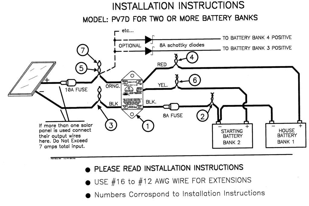
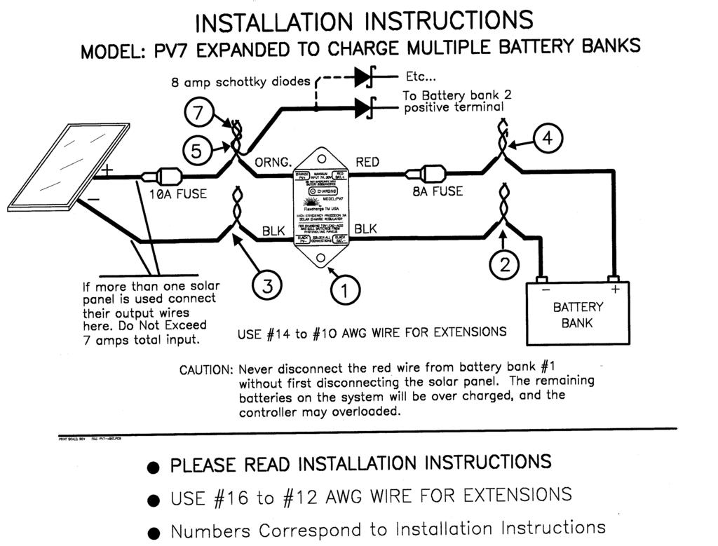
6 FlexchargeTM USA INSTALLATION INSTRUCTIONS PV7, PV7D & PV14D CHARGE CONTROLLERS IMPORTANT When installing the system wiring, make sure all wire connections are making good electrical and mechanical connection. Splice connections should be soldered. Connections that are not made with screw tightened terminals should have anti-oxygen / anti-corrosion coatings applied to the connections before inserting the wires. Note: Step numbers correspond to the numbers in the installation schematics. 1. Choose a good mounting location no more than 10 wired feet from the battery you are charging. Although these controllers have been designed for mounting in semi-harsh locations, mounting them in a more protected environment will help to extend the operational life. 2. Splice a #14 to #10 AWG black wire to the BLACK BAT- WIRE on the controller, and connect it to the BATTERY BANK S negative (-) terminal and/or the system's negative battery bus. If you are using a smart battery fuel meter that measurers total Input to Output Amp/Hours, it will usually have a shunt in the (-) connection to the battery. Connect the (-) wire from the controller to the same terminal as the other loads on the shunt as shown in the meter s manual. 3. Splice a #14 to #10 AWG black wire to the BLACK PV- WIRE on the controller, to the SOLAR PANEL S negative (-) terminal(s). 4. Splice a #14 to #10 AWG red wire to the RED BAT+ WIRE on the controller, and connect it to the BATTERY BANK S positive (+) terminal and/or the system's Positive battery bus. In dual bank systems the Red wire connects to the Primary House Battery bank. For single battery banks systems, a fuse should be installed in the red positive wire. It should be located as close to the battery as possible for the best protection. The Bat+ Fuse is rated at 8A for the PV7 and 15A for the PV Splice a #14 to #10 AWG orange wire to the ORANGE PV+ WIRE on the controller, and connect it to the combined positive (+) output of all the SOLAR PANELS. For added protection and ease of maintenance, we highly recommend that you install a fuse somewhere in the orange PV+ wire. It will provide protection against its accidental connection to a high current source and fully protect the controller. It also will serve as a convenient place to disconnect the charging source from the controller when the battery is removed from the system while the charging source remains active. For Dual Battery Charging Models 6. If you will be using the PV7D s dual battery charging feature, Splice a #14 to #10 AWG yellow wire to the YELLOW BAT(2)+ WIRE on the controller, and connect it to the SECOND BATTERY BANK S positive (+) terminal and/or the second system's positive battery bus. If you will not be using the dual battery charging feature simply tape or place a wire nut over the end of the yellow wire to isolate it electrically and protect it from moisture. Page6
7 Expanding to Charge Additonal Battery Banks (PV7 and PV7D Only) 7. To modify/expand the PV7 and PV7D controllers to charge multiple battery banks please follow these additional steps. a) Obtain the appropriate quantity of 8A 80SQ045 Schottky diodes required for your application (One for each additional battery bank). The Diodes are available from Flexcharge directly, or through our dealers. b) Solder a piece of #16 to #14 AWG stranded wire to each lead on the diode. Excess heat, mechanical stress and electrostatic discharge will damage these diodes. An acceptable alternative to soldering is to connect the diode leads directly into a terminal block that will accept #20 to #12 AWG solid or stranded wire. It must have screw tightened terminals to hold the wires in place. Make sure the diode s leads are insulated and cannot come in contact with other wires, or the ground buss. 8. Additional steps to expand the PV14 for High Ampere charging. A. Obtain the appropriate contactors (relays) from a Flexcharge dealer or Flexcharge directly. B. After mounting the contactor(s) vertically within 50 feet of the PV14 Controller, connect a #20 to #14 AWG wire at the splice where the controller s RED BAT+ wire connects to the wire from the battery s positive terminal. Using the same size wire, connect the opposite end of the wire to the top connection of the contactor(s) 9. Connect the controller s Orange wire to the lower terminals of the contactor(s) If the controller does not function as you think it should, first check the troubleshooting guide in this manual, then call your dealer or Flexcharge USA at the numbers shown below HOOKUP WIRE SIZE CHART This chart provides the minimum wire size to minimize power loss. Larger wires would are always better for operating efficiency Max Charging Capacity WIRE SIZE FOR 1 TO 10FT LENGTHS OA TO 3A #14 AWG #12 AWG 3A TO 6A #12 AWG #12 AWG 6A TO 12A #10 AWG #10 AWG 12A TO 18A #10 AWG #8 AWG WIRE SIZE FOR 10 TO 20FT LENGTHS Page7
8 Solar Panel Blocking Diode Selection Table (One on each solar panel) Ampere Rating Voltage Rating Part Number Type Manufacturer 1A 40V 1N5819 Schottky Diodes Incorporated 3A 40V 1N5822 Schottky International Rectifier 5A 100V 50SQ100 Schottky International Rectifier 8A 45V 80SQ045 Schottky International Rectifier 1A 400V 1N4004 Silicon Diodes Incorporated 3A 400V 1N5404 Silicon Diodes Incorporated 6A 1000V 6A10 Silicon Diodes Incorporated If you cannot find these parts locally, contact Flexcharge USA. All the above diodes are in stock. Controller Specifications (12V) (24V) Parameter MIN. TYP. MAX. MIN. TYP. MAX. INPUT VOLTAGE (BAT or PV) 0V - 30V 0V - 50V PROGRAMMED OVERSHOOT V V VOLTAGE (MICRO - EQUALIZATION) CHARGING CURRENT PV14 PV7 4mA 4mA A 8A 4mA 4mA A 8A PV7D Must not exceed 8A total input current CONTROLLER STANDBY CURRENT 2mA 2.6mA 3mA 2mA 2.6mA 3mA (NIGHT) CONTROLLER STANDBY CURRENT 4mA 5mA 6mA 4mA 5mA 6mA (Charging) CHARGE DISCONNECT VOLTAGE 14.20V 14.25V 14.30V 28.40V 28.50V 28.60V (Regulation Voltage) CHARGE RECONNECT VOLTAGE 13.50V 13.60V 13.70V 27.00V 27.20V 27.40V VOLTAGE DROP ACROSS 0.2V 0.4V 0.56V 0.2V 0.4V 0.56V CONTROLLER TRANSIENT SURGE SUPPRESSION W W HUMIDITY 5% - 100% 5% - 100% OPERATING TEMPERATURE -40 C 25 C 60 C -40 C 25 C 60 C MTBF (Mean Time Between Failures) Years Years CASE SIZE H=1.2 W=4.75 L=3.0 Page8

9 Figure 1: Figure 2: Page9

10 Figure 3: Figure 4: Page10

11 Figure 5: Page11
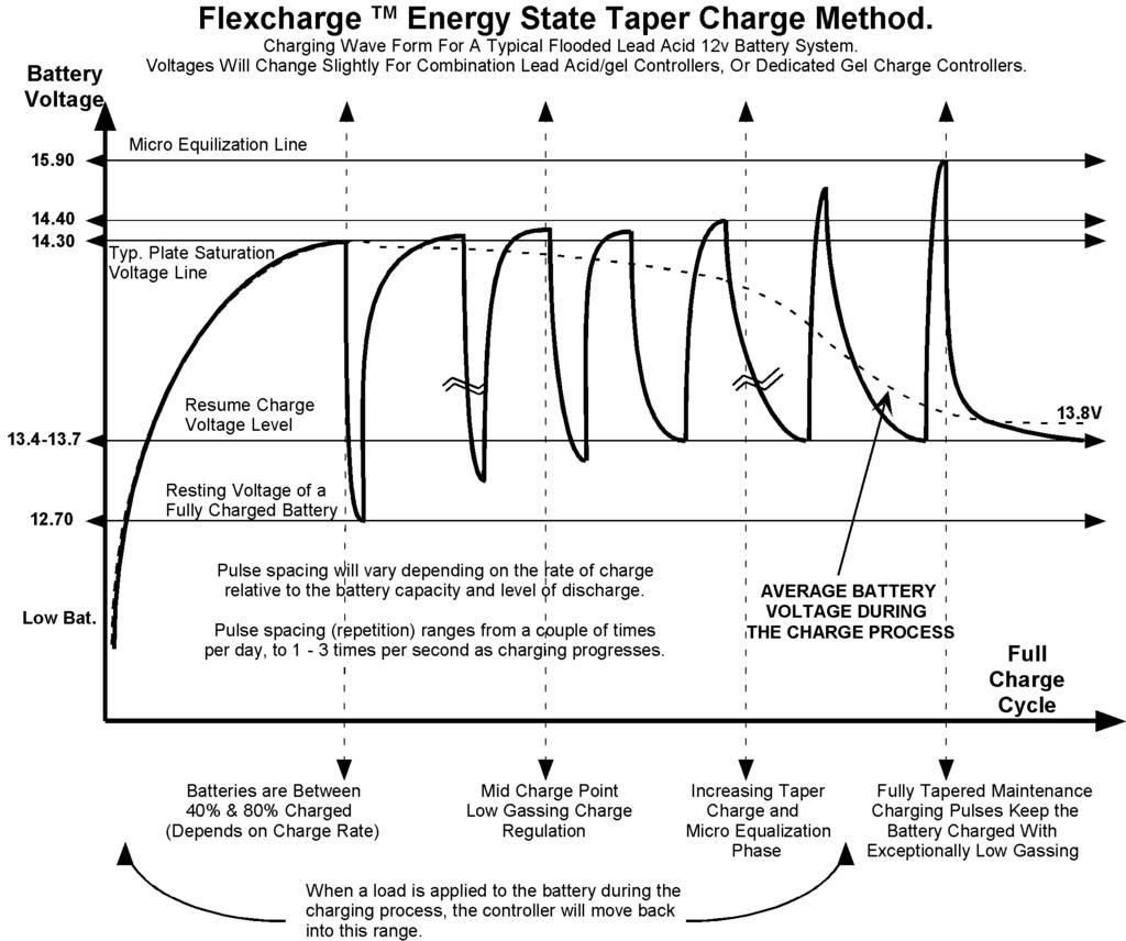
12 The Flexcharge TM Energy State Taper Charge Process Monitors the battery for the full charged resting voltage of the cells. Discover the tremendous advantages using controllers with this charge method. Zero overcharging Exceptionally low gassing (Up to 90% less) No RFI or EMI emissions to interfere with radio equipment. Non-Destructive Micro-Equalization at each full charge The chemical processes of the battery actually control the charging. The need for temperature compensation is also greatly reduced because the plate voltage is not held constantly at the critical plate saturation voltage. Voltage Tapering is controlled by the battery's level of charge rather than with timers, or fixed voltages as in PWM and other constant voltage charge methods. The battery takes exactly what it needs rather than being forced to take a set voltage. With the Flexcharge method, you can charge your battery bank indefinitely without any possibility of overcharging. The batteries will last longer, require less watering maintenance, and hold a better charge. As charging begins the controller allows full charging current to pass directly to the battery. When the battery voltage rises slightly above the plate saturation point, the controller opens the charging circuit. Much like a sponge will continue to absorb water towards its center after it has taken it all into its surface, the chemical charging process continues after the charging current has been removed. As the charge is absorbed, the battery's voltage will fall. When the battery voltage has floated down to approximately 13.5V to 13.8V it is ready to accept another charge pulse. This charge regulation method is actually controlled by the battery's ability to accept and absorb energy. When the battery needs more energy indicated by plate voltage, the controller applies it. Mid way in the charging process, the controller will cycle ON and then OFF sending full charge current pulses into the plates. This process charges with very low gassing, and equalizes the plates with each full charge. As the battery reaches a higher level of charge, the amount of time the controller spends in charge is reduced, and the time in rest is increased. At full charge, the controller will apply short duration pulses to maintain the battery at an average voltage of about volts. This keeps gassing to a minimum while effectively trickle charging, and equalizing at the same time. There has been a great deal of discussion over which charge process is better, PWM, or this method. To add fuel to the fire, each company making "ON-OFF" controllers has chosen different voltages to set the disconnect and reconnect points. A number of PWM controller manufacturers have gone to great lengths to discredit Low Frequency PWM or ON-OFF regulators by studying a controller that was not set up with the proper connect/reconnect voltages. At Flexcharge we have analyzed controllers using a version of this method where the reconnect voltage on a 12V system was set at 70 F. On this system the batteries would never see more than 80% charge, and likely much less. Obviously PWM type controllers will regulate the charging of your batteries. With proper temperature compensation, heat sinks, and the correct Bulk-Regulate-Float (3 stage) algorithm will do a pretty good job of it, but why settle for this when you can get so much more in a charge regulator. Instead of three stages with PWM you get an infinitely variable charge process which will supply the battery with exactly what it needs, only when it needs it. You will realize less plate saturation gassing, non-destructive equalization and Zero EMI and RFI as well. Electrico-Magnetic- Interference, and Radio Frequency Interference is electronic noise that can interfere with radio and navigation equipment. Charge Controllers using the Energy State Taper Charge are best suited for charging systems where the charging current is less than 1/4 of the amp hour rating of the battery bank. If your charging system is designed to charge at a rate higher than 1/4 the battery bank's capacity, then the power switching element should be solid state to provide the longer term reliability. At Flexcharge we make use of both types of switching elements in our controllers depending on the task. They are implemented in such a way as to provide exceptional levels of dependability. To determine these ratings, first add up the total amp/hour capacity of your battery bank then divide that number by 4. If the result is larger than the maximum current your charging source can produce, then the Energy State Taper Charge Process is the best method for your system. Page12
13 Page13
14 Please Read!! IMPORTANT: USING or NOT USING BLOCKING DIODES ON YOUR PV CHARGING SYSTEM? There has been a great deal of discussion in the solar electric (Photovoltaic) industry over the use of blocking diodes. In an effort to clarify the confusion Flexcharge TM USA has called, met with, or gathered information pertaining to this topic from the following solar panel and equipment manufacturers; Seimiens, Astro Power, United Solar, & Solarex. The following is a condensed version of the information to assist you in designing a failure resistant system. What is a blocking diode? A blocking diode is a one way valve for electricity. The band on the case of the diode is the output, which should be installed towards the battery in the positive wire from each solar panel. There are two primary types of diodes, Schottky (sensitive to damage but low loss type) and Silicon (tough, but higher loss). They are rated by the amount of current that can pass through them in amps, and the amount of voltage they can withstand backwards. What is the function of blocking diodes in a Photovoltaic (PV) system? 1 To prevent the flow of electricity into the panels when the panels are not making electricity, and to prevent voltage spikes in the system from reaching the panels, 2 To prevent a damaged panel which has shorted (a common type of failure) from draining the battery system, or drawing power from the remaining good panels. There are the three popular types of solar electric panel technologies being used today. 1) SINGLE CRYSTALLINE 2) POLY CRYSTALLINE 3) AMORPHOUS How should blocking diodes be used with each type of panel? SINGLE CRYSTALLINE panels are glass covered rigidly mounted panels. They have a low nighttime back flow of power from the batteries. The loss at night is actually a little less than the amount of loss you get by adding a blocking diode to the panel. You will get more out of your panel if you do not using blocking diodes on these type of panels, BUT!! on multiple panel arrays, blocking diodes should be used, especially on unattended remote systems, to guard against a failed panel. Because they are glass covered, a stray falling branch, hail stones, a child with a rock, or bored hunter could bring the entire system down by damaging only one panel. Diodes help protect the rest of the system from these events. POLY CRYSTALLINE panels are also glass covered rigidly mounted panels. They have a slightly higher nighttime draw of power from the batteries when compared to single crystalline panels. The loss at night is near equal to the loss you get by adding a blocking diode to the panel. You may or may not get more out of your panel by using blocking diodes on these type of panels, BUT!! on multiple panel arrays, blocking diodes should be used, especially on unattended remote systems, to guard against a failed panel. Because they are glass covered, a stray falling branch, hail stones, a child with a rock, or bored hunter could bring the entire system down by damaging only one panel. Diodes help protect the rest of the system from these events. AMORPHOUS panels are a very different when compared to the other types of panels. They have a fairly substantial nighttime draw of power from the batteries when compared to single crystalline panels. The loss at night is higher than the loss you get by adding a blocking diode to the panel; in addition, these type panels will actually draw enough power from the batteries at night to damage themselves if diodes are not used. To compensate for the diode loss, most amorphous panels are designed to have a higher operating voltage, which compensates for the voltage drop losses of the diode. Blocking diodes should be used on all systems when panels have been connected in series to charge 24V, or higher voltage batteries, or when using an inverter on the system. Inverters can cause voltage spikes as high as 60 volts on the DC system. This is enough voltage to damage most solar panels. In conclusion; blocking diodes should be used on all systems except, one panel single crystalline 12V systems. If your system is so marginal that using, or not using diodes will make the difference, consider adding another solar panel to your system. Page14
15 Flexcharge TM CHARGE CONTROLLER TROUBLESHOOTING GUIDE IF YOU ARE USING CRIMP ELECTRICAL CONNECTORS IN YOUR SYSTEM WIRING, THEY SHOULD HAVE BEEN SOLDERED, OR TREATED WITH AN ANTI-OXIDIZING COMPOUND. WITHOUT THESE STEPS CRIMP CONNECTIONS WILL ONLY MAKE GOOD CONNECTION FOR A SORT PERIOD OF TIME, ESPECIALLY IN A MARINE OR OUTDOOR ENVIRONMENT. PROBLEM CONTROLLER IS NOT CHARGING WHEN THE PANEL IS MAKING POWER Or CHARGE INDICATOR IS PULSING EVERY SECOND OR SO SOLUTIONS 1. Check the fuse. If necessary, replace it with an 8A fuse for the PV7, or a 15A fuse for the PV14. Never install a fuse larger than these ratings. The controller could be damaged. 2. Check the fuse and wire connections between the controller and the battery. A poor connection here will cause this symptom. 3. If you connected the regulator to your battery selector switch, make sure the switch is NEVER in the OFF position. Just as your engine alternator cannot be run when the battery switch which is turned OFF, neither can most solar charge regulators. THE CHARGING LIGHT IS OFF WHEN THE SOLAR PANEL IS MAKING POWER If the battery is being charged by another charging source (i.e. alternator, shore battery charger or wind generator) the battery may be near its peak voltage. In these circumstances the controller is sensing that battery does not need the charging current from the solar panels and the light will be OFF. If however the battery voltage is below 13.6V (27.2V on 24V systems) and the solar panel is making power, the controller's charge light should be ON. Check the wire connections between the solar panels and the controller. THE SOLAR PANEL'S OUTPUT VOLTAGE DROPS TO ALMOST THE SAME AS THE BATTERY VOLTAGE WHEN IT IS CHARGING THE SOLAR PANEL VOLTAGE MEASURES NEARLY ZERO VOLTS WHEN IT SEEMS IT SHOULD BE CHARGING THIS IS NORMAL. Except for voltage differences caused by losses in the wiring, the voltage in the charging system will always be the same no mater where you measure it. When the panel s positive wire is disconnected from the controller its voltage can then rise to its natural open circuit voltage for solar panels of 16V to 22V (For 12V Systems). NOTE: The battery voltage will not instantly come up to 14.3V when it is being charged unless the charging source has enough charging current capacity (50 amps or so) to push them there very quickly. You will usually see a slowly rising voltage dependent on the amount of charging current generated by your solar panel(s). THIS IS NORMAL IF THE CHARGE INDICATOR LED IS OFF, AND THE BATTERY VOLTAGE IS ABOVE 13.6V, (27.2V on 24V systems) after the batteries have reached the disconnect voltage. The Solar Panel s Voltage will cycle between near battery voltage and zero volts with the charge indicator light. See "Energy State Charge Process" for and explanation of the charge regulation process. When the light is ON the Solar panel voltage will be about the same as the battery voltage. When it's OFF it will be near zero volts. Page15
16 THE CONTROLLER IS GETTING VERY WARM 1. Make sure the controller is connected to the battery by checking the wiring or fuse. 2. Measure your charging current to make sure it is less than 8A (PV7) or 15A (PV14) on the PV+ side of the controller. To check charging current, remove the fuse and insert the amp meter in its place. When the charging light is on, view the amp meter It is a good idea to install a fuse in the orange wire (PV+) side of the controller. THE CHARGE INDICATOR NEVER COMES ON Remove the fuse when the panel is charging (in the sun) and first, view the charge indicator. It should be pulsing every second or so. Next, install an amp meter with a 20A rating in place of the fuse to check if the controller is passing the current being made by the panel, to the batteries. If the light is not ON, the battery voltage is less than 13.4V, the wire connections are good and current is not flowing the controller has probably failed. THE BATTERY IS BEING OVER- CHARGED Ensure that the batteries are not being charged by another source. If the battery voltage is constantly over 14.4V, the charge light is ON and the batteries are not being charged by another source then the controller may have failed. Remove the fuse. While the solar panels are producing power the controller s charge light should be flashing every second or so. If the charge indicator is not flashing, it is likely that the controller has failed. Flexcharge TM USA PRODUCT WARRANTY Flexcharge USA products are warranted for a period of two years (five years on NC series charge controllers, and one year on lighting products) from the date of purchase, subject to the conditions set forth below, to the original purchaser to be free from material and workmanship defects. During the warranty period, the product will be repaired or replaced, at the option of Flexcharge USA, free of charge. Products from other manufacturers that are incorporated into Flexcharge USA products such as solar panels and batteries, are covered by warranties from those manufactures. CONDITIONS 1. Proper delivery: The product must be packed to prevent damage and shipped to Flexcharge USA, 1217 State St., Charlevoix, MI USA, freight prepaid and including: a. Proof of purchase. ( invoice showing product and date ) b. Description of problem. 2. Abuse, misuse, negligence, unauthorized repairs: The warranty is void if any defects are caused by abuse, misuse, negligence, or unauthorized repairs. Damage caused by lightning is considered an act of God and is not warranted. 3. All liability for incidental or consequential damages is specifically excluded. Some states do not allow the exclusion or limitation of incidental or consequential damages so the above limitation or exclusion may not apply. Page16
Model NCHC-xx Owners Manual
 Model NCHC-xx Owners Manual Ultra High Efficiency Industrial Grade, High Ampere, Alternative Energy Battery Charge Controller MODEL: NCHC-12, 24, 36, 48 For GEL, AGM, and Flooded Cell Lead Acid Batteries
Manual Installation & Operation
 Manual Installation & Operation Model: NCxxLxx 12A or 30A Solid State Solar Charging Regulator and 12A Load Controller. 231 Patent #: 5,642,030 Applies Page 1 Warnings When Installing, connect grounds,
Owner s Manual. Contents GP-PWM-10-SQ
 Owner s Manual Contents 1.0 Installation Overview... 2 2.0 Warnings... 2 3.0 Choosing a Location... 3 4.0 Installation Instructions... 3 5.0 Operating Instructions... 4 6.0 Frequently Asked Questions (FAQs)...
Owner s Manual. Contents GP-PWM-30-SQ GP-PWM-30-SQ
 Owner s Manual Contents 1.0 Installation Overview... 2 2.0 Warnings... 2 3.0 Choosing a Location...3 4.0 Installation Instructions... 3 5.0 Operating Instructions...4 6.0 Frequently Asked Questions (FAQs)...6
LS0512 Solar Charge Controller
 LandStar LS0512 Solar Charge Controller Nominal system voltage Maximum PV input voltage Nominal charge / discharge current 12VDC 35V 5A Contents 1 Important Safety Information... 1 2 General Information...
PHOTO VOLTAIC CHARGE MODULE MULTI POINT TRACKING
 FEATURES Multi Point Tracking (MPT)/ Pulse Width Modulation (PWM) is a six stage solar charge controller. Drop-in PWM replacement for the PVCM-25D two stage solar charge controller. Works with the PVDM4-LC,
LS0512R Solar Light Controller
 LandStar LS0512R Solar Light Controller Nominal system voltage Maximum PV input voltage Nominal charge / discharge current 12VDC 35V 5A Contents 1 Important Safety Information... 1 2 General Information...
Solar Controller GP-PWM-30. Owner s Manual Go Power! By Valterra Power
 Solar Controller GP-PWM-30 Owner s Manual 1 2 CONTENTS 1.0 Installation Overview 4 1.1 Introduction 4 1.2 Specifications 5 2.0 Warnings 6 3.0 Tools and Materials Needed 7 4.0 Choosing a Location 7 5.0
PV Charge Controller SBC-7108 / 7112 / 7120
 PV Charge Controller SBC-7108 / 7112 / 7120 User's Manual NOTE: Please note that features like LCD read out of AH logging of 3 days (see Section 3.3) and 10 Night-light mode (see Section 4.3) are available
Owner s Manual. Solar Controller GP-PWM-30
 Owner s Manual Solar Controller GP-PWM-30 1.0 Installation Overview 1.1 Introduction A Solar Controller (or Charge Controller / Regulator) is an essential component of your photovoltaic solar system. The
Harness the Power of the Sun
 Harness the Power of the Sun Solar Controller / Battery Charger User s Manual Nominal Voltage: 12Volts Rated Solar Current: 30Amps / 40Amps Nominal Voltage: 12Volts / 24Volts Auto Rated Solar Current:
The Traveler Series: Wanderer
 The Traveler Series: Wanderer RENOGY 30A PWM Charge Controller Manual 2775 E. Philadelphia St., Ontario, CA 91761 1-800-330-8678 1 Version: 2.3 Important Safety Instructions Please save these instructions.
PV Charge Controller SBC-6108 / 6112 / 6120 / 6130
 PV Charge Controller SBC-6108 / 6112 / 6120 / 6130 User's Manual Table of Contents Precautions and Specifications 1 1. Introduction 2 2. Control and Indicator 2 3. Installation and Indication 3 3.1 Connection
AUTO CHARGE D PUMP PLUS
 INSTRUCTION MANUAL AUTO CHARGE D PUMP PLUS AUTOMATIC DUAL OUTPUT BATTERY CHARGER Designed Specifically for Vehicles with DDEC ENGINES MODEL #: 091-9-DPP INPUT: 120 Volt, 60 Hz, 8 Amps OUTPUT VEHICLE BATTERY:
Reference: Photovoltaic Systems, p References: Photovoltaic Systems, Chap. 7 National Electrical Code (NEC), Articles 110,
, Articles 110,") Charge controllers are required in most PV systems using a battery to protect against battery overcharging and overdischarging. There are different types of charge controller design, and their specifications
Charge controllers are required in most PV systems using a battery to protect against battery overcharging and overdischarging. There are different types of charge controller design, and their specifications
AUTO CHARGE D2 MODEL #: AUTOMATIC TRIPLE OUTPUT BATTERY CHARGER INSTRUCTION MANUAL
 INSTRUCTION MANUAL AUTO CHARGE D2 AUTOMATIC TRIPLE OUTPUT BATTERY CHARGER Designed Specifically for Vehicles with DDEC ENGINES MODEL #: 091-74-12 INPUT: 120 Volt, 60 Hz, 8 Amps OUTPUT VEHICLE BATTERY 1
Installation and Operation Manual. Dual Battery Charging Solar Controller. for RVs, Caravans, and Boats. Ratings. Rated Solar Current 25 Amps
 SUNSAVER DUO TM Installation and Operation Manual. Dual Battery Charging Solar Controller for RVs, Caravans, and Boats.. Ratings Nominal Voltage 12 Volts Rated Solar Current 25 Amps 1098 Washington Crossing
Eclipse Solar Suitcase
 Eclipse Solar Suitcase Renogy 100W 200W 2775 E. Philadelphia St., Ontario, CA 91761 1-800-330-8678 Version 1.0 Important Safety Instructions Please save these instructions. This manual contains important
PHOTOVOLTAIC SYSTEM CONTROLLERS SUNSAVER MODELS INCLUDED IN THIS MANUAL SS-6 / SS-6L SS-10 / SS-10L SS-10-24V / SS-10L-24V SS-20L SS-20L-24V
 PHOTOVOLTAIC SYSTEM CONTROLLERS OPERATOR S MANUAL SUNSAVER MODELS INCLUDED IN THIS MANUAL SS-6 / SS-6L SS-10 / SS-10L SS-10-24V / SS-10L-24V SS-20L SS-20L-24V 6A / 12V 10A / 12V 10A / 24V 20A / 12V 20A
The Traveler Series: Wanderer
 The Traveler Series: Wanderer RENOGY 30A Charge Controller Manual 2775 E. Philadelphia St., Ontario, CA 91761 1-800-330-8678 Version: 2.0 Important Safety Instructions Please save these instructions. This
Models DP10 & DP20 Series Low Voltage Disconnects User s Manual Rev. 1.1 October 31, 2007
 B R A N D Models DP10 & DP20 Series Low Voltage Disconnects User s Manual Rev. 1.1 October 31, 2007 For Sales, Support and Service phone: 407-331-4793 fax: 407-331-4708 website: www.xenotronix.com email:
Digital echo-charge. Owner s Manual. Xantrex Digital echo-charge Battery Charger
 Digital echo-charge Owner s Manual Xantrex Digital echo-charge Battery Charger INTRODUCTION The Xantrex Digital echo-charge is specially developed for charging an auxiliary battery with Freedom TM or Fleet
12 VOLT 30 AMP DIGITAL SOLAR CHARGE CONTROLLER
 12 VOLT 30 AMP DIGITAL SOLAR CHARGE CONTROLLER User s Manual Congratulations on your Coleman solar product purchase. This product is designed to the highest technical specifications and standards. It will
LS1024BP/ LS2024BP. Solar Charge Controller USER MANUAL
 EPSOLAR LS1024BP/ LS2024BP Solar Charge Controller USER MANUAL Thank you very much for selecting our product! This manual offers important information and suggestions with respect to installation, use
RUTLAND HRDi CHARGE REGULATOR INSTALLATION AND OPERATION
 RUTLAND HRDi CHARGE REGULATOR INSTALLATION AND OPERATION Introduction Congratulations and thank you for purchasing Marlec s HRDi Charge Regulator. This is the latest technology for charge regulation of
Instruction Manual. Duo-battery Solar Panel Controller EPIP20-DB series For Both 10 and 20 amp. Controllers (for use with solar panels only) + -
 + -") Instruction Manual Duo-battery Solar Panel Controller EPIP20-DB series For Both 10 and 20 amp. Controllers (for use with solar panels only) + - Optional - Switch to disconnect solar panel when engine alternator
Instruction Manual Duo-battery Solar Panel Controller EPIP20-DB series For Both 10 and 20 amp. Controllers (for use with solar panels only) + - Optional - Switch to disconnect solar panel when engine alternator
QSSE, QSSEX INDUSTRIAL Battery Chargers
 C O R P O R A T IO N O P E R A T I N G I N S T R U C T I O N S QSSE, QSSEX INDUSTRIAL Battery Chargers INTRODUCTION The QSE line are electronically controlled float chargers. The batteries are brought
GP-MPPT-40. User Manual Go Power!
 User Manual Contents 1.0 Installation Overview 3 1.1 Introduction 3 1.2 Specifications 4 2.0 Warnings 5 3.0 Tools and Materials Needed 5 4.0 Choosing a Location 6 5.0 Choosing an Array 6 6.0 Installation
MANUAL D250SA SMARTPASS 120. Input Solar panel Earth Connection
 MANUAL CONGRATULATIONS on the purchase of your new CTEK charger providing professional battery care. This charger is included in a series of professional chargers from CTEK SWEDEN AB and represents the
LS1024R / LS1524R / LS2024R. Solar Light Controller INSTRUCTION MANUAL
 EPSOLAR Design patent NO.: 201130028317.3 Utility model patent NO.: 201120064092.1 LS1024R / LS1524R / LS2024R Solar Light Controller INSTRUCTION MANUAL Thank you very much for selecting our product! This
AUTO CHARGE 4000 MODEL #: AUTOMATIC DUAL OUTPUT BATTERY CHARGER INSTRUCTION MANUAL. Ph: Fax:
 INSTRUCTION MANUAL AUTO CHARGE 4000 AUTOMATIC DUAL OUTPUT BATTERY CHARGER MODEL #: 091-89-12 INPUT: 120 Volt, 50/60 Hz, 8 Amps OUTPUT BATTERY CHARGER: 40 Amps OUTPUT BATTERY SAVER: 5 Amps File: IM_091-89-12_reve.indd
PUMP PLUS 1000 PLC MODEL #: PP AUTOMATIC SINGLE OUTPUT BATTERY CHARGER INSTRUCTION MANUAL
 INSTRUCTION MANUAL PUMP PLUS 1000 PLC AUTOMATIC SINGLE OUTPUT BATTERY CHARGER Unit supplied with one of these displays MODEL #: 091-215-12-PP INPUT: 120 Volt, 60 Hz, 3.5 Amps OUTPUT BATTERY 1 and 2: 15
GP-PWM-10. User Manual Carmanah Technologies Corporation
 User Manual 2 Contents 1.0 Installation Overview 4 1.1 Introduction 4 1.2 Specifications 5 2.0 Warnings 6 3.0 Tools and Materials Needed 6 4.0 Choosing a Location 7 5.0 Installation Instructions 7 6.0
10A / 15A / 20A Solar Charge Controller. PU1024 / PU1524 / PU2024 series INSTRUCTION MANUAL
 10A / 15A / 20A Solar Charge Controller PU1024 / PU1524 / PU2024 series INSTRUCTION MANUAL Dear Customer, Thank you very much for choosing our product. This manual contains important information about
LIGHTNING PROTECTION UNIT (LPU)
") LIGHTNING PROTECTION UNIT (LPU) Photovoltaic Lightning Protection Device Installation and Operation Manual SPECIALTY CONCEPTS, INC. 8954 Mason Ave. Chatsworth, CA 91311 USA MODELS COVERED: LPU-50, LPU-150,
LIGHTNING PROTECTION UNIT (LPU) Photovoltaic Lightning Protection Device Installation and Operation Manual SPECIALTY CONCEPTS, INC. 8954 Mason Ave. Chatsworth, CA 91311 USA MODELS COVERED: LPU-50, LPU-150,
Solar Controller / Battery Charger User s Manual
 Solar Controller / Battery Charger User s Manual 1 Congratulations! You have made an excellent choice by purchasing this high quality KORR PWM solar controller which has been manufactured to the highest
NSTHAI. Solar Light Controller
 NSTHAI Design patent NO.: 201130028317.3 Utility model patent NO.:201120064092.1 NSC2024R (LS2024R) Solar Light Controller INSTRUCTION MANUAL Thank you very much for selecting our product! This manual
SOLAR LIGHTING CONTROLLER SUNLIGHT MODELS INCLUDED IN THIS MANUAL SL-10 SL-10-24V SL-20 SL-20-24V
 SOLAR LIGHTING CONTROLLER OPERATOR S MANUAL SUNLIGHT MODELS INCLUDED IN THIS MANUAL SL-10 SL-10-24V SL-20 SL-20-24V 10A / 12V 10A / 24V 20A / 12V 20A / 24V 1098 Washington Crossing Road Washington Crossing,
Super PWRgate PG40S Spring City Drive Waukesha, WI
 Super PWRgate PG40S www.westmountainradio.com 1020 Spring City Drive Waukesha, WI 53186 262-522-6503 sales@westmountainradio.com 2015, All rights reserved. All trademarks are the property of their respective
Smart Battery Charger GPC-35-MAX GPC-45-MAX GPC-55-MAX GPC-75-MAX GPC-100-MAX. Owner s Manual
 Smart Battery Charger GPC-35-MAX GPC-45-MAX GPC-55-MAX GPC-75-MAX GPC-100-MAX Owner s Manual Table of Contents Important Safety Instructions 2 Features 3 Installation Guidelines 5 Warranty 8 1.0 Important
KIT-STCS60D KIT-STCS100D Solar Suitcase 60W and 100W Owner s Manual
 KIT-STCS60D KIT-STCS100D Solar Suitcase 60W and 100W Owner s Manual RNG Group Inc. (Renogy) 14288 Central Ave., Suite A Chino, CA 91710 1-800-330-8678 Product Description The Renogy Solar Suitcases combine
PUMP PLUS 2000 PLC MODEL #: PP AUTOMATIC DUAL OUTPUT BATTERY CHARGER INSTRUCTION MANUAL
 INSTRUCTION MANUAL PUMP PLUS 2000 PLC AUTOMATIC DUAL OUTPUT BATTERY CHARGER Supplied with Dual Bar Graph Display MODEL #: 091-237-12-PP INPUT: 120 Volt, 60 Hz, 3.5 Amps OUTPUT BATTERY 1 and 2: 15 or 18
CONGRATULATIONS ON YOUR PURCHASE OF YOUR THUNDER BATTERY CHARGER! For your personal safety read, understand and follow the information provided in
 CONGRATULATIONS ON YOUR PURCHASE OF YOUR THUNDER BATTERY CHARGER! For your personal safety read, understand and follow the information provided in this instruction manual & on the battery charger. This
O P E R A T I N G I N S T R U C T I O N S
 O P E R A T I N G I N S T R U C T I O N S Select-A-Charge Battery Chargers models: SCP, SCPX, SCS, SCSX, SCX For Industrial Use: Designed for gel, wet cell, AGM, and Lithium Ion batteries (Lithium ion
EV Power - Battery Control Unit Instructions. 8 Cell 24V
 EV Power - Battery Control Unit Instructions. 8 Cell 24V PAGE 1 OF 12 BCU-EVPPAK Features - Simple to install and use, microprocessor control. - Low power requirement, just 15mA when switched on with relay
Solar Controller GP-PWM-30. Owner s Manual
 Owner s Manual 1 2 CONTENTS 1.0 Installation Overview 4 1.1 Introduction 4 1.2 Specifications 5 2.0 Warnings 6 3.0 Tools and Materials Needed 7 4.0 Choosing a Location 7 5.0 Installation Instructions 8
OBAE, OBAEXU, ON BOARD Battery Chargers
 C O R P O R A T IO N O P E R A T I N G I N S T R U C T I O N S OBAE, OBAEXU, ON BOARD Battery Chargers INTRODUCTION: The OBAE line of chargers are designed for the permanent installation on battery powered
USER MANUAL Seabourne Solutions LLC
 Kiss Extractor TM USER MANUAL Seabourne Solutions LLC Introduction Developing Enhancing Products Congratulations on purchasing a Kiss Extractor TM. The Extractor TM has several advantages when used to
MPPT75HV MAXIMUM POWER POINT TRACKING SOLAR BATTERY CHARGE CONTROLLER
 MPPT75HV MAXIMUM POWER POINT TRACKING SOLAR BATTERY CHARGE CONTROLLER The Intronics Power Inc. MPPT75HV Solar Charge Controller continually tracks the maximum power point of the solar panel array, adjusting
3400W Solar Battery Charger Maximum Power Point Tracker
 Page 1 of 8 A simple, compact low cost MPPT to efficiently charge lead acid and lithium iron batteries from a wide range of photovoltaic panels. The MPPT 60-2 is designed to charge lead acid and lithium
1700W Solar Battery Charger Maximum Power Point Tracker
 Page 1 of 8 A simple, compact low cost mppt to efficiently charge lead acid and lithium iron batteries from a wide range of photovoltaic panels. The is designed to charge lead acid and lithium batteries
RU BMS Power Supply and Battery Management System Owners Guide
 RU2-4012- BMS Power Supply and Battery Management System Owners Guide (These instructions are intended for use by a technician familiar with electronic products) RU2-4012- BMS is a continuous duty power
10 Year Limited Warranty
 Power. On Your Terms. 10 Year Limited Warranty PHI 2.7 TM PHI 3.5 TM 60A SIMPLIPHI POWER, INC. REV020618 10 Year Limited Warranty: PHI 2.7 TM PHI 3.5 TM 60A 24V 48V Limited Pro-Rated Warranty Coverage
Art. No. EC-315. Art. No. EC-330. Art. No. EC-340 SWITCH-MODE BATTTERY CHARGER CONTENTS IMPORTANT SAFETY PRECAUTIONS... 2
 SWITCH-MODE BATTTERY CHARGER CONTENTS IMPORTANT SAFETY PRECAUTIONS... 2 DESCRIPTION AND FEATURES... 3 CHARGING STAGES... 4 Art. No. EC-315 Art. No. EC-330 Art. No. EC-340 PROTECTIONS... 5 INSTALLATION...
SCC-MPPT Solar Charge Controller
 Table 3: Charging voltage for 4 types of battery Battery Battery 12V battery system 24V battery system Type Type Code Bulk Floating Bulk Floating Vented 01 14.3 V 13.2 V 28.6 V 26.4 V Sealed 02 14.3 V
LS1024BP/ LS2024BP. Solar Charge Controller USER MANUAL
 EPSOLAR LS1024BP/ LS2024BP Solar Charge Controller USER MANUAL Thank you very much for selecting our product! This manual offers important information and suggestions with respect to installation, use
12 VOLT SOLAR PANEL KITS MONOCRYSTALLINE. P/No. SPP160K
 12 VOLT SOLAR PANEL KITS MONOCRYSTALLINE P/No. SPP160K WARNING SOLAR PANEL For installations with lead acid batteries, avoid sparks or flames near the batteries and always use proper eye protection Given
2603 Battery Pal 3 AMP, 1 2 VOLT BATTERY CHARGER
 R 2603 Battery Pal 3 AMP, 1 2 VOLT BATTERY CHARGER Connections at a glance: The GUEST Battery Pal 2603 is designed to recharge your battery, and extend your battery s life in applications where it is stored
3400W Solar Battery Charger Maximum Power Point Tracker
 Page 1 of 8 A simple, compact low cost MPPT to efficiently charge lead acid and lithium iron batteries from a wide range of photovoltaic panels. Unit PATENT APPLIED FOR - 2010901565 Unit 2, 110 Station
Automatic Battery Charger Switching mode with Micro-controlled Input: Vac / Output: 12Volt DC
 Automatic Battery Charger Switching mode with Micro-controlled Input:220-260Vac / Output: 12Volt DC User s Manual and Important Safety Information Model: OC-SW121080 / OC-SW121160 / OC-SW121210 FEATURES
OBE, OBEXU, ON BOARD Battery Chargers
 C O R P O R A T IO N O P E R A T I N G I N S T R U C T I O N S OBE, OBEXU, ON BOARD Battery Chargers INTRODUCTION: These chargers are designed for the permanent installation on battery powered vehicles
Portable Solar Kits. User Manual GP-PSK-80 GP-PSK-120
 Portable Solar Kits User Manual GP-PSK-80 GP-PSK-120 2015 Go Power! By Valterra Products, LLC Worldwide Technical Support and Product Information gpelectric.com Go Power! 201-710 Redbrick St, Victoria,
Coleman Air Diversion Controller Model C40
 Coleman Air Diversion Controller Model C40 Version 2.0 With Extended Diversion Mode Designed for 12 volt battery based systems. The Coleman Air model C40 charge controller is a compact, simple to use controller
LPC 40 MODEL #: LOW PROFILE CHARGER WITH PLC AUTOMATIC SINGLE OUTPUT BATTERY CHARGER INSTRUCTION MANUAL
 INSTRUCTION MANUAL LPC 40 LOW PROFILE CHARGER WITH PLC AUTOMATIC SINGLE OUTPUT BATTERY CHARGER Unit supplied with one of these displays MODEL #: 091-200-12 INPUT: 120 Volt, 50/60 Hz, 5 Amps OUTPUT: 40
AUTO CHARGE 4000 MODEL #: LOW PROFILE CHARGER AUTOMATIC DUAL OUTPUT BATTERY CHARGER INSTRUCTION MANUAL
 INSTRUCTION MANUAL AUTO CHARGE 4000 LOW PROFILE CHARGER AUTOMATIC DUAL OUTPUT BATTERY CHARGER Unit supplied with this display MODEL #: 091-89-12 INPUT: 120 Volt, 50/60 Hz, 5 Amps OUTPUT: 45 Amps File:
Power. On Your Terms.
 Power. On Your Terms. 10 YEAR LIMITED WARRANTY PHI 1310 TM 1 SIMPLIPHI POWER, INC. REV102016 10 YEAR LIMITED WARRANTY: PHI 1310 TM LIMITED PRO-RATED WARRANTY COVERAGE The SimpliPhi Power PHI 1310 as supplied
MBCM-24 MULTIPLE BATTERY CHARGING MODULE (FOR MARINE APPLICATIONS) FEATURES SPECIFICATIONS APPLICATIONS DESCRIPTION & OPERATION ORDERING INFORMATION
 FEATURES SPECIFICATIONS APPLICATIONS DESCRIPTION & OPERATION ORDERING INFORMATION") FEATURES Extends the trolling motor run time by charging the trolling motor batteries each time the boat s main engine is used. Automatically senses engine s alternator charge voltage, connects trolling
FEATURES Extends the trolling motor run time by charging the trolling motor batteries each time the boat s main engine is used. Automatically senses engine s alternator charge voltage, connects trolling
400W Solar Charger Maximum Power Point Tracker
 MPPT2-2P Page of 8 This revolutionary maximum power point tracker solar charger was designed using the technology that won GSL Electronics the prestigious 2008 EDN Innovation award. A simple, compact and
SMPPT. Solar Charge Controller with Maximum Power Point Tracking. Installation & Operation Manual
 SMPPT Solar Charge Controller with Maximum Power Point Tracking 10A/20A/30A 12V/24V Installation & Operation Manual 1 Dear Consumer: Thank you very much for using our product! We will offer you the permanent
TECHNICAL NOTE #4 Revised May 24, BOGART ENGINEERING Two Bar Road, Boulder Creek, CA (831)
") TECHNICAL NOTE #4 Revised May 24, 2004 BOGART ENGINEERING 19020 Two Bar Road, Boulder Creek, CA 95006 (831) 338-0616 TROUBLESHOOTING the TriMetric battery monitor Revised for the TM-2020 TriMetric What
TECHNICAL NOTE #4 Revised May 24, 2004 BOGART ENGINEERING 19020 Two Bar Road, Boulder Creek, CA 95006 (831) 338-0616 TROUBLESHOOTING the TriMetric battery monitor Revised for the TM-2020 TriMetric What
SMT. Installation and Operation Manual. Model:SMT WITH MPPT TECHNOLOGY
 SMT WITH MPPT TECHNOLOGY Installation and Operation Manual Model:SMT SMT Dimensions Specification Summary System Voltage 12 V/24V Rated Battery Current 12V, 5A 8A 10A 15A 20A 25A 24V, 5A 8A 10A 15A Rated
LESTRONIC II BATTERY CHARGER TAYLOR-DUNN MODEL TYPE 24LC25-8ET
 LESTRONIC II BATTERY CHARGER TAYLOR-DUNN 79-301-10 MODEL 13110-32 TYPE 24LC25-8ET AC Supply: DC Output: Battery Capacity: Specifications 120 volts, 60 Hertz, single-phase 24 volts, 32 amps Use only on
MANUAL Model: PT 12/24-60 Solar Converters Inc. - Rev. F
 1.0 Specification MANUAL Model: PT 12/24-60 Solar Converters Inc. - Rev. F Note: This unit is a Multi - Voltage unit with adjustable input panel and output battery adjustment. Please review the section
GP-PWM-10. User Manual 10 AMP PWM SOLAR CONTROLLER Go Power! By Carmanah Technologies
 GP-PWM-10 User Manual 10 AMP PWM SOLAR CONTROLLER 2015 Go Power! By Carmanah Technologies Solid Signal www.solidsignal.com info@solidsignal.com 1.877.312.4547 77726_MAN_GP-PWM-10_RevD powered by Contents
PV Generation System. Solar Charge Controller SPECIFICATION
 PV Generation System Solar Charge Controller SPECIFICATION Home application type Version: V5.0 Thank you very much for selecting our product! This manual offers important information and suggestions with
The Traveler Series: Adventurer
 The Traveler Series: Adventurer RENOGY 30A Flush Mount Charge Controller Manual 2775 E. Philadelphia St., Ontario, CA 91761 1-800-330-8678 Version: 2.2 Important Safety Instructions Please save these instructions.
Electronic Dynamo Regulator INSTRUCTION MANUAL. COPYRIGHT 2014 CLOVER SYSTEMS All Rights Reserved
 DRM TM DRM-HP TM Electronic Dynamo Regulator INSTRUCTION MANUAL COPYRIGHT 2014 CLOVER SYSTEMS All Rights Reserved INTRODUCTION The Clover Systems DRM is a state-of-the art all-electronic voltage and current
CLEAN POWER TM CPS Series Operator s Manual
 12 Test Equipment CLEAN POWER TM CPS Series Operator s Manual Power Supply / Maintenance Charger for 12 Volt Systems The CPS series of power supplies / maintenance chargers are the ultimate in supplying
GP-MPPT-R. User Manual GoPower!
 User Manual 2 Contents 1.0 Installation Overview 4 1.1 Introduction 4 1.2 Specifications 5 2.0 Warnings 6 3.0 Tools and Materials Needed 6 4.0 Choosing a Location 7 5.0 Installation Instructions 7 6.0
Solar Charge Controller
 Table 3: Charging voltage for 4 types of battery Battery Type Battery Type Code SC-600W MPPT Bulk Voltage Floating Voltage Vented 01 28.6 V 26.4 V Sealed 02 28.6 V 26.8 V Gel 03 28.6 V 27.4 V NiCd 04 28.6
Duo Battery Charge Controller
 Duo Battery Charge Controller RENOGY 10A 20A Pulse Width Modulation Solar Charge Controller Manual 1 2775 E. Philadelphia St., Ontario CA 91761 1-800-330-8678 Version: 1.2 Important Safety Instructions
The Traveler Series TM : Adventurer
 The Traveler Series TM : Adventurer 30A PWM Flush Mount Charge Controller w/ LCD Display 2775 E. Philadelphia St., Ontario, CA 91761 1-800-330-8678 Version: 3.4 Important Safety Instructions Please save
DC TO AC POWER INVERTER PWRIC150012W INSTRUCTION MANUAL
 DC TO AC POWER INVERTER PWRIC150012W INSTRUCTION MANUAL SAVE THIS MANUAL You will need the manual for the safety warnings and precautions, assembly instructions, operating and maintenance procedures, parts
Model HPX60 Series Automatic Battery Charger User s Manual Rev. 1.0 October 17, 2006
 B R A N D Model HPX60 Series Automatic Battery Charger User s Manual Rev. 1.0 October 17, 2006 For Sales, Support and Service phone: 407-331-4793 fax: 407-331-4708 website: www.xenotronix.com email: information@xenotronix.com
Photovoltaic Battery Charge Controller Installation & Operation Manual Mason Ave. Chatsworth, Ca USA
 SPECIALTY CONCEPTS Mark III/ 15 (SC3/ 15) Photovoltaic Battery Charge Controller Installation & Operation Manual SPECIALTY CONCEPTS, INC. 8954 Mason Ave. Chatsworth, Ca 91311 USA Copyright 9 / 1997 Specialty
IV. PROOF OF PURCHASE: A warranty claim must be accompanied by proof of the date of purchase.
 PD9100 / 9200 SERIES POWER CONVERTER OWNERS MANUAL PROGRESSIVE DYNAMICS, INC. POWER CONVERTER LIMITED WARRANTY I. LIMITED WARRANTY: Progressive Dynamics, Inc. warrants its power converter to be free from
SCC-MPPT Solar Charge Controller
 Solar Charge Controller Quick Guide 200W 300W 400W 600W 850W V. 2.2 1. Introduction solar charge controller uses PWM-based DSP controller to keep the batteries regulated and prevent batteries from overcharging
SPECIFICATIONS SRF SuperchargerPlus
 SPECIFICATIONS - 2412SRF Totally Automatic Switch-Mode Battery Chargers "Suitable for Gel, Sealed & Wet Lead Acid Batteries" Summary: 24 V, 6Amp Constant Current (equivalent to 12A tapered charger in charging
QPET, QPETXU Battery Chargers
 C O R P O R A T IO N O P E R A T I N G I N S T R U C T I O N S QPET, QPETXU Battery Chargers INTRODUCTION: The QPET line of chargers are designed for general purpose deep cycle batteries. They are an electronically
801 BUSINESS CENTER DRIVE MOUNT PROSPECT, ILLINOIS Ext. 322
 277-999 ELECTRIC CORP. 801 BUSINESS CENTER DRIVE MOUNT PROSPECT, ILLINOIS 800-621-5485 Ext. 322 Send Warranty Product Repairs to: 605 South Vermilion, Suite C, Brownsville, TX 78521-6851 Call Customer
SBC / 2140 / Stage Battery Charger User Manual
 SBC - 2130 / 2140 / 2150 3 Stage Battery Charger User Manual Keep this manual in a safe place for quick reference at all times. This manual contains important safety and operation instructions for correct
Coleman Air Diversion Controller Model C40
 Coleman Air Diversion Controller Model C40 Designed for 12 volt battery based systems. The Coleman Air model C40 charge controller is a compact, simple to use controller specifically designed for use with
model ps600 Address all communications and shipments to: FEDERAL SIGNAL CORPORATION
 MODEL: PS600 HZ: 60 A model ps600 installation and service manual for federal model ps600 FEDERAL SIGNAL CORPORATION POWER SUPPLY VOLTS: SERIES: 120VAC FEDERAL SIGNAL CORPORATION UNIVERSITY PARK, IL. U.S.A.
AUTOMATIC BEST BATTERY SELECTOR INSTALLATION & OPERATION BBS-1600 BBS-1600E
 AUTOMATIC BEST BATTERY SELECTOR INSTALLATION & OPERATION BBS-1600 BBS-1600E SENS part no: 101314 Document revision: H DCN No. 107395 Date 11/22/17 1840 Industrial Circle Longmont, CO 80501 Fax: (303) 678-7504
DC to AC Power Inverters
 Manufacturer of Dimensions TM Inverters 4467 White Bear Parkway St. Paul, MN 55110 Phone: 651-653-7000 Fax: 651-653-7600 E-mail: inverterinfo@sensata.com Web: www.dimensions.sensata.com ISO 9001:2000 Certified
SPECIFICATIONS CAA Supercharger
 SPECIFICATIONS - 2408CAA Totally Automatic Switch-Mode Battery Chargers "Suitable for Gel, Sealed & Wet Lead Acid Batteries" Summary: 24 V, 4A Constant Current (equivalent to 8A tapered charger in charging
Ningbo Star Solar Co.,Ltd Tel:(86) Fax:(86)
 Fax:(86)") Tracer MPPT Solar charge controller Tracer series 40A mppt solar controller adopts MPPT technology (Maximum Power Point Tracking). The advanced tracking algorithm make the solar panel operate at ideal
Tracer MPPT Solar charge controller Tracer series 40A mppt solar controller adopts MPPT technology (Maximum Power Point Tracking). The advanced tracking algorithm make the solar panel operate at ideal
BCD600 Series Battery Charger DC. Installation & Operation Manual
 BCD600 Series Battery Charger DC Installation & Operation Manual IMPORTANT SAFETY INSTRUCTIONS SAVE THESE INSTRUCTIONS This manual contains important safety and operating instructions for the battey charger.
Airpax Dimensions, Inc.
 Airpax Dimensions, Inc. 4467 White Bear Parkway (651) 653-7000 St. Paul, MN 55110-7626 Fax (651) 653-7600 121177B OWNERS MANUAL JANUARY 2007 Airpax Dimensions, Inc. Uninterruptible Power System OWNERS
High Efficiency Battery Charger using Power Components [1]
![High Efficiency Battery Charger using Power Components [1]](/thumbs/72/67707899.jpg "High Efficiency Battery Charger using Power Components [1]") APPLICATION NOTE AN:101 High Efficiency Battery Charger using Power Components [1] Marco Panizza Senior Applications Engineer Contents Page Introduction 1 A Unique Converter Control Scheme 1 The UC3906
APPLICATION NOTE AN:101 High Efficiency Battery Charger using Power Components [1] Marco Panizza Senior Applications Engineer Contents Page Introduction 1 A Unique Converter Control Scheme 1 The UC3906