SOLAR ELECTRIC POWER SYSTEM INSTALLATION, OPERATION, AND MAINTENANCE (IOM) MANUAL. Model: SPWR-12VDC-XXX AH/12VDC/ NEMA 4X/SS10L, 1.
|
|
|
- Corey Newton
- 6 years ago
- Views:
Transcription
1 SOLAR ELECTRIC POWER SYSTEM INSTALLATION, OPERATION, AND MAINTENANCE (IOM) MANUAL Model: SPWR-12VDC-XXX AH/12VDC/ NEMA 4X/SS10L, 1.5 POLE November 2013 Rev. A SPWR-12VDC Manual Rev: 11/1/2013
2 Table of Contents 1. INTRODUCTION Important: Special Considerations before beginning the installation Definition of Warning Statements Technical Support THEORY OF OPERATION System Overview Component Descriptions SYSTEM INSTALLATION Overview Recommended Installation Tools Site Location... 5 Figure 2 Magnetic Declination Map for the U.S Mechanical Assembly Mounting Pole Installation Solar Module Support Structure Assembly System Enclosure Mounting System Wiring Grounding Array Wiring Load Installation and Wiring Battery Installation and Wiring (batteries provided by others) System Checkout and Commissioning... 9 System Installation Checklist and Start-Up Table RECOMMENDED MAINTENANCE Solar Array Charge Controller Battery Bank System Wiring SYSTEM TROUBLESHOOTING GLOSSARY OF TERMS Drawing 1: Wiring Diagram Drawing 2: Site Layout Drawing 3: Enclosure Layout Drawing 4: SPM1-Multi-V3-Landscape Drawing 5: SPM1-Multi-V3-Portrait Solar Panel Specifications Morningstar Charge Controller Information SPWR-12VDC Manual Rev: 11/1/2013
3 1. INTRODUCTION Thank you for purchasing an Ascendance Wireless solar electric power system. The solar electric system is designed to provide operating power to a specified load. Using loads other than those for which the system was designed for will result in poor system performance and possible damage to the batteries. System components have been carefully selected and configured for the intended application. Solar module, support structure, and battery components maybe provided separately Important: Special Considerations before beginning the installation To ensure proper operation of the power system, it must be installed per the instructions in Section 3. Special care must be taken when selecting the solar module mounting location to prevent possible shadowing effects from cut hillsides, trees or utility poles. Any shading of the modules, during any period of the day, will result in a reduction in the output of the solar array and reduced system performance and must be avoided. Connecting loads with power requirements greater than those for which the system was designed for will result in poor system performance and possible damage to the batteries. Additionally, the solar modules must be properly oriented for the specific geographic region to maximize the solar radiation available at the site. This includes the tilt angle and alignment to True South (refer to Section 3.3) While performing the installation of your system, consideration of the above factors will result in the system performing reliably to its original specifications Definition of Warning Statements DANGER: Failure to heed this warning may result in serious injury. CAUTION: Failure to heed this warning may result in damage to the load or system equipment. NOTE: Information or instructions that will assist in the proper installation and operation of the system Technical Support We strive to provide quality service and support. Please feel free to contact us at any time should a question arise as to the proper installation and operation of the system. A proper installation will help to ensure reliable system operation. Ascendance Wireless, LLC +1 (530) support@ascendancewireless.com
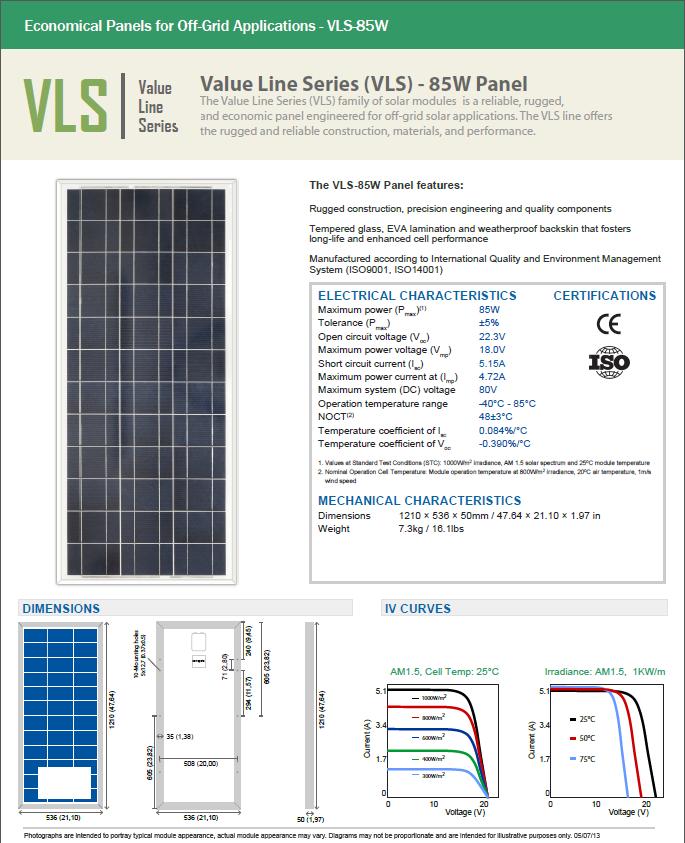
4 2. THEORY OF OPERATION 2.1 System Overview There are three major components in the photovoltaic system: solar modules, batteries, and the system charge controller. Throughout the year, all of the power to the load is provided by the solar array. The photovoltaic array will supply current to charge the battery bank. The controller regulates the battery charging by monitoring the battery terminal voltage and limits the charging current to the battery bank as required. The controller will charge the battery until the voltage reaches 14.1 VDC, then taper the current to maintain a float voltage of 13.7 VDC. The controller also contains a temperature probe and adjusts the charge voltage at a rate of VDC/ C from 25 C. This temperature compensation feature assures the battery is properly charged in cold temperatures and not overcharged in warm temperatures. (Refer to the controller manual in the Appendix for additional details on charge regulation.) Additionally, the controller contains a Low Voltage Disconnect (LVD). This feature will prevent the battery from being over-discharged to a level that could damage and shorten its life. This feature will disconnect the load if battery voltage falls to a voltage of 11.5 VDC. When the battery has been charged to a voltage of 12.6 VDC, the controller will reconnect the battery to the load. 2.1 Component Descriptions Solar Module: A VLS-85W photovoltaic module is used in this system. The module is rated 85W, 18.0VDC under standard test conditions (STC). Additional information on the VLS photovoltaic module can be found in the Appendix. Battery (provided by others): The MK (Deka/East Penn) 8G27 gelled electrolyte battery is recommended for use in this system. The Valve Regulated Lead Acid (VRLA) battery is specifically designed for deep cycle photovoltaic systems. The 12VDC nominal battery has a capacity of 99AH at the 100 hour rate to 1.75VPC. Two batteries may be installed for up to 198AH of energy storage at 12VDC. Controllers: The MorningStar SunSaver charge regulator is used in these solar power systems. The regulator is rated for 10A of charge current and 10A of discharge current at a nominal 12 VDC. Refer to the manual in the Appendix for additional information on the regulator s ratings and operation.
, install the batteries, and make the final wire terminations. 3.")
5 3 SYSTEM INSTALLATION Perform the installation of the system in the order of and as described in the following subsections. 3.1 Overview The SK Systems come pre-assembled and tested. All that is required is to mount the modules and enclosure on a 1.5 SCH 40 pole (provided by others), install the batteries, and make the final wire terminations. 3.2 Recommended Installation Tools Compass (magnetic or GPS) Multimeter Phillips Head Screwdrivers Straight Blade Screwdrivers Socket Set Combination Wrench Set Wire Cutters Wire Strippers Electrical Tape Cable Ties (for wire dressing) 3.3 Site Location Shading of the photovoltaic modules will significantly reduce their energy output and consequently proper battery charging! Be sure to select an array mounting location that will not be shaded by towers, poles, buildings, vegetation (e.g. trees), or hillside cuts through the day. In order for the solar array to receive the maximum energy from the sun, the array must face TRUE South. It is recommended to use a GPS or a magnetic compass to find TRUE South. If using a magnetic compass, ensure there are not steel objects nearby to affect the reading, also be sure to adjust for magnetic declination. (e.g. for Phoenix, AZ, true south is 11 degrees east of magnetic south). Refer to the map below, Figure 2 and the diagram to the right, Figure 1. Note that in general, locations east of the Mississippi will find True South to the west of magnetic south, and locations west of the Mississippi will find True South to the east of magnetic south. Figure 1 True South is 11 degrees East of Magnetic South for Phoenix, AZ
 modules generate electricity when exposed to light, even when they are not connected in a circuit.")
6 Figure 2 Magnetic Declination Map for the U.S. 3.4 Mechanical Assembly WARNING: Electrical Shocks and Burns Hazard Photovoltaic (PV) modules generate electricity when exposed to light, even when they are not connected in a circuit. Shocks and burns can result from contact with module output wiring. These hazards are increased when multiple modules are interconnected to increase array output current or voltage. Cover module front surfaces completely with an opaque cloth or other opaque material before performing any operation involving module or system electrical connections. Use appropriate safety equipment (insulated tools, insulating gloves, etc.) and procedures.
7 CAUTION: Module Breakage The module glass is tempered and will shatter if exposed to impact. Avoid rough handling and lay the modules on a flat, protected surface during assembly. This will also prevent power output at the electrical terminals. Avoid shorting the terminals whenever sunlight is present on the module front surface Mounting Pole Installation All solar equipment is to be attached to a 1.5 SCH 40 pole (provided by others). Ensure the concrete has had adequate time to cure before placing equipment on the pole. Refer to the Site Layout drawing for details Solar Module Support Structure Assembly Observe the following mounting and assembly guidelines: Refer to the structure assembly instructions included with the structure and the Site Layout drawing (in the Appendix) for assembly details. Protect the glass surface of the modules. It is usually best to place the modules face down on a protected surface (e.g. the packing cardboard that came with the module) when attaching the support rails. Use care when working around the back surface of the module as the material can be easily torn or punctured. If the material is damaged, repair the damage with the use of a 100% silicone sealant. 1. Fasten the pole bracket to the pole using the 1.5 U-bolts. 2. Attach the module rails to the end brackets on the pole bracket using the structure hardware provided. 3. Loosen the bolts attaching the pole bracket to the end brackets and slide the end brackets until the module rails line up with the mounting holes on the solar module. 4. Place the PV module on top of the module rails and secure using the module hardware provided. 5. Align the structure to True South and adjust to the correct tilt angle, tighten all hardware System Enclosure Mounting Attach the system enclosure to the pole below the solar array using the pole clamps provided. The pole clamps slide into the slot on the U-channel. Refer to the Site Layout drawing. 3.5 System Wiring WARNING: Electrical Hazard Photovoltaic modules generate high voltage whenever exposed to sunlight. Voltages can be as high as 22 VDC.
8 CAUTION: Electrical Hazard Ensure all fuses are removed and all circuit breakers are in the OFF position before beginning any wiring Grounding The system enclosure should be grounded using the 12AWG ground conductor routed in the load conduit. One end of this wire is connected inside the enclosure to a backplate mounting stud by a 3/8 ring terminal. Connect the other end of wire to the site ground (provided by others) Array Wiring Route the conduit labeled ARRAY up the pole to the module junction box. Open the module junction box. Knock out one of the 1/2 knockouts. Remove the locknut from the conduit connector. Insert the connector into the junction box and secure with the locknut. Terminate the red wire to the module positive output terminal and the black wire to the module negative output terminal using the fork terminals provided. Refer to the System Wiring Diagram in the Appendix Load Installation and Wiring The load can be mounted on the backplate DIN rail, placed on the backplate shelf, or mounted externally from the system enclosure. For external loads, route the conduit labeled LOAD to the load equipment. Enter the load equipment through a 1/2 knockout, and secure using the conduit connector. Terminate the red wire to the load positive input terminal and the black wire to the load negative input terminal. Refer to the System Wiring Diagram in the Appendix Battery Installation and Wiring (batteries provided by others) WARNING: Electrical Hazard Batteries contain high discharge currents; use insulated tools on and around batteries. WARNING: Chemical Hazard Batteries contain sulfuric acid which can cause burns and other serious injury. In the event of contact with sulfuric acid, flush immediately and thoroughly with water. The use of safety goggles, rubber apron, and rubber gloves is recommended. WARNING: Explosive Hazard Batteries can generate explosive gases, which when released, can explode and cause blindness and other serious injury. Keep sparks, flames, and smoking materials away from the battery area.
9 One or two batteries may be used with this system. Remove the top cover foam from the enclosure. Place the first battery in the bottom of the enclosure with the terminals toward the enclosure side (as shown in the Enclosure Layout drawing in the Appendix). Connect the red wire with the red boot cover to the battery positive terminal and the black wire with the black boot cover to the battery negative terminal. If two batteries are used, place the second battery in the bottom of the enclosure with the terminals toward the enclosure side. Install the battery parallel interconnect cables from the first battery to the second battery. When done, place the top cover foam on top of the batteries. Refer to the System Wiring Diagram in the Appendix. WARNING: Battery Parallel Cables If only one battery is used, ensure the battery parallel cables are NOT connected to the battery. 3.6 System Checkout and Commissioning At the end of the installation it is important to confirm and verify all mechanical and electrical connections. Perform the following system checkout and complete the System Installation Checklist. 1 Confirm the proper tilt angle and orientation of the solar module; ensure it is facing true south (and adjusted for magnetic declination if a magnetic compass is used). 2 Ensure all mechanical fasteners are tight and secure. 3 At the controller, check the module short circuit current and open circuit voltage. 4 At the controller, check the voltage and polarity of the battery. The voltage should be approximately 12.5 VDC. 5 Switch on the battery circuit breaker. Verify the green "CHARGING" indicator on the regulator is lit. If it is not lit, go back and check the connections. 6 Switch on the load(s) and verify its proper operation. Ensure the load is operating within the energy design of the system. If needed perform a series current draw.
10 System Installation Checklist and Start-Up Table Module facing true south: (Yes/No) Module at correct tilt angle: (Yes/No) All mechanical fasteners tight: (Yes/No) Record the module open circuit voltage (VOC) and short circuit current (ISC) at the controller. Open Circuit Voltage: VDC Short circuit Current: A Record the initial battery voltage at the controller. Battery bank: VDC Controller Operation: Charging LED illuminated: (Yes/No) Load Disconnect LED illuminated: (Yes/No) Load operating properly: (Yes/No) INSTALLATION IS NOW COMPLETE Tested By: Date: Approved By: Date:
11 4 RECOMMENDED MAINTENANCE Although the solar electric power system should require minimal maintenance a few minutes time every 3-6 months can help to maintain the performance of the system and extend its service life. 4.1 Solar Array 1. The solar array should not need to be completely cleaned unless the dirt build-up is particularly bad. Special care should be taken to look for and remove any bird drops or mud as these essentially shade the module and reduce the output current. When cleaning the front surface of the array use a soft non-abrasive cloth or brush and water. Avoid the use of any cleaning products that may leave residue on the module or promote corrosion on the structure and its fasteners. 2. The tilt angle and orientation should be confirmed per the installation instructions in Section Inspect all electrical connections for looseness, corrosion, chafing, etc. 4. Inspect the module back surface for damage or punctures. Seal any punctures that are found with a commercial grade RTV sealant. If significant impact damage is observed, replace the affected solar module. 4.2 Charge Controller 1. Inspect all electrical connections for looseness or corrosion. 2. Check Charge Controller operation per the manual in the Appendix. 4.3 Battery Bank 1. Inspect all electrical connections for looseness or corrosion. 2. Check and record battery voltages. 4.4 System Wiring 1. Inspect all wiring and connections for tightness, corrosion, insulation integrity, damage, etc. Repair or replace as necessary.
12 5 SYSTEM TROUBLESHOOTING If the system is not functioning correctly, there are a few simple steps to isolate the problem. The solar power system sites must be inspected regularly for damage due to vandalism or wildlife. Loose or damaged wiring can cause severe voltage drop (power loss) or an open circuit of the array, battery or load. In general, basic maintenance should be performed (per Section 4 above) first, as sometimes the potential cause maybe found (e.g. dirty or damaged module, lose wire, etc.) Following are some of the typical factors that contribute to the failure of the system to operate within design parameters: 1. Load greater than system design Installing loads greater than the system was designed for will reduce the performance of the system and damage the batteries. Excessive load operation can either be power, current, or operating time. Daily load energy consumption should be checked to verify it is within the operation parameters of the system. If the load is greater than the system design, the load should be decreased or the system increased (e.g. array, battery, controller, etc.) 2. Shading Even partial shading of the solar module can result in zero output from the module and will result in reduced system performance. Shading can result from improper overgrown vegetation (e.g. trees), cut hillsides, utility poles, towers, buildings; or from excessive dirt or bird droppings. The solar array must be inspected and cleaned at regular intervals (per the maintenance instructions in Section 4); vegetation should be cut or trimmed as necessary. Careful attention should be observed at the time of installation to prevent shading from towers, buildings, poles, etc. and the site moved relocated as necessary to avoid the obstruction. 3. Incorrect orientation or tilt angle Refer to the installation instructions in Section 3 for proper orientation, alignment, and tilt adjustment. Incorrect alignment of the solar array will result in reduced array output and system performance. 4. Poor sunlight conditions Although rare, occasionally unusual weather patterns may occur for an extended period (exceeding the sunless days of battery reserve designed into the system) which will result in reduced system performance and non-operation of the load. Recent weather patterns should be recorded to verify available solar energy. If poor weather conditions prevail the battery capacity or solar array can be increased to increase system performance. 5. System component damage or malfunction If none of the above has corrected the problem; then a failed component is most likely the cause and should be isolated and replaced. a. A damaged solar module will produce less or no power at all (depending on the severity of the damage). Examine the solar module for visible damage. If no damage is found, open the junction box and disconnect the output wires. Using a multimeter, check the short circuit current and open circuit voltage on a clear
13 sunny day. These values should approximate those on the module specification sheet. b. The charge controller may experience malfunction due to excessive currents or a lightning strike. Refer to the controller manual in the Appendix for details on troubleshooting. c. Battery failure may be caused by several factors: age, controller failure, or excessive load operation. If the battery is more than 5 years old is probably nearing the end of its service life and may need to be replaced. A capacity test can confirm the ability of the battery to support the load. If the battery is relatively new (1 to 2 years old) the system should be checked for proper operation. The controller should be tested per the instructions in the controller manual (Appendix). Excessive load operation may result in permanent battery damage (excessive deep discharge). The load should be monitored to confirm it is operation within the design parameters of the system design. 6. If any of the above fails to correct the problem or if new components are required contact technical support (refer to Section 1.3) for additional assistance, please have available the system model number and a brief description of the problem.
14 GLOSSARY OF TERMS Air Mass: Equal to the cosine of the zenith angle - that angle from directly overhead to a line intersecting the sun. The air mass is an indication of the length of the path solar radiation travels through the atmosphere. An air mass of 1.0 means the sun is directly overhead and the radiation travels through one atmosphere (thickness). Alternating Current (ac): An electric current that reverses direction periodically. Ambient Temperature: The temperature of the surrounding area. Ampere (A): Unit of electric current. The rate of flow of electrons in a conductor equal to one coulomb per second. Ampere-Hour (Ah): The quantity of electrical energy equal to the flow of current of one ampere for one hour. The term is used to quantify the energy stored in a battery. Angle of Incidence: The angle that a light ray striking a surface makes with a line perpendicular to the surface. Anode: The positive electrode in an electrochemical cell (battery). Also, the earth ground in a cathodic protection system. Also, the positive terminal of a diode. Array: A collection of electrically connected photovoltaic (PV) modules. Array Current: The electrical current produced by a PV array when it is exposed to sunlight. Array Operating Voltage: The voltage produced by a PV array when exposed to sunlight and connected to a load. Availability: The quality or condition of a PV system being available to provide power to a load. Usually measured in hours per year. One minus availability equals downtime. Azimuth: Horizontal angle measured clockwise from true north; 180 is true south. Battery: A device that converts the chemical energy contained in its active materials directly into electrical energy by means of an electrochemical oxidation-reduction (redox) reaction. Battery Capacity: The total number of ampere-hours that can be withdrawn from a fully charged battery at a specified discharge rate and temperature. See Ampere-Hour. Battery Cell: The smallest unit or section of a battery that can store electrical energy and is capable of furnishing a current to an external load. Battery Cycle Life: The number of times a battery can be discharged and recharged before failing. Battery manufacturers specify Cycle Life as a function of discharge rate and temperature. Battery Self-Discharge: Loss of energy by a battery that is not under load.
15 Battery State of Charge (SOC): Percentage of full charge or 100 percent minus the depth of discharge. See Depth of Discharge. Bypass Diode: A diode connected in parallel with a PV module to provide an alternate current path in case of module shading or failure. Cathode: The negative electrode in an electrochemical cell. Also, the negative terminal of a diode. Charge: The process of adding electrical energy to a battery. Charge Controller: A device that controls the charging rate and/or state of charge for batteries. Charge Controller Terminology: High Voltage Disconnect (HVD): The voltage at which the charge controller will disconnect the array from the batteries to prevent overcharging. Low Voltage Disconnect (LVD): The voltage at which the charge controller will disconnect the load from the batteries to prevent over-discharging. Low Voltage Alarm (LVA): A warning alarm (contact closer) or light (or LED) that indicates that the battery is at a low state of charge (SOC). Maximum Power Tracking or Peak Power Tracking: Operating the array at the peak power point of the array's I-V curve where maximum power is obtained. Pulse Width Modulation (PWM) Controller: High frequency (100 to 1000Hz) solid state series controller which uses PWM to taper the charge current to the battery. Reverse Current Protection: Any method of preventing unwanted current flow from the battery to the PV array (usually at night). Series Controller: A controller that interrupts the charging current by open circuiting the PV array. The control element is in series with the PV array and battery. Shunt Controller: A controller that redirects or shunts the charging current away from the battery. The controller requires a large heat sink to dissipate the current from the short-circuited PV array. Most shunt controllers are for smaller systems producing 30 amperes or less. Temperature Compensation: A circuit that adjusts the charge controller activation points depending on battery temperature. This feature is recommended if the battery temperature is expected to vary more than +/-5 C from ambient temperature. The temperature coefficient for lead acid batteries is typically -3 to -5 millivolts/ C per cell. Charge Factor: A number representing the time in hours during which a battery can be charged at a constant current without damage to the battery. Usually expressed in relation to the total battery capacity, i.e., C/5 indicates a charge factor of 5 hours. Related to Charge Rate. Charge Rate: The current used to recharge a battery. Normally expressed as a percentage of total battery capacity. For instance, C/5 indicates a charging current equal to one-fifth of the battery's capacity.
16 Cloud Enhancement: The increase in solar intensity caused by reflected irradiance from nearby clouds. Current (Amperes, Amps, A): The flow of electric charge in a conductor between two points having a difference in potential (voltage). Cutoff Voltage: The voltage levels (activation) at which the charge controller disconnects the array from the battery or the load from the battery. Cycle: The discharge and subsequent charge of a battery. Days of Storage: The number of consecutive days the stand-alone system will meet a defined load without solar energy input. This term is related to system availability. DC/DC Converter: A unit that converts a dc voltage to another dc voltage. Deep Cycle: Type of battery that can be discharged to a large fraction of capacity many times without damaging the battery. Design Month: The month having the combination of insolation and load that requires the maximum energy from the array. Depth of Discharge (DOD): The percent of the rated battery capacity that has been withdrawn. See Battery State of Discharge. Direct Current (dc): Electric current flowing in only one direction. Discharge: The withdrawal of electrical energy from a battery. Discharge Factor: A number equivalent to the time in hours during which a battery is discharged at constant current usually expressed as a percentage of the total battery capacity, i.e., C/5 indicates a discharge factor of 5 hours. Related to Discharge Rate. Discharge Rate: The current that is withdrawn from a battery over time. Expressed as a percentage of battery capacity. For instance, a C/5 discharge rate indicates a current equal to one-fifth of the rated capacity of the battery. Disconnect: Switch gear used to connect or disconnect components in a PV system. Duty Cycle: The ratio of active time to total time. Used to describe the operating regime of appliances or loads in PV systems. Efficiency: The ratio of output power (or energy) to input power (or energy). Expressed in percent. Equalization Charge: The process of mixing the electrolyte in batteries by periodically overcharging the batteries for a short time. Fixed Tilt Array: A PV array set in at a fixed angle with respect to horizontal.
17 Float Charge: A charge current to a battery that is equal to or slightly greater than the selfdischarge rate. Frequency: The number of repetitions per unit time of a complete waveform, expressed in Hertz (Hz). Insolation: The solar radiation incident on an area over time. Equivalent to energy and usually expressed in kilowatt-hours per square meter. Inverter: An inverter converts dc power from the PV array/battery to ac power compatible with the utility and ac loads. Irradiance: The solar power incident on a surface. Usually expressed. in kilowatts per square meter. Irradiance multiplied by time equals insolation. Kilowatt (kw): One thousand watts. A unit of power. Kilowatt Hour (kwh): One thousand watt-hours. A unit of energy. Power multiplied by time equals energy. Life: The period during which a system is capable of operating above a specified performance level. Load: The amount of electric power used by any electrical unit or appliance at any given time. Load Current (A): The current required by the electrical device. Module: The smallest replaceable unit in a PV array. An integral, encapsulated unit containing a number of PV cells. Normal Operating Cell Temperature (NOCT): The estimated temperature of a PV module when operating under 800 w/m2 irradiance, 20 C ambient temperature and wind speed of 1 meter per second. NOCT is used to estimate the nominal operating temperature of a module in its working environment. Nominal Voltage: A reference voltage used to describe batteries, modules, or systems (i.e., a 12- volt or 24-volt battery, module, or system). Open Circuit Voltage: The maximum voltage produced by an illuminated photovoltaic cell, module, or array with no load connected. This value will increase as the temperature of the PV material decreases. Operating Point: The current and voltage that a module or array produces when connected to a load. The operating point is dependent on the load or the batteries connected to the output terminals of the array. Orientation: Placement with respect to the cardinal directions, N, S, E, W; azimuth is the measure of orientation from north. Overcharge: Forcing current into a fully charged battery. The battery will be damaged if
18 overcharged for a long period. Panel: A designation for a number of PV modules assembled in a single mechanical frame. Parallel Connection: Term used to describe the interconnecting of PV modules or batteries in which like terminals are connected together. Increases the current at the same voltage. Peak Load: The maximum load demand on a system. Peak Sun Hours: The equivalent number of hours per day when solar irradiance averages 1,000 w/m2. For example, six peak sun hours means that the energy received during total daylight hours equals the energy that would have been received had the irradiance for six hours been 1,000 w/m2. Photovoltaic System: An installation of PV modules and other components designed to produce power from sunlight and meet the power demand for a designated load. Power (Watts): A basic unit of electricity equal (in dc circuits) to the product of current and voltage. Remote Site: A site not serviced by an electrical utility grid. Series Connection: Connecting the positive of one module to the negative of the next module. This connection of PV modules or batteries increases the voltage while the current remains the same. Short Circuit Current (Isc): The current produced by an illuminated PV cell, module, or array when its output terminals are shorted. Stand-Alone PV System: A photovoltaic system that operates independent of the utility grid. State of Charge (SOC): The instantaneous capacity of a battery expressed at a percentage of rated capacity. String: A number of modules or panels interconnected electrically in series to produce the operating voltage required by the load. System Availability: The percentage of time (usually expressed in hours per year) when a PV system will be able to fully meet the load demand. Tilt Angle: The angle of inclination of a solar collector measured from the horizontal. Volt (V): The unit of electromotive force that will force a current of one ampere through a resistance of one ohm. Watt (W): The unit of electrical power. The power developed when a current of one ampere flows through a potential difference of one volt; 1/746 of a horsepower. Watt Hour (Wh): A unit of energy equal to one watt of power connected for one hour.
19 Drawing 1: Wiring Diagram
20 Drawing 2: Site Layout
21 Drawing 3: Enclosure Layout
22 Drawing 4: SPM1-Multi-V3-Landscape
23 Drawing 5: SPM1-Multi-V3-Portrait
24 Solar Panel Specifications
25 Morningstar Charge Controller Information

26
27
28
29
30

31

32

33

34
35
36


 100% solid state.")
 for cool operation 4-stage charging: bulk, absorption, float,")


37 SUNSAVER TM Solar Controller Morningstar is pleased to introduce our third generation SunSaver. Since its first market introduction in 1996, over 1 million SunSaver controllers have been installed in over 73 countries for numerous solar power systems including oil/gas, telecom and instrumentation, marine and boating, and remote homes. We have retained much of our legacy design including the same ratings, footprint and simple user interface, and have added several new and advanced high value features: Full electronic protections 4 stage battery charging Self-diagnostics to detect critical faults Multi-color status LED 3 LED s for battery state of charge Dead battery recovery Telecom mode for sensitive loads Maximum charge limiting for sensitive loads Cover to protect wire terminals Additional certifications Key Features and Benefits Extremely High Reliability Failure rate of less than 1 per 1,000 shipped (<0.1%) 100% solid state. Power MOSFET design Manufactured in an ISO 9000 factory 100% pre-shipment functional testing Longer Battery Life Advanced PWM charging Series design (not shunt) for cool operation 4-stage charging: bulk, absorption, float, equalize Optimized sealed or flooded battery set points Temperature compensated charging Low voltage load disconnect on several versions Designed for Harsh Environments Temperature rating of 40 C to +60 C Epoxy encapsulation for protection against humidity and dust ingress Corrosion protection: marine rated terminals and anodized aluminum case Certified for use in hazardous locations Easy to Install and Use Factory pre-sets result in no required install settings Electronic protections prevent damage from wiring mistakes Fully automatic operation and fault recovery LED s display about status, faults and battery condition
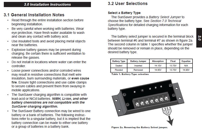
38 SUNSAVER TM S o l a r c o n t r o l l e r SunSaver Versions SS-6-12V SS-6L-12V SS-10-12V SS-10L-12V SS-10L-24V SS-20L-12V SS-20L-24V Solar Load System Current Current Voltage LVD 6A 6A 12V No 6A 6A 12V Yes 10A 10A 12V No 10A 10A 12V Yes 10A 10A 24V Yes 20A 20A 12V Yes 20A 20A 24V Yes + - SunSaver shown with wire terminal cover. T ECH N I C A L S P E C I F I C A T I O N S Electrical Max. PV and load ratings System voltage Min. battery voltage Regulation voltage Per above 12 or 24 volts 1 volt 12 volt 24 volt Sealed battery 14.1 V 28.2 V Flooded battery 14.4 V 28.8 V Load disconnect LVD reconnect Max. solar voltage 12V battery 24V battery Load in-rush capability SunSaver-6 SunSaver-10 SunSaver-20 Self-consumption Voltage accuracy Transient surge protection Mechanical Wire size Environmental Ambient temperature Storage temperature Humidity Tropicalization 11.5 V 23.0 V 12.6 V 25.2 V 30 volts 60 volts 45 amps 65 amps 140 amps < 8 ma 12V: +/ 25 mv (typical) 24V: +/ 48 mv (typical) 1500W per connection Electronic Protections Solar: Overload, short-circuit, high voltage Load: Overload, short-circuit, high voltage Battery: High voltage All: Reverse polarity, high temperature, lightning and transient surges Reverse current at night Battery Charging Charging method Charging stages Temperature compensation Coefficient Range Set points LED Indications Status LED (1) Battery LED s (3) Certifications 4 stage series PWM Bulk, absorption, float, equalize 12V: 30mV/ C 24V: 60mV/ C 30 C to +60 C Absorption, float, equalize Charging or not charging Solar error conditions Battery level Charging stage 5 mm 2 / #10 AWG Weight (unpacked) 0.23kg / 8 oz. ETL Listed to UL 1741 and CSA C22.2 No Dimensions 15.2 x 5.5 x 3.4 cm Hazardous Locations 6.0 x 2.2 x 1.3 inch 40 C to +60 C 55 C to +80 C 100% non-condensing Epoxy encapsulation Marine rated terminals Anodized aluminum case EMC Directives FCC CE RoHS ISO 9000 Class 1, Division 2, Groups A,B,C,D CSA C22.2#213 Immunity, emissions, safety Class B Part 15 8 Pheasant Run Newtown PA USA Tel: Fax: info@morningstarcorp.com Website:
39
PHOTOVOLTAIC SYSTEM CONTROLLERS SUNSAVER MODELS INCLUDED IN THIS MANUAL SS-6 / SS-6L SS-10 / SS-10L SS-10-24V / SS-10L-24V SS-20L SS-20L-24V
 PHOTOVOLTAIC SYSTEM CONTROLLERS OPERATOR S MANUAL SUNSAVER MODELS INCLUDED IN THIS MANUAL SS-6 / SS-6L SS-10 / SS-10L SS-10-24V / SS-10L-24V SS-20L SS-20L-24V 6A / 12V 10A / 12V 10A / 24V 20A / 12V 20A
SOLAR LIGHTING CONTROLLER SUNLIGHT MODELS INCLUDED IN THIS MANUAL SL-10 SL-10-24V SL-20 SL-20-24V
 SOLAR LIGHTING CONTROLLER OPERATOR S MANUAL SUNLIGHT MODELS INCLUDED IN THIS MANUAL SL-10 SL-10-24V SL-20 SL-20-24V 10A / 12V 10A / 24V 20A / 12V 20A / 24V 1098 Washington Crossing Road Washington Crossing,
SMT. Installation and Operation Manual. Model:SMT WITH MPPT TECHNOLOGY
 SMT WITH MPPT TECHNOLOGY Installation and Operation Manual Model:SMT SMT Dimensions Specification Summary System Voltage 12 V/24V Rated Battery Current 12V, 5A 8A 10A 15A 20A 25A 24V, 5A 8A 10A 15A Rated
The Traveler Series: Adventurer
 The Traveler Series: Adventurer RENOGY 30A Flush Mount Charge Controller Manual 2775 E. Philadelphia St., Ontario, CA 91761 1-800-330-8678 Version: 2.2 Important Safety Instructions Please save these instructions.
The Traveler Series TM : Adventurer
 The Traveler Series TM : Adventurer 30A PWM Flush Mount Charge Controller w/ LCD Display 2775 E. Philadelphia St., Ontario, CA 91761 1-800-330-8678 Version: 3.4 Important Safety Instructions Please save
Owner s Manual. Contents GP-PWM-10-SQ
 Owner s Manual Contents 1.0 Installation Overview... 2 2.0 Warnings... 2 3.0 Choosing a Location... 3 4.0 Installation Instructions... 3 5.0 Operating Instructions... 4 6.0 Frequently Asked Questions (FAQs)...
Eclipse Solar Suitcase
 Eclipse Solar Suitcase Renogy 100W 200W 2775 E. Philadelphia St., Ontario, CA 91761 1-800-330-8678 Version 1.0 Important Safety Instructions Please save these instructions. This manual contains important
Solar Electric Modules
 SOLAR ELECTRIC MODULES The balance of this catalog lists and describes all of the equipment that you might need for a renewable energy system. We start with solar modules since they are your power producers
Owner s Manual. Solar Controller GP-PWM-30
 Owner s Manual Solar Controller GP-PWM-30 1.0 Installation Overview 1.1 Introduction A Solar Controller (or Charge Controller / Regulator) is an essential component of your photovoltaic solar system. The
Owner s Manual. Contents GP-PWM-30-SQ GP-PWM-30-SQ
 Owner s Manual Contents 1.0 Installation Overview... 2 2.0 Warnings... 2 3.0 Choosing a Location...3 4.0 Installation Instructions... 3 5.0 Operating Instructions...4 6.0 Frequently Asked Questions (FAQs)...6
LS0512 Solar Charge Controller
 LandStar LS0512 Solar Charge Controller Nominal system voltage Maximum PV input voltage Nominal charge / discharge current 12VDC 35V 5A Contents 1 Important Safety Information... 1 2 General Information...
The Traveler Series: Wanderer
 The Traveler Series: Wanderer RENOGY 30A Charge Controller Manual 2775 E. Philadelphia St., Ontario, CA 91761 1-800-330-8678 Version: 2.0 Important Safety Instructions Please save these instructions. This
User Manual. Solar Charge Controller 3KW
 User Manual Solar Charge Controller 3KW 1 CONTENTS 1 ABOUT THIS MANUAL... 3 1.1 Purpose... 3 1.2 Scope... 3 1.3 SAFETY INSTRUCTIONS... 3 2 INTRODUCTION... 4 2.1 Features... 4 2.2 Product Overview... 5
The Traveler Series: Wanderer
 The Traveler Series: Wanderer RENOGY 30A PWM Charge Controller Manual 2775 E. Philadelphia St., Ontario, CA 91761 1-800-330-8678 1 Version: 2.3 Important Safety Instructions Please save these instructions.
Title Goes Here and Can Run Solar Photovoltaic up to 3 lines as shown here Systems as you see
 Title Goes Here and Can Run Solar Photovoltaic up to 3 lines as shown here Systems as you see CHAPTER 2 Outline the components of a solar photovoltaic system Describe the operation of a solar photovoltaic
LS0512R Solar Light Controller
 LandStar LS0512R Solar Light Controller Nominal system voltage Maximum PV input voltage Nominal charge / discharge current 12VDC 35V 5A Contents 1 Important Safety Information... 1 2 General Information...
Installation, Operation and Maintenance Guide. 12, 24, and 48 Volt Systems
 Solar Power Systems Installation, Operation and Maintenance Guide 12, 24, and 48 Volt Systems Document Number: 06809 Rev A Document #: 06809 Ventev Innovations (A Division of TESSCO Technologies) 10999
Product Manual. Installation Instructions for CHSM-230M Series Solar Module
 Product Manual Installation Instructions for CHSM-230M Series Solar Module CHSM-230M series solar module is made of 60 pieces of 156 mm 156 mm crystalline solar cells in series with high efficiency, high
Installation and Operating Instructions. Solar System Controller ISC3020
 Installation and Operating Instructions Solar System Controller ISC3020 ABOUT THIS MANUAL These operating instructions come with the product and should be kept with it as a reference to all user s of
Glossary. * Credit for glossary starter: Florida Solar Energy Center. August 2015 PV Installer's Course: Glossary 1
 ALTERNATING CURRENT (AC): Electric current (flow of electrons) in which the direction of flow is reversed at constant intervals, such as 60 cycles per second. AMORPHOUS SILICON: silicon with no crystal
10A / 15A / 20A Solar Charge Controller. PU1024 / PU1524 / PU2024 series INSTRUCTION MANUAL
 10A / 15A / 20A Solar Charge Controller PU1024 / PU1524 / PU2024 series INSTRUCTION MANUAL Dear Customer, Thank you very much for choosing our product. This manual contains important information about
KIT-STCS60D KIT-STCS100D Solar Suitcase 60W and 100W Owner s Manual
 KIT-STCS60D KIT-STCS100D Solar Suitcase 60W and 100W Owner s Manual RNG Group Inc. (Renogy) 14288 Central Ave., Suite A Chino, CA 91710 1-800-330-8678 Product Description The Renogy Solar Suitcases combine
User Manual Solar Charge Controller 3KW
 User Manual Solar Charge Controller 3KW Version: 1.3 CONTENTS 1 ABOUT THIS MANUAL... 1 1.1 Purpose... 1 1.2 Scope... 1 1.3 SAFETY INSTRUCTIONS... 1 2 INTRODUCTION... 2 2.1 Features... 2 2.2 Product Overview...
Reference: Photovoltaic Systems, p References: Photovoltaic Systems, Chap. 7 National Electrical Code (NEC), Articles 110,
, Articles 110,") Charge controllers are required in most PV systems using a battery to protect against battery overcharging and overdischarging. There are different types of charge controller design, and their specifications
Charge controllers are required in most PV systems using a battery to protect against battery overcharging and overdischarging. There are different types of charge controller design, and their specifications
GV-4 Manual 4A / 50W IMPORTANT SAFETY INSTRUCTIONS SAVE THESE INSTRUCTIONS. Solar Charge Controller with Maximum Power Point Tracking.
 GV-4 Manual Solar Charge Controller with Maximum Power Point Tracking For models: GV-4-Pb-12V: 12V Lead-Acid/AGM/Gel/Sealed/Flooded http://genasun.com Genasun Inc. 1035 Cambridge st. Suite 16B Cambridge,
Photovoltaic Module User Manual
 Photovoltaic Module User Manual Index of Contents: Overview... 1 Applicable Products... 1 Unpacking... 2 Preparation before Installation... 3 Installation and operation... 3 Wiring and Connection... 5
Portable Solar Panels MSK-90 MSK-135. Manual. Please read this manual before using your MSK-90 or MSK-135.
 Portable Solar Panels MSK-90 MSK-135 Owner's Manual Please read this manual before using your MSK-90 or MSK-135. Section 1 Safety Instructions IMPORTANT SAFETY INSTRUCTIONS PLEASE READ THE FOLLOWING SAFETY
Rover Series. Rover 20A 40A Maximum Power Point Tracking Solar Charge Controller
 Rover Series Rover 20A 40A Maximum Power Point Tracking Solar Charge Controller 0 2775 E. Philadelphia St., Ontario, CA 91761 1-800-330-8678 Version 1.5 Important Safety Instructions Please save these
Chapter 6. Batteries. Types and Characteristics Functions and Features Specifications and Ratings Jim Dunlop Solar
 Chapter 6 Batteries Types and Characteristics Functions and Features Specifications and Ratings 2012 Jim Dunlop Solar Overview Describing why batteries are used in PV systems. Identifying the basic components
Safety and Installation Instructions
 Safety and Installation Instructions This document applies to the following UL-listed Gloria Solar Standard Modules: GSM6- series GSS6- series Rev: 1.2 Release Date: September 03, 2009 Gloria Solar Co.,
DURA-PANEL W OUTPUT: 12 VDC, 20 Watt W OUTPUT: 12 VDC, 50 Watt W OUTPUT: 12 VDC, 100 Watt
 INSTRUCTION MANUAL DURA-PANEL RIGID SOLAR PANEL CHARGING SYSTEM 20W, 50W & 100W SOLAR PANELS SERIES 091-246-20W OUTPUT: 12 VDC, 20 Watt 091-246-50W OUTPUT: 12 VDC, 50 Watt Charge Controller 091-246-100W
User s Manual. Automatic Switch-Mode Battery Charger
 User s Manual Automatic Switch-Mode Battery Charger IMPORTANT Read, understand, and follow these safety rules and operating instructions before using this battery charger. Only authorized and trained service
Installation and Operation Manual. Dual Battery Charging Solar Controller. for RVs, Caravans, and Boats. Ratings. Rated Solar Current 25 Amps
 SUNSAVER DUO TM Installation and Operation Manual. Dual Battery Charging Solar Controller for RVs, Caravans, and Boats.. Ratings Nominal Voltage 12 Volts Rated Solar Current 25 Amps 1098 Washington Crossing
SunWize SW and OEM Series Solar Modules GENERAL INSTALLATION & USER GUIDE
 SunWize SW and OEM Series Solar Modules GENERAL INSTALLATION & USER GUIDE Introduction This guide contains application and user safety information you should become familiar with before using your SW/OEM
Photovoltaic Module with Battery Back-up Installation & Maintenance Information IF Figure 1. SAVE THESE INSTRUCTIONS FOR FUTURE REFERENCE
 Photovoltaic Module with Battery Back-up Installation & Maintenance Information IF 1589 SAVE THESE INSTRUCTIONS FOR FUTURE REFERENCE To prevent injury, death, or damage to your photovoltaic system, be
SBC / 2140 / Stage Battery Charger User Manual
 SBC - 2130 / 2140 / 2150 3 Stage Battery Charger User Manual Keep this manual in a safe place for quick reference at all times. This manual contains important safety and operation instructions for correct
General Installation Manual 2007 Sanyo Electric Co., Ltd. All Rights Reserved 6/15/07
 General Installation Manual for SANYO HIT Photovoltaic Modules. Please read this manual completely before use or installation of SANYO modules. This manual applies to the following models: HIP-205BA3,
HydroLynx Systems, Inc. Model 5033-XX Solar Panel. Instruction Manual
 HydroLynx Systems, Inc. Model 5033-XX Solar Panel Instruction Manual Document No: A102759 Document Revision Date: December, 2004 HydroLynx Systems, Inc. Model 5033-XX Solar Panel Receiving and Unpacking
Installation and Operating Instructions. MPPT Solar System Controller ISC3040
 Installation and Operating Instructions MPPT Solar System Controller ISC3040 ABOUT THIS MANUAL These operating instructions come with the product and should be kept with it as a reference to all user s
Phocos CML-V2. Solar charge controller. User Manual (English) Dear customer,
 Dear customer,") Phocos CML-V2 Solar charge controller User Manual (English) Dear customer, Thank you very much for buying this Phocos product. Please read the instructions carefully and thoroughly before using the product.
Phocos CML-V2 Solar charge controller User Manual (English) Dear customer, Thank you very much for buying this Phocos product. Please read the instructions carefully and thoroughly before using the product.
Duo Battery Charge Controller
 Duo Battery Charge Controller RENOGY 10A 20A Pulse Width Modulation Solar Charge Controller Manual 1 2775 E. Philadelphia St., Ontario CA 91761 1-800-330-8678 Version: 1.2 Important Safety Instructions
SPECIAL SPECIFICATION 6576 Solar Panel Power Supply System
 2004 Specifications CSJ 1068-04-126, 0197-02-108 SPECIAL SPECIFICATION 6576 Solar Panel Power Supply System 1. Description. This work shall consist of furnishing and installing an integrated solar Panel
Installation and Operating Instructions. Solar System Controller ISC3030
 Installation and Operating Instructions Solar System Controller ISC3030 ABOUT THIS MANUAL These operating instructions come with the product and should be kept with it as a reference to all user s of the
PV System Components. EE 495/695 Spring 2011
 PV System Components EE 495/695 Spring 2011 Main Components of Grid-Connected PV systems Battery storage is added to some grid-tied PV systems. Example of a grid-tied PV systems Main Components of Stand-Alone
Solar Controller GP-PWM-30. Owner s Manual Go Power! By Valterra Power
 Solar Controller GP-PWM-30 Owner s Manual 1 2 CONTENTS 1.0 Installation Overview 4 1.1 Introduction 4 1.2 Specifications 5 2.0 Warnings 6 3.0 Tools and Materials Needed 7 4.0 Choosing a Location 7 5.0
2006/2007 Product Catalog. The World s Leading SOLAR Controllers
 2006/2007 Product Catalog The World s Leading SOLAR Controllers OUR COMPANY Morningstar Corporation, founded in 1993, is the world s leading supplier of photovoltaic (PV) controllers. In 2005 we shipped
Installation and operating instructions. Solar charge controller MPPT 10 A / 20 A Z Z
 Installation and operating instructions Solar charge controller MPPT 10 A / 20 A EN 1 Contents 1. About these instructions... 3 1.1 Applicability... 3 1.2 Users... 3 1.3 Description of symbols... 3 2.
12/24 VOLT AUTOMATIC SOLAR CHARGE CONTROLLER
 12/24 VOLT AUTOMATIC SOLAR CHARGE CONTROLLER P/No.s SC320 & SC330 WARNING Please read these instructions completely prior to installation. Lead acid batteries can be dangerous. Ensure no sparks or flames
Sunwize Power Ready Express Quick Start
 Document # 310002 Sunwize Power Ready Express Quick Start The purpose of this guide is to assist you in setting up your system quickly and efficiently. Important! Prior to field installation Determine
FUM-24xxCBP Series 3 Stage Battery Charger User Manual
 FUM-24xxCBP Series 3 Stage Battery Charger User Manual Keep this manual in a safe place for quick reference at all times. This manual contains important safety and operation instructions for correct use
Installation Manual. Opal Solar QSA Series
 Installation Manual Opal Solar QSA Series Contents 1.Safety... 1 2.Disclaimer of Liability... 1 3.Transporting, Unpacking and Storing... 1 4. Mechanical Installation... 2 4.1 Site Specification... 2 4.2
SCC-MPPT Solar Charge Controller
 Table 4: Alarm point for low battery voltage table Model Alarm point SCC-MPPT-300 10.5 V SCC-MPPT-600 21.0 V Table 5: Charging hour table for reference Battery Capacity To 90% capacity @ 25A charging current
Designing Stand Alone Systems. Overview, components and function, Elements in Design
 Designing Stand Alone Systems Overview, components and function, Elements in Design What Stand Alone System Does Loads that are Reasonable for a Stand Alone System to Power: Yes or No Dishwasher? Refrigerator
GV-10 Manual 10.5A / 140W IMPORTANT SAFETY INSTRUCTIONS SAVE THESE INSTRUCTIONS. Solar Charge Controllers with Maximum Power Point Tracking
 GV-10 Manual Solar Charge Controllers with Maximum Power Point Tracking For models: GV-10-Pb-12V: GV-10-Pb-CV: 12V Lead-Acid/AGM/Gel/Sealed/Flooded 12V Custom Multi-Stage Lead-Acid/AGM/Gel/ Sealed/Flooded
Solar Controller GP-PWM-30. Owner s Manual
 Owner s Manual 1 2 CONTENTS 1.0 Installation Overview 4 1.1 Introduction 4 1.2 Specifications 5 2.0 Warnings 6 3.0 Tools and Materials Needed 7 4.0 Choosing a Location 7 5.0 Installation Instructions 8
PV Charge Controller SBC-7108 / 7112 / 7120
 PV Charge Controller SBC-7108 / 7112 / 7120 User's Manual NOTE: Please note that features like LCD read out of AH logging of 3 days (see Section 3.3) and 10 Night-light mode (see Section 4.3) are available
INSTALLATION INSTRUCTIONS
 INSTALLATION INSTRUCTIONS WARNING: WARNING: www.altronicinc.com DEVIATION DEVIATION FROM THESE FROM INSTRUCTIONS THESE INSTRUCTIONS MAY LEAD MAY TO LEAD IMPROPER TO IMPROPER OP- ERATION OF ENGINE THE MACHINE
Copyright 2012 DelSolar Co. Ltd MQWRD installation manual-iec Ver. 1.4
 INSTALLATION MANUAL IEC Version www.delsolarpv.com Copyright 2012 DelSolar Co. Ltd MQWRD-01-14--installation manual-iec Ver. 1.4 Content General information 1 Safety precaution for installing solar PV
SCC-MPPT Solar Charge Controller
 Table 3: Charging voltage for 4 types of battery Battery Battery 12V battery system 24V battery system Type Type Code Bulk Floating Bulk Floating Vented 01 14.3 V 13.2 V 28.6 V 26.4 V Sealed 02 14.3 V
SK-10. Features. Solar Charge Controller User Manual. Important Safety Information
 SK-10 Solar Charge Controller User Manual 12V/24V 10Amp Dear Users: Thank you for selecting our product. Please read this manual carefully before you use this product. This product is of cutting edge design,
Solar Charge Controller
 Table 3: Charging voltage for 4 types of battery Battery Type Battery Type Code SC-600W MPPT Bulk Voltage Floating Voltage Vented 01 28.6 V 26.4 V Sealed 02 28.6 V 26.8 V Gel 03 28.6 V 27.4 V NiCd 04 28.6
SunWize SWPB Series Solar Modules GENERAL INSTALLATION & USER GUIDE
 SunWize SWPB Series Solar Modules GENERAL INSTALLATION & USER GUIDE Introduction This guide contains application and user safety information you should become familiar with before using your SWPB series
SCC-MPPT Solar Charge Controller
 Solar Charge Controller Quick Guide 200W 300W 400W 600W 850W V. 2.2 1. Introduction solar charge controller uses PWM-based DSP controller to keep the batteries regulated and prevent batteries from overcharging
12-Batteries and Inverters. ECEGR 452 Renewable Energy Systems
 12-Batteries and Inverters ECEGR 452 Renewable Energy Systems Overview Batteries Lead-Acid Batteries Battery Specifications Battery Charge Controllers Inverters Dr. Louie 2 Batteries Incorporation of a
OD10 10A Outdoor Solar Charge Controller
 OD10 10A Outdoor Solar Charge Controller CHC-OD12-10 User s Manual Page 1 of 14 windynation Revision 2 Table of Contents 1.1 Features...3 1.2 Safety Information...4 1.3 Specifications...4 1.3.1 Electrical
672W Off Grid Residential Package
 672W Off Grid Residential Package List Price:$9,578.71 Our Price: $8,523.43 Save: $1,055.28 Our Code: KITOFFGRID-A This item is a package made up of the following components. Please call to speak to a
NorthStar Battery Company DCN: SES DCR: 1548-S09 Date:
 Application Manual and Product Information for NorthStar Battery Company Table of Contents Introduction...3 NSB Blue Series Benefits...4 ISO Certifications...5 NSB Blue Product Specifications...6 Leak
WITH TRAKSTAR TM MPPT TECHNOLOGY. Installation and Operation Manual. Model: SS-MPPT-15L
 SUNSAVER MPPT TM WITH TRAKSTAR TM MPPT TECHNOLOGY Installation and Operation Manual MAXIMUM POWER POINT TRACKING Model: SS-MPPT-15L 1098 Washington Crossing Road Washington Crossing, PA 18977 USA www.morningstarcorp.com
Installation Manual. Installation Manual. AXITEC, LLC 160 Greentree Drive, Suite 101 Dover, Delaware
 Installation Manual AXITEC, LLC 160 Greentree Drive, Suite 101 Dover, Delaware 19904 www.axitecsolar.com Release: 151121 1/13 AXITEC_manual_151121 Table of Contents Introduction... 3 Disclaimer of liability...
Installation Manual AXITEC SOLAR MODULES
 Installation Manual AXITEC SOLAR MODULES 1/12 AXITEC INSTALLATION USA 160504 Table of Contents INTRODUCTION... 3 DISCLAIMER OF LIABILITY... 3 GENERAL INFORMATION... 3 SAFETY... 3 1 WARNING AND CAUTION...
Your new LM controller is a state-of-the art device which was developed in accordance with the latest
 CAP LM-series Solar charge controller User Manual Thank you very much for buying this CAP product. Please read the instructions carefully and thoroughly before using the products. Your new LM controller
INSTALLATION MANUAL.
 INSTALLATION MANUAL D6M_BxA Series : D6M_B1A / D6M_B2A / D6M_B3A / D6M_B5A D6M_AxA Series : D6M_A1A / D6M_A2A / D6M_A3A / D6M_A5A D6P_BxA Series : D6P_B1A / D6P_B2A / D6P_B3A / D6P_B5A D6P_AxA Series :
MP V 8A Electronic Smart Charger. Instruction and Information Manual
 MP7428 12V 8A Electronic Smart Charger Instruction and Information Manual In order to ensure correct and safe usage of your battery charger, you should read these instructions carefully. Please retain
SOLAR CHARGE CONTROLLER
 SOLAR CHARGE CONTROLLER SCE 1010 / SCE 1515 / SCE 2020 / SCE 3030 Instruction Manual Please read user manual carefully before use. 1.About this manual These operating instructions are part of the product.
INSTALLATION INSTRUCTION AND MAINTENANCE MANUAL
 INSTALLATION INSTRUCTION AND MAINTENANCE MANUAL FOR CRYSTALLINE SOLAR PV MODULE REVISIONS Risen Energy Co.,Ltd REV ECO/NPA DESCRIPTION OF CHANGE CHK D/DATE APP D/DATE TITLE: A 07-2015 Revised the entire
Nanometrics Solar Power System
 Nanometrics Solar Power System Installation Guide Nanometrics Inc. Kanata, Ontario Canada 2003 Nanometrics Inc. All Rights Reserved. Installation Guide The information in this document has been carefully
PM300P00 Installation Guide for Users
 BenQ Solar Photovoltaic Modules (IEC, UL) PM300P00 Installation Guide for Users Note: The content of this specification is subject to change. 2012 AU Optronics All Rights Reserved, Do Not Copy. BenQ Solar
DIN Rail UPS Model: DIN-UPS Installation/Operation Manual
 DIN Rail UPS Model: DIN-UPS 24-10 Installation/Operation Manual Table of Contents Section Page Section Page Quick Start 2 1) General Information 4 Materials Provided 4 Optional Equipment 4 2) Safety Information
SUNLIGHT SUNLIGHT MODELS INCLUDED IN THIS MANUAL MORNINGSTAR. C 0 r p o r a t i 0 fl
 SUNLIGHT SOLAR LIGHTING CONTROLLER OPERATOR S MANUAL SUNLIGHT MODELS INCLUDED IN THIS MANUAL SL-1O 1OA/12V SL-1O-24V 1OA/24V SL-20 20A/12V SL-20-24V 20A / 24V MORNINGSTAR C 0 r p o r a t i 0 fl 1098 Washington
The Solar Power Kit includes the following components. Please be sure you have all listed components before beginning. 5/16" x 2" Carriage Bolt
 Solar Power Kit For Cabled Weather Stations This manual describes how to install and use the Solar Power Kit. The Solar Power Kit enables cabled stations, cabled Weather Envoys to be stand-alone units,
GVB-8 (Boost) Manual
 Manual") www.genasun.com GVB-8 (Boost) Manual Solar Charge Controllers with Maximum Power Point Tracking For models: GVB-8-Pb-12V: 12V Lead-Acid/AGM/Gel/Sealed/Flooded GVB-8-Pb-24V: 24V Lead-Acid/AGM/Gel/Sealed/Flooded
www.genasun.com GVB-8 (Boost) Manual Solar Charge Controllers with Maximum Power Point Tracking For models: GVB-8-Pb-12V: 12V Lead-Acid/AGM/Gel/Sealed/Flooded GVB-8-Pb-24V: 24V Lead-Acid/AGM/Gel/Sealed/Flooded
MODEL ELC-12/40-CVM-D BATTERY CHARGER
 NATIONAL RAILWAY SUPPLY MODEL ELC-12/40-CVM-D BATTERY CHARGER Installing, Operating and Service Instructions for the ELC-12/40-CVM-D Solid State Charger PLEASE SAVE THESE IMPORTANT SAFETY AND OPERATING
SPECIAL SPECIFICATION 8676 Solar Panel Power Supply System
 2004 Specifications CSJ 2552-01-033 SPECIAL SPECIFICATION 8676 Solar Panel Power Supply System 1. Description. This work shall consist of furnishing and installing an integrated Solar Panel Power Supply
Powerterm L120C Single Output PSU/Battery Chargers Model C2199A-1 (12V/8A) or Model C2199A-2 (24V/6A)
 or Model C2199A-2 (24V/6A)") A Complete solution for small battery-backed dc instrument power systems. DATASHEET Supply 12Vdc 8A or 24Vdc 6A loads Ideal for RTU s, dataloggers, remote field instrumentation, alarm systems, etc. where
A Complete solution for small battery-backed dc instrument power systems. DATASHEET Supply 12Vdc 8A or 24Vdc 6A loads Ideal for RTU s, dataloggers, remote field instrumentation, alarm systems, etc. where
INSTALLATION MANUAL THE / MODULE. IEC & UL version
 INSTALLATION MANUAL IEC & UL version THE / MODULE Duomax Duomax Duomax M Plus TSM-PDG40.40 TSM-PDG40.47 TSM-PDG5.40 TSM-PDG5.47 TSM-PDG14.40 TSM-PDG14.47 TSM-PEG40.40 TSM-PEG40.47 TSM-PEG5.40 TSM-PEG5.47
FHOTON Drive. Installation Guide
 FHOTON Drive Installation Guide 2 SUBDRIVE SOLAR INSTALLATION MANUAL TABLE OF CONTENTS Overview...5 Descriptions and Features...5 How it Works...6 Features...8 Installation...11 Controller Location Selection...
SMPPT. Solar Charge Controller with Maximum Power Point Tracking. Installation & Operation Manual
 SMPPT Solar Charge Controller with Maximum Power Point Tracking 10A/20A/30A 12V/24V Installation & Operation Manual 1 Dear Consumer: Thank you very much for using our product! We will offer you the permanent
Nature Power Inverters. True Sinewave Inverter Modified Sinewave Inverter. Owner s Manual
 Version 1.1 Version 2 Nature Power Inverters True Sinewave Inverter Modified Sinewave Inverter Owner s Manual!!!!!!!!!!! 38304 38204 For safe and optimum performance, the Power Inverter must be used properly.
CP-250E-60/72-208/240-MC4 Microinverter with Modular Trunk Cable
 CP-250E-60/72-208/240-MC4 Microinverter with Modular Trunk Cable Chilicon Power Aug 2016 1 CONTENTS CP-250E Microinverter System... 3 The CP-100 Cortex Gateway... 3 Important Safety Information... 4 Inverter
Technical specifications
 KINGDOM OF SAUDI ARABIA THE SAUDI FUND FOR DEVELOPMENT ( SFD) ITB -207-7 Technical specifications Project name: Reconstruction, Furniture and Equipping of Three Schools Photovoltaic Solar System for Holly
2008/2009 Product Catalog
 2008/2009 Product Catalog in English The World s Leading Solar Controllers & Inverters Our company Morningstar Corporation, founded in 1993, is the world s leading supplier of photovoltaic (PV) controllers.
General Installation Manual Mar 2009, Sanyo Electric Co., Ltd. All Rights Reserved 3/23/09
 General Installation Manual General Installation Manual for SANYO HIT Photovoltaic Modules. Please read this manual completely before installation or use of SANYO modules. This manual applies to the following
Chapter 3. Direct Current Power. MElec-Ch3-1
 Chapter 3 Direct Current Power MElec-Ch3-1 Overview Batteries Safety Precautions Marine Storage Battery Charging Systems Battery Utilization MElec-Ch3-2 Batteries Cells and Battery Battery Chemistry Primary
27.6 Vdc 1 Amp Switch Mode Power Supply for Fire EN54-4:1997 +A1 +A2
 1 27.6 Vdc 1 Amp Switch Mode Power Supply for Fire EN54-4:1997 +A1 +A2 STX2401-C STX2401-T FEATURES 0843-CPR-0213 14 Elmdene International Ltd Tel: +44(0)23 9269 6638 3 Keel Close, Interchange Park, Fax:
CP /240-MC4 User Manual
 CP-250-60-208/240-MC4 User Manual Chilicon Power LLC Dec 2015 1 CONTENTS Important Safety Instructions... 3 Safety Instructions... 3 CP-250 Microinverter System Introduction... 4 Inverter Label Information...
INSTALLATION MANUAL CRYSTALLINE SOLAR MODULES
 Sapphire Solar Pty Ltd Phone: 1300 308 751 Email: customerservice@sapphire-solar.com 4/320 Lorimer Street, Port Melbourne VIC Australia 3207 TABLE OF CONTENTS 1. ABOUT THIS MANUAL... 3 2. DISCLAIMER OF
General Installation Manual July 1, SANYO Energy (USA) Corp. All Rights Reserved.
 Corp. All Rights Reserved.") General Installation Manual for SANYO HIT Photovoltaic Modules. Please read this manual completely before use of, or installation of HIT Power modules. This manual applies to the following models: HIT
General Installation Manual for SANYO HIT Photovoltaic Modules. Please read this manual completely before use of, or installation of HIT Power modules. This manual applies to the following models: HIT
LS1024BP/ LS2024BP. Solar Charge Controller USER MANUAL
 EPSOLAR LS1024BP/ LS2024BP Solar Charge Controller USER MANUAL Thank you very much for selecting our product! This manual offers important information and suggestions with respect to installation, use
Solar System Controller
 POWER FAULT 50 Amp MPPT Installation and Operating Instructions Solar System Controller ISC5040 ABOUT THIS MANUAL These operating instructions come with the product and should be kept with it as a reference
IEC INSTALLATION INSTRUCTION AND MAINTENANCE MANUAL FOR CRYSTALLINE SOLAR PV MODULE
 AND MAINTENANCE MANUAL FOR CRYSTALLINE SOLAR PV MODULE AUTHOR(S): Bypina Veerraju Chaudary, Andy Nguyen, Yang Xiaowu Page 1 of 14 1. INTRODUCTION This installation instruction manual provides information