REVOLUTION 500E RTF W/O Transmitter Manual v1.0
|
|
|
- Gilbert Norman
- 6 years ago
- Views:
Transcription
1 REVOLUTION 500E RTF W/O Transmitter Manual v1.0 CONTENTS Page Introduction 2 Product Contents 2 Specifications 3 General Safety Instructions 3 Flight Battery Safety Instructions 3-4 Checklist Maiden Flight 4 Checklist Regular Flights 4-5 Charging the Flight Battery 5 Inserting the Flight Battery 6 Programming 6-9 Control Test 9-13 Control Functions During Flights Preparing the Maiden Flight 18 Adjusting the Rotor Blade Tracking 18 Manual Xelaris 80A Brushless ESC Assembly instructions Revolution 500E Heli-Professional 2013

2 Dear Customer, thank you for choosing the Revolution 500E RTF helicopter. PLEASE READ THIS MANUAL CAREFULLY BEFORE THE INITIAL STARTUP. The Revolution 500E Ready To Fly is a high performance model helicopter that was specifically designed for beginners with sufficient experience of pitch-controlled models. The helicopter is completely assembled, tested and ready for use. The model is equipped with high-quality RC components. Besides a 4S 4250mAh lithium polymer battery, digital servos, a brushless motor, a 2.4 GHz transmitter with receiver and the Xelaris Flybarless-3X System (FBL-3X) are included. Due to its various settings, the model is extremely versatile and offers setups for the individual needs of every pilot. Since piloting a remote controlled model helicopter is very complex, we strongly recommend taking model helicopter flight lessons or using a flight simulator when you are a beginner. Although the Revolution 500E is a Ready To Fly model, we also strongly recommend to read this manual carefully. Please don t hesitate to contact your local dealer if you have any questions. Product Contents Revolution 500E RTF 520mm GFK main rotor blades 85mm tail rotor blades Bicolor plastic canopy 4S 1300kv brushless motor FBL-3X flybarless system Digital swash plate and tail rotor servos with plastic gears 4S 4250mAh battery X-4DC charger 4S LiPo Brushless ESC 2

3 Main rotor diameter: Take-off weight: Height: Length: Tail rotor diameter: LiPo battery: approx mm approx g approx. 340 mm approx mm approx. 235 mm 4S 4250 mah Specifications General Safety Instructions A model helicopter is a very powerful flying device and not a toy. Disregarding our instructions, inappropriate use, and insufficient maintenance by persons lacking necessary competence may result in injuries for the user and can cause damage to the surroundings and to materials. Therefore, we strongly recommend to get insurance. Children and juveniles should operate a model helicopter only under supervision of an experienced adult. Make sure that all necessary batteries for regular flights are fully charged. Do not fly on public roads, in residential areas or close to people. Contact with rotating blades can cause severe injuries or even death. Heli Professional will not accept responsibility for any damage caused by products of the delivery program and rejects any liability, as we are not in a position to supervise proper operation, handling, and maintenance by the user. Furthermore, we ask you to follow our operating instructions carefully and to use only original Heli Professional parts. Flight Battery Safety Instructions Inappropriate use can cause lithium polymer batteries to burn, explode, and release toxic gas which can cause severe burns and poisoning. Heli Professional will not accept responsibility for any damage caused by inappropriate use and rejects any liability, as we are not in a position to supervise proper operation, handling, and maintenance. You are also obliged to comply to the safety regulations in dealing with lithium polymer batteries. If you disagree with these safety regulations, we kindly ask you to return the helicopter boxed as new and in unused condition to your dealer. Charge and store the battery ALWAYS in a non-flammable environment resp. in a fireproof container (e.g. LiPobag), which prevents a flashover in case of a battery ignition. Never charge the battery unattended. The battery must always be charged outside the helicopter model. Therefore, remove the battery including the battery plate from the model. Only use the battery in combination with the included charger. Other uses are prohibited. Always store the battery in a dry and dark environment at room temperature. Never expose the battery to direct insolation or intense heat. When transporting the battery, the temperature must be between +10 C and +35 C. Never store the battery in your vehicle as it may catch fire or explode due to heat development in the interior. Should the battery bloat during the charging or discharging process, disconnect the charger or the ESC immediately from the battery. Danger of fire! A bloated battery can never be used again and must be disposed properly. In case of a crash: Disconnect the battery as fast as possible from the ESC. Make sure the battery doesn t bloat and check it for mechanical damages. Store the battery in a LiPo-bag or outside. The battery can still catch fire even after several hours. Keep the battery away from children and unauthorized persons. Let the battery cool down after each flight and before every charge. 3


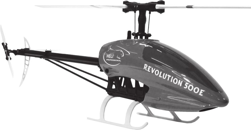
4 The battery must neither be overcharged nor exhausted. The battery is totally damaged and cannot be used anymore in case of an exhaustive discharge. Therefore do not exceed following flight times: Flight Style 3D Mode Max. Flight Time* Hover Off 6.5 Minutes Basic Flight Off 5.5 Minutes Aerobatics On 4 Minutes * Please note: the max. flight time will be shorter in cold condition or with old batteries. Heli Professional will not accept responsibility for any damage or secondary failures caused by inappropriate use and rejects any liability, as we are not in a position to supervise proper operation, handling, and maintenance. Checklist Maiden Flight Attention: This checklist is supposed to give you a short overview of the preparations for the maiden flight and does not replace the contents of this manual. Unbox and check all parts for damage. Check if all screws are fully tighten Check if all connectors are plugged in securely The main blade screws must be tightened until the blades can only be moved with a lot of force Charge the battery with the included charger according to the instructions. Notice the safety instructions and pay attention to the correct polarity of the charger, the balancer and the ESC of the model. Insert AA batteries into the Transmitter. Do not change the settings of the transmitter in any way! Position and tighten the fully charged battery according to the picture on the battery plate with the included hook and loop fasteners and secure it with O-rings in the helicopter model. Secure the balancer plug under the hook and loop fastener according to the picture. Test all functions of the model. The FBL-3X system and the transmitter are already programmed. No further settings are required. The initial startup should be done on an appropriate airfield. Local clubs generally offer the best possibilities for safe and fun helicopter flying. Checklist Regular Flights Attention: This checklist is supposed to give you a short overview of regular flights and does not replace the contents of this manual. Check all connections and screws before every flight Secure the battery with O-rings in the battery rails and connect the ESC with the battery. 4


5 To avoid the main blades from fold together when starting or landing, the main blade screws must be tighten very hard, so that the blades can only be moved with a lot of force. If the main blades fold together, they start an extreme vibration which can destroy the helicopter! If this happens, due to less tightened main blade screws, it can be stopped by pushing the pitch stick hard and fast to positive pitch (Motor must be cut off!). If you do this, you can avoid the helicopter from destroying itself. Always switch on the transmitter first! Throttle/pitch stick and other switches must be set on their zero position beforehand! Wait until the ESC and the FBL-3X system have initialized. The FBL-3X system has initialized when the swash plate has rotated once. The helicopter must stand absolutely still and leveled during this procedure. Check the function of all servos (direction of movement, etc.). Therefore, put the autorotation switch in the position lock. This prevents the motor from running unintendedly. Fly with your model. Start the landing procedure before the battery is low. Disconnect the ESC from the battery and switch off the transmitter finally. Charging the Flight Battery Charge the 4S 4250mAh lithium polymer battery only with the included charger, which is optimally adjusted to charge and balance the battery. Disregarding this procedure may cause damage to the battery, the charger and the immediate environment (danger of fire). Never charge the battery unattended! We recommend to charge and store the battery in a non-flammable environment (e.g. LiPo-bag). Pay attention to the correct polarity when connecting the charger and the balancers with the battery. Power supply: 12V car battery: Use a 12V lead gel battery to connect directly to the charger (no power adaptor necessary). 230V power supply: Use the charger only with an appropriate power adaptor (Not included. Ord. no and ). Charging the battery: 1. Disconnect the battery from the ESC and remove the battery with the battery plate from the model. 2. Connect the charger first with the 12V power supply. All LEDs must blink red and green. 3. Now connect the battery with the charger and the balancer plug of the battery with the balancer socket of the charger according to the picture. The LEDs are blinking red. 4. Choose the charging current with the knob (recommendation: 4.5A). 5. Press the start button. All LEDs must glow red. 6. When the charging is finished, you will hear a whistling sound and all LEDs must glow green. 7. Disconnect the battery from the charger and disconnect the charger from the power supply. 5


6 Inserting the flight battery Slide the battery plate including the flight battery into the battery rails of the front porch and secure it with O-rings. Sliding in the battery plate. Securing the battery plate with O-rings. Programming The FBL-3X flybarless system is already pre-programmed for your Revolution 500E. You only need to adjust a few settings in your flybarless system and your transmitter. Preparation: WARNING: Disconnect the motor and the ESC while the whole programming! Open a new model in your transmitter and choose the swashplate type H1; 1 Servo mechanic or swashplate mix off. Connect the battery with the ESC to start up the system. Connect the terminal with the FBL-3X (Place: TERM) Programming Unit After connecting the terminal unit (Art. Nr. 08.FBL-DSP) with the running FBL-3X, the Welcome menu will appear. There you can see the current software version of your FBL-3X. You can navigate and change values with the four arrow keys of the terminal. By pressing the keys you can switch between the main menus. By pressing once you can enter the choosen menu and you will see the values which can be changed. Most menus have more than one changeable value. You can switch between the values by pressing repeated. By pressing the key you can exit the sub menu. Values can be changed with the keys. Safe Settings After changing values in the FBL-3X system, you must safe them. Press and hold in any main menu (except channel monitoring) first and then. You will see ALL PARAMETERS SAVED. WARNING: If you want to cancel the changes, it is not sufficient to remove the terminal. You must disconnect the power from the FBL-3X to cancel all unsaved settings. WARNING: The terminal must be removed before flying the helicopter! Change Language The standard language of the FBL-3X is english. Press until the main menu Miscellaneous Settings. Choose the point language and change it to German or French. Save the changes. 6
7 Connect a receiver You can use the FBL-3X on your Revolution 500E with these receiver types: Standard-receiver, SingleLine, Serial Receiver, Futaba S-Bus, Multiplex SRXL, act SX and SPEKTRUM satellites. Serial Signal, SingleLine, Futaba S-Bus, Multiplex SRXL, act SX To connect these receivers use the delivered patchwire and connect it to the place INPUT Spektrum Satellites You can connect one or two Spektrum DSM2 or DSMX satellite receivers to the 9-pin plug connector at the front side of FBL-3X. Make sure that the plugs are connected at the far right and the far left side! Some pins in the middle will remain empty. If you only use one satellite you can chose freely between the far right or far left side. Attention: Spektrum satellites must be bound to the transmitter before they can be used. Please pay attention to the point: Programm and Bind Receiver - Spektrum DSM2 Warning: To avoid interferences, we highly recommend the use of two satellites! Standard Receiver A standard receiver is connected through the included adapter cable and the patch cable. It does not matter which plug of the adapter is plugged into which channel. The channel assignment is always done in the FBL-3X menu. Of course, this may only be receiver outputs, which also have a relevant function for FBL-3X. In general this is pitch, yaw, aileron, elevation and the tail gain. Programm and Bind Receiver Choose the main menu RECEIVER ASSIGNMENTS and then by pressing right the sub menu: RX TYPE. Choose the used receiver type. IMPORTANT: After choosing the receiver type, go back to the main menu by pressing left and safe the changes. Shut the helicopter down and start it again. Spetkrum DSM2/DSMX: Use this value if you have connected one or two Spektrum satellite receivers. For this type of receiver the input channels of FBL-3X are assigned to functions automatically according the standard of Spektrum. Only if the assignment is incorrect, you have to assign the FBL-3X channels to their functions as described further below. Spektrum satellites must be bound to the transmitter before use: After choosing Spektrum DSM2/DSMX in the receiver menu, press right to enter the BIND menu. Start binding by pressing down. You will see CONNECT RECEIVER. If you allready have connected the satellites, dissconnect them now and plug them in again. The satellites start to flash to show, that they are ready for binding. Bind the satellites according to the transmitters manual. If the binding process was succesfull, the satellites will show a steady light. Note: FBL-3X can only set-up the receiver in binding mode. The binding itself is a process between transmitter and receiver. You can instead connect the satellite to a standard receiver and do the binding process this way. Once transmitter and receiver are bound, the operation with FBL-3X is possible. Single Line Receiver Use this value if you have connected a receiver of the type Single Line. For this type of receiver the input channels of FBL-3X have to be assigned to their functions as described further below Futaba S-Bus Receiver, Multiplex SRXL Receiver, act SX Receiver Use this value if you have connected a receiver of the type Futaba S-Bus, Multiplex SRXL or ACT SX. For this type of receiver the input channels of FBL-3X are assigned to functions automatically according the Futaba standard. Only if the assignment is incorrect, you have to assign the FBL-3X channels to their functions as described further below. Standard Receiver Use this value if you have connected a standard receiver. For this type of receiver the input channels of FBL-3X have to be assigned to their functions as described further below. 7
8 Channel/Function assignment The FBL-3X expects all functions without any mixer on separate channels. Hence, the output channels of a receiver directly represent the functions Pitch, Tail, Elevator, Aileron and gain. To set FBL-3X in a position to correctly process the functions, one has to inform FBL-3X, which function is fed into FBL-3X on which input channel. In some cases this is done by the proprietary sequence of the manufacturer (see above). In case of standard receivers and for Single Line receivers, there is no such sequence, it has to be assigned individually. To do so, go ahead as follows. Select main menu Receiver Assignments With button move to sub menu Pitch. You will see Pitch in the top line and Channel 1 combined with a value in the lower line. Move the pitch stick and observe the value. If it follows the stick movement, the assigning of Pitch is already correct, if not hit button once. In the lower line of the display you will see Channel 2. Move the pitch stick again and observe the value. Repeat the procedure until you found the Pitch channel. Select the next function (Tail) with the button and repeat the procedure as abouve until you fond the related channel. Repeat this for all functions. Save the changes after finishing the channel asignment. Channel Monitoring / Transmitter-Programming Agility: The speed of performing nick and roll inputs while flying is changed by adjusting the servo end point of these functions. The higher the end-point, the faster the helicopter will turn. If you reduce the servo way in your transmitter, the servos will make exactly the same way as before. But the helicopter will turn slower in air. Enter the menu CHANNEL MONITORING. Here you can see, which inputs the FBL-3X receives. The meaning of the shortcuts is: T = Tail, CP = Collective Pitch, E = Elevator (Nick) and A = Aileron (Roll). The small t in the first line is for tail gain, the small h is for the head gain. To check the input/ agility from roll, move the roll stick complete to the right. You will see the value A changing. To adjust the value, you must adjust the servo end-point of the roll servo in your transmitter. Adjust the servo ways like this for the first flight (Values according to terminal) Nick and Roll: E+/-100 A+/-100 Tail: T+/-100 Pitch: CP+/-100 Note: Every transmitter manufacturer uses different values for 100% servo way. Therefore it is very important to check the values in the channel monitoring menu and not in the transmitters menu! Adjust the tail gain in your transmitter, to 120 in the channel monitoring menu (Letter: small t). www. 8
9 Transmitter Programming Throttle/Pitchcurve Heli-Professional suggests you to program 3 Throttle / Pitchcurves in your transmitter. F Flight Mode 1: This flight mode is used for takeoff, hoovering and for landing. Adjust the throttle and pitchcurve for flightmode 1 this: Flight Mode 1 / Hoover Point Pitchcurve Pitchangle Throttle 1 35% -4 0% % -2 25% 3 50% 0 65% 4 75% 6 85% 5 100% % Flight Mode 2: This flight mode is used for basic flights and soft aerobatics. Adjust the throttle and pitchcurve for flightmode 2 like this: Flight Mode 2 / Basic Flight Point Pitchcurve Pitchangle Throttle 1 0% % 2 25% -6 85% 3 50% 0 80% 4 75% 6 85% 5 100% 12 90% Flight Mode 3 This flight mode is used for aerobatics and 3D flight. Adjust the throttle and pitchcurve for flightmode 3 like this: Flight Mode 3 / Aerobatics Point Pitchcurve Pitchangle Throttle 1 0% % 2 25% -6 90% 3 50% 0 85% 4 75% 6 90% 5 100% % Note: The given values are based on transmitters with curves from 0-100%. If the ranges in your transmitter reach from -100 to +100, -100 is equal to 0%, 0 is equal to 50% and +100 is equal to 100%. Warning: Before the first flight you must set the throttle range in your ESC. Please refer to the ESC manual! All other values of the FBL-3X are already programmed and need no adjustments. You can find the complete manual of the Xelaris FBL-3X on Downloads. 9
 and rudder/tail rotor pitch")
 and aileron/roll (left/right).")
10 You need to check the steering before the first flight. Mode 2: Control Test The left stick controls collective pitch/throttle (climb/sink) and rudder/tail rotor pitch (left/right). The right stick controls the swash plate movements, i.e. elevator (forwards/backwards) and aileron/roll (left/right). Mode 1: The left stick controls the swash plate movements, i.e. elevator (forwards/backwards) and aileron/roll (left/right). Rudder (left) Rudder (right) 10
 Aileron / Roll (left) The following control test is explained on the basis of mode 2!")


11 The right stick controls collective pitch/throttle (climb/sink) and rudder/tail rotor pitch (left/right). Aileron / Roll (left) Aileron / Roll (left) The following control test is explained on the basis of mode 2! If you use mode 1, the control commands change accordingly. Place the helicopter on a flat surface and position yourself in a way that you can look at the model from all angles. 1. It is absolutely necessary to disconnect the plugs between motor and ESC. 2. Put the pitch/throttle stick into its lowest position and switch on the transmitter. 3. Connect the flight battery and the ESC and wait until both the ESC and the FBL-3X have initialized. 11

.")


12 4. Put the autorotation switch into the position Lock! 5. Move the pitch stick all the way up and down and check the vertical movement of the swash plate on the main rotor shaft as well as the ease of movement of all linkage rods. If the function works in the opposite direction reverse the Pitch channel in your transmitter. Mode 2: Topmost position of the pitch/throttle stick (seen from the left side in direction of flight). Mode 2: Lowest position of the pitch/throttle stick. (seen from the left side in direction of flight). 6. Check the rudder/tail rotor pitch function by moving the stick all the way from left to right. Check the ease of movement of the tail pitch control lever on the tail rotor shaft. When you move the stick to the left, the tail pitch control lever must move to the right and vice versa. If the function works in the opposite direction reverse the Rudder channel in your transmitter. Mode 2: Left position of the rudder/tail rotor pitch stick. Mode 2: Right position of the rudder/tail rotor pitch stick. 7. Move the elevator stick all the way up and down and check the tilt direction of the swash plate. When you move the stick forwards, the swash plate must tilt forwards (in the direction of flight) and vice versa. If the function works in the opposite direction reverse the Elevator channel in your transmitter. 12

.")
13 Mode 2: Topmost position of the elevator stick (seen from the left side in direction of flight). Mode 2: Lowest position of the elevator stick (seen from the left side in direction of flight). 8. Move the aileron/roll stick all the way from left to right and check the tilt direction of the swash plate. When you move the stick to the left, the swash plate must tilt to the left (in the direction of flight) and vice versa. If the function works in the opposite direction reverse the Roll channel in your transmitter. Mode 2: Left position of the aileron stick (seen from behind the swash plate in direction of flight). Mode 2: Right position of the aileron stick (seen from behind the swash plate in direction of flight). If a function doesn t work in the right direction. You must reverse the whole channel in your transmitter Servo Reverse. If it doesn t work according to the given pictures. Please contact your retailer. 13
14 Control Functions During Flights This chapter explains the basic control/steering functions of the helicopter based on Mode 2. In general: Steering one of the four control functions (e.g. pitch/throttle) does always lead to a change in the overall flight position of the model. This means that you always have to steer the other three control functions accordingly to keep the helicopter in the desired flight position. Important: Steering the rudder/tail rotor pitch function changes the position of the tail boom, but in fact, you always steer the nose of the model (see rudder/tail rotor pitch function for more details). Pitch/Throttle Function If you move the pitch/throttle stick forwards, the main rotor blade angle will change and the helicopter will climb. If you move the pitch/throttle stick backwards, the main rotor blade angle will change and the helicopter will descend. Rudder/Tail Rotor Pitch Function If you move the rudder/tail rotor pitch stick to the left, the tail blade angle will change and the helicopter will turn around its vertical axis. Consequently, the nose of the helicopter will turn to the left in the direction of flight. 14

15 If you move the rudder/tail rotor pitch stick to the right, the tail blade angle will change and the helicopter will turn around its vertical axis. Consequently, the nose of the helicopter will turn to the right in the direction of flight. Elevator Function If you move the elevator stick forwards, the main rotor blade angle will change and the helicopter will turn around its lateral axis. Consequently, the helicopter will tilt forwards and fly forwards. If you move the elevator stick backwards, the main rotor blade angle will change and the helicopter will turn around its lateral axis. Consequently, the helicopter will tilt backwards and fly backwards. 15


16 Aileron/Roll Function If you move the aileron/roll stick to the left, the main rotor blade angle will change and the helicopter will turn around its longitudinal axis. Consequently, the helicopter will tilt and fly to the left. If you move the aileron/roll stick to the right, the main rotor blade angle will change and the helicopter will turn around its longitudinal axis. Consequently, the helicopter will tilt and fly to the right. 16


17 Trim Functions The trim functions allow you to adjust the flight characteristics and to avoid an unintended drift of the helicopter via the longitudinal and lateral axis. Do not trim the rudder/tail rotor pitch because this is done automatically by the gyro system. However, should the tail rotor drift away unintentionally, switch off the helicopter, disconnect all plugs and then, reconnect all plugs so that the ESC and the FBL-3X gyro system can initialize again. Nevertheless, the helicopter will never remain absolutely stable in its hovering position even with a perfect trimming. A steady correction of all control functions is always necessary to keep the helicopter in the intended flight position. Mode 2: Hovering/Normal Flight Mode and 3D/Stunt Flight Mode: Trimming the pitch/throttle is never necessary. Leave the slide control in mid-position. Mode 2: Use the elevator trim slide control if the helicopter drifts forwards or backwards when hovering with no elevator stick input. Mode 2: Use the aileron/roll trim slide control if the helicopter drifts to the left or right when hovering with no aileron/roll stick input. 17

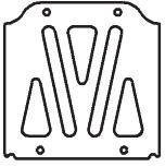
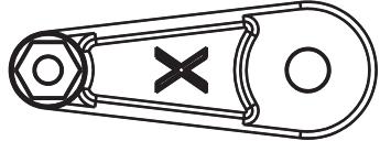
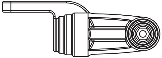
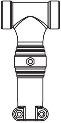
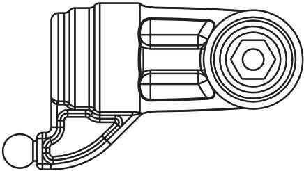
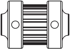
18 Preparing the Maiden Flight Although the helicopter was mounted, adjusted and tested ex works, it is necessary to check the following functions. Check the tail drive belt tension: It is sufficiently tense when you can push it down max. 5 mm in the tail rotor housing with normal force. Check the tension regularly. Tensing the tail drive belt: Loosen both M3x20 mm bolts of the tail boom housing in the frame. Loosen the M3x35 mm bolt of the stabilizer fin. Tense the tail drive belt by pulling the tail boom backwards. Level the tail boom exactly horizontally and tighten all bolts again. A too loose or too tense tail drive belt can wear out quickly or can even jump out of its guidance (failure of the tail rotor). Check the fastenings of all electronical parts and the wiring. Cables must not come in contact with rotating parts. Check the main and tail rotor blades for firm seating. Tighten the blades until they can only be moved with a lot of force. Check all bolts for firm seating. Tighten loose bolts if necessary. All bolts must always be secured with thread lock!. You are finally ready for the maiden flight with your new Revolution 500E RTF. Adjusting the Rotor Blade Tracking Although the rotor blade tracking was adjusted ex works, it is absolutely necessary to check it during the maiden flight and on a regular basis afterwards. In addition, you must adjust the rotor blade tracking after every crash. If the main blades are running out of track, vibrations, loss of power and instability will be the result. Hence, adjusting the rotor blade tracking is a crucial process and should be done with special diligence. Attention: Adjusting the rotor blade tracking is executed with rotating blades. Always keep a safety distance of at least 10 m between you and the model. 1. Switch the model on and bring the rotor blades to hovering speed. If both blades are running at one level, no further adjustments will be necessary. 2. If you see two rotor blade levels (as in the illustration below), adjustments will be necessary. 3. Switch the model off and wait until the blades stop to rotate. Mark one rotor blade with thin, colored duct tape or a clearly visible, colored pen. 4. Switch the model on again and bring the rotor blades to a hovering speed. You can either check the rotor blade tracking on the ground or in the air at approximately eye level. It is useful to have an assistant who eyeballs the rotor blade tracking. By targeting the marked rotor blade, you can easily spot whether the rotor blade is running out of track upwards or downwards. 5. Bring the rotor blades to a standstill. 6. A: The rotor blade, which runs out of track upwards, has too much pitch. This means that you have to shorten the pitch linkage rod between the blade holder and the swash plate by screwing in one ball link for one full rotation. Never screw in the ball link for only half a rotation! 7. B: The rotor blade, which runs out of track downwards, has not enough pitch. This means you have to lengthen the pitch linkage rod between the blade holder and the swash plate by unscrewing one ball link for one full rotation. Never unscrew the ball link for only half a rotation! Change the lengths of the linkage rods only on one rotor blade at a time and check the rotor blade tracking again. 8. Repeat this procedure until the rotor blade tracking is adjusted almost perfectly. Minimal deviations do not compromise the flight characteristics. 18
19 Manual xelaris 80A Brushless ESC Thanks for purchasing a Xelaris Brushless Electronic Speed Controller (ESC). High power system for RC model is very dangerous, please read this manual carefully. In that we have no control over the correct use, installation, application, or maintenance of our products, no liability shall be assumed nor accepted for any damages, losses or costs resulting from the use of the product. Any claims arising from the operating, failure or malfunctioning etc. will be denied. We assume no liability for personal injury, property damage or consequential damages resulting from our product or our workmanship. As far as is legally permitted, the obligation to compensation is limited to the invoice amount of the affected product. Specifications: Current: 80A Peaks: 100A BEC: Switch BEC BEC output: 5V 4A Cells: 2 4 LiPo Cells / 5 12 NiMH Cells Weight: 82g Size (L x W x H) 86x38x12 Programmable Items (The option written in bold font is the default setting): 1. Brake SettingEnabled / Disabled 2. Battery TypeLipo / NiMH 3. Low Voltage Protection Mode(Cut-Off Mode): Soft Cut-Off (Gradually reduce the output power) /Cut-Off (Immediately stop the output power) 4. Low Voltage Protection Threshold(Cut-Off Threshold)Low / Medium / High 1) For lithium battery, the battery cell number is calculated automatically. Low / medium / high cutoff voltage for each cell is: 2.85V/3.15V/3.3V. For example: For a 3S Lipo, when Medium cutoff threshold is set, the cut-off voltage will be: 3.15*3=9.45V 2) For NiMH battery, low / medium / high cutoff voltages are 0%/50%/65% of the startup voltage (i.e. the initial voltage of battery pack), and 0% means the low voltage cut-off function is disabled. For example: For a 10 cells NiMH battery, fully charged voltage is 1.44*6=8.64V, when Medium cut-off threshold is set, the cut-off voltage will be:8.64*50%=4.32v 5. Startup ModeNormal /Soft /Super-Soft (300ms / 1.5s / 3s) Normal mode is suitable for fixed-wing aircraft. Soft or Super-soft modes are suitable for helicopters. The initial acceleration of the Soft and Super-Soft modes are slower, it takes 1.5 second for Soft startup or 3 seconds for Super-Soft startup from initial throttle advance to full throttle. If the throttle is completely closed (throttle stick moved to bottom position) and opened again (throttle stick moved to top position) within 3 seconds after the first startup, the re-startup will be temporarily changed to normal mode to get rid of the chance of a crash caused by slow throttle response. This special design is suitable for aerobatic flight when quick throttle response is needed. 6. TimingLow / Medium / High,( 3.75 /15 /26.25 ) Usually, low timing is suitable for most motors. To get higher speed, High timing value can be chosen. Begin to use your ESC IMPORTANT! Because different transmitter has different throttle range, please calibrate throttle range before flying. Throttle range setting: (Throttle range should be reset whenever a new transmitter is being used) Switch on the transmitter, move throttle stick to the top position Connect battery pack to the ESC, and wait for about 2 seconds The Beep-Beep- tone should be emitted, means the top point of throttle range has been confirmed Move throttle stick to the bottom position, several beep- tones should be emitted to present the amount of battery cells A long Beep- tone should be emitted, means the lowest point of throttle range has been correctly confirmed Normal startup procedure: Move throttle stick to bottom position and then switch on transmitter. Connect battery pack to ESC, special tone like 123 means power supply is OK Several beep- tones should be emitted to present the amount of lithium battery cells When self-test is finished, a long beep----- tone should be emitted Move throttle stick upwards to go flying Protection Function 1. Start up failure protection: If the motor fails to start within 2 seconds of throttle application, the ESC will cut-off the output power. In this case, the throttle stick MUST be moved to the bottom again to restart the motor. (Such a situation happens in the following cases: The connection between ESC and motor is not reliable, the propeller or the motor is blocked, the gearbox is damaged, etc.) 2. Over-heat protection: When the temperature of the ESC is over about 110 Celsius degrees, the ESC will reduce the output power. 3. Throttle signal loss protection: The ESC will reduce the output power if throttle signal is lost for 1 second, further loss for 2 seconds will cause the output to be cut-off completely. 19
20 Manual xelaris 80A Brushless ESC Trouble shooting Trouble Possible Reason Action After power on, motor does not work, no sound is emitted The connection between battery pack and ESC is not correct Check the power connection. Replace the connector. After power on, motor does not work, such an alert tone is emitted: beep-beep-, beep-beep-,beep-beep- (Every beep-beep- has a time interval of about 1 second) Input voltage is abnormal, too high or too low. Check the voltage of battery pack After power on, motor does not work, such an alert tone is emitted: beep-, beep-, beep- (Every beep- has a time interval of about 2 seconds) Throttle signal is irregular Check the receiver and transmitter Check the cable of throttle channel After power on, motor does not work, such an alert tone is emitted: beep-, beep-, beep- (Every beep- has a time interval of about 0.25 second) After power on, motor does not work, a special tone is emitted after 2 beep tone (beep-beep-) The motor runs in the opposite direction The throttle stick is not in the bottom (lowest) position Direction of the throttle channel is reversed, so the ESC has entered the program mode The connection between ESC and the motor need to be changed. Move the throttle stick to bottom position Set the direction of throttle channel correctly Swap any two wire connections between ESC and motor Program the ESC with your transmitter (4 Steps) Note: Please make sure the throttle curve is set to 0 when the throttle stick is at bottom position and 100% for the top position. 1. Enter program mode 2. Select programmable items 3. Set item s value (Programmable value) 4. Exit program mode 1. Enter program mode 1) Switch on transmitter, move throttle stick to top position, connect the battery pack to ESC 2) Wait for 2 seconds, the motor should emit special tone like beep-beep- 3) Wait for another 5 seconds, special tone like should be emitted, which means program mode is entered 2. Select programmable items: After entering program mode, you will hear 8 tones in a loop with the following sequence. If you move the throttle stick to bottom within 3 seconds after one kind of tones, this item will be selected. 1. beep brake (1 short tone) 2. beep-beep- battery typ (2 short tone) 3. beep-beep-beep- cutoff mode (3 short tone) 4. beep-beep-beep-beep- cutoff threshold (4 short tone) 5. beep----- startup mode (1 long tone) 6. beep-----beep- timing (1 long 1 short) 7. beep-----beep-beep- set all to default (1 long 2 short) 8. beep-----beep----- exit (2 long tone) 3. Set item value (Programmable value): You will hear several tones in loop. Set the value matching to a tone by moving throttle stick to top when you hear the tone, then a special tone emits, means the value is set and saved. (Keeping the throttle stick at top, you will go back to Step 2 and you can select other items; or moving the stick to bottom within 2 seconds will exit program mode directly) Tones beep- beep-beep- beep-beep-beep Items 1 short tone 2 short tones 3 short tones Brake Off On - Battery type Lipo NiMH - Cutoff mode Soft-Cut Cut-Off - Cutoff threshold Low Medium High Start mode Normal Soft Super soft Timing Low Medium High 4. Exit program mode There are 2 ways to exit program mode: 1. In step 3, after special tone, please move throttle stick to the bottom position within 2 seconds. 2. In step 2, after tone beep-----beep----- (ie.the item #8), move throttle stick to bottom within 3 seconds. 20
21
22
23
24

25
26
27
28
29
30
31
32
33
34
35
36
37
38
39
40
41
REVOLUTION 500E RTF Manual v1.0
 REVOLUTION 500E RTF Manual v1.0 CONTENTS Page Introduction 2 Product Contents 2 Specifications 3 General Safety Instructions 3 Flight Battery Safety Instructions 3-4 Checklist Maiden Flight 4 Checklist
20/40/60A V2 Brushless Electronic Speed Controller INSTRUCTION MANUAL. Copyright 2013 KY MODEL Company Limited.
 20/40/60A V2 Brushless Electronic Speed Controller INSTRUCTION MANUAL www.copterx.com Copyright 2013 KY MODEL Company Limited. MENU 1. 2. 3. 4. 5. 6. 7. Table of content Introduction Specifications Programmable
Manual of RCX Brushless Motor Speed Controller (G Series)
") Manual of RCX Brushless Motor Speed Controller (G Series) Thanks for purchasing a RCX Electronic Speed Controller (ESC).The high power system for RC model can be very dangerous, so we strongly suggest
Manual of RCX Brushless Motor Speed Controller (G Series) Thanks for purchasing a RCX Electronic Speed Controller (ESC).The high power system for RC model can be very dangerous, so we strongly suggest
REES52 MANNUAL FOR ESC 30A
 REES52 MANNUAL FOR ESC 30A Manual of RC Timer ESC 30A Brushless Motor Speed Controller Thanks for purchasing RC Timer Electronic Speed Controller (ESC). High power system for RC model can be very dangerous,
Item Number. EFUN ARF EFUN kit SPECIFICATIONS. Wingspan: 2120mm(W/O winglets) ESC: 30A. Battery: 3S 2200mAh Lipo(Not included)
 ESC: 30A. Battery: 3S 2200mAh Lipo(Not included)") Item Number EFUN ARF 301401 EFUN kit 301402 SPECIFICATIONS Wingspan: 2120mm(W/O winglets) ESC: 30A Length: 1017mm Servo: 4x 9g Flying weight: 1150g Propeller: 10x6 Motor: 2820 1000KV Radio: 4CH or above(not
Item Number EFUN ARF 301401 EFUN kit 301402 SPECIFICATIONS Wingspan: 2120mm(W/O winglets) ESC: 30A Length: 1017mm Servo: 4x 9g Flying weight: 1150g Propeller: 10x6 Motor: 2820 1000KV Radio: 4CH or above(not
USER MANUAL BRUSHLESS SPEED CONTROLLER S5-RTR ESC S5A-RTR ESC RC CARS & TRUCKS
 USER MANUAL BRUSHLESS SPEED CONTROLLER S5-RTR ESC S5A-RTR ESC RC CARS & TRUCKS Declaration Thanks for purchasing our Electronic Speed Controller (ESC). High power system for RC model can be very dangerous,
30A BLDC ESC. Figure 1: 30A BLDC ESC
 30A BLDC ESC Figure 1: 30A BLDC ESC Introduction This is fully programmable 30A BLDC ESC with 5V, 3A BEC. Can drive motors with continuous 30Amp load current. It has sturdy construction with 2 separate
User Manual. Brushless Speed Controller XERUN 80A/150A. Copyright 2009 Hobbywing Technology Co., Ltd. All Rights Reserved
 User Manual Brushless Speed Controller XERUN 80A/150A Copyright 2009 Hobbywing Technology Co., Ltd. All Rights Reserved CONTENTS DECLARATION FEATURES SPECIFICATIONS BEGIN TO USE THE NEW ESC PROGRAM THE
Specifications ASSEMBLY INSTRUCTIONS
 ASSEMBLY INSTRUCTIONS Specifications Length : 6 mm Height : 218 mm Main Blade : 325 mm Main Rotor Diameter : 723 mm Tail Rotor Diameter : 150 mm Motor Pinion Gear : 16T (14T) Main Drive Gear : 150T Main
Thank you for purchasing PA Quantum Pro Electronic Speed Controller (ESC)
") Thank you for purchasing PA Quantum Pro Electronic Speed Controller (ESC) High power systems for RC model can be very dangerous and we strongly suggest that you read this manual carefully. Precision Aerobatics
Thank you for purchasing PA Quantum Pro Electronic Speed Controller (ESC) High power systems for RC model can be very dangerous and we strongly suggest that you read this manual carefully. Precision Aerobatics
Cirtix series Brushless Speed Controller manual For RS1/RS A/ Page - 1 -
 RS1/RS20602010A/100524 Page - 1 - Thank you for purchasing the Speed Passion Cirtix series electronic speed controller (ESC). High power systems for RC models can be very dangerous, so we strongly suggest
BEC Output. Weight (g) Battery cell NiXX/Lipo
 Battery cell NiXX/Lipo") Thank you for purchasing HobbyKing Brushless Electronic Speed Controller(ESC). High power systems for RC model can be very dangerous and we strongly suggest that you read this manual carefully. HobbyKing
Thank you for purchasing HobbyKing Brushless Electronic Speed Controller(ESC). High power systems for RC model can be very dangerous and we strongly suggest that you read this manual carefully. HobbyKing
Thank you for purchasing the ZTW AL-Series Brushless Electronic Speed Controller(ESC) from
 from") Thank you for purchasing the ZTW AL-Series Brushless Electronic Speed Controller(ESC) from www.rcplanebuilder.com High power systems for RC model can be very dangerous and we strongly suggest that you
Thank you for purchasing the ZTW AL-Series Brushless Electronic Speed Controller(ESC) from www.rcplanebuilder.com High power systems for RC model can be very dangerous and we strongly suggest that you
Caution Notes. Features. Specifications. Installation. A3 3-axis Gyro & Stabilizer User Manual V1.0
 Caution Notes Thank you for choosing our products. If any difficulties are encountered while setting up or operating it, please consult this manual first. For further help, please don t hesitate to contact
Features: Enhanced throttle response, excellent acceleration, linearity and driveability
 120A/150A ESC X-Car 120A/150A Series Sensored/Sensorless Brushless ESC for 1:8 scale Car or Truck Thank you for purchasing the X-Car Brushless Electronic Speed Controller (ESC). The X-Car 1:8 Scale 120A/150A
Thank you for purchasing ZTW A-Series Brushless Electronic Speed Controller (ESC). Wires Connection:
. Wires Connection:") Thank you for purchasing ZTW A-Series Brushless Electronic Speed Controller (ESC). High power systems for RC model can be very dangerous and we strongly suggest that you read this manual carefully. ZTW
Thank you for purchasing ZTW A-Series Brushless Electronic Speed Controller (ESC). High power systems for RC model can be very dangerous and we strongly suggest that you read this manual carefully. ZTW
Model 1:8 Beast-ZTWSS120A 1:8 Beast-ZTWSS150A. PN#Model Cont.Current 120A 150A. Burst Current 760A 1080A
 Alien Power System BEAST Series Sensored/Sensorless Brushless ESC for 1:8 scale Car or Truck Thank you for purchasing the Alien Power System Brushless Electronic Speed Controller (ESC). The Alien Power
Welcome to VBar Express 5.3
 Bar Express Welcome to VBar Express 5.3 The VBar with V 5.3 Express software is an innovative product setting new standards for model helicopters in terms of flight performance and programming capacity.
Battery cell. User Current(A) NiXX/Lipo. (g)
 NiXX/Lipo. (g)") Thank you for purchasing XQ Brushless Electronic Speed Controller(ESC). High power systems for RC model can be very dangerous and we strongly suggest that you read this manual carefully. XQ Model have
Thank you for purchasing XQ Brushless Electronic Speed Controller(ESC). High power systems for RC model can be very dangerous and we strongly suggest that you read this manual carefully. XQ Model have
HOBBYKING BRUSHLESS ESC User Manual
 HOBBYKING BRUSHLESS ESC User Manual Thank you for purchasing Hobbyking Brushless Electronic Speed ControIler(ESC). High power systems for RC model can be very dangerous and we strongly suggest that you
ESC. Brushless Controller. Receiver
 ESC instruction Wires Connection: The electronic speed controller can be connected to the motor by soldering directly, or with high quality connectors. Always use new connectors, which should be soldered
PHOENIX HV Features of the Phoenix HV-45 : 2.3 Connecting the Motor. 2.4 Reversing Rotation. 2.5 Connecting the Receiver
 PHOENIX HV -45 1.0 Features of the Phoenix HV-45 : Extremely Low Resistance (.003 ohms) High rate adjustable switching (PWM) Up to 45 Amps continuous current Dual Opto-Coupled (No BEC) Up to 36 cells or
Begin to Use The New ESC: Before use the new ESC please carefully check every connections are correct or not. Yellow motor wire B Blue motor wire A
 HIMOTO ZTW Brushless Electronic Speed Control for car or truck Thank you for purchasing ZTW Brushless Electronic Speed Controller(ESC). The ZTW electronic speed control (ESC) is specifically designed for
Features: Enhanced throttle response, excellent acceleration, strong brakes and throttle linearity. Using LED program card to make adjustments.
 Thank you for purchasing the ZTW Brushless Electronic Speed Controller (ESC). The ZTW 1:10 Scale BEAST Series ESC is specifically designed for operating 4 Pole Sensorless brushless motors. This is a high
Galileo with wifi RADIO CONTROLLED QUAD-COPTER
 Galileo with wifi TM RADIO CONTROLLED QUAD-COPTER FEATURING: 1. Four-Rotor design allows great speed and maneuverability for both Indoor and Outdoor use. 2. Built-in 6-axis Gyro ensures excellent stability.
Battery cell. User Current(A) NiXX/Lipo. 20A 20A 30A 5-12 NC \ 2-4 Lipo 20 5V / 2A 23 x 33 x 6 yes
 NiXX/Lipo. 20A 20A 30A 5-12 NC \ 2-4 Lipo 20 5V / 2A 23 x 33 x 6 yes") 1 Wires Connection: The electronic speed controller can be connected to the motor by soldering directly or with high quality connectors. Always use new connectors, which should be soldered carefully to
1 Wires Connection: The electronic speed controller can be connected to the motor by soldering directly or with high quality connectors. Always use new connectors, which should be soldered carefully to
 Introduction Thank you for purchasing a Redcat P-51 model R/C aircraft! Headquartered in Phoenix, AZ; Redcat Racing is proud to have become the premier source for quality Gas, Nitro and Electric powered
30A ESC Manual. Specification: Burst
 30A ESC Manual Wires Connection: The speed controller can be connected to the motor by soldering directly or with high quality connectors. Always use new connectors, which should be soldered carefully
Galileo RADIO CONTROLLED QUAD-COPTER
 Galileo TM RADIO CONTROLLED QUAD-COPTER FEATURING: 1. Four-Rotor design allows great speed and maneuverability for both Indoor and Outdoor use. 2. Built-in 6-axis Gyro ensures excellent stability. 3. Modular
AVIATOR REMOTE CONTROL HELICOPTER
 AVIATOR REMOTE CONTROL HELICOPTER THANK YOU. Thank you for your purchase of Protocol s Aviator Remote Control Helicopter. You are about to experience the best of what remote control flight has to offer.
INSTRUCTION MANUAL. Preface. System components / extent of delivery. Issue December, Version 4.3
 INSTRUCTION MANUAL Preface Issue December, 31 2011 Version 4.3 Congratulations to your new µrondo Flybarless System and thank you for choosing µrondo. µrondo is a Flybarless System that is equally suited
BRUSHLESS CONTROLLERS FOR HELICOPTER & AIRCRAFT
 BRUSHLESS CONTROLLERS FOR HELICOPTER & AIRCRAFT www.skyrc.com YEAR INTRODUCTION Thanks for purchasing our HORNET series Electronic Speed Controller (ESC) for helicopter & aircraft. This product is incorporates
PHOENIX Features of the Phoenix-25 : 2.3 Connecting the Motor. 2.4 Reversing Rotation. 2.5 Connecting the Receiver
 Warning! High power motor systems can be very dangerous! High currents can heat wires and batteries, causing fires and burning skin. Follow the wiring directions carefully! Model aircraft equipped with
PHOENIX Features of the Phoenix-10 : 2.3 Connecting the Motor. 2.4 Reversing Rotation. 2.5 Connecting the Receiver
 Warning! High power motor systems can be very dangerous! High currents can heat wires and batteries, causing fires and burning skin. Follow the wiring directions carefully! Model aircraft equipped with
INSTRUCTION MANUAL. Single Rotor 400 size Helicopter with 2.4GHz Transmitter
 Single Rotor 400 size Helicopter with 2.4GHz Transmitter INSTRUCTION MANUAL FEATURES Factory assembled and Ready-to-fly 7-8 minute flight times! Beginner and Advanced flight modes Can be flown indoors
Radio control glider
 Radio control glider Contents SPECIFICATIONS 01 STATEMENT 02 SAFETY PRECAUTIONS 02~03 CHARGING METHOD AND CAUTIONS 03~05 ASSEMBLY 06~07 2.4GHz RADIO SYSTEM 08~10 PRE-FLIGHT INSPECTION AND ADJUSTMENT 10~11
Please read all instructions carefully before assembly and flight!
 c c Please read all instructions carefully before assembly and flight! Thank you for purchasing the. This model is designed for the intermediate to advanced flyer. The model is receiver-ready and includes
Operating Instructions
 Operating Instructions SOLO PRO 319 RTF 2.4 GHz No. NE2517 2 Operating Instructions, SOLO PRO 319 RTF 2.4 GHz No. NE2517 Explanation of specialist terms: Climb and descent ("Throttle/pitch"): This controls
When you finish the running, power off the receiver BEFORE turning off the transmitter.
 Thanks for purchasing Turnigy AQUASTAR ESC speed controllers. Turnigy AQUASTAR ESC are specifically developed to supply stable and strong power for r/c model boats beyond you expected. Please read the
Marco Cantoni. joins W3MH from Japan to describe 3D setup for the TSK MyStar series of helicopters. World Wide Web Model Helicopter
 Introduction 3D flying has become very popular in the last few years and is no longer a strange flying style for a few crazy pilots. With the new F3C rules even the most traditional and serious competition
BlackWidow Flybarless System Manual And Setup Guide
 BlackWidow Flybarless System Manual And Setup Guide Table of contents. 1. BlackWidow System Overview 2. Power Supply 3. Transmitter Settings 4. Blackwidow to Receiver Connections 5. Servo Connections 6.
1100MM P-51 Mustang ELECTRIC POWERED REMOTE CONTROL AIRPLANE ELEVENHOBBY.COM
 1100MM P-51 Mustang ELECTRIC POWERED REMOTE CONTROL AIRPLANE ELEVENHOBBY.COM WARNING: Read the ENTIRE instruction manual to become familiar with the features of the product before operating. Failure to
Manual LOGO 500 DX LOGO 500 3D LOGO 600 DX LOGO 600 3D.
 Manual LOGO 500 DX LOGO 500 3D LOGO 600 DX LOGO 600 3D www.mikado-heli.de Mikado Modellhubschrauber Friedrich-Klausing-Straße 2 14469 Potsdam Germany phone +49 (0)331 23749-0 fax +49 (0)331 23749-11 www.mikado-heli.de
1) Wire Cutters 1) Solder (Rosin Core Electronic Solder) 2) Wire Strippers 2) Battery Connector 3) watt soldering iron
 Wire Cutters 1) Solder (Rosin Core Electronic Solder) 2) Wire Strippers 2) Battery Connector 3) watt soldering iron") Thank you for purchasing the Electronic Speed Control (ESC). The V-Series ESC Line was designed to offer high power and high efficiency combined with low weight and a compact size. These instructions will
Thank you for purchasing the Electronic Speed Control (ESC). The V-Series ESC Line was designed to offer high power and high efficiency combined with low weight and a compact size. These instructions will
Battery: 1 cell 3.7V 220mAh li-po rechargeable. Weight: 48g (Battery Included) Rotor Diameter: 190mm. Length: 200mm. Height: 130mm
 Rotor Diameter: 190mm. Length: 200mm. Height: 130mm") Battery: 1 cell 3.7V 220mAh li-po rechargeable Weight: 48g (Battery Included) Rotor Diameter: 190mm Length: 200mm Height: 130mm www.heliguy.com Contents: Before you fly... 2 Lithium Battery Safety... 3
Battery: 1 cell 3.7V 220mAh li-po rechargeable Weight: 48g (Battery Included) Rotor Diameter: 190mm Length: 200mm Height: 130mm www.heliguy.com Contents: Before you fly... 2 Lithium Battery Safety... 3
ECHO. User Manual. Model: PFBD77
 ECHO User Manual Model: PFBD77 Thank you for choosing ProFlight. Please read this user manual before using this drone and keep it safe for future reference. CONTENTS Safety 3 Battery Charging 4 Transmitter
the game company ENGLISH Manual JAHRE YEARS ANS V
 the game company Manual 4 14+ 14+ JAHRE YEARS ANS V1.05 2013 the game company! Read the entire user s manual to become familiar with the characteristics of the product before using it. Incorrect use of
 Introduction Thank you for purchasing a Redcat JETiger Ducted-Fan Aircraft! Headquartered in Phoenix, AZ; Redcat Racing is proud to have become the premier source for quality Gas, Nitro and Electric powered
RADIO CONTROLLED QUAD-COPTER WITH CAMERA
 Movie - DRONE TM RADIO CONTROLLED QUAD-COPTER WITH CAMERA FEATURING: 1. Four-Rotor design allows great speed and maneuverability for both Indoor and Outdoor use. 2. Built-in 6-axis Gyro ensures excellent
Contents. Introduction. Warning. Cautions. Transmitter Features. Receiver Identification. Switch Between Left-Hand and Right-Hand Throttles
 RX-408 Contents Introduction Warning Cautions Transmitter Features Receiver Identification Switch Between Left-Hand and Right-Hand Throttles Flybar Set Assembly Battery Mounting and Adjustment Swashplate
4-CHANNEL RADIO CONTROLLED QUAD-COPTER
 DRONIUM TM 4-CHANNEL RADIO CONTROLLED QUAD-COPTER FEATURING: 1. Four-Rotor design allows great speed and maneuverability for both Indoor and Outdoor use. 2. Built-in 6-axis Gyro ensures excellent stability.
User Manual RC Electric Parts Electric Speed Controller (ESC) for Brushless Motors
 for Brushless Motors") User Manual RC Electric Parts Electric Speed Controller (ESC) for Brushless Motors Thank you for using RC Electric Parts ESC designed to meet your hobbies needs. As you'll find the ESC's settings are programmable
User Manual RC Electric Parts Electric Speed Controller (ESC) for Brushless Motors Thank you for using RC Electric Parts ESC designed to meet your hobbies needs. As you'll find the ESC's settings are programmable
TAROT ZYX 3 AXIS GYRO INSTRUCTION MANUAL
 TAROT ZYX 3 AXIS GYRO INSTRUCTION MANUAL The multi-functional flybarless ZYX high performance 3-axis gyro system made by TAROT is the lightest flybarless system. It is compatible with all 200-700 nitro
Very Fun & Easy NOTICE
 Very Fun & Easy NOTICE NOTICE All instructions, warranties and other collateral documents are subject to change at the sole discretion of our company. For up-to-date product literature, Visit our website
SK-GPS Instruction Manual. Rev August 1, 2014
 SK-GPS Instruction Manual Rev. 1.10 August 1, 2014 Table of Contents Safety...1 Box Contents...2 Getting Started...3 SK-GPS Internal Blue LED States...3 Swash Bump at Init...3 Mounting the SK-GPS...4 Connecting
PHOENIX ENIX Features of the Phoenix-60 : 2.3 Connecting the Motor. 2.4 Reversing Rotation. 2.5 Connecting the Receiver
 PHOENIX ENIX-60 Warning! High power motor systems can be very dangerous! High currents can heat wires and batteries, causing fires and burning skin. Follow the wiring directions carefully! Model aircraft
INSTRUCTION MANUAL WARNING
 INSTRUCTION MANUAL WARNING Please make sure you read the entire instruction manual to become familiar with the features of your aircraft before operating. Failure to operate this product correctly can
USER GUIDE - SUPPLEMENTAL
 USER GUIDE - SUPPLEMENTAL CONTENTS 5 Instructions for RX2702V receiver... 2 5.3 Channel connection of receiver... 2 10 Walkera V450D01 Flybarless System Setting RX2702V... 3 10.5 Flybarless system setting...
VERT 1 VERTICAL TAKE OFF / LANDING RC PLANE
 VERT 1 VERTICAL TAKE OFF / LANDING RC PLANE THANK YOU. Thank you for your purchase of Protocol s Vert I Vertical Take Off / Landing RC Plane. You are about to experience the best of what remote control
PHOENIX Amp Brushless Sensorless Speed Control. 1.0 Features of the Phoenix-25 : 2.3 Connecting the Motor. 2.4 Reversing Rotation
 1.0 Features of the Phoenix-25 : Extremely Low Resistance (.013 ohms) High rate (7 KHz) switching (PWM) Up to 25 Amps continuous current with proper air flow, 35 amps surge Five to eight cells with four
Brief introduction
 P-51D MUSTANG Brief introduction----------------------------------------------------------------------------03 Specifications---------------------------------------------------------------------------------03
Operation Manual 3-Axis Stabilization System for Fixed Wing Model Aircraft
 Operation Manual -Axis Stabilization System for Fixed Wing Model Aircraft Table of Contents Introduction 2 Safety Instructions 2 Product Layout 2 HGXA Overview 2 LED Display Overview Specifications Features
Scorpion User guide for Commander Series ESC s
 Scorpion User guide for Commander Series ESC s. The Commander 6V SBEC series feature a inbuilt switching BEC that will convert the voltage from your battery pack to.7 volts to power your receiver and servos.
LOTUS RC. T580P Basic Quad copter Manual Version (25 Aug 2011) (Internal document)
 (Internal document)") LOTUS RC www.lotusrc.com T580P Basic Quad copter Manual Version 1.0 (Internal document) (25 Aug 2011) Safety Precautions: 1. Please read this manual before building and flying the aircraft. 2. The product
LOTUS RC www.lotusrc.com T580P Basic Quad copter Manual Version 1.0 (Internal document) (25 Aug 2011) Safety Precautions: 1. Please read this manual before building and flying the aircraft. 2. The product
Version 3.0 INSTRUCTION MANUAL
 Version 3.0 INSTRUCTION MANUAL 1 BEASTX be absolute stable Version 3.0 INSTRUCTION MANUAL 4 CONTENTS CONTENTS... 4 SAFETY NOTES... 6 GENERAL INFORMATION... 8 1. INTRODUCTION... 9 2. BOX CONTENT... 10
FIRE PHOENIX RADIO CONTROLLED AIRPLANE
 FIRE PHOENIX RADIO CONTROLLED AIRPLANE ASSEMBLY AND OPERATION INSTRUCTIONS YIN YAN MODEL TECH. MFT. 1 SPECIFICATIONS Material EPO Plane Battery Li-Po 1300mAh 11.1V Radio 4 Channel Wing Span 1200mm Length
Thank you for purchasing this product. Please read this manual carefully before use and retain it for your future reference.
 Thank you for purchasing this product. Please read this manual carefully before use and retain it for your future reference. Technical parameter of the helicopter Fuselage Length:80MM Gross Weight: about
INSTRUCTION MANUAL SPECIFICATIONS:
 INSTRUCTION MANUAL V913 HELICOPTER BRUSHLESS CONTENTS OF THE BOX: 1 x Helicopter 1x Remote (4x AA-batteries not included) 2x 7.4V 1500mAh Li-po battery 1x Charge station 2x Tailrotor 2x Spare blade SPECIFICATIONS:
RAVEN DRONE USER MANUAL
 RAVEN DRONE USER MANUAL PRODUCT CODE: ZXRVN www.zero-x.com.au www.zero-x.co.nz v2 Thanks for purchasing a Zero-X Raven Drone, get ready to have the time of your life! We re sure your Zero-X Raven drone
User Manual of AE-45A/50A/65A/80A Electronic Speed Controller (ESC)
") User Manual of AE-45A/50A/65A/80A Electronic Speed Controller (ESC) Thanks for purchasing our Electronic Speed Controller (ESC). High power system for RC model can be very dangerous, so please read this
User Manual of AE-45A/50A/65A/80A Electronic Speed Controller (ESC) Thanks for purchasing our Electronic Speed Controller (ESC). High power system for RC model can be very dangerous, so please read this
TRACER. User Manual. Model: PFBD97
 TRACER User Manual Model: PFBD97 Thank you for choosing ProFlight. Please read this user manual before using this drone and keep it safe for future reference. CONTENTS Safety 3 Battery Charging 4 Fitting
Warning! Before continuing further, please ensure that you have NOT mounted the propellers on the MultiRotor.
 Mission Planner Setup ( optional, do not use if you have already completed the Dashboard set-up ) Warning! Before continuing further, please ensure that you have NOT mounted the propellers on the MultiRotor.
How to Connect Your Phoenix
 Servo Type Standard or Micro High Torque or Digital 5-6 Ni cells 7-8 Ni cells 2 cell LiPo 9-10 Ni cells 3 cell LiPo >10 Ni cells >3 cell LiPo 4 4 4 Do NOT use ESC BEC 4 4 2 Do NOT use ESC BEC User guide
HM-60A User Guide HIMODEL CO., LTD
 User Guide HIMODEL CO., LTD HTTP://WWW.HIMODEL.COM Dear customer, Congratulations on your choice of a HIMODEL S HM-60A 60Amp continual brushless sensorless speed controller, which is a micro-computer controlled
Important Notes Note Recommended Equipment NOT included in kit
 Important Notes This helicopter is recommended for skilled intermediates and advanced RC helicopter flyers. Make sure to read and follow all the instructions in this manual, including all accessories.
BNF Instruction Manual
 BNF Instruction Manual EFLH3080 E-flite products are distributed exclusively by Horizon Hobby, Inc. 4105 Fieldstone Road Champaign, IL 61822 USA 2009 Horizon Hobby, Inc. US patent D578,146 Multiple patents
SKYARTEC MOSQUITO 3D PRO
 SKYARTEC MOSQUITO 3D PRO Instruction & assembly manual Specifications: This micro R/C helicopter has the most advanced capabilities. 120 degree CCPM control, collective main and tail rotors, belt tail
AERO. Meet the Aero. Congratulations on your purchase of an Aero!
 AERO Congratulations on your purchase of an Aero! Please read the following sections of this manual to get started with your new autonomous aircraft. 1 Meet the Aero 7 Fly-by-wire mode 2 Safety 8 Command
Please read all instructions carefully before assembly and flight!
 Please read all instructions carefully before assembly and flight! Thank you for purchasing the Mig-15. This model is designed for the intermediate to advanced flyer. The model is receiver ready and includes
H-King R/C scale model series. instruction manual
 H-King R/C scale model series instruction manual 1. Please read this manual carefully and follow the instructions of the manual before you use this products. SAFETY INSTRUCTIONS 2. Our airplane is not
TAROT ZYX-S2 Three-axis Gyro User Manual
 TAROT ZYX-S2 Three-axis Gyro User Manual TAROT ZYX-S2 is the newly developed precision three-axis gyro, using new MEMS angular rate sensor and 32-bit microprocessor, new control algorithms and computer
Scorpion User Guide for Commander V OPTO Series ESC
 Scorpion User Guide for Commander V OPTO Series ESC v70 Scorpion User guide for Commander V OPTO Series ESC 1.0 Connecting your ESC * for connection diagram, please refer to back of this manual SAFETY
Battery Eliminator Circuit
 User guide for all models of Phoenix, Phoenix HV, Phoenix ICE, and Phoenix Ice HV brushless controllers Safety First! Castle Creations is not responsible for your use of this product, or any damage or
INSTRUCTIONS. More fun flight with NHA-50-SB5
 450 INSTRUCTIONS More fun flight with NHA-50-SB5 JR NHA-50-SB5 brushless motor speed controllers were designed and manufactured specifically for the R/C aircrafts. For the extra ordinary high efficiency
X44 VTOL electric model plane with 4 Brushless motors
 Manual X44 VTOL electric model plane with 4 Brushless motors 9944.100 EN 2-16 Content table Introduction... 4 Service centre... 4 Intended use... 5 Package content... 5 Symbol description... 6 Safety notes...
INSTRUCTION MANUAL WARRANTY
 INSTRUCTION MANUAL Rotor Diameter: 23 in [588mm] Weight: 20.5 23 oz [580 650 g] Length: 25 in [630mm] Height: 9 in [225mm] Motor: 200W brushless, 28mm diameter Heli-Max guarantees this kit to be free from
GENERAL LINK-Module 2.4GHz
 GENERAL LINK-Module 2.4GHz Operating Instructions NE480133 The GENERAL LINK SYSTEM GENERAL LINK is a Plug-and-Play module that may be used with your FUTABA radio control system to control models from the
51in Aerobatic Series Sukhoi SU-26M Almost-Ready-to-Fly. Instruction Manual. Specifications
 51in Aerobatic Series Sukhoi SU-26M Almost-Ready-to-Fly Instruction Manual Specifications Wingspan: 51.2 in (1300mm) Length: 51.2 in (1300mm) Wing Area: 581 sq in (37.5sq dm) Flying Weight: 3.5 lb (1600g)
Flymentor 3D. User Manual SHENZHEN KDS MODEL TECHNOLOGIES CO.,LTD
 WWW.KDSMODEL.COM User Manual SHENZHEN KDS MODEL TECHNOLOGIES CO.,LTD Flymentor 3D Foreward Caution 1. Summary 1.1 Introducing 1.2 Specification 1.3 Attentions 1.4 LED status 1.5 Using flow 2. Connect to
Instruction Manual. Specifications
 Instruction Manual Specifications Length: 7.3 in (185mm) Height : 3.5 in (90mm) Main Rotor Diameter: 6.9 in (175mm) Weight with Battery: 0.7 oz (21 g) Main Motor: Micro coreless (2 installed) Battery:
Instruction Manual of DYS Elf Micro Brushless Drone
 Instruction Manual of DYS Elf Micro Brushless Drone Thanks for purchasing the DYS Elf Micro Brushless drone.the brushless system with high power for RC model can be very dangerous, so we strongly suggest
nano drone for beginners
 nano drone for beginners www.axisdrones.com By operating this device you acknowledge and accept all risks and responsibilities of the use, storage and proper disposal of any and all included lithium batteries.
* Ql! ^0f. B-17 Flying Fortress. 3 axis stabilization
 G3&nw * Ql! ^0f B-17 Flying Fortress 3 axis stabilization (HK)EASYSKY ENTERPRISE LIMITED Website: www.easy-sky.net E-mail: rcmodel@easy-sky.net sales@easy-sky.net Tel: 86-755-27891 659 Fax:86-755-27372071
LOGO 400 V-Stabi. Manual.
 Manual www.mikado-heli.de LOGO 400 V-Stabi Mikado Modellhubschrauber Friedrich-Klausing-Straße 2 14469 Potsdam Germany Phone +49 (0)331 23749-0 Fax +49 (0)331 23749-11 www.mikado-heli.de Mikado Modellhubschrauber,
INSTRUCTION MANUAL SPECIFICATIONS:
 INSTRUCTION MANUAL F939-A Specifications CONTENTS OF THE BOX: 1 x RC Airplane 1 x 2.4 GHz remote (6x AA-batteries not included) 2 x 3,7 130mAh battery 1 x Spare propeller 1 x Landing 1 x Charger SPECIFICATIONS:
Instruction Manual NOTICE
 Instruction Manual NOTICE The instruction manual, warranties and other associated documentation are subject to change without notice. Hobbico assumes no responsibility for inadvertent errors in this manual.
FOR AGES 8 AND UP. 2.4GHz 3.5CH REMOTE CONTROL HELICOPTER ITEM NO
 8+ FOR AGES 8 AND UP 2.4GHz 3.5CH REMOTE CONTROL HELICOPTER ITEM NO. 35922 INTRODUCTION Thank you for purchasing this World Tech Toys product. Please make sure you carefully read the entire manual before
Understanding the Transmitter NO.S107H -1- ON/OFF Button Left Rotation Trimming. Right rotation trimming
 3 CHANNELS GYRO REMOTE CONTROL SERIES It is strongly recommended to read the manual carefully before flying. Inapropriate operations may lead to unitended crashes or injuries (of the pilot or third parties).
64MM F-16 Fighting Falcon V2
 64MM F-16 Fighting Falcon V2 SIMPLE Simple assembly RIGID STRONG DURABLE EPO STABLE SMOOTH FLYING PERFORMANCE FMSMODEL.COM Table of Contents Introductions 3 Contents of Kit 4 Assemble the plane 5 Battery
Manual LOGO 500.
 Manual LOGO 500 www.mikado-heli.de Mikado Modellhubschrauber Friedrich-Klausing-Straße 2 14469 Potsdam Germany phone +49 (0)331 23749-0 fax +49 (0)331 23749-11 www.mikado-heli.de Mikado Model Helicopters