Amalgamation Performance Analysis of LCI and VSI fed Induction Motor Drive
|
|
|
- Evangeline Garrison
- 6 years ago
- Views:
Transcription
1 Amalgamation Performance Analysis of LC and VS fed nduction Motor Drive Dilip Kumar 1, Dinesh Kumar 2, A. K. Srivastava 3, 1 Dilip Kumar is Assistant professor of Electrical & Electronics Engineering, Saroj Educational Group Lucknow, U.P, ndia 2 Dinesh Kumar is Assistant Professor of Electrical & Electronic Engineering, KNT, Sultanpur, U.P,ndia 3 A. K. Srivastava is Assistant Professor of Electrical & Electronic Engineering, KNT, Sultanpur, U.P,ndia Abstract n this paper combination of a load-commutated inverter (LC) and a voltage-source inverter (VS) are employed for performance analysis of induction motor drive. Performance of the drive has been evaluated through the different variation in reference speed and load torque. proposed LC-based induction motor drives include the following Advantages: 1) sinusoidal motor phase current and voltage based on the instantaneous motor speed control; 2) fast dynamic response by the VS operation; and 3) elimination of motor torque pulsation. LC system improves the quality of output current and voltage waveforms and provides the faster dynamic responses. Matlab/Simulation results show the validity of the employed drive system. ndex Terms- Diode rectifier, nduction motor, Load commutated inverter (LC), SVPWM technique, Voltage source inverter (VS).. NTRODUCTON The squirrel cage induction motor is basically a simple, less costly and reliable drive and can provide excellent characteristics at a constant shaft speed. Voltage source inverter fed induction motor drives are probably the cheapest and most reliable scheme of speed control [1].The voltage source inverter fed nduction motor drives most commonly controlled through the pulse width-modulation technique. The voltage source inverter ensures simple and effective motor control since the power circuit can be operated over wide ranges of load frequency and voltage [2]. Yet, the VS, based on fast-switching insulated-gate bipolar transistors (GBTs), has shown an intrinsic weakness for high-power applications due to substantial switching losses and high of the pulse width-modulation (PWM) operation, leading to hazardous over voltages[3]-[4]. Load-commutated inverter (LC)-based induction motor drives have been used in high-power applications, because of an economical and reliable current source inverter using GBT-diode and the rugged induction motors [5]. The LC-based drive employs converter grade thyristors and utilizes soft switching by natural commutation of the GBT-diode. Therefore, it provides simplicity, robustness, cost effectiveness, and very low switching losses, resulting in a favorable topology in high-power areas [6]- [8]. Moreover, has the current-source inverter (CS) topology, it has inherent advantages of CS, such as embedded shortcircuit protection, improved converter reliability, and instantaneous regeneration ability [9]. Due to all of these features the LC-based induction motor drive improves its performance, especially in medium-to-high-power applications [10]. The schematic circuit diagram of the LC and VS fed induction motor drive as shown below in Fig.1. Three Phase 220V,60Hz Diode Rectifier Load commutated inverter Voltage source inverter LC Filter THREE PHASE NDUCTON MOTOR Fig.1 Basic circuit configuration of LC and VS fed induction motor drive. 130
2 ref Ref. speed f P speed controller max sl min sl sl Three phase supply Rectifier L LC 3.. M. e LC filter V/f control C SVPWM Generator VS e sl e Pulse encoder r Fig.2. Schematic circuit diagram of LC and VS fed induction motor drive.. SYSTEM DESCRPTON The proposed drive system consisting of a diode rectifier, an LC, a VS, an LC filter and three phase induction motor are shown in Fig. 1. The VS is connected with the LC in parallel through capacitor DC link.lc and VS energized through the same DC link output but the different element. A large inductor DC link is employed for the load commutated inverter. LC, in order to convert uncontrolled DC voltage to controlled DC current. The DC-link current regulated by the inductor is supplied to the LC. As a result, both the VS and the LC can be fed from the single-diode rectifier. The VS generates sinusoidal phase voltage to the induction motor. The amplitude and frequency of the VS output voltage is continuously regulated by the motor speed control. n addition, the phase angle of the VS output voltage is set from adjusting the firing angle of the LC to provide a safe LC commutation angle. Therefore, the leading power factor for the LC operation is entirely obtained by the VS over the whole speed range of the induction motor. Based on the leading power factor by the VS, the presented system can operate the LC without the dc-commutation circuit as well as output capacitors. Therefore,the employed system can successfully solve all problems caused by the output capacitors and the forced dccommutation circuit of the conventional LC-based induction motor. Another advantage by bringing the VS is to generate sinusoidal motor currents for all speed regions to large induction motor drives. The parallel assembly of the LC and the relatively small-size VS is expected to fulfill the highpower applications, where a stand-alone VS cannot be utilized to generate sinusoidal motor currents. n addition, the sinusoidal motor voltages are also achieved through the LC filter.. CONTROL STRATEGY A controlled block diagram of the LC and VS fed induction motor drive is shown in Fig. 3. t is composed of a three-phase diode rectifier, a load commutated inverter followed by a DClink inductor, and a three-phase voltage source inverter. The voltage source inverter is connected with the load commutated inverter in parallel. Basically, the proposed system has a combined inverter topology of a load commutated inverter and a voltage source inverter. The load commutated inverter operates in the square-wave mode with converter-grade thyristors. Consequently GBT-diode in the load commutated inverter turn on and off only once per cycle of the output current and their switching loss is negligible. 131
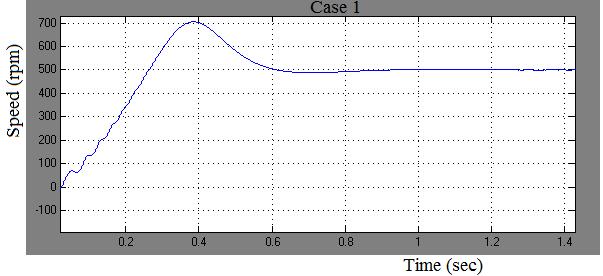
3 The main function of the voltage source inverter is injecting sinusoidal phase voltages to the induction motor. The proposed scheme can generate sinusoidal motor voltages and currents, leading to a reduction in the low-order harmonics injected into the motor. The output power distribution between them, given a certain motor power requirement, is important. A rating factor η is defined as the ratio of the load commutated inverter rating and the voltage source inverter rating. Note that two inverters are connected with the same motor phase voltage in their output terminals; by assuming that voltage drop due to the Output LC filter for the VS is negligible. Therefore, the rating factor is directly proportional to the ratio of rms values of the VS output current and the LC output current. S S THREE PHASE SUPPLY VS LC DODE RECTFER DC LNK VS. rms LC. rms LOAD COMMUTATED NVERTER VOLTAGE SOURCE NVERTER OUTPUT LC FLTER SVPWM TECHNQUE (1) THREE PHASE NDUCTON MOTOR Fig.3 Control block diagram of LC and VS fed induction motor drive. Large power voltage source inverter required for the drive results in a very high system cost. Which will limit the proposed system? From cost point of view, the load commutated inverter is not comparable to the voltage source inverter. Since the motor currents are sinusoidal quantities and the load commutated inverter currents have no ripple components in the dc link, the LC output current and the motor output current are expressed by: ( t) cos( t ( )) o mo (2) The rating factor can be derived, using (1) and (2), by 3 mo 1 { (cos ) dc 3 4 mo dc (3) 132 n addition, is the lagging power factor angle of the induction motor, which is detectable. Then, the dc link current value which minimizes the voltage source inverter rating can be obtained by setting the derivative of with respective to the dc link current to zero, d 0 d dc (4) This yields an dc link current command dc * given by: dc mo cos( ) 2 3 Equation (5) allows the dc link current control to achieve the minimum voltage source inverter power based on the motor current and phase shift between the motor current and the LC output current. This dc link current control algorithm is implemented by the dc link inductor. (5) V. PERFORMANCE NVESTGATON OF THE DRVE The circuit model is developed to examine the amalgamation performance of the LC and VS fed induction motor drive as shown in Fig.2. A three-phase squirrel-cage induction motor rated 3 hp, 220 V, 60 Hz, 1725 rpm is fed by a load commutated inverter and voltage source inverter. The firing pulses to the inverter are generated by the SVPWM modulator block of the SPS library. The chopping frequency is set to 6000 Hz and the input reference vector to magnitude-angle. Speed control of the motor is performed by the constant V/Hz block. The magnitude and frequency of the stator voltages are governed by the speed set point. By varying the stator voltage magnitude in proportion with frequency, the stator flux is kept constant. The performance of the drive is investigated for the following loading conditions: Case 1: Starting (0-500rpm) Case 2: Speed acceleration (500 rpm rpm) Case 3: Speed acceleration (1000 rpm -1400rpm) Case 4: Speed acceleration (1400 rpm -1725rpm) Case 5: Speed deceleration (1725 rpm -1400rpm) Case 6: Speed deceleration (1400 rpm -1000rpm) Case 7: Speed deceleration (1000 rpm -500rpm) Case 8: Deceleration in load torque (11.9N-m - 0N-m) Case 9: Acceleration in load torque (0N-m -18N-m) Case 10: Deceleration in load torque (18N-m - 8N-m) Case 11: Acceleration in load torque (8N-m N-m)


4 Fig 4.LC output (V) Fig. 6. Speed response of the drive for entire performance of rotor speed Fig 5.VS output (V) Fig. 7. Torque response of the drive for entire performance of load toque 133


5 Fig.8 - Rotor speed responses of the drive system for entire cases 134
 from standstill is given to the drive system. P speed controller sets the rotor speed to reference speed (500 rpm) in 1.23 sec as shown in Fig. 8 (case 1).")
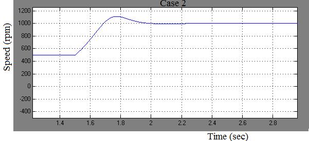
 at (500 rpm) is changed to (1000 rpm) instantly after 1.")
 and rated load torque (11.9 N-m) command is realized 12.06 N-m as shown in Fig.")
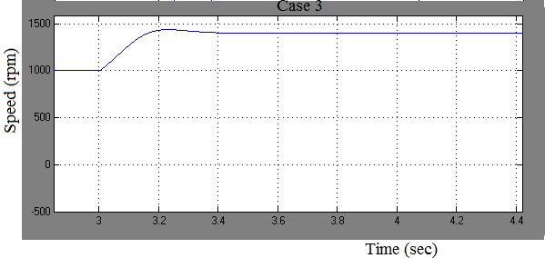
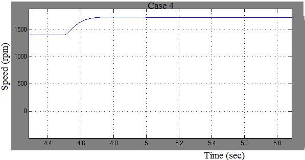
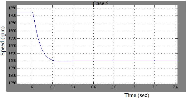
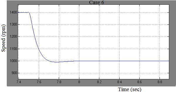
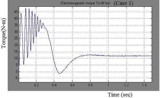
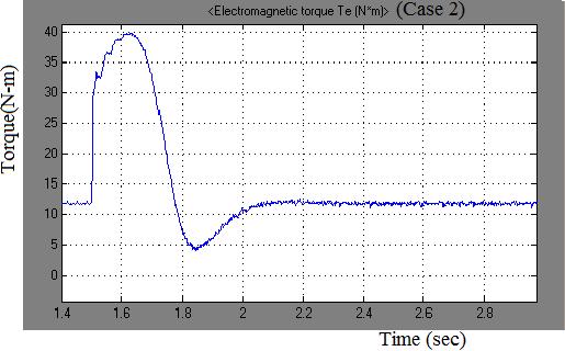
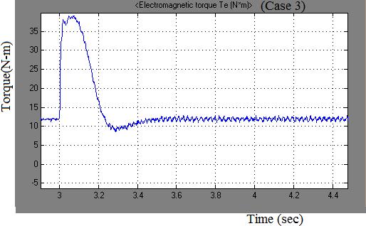
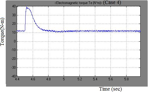
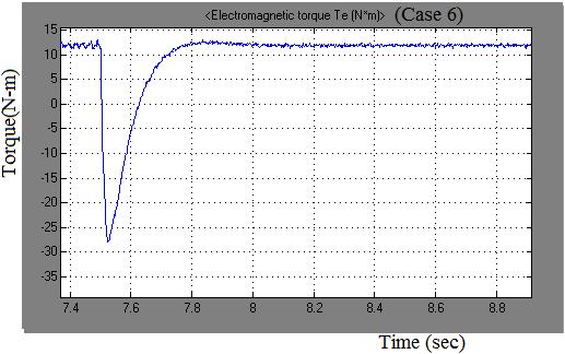
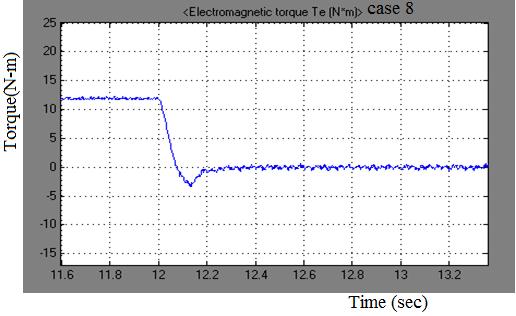
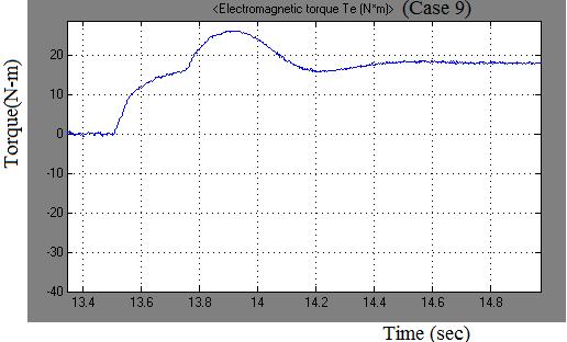
6 Fig. 9- Torque responses of the drive system for entire cases Case 1: Starting (0 to 500 rpm) nitially the motor is at stand still. A step speed command of rated value (500rpm) from standstill is given to the drive system. P speed controller sets the rotor speed to reference speed (500 rpm) in 1.23 sec as shown in Fig. 8 (case 1). The electromagnetic torque corresponding to the reference speed (500 rpm) and the rated load torque (11.9 N-m) is found to be N-m as shown in Fig 9 (case 1). Case 2: Speed acceleration (500rpm to 1000 rpm) at (500 rpm) is changed to (1000 rpm) instantly after 1.5 seconds and as a result the motor starts accelerating and settles to reference speed (1000 rpm) in 0.62 seconds as shown in Fig. 8(case 2). The electromagnetic torque corresponding to the reference speed (1000 rpm) and rated load torque (11.9 N-m) command is realized N-m as shown in Fig.9(case 2) Case 3: Speed acceleration (1000rpm to 1400 rpm) at (1000 rpm) is changed to (1400 rpm) instantly after 3 seconds the motor starts accelerating and the motor settles to reference speed (1400 rpm) in 0.51 seconds as shown in Fig.8(case 3). The steady-state value of the electromagnetic torque corresponding to the reference speed (1400 rpm) and rated load torque (11.9 N-m) command is found to be N-m as shown in Fig.9 (case 3). Case 4: Speed acceleration (1400rpm to 1725 rpm) at 1400 rpm is changed to 1725 rpm instantly after 4.5 seconds the motor starts accelerating and the motor settles to the reference speed (1725 rpm) in 0.72 seconds as shown in Fig.8(case 4). The steady-state value of the electromagnetic torque corresponding to the reference speed (1725 rpm) and rated load torque (11.9 N-m) command is observed N-m as shown in Fig.9 (case 4). 135 Case 5: Speed deceleration (1725 rpm to 1400rpm) at 1725 rpm is changed to 1400 rpm instantly after 6 seconds the motor starts decelerating and settles to reference speed (1400 rpm) in 0.39 seconds as shown in Fig.8 (case 5). The electromagnetic torque corresponding to the reference speed (1400 rpm) and rated load torque (11.9 N-m) command is found to be N-m as shown in Fig.9 (case 5). Case 6: Speed deceleration (1400 rpm to 1000 rpm) at 1400 rpm is changed to 1000 rpm instantly after 7.5 seconds the motor starts decelerating and settles to the reference speed (1000 rpm) in 0.42 seconds as shown in Fig. (case 6). The steady-state value electromagnetic torque corresponding to the reference speed command (1000 rpm) and rated torque (11.9 N-m) is observed N-m as shown in Fig.9 (case 6). Case 7: Speed deceleration (1000 rpm to 500 rpm) at 1000 rpm is changed to 500 rpm instantly after 9 seconds the motor starts decelerating and settles to reference speed command of 500 rpm in 0.74 seconds shown in Fig. 8 (case 7). The steady-state value of the electromagnetic torque corresponding to the reference speed (500 rpm) and rated load toque (11.9 N-m) command is realized 11.8 N-m as shown in Fig..7(case 7) Case 8: Decrease in load torque (11.9 N-m to 0 N-m) The rated load torque (11.9 N-m) of the motor running at 500 rpm is now reduced from 11.9 N-m to 0 N-m immediately after 13.5 seconds. The rotor speed tends to increase and it settles to 521 rpm in 0.36 seconds as depicted in Fig.8 (case 8). The steady-state value of the electromagnetic torque corresponding to the reference speed (500 rpm) and reference load torque (0 N-m) is realized N-m as shown in Fig.9 (case 8).
7 Case Case nternational Journal of Recent Development in Engineering and Technology Table. Performance Of The Drive For Each Alteration n Reference Speed Keeping Load Torque Tl=11.9 N-m Speed step from To Load torque (N-m) Rotor speed (rpm) Speed over shoot / under shoot Drive runni ng time (s) Drive settlin g time (s) Table. Performance Of The Drive For Each Alteration n Load Torque Keeping Rotor Speed = 500 rpm Torque step from to Load torqu e (N-m) Rotor speed (rpm) Speed over shoot / under shoot Drive runnin g time (s) Drive settlin g time(s ) Case 9: ncrease in load torque (0 N-m to 18 N-m) The load torque of the motor running at 500 rpm is now increased from 0 N-m to 18 N-m immediately after 15 seconds the rotor speed tends to decrease but it again settles to 500 rpm in 1.12 seconds as shown in Fig.8 (case 9). t can be observed from Fig.28 that the electromagnetic torque corresponding to reference speed (500) rpm and reference load torque (18 N-m) is found to be N-m as shown in Fig.9 (case 9). Case 10: Decrease in load torque (18 N-m to 8 N-m) The load torque of the motor running at 500 rpm is now reduced from 18 N-m to 8 N-m immediately after 16.5 seconds the rotor speed tends to increase but it again settles to 500 rpm in 0.34 seconds as depicted in Fig.8 (case 10). The steady-state value of the electromagnetic torque corresponding to reference speed (500) rpm and reference load torque (8 N-m) is found to be N-m as shown in Fig.9 (case 10). Case 11: ncrease in load torque (8 N-m to 11.9 N-m) The load torque of the motor running at 500 rpm is now increased from 8 N-m to 11.9 N-m immediately after 18 seconds the rotor speed tends to decrease but it again settles to 500 rpm in 0.29 seconds as shown in Fig.8 (case 11). t can be observed from Fig.28 that the electromagnetic torque corresponding to reference speed (500 rpm) and reference load torque (11.9 N-m) is realized to (11.95 N-m) as shown in fig.9 (case 11). V. CONCLUSON n this paper an induction motor drive based on the parallel assembly of the LC and the VS has been discussed. The performance of the Load Commutated nverter fed induction motor drive has been investigated through the MATLAB/Simulation for the different alteration in reference speed and load torque. Simulation results shows that the presented drive system provides the more satisfactory results than the conventional CS and VS
8 V. APPENDX Name plate ratings of induction motor 3-hp, three-phase, 220 V, 60Hz, 4-pole, 1725 r.p.m. Star connected. nduction motor parameters Rs = 0.435, Rr = 0.816, Ls = H Lr = 0.004H, Lm = H, J = Kg m². V. REFERENCES [1] Sangshin Kwak and Hamid A. Toliyat A Hybrid Converter System for High-Performance Large nduction Motor Drives EEE transactions on energy conversion, vol. 20, no. 3,pp , September [2] Andrzej M. Trzynadlowski and Niculina Patriciu A Hybrid, Current- Source/Voltage-Source Power nverter Circuit EEE transactions on power electronics, vol. 16, no. 6,pp ,november [3]J. R. Espinoza and G. Joos, A current-source-inverter-fed induction motor drive system with reduced losses, EEE Trans. nd. Appl., vol.34, no. 4, pp , Jul./Aug [4] S. D. Umans and H. L. Hess, Modeling and anaysis of the wanlass three phase induction motor configuration, EEE Trans. Power App. Syst., vol. PAS-102, no. 9, pp , Sep [5] H. L. Hess, D. M. Divan, and Y. Xue, Modulation strategies for a new SCR-based induction motor drive systems with a wide speed ranges, EEE Trans. nd. Appl., vol. 30, no. 6, pp , Nov./Dec [6]H. Mok, S. K. Sul, and M. H. Park, A load commutated inverter-fed induction motor drive system using a novel dc-side commutation circuit, EEE Trans. nd. Appl., vol. 30, no. 3, pp , May/Jun [7]B. Singh, K. B. Naik, and A. K. Goel, Steady state of an inverter-fed induction motor employing natural Commutation, EEE Trans. Power Electron., vol. 5, no. 1, pp , Jan [8]A. Toliyat, N. Sultana, D. S. Shet, and J. C. Moreira, Brushless permanent magnet (BPM) motor drive system using load-commutated inverter, EEE Trans. Power Electron., vol. 14, no. 5, pp , Sep [9]S. Nishikata and T. Kataoka, Dynamic control of a self-controlled synchronous motor drive system, EEE Trans. nd. Appl., vol. A-20, no.3, pp , May/Jun
PERFORMANCE AND ENHANCEMENT OF Z-SOURCE INVERTER FED BLDC MOTOR USING SLIDING MODE OBSERVER
 PERFORMANCE AND ENHANCEMENT OF Z-SOURCE INVERTER FED BLDC MOTOR USING SLIDING MODE OBSERVER K.Kalpanadevi 1, Mrs.S.Sivaranjani 2, 1 M.E. Power Systems Engineering, V.S.B.Engineering College, Karur, Tamilnadu,
QUESTION BANK SPECIAL ELECTRICAL MACHINES
 SEVENTH SEMESTER EEE QUESTION BANK SPECIAL ELECTRICAL MACHINES TWO MARK QUESTIONS 1. What is a synchronous reluctance 2. What are the types of rotor in synchronous reluctance 3. Mention some applications
International Journal of Advance Research in Engineering, Science & Technology. Comparative Analysis of DTC & FOC of Induction Motor
 Impact Factor (SJIF): 3.632 International Journal of Advance Research in Engineering, Science & Technology e-issn: 2393-9877, p-issn: 2394-2444 Volume 3, Issue 4, April -2016 Comparative Analysis of DTC
International Journal of Advanced Research in Electrical, Electronics and Instrumentation Engineering. (An ISO 3297: 2007 Certified Organization)
") Modeling and Control of Quasi Z-Source Inverter for Advanced Power Conditioning Of Renewable Energy Systems C.Dinakaran 1, Abhimanyu Bhimarjun Panthee 2, Prof.K.Eswaramma 3 PG Scholar (PE&ED), Department
Modeling and Control of Quasi Z-Source Inverter for Advanced Power Conditioning Of Renewable Energy Systems C.Dinakaran 1, Abhimanyu Bhimarjun Panthee 2, Prof.K.Eswaramma 3 PG Scholar (PE&ED), Department
International Journal of Advance Research in Engineering, Science & Technology
 Impact Factor (SJIF): 3.632 International Journal of Advance Research in Engineering, Science & Technology e-issn: 2393-9877, p-issn: 2394-2444 (Special Issue for ITECE 2016) Field Oriented Control And
Speed Control of 3-Phase Squirrel Cage Induction Motor by 3-Phase AC Voltage Controller Using SPWM Technique
 Speed Control of 3-Phase Squirrel Cage Induction Motor by 3-Phase AC Voltage Controller Using SPWM Technique V. V. Srikanth [1] Reddi Ganesh [2] P. S. V. Kishore [3] [1] [2] Vignan s institute of information
International Journal of Advance Research in Engineering, Science & Technology
 Impact Factor (SJIF): 4.542 International Journal of Advance Research in Engineering, Science & Technology e-issn: 2393-9877, p-issn: 2394-2444 Volume 4, Issue 4, April-2017 Simulation and Analysis for
SENSORLESS CONTROL OF BLDC MOTOR USING BACKEMF BASED DETECTION METHOD
 SENSORLESS CONTROL OF BLDC MOTOR USING BACKEMF BASED DETECTION METHOD A.Bharathi sankar 1, Dr.R.Seyezhai 2 1 Research scholar, 2 Associate Professor, Department of Electrical & Electronics Engineering,
STUDY ON MAXIMUM POWER EXTRACTION CONTROL FOR PMSG BASED WIND ENERGY CONVERSION SYSTEM
 STUDY ON MAXIMUM POWER EXTRACTION CONTROL FOR PMSG BASED WIND ENERGY CONVERSION SYSTEM Ms. Dipali A. Umak 1, Ms. Trupti S. Thakare 2, Prof. R. K. Kirpane 3 1 Student (BE), Dept. of EE, DES s COET, Maharashtra,
Performance Analysis of 3-Ø Self-Excited Induction Generator with Rectifier Load
 Performance Analysis of 3-Ø Self-Excited Induction Generator with Rectifier Load,,, ABSTRACT- In this paper the steady-state analysis of self excited induction generator is presented and a method to calculate
Keywords: DTC, induction motor, NPC inverter, torque control
 Research Journal of Applied Sciences, Engineering and Technology 5(5): 1769-1773, 2013 ISSN: 2040-7459; e-issn: 2040-7467 Maxwell Scientific Organization, 2013 Submitted: July 31, 2012 Accepted: September
Design and Modelling of Induction Generator Wind power Systems by using MATLAB/SIMULINK
 Design and Modelling of Induction Generator Wind power Systems by using MATLAB/SIMULINK G. Hima Bindu 1, Dr. P. Nagaraju Mandadi 2 PG Student [EPS], Dept. of EEE, Sree Vidyanikethan Engineering College,
A CURRENT-SOURCE-INVERTER-FED INDUCTION MOTOR DRIVE SYSTEM WITH REDUCED LOSSES
 A CURRENT-SOURCE-INVERTER-FED INDUCTION MOTOR DRIVE SYSTEM WITH REDUCED LOSSES ABSTRACT Avala Rohith Kumar Student(M.Tech), Electrical Dept, Gokul group of institutions, Visakhapatnam, India. This project
Synchronous Motor Drives
 UNIT V SYNCHRONOUS MOTOR DRIVES 5.1 Introduction Synchronous motor is an AC motor which rotates at synchronous speed at all loads. Construction of the stator of synchronous motor is similar to the stator
R13 SET - 1. b) Describe different braking methods employed for electrical motors. [8M]
![R13 SET - 1. b) Describe different braking methods employed for electrical motors. [8M]](/thumbs/89/100786446.jpg "R13 SET - 1. b) Describe different braking methods employed for electrical motors. [8M]") Code No:RT32026 R13 SET - 1 III B. Tech II Semester Regular Examinations, April - 2016 POWER SEMICONDUCTOR DRIVES (Electrical and Electronics Engineering) Time: 3 hours Maximum Marks: 70 Note: 1. Question
Code No:RT32026 R13 SET - 1 III B. Tech II Semester Regular Examinations, April - 2016 POWER SEMICONDUCTOR DRIVES (Electrical and Electronics Engineering) Time: 3 hours Maximum Marks: 70 Note: 1. Question
A matrix converter based drive for BLDC motor Radhika R, Prince Jose
 A matrix converter based drive for BLDC motor Radhika R, Prince Jose Abstract This paper presents a matrix converter based drive for BLDC motor. Matrix converter is a popular direct conversion method.
St.MARTIN S ENGINEERING COLLEGE Dhulapally, Secunderabad
 St.MARTIN S ENGINEERING COLLEGE Dhulapally, Secunderabad-500 014 Subject: STATIC DRIVES Class : EEE III TUTORIAL QUESTION BANK Group I QUESTION BANK ON SHORT ANSWER QUESTION UNIT-I 1 What is meant by electrical
Simulation of Indirect Field Oriented Control of Induction Machine in Hybrid Electrical Vehicle with MATLAB Simulink
 Simulation of Indirect Field Oriented Control of Induction Machine in Hybrid Electrical Vehicle with MATLAB Simulink Kohan Sal Lotf Abad S., Hew W. P. Department of Electrical Engineering, Faculty of Engineering,
Modeling and Simulation of Five Phase Inverter Fed Im Drive and Three Phase Inverter Fed Im Drive
 RESEARCH ARTICLE OPEN ACCESS Modeling and Simulation of Five Phase Inverter Fed Im Drive and Three Phase Inverter Fed Im Drive 1 Rahul B. Shende, 2 Prof. Dinesh D. Dhawale, 3 Prof. Kishor B. Porate 123
Field Oriented Control of Permanent Magnet Synchronous Motor
 Available Online at www.ijcsmc.com International Journal of Computer Science and Mobile Computing A Monthly Journal of Computer Science and Information Technology IJCSMC, Vol. 3, Issue. 3, March 2014,
General Purpose Permanent Magnet Motor Drive without Speed and Position Sensor
 General Purpose Permanent Magnet Motor Drive without Speed and Position Sensor Jun Kang, PhD Yaskawa Electric America, Inc. 1. Power consumption by electric motors Fig.1 Yaskawa V1000 Drive and a PM motor
EEE3441 Electrical Machines Department of Electrical Engineering. Lecture. Introduction to Electrical Machines
 Department of Electrical Engineering Lecture Introduction to Electrical Machines 1 In this Lecture Induction motors and synchronous machines are introduced Production of rotating magnetic field Three-phase
COLLEGE OF ENGINEERING DEPARTMENT OF ELECTRICAL AND ELECTRONICS ENGINEERING QUESTION BANK SUBJECT CODE & NAME : EE 1001 SPECIAL ELECTRICAL MACHINES
 KINGS COLLEGE OF ENGINEERING DEPARTMENT OF ELECTRICAL AND ELECTRONICS ENGINEERING QUESTION BANK SUBJECT CODE & NAME : EE 1001 SPECIAL ELECTRICAL MACHINES YEAR / SEM : IV / VII UNIT I SYNCHRONOUS RELUCTANCE
INSTITUTE OF AERONAUTICAL ENGINEERING (Autonomous) Dundigal, Hyderabad DEPARTMENT OF ELECTRICAL AND ELECTRONICS ENGINEERING
 Dundigal, Hyderabad DEPARTMENT OF ELECTRICAL AND ELECTRONICS ENGINEERING") Course Name Course Code Class Branch INSTITUTE OF AERONAUTICAL ENGINEERING (Autonomous) Dundigal, Hyderabad - 500 0 DEPARTMENT OF ELECTRICAL AND ELECTRONICS ENGINEERING : Static Drives : A60225 : III -
Course Name Course Code Class Branch INSTITUTE OF AERONAUTICAL ENGINEERING (Autonomous) Dundigal, Hyderabad - 500 0 DEPARTMENT OF ELECTRICAL AND ELECTRONICS ENGINEERING : Static Drives : A60225 : III -
Australian Journal of Basic and Applied Sciences. Resonant Power Converter fed Hybrid Electric Vehicle with BLDC Motor Drive
 ISSN:1991-8178 Australian Journal of Basic and Applied Sciences Journal home page: www.ajbasweb.com Resonant Power Converter fed Hybrid Electric Vehicle with BLDC Motor Drive 1 Balamurugan A. and 2 Ramkumar
Modeling and Simulation of BLDC Motor using MATLAB/SIMULINK Environment
 Modeling and Simulation of BLDC Motor using MATLAB/SIMULINK Environment SudhanshuMitra 1, R.SaidaNayak 2, Ravi Prakash 3 1 Electrical Engineering Department, Manit Bhopal, India 2 Electrical Engineering
Performance analysis of low harmonics and high efficient BLDC motor drive system for automotive application
 J. Acad. Indus. Res. Vol. 1(7) December 2012 379 RESEARCH ARTICLE ISSN: 2278-5213 Performance analysis of low harmonics and high efficient BLDC motor drive system for automotive application M. Pandi maharajan
Development of Electric Scooter Driven by Sensorless Motor Using D-State-Observer
 Page 48 Development of Electric Scooter Driven by Sensorless Motor Using D-State-Observer Ichiro Aoshima 1, Masaaki Yoshikawa 1, Nobuhito Ohnuma 1, Shinji Shinnaka 2 Abstract This paper presents a newly
Model Predictive Control of Back-to-Back Converter in PMSG Based Wind Energy System
 Model Predictive Control of Back-to-Back Converter in PMSG Based Wind Energy System Sugali Shankar Naik 1, R.Kiranmayi 2, M.Rathaiah 3 1P.G Student, Dept. of EEE, JNTUA College of Engineering, 2Professor,
ECE1750, Spring Motor Drives and Other
 ECE1750, Spring 2018 Motor Drives and Other Applications 1 Three-Phase Induction Motors Reliable Rugged Long lived Low maintenance Efficient (Source: EPRI Adjustable Speed Drives Application Guide) The
Comparative Study of Maximum Torque Control by PI ANN of Induction Motor
 Comparative Study of Maximum Torque Control by PI ANN of Induction Motor Dr. G.Madhusudhana Rao 1 and G.Srikanth 2 1 Professor of Electrical and Electronics Engineering, TKR College of Engineering and
ENHANCEMENT OF ROTOR ANGLE STABILITY OF POWER SYSTEM BY CONTROLLING RSC OF DFIG
 ENHANCEMENT OF ROTOR ANGLE STABILITY OF POWER SYSTEM BY CONTROLLING RSC OF DFIG C.Nikhitha 1, C.Prasanth Sai 2, Dr.M.Vijaya Kumar 3 1 PG Student, Department of EEE, JNTUCE Anantapur, Andhra Pradesh, India.
Study of Motoring Operation of In-wheel Switched Reluctance Motor Drives for Electric Vehicles
 Study of Motoring Operation of In-wheel Switched Reluctance Motor Drives for Electric Vehicles X. D. XUE 1, J. K. LIN 2, Z. ZHANG 3, T. W. NG 4, K. F. LUK 5, K. W. E. CHENG 6, and N. C. CHEUNG 7 Department
LOAD SHARING WITH PARALLEL INVERTERS FOR INDUCTION MOTOR DRIVE APPLICATION
 International Journal of Electrical and Electronics Engineering Research (IJEEER) ISSN(P): 2250-155X; ISSN(E): 2278-943X Vol. 7, Issue 1, Feb 2017, 33-40 TJPRC Pvt. Ltd. LOAD SHARING WITH PARALLEL INVERTERS
ISSN: X Tikrit Journal of Engineering Sciences available online at:
 Taha Hussain/Tikrit Journal of Engineering Sciences 22(1) (2015)45-51 45 ISSN: 1813-162X Tikrit Journal of Engineering Sciences available online at: http://www.tj-es.com Analysis of Brushless DC Motor
INTERNATIONAL JOURNAL OF ELECTRICAL ENGINEERING & TECHNOLOGY (IJEET)
") INTERNATIONAL JOURNAL OF ELECTRICAL ENGINEERING & TECHNOLOGY (IJEET) Proceedings of the 2 nd International Conference on Current Trends in Engineering and Management ICCTEM -2014 ISSN 0976 6545(Print)
INTERNATIONAL JOURNAL OF ELECTRICAL ENGINEERING & TECHNOLOGY (IJEET) Proceedings of the 2 nd International Conference on Current Trends in Engineering and Management ICCTEM -2014 ISSN 0976 6545(Print)
Analysis of Torque and Speed Controller for Five Phase Switched Reluctance Motor
 Analysis of Torque and Speed Controller for Five Phase Switched Reluctance Motor Ramesh Kumar. S 1, Dhivya. S 2 Assistant Professor, Department of EEE, Vivekananda Institute of Engineering and Technology
Question Bank ( ODD)
") Programme : B.E Question Bank (2016-2017ODD) Subject Semester / Branch : EE 6703 SPECIAL ELECTRICAL MACHINES : VII-EEE UNIT - 1 PART A 1. List the applications of synchronous reluctance motors. 2. Draw
Programme : B.E Question Bank (2016-2017ODD) Subject Semester / Branch : EE 6703 SPECIAL ELECTRICAL MACHINES : VII-EEE UNIT - 1 PART A 1. List the applications of synchronous reluctance motors. 2. Draw
A novel flux-controllable vernier permanent-magnet machine
 Title A novel flux-controllable vernier permanent-magnet machine Author(s) Liu, C; Zhong, J; Chau, KT Citation The IEEE International Magnetic Conference (INTERMAG2011), Teipei, Taiwan, 25-29 April 2011.
Power Electronics & Drives [Simulink, Hardware-Open & Closed Loop]
![Power Electronics & Drives [Simulink, Hardware-Open & Closed Loop]](/thumbs/72/67745658.jpg "Power Electronics & Drives [Simulink, Hardware-Open & Closed Loop]") Power Electronics & [Simulink, Hardware-Open & Closed Loop] Project code Project theme Application ISTPOW801 Estimation of Stator Resistance in Direct Torque Control Synchronous Motor ISTPOW802 Open-Loop
Power Electronics & [Simulink, Hardware-Open & Closed Loop] Project code Project theme Application ISTPOW801 Estimation of Stator Resistance in Direct Torque Control Synchronous Motor ISTPOW802 Open-Loop
POWER QUALITY IMPROVEMENT BASED UPQC FOR WIND POWER GENERATION
 International Journal of Latest Research in Science and Technology Volume 3, Issue 1: Page No.68-74,January-February 2014 http://www.mnkjournals.com/ijlrst.htm ISSN (Online):2278-5299 POWER QUALITY IMPROVEMENT
One-Cycle Average Torque Control of Brushless DC Machine Drive Systems
 One-Cycle Average Torque Control of Brushless DC Machine Drive Systems Najma P.I. 1, Sakkeer Hussain C.K. 2 P.G. Student, Department of Electrical and Electronics Engineering, MEA Engineering College,
SPEED AND TORQUE CONTROL OF AN INDUCTION MOTOR WITH ANN BASED DTC
 SPEED AND TORQUE CONTROL OF AN INDUCTION MOTOR WITH ANN BASED DTC Fatih Korkmaz Department of Electric-Electronic Engineering, Çankırı Karatekin University, Uluyazı Kampüsü, Çankırı, Turkey ABSTRACT Due
POWER ELECTRONICS & DRIVES
 POWER ELECTRONICS & DRIVES S.No Title Year Solar Energy/PV Grid-Tied 01 Nonlinear PWM-Controlled Single-Phase Boost Mode Grid-Connected Photovoltaic Inverter With Limited Storage Inductance Current 02
SDC,Inc. SCR-Regenerative Ac Drive
 SDC,Inc WWW.STEVENSDRIVES.COM APPLICATION NOTE #: AN_REG_GEN000 EFFECTIVE DATE: 12 MAR 02 SUPERSEDES DATE: Original NO. OF PAGES: 10 SCR-Regenerative Ac Drive Using a regeneration controller with adjustable-frequency
International Journal of Scientific & Engineering Research, Volume 7, Issue 6, June ISSN
 International Journal of Scientific & Engineering Research, Volume 7, Issue 6, June-2016 971 Speed control of Single-Phase induction motor Using Field Oriented Control Eng. Mohammad Zakaria Mohammad, A.Prof.Dr.
Control Scheme for Grid Connected WECS Using SEIG
 Control Scheme for Grid Connected WECS Using SEIG B. Anjinamma, M. Ramasekhar Reddy, M. Vijaya Kumar, Abstract: Now-a-days wind energy is one of the pivotal options for electricity generation among all
CHAPTER 5 FAULT AND HARMONIC ANALYSIS USING PV ARRAY BASED STATCOM
 106 CHAPTER 5 FAULT AND HARMONIC ANALYSIS USING PV ARRAY BASED STATCOM 5.1 INTRODUCTION Inherent characteristics of renewable energy resources cause technical issues not encountered with conventional thermal,
A Novel DC-DC Converter Based Integration of Renewable Energy Sources for Residential Micro Grid Applications
 A Novel DC-DC Converter Based Integration of Renewable Energy Sources for Residential Micro Grid Applications Madasamy P 1, Ramadas K 2 Assistant Professor, Department of Electrical and Electronics Engineering,
Circuit Diagram For Speed Control Of Slip Ring Induction Motor
 Circuit Diagram For Speed Control Of Slip Ring Induction Motor A wound-rotor motor is a type of induction motor where the rotor windings are Compared to a squirrel-cage rotor, the rotor of the slip ring
DESIGN AND ANALYSIS OF CONVERTER FED BRUSHLESS DC (BLDC) MOTOR
 MOTOR") DESIGN AND ANALYSIS OF CONVERTER FED BRUSHLESS DC (BLDC) MOTOR 1 VEDA M, 2 JAYAKUMAR N 1 PG Student, 2 Assistant Professor, Department of Electrical Engineering, The oxford college of engineering, Bangalore,
DESIGN AND ANALYSIS OF CONVERTER FED BRUSHLESS DC (BLDC) MOTOR 1 VEDA M, 2 JAYAKUMAR N 1 PG Student, 2 Assistant Professor, Department of Electrical Engineering, The oxford college of engineering, Bangalore,
INTERNATIONAL JOURNAL OF ENGINEERING SCIENCES & RESEARCH TECHNOLOGY
 [Sarvi, 1(9): Nov., 2012] ISSN: 2277-9655 IJESRT INTERNATIONAL JOURNAL OF ENGINEERING SCIENCES & RESEARCH TECHNOLOGY A Sliding Mode Controller for DC/DC Converters. Mohammad Sarvi 2, Iman Soltani *1, NafisehNamazypour
Electrical Drives I. Week 11: Three phase Induction Motor Starting
 Electrical Drives I Week 11: Three phase Induction otor Starting Starting Problem Definition: ' I r Rs Vs 2 R ' r S 2 Xeq At S=0 and S=1, thus the current can be determined as: ' I r st Vs 2 ' Rs Rr Xeq
Asian Journal on Energy and Environment ISSN Available online at
 As. J. Energy Env. 2005, 6(02), 125-132 Asian Journal on Energy and Environment ISSN 1513-4121 Available online at www.asian-energy-journal.info Dynamic Behaviour of a Doubly Fed Induction Machine with
Modeling of Wind Driven Induction Generator for Constant Power Applications Using Matlab
 International Journal of Engineering Research and Development e-issn: 2278-067X, p-issn: 2278-800X, www.ijerd.com Volume 8, Issue 2 (August 2013), PP. 93-98 Modeling of Wind Driven Induction Generator
Grid Connected DFIG With Efficient Rotor Power Flow Control Under Sub & Super Synchronous Modes of Operation
 Grid Connected DFIG With Efficient Power Flow Control Under Sub & Super Synchronous Modes of D.Srinivasa Rao EEE Department Gudlavalleru Engineering College, Gudlavalleru Andhra Pradesh, INDIA E-Mail:dsrinivasarao1993@yahoo.com
e t Electronics Based Dump Load Controller (DLC) for an Grid Isolated Asynchronous Generator (GIAG)
 for an Grid Isolated Asynchronous Generator (GIAG)") e t International Journal on Emerging Technologies 6(2): 09-14(2015) ISSN No. (Print) : 0975-8364 ISSN No. (Online) : 2249-3255 Electronics Based Dump Load Controller (DLC) for an Grid Isolated Asynchronous
e t International Journal on Emerging Technologies 6(2): 09-14(2015) ISSN No. (Print) : 0975-8364 ISSN No. (Online) : 2249-3255 Electronics Based Dump Load Controller (DLC) for an Grid Isolated Asynchronous
Design And Analysis Of Artificial Neural Network Based Controller For Speed Control Of Induction Motor Using D T C
 RESEARCH ARTICLE OPEN ACCESS Design And Analysis Of Artificial Neural Network Based Controller For Speed Control Of Induction Motor Using D T C Kusuma Gottapu 1, U.Santosh Kiran 2, U.Srikanth Raju 3, P.Nagasai
Speed Control of High-Speed BLDC with Pulse Amplitude Modulation Control
 Speed of High-Speed BLDC with Pulse Amplitude Modulation Boyina Ravi Kumar 1 K.Kranthi Pratap Singh 2 1PG Scholar, Department of EEE, Akula Sree Ramulu Institute of Engineering &Technology, Andhra Pradesh,
VARIABLE FREQUENCY DRIVE AND ITS INDUSTRIAL APPLICATIONS
 VARIABLE FREQUENCY DRIVE AND ITS INDUSTRIAL APPLICATIONS Ms. Mrunal Khadke 1 Mr. V. S. Kamble 2 1 Student, Department of Electrical Engineering, AISSMS-IOIT, Pune, Maharashtra, India 2 Assistant Professor,
COMPARISON OF PID AND FUZZY CONTROLLED DUAL INVERTER-BASED SUPER CAPACITOR FOR WIND ENERGY CONVERSION SYSTEMS
 COMPARISON OF PID AND FUZZY CONTROLLED DUAL INVERTER-BASED SUPER CAPACITOR FOR WIND ENERGY CONVERSION SYSTEMS R. Vinu Priya 1, M. Ramasekharreddy 2, M. Vijayakumar 3 1 PG student, Dept. of EEE, JNTUA College
FATIMA MICHAEL COLLEGE OF ENGINEERING & TECHNOLOGY Senkottai Village, Madurai Sivagangai Main Road, Madurai
 Department of Mechanical Engineering QUESTION BANK SUBJECT NAME: ELECTRICAL DRIVES AND CONTROL YEAR / SEM: II / III UNIT I INTRODUCTION PART-A (2 MARKS) 1. Define Drives 2. Define Electric Drives. 3. What
Introduction to Variable Speed Drives. Pekik Argo Dahono Electrical Energy Conversion Research Laboratory. Institute of Technology Bandung
 Introduction to Pekik Argo Dahono Electrical Energy Conversion Research Laboratory Institute of Technology Bandung Why Electric Drives Electric drives are available in any power. They cover a wide range
PLUGGING BRAKING FOR ELECTRIC VEHICLES POWERED BY DC MOTOR
 PLUGGING BRAKING FOR ELECTRIC VEHICLES POWERED BY DC MOTOR Nair Rajiv Somrajan 1 and Sreekanth P.K. 2 1 PG Scholar Department of Electrical Engineering, Sree Buddha College of Engineering, Pattoor, Alappuzha
Laboratory Tests, Modeling and the Study of a Small Doubly-Fed Induction Generator (DFIG) in Autonomous and Grid-Connected Scenarios
 in Autonomous and Grid-Connected Scenarios") Trivent Publishing The Authors, 2016 Available online at http://trivent-publishing.eu/ Engineering and Industry Series Volume Power Systems, Energy Markets and Renewable Energy Sources in South-Eastern
Trivent Publishing The Authors, 2016 Available online at http://trivent-publishing.eu/ Engineering and Industry Series Volume Power Systems, Energy Markets and Renewable Energy Sources in South-Eastern
FAULT ANALYSIS FOR VOLTAGE SOURCE INVERTER DRIVEN INDUCTION MOTOR DRIVE
 International Journal of Electrical Engineering & Technology (IJEET) Volume 8, Issue 1, January- February 2017, pp. 01 08, Article ID: IJEET_08_01_001 Available online at http://www.iaeme.com/ijeet/issues.asp?jtype=ijeet&vtype=8&itype=1
Volume II, Issue VII, July 2013 IJLTEMAS ISSN
 Different Speed Control Techniques of DC Motor: A Comparative Analysis Virendra Singh Solanki, Virendra Jain, Anil Kumar Chaudhary Department of Electrical and Electronics Engineering,RGPV university,
International Journal of Advance Engineering and Research Development A THREE PHASE SENSOR LESS FIELD ORIENTED CONTROL FOR BLDC MOTOR
 Scientific Journal of Impact Factor (SJIF): 4.72 e-issn (O): 2348-4470 p-issn (P): 2348-6406 International Journal of Advance Engineering and Research Development Volume 4, Issue 11, November -2017 A THREE
Reduction of Harmonic Distortion and Power Factor Improvement of BLDC Motor using Boost Converter
 May 215, Volume 2, sue 5 Reduction of Harmonic Distortion and Power Factor Improvement of BLDC Motor using Boost Converter 1 Parmar Dipakkumar L., 2 Kishan J. Bhayani, 3 Firdaus F. Belim 1 PG Student,
A Comparative Study of Constant Speed and Variable Speed Wind Energy Conversion Systems
 GRD Journals- Global Research and Development Journal for Engineering Volume 1 Issue 10 September 2016 ISSN: 2455-5703 A Comparative Study of Constant Speed and Variable Speed Wind Energy Conversion Systems
QUASI Z-SOURCE NETWORK BASEDCONTROL SCHEME FOR FSTP BLDC MOTOR
 QUASI Z-SOURCE NETWORK BASEDCONTROL SCHEME FOR FSTP BLDC MOTOR SWAPNA GOD Lecturer, Dept of Electrical Engg, KPC,Shelave-413304, Maharashtra, India SHAKIRA PATHAN SONALI WAGASKAR RUPALI PARABHANE ABSTRACT:
EXPERIMENTAL VERIFICATION OF INDUCED VOLTAGE SELF- EXCITATION OF A SWITCHED RELUCTANCE GENERATOR
 EXPERIMENTAL VERIFICATION OF INDUCED VOLTAGE SELF- EXCITATION OF A SWITCHED RELUCTANCE GENERATOR Velimir Nedic Thomas A. Lipo Wisconsin Power Electronic Research Center University of Wisconsin Madison
SOLAR PHOTOVOLTAIC ARRAY FED WATER PUMP RIVEN BY BRUSHLESS DC MOTOR USING KY CONVERTER
 SOLAR PHOTOVOLTAIC ARRAY FED WATER PUMP RIVEN BY BRUSHLESS DC MOTOR USING KY CONVERTER B.Dinesh, Mail Id: dineshtata911@gmail.com M.k.Jaivinayagam, Mail Id: jaivimk5678@gmail.com M.Udayakumar, Mail Id:
Three-Phase Induction Motor With Frequency Inverter
 Objectives Experiment 9 Three-Phase Induction Motor With Frequency Inverter To be familiar with the 3-phase induction motor different configuration. To control the speed of the motor using a frequency
A New Control Algorithm for Doubly Fed Induction Motor with Inverters Supplied by a PV and Battery Operating in Constant Torque Region
 IJSTE - International Journal of Science Technology & Engineering Volume 3 Issue 09 March 2017 ISSN (online): 2349-784X A New Control Algorithm for Doubly Fed Induction Motor with Inverters Supplied by
AC DRIVES. AC Drives. The word "drive" is used loosely in the industry. It seems that people involved
 AC DRIVES AC Drives The word "drive" is used loosely in the industry. It seems that people involved primarily in the world of gear boxes and pulleys refer to any collection of mechanical and electro-mechanical
CHAPTER 4 MODELING OF PERMANENT MAGNET SYNCHRONOUS GENERATOR BASED WIND ENERGY CONVERSION SYSTEM
 47 CHAPTER 4 MODELING OF PERMANENT MAGNET SYNCHRONOUS GENERATOR BASED WIND ENERGY CONVERSION SYSTEM 4.1 INTRODUCTION Wind energy has been the subject of much recent research and development. The only negative
Variable Speed Drives in Electrical Energy Management. Course Content
 Variable Speed Drives in Electrical Energy Management Course Content Introduction & Overview The basic equation for a 3 phase electric motor is: N = rotational speed of stator magnetic field in RPM (synchronous
Rotor Side Speed Control Methods Using MATLAB/Simulink for Wound Induction Motor
 Rotor Side Speed Control Methods Using MATLAB/Simulink for Wound Induction Motor Rajesh Kumar, Roopali Dogra, Puneet Aggarwal Abstract In recent advancements in electric machine and drives, wound rotor
IMPROVING POWER FACTOR USING LANDSMAN CONVERTER IN PMBLDC MOTOR
 Volume 120 No. 6 2018, 7037-7048 ISSN: 1314-3395 (on-line version) url: http://www.acadpubl.eu/hub/ http://www.acadpubl.eu/hub/ IMPROVING POWER FACTOR USING LANDSMAN CONVERTER IN PMBLDC MOTOR E.Annie Elisabeth
Back EMF Observer Based Sensorless Four Quadrant Operation of Brushless DC Motor
 Back EMF Observer Based Sensorless Four Quadrant Operation of Brushless DC Motor Sanita C S PG Student Rajagiri School of Engineering and Technology, Kochi sanitasajit@gmail.com J T Kuncheria Professor
Using energy storage for modeling a stand-alone wind turbine system
 INTERNATIONAL JOURNAL OF ENERGY and ENVIRONMENT Volume, 27 Using energy storage for modeling a stand-alone wind turbine system Cornel Bit Abstract This paper presents the modeling in Matlab-Simulink of
DUAL BRIDGE RECTIFIER FOR PMSG VARIABLE SPEED WIND ENERGY CONVERSION SYSTEMS
 DUAL BRIDGE RECTIFIER FOR PMSG VARIABLE SPEED WIND ENERGY CONVERSION SYSTEMS Ch. Neelima, Dr. P. Mallikarjuna Rao 1PG scholar, Dept of Electrical Engineering, A.U. College of Engineering (A), Andhra Pradesh,
Development and Analysis of Bidirectional Converter for Electric Vehicle Application
 Development and Analysis of Bidirectional Converter for Electric Vehicle Application N.Vadivel, A.Manikandan, G.Premkumar ME (Power Electronics and Drives) Department of Electrical and Electronics Engineering
Modeling and Control of Direct Drive Variable Speed Stand-Alone Wind Energy Conversion Systems
 Proceedings of the 14th International Middle East Power Systems Conference (MEPCON 10), Cairo University, Egypt, December 19-21, 2010, Paper ID 276. Modeling and Control of Direct Drive Variable Speed
Dynamic Behaviour of Asynchronous Generator In Stand-Alone Mode Under Load Perturbation Using MATLAB/SIMULINK
 International Journal Of Engineering Research And Development e-issn: 2278-067X, p-issn: 2278-800X, www.ijerd.com Volume 14, Issue 1 (January 2018), PP.59-63 Dynamic Behaviour of Asynchronous Generator
DHANALAKSHMI SRINIVASAN COLLEGE OF ENGINEERING AND TECHNOLOGY MAMALLAPURAM, CHENNAI
 DHANALAKSHMI SRINIVASAN COLLEGE OF ENGINEERING AND TECHNOLOGY MAMALLAPURAM, CHENNAI -603104 DEPARTMENT OF ELECTRICAL AND ELECTRONICS ENGINEERING QUESTION BANK VII SEMESTER EE6501-Power system Analysis
SHRI ANGALAMMAN COLLEGE OF ENGINEERING AND TECHNOLOGY (An ISO 9001:2008 Certified Institution) SIRUGANOOR, TIRUCHIRAPPALLI
 SIRUGANOOR, TIRUCHIRAPPALLI") SHRI ANGALAMMAN COLLEGE OF ENGINEERING AND TECHNOLOGY (An ISO 9001:2008 Certified Institution) SIRUGANOOR, TIRUCHIRAPPALLI 621 105 DEPARTMENT OF ELECTRICAL AND ELECTRONICS ENGINEERING EE1205 - ELECTRICAL
SHRI ANGALAMMAN COLLEGE OF ENGINEERING AND TECHNOLOGY (An ISO 9001:2008 Certified Institution) SIRUGANOOR, TIRUCHIRAPPALLI 621 105 DEPARTMENT OF ELECTRICAL AND ELECTRONICS ENGINEERING EE1205 - ELECTRICAL
Simulation Modeling and Control of Hybrid Ac/Dc Microgrid
 Research Inventy: International Journal of Engineering And Science Vol.6, Issue 1 (January 2016), PP -17-24 Issn (e): 2278-4721, Issn (p):2319-6483, www.researchinventy.com Simulation Modeling and Control
Inverter with MPPT and Suppressed Leakage Current
 POWER ELECTRONICS IEEE Projects Titles -2018 LeMeniz Infotech 36, 100 feet Road, Natesan Nagar(Near Indira Gandhi Statue and Next to Fish-O-Fish), Pondicherry-605 005 Web : www.ieeemaster.com / www.lemenizinfotech.com
SIDDHARTH GROUP OF INSTITUTIONS :: PUTTUR Siddharth Nagar, Narayanavanam Road QUESTION BANK (DESCRIPTIVE)
") SIDDHARTH GROUP OF INSTITUTIONS :: PUTTUR Siddharth Nagar, Narayanavanam Road 517583 QUESTION BANK (DESCRIPTIVE) Subject with Code : PSD (16EE223) Year & Sem: III-B.Tech & II-Sem Course & Branch: B.Tech
SIDDHARTH GROUP OF INSTITUTIONS :: PUTTUR Siddharth Nagar, Narayanavanam Road 517583 QUESTION BANK (DESCRIPTIVE) Subject with Code : PSD (16EE223) Year & Sem: III-B.Tech & II-Sem Course & Branch: B.Tech
Journal of Asian Scientific Research. DESIGN OF SWITCHED RELUCTANCE MOTOR FOR ELEVATOR APPLICATION T. Dinesh Kumar. A. Nagarajan
 Journal of Asian Scientific Research journal homepage: http://aessweb.com/journal-detail.php?id=5003 DESIGN OF SWITCHED RELUCTANCE MOTOR FOR ELEVATOR APPLICATION T. Dinesh Kumar PG scholar, Department
Chapter 2 Literature Review
 Chapter 2 Literature Review 2.1 Introduction Electrical power is the most widely used source of energy for our homes, workplaces, and industries. Population and industrial growth have led to significant
A NOVEL MULTIPHASE BIDIRECTIONAL FLY-BACK CONVERTER TOPOLOGY IS APPLIED TO INDUCTION MOTOR DRIVE
 A NOVEL MULTIPHASE BIDIRECTIONAL FLY-BACK CONVERTER TOPOLOGY IS APPLIED TO INDUCTION MOTOR DRIVE M.RAMA MOHANA RAO 1 & CH.RAMBABU 2 1,2 Department of Electrical and Electronics Engineering, Sri Vasavi
Implementation of Bidirectional DC-DC converter for Power Management in Hybrid Energy Sources
 Implementation of Bidirectional DC-DC converter for Power Management in Hybrid Energy Sources Inturi Praveen M.Tech-Energy systems, Department of EEE, JBIET-Hyderabad, Telangana, India. G Raja Sekhar Associate
Analysis and Design of Improved Isolated Bidirectional Fullbridge DC-DC Converter for Hybrid Electric Vehicle
 Analysis and Design of Improved Isolated Bidirectional Fullbridge DC-DC Converter for Hybrid Electric Vehicle Divya K. Nair 1 Asst. Professor, Dept. of EEE, Mar Athanasius College Of Engineering, Kothamangalam,
RECENTLY, it has been shown that a grid-connected
 IEEE TRANSACTIONS ON INDUSTRIAL ELECTRONICS, VOL. 51, NO. 5, OCTOBER 2004 1089 Sensorless Field-Oriented Control for Double-Inverter-Fed Wound-Rotor Induction Motor Drive Gautam Poddar and V. T. Ranganathan,
1.1 Block Diagram of Drive Components of Electric Drive & their functions. Power Processor / Modulator. Control. Unit
 Introduction Motion control is required in large number of industrial and domestic applications like transportations, rolling mills, textile machines, fans, paper machines, pumps, washing machines, robots
 VALLIAMMAI ENGINEERING COLLEGE MECHANICAL ENGINEERING ANNA UNIVERSITY CHENNAI II YEAR MECH / III SEMESTER EE6351 - ELECTRICAL DRIVES AND CONTROL (REGULATION 2013) UNIT I INTRODUCTION PART-A (2 MARKS) 1.
VECTOR CONTROL AND DIRECT POWER CONTROL METHODS OF DFIG UNDER DISTORTED GRID VOLTAGE CONDITIONS
 VECTOR CONTROL AND DIRECT POWER CONTROL METHODS OF DFIG UNDER DISTORTED GRID VOLTAGE CONDITIONS Dhayalan A #1 and Mrs. Muthuselvi M *2 # PG Scholar, EEE, Velammal Engineering college, chennai,india * Assistant