2. PROJECT ALTERNATIVES
|
|
|
- Karin McCarthy
- 6 years ago
- Views:
Transcription
1 2. PROJECT ALTERNATIVES 2.1 Introduction Six alternatives are evaluated in detail in this Draft Final Environmental Impact Report (DFEIR) for the Exposition Corridor Transit Project Phase 2 (Expo Phase 2) project: the No-Build Alternative, Transportation Systems Management (TSM) Alternative, and four Light-Rail Transit (LRT) Alternatives. This chapter describes the physical and operating characteristics of these alternatives. The chapter also includes a discussion of alternatives that were initially considered during the screening process and withdrawn from detailed consideration as a result of that screening. The No-Build Alternative is included to allow reviewers to compare the impacts of the LRT Alternatives or TSM Alternative with the impact of doing nothing. A TSM Alternative is included as a lower-cost way to address the transportation problems in the corridor. A range of potential LRT Alternatives were developed and subjected to a two-step screening process to identify those that meet the Purpose and Need defined in Chapter 1 (Introduction), weighed against environmental and operating criteria. In response to comments on the DEIR, the Expo Authority continued extensive outreach with agencies, key stakeholders, and the community throughout the preparation of the FEIR. Additional technical and environmental analysis was also conducted in the FEIR. These efforts resulted in changes to the LRT Alternatives and new design options that are incorporated into the FEIR. The proposed project changes and design options are described in this chapter. 2.2 No-Build Alternative The No-Build Alternative consists of the existing transit services as well as improvements explicitly committed to be constructed by the year 2030 as defined in the Southern California Association of Governments (SCAG) Regional Transportation Plan (RTP). 19 The CEQA Guidelines state that the purpose of describing and analyzing a no project alternative is to allow the public and decision-makers to compare the impacts of approving the proposed project with the impacts of not approving the proposed project (14 California Code of Regulations ( CEQA Guidelines ) Section (e)(1)). The No-Build Alternative is included in the EIR to provide a basis for comparison of what would happen if a LRT Alternative or the TSM Alternative is not approved. The CEQA Guidelines make a distinction between the environmental baseline and the noproject alternative analysis. The CEQA Guidelines provide that the impacts of a project are normally determined by comparing the impacts of the project against the physical environmental conditions in the vicinity of the project (CEQA Guidelines Section 15125(a)). The CEQA Guidelines provide, however, that the EIR shall also examine what would be reasonably expected to occur in the foreseeable future if the project were not approved, based on current plans and consistent with available infrastructure and community service (CEQA Guidelines Section (e)(2)) Regional Transportation Plan: Making the Connections, adopted May page 2-1
2 Consistent with the CEQA Guidelines, the No-Build Alternative is defined to consist of the existing transit services as well as improvements explicitly committed to be constructed by the year 2030 as defined in the SCAG RTP. Accordingly, this No-Build Alternative includes only transit service and roadway construction projects that are programmed and funded and would be expected to occur, independent of and regardless of whether one of the proposed TSM or LRT Alternatives is approved. Of the various programmed construction improvements contained in the SCAG RTP, only the I-405 Carpool Lanes/Widening Project (between US101 and I-10 freeways) northbound and southbound between the US 101 Freeway and SR-90, and southbound between Waterford and the I-10 Freeway (I-405 widening project); the I-10/Robertson Boulevard Interchange; and the Overland Avenue Bridge Widening (over I-10) are located in or near the Expo Phase 2 project area. In accordance with the CEQA Guidelines, the EIR evaluates the impacts of the project alternatives against existing conditions. The EIR also evaluates projected future traffic and air quality conditions with and without the project. This is necessary so that the public and the decision-makers may understand the future impacts on traffic and air quality of approving and not approving the project. In this manner, the EIR evaluates both the impact of the project alternatives against current environmental conditions as well as comparing the impacts of the project against projected future traffic and air quality conditions. The future traffic and air quality conditions are based on the adopted official demographic and projections for the project area and region. Past experience with the adopted demographic projections indicate that it is reasonable to assume that the population of the project area and the region will continue to increase over the life of the project. The projected population increases will, in turn, result in increased traffic congestion and increased air emissions from mobile sources in the project area and in the region No-Build Fixed Guideway Service Assumptions A fixed guideway refers to any transit service that uses exclusive or controlled rights-of-way or rails, entirely or in part. The term includes heavy rail, commuter rail, light rail, monorail, trolleybus, aerial tramway, inclined plane, cable car, automated guideway transit, ferryboats, that portion of motor bus service operated on exclusive or controlled rights-of-way, and highoccupancy-vehicle (HOV) lanes. Figure (Metro Rail Fixed Guideway Service) and Table (No-Build Alternative Fixed Guideway Assumptions for Year 2030) detail the fixed guideway assumptions included in the No-Build Alternative. The Expo Phase 1 LRT and the Gold Line Eastside LRT Extension, which are currently under construction, are also assumed as well as the planned peak-only Wilshire Bus Rapid Transit (BRT) Bus. The Metro Rail and BRT system connects to Metrolink commuter rail service at Union Station in Downtown Los Angeles, which provides service to six counties over nearly route miles No-Build Bus Service Assumptions The No-Build Alternative assumes there will be connections between the applicable local bus services and Expo Phase 1 stations. It is also assumed that bus routes currently terminating at the West Los Angeles Transit Center located at Washington/Fairfax will continue to serve that location while also connecting to the Expo Phase 1 stations at either La Cienega or Culver City. page 2-2

3 Figure Metro Rail Fixed Guideway Service page 2-3
4 Line Table No-Build Alternative Fixed Guideway Assumptions for Year 2030 Metro Rail Endpoints Peak Headway (minutes) Off-Peak Headway (minutes) Purple Union Station to Wilshire/Western Red Union Station to North Hollywood 5 10 Blue* 7 th /Flower to Downtown Long Beach 5 10 Expo Phase 1 7 th /Flower to Venice/Robertson 5 10 Gold Atlantic to Sierra Madre Villa 5 10 Green 105/605 to Marine 5 10 Metro Liner BRT Orange North Hollywood to Warner Center 5 10 Wilshire Western Avenue to Centinela Avenue SOURCE: LACMTA Countywide Modeling, June 28, 2007 and updated June 3, * 10-minute peak headways between 7 th /Metro and Willow, and between 7 th /Metro and Pacific equates to combined 5-minute trunk headways between 7 th /Metro and Willow. The No-Build Alternative also assumes full implementation of the Metro Rapid Bus program, which includes 28 routes across the county, as well as planned peak-only BRTrapid bus lanes along Wilshire Boulevard between Western Avenue and Centinela Avenue. Rapid bus routes in the study area include Lincoln Boulevard, Sepulveda Boulevard, Beverly Boulevard, Santa Monica Boulevard, Wilshire Boulevard, Olympic Boulevard, and Pico Boulevard. The remainder of the bus network is based on the June 2007 service patterns of Metro, LADOT, Culver City, and Santa Monica Big Blue Bus, as well as committed enhancements to those services anticipated by Table (No-Build Alternative Study Area Routes) lists the study area routes and the corresponding headways. Based on direction from Metro, the bus fleet is assumed to include a mix of articulated and higher-capacity 45-foot buses in Table No-Build Alternative Study Area Routes Line No. Description Metro Rapid (Line numbers for future routes subject to change) Existing (June 2007) peak headway, off-peak headway (min) 2030 No-Build peak headway, off-peak headway (min) 703 Lincoln Blvd (4 th /Wilshire Aviation Green Line) 15, 0 10 NB/15 SB, Santa Monica Blvd (Ocean/Santa Monica Hill/Pico) NA 7, (Rapid 6) Sepulveda (UCLA Aviation Green Line) NA 5 NB/10 SB, (730) Pico (Ocean/Colorado Wilshire/Western) NA 10, 10 page 2-4
5 Table No-Build Alternative Study Area Routes Line No. Description Existing (June 2007) peak headway, off-peak headway (min) 714 Beverly (Santa Monica/Canon Pico/Grand) 15, 0 10, Wilshire (Ocean/Colorado Whittier/Goodrich) 4 EB/3 WB, 6 2.5, W. Olympic (Union Stn Ave of the Stars/SM Blvd) NA 6, 12 Metro Local, Limited, and Express Bus Routes 28 Olympic Bl, Olympic/Fairfax Temple/Spring 6, 7.5 6, 7.5 Olympic Bl, Century City Temple/Spring 9, 15 NA 33 Venice Bl, Main/Sunset Union Stn 7.5, , Venice Blvd Ltd, 2 nd /Santa Monica 6 th /Main 7.5, , Robertson Bl, Santa Monica/San Vicente Venice/Robertson 40, 40 40, Malibu Express, Trancas Canyon WLA TC 15 WB/30 EB, 30 City of Los Angeles Department of Transportation (LADOT) 431 Sepulveda/Montana Union Station 437 Venice (Wash/Pac) Marina del Rey LACBD (Temple) Culver CityBus Municipal Bus Lines 4 EB trp AM, 4 WB trp PM 6 EB trp AM, 6 WB trp PM 2030 No-Build peak headway, off-peak headway (min) 15 WB/30 EB, EB, 0 (no change) 30 EB, 0 (no change) 1 Washington Bl 12, 15 12, 15 2 Sunkist Park 60, 60 60, 60 3 Crosstown (Century City Fox Hills) 20, 20 20, 20 4 Fox Hills Mall Jefferson Blvd WLA TC 60, 60 30, 30 5 Braddock Dr 1 WB AM; 2 EB PM 90, 0 6 LAX Sepulveda Bl UCLA 12, 15 12, 30 7 Culver Bl 40, 40 40, 40 8 Playa Vista LAX Limited (Playa Vista, Jefferson, Lincoln, LAX); may be combined into Rapid 6 line Santa Monica Municipal Bus Lines 1 NA 30, 30 UCLA Santa Monica Bl Venice 10, 10 10, 10 UCLA Santa Monica Bl 20 th SMC NA 30, 30 2 UCLA Wilshire Bl Venice Walgrove Ave 15, 20 15, 20 3 LAX Lincoln Bl UCLA 15, 30 10, 30 LAX 4 th /Santa Monica Bl 20 SB, SB, 30 4 SM Civic Ctr San Vicente Bl Olympic/Westwood 30, 30 30, 30 page 2-5
6 Table No-Build Alternative Study Area Routes Line No. Description 5 Existing (June 2007) peak headway, off-peak headway (min) 6 th /Wilshire Olympic Bl Pico/Rimpau 20, 30 20, No-Build peak headway, off-peak headway (min) Olympic/Sawtelle Pico/Rimpau, WB 60, 0 WB 60, 0 WB 6 SMC Palms Venice/Robertson (formerly SMC) NA 30 WB, 60 7 Pico Bl, SM to Pico/Rimpau 10, , 10 Pico Bl Limited 20, 0 both directions NA 8 4 th /Wilshire Ocean Park Bl Westwood Bl UCLA 15, 15 15, 15 9 SM Temescal Canyon Sunset Bl 30, 30 30, Santa Monica Union Stn 15, 30 15, 30 Marine/Main Union Stn 60 EB, 0 60 EB, 0 12 Pico/Robertson Palms UCLA 15, 15 15, 15 Super 12 Westwood & Palms Limited 15, 0 NB 12, 0 NB 13 Westside Pavilion Pico/Rimpau 30, 0 WB 30, 0 WB 14 Culver City Brentwood Village Sepulveda/Moraga 12 15, 30 12, 30 Crosstown miniblue Crosstown: 14th /20 th St Loop (formerly SM11) Sunset miniblue Sunset: SMC Campus Connector Airport/Centinela, Ocean Park, 20 th Colorado Stewart Pico loop SOURCE: Connetics Transportation Group, EB = eastbound; WB = westbound; NB = northbound; SB = southbound 15, 15 clockwise 15, 15 clockwise NA 15, No-Build Highway and Roadway Improvement Assumptions The No-Build Alternative assumes that a number of highway and roadway improvements by other entities, which are currently in planning or under construction, will be in place. These include the: the I-405 Carpool Lane/Widening Project (between US 101 and I-10 freeways) I-405 Freeway Carpool Lanes northbound and southbound between the I-10 Freeway and SR- 90, and southbound between Waterford and the I-10 Freeway (I-405 widening project); the I-10/Robertson Boulevard Interchange; and the Overland Bridge Widening over the I-10 Freeway. 2.3 TSM Alternative The Transportation Systems Management (TSM) Alternative identifies transit improvements above and beyond the No-Build Alternative as defined above with the goal of improving transit services as much as possible without making major capital investment in new infrastructure, and specifically without constructing the Expo Phase 2 project. page 2-6
7 The TSM Alternative would involve three basic components: addition of a rapid bus route connecting downtown Culver City with downtown Santa Monica; associated service improvements on selected north/south routes to feed stations along the new rapid bus route; and service improvements on selected routes connecting Westside communities to the Expo Phase 1 terminus Rapid Bus Service The new rapid bus route would roughly parallel the routing of the LRT Alternatives between Culver City and Santa Monica. The rapid bus would operate on headways of five minutes during the peak periods and ten minutes during the midday. The route would begin at the Expo Phase 1 terminus and travel north on Robertson Boulevard, west on National Boulevard, north on Westwood Boulevard, west on Olympic Boulevard, and north on 4th Street in Santa Monica. The route would loop around Broadway, Ocean Avenue, Santa Monica Boulevard, and back to 4th Street on its return to Culver City. Stops would be at roughly half-mile intervals. Headways for weekdays, Saturdays, and Sundays are shown in Table (TSM Alternative Rapid Bus Service Headways). Table TSM Alternative Rapid Bus Service Headways Time Period Hours Service Headways (minutes) Weekdays Early Morning 4:00 a.m. to 6: 00 a.m AM Peak 6:00 a.m. to 9:00 a.m. 5 Midday 9:00 a.m. to 3:00 p.m. 10 PM Peak 3:00 p.m. to 5:30 p.m. 5 Early Evening 5:30 p.m. to 7:00 p.m. 10 Late Evening 7:00 p.m. to 12:30 a.m Saturdays Morning 4:00 a.m. to 10:00 a.m Midday 10:00 a.m. to 7:00 p.m Late Evening 7:00 p.m. to 12:30 a.m Sundays/Holidays Morning 4:00 a.m. to 10:00 a.m Midday 10:00 a.m. to 7:00 p.m Late Evening 7:00 p.m. to 12:30 a.m SOURCE: Connetics Transportation Group, Feeder Service and other Service Improvements Although the study area enjoys an existing high level of service, improvements would be made on several north/south routes to feed stops along the new rapid bus route. Improvements would be made to transit services along Robertson Boulevard, Culver Boulevard, Sepulveda Boulevard, 14th Street, 20th Street, and Lincoln Boulevard. page 2-7
8 These service improvements would improve connections between the Expo Phase 1 terminus/expo 2 Rapid Bus and various Westside communities such as Culver City, West Hollywood, Palms, West Los Angeles, Westwood/UCLA, Santa Monica, Mar Vista, and Marina del Rey. Table (2030 TSM Alternative [Compared to 2030 No-Build] Study Area Routes) lists the study area routes and the corresponding headways, and highlights the changes as compared to the No-Build Alternative. Table TSM Alternative (Compared to 2030 No-Build) Study Area Routes Line No. Description Metro Rail 2030 No-Build (peak headway, off-peak headway [min]) EXPO 7 th /Flower to Venice/Robertson 5, 10 5, 10 Metro Rapid (Line numbers for future routes subject to change) 701 Expo 2 (Venice/Robertson 4 th /Broadway) NA 5, TSM (peak headway, off-peak headway [min]) 703 Lincoln Blvd (4 th /Wilshire Aviation Green Line) 10 NB/15 SB, 0 10 NB/15 SB, Santa Monica Blvd (Ocean/Santa Monica Hill/Pico) 7, 15 7, (Rapid 6) Sepulveda (UCLA Aviation Green Line) 5 NB/10 SB, 20 5 NB/10 SB, (730) Pico (Ocean/Colorado Wilshire/Western) 10, 10 10, Beverly (Santa Monica/Canon Pico/Grand) 10, 0 10, Wilshire (Ocean/Colorado Whittier/Goodrich) 2.5, 5 2.5, W. Olympic (Union Stn Ave of the Stars/SM Blvd) 6, 12 6, 12 Metro Local, Limited, and Express Bus Routes 28 Olympic Bl, Olympic/Fairfax Temple/Spring 6, 7.5 6, Venice Bl, Main/Sunset Union Stn 7.5, , Venice Blvd Ltd, 2 nd /Santa Monica 6 th /Main 7.5, , Robertson Bl, Santa Monica/San Vicente Venice/Robertson 40, 40 30, Malibu Express, Trancas Canyon WLA TC 15 WB/30 EB, WB/30 EB, 30 City of Los Angeles Department of Transportation (LADOT) 431 Sepulveda/Montana Union Station 45 EB, 0 45 EB, Venice (Wash/Pac) Marina del Rey LACBD (Temple) 30 EB, 0 30 EB, 0 Culver CityBus Municipal Bus Lines 1 Washington Bl 12, 15 12, 15 2 Sunkist Park 60, 60 60, 60 3 Crosstown (Century City Fox Hills) 20, 20 20, 20 4 Fox Hills Mall Jefferson Blvd WLA TC 30, 30 30, 30 5 Braddock Dr 90, 0 90, 0 page 2-8
9 Table TSM Alternative (Compared to 2030 No-Build) Study Area Routes Line No. Description 2030 No-Build (peak headway, off-peak headway [min]) 6 LAX Sepulveda Bl UCLA 12, 30 12, 30 7 Culver Bl 40, 40 30, 30 8 Playa Vista LAX Limited (Playa Vista, Jefferson, Lincoln, LAX); may be combined into Rapid 6 line Santa Monica Municipal Bus Lines 30, 30 30, 30 1 UCLA Santa Monica Bl Venice 10, 10 10, 10 UCLA Santa Monica Bl 20 th SMC 30, 30 30, 30 2 UCLA Wilshire Bl Venice Walgrove Ave 15, 20 15, 20 3 LAX Lincoln Bl UCLA 10, 30 10, TSM (peak headway, off-peak headway [min]) LAX 4 th /Santa Monica Bl 12 SB, SB, 30 4 SM Civic Ctr San Vicente Bl Olympic/Westwood 30, 30 30, th /Wilshire Olympic Bl Pico/Rimpau 20, 30 20, 30 Olympic/Sawtelle Pico/Rimpau, WB 60, 0 WB 60, 0 WB 6 SMC Palms Venice/Robertson (formerly SMC) 30 WB, WB, 60 7 Pico Bl, SM to Pico/Rimpau 7.5, , th /Wilshire Ocean Park Bl Westwood Bl UCLA 15, 15 15, 15 9 SM Temescal Canyon Sunset Bl 30, 30 30, Santa Monica Union Stn 15, 30 15, 30 Marine/Main Union Stn 60 EB, 0 60 EB, 0 12 Pico/Robertson Palms UCLA 15, 15 15, 15 Super 12 Westwood & Palms Limited 12 NB, 0 12 NB/30 SB, Westside Pavilion Pico/Rimpau 30, 0 WB 30, 0 WB 14 Culver City Brentwood Village Sepulveda/Moraga 12, 30 10, 20 Crosstown miniblue Crosstown: 14 th /20 th St Loop (formerly SM11) 15, 15 clockwise Sunset miniblue Sunset: SMC Campus Connector Airport/Centinela, Ocean Park, 20 th Colorado Stewart Pico loop SOURCE: Connetics Transportation Group, Routes with differences between No-Build and TSM are italicized. EB = eastbound; WB = westbound; NB = northbound; SB = southbound 15, 15 both directions 15, 15 15, Highway and Roadway Improvements There are no highway or roadway improvements included in the TSM Alternative, beyond those identified in the No-Build Alternative. page 2-9
10 2.3.4 Fleet Requirements The TSM Alternative would require twenty additional Metro buses, two additional Culver City buses, and fifteen additional Santa Monica Big Blue buses over the No-Build Alternative LRT Alternatives For the Expo Phase 2 project, various LRT Alternatives were carried through screening and further defined for the DFEIR. These LRT Alternatives would begin at the terminus of Expo Phase 1 in Culver City and would terminate in downtown Santa Monica in the vicinity of the intersection of 4th Street and Colorado Avenue (refer to Appendix H for a fold out exhibit). Depending upon the alternative, the alignments between these two points would vary as follows: LRT Alternative 1 (Expo ROW Olympic Alternative) (LRT 1) would utilize approximately 5 miles of the existing Exposition ROW from the Expo Phase 1 terminus until reaching the intersection with Olympic Boulevard in Santa Monica. From that point, the alignment would follow Olympic Boulevard to the proposed terminus station. LRT Alternative 2 (Expo ROW Colorado Alternative) (LRT 2) would also utilize the existing Exposition ROW from the Expo Phase 1 terminus until reaching the intersection with Olympic Boulevard in Santa Monica. From that point, the alignment would continue within the Exposition ROW to west of 19 th Street, then diverge from the Exposition ROW and enter onto Colorado Avenue east of 17 th Street and follow the center of Colorado Avenue to the proposed terminus. LRT Alternative 3 (Venice/Sepulveda Olympic Alternative) (LRT 3) would divert from the Exposition ROW at the Expo Phase 1 terminus and follow Venice and Sepulveda Boulevards until reaching the intersection with the Exposition ROW. The alignment would then continue westward along the Exposition ROW and Olympic Boulevard identical to LRT 1. LRT Alternative 4 (Venice/Sepulveda Colorado Alternative) (LRT 4) would divert from the Exposition ROW at the Expo Phase 1 terminus and follow Venice and Sepulveda Boulevards until reaching the intersection with the Exposition ROW. The alignment would then continue westward along the Exposition ROW and Colorado Avenue identical to LRT 2. To facilitate a detailed description and comparison, the LRT Alternatives have been divided into geographic segments as described below (refer to Appendix H for a foldout exhibit). The segments correspond roughly to physical boundaries between areas of the project, or alternate street alignments that the project would follow, and each LRT Alternative comprises some combination of three segments. This approach is used, where appropriate, throughout this section and the discussion of potential impacts in Chapter 3, (Environmental Analysis), Chapter 4 (Construction Impacts), Chapter 5 (Other CEQA Considerations), Chapter 6 (Financial Considerations), Chapter 7 (Comparison of Alternatives), and Chapter 8 (Community Participation and Public Engagement). Figure (Project Map By Segment) shows the locations of each of the segments. 20 Expo Phase 2 Operating Plans & Assumptions, October 2008, prepared by Connetics Transportation Group. page 2-10
11 Segment 1 (Expo ROW, in LRT Alternatives 1 and 2) Follows the Exposition ROW from the Expo Phase 1 terminus station in Culver City to the Exposition ROW/Sepulveda Boulevard intersection, approximately 2.8 miles in length Segment 1a (Venice/Sepulveda, in LRT Alternatives 3 and 4) Follows westerly in the median of Venice Boulevard from the Expo Phase 1 terminus station in Culver City to the Venice and Sepulveda Boulevards intersection, then follows northerly in the center of Sepulveda Boulevard to the Exposition ROW/Sepulveda Boulevard intersection, approximately 3.7 miles in length Segment 2 (Sepulveda to Cloverfield, in All LRT Alternatives) Follows the Exposition ROW from the Exposition ROW/Sepulveda Boulevard intersection to the Exposition ROW/Olympic Boulevard intersection, approximately 2.3 miles in length Segment 3 (Olympic, in LRT Alternatives 1 and 3) Follows the median of Olympic Boulevard from the Exposition ROW/Olympic Boulevard intersection to the Phase 2 terminus at 4 th Street and Colorado Avenue in Santa Monica, approximately 1.5 miles in length Segment 3a (Colorado, in LRT Alternatives 2 and 4) Follows the Exposition ROW from the Exposition ROW/Olympic Boulevard intersection to west of 19 th Street in Santa Monica. The alignment then diverges onto Colorado Avenue east of 17 th Street and continues along the center of Colorado Avenue terminating between 4 th Street and 5 th Street, approximately 1.5 miles in length. The segments comprising each of the LRT Alternatives are summarized in Table (LRT Alternatives Segment Summary). LRT Alternative Table LRT 1: Expo ROW Olympic Alternative LRT 2: Expo ROW Colorado Alternative LRT 3: Venice/Sepulveda Olympic Alternative LRT 4: Venice/Sepulveda Colorado Alternative SOURCE: DMJM Harris, LRT Alternatives Segment Summary Segment 1: Expo ROW Segment 1a: Venice/ Sepulveda Segment 2: Sepulveda to Cloverfield Segment 3: Olympic Segment 3a: Colorado In response to comments received on the DEIR and after further analysis and coordination with various stakeholders, five design options have been added in the FEIR for the LRT Alternatives: Sepulveda Grade Separation Design Option Expo/Westwood Station No Parking Design Option Maintenance Facility Buffer Design Option Colorado Parking Retention Design Option Colorado/4th Parallel Platform and South Side Parking Design Option page 2-11
12 2.4.1 Segment 1 (Expo ROW) Exposition ROW from Expo Phase 1 Terminus to Sepulveda Boulevard (LRT Alternatives 1 and 2) Alignment Drawings of the proposed LRT alignment and profile in this segment are provided in Appendix E (Plan and Profile), Drawing Nos. T-008, T-007, T-006, T006-A, and T-005. Segment 1 is also shown in Figure (Segment 1: Expo ROW). As shown in Drawing T-008, this segment would start at the Venice/Robertson Station, the terminal station of Expo Phase 1. This station is an aerial station located within the Exposition ROW between Venice Boulevard and Washington Boulevard in Culver City. From this point, the alignment would proceed via an aerial structure over Venice Boulevard. The aerial structure from the Venice/Robertson Station to the northeast side of Venice Boulevard would be approximately 500 feet long and up to 30 feet high (to top of rail). The alignment would then transition to grade within the Exposition ROW on a retained fill embankment 21 beginning on the west side of Venice Boulevard and extending approximately 900 feet west of the street. Venice Boulevard would be reconstructed from back of sidewalk to back of sidewalk in this area to provide columns to support the aerial structure within a new raised the median island of Venice Boulevard. The roadway geometry would be modified to accommodate the island, while maintaining the same number of existing traffic lanes. This street reconstruction would extend approximately 300 feet east and west on Venice Boulevard. The reconstruction would occur within the existing street right-of-way along with additional acquired property. After returning to grade, the alignment would continue within the Exposition ROW and would cross Bagley Avenue at grade. The project would include a barrier system, such as fencing or sound walls, parallel to and on both sides of the LRT trackway to prevent trespassing. The atgrade crossing would have warning devices that would include audible warnings, signage and flashing lights, and gates to prevent entry into the trackway when trains pass. The intersection of Bagley Avenue and Exposition Boulevard would be reconstructed along with the installation of a new traffic signal. Sixty parking spaces would also be constructed along the Exposition ROW north of Venice Boulevard between Bagley Avenue and Durango Avenue Adjacent to the LRT trackway, portions of Exposition Boulevard would be reconstructed. Continuing west, the Exposition ROW currently crosses over National Boulevard/Palms Boulevard on a bridge (Drawing T-007). The existing bridge would likely be replaced with a wider bridge to accommodate a two-track alignment, or, the existing bridge could potentially be retained and a parallel new bridge built to accommodate the second LRT trackway. The proposed National/Palms Station would be located upon the existing embankment at grade within the Exposition ROW immediately west of the bridge. Further west, a pocket track would be created between the two tracks to allow for short-term train or maintenance equipment storage. Portions of the intersection of the National Boulevard/Palms Boulevard intersection would be reconstructed. Adjacent to the LRT trackway, portions of Exposition Boulevard would be reconstructed. 21 A retained fill embankment is usually constructed at the transition between an aerial structure and at grade alignment. Concrete retaining walls or mechanically stabilized earth (MSE) walls (or other similar materials) are constructed on the sides of the guideway and fill material is placed between the retaining walls to provide a surface for the guideway. Further information is provided in Section 7.2 (Construction Scenario). page 2-12
13 Figure Project Map By Segment page 2-13
14 page 2-14


15 Figure Segment 1: Expo ROW page 2-15
16 The alignment would continue within the Exposition ROW and would cross over Motor Avenue on a bridge. The existing bridge would likely be replaced to accommodate a two-track alignment, or, as with the National Boulevard/Palms Boulevard crossing, it may be possible to retain the existing bridge and construct a parallel new structure to accommodate the second LRT trackway. West of Motor Avenue, the Exposition ROW narrows to 28 feet for a short distance and a partial property acquisitions 22 would be required on the south side of the alignment. east and west of Motor Avenue for the construction of retaining walls and bridge abutments. The alignment would then cross under the I-10 Freeway through the existing box structure. The width and height of the box structure is adequate to accommodate a two-track alignment. Only minor modification of the box would should be needed to accommodate the LRT infrastructure. New wing walls would be constructed and tied into the existing box. Throughout the length of the Exposition ROW extending from east of National Boulevard/Palms Boulevard until the crossing under the I-10 Freeway, retaining walls and barrier systems would be constructed along both sides of the alignment. These retaining walls would be required to separate the LRT alignment from the adjacent I-10 Freeway, which is parallel to but higher than the Exposition ROW, and from the adjacent Exposition Boulevard, which is parallel to but lower than the Exposition ROW. The alignment would continue at grade along the Exposition ROW, which lies within an existing trench parallel to and south of Northvale Road (Drawing T-006). The right-of-way width is approximately 100 feet wide in this area and varies from 30 feet deep at the deepest point before coming to existing grade near Overland Avenue. The base of the trench would need to be widened to accommodate the two-track alignment configuration extending from the box under the I-10; therefore retaining walls would be required to support the side slopes of the trench in some locations. This widening would be within Exposition ROW and not require property acquisitions. A barrier system would continue parallel to and on both sides of the LRT trackway. The existing pedestrian bridge over the Exposition ROW to Palms Park would remain. The alignment would continue within the Exposition ROW and would cross Overland Avenue at grade, with warning devices that would include audible warnings, flashing lights, and gates to prevent entry into the trackway when trains passcrossing gates. Overland Avenue would be widened by approximately 4 feet and reconstructed within the public right- of- way between Cushdon Avenue (north of the Exposition ROW) and Coventry Place (south of the Exposition ROW) to accommodate two additional lanes of traffic, one northbound and one southbound. This work would include reconstruction of the street, relocation of underground and overhead utilities, removal and replacement of trees and removal of some on-street parking. A traffic signal would allow pedestrians to cross Overland Avenue adjacent to the LRT crossing. In order to meet city standards, the Americans with Disabilities Act (ADA), and other requirements, reconstruction of curb returns may require minor acquisitions of property, up to 85 square feet in area, at the corners of a number of parcels on Overland Avenue. After crossing Overland Avenue, the alignment would continue at grade and would cross Westwood Boulevard at grade, with warning devices that would include audible warnings, signs and flashing lights, and gates to prevent entry into the trackway when trains passcrossing gates. The Exposition ROW remains approximately 100 feet wide in this area and would include a 22 Property acquisitions are discussed in detail in Section 3.16 (Socioeconomics) and shown in Appendix G. page 2-16
17 continuation of the barrier system parallel to and on both sides of the LRT trackway. The proposed Expo/Westwood Station would be an at-grade side or center-platform station located within the Exposition ROW (on the east side of Westwood Boulevard). Westwood Boulevard would be widened by approximately 4 feet within the public ROW between Ashby Avenue (north of the Exposition ROW) and Richland Avenue (south of the Exposition ROW) to allow for two northbound lanes of traffic and bus stops on both sides of the street in close proximity to the station. This results in removal and replacement of street trees and sidewalks and removal of on-street parking. Narrow acquisitions of property would be required to provide for 11-foot sidewalks at bus stops. Bus stops are currently located north of Exposition Boulevard on the east and west sides of Westwood Boulevard. The east side bus stop would remain in its current location while the west side bus stop would be moved south of Exposition Boulevard. A signalized pedestrian crossing of Westwood Boulevard would be provided adjacent to the LRT crossing to facilitate safe pedestrian crossings. Portions of tthe Exposition Boulevard connections at Westwood Boulevard would be reconstructed within public right-of-way. On the north side of the Exposition ROW, Exposition Boulevard (west) would be reconfigured to provide a northbound turn pocket, while Exposition Boulevard (east) would be reconstructed to provide a northbound only turn lane. On the south side of the Exposition ROW, Exposition Boulevard (west) would be reconfigured to allow a southbound only turn lane, while Exposition Boulevard (east) would be reconfigured to allow only right turn in/right turn out movements into the station parking and existing alley. A new traffic signal system would be constructed, incorporating the intersections of Exposition Boulevard and Ashby Avenue with Westwood Boulevard and the LRT signal system. From Westwood Boulevard, the alignment would proceed at grade within the Exposition ROW and would cross Military Avenue and Sepulveda Boulevard at grade (Drawing T-005) with crossing gates. A double-track crossover would be provided at approximately Greenfield (Station ). Signalized crossings of Sepulveda Boulevard would be provided adjacent to the LRT crossing to facilitate safe pedestrian crossingat grade (Drawing T-005). Within the LRT trackway, two adjacent single crossovers would be constructed between Westwood Boulevard and Military Avenue along with the continuation of the barrier system parallel to and on both sides of the LRT trackway. The Military Avenue crossing would have warning devices that would include audible warnings, flashing lights, and gates to prevent entry into the trackway when trains pass. Portions of the intersections of Military Avenue and Exposition Boulevard north and south of the Exposition ROW would be reconstructed. A new traffic signal would be installed at this intersection both north and south of the Exposition ROW. The alignment would continue at-grade across Sepulveda Boulevard, with widening of Sepulveda Boulevard from two to three lanes in each direction (Drawing CI-400). The existing Sepulveda Boulevard signal system would be modified to allow for the at-grade crossing. It would have warning devices that would include audible warnings, flashing lights, and gates to prevent entry into the trackway when trains pass, and a median island for the gates north of Exposition Boulevard. Sepulveda Boulevard would be widened by approximately 1020 feet, mostly within the public right-of-way and with a partial. Partial acquisition of one adjacent propertyies in the vicinity of the crossing would be required to accommodate an additional southbound and northbound through lane. On street parking would be removed from portions of Sepulveda Boulevard between Richland Avenue and Pico Boulevard. The street widening would extend approximately 100 feet to the north of the Exposition ROW and would extendfrom Tennessee Avenue, north of page 2-17
18 Pico Boulevard to Richland Avenue (south of the Exposition ROW). Several parcels would be impacted on the east side of Sepulveda Boulevard between Pico Boulevard and Tennessee Avenue and have been identified as partial acquisitions. In addition, Exposition Boulevard would be widened by approximately 12 feet within the existing public right-of-way on the east side of Sepulveda Boulevard. In order to meet city standards, ADA, and other requirements, reconstruction of curb returns may require minor acquisitions of property, up to 85 square feet in area, at the corners of a number of parcels on Sepulveda Boulevard. Adjacent to the station and LRT trackway, portions of Exposition Boulevard would be reconstructed. Sepulveda Grade Separation Design Option In addition to the proposed at-grade crossing, the Expo Authority has evaluated the issues associated with a potential grade separation along with an aerial station at Sepulveda Boulevard. In consultation with the LADOT and in response to comments on the DEIR, the Expo Authority has included the Sepulveda Boulevard grade separation and aerial station as a design option, subject to the provision of additional funding by others. The Sepulveda Grade Separation Design Option is shown in Appendix E (Plans and Profiles), Drawing T-005A. Under this grade separated design option, the alignment would ascend starting west of Military Avenue to a bridge structure over Sepulveda Boulevard and an aerial station platform between Sepulveda Boulevard and the I-405 Freeway. Portions of the intersection of Sepulveda Boulevard and Exposition Boulevard would be reconstructed, as required to provide pedestrian and vehicular access to the station. Stations Segment 1 would have two stations as described below. All figures referred to in this section are found in Appendix F (Station Plans and Maintenance Facility). All stations would be ADA compliant. National/Palms Station The proposed National/Palms Station is to be located within the Exposition ROW just west of the aerial structure over National Boulevard/Palms Boulevard (Drawing A-900). The station would have a center platform, at least 270-foot-long and up to 30-foot-wide depending upon the width of the adjacent pocket track. Although the platform would be located at grade, the Exposition ROW is at a higher elevation than the adjacent streets in this area. Access to the platform would be provided from street level by stairs, ramps, and/or elevator. No station parking would be provided. Expo/Westwood Station The proposed Expo/Westwood Station would be an at-grade side or center-platform station and would be located within the Exposition ROW on the east side of Westwood Boulevard. The platform would be at least 270 feet long and 16 feet wide. Approximately 170 surface parking spaces would be provided for the station. Approximately half of the spaces would be built on both sides of the alignment, extending between Overland Avenue and Westwood Boulevard. The parking areas would be partly situated within the Exposition ROW and partly within adjacent City of Los Angeles-owned right-of-way currently not developed. Vehicles utilizing the parking area on the north side of the alignment would enter page 2-18
19 from Overland Avenue southbound and exit onto Westwood Boulevard northbound (i.e., oneway traffic). Vehicles utilizing the parking area on the south side of the alignment could enter and exit from either Overland Avenue (northbound or southbound) or Westwood Boulevard (northbound) (i.e., two-way traffic). Expo/Westwood Station No Parking Design Option In response to comments on the DEIR, a design option was added at the Expo/Westwood Station. The Expo/Westwood Station No Parking Design Option would eliminate the 170 surface parking spaces that were dedicated to transit patrons at the Expo/Westwood Station. As such, parking access from Overland Avenue, Selby Avenue, and Exposition Boulevard would be eliminated. To address community concerns regarding the loss of on-street parking along Westwood Boulevard, 20 parking spaces would be dedicated to neighborhood residents east of Westwood Boulevard and north of the LRT line. The Expo/Westwood No Parking Design Option is shown in Appendix E (Plans and Profiles), Drawing T-006A Segment 1a (Venice/Sepulveda) Venice and Sepulveda Boulevards from Expo Phase 1 Terminus to Exposition ROW at Sepulveda (LRT Alternatives 3 and 4) Alignment Drawings of the proposed LRT alignment and profile in this segment are provided in Appendix E, Drawing Nos. T-012, T-011, T-010, and T-009. Segment 1a is also shown in Figure (Segment 1a: Venice/Sepulveda). As shown in Drawing T-012, this segment would start at the Venice/Robertson Station, which is the terminal station of Expo Phase 1. The Venice/Robertson Station is an aerial station located within the Exposition ROW between Venice Boulevard and Washington Boulevard in Culver City. From this point, the alignment would proceed via an aerial structure and turn to the southwest into the median of Venice Boulevard. The aerial structure would be approximately 2,300 feet long and up to 30 feet high (to top of rail). The alignment would then transition to grade within the median of Venice Boulevard on a retained fill embankment. The embankment would be approximately 600 feet long and would begin east of Cardiff Avenue (Station of Appendix E drawings) and would terminate just east of Delmas Terrace (Sta ). A crossover would be located west of Clarington Avenue (Sta ). The alignment would continue at grade within the median of Venice Boulevard until west of Motor Avenue (Sta ), a distance of approximately 2,650 feet (Drawing No. T-011). The proposed Venice/Motor Station would be located at grade within the median of Venice Boulevard immediately east of Motor Avenue (Sta ). Immediately west of Motor Avenue the alignment would transition to an aerial structure by means of a retained fill embankment. The embankment would be over 350 feet long and would gradually reach a height of up to 30 feet (to top of rail) at the point where it transitions to an aerial structure just east of Keystone Avenue (Sta ). page 2-19

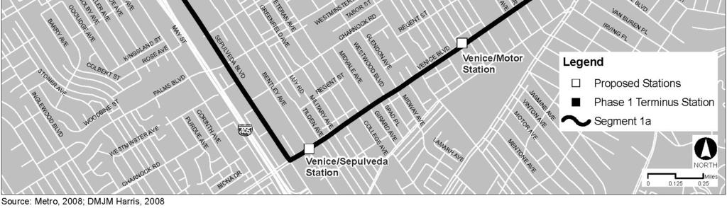
20 Figure Segment 1a: Venice/Sepulveda page 2-20
21 The alignment would continue on the aerial structure within the median of Venice Boulevard and cross Overland Avenue. The structure would be approximately 1,100 feet long and up to 30 feet high (to top of rail). The alignment would then transition to grade within the median of Venice Boulevard on a retained fill embankment. The embankment would be over 400 feet long and would begin just east of Glendon Avenue (Sta ) and terminate at approximately Westwood Boulevard (Sta ). The alignment would proceed at grade within the median of Venice Boulevard for approximately 1,100 feet and would then transition to an aerial structure over the intersection of Venice Boulevard and Sepulveda Boulevard. The embankment leading to the aerial structure would commence just west of Veteran Avenue (Sta ). It would be approximately 400 feet long and reach a height of up to 30 feet (to top of rail) before transitioning to the aerial structure just west of Military Avenue (Sta ). The aerial structure would continue in the median of Venice Boulevard before turning northwest into the center of Sepulveda Boulevard (Drawing T-010). An aerial station Venice/Sepulveda Station would be located on the aerial structure at approximately Bentley Avenue (Sta ) immediately before the alignment turns north onto Sepulveda Boulevard (at approximately Sta ). Street reconstruction would be required along the entire length of the alignment along Venice Boulevard. On Venice Boulevard, the existing number of traffic lanes and the existing Class II bike lanes would be retained but street parking would be eliminated over much of the alignment. 23 In addition, along Venice Boulevard, full and partial property acquisitions would be necessary to provide the necessary street width. Other partial acquisitions may be required to accommodate curb cuts to meet city standards, ADA, and other requirements. After turning northwest into the center of Sepulveda Boulevard, the alignment would continue in an aerial configuration for approximately 500 feet before transitioning to a retained fill embankment (Sta ). The total length of the aerial structure from west of Military Avenue on Venice Boulevard to the transition to retained fill embankment on Sepulveda Boulevard would be approximately 1,500 feet and would be up to 30 feet above grade (to top of rail). After the transition, the alignment would then continue on retained fill embankment for approximately 900 feet until approximately Charnock Road (South) (Sta ). At this point, due to the fact that Sepulveda Boulevard slopes rapidly upwards between Venice Boulevard and Charnock Road (South), the elevation of the street and the embankment would coincide and the alignment would briefly come to grade. Continuing north along the center of Sepulveda Boulevard, the alignment would again transition to a retained fill embankment just north of Charnock Road (South) (Sta ). After approximately 800 feet, this embankment would transition to an aerial structure just north of Westminster Avenue (Sta ). The aerial structure would continue within the center of Sepulveda Boulevard and would span the Sepulveda/National Boulevard intersection (Drawing T-009). The aerial structure would be approximately 4,400 feet long and would be up to 30 feet high (to top of rail). On the north side of National Boulevard the alignment would then transition to grade at approximately Sardis Avenue on a 300-foot-long retained fill embankment (Sta to Sta ). The alignment would continue at grade within the center of Sepulveda 23 Parking impacts are discussed in Section 3.2 (Transportation/Traffic). page 2-21
22 Boulevard until the intersection with the Exposition ROW (Sta ), a distance of approximately 2,600 feet. The proposed Sepulveda/National Station would be located just south of National Boulevard (Sta ) and would be an aerial station. Two single-track crossovers would be included on the aerial structure. One would be just north of the Sepulveda Channel (Station ) and the other just north of Queensland Street (Station ). Street reconstruction would also be required along the entire length of the alignment along Sepulveda Boulevard. The existing number of traffic lanes would be retained but the alignment would result in some restrictions on left-turn movements as the existing left-turn lanes would be used to accommodate the guideway within the center of the street and street parking would be eliminated over much of the alignment. There is an existing Class 3 bicycle route on Sepulveda Boulevard that would remain. Sepulveda Boulevard would need to be widened by approximately 30 feet at the intersection with the Exposition ROW to accommodate the at-grade LRT tracks and an additional southbound through lane. The street widening would extend from approximately 100 feet to the north of the Exposition ROW to Richland Avenue (south of the Exposition ROW). In addition, approximately 12 feet of Exposition Boulevard would be widened within the public right-of-way and Exposition ROW on the east side of Sepulveda Boulevard. Property acquisitions would also be required along Sepulveda Boulevard to accommodate the guideway and street improvements. Other partial acquisitions may be required to accommodate curb returns on both sides of the street to meet city standards, ADA, and other requirements. The alignment would turn to the west in an at-grade configuration at the intersection of Sepulveda Boulevard and the Exposition ROW (Sta ). Stations Segment 1a would have three stations as described below. All stations would be ADA compliant. All figures referred to in this section are found in Appendix F. Venice/Motor Station The proposed Venice/Motor Station would be located at grade within the median of Venice Boulevard immediately east of Motor Avenue (Drawing A ). The station would have two approximately 270-foot-long, 12-foot-wide side platforms. No station parking would be provided. Venice/Sepulveda Station This proposed station would be constructed as part of the aerial structure over the Venice/Sepulveda intersection (Drawing A ). The station would be located above the median of Venice Boulevard to the east of Sepulveda Boulevard. It would have an approximate 270-foot-long, 23-foot-wide center platform. A street level transit patron plaza would be provided below the station. Signalized pedestrian crosswalks would allow access from the plaza to the north and south sides of Venice Boulevard. No station parking would be provided. page 2-22
23 Sepulveda/National Station This proposed station would be constructed as part of the aerial structure along Sepulveda Boulevard. It would be located just south of National Boulevard above the center of Sepulveda Boulevard and would have an approximate 270-foot-long, 23-foot-wide center platform (Drawing A-1100). Pedestrian access would be provided from the southwest and southeast corners of the Sepulveda/National intersection. Pedestrians would utilize the crosswalk to access the median in the center of Sepulveda Boulevard and then travel down the center of the median to a point below the platform. Additional access would be provided from the west side of Sepulveda Boulevard to a point below the center of the platform via a mid-block crossing at Clover Avenue (west). Surface station parking for approximately 250 cars would be provided in the vicinity of the station. One parking location would encompass a portion of the block of currently occupied commercial uses at the northwest corner of the Sepulveda Boulevard/National Boulevard intersection. Vehicular access to this parking area would be from National Boulevard. A second parking location would be further south, at the corner of Sepulveda Boulevard and Clover Avenue, on two parcels currently occupied by a commercial use. Vehicular access to this parking area would be from Sepulveda Boulevard and Clover Avenue. All three parcels would be acquired to accommodate the guideway, stations, and associated street reconstruction Segment 2 (Sepulveda to Cloverfield) Exposition ROW from Sepulveda Boulevard to Olympic Boulevard (All LRT Alternatives) Alignment Drawings of the proposed LRT alignment and profile in this segment are provided in Appendix E (Plan and Profile), Drawing Nos. T-005, T-005A, T-004, and T-003. Segment 2 is also shown in Figure (Segment 2: Sepulveda to Cloverfield). From Sepulveda Boulevard, the alignment would continue west within the Exposition ROW in an at-grade configuration. The proposed Expo/Sepulveda Station would be located immediately west of Sepulveda Boulevard (Sta ). The alignment would transition to an aerial structure 600 feet west of Sepulveda, west of the proposed Expo/Sepulveda Station, and would cross under the elevated I-405 Freeway and over Sawtelle Boulevard in an aerial configuration (Drawing T-005). Alternately, if the LRT trackway is grade separated at Sepulveda Boulevard, the station would be aerial and the LRT trackway would continue on an aerial structure, underneath the I-405 Freeway. Refer to Appendix E (Plans and Profiles), Drawing No. T-005A. Sawtelle Boulevard would be reconstructed from approximately 400 feet south of Exposition Boulevard to approximately 200 feet north of Pico Boulevard (Appendix E, Drawing No. CP-100). At the LRT crossing, the reconstructed street would be at a lower elevation than the existing street to maintain sufficient vertical clearance under the trackway structure for vehicles traveling along Sawtelle Boulevard. To match the proposed elevations of Sawtelle Boulevard, portions of Exposition Boulevard would be reconstructed at a lower elevation than the existing pavement. These transition zones would be approximately 400 feet west and 300 feet east of Sawtelle Boulevard. page 2-23


24 Figure Segment 2: Sepulveda to Cloverfield page 2-24
25 Vehicular access would be maintained to the properties property at the southwest corner of Sawtelle Boulevard and Exposition Boulevard, however, the existing driveways and sidewalk would be reconstructed. At this corner, the sidewalk would be rebuilt at the existing elevation and a low retaining wall would be built between the sidewalk and the travel lanes. The sidewalk would be replaced on all four corners adjacent to the lowered street to provide pedestrian access at those corners. On the northwest and southeast corners, retaining walls would be built behind the sidewalk, on the property line. Grading (i.e., adjusting the ground level so that it is level or sloped to a specific incline) or a small retaining wall would be required on the northeast corner of Sawtelle Boulevard and Exposition Boulevard to meet existing grade. On the southwest corner, the entry to the multifamily housing structure would have to be modified to maintain access from the lowered street and reconstructed sidewalk to the building entrance the sidewalk would be along the curb and integrated into the adjacent building entrance. Pico Boulevard would be reconstructed from Gateway Boulevard to 400 feet east of Sawtelle Boulevard in order to match the new elevations on Sawtelle Boulevard as well as to construct a median island and to adjust the travel lanes to accommodate structural columns for the LRT (Drawing CP-200). The new back of sidewalk would be slightly lower than the existing elevations for up to 200 feet from Sawtelle Boulevard east and west on Pico Boulevard and 100 feet north of Pico Boulevard on Sawtelle Boulevard. Grading would be used where feasible to provide appropriate transitions. Access to some of the structures on the southwest corner of Pico Boulevard and Sawtelle Boulevard would be impacted by the change in elevation of Sawtelle Boulevard, necessitating reconstruction of some of the physical improvements on this site. Other locations may require curbs or short walls (height up to 18 inches) at the back of the sidewalk to maintain existing grades. Partial and full property acquisition would be required on Sawtelle Boulevard and Pico Boulevard as a result of the profile changes. Other partial acquisitions may be required to accommodate curb returns to meet city standards, ADA, and other requirements. After crossing Sawtelle Boulevard, the aerial structure would continue west within the Exposition ROW and then cross over the Pico/Exposition/Gateway Boulevards intersection. The total length of the aerial structure would be approximately 1,500 feet and, with the exception of the crossing under the elevated section of the I-405 Freeway, would be up to 30 feet high (to top of rail). At the crossing under the I-405, the structure would be approximately 15 feet above grade (to top of rail). The Exposition ROW width is generally 100 feet throughout this area. The roadway alignment on Pico Boulevard would be adjusted so that a structural column would be constructed in a new raised median island. This would be accomplished within the existing street right-of-way and would maintain the same number of traffic lanes. West of Pico Boulevard, the alignment would transition to grade via a retained fill embankment and have a barrier system, such as fencing or sound wall, parallel to and on both sides of the LRT trackway to prevent trespassing. The embankment would begin just west of Pico Boulevard (Sta ) and extend as far as Federal Avenue (Sta ), a length of 850 feet (Drawings T-004 and T-005). The alignment would cross Barrington Avenue at grade and would continue towards Bundy Drive. Immediately south of the Exposition ROW and east of Barrington Avenue, Exposition Boulevard would be reconfigured so that vehicle movements between Barrington Avenue and Exposition Boulevard would no longer be possible due to the proximity of the future crossing grates. A new traffic signal would be added for pedestrians to cross Barrington Avenue adjacent to the LRT trackway. Some street widening would also be required in the vicinity ofon Barrington Avenue and north of Pico Boulevard (south of the Exposition page 2-25
26 ROW) on the west side of the street. Adjacent to the LRT, portions of Exposition Boulevard would be reconstructed. As it approaches Bundy Drive, the alignment would transition to an aerial structure via a retained fill embankment. The embankment would begin at approximately Granville Avenue (Sta ) and extend as far as the east side of Bundy Drive (Sta ), a length of 950 feet. The proposed Expo/Bundy Station would be located immediately over the street (Sta ) or 300 feet to 400 feet to either the east or west of the street. The aerial structure would be approximately 400 feet long and up to 30 feet above grade (to top of rail). Street and curb reconstruction would occur within portions of Exposition Boulevard between Barrington and Centinela Avenues for the proposed station parking lot. Upon reaching the west side of Bundy Drive, the alignment would return to retained fill embankment between Bundy Drive and Centinela Avenue. A bridge structure, approximately 100 feet long, would span Centinela Avenue. West of Centinela Avenue, the alignment would transition to grade within the Exposition ROW on a retained fill embankment approximately feet west of Bundy DriveCentinela Avenue (Sta to ). This grade separation at Centinela Avenue was added to the project in the FEIR after further analysis and consultation with LADOT. Continuing west, the alignment would continue at grade within the Exposition ROW for a distance of approximately 4, feet and would cross Centinela Avenue, Stewart Street and 26th Street in an at-grade configuration with crossing gates (Drawings T-004 and T-003). Portions of Stewart and 26th Streets would be reconstructed adjacent to the crossing and would have warning devices that would include audible warnings, signs and flashing lights, and gates to prevent entry into the trackway when trains pass. Also, a barrier system, such as fencing or sound wall, would be included parallel to and on both sides of the LRT trackway to prevent trespassing. A maintenance facility would be built between Centinela Avenue and Stewart Street, to the south of the Exposition ROW. This facility is described below at the end of Section [Other Related Facilities]). Approximately 10 feet of street widening would be required along Centinela Avenue between the Exposition ROW and Olympic Boulevard to accommodate an additional northbound lane of traffic. This would require a partial property acquisition on the west side of the street between the Exposition ROW and Olympic Boulevard. Exposition Boulevard would be reconstructed for approximately 100 feet east of Centinela. A signalized crossing would be provided at Exposition Boulevard on Centinela Avenue to facilitate safe pedestrian crossings. Street and curb reconstruction would occur in this area, including reconstruction of portions of Exposition Boulevard between Centinela Avenue and Barrington Avenue. Some minor street reconfiguration would be required at Stewart Street (approximately 85 square feet) to add a southbound through lane. Existing on-street parking would need to be eliminated on the east and west sides of the street for one block south of the Exposition ROW. In association with these modifications, the median on Olympic Boulevard would need to be reconstructed to allow for the addition of an eastbound right-turn lane and a westbound left-turn lane onto Stewart Street. The existing coral trees are not impacted by the turn lane changes and would be protected in place. These modifications would all occur within the existing street rightof-way. In addition, the lead tracks to the maintenance facility would be located within the page 2-26
27 Exposition ROW west of Stewart Street, resulting in three sets of tracks crossing Stewart Street at grade. The Exposition ROW decreases to a width of approximately 50 feet west of Stewart Street and further decreases to a minimum of approximately 30 feet just east of 26th Street. The proposed Olympic/26th Street Station would be located at grade immediately east of 26th Street (Sta ). As such, a partial acquisition of City of Santa Monica-owned property would be required on the south side of the Exposition ROW to accommodate the LRT tracks and proposed station. Minor narrowing of the median islands on Olympic Boulevard would be required to allow change to the intersection lane configuration. The existing coral trees are not impacted by the turn lane changes and would be protected in place. Reconstruction of portions of eastbound Olympic Boulevard would be required in this area. Immediately west of 26th Street, the Exposition ROW increases to approximately 65 feet in width and the alignment transitions to an aerial structure over Cloverfield Boulevard and Olympic Boulevard, with retained fill embankments leading to and from the aerial structure. The embankment on the east side of Cloverfield Boulevard would be approximately 350 feet long (Sta to ) and would gradually reach a height of up to 30 feet (to top of rail) at the point where it transitions to the aerial structure. The aerial structure over Cloverfield Boulevard would be approximately 1,000 feet in length and would be up to 30 feet high (to top of rail). Stations Segment 2 would have three proposed stations as described below. Stations would be ADA compliant. All figures referred to in this section are found in Appendix F. Expo/Sepulveda Station The proposed Expo/Sepulveda Station would be located within the Exposition ROW just west of Sepulveda Boulevard (Drawing A-700). The station would be at grade and would have two approximately 270-foot-long, 12-foot-wide side platforms. Access would be from Sepulveda and Exposition Boulevards. A parking structure would be constructed on the site of the existing surface parking lot of the City of LADOT property to the south of the station. The structure would have two decks above the existing surface parking. Each of the two decks would have approximately 130 spaces. The ground level would continue to accommodate existing LADOT parking requirements, while the other two levels would be for station parking. Vehicular access to this facility would be from Exposition Boulevard. Alternately, with the grade separated design option at Sepulveda Boulevard, the station platform would be aerial, with a ground-level entry area and vertical circulation elements. Expo/Bundy Station This proposed station would be constructed as part of the aerial structure over Bundy Drive (Drawing A-600). The station would have an approximate 270-foot-long, 23-foot-wide center platform and would be located either immediately over the street or a short distance to either the east or the west of the street. Access to the platform would be by stairs and elevators at one or both ends of the platform. page 2-27
28 Up to 250 surface parking spaces would be built within the Exposition ROW between Barrington Avenue and Centinela Avenue. Vehicular access to these spaces would be from Exposition Boulevard. Olympic/26 th Street Station The proposed Olympic/26th Street Station would be located east of 26th Street in Santa Monica (Drawing A-500). The at-grade station would lie partially within the Exposition ROW, which narrows to a minimum of approximately 30 feet at this location, and partially within City of Santa Monica-owned property to the south of the Exposition ROW. It would be an at-grade station and would have an approximate 270-foot-long, 16-foot-wide center platform. No station parking would be provided Segment 3 (Olympic) Olympic Boulevard from Exposition ROW to Santa Monica Terminus (LRT Alternatives 1 and 3) Alignment Drawings of the proposed LRT alignment and profile in this segment option, which would connect to Segment 2, are provided in Appendix E, Drawing Nos. T-003, T-002, and T-001. Segment 3 is also shown in Figure (Segment 3: Olympic). As shown in Drawing T-003, this segment would begin with an aerial structure over Cloverfield Boulevard which would enter the median of Olympic Boulevard. The aerial structure would be approximately 1,000 feet long and up to 30 feet high (to top of rail). As shown on Drawing T-002, Tthe alignment would transition to grade within the median of Olympic Boulevard on a 275-foot-long retained fill embankment that would terminate at approximately 21st Street (Sta ). The alignment would continue at grade within the median of Olympic Boulevard until approximately Euclid Street (Sta ), a distance of approximately 3,100 feet, and would cross the 20th Street, 17th Street, and 14th Street intersections at grade in street running mode. 24 The proposed Olympic/17th Street Station would have split platforms and would be located within the median of Olympic Boulevard on the east and west sides of 17th Street. A double-track crossover 25 would be located at approximately 19th Street (Station ). Street reconstruction would be required along Olympic Boulevard between 20th Street and 14th Street to accommodate the LRT alignment and station. Some partial property acquisitions may be required to accommodate curb reconstruction to meet city standards, ADA, and other requirements. On-street parking would be removed between 22nd Street and 11 th Street. Existing coral trees in the median of Olympic Blvd would be removed for the construction of the LRT trackway and station. 24 Street-running mode is a mode of operation where train movement is manually controlled by the Train Operator in accordance with traffick signals and posted speed limits. Maximum allowable speed is 35 mph. Street-running territory refers to segments of mainline tracks where trains travel adjacent to vehicular traffic and are separated only by a median or barrier, per CPUC approval. 25 A crossover is a connection between two adjacent tracks, allowing a train on one track to cross over to the other. When two crossovers are present in opposite directions, one after the other, the configuration is called a double crossover. page 2-28


29 Figure Segment 3: Olympic page 2-29
30 Immediately west of Euclid Street the alignment would transition to an aerial structure by means of a retained fill embankment. The embankment would be approximately 700 feet long extending from approximately Euclid Street (Sta ) to just east of 11th Street (Sta ) and would gradually reach a height of up to 30 feet (to top of rail) at the point where it would transition to an aerial structure (Sta ). Continuing to the west, the alignment would be on aerial structure either above the median of Olympic Boulevard or adjacent to properties on the south side of Olympic Boulevard or adjacent to or above the embankment of the I-10 Freeway. The aerial structure would cross over the 11th Street, 10th Street, 9th Street, Lincoln Street, 7th Street and 5th Street intersections before turning north and terminating at the site of the proposed Colorado/4th Street Station at the corner of 4th Street and Colorado Avenue (Sta ). A double-track crossover would be provided on the aerial structure at approximately 6th Street (Station ). Street reconstruction would be required on Olympic Boulevard between 7th Street (Sta ) and 5th Street (Sta ) to allow for column placement. Property acquisition for the proposed terminus station would be required. The total length of the aerial structure from the east side of 11th Street to the terminus at 4th Street and Colorado Avenue would be approximately 3,300 feet and would be up to 35 feet above grade (to top of rail). Stations Segment 3 would have two stations as described below. Stations would be ADA compliant. All figures referred to in this section are found in Appendix F. Olympic/17 th Street Station For the Segment 3 option, the proposed Olympic/17th Street Station would be a split-platform station located at grade within the median of Olympic Boulevard on the east and west sides of 17th Street (Drawing A-300). Each platform would be at least 270 feet long and 12 feet wide. No station parking would be provided. Colorado/4 th Street Station The proposed Colorado/4th Street Station would be the western terminus of the project (Drawing A-100). It would be located on the site of an existing commercial block bounded by 4th Street, 5th Street, and Colorado Avenue. A significant portion of the station site is owned by the City of Santa Monica and was acquired for transit-related use. The station would be aerial and would have a two-platform/three-track configuration. Each platform would be at least 270 feet long and 16 feet wide. The station would be 35 feet above the grade of the Colorado Avenue/4th Street intersection and would be approximately 22 feet lower than the roof of the adjacent Macy s building located at the northwest corner of the intersection. Access to the platforms would be from the street level via stairs and elevators. After further consultation with the City of Santa Monica, no parking would be built at the Colorado/4 th Street Station. Although, the approximate 215 parking space demand at this station would be provided through the City of Santa Monica s Downtown Parking Program. Transit patrons would use pubic designated parking spaces in nearby public parking facilities in downtown Santa Monica.Approximately 250 surface parking spaces would be located on the same block, adjacent to the station platforms. Vehicular access to the parking area would be from 5 th Street. page 2-30
31 2.4.5 Segment 3a (Colorado) Colorado Avenue from Exposition ROW to Santa Monica Terminus (LRT Alternatives 2 and 4) Alignment Drawings of the proposed LRT alignment and profile in this segment option, which would connect with Segment 2, are provided in Appendix E, Drawing Nos. T-013, T-013, and T-014. Segment 3a is also shown in Figure (Segment 3a: Colorado). As shown on Drawing T-014, this segment would begin with an aerial structure over Cloverfield and Olympic Boulevards, and would continue westerly within the Exposition ROW to the west of Olympic Boulevard. The aerial structure would be approximately 800 feet long and as high as 30 feet (to top of rail) above grade. The alignment would transition to grade within the Exposition ROW on a retained fill embankment. The embankment would begin immediately west of Olympic Boulevard (Sta ) and end just east of 20th Street (Sta ). The alignment would continue within the Exposition ROW from 20th Street until west of 19th Street in an at-grade configuration with crossing gates, a distance of approximately 600 feet.warning devices that would include audible warnings, flashing lights, and gates to prevent entry into the trackway when trains pass. Also, a barrier system, such as fencing or sound wall, would be included parallel to and on both sides of the LRT trackway to prevent trespassing. A double-crossover would be required between 19 th and 20 th Streets. At this point the alignment would turn into the center of Colorado Avenue via an at-grade crossing at 17 th Street and operate in street running mode. The proposed Colorado/17 th Street Station would be located within the center of Colorado Avenue just west of 17 th Street (Sta ). From the proposed Colorado/17th Street Station, the alignment would continue at grade along the center of Colorado Avenue via embedded track to the terminus, a distance of approximately 5,500 feet, and would include at-grade crossings at 17th Street, 14th Street, 11th Street, Lincoln Boulevard, 7th Street, 6th Street, and 5th Street. Each of these crossings would be signalized for vehicular/pedestrian crossing. Vehicular left turns would no longer be permitted from Colorado Avenue to 16th, 15th, 14th, 12th, 11th, 10th, 9th, 7th, 6th, 5th Streets, Lincoln Boulevard and Euclid Street. After further consultation with the City of Santa Monica and Big Blue Bus, it was determined that buses would be permitted to turn left from westbound Colorado Avenue to the Big Blue Bus Maintenance Facility at 6 th Street. This would require special signaling. Left turns from Colorado Avenue to 17th and 4th Streets would be permitted. Left turns from 17th, 14th, 11th, 7th, 6th, 5th, and 4th Streets and Lincoln Boulevard to Colorado Avenue will also be permitted. The Colorado/4th Street Station terminus would be on the existing commercial block bounded by 4th Street, 5th Street, and Colorado Avenue, which is the same location as the Colorado/4th Street Station terminus described for the Segment 3 option. Street reconstruction work and lane reconfiguration would be required along Colorado Avenue between approximately 18th Street and the terminus to accommodate the LRT alignment and 17th Street Station. Several commercial/industrial parcels would need to be acquired between 16th Street and 18th Street on the south side of Colorado Avenue in order to accommodate the transition from the Exposition ROW into Colorado Avenue and to accommodate an eastbound right-turn lane at Lincoln Boulevard. One lane of traffic would be retained in each direction along Colorado Avenue and on-street parking would be retained along the north side of the street only. In addition, some partial parcel acquisitions may be required to accommodate curb return page 2-31

32 Figure Segment 3a: Colorado page 2-32
3.14 Parks and Community Facilities
 3.14 Parks and Community Facilities 3.14.1 Introduction This section identifies the park and community facility resources in the study area and examines the potential impacts that the proposed Expo Phase
Exposition Corridor Transit Project
 Exposition Corridor Transit Project Phase 2 Environmental Planning Community Meeting June 9, 2008 Exposition Corridor Transit Project Phase 2 AGENDA Remaining Grade Crossing Recommendations June 9, 2008
Project Scoping Report Appendix B Project Web Site. APPENDIX B Project Web Site
 Project Scoping Report Appendix B Project Web Site APPENDIX B Project Web Site WESTSIDE EXTENSION TRANSIT CORRIDOR STUDY February 4, 2008 News and Info of 1 http://metro.net/projects_programs/westside/news_info.htm#topofpage
3.11 Land Use/Planning
 3.11 Land Use/Planning 3.11.1 Introduction This section identifies existing and future land uses as defined by the land use plans of the local jurisdictions. The section also identifies the existing land
2.4 Build Alternatives
 Table 2-1. Future Transit Network Changes between No Build and TSM Alternatives Operator Route Group No. Route ID and Description Peak Headway (min) No Build Off-peak Headway (min) Peak Headway (min) TSM
Executive Summary. Draft Environmental Impact Statement/Environmental Impact Report ES-1
 Executive Summary Introduction The Eastside Transit Corridor Phase 2 Project is a vital public transit infrastructure investment that would provide a transit connection to the existing Metro Gold Line
Preliminary Definition of Alternatives. 3.0 Preliminary Definition of Alternatives
 3.0 What preliminary alternatives are being evaluated? The alternatives for the East San Fernando Valley Transit Corridor project that were considered for screening include the No Build Alternative, Transportation
EXECUTIVE SUMMARY. Introduction. Project Purpose. Executive Summary
 EXECUTIVE SUMMARY Introduction The Exposition Metro Line Construction Authority (Expo Authority) has prepared this Draft Final Environmental Report (DFEIR) in order to extend high -capacity, high -frequency
4.1 Traffic, Circulation, and Parking
 4.1 Traffic, This section describes the existing transportation and parking conditions within and adjacent to the project area. A traffic report describing the potential impacts of the proposed project
Expo Light Rail Line. Expo Line Project Westside/Central Metro Service Council November 2014
 Expo Line Project Westside/Central Metro Service Council November 2014 2 Expo Line Project Description Phase 2 Expo Line from Culver City to Santa Monica: 6.6 mile corridor 7 new Stations 64,000 Daily
IV. ENVIRONMENTAL IMPACT ANALYSIS J. TRANSPORTATION AND TRAFFIC
 IV. ENVIRONMENTAL IMPACT ANALYSIS J. TRANSPORTATION AND TRAFFIC This Section summarizes the information provided in the Traffic Study for the Santa Monica College Bundy Campus Master Plan (Traffic Study),
Sepulveda Pass Corridor Systems Planning Study Update
 Los Angeles County Metropolitan Transportation Authority Sepulveda Pass Corridor Systems Planning Study Update June 20, 2012 Measure R Transit Corridors One of 12 Measure R Transit Corridors approved by
Countdown to the Closure Extended 53-Hour Closure of I-405 Freeway Between U.S. 101 and I-10 Planned in Mid-July for Mulholland Bridge Demolition
 Countdown to the Closure Extended 3-Hour Closure of I-40 Freeway Between U.S. 0 and I-0 Planned in Mid-July for Mulholland Bridge Demolition Work Los Angeles, Calif. Plan Ahead, Avoid The Area, Or Stay
IMPROVEMENT CONCEPTS
 IMPROVEMENT CONCEPTS for the South Novato Transit Hub Study Prepared by: January 11, 2010 DKS Associates With Wilbur Smith Associates IMPROVEMENT CONCEPTS Chapter 1: Introduction 1. INTRODUCTION The strategic
3. PRELIMINARY DEFINITION OF ALTERNATIVES
 3. PRELIMINARY DEFINITION OF ALTERNATIVES The purpose of the Preliminary Definition of Alternatives is to introduce the alternatives, including modes and off- and on-airport routes that will be carried
Study Area, Related Projects and Travel Markets
 Study Area, Related Projects and Travel Markets Study area and related projects Travel between Valley and Westside North San Fernando Valley BRT (Alignment TBD) East San Fernando Valley Transit Corridor
Mobility Corridor Updates. Transit & Active Transportation Projects
 Mobility Corridor Updates Transit & Active Transportation Projects Manjeet Ranu, SEO East San Fernando Valley Transit Corridor Metro Board LPA selection: June 2018 Recently awarded $200 million in Senate
Mobility Corridor Updates. Transit & Active Transportation Projects
 Mobility Corridor Updates Transit & Active Transportation Projects Laura Cornejo, DEO Regional Planner Regional Operator Metro is LA County s Regional Builder/Funder Rail Bus Service (Metro/Muni/Local)
I-405 Sepulveda Pass Improvements Project
 I-405 Sepulveda Pass Improvements Project Community Meeting November 15, 2012 1 Wilshire Segment Overview of Wilshire Segment There are a total of 23 bridges being constructed on this project; almost half
Develop ground transportation improvements to make the Airport a multi-modal regional
 Project Overview TRANSPORTATION IMPROVEMENTS WHAT ARE THE PROJECT GOALS? Transportation transportation hub. Develop ground transportation improvements to make the Airport a multi-modal regional Land Use
East San Fernando Valley Transit Corridor. TAC Briefing December 4, 2013
 East San Fernando Valley Transit Corridor TAC Briefing December 4, 2013 Overview Measure R Project Long Range Transportation Plan Reserves $170.1 Million 2018 Revenue Operations Date Coordination with
Crenshaw-Prairie Transit Corridor Study Public Meetings
 Crenshaw-Prairie Transit Corridor Study Public Meetings Darby Park: Wednesday, February 20, 2008 6:30 8:00 PM US Bank Community Room: Thursday, February 21, 2008 6:30 8:00 PM Nate Holden Performing Arts
Expo Light Rail Line. Expo Line Community Meeting Quarterly Phase 2 Construction Update Los Angeles April 2014
 Expo Line Community Meeting Quarterly Phase 2 Construction Update Los Angeles April 2014 Meeting Agenda Phase 2 Construction Update Meeting Meeting Purpose and Format Construction Update Expo Bikeway Update
IV. ENVIRONMENTAL IMPACT ANALYSIS B. TRAFFIC AND CIRCULATION
 IV. ENVIRONMENTAL IMPACT ANALYSIS B. TRAFFIC AND CIRCULATION 1. INTRODUCTION This section is based on the technical report, Traffic Study for 10131 Constellation Boulevard Residential Project, prepared
Chapter 2 Alternatives Considered
 Beverly Center Area Station Figure 2-54. Santa Monica/San Vicente Station This station would be under San Vicente Boulevard, extending from just south of Gracie Allen Drive to south of Third Street (Figure
Chapter 9 Recommended Locally Preferred Alternative and Alternatives for Evaluation in Draft SEIS/SEIR
 Chapter 9 Recommended Locally Preferred Alternative and Alternatives for Evaluation in Draft SEIS/SEIR 9.0 RECOMMENDED LOCALLY PREFERRED ALTERNATIVE AND ALTERNATIVES FOR EVALUATION IN DRAFT SEIS/SEIR
Sepulveda Pass Corridor Systems Planning Study
 Los Angeles County Metropolitan Transportation Authority Sepulveda Pass Corridor Systems Planning Study Streets and Freeways Subcommittee January 17, 2013 1 Sepulveda Pass Study Corridor Extends for 30
REGIONAL TRANSPORTATION SETTING
 CIRCULATION ELEMENT WHITE PAPER NO. 1 REGIONAL TRANSPORTATION SETTING INTRODUCTION According to the Southern California Association of Governments (SCAG), by 2030 the six- County region will be home to
IV. ENVIRONMENTAL IMPACT ANALYSIS L. TRAFFIC, TRANSPORTATION, AND PARKING
 IV. NVIRONMNTAL IMPACT ANALYSIS L. TRAFFIC, TRANSPORTATION, AND PARKING INTRODUCTION The following summarizes the information provided in the traffic report prepared by Hirsch/Green Transportation Consulting,
WESTSIDE SUBWAY EXTENSION. Traffic Analysis Impact Report
 Traffic Analysis Impact Report August 2010 Table of Contents Table of Contents 1.0 INTRODUCTION/SUMMARY...1-1 1.1 Existing (Year 2006) Setting... 1-1 1.2 Future (Year 2035) Setting... 1-2 2.0 PROJECT
Note: The October 2007 version of this report has been updated in this December 2008 report to present costs in year 2007 dollars.
 Sound Transit Phase 2 South Corridor LRT Design Report: SR 99 and I-5 Alignment Scenarios (S 200 th Street to Tacoma Dome Station) Tacoma Link Extension to West Tacoma Prepared for: Sound Transit Prepared
Community Meetings June 2018
 Community Meetings June 2018 1 Welcome and Agenda Thank you for joining us! 6:00 pm Open House 6:30 pm Welcome & Presentation 7:00 pm Q&A 7:15 pm Open House Resumes 8:00 pm Meeting Concludes 2 Purpose
Welcome and Agenda. Thank you for joining us! 6:00 pm Open House. 6:30 pm Welcome & Presentation. 7:00 pm Q&A. 7:15 pm Open House Resumes
 1 Welcome and Agenda Thank you for joining us! 6:00 pm Open House 6:30 pm Welcome & Presentation 7:00 pm Q&A 7:15 pm Open House Resumes 8:00 pm Meeting Concludes 2 Purpose of this Meeting Introduce project
3.0 TRANSPORTATION ISSUES AND ANALYSIS
 3.0 TRANSPORTATION ISSUES AND ANALYSIS 3.1 Transit Analysis The following sections address the anticipated transit service levels under each of the alternatives considered in the detailed screening as
IV. ENVIRONMENTAL IMPACT ANALYSIS N. TRANSPORTATION AND TRAFFIC
 IV. ENVIRONMENTAL IMPACT ANALYSIS N. TRANSPORTATION AND TRAFFIC The following section summarizes the information provided in the traffic report entitled Traffic Impact Analysis for a Proposed Residential
3.17 Energy Resources
 3.17 Energy Resources 3.17.1 Introduction This section characterizes energy resources, usage associated with the proposed Expo Phase 2 project, and the net energy demand associated with changes to the
Expo Light Rail Line. Expo Line Community Meeting Quarterly Phase 2 Construction Update Los Angeles February 2015
 Expo Line Community Meeting Quarterly Phase 2 Construction Update Los Angeles February 2015 Meeting Agenda Phase 2 Construction Update Meeting Meeting Purpose and Format Construction Update Expo Bikeway
LOS ANGELES COUNTY METROPOLITAN TRANSPORTATION AUTHORITY (LACMTA) AND FEDERAL TRANSIT ADMINISTRATION (FTA)
 AND FEDERAL TRANSIT ADMINISTRATION (FTA)") LOS ANGELES COUNTY METROPOLITAN TRANSPORTATION AUTHORITY (LACMTA) AND FEDERAL TRANSIT ADMINISTRATION (FTA) NOTICE OF PREPARATION (NOP)/NOTICE OF INTENT (NOI) OF AN ENVIRONMENTAL IMPACT STATEMENT (EIS)/ENVIRONMENTAL
LOS ANGELES COUNTY METROPOLITAN TRANSPORTATION AUTHORITY (LACMTA) AND FEDERAL TRANSIT ADMINISTRATION (FTA) NOTICE OF PREPARATION (NOP)/NOTICE OF INTENT (NOI) OF AN ENVIRONMENTAL IMPACT STATEMENT (EIS)/ENVIRONMENTAL
engineering phase and during the procurement of design build contracts.
 CONSIDERATION OF ALTERNATIVES Below-grade trench alignment along Aviation Boulevard, adjacent to LAX south runways. miles. MOS-Century would extend from the Metro Exposition Line to the Aviation/ Century
Project Scoping Open House Welcome
 Scoping Meeting Project Scoping Open House Welcome Alternatives Analysis (AA) and Draft Environmental Impact Statement/Draft Environmental Impact Report (DEIS/DEIR) Project Purpose Purpose of the Project
TRANSPORTATION STUDY FOR THE 8899 BEVERLY BOULEVARD PROJECT
 DRAFT TRANSPORTATION STUDY FOR THE 8899 BEVERLY BOULEVARD PROJECT WEST HOLLYWOOD, CALIFORNIA NOVEMBER 2013 PREPARED FOR BEVERLY BOULEVARD ASSOCIATION PREPARED BY DRAFT TRANSPORTATION STUDY FOR THE 8899
FINAL. Sound Transit Long-Range Plan Update. Issue Paper S.1: Tacoma Link Integration with Central Link. Prepared for: Sound Transit
 Sound Transit Long-Range Plan Update Issue Paper S.1: Tacoma Link Integration with Central Link Prepared for: Sound Transit Prepared by: Quade & Douglas, Inc. FINAL March 2005 Foreword This issue paper
Westside Subway Extension Draft Environmental Impact Statement/ Environmental Impact Report
 Los Angeles County Metropolitan Transportation Authority Westside Subway Extension Draft Environmental Impact Statement/ Environmental Impact Report > Executive Summary September 2010 The U.S. Department
Unified Corridor Investment Study DRAFT Step 2 Scenario Analysis Report
 Unified Corridor Investment Study DRAFT Step 2 Scenario Analysis Report REVISIONS 1. Table 39: New Public Investments for Operation and Maintenance Costs 2. Appendix A-10: Passenger Rail Service - Operations
King County Metro. Columbia Street Transit Priority Improvements Alternative Analysis. Downtown Southend Transit Study. May 2014.
 King County Metro Columbia Street Transit Priority Improvements Alternative Analysis Downtown Southend Transit Study May 2014 Parametrix Table of Contents Introduction... 1 Methodology... 1 Study Area...
2.0 Development Driveways. Movin Out June 2017
 Movin Out June 2017 1.0 Introduction The proposed Movin Out development is a mixed use development in the northeast quadrant of the intersection of West Broadway and Fayette Avenue in the City of Madison.
Pacific Electric Right-of-Way / West Santa Ana Branch Corridor Alternatives Analysis
 Pacific Electric Right-of-Way / West Santa Ana Branch Corridor Alternatives Analysis Transit Coalition September 26, 2012 2 Study Area Pacific Electric Rightof-Way/West Santa Ana Branch (PEROW/ WSAB) extends
BROWARD BOULEVARD CORRIDOR TRANSIT STUDY
 BROWARD BOULEVARD CORRIDOR TRANSIT STUDY FM # 42802411201 EXECUTIVE SUMMARY July 2012 GOBROWARD Broward Boulevard Corridor Transit Study FM # 42802411201 Executive Summary Prepared For: Ms. Khalilah Ffrench,
2. Valley Circle Boulevard/Andora Avenue/Baden Avenue and Lassen Street
 IV.J TRANSPORTATION 1. INTRODUCTION This section presents an overview of the existing traffic and circulation system in and surrounding the project site. This section also discusses the potential impacts
Sherman Oaks Community Traffic Plan
 Sherman Oaks is a community that is geographically bound by the Santa Monica mountains on its southern boundary, and the ever-expanding San Fernando Valley on its western, northern, and eastern boundaries.
BERKELEY DOWNTOWN AREA PLAN PROGRAM ENVIRONMENTAL IMPACT REPORT TRAFFIC IMPACT ANALYSIS
 BERKELEY DOWNTOWN AREA PLAN PROGRAM ENVIRONMENTAL IMPACT REPORT TRAFFIC IMPACT ANALYSIS Prepared for: City of Berkeley Prepared by: REVISED JANUARY 9, 2009 Berkeley Downtown Area Plan Program EIR Traffic
The range of alternatives has been reviewed with the RTAC Subgroup and the preliminary analysis is proceeding on the following HCT alternatives:
 Attachment 2 Boise Treasure Valley Phase 1 Alternatives Analysis August 14, 2009 Introduction The Treasure Valley High Capacity Transit Priority Corridor Phase 1 Alternatives Analysis is being prepared
Traffic Engineering Study
 Traffic Engineering Study Bellaire Boulevard Prepared For: International Management District Technical Services, Inc. Texas Registered Engineering Firm F-3580 November 2009 Executive Summary has been requested
III. CORRECTIONS AND ADDITIONS TO THE DRAFT EIR
 III. CORRECTIONS AND ADDITIONS TO THE DRAT EIR DRAT EIR I. INTRODUCTION/SUMMARY In response to Comment No. 2.1 on the Draft EIR, the following mitigation measure is added to Table I- 1, Summary of Environmental
Section 5.8 Transportation and Traffic
 Section 5.8 Transportation and Traffic 5.8 TRANSPORTATION AND TRAFFIC Generous This Section is based on the Topgolf Specific Plan Traffic Impact Analysis (RK Engineering Group, Inc., October 31, 2016);
Madison BRT Transit Corridor Study Proposed BRT Operations Plans
 Madison BRT Transit Corridor Study Proposed BRT Operations Plans This paper presents a description of the proposed BRT operations plan for use in the Madison BRT Transit Corridor Study. The objective is
Operating & Maintenance Cost Results Report
 Operating & Maintenance Cost Results Report Prepared for: Hennepin County Regional Railroad Authority Prepared by: Connetics Transportation Group Under Contract To: Kimley-Horn and Associates FINAL June
Community Meetings Welcome
 Community Meetings Welcome Thank you for joining us! Community Meetings Agenda 6pm Open House 6:30pm Welcome & Presentation 7pm Q&A 7:15pm Open House Resumes 8pm Meeting Concludes Community Meetings Agenda
Green Line Extension to Torrance Supplemental Alternatives Analysis. 2. Purpose and Need 2. PURPOSE AND NEED
 2. PURPOSE AND NEED This chapter characterizes the transportation and mobility problems and identifies project goals, objectives, and evaluation criteria to improve these problems for the Green Line Extension
Alternatives Analysis Findings Report
 6.0 This chapter presents estimates of the potential capital, operations and maintenance costs associated with the alternatives carried forward for detailed evaluation. The methodology used to develop
3.15 SAFETY AND SECURITY
 3.15 SAFETY AND SECURITY Introduction This section describes the environmental setting and potential effects of the alternatives analyzed in this EIR with regard to safety and security in the SantaClara-Alum
Sound Transit East Link: Bus/LRT System Integration Study
 Sound Transit East Link: Bus/LRT System Integration Study Prepared For: Sound Transit King County Metro Mercer Island WSDOT Prepared By: CH2M HILL July, 2014 1 SOUND TRANSIT EAST LINK: BUS/LRT SYSTEMES
Welcome. Please Sign In
 Welcome South Bay Bus Rapid Transit (BRT) Draft Environmental Impact Report (DEIR) Public Meeting Please Sign In Please comment in any of the following manners: 1. Submit a comment form 2. Provide verbal
ANDERSON PROPERTY SITE ANALYSIS
 ANDERSON PROPERTY SITE ANALYSIS Introduction The Montgomery County Department of Transportation (MCDOT) initiated a feasibility study in the fall of 2012 to evaluate the need for transit service expansion
TRANSPORTATION 1. INTRODUCTION 2. METHODOLOGY
 IV.K TRANSPORTATION 1. INTRODUCTION This section provides an analysis of potential impacts associated with traffic, parking, and access. The analysis provides an overview of existing traffic conditions
Troost Corridor Transit Study
 Troost Corridor Transit Study May 23, 2007 Kansas City Area Transportation Authority Agenda Welcome Troost Corridor Planning Study Public participation What is MAX? Survey of Troost Riders Proposed Transit
Brigham City 1200 West Box Elder Creek Bridge - Widening Project Type Reconstruction
 Brigham City 1200 West Box Elder Creek Bridge - Widening Project Type Reconstruction 550 North to 650 North $ 1,750,000 $ 1,582,113 To widen an existing bridge on 1200 West over Box Elder Creek that will
APPENDIX F-IV.K Updated Transportation Impact Analysis (June 2010)
") APPENDIX F-IV.K Updated Transportation Impact Analysis (June 2010) TRANSPORTATION IMPACT ANALYSIS FOR THE LOYOLA MARYMOUNT UNIVERSITY MASTER PLAN PROJECT JUNE 2010 PREPARED FOR AECOM Design PREPARED BY
APPENDIX F-IV.K Updated Transportation Impact Analysis (June 2010) TRANSPORTATION IMPACT ANALYSIS FOR THE LOYOLA MARYMOUNT UNIVERSITY MASTER PLAN PROJECT JUNE 2010 PREPARED FOR AECOM Design PREPARED BY
STH 60 Northern Reliever Route Feasibility Study Report
 #233087 v3 STH 60 Northern Reliever Route Feasibility Study Report Washington County Public Works Committee Meeting September 28, 2016 1 STH 60 Northern Reliever Route Feasibility Study Hartford Area Development
East San Fernando Valley Transit Corridor. Information Session, October 10, 2017
 East San Fernando Valley Transit Corridor Information Session, October 10, 2017 1 Welcome and Meeting Purpose Introductions Metro Transit Corridors Planning Metro Real Estate Metro Community Relations
We re using a giant machine to dig tunnels for trains.
 metro.net/crenshaw We re using a giant machine to dig tunnels for trains. crenshaw/lax transit project Tunnel Boring Machine Fun Facts #CrenshawTBM What is a Tunnel Boring Machine (TBM)? A TBM is like
Federal Way Link Extension
 Federal Way Link Extension Draft EIS Summary Route & station alternatives and impacts Link Light Rail System Map Lynnwood Mountlake Terrace Lynnwood Link Extension Shoreline 14th Northgate 40 Northgate
IV. ENVIRONMENTAL IMPACT ANALYSIS M. TRANSPORTATION AND TRAFFIC
 IV. ENVIRONMENTAL IMPACT ANALYSIS M. TRANSPORTATION AND TRAFFIC INTRODUCTION This section of the (Draft EIR) addresses the subject of traffic and transportation with respect to the proposed (Project or
RICHMOND OAKS HEALTH CENTRE 6265 PERTH STREET OTTAWA, ONTARIO TRANSPORTATION BRIEF. Prepared for: Guycoki (Eastern) Limited.
 Limited.") RICHMOND OAKS HEALTH CENTRE 6265 PERTH STREET OTTAWA, ONTARIO TRANSPORTATION BRIEF Prepared for: Guycoki (Eastern) Limited June 16, 2016 116-638 Brief_1.doc D. J. Halpenny & Associates Ltd. Consulting
RICHMOND OAKS HEALTH CENTRE 6265 PERTH STREET OTTAWA, ONTARIO TRANSPORTATION BRIEF Prepared for: Guycoki (Eastern) Limited June 16, 2016 116-638 Brief_1.doc D. J. Halpenny & Associates Ltd. Consulting
CITY OF BEVERLY HILLS STAFF REPORT
 Meeting Date: July 7, 2011 To: From: Subject: CITY OF BEVERLY HILLS STAFF REPORT Honorable Mayor & City Council Pamela Mottice Muller, Director of Emergency Management 405 Closure Attachments: 1. 1-405
Draft Supplemental Transportation Analysis Santa Clara - Alum Rock Transit Corridor APPENDIX A TRAFFIX Level of Service Calculation Sheets 2012 BRT 20
 Draft Supplemental Transportation Analysis Santa Clara - Alum Rock Transit Corridor APPENDIX A TRAFFIX Level of Service Calculation Sheets 202 BRT 2030 BRT 2030 BRT Mitigation COMPARE Wed May 8 2:02: 20
I-405 Sepulveda Pass Improvements Project
 I-405 Sepulveda Pass Improvements Project 26, 2012 Click to edit Master title January style Community Advisory Committee 1 Community Meeting Schedule for 2012 26-Jan CAC, Final Meeting Feb 22-Mar Community
APPENDIX E. Traffic Analysis Report
 APPENDIX E Traffic Analysis Report THIS PAGE INTENTIONALLY BLANK EAGLE RIVER TRAFFIC MITIGATION PHASE I OLD GLENN HIGHWAY/EAGLE RIVER ROAD INTERSECTION IMPROVEMENTS TRAFFIC ANALYSIS Eagle River, Alaska
Why coordinate the Van Nuys and Sepulveda Pass project studies together?
 Southern California's Leading Transit Advocacy Group P.O. Box 567 * San Fernando, CA 91341-0567 Voice: 818.362.7997 * Fax: 818.364.2508 www.transitcoalition.org The Transit Coalition (a project of LACBC)
Bi-County Transitway/ Bethesda Station Access Demand Analysis
 Bi-County Transitway/ Bethesda Station Access Demand Analysis Prepared for: Washington Metropolitan Area Transit Authority Office of Planning and Project Development May 2005 Prepared by: in conjunction
Expo Light Rail Line Project Status Update Meeting Holman United Methodist Church January 27, 2011
 Project Status Update Meeting Project Status Update Meeting Holman United Methodist Church January 27, 2011 Phase 1 Project Description Phase 1 from Downtown Los Angeles to Culver City: 8.6 mile corridor
4.7 Construction Surface Transportation
 4.7 Construction Surface Transportation 4.7.1 Introduction The traffic analysis presented in this section addresses the construction traffic impacts specific to the proposed Project. The construction traffic
1.0 Detailed Definition of Alternatives
 1.0 Detailed Definition of Alternatives 1.1 Introduction This chapter provides supplemental information on the four alternatives, including both physical and operational characteristics (e.g. service plans)
Appendix G Traffic and Parking Report
 Appendix G Traffic and Parking Report TABLE OF CONTENTS SECTION PAGE Executive Summary... v 1.0 Introduction... 1 1.1 Study Area... 3 2.0 Project Description... 4 2.1 Site Location... 4 2.2 Existing Project
Table Existing Traffic Conditions for Arterial Segments along Construction Access Route. Daily
 5.8 TRAFFIC, ACCESS, AND CIRCULATION This section describes existing traffic conditions in the project area; summarizes applicable regulations; and analyzes the potential traffic, access, and circulation
IV. Environmental Impact Analysis J. Traffic, Access, and Parking
 IV. Environmental Impact Analysis J. Traffic, Access, and Parking 1. Introduction This section of the Draft EIR analyzes the proposed Project s potential impacts on traffic, access, and parking. This section
Section 3.12 Traffic and Transportation
 Section. Traffic and Transportation SECTION SUMMARY This section describes existing ground transportation within the Port and surrounding area associated with implementation of the proposed Project. An
Restoration of Historic Streetcar Services in Downtown Los Angeles
 Restoration of Historic Streetcar Services in Downtown Los Angeles Early Scoping Meeting for Alternatives Analysis (AA) May 17, 2011 Introduction Key players Local lead agency: Metro Federal lead agency:
Orange Line Bus Rapid Transit (BRT) Improvements San Fernando Valley Service Council April 3, 2019
 Improvements San Fernando Valley Service Council April 3, 2019") Orange Line Bus Rapid Transit (BRT) Improvements San Fernando Valley Service Council April 3, 2019 1 Measure M Transit Projects in San Fernando Valley 2 1 2 Measure M Transit Projects Schedule Project
Orange Line Bus Rapid Transit (BRT) Improvements San Fernando Valley Service Council April 3, 2019 1 Measure M Transit Projects in San Fernando Valley 2 1 2 Measure M Transit Projects Schedule Project
ENVIRONMENTAL IMPACT ANALYSIS D. TRANSPORTATION AND CIRCULATION 1. INTRODUCTION
 IV. ENVIRONMENTAL IMPACT ANALYSIS 1. INTRODUCTION This section is based on a traffic and parking impact study that was prepared for the proposed CSMC West Tower Project by Linscott, Law & Greenspan, Engineers,
TRAFFIC IMPACT STUDY FOR SONIC DRIVE-IN RESTAURANT. Vallejo, CA. Prepared For:
 TRAFFIC IMPACT STUDY FOR SONIC DRIVE-IN RESTAURANT Vallejo, CA Prepared For: ELITE DRIVE-INS, INC. 2190 Meridian Park Blvd, Suite G Concord, CA 94520 Prepared By: KD Anderson & Associates 3853 Taylor Road,
30-Day Look Ahead Summary August 2011
 Wilshire Segment 30-Day Look Ahead Summary August 2011 DWP and SCE Utility Relocation Sepulveda reduced to one lane in each direction, Constitution to Ohio, 9pm to 6am Westbound Wilshire reduced to one
4.0 TIER 2 ALTERNATIVES
 4.0 TIER 2 ALTERNATIVES The Tier 2 Alternatives represent the highest performing Tier 1 Alternatives. The purpose of the Tier 2 Screening was to identify the LPA utilizing a more robust list of evaluation
Exposition Light Rail Transit Project
 Exposition Light Rail Transit Project Project Status Update Meeting West End Corridor Segment C Culver City Senior Center May 27, 2010 Phase 1 Project Description 8.6 mile corridor from Downtown Los Angeles
Escondido Marriott Hotel and Mixed-Use Condominium Project TRAFFIC IMPACT ANALYSIS REPORT
 Escondido Marriott Hotel and Mixed-Use Condominium Project TRAFFIC IMPACT ANALYSIS REPORT Prepared for Phelps Program Management 420 Sixth Avenue, Greeley, CO 80632 Prepared by 5050 Avenida Encinas, Suite
PAPER FOR AREMA 2006 ANNUAL CONFERENCE LOS ANGELES UNION STATION RUN-THROUGH TRACKS UNION STATION TERMINAL IMPROVEMENTS. Paul Mak, PE, SE HDR Inc
 PAPER FOR AREMA 2006 ANNUAL CONFERENCE LOS ANGELES UNION STATION RUN-THROUGH TRACKS UNION STATION TERMINAL IMPROVEMENTS Paul Mak, PE, SE HDR Inc 801 S. Grand Ave. Suite 500, Los Angeles, CA 90017. Tel
Detailed Definition of Alternatives
 West Broadway Transit Study Detailed Definition of Alternatives 9/4/2015 DRAFT Prepared by the SRF Consulting Group Team for Table of Contents Introduction... 1 2040 No-Build Alternative... 1 Build Alternatives...
Phase 2 Exposition Metro Line Project
 Phase 2 Exposition Metro Line Project Monthly Project Status Report February 2014 TABLE OF CONTENTS PHASE 2 EXPO LINE PROJECT STATUS TABLE OF CONTENTS... 2 Phase 2 Exposition Metro Line Construction Authority
TRANSPORTATION REVIEW
 TRANSPORTATION REVIEW - PROPOSED MIX OF LAND USES IS CONSISTENT WITH THE CITY S UNDER THE GRANVILLE BRIDGE POLICIES THAT AIM TO MEET NEIGHBOURING RESIDENTS SHOPPING NEEDS AND REDUCE RELIANCE ON AUTOMOBILE
Chief Capital Management Officer s Report
 Item 40 Chief Capital Management Officer s Report Construction Committee April 15, 2010 1 Metro Gold Line Eastside Extension Project Update April 2010 6 Mile Alignment 1.7 Miles of Tunnel 8 Stations (6