La Marche Product Catalog Table of Contents
|
|
|
- Lee Bradford
- 6 years ago
- Views:
Transcription
1 La Marche Product Catalog Table of Contents Utility Battery Chargers Engine Starting Battery Chargers Telecommunications Battery Chargers * * * * * * * * * * * * * * * * * * * * * * * * A1B Series Battery Charger / Power Supply TPSD Battery Charger / Power Supply A77D / A77DE Microprocessor Controlled SCR Battery Charger / Eliminator ESCR15 Industrial Battery Charger A VDC Switchmode Utility Rectifier / Battery Charger A VDC Rack / Wall Mount Switchmode Utility Rectifier / Battery Charger LDC Load Distribution Center ESCR Engine Starting Battery Charger ESCR II Engine Starting Battery Charger A6 / A6F Generator Set Float Battery Charger USC High Frequency Ultra Series Charger EC Engine Starting Automatic Float Battery Charger A0 / A0F Series Engine Starting Battery Charger A18J & A0R Engine Starting Battery Charger A1B (Please Refer to Utility Battery Chargers Section for Data Sheet) LMDC Power Distribution Center LTP Power System for Telecom Applications LTI High Frequency Telecom Inverter LMHF Modular Switchmode Rectifier System LMPS Modular Power System TPM Systems Total Power Module Switchmode Rectifier Systems A36D Rectifier / Power Supply A1B (Please Refer to Utility Battery Chargers Section for Data Sheet) TPSD (Please Refer to Utility Battery Chargers Section for Data Sheet) Marine Battery Chargers UNINTERRUPTIBLE POWER SYSTEMS Material Handling Battery Chargers Mining, Railroad, Solar and Other Products Accessories Rack System Components Miscellaneous * A1 / A1F Marine Battery Charger * A0 / A0F Series Engine Starting Battery Charger * A6 / A6F Generator Set Float Battery Charger * A1B (Please Refer to Utility Battery Chargers Section for Data Sheet) * TPSD (Please Refer to Utility Battery Chargers Section for Data Sheet) * MSM Marine High Frequency Battery Charger * A-Series UPS System * A3P / A3S UPS System * A39 Universal SCR Battery Charger * A5E Mag Amp Battery Charger * A75MD SCR Mine Battery Charger * A75R SCR Railroad Battery Charger * ESCR15 Industrial Battery Charger * SC Solar Charge Controller * A8 / A8B Centrifugal Fire Pump Battery Chargers * A63 - DC-DC Converter Systems * IX Series - High Frequency/ Hot Swap Inverter Systems * A31 - DC-AC Inverter * BI Battery Informer Series - Live Circuit Battery Testing * ARBS Automatic Redundant Battery Selector * BDC Battery Distribution Center * Digital Combined Accessory Packages * Floor Stands * Drip Shields * Floor Mounting Kit * Wall Mounting Kit * DNP30 / Modbus Communication Board * Relay Racks * CDPD Combination Distribution Panel GCB / GB / CB Series Termination Buses and Lug Kits * BPK Series Single Pole Circuit Breaker Distribution Panel * BPKR Circuit Breaker Panel With Return Modbus * FPR Fuse Panels With Alarm & Optional Fuses * * BP Battery / Load / Charger Disconnect Panel * LD Series Low Voltage Load Disconnect Panel * CE Counter EMF Panel * MP Series Meter Panels DSA Digital Status Alarm Panel * Battery Tray * * Blank Panels & Heat Baffle * Mount, Wire & Test * Protective Rear Covers * Approval Agency Listings * Case Specifications * Float Battery Chargers Reference Guide * Manufacturer s Warranty Reference * 10 Year Warranty * Field & Service Rates * Order Form and Terms & Conditions


 Output Filtered")
2 A1B Battery Charger / Power Supply Constavolt The Industry s Most Reliable Filtered Battery Charger / Power Supply 6LE Standard 16 Series CAP W/Breakers 6 Series CAP W/Breakers The La Marche model A1B Series Filtered Battery Chargers / Power Supplies are engineered for the demanding requirements of SwitchGear applications, Process Controls and Communications The magnetic amplifier circuitry is designed to carry continuous and intermittent loads up to the maximum rated output Its robust design and unmatched reliability has made this workhorse the standard in the industry and with its customizing features Refer to Digital CAP System Data Sheet for complete details Standard Features Magnetic Amplifier Circuitry Separate Float and Equalize Potentiometers provide simple and precise DC Voltage calibration Float/Equalize Mode Switching Float and Equalize Lights Automatic AC Voltage Compensation +/- 05% DC Voltage Regulation Fused AC input and DC output protects Battery and Charger/Power Supply Analog DC Ammeter and DC Voltmeter Current Limiting Circuitry prevents overload and provides current control from 50 to 10% of rated output (factory set at 115%) Output Filtered (With or Without a Battery) - 30mV RMS for Single Phase Models and 100mV RMS for Three Phase Models AC Power Failure Relay with Form C Contacts AC Surge Suppression (MOV) NEMA Type 1 Enclosure / IP0 UL 101 & C-UL Listed (UL 181 Listing available) 10-year Limited Warranty MADE IN USA Specifications subject to change without notice P5-DSA1B-1 ECN /17 La Marche Mfg (A US Company) 106 Bradrock Drive, Des Plaines, IL Tel: Fax: sales@lamarchemfgcom wwwlamarchemfgcom
3 Specifications ELECTRICAL AC Input Voltages Single Phase 60Hz: 10, 08, 0, 0, 80 or 600 Single Phase 50Hz: 0/0, 380 or 15 Three Phase 60Hz: 08, 0, 80 or 600 Three Phase 50Hz: 0/0, 380 or 15 Voltage range: +/- 10% from nominal Frequency range: +/- 5% Power Protection AC Fuse, DC Fuse and Current Limit Protection DC Output Amps and Voltages DC Amps: 3 to 00 amperes DC Volts: 1,, 8, 130VDC (Others available such as 3, 36 & 60VDC) Output Filtering (With or without a battery) 30mV RMS for single phase models and 100mV RMS for three phase models DC Voltage Regulation Plus or minus 05% of setting from no load to full load over the specified input voltage, frequency and ambient temperature ranges Optional Accessories ALARM & CONTROL 16 Series (Refer to Digital CAP Systems Data Sheet for complete details) LED CAP Systems common features: Selectable Display, Multi-Mode Equalize Timer Equalize Light AC Power Failure Relay w/ () sets Form C Low DC Current Alarm w/ () sets Form C Low DC Voltage 1 Alarm w/ ()sets Form C & Adjustable Time Delay (0-55 sec) (Except Ground Detection Alarms) Multi-Mode Equalize Timer with Light adjustable from 1-1 hrs with five selectable modes and various failure alarm & lights 6 Series (Refer to Digital CAP Systems Data Sheet for complete details) Line LCD CAP Systems common features: Selectable Display, Multi-Mode Equalize Timer Equalize Light Float Light AC Power Failure Relay w/ () sets Form C (Except 6Q) Low DC Current Alarm w/ () sets Form C Low DC Voltage 1 Alarm w/ ()sets Form C & Adjustable Time Delay (0-55 sec) (Except Ground Detection Alarms) Multi-Mode Equalize Timer with Light adjustable from 1-1 hrs with five selectable modes and various failure alarm & lights Discrete Alarm LEDs (6A & 6B) Available 6A Discrete Alarm LEDs (with Ground Detection) For use with CAP systems 6J, 6U, 6Q, 6T 6B Discrete Alarm LEDs (w/o Ground Detection) For use with CAP systems 6E, 6P, 6G, 6L 03N Low DC Current Alarm & Light w/ (1) set Form C contacts 0J Electronic Equalize Timer Multi-Mode adjustable from -1hrs with five selectable modes; Standard, 7-day, 1-day, 30-day and Equalize after Low DC Voltage 050 Ground Detection Switch 3-position with DC Voltmeter indication (130VDC models utilizes two switches) 051 Ground Detection Alarm with Reset Pushbutton and (1) set form C Positive and (1) set form C Negative contacts 05 Ground Detection Lights (Positive and Negative) 053 Ground Detection Switch & Lights (130VDC models utilizes two switches) 05 AC Power Failure Light 16C Hi/Lo- Combination Alarm High/Low DC Voltage, Field Calibrations & Adjustments, Individual Lights and () Form C contacts for each alarm 10G Forced Load Sharing (with same model number only) 103 Remote Sensing 0Q Equalize Fan Control Relay METERING & PROTECTION 011 AC Breaker Single Pole (10VAC only) 01 DC Breaker Single Pole 016 AC Breaker Two Pole ENVIRONMENTAL Operating Temperature 0 to 50 C (3 to 1 F) Storage Temperature -0 to 85 C (-0 to 185 F) Relative Humidity 0 to 95% (non-condensing) MTBF Exceeds 50,000 Hours Dimensions Overall dimensions and weights are listed on the last page of this Data Sheet Case specifications are subject to change due to innovative product development and design When space requirements are critical, please consult the factory Mounting Floor or wall units are available Mounting flanges are supplied as integral part of cabinet back plate on wall mounted models Finish Pretreated with a seven stage iron phosphate wash, sealer and deionized rinse Then coated with an environmentally safe and durable ANSI 61 gray Polyester TGIC Minite powder finish AGENCY APPROVALS UL Battery Charger File E , Guide BBML UL Std No 101 C-UL Battery Charger CAN/CSA Std C No 107- UL Fire Alarm System Power Supply File S768, Guide UTRZ UL Std No 181 Must Specify Accessory Code 09A V output, 0V or less, 60Hz single phase input only Notes: All models where appropriate will carry the UL and C-UL Battery Charger listing When UL Fire Alarm System Power Supply Listings are required, you must specify this requirement at the time of order Not all models can be UL approved Accessories, type of charger and rating will determine UL approval Consult our factory if UL approvals are required METERING & PROTECTION CONTINUED 017 DC Breaker Two Pole 01B AC Breaker Three Pole (3-phase input only) 01M DC Breaker two Pole High Interrupting - KAIC (up to 50VDC) 01C AC Breaker two Pole High Interrupting - 65/35/18KAIC (0/80/600VAC) 01D AC Breaker two Pole High Interrupting - 100/65/ (0/80/600VAC) 01F AC Breaker three Pole High Interrupting - 65/35/18 KAIC (0/80/600VAC) 01G AC Breaker three Pole High Interrupting - 100/65/ (0/80/600VAC) 06G Zero Center Ammeter w/battery & Load Terminals (under 50A units) 06L AC Ammeter +/-% accuracy (single phase) 06M AC Voltmeter +/-% accuracy (single phase) 1V AC Voltmeter with switch (three phase) 1W AC Ammeter with switch (three phase) 10 DC Blocking Diode 107 DC Surge Protectors (MOV s) 11L Lightning Arrestor 17 Reverse polarity Protection & LED MISCELLANEOUS 09A UL181 (V output, 0V or less, 60Hz single phase) 09 Tropicalization (magnetics only) Single Phase 093 Tropicalization (magnetics only) Three Phase 10B USCG (US Coast Guard) Accessories 10L Battery & Load Terminals (under 50A units) 11F 30mV Filtering for 3-phase units 38G ABS (American Bureau of Shipping) Modifications 38J ABS (38G) & USGC (10B) Single Phase 38K ABS (38G) & USGC (10B) Three Phase 11V Temperature Compensation (Internal Probe) 11W External Temperature Probe ft 38D Copper Ground Bus Bar 095 Heat Shrinkable Wire Markers with Point to Point Wiring Diagram 09W Heat Shrinkable Wire Markers with Electrical Schematic 09L Physical Parts Location Drawing 097 SIS Wire (#16 AWG and larger) Markers 080 Drip Shield (must order separately) Floor Stand (must order separately) Special NEMA (3R,, X and 1) and IP Rated Enclosures COMMUNICATION PROTOCOLS (Offered only with 6 series CAP) 1J IEC Ethernet 1P DNP 30 Communications RS3/RS85/Ethernet 1Q MODBUS Communications RS3/RS85/Ethernet 1S MODBUS RTU Serial Data Port 1X SNMP Notes: Discrete Alarms are not available in conjunction with Digital CAP (Combined Accessory Package) systems Typically, when ordering two or more discrete components, the Digital CAP system listed above provides a more economical approach Case sizes may differ depending on optional accessories and/or 50Hz input Please consult factory when dimensions are critical
4 Must specify only one battery type and number of cells from range shown above Please consult factory for other available cell ranges if desired range not shown 1 volt systems (6L, 9 or 10NC) volt systems (1L, 18, 19 or 0NC) 8 volt systems (L, 36, 37 or 38NC) 130 volt systems (5 through 60L, 9 through 97NC) DC (1) () Shipping AC AC Input Current 100% Load (Amps) () Model DC Fuse Std Weight Number Amps Size Input 60Hz Units 50Hz Units Case (Approximate) (Amps) Phase A D L B C ZD B L G J / Size lbs kgs A1B-3-1V / A1B-6-1V / A1B-10-1V / A1B-15-1V / A1B-0-1V / A1B-30-1V * 16 * 38 / 1 * * A1B-0-1V * 1 * 5 / 55 3 * 9 * A1B-50-1V * 6 * 63 / 68 0 * 36 * A1B-60-1V * 31 * 75 / 8 7 * 3 * A1B-75-1V * 39 * 9 / * 5 * A1B-100-1V * 5* 13 / A * 7 * / 71 1 * 38 * 8A 18 A1B-3-V / A1B-6-V / A1B-10-V / A1B-15-V * 16 * 38 / 1 * * A1B-0-V * 1 * 5 / 51 3 * 9 * A1B-5-V * 6 * 63 / 68 0 * 36 * A1B-30-V * 31 * 75 / 8 7 * 3 * A1B-35-V * 37 * 88 / * 51 * A1B-0-V * 3 * 10 / * 58 * A1B-50-V * 5 * 13 / A1B-60-V * 15 / A1B-75-V / A1B-100-V / / A1B-15-V * 17 / A1B-150-V / A1B-00-V / A1B-50-V / A1B-300-V / A1B-00-V / A1B-3-8V / A1B-6-8V / A1B-10-8V * 1 * 5 / 55 3 * 9 * A1B-15-8V * 31 * 75 / 8 7 * 3 * A1B-0-8V * * 10 / * 58 * A1B-5-8V * 5 * 13 / A1B-30-8V * 15 / A1B-0-8V / A1B-50-8V / A A1B-60-8V * 16 / A A1B-75-8V / A1B-100-8V / A1B-15-8V / A1B-150-8V / A1B-175-8V / A1B-00-8V / A1B-50-8V / A1B-300-8V / A1B-00-8V / A1B-3-130V / A1B-6-130V / 8 7 * A1B V * 5 * 13 / A1B V / A1B-0-130V / / A A1B-5-130V / A / A A1B V / 1 8A / A / A1B V / / A1B-0-130V / A1B V / A1B V / A1B V / A1B V / A1B V / A1B V / A1B V / A1B V / A1B V / (3) A1B V / B (3) A1B V / (1) equipped with AC Breaker, a series fuse is included () AC Current Draws 100% load and standard battery cells of 6L (1V), 1L (V), L (8V) and 60L (130V) Maximum Current Draw is 10% of ratings shown AC Current draws shown in Italics have high (3) Denotes units not UL Listed () Case si when dimensions are critical 65 35
5 Case Specifications Overall Dimensions Case No Width Depth Height in mm in mm in mm Cable Entry (when facing unit) AC input DC output Mounting RIGHT LEFT WALL / FLOOR RIGHT / TOP / BOTTOM LEFT / TOP / BOTTOM WALL / FLOOR RIGHT LEFT WALL / FLOOR 8A RIGHT LEFT FLOOR TOP TOP FLOOR TOP / BOTTOM TOP / BOTTOM FLOOR 7B TOP / BOTTOM TOP / BOTTOM FLOOR BOTTOM BOTTOM FLOOR RIGHT / BOTTOM LEFT / BOTTOM FLOOR RIGHT / BOTTOM BOTTOM FLOOR Case sizes may differ depending on optional accessories and / or 50Hz input Please consult factory when dimensions are critical Dimensions shown above are overall footprint Detailed dimensions drawings are available for mounting purposes 6 Series (LCD) 16 Series (LED) Refer to Digital CAP System Data Sheet for complete details Discrete alarm LEDs available Nomenclature A1B V - ( ) ( ) 1 - ( ) - ( ) DC Amps DC Volts Factory Assigned Accessory Code Battery Cell Type AC Phase Code AC Voltage(s) Codes Special Frequency When Required * depth TOP VIEW AC Phase Codes 1 - Single Phase 3 - Three Phase AC Voltage Codes 60Hz 50Hz BL - 0/0 G J - 15 A D L B C ZD Special Frequency Code 5 = 50Hz * 60Hz standard unless special code is entered Battery Cell Type L = Lead Acid LR = VRLA N = Nickel Cadmium height FRONT VIEW Ordering Information When ordering, please specify: - La Marche A1B - Input Voltage, Frequency, Phase - Number and Type of Battery Cells - Amp Hour Capacity of Battery - Intermittent DC Loads and Duration - Continous DC Load - Allowable Recharge Time from Full Discharge (where applicable) - Optional Accessories - Verify AC Input Current Draw width


 Equalize Timer - adjustable from 1-1 hours with five selectable")

 Alarm Indicators: Summary Alarm, Low DC Current, Low DC Voltage, High DC Voltage / HVSD, Ground Detection Fault UL 101, C-UL Listed (for all 60Hz Units) 5-Year Limited Warranty MADE IN")
6 ISO 9001:015 CERTIFIED TPSD Battery Charger / Power Supply / Battery Eliminator Standard TPSD with LED Display TPSD with LCD/VFD Display (Option 550 / Option 551) TruPowerSource Battery Charger / Power Supply The La Marche TPSD Battery Charger Series is designed to perform as a Power Supply / Battery Eliminator This model incorporates Controlled Ferroresonant technology to provide the DC system with a dependable battery charger TPSD Battery Charger Series is engineered for the demanding requirements of Switchgear, Process Control, Oil and other DC power applications The design of the TPSD utilizes special magnetics that optimizes the performance of the charger It s known for its High Efficiency, High Power Factor, Low Harmonic Distortion and inherent Current Limiting The MTBF (Mean Time Between Failure) for this design is conservatively rated at 5,000 hours at 50 C, assuring longevity and a higher return for your dollar 101 Standard Features LED Display Automatic DC Voltage Regulation Automatic AC Voltage Compensation Float/Equalize Mode Switching & LED Indicators (Adjustable FL / EQ voltage levels) Equalize Timer - adjustable from 1-1 hours with five selectable modes of operation (manual, automatic every 7, 1 or 30 days and equalize after sensing a low DC voltage) Positive and Negative Ground Detection AC & DC Surge Protection (MOV s) AC Input Circuit Breaker AC ON LED Indicator DC Output Circuit Breaker or Fuse Local & Remote Equalize Capability Local & Remote Output Voltage Sensing Output Load Current Sharing Internal Temperature Compensation Form C Relay Contacts with Adjustable Parameters: Summary Alarm AC Power Failure Low DC Voltage High DC Voltage High DC Voltage Shutdown (HVSD) Low Current Positive and Negative Ground (not adjustable) Alarm Indicators: Summary Alarm, Low DC Current, Low DC Voltage, High DC Voltage / HVSD, Ground Detection Fault UL 101, C-UL Listed (for all 60Hz Units) 5-Year Limited Warranty MADE IN USA Specifications subject to change without notice P5-DSTPSD-1 ECN /18 LCD Display (Option 550) VFD Display (Option 551) TPSD with LCD/VFD Display (Option 550/551) TPSD units equipped with an LCD or VFD display support the same features as standard units plus the following additions: Line LCD or VFD Display Digital adjustments for the Charger Output (No Potentiometers), Alarms and Communication Settings User-Friendly Menu structure with push-button switches for ease of navigation Completely Configurable Alarm System Alarm Thresholds Delays Contact Operations (Latching/Non-latching) Alarm Contacts testing capability to confirm functionality (Via front panel or remotely with optional communication card) Additional LED Indicators AC Power Fail Overload Alarm End of Battery Discharge High Voltage Shutdown Quick Start Instructions on the Front Panel with QR Code Link to the Charger s Instruction Manual La Marche Mfg (A US Company) 106 Bradrock Drive, Des Plaines, IL Tel: Fax: sales@lamarchemfgcom wwwlamarchemfgcom
7 Specifications ELECTRICAL AC Input Voltage range: +/- 10% from nominal Frequency range: +/- 5% Single Phase models: A1: 10VAC/1/60Hz ABD1: 10/0/08VAC/1/60Hz BLD1: 0/0/08VAC/1/60Hz C1: 80VAC/1/60Hz 5BL1: 0/0VAC/1/50Hz Three Phase models: BD3: 0/08VAC/3/60Hz C3: 80VAC/3/60Hz 5G3: 380VAC/3/50Hz DC Output on the last page of this data sheet Output Filtering (With or without a battery) 30mV RMS for single phase models and 100mV RMS for three phase models Output Voltage (Volts/Cell) DC Amps: 6 to 00 amperes DC Volts:, 8 & 130VDC DC Output Voltage Range - a chart is provided DC Voltage Regulation Steady-State ± 05% of setting from no load to full load over the specified input voltage, frequency and ambient temperature ranges Dynamic Response (On Battery) Voltage transient < ± 5% over a step change in the load from 0% to 100% Recovery Time 00 ms Audible Noise Less than 65dBA at any point 5 feet from any vertical surface of the enclosure Load Sharing Load sharing terminal located inside of unit When connected, identical La Marche Units are forced to share the load within ± 5% for individual unit outputs greater than 15% of the rated output Temperature Compensation 5 step -0001V/cell/ C as shown below (consult factory for other compensation rates) PROTECTION Current Soft Start The output current will gradually increase after the charger is turned on, eliminating surges and overshoot Current Limit Electronic Current - Limiting Control Circuitry provides a digitally adjustable limit from 50 to 115% of the rated output current of the charger Factory set at 115% Temperature ( C) DC Breaker & DC Fuse Standard units are equipped with a fuse or a -pole circuit breaker For units equipped with a fuse, an optional breaker is available Refer to the model chart on the next page for further details AC Breaker Single Phase Units: A two-pole breaker opens both legs of the AC service to 08VAC and 0VAC Breaker opens phase side of 10VAC service Three Phase Units: A three-pole breaker opens all three legs of the AC service REMOTE MONITORING Form C Alarm Contacts With optional Communications Card: Connect to SCADA System Web Monitoring Alarm / Notification s ENCLOSURES Dimensions Overall dimensions and weights are subject to change due to innovative product development and design When space requirements are critical, please consult the factory Mounting Our enclosures are very versatile Some units can be wall, floor or rack mounted and others can be wall or floor mounted See the Case Specifications Chart on the last page of this data sheet for further details Optional Accessories ENCLOSURES Finish Pretreated with a seven stage iron phosphate wash, sealer and deionized rinse Then coated with an environmentally safe and durable ANSI 61 gray Polyester TGIC Minite powder finish 550 Digital Controller with LCD Display 551 Digital Controller with VFD Display 017 DC Breaker -Pole (Standard on some units) see chart on pg 3 for further details 01C -Pole High Interrupting Capacity AC Breaker 6 0 VAC Only available for units with current draws above 8 amps 01D -Pole High Interrupting Capacity AC Breaker 6 80 VAC Only available for units with current draws above 8 amps 01G 3-Pole High Interrupting Capacity AC Breaker 6 80 VAC Only available for units with current draws above 8 amps 05C DC Current Transducer 06 DC Voltage Transducer 10 Blocking Diode 11W External Temperature Probe ft 11Y External Temperature Probe 100ft 11L Lightning Arrestor 09C 09V 09W 38G 07V ID Tags - White text on black background ID Tags - Black text on white background Heat Shrink Wire Markers with Electrical Schematic ABS Type Approval C Case (Pending UL Listing) 537 OSHPD Certification Label (consult factory for Anchor Kits) 538 IBC Certification Label (consult factory for Anchor Kits) Communication Protocols 1J IEC P DNP 30 Communications RS3/RS85/Ethernet 1Q Modbus Communications RS3/RS85/Ethernet 1S Modbus RTU - Serial Data Port 1X SNMP Standard LED Display ENVIRONMENTAL Operating Temperature 0 to 50 C Storage Temperature -0 to 85 C Humidity 0 to 95% Relative Humidity (Non-Condensing) Cooling Convection cooled
8 TPSD Charger Chart 1-Phase 60Hz 50Hz (3) Model Number DC Amps DC Protection DC Fuse DC Breaker/ Rating A1 10 ABD1 10/0/08 (1) AC Current Draw / Recommended Feeder AC Supply Breaker BLD1 0/0/08 Feeder** Breaker Size Rating Shipping Weight Feeder** C1 Breaker Rating 80V lbs kgs Size AC Current Draw (1) Feeder AC Supply Breaker 5BL1 0/0 Feeder** Breaker Size Shipping Weight lbs kgs () Heat Case Loss No BTU s/ Hour () V (1L or 0NC) () 8V () (L or 37NC) 130V (58L or 60L, 9NC or 96NC) TPSD-6-V 6 10 / 7 5 KAIC B*** TPSD-1-V TPSD-0-V / 7 30 / 7 67 / 3 / / 5 / 5 KAIC / 37 5 / B*** TPSD-5-V TPSD-30-V / 7 0 / 7 8 / / 9 11 / 5 / / 10 / / 10 / / 6 50 / / / TPSD-35-V TPSD-50-V / 7 70 / 7 1 / 59 / / 8 / 97 0 / 10 / / 15 / / 6 8 / 9 10 / / TPSD-75-V TPSD-100-V / 7 Optional* 6 / 13 / 15 3 / 17 / 0 0 / 0 / 0 0 / 0 / / 1 17 / 19 0 / 0 5 / TPSD-6-8V 6 10 / 7 10 KAIC B*** TPSD-1-8V 1 15 / KAIC B*** TPSD-0-8V TPSD-5-8V / 7 0 / 7 1 / 67 / / 8 / 97 0 / 10 / / 15 / / 73 8 / 9 10 / / TPSD-30-8V TPSD-35-8V / 7 50 / 7 1 / 11 / 1 / 1 / 1 30 / 15 / 15 0 / 0 / / 11 1 / / 15 0 / TPSD-50-8V TPSD-75-8V / / 7 3 / 17 / 0 51 / 6 / 30 0 / 0 / 0 70 / 35 / / 19 6 / 8 5 / 5 0 / TPSD-100-8V TPSD-6-130V Optional* 10 / 11 / 5 / 58 3 / 37 / / 50 / 50 0 / 10 / / / / / TPSD-1-130V TPSD-0-130V / 10KAIC 30 / 10KAIC 1 / 11 / 1 3 / 17 / 0 30 / 15 / / 5 / / / / 15 5 / TPSD-5-130V TPSD V / 10KAIC 0 / 10KAIC / 1 / 5 51 / 6 / / 30 / / 30 / / 3 6 / 8 30 / 30 0 / TPSD V / 10KAIC 59 / 30 / 3 80 / 0 / / 33 5 / TPSD V / 10KAIC / 6 / 9 60 / 60 / / 6 60 / * Optional DC Breaker is rated at 10KAIC ** Recommended Breaker Size *** Also available in C case 3-Phase 60Hz 50Hz (3) Model Number DC Amps DC Protection DC Fuse DC Breaker/ Rating BD3 0/08V (1) AC Current Draw / Recommended Feeder AC Supply Breaker Feeder** Breaker Size Rating Shipping Weight Feeder** C3 Breaker Rating 80 lbs kgs Size AC Current Draw (1) Feeder AC Supply Breaker Shipping Weight Feeder** 5G3 Breaker 380V lbs kgs Size () Heat Loss BTU s/ Hour Case No () V (1L or 0NC) () 8V () (L or 37NC) 130V (58L or 60L, 9NC or 96NC) TPSD-75-V / 7 63 / / TPSD-100-V Optional* 85 / / TPSD-150-V Optional* 13 / 15 0 / TPSD-00-V Optional* 17 / 0 5 / TPSD-50-8V / 7 85 / / TPSD-75-8V / 7 13 / 15 5 / TPSD-100-8V Optional* 17 / 0 30 / TPSD-150-8V Optional* 6 / 30 0 / TPSD-00-8V Optional* 3 / 0 60 / TPSD-5-130V 5 0 / 10KAIC 11 / 13 0 / TPSD V 30 0 / 10KAIC 13 / 15 0 / TPSD V / 10KAIC 15 / 18 5 / TPSD V / 10KAIC / 5 35 / TPSD V Optional* 3 / / TPSD V Optional* 3 / 9 70 / (3) TPSD V Optional* (3) (3) 53 / / 80 (3) (3) TPSD V Optional* (3) (3) 6 / / (3) * Optional DC Breaker is rated at 10KAIC ** Recommended Breaker Size (1) AC Current Draws 100% load and standard battery cells of 1L (V), L (8V) and 60L (130V) Maximum Current Draw is 115% of ratings shown () Must specify only one battery type and number of cells from range shown above Please consult factory for other available cell ranges if desired range not shown (3) Not UL Listed () nominal AC line
9 Case Specifications Overall Dimensions Case No Width Depth Heigh t in mm in mm in mm B* C* * * 000* 000* 311* 610* 610* 9* * 91* Case No *Floor mounting brackets add (51mm) to overall height Case sizes may differ depending on optional accessories Consult factory when dimensions are critical Detailed dimensional drawings are available for mounting purposes Adjustable DC Output Voltage Range Cable Entry (when facing unit) AC input DC output Mounting B* RIGHT TOP / BOTTOM / SIDE LEFT TOP / BOTTOM 19/3 RACK, WALL/ FLOOR C* RIGHT TOP / BOTTOM LEFT TOP / BOTTOM / SIDE WALL/ FLOOR * RIGHT TOP/ BOTTOM LEFT TOP / BOTTOM / SIDE 19/3 RACK, WALL / FLOOR 9* RIGHT TOP / BOTTOM / SIDE TOP / BOTTOM 3 RACK, WALL / FLOOR 7 RIGHT / BOTTOM / SIDE BOTTOM FLOOR TOP LEFT TOP RIGHT FLOOR Battery Cell Type Code Float Min Max Equalize Min Max Battery Charger Sizing Guidelines V 8V 1L 0N L 37N Required Battery Backup Time (Hours) - DC Output Voltage - Ampere Hour Capacity of Battery 130V 58L 60L 9N 96N Allowable Recharge Time From Full Discharge (Hours), Where Applicable - Continuous and Intermittent DC Loads and Duration (Amps) Nomenclature DC Amps DC Volts TPSD V - ( ) ( ) ( ) - ( ) - ( ) Factory Assigned Accessory Code Battery Cell Range AC Phase Code AC Voltage(s) Code(s) Special Frequency When Required ** Ordering Information When ordering, please specify: - La Marche TPSD - DC Amps - DC Volts - Special Frequency, When Required **Special Frequency Code 5-50Hz 60Hz standard unless special code is entered AC Voltage Codes A - 10 C - 80 G BD - 0/08 BL - 0/0 ABD - 10/0/08 BLD - 0/0/08 AC Phase Codes 1 - Single Phase 3 - Three Phase Battery Cell Type Code 1L 0N 1LR L 37N LR 58L 9N 58LR 60L 96N 60LR L = Lead Acid N = Nickel Cadmium LR = VRLA - AC Voltage Code - AC Phase Code - Battery Cell Type Code - Optional Accessories (Option Code)


 Float / Equalize Mode Switch Digital Float and Equalize Adjustments Digital Current Limit Adjustment 50 to 110% ±05% DC Voltage")
10 ISO 9001:015 CERTIFIED A77 Series SCR Battery Charger / Battery Eliminator Unit Shown: A77DE 3RDY IBC Microprocessor Controlled SCR Battery Charger The La Marche Model A77 Series Battery Charger is engineered for the demanding requirements of Switchgear, Process Control, Oil Exploration and other DC power applications Powered by Microprocessor Controlled SCR technology, the A77 Series Battery Charger / Battery Eliminator has ±05% DC voltage regulation from no load to full load over the specified input voltage, frequency and ambient temperature ranges These chargers are available in DC output voltages of, 8, 130, and 60 VDC with DC output currents from 6 amps and above Consult factory for any special input and output requirements not mentioned above The La Marche A77 charger provides value added features such as AC/DC breakers, easy to read LCD display with text readout alarm LED s and form C alarm contacts Communication options are available to remotely monitor and control the charger using DNP3, Modbus, IEC and SNMP protocols The SNMP option features easier and faster charger setup and configuration using a web browser Designed to meet NEMA PE5 and UL 101 safety standards Standard Features Microprocessor Controlled SCR Technology A77D - Filtered A77DE - Battery Eliminator Automatic AC Voltage Compensation AC & DC Surge Protection (MOV) AC & DC Breaker Temperature Compensation Adjustable (1-5 mv /cell/ C) Float / Equalize Mode Switch Digital Float and Equalize Adjustments Digital Current Limit Adjustment 50 to 110% ±05% DC Voltage Regulation SCR Failure Detection Battery Continuity Test Load Sharing Remote Equalize Over Temperature Protection LCD Display DC Voltage and Current Alarms Unit Temperatures Advanced Data Logging (Micro SD) LED Indicators Float / Equalize AC Failure AC ON Summary Alarm Charger Failure Low DC Current Overload / Current Limit Low DC Voltage End of Discharge High DC Voltage High DC Voltage Shutdown Positive & Negative Ground Detection Remote Annunciation Form C Contacts AC Failure Summary Alarm (See Optional Accessories For Additional Alarm Contacts) Alarms Latching / Non-Latching Equalize Timer - adjustable from 1-55 hours with five selectable modes of operation (manual, automatic every 7, 1 or 30 days and equalize after sensing a low DC voltage) UL 101, CUL, IBC & ABS 5 Year Warranty Specifications subject to change without notice P5-DSA77-1 ECN 1715 /18 La Marche Mfg (A US Company) 106 Bradrock Drive, Des Plaines, IL Tel: Fax: sales@lamarchemfgcom wwwlamarchemfgcom
 Consult factory for other voltages Three Phase Voltages: 08, 0, 80 or 600 VAC Consult factory for")
11 Specifications ELECTRICAL AC Input Operating Range Voltage Voltage range: +10, -1% from nominal Frequency range: 60 Hz ±5% (50Hz Consult Factory) Single Phase Voltages: 10, 08, 0, 80 or 600 VAC (Tap selectable 10/08/0 on units up to 5 amp output All other units must specify single input voltage) Consult factory for other voltages Three Phase Voltages: 08, 0, 80 or 600 VAC Consult factory for other voltages DC Output, 8, 130, 60 VDC 6 to 500 amps Efficiency* Single Phase > 85% Three Phase > 90% * Based on 130Vdc output units Output Filtering (with or without batteries): A77D Filtered (w/o battery) A77D Filtered (w/battery) V 8V 130V 0mV (1%) 80mV (1%) 6V (%) 30mV 30mV 100mV* A77DE Eliminator (w/o battery) 30mV 30mV 100mV** * Battery AH = x the charger s ampacity ** 30mV filtering available as an option DC Voltage Regulation Steady State ± 05% of setting from no load to full load over the specified input voltage, frequency and ambient temperature ranges DC Output Voltage Range Float Volt Equalize Consult Factroy for other ratings Note: Typical cell ranges are based on the following: Lead Acid 17 vpc Float, 33 vpc Equalize NiCad 10 vpc Float, 155 vpc Equalize VRLA 5 vpc Float, 7 vpc Equalize Front Display Panel 60V 5V (%) 00mV* 00mV V L 17-0N 8V L 33-39N 130V L 83-93N 60V L N CHARGE MODE MENU Lead Acid Cells Ni-Cad Data Logging A77 Battery Charger is equipped with data logging capability on an internal Micro-SD Card It logs and stores data of Event-Driven and Time-Interval-Driven Events The charger s data-log file does not need proprietary software to examine the data; it could be viewed and easily formatted with many popular spreadsheet programs Dynamic Response (On Battery) Voltage transient < ±5% over a step change in the load from 0% to 100% Recovery Time < 00 ms Audible Noise Less than 65dBA at any point 5 feet from any vertical surface of the unit Load Sharing Identical La Marche A77 units, when connected in parallel, are capable of sharing the DC load within ±5% for individual unit outputs greater than 5% of the rated output REMOTE MONITORING Form C Alarm Contacts With optional Communications Card: Connect to SCADA System Web Monitoring Alarm / Notification s PROTECTION Current Walk-in The output current will gradually increase after the charger is turned on, eliminating surges and overshoot Current Limit Electronic Current-Limiting Control Circuitry provides a digitally adjustable limit from 50 to 110% of the rated output current of the charger, Factory set at 110% AC Breaker Single Phase units are equipped with a -pole circuit breaker Three Phase units are equipped with a 3-pole circuit breaker DC Breaker Standard units are equipped with a -pole circuit breaker ENVIRONMENTAL Operating Temperature 0 to 50 C (3 to 1 F) Storage Temperature -0 to 85 C (-0 to 185 F) Relative Humidity 0 to 95% (non-condensing) Cooling Convection Cooled 01C 01D 01F 01G ENCLOSURES NEMA Type 1 Consult factory for other enclosure ratings Dimensions Overall dimensions and weight are listed on the last page When space requirements are critical, please consult the factory Case specifications are subject to change Mounting Floor, wall or rack mounting is available; see enclosure specifications on page for details Finish Pretreated with a seven stage iron phosphate wash, sealer and deionized rinse Then coated with an environmentally safe and durable ANSI 61 gray Polyester TGIC Minite powder finish Optional Accessories 19T 19U 19V 11F 0Q 17 38D 11L 10 11W 11Y 09C 09V 09W 6R * 17B 06G 57D 57H 10Z E - Pole High Interrupting Capacity AC Breaker 0 VAC / 80 VAC - Pole High Interrupting Capacity AC Breaker 0 VAC / 80 VAC 600 VAC 3 - Pole High Interrupting Capacity AC Breaker 0 VAC / 80 VAC 3 - Pole High Interrupting Capacity AC Breaker 0 VAC / 80 VAC 600 VAC Only available for units with current draws above 8 amps AC Breaker Trip on HVSD Adjustable Ground Detection Sensitivity AC Voltage & Current Metering (1%) Special 30mV Filtering Equalize Fan Control Relay Reverse Polarity Protection & LED Copper Ground Bus Bar Lightning Arrestor Blocking Diode External Temperature Probe ft External Temperature Probe 100ft ID Tags - White text on black background ID Tags - Black text on white background Heat Shrink Wire Markers with Electrical Schematic Discrete Alarm Relays Positive Ground Negative Ground High DC Volts Charger Failure Communication Protocols 1J 1P 1Q 1S 1X STANDARDS ABS* UL/CUL 101 EN NEMA PE5 FCC Part 15 IEEE / ANSI C * Requires an option code IEC IEC IEC IEC IEC IBC* Low DC Volts Low DC Amps Battery End of Discharge High Voltage Shutdown 1 Pulse Rectification, 5% THD Zero Center Ammeter Hydrogen Det HUB, Alarm Interface & Sensor Hydrogen Det HUB, Alarm Interface Electrolyte Level HUB, Alarm Interface & Sensor IBC Certification Label (consult factory for Anchor Kits) Ventilation Fan Interlock Compliance to IEC 677-1:01 and IEC 610-7:016 IEC Ethernet DNP 30 Communications RS3/RS85/Ethernet Modbus Communications RS3/RS85/Ethernet Modbus RTU RS3/RS85 SNMP & Web Browser (Ethernet) Case size subject to change, consult factory *
12 Volt Systems 8 Volt Systems 130 Volt Systems V Volt Systems 8 V Volt Systems 130 Volt Systems A77 Charger Chart DC Single Phase Shipping DC Protection AC Input Current Draw 100% Load Weight** Enclosure (Approximate) Amps DC Breaker/ (Recommended Feeder AC Supply Breaker) Rating (ABD)10/0/08 (A)10 (D)08 (B)0 Rating (C)80 Rating (ZD)600 Rating lbs kgs A77D(E)-6-V 6 15/10 KAIC 3 / / (5/5/5) 10 KAIC A77D(E)-1-V 1 0/10 KAIC 6 / 3 / 3 (10/5/5) 10 KAIC 10 9 A77D(E)-16-V 16 5/10 KAIC 8 / / 5 (15/10/10) 10 KAIC A77D(E)-0-V 0 30/10 KAIC 10 / 5 / 6 (15/10/10) 10 KAIC A77D(E)-5-V 5 0/10 KAIC 1 / 6 / 7 (0/10/10) 10 KAIC A77D(E)-30-V 30 0/10 KAIC 15 (0) 8 (15) 7 (15) 5 KAIC (10) 1 KAIC A77D(E)-35-V 35 50/10 KAIC 17 (5) 10 (15) 9 (15) 5 KAIC (10) 1 KAIC A77D(E)-0-V 0 60/10 KAIC 0 (30) 11 (0) 10 (15) 5 KAIC 5 (10) 1 KAIC (10) 18 KAIC A77D(E)-50-V 50 70/10 KAIC (0) 1 (0) 1 (0) 5 KAIC 6 (10) 1 KAIC 5 (10) 18 KAIC A77D(E)-60-V 60 80/10 KAIC 9 (0) 17 (5) 15 (0) 5 KAIC 7 (10) 1 KAIC 6 (10) 18 KAIC A77D(E)-75-V /10 KAIC 37 (50) 1 (30) 18 (30) 5 KAIC 9 (15) 1 KAIC 7 (10) 18 KAIC A77D(E)-100-V /5 KAIC 9 (70) 8 (0) (0)* 5 KAIC 1 (0) KAIC 10 (15) 18 KAIC A77D(E)-6-8V 6 15/10 KAIC 6 / 3 / 3 (10/5/5) 10 KAIC A77D(E)-1-8V 1 0/10 KAIC 1 / 6 / 7 (0/10/10) 10 KAIC A77D(E)-16-8V 16 5/10 KAIC 16 / 8 / 9 (5/15/15) 5 KAIC A77D(E)-0-8V 0 30/10 KAIC 0 / 10 / 11 (30/15/0) 5 KAIC 5 (10) 1 KAIC A77D(E)-5-8V 5 0/10 KAIC / 1 / 1 (35/0/5) 5 KAIC 6 (10) 1 KAIC 5 (10) 18 KAIC A77D(E)-30-8V 30 0/10 KAIC 9 (0) 17 (5) 15 (0) 5 KAIC 7 (10) 1 KAIC 6 (10) 18 KAIC A77D(E)-35-8V 35 50/10 KAIC 3 (50) 0 (30) 17 (5) 5 KAIC 9 (15) 1 KAIC 7 (10) 18 KAIC A77D(E)-0-8V 0 60/10 KAIC 39 (60) 3 (0)* 0 (30) 5 KAIC 10 (15) 1 KAIC 8 (15) 18 KAIC A77D(E)-50-8V 50 70/10 KAIC 9 (70) 8 (0) (0)* 5 KAIC 1 (0) KAIC 10 (15) 18 KAIC A77D(E)-60-8V 60 80/10 KAIC 59 (90) 3 (50) 9 (0) 5 KAIC 15 (0) KAIC 1 (0) 18 KAIC A77D(E)-75-8V /10 KAIC 73 (100) (60) 37 (50) 5 KAIC 18 (5) KAIC 15 (0) 18 KAIC A77D(E)-100-8V /5 KAIC 98 (150) 56 (90) 9 (70) 5 KAIC (0)* KAIC 0 (30) 18 KAIC A77D(E)-6-130V 6 15/10 KAIC 15 / 7 / 8 (5/10/15) 5 KAIC (10) 1 KAIC 3 (5) 18 KAIC A77D(E)-1-130V 1 0/10 KAIC 9 / 15 / 17 (0/5/5) 5 KAIC 7 (10) 1 KAIC 6 (10) 18 KAIC A77D(E) V 16 5/10 KAIC 39 / 0 / 3 (60/30/0*) 5 KAIC 10 (15) 1 KAIC 8 (15) 18 KAIC A77D(E)-0-130V 0 30/10 KAIC 9 / / 8 (70/35/0) 5 KAIC 1 (0) KAIC 10 (15) 18 KAIC A77D(E)-5-130V 5 0/10 KAIC 61 / 31 / 35 (90/50/50) 5 KAIC 15 (0) KAIC 1 (0) 18 KAIC A77D(E) V 30 0/10 KAIC 73 (100) (60) 37 (50) 5 KAIC 18 (5) KAIC 15 (0) 18 KAIC A77D(E) V 35 50/10 KAIC 85 (15) 9 (70) 3 (60) 5 KAIC 1 (30) KAIC 17 (5) 18 KAIC A77D(E)-0-130V 0 60/10 KAIC 98 (150) 56 (80) 9 (70) 5 KAIC (0)* KAIC 0 (30) 18 KAIC A77D(E) V 50 70/10 KAIC 70 (100) 61 (90) 5 KAIC 31 (50) KAIC (0)* 18 KAIC A77D(E) V /10 KAIC 106 (150) 9 (15) 5 KAIC 6 (70) KAIC 37 (50) 18 KAIC 7N A77D(E)-75-V A77D(E)-100-V A77D(E)-15-V A77D(E)-150-V A77D(E)-00-V A77D(E)-50-V A77D(E)-300-V A77D(E)-00-V A77D(E)-50-8V A77D(E)-75-8V A77D(E)-100-8V A77D(E)-15-8V A77D(E)-150-8V A77D(E)-00-8V A77D(E)-50-8V A77D(E)-300-8V A77D(E)-00-8V A77D(E)-5-130V A77D(E) V DC Amps DC Three Phase AC Input Current Draw 100% Load Protection (Recommended Feeder AC Supply Breaker) DC Breaker/ Rating (D) 08 (B) 0 Rating (C) 80 Rating (ZD) 600 Rating 100/10 KAIC 11 (15) 9 (15) 5 KAIC 5 (10) 1 KAIC (5) 18 KAIC 150/5 KAIC 1 (0) 1 (0) 5 KAIC 6 (10) 1 KAIC 5 (10) 18 KAIC 175/5 KAIC 18 (5) 16 (5) 5 KAIC 8 (15) 1 KAIC 6 (10) 18 KAIC 5/5 KAIC (30) 19 (30) 5 KAIC 9 (15) 1 KAIC 7 (15) 18 KAIC 300/5 KAIC 9 (0) 5 (0)* 5 KAIC 1 (0) KAIC 10 (15) 18 KAIC 375/5 KAIC 36 (50) 31 (50) 5 KAIC 16 (5) KAIC 1 (0) 18 KAIC 00/5 KAIC 3 (60) 37 (60) 5 KAIC 19 (30) KAIC 15 (5) 18 KAIC 600/35 KAIC 58 (80) 50 (70) 5 KAIC 5 (0)* KAIC 0 (30) 18 KAIC 70/10 KAIC 1 (0) 1 (0) 5 KAIC 6 (10) 1 KAIC 5 (10) 18 KAIC 100/10 KAIC (30) 19 (30) 5 KAIC 9 (15) 1 KAIC 7 (15) 18 KAIC 150/5 KAIC 9 (0) 5 (0)* 5 KAIC 1 (0) KAIC 10 (15) 18 KAIC 175/5 KAIC 36 (50) 31 (50) 5 KAIC 16 (5) KAIC 1 (0) 18 KAIC 5/5 KAIC 3 (60) 37 (60) 5 KAIC 19 (30) KAIC 15 (5) 18 KAIC 300/5 KAIC 58 (80) 50 (70) 5 KAIC 5 (0)* KAIC 0 (30) 18 KAIC 375/5 KAIC 7 (100) 6 (90) 5 KAIC 31 (50) KAIC 5 (0)* 18 KAIC 00/5 KAIC 86 (15) 75 (100) 5 KAIC 37 (60) KAIC 30 (50) 18 KAIC 600/35 KAIC 115 (175) 100 (150) 5 KAIC 50 (70) KAIC 0 (60) 18 KAIC 0/10 KAIC 18 (30) 16 (5) 5 KAIC 8 (15) 1 KAIC 6 (10) 18 KAIC 0/10 KAIC (30) 19 (30) 5 KAIC 9 (15) 1 KAIC 7 (15) 18 KAIC Enclosure Shipping Weight** (Approximate) lbs kgs A77D(E) V 35 50/10 KAIC 5 (0)* (30) 5 KAIC 11 (15) 1 KAIC 9 (15) 18 KAIC A77D(E)-0-130V A77D(E) V A77D(E) V A77D(E) V A77D(E) V /10 KAIC 70/10 KAIC 100/10 KAIC 150/5 KAIC 175/5 KAIC 9 (0) 36 (50) 5 (80) 7 (100) 90 (15) 5 (0)* 31 (50) 7 (70) 6 (90) 78 (15) 5 KAIC 5 KAIC 5 KAIC 5 KAIC 5 KAIC 1 (0) 16 (5) 3 (0)* 31 (50) 39 (60) KAIC KAIC KAIC KAIC KAIC 10 (15) 1 (0) 19 (30) 5 (0)* 31 (50) 18 KAIC 18 KAIC 18 KAIC 18 KAIC 18 KAIC N 7N 6N A77D(E) V A77D(E) V A77D(E) V A77D(E) V A77D(E) V /5 KAIC 300/5 KAIC 375/5 KAIC 00/5 KAIC 600/35 KAIC 108 (150) 1 (00) 180 (50) 16 (300) 88 (00) 9 (15) 15 (175) 156 (5) 187 (300) 50 (350) 5 KAIC 5 KAIC 5 KAIC 65 KAIC 65 KAIC 7 (70) 6 (90) 78 (15) 9 (150) 15 (175) KAIC KAIC 5 KAIC 5 KAIC 5 KAIC 37 (60) 50 (70) 6 (90) 75 (100) 100 (150) 18 KAIC 18 KAIC 18 KAIC 18 KAIC 18 KAIC 6N 6N 7N 7N 57N A77D(E) V /35 KAIC 360 (500) 31 (50) 65 KAIC 156 (5) 5 KAIC 15 (175) 18 KAIC 57N Note: Case size subject to change without notice * May also use 35A feeder breaker **Consult Factory for optional export crating weight N 7N 7N 6N 6N 7N N 7N 6N 6N 7N 7N
13 60 Volt Systems A77 Charger Chart A77D(E)-5-60V A77D(E)-50-60V A77D(E)-75-60V A77D(E) V A77D(E) V A77D(E)-00-60V DC Amps DC Protection DC Breaker/ Rating 0/5 KAIC 70/5 KAIC 100/5 KAIC 150/5 KAIC 5/5 KAIC 300/5 KAIC Note: Case size subject to change without notice **Consult Factory for optional export crating weight UL Pending (D)08 36 (50) 7 (100) 108 (150) 1 (00) Three Phase AC Input Current Draw 100% Load (Recommended Feeder AC Supply Breaker) (B)0 31 (50) 6 (90) 9 (15) 15 (175) 187 (50) Rating (C)80 Rating (ZD)600 Rating 5 KAIC 16 (5) KAIC 13 (0) 18 KAIC 5 KAIC 31 (50) KAIC 6 (0) 18 KAIC 5 KAIC 7 (70) KAIC 39 (60) 18 KAIC 5 KAIC 6 (90) KAIC 50 (70) 18 KAIC 5 KAIC 9 (150) 5 KAIC 75 (100) 18 KAIC 5 KAIC 15 (175) 5 KAIC 100 (150) 18 KAIC Enclosure 7N 7N 6N 7N 7N 57N Shipping Weight** (Approximate) lbs kgs Enclosure Specifications Overall Dimensions Enclosure Width Depth Height in mm in mm in mm Cable Entry Standard Mounting Optional Mounting Kits AC Input DC Input Rack Floor RIGHT TOP / BOTTOM 60 RIGHT TOP / BOTTOM LEFT TOP / BOTTOM LEFT TOP / BOTTOM RIGHT TOP / BOTTOM LEFT TOP / BOTTOM FLOOR 3 STD 7N BOTTOM RIGHT BOTTOM LEFT FLOOR 6N TOP / BOTTOM TOP / BOTTOM FLOOR 7N TOP / BOTTOM TOP / BOTTOM FLOOR 57N TOP / BOTTOM TOP / BOTTOM FLOOR WALL WALL 19 / 3 19 / 3 Nomenclature Battery Eliminator DC Amps DC Volts A77D (E) V - ( ) 1 - ( ) - ( ) Factory Assigned Accessory Code Battery Cell Type Code AC Phase Code AC Voltage Code AC Voltage Codes ABD - 10/0/08 A - 10 D - 08 L - 0 Q - 30 BL - 0/0 B - 0 G ZA - 00 J - 15 K - 0 C - 80 ZD AC Phase Codes 1 - Single Phase 3 - Three Phase Battery Cell Type Code 11L 1L 13L L 3L L 5L 6L 53L 5L 55L 56L 57L 58L 59L 60L 61L 6L 110L 115L 116L 10L 17N 18N 19N 0N 33N 3N 35N 36N 37N 38N 39N 83N 8N 85N 86N 87N 88N 89N 90N 91N 9N 93N L = Lead Acid N = Nickel Cadmium LR = VRLA Ordering Information When ordering, please specify: - La Marche A77D/A77DE - DC Amps - DC Volts - Special Frequency, When Required - AC Voltage Code - AC Phase Code - Battery Cell Type Code - Optional Accessories (Option Code) Battery Charger Sizing Guidelines - Required Battery Backup Time (Hours) - DC Output Voltage - Ampere Hour Capacity of Battery - Allowable Recharge Time From Full Discharge (Hours), Where Applicable - Continuous and Intermittent DC Loads and Duration (Amps)
14 ISO 9001:015 CERTIFIED ESCR 15 INDUSTRIAL BATTERY CHARGER Microprocessor Controlled SCR Battery Charger The La Marche ESCR15 Model is designed specifically to provide an economical and robust solution for Auxiliary DC Control Power Systems in Substations This Smart Microprocessor controlled Battery Charger is designed with PWM controls to provide the highest reliability that is required for maintaining and recharging the batteries, along with supporting the continuous loads in the auxiliary DC system The La Marche ESCR15 is designed per NEMA PE5, C61A and UL safety requirements This Filtered Battery Charger meets NEMA PE5 filtering requirements and has 05% DC voltage regulation from no load to full load (over the specified input voltage, frequency and ambient temperature ranges) Those features along with its Temperature Compensation capability make this model suitable for various types of batteries such as flooded lead acid, VRLA and NiCad Unit Shown: ESCR V-ABD1 ESCR15 is equipped with a two-line LCD which displays output voltage and current, along with an alarm status text description Individual LED indicators provide local supervision, Form C Alarm Contacts and Communication Protocols are available for remote annunciation Standard Features Smart Microprocessor Controlled SCR Technology Filtered Battery Charger Automatic AC Voltage Compensation AC & DC Surge Protection (MOV) AC & DC Breaker Temperature Compensation Float/Equalize Mode Switch Digital Float and Equalize Adjustments Digital Current Limit Adjustment 50 to 110% ±05% DC Voltage Regulation Over Temperature Protection LCD Display Soft Start Meets NEMA PE5 and C61A UL/CUL 101 (Pending) Year Warranty Optional Accessories 080 Drip Shield 09P Conformal Coated Circuit Boards 11W External Temperature Probe ft 11Y External Temperature Probe 100ft 10R AAR Hardware MADE IN USA Specifications subject to change without notice P5-DSESCR15-1 ECN /18 La Marche Mfg (A US Company) 106 Bradrock Drive, Des Plaines, IL Tel: Fax: sales@lamarchemfgcom wwwlamarchemfgcom
 to overall height Case sizes may differ")

 135-15 volts/cell (NiCad) Equalize Voltage 5-0 volts/cell (Lead) 15-16 volts/cell (NiCad) METERING LCD DC Output Digital Voltmeter and Ammeter (1%) CONTROLS Float and Equalize Button Switch")
, 7-day, 1-day, 30-day and Equalize after Low DC")
15 DC Output Volts (Nominal) Amps DC Breaker Rating Volts (Nominal) ESCR V-ABD kAIC 10/08/0 AC Input Current Draw 37//19 ESCR V-ABD kAIC 10/08/0 58/3/9 Feeder Breaker Size 50/30/30 80/50/0 Case No E E Overall Dimensions W x D x H 153 x 110 x x 79 x 603mm 190 x 150 x 0 * 83 x 381 x 610mm *Floor mounting brackets add (51mm) to overall height Case sizes may differ depending on optional accessories Consult factory when dimensions are critical Detailed dimensional drawings are available for mounting purposes Shipping Weight lbs kg 66 7 AC INPUT 10/08/0 VAC ±10%, 50/60HZ, Single Phase DC OUTPUT 15VDC 15VDC REGULATION Line: <±05% Load: <±05% OUTPUT FILTERING Per NEMA PE5 Filtered Charger PROTECTION Input Breaker with Surge Protection Output Breaker with Surge Protection BATTERY CELL SELECTION 53L-6L 83NC-93NC OUTPUT CURRENT LIMIT Adjustable from % (Factory set at 105%) ADJUSTABLE VOLTAGE RANGE Float Voltage 1-35 volts/cell (Lead) volts/cell (NiCad) Equalize Voltage 5-0 volts/cell (Lead) volts/cell (NiCad) METERING LCD DC Output Digital Voltmeter and Ammeter (1%) CONTROLS Float and Equalize Button Switch from Float to Equalize Configure Button Output Settings Voltage and Cells Adjust Voltage for Float & Equalize Adjust Alarm Settings and Delay High Voltage Shutdown Enable/Disable Temperature Compensation Equalize Timer ~ Multi-Mode Equalize Timer and Light; adjustable from 1-15 hrs ~ Five selectable modes: Manual (Default Factory Setting), 7-day, 1-day, 30-day and Equalize after Low DC Voltage and/or AC Failure Battery Continuity Test Manual and Periodic Battery Test Lamp Test Tests LCD Display & LED s ALARM CONTACTS AC Failure Low DC Voltage High DC Voltage Charger Failure Alarm Form C contact rated 15VAC MONITORING LCD Display Volts Amps Status MONITORING LED Indications Float (Green) Equalize (Yellow) AC ON (Green) Charger Failure (Red) Battery Fault (Red) Current Limit (Yellow) High DC Voltage (Red) Low DC Voltage (Red) Negative Ground Detection (Red) Positive Ground Detection(Red) ENVIRONMENTAL Operating -0º to 70ºC (derated above 50ºC) Storage -0º to 85º C Relative Humidity 5% to 95% non-condensing ENCLOSURE Structural Design Wall/Floor Mount NEMA 1 powder coated Cable Entry Both sides STANDARDS UL 101 (pending) CUL (pending) NEMA PE5 C61A CE (pending) Nomenclature DC Amps DC Volts AC Voltage Code AC Phase Code Factory Assigned Accessory Code AC Voltage Code ABD - 10/08/0 ESCR V - ABD1 - ( ) AC Phase Code 1 - Single Phase Front Panel Display 130V 160A FLOAT MODE


16 A96 130VDC Switchmode Utility Rectifier / Battery Charger Standard Features 3 A96 Cage shown above with four A96 rectifiers 130VDC Switchmode Utility Rectifier The La Marche A96 provides highly reliable, hot swappable 130VDC power with full load sharing capability in a compact, modular rectifier system At a height of only RU in a four across 3 rack configuration it offers high power density There is no need to shut down the system to change a rectifier With current limiting circuitry, voltage regulation, high efficiency and high power factor, the A96 is the ultimate modular rectifier for Utility applications La Marche A96 systems provide highly filtered DC power which helps extend the life of the battery, and it can also be used as a power supply/battery eliminator The loss of one rectifier will not affect the operation of the remaining rectifiers Complete front panel accessibility and a hot plug-in design ensure quick, convenient, installation without the possibility of wiring errors Adverse power conditions do not affect the DC output The AC input line regulation operates over a range of volts, with a frequency range of 5-66 Hz This allows it to be used with any 50/60 Hz, 08-0 volt service line, eliminating the need and expense of stocking different rectifiers for each input voltage Steady state output voltage remains within ±05% of the setting from no load to full load to handle charging today s diverse battery technologies A standard 3 Rack Mounted Power Cage can hold up to four 0 amp rectifiers which will provide a total of 80 amps of power Rectifier Single Phase AC Input 130 Volts DC, 0 Amps Per Rectifier 90% Efficiency Compact, Modular System Power Supply/Battery Eliminator Hot Plug-In Design Power Factor Correction Circuity Selective High Voltage Shutdown Active Load Sharing Current Walk-In Fan Cooling Adjustable Float & Equalize Voltage Across Mounting in a 3 Configuration Year Warranty Controller Rack Mount Adjustable System Float & Equalize Voltage Float/Equalize Switch Multi-Mode Equalize Timer Alarms & Indicators LCD Display Options 3 Across Mounting in a 19 Configuration AC & DC Breakers Communication Protocols 1J 1P 1Q 1S 1X IEC61850 DNP 30 Communications RS3/RS85/Ethernet Modbus Communications RS3/RS85/Ethernet Modbus RTU - Serial Data Port SNMP MADE IN USA Specifications subject to change without notice P5-DSA96-1 ECN /15 La Marche Mfg (A US Company) 106 Bradrock Drive, Des Plaines, IL Tel: Fax: sales@lamarchemfgcom wwwlamarchemfgcom

17 Amps DC Output Volts Nominal Shipping AC Cable Entry Current Draw Overall Dimensions (when facing unit) Weight Input 100% Load Phase W x D x H (Amps) AC Input DC Output lbs kgs Rectifier A V x 15 x x 368 x 178 mm 1 6 Shelf 138 x 585 x 7 PC V-3 Up to Up to 60 3 Rack/RU x x 178 mm LEFT RIGHT Controller C963-80A-130V-01 DC Output Overall Dimensions Shipping Weight Mounting W x D x H No of Rectifiers Amps Voltage lbs kgs Up to Up to VDC C A-130V-01 Up to 8 Up to VDC 3 x 3075 x x 781 x 177mm 3 x 3075 x x 781 x 177 mm 3 Rack/RU 3 Rack/RU INPUT Input Voltage Range 188-6VAC Input Frequency Range 5-66Hz Power Factor Power factor correction circuitry corrects the input power factor to 099 at full-load OUTPUT DC Output DC Amps: 0 to 160 amperes DC Volts: 130VDC Efficiency 90% Regulation Dynamic response (with battery) Maximum voltage transient will not exceed ±10% of initial steady state voltage for a step change from 0% to 100% of the full rated load Recovery to steady state voltage regulation range does not exceed 50ms and all transient behavior disappears within 100ms Steady State Typical output voltage is ±05% of the setting from no load to full load over the specified input voltage, and ambient temperature ranges PROTECTION Current Limit Maximum output current limited at 105% of its rated value Walk-In Circuit Output voltage will gradually increase after the charger is turned on, eliminating surges and over-shoot High Voltage Shutdown (HVSD) AC Fuse Each rectifier module is protected with an input fuse ADDITIONAL Audible Noise Less than 5dBA at any point three feet from any vertical surface of the rectifier Cooling Fan Cooled CONTROLS Float Voltage 130V Adjustable From V Equalize Voltage 130V Adjustable From 130-1V CONTROLLER SPECIFICATIONS LED Indicators Fan Failure AC Failure Over-Temperature High Voltage Shutdown (HVSD) AC Available Current Limit Thermal Control DC Amps DC Volts Float Equalize Positive and Negative Ground FILTERING Ripple Voltage With Battery Connected < 30 mv RMS Without Battery Connected < 5 mv RMS ENVIRONMENTAL Operating Temperature 0 C (3 F) to 55 C (130 F) Storage Temperature -0 C (-0 F) to 85 C (185 F) Humidity 0% to 95% relative humidity, non-condensing Alarm Relay Contacts Form C High Voltage Shutdown (HVSD) Low DCA High DCV Low DCV AC Power Failure Summary Positive Ground* Negative Ground* Float/Equalize Switch Rectifiers may be equalized locally via front panel switch * 1 Set Form C

 AC line Its")


 106 Bradrock Drive, Des Plaines, IL 60018 Tel: 87991188 Fax:")
18 A97 Utility Switchmode Rectifier / Battery Eliminator Unit shown: A V-V1-60L Unit shown: A97R-0-130V-V1 Utility Switchmode Rectifier The La Marche A97 Series is a High Frequency Switchmode Rectifier System This compact model provides highly reliable and efficient DC power The A97 Rectifier System features current limiting circuitry, voltage regulation, high efficiency and high power factor, which makes it suitable for many DC applications The A97 model is equipped with a -line LCD display, alarm LED indicators and discrete alarm contacts to provide DC system status This model is offered in 8V and 130V output capabilities All A97 models operate over a range of volts (5-66Hz) AC line Its steady state output voltage remains within ±05% regulation of the setting from no load to full load to handle charging today s diverse battery technologies Standard Features High Frequency Switchmode Technology Battery Eliminator Power Factor of 099 at Full-Load Efficiency up to 93% Front Panel LCD Display Monitors DC Voltage, DC Amp and Alarm Adjustable Float / Equalize Multi-Mode Equalize Timer; Adjustable from 1-1 hrs with five selectable modes: Standard, 7-day, 1-day, 30-day and Auto Equalize on Low DC Voltage AC & DC Breaker Combination Alarm Package High Voltage Shutdown AC Power Failure Alarm with Form C Contacts Walk-In Circuit 1-Year Warranty Optional Accessories 086 Communication Protocols 1J 1P 1Q 1S 1X Wheeled Cart for A97W IEC61850 DNP 30 Communications RS3/RS85/Ethernet Modbus Communications RS3/RS85/Ethernet Modbus RTU - Serial Data Port SNMP Unit shown with Wheeled Cart 086 Option MADE IN USA Specifications subject to change without notice P5-DSA97-1 ECN 0 08/1 La Marche Mfg (A US Company) 106 Bradrock Drive, Des Plaines, IL Tel: Fax: sales@lamarchemfgcom wwwlamarchemfgcom
 Size AC Input DC Output lbs kgs A97R-50-8V-V1 50 8 1 60 15 0 96RW 16 x 1838 x 875 RIGHT/BACK LEFT/BACK 19/3 Rack 9 3 A97R-100-8V-V1 100 8 1 10 30 35 96RW 17 x 67 x mm")
19 8 VDC L or 37NC 130 VDC 60L or 9NC DC Output Nominal Shipping AC AC Cable Entry Current Draw Weight Input DC Feeder Case Overall Dimensions (when facing unit) 100% Load No Amps Volts Phase Breaker Breaker W x D x H (Amps) Size AC Input DC Output lbs kgs A97R-50-8V-V RW 16 x 1838 x 875 RIGHT/BACK LEFT/BACK 19/3 Rack 9 3 A97R-100-8V-V RW 17 x 67 x mm RIGHT/BACK LEFT/BACK 19/3 Rack A97W-50-8V-V RW 190 x 930 x 1838 RIGHT/TOP/BOTTOM LEFT/TOP/BOTTOM WALL 9 3 A97W-100-8V-V RW 83 x 36 x 67 mm RIGHT/TOP/BOTTOM LEFT/TOP/BOTTOM WALL A V-V x 15 x RIGHT LEFT 19 or A V-V x 381 x 610 mm RIGHT LEFT RACK/WALL/FLOOR A97R-0-130V-V RW 16 x 1838 x 875 RIGHT/BACK LEFT/BACK 19/3 Rack 9 3 A97R-0-130V-V RW 17 x 67 x mm RIGHT/BACK LEFT/BACK 19/3 Rack A97W-0-130V-V RW 190 x 930 x 1838 RIGHT/TOP/BOTTOM LEFT/TOP/BOTTOM WALL 9 3 A97W-0-130V-V RW 83 x 36 x 67 mm RIGHT/TOP/BOTTOM LEFT/TOP/BOTTOM WALL A V-V x 15 x RIGHT LEFT 19 or A V-V x 381 x 610 mm RIGHT LEFT RACK/WALL/FLOOR INPUT Input Voltage Range 185-6VAC Input Frequency Range 5-66Hz Power Factor Power factor correction circuitry corrects the input power factor to 099 at full-load OUTPUT DC Output DC Amps: 0 to 150 amperes DC Volts: 8 & 130VDC Regulation Dynamic response (with battery) Maximum voltage transient will not exceed ±10% of initial steady state voltage for a step change from 0% to 100% of the full rated load Recovery to steady state voltage regulation range does not exceed 50ms and all transient behavior disappears within 100ms Steady State Typical output voltage is ±05% of the setting from no load to full load over the specified input voltage, and ambient temperature ranges Current Limit Maximum output current limited at 105% of its rated value FILTERING Ripple Voltage With Battery Connected < 30 mv RMS Without Battery Connected < 5 mv RMS Electromagnetic Interference (EMI) EMI (conducted or radiated) rated in accordance with FCC Part 15 Class A limits ENVIRONMENTAL Operating Temperature 0 C (3 F) to 50 C (130 F) Storage Temperature -0 C (-0 F) to 85 C (185 F) Humidity 0% to 95% relative humidity, non-condensing PROTECTION Walk-In Circuit Output voltage will gradually increase after the charger is turned on, eliminating surges and over-shoot High Voltage Shutdown Included AC Breaker Single Phase -pole circuit breaker Three Phase 3-pole circuit breaker DC Breaker -pole circuit breaker ADDITIONAL Audible Noise Less than 5dBa at any point three feet from any vertical surface of the rectifier Cooling Fan Cooled CONTROLS Float/Equalize Switch Rectifier may be equalized locally via front panel switch Float Voltage 8V Adjustable From 508-5V 130V Adjustable From V Equalize Voltage 8V Adjustable From 5-58V 130V Adjustable From 130-1V Nomenclature Mounting DC Amps DC Volts AC Voltage Code AC Phase Code Battery Cell Range AC Phase Codes 1 - Single Phase 3 - Three Phase COMBINATION ALARM PACKAGE (STANDARD) Shown Above A97 Display LED Indicators Fan Failure AC Failure Over-Temperature HVSD AC Available Current Limit Thermal Control DC Amps DC Volts Float Equalize Positive and Negative Ground A97 ( ) ( ) 130V V ( ) - DC Voltage 8V 130V Battery Cell Range Factory set at 60L or 9NC L or 37NC Relay Contacts Form C HVSD Low DCA High DCV Low DCV AC Power Failure Summary Positive Ground* Negative Ground* * 1 Set Form C


20 LDC Load Distribution Center Load Distribution Center La Marche LDC delivers the highest level of circuit protection and offers a robust and innovative configuration that simplifies any installation It is available in four different models: 8, 1, 0, and circuit breaker positions, with the option to include a main breaker The LDC breakers are pole, 50 VDC and minimum 10 kaic rated Loads are connected directly to the breaker, in order to establish a more secure and reliable connection The field installable breaker kits makes future expansion much simpler In order to prevent accidental contact, the enclosure includes a hinged front access door and protective front cover Standard Features UL 89 Listed Breakers KAIC NEMA 1 Enclosure 8, 1, 0, Positions Top/Bottom Conduit Entry OPTIONAL: (8N) No Conduit Holes Door Removed Breaker Cover Removed 8 Position 00 amp bus rating Main Breaker up to 00A Available breaker ratings: 100, 15, 150, 175, 00, 5, 50, 300, 00 positions for Branch Breakers from 15-50A Available breaker ratings: 15, 150, 175, 00, 5, 50 6 positions for Branch Breakers up to 100A Available breaker ratings: 15, 0, 5, 30, 0, 50, 60, 70, 80, 90, Position 50 amp bus rating Main Breaker up to 50A Available breaker ratings: 100, 15, 150, 175, 00, 5, 50 Branch Breakers up to 100A Available breaker ratings: 15, 0, 5, 30, 0, 50, 60, 70, 80, 90, Position 00 amp bus rating Main Breaker up to 00A Available breaker ratings: 100, 15, 150, 175, 00, 5, 50, 300, 00 positions for Branch Breakers from 15-50A Available breaker ratings: 15, 150, 175, 00, 5, positions for Branch Breakers up to 100A Available breaker ratings: 15, 0, 5, 30, 0, 50, 60, 70, 80, 90, 100 Position 50 amp bus rating Main Breaker up to 50A Available breaker ratings: 15, 150, 175, 00, 5, 50 Branch Breakers up to 100A Available breaker ratings: 15, 0, 5, 30, 0, 50, 60, 70, 80, 90, 100 Specifications subject to change without notice P5-DSLDC-1 ECN 1098 /16 La Marche Mfg (A US Company) 106 Bradrock Drive, Des Plaines, IL Tel: Fax: sales@lamarchemfgcom wwwlamarchemfgcom
21 8 Position 1 Position Dimension Chart Branch 15A - 50A Branch up to 100A Branch up to 100A Branch up to 100A Main Breaker up to 00A 00 A Bus Bar 00 A Bus Bar 00 A Bus Bar 0 Position Branch 15A - 50A Branch up to 100A Branch up to 100A Branch up to 100A Branch up to 100A Branch up to 100A Branch up to 100A Branch up to 100A Branch up to 100A Main Breaker up to 50A 50 A Bus Bar 50 A Bus Bar 50 A Bus Bar Branch up to 100A Branch up to 100A Branch up to 100A Branch up to 100A Branch up to 100A Branch Branch 11 1 up to 100A up to 100A Position Circuit Breaker Position Overall Dimensions (H x W x D) x x mm x 610mm x 170mm x x mm x 610mm x 170mm 36 x x mm x 610mm x 170mm 36 x x mm x 610mm x 170mm Main Breaker up to 00A Main Breaker up to 50A Branch 15A - 50A Branch 15A - 50A Branch up to 100A 00 A Bus Bar 00 A Bus Bar 00 A Bus Bar Branch 15A - 50A Branch 15A - 50A Branch up to 100A Branch up to 100A Branch up to 100A Branch up to 100A Branch up to 100A Branch up to 100A 50 A Bus Bar 50 A Bus Bar 50 A Bus Bar Branch up to 100A Branch up to 100A Branch up to 100A Branch up to 100A Branch up to 100A Ordering Information When Ordering, Please Specify: - La Marche - Number of Breaker Positions - Main Breaker Rating Branch up to 100A Branch up to 100A Branch up to 100A Branch up to 100A Branch up to 100A Branch up to 100A Branch up to 100A Branch up to 100A Branch up to 100A Branch up to 100A Branch up to 100A Branch up to 100A Branch Breakers Ratings - Optional Accessories Branch up to 100A Branch up to 100A Branch up to 100A 00 A Bus Bar 00 A Bus Bar 00 A Bus Bar Branch up to 100A Branch up to 100A Branch up to 100A Branch up to 100A Branch up to 100A Branch up to 100A 50 A Bus Bar 50 A Bus Bar 50 A Bus Bar Branch up to 100A Branch up to 100A Branch up to 100A Branch up to 100A Branch up to 100A 0 3 Branch up to 100A Branch up to 100A Nomenclature LDC - M XXXXX Main Breaker Rating M0 = No Main Breaker Breaker Positions Breaker Positions 8, 1, 0, Custom Configuration Code Breaker Combination Code La Marche Mfg (A US Company) 106 Bradrock Drive, Des Plaines, IL Tel: Fax: sales@lamarchemfgcom wwwlamarchemfgcom


22 ISO 9001:015 CERTIFIED ESCR Engine Starting Battery Charger ESCR Engine Starting Applications The ESCR engine starting battery charger product line utilizes microprocessor controlled SCR Charging Technology The PWM control provides the highest reliability that is required for maintaining and recharging engine start batteries for generator sets This charger is suitable for various types of batteries such as flooded lead acid, VRLA and NiCad Automatic Input sensing for 10/08-0 VAC 50/60Hz does not require any tap changes The (1V/V) multi-output configuration capability makes this product line flexible and convenient for multiple jobs The 05% regulation, temperature compensation, battery check, equalize timer along with adjustable output voltage and current limiting assures longevity and performance for your batteries This economical solution equipped with advanced features incorporates La Marche quality and reliability The front panel is equipped with LCD display, alarm status LED s and controls The two-line LCD displays output voltage and current along with alarm status text description Individual LED indicators provide local supervision 6LE Unit Shown: ESCR-0/10-1/V-AV1 IBC Form C contacts are available for remote annunciation Push button controls are used for Float/Equalize mode, Reset, Lamp Test and Configure This multi-input/output all-in-one unit meets NFPA 110, C61A and UL safety requirements It is also certified for seismic applications in accordance with International Building Code (IBC) & OSHPD / California Building Code Standard Features Microprocessor Controlled SCR Technology Auto Select Input 10/08-0 VAC, 50/60Hz Field Selectable Output 1/ VDC (Selected Models) Available Output Ranges 6-0 Amps LCD Display Alarm LED s and Form C Contacts Adjustable Float and Equalize Voltages Automatic AC Input Voltage Compensation AC to DC Isolation Filtering Suitable for VRLA Batteries Battery Fault Detection Internal Temperature Compensation Multimode Equalize Timer Powder Coated Aluminum Enclosure Soft Start Adjustable Current Limiting Meets NFPA 110 and C61A UL 136 Listed CE Certified IBC Certified for seismic applications OSHPD Certified ABS Approved 3 Year Warranty Optional Accessories P W 18L H Drip Shield Conformal Coated Circuit Boards 3 Battery Charge Divider - Negative Common External Temperature Compensation Probe Output Disconnect Relay CUL Listing ABS Certified Report AC ON/OFF Switch Battery Test (only available for single voltage units) OSHPD Certification Label (consult factory for Anchor Kits) IBC Certification Label (consult factory for Anchor Kits) Specifications subject to change without notice P5-DSESCR-1 ECN 16 1/17 La Marche Mfg (A US Company) 106 Bradrock Drive, Des Plaines, IL Tel: Fax: sales@lamarchemfgcom wwwlamarchemfgcom

23 DC Output AC Input Shipping Overall Dimensions Case Weight Volts Volts W x D x H No (Nominal) Amps (Nominal) Amps lbs kgs 1 6 x 7 x 935 ESCR-6-1/V-AV1* 6 10/ /15 16 x 179 x 37mm x 7 x 115 ESCR-10-V-AV / / x 179 x 85mm / x 7 x 115 ESCR-0/10-1/V-AV /08-0 5/ x 179 x 85mm /30 ESCR-0-V-AV x 9 x / /61 89 x 9 x 381mm /59 ESCR-0/0-1/V-AV1 10/ x 9 x /61 89 x 9 x 381mm 19 ESCR-10-3V-AV1* 775 x 7 x / / x 179 x 85mm 5 11 ESCR-0-3V-AV1* * Certifications pending / / x 9 x x 9 x 381mm AC INPUT 10/08-0 VAC ±10%, 50/60HZ, Single Phase DC OUTPUT (Field Selectable) 1V or V 1V or 1V or V 1V or V 3V 3V REGULATION Line: <±05% Load: <±05% OUTPUT FILTERING (W/ Battery Connected) < 500 mv RMS PROTECTION Input Fuse with Surge Protection Output Fuse with Surge Protection Reverse Polarity Protection BATTERY CELL SELECTION 1 Volts 3 Volts 6L 16L 9NC NC 10NC 5NC Volts 6NC 1L 18NC 19NC 0NC OUTPUT CURRENT LIMIT Factory set at 105% Adjustable from % METERING LCD DC Output Digital Voltmeter and Ammeter (1%) ADJUSTABLE VOLTAGE RANGE Float Voltage 1-3 volts/cell (Lead) volts/cell (NiCad) Equalize Voltage 5-0 volts/cell (Lead) volts/cell (NiCad) CONTROLS Float and Equalize Button Switch from Float to Equalize Configure Button Output Settings Voltage and Cells Adjust Voltage for Float & Equalize Adjust Alarm Settings and Delay Enable/Disable Temperature Compensation Equalize Timer ~ Multi-Mode Equalize Timer and Light; adjustable from 1-1 hrs ~ Five selectable modes: Manual, 7-day, 1-day, 30-day and Equalize after Low DC Voltage and/or AC Failure Reset Button Restarts the Unit Lamp Test Button Tests LCD Display & LED s ALARM CONTACTS AC Failure Low DC Voltage High DC Voltage Charger Failure Form C contact rated 15VAC MONITORING LCD Display Volts Amps Status LED Indications Float (Green) Equalize (Yellow) AC ON (Green) Charger Failure (Red) Battery Fault (Red) Current Limit (Red) High DC Voltage (Red) Low DC Voltage (Red) ENVIRONMENTAL Operating -0º to 50º C Storage -0º to 85º C Relative Humidity 5% to 95% non-condensing ENCLOSURE Structural Design Wall Mount NEMA 1 powder coated Cable Entry Left Side 6A model - Knockouts: left (), right (1) and back (3) STANDARDS UL136 CE Optional CUL IBC** OSHPD** ABS*** NFPA 110 C61A ** Refer to the manual for mounting information *** May require Drip Shield based on site requirements Nomenclature DC Amps DC Volts AC Voltage Code AC Phase Code Factory Assigned Accessory Code ESCR - 0/10-1/V - AV1 - ( ) AC Voltage Code AV - 10/08-0 AC Phase Code 1 - Single Phase Front Panel Display


24 ESCR II Engine Starting Battery Charger Unit Shown: ESCR-50-V-AV1 ESCR II Engine Starting Applications The ESCR engine starting battery charger product line utilizes microprocessor controlled SCR Charging Technology The PWM control provides the highest reliability that is required for maintaining and recharging engine start batteries for generator sets This charger is suitable for various types of batteries such as flooded lead acid, VRLA and NiCad The 05% regulation, temperature compensation, battery check, equalize timer along with adjustable output voltage and current limiting assures longevity and performance for your batteries This economical solution equipped with advanced features incorporates La Marche quality and reliability The front panel is equipped with LCD display, alarm status LED s and controls The two-line LCD displays output voltage and current along with alarm status text description Individual LED indicators provide local supervision Form C contacts are available for remote annunciation Push button controls are used for Float/Equalize mode, Reset, Lamp Test and Configure This all-in-one unit meets NFPA 110, C61A and UL safety requirements The ESCR II units are certified for seismic applications in accordance with the International Building Code (IBC) Standard Features Microprocessor Controlled SCR Technology Tap Select Input 10/08-0 VAC, 50/60Hz LCD Display Alarm LED s and Form C Contacts Adjustable Float and Equalize Voltages Automatic AC Input Voltage Compensation AC to DC Isolation Filtering Suitable for VRLA Batteries Battery Fault Detection Internal Temperature Compensation Multimode Equalize Timer AC & DC Breakers Soft Start Adjustable Current Limiting Meets NFPA 110 and C61A UL/CUL 136 Listed CE Certified IBC Certified for seismic applications ABS Approved 3 Year Warranty Optional Accessories 080 Drip Shield 09P Conformal Coated Circuit Boards Battery Charge Divider - Negative Common 11W External Temperature Compensation Probe 38H ABS Certified Report 538 IBC Certification Label (consult factory for Anchor Kits) Specifications subject to change without notice P5-DSESCRII-1 ECN /17 La Marche Mfg (A US Company) 106 Bradrock Drive, Des Plaines, IL Tel: Fax: sales@lamarchemfgcom wwwlamarchemfgcom

25 DC Output Volts (Nominal) Amps AC Input Volts (Nominal) Amps Overall Dimensions W x D x H Shipping Weight ESCR-30-V-AV / / x 106 x x 699 x 500mm ESCR-0-V-AV1 0 10/08-0 / x 106 x x 699 x 500mm ESCR-50-V-AV /08-0 6/ x 106 x x 699 x 500mm Case No lbs kgs AC INPUT 10/08-0 VAC ±10%, 50/60HZ, Single Phase DC OUTPUT V V V REGULATION Line: <±05% Load: <±05% OUTPUT FILTERING (W/ Battery Connected) < 500 mv RMS PROTECTION Input Breaker with Surge Protection Output Breaker with Surge Protection BATTERY CELL SELECTION Volts 1L 18NC 19NC 0NC OUTPUT CURRENT LIMIT Factory set at 105% Adjustable from % METERING LCD DC Output Digital Voltmeter and Ammeter (1%) * Refer to the manual for mounting information ** May require Drip Shield based on site requirements Nomenclature DC Amps DC Volts AC Voltage Code AC Phase Code Factory Assigned Accessory Code AC Voltage Code AV - 10/08-0 ESCR V - AV1 - ( ) ADJUSTABLE VOLTAGE RANGE Float Voltage 1-3 volts/cell (Lead) volts/cell (NiCad) Equalize Voltage 5-0 volts/cell (Lead) volts/cell (NiCad) CONTROLS Float and Equalize Button Switch from Float to Equalize Configure Button Output Settings Voltage and Cells Adjust Voltage for Float & Equalize Adjust Alarm Settings and Delay Enable/Disable Temperature Compensation Equalize Timer ~ Multi-Mode Equalize Timer and Light; adjustable from 1-1 hrs ~ Five selectable modes: Manual, 7-day, 1-day, 30-day and Equalize after Low DC Voltage and/or AC Failure (Default Factory Setting) Reset Button Restarts the Unit Lamp Test Button Tests LCD Display & LED s ALARM CONTACTS AC Failure Low DC Voltage High DC Voltage Charger Failure Form C contact rated 15VAC AC Phase Code 1 - Single Phase Front Panel Display MONITORING LCD Display Volts Amps Status LED Indications Float (Green) Equalize (Yellow) AC ON (Green) Charger Failure (Red) Battery Fault (Red) Current Limit (Red) High DC Voltage (Red) Low DC Voltage (Red) ENVIRONMENTAL Operating -0º to 50º C Storage -0º to 85º C Relative Humidity 5% to 95% non-condensing ENCLOSURE Structural Design Wall/Floor Mount NEMA 1 powder coated Cable Entry Both sides STANDARDS UL 136 CUL NFPA 110 C61A CE IBC* ABS**
26 05/1 A6 / A6F Engine Starting Battery Charger Constavolt Engine Starting Battery Charger Standard 16 Series CAP 6 Series CAP The La Marche A6/A6F battery charger is specially designed for maintaining and recharging starting batteries of engine generator sets The controlled magnetic amplifier technology provides the highest reliability that is necessary for the continued operation of the emergency standby equipment and eliminates most starting problems by maintaining batteries at a proper charge, ensuring optimum performance and maximum life These chargers can also be customized to meet the American Bureau of Shipping (ABS) and United States Coast Guard (USCG) standards for applications such as offshore and on board vessels Standard Features Magnetic Amplifier Circuitry Automatic DC Voltage Regulation Automatic AC Input Voltage Compensation +/- 10% Automatic Surge Suppression Analog DC Ammeter & DC Voltmeter DC Current Limiting Circuitry AC Input and DC Output Fusing AC Power Failure Relay with (1) set of Form C Contacts Float/Equalize Mode Switching Charger design prevents battery from discharging if AC line fails AC to DC Isolation Model A6F is filtered for Valve-Regulated batteries UL 156 Listed and C-UL Listed 10-Year Limited Warranty MADE IN USA Specifications subject to change without notice P5-DSA6-1 ECN 00 05/1 La Marche Mfg (A US Company) 106 Bradrock Drive, Des Plaines, IL Tel: Fax: sales@lamarchemfgcom wwwlamarchemfgcom
27 A6 & A6F Models All Models Available As A6F 1VDC 6L, 9 or 10NC VDC 1L, 19 or 0NC 3VDC 16L 36VDC 18L DC Output AC Input Current Draw* at 100% Load (Amps) A6 Case No A6 Shipping Weight (Approximate) lbs kgs A6F Case No A6F Shipping Weight (Approximate) lbs kgs Amps Volts Fuse Size A 10 D 08 B 0 C 80 A6-6-1V A6-10-1V A6-0-1V A6-30-1V V 1V 1V 1V 15A 0A 35A 50A A6-6-V 6 V 15A A6-10-V 10 V 0A A6-0-V 0 V 35A A6-30-V 30 V 50A A6-0-V 0 V 70A A6-50-V 50 V 80A A6-6-3V A6-10-3V A6-0-3V V 3V 3V 15A 0A 35A A6-30-3V 30 3V 50A A6-6-36V 6 36V 15A A V 10 36V 0A A6-0-36V 0 36V 35A A V 30 36V 50A Options Circuit Breakers 011 AC Breaker Single Pole (10VAC only) 01 DC Breaker Single Pole 016 AC Breaker Two Pole 017 DC Breaker Two Pole Choose options from Discrete or Combination Accessory Packages (CAP) Discrete (Choose one or more of the options in this category) 055 Float Light 056 Equalize Light 060 AC Pilot Light 0J Multi-Mode Equlize Timer & Lights Adjustable from 1-1hrs in (5) selectable modes; Standard, 7-day, 1-day, 30-day and Equalize after Low DC Voltage Includes Float and Equalize Lights (055 and 056) Nomenclature Combination Accessory Packages (CAP) 16E Digital CAP system (Meets NFPA 110) Features a selectable LED display along with the AC Pilot Light, Equalize Timer and many more features (Refer to the Digital CAP System data sheet for complete details) 16J Digital CAP System (Meets NFPA 110) Includes all the features of 16E package (above) plus Ground Detection Alarm (Refer to the Digital CAP System data sheet for complete details) 6E LCD CAP system (Meets NFPA 110) Features Selectable Display, Multi-Mode Equalize Timer, Equalize light, Float Light and many more features (Refer to the Digital LCD System data sheet for complete details) 6J LCD CAP system (Meets NFPA 110) Includes all the features of 6E package (above) plus Ground Detection Alarm (Refer to the LCD CAP System data sheet for complete details) Case Specifications Case No Overall Dimensions Width x Depth x Height 10 x 8 x 16 6 x 00 x 13mm 13 x 10 x x 5 x 35mm 15 x 11 x 391 x 79 x 603mm 19 x 15 x 6 83 x 381 x 658mm 1 x 11 x 0 36 x 70 x 505mm ABS/USCG (US Coast Guard) Internal Charge Dividers (consult factory may increase case size) Note: All above models designed for optimal performance at 60Hz They will operate at 50Hz with reduced performance Consult factory for units designed specifically at 50Hz Must specify only one battery type and number of cells Please consult factory for other available cell ranges if desired range not shown *AC Current Draws 100% load using standard battery cells of 6L(1V), 1L(V), 18L(36V) Maximum current Draw is typically 10% of ratings shown 0 CAPsystem (Meets NFPA 110) Includes (1) set of form C contacts for AC Power Failure Low DC Voltage, High DC Voltage, and Low DC Current 03M Low/High DC Voltage Alarm & Lights with (1) set of Form C contacts each for Low Voltage & High Voltage w/led s 10B USCG Accessories, includes a drip shield, on/off switch & water tight connectors 38G ABS (American Bureau of Shipping) Type Approval with option 060, 16E or 16J 38J ABS & USCG Accessories with option 060, 16E or 16J U V To charge batteries w/negative common To charge batteries w/positive common To charge 3 batteries w/negative common To charge 3 batteries w/positive common DC Amps DC Volts A6 - Unfiltered A6F - Filtered AC Phase Codes 1 - Single Phase A6(F) V - ( ) ( ) 1 - ( ) - ( ) AC Voltage Codes A - 10 D - 08 B - 0 Special Frequency Code 5-50Hz * 60Hz standard unless special code is entered Factory Assigned Accessory Code Battery Cell Range AC Phase Code AC Voltage Code Special Frequency When Required* Battery Cell Type Code 1V V 3V 36V L, 9N, 10N 1L, 19N, 0N 16L 18L Environmental: Operating Temperature: 0 to 50 C (3 to 1 F) Storage Temperature: -0 to 85 C (-0 to 185 F) Relative Humidity: 0 to 95% non-condensing NEMA 1 enclosure ANSI 61 gray baked enamel paint


28 USC SERIES HIGH FREQUENCY ULTRA SERIES CHARGER The La Marche Ultra Series Charger is a High Frequency Switch Mode charger specifically developed for Batteries and Ultra Capacitors used in starting applications This programmable charger with filtered output is designed to charge various types of chemistries, such as Lead Acid, Nickel Cadmium and Ultra Capacitors The USC series incorporates Power Factor Correction (PFC) Circuitry with a wide input voltage range The user friendly interface allows the user to navigate easily through the configuration menu The two line LCD displays Output DC Voltage & Current and Alarm Status The front of the unit provides four status LED indicators for the overall status of the system 6LE The case is designed using primed 16 Ga galvanized steel with powder coat finish for maximum strength against corrosion, while its weight gives the customer easy handling and installation, without the necessity of a second person Case is equipped with knockouts, for optional cable entry, either from the sides or the bottom Removable cover, located on the front, gives access to the customer connections, temperature probe, as well as, the alarm terminals Standard Features Optional Accessories Microprocessor Controlled High Frequency Charging Technology Ultra Capacitor Module Charging Mode Float and Equalize Battery Charging Mode Filtered Output for VRLA (Gel-Cell & AGM) Batteries Single Phase AC Input (10-6 VAC, 5-65Hz) Complete Isolation from AC to DC Input & Output Protection Fuses Adjustable Current Limit from 50% to 105% LCD Digital Voltmeter & Ammeter Conformal Coated Circuit Boards Temperature Compensation (Internal) with Disable Option External Temperature Probe feet Alarms with LED Indicators and Form C Dry Type Relay Contacts IP0/NEMA Type 1 Meets NFPA 110 and ANSI C61A UL and CUL 136 -Year Warranty 1S Modbus Communication 080 Drip Shield (IP/NEMA Type ) 11Y External Temperature Probe 100 feet Specifications subject to change without notice P5-DSUSC-1 ECN /17 La Marche Mfg (A US Company) 106 Bradrock Drive, Des Plaines, IL Tel: Fax: sales@lamarchemfgcom wwwlamarchemfgcom
 DC Input Range")
29 Chart AC Input (100% load) DC Output Volts (Nominal) Amps Volts (Nominal) Amps USC-10-1V-U USC-0-1V-U USC-30-1V-U1** USC-10-V-U USC-0-V-U1** USC-30-V-U1** * Weight does not include shipping packaging ** UL pending Charger Specifications AC Input Single Phase Input AC Input Range (10-6 VAC, 5-65 Hz) DC Input Range ( Vdc) DC Output 10A/1V, 0A/1V, 30A/1V 10A/V, 0A/V, 30A/V Power Factor 099 Load Regulation <±05% Output Filtering (with or without connected battery) <1% of Output Voltage Input Protection Fuse with Surge and Transient Protection AC Over Voltage Protection Output Current Limit Factory set at 100%, adjustable from % Output Protection Fuse with Surge Protection Blocking Diode Thermal Protection Short Circuit Protection LCD Digital Display DC Output Voltmeter and Ammeter (1%) LED Indicators AC ON Float Alarm Contacts Charger Fail AC Fail Equalize Fault High DC Voltage Low DC Voltage Summary Overall Dimensions W x D x H 79 x 1 x 110 in 01 x 105 x 79 mm 79 x 1 x 110 in 01 x 105 x 79 mm 96 x 6 x 159 in x 117 x 0 mm 79 x 1 x 110 in 01 x 105 x 79 mm 96 x 6 x 159 in x 117 x 0 mm 96 x 6 x 159 in x 117 x 0 mm Case No Environmental Operating: -0 to 65 C (-0 to 19 F) (Derated up to 70 C) Storage: -0 to 85 C (-0 to 185 F) Relative Humidity: 0 to 95% non condensing Battery Charging Voltage Range Float*: Lead Acid 1-30 Volt/Cell NiCad Volt/Cell Equalize*: Lead Acid 5-0 Volt/Cell NiCad Volt/Cell * Ultracapacitor (not applicable) Mounting Wall Mount Cooling Fan Assisted Cable Entry Left / Right / Bottom Enclosure NEMA 1 Standards UL / CUL 136 ANSI C61A EN (Electrical Safety) IEC (Electrical Safety) IEC (Sinusoidal Vibration) EN (Radiated EMI) IEC (Electrostatic Discharge) IEC (Electrical Fast Transient) Net Weight* lbs kgs Front Display Panel Nomenclature DC Amps DC Volts AC Voltage Code AC Phase Code Factory Assigned Accessory Code USC V - U1 - ( ) wwwlamarchemfgcom AC Voltage Code U VAC AC Phase Code 1 - Single Phase

30 EC Series Engine Starting Charger Automatic Float Charger The La Marche EC Charger uses proven Ferroresonant charging technology It is a completely automatic, solid state, constant voltage battery charger that will sense the battery condition and deliver the appropriate output current to recharge it The EC is designed and built to charge Flooded Lead-Acid or Nickel Cadmium Batteries containing a specific number of cells For Valve Regulated Batteries use our models A0F, A6F or ESCR Our optional 0 CAP System is designed to meet NFPA 110 requirements It consists of (1) Form C contact for each of the following: AC Power Failure, Low DC Current, Low DC Voltage and High DC Voltage These are provided for monitoring the condition of the Battery Charger and Battery Bank DC Output Amps Volts 10 VAC Current Load (Amps) Overall Dimensions W x D x H EC-6-1V-A1 6 1V X 870 X x 1 x 9 mm 900 X 870 X 1150 EC-10-1V-A1 10 1V 15 9 x 1 x 9 mm 900 X 870 X 1150 EC-10-V-A1 10 V 30 9 x 1 x 9 mm EC-0-V-A1 0 V 61 * Maximum Current draw is typically less than 150% of ratings shown Standard Features Ferroresonant Charging Technology 1338 x 869 x x 1 x 19 mm Cable Entry (when facing unit) AC Input LEFT LEFT DC Ouput RIGHT RIGHT Mounting Shipping Weight (approx) lbs kgs WALL 18 8 WALL Analog DC Ammeter & Voltmeter Stainless Steel NEMA-1 Enclosure UL 156 Listed & CUL Listed Single Phase AC Input 10V AC 60Hz -Year Warranty Float/Equalize switch & LED Indicators Optional Accessories AC Circuit Breaker 0 Combined Accessory Package Nomenclature DC Amps DC Volts AC VOltage Code AC Phase Code Battery Cell Range Factory Assigned Accessory Code AC Voltage Codes A - 10 AC Phase Codes 1 - Single Phase Battery Range Type Code 1V V - - 6L, 10NC 1L, 0NC EC V - A 1 - ( ) - ( ) Standard Battery Voltage Settings Lead Acid Cells 17 ± 05 vpc on Float 3 ± 05 vpc on Equalize Nickel Cadmium Cells: 13 ± 01 vpc on Float 155 ± 0 vpc on Equalize LEFT LEFT RIGHT RIGHT WALL 1 95 WALL 10 Ordering Information When ordering, please specify: - La Marche EC - Input Voltage of 10VAC / 1 / 60Hz - Number and Type of Battery Cells - Ampere Hour Capacity of Battery - Allowable Recharge Time from Full Discharge (where applicable) MADE IN USA Specifications subject to change without notice P5-DSEC-1 ECN 19 03/1 La Marche Mfg (A US Company) 106 Bradrock Drive, Des Plaines, IL Tel: Fax: sales@lamarchemfgcom wwwlamarchemfgcom
31 ISO 9001:015 CERTIFIED A0 / A0F Engine Starting Battery Charger Without / With Filtering Engine Starting Battery Charger The La Marche model A0/A0F battery chargers are renowned throughout the industry as the Constavolt because of their reliability and their precise and constant output voltage to charge your batteries The Constavolt is a completely automatic, solid state, constant voltage battery charger built to carry continuous and intermittent loads up to 80% of its maximum rated output capacity It is ideal for applications where it is advantageous to have the charger permanently connected across the battery, keeping it charged at all times and to simultaneously carry continuous and/or intermittent current loads such as onboard peripheral equipment Constavolt Standard Features Magnetic Amplifier Circuitry Automatic DC Voltage Regulation Automatic AC Input Voltage Compensation +/- 10% Automatic Surge Suppression AC input and DC output fusing protects battery and charger Analog DC Ammeter DC Current Limiting Circuitry Charger design prevents battery from discharging if AC line fails AC to DC Isolation Model A0F is filtered for Valve-Regulated batteries A0/A0F models are UL 156 Listed & C-UL Listed 10-Year Limited Warranty Environmental Operating Temperature: 0 to 50 C (3 to 1 F) Storage Temperature: -0 to 85 C (-0 to 185 F) Relative Humidity: 0 to 95% non-condensing MADE IN USA Specifications subject to change without notice P5-DSA0-1 ECN /17 La Marche Mfg (A US Company) 106 Bradrock Drive, Des Plaines, IL Tel: Fax: sales@lamarchemfgcom wwwlamarchemfgcom
32 A0 / A0F Models All Models Available As A0F Amps DC Output Volts Fuse Size AC Input Current Draw* at 100% Load (Amps) A 10 D 08 B 0 A0 Case No A0 Shipping Weight (Approximate) lbs kgs A0F Case No A0F Shipping Weight (Approximate) lbs kgs A0-10-1V 10 1V 0A A0-0-1V 0 1V 35A VDC 6L, 9 or 10NC A0-30-1V A0-0-1V A0-60-1V V 1V 1V 50A 70A 100A A0-75-1V 75 1V 130A A V 100 1V 150A A A0-10-V 10 V 0A A0-0-V 0 V 35A VDC 1L, 19 or 0NC A0-30-V A0-0-V A0-60-V V V V 50A 70A 100A A0-75-V 75 V 130A A0-100-V 100 V 150A A A A0-10-3V 10 3V 0A A0-0-3V 0 3V 35A VDC 16L A0-30-3V 30 3V 50A A0-0-3V 0 3V 70A A0-60-3V 60 3V 100A A0-75-3V 75 3V 130A A A VDC 60L / 9NC A V V 0A A V 0 130V 35A A V V 50A A A All above models designed for optimal performance at 60Hz They will operate at 50Hz with reduced performance Consult factory for units designed specifically at 50Hz Please consult factory for other available cell ranges if desired range not shown *AC Current Draws 100% load and standard battery cells of 6L(1V),1L(V),16L(3V),60L(130V) Maximum Current Draw is typically 10% of ratings shown Case Specifications Case No A Overall Dimensions Width Depth Height in mm in mm in mm Case sizes may differ depending on optional accessories Please consult factory when dimensions are critical Dimensions shown above are overall footprint Detailed dimension drawings are available for mounting purposes Nomenclature DC Amps DC Volts A0 - Unfiltered A0F - Filtered AC Phase Codes 1 - Single Phase AC Voltage Codes A - 10 D - 08 B - 0 Cable Entry (when facing unit) AC input BOTTOM RIGHT RIGHT RIGHT RIGHT RIGHT/TOP/BOTTOM RIGHT/TOP/BOTTOM RIGHT RIGHT DC output BOTTOM RIGHT LEFT LEFT LEFT LEFT/TOP/BOTTOM LEFT/TOP/BOTTOM A0(F) V - ( ) ( ) 1 - ( ) - ( ) Special Frequency Code 5-50Hz * 60Hz standard unless special code is entered LEFT LEFT Battery Cell Type Code 1V V 3V 130V Mounting WALL WALL WALL WALL/FLOOR WALL/FLOOR/RACK WALL/FLOOR WALL/FLOOR FLOOR Factory Assigned Accessory Code Battery Cell Range AC Phase Code AC Voltage Code Special Frequency When Required* 6L, 9N, 10N 1L, 19N, 0N 16L 60L, 9N Optional External Charge Dividers Model Number Number of Batteries CD0-0/30-1/3-N CD0-0/30-1/3-N CD0-0/60-1/3-N CD0-0/60-1/3-N CD0-75/100-1/3-N CD0-75/100-1/3-N Note: All above models are configured for Negative Common For Positive Common, part number changes as follow: CD0-0/30-1/3-P Note: Consult factory may increase case size Shipping DC Range Case Weight (Approximate) No Amps Volts lbs kgs Optional Internal Charge Dividers 100 To charge batteries with a negative common 10U To charge batteries with a positive common 101 To charge 3 batteries with a negative common 10V To charge 3 batteries with a positive common Battery Charger Sizing Guidelines - Required Battery Backup Time (Hours) - DC Output Voltage - Ampere Hour Capacity of Battery - Allowable Recharge Time From Full Discharge (Hours), Where Applicable - Continuous and Intermittent DC Loads (Amps) and Duration (Time) Ordering Information When ordering, please specify: - La Marche A0 or A0F - DC Amps - DC Volts - Special Frequency, When Required - AC Voltage Code - AC Phase Code - Battery Cell Type Code - Optional Accessories (Option Code)

33 A18J / A0R Engine Starting Battery Chargers Automatic Battery Chargers for Engine Starting Batteries The La Marche models A18J and A0R Battery Chargers are completely automatic and are designed for continuous operation on unloaded Engine Starting Batteries They are intended for mounting near the Engine Generator Set and to be permanently connected to the battery and AC lines The A18J and A0R Battery Chargers are simple to operate There are no external controls or adjustments to be made once the battery is permanently connected The models are available with either 10, 08 or 0VAC single phase input All models are equipped with convenient AC input taps to adjust the output voltage where low or high level AC lines are present Model Shown: A18J-3-1V-A1 Standard Features Silicon diode full wave rectifier design Automatic operation AC input fusing and DC output auto-reset breaker protects battery and charger Automatic surge protector Flush mounted 5% accuracy analog DC ammeter AC input voltages of 10, 08 or 0VAC, 50/60Hz, single phase No RFI (Radio Frequency Interference) emitted Simple operation - no external controls, switches or moving parts Charger design prevents battery from discharging if AC line fails Complete isolation of the AC line from the DC charging circuit eliminates the danger of high voltage shock to personnel on ungrounded equipment CSA Approved -Year Warranty Optional Feature 03A - DC cranking disconnect relay MADE IN USA Specifications subject to change without notice P5-DSA18J/0R-1 ECN La Marche Mfg (A US Company) 106 Bradrock Drive, Des Plaines, IL Tel: Fax: sales@lamarchemfgcom wwwlamarchemfgcom
34 AC Input Current Draw Shipping DC Output Cable 100% (Load) (When Facing Unit) Overall Dimensions Weight Amps Volts Battery Cells Breaker A D B AC DC W x D x H lbs kgs (Lead Acid) Size Input Output A18J--6V A18J-3-1V x 715 x 1150 A0R--V 1 Bottom Front x 181 x 86mm Wall 0 A0R-5-/3V /30/3 1/15/ A0R-5-30/36V 30/3/36 15/16/ No 0 Case Drawing Mounting Case No Environmental: Operating Temperature: 0 to 50 C (3 to 1 F) Storage Temperature: -0 to 85 C (-0 to 185 F) Relative Humidity: 0 to 95% non-condensing NEMA 1 enclosure ANSI 61 gray baked enamel paint Nomenclature DC Amps DC Volts AC Voltage Code AC Phase Code Battery Cell Range Factory Assigned Accessory Code A18J - 3-1V - A 1 - ( ) - ( ) AC Voltage Code A - 10 B - 0 D - 08 AC Phase Code 1 - Single Phase Ordering Information When ordering, please specify: - La Marche A18J or A0R - Input Voltage - Number of Battery Cells - AH Capacity of Battery - Allowable Recharge Time from Full Discharge (where applicable) - Optional Accessory (Option #03A Cranking Disconnect Relay if desired)
35 A1B Battery Charger / Power Supply Constavolt The Industry s Most Reliable Filtered Battery Charger / Power Supply 6LE Standard 16 Series CAP W/Breakers 6 Series CAP W/Breakers The La Marche model A1B Series Filtered Battery Chargers / Power Supplies are engineered for the demanding requirements of SwitchGear applications, Process Controls and Communications The magnetic amplifier circuitry is designed to carry continuous and intermittent loads up to the maximum rated output Its robust design and unmatched reliability has made this workhorse the standard in the industry and with its customizing features Refer to Digital CAP System Data Sheet for complete details Standard Features Magnetic Amplifier Circuitry Separate Float and Equalize Potentiometers provide simple and precise DC Voltage calibration Float/Equalize Mode Switching Float and Equalize Lights Automatic AC Voltage Compensation +/- 05% DC Voltage Regulation Fused AC input and DC output protects Battery and Charger/Power Supply Analog DC Ammeter and DC Voltmeter Current Limiting Circuitry prevents overload and provides current control from 50 to 10% of rated output (factory set at 115%) Output Filtered (With or Without a Battery) - 30mV RMS for Single Phase Models and 100mV RMS for Three Phase Models AC Power Failure Relay with Form C Contacts AC Surge Suppression (MOV) NEMA Type 1 Enclosure / IP0 UL 101 & C-UL Listed (UL 181 Listing available) 10-year Limited Warranty MADE IN USA Specifications subject to change without notice P5-DSA1B-1 ECN /17 La Marche Mfg (A US Company) 106 Bradrock Drive, Des Plaines, IL Tel: Fax: sales@lamarchemfgcom wwwlamarchemfgcom
36 Specifications ELECTRICAL AC Input Voltages Single Phase 60Hz: 10, 08, 0, 0, 80 or 600 Single Phase 50Hz: 0/0, 380 or 15 Three Phase 60Hz: 08, 0, 80 or 600 Three Phase 50Hz: 0/0, 380 or 15 Voltage range: +/- 10% from nominal Frequency range: +/- 5% Power Protection AC Fuse, DC Fuse and Current Limit Protection DC Output Amps and Voltages DC Amps: 3 to 00 amperes DC Volts: 1,, 8, 130VDC (Others available such as 3, 36 & 60VDC) Output Filtering (With or without a battery) 30mV RMS for single phase models and 100mV RMS for three phase models DC Voltage Regulation Plus or minus 05% of setting from no load to full load over the specified input voltage, frequency and ambient temperature ranges Optional Accessories ALARM & CONTROL 16 Series (Refer to Digital CAP Systems Data Sheet for complete details) LED CAP Systems common features: Selectable Display, Multi-Mode Equalize Timer Equalize Light AC Power Failure Relay w/ () sets Form C Low DC Current Alarm w/ () sets Form C Low DC Voltage 1 Alarm w/ ()sets Form C & Adjustable Time Delay (0-55 sec) (Except Ground Detection Alarms) Multi-Mode Equalize Timer with Light adjustable from 1-1 hrs with five selectable modes and various failure alarm & lights 6 Series (Refer to Digital CAP Systems Data Sheet for complete details) Line LCD CAP Systems common features: Selectable Display, Multi-Mode Equalize Timer Equalize Light Float Light AC Power Failure Relay w/ () sets Form C (Except 6Q) Low DC Current Alarm w/ () sets Form C Low DC Voltage 1 Alarm w/ ()sets Form C & Adjustable Time Delay (0-55 sec) (Except Ground Detection Alarms) Multi-Mode Equalize Timer with Light adjustable from 1-1 hrs with five selectable modes and various failure alarm & lights Discrete Alarm LEDs (6A & 6B) Available 6A Discrete Alarm LEDs (with Ground Detection) For use with CAP systems 6J, 6U, 6Q, 6T 6B Discrete Alarm LEDs (w/o Ground Detection) For use with CAP systems 6E, 6P, 6G, 6L 03N Low DC Current Alarm & Light w/ (1) set Form C contacts 0J Electronic Equalize Timer Multi-Mode adjustable from -1hrs with five selectable modes; Standard, 7-day, 1-day, 30-day and Equalize after Low DC Voltage 050 Ground Detection Switch 3-position with DC Voltmeter indication (130VDC models utilizes two switches) 051 Ground Detection Alarm with Reset Pushbutton and (1) set form C Positive and (1) set form C Negative contacts 05 Ground Detection Lights (Positive and Negative) 053 Ground Detection Switch & Lights (130VDC models utilizes two switches) 05 AC Power Failure Light 16C Hi/Lo- Combination Alarm High/Low DC Voltage, Field Calibrations & Adjustments, Individual Lights and () Form C contacts for each alarm 10G Forced Load Sharing (with same model number only) 103 Remote Sensing 0Q Equalize Fan Control Relay METERING & PROTECTION 011 AC Breaker Single Pole (10VAC only) 01 DC Breaker Single Pole 016 AC Breaker Two Pole ENVIRONMENTAL Operating Temperature 0 to 50 C (3 to 1 F) Storage Temperature -0 to 85 C (-0 to 185 F) Relative Humidity 0 to 95% (non-condensing) MTBF Exceeds 50,000 Hours Dimensions Overall dimensions and weights are listed on the last page of this Data Sheet Case specifications are subject to change due to innovative product development and design When space requirements are critical, please consult the factory Mounting Floor or wall units are available Mounting flanges are supplied as integral part of cabinet back plate on wall mounted models Finish Pretreated with a seven stage iron phosphate wash, sealer and deionized rinse Then coated with an environmentally safe and durable ANSI 61 gray Polyester TGIC Minite powder finish AGENCY APPROVALS UL Battery Charger File E , Guide BBML UL Std No 101 C-UL Battery Charger CAN/CSA Std C No 107- UL Fire Alarm System Power Supply File S768, Guide UTRZ UL Std No 181 Must Specify Accessory Code 09A V output, 0V or less, 60Hz single phase input only Notes: All models where appropriate will carry the UL and C-UL Battery Charger listing When UL Fire Alarm System Power Supply Listings are required, you must specify this requirement at the time of order Not all models can be UL approved Accessories, type of charger and rating will determine UL approval Consult our factory if UL approvals are required METERING & PROTECTION CONTINUED 017 DC Breaker Two Pole 01B AC Breaker Three Pole (3-phase input only) 01M DC Breaker two Pole High Interrupting - KAIC (up to 50VDC) 01C AC Breaker two Pole High Interrupting - 65/35/18KAIC (0/80/600VAC) 01D AC Breaker two Pole High Interrupting - 100/65/ (0/80/600VAC) 01F AC Breaker three Pole High Interrupting - 65/35/18 KAIC (0/80/600VAC) 01G AC Breaker three Pole High Interrupting - 100/65/ (0/80/600VAC) 06G Zero Center Ammeter w/battery & Load Terminals (under 50A units) 06L AC Ammeter +/-% accuracy (single phase) 06M AC Voltmeter +/-% accuracy (single phase) 1V AC Voltmeter with switch (three phase) 1W AC Ammeter with switch (three phase) 10 DC Blocking Diode 107 DC Surge Protectors (MOV s) 11L Lightning Arrestor 17 Reverse polarity Protection & LED MISCELLANEOUS 09A UL181 (V output, 0V or less, 60Hz single phase) 09 Tropicalization (magnetics only) Single Phase 093 Tropicalization (magnetics only) Three Phase 10B USCG (US Coast Guard) Accessories 10L Battery & Load Terminals (under 50A units) 11F 30mV Filtering for 3-phase units 38G ABS (American Bureau of Shipping) Modifications 38J ABS (38G) & USGC (10B) Single Phase 38K ABS (38G) & USGC (10B) Three Phase 11V Temperature Compensation (Internal Probe) 11W External Temperature Probe ft 38D Copper Ground Bus Bar 095 Heat Shrinkable Wire Markers with Point to Point Wiring Diagram 09W Heat Shrinkable Wire Markers with Electrical Schematic 09L Physical Parts Location Drawing 097 SIS Wire (#16 AWG and larger) Markers 080 Drip Shield (must order separately) Floor Stand (must order separately) Special NEMA (3R,, X and 1) and IP Rated Enclosures COMMUNICATION PROTOCOLS (Offered only with 6 series CAP) 1J IEC Ethernet 1P DNP 30 Communications RS3/RS85/Ethernet 1Q MODBUS Communications RS3/RS85/Ethernet 1S MODBUS RTU Serial Data Port 1X SNMP Notes: Discrete Alarms are not available in conjunction with Digital CAP (Combined Accessory Package) systems Typically, when ordering two or more discrete components, the Digital CAP system listed above provides a more economical approach Case sizes may differ depending on optional accessories and/or 50Hz input Please consult factory when dimensions are critical
37 Must specify only one battery type and number of cells from range shown above Please consult factory for other available cell ranges if desired range not shown 1 volt systems (6L, 9 or 10NC) volt systems (1L, 18, 19 or 0NC) 8 volt systems (L, 36, 37 or 38NC) 130 volt systems (5 through 60L, 9 through 97NC) DC (1) () Shipping AC AC Input Current 100% Load (Amps) () Model DC Fuse Std Weight Number Amps Size Input 60Hz Units 50Hz Units Case (Approximate) (Amps) Phase A D L B C ZD B L G J / Size lbs kgs A1B-3-1V / A1B-6-1V / A1B-10-1V / A1B-15-1V / A1B-0-1V / A1B-30-1V * 16 * 38 / 1 * * A1B-0-1V * 1 * 5 / 55 3 * 9 * A1B-50-1V * 6 * 63 / 68 0 * 36 * A1B-60-1V * 31 * 75 / 8 7 * 3 * A1B-75-1V * 39 * 9 / * 5 * A1B-100-1V * 5* 13 / A * 7 * / 71 1 * 38 * 8A 18 A1B-3-V / A1B-6-V / A1B-10-V / A1B-15-V * 16 * 38 / 1 * * A1B-0-V * 1 * 5 / 51 3 * 9 * A1B-5-V * 6 * 63 / 68 0 * 36 * A1B-30-V * 31 * 75 / 8 7 * 3 * A1B-35-V * 37 * 88 / * 51 * A1B-0-V * 3 * 10 / * 58 * A1B-50-V * 5 * 13 / A1B-60-V * 15 / A1B-75-V / A1B-100-V / / A1B-15-V * 17 / A1B-150-V / A1B-00-V / A1B-50-V / A1B-300-V / A1B-00-V / A1B-3-8V / A1B-6-8V / A1B-10-8V * 1 * 5 / 55 3 * 9 * A1B-15-8V * 31 * 75 / 8 7 * 3 * A1B-0-8V * * 10 / * 58 * A1B-5-8V * 5 * 13 / A1B-30-8V * 15 / A1B-0-8V / A1B-50-8V / A A1B-60-8V * 16 / A A1B-75-8V / A1B-100-8V / A1B-15-8V / A1B-150-8V / A1B-175-8V / A1B-00-8V / A1B-50-8V / A1B-300-8V / A1B-00-8V / A1B-3-130V / A1B-6-130V / 8 7 * A1B V * 5 * 13 / A1B V / A1B-0-130V / / A A1B-5-130V / A / A A1B V / 1 8A / A / A1B V / / A1B-0-130V / A1B V / A1B V / A1B V / A1B V / A1B V / A1B V / A1B V / A1B V / A1B V / (3) A1B V / B (3) A1B V / (1) equipped with AC Breaker, a series fuse is included () AC Current Draws 100% load and standard battery cells of 6L (1V), 1L (V), L (8V) and 60L (130V) Maximum Current Draw is 10% of ratings shown AC Current draws shown in Italics have high (3) Denotes units not UL Listed () Case si when dimensions are critical 65 35
38 Case Specifications Overall Dimensions Case No Width Depth Height in mm in mm in mm Cable Entry (when facing unit) AC input DC output Mounting RIGHT LEFT WALL / FLOOR RIGHT / TOP / BOTTOM LEFT / TOP / BOTTOM WALL / FLOOR RIGHT LEFT WALL / FLOOR 8A RIGHT LEFT FLOOR TOP TOP FLOOR TOP / BOTTOM TOP / BOTTOM FLOOR 7B TOP / BOTTOM TOP / BOTTOM FLOOR BOTTOM BOTTOM FLOOR RIGHT / BOTTOM LEFT / BOTTOM FLOOR RIGHT / BOTTOM BOTTOM FLOOR Case sizes may differ depending on optional accessories and / or 50Hz input Please consult factory when dimensions are critical Dimensions shown above are overall footprint Detailed dimensions drawings are available for mounting purposes 6 Series (LCD) 16 Series (LED) Refer to Digital CAP System Data Sheet for complete details Discrete alarm LEDs available Nomenclature A1B V - ( ) ( ) 1 - ( ) - ( ) DC Amps DC Volts Factory Assigned Accessory Code Battery Cell Type AC Phase Code AC Voltage(s) Codes Special Frequency When Required * depth TOP VIEW AC Phase Codes 1 - Single Phase 3 - Three Phase AC Voltage Codes 60Hz 50Hz BL - 0/0 G J - 15 A D L B C ZD Special Frequency Code 5 = 50Hz * 60Hz standard unless special code is entered Battery Cell Type L = Lead Acid LR = VRLA N = Nickel Cadmium height FRONT VIEW Ordering Information When ordering, please specify: - La Marche A1B - Input Voltage, Frequency, Phase - Number and Type of Battery Cells - Amp Hour Capacity of Battery - Intermittent DC Loads and Duration - Continous DC Load - Allowable Recharge Time from Full Discharge (where applicable) - Optional Accessories - Verify AC Input Current Draw width
 ground and charge bus bars into one compact unit The LMDC is offered in two configurations; a single breaker tier (row)")
39 LMDC La Marche Distribution Center DC Power Distribution Center Unit Shown: LMDC-600-8V-1T-- The LMDC (La Marche Distribution Center) is designed to work with LMHF rectifiers It combines the load distribution breakers, current shunts, LVLD (Low Voltage Load Disconnect) ground and charge bus bars into one compact unit The LMDC is offered in two configurations; a single breaker tier (row) configuration or two breaker tier configuration The distribution breaker bus is rated at 600A per tier Each breaker is equipped with 0 plug-in distribution breaker positions and contactor (LVLD) that is controlled by the LMHF controller One tier of breakers may be setup with most the critical loads and the other with the less critical loads This allows you to shed the load by eliminating the less critical and keeping the most critical loads running, thus conserving and extending your battery energy usage To simplify the installation, this distribution center utilizes plug in type breakers Another advantage of this versatile product is that the main charge and ground bus are rated so that it can support up to three LMHF (8V) rectifier shelves or two (V) rectifier shelves This allows for easy expansion in case the rectifier capacity needs to be increased All you need to do is add a second or third shelf without needing to resize the system main bus work Standard Features Front Customer Access Plug-In Breakers 3 Rack Mounting (Center) Two Controller Configurations (Built-In or External) Customer Alarm Interface (LMHF I/O For use with Shelf Mounted Controller) Available in V or 8V Top Cable Access LVLD Contactor (One Per Tier) LVLD Bypass Switch 6 RU for One Tier, 9 RU for Two Tier Specifications subject to change without notice P5-DSLMDC-1 ECN /13 La Marche Mfg (A US Company) 106 Bradrock Drive, Des Plaines, IL Tel: Fax: sales@lamarchemfgcom wwwlamarchemfgcom


 - ( ) -")
40 Tiers Breaker Positions Overall Dimensions W x D x H Mounting RU s Unpackaged LMDC-600-8V-1T-1-1 One x 175 x x 689 x 13 mm lbs LMDC-600-8V-1T-- One x 175 x x 689 x 13 mm lbs LMDC-100-8V-T-1-3 Two x 175 x x 689 x 597 mm lbs LMDC-100-8V-T-- Two x 175 x x 689 x 597 mm lbs LMDC-600-VN-1T-1-5 One x 175 x x 689 x 13 mm lbs LMDC-600-VN-1T-- 6 One x 175 x x 689 x 13 mm lbs LMDC-100-VN-T-1-7 Two x 175 x x 689 x 597 mm lbs LMDC-100-VN-T-- 8 Two x 175 x x 689 x 597 mm lbs Breaker Kits: Breaker Current Rating Available Breaker Current Ratings: 1A, A, 3A, 5A, 10A, 15A, 0A, 5A, 30A, 35A, 0A 50A, 60A, 70A, 80A, 100A, 15A, 150A, 00A Breaker Positions Request: 1A - 100A = 1 Position 15A - 150A 00A = Positions = 3 Positions SPK - LMDC - ( ) B1 LMDC / LMHF Union Bus Kit LMDC-SB1-KIT use with One LMHF Shelf LMDC-SB-KIT use with Two LMHF Shelves LMDC-SB3-KIT use with Three LMHF Shelves Single tier LMDC with built in LMHF Controller Two tier LMDC for use with shelf mounted LMHF Controller Nomenclature LMDC V - ( ) - ( ) - ( ) - ( ) Ordering Information When Ordering, Please Specify: DC Curent Rating DC Volts System Ground Factory Assigned Accessory Code Controller Type Number of Tiers - La Marche LMDC - DC Amps - DC Volts DC Current Rating 600A (One Tier Only) 100A (Two Tier Only) System Ground DC Volts N = Negative Ground V Note: Positive Ground is 8V Standard Unless N is Entered for Negative Ground Number of Tiers 1T = One Tier T = Two Tiers Controller Type 1 = Shelf Mounted Controller = Built - In - Controller - System Ground - Number of Tiers - Controller Type - Optional Breaker Kits


 Battery Charge Control Load and Battery Current Monitoring Form C Dry Alarm Contacts LED Status Indicators LCD Display 19 Rack or Wall Mount AC Cord Year")
41 ISO 9001:015 CERTIFIED DC POWER SYSTEM TELECOM POWER SYSTEM LTP The La Marche LTP system offers a complete DC power solution in a compact package configuration LTP system can be installed in standard 19 inch or optional 3 inch rack or cabinet The LCD controller allows easy adjustments of output voltage, alarms and communication settings This advanced controller supports distribution, alarm contacts, battery test, load current and battery charge current limit The parallel operation nature of the rectifiers is ideal for N+1 redundant installation Shown Above: LTP-30-8V w/communication option Pending Standard Features The compact design of the system uses high efficiency rectifiers to reduce space requirements and installation cost The DC distribution can be comprised of either GMT fuses or output terminals High Frequency Switchmode Circuity Universal Input Range (10-6 VAC) Power Factor Correction > 099 (99) Efficiency > 90% Forced Load Sharing Modular, Hot Pluggable Design Four Module Positions DC Distribution (GMT) Battery Charge Control Load and Battery Current Monitoring Form C Dry Alarm Contacts LED Status Indicators LCD Display 19 Rack or Wall Mount AC Cord Year Warranty Rectifier Optional Accessories 1X SNMP Ethernet Module (VLAN Ready with Battery Testing) 0X 7 ft Twist Lock AC Cord (0Amp) 08X 3 Rack or Wall Mount Mounting Kit 57V DC Output Terminals (Bulk) 57W Battery Terminals Controller Specifications subject to change without notice P5-DSLTP-1 ECN 155 1/17 La Marche Mfg (A US Company) 106 Bradrock Drive, Des Plaines, IL Tel: Fax: sales@lamarchemfgcom wwwlamarchemfgcom
42 Specifications POWER SHELF RECTIFIER OPTIONAL WEB INTERFACE CONTROLLER/DISTRIBUTION GENERAL Input Voltage Input Current Input Frequency Input Connections Output Voltage Output Current Indicators Power Factor THD Efficiency Load Regulation Line Regulation Noise Protection Temperature Relative Humidity Cooling Dimensions (H x W x D) Weight Mounting Capacity Dimension (H x W x D) Weight Mounting Connections Display Metering Features Alarms Adjustments (via settings menu) Distribution Supported Network Type Protocol Server Based Monitoring Features Server Based Monitoring Features (Optional service provided by La Marche) LTR-10-1V-U1 LTR-10-V-U1 LTR-75-8V-U VAC 15 / 07A 5-65 Hz Hot Pluggable 1V 10A DC LED AC LED Alarm LED > 99 < 5% 90% < ±05% < ±01% < 3 dbrnc Fuse and blocking diode Operating: 0 to 50 C (3 to 1 F) Storage: -0 to 85 C (-0 to 185 F) 0 to 95% non-condensing Fan Assisted 56 x 3 x 90 1 x 813 x 86mm lb (18kg) Shelf 10-6 VAC 8 / 15A 5-65 Hz Hot Pluggable V 10A DC LED AC LED Alarm LED > 99 < 5% 90% < ±05% < ±01% < 3 dbrnc Fuse and blocking diode Operating: 0 to 50 C (3 to 1 F) Storage: -0 to 85 C (-0 to 185 F) 0 to 95% non-condensing Fan Assisted 56 x 3 x 90 1 x 813 x 86mm lb (18kg) Shelf 10-6 VAC 38 / 3A 5-65 Hz Hot Pluggable 8V 75A DC LED AC LED Alarm LED > 99 < 5% > 93% < ±05% < ±01% < 3 dbrnc Fuse and blocking diode Operating: 0 to 50 C (3 to 1 F) Storage: -0 to 85 C (-0 to 185 F) 0 to 95% non-condensing Fan Assisted 56 x 3 x 90 1 x 813 x 86mm lb (18kg) Shelf Four slots to hold rectifiers 56 x 19 x 95 x 86 x 13mm 75 lbs 19 Rack Mount or Wall Optional 3 Rack Mounting Kit (Option 08X) AC cable included (7ft locking type IEC 6030 C19EL) DC - Load and Battery connections are made via controller/distribution assembly RJ-5 - optional communications (web interface) x 16 Character LCD DC Volts, Load Current, Battery Charging Current Separate Current Limits for Load and Battery Charge Battery Test (automatic and manual mode, accessible via settings menu) Adjustments via Settings Menu Alarms Integrated Load Distribution LCD Notifications & Form C Contacts for: AC Mains Failure, Distribution Fuse Open, Rectifier Failure, Low DC Volts Latching Audible Alarm for Automatic Battery Test with Enable/Disable Feature Battery Breaker Trip Alarm (shares relay with Low Voltage alarm with Enable/Disable feature) Output Voltage, Battery Charging Current, Alarms Enable/Disable Refer to page 3 WAN, LAN, VLAN TCP/IP, SNMP Monitoring of System Parameters and Alarms Remote Battery Test Device Naming Convention Compatible with Server Based Monitoring Provided by La Marche Mfg Multiple System Management/Monitoring Notifications Configurable with SQL Data Base wwwlamarchemfgcom
43 Controller/Distribution Options From Left to Right: Menu, Up, Down, Exit Buttons Two Line LCD GMT Load Fuses Alarm Relay Contacts From Left to Right: Set 1: AC Mains Failure Set : Rectifier Failure Set 3: Distribution Failure Set : Low DC Voltage/ Battery Breaker Tripped Neg Load Conn Pos Load Conn Negative Battery Connection Neg Battery Conn Pos Battery Conn Positive Battery Connection GMT Load Fuses Neg Load Conn Pos Load Conn Neg Battery Conn Pos Battery Conn Neg Load Conn Pos Load Conn Standard Controller with GMT Fuses & Battery Box Connection Option 57W Controller with GMT Fuse & Battery Connections Option 57W & 57V Controller with Load & Battery Connections LTP Block Diagram Fuse Information When ordering, please specify Fuse Part Number: P8-K1-A (X) X = Fuse Rating Available sizes: 05, 05, 1,, 3, 5, 10 Ordering Information When ordering, please specify La Marche Model number DC Voltage Battery Amp Hour Rating Number & Type of Battery cells wwwlamarchemfgcom 3


 Vertical rack-mount or wall-mount arrangement is 11 RU LTP Battery Box 1 LTP Battery Box ww")
44 Battery Box and Batteries Battery Box Standard Features Shown Above: LTPB-1-8V Battery Breaker 19 Rack or Wall Mount Slots for up to four batteries NEMA 1 Wiring for series or parallel configuration Battery PB-1-1V PB-18-1V PB-6-1V PB-35-1V Volts AH Rating Overall Dimensions Battery Weight Enclosure lbs kgs 1 VDC 1 AH 39 x 39 x x 990 x 15 mm LTPB VDC 18 AH 66 x 30 x x 76 x 1811 mm LTPB VDC 6 AH 9 x 69 x x 1753 x 1651 mm LTPB VDC 35 AH 6 x 5 x x 130 x 1981 mm LTPB Battery Enclosure Output Shipping Overall Dimensions Nominal Mounting Weight H x W x D Voltage lbs kgs LTPB-1-8V 56 x 190 x 88 LTPB-1-8V 8 VDC 1 x 86 x 35 mm RU 10 5 LTPB--8V 87 x 190 x VDC 10 x 86 x 86 mm 5 RU* 10 LTPB-1-V 56 x 190 x 88 VDC 1 x 86 x 35 mm RU 10 5 LTPB--V VDC 87 x 190 x x 86 x 86 mm 5 RU* 10 LTPB-1-1V 1 VDC 56 x 190 x 88 1 x 86 x 35 mm RU 10 5 LTPB--1V VDC - 87 x 190 x x 86 x 86 mm 5 RU* 10 * 5 RU - Horizontal rack-mount arrangement requires an additional bracket kit (SP3K-LTPB-1) Vertical rack-mount or wall-mount arrangement is 11 RU LTP Battery Box 1 LTP Battery Box ww wlamarchemfgcom


 Up to 90% Terminal Block 800 VA 1,000 VA Pure Sine Wave 10 Vac 60 Hz ±1% 08 to 1 x NEMA -")
45 LTI 800VA / 1kVA RU INVERTER LTI front view The La Marche LTI inverter is the ideal choice when the AC power requirements are critical This inverter is equipped with standard features such as sine wave output, voltage regulation, under/over voltage conditions, and overload protection The LTI Inverter Series is designed to operate at 8VDC input and produce 10 VAC nominal output The 60Hz output sine wave is produced using an advanced DSP controlled architecture which achieves 90% efficiency DC INPUT SPECIFICATIONS Nominal DC Voltage Nominal Current Efficiency Connections AC OUTPUT SPECIFICATIONS Nominal Output Power Output Waveform Nominal Voltage Frequency Voltage Regulation Load Power Factor Connections GENERAL SPECIFICATIONS Optional Accessories DC to AC Isolation Status LEDs Protection Operating Temperature Storage Temperature Dimensions ( H x W x D) Weight Mounting LTI back view Alarm Contacts (Dry Contacts) The La Marche LTI inverter is compact, 19 rack mount in a RU configuration, designed for data centers, and telecommunications applications 800 VA 1 kva 19A 8V (-56V) Up to 90% Terminal Block 800 VA 1,000 VA Pure Sine Wave 10 Vac 60 Hz ±1% 08 to 1 x NEMA R Receptacle (rear) Terminal Block (rear) 1X - SNMP/ Ethernet Communications Yes Inv On Battery Low Summary Alarm Fan Failure Inverter Fail Summary Alarm DC Input Breaker Low Input Voltage Shutdown w/ Auto Recovery High Input Voltage Shutdown Overload Shutdown Over Temperature Protection 0º to 50ºC (3º to 1ºF) -0º to 85ºC (-0º to 185ºF) 35 x 171 x 16 (889 x 33 x 3708 mm) 15lb (68kg) Rack 19-3 / Wall Mounting A Specifications subject to change without notice P5-DSLTI-1 ECN 1716 /18 La Marche Mfg (A US Company) 106 Bradrock Drive, Des Plaines, IL Tel: Fax: sales@lamarchemfgcom wwwlamarchemfgcom
46 LTI BACK VIEW TOP VIEW FRONT VIEW Specifications subject to change without notice P5-DSLTI-1 ECN /17 La Marche Mfg (A US Company) 106 Bradrock Drive, Des Plaines, IL Tel: Fax: wwwlamarchemfgcom

47 ISO 9001:015 CERTIFIED LMHF La Marche High Frequency Modular Switchmode Rectifier System Unit Shown: LMHF-75-8V with Modules & Shelf The La Marche model LMHF (La Marche High Frequency) is a RU modular design rectifier for telecommunication applications It is a highly compact self- contained power system The current limiting circuitry, voltage regulation, high efficiency and high power factor makes the LMHF an ideal choice where power requirements are critical These rectifiers are available with nominal output voltages of VDC or 8 VDC and can deliver 115 amps and 75 amps respectively The nominal universal input range of 08 VAC to 77 VAC and the frequency range of 5 to 66 Hz provides the flexibility for worldwide power requirements The temperature controlled variable fan speed rectifier in a six across 3 rack configuration (five across in 19 configuration) offers high power density and efficiency These parallel operating rectifiers are ideal for N+1 redundancy The system controller features data-logging, advanced alarm notification and full graphic LCD touch-screen This user-friendly graphical (Menu Driven) display allows simple control and monitoring of LMHF rectifiers Complete configurations and monitoring is possible through the Ethernet port and web browser The communication ports provide reliable communication between LMHF power system and management system LMHF controller easily allows adjustments such as float voltage, equalize voltage, high voltage alarm, low voltage alarm and high voltage shutdown Standard Features Rectifier High Frequency Switchmode Circuitry Power Factor Correction Circuitry Hot Swappable RU Design Output Power KW per 8 Volt Rectifier 31KW per Volt Rectifier 95% Efficiency Parallel Operation Over Temperature and Over Voltage Protection Operating Temperature -0 to 65 C (-0 to19 F) Indicators AC ON - Green LED DC ON - Green LED Alarm - Red LED Backwards Compatible With LMHF 65-8V Specifications subject to change without notice P5-DSLMHF-1 ECN 1716 /18 Shelf 3 Rack Mounting - up to 6 Modules (19 up to 5 Modules) Easy Installation and Maintenance Controller Rack Mount LCD Touch-Screen Graphical Display for Local Set-Up, Adjustment and Control Digital and Analog User-Configurable Inputs Temperature Compensation (With Optional Probe) User-defined Major/Minor Alarms Web server and SNMP Support Via Ethernet Connectivity: Ethernet, RS3, RS85 -Year Warranty La Marche Mfg (A US Company) 106 Bradrock Drive, Des Plaines, IL Tel: Fax: sales@lamarchemfgcom wwwlamarchemfgcom


 INPUT CURRENT 8 VDC 175A @ 0 VAC 15A @ 08 VAC 35A @ 176 VAC (Max) VDC 16A @ 0 VAC 169A @ 08 VAC 0A @ 176 VAC (Max) INPUT FREQUENCY 5 to 66Hz (8 VDC Models) 5 to 70Hz ( VDC")
48 AC Input Nominal Operating Frequency Amps DC Output Volts (Nominal) Range Overall Dimensions H x W x D (inches) Mounting Shipping Weight lbs kgs Shelf Rectifier LMHF-110-V-D-F VAC VAC 5-70 Hz VDC 63 x 3 x 118 RU 10 6 LMHF-75-8V-ZE1* VAC VAC 5-66 Hz VDC 63 x 3 x 118 RU 10 6 LMHF-PC660-V-3* VAC VAC 5-70 Hz VDC 69 x 08 x 153 RU 1 95 LMHF-PC390-8V-3* VAC VAC 5-66 Hz VDC 69 x 08 x 153 RU 1 95 Amps Input Voltage Overall Dimensions Mounting H x W x D (inches) Shelf Rack Shipping Weight (approx) lbs kgs Controller LMHF-SSC-0-1 <00mA 0-60 VDC 69 x 9 x 10 RU * Backwards compatible with LMHF 65-8V ** 19 configuration available upon request, please contact factory for specifications Controllers are factory 8V, to change the settings to V refer to the instruction manual Rectifier Specifications INPUT VOLTAGE 08 to 77 VAC Nominal: Operating: 187 to 30 8V V Extended: 90 to 187 VAC (derated power) INPUT CURRENT 8 VDC 0 VAC 08 VAC 176 VAC (Max) VDC 0 VAC 08 VAC 176 VAC (Max) INPUT FREQUENCY 5 to 66Hz (8 VDC Models) 5 to 70Hz ( VDC Models) POWER 8 VDC VDC OUTPUT CURRENT 7 VDC (130A max V) 5 VDC (83 max 8V) POWER FACTOR > 099 (50 to 100% load) THD < 5% EFFICIENCY V >90% 8V > 95% LOAD REGULATION < _+ 05% LINE REGULATION < _+ 01% NOISE < 38dBrnC RIPPLE < 30mV RMS PROTECTION Current Limit, High Voltage, Shutdown, Start Delay, Input/Output Fuses WEIGHT 9lb (kg) ENVIRONMENTAL TEMPERATURE Standard: -0 to 55 C (-0 to 19 F) Storage: -0 to 85 C (-0 to 185 F) HUMIDITY 0 to 95% RH non-condensing ELEVATION -500 to 000m (-160 to 1310ft) HEAT DISSIPATION < 1150 BTU per hour Shelf Specifications 3 SHELF DIMENSIONS 69H x 08W x 153D (inches) 177H x 530W x 389D (mm) WEIGHT 1lb (95kg) MOUNTING Flush mount up to 6 modules OPTIONAL REAR COVER LMHF-SRC-1 CONNECTIONS INPUT (per rectifier) Box type terminal block 10 to 6AWG (6 to 16mm ) OUTPUT Bus adapters with 3/8 studs CHASSIS GROUND Compression lug (10 to 6AWG) CAN COMMUNICATION RJ1 offset Agency Approvals Safety: CSA C No UL st Edition CE marked IEC/EN ANSI / IEEE C61 Cat B3 Controller Specifications DISPLAY LCD touch screen, 160 x 160 pixels LED INDICATORS System OK, Minor and Major PORTS RS3, RS85, Ethernet MODEM Optional (consult factory) INPUT VOLTAGE 0 to 60 VDC CURRENT < 8V < V TEMPERATURE -0 to 65 C WEIGHT 39lb (18kg) 138 Shelf and Rack ADJUSTMENTS Float Voltage, Equalize Voltage, High Voltage Alarm, Low Voltage Alarm, High Voltage Shutdown, Current Limit, Slope, Start Delay Timers Ordering Information When ordering, please specify: - La Marche

49 LMPS 100/600 La Marche Modular Power System Modular Power System -8V or +V up to 100A The LMPS is specifically designed as an all in one solution that integrates our High Frequency rectifiers with our distribution center It combines the load distribution breakers, LVLD, interface, ground/charge bars and High Frequency modular rectifiers into a 3 rack mount unit The LMPS is offered in two load configurations; a 600A single breaker tier configuration or 100A two breaker tier configuration The distribution breaker bus is rated at 600A per tier Each breaker tier is equipped with 0 Plug-In distribution breaker positions and a contactor (LVLD) that is controlled by the systems controller The main bus bars are rated to support up to two 8V or two V rectifier shelves Operating the hot-swappable rectifiers in parallel provides ideal N+1 redundancy, which allows for easy rectifier replacement without system interruption Standard Features CONTROLLER LCD Touch-Screen Display Digital and Analog User-Configurable Alarms Temperature Compensation (With Optional Probe) User-defined Major/Minor Alarms Protocols: SNMP, Modbus DISTRIBUTION AND TERMINATION Front access Single Pole Plug-In breakers (0 positions) 3 Rack mounting -8V or +V Top cable access LVLD with bypass switch Customer alarm connections SHELF 3 Rack Mounting - up to 6 Modules Easy Installation and Maintenance RECTIFIER High Frequency Switchmode Power Factor Correction Hot Swappable Output Power KW per 8 Volt Rectifier 31KW per Volt Rectifier 95% Efficiency Parallel Operation Over Temperature/Voltage Protection Operating Temperature -0 C to 55 C (-0 F to 19 F) Indicators AC ON - Green LED DC ON - Green LED Alarm - Red LED Year Warranty for the complete system Specifications subject to change without notice P5-DSLMPS-1 ECN /15 La Marche Mfg (A US Company) 106 Bradrock Drive, Des Plaines, IL Tel: Fax: sales@lamarchemfgcom wwwlamarchemfgcom


 Heat Dissipation < 1150 BTU per Rectifier AC Input Nominal Frequency DC Output Amps Volts (Nominal) Distribution Tiers (T) Power Shelf (S)")
50 Specifications ELECTRICAL Input Voltage Nominal: 08 to 77 VAC Operating: 187 to 30 VAC Output Voltage DC -8 VDC or + VDC Max Bus Capacity 100A ( Tier), 600A (1 Tier) DISTRIBUTION AND TERMINATION Tier 1 Up to 0 Plug in Load Breaker Positions One LVLD Contactor Maximum Number of Rectifiers: 6 Tier Up to 0 Plug in Load Breaker Positions Two LVLD Contactor Maximum Number of Rectifiers: 1 CONTROLS AND COMMUNICATIONS Display Touch Screen LCD Display LED Indicators System OK, Minor & Major Analog user Configurable Inputs Digital Input Channels Four Channels 8 Form C Contacts Event Log and Statistics Connectivity via Ethernet, RS3, RS85 Adjustments Float Voltage Equalize Voltage High Voltage Alarm Low Voltage Alarm High Voltage Shutdown Current Limit Temp Compensation Slope Start Delay Timer OPERATIONAL AND ENVIRONMENTAL Efficiency 95% Power Factor > 099 (50 to 100% load) Load Regulation ± 05% Line Regulation ± 05% Temperature Range Standard: -0 C to 55 C Storage: -0 C to 85 C Humidity 0 to 95% Elevation -500 m to,000 m (-1,60 ft to 13,13 ft) Heat Dissipation < 1150 BTU per Rectifier AC Input Nominal Frequency DC Output Amps Volts (Nominal) Distribution Tiers (T) Power Shelf (S) Breaker Positions RUs Overall Dimensions H x W x D Overall Weight* lbs kgs LMPS-600-VN-1T1S-XR VAC LMPS-600-8V-1T1S-XR VAC LMPS-100-VN-TS-XR VAC LMPS-100-8V-TS-XR VAC * Rectifier Weight Not Included (one Rectifier = 10 lbs) 5-70 Hz 5-66 Hz 5-70 Hz 5-66 Hz VDC 8 VDC VDC 8 VDC x 08 x 175 in 5 x 583 x 5 mm 175 x 08 x 175 in 5 x 583 x 5 mm 955 x 08 x 175 in 7506 x 583 x 5 mm 955 x 08 x 175 in 7506 x 583 x 5 mm Breaker Kits (ship separately): SPK - LMDC - ( ) B1 Breaker Current Rating Available Breaker Current Ratings: 1A, A, 3A, 5A, 10A, 15A, 0A, 5A, 30A, 35A, 0A 50A, 60A, 70A, 80A, 100A, 15A, 150A, 00A Breaker Positions Required: 1A 15A 00A - 100A - 150A = 1 Position = Positions = 3 Positions Rectifier Single tier Distribution with built in Controller Two tier Distibution Nomenclature DC Curent Rating DC Volts System Ground DC Current Rating 600A (One Tier Only) 100A (Two Tier Only) LMPS VN - 1T1S - ( )R System Ground DC Volts N = Negative Ground V Note: Positive Ground is 8V Standard Unless N is Entered for Negative Ground Number of Tiers 1T = One Tier T = Two Tiers Number of Rectifiers Number of Shelves Number of Tiers Number of Shelf 1S = One Shelf S = Two Shelves Ordering Information When Ordering, Please Specify: - La Marche - DC Amps - DC Volts - System Ground - Number of Tiers - Number of Shelves - Number of Rectifiers
 TPM Rectifiers TOTAL POWER MODULE SWITCHMODE RECTIFIER SYSTEMS The LaMarche TPM (Total")
51 TPM SYSTEMS SWITCHMODE RECTIFIER SYSTEMS ISO 9001 CERTIFIED Standard Features High Frequency Switchmode Circuitry provides High Power Density Hot Plug-In feature provides easy replacement without disturbing System operation and 8VDC Versions 750 Watts Output Power 19 and/or 3 TPM Cage shown above with () TPM Rectifiers TOTAL POWER MODULE SWITCHMODE RECTIFIER SYSTEMS The LaMarche TPM (Total Power Module) Switchmode Rectifier Systems are compact self contained Power Systems that provide the Modular Power that today s Telecommunications, Process Control and Utility Substation applications require The TPM Switchmode Rectifer is the building block of these reliable systems utilizing advanced switching technology Its filtered output provides the clean power required for sensitive loads The TPM is rated at 750 watts and available in V (30 amps) and 8V (15 amps) versions A 1V TPM module is also offered and rated at 375 watts (30 amps) The Rectifier modules are hotswappable plug-in type Replacement is swift and simple, and achieved without affecting the integrity of the system The universal input voltage range of 10-6VAC and frequency of 7-63Hz is ideal for power demands throughout the world The AC input and DC output wiring of the Rectifiers can be done either in pairs from the same side of the cage or as a complete system A convenient AC input cord (6 ft long, 0A rated) is supplied to power each pair of TPMsRectifiers per cage The DC output wiring is done by hardwiring to the provided busbar Flexibility is given to hardwire a single connection for all Rectifiers or for each pair of Rectifiers per cage This allows for custom field installations and gives greater system flexibility to suit the customer needs and preferences TPM Systems are factory configured with one to four Modules in a single Cage Distribution Modules consisting of either GMT Fuses or Breakers can share a Cage with the Rectifiers to form a complete Power System A wall mounting configuration is offered for smaller load requirements or when rack mounting is not available One or two TPM s can be fitted in our TPW cage A separate Distribution Module can also be provided Rely on LaMarche quality, reliability and performance to power your present and future system needs 1VDC Version 375 Watts Output Power 19 and 3 Rack Mounting (using TPC cages) Wall Mounting Configurations (using TPW cages) Universal Input Voltage Range from 10-6VAC and Frequency Range of 7-63Hz AC Input Breaker Mounted on Cage for each TPM Output Voltage Adjustment Potentiometer Test Points for Measuring Output Current and Voltage using a Precision Multi-Meter Current Limiting Circuitry of 105% maximum (factory adjusted) Power Factor Correction better than 095 within 0-100% of rated load Filtered/Battery Eliminator Design less than150mvp-p, 3dBRN C message weighted with or without Batteries 8% Efficiency within 50 to 100% of rated load Forced Load Sharing Circuitry (10% of rated load) Soft Walk-in Circuit Over Temperature and Voltage Protection Rectifier Failure Alarm with (1) set of Form C contacts with Light (Alarm will initiate for either Low Voltage, High Voltage Shutdown, Low DC Current, Rectifier Failure or AC Power Failure/AC Breaker Tripped) 6ft (183m) 0Amp Power Cord supplied with Cage for every () TPM modules -year Warranty LaMarche Manufacturing Company 106 Bradrock Drive, Des Plaines, IL Tel: Toll Free Fax: sales@lamarchemfgcom wwwlamarchemfgcom

 Load Sharing Forced Load Sharing Circuitry (10% of rated load) Protection Over Voltage, Over Temperature Efficiency 8% within 50-100% of rated load Ripple and Noise Less than 150mV peak to")
52 T OTAL P OWER S PECIFICATIONS ELECTRICAL AC INPUT Voltage Range 10-6VAC, single phase Frequency Range 7-63Hz Power Factor Correction Better than 095 within 0 to 100% of rated load Protection AC Breaker provided on Cage for each unit DC OUTPUT Adjustable Output Voltage Range 1 to 15VDC on 1V models to 9VDC on V models 8 to 58VDC on 8V models Power 375W per 1VDC module, 1500 Watts per Cage 750W per & 8VDC module, 3000 Watts per Cage Voltage Regulation ± 06% Total DC Voltage Regulation (Measured at Rectifier side of blocking diode) Current Limit 105% of rated output maximum (factory adjusted) Load Sharing Forced Load Sharing Circuitry (10% of rated load) Protection Over Voltage, Over Temperature Efficiency 8% within % of rated load Ripple and Noise Less than 150mV peak to peak, 3dBRNC C message weighted, with or without batteries Test Points For output current and output voltage using a precision digital voltmeter ENVIRONMENTAL FCC Approved Part 15, Subpart B, Class A IEC-555- Compliant Operating Temperature: 0 to 50 O C (3 to 1 O F) Storage Temperature: -0 to 85 O C (-0 to 185 O F) Relative Humidity: 0 to 95% (non-condensing) Altitude: 0 to 3,000 meters (10,000 ft) ENCLOSURES TPM Rectifiers Dimensions 35 W x 110 D x 55 H (83 x 79 x 133 mm) Weight lbs each (18 kgs) Mounting 19 /3 Rack Mount TPC Cages or TPW Wall Mount Cages TPC Cages Dimensions for 19 Rack 185 W x 159 D x 7 H (6 x 388 x 178 mm) Dimensions for 3 Rack 185 W x 1500 D x 55 H (6 x 381 x 133 mm) Weight 3lbs to 6 lbs (105kgs to 118 kgs) TPC3: 36 lbs (16kgs) Mounting TPC = 3 RU s TPC3 = RU s TPM Modules Model Number TPM-30-1V-U1 TPM-30-V-U1 TPM-15-8V-U1 TPC Cages Model Number TPC-10-1V-U1 TPC-10-V-U1 TPC-60-8V-U1 TPC-60-1V-U1 TPC-60-V-U1 TPC-30-8V-U1 DC Amps DC Volts 1 8 Description 1- modules 1- modules with TPCD or TPCDB1 AC Input Voltage Range No of Available Bays + 1 DC Amps TPC3-60-8V-U1 1- modules with TPCD or TPCDB1 Units can be mounted flush with the rack or moved forward 5 inches (17mm) Allow an additional 75 inches (19mm) for handles Typical AC Input Current Load* (Amps) No of DC Input Volts Cords TPC cage 190 or 30 mounting reversible flange provided TPC Rectifier Cage with () TPM Rectifiers and TPCD Fuse Distribution Module TPC3 cage 30 mounting only TPC3 Rectifier Cage with () TPM Rectifiers and TPCDB1 Breaker Distribution Module Rack Mounting 19 /3 19 /3 19 /3 19 /3 19 /3 19 /3 3 AGENCY APPROVALS UL Recognized Component
 0-10A 1-Pole Breakers Qty (7) 10A LVLD Low Voltage Load Disconnect Digital Meter & Alarm Shipping Weight (Approximate)")
53 M ODULE S YSTEMS TPCD (GMT Fuses) / TPCDB1 (Breakers) Distribution Modules Model Number TPCD-30-1V TPCD-30-VN TPCD-30-8V TPCDB1-60-1V TPCDB1-60-VN TPCDB1-60-8V DC Volts DC Amps Rating Battery Disconnect Breaker 0A 0A 0A 70A 70A 70A GMT Fuses Qty (1) 0-10A 1-Pole Breakers Qty (7) 10A LVLD Low Voltage Load Disconnect Digital Meter & Alarm Shipping Weight (Approximate) Above 1V & 8V Distribution Modules are configured for Positive Ground System as standard For Negative Ground System order part number with N following voltage Above V Distribution Modules are configured for Negative Ground System - delete N in part number to order Positive Ground Please consult factory for other available Distribution Module configurations should above not meet your requirement TPCD Distribution Module - GMT Fuses Features 1, & 8VDC versions Maximum system current rating of 30A Low Voltage Disconnect w/field adjustable calibration mode and Alarm with (1) set of Form C contacts 0 Amp battery Disconnect Breaker (1) 0-10 GMT type Fuses Fuse open Alarm with (1) set of Form C contacts & LED indicator Low Voltage Alarm with (1) set of Form C contacts Front panel adjustments for all Alarm set points lbs kgs TPCDB1 Distribution Module - Breakers Features 1, & 8VDC Maximum system current rating of 60Amp Switch selectable 1% Load Digital Ammeter/Voltmeter Low Voltage Disconnect w/field adjustable calibration mode 70 Amp Battery Disconnect Breaker (7) 10 Amp single pole Breakers Summary Alarm with () sets of Form C contacts indicating Low DC Current, Low DC Voltage, Low Voltage Disconnect, High Voltage, Rectifier Failure, Breaker Tripped Low DC Current, Low DC Voltage, Critical (nd) Low DC Voltage, High DC Voltage and Summary Alarm LED s The TPCD GMT Fuse Distribution Modules are rated at 30A of maximum capacity and occupy () bay positions within our TPC cages The TPCD Modules incorporate the most common features required to distribute your loads without having to resort to a larger chassis The TPCD s are equipped with (1) GMT type Fuses for distribution of supervisory equipment A 0 Amp Battery Disconnect allows the user to manually disconnect the battery bank for servicing or for replacement purposes A Fuse Open Alarm consisting of a set of Form C contacts is provided to remotely report this Alarm condition along with an LED on the front panel for local supervision An LVLD (Low Voltage Load Disconnect) is included to automatically disconnect the load from the system to prevent the battery from being overly discharged A Bus return and terminal strip connector for the load side connection (#1 AWG wire) and a 70A Battery terminal strip to accommodate #6 AWG wire is provided for the battery connection The TPCDB1 Breaker Distribution Modules are rated at 60A of maximum capacity Like the TPCD Fuse version, () bay positions are required within our TPC Cages The TPCDB1 s feature a digital switch selectable 1% accuracy Ammeter/Voltmeter The TPCDB1 s are equipped with (7) single pole 10 Amp Breakers for distribution of loads A 70 Amp Battery Disconnect allows the user to manually disconnect the Battery Bank for servicing or for replacement purposes A Breaker Tripped Alarm consisting of a set of Form C contacts is provided to remotely report this Alarm condition along with an LED on the front panel for local supervision An LVLD (Low Voltage Load Disconnect) is included to automatically disconnect the load from the system to prevent the Battery from being overly discharged A Bus return and terminal strip connector for the load side connection (#1AWG wire) and a 70A Battery terminal strip to accommodate #6 AWG wire is provided for the battery connection
 in mm lbs kgs TPWH1-30-1V-U1 TPWH1-30-V-U1 TPWH1-15-8V-U1 TPWH-60-1V-U1 TPWH-60-V-U1 TPWH-30-8V-U1 TPW-60-1V-U1 TPW-60-V-U1 TPW-30-8V-U1 TPWD-60-1V TPWD-60-VN TPWD-60-8V Hinge Hinge")

 offers an alternative solution to relay rack mounting for applications requiring a small and highly compact DC Power System Designed to")
54 TPM SYSTEMS SWITCHMODE RECTIFIER SYSTEMS TPW Wall Mounted Systems Model Number Mounting Type No of Available Bays DC Volts DC Amps Rating Overall Dimensions Width x Depth x Height Shipping Weight (Approximate) in mm lbs kgs TPWH1-30-1V-U1 TPWH1-30-V-U1 TPWH1-15-8V-U1 TPWH-60-1V-U1 TPWH-60-V-U1 TPWH-30-8V-U1 TPW-60-1V-U1 TPW-60-V-U1 TPW-30-8V-U1 TPWD-60-1V TPWD-60-VN TPWD-60-8V Hinge Hinge Hinge Hinge Hinge Hinge Standard Standard Standard Standard Standard Standard Distribution Distribution Distribution x638x x930x5 1778x930x x650x x16x x36x133 51x36x196 38x165x178 Above TPWD 1V & 8V Distribution Modules are configured for Positive Ground System as standard For Negative Ground System order part number with N following voltage Above TPWD V Distribution Module is configured for Negative Ground System delete N in part number to order Positive Ground The LaMarche TPW (Wall Mounted Systems) offers an alternative solution to relay rack mounting for applications requiring a small and highly compact DC Power System Designed to contain LaMarche TPM Rectifiers, the TPW enclosure s versatility can be used in a wide variety of applications, including Process Control, Utility Substation, and Telecommunications The TPWH1 (single TPM) and TPWH (dual TPM capability) features a hinged wall mounted bracket for either right or left swing out This allows for front accessibility and simplifies the installation and removal of TPM units in tight quarters TPW Enclosures TPWH1 Hinged Single Recttifer Bay shown above with hinge on left hand side The TPW version is a fixed wall mounted enclosure for use where space is not restrictive With dual Rectifier capability () TPM Rectifiers can be installed to provide redundancy or to simply increase the system s capacity The TPWD is a wall mounted Distribution system offered in conjunction with a TPW enclosure to form a complete DC Power System Standard features include (9) 10A GMT Load Fuses, Battery and Rectifier Terminal Connections, Single Form C Blown Load Fuse Alarm Contacts and LED, and Load and Common Return Terminal Strip Connections The front panel of the TPWD enclosure has a hinged front door which allows easy access for wiring connections in the field TPW Standard (non-hinged) Dual Recttifer Bay shown above TPWD Distribution Module A Low Voltage Load Disconnect Relay with factory settings and LED s indicating Connect/Disconnect and Single Form C Low Voltage Alarm Contacts is offered as an option The maximum rating of the TPWD Distribution system is 60 Amps Specifications subject to change without notice P5-DSTPM-1 ECN ISO 9001 CERTIFIED 106 Bradrock Drive, Des Plaines, IL Tel: Toll Free Fax: sales@lamarchemfgcom wwwlamarchemfgcom

 Steady state output voltage remains within ±05% of the setting from no load to full load and for AC input voltages within ±10% of the nominal input voltage The model")
 Standard Features 101 181 Digital Metering Load Sharing / Paralleling Current Walk In Equalize")

55 A36D Series Battery Charger / Power Supply Unit Shown with LED Display Controlled Ferroresonant Rectifier / Power Supply The La Marche Model A36D Controlled Ferroresonant Rectifier / Power Supply has many inherent advantages such as voltage regulation, high efficiency, high power factor and short circuit protection These chargers provide adjustable voltage levels for floating or equalizing lead or nickel-cadmium cells, which can be done digitally with the LCD/ VFD display options The equalize cycle is activated either manually through a switch on the front panel, or automatically scheduled (adjustable through the menu) Steady state output voltage remains within ±05% of the setting from no load to full load and for AC input voltages within ±10% of the nominal input voltage The model A36D is internally filtered to be no greater than 3dBrn ( C message weighting) and 30 millivolts RMS for all conditions on input voltage and output load with or without batteries connected This allows the A36D to be used as a battery eliminator Unit Shown with VFD Display LCD Display (Option 550) Standard Features Digital Metering Load Sharing / Paralleling Current Walk In Equalize Timer - adjustable from 1-1 hours with five selectable modes of operation (manual, automatic every 7, 1 or 30 days and equalize after sensing a low DC voltage) LED Status Indicators: Float & Equalize Voltage, AC ON, Low DC Current, Low & High DC Voltage, Blown DC Protection, Summary AC Input Breaker One Pole DC Output Breaker / Single Phase Units Output Fusing / Three Phase Units AC Power Failure Alarm, One form C Contact Form C Contacts for each of the following: Low DC Current Low DC Voltage High DC Voltage High Voltage Shutdown Summary Alarm Load Sharing Temperature Compensation UL 101, CSA Listed 5 Year Warranty VFD Display (Option 551) A36D with LCD/VFD Display (Option 550/551) A36D units equipped with an LCD or VFD display support the same features as standard units plus the following additions: Line LCD or VFD Display Digital adjustments for the Charger Output (No Potentiometers), Alarms and Communication Settings User-Friendly Menu structure with push-button switches for ease of navigation Completely Configurable Alarm System Alarm Thresholds Delays Contact Operations (Latching/Non-latching) Alarm Contacts testing capability to confirm functionality (Via front panel or remotely with optional communication card) Additional LED Indicators AC Power Fail Overload Alarm End of Battery Discharge High Voltage Shutdown Quick Start Instructions on the Front Panel with QR Code Link to the Charger s Instruction Manual MADE IN USA Specifications subject to change without notice P5-DSA36D-1 ECN /1 La Marche Mfg (A US Company) 106 Bradrock Drive, Des Plaines, IL Tel: Fax: sales@lamarchemfgcom wwwlamarchemfgcom

56 Specifications ELECTRICAL AC Voltage Voltage range: ±10% from nominal Frequency range: 60 Hz or 50 Hz ±5% Single Phase models: 10VAC, 08VAC, 0VAC, and 0VAC Three Phase models: 08VAC, 0VAC, 380VAC, and 80VAC DC Output DC Amps: 15 to 00 Amps DC Volts: 1V, V and 8V Output Filtering: 30m Vrms Efficiency Up to 90% Power Factor Up to 095 DC Voltage Regulation Steady-State ±05% of the setting from no load to full load over the specified input voltage, frequency and ambient temperature ranges Dynamic Response (On Battery) Voltage transient < ±5% over a step change in the load from 0% to 100% Recovery Time < 00mS Audible Noise Less than 65dBA at any point 5 feet from any vertical surface of the charger / power supply Voice Band Noise Filtering Less than db when tested according to REA Form 5 All A36D units are filtered to 3 dbrn C with or without batteries connected Load Sharing Identical La Marche A36D units, when connected in parallel, are capable of sharing the DC load within ±5% for individual unit outputs greater than 5% of the rated output Two sets of form C contacts are provided to indicate when connected rectifiers are capable of loadsharing Temperature Compensation 5 step curve with an average slope of -0001v/ cell/c Consult factory for other compensation rates Remote Equalize When Remote Equalize feature is enabled, switching one A36D charger into Equalize mode would switch all other parallel A36D chargers, in the system, into Equalize mode PROTECTION Current Limit Electronic Current Limit circuit with an adjustable range from 90% to 115% A36D has an inherent magnetic current limiting feature to protect against short circuits PROTECTION Current Walk In Output current will gradually increase after the charger is turned on eliminating surges and overshoot AC Breaker A two pole breaker, on single phase units opens both legs of the AC service to 08 and 0 Breaker opens phase side of 10 VAC service A three pole breaker is supplied on three phase units DC Breaker / DC Fuse A single pole output breaker is supplied as standard on single phase units A DC Fuse is standard on three phase units Alarm Relay Contact Form C Alarm Contacts for: AC Power Failure High Voltage Shutdown High DC Voltage Low DC Voltage Low Current Summary Alarm MEAN TIME BETWEEN FAILURE The mean time between failure (MTBF) as tested per the Bell Communications Standard TR-TSY is 5,000 hours at 50 C Optional Accessories W 09A 09C 09V 09U 01 ENCLOSURES Pretreated with a seven stage iron phosphate wash, sealer and deionized rinse Then coated with an environmentally safe and durable ANSI 61 gray Polyester TGIC Minite powder finish ENVIRONMENTAL Operating Temperature 0 to 50 C Storage Temperature -0 to 85 C Humidity 0 to 95% Relative Humidity (Non-Condensing) Cooling Convection cooled Digital Controller with LCD Display Digital Controller with VFD Display 15 Foot External Temperature Probe UL 181 Label (Fire Alarm) Available For 8V 60 Hz Single Phase Models Only ID Tags (Black / White / Black) ID Tags (White / Black / White) Seismic Bracing DC BKR 1P Communication Protocols 1J IEC P DNP 30 Communications RS3/RS85/Ethernet 1Q Modbus Communications RS3/RS85/Ethernet 1S Modbus RTU - Serial Data Port 1X SNMP Standard LED Display REMOTE MONITORING Form C Alarm Contacts With optional Communications Card: Connect to SCADA System Web Monitoring Alarm / Notification s
57 1-Phase 60Hz 50Hz (3) Model Number DC Amps DC Protection A1 10 (1) AC Current Draw / Recommended Feeder AC Supply Breaker ABD1 10/0/08 BLD1 0/0/08 Feeder** Breaker Size Case No Shipping Weight lbs kgs AC Current Draw (1) Feeder AC Supply Breaker Shipping Weight Case No Feeder** 5BL1 Breaker 0/0 lbs kgs Size () Heat Loss BTU s/ Hour () 1 Volt () Volt () 8 Volt A36D-15-1V A36D-0-1V A36D-5-1V A36D-30-1V A36D-50-1V A36D-75-1V A36D-100-1V A36D-150-1V A36D-00-1V A36D-10-V A36D-1-V A36D-15-V A36D-0-V A36D-5-V A36D-30-V A36D-50-V A36D-75-V A36D-100-V A36D-150-V A36D-00-V A36D-10-8V A36D-1-8V A36D-15-8V A36D-0-8V A36D-5-8V A36D-30-8V A36D-50-8V A36D-75-8V A36D-100-8V A36D-150-8V A36D-00-8V 15A 0A 5A 30A 50A 75A 100A 150A 00A 10A 1A 15A 0A 5A 30A 50A 75A 100A 150A 00A 10A 1A 15A 0A 5A 30A 50A 75A 100A 150A 00A //8 16/63/73 168/8/97 5/16/15 336/168/19 8//8 100/50/58 168/8/97 5/16/15 336/168/19 505/5/91 670/336/388 13/67/77 168/8/97 00/100/ /168/19 50/5/91 67/336/388 50/550/58 673/733/ /100/ /150/ /150/ /150/150 00/00/ /75/75 150/75/75 300/150/150 00/00/00 00/00/00 700/350/ /00/ /75/75 300/150/ /150/ /50/50 700/350/ /00/ E 33E 9D 9D E 33E 9D 9D D 9D /6 63/69 8/9 16/ /183 /6 50/55 8/9 16/ /183 5/75 336/367 67/73 8/9 101/ /183 5/75 336/ D 9D 9D E 33E 9D 9E D 9E Phase 60Hz 50Hz (3) Model Number DC Amps DC Protection BD3 0/08V (1) AC Current Draw / Recommended Feeder AC Supply Breaker Feeder** Breaker Size C3 80V Feeder** Breaker Size Case No Shipping Weight lbs kgs AC Current Draw (1) Feeder AC Supply Breaker Shipping Weight Case No Feeder** 5G3 Breaker 380V lbs kgs Size () Heat Loss BTU s/ Hour () () 8 Volt Volt A36D-00-V A36D-300-V A36D-00-V A36D-00-V A36D-300-V A36D-00-V A36D-00-8V A36D-300-8V A36D-00-8V A36D-00-8V A36D-300-8V A36D-00-8V 00A 300A 00A 00A 300A 00A 00A 300A 00A 00A 300A 00A /195 5/93 339/ / / / ) AC Current Draws 100% load and standard battery cells of 6L (1V), 1L (V) and L (8V) Maximum Current Draw is 115% of ratings shown ) Must specify only one battery type and number of cells from range shown above Please consult factory for other available cell ranges if desired range not shown 3) 50Hz units are not UL listed Please consult factory as enclosure size may change ) BTU s are based on 6L (1V), 1L (V) and L (8V) Heat loss is stated for nominal float voltage, 100% output current and nominal AC line Output Voltage Chart DC Voltage Number of Cells Float Equalize * LR for VRLA Settings 1V 6L* 17 to to 1 NOTE: Consult Factory for Ni-Cad size availability V 1L* 5 to to V L* 509 to 55 5 to
58 1 Volt Volt 8 Volt 19 Rack 3 Rack Floor Mounting Single Phase 19 Rack Mount A36DA-30-1V-A1 A36DA-50-1V-ABD1 A36DA-75-1V-ABD1 A36DA-5-V-ABD1 A36DA-30-V-ABD1 A36DA-50-V-ABD1 A36DA-75-V-ABD1 A36DA-15-8V-A1 A36DA-0-8V-ABD1 A36DA-5-8V-ABD1 A36DA-30-8V-ABD1 A36DA-50-8V-ABD1 DC Amps 30A 50A 75A 5A 30A 50A 75A 15A 0A 5A 30A 50A Case Specifications Case No D 39 9E 33 33E Volts 10 10/08/0 10/08/0 10/08/0 10/08/0 10/08/0 10/08/ /08/0 10/08/0 10/08/0 10/08/0 AC Input (60Hz Single Phase) Amperes Input Protection NOTE: 1) BTU s on single phase units based on 85% efficiency ) Input Amps are at Nominal AC input and at 100% of rated load Output 0A 80A 100A 0A 0A 80A 100A 5A 30A 0A 0A 80A Case No D D D D D D D D D D D D Approx Weight lbs kg Overall Dimensions Width Depth Heigh t in mm in mm in mm BTU s/ Hour Case No D 39 9E** 33*** 33E 3 7 LEFT TOP / BACK LEFT TOP / BACK LEFT TOP / BACK LEFT TOP / BACK LEFT TOP / BACK TOP LEFT TOP LEFT RIGHT / BOTTOM / SIDE Cable Entry (when facing unit) AC Input DC Output RIGHT TOP / BACK RIGHT TOP / BACK RIGHT TOP / BACK RIGHT TOP / BACK RIGHT TOP / BACK TOP BACK TOP BACK BOTTOM * Wall mounting brackets required and overall height would change Case size may differ depending on optional accessories ** Floor mounting brackets required and overall height would change Case size may differ depending on optional accessories Consult factory when dimensions are critical Detailed dimensional drawings are available for mounting purposes Standard Mounting 19/3 RACK 19/3 RACK 3 RACK 3 RACK 3 RACK FLOOR FLOOR FLOOR Optional Mounting Kits WALL*, FLOOR** WALL*, FLOOR** WALL* / FLOOR** WALL* / FLOOR** WALL* / FLOOR** Nomenclature 19 Rack * Grounding DC Amps DC Volts A36D(A) ( ) V - ( ) ABD 1 - ( ) - ( ) System Ground Special Input Frequency N= Negative Ground 5 = 50Hz * positive ground is ** Leave Blank for 60Hz standard unless N is entered for Negative ground Factory Assigned Accessory Code Battery Cell Range AC Phase AC Voltage **AC Input Frequency AC Voltage AC Phase A=10 B=0 1 = Single Phase C=80 D=08 3 = Three Phase L=0 G=380 Ordering Information When ordering, please specify: - La Marche A36D - DC Amps - DC Volts - Special Frequency, When Required - AC Voltage Code - AC Phase Code - Battery Cell Type Code - Optional Accessories (Option Code) Battery Charger Sizing Guidelines - Required Battery Backup Time (Hours) - DC Output Voltage - Ampere Hour Capacity of Battery - Allowable Recharge Time From Full Discharge (Hours), Where Applicable - Continuous and Intermittent DC Loads and Duration (Amps)
59 A1B Battery Charger / Power Supply Constavolt The Industry s Most Reliable Filtered Battery Charger / Power Supply 6LE Standard 16 Series CAP W/Breakers 6 Series CAP W/Breakers The La Marche model A1B Series Filtered Battery Chargers / Power Supplies are engineered for the demanding requirements of SwitchGear applications, Process Controls and Communications The magnetic amplifier circuitry is designed to carry continuous and intermittent loads up to the maximum rated output Its robust design and unmatched reliability has made this workhorse the standard in the industry and with its customizing features Refer to Digital CAP System Data Sheet for complete details Standard Features Magnetic Amplifier Circuitry Separate Float and Equalize Potentiometers provide simple and precise DC Voltage calibration Float/Equalize Mode Switching Float and Equalize Lights Automatic AC Voltage Compensation +/- 05% DC Voltage Regulation Fused AC input and DC output protects Battery and Charger/Power Supply Analog DC Ammeter and DC Voltmeter Current Limiting Circuitry prevents overload and provides current control from 50 to 10% of rated output (factory set at 115%) Output Filtered (With or Without a Battery) - 30mV RMS for Single Phase Models and 100mV RMS for Three Phase Models AC Power Failure Relay with Form C Contacts AC Surge Suppression (MOV) NEMA Type 1 Enclosure / IP0 UL 101 & C-UL Listed (UL 181 Listing available) 10-year Limited Warranty MADE IN USA Specifications subject to change without notice P5-DSA1B-1 ECN /17 La Marche Mfg (A US Company) 106 Bradrock Drive, Des Plaines, IL Tel: Fax: sales@lamarchemfgcom wwwlamarchemfgcom
60 Specifications ELECTRICAL AC Input Voltages Single Phase 60Hz: 10, 08, 0, 0, 80 or 600 Single Phase 50Hz: 0/0, 380 or 15 Three Phase 60Hz: 08, 0, 80 or 600 Three Phase 50Hz: 0/0, 380 or 15 Voltage range: +/- 10% from nominal Frequency range: +/- 5% Power Protection AC Fuse, DC Fuse and Current Limit Protection DC Output Amps and Voltages DC Amps: 3 to 00 amperes DC Volts: 1,, 8, 130VDC (Others available such as 3, 36 & 60VDC) Output Filtering (With or without a battery) 30mV RMS for single phase models and 100mV RMS for three phase models DC Voltage Regulation Plus or minus 05% of setting from no load to full load over the specified input voltage, frequency and ambient temperature ranges Optional Accessories ALARM & CONTROL 16 Series (Refer to Digital CAP Systems Data Sheet for complete details) LED CAP Systems common features: Selectable Display, Multi-Mode Equalize Timer Equalize Light AC Power Failure Relay w/ () sets Form C Low DC Current Alarm w/ () sets Form C Low DC Voltage 1 Alarm w/ ()sets Form C & Adjustable Time Delay (0-55 sec) (Except Ground Detection Alarms) Multi-Mode Equalize Timer with Light adjustable from 1-1 hrs with five selectable modes and various failure alarm & lights 6 Series (Refer to Digital CAP Systems Data Sheet for complete details) Line LCD CAP Systems common features: Selectable Display, Multi-Mode Equalize Timer Equalize Light Float Light AC Power Failure Relay w/ () sets Form C (Except 6Q) Low DC Current Alarm w/ () sets Form C Low DC Voltage 1 Alarm w/ ()sets Form C & Adjustable Time Delay (0-55 sec) (Except Ground Detection Alarms) Multi-Mode Equalize Timer with Light adjustable from 1-1 hrs with five selectable modes and various failure alarm & lights Discrete Alarm LEDs (6A & 6B) Available 6A Discrete Alarm LEDs (with Ground Detection) For use with CAP systems 6J, 6U, 6Q, 6T 6B Discrete Alarm LEDs (w/o Ground Detection) For use with CAP systems 6E, 6P, 6G, 6L 03N Low DC Current Alarm & Light w/ (1) set Form C contacts 0J Electronic Equalize Timer Multi-Mode adjustable from -1hrs with five selectable modes; Standard, 7-day, 1-day, 30-day and Equalize after Low DC Voltage 050 Ground Detection Switch 3-position with DC Voltmeter indication (130VDC models utilizes two switches) 051 Ground Detection Alarm with Reset Pushbutton and (1) set form C Positive and (1) set form C Negative contacts 05 Ground Detection Lights (Positive and Negative) 053 Ground Detection Switch & Lights (130VDC models utilizes two switches) 05 AC Power Failure Light 16C Hi/Lo- Combination Alarm High/Low DC Voltage, Field Calibrations & Adjustments, Individual Lights and () Form C contacts for each alarm 10G Forced Load Sharing (with same model number only) 103 Remote Sensing 0Q Equalize Fan Control Relay METERING & PROTECTION 011 AC Breaker Single Pole (10VAC only) 01 DC Breaker Single Pole 016 AC Breaker Two Pole ENVIRONMENTAL Operating Temperature 0 to 50 C (3 to 1 F) Storage Temperature -0 to 85 C (-0 to 185 F) Relative Humidity 0 to 95% (non-condensing) MTBF Exceeds 50,000 Hours Dimensions Overall dimensions and weights are listed on the last page of this Data Sheet Case specifications are subject to change due to innovative product development and design When space requirements are critical, please consult the factory Mounting Floor or wall units are available Mounting flanges are supplied as integral part of cabinet back plate on wall mounted models Finish Pretreated with a seven stage iron phosphate wash, sealer and deionized rinse Then coated with an environmentally safe and durable ANSI 61 gray Polyester TGIC Minite powder finish AGENCY APPROVALS UL Battery Charger File E , Guide BBML UL Std No 101 C-UL Battery Charger CAN/CSA Std C No 107- UL Fire Alarm System Power Supply File S768, Guide UTRZ UL Std No 181 Must Specify Accessory Code 09A V output, 0V or less, 60Hz single phase input only Notes: All models where appropriate will carry the UL and C-UL Battery Charger listing When UL Fire Alarm System Power Supply Listings are required, you must specify this requirement at the time of order Not all models can be UL approved Accessories, type of charger and rating will determine UL approval Consult our factory if UL approvals are required METERING & PROTECTION CONTINUED 017 DC Breaker Two Pole 01B AC Breaker Three Pole (3-phase input only) 01M DC Breaker two Pole High Interrupting - KAIC (up to 50VDC) 01C AC Breaker two Pole High Interrupting - 65/35/18KAIC (0/80/600VAC) 01D AC Breaker two Pole High Interrupting - 100/65/ (0/80/600VAC) 01F AC Breaker three Pole High Interrupting - 65/35/18 KAIC (0/80/600VAC) 01G AC Breaker three Pole High Interrupting - 100/65/ (0/80/600VAC) 06G Zero Center Ammeter w/battery & Load Terminals (under 50A units) 06L AC Ammeter +/-% accuracy (single phase) 06M AC Voltmeter +/-% accuracy (single phase) 1V AC Voltmeter with switch (three phase) 1W AC Ammeter with switch (three phase) 10 DC Blocking Diode 107 DC Surge Protectors (MOV s) 11L Lightning Arrestor 17 Reverse polarity Protection & LED MISCELLANEOUS 09A UL181 (V output, 0V or less, 60Hz single phase) 09 Tropicalization (magnetics only) Single Phase 093 Tropicalization (magnetics only) Three Phase 10B USCG (US Coast Guard) Accessories 10L Battery & Load Terminals (under 50A units) 11F 30mV Filtering for 3-phase units 38G ABS (American Bureau of Shipping) Modifications 38J ABS (38G) & USGC (10B) Single Phase 38K ABS (38G) & USGC (10B) Three Phase 11V Temperature Compensation (Internal Probe) 11W External Temperature Probe ft 38D Copper Ground Bus Bar 095 Heat Shrinkable Wire Markers with Point to Point Wiring Diagram 09W Heat Shrinkable Wire Markers with Electrical Schematic 09L Physical Parts Location Drawing 097 SIS Wire (#16 AWG and larger) Markers 080 Drip Shield (must order separately) Floor Stand (must order separately) Special NEMA (3R,, X and 1) and IP Rated Enclosures COMMUNICATION PROTOCOLS (Offered only with 6 series CAP) 1J IEC Ethernet 1P DNP 30 Communications RS3/RS85/Ethernet 1Q MODBUS Communications RS3/RS85/Ethernet 1S MODBUS RTU Serial Data Port 1X SNMP Notes: Discrete Alarms are not available in conjunction with Digital CAP (Combined Accessory Package) systems Typically, when ordering two or more discrete components, the Digital CAP system listed above provides a more economical approach Case sizes may differ depending on optional accessories and/or 50Hz input Please consult factory when dimensions are critical
61 Must specify only one battery type and number of cells from range shown above Please consult factory for other available cell ranges if desired range not shown 1 volt systems (6L, 9 or 10NC) volt systems (1L, 18, 19 or 0NC) 8 volt systems (L, 36, 37 or 38NC) 130 volt systems (5 through 60L, 9 through 97NC) DC (1) () Shipping AC AC Input Current 100% Load (Amps) () Model DC Fuse Std Weight Number Amps Size Input 60Hz Units 50Hz Units Case (Approximate) (Amps) Phase A D L B C ZD B L G J / Size lbs kgs A1B-3-1V / A1B-6-1V / A1B-10-1V / A1B-15-1V / A1B-0-1V / A1B-30-1V * 16 * 38 / 1 * * A1B-0-1V * 1 * 5 / 55 3 * 9 * A1B-50-1V * 6 * 63 / 68 0 * 36 * A1B-60-1V * 31 * 75 / 8 7 * 3 * A1B-75-1V * 39 * 9 / * 5 * A1B-100-1V * 5* 13 / A * 7 * / 71 1 * 38 * 8A 18 A1B-3-V / A1B-6-V / A1B-10-V / A1B-15-V * 16 * 38 / 1 * * A1B-0-V * 1 * 5 / 51 3 * 9 * A1B-5-V * 6 * 63 / 68 0 * 36 * A1B-30-V * 31 * 75 / 8 7 * 3 * A1B-35-V * 37 * 88 / * 51 * A1B-0-V * 3 * 10 / * 58 * A1B-50-V * 5 * 13 / A1B-60-V * 15 / A1B-75-V / A1B-100-V / / A1B-15-V * 17 / A1B-150-V / A1B-00-V / A1B-50-V / A1B-300-V / A1B-00-V / A1B-3-8V / A1B-6-8V / A1B-10-8V * 1 * 5 / 55 3 * 9 * A1B-15-8V * 31 * 75 / 8 7 * 3 * A1B-0-8V * * 10 / * 58 * A1B-5-8V * 5 * 13 / A1B-30-8V * 15 / A1B-0-8V / A1B-50-8V / A A1B-60-8V * 16 / A A1B-75-8V / A1B-100-8V / A1B-15-8V / A1B-150-8V / A1B-175-8V / A1B-00-8V / A1B-50-8V / A1B-300-8V / A1B-00-8V / A1B-3-130V / A1B-6-130V / 8 7 * A1B V * 5 * 13 / A1B V / A1B-0-130V / / A A1B-5-130V / A / A A1B V / 1 8A / A / A1B V / / A1B-0-130V / A1B V / A1B V / A1B V / A1B V / A1B V / A1B V / A1B V / A1B V / A1B V / (3) A1B V / B (3) A1B V / (1) equipped with AC Breaker, a series fuse is included () AC Current Draws 100% load and standard battery cells of 6L (1V), 1L (V), L (8V) and 60L (130V) Maximum Current Draw is 10% of ratings shown AC Current draws shown in Italics have high (3) Denotes units not UL Listed () Case si when dimensions are critical 65 35
62 Case Specifications Overall Dimensions Case No Width Depth Height in mm in mm in mm Cable Entry (when facing unit) AC input DC output Mounting RIGHT LEFT WALL / FLOOR RIGHT / TOP / BOTTOM LEFT / TOP / BOTTOM WALL / FLOOR RIGHT LEFT WALL / FLOOR 8A RIGHT LEFT FLOOR TOP TOP FLOOR TOP / BOTTOM TOP / BOTTOM FLOOR 7B TOP / BOTTOM TOP / BOTTOM FLOOR BOTTOM BOTTOM FLOOR RIGHT / BOTTOM LEFT / BOTTOM FLOOR RIGHT / BOTTOM BOTTOM FLOOR Case sizes may differ depending on optional accessories and / or 50Hz input Please consult factory when dimensions are critical Dimensions shown above are overall footprint Detailed dimensions drawings are available for mounting purposes 6 Series (LCD) 16 Series (LED) Refer to Digital CAP System Data Sheet for complete details Discrete alarm LEDs available Nomenclature A1B V - ( ) ( ) 1 - ( ) - ( ) DC Amps DC Volts Factory Assigned Accessory Code Battery Cell Type AC Phase Code AC Voltage(s) Codes Special Frequency When Required * depth TOP VIEW AC Phase Codes 1 - Single Phase 3 - Three Phase AC Voltage Codes 60Hz 50Hz BL - 0/0 G J - 15 A D L B C ZD Special Frequency Code 5 = 50Hz * 60Hz standard unless special code is entered Battery Cell Type L = Lead Acid LR = VRLA N = Nickel Cadmium height FRONT VIEW Ordering Information When ordering, please specify: - La Marche A1B - Input Voltage, Frequency, Phase - Number and Type of Battery Cells - Amp Hour Capacity of Battery - Intermittent DC Loads and Duration - Continous DC Load - Allowable Recharge Time from Full Discharge (where applicable) - Optional Accessories - Verify AC Input Current Draw width
63 ISO 9001:015 CERTIFIED TPSD Battery Charger / Power Supply / Battery Eliminator Standard TPSD with LED Display TPSD with LCD/VFD Display (Option 550 / Option 551) TruPowerSource Battery Charger / Power Supply The La Marche TPSD Battery Charger Series is designed to perform as a Power Supply / Battery Eliminator This model incorporates Controlled Ferroresonant technology to provide the DC system with a dependable battery charger TPSD Battery Charger Series is engineered for the demanding requirements of Switchgear, Process Control, Oil and other DC power applications The design of the TPSD utilizes special magnetics that optimizes the performance of the charger It s known for its High Efficiency, High Power Factor, Low Harmonic Distortion and inherent Current Limiting The MTBF (Mean Time Between Failure) for this design is conservatively rated at 5,000 hours at 50 C, assuring longevity and a higher return for your dollar 101 Standard Features LED Display Automatic DC Voltage Regulation Automatic AC Voltage Compensation Float/Equalize Mode Switching & LED Indicators (Adjustable FL / EQ voltage levels) Equalize Timer - adjustable from 1-1 hours with five selectable modes of operation (manual, automatic every 7, 1 or 30 days and equalize after sensing a low DC voltage) Positive and Negative Ground Detection AC & DC Surge Protection (MOV s) AC Input Circuit Breaker AC ON LED Indicator DC Output Circuit Breaker or Fuse Local & Remote Equalize Capability Local & Remote Output Voltage Sensing Output Load Current Sharing Internal Temperature Compensation Form C Relay Contacts with Adjustable Parameters: Summary Alarm AC Power Failure Low DC Voltage High DC Voltage High DC Voltage Shutdown (HVSD) Low Current Positive and Negative Ground (not adjustable) Alarm Indicators: Summary Alarm, Low DC Current, Low DC Voltage, High DC Voltage / HVSD, Ground Detection Fault UL 101, C-UL Listed (for all 60Hz Units) 5-Year Limited Warranty MADE IN USA Specifications subject to change without notice P5-DSTPSD-1 ECN /18 LCD Display (Option 550) VFD Display (Option 551) TPSD with LCD/VFD Display (Option 550/551) TPSD units equipped with an LCD or VFD display support the same features as standard units plus the following additions: Line LCD or VFD Display Digital adjustments for the Charger Output (No Potentiometers), Alarms and Communication Settings User-Friendly Menu structure with push-button switches for ease of navigation Completely Configurable Alarm System Alarm Thresholds Delays Contact Operations (Latching/Non-latching) Alarm Contacts testing capability to confirm functionality (Via front panel or remotely with optional communication card) Additional LED Indicators AC Power Fail Overload Alarm End of Battery Discharge High Voltage Shutdown Quick Start Instructions on the Front Panel with QR Code Link to the Charger s Instruction Manual La Marche Mfg (A US Company) 106 Bradrock Drive, Des Plaines, IL Tel: Fax: sales@lamarchemfgcom wwwlamarchemfgcom
64 Specifications ELECTRICAL AC Input Voltage range: +/- 10% from nominal Frequency range: +/- 5% Single Phase models: A1: 10VAC/1/60Hz ABD1: 10/0/08VAC/1/60Hz BLD1: 0/0/08VAC/1/60Hz C1: 80VAC/1/60Hz 5BL1: 0/0VAC/1/50Hz Three Phase models: BD3: 0/08VAC/3/60Hz C3: 80VAC/3/60Hz 5G3: 380VAC/3/50Hz DC Output on the last page of this data sheet Output Filtering (With or without a battery) 30mV RMS for single phase models and 100mV RMS for three phase models Output Voltage (Volts/Cell) DC Amps: 6 to 00 amperes DC Volts:, 8 & 130VDC DC Output Voltage Range - a chart is provided DC Voltage Regulation Steady-State ± 05% of setting from no load to full load over the specified input voltage, frequency and ambient temperature ranges Dynamic Response (On Battery) Voltage transient < ± 5% over a step change in the load from 0% to 100% Recovery Time 00 ms Audible Noise Less than 65dBA at any point 5 feet from any vertical surface of the enclosure Load Sharing Load sharing terminal located inside of unit When connected, identical La Marche Units are forced to share the load within ± 5% for individual unit outputs greater than 15% of the rated output Temperature Compensation 5 step -0001V/cell/ C as shown below (consult factory for other compensation rates) PROTECTION Current Soft Start The output current will gradually increase after the charger is turned on, eliminating surges and overshoot Current Limit Electronic Current - Limiting Control Circuitry provides a digitally adjustable limit from 50 to 115% of the rated output current of the charger Factory set at 115% Temperature ( C) DC Breaker & DC Fuse Standard units are equipped with a fuse or a -pole circuit breaker For units equipped with a fuse, an optional breaker is available Refer to the model chart on the next page for further details AC Breaker Single Phase Units: A two-pole breaker opens both legs of the AC service to 08VAC and 0VAC Breaker opens phase side of 10VAC service Three Phase Units: A three-pole breaker opens all three legs of the AC service REMOTE MONITORING Form C Alarm Contacts With optional Communications Card: Connect to SCADA System Web Monitoring Alarm / Notification s ENCLOSURES Dimensions Overall dimensions and weights are subject to change due to innovative product development and design When space requirements are critical, please consult the factory Mounting Our enclosures are very versatile Some units can be wall, floor or rack mounted and others can be wall or floor mounted See the Case Specifications Chart on the last page of this data sheet for further details Optional Accessories ENCLOSURES Finish Pretreated with a seven stage iron phosphate wash, sealer and deionized rinse Then coated with an environmentally safe and durable ANSI 61 gray Polyester TGIC Minite powder finish 550 Digital Controller with LCD Display 551 Digital Controller with VFD Display 017 DC Breaker -Pole (Standard on some units) see chart on pg 3 for further details 01C -Pole High Interrupting Capacity AC Breaker 6 0 VAC Only available for units with current draws above 8 amps 01D -Pole High Interrupting Capacity AC Breaker 6 80 VAC Only available for units with current draws above 8 amps 01G 3-Pole High Interrupting Capacity AC Breaker 6 80 VAC Only available for units with current draws above 8 amps 05C DC Current Transducer 06 DC Voltage Transducer 10 Blocking Diode 11W External Temperature Probe ft 11Y External Temperature Probe 100ft 11L Lightning Arrestor 09C 09V 09W 38G 07V ID Tags - White text on black background ID Tags - Black text on white background Heat Shrink Wire Markers with Electrical Schematic ABS Type Approval C Case (Pending UL Listing) 537 OSHPD Certification Label (consult factory for Anchor Kits) 538 IBC Certification Label (consult factory for Anchor Kits) Communication Protocols 1J IEC P DNP 30 Communications RS3/RS85/Ethernet 1Q Modbus Communications RS3/RS85/Ethernet 1S Modbus RTU - Serial Data Port 1X SNMP Standard LED Display ENVIRONMENTAL Operating Temperature 0 to 50 C Storage Temperature -0 to 85 C Humidity 0 to 95% Relative Humidity (Non-Condensing) Cooling Convection cooled
65 TPSD Charger Chart 1-Phase 60Hz 50Hz (3) Model Number DC Amps DC Protection DC Fuse DC Breaker/ Rating A1 10 ABD1 10/0/08 (1) AC Current Draw / Recommended Feeder AC Supply Breaker BLD1 0/0/08 Feeder** Breaker Size Rating Shipping Weight Feeder** C1 Breaker Rating 80V lbs kgs Size AC Current Draw (1) Feeder AC Supply Breaker 5BL1 0/0 Feeder** Breaker Size Shipping Weight lbs kgs () Heat Case Loss No BTU s/ Hour () V (1L or 0NC) () 8V () (L or 37NC) 130V (58L or 60L, 9NC or 96NC) TPSD-6-V 6 10 / 7 5 KAIC B*** TPSD-1-V TPSD-0-V / 7 30 / 7 67 / 3 / / 5 / 5 KAIC / 37 5 / B*** TPSD-5-V TPSD-30-V / 7 0 / 7 8 / / 9 11 / 5 / / 10 / / 10 / / 6 50 / / / TPSD-35-V TPSD-50-V / 7 70 / 7 1 / 59 / / 8 / 97 0 / 10 / / 15 / / 6 8 / 9 10 / / TPSD-75-V TPSD-100-V / 7 Optional* 6 / 13 / 15 3 / 17 / 0 0 / 0 / 0 0 / 0 / / 1 17 / 19 0 / 0 5 / TPSD-6-8V 6 10 / 7 10 KAIC B*** TPSD-1-8V 1 15 / KAIC B*** TPSD-0-8V TPSD-5-8V / 7 0 / 7 1 / 67 / / 8 / 97 0 / 10 / / 15 / / 73 8 / 9 10 / / TPSD-30-8V TPSD-35-8V / 7 50 / 7 1 / 11 / 1 / 1 / 1 30 / 15 / 15 0 / 0 / / 11 1 / / 15 0 / TPSD-50-8V TPSD-75-8V / / 7 3 / 17 / 0 51 / 6 / 30 0 / 0 / 0 70 / 35 / / 19 6 / 8 5 / 5 0 / TPSD-100-8V TPSD-6-130V Optional* 10 / 11 / 5 / 58 3 / 37 / / 50 / 50 0 / 10 / / / / / TPSD-1-130V TPSD-0-130V / 10KAIC 30 / 10KAIC 1 / 11 / 1 3 / 17 / 0 30 / 15 / / 5 / / / / 15 5 / TPSD-5-130V TPSD V / 10KAIC 0 / 10KAIC / 1 / 5 51 / 6 / / 30 / / 30 / / 3 6 / 8 30 / 30 0 / TPSD V / 10KAIC 59 / 30 / 3 80 / 0 / / 33 5 / TPSD V / 10KAIC / 6 / 9 60 / 60 / / 6 60 / * Optional DC Breaker is rated at 10KAIC ** Recommended Breaker Size *** Also available in C case 3-Phase 60Hz 50Hz (3) Model Number DC Amps DC Protection DC Fuse DC Breaker/ Rating BD3 0/08V (1) AC Current Draw / Recommended Feeder AC Supply Breaker Feeder** Breaker Size Rating Shipping Weight Feeder** C3 Breaker Rating 80 lbs kgs Size AC Current Draw (1) Feeder AC Supply Breaker Shipping Weight Feeder** 5G3 Breaker 380V lbs kgs Size () Heat Loss BTU s/ Hour Case No () V (1L or 0NC) () 8V () (L or 37NC) 130V (58L or 60L, 9NC or 96NC) TPSD-75-V / 7 63 / / TPSD-100-V Optional* 85 / / TPSD-150-V Optional* 13 / 15 0 / TPSD-00-V Optional* 17 / 0 5 / TPSD-50-8V / 7 85 / / TPSD-75-8V / 7 13 / 15 5 / TPSD-100-8V Optional* 17 / 0 30 / TPSD-150-8V Optional* 6 / 30 0 / TPSD-00-8V Optional* 3 / 0 60 / TPSD-5-130V 5 0 / 10KAIC 11 / 13 0 / TPSD V 30 0 / 10KAIC 13 / 15 0 / TPSD V / 10KAIC 15 / 18 5 / TPSD V / 10KAIC / 5 35 / TPSD V Optional* 3 / / TPSD V Optional* 3 / 9 70 / (3) TPSD V Optional* (3) (3) 53 / / 80 (3) (3) TPSD V Optional* (3) (3) 6 / / (3) * Optional DC Breaker is rated at 10KAIC ** Recommended Breaker Size (1) AC Current Draws 100% load and standard battery cells of 1L (V), L (8V) and 60L (130V) Maximum Current Draw is 115% of ratings shown () Must specify only one battery type and number of cells from range shown above Please consult factory for other available cell ranges if desired range not shown (3) Not UL Listed () nominal AC line
66 Case Specifications Overall Dimensions Case No Width Depth Heigh t in mm in mm in mm B* C* * * 000* 000* 311* 610* 610* 9* * 91* Case No *Floor mounting brackets add (51mm) to overall height Case sizes may differ depending on optional accessories Consult factory when dimensions are critical Detailed dimensional drawings are available for mounting purposes Adjustable DC Output Voltage Range Cable Entry (when facing unit) AC input DC output Mounting B* RIGHT TOP / BOTTOM / SIDE LEFT TOP / BOTTOM 19/3 RACK, WALL/ FLOOR C* RIGHT TOP / BOTTOM LEFT TOP / BOTTOM / SIDE WALL/ FLOOR * RIGHT TOP/ BOTTOM LEFT TOP / BOTTOM / SIDE 19/3 RACK, WALL / FLOOR 9* RIGHT TOP / BOTTOM / SIDE TOP / BOTTOM 3 RACK, WALL / FLOOR 7 RIGHT / BOTTOM / SIDE BOTTOM FLOOR TOP LEFT TOP RIGHT FLOOR Battery Cell Type Code Float Min Max Equalize Min Max Battery Charger Sizing Guidelines V 8V 1L 0N L 37N Required Battery Backup Time (Hours) - DC Output Voltage - Ampere Hour Capacity of Battery 130V 58L 60L 9N 96N Allowable Recharge Time From Full Discharge (Hours), Where Applicable - Continuous and Intermittent DC Loads and Duration (Amps) Nomenclature DC Amps DC Volts TPSD V - ( ) ( ) ( ) - ( ) - ( ) Factory Assigned Accessory Code Battery Cell Range AC Phase Code AC Voltage(s) Code(s) Special Frequency When Required ** Ordering Information When ordering, please specify: - La Marche TPSD - DC Amps - DC Volts - Special Frequency, When Required **Special Frequency Code 5-50Hz 60Hz standard unless special code is entered AC Voltage Codes A - 10 C - 80 G BD - 0/08 BL - 0/0 ABD - 10/0/08 BLD - 0/0/08 AC Phase Codes 1 - Single Phase 3 - Three Phase Battery Cell Type Code 1L 0N 1LR L 37N LR 58L 9N 58LR 60L 96N 60LR L = Lead Acid N = Nickel Cadmium LR = VRLA - AC Voltage Code - AC Phase Code - Battery Cell Type Code - Optional Accessories (Option Code)


 Accessories include a drip shield, On/Off")
67 A1 / A1F Marine Battery Charger Without / With Filtering Marine Battery Charger The La Marche model A1/A1F battery chargers are renowned throughout the industry like the Constavolt because of their reliability and their precise and constant output voltage to charge your batteries These battery chargers can supply DC power for all ship board accessories while they simultaneously charge and keep your vessel batteries properly maintained A wide range of A1/A1F Constavolt models are offered from 1 to 130 Volts DC to suit your needs The Constavolt is a completely automatic, solid state, constant voltage battery charger built to carry continuous and intermittent loads up to 80% of its maximum rated output capacity Constavolt Standard Features USCG Magnetic Amplifier Circuitry Automatic DC Voltage Regulation Automatic AC Input Voltage Compensation +/- 10% Dual AC input and DC output fusing protects battery and charger Analog DC Ammeter DC Current Limiting Circuitry Charger design prevents battery from discharging if AC line fails AC to DC Isolation Model A1F is filtered for Valve-Regulated batteries (United States Coast Guard) Accessories include a drip shield, On/Off switch & water tight connectors UL 136 Listed 10-Year Limited Warranty Environmental Operating Temperature: 0 to 50 C (3 to 1 F) Storage Temperature: -0 to 85 C (-0 to 185 F) Relative Humidity: 0 to 95% non-condensing MADE IN USA Specifications subject to change without notice P5-DSA1-1 ECN /10 La Marche Mfg (A US Company) 106 Bradrock Drive, Des Plaines, IL Tel: Fax: sales@lamarchemfgcom wwwlamarchemfgcom
68 A1 / A1F Models All Models Available As A1F Amps DC Output Volts Fuse Size AC Input Current Draw* at 100% Load (Amps) A 10 D 08 B 0 A1 Case No A1 Shipping Weight (Approximate) lbs kgs A1F Case No A1F Shipping Weight (Approximate) lbs kgs A1-10-1V 10 1V 0A A1-0-1V 0 1V 35A VDC 6L, 9 or 10NC A1-30-1V A1-0-1V A1-60-1V V 1V 1V 50A 70A 100A A1-75-1V (1) 75 1V 130A A V (1) 100 1V 150A A A1-10-V 10 V 0A VDC 1L, 19 or 0NC A1-0-V A1-30-V A1-0-V A1-60-V V V V V 35A 50A 70A 100A A1-75-V (1) 75 V 130A A1-10-3V 10 3V 0A VDC 16L A1-0-3V 0 3V 35A A1-30-3V 30 3V 50A A1-0-3V 0 3V 70A A1-60-3V 60 3V 100A VDC 60L / 9N A V A V V 130V 0A 35A All above models designed for optimal performance at 60Hz They will operate at 50Hz with reduced performance Consult factory for units designed specifically at 50Hz Please consult factory for other available cell ranges if desired range not shown *AC Current Draws 100% load and standard battery cells of 6L(1V),1L(V),16L(3V),60L(130V) Maximum Current Draw is typically 10% of ratings shown (1) Units Not UL Listed Case Specifications Case No A Overall Dimensions Width Depth Height in mm in mm in mm Case sizes may differ depending on optional accessories Please consult factory when dimensions are critical Dimensions shown above are overall footprint Detailed dimension drawings are available for mounting purposes Nomenclature Cable Entry (when facing unit) AC input BOTTOM RIGHT RIGHT RIGHT RIGHT RIGHT/TOP/BOTTOM RIGHT/TOP/BOTTOM RIGHT RIGHT DC output BOTTOM RIGHT LEFT LEFT LEFT LEFT/TOP/BOTTOM LEFT/TOP/BOTTOM LEFT LEFT Mounting WALL WALL WALL WALL/FLOOR WALL/FLOOR/RACK WALL/FLOOR WALL/FLOOR FLOOR Optional External Charge Dividers Model Number CD0-0/30-1/3-N CD0-0/30-1/3-N3 CD0-0/60-1/3-N CD0-0/60-1/3-N3 CD0-75/100-1/3-N CD0-75/100-1/3-N3 Number of Batteries Shipping DC Range Case Weight (Approximate) No Amps Volts lbs kgs Note: All above models are configured for Negative Common For Positive Common, part number changes as follow: CD0-0/30-1/3-P Optional Internal Charge Dividers 100 To charge batteries with a negative common 10U To charge batteries with a positive common 101 To charge 3 batteries with a negative common 10V To charge 3 batteries with a positive common Note: Consult factory may increase case size DC Amps DC Volts A1 - Unfiltered A1F - Filtered A1(F) V - ( ) ( ) 1 - ( ) - ( ) AC Voltage Codes A - 10 D - 08 B - 0 AC Phase Codes 1 - Single Phase Battery Cell Type Code 1V V 3V 130V Factory Assigned Accessory Code Battery Cell Range AC Phase Code AC Voltage Code Frequency L, 9N, 10N 1L, 19N, 0N 16L 60L, 9N Battery Charger Sizing Guidelines - Required Battery Backup Time (Hours) - DC Output Voltage - Ampere Hour Capacity of Battery - Allowable Recharge Time From Full Discharge (Hours), Where Applicable - Continuous and Intermittent DC Loads (Amps) and Duration (Time) Ordering Information When ordering, please specify: - La Marche A1 or A1F - DC Amps - DC Volts - Special Frequency, When Required - AC Voltage Code - AC Phase Code - Battery Cell Type Code - Optional Accessories (Option Code)

69 ISO 9001:015 CERTIFIED A0 / A0F Engine Starting Battery Charger Without / With Filtering Engine Starting Battery Charger The La Marche model A0/A0F battery chargers are renowned throughout the industry as the Constavolt because of their reliability and their precise and constant output voltage to charge your batteries The Constavolt is a completely automatic, solid state, constant voltage battery charger built to carry continuous and intermittent loads up to 80% of its maximum rated output capacity It is ideal for applications where it is advantageous to have the charger permanently connected across the battery, keeping it charged at all times and to simultaneously carry continuous and/or intermittent current loads such as onboard peripheral equipment Constavolt Standard Features Magnetic Amplifier Circuitry Automatic DC Voltage Regulation Automatic AC Input Voltage Compensation +/- 10% Automatic Surge Suppression AC input and DC output fusing protects battery and charger Analog DC Ammeter DC Current Limiting Circuitry Charger design prevents battery from discharging if AC line fails AC to DC Isolation Model A0F is filtered for Valve-Regulated batteries A0/A0F models are UL 156 Listed & C-UL Listed 10-Year Limited Warranty Environmental Operating Temperature: 0 to 50 C (3 to 1 F) Storage Temperature: -0 to 85 C (-0 to 185 F) Relative Humidity: 0 to 95% non-condensing MADE IN USA Specifications subject to change without notice P5-DSA0-1 ECN /17 La Marche Mfg (A US Company) 106 Bradrock Drive, Des Plaines, IL Tel: Fax: sales@lamarchemfgcom wwwlamarchemfgcom
70 A0 / A0F Models All Models Available As A0F Amps DC Output Volts Fuse Size AC Input Current Draw* at 100% Load (Amps) A 10 D 08 B 0 A0 Case No A0 Shipping Weight (Approximate) lbs kgs A0F Case No A0F Shipping Weight (Approximate) lbs kgs A0-10-1V 10 1V 0A A0-0-1V 0 1V 35A VDC 6L, 9 or 10NC A0-30-1V A0-0-1V A0-60-1V V 1V 1V 50A 70A 100A A0-75-1V 75 1V 130A A V 100 1V 150A A A0-10-V 10 V 0A A0-0-V 0 V 35A VDC 1L, 19 or 0NC A0-30-V A0-0-V A0-60-V V V V 50A 70A 100A A0-75-V 75 V 130A A0-100-V 100 V 150A A A A0-10-3V 10 3V 0A A0-0-3V 0 3V 35A VDC 16L A0-30-3V 30 3V 50A A0-0-3V 0 3V 70A A0-60-3V 60 3V 100A A0-75-3V 75 3V 130A A A VDC 60L / 9NC A V V 0A A V 0 130V 35A A V V 50A A A All above models designed for optimal performance at 60Hz They will operate at 50Hz with reduced performance Consult factory for units designed specifically at 50Hz Please consult factory for other available cell ranges if desired range not shown *AC Current Draws 100% load and standard battery cells of 6L(1V),1L(V),16L(3V),60L(130V) Maximum Current Draw is typically 10% of ratings shown Case Specifications Case No A Overall Dimensions Width Depth Height in mm in mm in mm Case sizes may differ depending on optional accessories Please consult factory when dimensions are critical Dimensions shown above are overall footprint Detailed dimension drawings are available for mounting purposes Nomenclature DC Amps DC Volts A0 - Unfiltered A0F - Filtered AC Phase Codes 1 - Single Phase AC Voltage Codes A - 10 D - 08 B - 0 Cable Entry (when facing unit) AC input BOTTOM RIGHT RIGHT RIGHT RIGHT RIGHT/TOP/BOTTOM RIGHT/TOP/BOTTOM RIGHT RIGHT DC output BOTTOM RIGHT LEFT LEFT LEFT LEFT/TOP/BOTTOM LEFT/TOP/BOTTOM A0(F) V - ( ) ( ) 1 - ( ) - ( ) Special Frequency Code 5-50Hz * 60Hz standard unless special code is entered LEFT LEFT Battery Cell Type Code 1V V 3V 130V Mounting WALL WALL WALL WALL/FLOOR WALL/FLOOR/RACK WALL/FLOOR WALL/FLOOR FLOOR Factory Assigned Accessory Code Battery Cell Range AC Phase Code AC Voltage Code Special Frequency When Required* 6L, 9N, 10N 1L, 19N, 0N 16L 60L, 9N Optional External Charge Dividers Model Number Number of Batteries CD0-0/30-1/3-N CD0-0/30-1/3-N CD0-0/60-1/3-N CD0-0/60-1/3-N CD0-75/100-1/3-N CD0-75/100-1/3-N Note: All above models are configured for Negative Common For Positive Common, part number changes as follow: CD0-0/30-1/3-P Note: Consult factory may increase case size Shipping DC Range Case Weight (Approximate) No Amps Volts lbs kgs Optional Internal Charge Dividers 100 To charge batteries with a negative common 10U To charge batteries with a positive common 101 To charge 3 batteries with a negative common 10V To charge 3 batteries with a positive common Battery Charger Sizing Guidelines - Required Battery Backup Time (Hours) - DC Output Voltage - Ampere Hour Capacity of Battery - Allowable Recharge Time From Full Discharge (Hours), Where Applicable - Continuous and Intermittent DC Loads (Amps) and Duration (Time) Ordering Information When ordering, please specify: - La Marche A0 or A0F - DC Amps - DC Volts - Special Frequency, When Required - AC Voltage Code - AC Phase Code - Battery Cell Type Code - Optional Accessories (Option Code)

 and United States Coast Guard (USCG) standards for applications such as offshore and on board")
 set of Form C Contacts Float/Equalize Mode Switching Charger design prevents")
 106 Bradrock Drive, Des Plaines, IL 60018 Tel: 87991188 Fax: 87993061")
71 05/1 A6 / A6F Engine Starting Battery Charger Constavolt Engine Starting Battery Charger Standard 16 Series CAP 6 Series CAP The La Marche A6/A6F battery charger is specially designed for maintaining and recharging starting batteries of engine generator sets The controlled magnetic amplifier technology provides the highest reliability that is necessary for the continued operation of the emergency standby equipment and eliminates most starting problems by maintaining batteries at a proper charge, ensuring optimum performance and maximum life These chargers can also be customized to meet the American Bureau of Shipping (ABS) and United States Coast Guard (USCG) standards for applications such as offshore and on board vessels Standard Features Magnetic Amplifier Circuitry Automatic DC Voltage Regulation Automatic AC Input Voltage Compensation +/- 10% Automatic Surge Suppression Analog DC Ammeter & DC Voltmeter DC Current Limiting Circuitry AC Input and DC Output Fusing AC Power Failure Relay with (1) set of Form C Contacts Float/Equalize Mode Switching Charger design prevents battery from discharging if AC line fails AC to DC Isolation Model A6F is filtered for Valve-Regulated batteries UL 156 Listed and C-UL Listed 10-Year Limited Warranty MADE IN USA Specifications subject to change without notice P5-DSA6-1 ECN 00 05/1 La Marche Mfg (A US Company) 106 Bradrock Drive, Des Plaines, IL Tel: Fax: sales@lamarchemfgcom wwwlamarchemfgcom
72 A6 & A6F Models All Models Available As A6F 1VDC 6L, 9 or 10NC VDC 1L, 19 or 0NC 3VDC 16L 36VDC 18L DC Output AC Input Current Draw* at 100% Load (Amps) A6 Case No A6 Shipping Weight (Approximate) lbs kgs A6F Case No A6F Shipping Weight (Approximate) lbs kgs Amps Volts Fuse Size A 10 D 08 B 0 C 80 A6-6-1V A6-10-1V A6-0-1V A6-30-1V V 1V 1V 1V 15A 0A 35A 50A A6-6-V 6 V 15A A6-10-V 10 V 0A A6-0-V 0 V 35A A6-30-V 30 V 50A A6-0-V 0 V 70A A6-50-V 50 V 80A A6-6-3V A6-10-3V A6-0-3V V 3V 3V 15A 0A 35A A6-30-3V 30 3V 50A A6-6-36V 6 36V 15A A V 10 36V 0A A6-0-36V 0 36V 35A A V 30 36V 50A Options Circuit Breakers 011 AC Breaker Single Pole (10VAC only) 01 DC Breaker Single Pole 016 AC Breaker Two Pole 017 DC Breaker Two Pole Choose options from Discrete or Combination Accessory Packages (CAP) Discrete (Choose one or more of the options in this category) 055 Float Light 056 Equalize Light 060 AC Pilot Light 0J Multi-Mode Equlize Timer & Lights Adjustable from 1-1hrs in (5) selectable modes; Standard, 7-day, 1-day, 30-day and Equalize after Low DC Voltage Includes Float and Equalize Lights (055 and 056) Nomenclature Combination Accessory Packages (CAP) 16E Digital CAP system (Meets NFPA 110) Features a selectable LED display along with the AC Pilot Light, Equalize Timer and many more features (Refer to the Digital CAP System data sheet for complete details) 16J Digital CAP System (Meets NFPA 110) Includes all the features of 16E package (above) plus Ground Detection Alarm (Refer to the Digital CAP System data sheet for complete details) 6E LCD CAP system (Meets NFPA 110) Features Selectable Display, Multi-Mode Equalize Timer, Equalize light, Float Light and many more features (Refer to the Digital LCD System data sheet for complete details) 6J LCD CAP system (Meets NFPA 110) Includes all the features of 6E package (above) plus Ground Detection Alarm (Refer to the LCD CAP System data sheet for complete details) Case Specifications Case No Overall Dimensions Width x Depth x Height 10 x 8 x 16 6 x 00 x 13mm 13 x 10 x x 5 x 35mm 15 x 11 x 391 x 79 x 603mm 19 x 15 x 6 83 x 381 x 658mm 1 x 11 x 0 36 x 70 x 505mm ABS/USCG (US Coast Guard) Internal Charge Dividers (consult factory may increase case size) Note: All above models designed for optimal performance at 60Hz They will operate at 50Hz with reduced performance Consult factory for units designed specifically at 50Hz Must specify only one battery type and number of cells Please consult factory for other available cell ranges if desired range not shown *AC Current Draws 100% load using standard battery cells of 6L(1V), 1L(V), 18L(36V) Maximum current Draw is typically 10% of ratings shown 0 CAPsystem (Meets NFPA 110) Includes (1) set of form C contacts for AC Power Failure Low DC Voltage, High DC Voltage, and Low DC Current 03M Low/High DC Voltage Alarm & Lights with (1) set of Form C contacts each for Low Voltage & High Voltage w/led s 10B USCG Accessories, includes a drip shield, on/off switch & water tight connectors 38G ABS (American Bureau of Shipping) Type Approval with option 060, 16E or 16J 38J ABS & USCG Accessories with option 060, 16E or 16J U V To charge batteries w/negative common To charge batteries w/positive common To charge 3 batteries w/negative common To charge 3 batteries w/positive common DC Amps DC Volts A6 - Unfiltered A6F - Filtered AC Phase Codes 1 - Single Phase A6(F) V - ( ) ( ) 1 - ( ) - ( ) AC Voltage Codes A - 10 D - 08 B - 0 Special Frequency Code 5-50Hz * 60Hz standard unless special code is entered Factory Assigned Accessory Code Battery Cell Range AC Phase Code AC Voltage Code Special Frequency When Required* Battery Cell Type Code 1V V 3V 36V L, 9N, 10N 1L, 19N, 0N 16L 18L Environmental: Operating Temperature: 0 to 50 C (3 to 1 F) Storage Temperature: -0 to 85 C (-0 to 185 F) Relative Humidity: 0 to 95% non-condensing NEMA 1 enclosure ANSI 61 gray baked enamel paint
73 A1B Battery Charger / Power Supply Constavolt The Industry s Most Reliable Filtered Battery Charger / Power Supply 6LE Standard 16 Series CAP W/Breakers 6 Series CAP W/Breakers The La Marche model A1B Series Filtered Battery Chargers / Power Supplies are engineered for the demanding requirements of SwitchGear applications, Process Controls and Communications The magnetic amplifier circuitry is designed to carry continuous and intermittent loads up to the maximum rated output Its robust design and unmatched reliability has made this workhorse the standard in the industry and with its customizing features Refer to Digital CAP System Data Sheet for complete details Standard Features Magnetic Amplifier Circuitry Separate Float and Equalize Potentiometers provide simple and precise DC Voltage calibration Float/Equalize Mode Switching Float and Equalize Lights Automatic AC Voltage Compensation +/- 05% DC Voltage Regulation Fused AC input and DC output protects Battery and Charger/Power Supply Analog DC Ammeter and DC Voltmeter Current Limiting Circuitry prevents overload and provides current control from 50 to 10% of rated output (factory set at 115%) Output Filtered (With or Without a Battery) - 30mV RMS for Single Phase Models and 100mV RMS for Three Phase Models AC Power Failure Relay with Form C Contacts AC Surge Suppression (MOV) NEMA Type 1 Enclosure / IP0 UL 101 & C-UL Listed (UL 181 Listing available) 10-year Limited Warranty MADE IN USA Specifications subject to change without notice P5-DSA1B-1 ECN /17 La Marche Mfg (A US Company) 106 Bradrock Drive, Des Plaines, IL Tel: Fax: sales@lamarchemfgcom wwwlamarchemfgcom
74 Specifications ELECTRICAL AC Input Voltages Single Phase 60Hz: 10, 08, 0, 0, 80 or 600 Single Phase 50Hz: 0/0, 380 or 15 Three Phase 60Hz: 08, 0, 80 or 600 Three Phase 50Hz: 0/0, 380 or 15 Voltage range: +/- 10% from nominal Frequency range: +/- 5% Power Protection AC Fuse, DC Fuse and Current Limit Protection DC Output Amps and Voltages DC Amps: 3 to 00 amperes DC Volts: 1,, 8, 130VDC (Others available such as 3, 36 & 60VDC) Output Filtering (With or without a battery) 30mV RMS for single phase models and 100mV RMS for three phase models DC Voltage Regulation Plus or minus 05% of setting from no load to full load over the specified input voltage, frequency and ambient temperature ranges Optional Accessories ALARM & CONTROL 16 Series (Refer to Digital CAP Systems Data Sheet for complete details) LED CAP Systems common features: Selectable Display, Multi-Mode Equalize Timer Equalize Light AC Power Failure Relay w/ () sets Form C Low DC Current Alarm w/ () sets Form C Low DC Voltage 1 Alarm w/ ()sets Form C & Adjustable Time Delay (0-55 sec) (Except Ground Detection Alarms) Multi-Mode Equalize Timer with Light adjustable from 1-1 hrs with five selectable modes and various failure alarm & lights 6 Series (Refer to Digital CAP Systems Data Sheet for complete details) Line LCD CAP Systems common features: Selectable Display, Multi-Mode Equalize Timer Equalize Light Float Light AC Power Failure Relay w/ () sets Form C (Except 6Q) Low DC Current Alarm w/ () sets Form C Low DC Voltage 1 Alarm w/ ()sets Form C & Adjustable Time Delay (0-55 sec) (Except Ground Detection Alarms) Multi-Mode Equalize Timer with Light adjustable from 1-1 hrs with five selectable modes and various failure alarm & lights Discrete Alarm LEDs (6A & 6B) Available 6A Discrete Alarm LEDs (with Ground Detection) For use with CAP systems 6J, 6U, 6Q, 6T 6B Discrete Alarm LEDs (w/o Ground Detection) For use with CAP systems 6E, 6P, 6G, 6L 03N Low DC Current Alarm & Light w/ (1) set Form C contacts 0J Electronic Equalize Timer Multi-Mode adjustable from -1hrs with five selectable modes; Standard, 7-day, 1-day, 30-day and Equalize after Low DC Voltage 050 Ground Detection Switch 3-position with DC Voltmeter indication (130VDC models utilizes two switches) 051 Ground Detection Alarm with Reset Pushbutton and (1) set form C Positive and (1) set form C Negative contacts 05 Ground Detection Lights (Positive and Negative) 053 Ground Detection Switch & Lights (130VDC models utilizes two switches) 05 AC Power Failure Light 16C Hi/Lo- Combination Alarm High/Low DC Voltage, Field Calibrations & Adjustments, Individual Lights and () Form C contacts for each alarm 10G Forced Load Sharing (with same model number only) 103 Remote Sensing 0Q Equalize Fan Control Relay METERING & PROTECTION 011 AC Breaker Single Pole (10VAC only) 01 DC Breaker Single Pole 016 AC Breaker Two Pole ENVIRONMENTAL Operating Temperature 0 to 50 C (3 to 1 F) Storage Temperature -0 to 85 C (-0 to 185 F) Relative Humidity 0 to 95% (non-condensing) MTBF Exceeds 50,000 Hours Dimensions Overall dimensions and weights are listed on the last page of this Data Sheet Case specifications are subject to change due to innovative product development and design When space requirements are critical, please consult the factory Mounting Floor or wall units are available Mounting flanges are supplied as integral part of cabinet back plate on wall mounted models Finish Pretreated with a seven stage iron phosphate wash, sealer and deionized rinse Then coated with an environmentally safe and durable ANSI 61 gray Polyester TGIC Minite powder finish AGENCY APPROVALS UL Battery Charger File E , Guide BBML UL Std No 101 C-UL Battery Charger CAN/CSA Std C No 107- UL Fire Alarm System Power Supply File S768, Guide UTRZ UL Std No 181 Must Specify Accessory Code 09A V output, 0V or less, 60Hz single phase input only Notes: All models where appropriate will carry the UL and C-UL Battery Charger listing When UL Fire Alarm System Power Supply Listings are required, you must specify this requirement at the time of order Not all models can be UL approved Accessories, type of charger and rating will determine UL approval Consult our factory if UL approvals are required METERING & PROTECTION CONTINUED 017 DC Breaker Two Pole 01B AC Breaker Three Pole (3-phase input only) 01M DC Breaker two Pole High Interrupting - KAIC (up to 50VDC) 01C AC Breaker two Pole High Interrupting - 65/35/18KAIC (0/80/600VAC) 01D AC Breaker two Pole High Interrupting - 100/65/ (0/80/600VAC) 01F AC Breaker three Pole High Interrupting - 65/35/18 KAIC (0/80/600VAC) 01G AC Breaker three Pole High Interrupting - 100/65/ (0/80/600VAC) 06G Zero Center Ammeter w/battery & Load Terminals (under 50A units) 06L AC Ammeter +/-% accuracy (single phase) 06M AC Voltmeter +/-% accuracy (single phase) 1V AC Voltmeter with switch (three phase) 1W AC Ammeter with switch (three phase) 10 DC Blocking Diode 107 DC Surge Protectors (MOV s) 11L Lightning Arrestor 17 Reverse polarity Protection & LED MISCELLANEOUS 09A UL181 (V output, 0V or less, 60Hz single phase) 09 Tropicalization (magnetics only) Single Phase 093 Tropicalization (magnetics only) Three Phase 10B USCG (US Coast Guard) Accessories 10L Battery & Load Terminals (under 50A units) 11F 30mV Filtering for 3-phase units 38G ABS (American Bureau of Shipping) Modifications 38J ABS (38G) & USGC (10B) Single Phase 38K ABS (38G) & USGC (10B) Three Phase 11V Temperature Compensation (Internal Probe) 11W External Temperature Probe ft 38D Copper Ground Bus Bar 095 Heat Shrinkable Wire Markers with Point to Point Wiring Diagram 09W Heat Shrinkable Wire Markers with Electrical Schematic 09L Physical Parts Location Drawing 097 SIS Wire (#16 AWG and larger) Markers 080 Drip Shield (must order separately) Floor Stand (must order separately) Special NEMA (3R,, X and 1) and IP Rated Enclosures COMMUNICATION PROTOCOLS (Offered only with 6 series CAP) 1J IEC Ethernet 1P DNP 30 Communications RS3/RS85/Ethernet 1Q MODBUS Communications RS3/RS85/Ethernet 1S MODBUS RTU Serial Data Port 1X SNMP Notes: Discrete Alarms are not available in conjunction with Digital CAP (Combined Accessory Package) systems Typically, when ordering two or more discrete components, the Digital CAP system listed above provides a more economical approach Case sizes may differ depending on optional accessories and/or 50Hz input Please consult factory when dimensions are critical
75 Must specify only one battery type and number of cells from range shown above Please consult factory for other available cell ranges if desired range not shown 1 volt systems (6L, 9 or 10NC) volt systems (1L, 18, 19 or 0NC) 8 volt systems (L, 36, 37 or 38NC) 130 volt systems (5 through 60L, 9 through 97NC) DC (1) () Shipping AC AC Input Current 100% Load (Amps) () Model DC Fuse Std Weight Number Amps Size Input 60Hz Units 50Hz Units Case (Approximate) (Amps) Phase A D L B C ZD B L G J / Size lbs kgs A1B-3-1V / A1B-6-1V / A1B-10-1V / A1B-15-1V / A1B-0-1V / A1B-30-1V * 16 * 38 / 1 * * A1B-0-1V * 1 * 5 / 55 3 * 9 * A1B-50-1V * 6 * 63 / 68 0 * 36 * A1B-60-1V * 31 * 75 / 8 7 * 3 * A1B-75-1V * 39 * 9 / * 5 * A1B-100-1V * 5* 13 / A * 7 * / 71 1 * 38 * 8A 18 A1B-3-V / A1B-6-V / A1B-10-V / A1B-15-V * 16 * 38 / 1 * * A1B-0-V * 1 * 5 / 51 3 * 9 * A1B-5-V * 6 * 63 / 68 0 * 36 * A1B-30-V * 31 * 75 / 8 7 * 3 * A1B-35-V * 37 * 88 / * 51 * A1B-0-V * 3 * 10 / * 58 * A1B-50-V * 5 * 13 / A1B-60-V * 15 / A1B-75-V / A1B-100-V / / A1B-15-V * 17 / A1B-150-V / A1B-00-V / A1B-50-V / A1B-300-V / A1B-00-V / A1B-3-8V / A1B-6-8V / A1B-10-8V * 1 * 5 / 55 3 * 9 * A1B-15-8V * 31 * 75 / 8 7 * 3 * A1B-0-8V * * 10 / * 58 * A1B-5-8V * 5 * 13 / A1B-30-8V * 15 / A1B-0-8V / A1B-50-8V / A A1B-60-8V * 16 / A A1B-75-8V / A1B-100-8V / A1B-15-8V / A1B-150-8V / A1B-175-8V / A1B-00-8V / A1B-50-8V / A1B-300-8V / A1B-00-8V / A1B-3-130V / A1B-6-130V / 8 7 * A1B V * 5 * 13 / A1B V / A1B-0-130V / / A A1B-5-130V / A / A A1B V / 1 8A / A / A1B V / / A1B-0-130V / A1B V / A1B V / A1B V / A1B V / A1B V / A1B V / A1B V / A1B V / A1B V / (3) A1B V / B (3) A1B V / (1) equipped with AC Breaker, a series fuse is included () AC Current Draws 100% load and standard battery cells of 6L (1V), 1L (V), L (8V) and 60L (130V) Maximum Current Draw is 10% of ratings shown AC Current draws shown in Italics have high (3) Denotes units not UL Listed () Case si when dimensions are critical 65 35

76 Case Specifications Overall Dimensions Case No Width Depth Height in mm in mm in mm Cable Entry (when facing unit) AC input DC output Mounting RIGHT LEFT WALL / FLOOR RIGHT / TOP / BOTTOM LEFT / TOP / BOTTOM WALL / FLOOR RIGHT LEFT WALL / FLOOR 8A RIGHT LEFT FLOOR TOP TOP FLOOR TOP / BOTTOM TOP / BOTTOM FLOOR 7B TOP / BOTTOM TOP / BOTTOM FLOOR BOTTOM BOTTOM FLOOR RIGHT / BOTTOM LEFT / BOTTOM FLOOR RIGHT / BOTTOM BOTTOM FLOOR Case sizes may differ depending on optional accessories and / or 50Hz input Please consult factory when dimensions are critical Dimensions shown above are overall footprint Detailed dimensions drawings are available for mounting purposes 6 Series (LCD) 16 Series (LED) Refer to Digital CAP System Data Sheet for complete details Discrete alarm LEDs available Nomenclature A1B V - ( ) ( ) 1 - ( ) - ( ) DC Amps DC Volts Factory Assigned Accessory Code Battery Cell Type AC Phase Code AC Voltage(s) Codes Special Frequency When Required * depth TOP VIEW AC Phase Codes 1 - Single Phase 3 - Three Phase AC Voltage Codes 60Hz 50Hz BL - 0/0 G J - 15 A D L B C ZD Special Frequency Code 5 = 50Hz * 60Hz standard unless special code is entered Battery Cell Type L = Lead Acid LR = VRLA N = Nickel Cadmium height FRONT VIEW Ordering Information When ordering, please specify: - La Marche A1B - Input Voltage, Frequency, Phase - Number and Type of Battery Cells - Amp Hour Capacity of Battery - Intermittent DC Loads and Duration - Continous DC Load - Allowable Recharge Time from Full Discharge (where applicable) - Optional Accessories - Verify AC Input Current Draw width
77 ISO 9001:015 CERTIFIED TPSD Battery Charger / Power Supply / Battery Eliminator Standard TPSD with LED Display TPSD with LCD/VFD Display (Option 550 / Option 551) TruPowerSource Battery Charger / Power Supply The La Marche TPSD Battery Charger Series is designed to perform as a Power Supply / Battery Eliminator This model incorporates Controlled Ferroresonant technology to provide the DC system with a dependable battery charger TPSD Battery Charger Series is engineered for the demanding requirements of Switchgear, Process Control, Oil and other DC power applications The design of the TPSD utilizes special magnetics that optimizes the performance of the charger It s known for its High Efficiency, High Power Factor, Low Harmonic Distortion and inherent Current Limiting The MTBF (Mean Time Between Failure) for this design is conservatively rated at 5,000 hours at 50 C, assuring longevity and a higher return for your dollar 101 Standard Features LED Display Automatic DC Voltage Regulation Automatic AC Voltage Compensation Float/Equalize Mode Switching & LED Indicators (Adjustable FL / EQ voltage levels) Equalize Timer - adjustable from 1-1 hours with five selectable modes of operation (manual, automatic every 7, 1 or 30 days and equalize after sensing a low DC voltage) Positive and Negative Ground Detection AC & DC Surge Protection (MOV s) AC Input Circuit Breaker AC ON LED Indicator DC Output Circuit Breaker or Fuse Local & Remote Equalize Capability Local & Remote Output Voltage Sensing Output Load Current Sharing Internal Temperature Compensation Form C Relay Contacts with Adjustable Parameters: Summary Alarm AC Power Failure Low DC Voltage High DC Voltage High DC Voltage Shutdown (HVSD) Low Current Positive and Negative Ground (not adjustable) Alarm Indicators: Summary Alarm, Low DC Current, Low DC Voltage, High DC Voltage / HVSD, Ground Detection Fault UL 101, C-UL Listed (for all 60Hz Units) 5-Year Limited Warranty MADE IN USA Specifications subject to change without notice P5-DSTPSD-1 ECN /18 LCD Display (Option 550) VFD Display (Option 551) TPSD with LCD/VFD Display (Option 550/551) TPSD units equipped with an LCD or VFD display support the same features as standard units plus the following additions: Line LCD or VFD Display Digital adjustments for the Charger Output (No Potentiometers), Alarms and Communication Settings User-Friendly Menu structure with push-button switches for ease of navigation Completely Configurable Alarm System Alarm Thresholds Delays Contact Operations (Latching/Non-latching) Alarm Contacts testing capability to confirm functionality (Via front panel or remotely with optional communication card) Additional LED Indicators AC Power Fail Overload Alarm End of Battery Discharge High Voltage Shutdown Quick Start Instructions on the Front Panel with QR Code Link to the Charger s Instruction Manual La Marche Mfg (A US Company) 106 Bradrock Drive, Des Plaines, IL Tel: Fax: sales@lamarchemfgcom wwwlamarchemfgcom
 30mV RMS for")
78 Specifications ELECTRICAL AC Input Voltage range: +/- 10% from nominal Frequency range: +/- 5% Single Phase models: A1: 10VAC/1/60Hz ABD1: 10/0/08VAC/1/60Hz BLD1: 0/0/08VAC/1/60Hz C1: 80VAC/1/60Hz 5BL1: 0/0VAC/1/50Hz Three Phase models: BD3: 0/08VAC/3/60Hz C3: 80VAC/3/60Hz 5G3: 380VAC/3/50Hz DC Output on the last page of this data sheet Output Filtering (With or without a battery) 30mV RMS for single phase models and 100mV RMS for three phase models Output Voltage (Volts/Cell) DC Amps: 6 to 00 amperes DC Volts:, 8 & 130VDC DC Output Voltage Range - a chart is provided DC Voltage Regulation Steady-State ± 05% of setting from no load to full load over the specified input voltage, frequency and ambient temperature ranges Dynamic Response (On Battery) Voltage transient < ± 5% over a step change in the load from 0% to 100% Recovery Time 00 ms Audible Noise Less than 65dBA at any point 5 feet from any vertical surface of the enclosure Load Sharing Load sharing terminal located inside of unit When connected, identical La Marche Units are forced to share the load within ± 5% for individual unit outputs greater than 15% of the rated output Temperature Compensation 5 step -0001V/cell/ C as shown below (consult factory for other compensation rates) PROTECTION Current Soft Start The output current will gradually increase after the charger is turned on, eliminating surges and overshoot Current Limit Electronic Current - Limiting Control Circuitry provides a digitally adjustable limit from 50 to 115% of the rated output current of the charger Factory set at 115% Temperature ( C) DC Breaker & DC Fuse Standard units are equipped with a fuse or a -pole circuit breaker For units equipped with a fuse, an optional breaker is available Refer to the model chart on the next page for further details AC Breaker Single Phase Units: A two-pole breaker opens both legs of the AC service to 08VAC and 0VAC Breaker opens phase side of 10VAC service Three Phase Units: A three-pole breaker opens all three legs of the AC service REMOTE MONITORING Form C Alarm Contacts With optional Communications Card: Connect to SCADA System Web Monitoring Alarm / Notification s ENCLOSURES Dimensions Overall dimensions and weights are subject to change due to innovative product development and design When space requirements are critical, please consult the factory Mounting Our enclosures are very versatile Some units can be wall, floor or rack mounted and others can be wall or floor mounted See the Case Specifications Chart on the last page of this data sheet for further details Optional Accessories ENCLOSURES Finish Pretreated with a seven stage iron phosphate wash, sealer and deionized rinse Then coated with an environmentally safe and durable ANSI 61 gray Polyester TGIC Minite powder finish 550 Digital Controller with LCD Display 551 Digital Controller with VFD Display 017 DC Breaker -Pole (Standard on some units) see chart on pg 3 for further details 01C -Pole High Interrupting Capacity AC Breaker 6 0 VAC Only available for units with current draws above 8 amps 01D -Pole High Interrupting Capacity AC Breaker 6 80 VAC Only available for units with current draws above 8 amps 01G 3-Pole High Interrupting Capacity AC Breaker 6 80 VAC Only available for units with current draws above 8 amps 05C DC Current Transducer 06 DC Voltage Transducer 10 Blocking Diode 11W External Temperature Probe ft 11Y External Temperature Probe 100ft 11L Lightning Arrestor 09C 09V 09W 38G 07V ID Tags - White text on black background ID Tags - Black text on white background Heat Shrink Wire Markers with Electrical Schematic ABS Type Approval C Case (Pending UL Listing) 537 OSHPD Certification Label (consult factory for Anchor Kits) 538 IBC Certification Label (consult factory for Anchor Kits) Communication Protocols 1J IEC P DNP 30 Communications RS3/RS85/Ethernet 1Q Modbus Communications RS3/RS85/Ethernet 1S Modbus RTU - Serial Data Port 1X SNMP Standard LED Display ENVIRONMENTAL Operating Temperature 0 to 50 C Storage Temperature -0 to 85 C Humidity 0 to 95% Relative Humidity (Non-Condensing) Cooling Convection cooled
79 TPSD Charger Chart 1-Phase 60Hz 50Hz (3) Model Number DC Amps DC Protection DC Fuse DC Breaker/ Rating A1 10 ABD1 10/0/08 (1) AC Current Draw / Recommended Feeder AC Supply Breaker BLD1 0/0/08 Feeder** Breaker Size Rating Shipping Weight Feeder** C1 Breaker Rating 80V lbs kgs Size AC Current Draw (1) Feeder AC Supply Breaker 5BL1 0/0 Feeder** Breaker Size Shipping Weight lbs kgs () Heat Case Loss No BTU s/ Hour () V (1L or 0NC) () 8V () (L or 37NC) 130V (58L or 60L, 9NC or 96NC) TPSD-6-V 6 10 / 7 5 KAIC B*** TPSD-1-V TPSD-0-V / 7 30 / 7 67 / 3 / / 5 / 5 KAIC / 37 5 / B*** TPSD-5-V TPSD-30-V / 7 0 / 7 8 / / 9 11 / 5 / / 10 / / 10 / / 6 50 / / / TPSD-35-V TPSD-50-V / 7 70 / 7 1 / 59 / / 8 / 97 0 / 10 / / 15 / / 6 8 / 9 10 / / TPSD-75-V TPSD-100-V / 7 Optional* 6 / 13 / 15 3 / 17 / 0 0 / 0 / 0 0 / 0 / / 1 17 / 19 0 / 0 5 / TPSD-6-8V 6 10 / 7 10 KAIC B*** TPSD-1-8V 1 15 / KAIC B*** TPSD-0-8V TPSD-5-8V / 7 0 / 7 1 / 67 / / 8 / 97 0 / 10 / / 15 / / 73 8 / 9 10 / / TPSD-30-8V TPSD-35-8V / 7 50 / 7 1 / 11 / 1 / 1 / 1 30 / 15 / 15 0 / 0 / / 11 1 / / 15 0 / TPSD-50-8V TPSD-75-8V / / 7 3 / 17 / 0 51 / 6 / 30 0 / 0 / 0 70 / 35 / / 19 6 / 8 5 / 5 0 / TPSD-100-8V TPSD-6-130V Optional* 10 / 11 / 5 / 58 3 / 37 / / 50 / 50 0 / 10 / / / / / TPSD-1-130V TPSD-0-130V / 10KAIC 30 / 10KAIC 1 / 11 / 1 3 / 17 / 0 30 / 15 / / 5 / / / / 15 5 / TPSD-5-130V TPSD V / 10KAIC 0 / 10KAIC / 1 / 5 51 / 6 / / 30 / / 30 / / 3 6 / 8 30 / 30 0 / TPSD V / 10KAIC 59 / 30 / 3 80 / 0 / / 33 5 / TPSD V / 10KAIC / 6 / 9 60 / 60 / / 6 60 / * Optional DC Breaker is rated at 10KAIC ** Recommended Breaker Size *** Also available in C case 3-Phase 60Hz 50Hz (3) Model Number DC Amps DC Protection DC Fuse DC Breaker/ Rating BD3 0/08V (1) AC Current Draw / Recommended Feeder AC Supply Breaker Feeder** Breaker Size Rating Shipping Weight Feeder** C3 Breaker Rating 80 lbs kgs Size AC Current Draw (1) Feeder AC Supply Breaker Shipping Weight Feeder** 5G3 Breaker 380V lbs kgs Size () Heat Loss BTU s/ Hour Case No () V (1L or 0NC) () 8V () (L or 37NC) 130V (58L or 60L, 9NC or 96NC) TPSD-75-V / 7 63 / / TPSD-100-V Optional* 85 / / TPSD-150-V Optional* 13 / 15 0 / TPSD-00-V Optional* 17 / 0 5 / TPSD-50-8V / 7 85 / / TPSD-75-8V / 7 13 / 15 5 / TPSD-100-8V Optional* 17 / 0 30 / TPSD-150-8V Optional* 6 / 30 0 / TPSD-00-8V Optional* 3 / 0 60 / TPSD-5-130V 5 0 / 10KAIC 11 / 13 0 / TPSD V 30 0 / 10KAIC 13 / 15 0 / TPSD V / 10KAIC 15 / 18 5 / TPSD V / 10KAIC / 5 35 / TPSD V Optional* 3 / / TPSD V Optional* 3 / 9 70 / (3) TPSD V Optional* (3) (3) 53 / / 80 (3) (3) TPSD V Optional* (3) (3) 6 / / (3) * Optional DC Breaker is rated at 10KAIC ** Recommended Breaker Size (1) AC Current Draws 100% load and standard battery cells of 1L (V), L (8V) and 60L (130V) Maximum Current Draw is 115% of ratings shown () Must specify only one battery type and number of cells from range shown above Please consult factory for other available cell ranges if desired range not shown (3) Not UL Listed () nominal AC line
80 Case Specifications Overall Dimensions Case No Width Depth Heigh t in mm in mm in mm B* C* * * 000* 000* 311* 610* 610* 9* * 91* Case No *Floor mounting brackets add (51mm) to overall height Case sizes may differ depending on optional accessories Consult factory when dimensions are critical Detailed dimensional drawings are available for mounting purposes Adjustable DC Output Voltage Range Cable Entry (when facing unit) AC input DC output Mounting B* RIGHT TOP / BOTTOM / SIDE LEFT TOP / BOTTOM 19/3 RACK, WALL/ FLOOR C* RIGHT TOP / BOTTOM LEFT TOP / BOTTOM / SIDE WALL/ FLOOR * RIGHT TOP/ BOTTOM LEFT TOP / BOTTOM / SIDE 19/3 RACK, WALL / FLOOR 9* RIGHT TOP / BOTTOM / SIDE TOP / BOTTOM 3 RACK, WALL / FLOOR 7 RIGHT / BOTTOM / SIDE BOTTOM FLOOR TOP LEFT TOP RIGHT FLOOR Battery Cell Type Code Float Min Max Equalize Min Max Battery Charger Sizing Guidelines V 8V 1L 0N L 37N Required Battery Backup Time (Hours) - DC Output Voltage - Ampere Hour Capacity of Battery 130V 58L 60L 9N 96N Allowable Recharge Time From Full Discharge (Hours), Where Applicable - Continuous and Intermittent DC Loads and Duration (Amps) Nomenclature DC Amps DC Volts TPSD V - ( ) ( ) ( ) - ( ) - ( ) Factory Assigned Accessory Code Battery Cell Range AC Phase Code AC Voltage(s) Code(s) Special Frequency When Required ** Ordering Information When ordering, please specify: - La Marche TPSD - DC Amps - DC Volts - Special Frequency, When Required **Special Frequency Code 5-50Hz 60Hz standard unless special code is entered AC Voltage Codes A - 10 C - 80 G BD - 0/08 BL - 0/0 ABD - 10/0/08 BLD - 0/0/08 AC Phase Codes 1 - Single Phase 3 - Three Phase Battery Cell Type Code 1L 0N 1LR L 37N LR 58L 9N 58LR 60L 96N 60LR L = Lead Acid N = Nickel Cadmium LR = VRLA - AC Voltage Code - AC Phase Code - Battery Cell Type Code - Optional Accessories (Option Code)
 Circuitry with a wide input voltage range in order to accommodate many marine charging applications Unit Shown:")


81 ISO 9001:015 CERTIFIED MSM Series Marine High Frequency Battery Charger / Rectifier Marine High Frequency Battery Charger The MSM Series is a Smart High Frequency Switch Mode charger specifically developed for Marine applications MSM series incorporates Power Factor Correction (PFC) Circuitry with a wide input voltage range in order to accommodate many marine charging applications Unit Shown: MSM-30-V-U1 ANSI 6LE C61 USCG The MSM has an Integrated Battery Charge Divider / Isolator which provides connections for charging up to three independent batteries simultaneously with a three-stage charge cycle MSM s filtered output is suitable to charge different types of batteries for Marine/Industrial applications This series is equipped with an LCD display for ease of navigation through the configurations menu The LCD also displays Input AC voltage, Output DC Voltage & Current, and Alarm Status The front of the unit provides three status LED indicators for the overall status of the system The MSM charger is built in a robust, non-corrosive enclosure that addresses harsh Marine environments, meeting stringent safety and regulatory standards MSM chargers can be used inside engine rooms as this series is ignition protected 33 CFR compliant Standard Features Smart Microprocessor Controlled High Frequency Charging Technology Single Phase AC Input 10-6VAC, 5-65Hz Complete Isolation from AC to DC LCD Digital Voltmeter & Ammeter Current Limit Protection Filtered Output for VRLA (Gel-Cell & AGM) Batteries Battery Isolator (Charge Divider allows for charging up to three Batteries Simultaneously) Input & Output Fuses On/Off Switch with Disable Option AC Voltage Metering Conformal Coated Circuit Boards Internal or External Temp Compensation w/disable Option (ft Probe Included) Audible Charger Failure Alarm with LED Indicator and Form C Dry Relay Contacts IP/NEMA Type (with dripshield) 33 CFR Ignition Protection Corrosion Resistant Meets ABS & USCG Requirements CE Certified -Year Warranty Optional Accessories 11Y External Temperature Probe 100 feet 57Y Modbus (Ethernet) TCP/IP 551 VFD Display 55 Solar Input w/mppt Controller 57B 5 Isolated Output Terminals Alarm Box: Low/High Voltage and Ground Fault (ordered separately) Specifications subject to change without notice P5-DSMSM-3 ECN /17 La Marche Mfg (A US Company) 106 Bradrock Drive, Des Plaines, IL Tel: Fax: sales@lamarchemfgcom wwwlamarchemfgcom


 Standards UL 136, ABS & USCG Requirements EN 60335-1 (Electrical Safety) IEC 60335--9 (Electrical Safety)")
82 AC Input 100% (load) DC Output Case Net Weight* Volts Amps Volts (Nominal) (Nominal) Amps No lbs kgs MSM-10-1V-U MSM-0-1V-U MSM-30-1V-U MSM-0-1V-U MSM-60-1V-U MSM-80-1V-U *Weight does not include shipping packaging Charger Specifications AC Input Wide AC Input Range 10-6VAC Single Phase 5-65 Hz DC Output 10-80A / 1V 10-65A / V Power Factor 099 Load Regulation <±05% Input Protection Fuse with Surge and Transient Protection AC Over Voltage Protection Output Protection Current Limit Protection Fuse with Surge Protection Reverse Current Polarity Thermal Protection Short Circuit Protection LED Indicators Current Limit AC ON Charger Fail Low Current Alarm Contacts Charger Failure AC Input 100% (load) DC Output Case Net Weight* Volts Volts (Nominal) Amps (Nominal) Amps No lbs kgs MSM-10-V-U MSM-0-V-U MSM-5-V-U MSM-30-V-U MSM-35-V-U1 MSM-50-V-U1 MSM-65-V-U LCD Digital Display AC Input Voltmeter DC Output Voltmeter and Ammeter (1%) Environmental Operating: -0 to 50 C (- to 1 F) Storage: -0 to 85 C (-0 to 185 F) Relative Humidity: 0 to 95% non condensing Adjustable Voltage Range 10 to 11 (1V) 08V to 8V (V) Mounting Wall mount Cable Entry Bottom Finish Powder coated aluminum enclosure (corrosion resistant) Standards UL 136, ABS & USCG Requirements EN (Electrical Safety) IEC (Electrical Safety) IEC (Sinusoidal Vibration) EN (Radiated EMI) IEC (Electrostatic Discharge) IEC (Electrical Fast Transient) 33 CFR (Ignition Protection) Case Number : D01-1 Case Number : D03-1 Case Number : D LCD Display Nomenclature DC Amps DC Volts AC Voltage Code AC Phase Code Factory Assigned Accessory Code MSM V - U1 - ( ) AC Voltage Code U VAC AC Phase Code 1 - Single Phase

83 ISO 9001:015 CERTIFIED A-SERIES UPS SYSTEM Up to 15 kva The La Marche A-Series UPS System is an Uninterruptible Power Supply system designed to power critical AC loads Modular in concept, it utilizes separate rectifier and inverter components allowing for simplicity in sizing and growth for various requirements The Inverter section is compact and supplies a sine wave output It provides reliability through transistor switching and a ferroresonant transformer which has inherent voltage regulation, output filtering and overload protection The Rectifier (Charger) section uses controlled ferroresonant technology, with separate adjustable voltage settings for float and equalize It provides high efficiency, high power factor, short circuit protection, and an integral alarm package Rectifier Features Controlled Ferroresonant Technology Line LCD or VFD Display Automatic DC Voltage Regulation Automatic AC Voltage Compensation Float/Equalize Mode Switching & LED Indicators (Digitally Adjustable FL / EQ voltage levels) Positive and Negative Ground Detection AC & DC Surge Protection (MOV s) AC Input Circuit Breaker AC ON LED Indicator DC Output Circuit Breaker or Fuse Local & Remote Equalize Capability Local & Remote Output Voltage Sensing Internal Temperature Compensation Form C Relay Contacts with Digitally Adjustable Parameters: Summary Alarm AC Power Failure Low DC Voltage High DC Voltage High DC Voltage Shutdown (HVSD) Low Current Positive and Negative Ground (not adjustable) Alarm Indicators: Summary Alarm, Low DC Current, Low DC Voltage, High DC Voltage / HVSD, Ground Detection Fault, AC Power Fail, Overload Alarm, End of Battery Discharge, HVSD Rectifier Design per UL 101 and C-UL Inverter Features Highly Reliable Ferroresonant Transformer Available DC Inputs V or 8V or 10V DC to AC Isolation Pure Sine Wave Output Adjustable DC Under/Over Voltage Shutdown Analog AC Ammeter & Voltmeter (%) Overload/Current Limit Inverter On/Off Switch AC Circuit Breaker DC Circuit Breaker IGBT Power Block Technology Inverter Design per UL 101 and C-UL Static Switch Features 1ms Static Transfer Switch Inverter Prime or Standby Static Switch Alarm Package consisting of the following: Form C Contacts for Phase Lock,Utility Available, Inverter Available, Load on Preferred, Load on Alternate 5-Year Warranty Specifications subject to change without notice P5-DSAUPS-1 ECN / Bradrock Drive, Des Plaines, IL Tel: Fax: sales@lamarchemfgcom wwwlamarchemfgcom
84 UPS kva Rating (Up to 15) kva - 1 Phase UPS INPUT AC Input Voltage AC Input Range Input Frequency 3 Phase: 08Vac, 0Vac, 380Vac & 80Vac 1 Phase: 10Vac, 08Vac, 0Vac, 0Vac & 80Vac -10% / +10% 50Hz or 60Hz (±5%) UPS OUTPUT DC LINK STATIC SWITCH PROTECTION MANUAL BYPASS MECHANICAL ENVIRONMENTAL AC Output Voltage Output voltage stability (0-100% load variation) Output Frequency Total Harmonic Distortion Current Limit Load Power Factor Output Crest Factor Admissible DC Voltage DC Voltage Range Rectifier Output Voltage Stability Rectifier Output Voltage Ripple Battery Temperature Compensation Transfer Time LED Indicators Switch Type Switching Protection Ambient Temperature Relative Humidity Operating Altitude Cooling External Protection Dimensions 1 Phase: 10Vac, 08Vac, 0Vac & 0Vac ±3% Steady Load ±% From No Load to Full Load 50Hz or 60Hz ±01% 5% With 100% load Approximately 150% Unity to 08 lagging 8:1 Vdc 8Vdc 15Vdc (1-30)Vdc (-60)Vdc ( )Vdc ±05% 30mV for Single Phase Unit 100mV for Three Phase Unit 5 step -0001V/cell 1mS Phase Lock Unity Available Inverter Available Load on Preferred Source Load on Alternate Source Rotary Switch Make Before Break Input Under Voltage, Input Over Voltage, Output Under Voltage, Output Over Voltage, Battery Over Charging, Input Inrush Current Protection by soft start as well as pre-charge circuit, Output Over Load, Battery Under Voltage, DC Over Voltage, Output Short Circuit 0 to 50 C (3 to 1 F) 0-95% non-condensing Up to 1000 meters without derating the output Convection Cooled IP0 as standard (others available upon request) According to ratings and options
85 MODEL NUMBER CHART UPS Output / Bypass Input AC Input DC Bus VA Phase Volts (V) Amps (A) Freq (Hz) Phase Volts (V) Amps (A) Freq (Hz) Voltage (Vdc) Rectifier Capacity (A) Inverter Input (A) AUPS-K-A1-ABD1-V150A K 1PH PH 10/08/0 5/30/ AUPS-K-A1-C1-V150A K 1PH PH AUPS-K-A1-BD3-V150A K 1PH PH 08/0 15/ AUPS-K-A1-C3-V150A K 1PH PH AUPS-3K-A1-ABD1-V00A 3K 1PH PH 10/08/0 68/0/ AUPS-3K-A1-C1-V00A 3K 1PH PH AUPS-3K-A1-BD3-V00A 3K 1PH PH 08/0 0/ AUPS-3K-A1-C3-V00A 3K 1PH PH AUPS-3K-A1-ABD1-8V100A 3K 1PH PH 10/08/0 68/0/ AUPS-3K-A1-BLD1-8V100A 3K 1PH PH 08/0/0 0/37/ AUPS-3K-A1-C1-8V100A 3K 1PH PH AUPS-3K-A1-BD3-8V100A 3K 1PH PH 08/0 0/ AUPS-3K-A1-C3-8V100A 3K 1PH PH AUPS-5K-A1-ABD1-8V150A 5K 1PH PH 10/08/0 5/30/ AUPS-5K-A1-C1-8V150A 5K 1PH PH AUPS-5K-A1-BD3-8V150A 5K 1PH PH 08/0 15/ AUPS-5K-A1-C3-8V150A 5K 1PH PH AUPS-10K-A1-BD3-8V300A 10K 1PH PH 08/0 60/ AUPS-10K-A1-C3-8V300A 10K 1PH PH AUPS-3K-A1-ABD1-15V35A 3K 1PH PH 10/08/0 59/3/ AUPS-3K-A1-C1-15V35A 3K 1PH PH AUPS-3K-A1-BD3-15V35A 3K 1PH PH 08/0 18/ AUPS-3K-A1-C3-15V35A 3K 1PH PH AUPS-5K-A1-ABD1-15V60A 5K 1PH PH 10/08/0 10/60/ AUPS-5K-A1-C1-15V60A 5K 1PH PH AUPS-5K-A1-BD3-15V75A 5K 1PH PH 08/0 37/ AUPS-5K-A1-C3-15V75A 5K 1PH PH AUPS-75K-A1-BLD1-15V100A 75K 1PH PH 08/0/0 98/9/ AUPS-75K-A1-C1-15V100A 75K 1PH PH AUPS-75K-A1-BD3-15V100A 75K 1PH PH 08/0 9/ AUPS-75K-A1-C3-15V100A 75K 1PH PH AUPS-10K-A1-BD3-15V15A 10K 1PH PH 08/0 61/ AUPS-10K-A1-C3-15V15A 10K 1PH PH AUPS-15K-A1-BD3-15V00A 15K 1PH PH 08/0 98/ AUPS-15K-A1-C3-15V00A 15K 1PH PH
86 Model DC Voltage UPS kva Range Vdc 8Vdc 15Vdc 1Vdc - 30Vdc Vdc - 60Vdc 105Vdc - 150Vdc Up to 3kVA 1kVA - 10kVA 1kVA - 15kVA DIMENSIONS W D H inches W D H mm Up to 3kVA kVA kVA UPS BLOCK DIAGRAM BYPASS SOURCE AC INPUT Fuse RECTIFIER INVERTER Breaker Breaker Breaker Breaker AC INPUT AC OUTPUT ISOLATION TRANSFORMER STATIC TRANSFER SWITCH MANUAL BYPASS SWITCH BATTERIES

87 Model A3P / A3S Uninterruptible Power Supply Model A3P / A3S Uninterruptible Power Supply (UPS) for Fire Alarm and Security Systems Standard Features Rectifier & Inverter UL 181 Listed for Fire Alarm System High Quality Sine Wave Ferroresonant Design Automatic Electronic Transfer Switch Local & Remote Alarms LED Indicators & Switches Line Regulation & Load Regulation Environmental: Operating Temperature: 0 to 50 o C (3 to1 o F) Storage Temperature: -0 to 60 o C (- to 10 o F) Relative Humidity: 0 to 95% non-condensing NEMA 1 Enclosure ANSI 61 Gray Baked Enamel Paint 5 Year Limited Warranty The La Marche model A3 series is an Uninterruptible Power Supply system designed to power critical AC loads Modular in concept, it utilizes separate rectifier and inverter components allowing for simplicity in sizing and growth for various requirements Batteries Not Included Batteries Not Included Model shown A3P-15K-8VBC-A6-8- UL 181 Listed for Fire Alarm System All sub-system components (rectifiers and inverters) utilize a 8VDC bus and are listed under the UL 181 Fire Protective Signaling Standard, making them ideal for central station and critical alarm system applications The La Marche model A31 Inverter is compact and supplies a sine wave output It provides reliability through transistor switching and a ferroresonant transformer which has inherent voltage regulation, output filtering and overload protection The La Marche A36D Rectifier (Charger) uses controlled ferroresonant technology, with separate adjustable voltage settings for float and equalize It provides high efficiency, high power factor, short circuit protection, and an integral alarm package Available for primary or standby operation, the A3 series provides the highest form of reliable UPS protection for fire protective signaling applications La Marche Manufacturing Company 106 Bradrock Drive, Des Plaines, IL Tel: Toll Free Fax: sales@lamarchemfgcom wwwlamarchemfgcom Made in US A
88 A31 DC-AC Inverter A36D Rectifier / Power Supply AC Output Voltage 10 Volt nominal, single phase Design Features Regulation Line : ±3 Over DC battery range Load : ±% from no load to full load Output Power Factor Rated volts-amps continuous for unity to 08 lagging Frequency: 60 Hz Frequency Regulation ±05% of the rated value and line synchronization- Quartz Crystal Control Wave Shape: Sine Wave Total Harmonic Distortion (THD) 5% at nominal DC input and full load; less than 3% any single harmonic Approximate Efficiency: 85% to 90% Noise: Less than 3 DBRN *Refer to the A31 Data Sheet for further details Protection Inverter Input DC Breaker Inverter Output AC Breaker DC Undervoltage/ Overvoltage Shutdown Current Limit Protection Reverse Polarity Indicator Indicator/filter precharge circuit AC Input Voltage 10/08/0 Volt, single phase, 60 Hz (some models 10 Volt only) Design Features Steady-State ±05% from no load to full load over the specified input voltage, frequency, and ambient temperature ranges Dynamic Response on Battery Maximum voltage transient will not exceed ±5% of the initial steady-state voltage for a step change from 0% to 100% of the full rated load Current Walk In Output current will gradually increase after the charger is turned on eliminating surges and overshoot Temperature Compensation 5 1mVpc/ C Protection Current Limit, AC Breaker and DC Breaker *Refer to the A36D Data Sheet for further details Alarm Status Panel Equalize Indicator Float Indicator AC ON Indicator Low Current Alarm Indicator Low DC Voltage Alarm Indicator High DC Voltage Alarm Indicator Summary Rectifier Fail Alarm Indicator 1MS ELECTRONIC STATIC SWITCH (provided on 1KVA and larger) The La Marche Electronic Static Switch is an Automatic device that will transfer an AC load to and from the Prime Source to an Alternate Source, if the Prime Source fails in a rapid 1ms The Static Transfer Switch is provided on the La Marche A31 DC to AC Inverters Whether your Prime Source is established as your AC commercial line or the A31 Inverter, the Static Switch can be calibrated for either Source at the factory or at your site Transfer Switches 15ms Electronic Static Switch (provided on 500VA & 750VA) An electronic load transfer switch is provided with approximately 15ms transfer time to switch the load from the inverter stage to the bypass source or from the bypass source to the inverter Load voltage is sensed and power is transferred to the AC bypass source or the inverter When the voltage is out of the specified value for longer than 15ms This transfer point is adjustable by potentiometer Retransfer is automatic after a time delay when both AC sources are available LED Indicators Phase lock Utility Available Inverter Available Load on preferred source Load on alternate source LED Indicators Bypass Available Inverter Available Load on alternate source *Refer to the AP/AS Data Sheet for further details
89 A3P - PRIME SYSTEMS UPS System Model Number KVA AC Output Battery Charger UL 181 Listed Volts Amps Inverter UL 181 Listed DC Input AC Input Amps Volts Amps N L F L Approx System Weight No of Battery Trays *Backup Time Range in Hrs Calculated Amp Hrs Required "Prime" UPS System Hr Recharge A3P-500-8VBC-A A36D-15-8V-A1-L A V-A6-L A3P-500-8VBC-A A36D-0-8V-ABD1-L 10/08/0 13/77/67 A V-A6-L A3P-500-8VBC-A A36D-30-8V-ABD1-L 10/08/0 00/116/100 A V-A6-L A3P-750-8VBC-A A36D-5-8V-ABD1-L 10/08/0 168/97/8 A V-A6-L A3P-750-8VBC-A A36D-30-8V-ABD1-L 10/08/0 00/116/100 A V-A6-L A3P-750-8VBC-A A36D-50-8V-ABD1-L 10/08/0 336/19/168 A V-A6-L A3P-1K-8VBC-A A36D-30-8V-ABD1-L 10/08/0 00/116/100 A31-1K-8V-A6-L A3P-1K-8VBC-A A36D-50-8V-ABD1-L 10/08/0 336/19/168 A31-1K-8V-A6-L A3P-1K-8VBC-A A36D-75-8V-ABD1-L 10/08/0 50/91/5 A31-1K-8V-A6-L A3P-15K-8VBC-A A36D-50-8V-ABD1-L 10/08/0 336/19/168 A31-15K-8V-A6-L A3P-15K-8VBC-A A36D-50-8V-ABD1-L 10/08/0 336/19/168 A31-15K-8V-A6-L A3P-15K-8VBC-A A36D-100-8V-ABD1-L 10/08/0 67/388/336 A31-15K-8V-A6-L A3P-K-8VBC-A A36D-50-8V-ABD1-L 10/08/0 336/19/168 A31-K-8V-A6-L A3P-K-8VBC-A A36D-75-8V-ABD1-L 10/08/0 50/91/5 A31-K-8V-A6-L A3P-K-8VBC-A A36D-75-8V-ABD1-L 10/08/0 50/91/5 A31-K-8V-A6-L A3P-K-8VBC-A A36D-75-8V-ABD1-L 10/08/0 50/91/5 A31-K-8V-A6-L A3P-K-8VBC-A A36D-100-8V-ABD1-L 10/08/0 67/388/336 A31-K-8V-A6-L A3P-3K-8VBC-A A36D-100-8V-ABD1-L 10/08/0 67/388/336 A31-3K-8V-A6-L A3P-3K-8VBC-A A36D-100-8V-ABD1-L 10/08/0 67/388/336 A31-3K-8V-A6-L A3P-3K-8VBC-A A36D-100-8V-ABD1-L 10/08/0 67/388/336 A31-3K-8V-A6-L A3P-3K-8VBC-A A36D-100-8V-ABD1-L (X) 10/08/0 67/388/336 A31-3K-8V-A6-L A3P-K-8VBC-A A36D-100-8V-ABD1-L 10/08/0 67/388/336 A31-K-8V-A6-L A3P-K-8VBC-A A36D-100-8V-ABD1-L 10/08/0 67/388/336 A31-K-8V-A6-L A3P-K-8VBC-A A36D-75-8V-ABD1-L (X) 10/08/0 50/91/5 A31-K-8V-A6-L A3P-K-8VBC-A A36D-100-8V-ABD1-L (X) 10/08/0 67/388/336 A31-K-8V-A6-L A3P-5K-8VBC-A A36D-75-8V-ABD1-L (X) 10/08/0 50/91/5 A31-5K-8V-A6-L A3P-5K-8VBC-A A36D-75-8V-ABD1-L (X) 10/08/0 50/91/5 A31-5K-8V-A6-L A3P-5K-8VBC-A A36D-100-8V-ABD1-L (X) 10/08/0 67/388/336 A31-5K-8V-A6-L Note: Backup time - range indicates the range of backup times that the systems can be used for Example: A 3P-500-8VBC-A6-8- can be used for applications of Hrs - 8 Hrs (X) = Two chargers per system
90 A3S - STANDBY SYSTEMS UPS System KVA AC Output Battery Charger UL 181 Listed Volts Amps Inverter UL 181 Listed DC Input AC Input Amps Volts Amps N L F L Approx System Weight No of Battery Trays * Backup Time Range in Hours Calculated Amp Hrs Required "Standby" UPS System Hr Recharge A3S-500-8VBC-A A36D-10-8V-A1-L A V-A6-L A3S-500-8VBC-A A36D-0-8V-ABD1-L 10/08/0 13/77/67 A V-A6-L A3S-750-8VBC-A A36D-10-8V-A1-L A V-A6-L A3S-750-8VBC-A A36D-15-8V-A1-L A V-A6-L A3S-750-8VBC-A A36D-30-8V-ABD1-L 10/08/0 00/116/100 A V-A6-L A3S-1K-8VBC-A A36D-10-8V-A1-L A31-1K-8V-A6-L A3S-1K-8VBC-A A36D-15-8V-A1-L A31-1K-8V-A6-L A3S-1K-8VBC-A A36D-50-8V-ABD1-L 10/08/0 336/19/168 A31-1K-8V-A6-L A3S-15K-8VBC-A A36D-10-8V-A1-L A31-15K-8V-A6-L A3S-15K-8VBC-A A36D-15-8V-A1-L A31-15K-8V-A6-L A3S-15K-8VBC-A A36D-5-8V-ABD1-L 10/08/0 168/97/8 A31-15K-8V-A6-L A3S-15K-8VBC-A A36D-50-8V-ABD1-L 10/08/0 336/19/168 A31-15K-8V-A6-L A3S-K-8VBC-A A36D-10-8V-A1-L A31-K-8V-A6-L A3S-K-8VBC-A A36D-15-8V-A1-L A31-K-8V-A6-L A3S-K-8VBC-A A36D-0-8V-ABD1-L 10/08/0 13/77/67 A31-K-8V-A6-L A3S-K-8VBC-A A36D-30-8V-ABD1-L 10/08/0 00/116/100 A31-K-8V-A6-L A3S-K-8VBC-A A36D-75-8V-ABD1-L 10/08/0 50/91/5 A31-K-8V-A6-L A3S-3K-8VBC-A A36D-15-8V-A1-L A31-3K-8V-A6-L A3S-3K-8VBC-A A36D-0-8V-ABD1-L 10/08/0 13/77/67 A31-3K-8V-A6-L A3S-3K-8VBC-A A36D-30-8V-ABD1-L 10/08/0 00/116/100 A31-3K-8V-A6-L A3S-3K-8VBC-A A36D-50-8V-ABD1-L 10/08/0 336/19/168 A31-3K-8V-A6-L A3S-3K-8VBC-A A36D-100-8V-ABD1-L 10/08/0 67/388/366 A31-3K-8V-A6-L A3S-K-8VBC-A A36D-0-8V-ABD1-L 10/08/0 13/77/67 A31-K-8V-A6-L A3S-K-8VBC-A A36D-5-8V-ABD1-L 10/08/0 168/97/8 A31-K-8V-A6-L A3S-K-8VBC-A A36D-30-8V-ABD1-L 10/08/0 00/116/100 A31-K-8V-A6-L A3S-K-8VBC-A A36D-50-8V-ABD1-L 10/08/0 336/19/168 A31-K-8V-A6-L A3S-K-8VBC-A A36D-75-8V-ABD1-L (X) 10/08/0 50/91/5 A31-K-8V-A6-L A3S-5K-8VBC-A A36D-0-8V-ABD1-L 10/08/0 13/77/67 A31-5K-8V-A6-L A3S-5K-8VBC-A A36D-30-8V-ABD1-L 10/08/0 00/116/100 A31-5K-8V-A6-L A3S-5K-8VBC-A A36D-50-8V-ABD1-L 10/08/0 336/19/168 A31-5K-8V-A6-L A3S-5K-8VBC-A A36D-75-8V-ABD1-L 10/08/0 50/91/5 A31-5K-8V-A6-L A3S-5K-8VBC-A A36D-75-8V-ABD1-L (X) 10/08/0 50/91/5 A31-5K-8V-A6-L Note: Backup time - range indicates the range of backup times that the systems can be used for Example: A 3S-500-8VBC-A6-8- can be used for applications ranging from 15 min - 8 Hrs (X) = Two chargers per system
91 Nomenclature Ordering Information P = Prime S =Standby A3P- 15K - 8VBC - A6-8 - Recharge Time (Approx hrs) VA Rating DC Voltage Backup Time In Hours (see system tables on pgs 3 & ) AC Output Voltage (A = 10 VAC, 6 = 60HZ) Rack Width, Ground Type & Rack Height (B = Positive Ground 3 Rack, C = 7 ) *Example of a prime system Standard System Components 1) 7 foot x 3 inch Open Relay Rack ) Controlled Ferroresonant Charger (Positive Ground) UL 181 approved 3) Transistorized Ferroresonant Inverter - UL 181 approved ) Split Bus Termination Environmental Operating Temperature 0 to 50 o C Storage Temperature -0 to 60 o C Relative Humidity 0 to 95% (Non-condensing) Cooling Convection Notes A) System sized for hour battery recharge B) Static transfer switch reduces KVA output by 100VA C) Batteries are not included in the above systems For battery requirements consult the factory


92 AC Output Terminal AC Output Breaker 3 AC Alt Source Fuse DC Input Terminal 5 DC Input Breaker 6 Static Switch 7 Control Board AC Breaker AC Input Terminal Block 3 DC Output Terminal Block DC Breaker 5 Alarm Terminal Strip 6 Remote Equalize, Sensing & Load Sharing Strip 7 AC Tap Jumper Terminal Strip P5-DSA3-1 ECN: /10
 Automatic Surge protection Model Shown A39-60-90V-BD1 UNIVERSAL SCR CHARGER The La Marche model A39 charger is a microprocessor controlled SCR charger with adjustable output voltage, current")

93 A39 UNIVERSAL SCR CHARGER Standard Features Microprocessor Control Auto Start/Stop Circuitry Constant Current Mode Charging Wide Current, Voltage & Timer Ranges AC Breaker DC Breaker (Single Phase Units) Automatic Surge protection Model Shown A V-BD1 UNIVERSAL SCR CHARGER The La Marche model A39 charger is a microprocessor controlled SCR charger with adjustable output voltage, current limit and charge timer This charger is designed to provide the battery charging flexibility needed for maintenance shops and other locations with various charging requirements This charger may be used as a constant current charger where the open circuit voltage can be adjusted or as a constant voltage charger with 1% regulation The voltage and current limit adjusts from 5% to 100% of the rated value This provides the flexibilty to charge a wide range of Lead Acid or Ni- Cad battery cells The charge timer range adjusts between 30 minutes to 99 hours in 30 minute increments A Select push-button changes the display function from AMPS, VOLTS, AMP HOURS RETURNED or TIME The initial voltage setting is derived from the actual battery voltage when the battery is connected The model A39 will start upon connection to a battery and closure of the AC or optional DC breaker and will Auto-Stop when the charge cycle is terminated by action of a normal charge complete or opening the circuit breaker Digital Display - Voltage - Current - Timer Hours - AMP-Hours Returned - Voltage Setting - Current Setting - Timer Setting LED Lights for: - ON Charger - Charge Complete - Amps - Volts - Amp Hours - Elapsed Time Digital Ajustable - Output Voltage - Current Limit - Charger Timer Fault Mode Diagnostics Ten-foot Output Cable with Gray SB Type Connector Optional DC Circuit Breaker (Three Phase Units) Safety Door Switch Mobile Caster Kit (Not Available for 80 VAC) Zero Volt Battery Start La Marche Manufacturing Company 106 Bradrock Drive, Des Plaines, IL Tel: Toll Free Fax: sales@lamarchemfgcom wwwlamarchemfgcom Made in USA
94 A39 UNIVERSAL SCR CHARGER Model DC Output Cells Amps Volts Breaker Lead Nickel AC Input Case Aprox Weight (Lbs) A V-ABD Included /0/08 VAC - 1 PH A V-ABD1 A V-ABD1 A V-BD3 A V-BD3 A V-BD3 A V-C3 A V-C3 A V-C3 A V-BD1 A V-BD3 A V-BD3 A V-BD3 A V-C3 A V-C3 A V-C3 A V-BD1 A V-BD3 A V-BD3 A V-BD3 A V-BD3 A V-C3 A V-C3 A V-C Included Included Optional Optional Optional Optional Optional Optional Included Optional Optional Optional Optional Optional Optional Included Optional Optional Optional Optional Optional Optional Optional /0/08 VAC - 1 PH 10/0/08 VAC - 1 PH 0/08 VAC - 3 PH 0/08 VAC - 3 PH 0/08 VAC - 3 PH 80 VAC - 3 PH 80 VAC - 3 PH 80 VAC - 3 PH 0/08 VAC - 1 PH 0/08 VAC - 3 PH 0/08 VAC - 3 PH 0/08 VAC - 3 PH 80 VAC - 3 PH 80 VAC - 3 PH 80 VAC - 3 PH 0/08 VAC - 1 PH 0/08 VAC - 3 PH 0/08 VAC - 3 PH 0/08 VAC - 3 PH 0/08 VAC - 3 PH 80 VAC - 3 PH 80 VAC - 3 PH 80 VAC - 3 PH 6 6 8A 8A 70 8A 8A A 8A 70 8A 8A A 8A 7 7 8A Charger Specifications Electrical AC Input Voltages (60 Hz) 10/08/0 VAC single phase 0/08 VAC single or three phase 80 VAC three phase DC Output Current 0 to 00 amps DC Output Voltage Range -30 VDC 6-60 VDC 8-90 VDC VDC Operating Temperature 0 o to 50 o C Regulation 1% Finish ANSI 61 baked enamel Case Specifications Case No Width in mm Depth in mm Height in mm Mounting Wall / Floor 8A Floor Floor Floor Nomenclature DC Amps DC Volts AC Voltages A V - ( ) ( ) AC Phase Codes ABD - 10/0/ Single Phase BD - 0/08 C Three Phase Ordering Information When ordering, please specify: La Marche Optional Accessories Specifications subject to change without notice P5-DSA39-1 ECN 176 0/ Bradrock Drive, Des Plaines, IL Tel: Toll Free Fax: sales@lamarchemfgcom wwwlamarchemfgcom
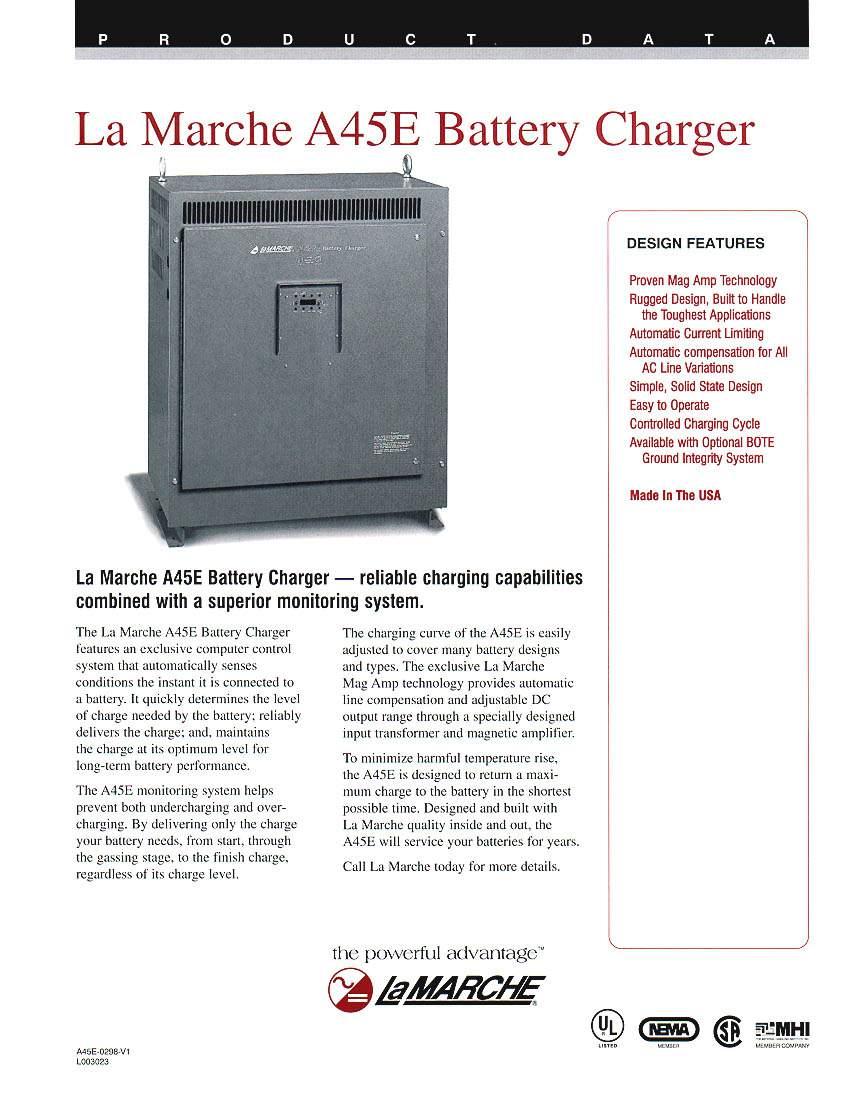
95
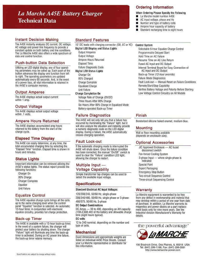
96
 which is bright with clear contrast making them ideal for difficult")


97 A75MD / A75MD Mine Battery Charger (SCR) SCR Technology Mine Battery Charger A75MD Single Circuit A75MD Dual Circuit (Protective Roll Cage Optional) The La Marche model A75MD mine battery charger product line utilizes microprocessor controlled SCR charging technology The A75MD comes with a Vacuum Fluorescent Display (VFD) which is bright with clear contrast making them ideal for difficult lighting conditions This charger features automatic AC line voltage compensation, current limiting and controlled I-E-I charging cycle The I-E-I charge cycle provides constant current start charge rate followed by constant voltage and completing with constant current finish rate The constant current finish rate can be terminated either by DV/DT, voltage limit or time to assure full charge The rugged A75MD is specially designed for the mining market to perform reliably under severe conditions such as moisture, corrosive atmosphere and rugged handling The unit is convection cooled utilizing a 180 C class H insulation system and powder coat paint for durable finish A75MD is a dual circuit charger that allows for charging two batteries at the same time for multiple shift operation convenience Standard Features Available in Many AC Voltage Ratings Microprocessor Controlled Technology Controlled I-E-I Charging Cycle VFD Display Automatic Start / Stop Circuitry Programmable Entry of Battery AH Rating Smart DV/DT Termination Battery Equalize Switch Single Control Plate (Plug & Play) 1 Hour Override Timer Doors Safety Switches LED Indications: Charge ON Charge Cycle Status Charger Mode Fault LED Data Logging Status Digital Display Indicates: DC Volts DC Amps Amp Hours Returned Elapsed Time on Charge Error Codes Operating Temperature 0 to 50 C (3 to 1 F) Limited 5 year Warranty Optional Accessories 05D 1M 1N J 8A 8Q Advanced USB Data Logging Manual Start & Stop Push Buttons External 10 VAC Power Outlet Panel (3KVA) Tropicalization (Magnetics Only) Ground Integrity System (PA SPEC) (18VDC) Ground Integrity System (PA SPEC) (0VDC) IP5 Enclosure Protective Roll Cage Specifications subject to change without notice P5-DSA75MD-1 ECN /15 La Marche Mfg (A US Company) 106 Bradrock Drive, Des Plaines, IL Tel: Fax: sales@lamarchemfgcom wwwlamarchemfgcom

98 18 VDC 6 L * A75MD()-150-6L A75MD()-180-6L A75MD()-10-6L A75MD-70-6L DC Output Amp (Max) Volts Battery Amp- Hour Capacity 100% (8hr High Selectable Rate) AC Input Draw** 80 VAC 575 VAC Case No 6L 6L 6L 6L Overall Dimensions W X D X H 700 x 3700 x x 9398 x 6135mm 700 x 3700 x x 9398 x 6135mm 700 x 3700 x x 9398 x 6135mm 700 x 3700 x x 9398 x 6135mm lbs 1,180 1,60 1,30 1,55 Shipping Weight kgs A75MD-360-6L Consult Factory 0 VDC 10L 30 VDC 160L A75MD() L A75MD() L A75MD-10-10L A75MD-70-10L A75MD L A75MD L Front Panel Display P 6P 6P 6S 6G 6G x 3900 x x 9906 x 6135mm x 3900 x x 9906 x 6135mm x 3900 x x 9906 x 6135mm x 500 x x 1130 x 6135mm 5 x 675 x x 1708 x 711mm 5 x 675 x x 1708 x 711mm All above models designed for optimal performance at 60Hz Consult factory for units designed specifically at 50Hz Consult factory for availability of other DC cell range * Provided specifications are for single circuit A75MD chargers For Dual Circuit chargers A75MD specifications, consult factory ** AC Draws 100% load,305,70,610,980,100,300 1,077 1,100 1,186 1, ,055 Charger Output Ratings in DC Amps Cell 6, 10 or 160 6, 10 or or 10 6 or 10 6 Amp Rating Selectable Output Amp (Amp-Hours) 101 (560) (850) 16(700) 1 (800) - 180(1000) 1 (800) - 16 (100) 16 (100) - 70 (1500) 70 (1500) (000) Nomenclature DC Amps Battery Cell (Lead Acid) Special Frequency When Required * AC Voltage(s) Code AC Phase Code Factory Assigned Accessory Code A75MD A75MD Special Frequency Code 5-50Hz H *60Hz standard unless ZC Special code is entered Y CE - 80/575 HY - 950/1050/1150 AC Voltage Codes C - 80 ZB - 55 E P X A75MD() L - ( ) - ( ) ( ) AC Phase Code 3 - Three Phase Ordering Information When ordering, please specify: - La Marche - Input Voltage and Frequency - Number and Type of Battery Cells - Allowable Recharge Time - Optional Accessories Consult factory for other voltages


99 A75R Series SCR Railroad Battery Charger Model shown: A75R-10-1V A75R-0-1V SCR Railroad Applications Model shown: A75R-30-V A75R-0-1V Model shown: A75R-60-1V The La Marche A75R series battery chargers are specifically developed for the railroad market using proven SCR charging technology Integrated features and functions are ideal for signaling, highway crossing, defect detectors and PTC s (positive train control) This filtered unit is designed and built to charge VRLA, Flooded Lead Acid and Nickel Cadmium batteries A75R s are packed with valued added features to make your DC system more reliable Internal digital temperature Compensation circuitry prolongs battery life with optional external temperature sensor that can be mounted near the battery System State of the art lightning protection circuit protects the unit against lightning surges Charger failure contacts are Provided for remote annunciation Remote shutdown capability allows the user to test DC System integrity or remotely shutdown the unit in emergency situations Mechanically designed to handle the most abusive environmental conditions The A75R is built in NEMA 1 enclosure and equipped with AREMA style hardware for the input and output connections This convection cooled unit has components conservatively chosen to achieve MTBF in excess of 100,000 hours Standard Features Microprocessor Controlled SCR Charging Technology Single Phase AC Input 10/0V, 50Hz/60Hz Automatic AC Input Voltage Compensation +/-10% Complete Isolation AC to DC DC Analog Ammeter and Digital Voltmeter Meets AREMA Specifications Meets ANSI C6-1 Standards for Surge Voltages 3-Year Warranty Enhanced Features Superior Surge and Lightning Protection Automatic AC Input Voltage Selection for 10-0 Amp Models with No Tap Changes Required Integrated Charger Failure Alarm with Form C Contacts Selectable Low DC Current Alarm to detect when charger is not in service (output current is below 1A) Remote Shutdown Capability for Placing Charger Offline for Battery Testing Purposes DC Output Filtering for Higher Quality Battery Charging and Compatibility with Sensitive Loads Even with Battery Disconnected Adjustable Current Limit From 50% to 105% for Coordination with Limited Power Services Higher Temperature (Class H) Transformer Insulation and Conservative Component Selection for Long Life with Greater Safety Margins in Abusive Environments Selectable Temperature Compensation with Optional Smart Solid State External Probe Specifications subject to change without notice P5-DSA75R-1 ECN /16 La Marche Mfg (A US Company) 106 Bradrock Drive, Des Plaines, IL Tel: Fax: sales@lamarchemfgcom wwwlamarchemfgcom
100 A75R-10-1V-AB1 Amps DC Output Volts (Nominal) Battery Cells Lead Acid Ni-Cad AC Input Current 100% (load) Overall Dimensions W x D x H Net Weight* amps / 10 VAC 1 x 10 x amps / 0 VAC 305 x 5 x 8mm lbs kgs A75R-0-1V-AB amps / 10 VAC 33 amps / 0 VAC 1 x 10 x x 5 x 8mm A75R-0-1V-AB amps / 10 VAC 70 amps / 0 VAC 1 x 1 x x 305 x 305mm 58 6 A75R-30-V-AB amps / 10 VAC 83 amps / 0 VAC 1 x 1 x x 305 x 305mm A75R-60-1V-A amps / 10 VAC 167 x 1 x 1 7 x 305 x 305mm A75R-60-1V-B amps / 0 VAC 167 x 1 x 1 7 x 305 x 305mm *Weight does not include shipping packaging Charger Specifications AC Input Single Phase 10/0V ±10% 50Hz/60Hz ±5% Line Regulation ±10% Load Regulation <±05% Input Protection Fuse with surge protection Output Current Limit Factory set at 100%, adjustable from % Output Protection DC breaker or fuse with surge protection Meters DC Output Digital Voltmeter (1%) DC Output Analog Ammeter (%) LED Indicators Current Limit Temperature Compensation Disable AC On Nickel Cadmium Lead Acid Charger Fail Environmental Operating: -0 to 70 C (Output derated above 50 C by 3% with the internal temperature compensation enabled) Storage: -0 to 85 C (-0 to 185 F) Relative Humidity: 0 to 95% non condensing DC Output 1 10 Amps, 0 Amps, 0 Amps and 60 Amps Lead Acid: 5L, 6L, 7L and 8L Ni-Cad: 8NC, 9NC, 10NC, 11NC, 1NC 30 Amps Lead Acid: 10L, 1L, 1L and 16L Ni-Cad: 16NC, 18NC, 0NC, NC, NC Adjustable Voltage Range (per cell) Lead-Acid Cells: 15 VDC to 35 VDC Ni-Cad: 139 VDC to 19 VDC Mounting The enclosures can be wall or shelf mounted Cable Entry Top Finish Powder coat finish (RAL 703) Standards Meets AREMA specifications Meets ANSI C6-1 Optional 11W External Temperature Probe ft 11Y External Temperature Probe 100 ft Nomenclature A75R - 0-1V - AB1- ( ) Ordering Information When ordering, please specify: DC Amps DC Volts AC Voltage Code AC Phase Code Factory Assigned Accessory Code AC Phase Codes AB- 10/0 A- 10 B- 0 AC Phase Code 1 - Single Phase - La Marche - Input Voltage - Number of Battery Cells - Amp Hour Capacity of Battery - Allowable Recharge Time from Full Discharge (where applicable)

")

 AC & DC Breaker Temperature Compensation Float/Equalize Mode Switch Digital Float and Equalize Adjustments Digital Current Limit Adjustment 50 to 110% ±05% DC Voltage")

101 ISO 9001:015 CERTIFIED ESCR 15 INDUSTRIAL BATTERY CHARGER Microprocessor Controlled SCR Battery Charger The La Marche ESCR15 Model is designed specifically to provide an economical and robust solution for Auxiliary DC Control Power Systems in Substations This Smart Microprocessor controlled Battery Charger is designed with PWM controls to provide the highest reliability that is required for maintaining and recharging the batteries, along with supporting the continuous loads in the auxiliary DC system The La Marche ESCR15 is designed per NEMA PE5, C61A and UL safety requirements This Filtered Battery Charger meets NEMA PE5 filtering requirements and has 05% DC voltage regulation from no load to full load (over the specified input voltage, frequency and ambient temperature ranges) Those features along with its Temperature Compensation capability make this model suitable for various types of batteries such as flooded lead acid, VRLA and NiCad Unit Shown: ESCR V-ABD1 ESCR15 is equipped with a two-line LCD which displays output voltage and current, along with an alarm status text description Individual LED indicators provide local supervision, Form C Alarm Contacts and Communication Protocols are available for remote annunciation Standard Features Smart Microprocessor Controlled SCR Technology Filtered Battery Charger Automatic AC Voltage Compensation AC & DC Surge Protection (MOV) AC & DC Breaker Temperature Compensation Float/Equalize Mode Switch Digital Float and Equalize Adjustments Digital Current Limit Adjustment 50 to 110% ±05% DC Voltage Regulation Over Temperature Protection LCD Display Soft Start Meets NEMA PE5 and C61A UL/CUL 101 (Pending) Year Warranty Optional Accessories 080 Drip Shield 09P Conformal Coated Circuit Boards 11W External Temperature Probe ft 11Y External Temperature Probe 100ft 10R AAR Hardware MADE IN USA Specifications subject to change without notice P5-DSESCR15-1 ECN /18 La Marche Mfg (A US Company) 106 Bradrock Drive, Des Plaines, IL Tel: Fax: sales@lamarchemfgcom wwwlamarchemfgcom
102 DC Output Volts (Nominal) Amps DC Breaker Rating Volts (Nominal) ESCR V-ABD kAIC 10/08/0 AC Input Current Draw 37//19 ESCR V-ABD kAIC 10/08/0 58/3/9 Feeder Breaker Size 50/30/30 80/50/0 Case No E E Overall Dimensions W x D x H 153 x 110 x x 79 x 603mm 190 x 150 x 0 * 83 x 381 x 610mm *Floor mounting brackets add (51mm) to overall height Case sizes may differ depending on optional accessories Consult factory when dimensions are critical Detailed dimensional drawings are available for mounting purposes Shipping Weight lbs kg 66 7 AC INPUT 10/08/0 VAC ±10%, 50/60HZ, Single Phase DC OUTPUT 15VDC 15VDC REGULATION Line: <±05% Load: <±05% OUTPUT FILTERING Per NEMA PE5 Filtered Charger PROTECTION Input Breaker with Surge Protection Output Breaker with Surge Protection BATTERY CELL SELECTION 53L-6L 83NC-93NC OUTPUT CURRENT LIMIT Adjustable from % (Factory set at 105%) ADJUSTABLE VOLTAGE RANGE Float Voltage 1-35 volts/cell (Lead) volts/cell (NiCad) Equalize Voltage 5-0 volts/cell (Lead) volts/cell (NiCad) METERING LCD DC Output Digital Voltmeter and Ammeter (1%) CONTROLS Float and Equalize Button Switch from Float to Equalize Configure Button Output Settings Voltage and Cells Adjust Voltage for Float & Equalize Adjust Alarm Settings and Delay High Voltage Shutdown Enable/Disable Temperature Compensation Equalize Timer ~ Multi-Mode Equalize Timer and Light; adjustable from 1-15 hrs ~ Five selectable modes: Manual (Default Factory Setting), 7-day, 1-day, 30-day and Equalize after Low DC Voltage and/or AC Failure Battery Continuity Test Manual and Periodic Battery Test Lamp Test Tests LCD Display & LED s ALARM CONTACTS AC Failure Low DC Voltage High DC Voltage Charger Failure Alarm Form C contact rated 15VAC MONITORING LCD Display Volts Amps Status MONITORING LED Indications Float (Green) Equalize (Yellow) AC ON (Green) Charger Failure (Red) Battery Fault (Red) Current Limit (Yellow) High DC Voltage (Red) Low DC Voltage (Red) Negative Ground Detection (Red) Positive Ground Detection(Red) ENVIRONMENTAL Operating -0º to 70ºC (derated above 50ºC) Storage -0º to 85º C Relative Humidity 5% to 95% non-condensing ENCLOSURE Structural Design Wall/Floor Mount NEMA 1 powder coated Cable Entry Both sides STANDARDS UL 101 (pending) CUL (pending) NEMA PE5 C61A CE (pending) Nomenclature DC Amps DC Volts AC Voltage Code AC Phase Code Factory Assigned Accessory Code AC Voltage Code ABD - 10/08/0 ESCR V - ABD1 - ( ) AC Phase Code 1 - Single Phase Front Panel Display 130V 160A FLOAT MODE


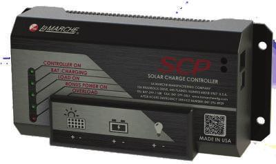
103 SOLAR CHARGE CONTROLLER P5-DSSCP-1 ECN /15 La Marche Mfg (A US Company) 106 Bradrock Drive, Des Plaines, IL Tel: Fax: wwwlamarchemfgcom Specifications subject to change without notice

104 SC SOLAR CHARGE CONTROLLER The La Marche Solar Charge Controller is available in two models, the SCM (Solar Charge Controller MPPT Technology) and SCP (Solar Charge Controller PWM Technology) Both models regulate the voltage and current from the solar modules to properly charge the battery and supply the load In order to maximize the power that can be extracted from the solar modules, the SCM Controller utilizes Maximum Power Point Tracking (MPPT) algorithm For a simplified version, the SCP controller regulates the charging power using Pulse Width Modulation (PWM) The Solar Charge Controller is available in 10A and 0A versions with 1/V auto-select output Both controller models feature built-in protection for solar modules, batteries and load connections Additional features include Low Voltage Load Disconnect, Status LEDs, USB connection for diagnostic parameters and an extra set of output terminals for additional loads Standard Features MPPT/PWM Algorithms Intelligent Micro Controller High Efficiency Compact Design Status LED Indicators Bonus Power Terminal USB Connection Temperature Sensor Lightning and Surge Protection Solar/Battery Reverse Polarity Protection Overload and Short Circuit Protection Reverse Current Flow From Battery To Solar Module Protection Stage Smart Charging: Bulk, Absorption, Float and Equalize* Programmable for Sealed and Flooded Battery Types Low Voltage Load Disconnect (LVLD) * For Flooded Batteries
 Max PV Open Circuit Voltage (Voc) 75V 5V/50V ELECTRICAL Min Solar Input Voltage (Voc) @ Start-up Solar Panel Recovery Voltage Battery Voltage Range Load Voltage 15V 17V 6V-15V 17V-30V 1V/V")
105 TECHNICAL SPECIFICATIONS SCM (MPPT) SCP (PWM) Nominal System Voltage Output Current (A) Nominal Max Input Power 1V/V 1V/V 10A 0A 10A 0A 170W (1V) 30W (1V) 170W (1V) 30W (1V) 30W (V) 680W (V) 30W (V) 680W (V) Max PV Open Circuit Voltage (Voc) 75V 5V/50V ELECTRICAL Min Solar Input Voltage Start-up Solar Panel Recovery Voltage Battery Voltage Range Load Voltage 15V 17V 6V-15V 17V-30V 1V/V 15V/30V 17V/3V 6V-15V 17V-30V 1V/V LVLD (Selectable) 11V or 115V V or 3V 11V or 115V V or 3V LVLR (Selectable) 11V or 16V V or 5V 11V or 16V V or 5V Bonus Power Voltage 1V 1V Max Bonus Power Current A A BATTERY CHARGING Charging Method Temp Compensation Coefficient Temp Compensation Range Bulk/Absorption/Float/Equalize 1V/-30mV/ C and V/-60mV/ C -30 C to +60 C Bulk/Absorption/Float/Equalize 1V/-30mV/ C and V/-60mV/ C -30 C to +60 C USB CONNECTOR PROTECTION LEDs TEMPERATURE SENSOR Solar and Load Overload Short-Circuit High Voltage Reverse Polarity Battery High Voltage Reverse Polarity Other Reverse Current at Night Lightning & Transient Surge Protection LVLD (Low Voltage Load Disconnect) LVLR (Low Voltage Load Reconnect) LED 1 - Controller On LED - Battery Charging LED 3 - Load On LED - Bonus Power On LED 5 - Overload TERMINALS Solar Battery Load Bonus Power Temperature Sensor USB Connector LEDs BATTERY BONUS POWER LOAD SOLAR POWER INPUT

 (SOC) % State State of of Charge: Charge: % PV % Volt PV Volt PV PV Volt Volt (SOC) (SOC) State State (SOC) of Charge: State of State Charge: of % of (SOC) Charge: %")
 Charge: of PV % Charge: PV Volt State % PV Volt of % Volt Charge: % PV (SOC) State of (SOC) Charge: (SOC) State (SOC) % State of (SOC) State Charge: of")
106 Charge Charge State: Charge State: Bulk, Bulk, Absporption, State: Bulk, Charge Absporption, Float State: Charge Float, Bulk, Night, Night Float Absporption, State:, Remote, Bulk, Night Charge Remote Charge Absporption, Temperature: Float State: Charge Remote State:, Charge Night Bulk, State: Temperature: Bulk, Float Celsius State: Bulk, Remote, Celsius Night Bulk, Charge Celsius Temperature: Absporption, Float Remote Float State:, Night Float, Temperature: Night Bulk, Celsius Float, Night Remote Absporption,, Night Remote Celsius Remote Temperature Remote Float, (SOC) (SOC) State of State Charge: of Charge: % (SOC) (SOC) % State State of of Charge: Charge: % PV % Volt PV Volt PV PV Volt Volt (SOC) (SOC) State State (SOC) of Charge: State of State Charge: of % of (SOC) Charge: % State (SOC) % of State State Charge: (SOC) of (SOC) of State Charge: (SOC) % State of State Charge: % of Charge: of Charge: % % (SOC) % (SOC) PV Volt PV Volt PV PV Volt Volt PV State (SOC) Volt PV State of PV Volt Charge: State of Volt (SOC) Charge: of PV % Charge: PV Volt State % PV Volt of % Volt Charge: % PV (SOC) State of (SOC) Charge: (SOC) State (SOC) % State of (SOC) State Charge: of State Charge: of % Charge: of % Charge: (SOC) % PV % State Voltof Charge: PV Volt PV % Volt PV Volt PV Volt Load Load On On Load Load On On Batt Volt Batt Volt Batt Batt Volt Volt Load Load On On Load On On Load On Load Load On OnLoad Load On Load On On Load Batt Volt Batt Volt Batt Batt Volt Volt Batt OnLoad Volt Batt Batt On Volt Volt Load Batt On Batt Volt Batt Volt Volt Ba Load On Load OnLoad OnLoad On Load Batt On Volt Batt VoltBatt VoltBatt VoltVol CHARGE CONTROL USB CONNECTOR TEMP SENSOR DC LOAD CONTROLLER SOLAR CONTROLLER INVERTER AC LOAD BONUS POWER BATTERY Power (Nominal) System Rating Volts (Nominal) Amps Overall dimensions W x D x H Shipping Weight lbs kgs PWM SCP-10-1/V SCP-0-1/V 170W/30W 30W/680W 1/V 1/V x 175 x x 5 x 76mm 675 x 175 x x 5 x 76mm MPPT SCM-10-1/V SCM-0-1/V 170W/30W 30W/680W 1/V 1/V x 175 x x 5 x 76mm 675 x 175 x x 5 x 76mm USB DIAGNOSTICS PARAMETERS Charge On / Off PV Volt PV Current Batt Volt Charge state: Bulk, Absorption, Float, Night State of Charge (SOC) Load On Load Current Bonus On/Off Bonus Power Current Remote Temperature MODEL NUMBER NOMENCLATURE Amps DC Volts SCM /V Amps DC Volts SCP 10 1/ SCM 0 Ordering Specification When ordering, please specify - - DC Amps - DC Volts
 Battery Chargers are specifically designed for maintaining and recharging the dual-battery starting system used on engine driven centrifugal fire")
 The controlled magnetic amplifier technology provides the highest reliability that is necessary for the continued operation of emergency standby")
107 A8/A8B CENTRIFUGAL FIRE PUMP BATTERY CHARGERS USED ON SPRINKLER SYSTEMS Model A8 shown above FOR CHARGING BATTERIES ON INTERNAL COMBUSTION ENGINES DRIVING CENTRIFUGAL FIRE PUMPS USED ON SPRINKLER SYSTEMS The LaMarche A8 and A8B (Base Plate Version) Battery Chargers are specifically designed for maintaining and recharging the dual-battery starting system used on engine driven centrifugal fire pumps for sprinkler systems Both the A8 and A8B models are available in 1 or Volt DC output for either positive or negative ground starting systems The Battery Chargers comply with the standard of the National Fire Protection Association (NFPA No 0) The controlled magnetic amplifier technology provides the highest reliability that is necessary for the continued operation of emergency standby equipment and eliminates most starting problems by maintaining batteries at full charge, ensuring optimum performance and maximum life The A8/A8B is a completely automatic, solid state, constant voltage Battery Charger built to carry continuous and intermittent loads up to 80% of its maximum rated output capacity It automatically senses the battery and load conditions and delivers the necessary amount of charge The A8/A8B Battery Chargers are equipped with a builtin charge divider circuit to isolate and charge two separate sets of batteries of the same nominal DC Voltage either independently or simultaneously The operation is completely automatic a voltage sensing relay is provided to Standard Features Magnetic Amplifier Circuitry Provides Increased Longevity and Worry-free Operation Automatic AC Input Voltage Compensation ±10% Automatic Surge Suppression AC Input and DC Output Fusing Protects Battery and Charger Automatic Float/High Rate Mode Switching Float/High Rate Lights (A8 model only) Charger Failure Alarm Relay with (1) form C Contact Automatic DC Voltage Regulation DC Current Limiting Circuitry (typically less than 15%) Eliminates the Need for Cranking Disconnect Relay 5% Accuracy Analog DC Ammeter & DC Voltmeter (A8 model only) Charger Design Prevents Battery from Discharging if AC Line Fails Complete Isolation of the AC Line from the DC Charging Circuit Environmental: Operating Temperature: 0 to 50 o C (3 to 1 o F) Storage Temperature: -0 to 85 o C (-0 to 185 o F) Relative Humidity: 0 to 95% Non-condensing AC Input Voltages of 10, 08 or 0, Single Phase, 60Hz NEMA 1 Enclosure ANSI 61 Gray Baked Enamel Paint (A8 model only) All A8 and A8B models are UL 136 and CSA Listed Industry s unparalleled 10-year Warranty automatically transfer the output of the Battery Charger to the high rate charge mode, after engine cranking or following a power failure This will bring the batteries to a fully charged state within hours Once the batteries are fully charged, the relay will automatically transfer the charge rate back to the Float rate to prevent overcharging and protect the batteries The A8/A8B Battery Chargers are designed and built for use on Flooded Lead-Acid or Nickel-Cadmium Batteries and are not suitable to charge Sealed Valve- Regulated Batteries since these require output filtering such as a Power Supply (see our model A1B for this type of application) The Controlled Magnetic Amplifier circuitry provides years of trouble-free operation our confidence in the reliability of our A8/A8B is reflected by our unparalleled and Industry leading 10-year Warranty The A8/A8B assures the quality, reliability and performance you have come to expect from LaMarche LaMarche Manufacturing Company 106 Bradrock Drive, Des Plaines, IL Tel: Toll Free Fax: sales@lamarchemfgcom wwwlamarchemfgcom Made in USA
 6L, 9 or 10 NC 1L or 0 NC 6L, 9 or 10 NC 1L or 0 NC 50A 50A 50A 50A AC Input Current Draw @ 100% Load (Amps)* A 10 71 15 71")
 AC input Right Right N/A N/A DC output Left Left N/A N/A M ou n ti n")
108 A8 and A8B Models Model Number A8-0-1VP A8-0-1VN A8-0-VP A8-0-VN A8B-0-1VP A8B-0-1VN A8B-0-VP A8B-0-VN System Ground Positive Negative Positive Negative Positive Negative Positive Negative Amps Volts V V 1V V DC Output Battery Cell Fuse Range Size (choose only one) 6L, 9 or 10 NC 1L or 0 NC 6L, 9 or 10 NC 1L or 0 NC 50A 50A 50A 50A AC Input Current 100% Load (Amps)* A D A8 / A8B CENTRIFUGAL FIRE PUMP BATTERY CHARGERS USED ON SPRINKLER SYSTEMS B C as e N o 7 7 7B 7B Overall Dimensions W x D x H 150 x 1065 x x 70 x 505 mm 150 x 1065 x x 70 x 505 mm x 9000 x x 9 x 36 mm x 9000 x x 9 x 36 mm Cable Entry (when facing unit) AC input Right Right N/A N/A DC output Left Left N/A N/A M ou n ti n g Wall / Floor Wall / Floor Base Plate Base Plate Shipping Weight (Approx) lbs kgs *AC Current Draws 100% load and standard battery cells of 6L(1V) and 1L(V) All above models designed for optimal performance at 60Hz They will operate at 50Hz with reduced performance Consult factory for units designed specifically at 50Hz Must specify only one battery type and number of cells Please consult factory for other available cell ranges if desired range not shown Maximum Current Draw is typically 15% of ratings shown Other Sizes Available - Contact Factory for further information Base Plate Photo Ordering Information When ordering, please specify: LaMarche A8 or A8B (Base Plate) Input Voltage of 10, 08 or 0 VAC/Single Phase/60Hz Number and Type of Battery Cells AH Capacity of Batteries Intermittent DC Loads and Duration Continuous DC Load Allowable Recharge Time from Full Discharge (where applicable) Nomenclature (B) designates Base plate Version DC Amps DC Volts (P) designates Positive Ground (N) designates Negative Ground AC Voltage Code AC Phase Code Battery Cell Range Factory Assigned Accessory Code A8(B) - 0-1V(P) - A1 - ( ) - ( ) AC Voltage Code A - 10 B - 0 D - 08 AC Phase Code 1 - Single Phase Specifications subject to change without notice P5-DSA8_A8B-1 ECN: Bradrock Drive, Des Plaines, IL Tel: Toll Free Fax: sales@lamarchemfgcom wwwlamarchemfgcom

109 A63 DC-DC CONVERTER SYSTEMS ISO 9001 CERTIFIED 19 and/or 3 PC63 Cage shown above with () A63 Converters and a TPCDB1 Distribution Module A63 DC-DC CONVERTER SYSTEMS The unique design of the LaMarche A63 Series DC-DC Converters will allow you to utilize your 8V, V, and/or 1V equipment at a site where 130V batteries are installed This will save battery, charger, and installation costs as well as reducing maintenance time and optimizing space The A63 is a compact self contained DC-DC Converter that provides the Modular Power that today s utility substation, process control and telecommunications applications require The A63 is the building block of these reliable systems using advanced switching technology Its filtered output provides the clean power required for sensitive loads Typical System Diagram LaMarche Switchmode A96/A97 Battery Charger 130V Battery A63 DC-DC Converters 130V-8V 130V-V 130V-1V 8V Load V Load 1V Load 130V Load The A63 DC output is available in 8V (15 amps) and V (30 amps) rated at 750W, or 1V (30 amps) modules rated at 375W The converter modules are hot-swappable plug-in type Installation or replacement is swift, simple, and achieved without affecting the integrity of the system Its versatile design allows the DC output to be wired as a single connection for all converters or for each pair of converters per cage This allows for custom field installations and gives greater system flexibility to suit the customer needs and preferences A63 Converter Systems are factory configured with one to four Modules in a single cage Distribution Modules consisting of either GMT Fuses (TPCD) or Breakers (TPCDB1) can share a cage with the converters to form a complete Power System Rely on LaMarche quality, reliability and performance to power your present and future system needs Standard Features LaMarche Manufacturing Company 106 Bradrock Drive, Des Plaines, IL Tel: Toll Free Fax: sales@lamarchemfgcom wwwlamarchemfgcom High Frequency Switchmode Circuitry Provides High Power Density Hot Plug-In Feature Provides Easy Replacement Without Disturbing System Operation 8VDC and VDC Versions 750 Watts Output Power 1VDC Version 375 Watts Output Power 19 and 3 Rack Mounting (using PC63 cages) Nominal Input Voltage of 130VDC, Range from VDC DC Input Breaker Mounted on Cage for Each Converter Module (wired in positive leg) Output Voltage Adjustment Potentiometer Test Points for Measuring Output Current and Voltage Using a Precision Multi-Meter Current Limiting Circuitry of 105% Maximum (factory set) Filtered/Battery Eliminator Design less than 150mVp-p, 3db rn C Message Weighted 8% Efficiency within 50 to 100% of Rated Load Load Sharing Circuitry (10% of rated load) Soft Walk-In Circuit Over Temperature and Voltage Protection Converter Failure Alarm with (1) Set of Form C Contacts with Light (Alarm will Initiate for either Low Voltage, High Voltage Shutdown, Low DC Current, Converter Failure or DC Breaker Tripped) -Year Limited Warranty Made in USA
110 A63 DC-DC CONVERTER SYSTEMS Electrical DC Input Voltage Range VDC Protection DC Breaker provided on cage for each unit DC Output Adjustable Output Voltage Range 8 to 58VDC on 8V models to 9VDC on V models 1 to 15VDC on 1V models Power 750W per 8VDC and VDC module, maximum 3000 Watts per cage 375W per 1VDC module, maximum 1500 Watts per cage Voltage Regulation ± 06% Total DC Voltage Regulation (Measured at converter side of blocking diode) Current Limit 105% of rated output maximum (factory set) Load Sharing Load Sharing Circuitry (10% of rated load) Protection Over Voltage, Over Temperature Efficiency 8% within % of rated load Ripple and Noise Less than 150mV peak to peak, 3db rn C message weighted A63 Modules Model Number A V-130V A63-30-V-130V A V-130V PC63 Cages Model Number PC V-130V PC63-10-V-130V PC V-130V PC V-130V PC63-60-V-130V PC V-130V DC Output Amps DC Output Volts 8 1 Description 1- modules 1- modules with TPCD or TPCDB1 DC Input Voltage Range No of Available Bays +1 DC Output Amps Units can be mounted flush with the rack or moved forward 5 inches (17mm) Allow an additional 075 inches (19mm) for handles Enclosures A63 DC-DC Converters Dimensions 35 Wx110 Dx55 H (83x79x133 mm) Weight 7 lbs each (3 kgs) Mounting 19 /3 Rack Mount PC63 Cages Typical DC Input Current Load (Amps) DC Output Volts Rack Mounting 19 /3 19 /3 19 /3 19 /3 19 /3 19 /3 Test Points For output current and output voltage using a precision digital voltmeter Environmental FCC Approved Part 15, Subpart B, Class A IEC-555- Compliant Operating Temperature: 0 to 50 O C (3 to 1 O F) Storage Temperature: -0 to 85 O C (-0 to 185 O F) Relative Humidity: 0 to 95% (non-condensing) Altitude: 0 to 3,000 meters (10,000 ft) PC63 Cages Dimensions for 19 or 3 Rack 185 W x 159 D x 875 H (6x388x mm) Weight 6 lbs Mounting PC63= 5 RU s Agency Approvals UL Recognized Component TPCD Distribution Module GMT Fuses (For further details on this product refer to the TPM Systems Data Sheet) TPCDB1 Distribution Module Breakers (For further details on this product refer to the TPM Systems Data Sheet) Specifications subject to change without notice P5-DSA63-1 ECN ISO 9001 CERTIFIED LaMarche Manufacturing Company 106 Bradrock Drive, Des Plaines, IL Tel: Toll Free Fax: sales@lamarchemfgcom wwwlamarchemfgcom


")
 (available on 1KVA and larger) 1ms Static Transfer Switch (Inverter Standby) (available on 1KVA and")
111 ISO 9001:015 CERTIFIED A31 DC-AC Inverter A31 DC-AC Inverter The La Marche A31 Inverter is the ideal choice when AC power requirements are critical This inverter has a wide range of standard features such as a sine wave output, voltage regulation, protection from AC-DC shorts, under/over-voltage conditions, input filtering and overload protection It incorporates a DC input breaker and an automatic under/over-voltage shutdown circuit to protect the inverter The A31 has a polarity indicator to tell you if the battery is connected incorrectly The unit is equipped with an input filter pre-charge circuit which includes an indicator to inform you that the inverter is ready for operation Applications may include data centers, fire alarms, telecommunications, emergency lighting, security, oil exploration and utility substation systems Unit shown with optional 1ms Static Transfer Switch & Digital Display Available in 50 or 60 Hz 10, 0, 08 or 0 AC Output Standard Features Highly Reliable Ferroresonant Transformer Available DC Inputs V or 8V or 10V DC to AC Isolation Pure Sine Wave Output Adjustable DC Under/Over Voltage Shutdown Analog AC Ammeter & Voltmeter (%) (Optional on 50 VA & 500 VA) Overload/Current Limit Inverter On/Off Switch AC Circuit Breaker DC Circuit Breaker IGBT Power Block Technology UL 101 Listed, UL 181 Listed (selected models) and C-UL Listed 5-Year Limited Warranty P S 09A 16 Options 1ms Static Transfer Switch (Inverter Prime) (available on 1KVA and larger) 1ms Static Transfer Switch (Inverter Standby) (available on 1KVA and larger) A Static Switch Alarm Package consisting of the following: Form C Contacts for Phase Lock, Utility Available, Inverter Available, Load on Preferred, Load on Alternate, Requires P or S D Digital Display (replaces AC analog meters) Used only with 1ms Static Switch Requires P or S UL ms Static Switch Transfer (Inverter Prime) (not available on KVA & above) ms Static Switch Transfer (Inverter Standby) (not available on KVA & above) 130 Inverter Failure Relay and Light (not available with option A) 13 Inverter Failure Relay (1 Form C ) (not available with option A) 133 Utility Available Relay (1 Form C ) (not available with option A) 13 Duplex Receptacles (not UL Listed) 06L AC Ammeter (Std on 750 VA and larger) 06M AC Voltmeter (Std on 750 VA and larger) 06C DC Ammeter (%) 06D DC Voltmeter (%) MADE IN USA Specifications subject to change without notice P5-DSA31-1 ECN /18 La Marche Mfg (A US Company) 106 Bradrock Drive, Des Plaines, IL Tel: Fax: sales@lamarchemfgcom wwwlamarchemfgcom
112 * ** *** **** (1) DC Input Amps AC Output BTU Case Approx Weight No Load Full Load*** VA Volts Amps Hour*** No lbs kgs A31-50-V-A A V-A A V-A (1) (1) A31-1K-V-A D (1) A31-15K-V-A D (1) A31-K-V-A E* DC Input Amps AC Output BTU Case Approx Weight No Load Full Load*** VA Volts Amps Hour*** No lbs kgs (1) A V-A (1) A V-A (1) A V-A (1) A31-1K-8V-A D (1) A31-15K-8V-A D (1) A31-K-8V-A E* (1) A31-3K-8V-A E* (1) A31-K-8V-A E* (1) A31-5K-8V-A E* A31-10K-8V-A ** DC Input Amps AC Output BTU Case Approx Weight No Load Full Load*** VA Volts Amps Hour*** No lbs kgs A V-A A V-A A V-A A31-1K-10V-A D A31-15K-10V-A E* A31-K-10V-A E* A31-3K-10V-A E* A31-K-10V-A E* A31-5K-10V-A E* A31-75K-10V-A ** A31-10K-10V-A ** A31-15K-10V-A ** Case Type Case Height Width**** Depth Relay Rack RU No Floor 19 3 in mm in mm in mm 39 N/A N/A N/A D N/A N/A E N/A N/A N/A N/A N/A N/A N/A N/A N/A N/A N/A Requires a heat baffle when or more units are used Floor mount case only (all others are rack mounted) Typical at full load and minimum input voltage Main body width of case on relay rack units Side mounting angles located 750 from front of relay rack UL 181 Listing Available Input Specifications Battery Ranges volt nominal 1-30VDC 8 volt nominal -60VDC 10 volt nominal VDC Input Reverse Polarity Protection Indicator Filter Pre-charge Circuit; DC Breaker DC Under Voltage Shutdown Adjustable DC Over Voltage Shutdown Adjustable Output Specifications AC Output Voltage 10V Nominal (Standard) 0V (Optional) 08V and 0V (Optional, Not UL Listed) Output Power Rated VA continuous for unity to 8 lagging power factor Line Regulation ±3% Over DC Battery Range Load Regulation ±% from no load to full load Frequency Regulation ±05% (Quartz Clock) Current Limit Approximately 150% Protected by AC Output Breaker Total Harmonic Distortion Approximately 5% at nominal DC Input and Full Load Less than 3% for any single harmonic Noise Less than 3 dbrn C message weighted with a battery (VDC and 8VDC only) Audible Noise 65 5 feet Approximate Efficiency VDC models 70-75% 8VDC models 85-90% 10VDC models 85-90% Load Crest Factor Will operate with Load Crest Factors up to 8 Environmental Operating Temperature 0 to 50 C Storage Temperature -0 to 60 C Relative Humidity 0-95% (non-condensing) Convection Cooled (3KVA and larger units may be fan assisted) Agency Approvals UL 101 UL 181 (Available for selected models, refer to chart) C-UL Ordering Information When ordering, please specify: - La Marche A31 Inverter - Desired output power (VA) - Battery type and number of cells - Output voltage and frequency - Description of load - Optional Accessories

113 P / S Static Switch 1MS Electronic Transfer Switch Fast Electronic Static Switch for La Marche A31 DC to AC Inverter The La Marche Electronic Static Switch is an automatic device that will transfer an AC load to and from the Prime Source to an Alternate Source, if the Prime Source fails, in less than millisecond The Static Transfer Switch is intended for use on the La Marche A31 DC to AC Inverters ranging from 1kVA to 15kVA models (consult factory for other applications) A customer calibration mode is incorporated into the Static Switch Menu to allow for on site settings that are best suited for the intended application Frequency 600Hz 500V/DIV 00ms/DIV indicates when transfer occurs Scope photo shown above of typical Static Switch Transfer from Inverter Prime Source to Alternate Source upon loss of Inverter Output A Digital Display Panel, which replaces the unit s AC analog meters, is also offered as an option The Digital Display will allow the operator to view Load Voltage, Load Current, VA (Volt-Amps), Utility Voltage, Utility Frequency, Inverter Voltage and Inverter Frequency readings Status Display A Status Display panel consisting of (5) LED indicator lights and () switches are provided on the front of the unit Phase Lock Utility Available Inverter Available Load on Preferred Source Load on Alternate Source Auto/Manual Switch Test Transfer Pushbutton Customer Calibration Mode SELECTIONS 1 Preferred Source Load Voltage Window Upper Limit 3 Load Voltage Window Lower Limit Utility Voltage Upper Limit 5 Utility Voltage Lower Limit 6 Inverter Voltage Upper Limit 7 Inverter Voltage Lower Limit 8 Inverter Sense Delay Indicates when the Prime and Alternate sources are in synchronization Indicates the Alternate source is connected and operating within its proper range Indicates the Inverter is operating within its proper range Indicates the AC load is operating on the Prime source Indicates the AC load is operating on the Secondary source Allows for an Automatic or Manual Transfer Allows an active check of the Static Switch operation The customer calibration mode allows the user to select the available parameters and to set per preferences 9 Utility Sense Delay 10 Retransfer Delay 11 Hit Counter SETTINGS May be selected to either Utility or Inverter Maximum voltage allowed on the Load Minimum voltage allowed on the Load Maximum voltage allowed for Utility to be considered good Minimum voltage allowed for Utility to be considered good Maximum voltage allowed for Inverter to be considered good Minimum voltage allowed for Inverter to be considered good The amount of time the Inverter must be within the upper and lower limits before the Inverter is considered within tolerance The amount of time the Utility must be within the upper and lower limits before the Utility is considered within tolerance Used to set the time the Static Switch will attempt retransfer from the Alternate Source to the Primary Source Used to determine the maximum allowable load voltage deviations outside of the pre-defined envelope that will trigger a transfer Static Switch Options Option #A Alarm Relay Board consisting of () sets of Form C Contacts for each of the following: Phase Lock Utility Available Inverter Available Load on Prime Source Load on Alternate Source Option #D Digital Display (replacing AC analog meters on unit) to indicate the following: Load Voltage Load Current VA (Volt -Amps) Utility Voltage Utility Frequency Inverter Voltage Inverter Frequency


114 Manual Bypass Switch For AC Applications Manual Bypass Switch The Manual Bypass Switch (MBS) provides a mechanical means to transfer between power sources to your critical loads Whether you are performing regular schedule maintenance on the system or in the event of an unexpected system malfunction, the power to the load can be safely transferred without being interrupted *Back Cover Not Shown La Marche offers two types of MBS configurations, a Make-Before-Break (MBB) and a Break-Before-Make (BBM) The MBB switch links both primary and secondary sources momentarily before completing the transfer The MBB is the preferred configuration for use with critical loads Rack Panel Inverter Rating Rack Units 0A 5A 75A 00A 50 TO 15kVA k to kva 5kVA 75 to 15kVA 3 8 Wall Mount Inverter Ratings Case No in Width mm in Depth mm in Height mm 0A 50 TO 15kVA A k to kva A 5kVA A 75 to 15kVA Standard Features Input & Output Terminal Block Option Rotary CAM Type Switch - Position for Complete Isolation Rack or Wall Mount available UL Listed Bypass Switches 0 to 00 AMP Rating Switches 06J - Frequency Meter (available for MB3 & MBW) Nomenclature Mounting MB 19-0A - MBB Mounting 19 - Mounting for 19 Rack 3 - Mounting for 3 Rack W - Wall Mount MBB - Make Before Break BBM - Break Before Make Amps Amps 0A 5A 75A 00A Note: For use on 10 VAC Inverters For other AC Voltages consult factory
 input and produce either 10VAC or 30VAC nominal output at up to 6kVA total capacity The low distortion 50 or 60 Hz sine wave is produced using an")
115 ISO 9001:015 CERTIFIED IX SERIES High Frequency / Hot-Swap Inverter Systems Fully Equipped 3KVA System with Optional SNMP Module IX Series This IX Inverter Series offered by La Marche Manufacturing is designed to operate from a 8VDC (05-58V range) input and produce either 10VAC or 30VAC nominal output at up to 6kVA total capacity The low distortion 50 or 60 Hz sine wave is produced using an advanced DSP controlled architecture which achieves better than 89% efficiency and 105VA per cubic inch power density The IX Series pre-configured inverter systems include a Controller, Static Transfer Switch, Power distribution and Maintenance by-pass facilities Remote communications to a PC is provided via USB, RS3 or RS85 serial connections SNMP alarm traps delivered over an Ethernet TCP/IP connection are also available as an option Inverter Modules 006/95/EC Output Power Output Voltage Output Frequency 1 Model Number 08PF 1PF 10VAC 30VAC 60Hz (50Hz) 50Hz (60Hz) Notes: 1 The frequency shown in parenthesis can be obtained by reprogramming the unit from the system controller INV158-LMC-1 INV158H-LMC-1 Standard System Configurations Model Number 3 Max Output Power Max No Modules Output Voltage 1 Output Frequency Network Module Distribution Socket Type Manual Bypass Rack Height IXU-1-TS50-DE-M-LMC-1 3KVA kw 10VAC or 30 VAC 60Hz / 50Hz 8 x IEC60-30 YES U IXU-1-TS50-DN-M-LMC-1 3KVA kw 10VAC or 30 VAC 60Hz / 50Hz 8 x NEMA 15-5 YES U IX5U--TS50-DE-M-LMC-1 6KVA 8kW 10VAC or 30 VAC 60Hz / 50Hz 8 x IEC60-30 YES 5U IX5U--TS50-DN-M-LMC-1 6KVA 8kW 10VAC or 30 VAC 60Hz / 50Hz 8 x NEMA 15-5 YES 5U IXU-1-TS50S-DE-M-LMC-1 3KVA kw 10VAC or 30 VAC 60Hz / 50Hz 8 x IEC60-30 YES U IXU-1-TS50S-DN-M-LMC-1 3KVA kw 10VAC or 30 VAC 60Hz / 50Hz 8 x NEMA 15-5 YES U IX5U--TS50S-DE-M-LMC-1 6KVA 8kW 10VAC or 30 VAC 60Hz / 50Hz 8 x IEC60-30 YES 5U IX5U--TS50S-DN-M-LMC-1 6KVA 8kW 10VAC or 30 VAC 60Hz / 50Hz 8 x NEMA 15-5 YES Notes: 1 Inverter modules must be ordered separately based on output voltage and total system capacity required Module types may not be mixed in the same system 10VAC inverters are pre-programmed to 60Hz, 30VAC inverters are pre-programmed to 50Hz These settings can be changed from the front panel of the controller or remotely using the WIN-power client application 3 M = Mid Mounting Provided via IEC to NEMA adapters 5U Standard Features Hot-Swap Inverter, STS and Controller Modules 19 inch Rack Mounting 1500 to 6000 VA System Capacity 10VAC or 30VAC Low Distortion 50 or 60Hz Pure Sine Wave 05 to 58 VDC Input DSP Management & Control > 89% Efficiency 1-year Warranty Optional Features 3 inch Rack Mounting Kit Specifications subject to change without notice P5-DSIX- ECN /18 La Marche Mfg (A US Company) 106 Bradrock Drive, Des Plaines, IL Tel: Fax: sales@lamarchemfgcom wwwlamarchemfgcom
116 SPECIFICATIONS Typical at 8V Input, Full Load and 5 C Unless Otherwise Noted INVERTER MODULES INPUT Voltage Range 05-58VDC Undervoltage Warning Threshold 5VDC Undervoltage Threshold 0VDC Overvoltage Warning Threshold 58VDC Overvoltage Threshold 60VDC Input Current, 8VDC Input 8A Input Protection Fused Reverse Polarity Protection Inrush Current Less than x Rated Iin (IEC ) Isolation Input to Output Reinforced Pri-Sec, VDC / 1 min Input to Ground 707VDC (Varistor & filter caps removed) Psophometric Noise Voltage <1mV ITU-T 01 ( Hz) Reflected Psophometrics Noise Current <1% YD/T Refl ected Relative Band Wide Current <10% YD/T (0-MHz) Wide Band Noise <0mVrms (5Hz-0kHz) Peak to Peak Noise <150mV up to 100MHz OUTPUT AC Waveform Pure Sine Wave Output Power 08PF OR 1PF Power Factor or Load -08 to +08 Rated Output Voltage 10VAC or 30VAC (see model table) Output Voltage Variation <±% Output Frequency 50Hz or 60Hz (see model table) Frequency Variation <±05% Crest Factor 3:1 max THD of Voltage Waveform Linear Load <3% Non-Linear Load <5% Capacitive/Inductive Load +08 to +08 PF without exceeding permissible distortion for resistive load Effi ciency >89% Overload Protection Electronic Current Limit at Overload & Short Circuit 15 x Rated Current, Temperature Controlled 150 x Rated Current for Periods <0 Seconds Dynamic Response <±10% Isolation, Output to Chassis Basic Isolation (Pri-Gnd) 11 VDC/1 min Surge Protection EN Telcordia GR-1089 Core ANSI C61-IEEE, STD Load Sharing <5% of Rated Load CONTROL/STATUS LED Indicators Inverter Status Green OK, Red FAIL Overload Off OK, Yellow for Overload Reverse Polarity Off OK, Red for Reversed Status/Alarm Information (via controller) Inverter Fail, Overload, LVD Alarm, Fail Alarm, Thermal Derating, Power Output, Input Voltage, Output Voltage, Output Current, Output Frequency, Low Input Voltage Shutoff, Inventory Data Runtime Info Through Maintenance Feature in Controller STATIC TRANSFER SWITCH (STS) INPUT Voltage Range 110/115/10VAC Systems VAC 08/0/30/0VAC Systems VAC Over / Undervoltage Threshold (adjustable from controller) 110VAC Systems 117 to 17VAC / 89 to 105VAC 115VAC Systems 1 to 13VAC / 93 to 110VAC 10VAC Systems 17 to 138VAC / 100 to 11VAC 08VAC Systems 0 to 0VAC / 176 to 198VAC 0VAC Systems 33 to 5VAC / 176 to 09VAC 30VAC Systems to 6VAC / 185 to 18VAC 0VAC Systems 5 to 76VAC / 193 to 8VAC OUTPUT AC Waveform Sine Wave Output Voltage Same as utility or inverter modules Permissible Frequency Variation to Synchronise Inverters ±5% Transfer Time Typically 1/ cycle Rated Current 50A Operation Modes (programmable) Inverter Priority or Utility Priority Default Priority Inverters CONTROL/STATUS LED Indicators Fault (red) Off OK, On FAIL Warning (yellow) Off OK, Flashing for warning condition Power On (green)on OK, Flashing for bypass Status/Alarm Information CAN communication failure back-feed relay open, SCR short, output short, overload over temperature, mains unavailable, inverter unavailable output abnormal, fan failure, MBS position error GENERAL ENVIRONMENTAL Operating Temp Range Without Derating -5 C to 50 C With Derating -0 C to 70 C Storage Temp Range -0 C to +85 C Humidity0% to 95%, Non-Condensing Cooling Variable Speed Internal Fans (Field Replaceable) Operating Altitude 1500m without derating REGULATORY Safety Inverter/PDU/MBS/chassis UL , EN , IEC STS module UL1778 EMC (individual modules) EN :001 Class B Acoustic Noise (individual modules) 55dB ETS , Class 31 Safety Standards UL CSA, No EN


 RS-3 RS-85 SNMP USB CAN bus interface embedded Programmable dry contact Hot swappable Real time clock embedded LCD and LED")


117 IFC1000 Standard Interface Module The IX Series Standard Interface Module provides system connection to a computer via RS3, RS85 or USB for the purposes of remote monitoring, control or programming Remote PC based software provides a user friendly GUI interface Standard Interface Module The Network Interface Module with SNMP (integral to the STS/Controller shelf) provides alarm traps over a TCP/IP Ethernet interface Network Interface Module with SNMP DSC08 Controller Module The IX Series Controller, allows the user to monitor real-time system status such as output voltage, output current, alarm status, and also allows system parameters to quickly be changed with the touch of a few keys on the front panel With the Communications Interface Module installed remote access can be made with a PC over a variety of interfaces Compact design (1RU height) RS-3 RS-85 SNMP USB CAN bus interface embedded Programmable dry contact Hot swappable Real time clock embedded LCD and LED indicator Audible alarm DPMBSU Manual Bypass / Distribution Module The IX Series manual bypass and power distribution module enables the user to manually switch between inverter output or utility output and to override the STS module for maintenance purposes A mechanical interlock between the DPMBSU and the STS module ensures that AC to the load cannot be inadvertantly interrupted The DPMBSU provides two means of distributing AC to the load as standard; as a single bulk output or via eight IEC30 outlet sockets with Magnetic Circuit Breakers Bypass switch Enables hot-swap of STS module 50A bulk output on terminal block AC utility can be isolated via MCB 100A master MCB 8 x IEC30-C13 (-E) Distribution MCBs
118 TABLE OF CONTENTS 3KVA SYSTEM CONFIGURATIONS Rear views are with safety covers removed to show input and output connection details IXU-1-TS50S-DE-LMC Bulk AC Output / 8 x IEC6030-C13 Outlets - 10VAC or 30VAC STS Hot-Swappable using Manual Bypass SWITCHED OUTPUT BREAKERS (X 0A) BULK OUT BREAKER (100A) UTILITY IN BREAKER (100A) MANUAL BYPASS SWITCH S1-S MSS NORM ISS MBP IBP S3-S S5-S6 OUTPUT 100A INPUT 100A S7-S8 RS85 STS MODULE CONTROLLER Settings SNMP USB RS3 INVERTERS Front View (Shown with optional SNMP Module) SWITCHED OUTPUTS (10/30VAC) 8X IEC6030-C13 10/30VAC UTILITY IN L N G L N BULK 10/30 VAC OUT G RS85 RS3 Rear View 6KVA SYSTEM CONFIGURATIONS Rear views are with safety covers removed to show input and output connection details IX5U--TS50S-DE-LMC Bulk AC Output / 8 x IEC6030-C13 Outlets - 10VAC or 30VAC STS Hot-Swappable using Manual Bypass SWITCHED OUTPUT BREAKERS (X 0A) BULK OUT BREAKER (100A) UTILITY IN BREAKER (100A) MANUAL BYPASS SWITCH S1-S MSS MBP S3-S NORM ISS IBP S5-S6 OUTPUT 100A INPUT 100A S7-S8 RS85 STS MODULE CONTROLLER Settings SNMP USB RS3 INVERTERS Front View (Shown with optional SNMP Module) SWITCHED OUTPUTS (10/30VAC) 8X IEC6030-C13 10/30VAC UTILITY IN L N G L N BULK 10/30 VAC OUT G RS85 RS3 Rear View

 patented test to check whether the battery has good, missing, open,")
119 STATIONARY BATTERY INFORMER US PATENT NO 6,99,87 The La Marche Stationary Battery Informer (BI) is a breakthrough in technology This tester can be installed in any battery system The BI can determine the condition of your batteries under load without disrupting the system operation The battery and charger are never disconnected from the load even during the test The intelligent tester control circuit will not allow testing to take place while the batteries are being used in an emergency situation or if they are recharging from a recent discharge It will also signal if the tester has failed and/or the charging system is inoperative The Battery Informer performs a factory set 1 minute (adjustable to or 3 minutes) patented test to check whether the battery has good, missing, open, or sulfated cells and displays results If the tester detects suspected sulfation, an automatic equalize cycle can be initiated on a charger equipped with a remote equalize feature The test can be initiated manually or the controller can be programmed to automatically perform the test periodically BI Battery Informer Series US Patented Shown: BI V-300-9N This patented BI has the capability to store battery discharge curve as a benchmark to analyze battery health trends The Battery Informer offers an optional DNP3 or MODBUS communication interface This allows downloadings of test results to a computer and compare with previous test performed on the battery The Battery Informer is available in several models covering battery strings of, 8 and 130 Volts with capacities ranging from 5 to 1000 ampere hours Contact the factory for other system ratings Standard Features Online Battery Test System Manual Test Mode Programmable Auto Test Interval (Adjustable 1 to 10 day interval) Battery and charger are never disconnected from load Automatic Self-Diagnostic LCD Display LED s provided for: Test Pass Test in Process Manual Test Check Battery System Open Cell Detected Tester Failure Relay Contacts - () Sets of Form C Contacts each - Summary Failure Alarm** - Remote Auto Equalize Control - Charger Inoperative Alarm - Tester Failure Alarm - Test in Process Relay ** Summary Failure is defined as any of the following Alarms: Open Cell, Possible Battery or Tester Failure MADE IN USA Specifications subject to change without notice P5-DSBI-1 ECN /13 Optional Accessories 068 1P 1Q 19Q Audible Alarm with Silence Switch Uses (1) set of Summary contacts DNP3 Communications Protocol Modbus Communications Protocol Quadrant System (Refer to Quadrant System guide)* *La Marche Mfg Co does not provide the wires/hardware necessary to connect to the battery at these taps (18 AWG is recommended) La Marche Mfg (A US Company) 106 Bradrock Drive, Des Plaines, IL Tel: Fax: sales@lamarchemfgcom wwwlamarchemfgcom
120 130VDC VDC 8VDC 8VDC VDC Battery Informer (BI) Models BATTERY INFORMER SERIES (US PATENTED) LIVE CIRCUIT BATTERY TESTING STATIONARY BATTERY INFORMER Case Size Battery Amp Hour Range Continuous Load 0-100A Continuous Load 0-00A Continuous Load 0-00A B B B B B BI-100-V-50 BI-100-V-100 BI-100-V-150 BI-100-V-300 BI-100-V-00 BI-100-V-500 N/A N/A N/A N/A N/A N/A N/A N/A N/A N/A N/A N/A N/A N/A N/A N/A N/A BI-00-V-600 BI-00-V-600 BI-00-V-700 BI-00-V-800 BI-00-V-900 BI-00-V-1000 BI-00-V-700 BI-00-V-800 BI-00-V-900 BI-00-V-1000 Case Size Battery Amp Hour Range Continuous Load 0-100A Continuous Load 0-00A Continuous Load 0-00A B B B BI-100-8V-50 BI-100-8V-100 BI-100-8V-150 BI-100-8V-300 BI-100-8V-00 BI-100-8V-500 N/A N/A N/A N/A N/A N/A N/A N/A N/A N/A N/A N/A N/A N/A N/A N/A N/A BI-00-8V-600 BI-00-8V-600 BI-00-8V-700 BI-00-8V-800 BI-00-8V-900 BI-00-8V-1000 BI-00-8V-700 BI-00-8V-800 BI-00-8V-900 BI-00-8V-1000 Case Size Battery Amp Hour Range Continuous Load 0-100A Continuous Load 0-00A Continuous Load 0-00A B B BI V-50 BI V-100BI V-150 BI V-300BI V-00BI V-500 N/A N/A N/A N/A N/A N/A N/A N/A N/A N/A N/A N/A N/A N/A N/A N/A N/A BI V-600 BI V-700 BI V-800 BI V-900 BI V-1000 BI V-600 BI V-700 BI V-800 BI V-900 BI V-1000 Case Specifications Case No Overall Dimensions Width Depth Height* in in in B * Including floor mounting bracket Approximate Unit Shipping Weight lbs kgs Mounting 19/3 RACK, WALL / FLOOR 19/3 RACK, WALL / FLOOR 3 RACK, WALL / FLOOR Nomenclature Battery Informer Continuous Load DC Voltage Battery Informer Amp Hour Rating Number & Type of Cells Factory Assigned Accessory Code Continuous Load DC Voltage V 8V 130V BI V ( ) - ( ) Battery Informer ** AMP Hour Rating **Consult factory for Battery Amp Hour Ranges over 1000A Number & Type of Battery Cells *** 1L 3L/L 58L/60L 18-0 N 35-0 N N ***Consult factory for other types of batteries L - Lead acid N - Nickel Cadmium Ordering Information When ordering, please specify: - La Marche BI (Battery Informer) - Continuous Load (Load current draw under normal operations) - DC Voltage - Battery Amp Hour Rating - Number & Type of Battery Cells - Optional Accessories

121 ARBS Automatic Redundant Battery Selector Diode Isolator ARBS Automatic Redundant Battery Selector The La Marche ARBS is a solid state device that controls redundant power in engine starting switchgear applications Our product is designed with high powered diodes to select the higher voltage of the two isolated DC power sources The ARBS selects power from the best available battery while isolating the alternate battery bank The special heat sink diode assembly is manufactured to handle high output requirements with safety margin to spare This Automatic Redundant Battery Selector is also known in the market as Best Battery Selector, Diode Isolator, and Automatic Battery Selector Model Shown: ARBS The diodes in the ARBS allows the current to flow from the DC power source to the load The ARBS is sized based on the maximum load inrush current Model Nominal or engine starting breakaway current Rated DC Inrush Current Continuous DC Dimensions Number Voltage per NFPA 110 Rated Current W x D x H ARBS A +50C 18 x 10 x 171 (max: 300VDC) 36 x 5 x 35mm 18 x 10 x 171 ARBS (max: 300VDC) 500A +50C 36 x 5 x 35mm ARBS (max: 300VDC) 1000A +50C ARBS (max: 300VDC) 1000A +50C 18 x 10 x x 5 x 35mm 18 x 10 x x 5 x 35mm Case No Mounting Wall/Floor Wall/Floor ARBS (max: 300VDC) 1000A +50C CF 7 CF Wall/Floor Wall/Floor ARBS (max: 300VDC) 500A +50C CF 7 CF ARBS (max: 300VDC) 1600A +50C 15 x 106 x Wall/Floor 36 x 70 x 505mm ARBS (max: 300VDC) 600A 558 x 1393 x 8 +50C 650 x 35 x 711mm Wall/Floor/Rack ARBS A +50C 558 x 1393 x 8 (max: 300VDC) Wall/Floor/Rack 650 x 35 x 711mm 558 x 1393 x 8 ARBS (max: 300VDC) 800A +50C Wall/Floor/Rack 650 x 35 x 711mm Convection Cooled Isolation From One Battery to Another Diodes Designed to Carry 100% of the Starter/Load Surge Protection Two Diodes, Common Cathode Finish - ANSI - 61 gray paint 1 Year Warranty Specifications subject to change without notice P5-DSARBS-1 ECN /13 La Marche Mfg (A US Company) 106 Bradrock Drive, Des Plaines, IL Tel: Fax: sales@lamarchemfgcom wwwlamarchemfgcom Standard Features Fully Automatic
122 ARBS-1600 Maximum Allowable Heatsink Temperature ( C) Instantaneous Forward Current (A) 10, Average Forward Current (A) Instantaneous Forward Voltage Drop (V) ARBS-3000 Maximum Allowable Heatsink Temperature ( C) Average Forward Current (A) Instantaneous Forward Current (A) 100,000 10, Instantaneous Forward Voltage Drop (V) ARBS-800 Maximum Allowable Heatsink Temperature ( C) Average Forward Current (A) 100,000 10, T = 190 C J Average Forward Current (A) Instantaneous Forward Voltage Drop (V)

123 BDC Battery Distribution Center Battery Distribution Center La Marche BDC provides quick, easy and flexible means of distributing battery charging current to multiple batteries simultaneously Ideal for maintenance facilities such as commuter bus and trains, that requires heavy-duty rugged construction throughout to handle extreme conditions The BDC can be configured for or 6 batteries and are available for future expansion The internal common bus is rated at 00A maximum continuous current The standard configuration includes breaker on/off switch and a DC ammeter It is equipped with a pilot LED and reverse polarity indicator with audible alarm Heavy-duty insulated covers for battery clips are included to provide additional safety Standard Features 3 Ft Battery Cables With Clips 00 Amp Capacity DC Pilot Light For Each Battery Position Reverse Battery Indicator With Audible Alarm On / Off Breaker For Each Battery Position Amps Voltage # Battery Cable Cable Length Dimensions Weight Sets (ft) (lbs) BDC-00-1V--3FT 00 1V 3 18 W x 7 D x 1 H 35 BDC-00-1V--3FT 00 1V 3 36 W x 7 D x 1 H 55 BDC-00-1V-6-3FT 00 1V W x 7 D x 1 H 75 Specifications subject to change without notice P5-DSBDC-1 ECN 0715 /15 La Marche Mfg (A US Company) 106 Bradrock Drive, Des Plaines, IL Tel: Fax: sales@lamarchemfgcom wwwlamarchemfgcom
 The Alarm relay contacts and LED indicators allow the user to report faulty")
124 Digital CAP System 16/6 Series for A1B, A97 & A6 Accessory Package The Digital CAP (Combined Accessory Package) Systems feature a microprocessor-based design that incorporates the most popular alarms combined with a Multi-Mode Equalize Timer and a Digital Display in one convenient factory installed package 6 Series (LCD) The Alarm relay contacts and LED indicators allow the user to report faulty conditions remotely and locally Alarm conditions are reported via Form C contacts to alert the operator of a faulty condition of the DC Power System to take corrective actions Individual Alarm LEDs and the Digital Display are provided for local supervision You are not limited to a one size fits all several Digital CAP System configurations are offered to meet your specific needs Whether Ground Detection, Low Voltage Battery Disconnect, Low Voltage Load Disconnect or an Audible Alarm is required, La Marche offers a wide variety of solutions for every application 16 Series (LED) Completely user friendly, the Digital CAP System alarm settings can be adjusted and calibrated in the field without requiring of special tools or equipment Best of all, adjustments can be made when the battery is on-line without affecting the load, thus reducing costly downtime Standard Features Display for DC Voltage, DC Current & Alarms Float & Equalize Mode Alarm LED Indicator AC Power Failure Alarm Low DC Current Alarm Low DC Voltage Alarm(s) High DC Voltage Alarm High DC Voltage Shutdown Alarm Positive & Negative Ground Alarm Summary Alarm Adjustment Time Delay (0-5 Sec) Form C Contacts Multi - Mode Equalize Timer; Adjustable from 1-1 hrs with five selectable modes: Standard, 7 - day, 1 - day, 30 - day and Equalize after Low DC Voltage All Alarm Contacts are Rated for 30VDC and 15VDC Optional Accessories Discrete LEDs Available for 6 Series Specifications subject to change without notice P5-DSDIGITAL_CAP_SYSTEMS-1 ECN 1 10/16 La Marche Mfg (A US Company) 106 Bradrock Drive, Des Plaines, IL Tel: Fax: sales@lamarchemfgcom wwwlamarchemfgcom
125 Features Display for: DC Voltage, DC Current (Amps), Timer Mode, Equalize Time Remaining (hrs) Standard, 7-day, 1-day, 30-day, Equalize after Low DC Voltage Equalize Light Float Light AC Power Failure Relay with () sets Form C (De-energizes during alarm condition) Low DC Current Alarm () sets Form C (De-energizes during alarm condition) Low DC Voltage 1 Alarm () sets Form C (De-energizes during alarm condition) Low DC Voltage Alarm () sets Form C (De-energizes during alarm condition) Low DC Voltage Alarm (1) set Form C (De-energizes during alarm condition) Utilized for Low Voltage Battery Disconnect Low DC Voltage Alarm (1) set Form C (De-energizes during alarm condition) Utilized for Low Voltage Load Disconnect Low DC Voltage Alarm (No contacts) High DC Voltage Alarm () sets Form C (Energizes during alarm condition) High DC Voltage Shutdown Alarm (1) set Form C (Energizes during alarm condition) Positive Ground Alarm Light (Green LED) with (1) set Form C (Energizes during alarm condition) Negative Ground Alarm Light (Green LED) with (1) set Form C (Energizes during alarm condition) Summary Alarm with () sets Form C includes: AC Power Failure, Low DC Current (can be de-selected), Low DC Voltage, Low DC Voltage, High DC Voltage, High DC Voltage Shutdown Adds Positive & Negative Ground on 6J, 6Q, & 6U (De-energizes during alarm condition) Summary Alarm with (1) set Form C includes: AC Power Failure, Low DC Current (can be de-selected), Low DC Voltage, Low DC Voltage, High DC Voltage, High DC Voltage Shutdown Adds Positive & Negative Ground 6T (De-energizes during alarm condition) Audible Alarm with Silence Switch LED Indicator Board w/o Ground (Available for 6E, 6P, 6G or 6L) LED Indicator Board w/ Ground (Available for 6J, 6U, 6Q or 6T) 16E 6E A1B A6 16J 16P 16T 6G 6J 6L 6P 6Q 6T 6U A1B A1B A6 A97 Available on Charger Models A1B A1B A97 6A A1B 6B DIGITAL CAP DESCRIPTIONS CAP Systems common features: Selectable Display, Multi- Mode Equalize Timer, Equalize light, Float light, AC Power Failure Relay w/ () sets Form C (except 16Q/6Q), Low DC Current Alarm w/ ()sets From C & Adjustable Time Delay (0-55 sec) (Except Ground Detection Alarms) 16E or 6E (For La Marche Charger models A1B & A6 Only): Low DC Voltage Alarms w/ () sets From C, High DC Voltage Shutdown Alarms w/(1) set From C, Summary Alarm (all alarms listed above) w/ () sets From C (Low DC Current can be de-selected) 6G (For La Marche Charger model A1B only): Low DC Voltage Alarm utilized for Low Voltage Battery Disconnect w/ (1) set From C, High DC Voltage Alarm w/() sets Form C, High DC Voltage Shutdown Alarm w/ (1) set From C, Summary Alarm (all alarms listed above) w/ () sets From C (Low DC Current can be de-selected) 16J or 6J (For La Marche Charger model A1B, A6 & A97 only): Low DC Voltage Alarm ( no contacts), High DC Voltage Alarm w/ () sets From C, High DC Voltage Shutdown Alarm w/ (1) set From C, Positive Ground Alarm Light w/ (1) set of Form C, Negative Ground Alarm Light w/ (1) set Form C, Summary Alarm (all alarms listed above) w/ () sets Form C (Low DC Current can be de-selected) 6L (For La Marche Charger model A1B only): Low DC Voltage Alarm utilize for Low Voltage load Disconnect w/ 1 set From C, High DC Voltage Alarm w/ () sets Form C, High DC Voltage Shutdown Alarm w/ 1 set Form C, Summary Alarm (all alarms listed above) w/ () sets Form C (low DC Current can be de-selected) 16P or 6P (For La Marche Charger model A1B only): Low DC Voltage Alarm w/ () sets Form C, High DC Voltage Alarm w/ () sets Form C, High DC Voltage Shutdown Alarm w/ (1) set Form C, Summary Alarm (all alarms listed above) w/ (1) set Form C (Low DC Current can be de-selected) 6Q (For La Marche Charger model A1B only): Low DC Voltage Alarm w/ (1) set of form C contacts utilized for Low Voltage Load Disconnect, High DC Voltage Alarm w/ () sets Form C High DC Voltage Shutdown Alarm w/ (1)set Form C, Positive Ground Alarm w/ (1) set Form C, Negative Ground Alarm Light w/ (1) set Form C, Summary Alarm (all alarms listed above) w/ () sets Form (Low DC Current can be de-selected) 16T or 6T (For La Marche Charger model A1B & A97 only): Low DC Voltage Alarm Light (no contacts), High DC Voltage Alarm w/ ()sets Form C, High DC Voltage Shutdown Alarm w/ (1) set Form C, Positive Ground Alarm w/ (1) set of Form C, Negative Ground Alarm w/ (1) set Form C, Summary Alarm (all alarms listed above) w/ (1) set Form C (Low DC Current can be de-selected), Audible Alarm w/ Silence Switch 6U (For La Marche Charger model A1B only): Low DC Voltage Alarm utilized for Low Voltage Battery Disconnect w/ (1) set Form C, High DC Voltage Alarm w/ () sets Form C, High DC Voltage Shutdown Alarm w/ (1) set Form C, Positive Ground Alarm Light w/ (1) set of Form, Negative Ground Alarm Light w/ (1) set Form C, Summary Alarm (all alarms listed above) w/ sets Form C (Low DC Current can be de-selected) 6A (For La Marche Charger model A1B only): LED Indicator Board w/o Ground (Available for 6E, 6P, 6G or 6L) 6B (For La Marche Charger model A1B only): LED Indicator Board w/ Ground (Available for 6J, 6U, 6Q or 6T)
126 Floor Stands, Drip Shields & Mounting Kits Enclosure Accessories Nomenclature Suffix ( ) ( ) When Ordering Please Specify: Suffix P3 Floor Stands SC1 Dripshields SP3K-FLR/R1 Floor Mounting Kit SP3K-WR1 Wall Mounting Kit For Case No P3-3-L05A 3 P3--L01A P3-6-L07A 6 P3-70/7-L01A 70 & 7 P3-8A-L0A 8A P3-9-L01A 9 Floor Stands Drip Shield Kits For Case No Length (inches) Height (Inches) Floor To Case Width (inches) Height (inches) SC SC SC SC SC SC SC & 7 Consult Factory SP3K-FLR/R1 Floor Mounting Kit Description For Case No D, 9D, 9E, 33 & 39 SP3K-WR1 Wall Mounting Kit Description For Case No D, 9D, 33 & 39 P5-DSENCL_ACCESSORIES-1 ECN Consult Factory For Further Details

127 DNP30 / MODBUS Standard Features DNP30 or Modbus over an: RS-3, RS-85 or TCP/IP Analog Inputs and Setpoints - DC Voltage - DC Current - Equalize Time Remaining - Equalize Timer Mode - Low DC Voltage - High DC Voltage - High DC Voltage Shutdown Alarms COMMUNICATION BOARD The La Marche communication board allows users to monitor selected La Marche models over a serial connection La Marche battery chargers can be equipped with serial RS-85, RS-3 or TCP/IP ports for data communication over Modbus, DNP30 and LAN The TCP/IP port eliminates the need for a serial to TCP/IP converter to connect to the LAN These protocols allows easy communication within all types of network architectures The communication protocols are being used between Intelligent Electronic Devices (IEDs) and Remote Terminal Units (RTUs) in substations to monitor and control DNP30 and Modbus permits a device to report digital inputs, counter inputs and analog inputs DNP30 supports reporting mode, where remote devices can report field events without being polled by the master station This protocol supports multiple methods of reading inputs individually or as a group All three protocols query the charger for the current status The communication board is designed for the utility industry and is immune to electrical noise The RS-3 is limited to a maximum cable length of 50 feet and RS-85 can have cable lengths up to,000 feet It provides an efficient means of gathering small quantities of data from the battery charger for the SCADA system The RS-3 and RS-85 connections are galvanically isolated The ethernet port is also isolated per the IEEE specs The La Marche communication option has wide market acceptance and is implemented by major utility providers - AC Failure or Blown DC Protection - Low DC Voltage - High DC Voltage - High DC Voltage Shutdown - Low DC Current - Positive Ground - Negative Ground - Selectable Summary Control Relay Output Blocks/Coils - Float/Equalize - Low Current in Summary Alarm - AC Failure in Summary Alarm - Ground Detection in Summary Alarm Fully Isolated RS-3 & RS-85 Connectors Available on the following models A1B, A36D, A75DE & TPSD Option Codes: 1P - DNP30 1Q - Modbus Specifications subject to change without notice P5-DSDNP3-1 ECN: /09 La Marche Manufacturing Company 106 Bradrock Drive, Des Plaines, IL Tel: Toll Free Fax: sales@lamarchemfgcom wwwlamarchemfgcom Made in USA

128 RELAY RACK ISO ISO 9001: CERTIFIED CERTIFIED Standard Features Relay Racks constructed from 11 gauge steel ANSI-61 gray paint finish The 3 inch vertical channels are drilled and tapped on the front and rear for 1- NC hardware Welded construction 19 or 3 inch wide configuration Holes in sides of rack for joining racks 175 inch mounting hole pattern Options (Consult factory for further details) Seismic Relay Rack Aluminum Relay Rack Steel, Bolted Relay Rack Cable Stay Rack Base RELAY RACK La Marche Relay Racks can be used for mounting Rectifiers, Batteries and other related power system equipment La Marche offers an array of Relay Rack heights in both 19 and 3 inch widths See our web site for a detailed drawing of the relay rack Chart for 19 Relay Rack Height Rack Width* (feet) (inches) Rack Units P3-RR-P P3-RR-P P3-RR-P P3-RR-P P3-RR-P *Center to center is 1831 inches Chart for 3 Relay Rack Height Rack Width** (feet) (inches) Rack Units P3-RR-P P3-RR-P P3-RR-P P3-RR-P P3-RR-P **Center to center is 31 inches Specifications are subject to change without notice P5-DSP3-RR-RACKS-1 ECN La Marche Manufacturing Company 106 Bradrock Drive, Des Plaines, IL Tel: Toll Free Fax: sales@lamarchemfgcom wwwlamarchemfgcom Made in USA
 center is designed for use with all LaMarche rectifier systems built on a standard 3 rack frame This compact")

129 CDPD COMBINATION DISTRIBUTION PANEL ISO 9001 CERTIFIED CDPD Center mounted on 3 rack with optional Digital Status Alarm package Inside View of CDPD Center shown with optional Breakers COMPACT DISTRIBUTION CENTER - ALL IN ONE DESIGN The LaMarche CDPD (Combination Distribution Panel) center is designed for use with all LaMarche rectifier systems built on a standard 3 rack frame This compact unit s standard features includes Ground & Charge busbars and provisions for up to (0) Load Breakers With its optional Low Voltage Disconnect & Digital Status Alarm packages, the CDPD offers a compact solution utilizing only half of the rack spaces that would be required with standard discrete panel assemblies The CDPD center is accessible from the front, allowing the wiring of Load Breakers without requiring rear access Threaded inserts provide quick and simple mounting of breakers in the field The CDPD center provides versatile wiring access to the Battery and Load Termination points via the top, rear and bottom A designation label is provided to identify Load and Breaker positions/ratings The CDPD center can accommodate up to (0) 1-pole Breakers for load distribution Each breaker can be rated up to 15 amps, with a maximum total distribution rating of 00 & 00 amps of the respective CDPD models Breakers rated from 10 to 60A utilizes (1) position, 70 to 100A utilizes () positions and the 15A LaMarche Manufacturing Company 106 Bradrock Drive, Des Plaines, IL Tel: Toll Free Fax: sales@lamarchemfgcom wwwlamarchemfgcom Standard Features VDC & 8VDC Positive or Negative Return versions 00A & 00A rated models Compact Design measuring 3 W (for relay rack mounting) X 155 D x 15 H (7 ru s) Consult factory for 19 rack mount availability Front Accessibility with removable Top and Bottom panels 0-Position Single-Pole Load Breakers (0-15A) w/ Breaker Tripped LED and Form C contact Ground/Charge Busbars Accommodates Single or Two-Hole Lugs Threaded inserts for ease of installation Ground Bus Termination Provisions Qty (0) Load Returns for Two-Hole Lugs 1/ centers and 1/-0 hardware Qty (3) Battery Returns for Two-Hole Lugs 1 centers and 5/16-18 hardware Charge Bus Termination Provisions Qty (3) Battery Connections for Two-Hole Lugs 1 centers and 5/16-18 hardware Optional Features Low Voltage Load Disconnect Package is Field Adjustable and includes: Fused Disconnect Contactor, Calibration Voltage Adjustment LED, Pickup Adjustment LED, Dropout Voltage Adjustment LED and Connected LED With () Form C LVLD Alarm contacts Digital Status Alarm Package includes a Digital Volt/Amp Meter LED Display, a Multi-Mode Electronic Equalize Timer and Form C Alarm contacts for Breakers Tripped, Low Voltage, Low Voltage, Low Current, High Voltage and Summary Alarm An Audible Alarm w/ Silence Switch is provided for the Summary Alarm breaker utilizes () positions of the (0) available 00 & 00 amps Positive & Negative busbars for terminating Batteries and Load Return leads are provided as standard The busbars can accommodate Single and/or Two-Hole Terminal Lugs An optional Low Voltage Disconnect circuit is available to disconnect the load from the system thus protecting the Battery bank from an over discharge A Calibration circuit is provided to set the alarm points to the desired thresholds allowing adjustments to be made while the system is energized without affecting the load The optional Digital Status Alarm package features a Digital Volt/Amp Meter LED Display with form C Alarm contacts as well as a Multi-Mode Electronic Equalize Timer to provide an equalize charge to the Battery bank when necessary
130 CDPD COMBINATION DISTRIBUTION PANEL CDPD Centers Model Number CDPD00-V-3- CDPD00-8V-3- CDPD00-V-3-1 CDPD00-V-3-1 CDPD00-8V-3-1 CDPD00-8V-3-1 CDPD00-V-3- CDPD00-V-3- CDPD00-8V-3- CDPD00-8V-3- CDPD00-V-3-3 CDPD00-V-3-3 CDPD00-8V-3-3 CDPD00-8V-3-3 DC Voltage Maximum Bus Rating Low Voltage Disconnect included included included included included included included included Digital Alarm System included included included included included included included included All CDPD centers are for 3 rack mounting Overall dimensions are 3 Wx155 Dx15 H Approximate weight of CDPD centers is 50 lbs Positive Ground System is standard configuration Part number changes as follow for Negative Ground Systems: CDPD00-VN-3- Standard CDPD centers have (0) breaker positions for load distribution Optional Breaker Kits are not included in CDPD (see adjacent chart for optional available breaker kits) Straight lugs are used if termination is from the top or bottom 90 O Turn Lugs are required to terminate through the back of the CDPD center (see adjacent chart for optional available Compression type Lugs) Optional UL Recognized Breaker Kits Kit Number SPK-CDPD-10B1 SPK-CDPD-0B1 SPK-CDPD-30B1 SPK-CDPD-0B1 SPK-CDPD-50B1 SPK-CDPD-60B1 SPK-CDPD-70B1 SPK-CDPD-80B1 SPK-CDPD-90B1 SPK-CDPD-100B1 SPK-CDPD-15B1 Optional Two-Hole Lug Kits Lug Kit Number SB-CDP/D- SB-CDP/D-6 SB-CDP/D-6S Optional Two-Hole Individual Lugs Lug Number P7LUG-60 P7LUG-58 Ampere Rating 10A 0A 30A 0A 50A 60A 70A 80A 90A 100A 15A Straight Lug Qty Size 1 #6 AWG 0 #6 AWG 0 #6 AWG Lug Type Straight Lug 90 O Lug Number of required breaker positions O Lug Qty Size 1 #6 AWG 0 #6 AWG Size #6 AWG #6 AWG Detailed Mounting Dimensions Notes: All Dimensions given in inches Material: 16GA Steel unless noted otherwise Finish: ANSI 61 Gray unless noted otherwise Specifications subject to change without notice P5-DSCDPD-1 ECN ISO 9001 CERTIFIED 106 Bradrock Drive, Des Plaines, IL Tel: Toll Free Fax: sales@lamarchemfgcom wwwlamarchemfgcom


 106 Bradrock Drive, Des Plaines, IL 60018 Tel: 87991188 Fax: 87993061 sales@lamarchemfgcom")
131 GCB/GB/CB/ SERIES Terminal Buses & Lug Kits Terminal Buses & Lug Kits La Marche Termination Bus Bars provide a convenient means of system ground or lead connections These bus bars have insulated standoffs to electrically isolate them from the rack Each bar is made of solid copper sized to handle its rated current and is available in either 19 or 3 inch relay rack mount The copper bars are silver flash plated to prevent corrosion Termination bus bars can be provided with various quantities and sizes of solderless lugs All termination bars greater than 00 amps are available for NEMA -hole lugs- Please consult our factory for details Model GCB Series Split Bus Termination is standard for all rack systems unless otherwise specified Lug Kit Descriptions Solderless Mechanical Lugs Lug Kit Number SB-1 Quantiy of Lugs Per Kit P969-8 P969-7 P969-9 P P7LUG-P969-1 P7LUG-P969-9 P7LUG-P969-7 Description #/0-600 MCM #6-300 MCM #1 - #/0 GA SB- 10 P7LUG-P969- P7LUG-P969-3 #1 - #1/0 GA #1 - # GA SB-3 0 P7LUG-P969-8 #1 - # GA SB- 0 5 SB-5 10 Nomenclature SB-6 SB GB = Ground Bar CB = Charge Bar GCB = Split Bus GCB Factory Assigned Code SB-8 SB Panel Width 3 = 3 Relay Rack Mounting 19 = 19 Relay Rack Mounting Current Rating MADE IN USA Specifications subject to change without notice P5-DSGCB/GB/CB-1 ECN 17 /17 La Marche Mfg (A US Company) 106 Bradrock Drive, Des Plaines, IL Tel: Fax: sales@lamarchemfgcom wwwlamarchemfgcom
132 GCB/GB/CB SERIES Terminal Buses & Lug Kits Termination Buses and Lug Kits Specifications Rack Units Current Rating Rack Mounting (in) GCB Approx Weight lbs kgs 18 : P7LUG-P969-9 (#6-300MCM) OR SMALLER : P7LUG-P969-7 (#1 - #/0 GA) OR SMALLER Rack Units Current Rating Rack Mounting (in) GCB Approx Weight lbs kgs 36 : P7LUG-P969-9 (#6-300MCM) OR SMALLER : P7LUG-P969-7 (#1 - #/0 GA) OR SMALLER Rack Units Current Rating Rack Mounting (in) Approx Weight lbs kgs COMBINATION GROUND/ CHARGE BARS GCB Rack Units Rack Units Current Rating Rack Mounting (in) GCB Current Rating Rack Mounting (in) GCB Approx Weight lbs kgs Approx Weight lbs 5 18 kgs 36 : P7LUG-P969-9 (#6-300MCM) OR SMALLER : P7LUG-P969-7 (#1 - #/0 GA) OR SMALLER : P7LUG-P969-9 (#6-300MCM) OR SMALLER : P7LUG-P969-3 (#1 - # GA) OR SMALLER COPPER BUS BAR : P7LUG-P969-1 (#/0-600MCM) OR SMALLER : P7LUG-P969-9 (#6-300MCM) OR SMALLER : P7LUG-P969-9 (#6-300MCM) OR SMALLER Rack Units Current Rating Rack Mounting (in) Approx Weight lbs kgs GCB : P7LUG-P969-1 (#/0-600MCM) OR SMALLER : P7LUG-P969-1 (#/0-600MCM) OR SMALLER Rack Units Current Rating Rack Mounting (in) Approx Weight lbs kgs GCB : P7LUG-P969-1 (#/0-600MCM) OR SMALLER
133 GCB/GB/CB SERIES Terminal Buses & Lug Kits Rack Units Current Rating Rack Mounting (in) GB Approx Weight lbs kgs 18 : P7LUG-P969-9 (#6-300MCM) OR SMALLER : P7LUG-P969-3 (#1 - # GA) OR SMALLER Rack Units Current Rating Rack Mounting (in) Approx Weight lbs kgs COPPER BUS BAR : P7LUG-P969-1 OR SMALLER GB : P7LUG-P969-9 (#6-300MCM) OR SMALLER : P7LUG-P969-3 (#1 - # GA) OR SMALLER Rack Units Current Rating Rack Mounting (in) Approx Weight lbs kgs COPPER BUS BAR : P7LUG-P969-1 OR SMALLER GB : P7LUG-P969-9 (#6-300MCM) OR SMALLER : P7LUG-P969-3 (#1 - # GA) OR SMALLER Rack Units Current Rating Rack Mounting (in) Approx Weight lbs kgs COPPER BUS BAR : P7LUG-P969-1 OR SMALLER GROUND BARS GB Rack Units Current Rating Rack Mounting (in) Approx Weight lbs 7 kgs : P7LUG-P969-9 (#6-300MCM) OR SMALLER : P7LUG-P969-3 (#1 - # GA) OR SMALLER : P7LUG-P969-9 (#6-300MCM) OR SMALLER GB : P7LUG-P969-3 (#1 - # GA) OR SMALLER Rack Units Current Rating Rack Mounting (in) GB Approx Weight lbs kgs 36 COPPER BUS BAR : P7LUG-P969-1 OR SMALLER : P7LUG-P969-9 (#6-300MCM) OR SMALLER : P7LUG-P969-3 (#1 - # GA) OR SMALLER Rack Units Current Rating Rack Mounting (in) GB Approx Weight lbs kgs 5 COPPER BUS BAR : P7LUG-P969-1 OR SMALLER : P7LUG-P969-9 (#6-300MCM) OR SMALLER : P7LUG-P969-3 (#1 - # GA) OR SMALLER Rack Units Current Rating Rack Mounting (in) Approx Weight GB lbs kgs COPPER BUS BAR : P7LUG-P969-1 OR SMALLER : P7LUG-P969-9 (#6-300MCM) OR SMALLER : P7LUG-P969-3 (#1 - # GA) OR SMALLER
134 GCB/GB/CB SERIES Terminal Buses & Lug Kits Rack Units Current Rating Rack Mounting (in) Approx Weight lbs kgs : P7LUG-P969-9 (#6-300MCM) OR SMALLER CB : P7LUG-P969-3 (#1 - # GA) OR SMALLER Rack Units Current Rating Rack Mounting (in) CB Approx Weight lbs kgs 36 COPPER BUS BAR : P7LUG-P969-1 OR SMALLER : P7LUG-P969-9 (#6-300MCM) OR SMALLER : P7LUG-P969-3 (#1 - # GA) OR SMALLER Rack Units Current Rating Rack Mounting (in) CB Approx Weight lbs kgs 5 COPPER BUS BAR : P7LUG-P969-1 OR SMALLER : P7LUG-P969-9 (#6-300MCM) OR SMALLER : P7LUG-P969-3 (#1 - # GA) OR SMALLER CHARGE BARS Rack Units Rack Units Current Rating Rack Mounting (in) CB Current Rating Rack Mounting (in) Approx Weight lbs kgs Approx Weight lbs 7 kgs COPPER BUS BAR : P7LUG-P969-1 OR SMALLER : P7LUG-P969-9 (#6-300MCM) OR SMALLER : P7LUG-P969-3 (#1 - # GA) OR SMALLER : P7LUG-P969-9 (#6-300MCM) OR SMALLER CB : P7LUG-P969-3 (#1 - # GA) OR SMALLER Rack Units Current Rating Rack Mounting (in) Approx Weight lbs kgs COPPER BUS BAR : P7LUG-P969-1 OR SMALLER CB : P7LUG-P969-9 (#6-300MCM) OR SMALLER : P7LUG-P969-3 (#1 - # GA) OR SMALLER Rack Units Current Rating Rack Mounting (in) CB Rack Units Current Rating Rack Mounting (in) Approx Weight lbs kgs 5 Approx Weight CB lbs kgs 006 HOLE (X8) ON 050 INCH THICK COPPER BUS BAR LUG MODEL : P7LUG-P969-1 (#/0-600MCM) OR SMALLER 081 X 0375 SLOT (X8) ON 050 INCH THICK COPPER BUS BAR LUG MODEL : P7LUG-P969-9 (#6-300MCM) OR SMALLER 019 X 0375 SLOT (X3) ON 050 INCH THICK COPPER BUS BAR LUG MODEL : P7LUG-P969-3 (#1 - # GA) OR SMALLER 006 HOLE (X8) ON 050 INCH THICK COPPER BUS BAR LUG MODEL : P7LUG-P969-1 (#/0-600MCM) OR SMALLER 081 X 0375 SLOT (X8) ON 050 INCH THICK COPPER BUS BAR LUG MODEL : P7LUG-P969-9 (#6-300MCM) OR SMALLER 019 X 0375 SLOT (X3) ON 050 INCH THICK COPPER BUS BAR LUG MODEL : P7LUG-P969-3 (#1 - # GA) OR SMALLER

135 PRODUCT DATA ISO 9001 CERTIFIED MODEL BPK SERIES Single Pole Circuit Breaker Distribution Panel Circuit Breaker Distribution Panels are designed to provide protection for multiple load/distribution circuits The circuit breakers fast trip response assures the panel breaker will trip before the main circuit breaker/fuse so that power will not be interrupted from other critical DC loads if an overload occurs BPK Panels utilize UL recognized breakers with an interrupting capacity of 5,000 amps DC at 65 volts Connection to the load is made directly to the load side terminal/screw of the breaker For breakers size up to 70 amps, the terminal is a 10-3 stud with a recommended maximum #6 AWG wire size For 100 amp breakers, the terminal is a 1/ - 0 stud with a recommended maximum # AWG wire size Base panel does not include circuit breakers For information on available circuit breaker sizes, see list price sheet A blank 175 high panel (1RU) is recommended below breaker panel for ease of installation See reverse side of data sheet for further details about the Model BPK Series Circuit Breaker Distribution Panel Specifications are subject to change without notice Please contact La Marche for latest information Electrical Output Product Bulletin: Model BPK Series Standard Features Guard Kit to prevent accidental tripping of breakers Blank fillers furnished for all unused breaker positions Breaker designation label track Alarm LED light and form C relay alarm contacts The relay will be activated if any breaker in the panel trips or is shut off Available breaker sizes are amps single pole ( amp breakers take two positions) Finish ANSI-61 grey paint Optional Equipment/Features For wire sizes in excess of recommended maximums or for NEMA two hole lug requirements, a separate stand-alone glastic landing strip behind the breaker panel can be provided as a separate optional accessory Right bus connection as viewed from front of breaker panel Special paint finishes Dimensions Height 55 inches 3 Rack Units Width 19 inches 18 Breaker Positions 3 inches Breaker Positions Depth 9 inches with Guard Kit 8 inches without Guard Kit Voltage and Current Ratings 1,, or 8 volts DC ratings available Must indicate negative common (return) as part of model number format when applicable See reverse side of data sheet for model format Total DC continuous current carrying capacity of panel 600 amps Negative Positive Specific Bill of TYPICAL Rack DC DC Bus Alarm Common Common Material Listing MODEL NO Width Voltage Connection Contacts (Return) (Return) Breakers/Block Off Kits BPK19-VL-18RN-3 19 V LEFT YES YES 3 BPK3-8VL-R-5 3 8V LEFT YES YES 5 P5-DSBPK-1 ECN LaMarche Manufacturing Company 106 Bradrock Drive, Des Plaines, IL Tel: Toll Free Fax: sales@lamarchemfgcom wwwlamarchemfgcom
136 MODEL BPK SERIES Single Pole Circuit Breaker Distribution Panel PRODUCT DATA Product Bulletin: Model BPK Series DWG A-BPK- ECN 1193 ISO 9001 CERTIFIED LaMarche Manufacturing Company 106 Bradrock Drive, Des Plaines, IL Tel: Toll Free Fax: wwwlamarchemfgcom
137 Model FPR Series Form 101 Fuse Panels With Alarm Nomenclature Rack Mounting DC Voltage Ground Number of Fuse Blocks FPR19-V1-1AS FPR19-V1-AS FPR19-V1-1AS FPR19-V1-AS FPR3-V1-1AS FPR3-V1-AS FPR ( ) ( ) ( ) ( ) ( ) FPR3-V1-1AS When Ordering Please Specify: Rack Mounting DC Voltage Ground Fuse Blocks DC Amp Range FPR - N Form 101 Fuse Panel With Alarm Ground Positive Negative Fuse Blocks DC Amp Range FPR3-V1-AS FPR19-V1N-1AS FPR19-V1N-AS FPR19-V1N-1AS FPR19-V1N-AS FPR3-V1N-1AS FPR3-V1N-AS FPR3-V1N-1AS FPR3-V1N-AS V FPR19-8V1-1AS FPR19-8V1-AS FPR19-8V1-1AS FPR19-8V1-AS FPR3-8V1-1AS FPR3-8V1-AS FPR3-8V1-1AS FPR3-8V1-AS V DC Amp Range Rack Mounting (inches) Rack Units Fuses Are Not Included On Panel Prices Listed Above (See Optional FPR Fuse Prices Below) P8-A1-A70 P8-A1-A80 P8-A1-A90 P8-A1-A100 P8-A1-A150 P8-A1-A00 P8-A1-A50 P8-A1-A300 P8-A1-A350 P8-A1-A00 P8-A3-A500 P8-A3-A600 Optional FPR Fuses Amp Rating Fuses Must Be Ordered As A Separate Line Item & Will Be Shipped Loose From Fuse Panel P5-DSFP-FPR-1 ECN

138 BPKR Circuit Breaker Panel With Return Bus Single Pole Circuit Breaker Distribution Panel Circuit Breaker Distribution Panels are designed to provide protection for multiple load/distribution circuits The circuit breakers fast trip response assures the panel breaker will trip before the main circuit breaker/fuse, so that power will not be interrupted from other critical DC loads if an overload occurs Return Bus is conveniently located on the same panel to facilitate installation BPKR panels utilize UL recognized breakers with an interrupting capacity of 5,000 amps DC at 65 volts Typical BPKR Model Shown Nomenclature Breaker Size (Amps) Stud One Position Two Position 1/ - 0 Stud 15 Four 150 Breaker Terminals Position Occupied Position Standard Features BPK with Return Bus 19 = 19 Rack Mounting 3 = 3 Rack Mounting 1V = 1VDC V = VDC 8V = 8VDC 1,, or 8 volts DC Ratings available Positive or Negative ground Guard Kit to prevent accidental tripping of breakers Blank fillers furnished for all unused breaker positions Breaker designation label track Alarm LED light and form C relay alarm contacts The relay will be activated if any breaker in the panel trips or is shut off Available breaker sizes are amps single pole Finish - ANSI - 61 gray paint BPKR 3 - VL - R N - ( ) Ground Bar Connection Left - Standard Factory Assigned Breaker Configuration Code Blank = Positive Ground N = Negative Ground R = Alarm 18 = Breaker Mounting Position for 19 = Breaker Mounting Position for 3 MADE IN USA Specifications subject to change without notice P5-DSBPKR-1 ECN La Marche Mfg (A US Company) 106 Bradrock Drive, Des Plaines, IL Tel: Fax: sales@lamarchemfgcom wwwlamarchemfgcom

139 BPKR Single Pole Circuit Breaker Distribution Diagram
 panels automatically disconnect the DC load from the battery")

140 LVLD SERIES LOW VOLTAGE LOAD DISCONNECT PANEL Standard Features Front access mounted test points, controls, fuse and LED s Field adjustable drop out and pick up voltages Manual disconnect switch with locking toggle lever Calibration Mode MODEL LVLD SERIES LOW VOLTAGE LOAD DISCONNECT PANEL The La Marche Low Voltage Load Disconnect (LVLD) panels automatically disconnect the DC load from the battery by means of a heavy-duty contactor If the battery voltage drops below the preset level, a drop-out LED indicator on the front panel will illuminate and an alarm relay will de-energize, thus causing the contacts to change state The load is reconnected automatically when the battery voltage returns to the desired voltage The calibration mode allows adjustments to the drop-out and pull-in set points on a live system without disturbing the system voltage or the load Load Disconnect LD Panel Size 3 = 3 Relay Rack Panel 19 = 19 Relay Rack Panel LMC Encolusre Size: 1C=(LMC #1 Case) Redundant: Load Disconnect DC Current Rating MODEL NUMBER FORMAT 3 () V (N) 1 - L Cell Type LMC SeriesNumber Negative Ground DC Voltage Rating LED indicators for: Load Connected Calibration Voltage Adjust Pick Up Voltage Adjust Two sets of form C low voltage alarm contacts Finish ANSI-61 grey paint Coil of DC contactor fuse protected Optional Features Enclosed wall mounted low voltage load disconnects Consult the factory for details Special paint finishes Dimensions Height amps 550 inches (3RU s) amps 8750 inches (5RU s) Width 19 or 3 inches wide Relay Rack Panels Weight of panel mounted low voltage load disconnects (approx) amps 5 lbs amps 8 lbs amps 10 lbs 100 amps 15 lbs Voltage and Current Ratings 1,, or 8 volts DC ratings available Must indicate negative common (return) as part of model number format when applicable See model format for details DC current ratings available: amps La Marche Manufacturing Company 106 Bradrock Drive, Des Plaines, IL Tel: Toll Free Fax: sales@lamarchemfgcom wwwlamarchemfgcom
141 MODEL LD SERIES Low Voltage Load Disconnect Panel PRODUCT DATA Product Bulletin: Model LD Series POSITIVE GROUND LOW VOLTAGE LOAD DISCONNECT PANEL NEGATIVE GROUND LOW VOLTAGE LOAD DISCONNECT PANEL P5-DSLD-1 ECN /09 ISO 9001 CERTIFIED LaMarche Manufacturing Company 106 Bradrock Drive, Des Plaines, IL Tel: Toll Free Fax: wwwlamarchemfgcom
142 Nomenclature DC Voltage Model CE Series Counter EMF Panel CE-50A-V19 V 19 9 CE-100A-V19 V CE-00A-V19 V CE-50A-3V19 3V 19 9 CE-100A-3V19 3V CE 50A ( ) ( ) ( ) ( ) CE-00A-3V19 3V CE-50A-V19N V 19 9 When Ordering Please Specify: CE-100A-V19N V CE-00A-V19N V DC Voltage CE-50A-3V19N 3V 19 9 DC Amps DC Voltage Drop Rack Mounting Ground Battery Cell Range Ground DCAmps DC Voltage Drop Rack Mounting Ground Battery Cell Range DC Voltage Drop CE-100A-3V19N 3V CE-00A-3V19N 3V CE-50A-V3 V 3 9 CE-100A-V3 V 3 11 CE-00A-V3 V 3 19 CE-00A-V3A V 3 0 CE-50A-3V3 3V Positive CE-100A-3V3 3V 3 11 N Negative CE-00A-3V3 3V 3 19 CE-00A-3V3A 3V 3 0 Battery Cell Range* CE-50A-V3N V 3 9 1L V CE-100A-V3N V 3 11 L 8V CE-00A-V3N V 3 19 CE-00A-V3AN V 3 0 V Rack Mounting (inches) Rack Units CE-50A-3V3N 3V 3 9 CE-100A-3V3N 3V 3 11 CE-00A-3V3N 3V 3 19 CE-00A-3V3AN 3V 3 0 8V CE8-50A-V19 V 19 9 CE8-100A-V19 V CE8-00A-V19 V CE8-50A-3V19 3V 19 9 CE8-100A-3V19 3V CE8-00A-3V19 3V CE8-50A-V3 V 3 9 CE8-100A-V3 V 3 11 CE8-00A-V3 V 3 19 CE8-00A-V3A V 3 0 CE8-50A-3V3 3V 3 9 CE8-100A-3V3 3V 3 11 CE8-00A-3V3 3V 3 19 CE8-00A-3V3A 3V 3 0 *Consult Factory For Pricing On Battery Ranges Not Listed Refer To The Model CE Seried Data Sheet For Further Details P5-DSCE-1 ECN
143
144 Model DSA Digital Status Alarm Panel DSA19-00A-V 19 DSA19-00A-V 19 DSA19-600A-V 19 DSA19-800A-V 19 DSA3-00A-V 3 ( ) ( ) ( ) ( ) ( ) DSA3-00A-V 3 DSA3-600A-V 3 When Ordering DSA3-800A-V 3 Please Specify: DSA19-00A-VN 19 DSA19-00A-VN 19 - Nomenclature Rack Mounting DC Amps Rack Mounting DC Amps DC Voltage Ground Ground Positive DC Voltage Ground Rack Mounting (inches) DSA19-600A-VN 19 DSA19-800A-VN 19 DSA3-00A-VN 3 DSA3-00A-VN 3 DSA3-600A-VN 3 DSA3-800A-VN 3 8V N Negative DSA19-00A-8V 19 V Rack Units DSA19-00A-8V 19 DSA19-600A-8V 19 DSA19-800A-8V 19 DSA3-00A-8V 3 DSA3-00A-8V 3 DSA3-600A-8V 3 DSA3-800A-8V 3 P5-DSDSA-1 ECN Consult Factory For Availability Of Higher Current Capacities


 106 Bradrock Drive, Des Plaines, IL 60018 Tel: 87991188 Fax: 87993061 sales@lamarchemfgcom")
145 BT Battery Tray Battery Tray La Marche Relay Rack Mounted Battery Trays are beneficial if floor space is confined and batteries are to be mounted directly in the DC power system equipment racks Battery Tray shown with optional Tie Down Straps Battery Disconnects Battery Tray shown with Battery Disconnects Standard Features Constructed from 1 gauge steel ANSI-61 gray paint finish Assembly and mounting hardware Welded corners 600 lbs weight capacity Options (Consult factory for further details) Battery Tie Down Strap Kit Special Battery Tray size Battery Disconnect 150A rated Battery Disconnect Rack Mounting in mm Width Depth in mm in mm Weight lbs kg Weight capacity lbs kg P3-RRB-A03A P3-RRB-A0A P3-RRB-A07A P3-RRB-A08A P3-RRB-A1A P3-RRB-A15A SC-TRAY-1 Tie Down Strap for Battery Tray Specifications subject to change without notice P5-DSBT-1 ECN /15 La Marche Mfg (A US Company) 106 Bradrock Drive, Des Plaines, IL Tel: Fax: sales@lamarchemfgcom wwwlamarchemfgcom
 Vented front panel FRONT MOUNTED BLANK PANEL The front mounted blank panels can be used to shield exposed bus work from the front of the rack assembly to allow for easy")
146 BLANK PANEL ISO 9001 CERTIFIED ISO 9001: 000 CERTIFIED Standard Features Constructed from 1 gauge steel ANSI-61 gray paint finish Mounting hardware 175 inch mounting hole pattern Options (Consult factory for further details) Vented front panel FRONT MOUNTED BLANK PANEL The front mounted blank panels can be used to shield exposed bus work from the front of the rack assembly to allow for easy expansion of an existing power rack system Standard Blank Panel Chart for 19 Rack Height Rack Width* (inches) (inches) Rack Units P3-RR-F7A P3-RR-F1A P3-RR-F0A P3-RR-F8A P3-RR-F1A P3-RR-FA P3-RR-F9A P3-RR-F30A P3-RR-F39A *Center to center is 185 inches Standard Blank Panel Chart for 3 Rack Height Rack Width** (inches) (inches) Rack Units P3-RR-F73A P3-RR-F18A P3-RR-F3A P3-RR-F50A P3-RR-F3A P3-RR-FA P3-RR-F3A P3-RR-F37A P3-RR-F0A **Center to center is 5 inches Specifications are subject to change without notice P5-DSBLKP-1 ECN La Marche Manufacturing Company 106 Bradrock Drive, Des Plaines, IL Tel: Toll Free Fax: sales@lamarchemfgcom wwwlamarchemfgcom Made in USA
 Options (Consult factory for further details) Vented front panel Special Heat Baffle size HEAT BAFFLE Heat Baffles are attached to the Relay Rack generally above or")
147 HEAT BAFFLE ISO 9001 CERTIFIED ISO 9001: 000 CERTIFIED Standard Features Constructed from 1 gauge steel ANSI-61 gray paint finish side plates, baffle plate and a blank front panel Mounting hardware (Blank Front Panel Not Shown) Options (Consult factory for further details) Vented front panel Special Heat Baffle size HEAT BAFFLE Heat Baffles are attached to the Relay Rack generally above or between any heat-generating piece(s) of equipment The baffle will divert the heat away from sensitive components/equipment mounted above the Heat Baffle Heat Baffle Chart Height Rack Width Depth (inches) (inches) (inches) Rack Units HB HB Specifications are subject to change without notice P5-DSBLKP-1 ECN La Marche Manufacturing Company 106 Bradrock Drive, Des Plaines, IL Tel: Toll Free Fax: sales@lamarchemfgcom wwwlamarchemfgcom Made in USA
148 Mount, Wire & Test Miscellaneous Panels Group 1 3 Mount Wire & Test Description Up To Five (5) Items On One (1) Rack Six (6) To Eight (8) Items On One (1) Rack Nine (9) To Ten (10) Items On One (1) Rack Five (5) To Fifteen (15) Items On Two () Racks Racks And Blank Panels Do Not Count As Items P5-DSMWT ECN When assembling a Relay Rack System that is made up of several pieces of equipment, the pieces must be properly mounted, wired, & tested to function properly The list above shows how La Marche groups the different levels of labor that must go into a Relay Rack System
149 Model PBS - Page 1 of 3 Protective Back & Sides Nomenclature Rack Units Depth (inches) Width (inches) Height in Rack Units SL-RU-8D-19W 8 19 SL-RU-8D-19W 8 19 SL-6RU-8D-19W SL-7RU-8D-19W SL-8RU-8D-19W SL-10RU-8D-19W SL ( ) 8D ( ) SL-11RU-8D-19W Rack Units 3 Rack Units Depth in Inches Width in Inches When Ordering Please Specify: Height in Rack Units Depth in Inches Width in Inches For Areas Larger Than 9 Rack Units Use A Combination Of Kits (See Examples Below) Use (1) SL-15RU-8D-3W and (1) SL-0RU-8D-3W Use (1) SL-0RU-8D-3W and (1) SL-3RU-8D-3W SL-1RU-8D-19W SL-13RU-8D-19W SL-1RU-8D-19W SL-15RU-8D-19W SL-16RU-8D-19W SL-17RU-8D-19W SL-18RU-8D-19W SL-19RU-8D-19W SL-0RU-8D-19W SL-RU-8D-19W 8 19 SL-3RU-8D-19W SL-RU-8D-19W 8 19 SL-5RU-8D-19W SL-6RU-8D-19W SL-8RU-8D-19W SL-9RU-8D-19W SL-RU-8D-3W 8 3 SL-RU-8D-3W 8 3 SL-6RU-8D-3W SL-7RU-8D-3W SL-8RU-8D-3W SL-10RU-8D-3W SL-11RU-8D-3W SL-1RU-8D-3W SL-13RU-8D-3W SL-1RU-8D-3W SL-15RU-8D-3W SL-16RU-8D-3W SL-17RU-8D-3W SL-18RU-8D-3W SL-19RU-8D-3W SL-0RU-8D-3W SL-RU-8D-3W 8 3 SL-3RU-8D-3W SL-RU-8D-3W 8 3 SL-5RU-8D-3W SL-6RU-8D-3W SL-8RU-8D-3W SL-9RU-8D-3W P5-DSPBS-1 ECN
150 Model PBS - Page of 3 Protective Back & Sides Nomenclature Rack Units Depth (inches) Width (inches) Height in Rack Units Depth in Inches Width in Inches SL-RU-1D-19W 1 19 SL-RU-1D-19W 1 19 SL-6RU-1D-19W SL-7RU-1D-19W SL-8RU-1D-19W SL-10RU-1D-19W SL ( ) 1D ( ) SL-11RU-1D-19W When Ordering Please Specify: Height in Rack Units Depth in Inches Width in Inches For Areas Larger Than 9 Rack Units Use A Combination Of Kits (See Examples Below) 35 Rack Units 3 Rack Units Use (1) SL-15RU-8D-3W and (1) SL-0RU-8D-3W Use (1) SL-0RU-8D-3W and (1) SL-3RU-8D-3W SL-1RU-1D-19W SL-13RU-1D-19W SL-1RU-1D-19W SL-15RU-1D-19W SL-16RU-1D-19W SL-17RU-1D-19W SL-18RU-1D-19W SL-19RU-1D-19W SL-0RU-1D-19W SL-RU-1D-19W 1 19 SL-3RU-1D-19W SL-RU-1D-19W 1 19 SL-5RU-1D-19W SL-6RU-1D-19W SL-8RU-1D-19W SL-9RU-1D-19W SL-RU-1D-3W 1 3 SL-RU-1D-3W 1 3 SL-6RU-1D-3W SL-7RU-1D-3W SL-8RU-1D-3W SL-10RU-1D-3W SL-11RU-1D-3W SL-1RU-1D-3W SL-13RU-1D-3W SL-1RU-1D-3W SL-15RU-1D-3W SL-16RU-1D-3W SL-17RU-1D-3W SL-18RU-1D-3W SL-19RU-1D-3W SL-0RU-1D-3W SL-RU-1D-3W 1 3 SL-3RU-1D-3W SL-RU-1D-3W 1 3 SL-5RU-1D-3W SL-6RU-1D-3W SL-8RU-1D-3W SL-9RU-1D-3W P5-DSPBS-1 ECN
151 Model PBS - Page 3 of 3 Protective Back & Sides Nomenclature Rack Units Depth (inches) Width (inches) Height in Rack Units SL-RU-16D-19W SL-RU-16D-19W SL-6RU-16D-19W SL-7RU-16D-19W SL-8RU-16D-19W SL-10RU-16D-19W SL ( ) 16D ( ) SL-11RU-16D-19W Rack Units 3 Rack Units Depth in Inches Width in Inches When Ordering Please Specify: Height in Rack Units Depth in Inches Width in Inches For Areas Larger Than 9 Rack Units Use A Combination Of Kits (See Examples Below) Use (1) SL-15RU-8D-3W and (1) SL-0RU-8D-3W Use (1) SL-0RU-8D-3W and (1) SL-3RU-8D-3W SL-1RU-16D-19W SL-13RU-16D-19W SL-1RU-16D-19W SL-15RU-16D-19W SL-16RU-16D-19W SL-17RU-16D-19W SL-18RU-16D-19W SL-19RU-16D-19W SL-0RU-16D-19W SL-RU-16D-19W SL-3RU-16D-19W SL-RU-16D-19W SL-5RU-16D-19W SL-6RU-16D-19W SL-8RU-16D-19W SL-9RU-16D-19W SL-RU-16D-3W 16 3 SL-RU-16D-3W 16 3 SL-6RU-16D-3W SL-7RU-16D-3W SL-8RU-16D-3W SL-10RU-16D-3W SL-11RU-16D-3W SL-1RU-16D-3W SL-13RU-16D-3W SL-1RU-16D-3W SL-15RU-16D-3W SL-16RU-16D-3W SL-17RU-16D-3W SL-18RU-16D-3W SL-19RU-16D-3W SL-0RU-16D-3W SL-RU-16D-3W 16 3 SL-3RU-16D-3W SL-RU-16D-3W 16 3 SL-5RU-16D-3W SL-6RU-16D-3W SL-8RU-16D-3W SL-9RU-16D-3W P5-DSPBS-1 ECN
152 Approval Agency Listings 10/13/17 MODEL APPROVAL AGENCY A1B UL (101); UL (181); C-UL; ABS A18J CSA C No A0R CSA C No A31 UL (101); C-UL; UL (181) A36D UL (101); UL (181); C-UL A0 UL (156); C-UL A1 UL (136) A5E UL (156), C-UL A6 UL (156); C-UL; ABS A8 UL (136) A8B UL (136) A70B UL (156); C-UL A75D/DE UL (101); C-UL (Single Phase Only) ; ABS A77 UL (101); C-UL; ABS AGVB C-UL; UL (156) AVIA UL (156) CCFB UL (156); C-UL EC UL (156); C-UL ESCR UL (136); C-UL; CE; ABS LMHF UL ( ); CSA; IEC; CE MSM UL (136); C-UL; ABS; CE TPSD UL (101); C-UL; ABS TPC UL (101); C-UL TPM UL (101); C-UL USC UL (136); C-UL Models with Pending Approval Agency Listings MODEL APPROVAL AGENCY LTP UL (101) Note: This is a general guide Not all models or options may be approved Please consult the individual data sheet for which models or options are approved La Marche Manufacturing Co 106 Bradrock Dr Des Plaines, IL Phone: Fax: Web: wwwlamarchemfgcom

153 Case Specifications Standard & Rack Mounted Cases Volume Date: March 1, 015 Revision: 0 Rev Date: 3/1/018 Case N0 Width Depth Height in mm in mm in mm Mounting Rack Mounting (inches) Wall N/A N/A Wall N/A N/A 0C Wall N/A N/A Wall N/A N/A Wall/Floor N/A N/A * Floor/Wall 19 & 3 1 _ "RR 3 N/A _ "RR 30 N/A Wall 19"/3" Wall 19"/3" 1 A "RR 19 N/A A "RR 3 N/A A "RR 30 N/A B* or Floor/Wall 19 & 3 7 B "RR 3 N/A B Wall 19"/3" N/A D N/A 19 & 3 8 D "RR 3 N/A E Wall 19"/3" Wall N/A N/A Wall/Floor N/A N/A Wall/Floor N/A N/A 7B Base Plate N/A N/A 8A Floor N/A N/A 9* Floor 3 & _ "RR 30 N/A Floor 3 & Floor 3 & B "RR 3 N/A 9B "RR 30 N/A 9D** N/A D "RR 30 N/A 9E** N/A Floor N/A N/A 33*** N/A _ "RR 3 N/A 33E N/A N/A 19 & Shelf/Wall N/A N/A Shelf/Wall N/A N/A Floor N/A N/A Floor N/A N/A Floor N/A N/A 7N Floor N/A N/A 7B Floor N/A N/A Floor N/A N/A 57N Floor N/A N/A Floor N/A N/A Floor N/A N/A Floor N/A N/A 7N Floor N/A N/A Wall N/A N/A Floor N/A N/A Floor N/A N/A Floor N/A N/A Rack Units *When Rack Mounting The Case, Subtract 1875 Inches From Height For Floor Mounting Brackets **Add 3000 Inches To Depth For Heat Sink ***Add 150 Inches To Depth For Heat Sink La Marche Manufacturing Co 106 Bradrock Drive Des Plaines, IL Phone: Fax: Web:wwwlamarchemfgcom
A36D CONTROLLED FERRORESONANT RECTIFIER / POWER SUPPLY BATTERY CHARGER / POWER SUPPLY. Standard Features
 A36D BATTERY CHARGER / POWER SUPPLY ISO 9001 CERTIFIED Standard Features Model Shown: A36D--48V-ABD1-24L CONTROLLED FERRORESONANT RECTIFIER / POWER SUPPLY The La Marche Model A36D Controlled Ferroresonant
AT30 SERIES BATTERY CHARGER
 STANDARD FEATURES 5 YEAR WARRANTY 5 Year Product Warranty Universal main control board operates in any AT Series charger Alarm assembly with local LEDs and summary relay contact for AC Failure, DC Failure,
EVO SERIES BATTERY CHARGER SERIES BATTERY CHARGER
 EVO SERIES BATTERY CHARGER SERIES BATTERY CHARGER Evo Series battery charger designed with YOU in mind. Evo Series battery charger is a next generation SCR-based utility battery charger. This evolutionary
ATevo SERIES BATTERY CHARGER
 PRODUCT OVERVIEW NEXT GENERATION NEW FEATURES: Interactive LCD display Intelligent self diagnostics NERC Compliant ATevo Battery Charger is the next generation SCR-based utility battery charger. The innovative
AT EVO SERIES BATTERY CHARGER
 STANDARD FEATURES 5 YEAR WARRANTY EVO AT Series Battery Charger is HindlePower s next generation SCR-based utility battery charger. This evolutionary product is revolutionary in its design and operation
EVO AT SERIES BATTERY CHARGER
 EVO AT SERIES BATTERY CHARGER AT SERIES BATTERY CHARGER P R O D U C T PATENT PENDING hindlepowerinc.com 610-330-9000 Evo AT Series battery charger designed with YOU in mind. Evo AT Series battery charger
AT SERIES EVO BATTERY CHARGER
 AT SERIES EVO BATTERY CHARGER AT SERIES BATTERY CHARGER P R O D U C T hindlepowerinc.com 610-330-9000 AT Series evo. A battery charger designed with YOU in mind. AT Series evo is HindlePower s next generation
SECTION DC POWER SUPPLY/BATTERY CHARGER
 SECTION 26 33 05 PART 1 - GENERAL 1.1 THE REQUIREMENT A. The CONTRACTOR shall provide the single-phase heavy-duty industrial battery charger and all accessories required, complete and operable, in accordance
Cobra 3 Stand-By Emergency Central Lighting Inverter (CLI) Technical Specifications
 Technical Specifications") Cobra 3 Stand-By Emergency Central Lighting Inverter (CLI) Technical Specifications PART 1 GENERAL 1.1 SUMMARY A. This specification describes a stand-by, three-phase, solid state Lighting Inverter System
Cobra 3 Stand-By Emergency Central Lighting Inverter (CLI) Technical Specifications PART 1 GENERAL 1.1 SUMMARY A. This specification describes a stand-by, three-phase, solid state Lighting Inverter System
Power Lynx 3 Uninterruptible Power System (UPS) Technical Specifications
 Technical Specifications") Power Lynx 3 Uninterruptible Power System (UPS) Technical Specifications PART 1 GENERAL 1.1 SUMMARY A. This specification describes a three phase, on-line, double conversion, solid state Uninterruptible
Power Lynx 3 Uninterruptible Power System (UPS) Technical Specifications PART 1 GENERAL 1.1 SUMMARY A. This specification describes a three phase, on-line, double conversion, solid state Uninterruptible
Model ESV Uninterruptible Power System 1.5 KVA/KW KVA/KW Single Phase
 Model ESV Uninterruptible Power System 1.5 KVA/KW - 14.0 KVA/KW Single Phase 1.0 General General Specification This specification describes the features and design of an on-line, dual conversion, uninterruptible
Fortress 1 Outdoor Emergency Central Lighting Inverter (CLI) Technical Specifications
 Technical Specifications") Fortress 1 Outdoor Emergency Central Lighting Inverter (CLI) Technical Specifications PART 1 GENERAL 1.1 SUMMARY A. This specification describes a single phase, on-line, double conversion, solid state
Fortress 1 Outdoor Emergency Central Lighting Inverter (CLI) Technical Specifications PART 1 GENERAL 1.1 SUMMARY A. This specification describes a single phase, on-line, double conversion, solid state
Automatic DC Power Supply/Battery Charger
 Automatic DC Power Supply/Battery Charger PATENTED U.S. 9,270,140; 9,385,556; 9,413,186; 9,509,164 NEW in 2015: Field selectable AC input voltage in high-powered units Automatic battery commissioning mode
Defender Mini Online Emergency Central Lighting Inverter (CLI) Technical Specifications
 Technical Specifications") Defender Mini Online Emergency Central Lighting Inverter (CLI) Technical Specifications PART 1 GENERAL 1.1 SUMMARY A. The Defender Mini CLI specification describes a single phase, online, solid state Lighting
Defender Mini Online Emergency Central Lighting Inverter (CLI) Technical Specifications PART 1 GENERAL 1.1 SUMMARY A. The Defender Mini CLI specification describes a single phase, online, solid state Lighting
Fortress 3 Harsh. Harsh Environment. Emergency Central Lighting Inverter (CLI) Technical Specifications
 Technical Specifications") Fortress 3 Harsh Emergency Central Lighting Inverter (CLI) Technical Specifications PART 1 GENERAL 1.1 SUMMARY A. This specification describes a three phase, on-line, double conversion, solid state Lighting
Fortress 3 Harsh Emergency Central Lighting Inverter (CLI) Technical Specifications PART 1 GENERAL 1.1 SUMMARY A. This specification describes a three phase, on-line, double conversion, solid state Lighting
DPP/3DPP. Digital ProcessPower UPS INDUSTRIAL PWM UNINTERRUPTIBLE POWER SUPPLY SYSTEM SINGLE PHASE THREE PHASE
 DPP/DPP Digital Process INDUSTRIAL PWM UNINTERRUPTIBLE POWER SUPPLY SYSTEM SINGLE PHASE THREE PHASE PROVIDING CONTINUITY OF ELECTRICAL POWER DPP/DPP DIGITAL PROCESS POWER Industrial Pulse Width Modulated
AT30 Series (3-Phase) Microprocessor Controlled SCR Battery Charger
 Microprocessor Controlled SCR Battery Charger") AT30 Series (3-Phase) Microprocessor Controlled SCR Battery Charger The world's premium microprocessor controlled digital SCR battery charger The AT30 is the world's easiest operation float battery charger.
AT30 Series (3-Phase) Microprocessor Controlled SCR Battery Charger The world's premium microprocessor controlled digital SCR battery charger The AT30 is the world's easiest operation float battery charger.
TPSD. Filtered Battery Charger / Power Supply / Battery Eliminator. Installation and Operation Manual
 La Marche Manufacturing Company www.lamarchemfg.com TPSD Filtered Battery Charger / Power Supply / Battery Eliminator Installation and Operation Manual 106 Bradrock Dr. Des Plaines 60018-19671 Tel: 847
SUBSTATION EQUIPMENT - Page 1 of 8
 BATTERY BANKS 1. GENERAL: JEA utilizes a 125 volt DC system for the control and operation of its transmission and distribution substations. JEA has standardized on lead acid type battery banks to supply
Sola/Hevi-Duty S3K Series Mini-Tower UPS
 Sola/Hevi-Duty S3K Series Mini-Tower UPS GUIDE SPECIFICATIONS 700VA to 1600VA 120V models Single - Phase Uninterruptible Power Supply Systems 1.1 SUMMARY 1.0 GENERAL This specification defines the electrical
Industrial Chargers and
 Industrial Chargers and DC Systems SPR - Single Phase Rectifier TPR - Three Phase Rectifier 12V 250V 5A 1000A Designed for all Industrial applications Oil & Gas, Petrochemicals Offshore, Onshore, Pipelines
DIN-Rail DC UPS. Powers Loads and Charges Back-Up Battery, Ideal for Automation and Wireless System Transmitter Applications
 DIN-Rail DC UPS Powers Loads and Charges Back-Up Battery, Ideal for Automation and Wireless System Transmitter Applications Combines all system power functions: power supply, battery charger, UPS circuitry
Microprocessor Controlled Float Battery Charger
 Microprocessor Controlled loat Battery Charger Looking for the world's premium microprocessor controlled float battery charger? The AT10.1 is the world's easiest to operate float battery charger. It has
TECHNICAL DATA SHEET KVA UPS Systemss
 Återförsäljare: Tre Röda AB TillingeHagby 7-745 94 ENKÖPING Tel: 08-560 200 22 e-post: info@treroda.nu http: www.treroda.nu When the INSIDE is important make the OUTSIDE Cannon TECHNICAL DATA SHEET 400-500-600-800
EON Model EL3 Three Phase Centralized Emergency Lighting Inverter. General Specification 40KW 55KW Systems
 EON Model EL3 Three Phase Centralized Emergency Lighting Inverter General Specification 40KW 55KW Systems 1.0 GENERAL This specification defines the electrical and mechanical characteristics and requirements
TPSD. Filtered Battery Charger / Power Supply / Battery Eliminator. Installation and Operation Manual
 La Marche Manufacturing Company www.lamarchemfg.com TPSD Filtered Battery Charger / Power Supply / Battery Eliminator Installation and Operation Manual 106 Bradrock Dr. Des Plaines 60018-19671 Tel: 847
Liebert PowerSure PSI UPS
 Liebert UPS GUIDE SPECIFICATIONS 1000VA to 3000VA Single - Phase Uninterruptible Power Supply Systems 1.1 SUMMARY 1.0 GENERAL This specification defines the electrical and mechanical characteristics and
3 Uninterruptible Power Systems
 S4K2U and S4K2U-5 Industrial On-Line UPS The true on-line (double conversion) protection offered by the S4K2U Industrial UPS series eliminates a wider range of potential power problems (spikes, surges
AT10.1 SERIES FLOAT BATTERY CHARGERS. Advanced technology microprocessor control
 Motive Power Systems Reserve Power Systems Special Power Systems Service AT10.1 SERIES LOAT BATTERY CHARGERS UL-1564 CSA-C22.2 Seismic Zone 4 Qualification Advanced technology microprocessor control Constant
Microprocessor Controlled Float Battery Charger
 Microprocessor Controlled loat Battery Charger Looking for the world's premium microprocessor controlled float battery charger? The AT10.1 is the world's easiest operation float battery charger. It has
A32 (UPS) UNINTERRUPTIBLE POWER SYSTEM ECN/DATE CPN /06 INSTRUCTION DRAWING NUMBER: Page 1 of 11 INSTRUCTIONS FOR A32 - UPS
 UNINTERRUPTIBLE POWER SYSTEM ECN/DATE CPN /06 INSTRUCTION DRAWING NUMBER: Page 1 of 11 INSTRUCTIONS FOR A32 - UPS") A32 UNINTERRUPTIBLE POWER SYSTEM (UPS) CPN112692 ISSUE DATE: 6/90 ECN/DATE 106 BRADROCK DRIVE DES PLAINES, IL. 60018-1967 (847) 299-1188 FAX: (847) 299-3061 Page 1 of 11 INSTRUCTION DRAWING NUMBER: P25-LA32-1
A32 UNINTERRUPTIBLE POWER SYSTEM (UPS) CPN112692 ISSUE DATE: 6/90 ECN/DATE 106 BRADROCK DRIVE DES PLAINES, IL. 60018-1967 (847) 299-1188 FAX: (847) 299-3061 Page 1 of 11 INSTRUCTION DRAWING NUMBER: P25-LA32-1
EON Model EL3 Three Phase Centralized Emergency Lighting Inverter. General Specification 10KW 33KW Systems
 EON Model EL3 Three Phase Centralized Emergency Lighting Inverter General Specification 10KW 33KW Systems 1.0 GENERAL This specification defines the electrical and mechanical characteristics and requirements
Sola 3000 Guide Specifications
 Sola 3000 Guide Specifications CSI 16610 - Static Uninterruptible Power Supply Systems - Sola 3000 Guide Specifications for a 700 to 2200 VA Single - Phase Uninterruptible Power Supply System 1.0 GENERAL
Document: PRODSPEC-140 Revision: G DCN No Date: October 1, 2014 Product: 10-amp EnerGenius NRG Battery Charger
 Document: PRODSPEC-140 Revision: G DCN No. 106512 Date: October 1, 2014 Product: 10-amp EnerGenius NRG Battery Charger 1. GENERAL DESCRIPTION 1.1 General Description Fully regulated, constant voltage,
MODEL A96 SERIES. 130Vdc Switchmode Utility Rectifier / Battery Charger. Used with LaMarche Power Cage ECN/DATE
 MODEL A96 SERIES 130Vdc Switchmode Utility Rectifier / Battery Charger Used with LaMarche Power Cage CPN112138 ECN/DATE ISSUE DATE: ECN 17010-12/05 106 BRADROCK DRIVE DES PLAINES, IL. 60018-1967 (847)
3. MAJOR SYSTEM COMPONENTS Emergency Lighting Power System shall consist of the following major subsystems:
 TECHNICAL GUIDE SPECIFICATIONS Power-Lite Single Phase, (200 to 490 Watts) UL924 Central Lighting Inverter 1. SCOPE The Emergency Lighting Power System shall be a solid-state single phase unit designed
APC Smart-UPS. GUIDE SPECIFICATIONS FOR 1000VA & 2000VA Smart-UPS 230VAC Uninterruptible Power Supply
 APC Smart-UPS GUIDE SPECIFICATIONS FOR 1000VA & 2000VA Smart-UPS 230VAC Uninterruptible Power Supply PART 1 - GENERAL 1.1 SUMMARY A. This specification describes the operation and functionality of a continuous
INSTALLATION, OPERATION & MAINTENANCE SERIES ABC11B-120-XX BATTERY CHARGERS
 MANUAL NUMBER: 64073 REV: 2 DATE: October 3, 2006 INSTALLATION, OPERATION & MAINTENANCE SERIES ABC11B-120-XX BATTERY CHARGERS AMERICAN BATTERY CHARGING, INC. P.O. BOX 17040 28 MAPLE AVENUE SMITHFIELD,
Technical Data Sheets
 GE Consumer & Industrial Power Protection Technical Data Sheets Digital Energy Uninterruptible Power Supply SitePro 150 200 250 300 kva 400 VAC CE Series 6 Manufactured by: GE Digital Energy General Electric
Uninterruptible Power Supplies
 SDU Series, Direct Current Uninterruptible Power Supply (DC UPS) System The SDU DIN Rail DC UPS is an advanced uninterruptible power system that combines an industry leading design with a wide operational
AME. Rectifier - Battery charger. Industrial applications: Key features:
 Rectifier - Battery charger AME VRLA batteries, flooded battery or Ni/Cd with output voltage from 24, 48, 110, 220 Vdc up to 150A Industrial applications: Oil&Gas (Petrochemicals Offshore, Onshore, Pipelines);
Intelligent Engine Start Battery Charger. The Smart Choice for Mission-Critical Engine Starting
 NRG Intelligent Engine Start Battery Charger The Smart Choice for Mission-Critical Engine Starting Fast, accurate, mission-critical charging gives best starting reliability Replace nearly any charger without
Power Conversion Systems 2005/2006. Schaefer the Power to make it happen.
 Power Conversion Systems 2005/2006 Schaefer the Power to make it happen. Company profile workforce experience customer orientation flexibility reliability Schaefer Elektronik, founded in 1969, has grown
POWER kva
 +44 (0)20 8868 3732 TECHNICAL DATA SHEET B9600 400-800kVA GENERAL INFORMATION UPS Type ON LINE - Doppia Conversione Nominal output power (Cos φ0,8) kva 400 500 600 800 Nominal output power (Cos φ1,0) kw
Illuminator Series CR NEMA 3R
 Illuminator Series CR NEMA 3R GUIDE SPECIFICATIONS And TECHNICAL DESCRIPTION For 3.0, 4.0, 5.0, 6.5, 8.0kVA / kw Series CR - Single Phase Uninterruptible Power System This description contains all the
MODULYS RM GP. Rack-mounted modular UPS system. Green Power 2.0 range up to 4 x 25 kw
 MODULYS RM GP Rack-mounted modular UPS system Green Power 2.0 range up to 4 x 25 kw 19 OBJECTIVES The aim of these specifications is to provide the information required to prepare the system and installation
MODULYS RM GP. Rack-mounted modular UPS system Green Power 2.0 range up to 4 x 25 kw
 MODULYS RM GP Rack-mounted modular UPS system Green Power 2.0 range up to 4 x 25 kw 9 OBJECTIVES The aim of these specifications is to provide the information required to prepare the system and installation
nonstopower sdn bhd ( P) Power Management Instruments DC Battery Charger / Automation Type RELIABLE SOLUTIONS in POWER ELECTRONICS
 Power Management Instruments DC Battery Charger / Automation Type RELIABLE SOLUTIONS in POWER ELECTRONICS") RELIABLE SOLUTIONS in POWER ELECTRONICS Power Management Instruments DC Battery Charger / Automation Type Distributed by : nonstopower sdn bhd (822490-P) no. 78 & 80, jalan rimbunan raya, laman rimbunan,
RELIABLE SOLUTIONS in POWER ELECTRONICS Power Management Instruments DC Battery Charger / Automation Type Distributed by : nonstopower sdn bhd (822490-P) no. 78 & 80, jalan rimbunan raya, laman rimbunan,
DIESEL Engine Fire Pump Controllers Features
 1-1 Printer / Recorder The industrial grade thermal printer is housed in a rugged steel enclosure within the controller. The on/off switch, feed and reset buttons are front accessible. A bi-color status
MKN-DSP SERIES - THREE PHASE
 Output Power Factor 0.9 MKN-DSP SERIES - THREE PHASE Double conversion True On-Line UPS 3 Phase Input - 3 Phase Output 10 KVA 15 KVA 20 KVA 30 KVA 40 KVA 50 KVA 60 KVA Model for: 208/120 V 220/127 V /
POWER kva Nominal output power (Cos φ0,8) kva Nominal output power (Cos φ1,0) kw >88 Efficiency (AC AC)
 kva Nominal output power (Cos φ1,0) kw >88 Efficiency (AC AC)") TECHNICAL DATA SHEET B9000 FXS 200-250 - 300kVA +44 (0)20 8868 3732 GENERAL INFORMATION UPS Type ON LINE - Double Conversion Nominal output power (Cos φ0,8) kva 200 250 300 Nominal output power (Cos φ1,0)
TECHNICAL DATA SHEET B9000 FXS 200-250 - 300kVA +44 (0)20 8868 3732 GENERAL INFORMATION UPS Type ON LINE - Double Conversion Nominal output power (Cos φ0,8) kva 200 250 300 Nominal output power (Cos φ1,0)
POWER kva
 TECHNICAL DATA SHEET B9000 FXS 60-80-100-125-160kVA +44 (0)20 8868 3732 GENERAL INFORMATION UPS Type ON LINE Double Conversion Nominal output power (Cos φ 0,8) kva 60 80 100 125 160 Nominal output power
DENVER PUBLIC SCHOOLS DESIGN AND CONSTRUCTION STANDARDS This Standard is for guidance only. SECTION MOTORS, STARTERS & DRIVES
 PART 0 DESIGN STANDARDS 0.01 GENERAL DESIGN GUIDELINES A. Coordinate starter needs for mechanical equipment prior to 50% CD and confirm again for 100% CD submittal. B. Coordinate temperature controls requirements
Technical Data Sheets
 GE Consumer & Industrial Power Protection Technical Data Sheets Digital Energy Uninterruptible Power Supply SitePro 400 & 500 kva 400 VAC CE Series 6 Manufactured by: GE Digital Energy General Electric
RELIABLE SOLUTIONS in POWER ELECTRONICS. Power Management Instruments RDAT SERIES BATTERY CHARGER / DC RECTIFIER PMI / GESS / KARMET GROUP COMPANIES
 RELIABLE SOLUTIONS in POWER ELECTRONICS RDAT SERIES Power Management Instruments BATTERY CHARGER / DC RECTIFIER PMI / GESS / KARMET GROUP COMPANIES BATTERY CHARGER / DC RECTIFIER RDA / RDAT AUTOMATION
Liebert GXT & 6000VA RT230 Rack-Tower models GUIDE SPECIFICATIONS 1.0 GENERAL
 GXT4 5000 & 6000VA RT230 Rack-Tower models GUIDE SPECIFICATIONS 1.0 GENERAL 1.1 SUMMARY This specification shall define the electrical and mechanical characteristics and requirements for a continuousduty,
Product Specifications
 Product Specifications Guide Specification for FirstLine 10Kva, 15Kva, and 20Kva Three-Phase, On-Line Uninterruptible Power Supply 4-15-10 301 Gaddis blvd, Dayton, OH 45403, USA Telephone: (866) 261-2257,
POWER+ PREMIUM CBS. BS-EN Emergency electrical installations Electric power systems Emergency lighting Escape lighting
 POWER+ PREMIUM CBS CENTRALIZED Battery System BS-EN-50171 Emergency electrical installations Electric power systems Emergency lighting Escape lighting POWER+ PREMIUM CBS 10KVA-40KVA The systems running
Aurora Single Phase Emergency Lighting Inverters
 Aurora Single Phase Emergency Lighting Inverters True Sine Wave On-Line Single Phase Emergency Lighting Inverters AURORA Series Emergency Lighting AC Inverters are among the most reliable systems available
OTEC Transfer switch open transition
 Specification sheet OTEC Transfer switch open transition 40 1200 amp Description OTEC transfer switches are designed for operation and switching of electrical loads between primary power and Standby generator
Illuminator Series CM. GUIDE SPECIFICATIONS And TECHNICAL DESCRIPTION. 500W, 1000W, 1500W and 2000W Single-Phase Emergency Power System
 Illuminator Series CM GUIDE SPECIFICATIONS And TECHNICAL DESCRIPTION 500W, 1000W, 1500W and 2000W Single-Phase Emergency Power System This description contains all the necessary functional and technical
Liebert GXT VA RT230 Rack-Tower model GUIDE SPECIFICATIONS 1.0 GENERAL
 1.1 SUMMARY Liebert GXT3 10000VA RT230 Rack-Tower model GUIDE SPECIFICATIONS 1.0 GENERAL This specification shall define the electrical and mechanical characteristics and requirements for a continuousduty,
TECHNICAL SPECIFICATION FOR A 10 TO 50 KVA THREE PHASE, UNINTERRUPTIBLE POWER SYSTEM WaveRider III
 TECHNICAL SPECIFICATION FOR A 10 TO 50 KVA THREE PHASE, UNINTERRUPTIBLE POWER SYSTEM WaveRider III 1. SCOPE A. The Central Lighting Inverter shall be a solid-state three phase system designed to provide
Liebert GXT & 10000VA RT208 Rack-Tower models, Dual Inverter GUIDE SPECIFICATIONS 1.0 GENERAL
 1.1 SUMMARY Liebert GXT3 8000 & 10000VA RT208 Rack-Tower models, Dual Inverter GUIDE SPECIFICATIONS 1.0 GENERAL This specification shall define the electrical and mechanical characteristics and requirements
Liebert. FP 50Z kva
 Liebert FP 50Z 5 250 kva Enabling Tomorrow s CRITICAL EDGE INFRASTRUCTURE We helped some of the largest names in the industry bring new capacity online faster and at a lower cost when search and social
Technical Data Sheets
 GE Digital Energy Power Quality Technical Data Sheets Digital Energy Uninterruptible Power Supply LP 33U Series / 10 20 30 40 50 60 kva 208 VAC UL Series 1 Date of issue: 11/05/2008 LPS33U_030-040_S1 GE_01
3 Uninterruptible Power Systems
 3 Uninterruptible Power Systems S4K2U and S4K2U-5 Industrial On-Line UPS The true on-line (double conversion) protection offered by the S4K2U Industrial UPS series eliminates a wider range of potential
TECHNICAL DATA SHEET B8033FXS kva 3Ph(In) 3Ph(Out)
 3Ph(Out)") TECHNICAL DATA SHEET B8033FXS 10 15 20 kva 3Ph(In) 3Ph(Out) GENERAL INFORMATION UPS Type ON LINE Double Conversion Nominal output power (Cosϕ 0.9) kva 10 15 20 Nominal output power (Cosϕ 1.0) kw 9 13.5
TECHNICAL DATA SHEET B8033FXS 10 15 20 kva 3Ph(In) 3Ph(Out) GENERAL INFORMATION UPS Type ON LINE Double Conversion Nominal output power (Cosϕ 0.9) kva 10 15 20 Nominal output power (Cosϕ 1.0) kw 9 13.5
Technical Data Sheets
 GE Consumer & Industrial Technical Data Sheets Digital Energy Uninterruptible Power Supply SG-CE Series 160 200 250 300 kva PurePulse TM 400 Vac CE Series 1 Date of issue: 15.02.2007 SGSE160-200S1UPS01
POWER+ CLASSIC 20/30 KVA, 3X208 VAC WITH INTERNAL BATTERIES. GAMATRONIC, A SolarEdge Division
 POWER+ CLASSIC 20/30 KVA, 3X208 VAC WITH INTERNAL BATTERIES GAMATRONIC, A SolarEdge Division 47505 Seabridge Drive, Fremont, CA, 94538 USA Tel: 1-800-277-5496 SalesNA.Gama@solaredge.com www.gamatronicna.com
Technical Data Sheets
 GE Digital Energy Power Quality Technical Data Sheets Digital Energy Uninterruptible Power Supply SG-CE Series 60 80 100 120 kva PurePulse 400 Vac CE Series 1 SG-CE Series 100-120 kva PurePulse SG-CE Series
Power Switching Devices
 Watlow has manufactured solid state power controllers for over forty years. Watlow s is a microprocessor-based product that features application flexibility unmatched by any other silicon controlled rectifier
Technical data sheet VH UL. Digital Energy Uninterruptible Power Supply. GE Digital Energy Power Quality
 GE Digital Energy Power Quality Technical data sheet Digital Energy Uninterruptible Power Supply VH700-1000 - 1500 2000 UL A product by: GE Consumer & Industrial SA General Electric Company CH 6595 Riazzino
TECHNICAL SPECIFICATIONS for. Telecommunication Battery Backup Systems (TBS)
") TECHNICAL SPECIFICATIONS for Single Phase, Outdoor, 400 Watt to 1600 Watt Uninterruptible Power System and Power Conditioner NEMA 3R & NEMA 4 Cabinet Telecommunication Battery Backup Systems (TBS) TBS6507A
TECHNICAL SPECIFICATIONS for Single Phase, Outdoor, 400 Watt to 1600 Watt Uninterruptible Power System and Power Conditioner NEMA 3R & NEMA 4 Cabinet Telecommunication Battery Backup Systems (TBS) TBS6507A
TECHNICAL DATA SHEET B8031 FXS kva 3Ph(In) 1Ph(Out)
 1Ph(Out)") TECHNICAL DATA SHEET B8031 FXS 10 15 20 kva 3Ph(In) 1Ph(Out) GENERAL INFORMATION UPS Type ON LINE Double Conversion Nominal output power (Cos 0.9) kva 10 15 20 Nominal output power (Cos 1.0) kw 9 13.5
TECHNICAL DATA SHEET B8031 FXS 10 15 20 kva 3Ph(In) 1Ph(Out) GENERAL INFORMATION UPS Type ON LINE Double Conversion Nominal output power (Cos 0.9) kva 10 15 20 Nominal output power (Cos 1.0) kw 9 13.5
Uninterruptible Power Systems
 Sola 4K Industrial On-Line Uninterruptible Power Systems (UPS) The true on-line (double conversion) protection offered by the S4K Industrial UPS series eliminates a wider range of potential power problems
ESCR125. Installation and Operation Manual. Industrial Battery Charger. La Marche Manufacturing Company
 La Marche Manufacturing Company www.lamarchemfg.com ESCR125 Industrial Battery Charger Installation and Operation Manual 106 Bradrock Dr. Des Plaines 60018-1967 CPN 137791 Tel: 847 299 1188 Fax: 847 299
Up to 98% efficient under full load Similar runtimes to the previous 3u model
 New Model replacing the PS6003rm3uXL Up to 98% efficient under full load Similar runtimes to the previous 3u model @ 1,000 800 600 400 200 : ' 100 e 80 " E 60 ~ " "' 40 20 10 8 500 1,000 1,500 2,000 2,500
Specification Guide. for RMAX. Direct Replacement. AC Low Voltage. Power Circuit Breakers
 Specification Guide for RMAX Direct Replacement AC Low Voltage Power Circuit Breakers Table of Contents 1.0 General Work Scope...3 2.0 Standards... 3 3.0 Supplier Qualifications... 3 4.0 Mechanical and
EFFEKTA Power Supplies
 EFFEKTA GENERAL INFORMATION UPS topology ON LINE - Double Conversion Classification VFI-SS-111 in accordance with IEC 62040-3 Nominal output power (Cos Ø 0,9) - kva 10 15 20 30 40 Nominal output power
TECHNICAL DATA SHEET INFINITY kva 3Ph(in) 3Ph(out)
 3Ph(out)") TECHNICAL DATA SHEET INFINITY 3300 10 15 20 kva 3Ph(in) 3Ph(out) GENERAL INFORMATION POWER - kva 10 15 20 UPS typology ON LINE Double conversion ACTIVE stand by-operation (Optional) Nominal output power
TECHNICAL DATA SHEET INFINITY 3300 10 15 20 kva 3Ph(in) 3Ph(out) GENERAL INFORMATION POWER - kva 10 15 20 UPS typology ON LINE Double conversion ACTIVE stand by-operation (Optional) Nominal output power
Keatec Energy Catalogue 2018 Telecommunications
 Keatec Energy Catalogue 2018 Telecommunications Keatec Energy designs, manufactures, installs and services DC and AC uninterruptible power solutions for Telecommunication, Commercial Information Technology
200 kva* Noise level (Generator online) Fuel tank size (approx. 5.5 hours autonomy) 1400 liters 308 gallons /370 US gallons
 Fuel tank size (approx. 5.5 hours autonomy) 1400 liters 308 gallons /370 US gallons") Cat Reliable Power protection for critical applications The Cat CONTINUOUS POWER MODULE (Cat CPM) provides constant power protection against surges, sags, and power interruptions that can disrupt operations
Cat Reliable Power protection for critical applications The Cat CONTINUOUS POWER MODULE (Cat CPM) provides constant power protection against surges, sags, and power interruptions that can disrupt operations
AIR COOLED RECTIFIER SPECIFICATION S-50-A
 SPECIFICATIONS AIR COOLED RECTIFIER Spec50a1 5JAN1999 SPECIFICATION S-50-A HIGH VOLTAGE SINGLE TRANSFORMER AIR COOLED RECTIFIER Standard output power range: 250 to 600 volts at 100 to 1,200 amperes TECHNICAL
Industrial Power Supplies
 , Features Switch Mode Power Supplies for DIN-rail Mounting 6 Power Ranges with 2, 3, 6, 12, 20 and 24 A Current (24 VDC Models) Selectable 115/ 230 VAC Input Very low Ripple and Noise EMI complies with
SmartOnline SUT Series 3-Phase 208/120V 220/127V 20kVA 20kW On-Line Double- Conversion UPS, Tower, Extended Run, SNMP Option
 SmartOnline SUT Series 3-Phase 208/120V 220/127V 20kVA 20kW On-Line Double- Conversion UPS, Tower, Extended Run, SNMP Option MODEL NUMBER: SUT20K Highlights On-line double-conversion topology, VFI operation
Technical Data Sheet. Uninterruptible Power Supply. Critical Power. imagination at work
 Technical Data Sheet Uninterruptible Power Supply SGSE_400-500_S3_UPS_01 GE Consumer & Industrial SA General Electric Company CH 6595 Riazzino (Locarno) Switzerland T +41 (0)91 / 850 51 51 F +41 (0)91
Electric Power Marketing Spec Sheet Continuous Power Module CPM250
 Cat Reliable Power Protection for Critical Applications The Cat CONTINUOUS POWER MODULE (Cat CPM) provides constant power protection against surges, sags, and power interruptions that can disrupt operations
n Lower energy costs and carbon footprint n Cooler operation extends internal component life n High input power factor of 0.99
 65-500 kva Full Two Year Warranty Three-Phase Double-Conversion On-Line Up to 98% Efficient n Lower energy costs and carbon footprint Compact & Reliable n Requires either front, top or bottom access, so
Series. On-line, Single-phase Parallel Redundant UPS System. 6 and 10 kva Rack Mount. Your Tailored Power Solutions Provider TM
 Series 6 and 10 kva Rack Mount On-line, Single-phase Parallel Redundant UPS System n Power range and runtime scalability n Full-time Digital Signal Processor Control n LCD/LED mimic panel n Easy-to-set
Power+ CLASSIC. 20/30 kva, 3x208 Vac
 Power+ CLASSIC 20/30 kva, 3x208 Vac with internal batteries Power+ CLASSIC 20/30 kva, 3x208 Vac Power+ is a family of modular, parallel, redundant UPS systems from Gamatronic one of the leading companies
Electronic Circuit Breaker ESS20-0..
 Electronic Circuit Breaker ES-0.. Description Electronic circuit breaker type ES-0.. is designed to ensure selective disconnection of individual loads in systems which are powered by a DC 4 V switch-mode
PowerValue 11/31 T kva
 Technical Datasheet PowerValue 11/31 T 10-20 kva Classification IEC/EN 62040-3 VFI-SS-111 Working mode on-line double conversion Power rating 10-20 kva Paralleling up to 4 units (up to 80 kva) Output power
Eaton 9PXM. 4-20kVA Split-Phase Rack-Tower UPS Guide Specification
 Eaton 9PM 4-20kVA Split-Phase Rack-Tower UPS Guide Specification 1.1 Summary This specification describes a modular, double-conversion, split-phase input/output, on-line UPS, with a 2-in-1 rack/tower configuration.
.3 Section Waste Management and Disposal.
 Issued 2005/06/01 Section 16261 Uninterruptible Power Systems Static Page 1 of 10 PART 1 GENERAL 1.1 RELATED SECTIONS.1 Section 01330 Submittal Procedures..2 Section 01780 Closeout Submittals..3 Section
MINUTEMAN POWER TECHNOLOGIES Endeavor LCD Series Product Specifications 1000VA 3000VA Single-phase Uninterruptible Power Supply 1.
 CSI263353.03ED Static Uninterruptible Power Supply Systems Endeavor LCD Series MINUTEMAN POWER TECHNOLOGIES Endeavor LCD Series Product Specifications 1000VA 3000VA Single-phase Uninterruptible Power Supply
Installation Instructions
 AQU244 & AQU128 Series Installation Instructions Installation Instructions AQU244 24vdc 5A Supervised Power Supply/Charger module AQU128 12vdc 10A Supervised Power Supply/Charger module Both Mounted in
STOREDGE TM. SolarEdge Single Phase StorEdge TM Solutions for North America SolarEdge StorEdge Solutions Benefits:
 SolarEdge Single Phase StorEdge TM Solutions for North America 12-25 STOREDGE TM SolarEdge StorEdge Solutions Benefits: More Energy - DC-coupled architecture stores PV power directly to the battery without
Technical Data Sheet. Uninterruptible Power Supply. Critical Power. imagination at work
 Technical Data Sheet Uninterruptible Power Supply TM SG Series 100 &120 PurePulse TM SG Series 60 & 80 PurePulse SGSE_060-120_S1_UPS_GE_01 GE Consumer & Industrial SA General Electric Company CH 6595 Riazzino