Grant Grid-Connected Inverter For Grant Solar PV Systems. Installation & User Instructions
|
|
|
- Giles Joseph
- 6 years ago
- Views:
Transcription

1 PROVISIONAL COPY Grant Grid-Connected Inverter For Grant Solar PV Systems Installation & User Instructions Doc. 92. Rev. 00 August 2010
2 Contents Contents 1 Introduction & General Requirements Installation Requirements Signs used in this manual Safety instructions Disposal information 3 2 Product information Product description Technical specification 5 3 System Design Guidance 6 4 Installation Siting Mounting Electrical wiring Energising the system De-energising the system 10 5 Inverter Display and Indicators LED indicators LCD panel Normal operation System operating modes Fault displays Power generation data 15 6 Fault Finding Grid volt error TVS/Over power DC supply issue Inverter defect 16 7 Warranty information Grant Grid Connected Inverter Warranty 17 8 Notes 18/19 2

3 1 Introduction & General Requirements 1.1 Installation Requirements Thank you for purchasing a Grant gridconnected Inverter from our Solar PV Range. This installation manual must be read carefully before you begin installing the inverter. This inverter must be installed by a competent person in compliance with all current legislation, codes of practice and local by-laws covering the installation of electrical equipment. Please also make sure that any installation complies with the instructions contained in this installation instruction manual. 1.2 Signs used in this manual WARNING - This sign indicates that the following instructions must be read and complied with. Failure to do so may result in Fire, Injury and death. CAUTION - This sign indicates that the following instructions must be read and complied with. Failure to do so may result in damage to property. 1.3 Safety instructions All electrical installations must be carried out in accordance with the Electricity at Work Regulations 1989 and BS. 7671:2008 IEE Wiring Regulations 17th Edition (including any amendments). Isolate and disconnect both the AC and the DC connections to this inverter before commencing any maintenance. High power capacitors inside the inverter may be storing high voltages even with the AC/DC connections isolated. The inverter must be mounted onto a solid fire resistant wall. The inverter weighs between 22.5 and 42.5kg (depending on the model) and will require two people to lift it into position. Do not touch any part of the inverter whilst in operation as the casing temperature may exceed 60ºC. Do not disconnect the AC or the DC plugs from the inverter unless power has been removed from both the AC and DC sides. Doing so will damage the inverter and may result in electrocution. 1.4 Disposal information Waste Electrical and Electronic Equipment (WEEE) & Restriction of the Use of Certain Hazardous Substances in Electrical and Electronic Equipment (RoHS) Directives. The Waste Electrical and Electronic Equipment Directive (WEEE) is an EU initiative to protect the environment by reducing the amount of electrical equipment including PCs, servers, printers, laptops and other electrical products going into landfill sites. This product is classed as Electrical and Electronic Equipment (EEE) and should not be disposed of with your general waste. Please leave this manual with the householder after installation. Introduction & General Requirements 3

4 2 Product Information 2.1 Product Description The Grant range of PV grid-connected inverters are designed for small to medium power grid-connected PV generation systems. Features of the Grant inverter range include: * Sealed stainless steel enclosure designed and certified for IP65 protection. * Isolation transformer for safety and reliability without compromising conversion efficiency * Plug-in connections for AC, DC and communication (optional accessory) cables. * Power size and input voltage range for each input MPPT channel * Transient voltage suppressor at both input and output terminals to protect the inverter from transient high voltages induced by lightening or other sources. Product Information 4

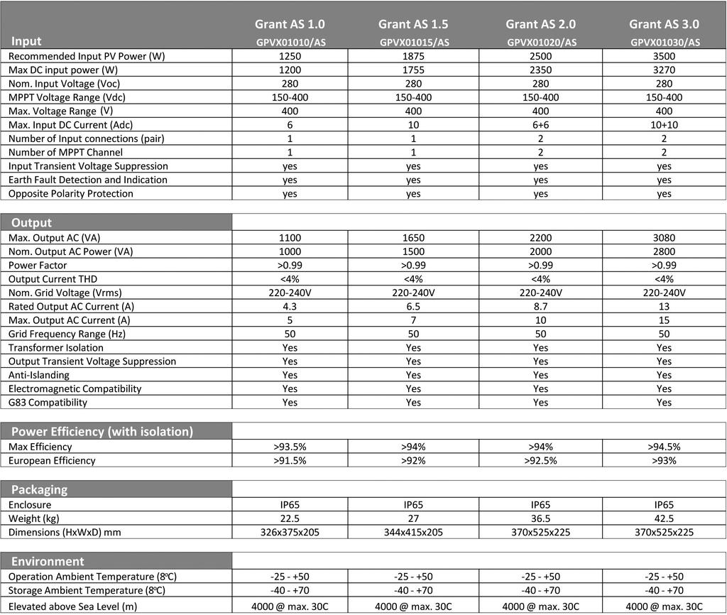
5 2.2 Technical Specification Product Information 5
6 3 System Design 3.1 Guidance Incorrect system design could cause damage to the inverter. Non-optimal design will lower the efficiency of the system and waste inverter power capacity. A guide matrix is provided below for each inverter model when using the Grant GPV180M Solar PV modules. CAUTION: On no account must these values be exceeded. System Design 6
 The inverter is installed on a concrete or brick wall. 3) The wall will not have a tilt angle greater than 30º. The inverter should be mounted a minimum of 1.2m from ground level.")
7 4 Installation 4.1 Siting The Grant range of inverters can be installed either indoors or outdoors. When siting the inverter, ensure that: 1) Sunlight cannot fall directly onto the inverter enclosure. 2) The inverter is installed on a concrete or brick wall. 3) The wall will not have a tilt angle greater than 30º. The inverter should be mounted a minimum of 1.2m from ground level. There must be a minimum space of 500mm above the top of the inverter and 200mm on both sides Figure 1. CAUTION: Do not install the inverter in an explosive or flammable environment. The site of the installation will be dry, clean from dust and sufficient room to allow free air to circulate. CAUTION: The site of the installation should not be an area that is in constant use by people or animals. Do not touch the enclosure while the inverter is in operation. The temperature of the casing may exceed 60ºC. Risk of burns. WARNING: The inverter must not be covered or partially covered at any time, due to risk of fire! Figure 1: Clearances around inverter, viewed from the front. Installation 7
 and hang on the top edge of the mounting plate.")
8 4 Installation continued Mounting Using the two holes on the mounting bracket as a guide, mark and drill two 12mm holes. Assemble the expansion bolt set as shown in Figure 2, and secure the mounting plate to the wall. Lift the inverter (with two people) and hang on the top edge of the mounting plate. Fix the positioning bolt to the bottom hole of the mounting bracket. Fasten the positioning bolt under the inverter. See Figure 3 WARNING: The inverter must not be installed on a flamable surface, due to risk of fire! 1) Mounting Bracket 2) Nut 3) Spring washer 4) Flat washer 5) Expansion tube 6) Bolt Figure 2: Bolt Assembly Installation Figure 3: Bolt Positioning 8
9 4.3 Electrical wiring Before connecting the AC and DC cables to the inverter, check the data plate on the inverter matches the installation requirements for both AC and DC. (Voltage, power, frequency, etc). Failure to do so could damage the inverter or cause a malfunction during operation. The Grant range of inverters are designed only for Solar PV Grid- Connected installations only. It is forbidden to connect this inverter to a public DC network or an island (battery) system. Only Grant Solar PV modules (GPV180M) are permitted to be fitted to this inverter. Do not connect any other type of DC generating device to this inverter. DC CONNECTION The length of the cable between the PV array and the inverter should not exceed 10m. This includes any DC isolators that are fitted between the array and the inverter. Longer cables could lower the overall system efficiency and could cause electromagnetic interference. * The inverter uses a MC Type4 DC plug and socket for connecting the PV array cables. * The cross section of the cable must not be less than 4mm². * The DC array cable must be rated for 1000VDC A C CONNECTION The flex used for each inverter is as follows: * For Grant AS1.0 and AS1.5 inverters, heat resistant 1.5mm² flex must be used. * For AS2.0 and AS3.0 inverters, heat resistant 2.5mm² flex must be used. The connection of the wires to the AC plug is shown on Figure 4. Figure 4: AC Plug Wiring diagram Installation 9
10 4 Installation continued Energising the system 4.5 De-energising the system CAUTION Check that the voltage of the completed PV string does not exceed 400V and note the polarity of the MC4 connectors is correct. Check the AC isolator(s) are in the off position and that there is no power being supplied to the inverter. Connect the AC plug to the inverter and screw the securing ring hand tight. Isolate the DC isolator(s). Connect the MC Type4 connecters to the inverter. Turn on the DC isolator(s). Note that the LCD display on the inverter reads Grid Volt Error Grid Frequency Error. Turn on the AC isolator(s). The inverter now takes approximately 1 minute to carry out self-diagnostic checks on the DC and AC conditions. Check the operation status by scrolling through the LCD displays one by one. Make sure the system is now in normal operation mode. For references to the LCD display see section 4. Irrespective what condition the inverter is in, carry out the following instructions In the order they appear to safely isolate the inverter. Turn off and lock off the DC isolator(s). Turn off and lock off the AC isolator(s). If maintenance on the DC side is required, disconnect the DC MC Type4 plugs from the inverter. If maintenance on the AC side of the inverter is required, disconnect the DC MC Type4 plugs and then disconnect the AC plug from the inverter. Installation 10
, otherwise it is unlit.")
11 5 Inverter Display and Indicators 5.1 LED indicators As shown in Figure 5, there are 3 indicator LED s on the front panel of the inverter. These LED s indicate Power, Run and Fault. When the system is energised, the power LED is lit (green), otherwise it is unlit. When the system is operating normally, and is generating power, the run LED is lit (green), otherwise it remains unlit. When the system develops a fault, the Fault LED lights one of two colours to indicate a fault. A Red LED indicates a category 1 fault; a green LED indicates a category 2 fault. When the fault is removed, this LED turns off. Figure 5: Indicator LED s 5.2 LCD Panel The LCD shows two lines of information. By touching the case of the inverter, the display will be backlit for a period of 30 seconds. The display screen can display 3 categories of information system initialisation; normal operation and system operating mode including the fault categories. When the system is energised, the LCD module will start Initialisation. See figure 6 for start sequence display. Figure 6: Start sequence display Inverter Display and indicators 11
12 5 Inverter Display and Indicators continued Normal operation Information of normal operation is split into groups of Operating Status; Statistical Information and Operating Mode Information. The Operating status is used to display the main operating parameters of the inverter. The Statistical Information parameter shows total operating time, daily generation and total power generation. The information is displayed on a rolling mode with an interval of 5 seconds. When the system is powered on, the LCD module begins initialising and will show a display similar to Figure 7. Figure 7: Display After a few seconds, the system will enter the rolling sequence of operating information. See Figure 8: Vgrid: Value range 0 to 499 V (volts) Pout: Value range 0 to 9999 W (Watts) For 2-string inverters where only one string is used, the unused channel may show a small residual voltage. This is normal. See Figure 9 Vpv1 (Voltage of PV string 1) Value range 0 to 499V (volts) Vpv2 (Voltage of PV string 2) Value range 0 to 499V (volts) Figure 8: Display Figure 9: Display See Figure 10. E-Today (Power generated today) in kwh Range: 0 to 99.9 kwh E-Total (Power generated in total) in kwh Range: 0 to 300,000 kwh Figure 10: Display See Figure 11. T-Today (generation time today) Range: 0.0 to 24.0 h (hours) T-Total (Total generation time) Range: 0.0 to 99,999 h (hours) Figure 11: Display Inverter Display and indicators Internal Temp of the Inverter See Figure 12. Value: 0 to 99 C Mode is used to indicate what operating mode the inverter Is currently in. Display real time: Year/Month/Date/Hour/Minute See Figure 13. Figure 12: Display 12 Figure 13: Display
 INTERRUPTED MODE The system has shut down because of CAT 1 (see info below). See Figure 15.")
13 5.4 System operating modes There are 4 operating modes as follows: 1) STAND-BY MODE The system is energised but hasn t met the requirements to generate power (too little sunlight/small DC voltage) or the equipment has not entered generation status after restart. See Figure 14. Figure 14: Stand-by mode 2) INTERRUPTED MODE The system has shut down because of CAT 1 (see info below). See Figure 15. Figure 15: Interrupted mode 3) POWER-LIMITING MODE The system reduces power output when overheated or Overloaded. See Figure 16. Figure 16: Power-limiting mode 4) MAXIMUM POWER POINT MODE The system is operating at maximum power See Figure 17. Figure 17 Maximum power point mode Inverter Display and indicators 13

14 5 Inverter Display and Indicators continued Fault Displays Faults are divided into 2 categories. CAT1 and CAT2. CAT1 Fault There are 5 types of fault: 1. BIT Failure 2. Ground Failure 3. PV1 Over Voltage 4. PV2 Over Voltage 5. System Error Figure 18: CAT1 Display The system will restore normal operating after the CAT1 fault is cleared. If this fault continuously occurs, the system Will shut down and will require the complete system to be examined by a qualified engineer. CAT2 Fault There are 5 types of fault: 1. PV over Power 2. Grid Volt Error 3. Grid Frequency Error 4. TVS1 Failure 5. TVS2 Failure There will be 2 lines of information displayed. The top line will display the fault information. Figure 19: CAT2 Display If there is more than one fault, the display will roll with intervals of 5 seconds. The bottom line will display information of the operating status and statistics. The display will roll with intervals of 5 seconds. If faults 1, 4 or 5 occur, the system will operate normally but it is advised that all TVS are replaced as soon as possible by a qualified engineer. If faults 2 or 3 occur the system will stop operating. The system will start automatically if the grid connection returns to a normal condition. Inverter Display and indicators 14
15 Grid Volt Error Pout: Range 0 to 3999W Figure 20: CAT2 Display Grid Volt Error Vpv1: Range 0 to 499V Figure 21: CAT2 Display Grid Volt Error Vpv2: Range 0 to 499V Figure 22: CAT2 Display Grid Volt Error E-Today: Range 0.0 to 99.9kWh Figure 23: CAT2 Display Grid Volt Error E-Total: Range 0 to 300,000 kwh Figure 24: CAT2 Display Grid Volt Error T-Total: Range 0.0 to 24.0h Figure 25: CAT2 Display Grid Volt Error Internal Temp: Range 0 to 99C Figure 26: CAT2 Display 5.6 Power Generation Data in addition to the system operating condition, the inverter also records power output for all conditions including daily output for the last 30 days and monthly outputs for the last 12 months. The system can record up to 1000 records offault information which includes fault characters to a maximum of 10 digits. When the records exceed 1000, the oldestrecord will be replaced.all of the above operating information and records can be read via the optional communication kit. Inverter Display and indicators 15
 Check supply voltages to consumer unit 2) Check frequency of power supply at consumer unit 3) Check compatibility of inverter for power supply being used. 6.")
16 6 Fault finding 6.1 Grid Volt Error Possible causes: 1) Grid supply is under or over voltage. 2) Grid frequency is lower/higher than allowed 3) Grid connection error (no Live and/or Neutral). Solutions: 1) Check supply voltages to consumer unit 2) Check frequency of power supply at consumer unit 3) Check compatibility of inverter for power supply being used. 6.3 DC Supply Issue Possible causes: 1) DC input over or under Voltage Solutions: 1) Isolate the inverter and check the Strings for over/under voltage. 2)Check this measurement with the aid of an irradiance meter. (Optional equipment from Grant Engineering.) WARNING There are no user-serviceable components inside the Grant grid connected inverter. Service and repair of the unit can only be carried out by Grant Engineering or a trained Grant representative, due to a high risk of electric shock! 6.2 TVS/Over Power Possible causes: 1) TVS component failure 2) System Overload Solutions: 1) Contact Grant Engineering Service department to arrange for the replacement of the TVS components when the display reads TVS1 or TVS2 failure. 2) If the display reads PV Over Power, check the PV configuration and check for inverter compatibility. 6.4 Inverter Defect Possible causes: 1) Internal errors including power components, over power condition, other system errors. Solutions: 1) Turn DC isolators off, turn AC isolators off and wait for 10 minutes. Check AC voltage supply and if all is well, restart the inverter normally. 2) If the systems fails to operate normally, shut down the system and contact the system installer. Fault Finding 16
17 7 Warranty information 7.1 Grant Grid Connected Inverter Warranty Dear Customer This product is guaranteed for ten years from the Date of Purchase (subject to the terms and conditions stated below). On completion of the installation, the system should be commissioned and registered online at: Breakdown during the Manufacturer s warranty. If your Grant Solar PV Grid Inverter should fail within the first ten years* of the date of purchase you must contact Grant Engineering (UK) Limited, who will arrange for the repair under the terms of their Warranty, providing that the inverter has been correctly installed and commissioned, and the fault is not due to misuse, or the failure of any system components not supplied by Grant UK (e.g. circuit breakers, AC cabling, etc.), any fault in the existing electrical installation or the incorrect setting of the system controls. Chargeable repairs A charge will be made if the cause of the breakdown is due to any of the following: The inverter has been installed for over ten years The inverter is damaged by improper installation, usage, connection. The inverter has not been installed in accordance with the manufacturers installation instructions. The inverter has been changed, modified or repair attempts have been made by unauthorised personnel The inverter has been damaged in transit Where the inverter data plate is missing or has been tampered with Where unauthorised accessories have been used Incorrect PV system design resulting in Over Voltage or Over Power. Force Majeure lightning, earthquake, flood, fire etc.* Terms of manufacturer s guarantee The Grant Solar PV Grid Inverter guarantee starts from the date of purchase. This guarantee does not cover breakdowns caused by incorrect installation, neglect, misuse, accident or failure to operate the system in accordance with these Installation and User Instructions. The online registration must be completed within thirty days of installation. Failure to do so does not affect your statutoryrights. The Grant Solar PV System must be installed by a competent installer in accordance with the relevant Codes of Practice, Regulations and Legislation in force at the time of installation. The Grant Solar PV Inverter components must not have been modified or tampered with. The installation is checked by a qualified electrician every ten years, or sooner, as required by the current BS.7671 (WiringRegulations 17th Edition). All claims under this guarantee must be made to Grant Engineering (UK) Ltd prior to any work being undertaken. Proof of purchase and date of installation must be provided on request. Invoices for call out/repair work by any third party will not be accepted unless previously authorisedby Grant Engineering (UK) Ltd. This guarantee is transferable providing the installation is serviced prior to the dwelling s new owners taking up residence.grant Engineering (UK) Ltd must be informed of the new owner s details. Grant Engineering (UK) Ltd will endeavour to provide prompt service in the unlikely event of a problem occurring, but cannot beheld responsible for any consequence of delay however caused. This guarantee applies to Grant Solar PV Inverters installed on the UK mainland, Isle of Man and Channel Islands only. Provision of inwarranty cover elsewhere in the UK is subject to agreement with Grant Engineering (UK) Ltd. Warranty Information 17
18 Notes Notes 18
19 Notes Notes 20
20 GRANT ENGINEERING (UK) LTD Hopton House, Hopton Industrial Estate, Devizes, Wiltshire. SN10 2EU Telephone: Fax: Website:
Grant Vortex Mag One. Magnetic Central Heating Filter. Installation and Servicing Instructions
 Grant Vortex Mag One Magnetic Central Heating Filter Installation and Servicing Instructions UK - DOC98 Rev 1.1 - October 2015 Contents 1 General 3 1.1 Introduction 3 1.2 How a Magnetic Filter Works 3
ADDENDUM to INSTALLATION INSTRUCTIONS for Grant Solar Pump Station
 ADDENDUM to INSTALLATION INSTRUCTIONS for Grant Solar Pump Station DOC.96-05/01 Rev01 - May 2015 ATTENTION INSTALLERS - UPDATED INFORMATION! There has been a recent change to the Grant Solar Thermal System
Solar Thermal. Grant Solar Pump Station Installation & Servicing Instructions
 Solar Thermal Grant Solar Pump Station Installation & Servicing Instructions Part No. DOC 96. Rev 02. October 2012 Important Note Important Note for Installers The Pump Station supplied with your Grant
Grant Vortex Mag One. Universal Magnetic Central Heating Filter. Installation and Servicing Instructions
 Grant Vortex Mag One Universal Magnetic Central Heating Filter Installation and Servicing Instructions UK DOC 0098 Rev 2.0 October 2017 Important Note for Installers These instructions are intended to
Manual. BlueSolar Grid Inverter 1500 / / / / / 230
 Manual EN BlueSolar Grid Inverter 1500 / 230 2000 / 230 2800 / 230 4000 / 230 5000 / 230 Before you start This manual contains important information regarding installation and safe operation of this unit.
Wind Power Inverter WINDY BOY 5000A/6000A
 Wind Power Inverter WINDY BOY 5000A/6000A User Manual WB5A-6A-BA-BEN114530 TBEN-WB50-60A Version 3.0 EN SMA Solar Technology AG Table of Contents Table of Contents 1 Information on this Manual.........................
STONESTAR AUSTRALIA PTY LTD
 42 48 REDWOOD DRIVER,DINGLEY VIC3172,AUSTRALIA TEL:0061 3 95518393 FAX:0061 3 95580776 EMAIL:stonestar@ssawheels.com.au Contents 1. Product Introduction... 3 2. Installation... 5 1) Safety instructions...
MAKING MODERN LIVING POSSIBLE. UniLynx Indoor Installation Manual. ULX 1800i ULX 3000i ULX 3600i ULX 5400i SOLAR INVERTERS
 MAKING MODERN LIVING POSSIBLE UniLynx Indoor Installation Manual ULX 1800i ULX 3000i ULX 3600i ULX 5400i SOLAR INVERTERS Contents Contents 1. Introduction 2 Introduction 2 Installation Sequence 2 Important
LED Emergency Luminaires
 LED Emergency Luminaires THIS FITTING SHOULD NOT BE USED IN AREAS EXCEEDING 25 C AMBIENT AIR TEMPERATURE This fitting must be installed by a qualified electrician and wired in accordance with the latest
YSmart Technology Co., Ltd. User Manual. GTI Grid Series. GTI Series Inverters for Grid-connected PV system
 YSmart Technology Co., Ltd. User Manual Contact Us Address: No. 30 XinFeng Road,Potoubei Village,Ailian Town,Longgang Dist, Shenzhen 51872,P.R. China Tel: (86)755-85232255 Fax: (86)755-85232255 Email :
Accessories for Wind Power Inverter WINDY BOY PROTECTION BOX 400 / 500 / 600
 Accessories for Wind Power Inverter WINDY BOY PROTECTION BOX 400 / 500 / 600 Installation Guide WBP-Box-IEN103320 IMEN-WBP-BOX Version 2.0 EN SMA Solar Technology AG Table of Contents Table of Contents
LIGHTNING PROTECTION UNIT (LPU)
") LIGHTNING PROTECTION UNIT (LPU) Photovoltaic Lightning Protection Device Installation and Operation Manual SPECIALTY CONCEPTS, INC. 8954 Mason Ave. Chatsworth, CA 91311 USA MODELS COVERED: LPU-50, LPU-150,
LIGHTNING PROTECTION UNIT (LPU) Photovoltaic Lightning Protection Device Installation and Operation Manual SPECIALTY CONCEPTS, INC. 8954 Mason Ave. Chatsworth, CA 91311 USA MODELS COVERED: LPU-50, LPU-150,
USER MANUAL MODEL: 3SPC3.3/106-D72/1100
 3inch Centrifugal Solar Submersible Pump USER MANUAL MODEL: 3SPC3.3/106-D72/1100 CONTENTS # Notes for Safe Operation... 3 1 How It Works... 4 2 3SPC3.3/106-D72/1100 Pump Description... 5 2.1 Model Instruction...
10A / 15A / 20A Solar Charge Controller. PU1024 / PU1524 / PU2024 series INSTRUCTION MANUAL
 10A / 15A / 20A Solar Charge Controller PU1024 / PU1524 / PU2024 series INSTRUCTION MANUAL Dear Customer, Thank you very much for choosing our product. This manual contains important information about
12/24 VOLT AUTOMATIC SOLAR CHARGE CONTROLLER
 12/24 VOLT AUTOMATIC SOLAR CHARGE CONTROLLER P/No.s SC320 & SC330 WARNING Please read these instructions completely prior to installation. Lead acid batteries can be dangerous. Ensure no sparks or flames
EdgeLED TM Range. Installation and Operating Instructions EdgeLED TM E1, E7, S1 and S7 Recessed Ceiling Luminaires
 EdgeLED TM Range THIS FITTING SHOULD NOT BE USED IN AREAS EXCEEDING 25 C AMBIENT AIR TEMPERATURE This fitting must be installed by a qualified electrician and wired in accordance with the latest edition
GEatom306KHF-5U Three-phase Grid-Tied Battery Inverter. Version 1.1. Global Mainstream Dynamic Energy Technology Ltd. 1
 GEatom306KHF-5U Three-phase Grid-Tied Battery Inverter Version 1.1 Global Mainstream Dynamic Energy Technology Ltd. 1 Content Prelude... 4 1. Safety... 5 1.1 How to Use This Manual... 5 1.2 Safety Rules...
HOYMILES MICRO-IVERTER MI-250
 HOYMILES MICRO-IVERTER MI-250 TECHNICAL MANUAL CONTENTS INTRODUCTION... 3 SAFETY... 4 SYMBOL ILLUSTRATION... 4 INSTALLATION WARNINGS... 5 PREPARE FOR INSTALLING... 6 TRANSPORT AND INSPECT... 6 CHECK INSTALLATION
English. Instruction and operation manual S 110. Power Meter
 English Instruction and operation manual S 110 Power Meter Dear Customer, thank you for choosing our product. The operating instructions must be read in full and carefully observed before starting up the
User Manual. Solar Charge Controller 3KW
 User Manual Solar Charge Controller 3KW 1 CONTENTS 1 ABOUT THIS MANUAL... 3 1.1 Purpose... 3 1.2 Scope... 3 1.3 SAFETY INSTRUCTIONS... 3 2 INTRODUCTION... 4 2.1 Features... 4 2.2 Product Overview... 5
HANGKAI GROUP HOYMILES MICRO-INVERTER MI-250
 HANGKAI GROUP HOYMILES MICRO-INVERTER MI-250 TECHNICAL MANUAL CONTENTS INTRODUCTION... 3 SAFETY... 4 SYMBOL ILLUSTRATION... 4 INSTALLATION WARNINGS... 6 PREPARE FOR INSTALLING... 7 TRANSPORT AND INSPECT...
EdgeLED TM Range. Installation and Operating Instructions EdgeLED TM RANGE INSTALLATION NON-EMERGENCY LUMINAIRES PRE INSTALLATION
 EdgeLED TM Range THIS FITTING SHOULD NOT BE USED IN AREAS EXCEEDING 25 C AMBIENT AIR TEMPERATURE This fitting must be installed by a qualified electrician and wired in accordance with the latest edition
7 MODES OF OPERATION INVERTER STATUS Standby: The PV string can only provide just enough voltage to minimum requirements of the controller.
 7 MODES OF OPERATION INVERTER STATUS 8 There are 3 different modes of operation. 7. Normal mode In this mode, Inverter works normally. Whenever the supplied power from PV panel is sufficient (voltage>50vdc),
T Series (N6052T) Solar Battery Hybrid System. Installation Manual Version 1.1
 Solar Battery Hybrid System. Installation Manual Version 1.1") T Series (N6052T) Solar Battery Hybrid System Installation Manual Version 1.1 Content 1. Safety... 1 1.1 How to Use This Manual... 1 1.2 Safety Rules... 1 1.3 Warning Notices Affixed to the Device... 2
T Series (N6052T) Solar Battery Hybrid System Installation Manual Version 1.1 Content 1. Safety... 1 1.1 How to Use This Manual... 1 1.2 Safety Rules... 1 1.3 Warning Notices Affixed to the Device... 2
Guidance to Installers of Viridian EV Charging Stations
 Guidance to Installers of Viridian EV Charging Stations Iss 6 - Jul 2016 Page 2 of 9 This guide is intended to instruct in the proper installation of a Viridian EV Charging Station. Please note that when
User Manual. SUN FLUX II Hot Water Controller. Model SEI 02. Off Grid/Hybrid PV Solar Hot Water Controller -1-
 User Manual SUN FLUX II Hot Water Controller Model SEI 02 Off Grid/Hybrid PV Solar Hot Water Controller -1- WARNING! Before using the equipment/installing, you need to read all safety instructions. General
CPS Energy Balancer. Version: 1.0
 CPS Energy Balancer Version: 1.0 CHINT POWER SYSTEMS AMERICA CO., LTD. Address: 700 International Parkway, Suite 102 Richardson, Texas Zip Code: 75081 Web: www.chintpower.com/na Email: americasales@chintpower.com
SUBMERSIBLE WATER PUMP
 SUBMERSIBLE WATER PUMP MODEL NO: CSV1A, CSV2A PART NO: 7230582, 7230602 OPERATION & MAINTENANCE INSTRUCTIONS ORIGINAL INSTRUCTIONS 05/14 iss 4 INTRODUCTION Thank you for purchasing this CLARKE Submersible
FREQUENCY INVERTER INSTALLATION & USER GUIDE
 En FREQUENCY INVERTER INSTALLATION & USER GUIDE Thank you for purchasing our frequency inverter. Please read the manual carefully before installing or using it and keep it for future reference after installation.
SCC-MPPT Solar Charge Controller
 Table 4: Alarm point for low battery voltage table Model Alarm point SCC-MPPT-300 10.5 V SCC-MPPT-600 21.0 V Table 5: Charging hour table for reference Battery Capacity To 90% capacity @ 25A charging current
DALI 650mA LED Driver
 Installation Guide DGLC650C18DD PATENT PENDING REGISTERED DESIGN Designed in Australia to meet Australian Standards and installation conditions DIGINET.NET.AU Diginet Control Systems Pty Ltd ABN 89 095
Pro Booster 802Li. Please read and fully understand the instructions in this manual before operation. Keep this manual safe for future reference.
 Please dispose of packaging for the product in a responsible manner. It is suitable for recycling. Help to protect the environment, take the packaging to the local amenity tip and place into the appropriate
My Reserve 500 Install Guide
 My Reserve 500 Install Guide System Overview Diagram Warnings Disclaimer of Liability and Warranty: This guide does not replace the Owner s Guide and Installation Instructions supplied with the components.
Operating instructions. sonnenprotect for operators. KD-337 Part no Version X00.
 Operating instructions for operators sonnenprotect 1300 KD-337 Part no. 22010 Version X00 info@sonnenbatterie.de www.sonnenbatterie.de EN IMPORTANT Read this documentation carefully before operation. Retain
Doc Ref: WD024/2/11/12 Fern-Howard Ltd. 2 Newman Lane, Alton, Hampshire, GU34 2QR. Reg. No
 The Galileo II range of decorative, wall or ceiling mounted luminaires, are as versatile as they are attractive. The range is available in two body sizes, 350mm and 425mm diameter, and in a variety of
Solar Charge Controller
 Table 3: Charging voltage for 4 types of battery Battery Type Battery Type Code SC-600W MPPT Bulk Voltage Floating Voltage Vented 01 28.6 V 26.4 V Sealed 02 28.6 V 26.8 V Gel 03 28.6 V 27.4 V NiCd 04 28.6
Megohmmeter Test Probe
 Megohmmeter Test Probe User Manual ENGLISH www.aemc.com CHAUVIN ARNOUX GROUP Copyright Chauvin Arnoux, Inc. d.b.a. AEMC Instruments. All rights reserved. No part of this documentation may be reproduced
Operating Instructions
 Operating Instructions Ex UPS Combination of > 8265/5 GUBox control panel > 8316 battery box Contents 1 Contents 1 Contents 2 2 General Information 2 3 Safety Instructions 2 4 Conformity to standards 3
MANUFACTURED IN THE UK
 The Galileo II range of decorative, wall or ceiling mounted luminaires, are as versatile as they are attractive. The range is available in two body sizes, 350mm and 425mm diameter, and in a variety of
PV inverter SUNNY MINI CENTRAL 7000HV
 PV inverter SUNNY MINI CENTRAL 7000HV User Manual SMC70HV11-BA-BEN112930 TBEN-SMC70HV Version 3.0 EN SMA Solar Technology AG Table of Contents Table of Contents 1 Information on this Manual.........................
OPERATION INSTRUCTIONS
 www.r-techwelding.co.uk Email: sales@r-techwelding.co.uk Tel: 01452 733933 Fax: 01452 733939 ProArc 175 INVERTER ARC WELDER OPERATION INSTRUCTIONS Version 2017-10 2 3 Thank you for selecting the R-Tech
MAINTAINED LED DOUBLE SIDED SUSPENDED CEILING MOUNTED EMERGENCY LIGHT
 Model No. PEL00580 MAINTAINED LED DOUBLE SIDED SUSPENDED CEILING MOUNTED EMERGENCY LIGHT 1 Please read these instructions carefully before starting installation and retain for future reference. The centre
SUBMERSIBLE DIRTY WATER PUMP
 FOR USE WITH A 110V SUPPLY ONLY SUBMERSIBLE DIRTY WATER PUMP MODEL NO: DWP210A PART NO: 7230102 OPERATION & MAINTENANCE INSTRUCTIONS LS0115 INTRODUCTION Thank you for purchasing this CLARKE Submersible
LS1024BP/ LS2024BP. Solar Charge Controller USER MANUAL
 EPSOLAR LS1024BP/ LS2024BP Solar Charge Controller USER MANUAL Thank you very much for selecting our product! This manual offers important information and suggestions with respect to installation, use
DC-DC STEP DOWN CONVERTER CV 24/12V - 15 A Pro
 User s Manual DC-DC STEP DOWN CONVERTER CV 24/12V - 15 A Pro ACMA115 INTRODUCTION Thank you for choosing a PRESIDENT product. You can be sure that the product you have purchased is one of the best that
SCC-MPPT Solar Charge Controller
 Table 3: Charging voltage for 4 types of battery Battery Battery 12V battery system 24V battery system Type Type Code Bulk Floating Bulk Floating Vented 01 14.3 V 13.2 V 28.6 V 26.4 V Sealed 02 14.3 V
2.0Ah BATTERY INSTRUCTION MANUAL
 BATTERY SAFETY WARNINGS THIS MANUAL CONTAINS IMPORTANT SAFETY AND OPERATING INSTRUCTIONS FOR YOUR BATTERY. 2.0Ah BATTERY INSTRUCTION MANUAL SPECIFICATIONS Input: Battery Capacity: Power Consumption: Weight:
SCC-MPPT Solar Charge Controller
 Solar Charge Controller Quick Guide 200W 300W 400W 600W 850W V. 2.2 1. Introduction solar charge controller uses PWM-based DSP controller to keep the batteries regulated and prevent batteries from overcharging
1000mA - 650mA Phase Dimmable LED Driver
 Installation Guide DGLC1000C25PD 1000mA - 650mA Phase Dimmable LED Driver PATENT PENDING REGISTERED DESIGN Designed in Australia to meet Australian Standards and installation conditions DIGINET.NET.AU
User Manual Solar Charge Controller 3KW
 User Manual Solar Charge Controller 3KW Version: 1.3 CONTENTS 1 ABOUT THIS MANUAL... 1 1.1 Purpose... 1 1.2 Scope... 1 1.3 SAFETY INSTRUCTIONS... 1 2 INTRODUCTION... 2 2.1 Features... 2 2.2 Product Overview...
Dycon D1532SM. EN50131/PD6662 Grade 3, 12V 2A Power Supply. Technical Description Installation and Operating Manual DYCON POWER SOLUTIONS LTD
 Dycon D1532SM EN50131/PD6662 Grade 3, 12V 2A Power Supply Technical Description Installation and Operating Manual DYCON POWER SOLUTIONS LTD Tel: +44 (0)1443 471 900 Unit A Cwm Cynon Business Park Mountain
The following lighting types are NOT compatible with the TT- 402Wireless Inline Dimmers:
 TT402 (300W) Incandescent Wireless receiver Inline Dimmer Product Description The TT- 402is a 40-300W dimmable wireless receiver. It can be paired with only circuits 1 and 2 (keys 4 or 5) on the Taptile
Reviewed: DD Month University Code of Practice for Electrical Safety. PART B - Design and Construction of Electrical Equipment within the University
 Safety Office Reviewed: 17 July 2012 Reviewed: DD Month University Code of Practice for Electrical Safety PART B - Design and Construction of Electrical Equipment within the University The purpose of this
Dycon D2430 EN54-4 Fire Alarm Power Supply Series
 Dycon D2430 EN54-4 Fire Alarm Power Supply Series Technical Description Installation and Operating Manual Construction Product Regulation 0359-CPR-00434 Page 1 of 14 Contents 1. General... 3 1.1 Product
MOdel No: MM19.V3 WARNING CAUTION 1. SAFETY INSTRUCTIONS
 Instructions for: Digital Multimeter - 6 Function MOdel No: MM19.V3 Thank you for purchasing a Sealey product. Manufactured to a high standard this product will, if used according to these instructions
IES GRID FEED-IN LIMITER
 IES GRID FEED-IN LIMITER Installation and User Manual Models SPS01101-ABB SPS01303-ABB CONTAINS IMPORTANT INSTALLATION AND TESTING PROCEDURES THAT MUST BE FOLLOWED TO ENSURE COMPLIANCE WITH ENERGEX AND
Pure Sine Wave Inverter GP-HS1500. Owner s Manual
 Pure Sine Wave Inverter GP-HS1500 Owner s Manual 2 Table of Contents Introduction 3 Specifications 4 Name and Main Function 5 Installation 7 Operation 9 Operating Limits 13 Troubleshooting 13 Maintenance
OPERATION & MAINTENANCE INSTRUCTIONS
 400W SUBMERSIBLE PUMP WITH FOLDING BASE AND FLOAT SWITCH MODEL NO: PSV6A PART NO: 7230695 OPERATION & MAINTENANCE INSTRUCTIONS LS0315 INTRODUCTION Thank you for purchasing this CLARKE 400W Submersible
Installation and operating instructions. Solar charge controller MPPT 10 A / 20 A Z Z
 Installation and operating instructions Solar charge controller MPPT 10 A / 20 A EN 1 Contents 1. About these instructions... 3 1.1 Applicability... 3 1.2 Users... 3 1.3 Description of symbols... 3 2.
Installation manual portable distributors
 EN Installation manual portable distributors EN 60003206 Issue 11.2016 15/11/2016 Table of contents 1 About this manual 3 1.1 Structure of the warnings 3 1.2 Symbols used 4 1.3 Signal words used 4 2 Intended
SOLAR LIGHTING CONTROLLER SUNLIGHT MODELS INCLUDED IN THIS MANUAL SL-10 SL-10-24V SL-20 SL-20-24V
 SOLAR LIGHTING CONTROLLER OPERATOR S MANUAL SUNLIGHT MODELS INCLUDED IN THIS MANUAL SL-10 SL-10-24V SL-20 SL-20-24V 10A / 12V 10A / 24V 20A / 12V 20A / 24V 1098 Washington Crossing Road Washington Crossing,
MANUFACTURED IN THE UK
 The Trojan range of energy efficient bulkhead fittings are manufactured with a polycarbonate base and diffuser. Together with a poured gasket the Trojan leads vandal-resistant IP65 technology. With a hinged
Instruction Manual PC104/PC105 3-PHASE SOCKET TESTER. Check out what else you can get from Martindale:
 Check out what else you can get from Martindale: 17th Edition Testers Accessories Calibration Equipment Continuity Testers Electricians Kits Environmental Products Full Calibration & Repair Service Fuse
2D products are warranted for one year, the expected life of the ballast and/or Emergency module is 5 years
 2D products are warranted for one year, the expected life of the ballast and/or Emergency module is 5 years The Trojan range of energy efficient bulkhead fittings are manufactured with a polycarbonate
5 IN 1 JUMP START OPERATION & MAINTENANCE INSTRUCTIONS MODEL NO: JS5IN1 PART NO: LS0810
 5 IN 1 JUMP START MODEL NO: JS5IN1 PART NO: 6240005 OPERATION & MAINTENANCE INSTRUCTIONS LS0810 INTRODUCTION Thank you for purchasing this CLARKE product. Before attempting to use this product, please
IQL Helios Area-/Streetlight. User Manual
 Contents 1. Safety... 3 2. Warranty... 3 2.1 General... 3 2.2 Life span... 3 3. Type plate... 4 4. Product Description... 5 5. Specifications... 6 5.1 General... 6 5.2 Dimensions... 6 6. Installation...
SMART ENERGY SAVER Manual
 SMART ENERGY SAVER Manual PLEASE READ CAREFULLY BEFORE INSTALLING OR USING SMART ENERGY SAVER. THIS UNIT SHOULD ONLY BE INSTALLED AS SUPPLIED (AS A PLUG AND PLAY UNIT) IF YOU HAVE PURCHASED THE HARD WIRED
OPERATION & MAINTENANCE INSTRUCTIONS
 750W SUBMERSIBLE PUMP WITH BUILT-IN FLOAT SWITCH MODEL NO: PSV5A PART NO: 7236046 OPERATION & MAINTENANCE INSTRUCTIONS ORIGINAL INSTRUCTIONS LS0917 iss 3 INTRODUCTION Thank you for purchasing this CLARKE
Advanced Hybrid Wind / Solar Charge Controller. User Manual
 Advanced Hybrid Wind / Solar Charge Controller User Manual Safety 1. Please read the instructions carefully prior to product use or installation and refer back to them throughout the installation. 2. This
Accessories for Stand-alone inverter SUNNY ISLAND GENMAN
 Accessories for Stand-alone inverter SUNNY ISLAND GENMAN Technical Description GenMan-TEN082730 98-2001230 Version 3.0 EN SMA Solar Technology AG Table of Contents Table of Contents 1 Notes on this manual..............................
400 Watt Backup Power System Owner s Manual
 400 Watt Backup Power System Owner s Manual WARNING: Read carefully and understand all ASSEMBLY AND OPERATION INSTRUCTIONS before operating. Failure to follow the safety rules and other basic safety precautions
Pan and Tilt Head CDD2416-T
 Pan and Tilt Head CDD2416-T Installation guide Before attempting to connect or operate this product, please read these instructions completely Williams Electronics Ltd www.w-e.co.uk Tel: +44 (0)2921 660
650mA Phase Dimmable LED Driver
 Installation Guide DGLC650C18PD PATENT PENDING REGISTERED DESIGN Designed in Australia to meet Australian Standards and installation conditions DIGINET.NET.AU Diginet Control Systems Pty Ltd ABN 89 095
KSZ 10B Current Probe Calibrator. Instruction Manual
 KSZ 10B Current Probe Calibrator Instruction Manual Copyright 2011 PMK GmbH All rights reserved. Information in this publication supersedes that in all previously published material. Specifications are
362 Clamp Meter. Users Manual
 362 Clamp Meter Users Manual PN 3622678 August 2010, Rev. 1, 4/13 2010, 2013 Fluke Corporation. All rights reserved. Printed in China. Specifications are subject to change without notice. All product names
Phoenix Inverter
 Manual EN Handleiding NL Manuel FR Anleitung DE Manual ES Appendix Phoenix Inverter 12 250 12 375 12 500 12 800 24 250 24 375 24 500 24 800 48 250 48 375 48 500 48 800 1. Safety instructions WARNING: ELECTRIC
Technical Requirements for Renewable Energy Power System
 Hotline: 2843 3228 Email address: RE@hkelectric.com Issued on 20 Nov 2018 1. Introduction 1.1. This document aims to provide the technical requirements for renewable energy power system (the REPS) connected
MICRO-INVERTER OMNIKSOL M-300
 MICRO-INVERTER OMNIKSOL M-300 TECHNICAL MANUAL CONTENTS INTRODUCTION... 3 SAFETY... 4 SYMBOL ILLUSTRATION... 4 INSTALLATION WARNINGS... 6 PREPARE FOR INSTALLING... 7 TRANSPORT AND INSPECT... 7 CHECK INSTALLATION
LED AC DRIVERLESS FLOODLIGHTS WITH PIR FOR MODEL: FLAC10BPIR, FLAC20BPIR, FLAC30BPIR & FLAC50BPIR
 INTRODUCTION The LED AC Driverless Floodlights with PIR include a hanging / mounting bracket and a 100cm cable. SPECIFICATION LED 800-4000lm IP65 180-240V IK07 6000K 50Hz >80 Ra 10W- 50W Dimensions: FLAC10BPIR:
Domestic Water Supply Pressure Pumps
 Domestic Water Supply Pressure Pumps Bianco Domestic Water Supply Pressure Pumps BIA-MULTI900PC BIA-MULTI1300 Instruction manual Safety precautions The symbol together with one of the following words Danger
USER MANUAL MPS 1-5KW SERIES
 USER MANUAL MPS 1-5KW SERIES Low Series Frequency Solar and Wind Power Charging Inverter CONTENTS 1 WWW.NEXTGENNRG.COM 1. Introduction... 3 2. Profile Structure 4 2.1. Working Principle 4 2.2.Product Features..5
250W PUDDLE PUMP WITH AUTO SENSOR MODEL NO: PSP105
 250W PUDDLE PUMP WITH AUTO SENSOR MODEL NO: PSP105 PART NO: 7230693 OPERATION & MAINTENANCE INSTRUCTIONS ORIGINAL INSTRUCTIONS LS0917 -- iss 3 INTRODUCTION Thank you for purchasing this CLARKE 250W Puddle
ACC Series Power Conditioner OPERATION & INSTALLATION MANUAL
 ACC Series Power Conditioner OPERATION & INSTALLATION MANUAL PHASETEC digital power conditioners are designed to safely operate electrical equipment in the harshest power quality environments. With a wide
MICROCARE 3 PHASE INVERTER MANUAL
 3 PHASE INVERTER MANUAL 1 Contents 1. INTRODUCTI... 3 2. SAFETY INSTRUCTI... 4 3. SYSTEM DESCRIPTI... 6 4. WIRING DIAGRAM... 9 5. INVERTER OPERATI... 10 6. INVERTER CLUSTER PROGRAMMING... 13 7. CLUSTER
RELAY BOX PRODUCT MANUAL IMPORTANT
 RELAY BOX PRODUCT MANUAL IMPORTANT Installer: This manual is the property of the customer and must be retained with the product for maintenance and operational purposes. 1 TABLE OF CONTENTS Page INTRODUCTION
SPI SS SPI SS Owners Manual
 SELECTRONIC AUSTRALIA SPI 200-12SS SPI 200-24SS Owners Manual Selectronic Australia Pty Ltd. 25 Holloway Drive, Bayswater, Victoria, 3153 Rev 1 SELECTRONIC AUSTRALIA SPI 200-12SS, SPI 200-24SS OWNERS MANUAL
SubDrive Inline Constant pressure controller Additional information for Australia, NZ TOLL FREE HELP 1300 FRANKLIN
 SubDrive Inline 1100 Constant pressure controller Additional information for Australia, NZ 1 TOLL FREE HELP 1300 FRANKLIN ! WARNING Serious or fatal electrical shock may result from failure to connect
Eazipole Cordless. Installation & Set Up Instructions. Electric Blinds & Curtains
 Eazipole Cordless Installation & Set Up Instructions Electric Blinds & Curtains Pole Installation - Deciding The Best Position Points to consider when planning the installation of your pole It may be easiest
BATTERY BOOSTER/CHARGER MODEL NO: DIGICAR 600
 BATTERY BOOSTER/CHARGER MODEL NO: DIGICAR 600 PART NO: 6261200 OPERATION & MAINTENANCE INSTRUCTIONS LS0815 INTRODUCTION Thank you for purchasing this CLARKE Battery booster / charger which is suitable
LEAD ACID BATTERY CHARGER
 LEAD ACID BATTERY CHARGER MODEL NO: LA4 & LA6 OPERATION & MAINTENANCE INSTRUCTIONS LS1214 INTRODUCTION Thank you for purchasing this CLARKE Battery Charger. Please read this manual thoroughly, before attempting
230VAC Power Inverter 400W Owner s Manual
 400W 230VAC Power Inverter 400W Owner s Manual For safe and optimum performance, the Enerdrive epower Inverter must be used properly. Carefully read and follow all instructions and guidelines in this manual
3KW Off-grid Solar Power System LFP Battery
 3KW Off-grid Solar Power System LFP Battery 1 CATALOGUE 1. S u m m a r y 3 2. T e c h n i c a l p a r a m e t e r 4 3. D i s p l a y a n d f u n c t i o n i n s t r u c t i o n 5 4. S e q u e n c e o f
The Power of Reliability INSTRUCTION MANUAL
 The Power of Reliability INSTRUCTION MANUAL SAFETY & WARNINGS Read this manual carefully and understand all Warnings and Cautions before connections are made to the Inverter. If unsure about any aspects
NON MAINTAINED TWIN SPOTLIGHT WALL MOUNT LED EMERGENCY LIGHT
 Model No. PEL00581 NON MAINTAINED TWIN SPOTLIGHT WALL MOUNT LED EMERGENCY LIGHT 1 Please read these instructions carefully before starting installation and retain for future reference. The centre page
i-energy i-micro inverter GT260
 i-energy i-micro inverter GT260 This installation guide contains important instructions on safety matters and the installation of the i-energy i-micro inverter GT260. Please read this guide carefully and
Heat Meter Integrator
 Heat Meter Integrator Features Simply operation Integral wall and DIN-rail mounting bracket Pulsed or M-Bus output options Measures heating or cooling and heat/cooling Specification Product Codes Temperature
NCSA 20plus Service Manual
 Adam Equipment NCSA 20plus Service Manual (P.N. 7.00.6.6.0247- Revision A - August 2012) Adam Equipment Company 2012 1.0 CONTENTS 1.0 CONTENTS...1 1.1 KEY AND PANEL DESCRIPTION...2 2.0 OPERATION...3 2.1
Operating instructions Solenoid interlock TKM/TKF. 1. About this document. Content
 1. About this document Operating instructions.............pages 1 to 6 Original 1.1 Function This operating instructions manual provides all the information you need for the mounting, set-up and commissioning
1000-Watt Energy Center
 1000-Watt Energy Center OPERATING INSTRUCTIONS Patent Pending Sierra Wave 1000-Watt Energy Center #9675 The Sierra Wave 1000-Watt Energy Center is a heavy duty and efficient portable power center offering
SMT. Installation and Operation Manual. Model:SMT WITH MPPT TECHNOLOGY
 SMT WITH MPPT TECHNOLOGY Installation and Operation Manual Model:SMT SMT Dimensions Specification Summary System Voltage 12 V/24V Rated Battery Current 12V, 5A 8A 10A 15A 20A 25A 24V, 5A 8A 10A 15A Rated