Power Suite Overview 9 Application Functionality 10. Explorers 10. My Profile - Setting Default Preferences 11. Pop-up Menu 12.
|
|
|
- Rachel Lester
- 6 years ago
- Views:
Transcription
1 Table of Contents Power Suite Overview 9 Application Functionality 10 Explorers 10 My Profile - Setting Default Preferences 11 Pop-up Menu 12 GenSize 13 GenSize Overview 13 Working with Projects 13 GenSize Dashboard 13 Import GenSize Project 14 Create New Project 15 Open Project 16 Project Parameters 18 Project Country 18 Transient Dip Limits 18 Delete Project 19 Copy Project 21 Save Project 22 Close Project 24 Sharing Projects 24 Follow these steps to share a project 25 GenSize Link to Library 27 Size Project 28 Edit Project 33 Default Preferences 33 Edit Project 34 Fuel 38 Emissions 38 Frequency 38 Generator Set Phase 38 Generator Sets Running in Parallel 39 Transient Dip Limits 39 Transient Dip Limits 39 Maximum Allowable Step Voltage Dip 40 Maximum Allowable Step Frequency Dip 40 Maximum Allowable Peak Voltage Dip 40 Maximum Allowable Peak Frequency Dip 41 Peak Voltage Dip Limits Calculation 41 Peak Frequency Dip Limits Calculation 41 Minimum Generator set Load Allowed, Percent of Rated Load 41 Maximum Generator set Load Allowed, Percent of Rated Load 41 Table of Contents Page 1
2 Site Conditions 42 Ambient Temperature 42 Altitude 42 Maximum Allowable Alternator Temp Rise 42 Temperature Rise at Full Rated Load 42 Voltage 43 Generator Set Duty Ratings 43 Duty 43 Generator Connected Load 43 Generator Nominal Power Rating Definitions 43 Generator Rated Load 44 Standby Rating 44 Prime Rating 45 Continuous Rating 45 Working with Loads 45 Loads Overview 45 Create New Load 49 Edit Load 50 Delete Load 51 Load Definitions 52 Generator Connected Load 52 Generator Rated Load 52 Harmonic Content (THDI%) 53 Leading Power Factor Load 53 Regenerative Loads 53 Non-linear Loads 54 Total Harmonic Voltage Distortion (THDV%, RMS) 54 Project Voltage Distortion Limit 55 Rectifier Types 55 Surge Loads 56 Voltage Unbalance 56 Load Starting and Running Requirements 56 Running Amps (RAmps) 56 Running kva (RkVA) 56 Running kw (RkW) 56 Running Power Factor (RPF) 56 SkVA 57 SkW 57 Starting Power Factor 57 Non-linear kva 57 Peak kw (PkW) 57 Peak kva (PkVA) 57 Types of Loads 58 Lighting Load 58 Entering Lighting Loads 58 Air Conditioning Load 61 Table of Contents Page 2
3 Entering Air Conditioning Loads 61 Air Conditioning Load Efficiency 70 Air Conditioning Load Calculations 71 Battery Charger Load 72 Entering Battery Charger Load 72 Medical Imaging Load 75 Entering Medical Imaging Load 75 Medical Imaging Voltage Dip Calculations 78 Peak Amperes 78 Peak kw (PkW) 78 Peak kva (PkVA) 78 Motor Load 79 Entering Motor Load 79 Motor Load Calculations 88 Three-Phase Starting Methods 89 High Efficiency NEMA Design B 90 Large Motor Loads (over 50 HP) 90 Cyclic Motor Load 91 Locked Rotor Kilovolt-Amperes Factor (LR-kVA / HP factor) 91 Low/High Inertia Motor Load 91 Motor Starting Voltage Dip 92 Nema Letter Code 92 Variable Speed Drives 94 Soft Ramp Options 94 Reduced Voltage Starting Methods 95 Single-Phase Motor Type 95 Solid State Starter Equipped With Bypass 95 Standard NEMA Design B, C, or D 95 IEC Motor 95 Fire Pump Load 96 Entering Fire Pump Load 96 Fire Pump Load Calculations 105 Fire Pump Code Requirements 105 UPS Load 107 Entering UPS Load 107 UPS Load Calculations 110 UPS Reverts to Battery during Transients 111 User Defined Load 112 Entering User Defined Load 112 Welding Load 115 Entering a Welding Type Load 115 Peak Amperes 117 Peak kw (PkW) 117 Peak kva (PkVA) 117 General Receptacle Load 118 Entering a General Receptacle Load 118 Table of Contents Page 3
4 Working with Load Steps 121 Load Steps Considerations 121 Add Loads into Steps 121 Move/Copy Loads Between Steps 123 Change Load Quantity 125 Add New Step 127 Edit Load Step 128 Set Number of Load Steps 129 Maximum Step kw (SkW) 130 Maximum Step kva (SkVA) 131 Moving Steps 131 Merging Steps 132 Delete Load in Step 135 Delete Step 136 Maximum Step Voltage Dip 137 Step Starting Calculations 137 Maximum Allowable Step Frequency Dip 138 View Loads and Steps 138 View Steps and Loads Details 138 Viewing Sizing Recommendations 138 View Generator Set Recommendations 138 View Selected Model Index Page 138 Reported Load and Generator set Parameters 139 Generator Set Parameters 139 Alternator Frame 139 Excitation 139 Permanent Magnet Generator (PMG) Excitation 139 Shunt Excitation 139 Extended Stack 139 Full Single-Phase Output Generator 139 Increased Motor Starting 139 Knee Point 140 Voltage Range 140 Reconnectable Generator 140 Load Parameters 140 Non-linear kva 140 Cumulative Step kva 140 Cumulative Step kw 140 Cumulative Surge kva 140 Cumulative Surge kw 140 Effective Step kw 140 Effective Step kva 140 Cumulative Step kw 140 Cumulative Step kva 140 Peak kw (PkW) 141 Peak kva (PkVA) 141 Table of Contents Page 4
5 Maximum Allowable Peak Voltage Dip 141 Maximum Allowable Peak Frequency Dip 141 Power Factor 141 Understanding GenSize Recommendations 141 Max. Step Voltage Dip 142 Max. Step Frequency Dip 142 Peak Voltage Dip 142 Peak Frequency Dip 143 Site Rated Standby/Prime/Continuous kw 143 Site Rated Alternator Max kw (Temperature Rise) 143 Site Rated Alternator Max kva (Temperature Rise) 143 Site Rated Max SkW and Max SkVA 145 Temperature Rise at Full Load 146 Excitation 146 THDV% Limit 146 Why a generator set may not be recommended 146 Working with Reports 147 Print Reports 147 Loads and Steps Detail Report 148 Steps and Dips Detail Report 150 Performance Definitions 152 Recommended Generator Report 152 Recommended Generator Report 152 Max. Step Voltage Dip 155 Max. Step Frequency Dip 155 Peak Voltage Dip 155 Peak Frequency Dip 155 Site Rated Alternator kva at Specified Temperature Rise 156 Site Rated Alternator kw at Specified Temperature Rise 156 Site Rated kw for Specified Duty 156 Site Rated Max SkW 157 Maximum Step Voltage Dip 158 Working with GenCalc Tools 158 Remote Radiator Ventilation Estimator 158 Imported Parameters From GenSize 158 Exhaust System Heat Radiation and Additional Heat Sources 158 Calculated Heat Emission Summary 158 Airflow Summary 158 Report 159 Remote Cooling Estimator 159 Imported Parameters From GenSize 159 User Input Jacket Water (JW) 159 User Input After Cooler (AC) 159 Calculated Fields 160 Report 160 Alternator Available Short Circuit Current Estimator 160 Table of Contents Page 5
6 Imported Generator Set Parameters 160 Short Circuit Current Summary 160 Report 160 Fuel Pipe Sizing Estimator 160 Fuel system configuration Diesel 161 Imported Parameters From GenSize Diesel 161 User Input Supply Line Diesel 161 User Input Return Line Diesel 161 Pressure Drop Summary Diesel 161 Imported Parameters From GenSize Rich Burn Natural Gas or Propane 162 Pressure Drop from Piping, Fittings, and Other Components Rich Burn Natural Gas or Propane 162 Pipe Sizing Summary Rich Burn Natural Gas or Propane 162 Report 162 Exhaust Backpressure Estimator 162 Imported Generator Set Parameters 162 Pressure Drop from Piping, Mufflers, Fittings and Other Components 162 Aftertreatment Sources 163 Aftertreatment Sources 163 Report 163 Frequently Asked Questions 164 Can I Enter Projects Created in Earlier Versions of Power Suite? 164 Do I Need to Limit Peak Voltage Dip for Fire Pumps? 164 Have All Loads Been Placed Into Steps? 164 How Current is the Data in GenSize? 164 How Do I Change the Quantity of Loads in a Step? 164 How Do I Enter a Transformer Load? 164 How Does GenSize Make Step Calculations? 165 How Much Time Should I Assume Between Each Load Step? 165 How to Get Started with New GenSize Project? 165 I Don't Want My Alternator Temperature Rise to Exceed 80 C. Why is a 125 C Rise Set Recommended? 165 Is There a Manual Available to Help me Learn How to Use GenSize? 166 What Does the Message "No Generator Set is Available That Meets Your Running Load Requirements" mean? 166 What Does the Message "No Generator Set is Available Which Meets Your Frequency or Voltage Dip Requirements" mean? 166 What is a Peak Surge? 166 Which Loads Are in Which Steps? 166 Why Does GenSize Allow Generator set Recommendations up to 100% of Nominal Rated Load? 167 Why Wasn't a Generator set Recommended? 167 GenSpec Projects 169 GenSpec Projects for Generator Sets 169 Create or Edit a Linked or Standalone Genset Project 169 Project Details 169 Project Conditions 170 Table of Contents Page 6
7 Certifications 170 Quality Assurance 170 Engine Generator Set 170 Engine 171 Fuel Oil Storage 171 Controls and Monitoring 171 Generator, Exciter, and Voltage Regulator 171 Outdoor Generator Set Enclosure 172 Service, Warranty, Training, and Testing 172 Save 172 Generate Spec 172 GenSpec Projects for ATS 172 Transfer Product - Create New or Edit Project Page 172 Project Parameters 172 Ratings 173 Transitions 173 Protective Relays (applicable to Closed Transition only) 174 Application Type 174 Voltage 174 Enclosure 175 Advanced Control Features 175 Optional Features 175 GenSpec Projects for Paralleling Systems 175 Paralleling Systems Create or Edit a Project 175 Project Parameters 175 Master Control System Configuration 176 HMI Options 176 Controller Options 177 Customer Interface 177 Switchgear Configuration 177 Access Options 178 Breaker Control Options 178 Protection Options 178 Options 178 Save 179 Generate Spec 179 System Topologies 179 Isolated Bus 179 Isolated Bus with Gen Main 180 Common Bus 181 Single Transfer Pair 182 Dual Transfer Pair 183 Main Tie Main Split Gen Bus 184 Main Tie Main Common Gen Bus 185 Table of Contents Page 7
8 Library 186 Library Overview 186 Batch Printing 186 Table of Contents Page 8
9 Power Suite Overview We are pleased to provide you with this update of Cummins Power Generation s Power Suite application. This update contains several new features and new tools to help you design our products into your power generation facilities. Power Suite is a software application that uses a single user interface for the multiple programs contained in the Suite. Each of these can be accessed directly and simultaneously. In addition, we have taken steps to integrate the individual applications. The GenSize tool uses a common product performance database and you can now open the Library in a separate window to select and view product documentation for generator set models. Power Suite now contains the following components: o o o GenSize with new GenCalc tools GenSpec for Generator Sets, Transfer Products, and Paralleling Systems Library We hope you are satisfied with Power Suite. If you have any problems or questions, please direct your inquiries to: powersuite@cummins.com Table of Contents Page 9

10 Application Functionality Explorers GenSize Explorer: The GenSize Explorer has a similar interface to Windows Explorer: The left side of the Explorer shows the entire project with all of its components. That section is called a Project tree view. It has expanding nodes and can be expanded by pressing the + box next to the node. Once it is expanded the box will show - to collapse the node. This will allow you to see the Project as a whole. You can also expand the tree view if you pick up the Project and select Expand Tree from the popup menu. To collapse the tree, select Collapse Tree from the pop-up menu. The right side of the Explorer shows the contents of a node selected on the left side. That section is called a list view. The list view can show more detail than the tree view section, but it can only display the contents of one node at a time. Table of Contents Page 10
11 My Profile - Setting Default Preferences Default project parameters can be updated by clicking on My Profile located at the top right corner of the screen. The appropriate fields in My Project Preferences should be updated before clicking Save to retain the changes. Clicking the Reset button will reset each field to the system default values. Typical default project parameters have been established for such factors as site conditions, type of generator set, operating voltage and transient dip limits. These will be the default project parameters every time a new project is opened. You can choose to adjust these parameters to be consistent with the conditions for the typical project you encounter. Once you change the default project parameters in your profile, the project parameters will change to the new defaults the next time GenSize is opened. Existing projects are not affected by these settings. These options can be reset at any time to the factory-installed defaults. See also the following sections of the Help document: Project Country, Edit a Project, Generator Sets Running in Parallel, Minimum Percent Rated Load, Maximum Percent Rated Load, Transient Dip Limits, Site Conditions, Maximum Alternator Temperature Rise, Emissions, Fuel, Frequency, Generator Set Phase, Duty, Operating Voltage Table of Contents Page 11
12 Pop-up Menu This is a context-sensitive menu, which means that it will have different options depending on the item selected on the screen. Table of Contents Page 12
13 GenSize GenSize Overview This comprehensive, easy-to-use generator set sizing software will allow you to quickly determine the optimum Cummins generator set required for your power generation application. Simply enter your basic application project parameters, the type of generator set you are interested in using, all of your electrical loads and their operating characteristics (if different than the defaults) and define the load step starting sequence, and you are ready to size a Cummins generator set. Working with Projects GenSize Dashboard The GenSize dashboard is a user interface with multiple tabs that helps you organize all projects in a way that is easy to access and/or to share: The My Projects tab provides a way to easily access, edit and manage all GenSize projects created by you and saved online. The Projects Shared by Me tab provides easy access and the ability to manage all projects that you have shared with others with either read or write mode. The Projects Shared with Me tab provides easy access to all GenSize projects that other users have shared with you. My Unsaved Projects shows projects that were in the process of being edited, but were not properly saved. Table of Contents Page 13


14 Import GenSize Project This functionality gives the user the ability to import any GenSize projects that have been saved on a computer or any other storage device. Any projects created using either Power Suite 5.0 or Power Suite 4.1 can be imported using this function. Note: When projects created in the older version of GenSize 4.1 are imported, every attempt is made to retain the original parameters when the project is opened in GenSize 5.0. However, keep in mind that GenSize 5.0 has new load parameters and so for those fields, default parameters have been selected. It is up to the user to ensure that all the fields in each load entered in the project are carefully reviewed for accuracy. Click on Import GenSize Project. Click on Browse and select the GenSize project file that needs to be imported. The file should have a.pjt extension. Click on Import. Note: Some Browsers may look slightly different than the image shown. If the project is successfully imported, it will automatically be added to My Projects list in the GenSize Dashboard and will be opened in the GenSize Explorer page. If for some reason the project being opened has some invalid entries, it will not be imported and a GenSize error window will be displayed with a description of why the project could not be opened. A link is also provided to open a Microsoft Excel spreadsheet with a list of all the errors. Table of Contents Page 14

15 Create New Project Create a new project with the new project default parameters. The new project will have no loads and one starting step. The default name of the project is New Project. There are two options to create a new project: 1. Create a new project from the GenSize Dashboard: a. After logging into the Power Suite website, click on the GenSize tab. b. Once in the GenSize Dashboard, Click on the Create GenSize Project button. 2. Create a new project from the GenSize Explorer page: a. Click on the New Project icon located with the Project Options selections in the GenSize toolbar. Table of Contents Page 15
16 Open Project Use one of the following options to open an existing project that you are associated with. 1. Open an existing project from the GenSize Dashboard. a. Click on GenSize. b. Once in the GenSize Dashboard, locate the project that needs to be opened. i. All projects initiated and owned by you will be located under the My Projects tab. ii. All projects initiated by you and shared by you will be located under the Projects Shared by Me tab. iii. All projects initiated by someone else but shared with you will be located under the Projects Shared with Me tab. c. Click on Edit Project to open the project in edit mode. Table of Contents Page 16

17 2. Click Open Project on the GenSize Explorer toolbar menu. a. An Open Project pop-up window will be displayed. This menu can be used to search for a particular project. Any of the criteria provided in the window can be used to search for an existing project. Project Name Enter the project name Project Type Select the type of project that you would like to search for. The available options are: All, My Projects, Projects Shared by Me and Projects Shared to Me. First Name Enter the first name of the person who created this project. Last Name Enter the last name of the person who created this project. All search results will be displayed at the bottom of the window. b. A particular project can be selected by clicking on the radio button and then clicking Open. Table of Contents Page 17

18 Note: Leaving all the fields blank and clicking Search will display all the projects that you are associated with at the bottom of the window. Project Parameters The project parameters set user choices for site conditions, duty, fuel, sound attenuation, operating voltage, voltage and frequency dip limits, maximum alternator temperature rise, minimum percent rated load, maximum percent rated load, temperature rise at full rated load, frequency, generator set phase and generator sets running in parallel. GenSize uses Cummins-generated default project parameters in the software used for calculations. These can be changed in Default Preferences. Project Country This is one of the fields in the project parameters and represents the country where the generator set will be purchased. It is essentially the region of sale. Generator sizing will be based on all products that are available for sale in the country selected. Transient Dip Limits There are two options for defining transient voltage and frequency dip limits when sizing a project: Transient Dip Limits at Step Level Using this method, GenSize determines the voltage and frequency dip limit for each step based on the voltage dip and frequency dips defined for each load in that step. Acceptable values of transient limits for each load are entered in the Load Transient Limits section. From all the loads in the step, GenSize takes the most stringent requirement for voltage dip limit and frequency dip limit and sets those values as the limits for the step. For example, if the first step has a motor load with a voltage and frequency dip limit of 35% and 10%, respectively, and a UPS load with a Table of Contents Page 18
19 voltage and frequency dip limit of 15% and 5%, the transient voltage and frequency dip limits for that step will be 15% and 5%. Note that dip limits of subsequent steps cannot exceed dip limits of a previous step. This is to ensure that the dip limits of the sensitive on the previous step are not exceeded when the loads on the subsequent step are started. The project is sized to ensure that none of the step level voltage and frequency dips are exceeded. Project Level Dip Limits Using this method, the user enters a global limit for maximum allowable voltage and frequency dip for the project in the project parameters. These values are then pushed into the load transient limits for each load. That is, the project level dip limits will be reflected in the load transient limits in each load. The only exception is the fire pump load, where the default maximum voltage dip limit is always defaulted to 15%. Note again that dip limits of subsequent steps cannot exceed dip limits of a previous step. This is to ensure that the dip limits of the most sensitive load on the previous step are not exceeded when the loads on the subsequent step are started. If a load has no fire pump load, then all the steps will have the same voltage and frequency dip limit as entered in the project parameters. However, if a step has a fire pump load, then the voltage dip limit for that step and all subsequent steps will be limited to the fire pump voltage dip or the project level voltage dip limit (whichever one is smaller). The project is sized to ensure that none of the step level voltage and frequency dips are exceeded. The voltage and frequency dip limits for each step are displayed in the Step Level Dips Summary table in the Transient Performance Details section, which can be viewed after a project has been sized. The step level dip limits are also displayed in the Steps and Dips Detail Report. Delete Project Use one of the following two options to delete an existing online project that you are associated with. 1. Find an existing project from the GenSize Dashboard: a. Click on the GenSize Tab. Table of Contents Page 19
20 b. Once in the GenSize Dashboard, locate the project that needs to be deleted: i. All projects initiated and owned by you will be located under the My Projects tab. ii. All projects initiated by you and shared by you will be located under the Projects Shared by Me tab. iii. All projects initiated by someone else but shared with you will be located under the Projects Shared with Me tab. iv. All unsaved projects in the My Unsaved Projects tab. c. Click on the Delete icon to delete the version of the project saved online. Note: If the project has been delegated to another user using either Edit or View mode, then access from all delegates must be revoked first in order to delete the project from the system. See also Revoking Project Access. Also note that deleting a Project Shared with Me will only delete it from your account and not from any other users who might also have Edit or View rights to the project. 2. Deleting a project from the GenSize Explorer page. a. Click on the Delete icon located in the GenSize toolbar under Edit Options. b. Click OK to confirm deletion. Table of Contents Page 20


21 3. Deleting a project saved on your local machine a. Locate the file in the folder in which it was saved in the local machine and delete. Click on Yes in the Delete File dialogue box to move the file to the Recycle Bin Copy Project The Copy Project option can be used to copy of an existing GenSize project. An exact copy of the project will be replicated. Copies of existing projects can be created from the GenSize Dashboard. Follow these steps to copy a project: 1. Select the My Project, Projects Shared by Me or the Projects Shared with Me tab in the GenSize Dashboard. 2. Click on the Copy Project icon next to the project that needs to be copied. 3. A new copy of the copied project will be opened with a default name. The name and all other parameters in the project can be edited if required. Table of Contents Page 21

22 4. Once the Save button is clicked, the project will be automatically saved online and will be opened in GenSize Explorer. Save Project All projects created online are automatically saved online once the user clicks on Save after entering the project parameters. The project is saved with the same name as entered in the Project Name field. Projects saved online will be accessible wherever there is an Internet connection. Table of Contents Page 22
23 Note that based on your account, there is a limit to how many projects you can save online. This limit may vary. If you exceed this limit while attempting to save a project you will be prompted to save some of the existing projects stored online onto local machine and delete the online versions. In addition, there are three options to save a project. 1. Click on the Save icon in the GenSize toolbar located under Project Options. This will save all changes made to the project online and will allow you to continue to work on the project. 2. Click on the Save and Check In icon in the GenSize toolbar located under Project Options. This will save any changes to the project and close the project. Upon being closed, the project will no longer be visible in the Project Overview section of the screen. Note that unless a project is checked in, there can be no concurrent users who can have the same project open with Edit rights. Once a project has been saved and checked in, any other user with Edit rights to the project may be able to open and make changes to the project. 3. Click on the Save to Disk icon in the GenSize toolbar located under Project Options. This will save a copy of the project to your local machine as a PJT File with.pjt extension. Click on the Save in the File Download pop-up window and designate the local folder where the file should be saved. Note that if a project is saved locally and the project s online version is deleted, then the local copy of the project will only be accessible on the local machine in which it was saved. Table of Contents Page 23

24 4. Click on the Save to Disk icon in the GenSize Dashboard. Click on the Save in the File Download pop-up window and designate the local folder where the file should be saved. Note that if a project is saved locally and the project s online version is deleted, then the local copy of the project will only be accessible on the local machine in which it was saved. Close Project Click on Save and Check In in the GenSize toolbar located under Project Options. Sharing Projects GenSize allows projects to be shared or delegated to multiple users at the same time. Projects can be delegated to other users from the GenSize Dashboard. Any number of projects can easily be shared to any number of registered uses of Power Suite. This is a useful functionality if you want, for example, to have someone other than you work on the project, or if you want someone else to review it for you. Note, however, that multiple people cannot open and work on the same project at the same time. Table of Contents Page 24

25 Projects can be shared in two modes: 1. Edit Mode In this mode, any user with whom the project has been shared can make changes to the project and save those changes. All changes will be reflected each time you open the project. This option should be used if it is acceptable for others to save over your work. 2. View Mode In this mode, other users with whom the project has been shared are able to make changes to the project but will not be able to save the changes to the project. If another use wants to save a modified version of the project, the user would have to save it as his or her own project. This option should be used if you don t want any other user saving over your work. Note that if a project is owned by multiple users, it can only be opened by one user at a time. The last person has to save and close the project before someone else can open it. Follow these steps to share a project 1. In the GenSize Dashboard, click on Click to Delegate for the project you would like to share. This will open the Project Delegation window. 2. Enter the user ID of the user you would like to share the project with and click Search. 3. Select either an Edit or a View access type by the user name and click Add to delegate the project to that user. 4. The project name will be added to the list of projects in the Projects Shared by Me tab. For the other user, the project name will be added to the list of projects in the Projects Shared to Me tab. Table of Contents Page 25

26 Follow these steps to revoke access rights to a shared project 1. Go to the Projects Shared by Me tab in the GenSize Dashboard. 2. Select the required project and click on Click to Delegate. 3. Select the user from whom you would like to remove access rights and click Delete. Table of Contents Page 26


27 GenSize Link to Library Click on Get Technical Documents in the GenSize toolbar located under Library. This will open a separate window exclusively for the Power Suite Library. You can keep this window open while you continue to work in GenSize or you can close the window and be returned to your GenSize project. Table of Contents Page 27
28 After sizing a generator, click on Get Technical Documents in the Generator Set Recommendations toolbar located under Navigation Options. This will directly connect to the specific documentation in the library for the selected model. Documentation that can be viewed and printed includes specification and data sheets and key drawings such as the outline drawing. All the information required for facility design should be included. Size Project Use one of the three options to size a project. First, make sure that there are loads assigned to steps in the project. 1. Select a project you want to size and click Size Project icon located in the GenSize toolbar under the Sizing and Report Options section. 2. Right-click on the project in the Explorer tree and select Size Project from the pop-up menu. Table of Contents Page 28


29 The program will start looking for generator sets matching current project parameters, and you will see a report. Table of Contents Page 29

30 Recommended generator sets will be shown in green. Parameters that need caution will be displayed in yellow. Problem parameters will be displayed in red. To see a single generator set, click View Single/All Generator Set: Click this button again to display all generator sets. There are five tabs at the bottom of the report. Project Requirements This contains project parameters, described on the Parameters tab of the Edit Project box. These requirements do not change if you select different generator sets. Load Running/Surge Requirements This contains load requirements. If surge requirements are higher than step requirements, surge requirements drive the calculations and they are shown in bold on the screen. If step requirements are higher than surge requirements, then step requirements drive the calculations and they are shown in bold on the screen. If surge requirements Table of Contents Page 30
31 and step requirements are equal, the application uses step requirements to make a generator set. If step requirements drive calculations, effective step requirements show up on the screen. If surge requirements drive calculations, effective surge requirements show up on the screen. The parameters in this tab may change if you select different generator sets. Generator Set Configuration This contains information about generator sets. The parameters in this tab may change if you select different generator sets. Transient Performance Details This contains a step level summary of voltage and frequency dips. Comments - These are model specific comments provided by Cummins Power Generation. When you select one of the generator sets that have some caution or problem parameters, one of the tabs (Generator Set Requirements or Load Running/Surge Requirements) will be highlighted yellow or red accordingly. If you click the necessary tab, you will see the parameter that needs your attention in yellow or red. To see the previous generator set, click Click to View Previous. This icon is active from single report view only. To see the next generator set, click Click to View Next. This icon is active from single report view only. To display generator sets with standard factory-offered enclosures, check the Display generator sets with enclosure ONLY option on the top right corner of the recommendations page. Note that this will only display generators that are offered with standard enclosure options offered by the factory. Not all generator sets are offered with enclosures directly from the factory. Talk to your distributor about other enclosure options. To display only recommended generator sets (models highlighted in green), check the Display recommended gensets ONLY option on the top right corner of the recommendations page. To go to the Model Index Page in the Library for the generator set, click Get Technical Documents. This will open a separate window or tab, depending on your browser, for the Power Suite Library. To return to the Explorer tree view, select the Go Back to Project icon. To create a project specification document based on the current generator set, select the Click to create GenSpec Project icon. See also GenSpec Projects for Gensets. If the running load requirements exceed the capacity of the largest available generator set, and a generator set could not be recommended, you will get a warning. Table of Contents Page 31
32 Click Close This Window to return to the Project Explorer tree view. On the Project Parameters tab, increase the amount of generator sets running in parallel. Size the project again. When you view all generator sets, you can view and print reports for multiple generators by checking appropriate checkboxes in the window. You will be able to print out recommended generator sets. On some instances, however, you will be able to print out reports that meet load requirements but do not meet project requirements. In these cases it will be noted on the report that Model is NOT recommended. To view a generator set report click Recommended Generator set under the Report Options. This will open the report in PDF format. See also Recommended Generator Report. To view a step/load detail report, click Step/Load Detail Report under the Report Options. This will open the report in PDF format. See also Step/Load Detail Report. To view Steps and Dips Report, click Steps and Dips under the Report Options. This will open the report in PDF format. See also Steps and Dips Detail Report. From the Generator Set Recommendations page, you can also perform additional computations for the current generator set in the single view or for a selected generator set in the all generator sets view. If multiple generators are selected, only the first generator set selected will be used. For a detailed description of each tool, see the GenCalc Tools section of the Help document. Table of Contents Page 32

33 Not all tools are available for all models. It will depend on the features available for that generator set. In addition, the data may not be available to perform the computations for the selected generator set. If there is not enough data you will receive an error message. Consult your local distributor for more information. Edit Project Default Preferences Typical default project parameters have been established for such factors as site conditions, type of generator set, operating voltage and transient dip limits. These will be the default project parameters every time a new project is opened. You can choose to adjust these parameters to be consistent with the conditions for the typical project you encounter. These options are saved when you exit. Once you change the defaults, the Current Project Parameters defaults will change to these the next time GenSize is opened. Existing projects are not affected by these settings. These options can be reset at any time to the defaults as originally installed. Default Project Parameters can be updated by clicking on the My Profile link located at the top right corner of the screen. The appropriate fields in My Project Preferences should be updated before clicking Save to retain the changes. Clicking the reset button will reset each field to the system default values. See also: Duty Edit a Project Emissions Frequency Fuel Generator set phase Generator sets running in parallel Maximum alternator temperature rise Maximum percent rated load Minimum percent rated load Operating voltage Project Country Site conditions Transient dip limits Table of Contents Page 33

34 Edit Project You can give the project a name, make optional comments, and enter a header for the generator set report. You can also change the default parameters if necessary. There are two options to start editing a project. 1. To edit an existing project from the GenSize Dashboard a. Click the Edit icon in the GenSize Dashboard. Table of Contents Page 34

35 b. Click on Update Parameters to save any changes to the project parameters. 2. To edit an existing project from the GenSize Project View a. Left-click on the project name in the Explorer tree. This will bring you to the Project Parameters page where you can edit the project. Table of Contents Page 35

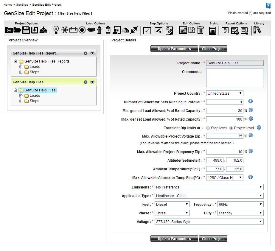
36 Table of Contents Page 36

37 c. Click on Update Parameters to save any changes to the project parameters. If you wish to change the project parameters for all new projects, change the new project default parameters by updating the parameters under My Profile. The project parameters set choices for site conditions, duty, fuel, operating voltage, project country, transient dip limits, maximum alternator temperature rise, minimum percent rated load, maximum percent rated load, frequency, generator set phase, generator sets running in parallel, emissions, and Application Type. When you click on the information icon, a quick tool tip will provide a quick explanation of some of the project parameter fields. Table of Contents Page 37
38 When you click Save Parameters, all the changes you made to the project will be reflected; you will be able to see them when you select the project in the Explorer tree. When you click Close, all the changes you made to the project will be discarded without being saved. Fuel Cummins recommends diesel fuel for emergency/standby power applications. Diesel fuel is readily available, comparatively less volatile than spark-ignited fuels (gasoline, liquid propane and natural gas), and readily stored on site. There are some precautions that must be followed: 1. Refer to and follow all local fire code regulations regarding storage requirements. 2. Diesel fuel has a limited storage life. Proper tank sizing should allow for fuel turnover based on scheduled exercise, test and running periods. 3. Local emission regulations may limit allowable emissions and may restrict annual operating hours. In these areas, gaseous fuel may be the preferable choice, particularly for prime power applications. 4. If diesel fuel is to be stored in cold climates, use the proper seasonal grade of fuel for each season. Fuel heating may also be required. 5. The fuel type will affect available voltage choices; not all voltage choices are available for each type of fuel. Selecting all fuels will allow you to compare performance of sets using different fuels. Emissions A list of emissions compliance requirements is provided in the GenSize project parameters. Select the emission compliance from the list provided to conform to the local emission regulations at the generator set installation site. Only those generators that meet the emissions requirement selected will be considered for sizing. Selecting Outside of U.S. and E.U. application from the drop-down menu will result in all generator sets available for the country selected in the project parameters. Frequency Most applications in North America operate at 60 Hz (1800 rpm). Many international locations operate at 50 Hz (1500 rpm). Generator set available operating voltage choices are frequency specific. Generator Set Phase This phase refers to the windings of an AC generator. In a three-phase generator, there are three or four output conductors, typically designated as A-B-C, R-S-T, or U-V-W and a neutral designated N. The phases are 120 electrical degrees apart. That is, the instance at which the three-phase voltages pass through zero or reach their maximums are 120 electrical degrees apart, where one complete cycle is considered 360 degrees. A single-phase generator has three output leads, typically two hots and a neutral. Three-phase generators can be connected for single-phase output but may be derated for single-phase operation. Table of Contents Page 38
39 Loads equipment is either three-phase or single-phase. A three-phase load cannot be placed on a single-phase generator set, but a three-phase generator set can accommodate single-phase loads. Unless specified, all loads are assumed to be single-phase and are assumed to be connected to a threephase generator with equal loading on all three phases. Note that unbalanced single-phase loads can cause generator voltage imbalance, which can negatively affect both the generator set and the load. Generator Sets Running in Parallel For applications with large load requirements, more than one generator set may be required. Each generator set will have exactly the same configuration. Although GenSize will allow it, we do not recommend running more than nine generator sets in parallel. You may need to consider another vendor with a larger load capacity. When load requirements are larger than can be met by a single generator set, or when enhanced system reliability is desired, generator sets may be paralleled. Adding paralleling controls allows a generator set to operate with other generators to serve a common load. The output of a set of paralleled generator sets is the sum of the individual capacities of the generator sets. Both total system power and individual generator set power requirements are contained in the recommended generator set reports. Transient Dip Limits Transient Dip Limits There are two options for defining transient voltage and frequency dip limits when sizing a project: 1. Transient Dip Limits at Step Level Using this method, GenSize determines the voltage and frequency dip limit for each step based on the voltage dip and frequency dips defined for each load in that step. Acceptable values transient limits for each load are entered in the Load Transient Limits section. From all the loads in the step, GenSize takes the most stringent requirement for voltage dip limit and frequency dip limit and sets those values as the limits for the step. For example, if the first step has a motor load with a voltage and frequency dip limit of 35% and 10%, respectively, and a UPS load with a voltage and frequency dip limit of 15% and 5%, the transient voltage and frequency dip limits for that step will be 15% and 5%. Note that dip limits of subsequent steps cannot exceed dip limits of a previous step. This is to ensure that the dip limits of the loads on the previous step are not exceeded when the loads on the subsequent step are started. The project is sized to ensure that none of the step level voltage and frequency dips are exceeded. 2. Project Level Dip Limits Using this method, the user enters a global limit for maximum allowable voltage and frequency dip for the project in the project parameters. These values are then pushed into the load transient limits for each load. That is, the project level dip limits will be reflected in the load transient limits in each load. The only exception is the fire pump load, where the default maximum voltage dip limit is always defaulted to 15%. Note again that dip limits of subsequent steps cannot exceed dip limits of a previous step. This is to ensure that the dip limits of the loads on the previous step are not exceeded when the loads on the subsequent step are started. If a load has no fire pump load, then all the steps will have the same voltage and frequency dip limit as entered in the project parameters. However, if a step has a fire Table of Contents Page 39

40 pump load, then the voltage dip limit for that step and all subsequent steps will be limited to the fire pump voltage dip or the project level voltage dip limit (whichever is smaller). The project is sized to ensure that none of the step level voltage and frequency dips are exceeded. The voltage and frequency dip limits for each step are displayed in the Step Level Dips Summary table in the Transient Performance Details section, which can be viewed after a project has been sized. The step level dip limits are also displayed in the Steps and Dips Detail Report. Maximum Allowable Step Voltage Dip Since a generator set is a limited power source, voltage and frequency excursions will occur during transient loading events. The key is to select a generator set size that will limit these excursions to an acceptable level for proper load performance. As the maximum allowable starting voltage dip is reduced, the size of the recommended generator set increases. If the maximum allowable starting voltage dip is less than 15%, the recommended generator set may be very large for the connected load. Some loads are more sensitive to voltage dip than others. It is recommended to choose the most sensitive load in your project to establish the maximum allowable voltage dip while the loads are starting. Note that for the majority of loads, maximum allowable voltage dip defaults at 35%. For North America, the maximum allowable peak voltage dip for fire pump loads defaults at a fixed 15%, and for medical imaging loads it defaults at a fixed 10%. See also Loads Overview. Maximum Allowable Step Frequency Dip Since a generator set is a limited power source, voltage and frequency excursions will occur during transient loading events. The key is to select a generator set size that will limit these excursions to an acceptable level for proper load performance. As the maximum allowable frequency dip is reduced, the size of the recommended generator set increases. If assigning an overall maximum allowable frequency dip for the project in the project parameters, choose the load most sensitive to frequency dips to set the maximum allowable frequency dip. Maximum Allowable Peak Voltage Dip Since a generator set is a limited power source, voltage and frequency excursions will occur during transient loading events. The key is to select a generator set size that will limit these excursions to an acceptable level for proper load performance. Peak Voltage Dip is calculated for certain surge loads. Table of Contents Page 40
41 Loads that require high peak power when operated (Medical Imaging Loads, Fire Pump Loads and Welding Loads) may require a limited voltage dip for proper performance. Peak voltage dip is also calculated for motor loads in the Cycle On and Off after they are initially started in a step. All of the surge loads are assumed to operate simultaneously with all non-surge loads running on the generator, creating a Cumulative Surge kw and kva and resulting in the calculated Peak Voltage Dip. The generator recommendation is made to limit this peak dip to less than the allowable dip. As the maximum allowable peak voltage dip is reduced, the size of the recommended generator set increases. GenSize automatically sets a peak voltage dip limit for medical imaging loads of 10% to get quality images and 15% for fire pumps when sizing a project in North America due to National Electric Code requirements. Maximum Allowable Peak Frequency Dip Since a generator set is a limited power source, voltage and frequency excursions will occur during transient loading events. The key is to select a generator set size that will limit these excursions to an acceptable level for proper load performance. Peak frequency dip is calculated for certain surge loads that require high peak power when operated (Medical Imaging Loads, Fire Pump Loads and Welding Loads). Peak frequency dip is also calculated for motor loads in the Cycle on and off after they are initially started in a step. All of the surge loads are assumed to operate simultaneously with all nonsurge loads running on the generator, creating a Cumulative Surge kw and resulting in the calculated Peak Frequency Dip. The generator recommendation is made to limit this peak dip to less than the allowable dip. As the maximum allowable peak frequency dip is reduced, the size of the recommended generator set increases. Peak Voltage Dip Limits Calculation In determining the peak voltage dip, GenSize looks at the smallest voltage dip limit in all steps in the project and 10% peak voltage dip requirement if a medical load is added to any of the steps. It then takes the smaller value of the two as the peak voltage dip limit. This limit is imposed when there are cyclic loads in the project so that the peak voltage dip calculated does not exceed the voltage dip limit of any of the loads connected to the generator. Peak Frequency Dip Limits Calculation In determining the peak frequency dip, GenSize looks at the smallest frequency dip limit in all steps in the project and sets this value as the peak frequency dip limit. This limit is imposed when there are cyclic loads in the project so that the peak frequency dip calculated does not exceed the frequency dip limit of any of the loads connected to the generator. Minimum Generator set Load Allowed, Percent of Rated Load Running a generator set lightly loaded can cause engine damage, and thus reliability problems. We do not recommend running diesel generator sets at less than 30% rated load, unless special precautions are taken, such as provisions for load bank testing as part of a regular maintenance program. Consult your local distributor for more information. With load bank exercising performed, a set running at less than 30% rated load can be recommended. However, running a set at less than 10% rated load can never be recommended. Maximum Generator set Load Allowed, Percent of Rated Load This represents the maximum level of loading allowed on a generator set at any given time. Generator set ratings are established to allow running at rated load, for a certain amount of time, but not continuously. The default value is set to 100%. When the total connected running load exceeds 90% of Table of Contents Page 41
42 rated power, it will be highlighted in yellow. Cummins recommends the user consider allowing additional generator set capacity for future load growth or for improved performance. If this has already been factored in by load choices and load demand, allowing 100% load may avoid light load operation or added conservatism. Site Conditions The site is the area or location in which the generator set will operate. Use the highest anticipated ambient temperature and altitude. The published performance is available only up to a specific altitude and temperature. Beyond those points (the altitude knee and temperature knee), the performance data must be derated by a certain percentage (the altitude slope and temperature slope). GenSize will automatically derate performance and display it. A decision will have to be made whether to locate the generator set inside the building or outside the building in a shelter or housing. The relative simplicity and cost effectiveness of an installation depends on the layout and physical location of all elements of the system: generator set, fuel tanks, louvers, ventilation, exhaust ducts, etc. We recommend indoor installation for generator sets supplying emergency loads where a minimum outdoor temperature of 40 F (4 C) cannot be reasonably assured. Code may require a minimum ambient temperature of 40 F (4 C) and that diesel generator sets be equipped with jacket water heaters to maintain the jacket water at a temperature sufficient to allow the generator set to start and accept the emergency load within 10 seconds. Ambient Temperature This refers to maximum expected or design ambient air temperature at the project site location where the generator is to be installed. All generator sets must be derated from the nominal rating at some temperature, shown as the temperature knee and at the stated rate, temperature slope in the sizing results/reports. Altitude This refers to altitude of the project site where the generator is to be installed. All generator sets must be derated from the nominal rating at some altitude, shown as the altitude knee and at the stated rate, altitude slope in the sizing results/reports. Maximum Allowable Alternator Temp Rise A maximum allowable alternator temperature rise over a 40 C ambient can be specified. This is the maximum temperature rise that will occur if the generator set is operated at the RkVA of the connected load. It may be desirable to use lower temperature rise alternators in applications that contain high nonlinear load content, where better motor starting is required, or in prime duty applications. Generally, setting a higher allowable temperature rise can result in a smaller recommended alternator and a smaller generator set. Temperature Rise at Full Rated Load The rated temperature rise is included for information purposes only. At less than full rated load, the actual alternator temperature rise will be lower. GenSize limits the actual alternator temperature rise with the connected load to the temperature rise selected in the Current Project Parameters. For example, to limit the actual alternator temperature rise to 80 C, select 80 C in Current Project Parameters. GenSize uses the alternator kw and kva at the 80 C rating as the available capacity to Table of Contents Page 42
43 compare with the sizing project's connected load, RkW and RkVA, respectively. If GenSize recommends an alternator rated at a higher rated temperature rise, it will be highlighted in yellow. This is important to understand if you plan on adding loads in the future. Loads added in the future will increase the actual temperature rise of the alternator. Voltage Operating voltage choices are limited by generator set models based on the Fuel, Frequency, and Phase selections. Select these values before choosing the generator set voltage. Load voltage may be selected independently of generator voltage and can be set to any value (example: 480 VAC system, 460 VAC motor nameplate voltage). The load running current will be calculated based on load voltage and other parameters. Generator Set Duty Ratings Duty GenSize performs all of its sizing based on situations where the generator set is isolated from a utility service. For these applications, you can size the generator set based on the standby or prime rating. When generator sets are paralleled with a utility service for an extended period of time, they should not be operated in excess of their continuous or base load rating. A standby system is an independent power system that allows operation of a facility in the event of normal power failure. The standby power rating is applicable for supplying emergency power for the duration of normal power interruption. No overload capability is available for this rating. The prime power rating is applicable for supplying electric power in lieu of commercially purchased power. Prime power is the maximum power available at variable load for an unlimited number of hours. A minimum of 10% overload capability is available for prime power ratings per BS 5514 and DIN Not every generator set configuration is available for prime duty. Selecting this choice will limit generator set recommendations to prime rated sets. The nominal generator set power rating may be derated according to the specified site conditions. The continuous rating is applicable for situations where a generator set is run at a constant power level in parallel with the utility service. The base load rating of a generator set is generally much lower than the prime power rating. Base load ratings for generator sets are not published, but are available from the factory. You may contact your local distributor for more information. Generator Connected Load This is the steady state power required by the loads assigned to starting steps in a project. This power is expressed as running kw and running kva. The generator rated load must meet or exceed the connected load requirements. Generator Nominal Power Rating Definitions Power ratings describe maximum allowable loading conditions on a generator set. The generator set will provide acceptable performance and life (time between overhauls) when applied according to the published ratings. It is also important to operate generator sets at a sufficient minimum load to achieve normal temperatures and properly burn fuel. Cummins recommends that a generator set be operated at a minimum of 30% of its nameplate rating. The following describes the ratings (Duty) used by Cummins. Note: For lean burn natural gas generator sets, GenSize output is based on tests using natural gas with Table of Contents Page 43
44 LHV of mj/nm3 (905 BTU/ft3) and coolant return temperatures within the stated data sheet limits. For operation on gas with lower heating values or with MI lower than stated Data Sheet limit or coolant return temperatures greater than Data Sheet limits, consult application engineering. Standby Power Rating - The standby power rating is applicable to emergency power applications where power is supplied for the duration of normal power interruption. No sustained overload capability is available for this rating (Equivalent to Fuel Stop Power in accordance with ISO3046, AS2789, DIN6271 and BS5514). This rating is applicable to installations served by a reliable normal utility source. This rating is only applicable to variable loads with an average load factor of 70%of the standby rating for a maximum of 200 hours of operation per year. In installations where operation will likely exceed 200 hours per year at variable load, the prime power rating should be applied. The standby rating is only applicable to emergency and standby applications where the generator set serves as the backup to the normal utility source. No sustained utility parallel operation is permitted with this rating. For applications requiring sustained utility parallel operation, the prime power or continuous rating must be utilized. Prime Power Rating - The prime power rating is applicable when supplying electric power in lieu of commercially purchased power. The number of allowable operating hours per year is unlimited for variable load applications but is limited for constant load applications as described below. (Equivalent to Prime Power in accordance with ISO8528). Unlimited Running Time Prime Power - Prime power is available for an unlimited number of annual operating hours in variable load applications. Applications requiring any utility parallel operation at constant load are subject to running time limitations. In variable load applications, the average load factor should not exceed 70%of the prime power rating. The total operating time at the prime power rating must not exceed 500 hours per year. Limited Running Time Prime Power - Prime power is available for a limited number of annual operating hours in constant load applications such as interruptible, load curtailment, peak shaving and other applications that normally involve utility parallel operation. Generator sets may operate in parallel with the utility source up to 500 hours per year at power levels not to exceed the prime power rating. It should be noted that engine life would be reduced by constant high load operation. Any application requiring more than 500 hours of operation per year at the prime power rating should use the continuous power rating. Continuous Power Rating (Base Power Rating) - The base load power rating is applicable for supplying power continuously to a load up to 100% of the base rating for unlimited hours. This rating is applicable for utility base load operation. In these applications, generator sets are operated in parallel with a utility source and run under constant loads for extended periods of time. Generator Rated Load This is the electrical power the generator set is rated to produce at standard atmosphere conditions (sea level and 25 C), typically expressed in kw and kva or power factor (usually 0.8) for the assigned Duty. The duty defines a type of service the generator is used for. The rating is a nominal rating and subject to derates at specified site temperature and altitude. Standby Rating Generator sets may have any or all of three different duty ratings: standby, prime or continuous. For these applications, you can size the generator set based on the standby, prime or continuous rating. When generator sets are paralleled with a utility service for an extended period of time, they should not be operated in excess of the limited time prime or continuous load rating. Table of Contents Page 44
45 The standby power rating is applicable for supplying emergency power for the duration of normal power interruption. No overload capability is available for this rating. These systems are assumed to operate limited hours, typically less than 200 hours per year. Prime Rating Generator sets may have any or all of three different duty ratings: standby, prime or continuous. For these applications, you can size the generator set based on the standby, prime or continuous rating. When generator sets are paralleled with a utility service for an extended period of time, they should not be operated in excess of the limited time prime or continuous load rating. The prime power rating is applicable for supplying electric power in lieu of commercially purchased power. The prime rating can be applied as either an unlimited prime rating (PRP) or limited prime rating (LRP). The unlimited prime power is the maximum power available at variable load for an unlimited number of hours; however, the average load measured over a 24-hour period should not exceed more than 70% of the generator set prime rating. The limited prime rating is the maximum power available for a non-varying load for up to 500 hours per year. The full 100% of the generator set prime rating can be applied to a limited prime power application. Not every generator set configuration is available for prime duty. Selecting this choice will limit generator set recommendations to prime rated sets. Continuous Rating Generator sets may have any or all of three different duty ratings: standby, prime or continuous. For these applications, you can size the generator set based on the standby, prime or continuous rating. When generator sets are paralleled with a utility service for an extended period of time, they should not be operated in excess of the limited time prime or continuous load rating. The continuous rating is applicable for situations where a generator set is run at a constant power level in parallel with the utility service for unlimited hours. The continuous load rating of a generator set is generally significantly lower than the prime power rating. This rating is intended for unlimited hours at constant load. Not every generator set configuration is available for continuous duty. Selecting this choice will limit generator set recommendations to continuous rated sets. Working with Loads Loads Overview The first step in sizing a generator set is to identify all of the different type and size loads the generator set will need to support. If you have more than one load of a given size and type, you only need to enter it once, unless you want each of the loads to carry a different description. The quantity of each load can be set when you enter the load in the step starting sequence. The starting and running characteristics of many of the common loads have been researched and defaults included for these load characteristics in GenSize. You can choose to use the defaults or, if you know the characteristics of your load are different, change the load characteristic. If you have a load type other than what is identified in GenSize, use a miscellaneous load to define the load starting and running requirements. Based on the load characteristics, GenSize calculates values for running kw (RkW), running kva (RkVA), starting kva (SkVA), starting kw (SkW), starting power factor (SPF), peak kva (PkVA), peak kw (PkW), and running amps (RAmps). When non-linear loads are present, it may be necessary to over-size the alternator and GenSize calculates a value for the non-linear kva (NLL KVA) for the load. Table of Contents Page 45
46 Note that when entering single-phase loads on a three-phase generator set, GenSize assumes that all three-phase loads will be balanced among the three phases. Therefore, the single-phase loads are converted to an equivalent three-phase load for sizing purposes. This results in the single-phase load current being distributed across the three phases so the single-phase load current is divided by When a single-phase load is entered for a three-phase set application, the actual single-phase current will be displayed in the load entry form, but when the load is entered into a step (the step load is the balanced load applied to the generator), the step load current is converted to the equivalent threephase current. Load Considerations The first step in sizing a generator set is to identify all of the different type and size loads the generator set will need to support. The starting and running characteristics of many of the common loads have been researched and typical numbers are included as defaults for these load characteristics in GenSize. You can choose to use the defaults, or, if you know the characteristics of your load are different, change the load characteristic. If you have a load type other than what is identified in GenSize, use a miscellaneous load to define the load starting and running requirements. Based on the load characteristics, GenSize calculates values for starting kva (SkVA), peak kva (PkVA); starting kw (SkW), peak kw (PkW), running kva (RkVA) and running kw (RkW). When non-linear loads are present, it may be necessary to oversize the alternator, and GenSize calculates a value for the non-linear kva (NLL KVA) for the load. GenSize uses these values, in step totals and project totals, for selecting the proper capacity generator set. Certain loads require special sizing considerations such as: Large motor loads (over 50 hp) Non-linear loads Regenerative Loads Loads that exhibit a Peak Surge Fire Pumps Load Phase Single-phase loads can run on a three-phase generator set, but a three-phase load cannot run on a single-phase generator set. Also, single-phase loads are assumed to be connected balanced across the three phases on three-phase sets. Load Starting Steps Recommendations Set the number of load starting steps. Some generator sets have only one load starting step: all of the loads are started at exactly the same time. For many applications, it is advantageous to start the loads with the larger starting requirements first; then, after those loads are running, to start the rest of the loads. The starting sequence of loads might also be determined by codes, in which the emergency lights must come on first, then the life support equipment, then the computer systems, and finally the rest of the loads. Starting step sequencing of generator sets is accomplished with transfer switches using delayed transfer or some other controller type device. Multiple transfer switches with delayed transfer or some other controller device will be required in applications with multiple load starting steps. Remember, even though there is a controlled initial loading sequence, there may be uncontrolled load stopping and starting of certain loads and you may wish to check surge loading under those conditions (peak voltage dip). Table of Contents Page 46
47 As the system designer, you must ascertain the situations that result in the highest load conditions on the generator set, so that GenSize can size the generator set properly. Contact your local distributor or the factory for more information on this subject. Loads Which Exhibit Peak Surges Loads such as medical imaging equipment (X-ray, CAT scan, and MRI) and welders don't cause a high inrush current when connected to a generator set, but can cause a high surge at the time they are operated. GenSize takes this into account by calculating a cumulative surge kw and kva with all other loads connected and running. In the case of medical imaging loads, GenSize also imposes a maximum 10% voltage dip due to the known sensitivity of this equipment while capturing images. Loads which cycle on and off (such as an air conditioner) will also cause a surge after all of the other loads are running. Taking cyclic loads into account could significantly increase the size of the recommended set, and could invalidate any painstaking work taken during the process of placing loads in a step starting sequence. Also, GenSize assumes that all cyclic loads cycle simultaneously the worstcase condition. If you know your loads cycle out of sequence, you may choose to set only the highest surge load (PkW or PkVA) as cyclic. Multiple medical imaging loads in a project are assumed to operate simultaneously. If controls are in place to prevent simultaneous operation, the user is advised to take that into account when entering loads. All welding loads in a project are assumed to surge simultaneously with any cyclic loads. Load Cycle ON and OFF If the checkbox "Cycles On/Off" has not been checked, the calculation for voltage dips assumes that once a load has started and applied to the generator set, it will not be restarted. All loads designated as cyclic are assumed to cycle ON simultaneously. Load Kilovolt-Amperes (kva) KVA is a term for rating electrical devices; load current in amperes multiplied by rated operating voltage (multiplied by 1.73 for three-phase loads). In the case of three-phase generator sets, kva is the kw output rating divided by the rated power factor. The starting kva (SkVA) is the load kva requirement when initially applying power. This can be significantly higher than the running requirement, such as motor loads. The running kva (RkVA) is the steady state kva load, which will be applied to the generator set. Load Kilowatts The starting kw is the load kw requirement when initially applying power. This can be significantly higher than the running requirement, motor loads, for example. The running kw (RkW) is the steady state kw load, which will be applied to the generator set. Efficiency Efficiency is the ratio of energy output to energy input, such as the ratio between the mechanical energy output at the shaft of a motor and the electrical energy input to the motor. Non-linear Loads Electronic loads such as static UPS, variable frequency drives (VFD or VSD) and battery chargers are nonlinear and induce harmonic currents in the power system. When powered by relatively high impedance source such as a generator set, these harmonic currents can cause objectionable voltage distortion in Table of Contents Page 47
48 the generator output voltage. Typically, generator sets serving non-linear loads will need an over-sized alternator to lower the source impedance, thus limiting voltage distortion to an acceptable level. These devices can also be sensitive to voltage dip and rapidly changing frequency. Peak Surges A properly sized generator set must supply power for the running load requirements and also meet the sudden momentary increase in power demand for transient load requirements. Typically, the transient load requirements will determine the required capacity and rating of the generator set, in other words, if the generator set has enough capacity to meet the transient load requirement it will have adequate capacity for the running load power requirements. GenSize evaluates two types of transient loading, step starting loads and surge loads, in selecting the optimum generator set. Step loads are blocks of load(s) connected to the generator set by a transfer switch(es) or some other means of controlling the step sequence. Surge loads are loads that when connected, will occasionally demand a sudden increase in power either by cycling on and off, or will demand a sudden increase in power due to its use, such as a welder or a medical imaging load. GenSize uses the greater power demand of either the transient step load or the transient surge load to size the generator set. Rectifier Pulse A static UPS or battery charger uses silicon controlled rectifiers (SCR) or other static switching device to convert AC voltage to DC for charging batteries, which are the storage medium. Specify the number of static switching devices contained in the rectifier section. A UPS or battery charger is a non-linear load requiring an oversized alternator. Larger alternators are required to prevent overheating due to the harmonic currents induced by the rectifiers and lower the alternator reactance to limit generator voltage distortion. Regenerative Loads The regenerative power capacity of a generator set is specific to the engine used, and is published on the generator set specification sheet. If the regenerative power of the load exceeds the capacity of the generator set, the generator set may over speed and shut down on over speed protection. The over speed limit of a generator set is usually 125% of rated speed, or at 1800 RPM rated, about 2250 RPM. Applications that are most susceptible to this type of problem are where the elevator/crane/hoist is the major load on the generator set. Generally, making sure there are other connected loads, which can absorb the regenerative power, can solve the regeneration problem. For example, in a building with an elevator, transfer the light load to the generator first before transferring the elevator. Occasionally, an auxiliary load bank and controls are needed to be sure that the generator set is not affected by regeneration from load equipment. Loads such as elevators, cranes and hoists often rely on the capability of the source to absorb power during certain sequences of operation, typically for braking purposes. This is not a problem when operating from utility power. A generator set is a limited power source and has limited capability to absorb power, especially if no other loads are connected. GenSize does not consider regeneration as element of the recommendation because there is no way to anticipate which loads are connected at the time of regeneration. Single-Phase Load Unbalance Single-phase loads should be distributed as evenly as possible between the three phases on a threephase generator set in order to fully utilize the rated set capacity and limit voltage unbalance. It does not take load unbalance before the three-phase kva capacity must be derated. For example, as little as 10% unbalanced single-phase load would require limiting the three-phase balanced load to no more Table of Contents Page 48
49 than 75% of rated on some generators. Refer to your local distributor for an application manual for more information. To prevent premature insulation failure in loads such as three-phase motors, voltage unbalance should be kept below about 2 percent. Step Loads Step loads are blocks of load(s) connected to the generator set by a transfer switch(es) or some other means of controlling the step sequence. Each load applied in a step has a starting kw (SkW) and kva (SkVA) and the sum of starting loads is the transient step load. GenSize determines which step has the greatest transient step load, the maximum step kw and maximum step kva. The maximum step kw and kva are added to the running load requirements of the previous step(s). That total is called the cumulative step kw and the cumulative step kva. If the cumulative step kw and kva can be met by a generator set at full voltage the cumulative step kw and kva are used to recommend a generator set. If the demand for power of the cumulative step kw and kva can be met by a generator set at a sustained reduced output voltage during the transient load, GenSize uses the effective step kw and the effective step kva to recommend a generator set. If the effective kw and kva are used, GenSize highlights that in yellow. Surge Loads Surge loads have sudden increases in power demand caused by the operation of medical imaging equipment, welders and other loads which cycle on and off (cyclical loads). If none of the loads in the project cycle on and off, and none of the loads are welders or medical imaging loads, then there is no surge load requirement for the generator set (PkW, PkVA, Cumulative Surge kw, and Cumulative Surge kva = none). The PkW and PkVA values quantify the individual loads, which exhibit peak surges. The PkW and PkVA values of all peak surge loads are totaled as if they all demanded power simultaneously. That sum is added to the sum of the running kw and kva of all other loads to calculate the generator set capacity required to meet the peak surge demand. The Cumulative Surge PkW and PkVA represent this worstcase calculation. GenSize compares these peak surge values (Cumulative Surge PkW, Cumulative Surge PkVA) to the maximum step starting values (Maximum Step kw, Maximum Step kva), and uses the higher kw and kva values (step load or surge load) for sizing. These values must be equal to or lower than the generator set surge capacity (Site Rated Maximum SkW, Maximum kva) for the set to be recommended. Create New Load There are 10 different loads (they are listed in the order shown on the toolbar): Light, Air Conditioning, Battery, Medical, Motor, Fire Pump, UPS, User Defined, Welding and General Receptacle. Use one of the two options to create a load. 1. When the application is loaded, click a button on the toolbar: 2. To create a load from a pop-up menu, you should have a project opened in the Explorer tree. Rightclick on Loads, select New Load from the pop-up menu and select the load you need. Table of Contents Page 49


50 When the load has been added, the Loads section of the Explorer view tree will expand and this load will be highlighted. In the right part of the Explorer view tree the main input of the load will be in bold face (for example, if you add Air Conditioning Load, Tons will be in boldface in the right side of the Explorer tree view). Edit Load There are three ways to start editing a Load. Note: You should first have the load selected in the Explorer tree. 1. Click Click to Edit button located under the Edit Options in the GenSize toolbar menu: 2. Right-click on the Load in the Explorer tree and select Edit Load from the pop-up menu: Table of Contents Page 50


51 3. Click on the step folder in the Explorer Tree in which the load is located. Click on the Click to Edit icon in the Step Details section to make changes to the load. Delete Load There are two ways to delete a load. 1. Select a load you want to delete from the Loads folder in the Project Tree and click Click to Delete button located in the GenSize toolbar under Edit Options. 2. Right-click on the load name in the Explorer tree and select Delete Load from the pop-up menu. Table of Contents Page 51
, select loads you want to delete by checking the appropriate checkboxes. Click the Delete button from the GenSize toolbar.")

52 There is only one way to delete multiple loads. Select the Loads folder in the Explorer tree view. In the description section of the screen (right side), select loads you want to delete by checking the appropriate checkboxes. Click the Delete button from the GenSize toolbar. Load Definitions Generator Connected Load This is the steady state power required by the loads assigned to starting steps in a project. This power is expressed as running kw and running kva. Of course, the generator rated load must meet or exceed the connected load requirements. Generator Rated Load This is the electrical power the generator set is rated to produce at standard atmospheric conditions (sea level and 25 C), typically expressed in kw and kva or power factor (usually 0.8) for the assigned Duty. The duty defines a type of service the generator is used for. The rating is a nominal rating and subject to derates at specified site temperature and altitude. Table of Contents Page 52
53 Harmonic Content (THDI%) This is a measure of the presence of harmonics in current waveform expressed as a percentage of the fundamental frequency amplitude at each harmonic frequency. The Harmonic Content (THDI %) takes the root mean square (RMS) value of the fundamental and the series of harmonics. GenSize uses harmonic analysis to limit the harmonic voltage distortion to levels that are within acceptable limits defined by the user. A harmonic current signature is selected for each non-linear load based on the type of rectifier selected. Once all the loads are entered and the project is sized, GenSize calculates the RMS value of the resulting harmonic voltage distortion expected at the alternator terminals. Leading Power Factor Load Three-phase generator sets are rated for continuous operation at 0.8 PF (lagging) and can operate for short periods of time at lower power factors, such as when starting motors. Reactive loads that cause leading power factor can provide excitation power to the alternator, and if high enough, can cause alternator voltage to rise uncontrollably, damaging the alternator or loads or tripping protective equipment. A reasonable guideline is that a generator set can carry up to 10 percent of its rated kvar capability in leading power factor loads without being damaged or losing control of output voltage. The most common sources of leading power factor are lightly loaded UPS systems with input filters and power factor correction devices for motors. Loading the generator set with lagging power factor loads prior to the leading power factor loads can improve stability. It is also advisable to switch power factor correction capacitors on and off with the load. It is generally impractical to oversize a generator set (thus reducing the percentage of non-linear load) to correct for this problem. Note: Filter equipment is often sized for operation at the expected maximum load on the UPS or motor load. At light loads, there may be excess filter capacitance, causing a leading power factor condition and hence kvar being exported to the generator set. There is a limit to how much reverse kvar a generator can safely tolerate before it shuts down due to overvoltage. Contact your distributor for guidance on this matter. Regenerative Loads The application of generator sets to loads having motor-generator (MG) drives such as elevators, cranes and hoists require the consideration of regenerative power. In these applications, the motor-generator, which pumps electrical power back to the source to be absorbed, slows the descent of the elevator car or hoist. The normal utility source easily absorbs the regenerated power because it is an essentially unlimited power source. The power produced by the load simply serves other loads, reducing the actual load on the utility (mains). A generator set, on the other hand, is an isolated power source that has a limited capability of absorbing regenerative power. Regenerative power absorption is a function of engine friction horsepower at governed speed, fan horsepower, generator friction, windage and core losses (the power required to maintain rated generator output voltage). The regenerative power rating of the set appears on the recommended generator set s specification sheet and is, typically, 10%of the generator set power rating. (The generator drives the engine, which absorbs energy through frictional losses.) Note: Drives operating in regenerative mode (such as elevators or hoists) may send reverse kw to the generator set. There is a limit to how much reverse power a generator can safely tolerate before it needs to be shut down. Contact your distributor for guidance on this matter. Table of Contents Page 53

54 Non-linear Loads Typically, these are electronic loads that draw current in a non-sinusoidal fashion. Non-linear loads like UPS and VFDs induce harmonic currents in the electrical system. Harmonic currents flowing in a generator may result in additional heating and output voltage distortion. Depending on the degree of harmonic waveform distortion, this may lead to either instability of the generator s excitation system or to the control systems of the loads applied to the generator. Voltage distortion is a function of the generator source internal impedance (sub-transient reactance). In order to limit distortion to levels acceptable to the connected load, the amount of current distortion produced by the load must either be limited or the source impedance must be reduced, resulting in oversized alternators being recommended. Most generators produced today can cope with high levels of waveform without detrimental effect to themselves; however, most problems occur with electronic power device control equipment trying to synchronize with a distorted waveform. GenSize uses harmonic analysis to limit the harmonic voltage distortion to levels that are within acceptable limits defined by the user. A harmonic current signature is selected for each non-linear load based on the type of rectifier selected. Once all the loads are entered and the project is sized, GenSize calculates the RMS value of the resulting harmonic voltage distortion expected at the alternator terminals. Note that GenSize calculates the expected voltage distortion in the generator set output and the calculation is based on the load types entered in the project and reactance of the alternator. GenSize will only recommend generators for which the calculated THDV% is lower than the limit entered by the user. Total Harmonic Voltage Distortion (THDV%, RMS) GenSize uses harmonic analysis to limit the harmonic voltage distortion to levels that are within acceptable limits defined by the user. A harmonic current signature is selected for each non-linear load based on the type of rectifier selected. Once all the loads are entered and the project is sized, GenSize calculates the RMS value of the resulting harmonic voltage distortion expected at the alternator terminals. Note that GenSize calculates the expected voltage distortion on the voltage output of the generator set and the calculation is based on the load types entered in the project and reactance of the alternator only. GenSize will only recommend generators for which the calculated THDV% is lower than the limit entered by the user. The calculated value of the expected voltage distortion is displayed in the Load Running/Surge Requirements section once the project is sized. Table of Contents Page 54

55 Project Voltage Distortion Limit The Project Voltage distortion limit defines the maximum acceptable harmonic voltage distortion (VTHD%, RMS) for the entire project. This limit must be entered whenever a non-linear load is entered. Note that this is a project-level parameter and not a load-specific parameter. Hence it is the user s responsibility to enter a project level limit that considers the most sensitive loads in the system in terms of voltage distortion tolerance. Most generators produced today can cope with high levels of waveform without detrimental effect to themselves; however, most problems occur with electronic power device control equipment trying to synchronize with a distorted waveform. If GenSize finds different voltage distortion limits defined for different non-linear loads in the project, it will only consider the smallest limit as the project limit. The voltage distortion dip limit considered for the project is displayed in the Project Requirements Tab. Note that GenSize calculates the expected voltage distortion in output voltage of the generator set and the calculation is based on the load types entered in the project and reactance of the alternator. GenSize will only recommend generators for which the calculated THDV% is lower than the limit entered by the user. Rectifier Types A rectifier is essentially the front-end power electronics stage which is seen by the generator. It uses silicon controlled rectifiers (SCR) or another static switching device to convert AC voltage to DC. Specify the number of static switching devices contained in the rectifier section. GenSize uses harmonic analysis to limit the harmonic voltage distortion to levels that are within acceptable limits defined by the user. A harmonic current signature is selected for each non-linear load based on the type of rectifier selected. Once all the loads are entered and the project is sized, GenSize calculates the RMS value of the resulting harmonic voltage distortion. Different options for rectifier types are provided depending on whether a three- or single-phase load is being entered. Three-phase options: Traditional rectifier equipment is defined by the number of pulses (6 pulses up to 24 pulses). Table of Contents Page 55
. Single-phase options: This option is for traditional single-phase equipment in the 4 pulse rectifier.")

56 IGBT refers to modern high-frequency systems employing IGBT technology. The watch-out is that IBGT s may only be part of inverter output stage. The front-end converter stage may be diodes or thyristors (silicon controlled rectifiers). Single-phase options: This option is for traditional single-phase equipment in the 4 pulse rectifier. IGBT refers to modern high-frequency systems employing IGBT technology. Surge Loads This refers to a sudden change in generator load caused by load equipment operation that causes a peak voltage and frequency dip. Voltage Unbalance Three-phase generators serving single- and three-phase loads will exhibit a voltage imbalance between the phases if the single-phase loads are not balanced. GenSize assumes the single-phase loads are balanced. Unbalanced voltage will cause additional heating in the generator and connected loads and should be avoided. Motor loads, for instance, may overheat with voltage unbalance greater than 5%. Load Starting and Running Requirements Running Amps (RAmps) This is the running amperes for a load or step. Running kva (RkVA) This is the running kilovolt-amperes load. Running kw (RkW) This is the running kilowatt load. Running Power Factor (RPF) This is the steady-state running power factor of the load. Table of Contents Page 56
57 SkVA This is the starting kilovolt-amperes of a load. SkW This is the starting kilowatts of a load. Starting Power Factor This is the power factor of the load at the time it is initially energized or started. Non-linear kva When non-linear loads are present, it may be necessary to oversize the alternator and GenSize calculates a value for the non-linear kva (NLL KVA) for the load and uses this value to calculate the voltage distortion. Peak kw (PkW) The sudden increase of power in kw demanded by a cyclical load as it starts or by other surge loads like welders and medical imaging equipment when they operate. Peak kva (PkVA) The sudden increase of power in kva demanded by a cyclical load as it starts or by other surge loads like welders and medical imaging equipment when they operate. Table of Contents Page 57

58 Types of Loads Lighting Load Entering Lighting Loads Form Overview To add a new light load, simply enter the information as it appears on the form. Load Name Enter a meaningful name to describe your load. Load names should be unique. Power Requirements Choose kw, kva or Amps selection from the drop-down menu. Running kw Enter the steady-state kilowatts of the Light Load. Running kva Enter the steady-state kva load, which will be applied to the generator set. Running Amperes Enter the steady-state operating amperes of the Light Load. Table of Contents Page 58
59 Phase Select a single or three-phase load. Voltage Enter the voltage. Light Type Select the type of Light Load you are working with. Fluorescent low-pressure mercury type discharge lamp where most of the light is emitted by an excited layer of fluorescent material. The same load characteristics are used for ballast or electronic types. Both are non-linear loads, but GenSize ignores the non-linearity for this load type since this is usually a small part of the total connected load. Incandescent Standard bulb type lamp assemblies, which use a filament to create light. Discharge Lamps that produce light by passing a current through a metal vapor; includes highpressure sodium, metal halide, and mercury vapor discharge lighting. Max. % Voltage Dip Enter a percentage value of the voltage dip that is acceptable to the load. Note that this field is only editable if the Step Level Dips option was selected in the Project Parameters. If the Project Level Dips was selected in the Project Parameters than the global limits entered in the project parameters will be defaulted in this field. Max. % Frequency Dip Enter a percentage value of the frequency dip that is acceptable to the load. Note that this field is only editable if the Step Level Dips option was selected in the Project Parameters. If the Project Level Dips was selected in the Project Parameters, then the global limits entered in the Project Parameters will be defaulted in this field. Rectifier Type Select a rectifier type from the options provided. Options will vary based on whether you are entering a three-phase or single-phase load. Harmonic Content (THDI%) Enter the percentage value of the expected root mean square (RMS) current total harmonic distortion (THDI%) of the non-linear load. A default value will be pre-populated based on the type of rectifier you select. Voltage Distortion Limit (THDV%) Enter the percentage value of the acceptable level of voltage total harmonic distortion (THDV%) for the project. The THDV% value should be the root means square (RMS) value. A default value will be pre-populated; however, the user should consider the VTHD% tolerance limit for the most sensitive load type that will be running on the generator set and enter that value as the project THDV% Limit. Comments Enter a comment for the load. This feature is especially helpful if you are making changes to loads. Show/Hide Additional Settings Click on either the arrow or the Show Additional Settings button to open the Additional Settings. Table of Contents Page 59

60 Show Additional Settings Starting Requirements: Power Factor Enter Starting Power Factor if needed. Running Requirements: Power Factor Enter Running Power Factor if needed. Load Requirements Load requirements will be calculated based on the inputs given. Additional information can be found in the Performance Definitions section of the Help document. Finish Information will be saved and added to the project. Cancel Cancels the form. Hide Additional Settings Click on the arrow to close the additional settings. Scroll Bar Use the scroll bar to navigate up and down the load wizard. Table of Contents Page 60

61 Air Conditioning Load Entering Air Conditioning Loads Form Overview This form allows adding a new air conditioning load and making adjustments to default load characteristics. Option 1.1 Three-Phase Load selected Load Name Enter a meaningful name here to describe your load. Load names should be unique. Power Requirements Select Tons or BTU from the drop-down menu. AC Tons Enter the air conditioning rating in tons. GenSize simply converts tons to running KW for sizing air conditioning loads based on the chiller efficiency parameters entered by the user. One ton of air-conditioning is equal to 12,000 BTU per hour. Table of Contents Page 61
62 BTU Enter the air conditioning rating in BTU per hour. GenSize simply converts BTU to running KW for sizing air conditioning loads based on the chiller efficiency parameters entered by the user. 12,000 BTU per hour is equivalent to one ton of air conditioning. Chiller Efficiency Select EER, COP or kw per Ton from the drop-down menu. Energy Efficiency Ratio (EER) A term typically used to define cooling efficiencies of unitary airconditioning and heat pump systems. Enter a value within allowable limits. Coefficient of Performance (COP) is the basic parameter used to report efficiency of refrigerant based systems. Enter a value within allowable limits. kw per Ton The term kw/ton is commonly used for larger commercial and industrial airconditioning, heat pump and refrigeration systems. Enter a value within allowable limits. See also Air Conditioning Load Efficiency. Phase Select a single- or three-phase load. Three-phase load is selected by default. Voltage Enter the voltage. This can be different from the generator set voltage entered in the current project parameters. It is important to enter the load voltage when requested as this has a direct impact on load calculations like the running amps. Motor Type Select Standard NEMA Design B, C, or D, High Efficiency NEMA Design B or IEC. Standard NEMA Design B, C, or D is selected by default. Otherwise, check Variable Drive to indicate either a variable frequency drive or variable speed drive. See Option 1.2 Variable Drive selected below. Max. % Voltage Dip Enter a percentage value of the voltage dip that is acceptable to the load. Note that this field is only editable if the Step Level Dips option was selected in the Project Parameters. If the Project Level Dips was selected in the Project Parameters than the global limits entered in the project parameters will be defaulted in this field. Max. % Frequency Dip Enter a percentage value of the frequency dip that is acceptable to the load. Note that this field is only editable if the Step Level Dips option was selected in the Project Parameters. If the Project Level Dips was selected in the Project Parameters, then the global limits entered in the Project Parameters will be defaulted in this field. Table of Contents Page 62
 Enter the percentage value of the expected root mean square (RMS) current total harmonic distortion (THDI%) of the non-linear load.")
63 Option 1.2 Variable Drive selected Rectifier Type Select a rectifier type from the options provided. Harmonic Content (THDI%) Enter the percentage value of the expected root mean square (RMS) current total harmonic distortion (THDI%) of the non-linear load. A default value will be pre-populated based on the type of rectifier you select. Voltage Distortion Limit (THDV%) Enter the percentage value of the acceptable level of voltage total harmonic distortion (THDV%) for the project. The THDV% value should be the root means square (RMS) value. A default value will be pre-populated; however, the user should consider the VTHD% tolerance limit for the most sensitive load type that will be running on the generator set and enter that value as the project THDV% Limit. Ramp Options The default selection is Slow. Select either None, Slow or Fast. Slow ramp This means that nonlinear loads (e.g. UPS, VFD) are ramped up onto the generator with sufficient time to have minimal impact on generator set voltage and frequency output while starting. GenSize assumes that the step load will not exceed 10% of the starting power requirements of this load. This is typical for most applications with non-linear loads where the load is ramped on the generator set. Fast ramp This means that non-linear loads (e.g. UPS, VFD) are ramped up onto the generator to minimize the impact on generator set voltage and frequency output while starting. GenSize assumes that the step load will not exceed 40% of the starting power requirements of this load. Table of Contents Page 63

64 None If the ramp time is too fast, meaning not having sufficient appreciable impact on reducing the starting power requirements of the load, then select the no ramp option. Comments Enter a comment for the load. This feature is especially helpful if you are making changes to loads. Show/Hide Additional Settings Click on either the arrow or the Show Additional Settings button to open the Additional Settings. Option 1.3 Across the line Method selected Method: The look of the next screen depends on the method selected from the drop-down list. See Options 1.3, 1.4 and 1.5. If unsure how your reduced-voltage starter and load will react, select Across the line as the starting method. See also Three-Phase Starting Methods in Motor Load section of the Help document. Starting Requirements: Power Factor Enter the starting power factor. This text field is unavailable if the Resistive method has been selected. Table of Contents Page 64
65 Low Inertia Check to indicate a low inertia load. If you are unsure if a load is low or high inertia, use high inertia (leave low inertia unselected). This checkbox is available only if Across the line method has been selected. See also Low/High Inertia Motor Load in Motor Load section of the Help document. NEMA Code Letter Select desired NEMA Code Letter from the list. This drop-down list is unavailable if Solid State method has been selected. Locked Rotor kva/hp Factor Enter Locked Rotor kva/hp. This drop-down list is unavailable if Solid State method has been selected. See also Locked Rotor kilo-volt-amperes Factor in Motor Load section of the Help document. Running Requirements: Power Factor Enter running power factor. Load Cycles On/Off Check to indicate if the load will periodically turn off, and then back on again outside of the step starting sequence. Be aware that checking this box can cause the required generator set to be much larger. If this checkbox is selected, peak load requirements are calculated. Load Requirements Load requirements will be calculated based on the inputs given. Load peak requirements are calculated if the Load Cycles On/Off checkbox is checked. Additional information can be found in the Performance Definitions section of the Help document. Finish Information will be saved and added to the project. Cancel Cancels the form. Hide Additional Settings Click on the arrow to close the additional settings. Scroll Bar Use the scroll bar to navigate up and down the load wizard. Table of Contents Page 65

66 Option 1.4 Autotransformer Method is selected Tap Select the tap from the drop-down list. This drop-down list is available only if Auto Transformer, Reactive or Resistive Methods have been selected. Table of Contents Page 66

67 Option 1.5 Solid State Method selected Current Limit (% FLA) Enter the current limit settings. Solid-state starters can adjust the starting torque, acceleration ramp time, and current limit for a controlled acceleration of the mechanical load while starting motors. Auto ByPass Check this box if the solid state starter is equipped with an automatic bypass. See also Solid State Starter equipped with Bypass in Motor Load section of the Help document. Rectifier Type Select a rectifier type from the options provided. Harmonic Content (THDI%) Enter the percentage value of the expected root mean square (RMS) current total harmonic distortion (THDI%) of the non-linear load. A default value will be pre-populated based on the type of rectifier you select. Voltage Distortion Limit (THDV%) Enter the percentage value of the acceptable level of voltage total harmonic distortion (THDV%) for the project. The THDV% value should be the root means square (RMS) value. A default value will be pre-populated; however, the user should consider the VTHD% tolerance limit for the most sensitive load type that will be running on the generator set and enter that value as the project THDV% Limit. Table of Contents Page 67
 and Option 2 (Single-phase Load) is the Motor Type drop-down list. Motor Type Select the desired motor type from the drop-down list.")
68 Option 2.1 Selecting Single-Phase load and shaft horsepower greater than 0 and less than 0.5 The main difference between Option 1 (Three-phase Load) and Option 2 (Single-phase Load) is the Motor Type drop-down list. Motor Type Select the desired motor type from the drop-down list. Otherwise, check Variable Drive to indicate either a variable frequency drive or variable speed drive. See also Single-Phase Motor Type in Motor Load section of the Help document. Table of Contents Page 68
 is the")
69 Option 2.2 Single-Phase Load and Motor Type selected The main difference of this form from Option 1 (Selecting Three-Phase Load) is the absence of the Starting Method drop-down list, which is only available for Three-Phase Loads. Table of Contents Page 69
 is the availability of only two motor types (instead of four motor types). However, you can still check Variable Drive to indicate a variable frequency drive or variable speed drive.")
70 Option 2.3 Single-Phase Load with Shaft Horsepower greater than 0.5 The main difference of this form from Option 2.1 (Selecting Single-phase Load with Shaft Horsepower greater than 0 and less than 0.5) is the availability of only two motor types (instead of four motor types). However, you can still check Variable Drive to indicate a variable frequency drive or variable speed drive. Air Conditioning Load Efficiency The air conditioning system efficiency depends on the energy consumed. Three options are provided to enter the efficiency of the air conditioning system: kw per Ton A term commonly used for larger commercial and industrial air-conditioning systems. It is the ratio of energy consumption in kw to the rate of heat removal in tons at the rated condition. The lower the kw/ton the more efficient the system. Coefficient of Performance (COP) COP is the basic parameter used to report efficiency of refrigerant-based systems. COP is used to define both cooling efficiencies and heating efficiencies as for heat pumps. A higher COP means a more efficient system. o Cooling - COP is defined as the ratio of heat removal to energy input to the compressor o Heating - COP is defined as the ratio of heat delivered to energy input to the compressor Table of Contents Page 70
71 Energy Efficient Ratio (EER) EER is a term generally used to define cooling efficiencies of unitary air-conditioning and heat-pump systems. A higher EER means a more efficient system. Note: Selective Energy Efficient Ratios (SEER) is often given for residential systems. Typical EER for residential central cooling units = SEER. Air Conditioning Load Calculations GenSize simply converts tons or BTU of air conditioning to equivalent running kw and motor horsepower for sizing. The conversion is based on the chiller efficiency parameters entered by the user. A default efficiency of 1kW per ton is used and this equivalent to an EER value of 12. Note: For resistive type heating loads, enter the load as a User Defined Load after factoring in system efficiency. Conversion Formulas: - kw per Ton = 12 /EER - KW per Ton = 12 /(COP x 3.412) - COP = EER / EER = 12 / kw per Ton - EER = COP x Table of Contents Page 71

72 Battery Charger Load Entering Battery Charger Load Form Overview This form allows adding a new battery charger load. A battery charger consists of a rectifier assembly used to charge batteries. A battery charger is a non-linear load requiring an oversized alternator. Load Name Enter a meaningful name here to describe your load. Load names should be unique. Rated Output Select Rated Output kva or Output Amps from the drop-down menu and enter the corresponding numeric value for that field. Nominal VDC Enter the nominal direct current (DC) voltage of the battery system. The default suggested value is 48V DC. It is important to enter this field accurately if Output Amps is entered in the Rated Output field since the power requirement is calculated based on the Output Amps and Nominal VDC value. Table of Contents Page 72
73 Phase Select a single- or three-phase load. Three-phase load is selected by default. Voltage Enter the voltage. This can be different from the generator set voltage entered in the current project parameters. It is important to enter the load voltage when requested as this has a direct impact on load calculations like the running amps. Rectifier Type Select a rectifier type from the options provided. Options will vary based on whether you are entering a three-phase or single-phase load. Harmonic Content (THDI%) Enter the percentage value of the expected root mean square (RMS) current total harmonic distortion (THDI%) of the non-linear load. A default value will be pre-populated based on the type of rectifier you select. Voltage Distortion Limit (THDV%) Enter the percentage value of the acceptable level of voltage total harmonic distortion (THDV%) for the project. The THDV% value should be the root means square (RMS) value. A default value will be pre-populated; however, the user should consider the VTHD% tolerance limit for the most sensitive load type that will be running on the generator set and enter that value as the project THDV% Limit. Max. % Voltage Dip Enter a percentage value of the voltage dip that is acceptable to the load. Note that this field is only editable if the Step Level Dips option was selected in the project parameters. If the Project Level Dips was selected in the Project Parameters, then the global limits entered in the Project Parameters will be defaulted in this field. A default value will be pre-populated based on typical acceptable limits for this type of load. Max. % Frequency Dip Enter a percentage value of the frequency dip that is acceptable to the load. Note that this field is only editable if the Step Level Dips option was selected in the project parameters. If the Project Level Dips was selected in the Project Parameters, then the global limits entered in the Project Parameters will be defaulted in this field. A default value will be pre-populated based on typical acceptable limits for this type of load. Comments Enter a comment for the load. This feature is especially helpful if you are making changes to loads. Show/Hide Additional Settings Click on either the arrow or the Show Additional Settings button to open the Additional Settings. Table of Contents Page 73

74 Show Additional Settings Starting Requirements: Power Factor Enter Starting Power Factor if needed. Running Requirements: Power Factor Enter Running Power Factor if needed. Efficiency Enter running efficiency of the load. Load Requirements Load requirements will be calculated based on the inputs given. Additional information can be found in the Performance Definitions section of the Help document. Finish Information will be saved and added to the project. Cancel Cancels the form. Hide Additional Settings Click on the arrow to close the additional settings. Scroll Bar Use the scroll bar to navigate up and down the load wizard. Table of Contents Page 74

75 Medical Imaging Load Entering Medical Imaging Load Form Overview This form allows adding a new medical imaging load, such as a CAT scan, MRI or X-ray machine. Note: This equipment is very sensitive to voltage dip while being run to capture and image. Load Name Enter a meaningful name here to describe your load. Load names should be unique. Power Requirements Choose Amps or kva selection from the drop-down menus. Running Amps Enter the steady-state operating amperes of the medical imaging equipment. Running kva Enter the steady-state kva load, which will be applied to the generator set. Peak Amperes Enter the peak amperes when the medical imaging equipment takes the image, usually expressed as milli-amperes. Peak kva Enter the peak kva when the medical imaging equipment takes the image. Table of Contents Page 75
76 Phase Select a single- or three-phase load. Voltage Enter the voltage. Rectifier Type - The default selection is None. If the load is a non-linear load, select a rectifier type from the options provided. Harmonic Content (THDI%) - Enter the percentage value of the expected root mean square (RMS) current total harmonic distortion (THDI%) of the non-linear load. Voltage Distortion Limit (THDV%) Enter the percentage value of the acceptable level of voltage total harmonic distortion (THDV%) for the project. The THDV% value should be the root means square (RMS) value. A default value will be pre-populated, however, the user should consider the VTHD% tolerance limit for the most sensitive load type that will be running on the generator set and enter that value as the project THDV% Limit. Max. % Voltage Dip Enter a percentage value of the voltage dip that is acceptable to the load. Note that this field is only editable if the Step Level Dips option was selected in the project parameters. If the Project Level Dips was selected in the project parameters, then the global limits entered in the project parameters will be defaulted in this field. Max. % Frequency Dip Enter a percentage value of the frequency dip that is acceptable to the load. Note that this field is only editable if the Step Level Dips option was selected in the project parameters. If the Project Level Dips was selected in the project parameters than the global limits entered in the project parameters will be defaulted in this field. Peak voltage dip will be limited at 10% once the medical imaging load is assigned to a step in the project. Comments Enter a comment for the load. This feature is especially helpful if you are making changes to loads. Show/Hide Additional Settings Click on either the arrow or the Show Additional Settings button to open the Additional Settings. Table of Contents Page 76

77 Show Additional Settings Starting Requirements: Power Factor Enter Starting Power Factor if needed. Peak Requirements: Power Factor Enter Peak Power Factor if needed. Running Requirements: Power Factor Enter Running Power Factor if needed. Load Requirements Load requirements will be calculated based on the inputs given. Additional information can be found in the Performance Definitions section of the Help document. Finish Information will be saved and added to the project. Cancel Cancels the form. Hide Additional Settings Click on the arrow to close the additional settings. Scroll Bar Use the scroll bar to navigate up and down the load wizard. Table of Contents Page 77
78 Medical Imaging Voltage Dip Calculations GenSize calculates a peak voltage dip when a medical imaging load is operated to obtain the image. This dip must be limited to 10% to protect the quality of the image. If the peak voltage dip is set higher in the project parameters, GenSize automatically sets the Maximum Allowable Peak Voltage Dip to 10% when medical loads are entered into steps. The generator set is then sized to limit the voltage dip to 10% when all medical imaging equipment entered into steps is operated (assumes worst case of all operating simultaneously) and all other non-surge type loads are running on the generator. If other surge loads like cyclic motor loads are present, the peak load will include those as well and still limit the Maximum Allowable Peak Voltage Dip. The user is prompted to reset Maximum Allowable Peak Voltage Dip if medical imaging loads are removed from all steps. Notice that we have assumed that the medical imaging equipment is not being operated while loads are starting, so the starting voltage dip is calculated separately and is allowed to exceed 10%. Peak Amperes Medical imaging loads operate at very high voltage from the secondary of the input transformer. In order to estimate generator set performance (particularly voltage dip), you must input the peak operating kilovolt-amperes or the peak ampere surge that will occur while operating medical imaging equipment. To ensure a good medical image, GenSize selects a generator set with sufficient capacity to limit the peak voltage dip to 10% or less. Peak kw (PkW) The sudden increase of power in kw demanded by a cyclical load as it starts or by other surge loads like welders and medical imaging equipment when they operate. Peak kva (PkVA) The sudden increase of power in kva demanded by a cyclical load as it starts or by other surge loads like welders and medical imaging equipment when they operate. Table of Contents Page 78

79 Motor Load Entering Motor Load Form Overview This form is used to add a new motor load and make adjustments to default motor load characteristics. Option 1.1 Three-Phase Load selected Load Name Enter a meaningful name here to describe your load. Load names should be unique. Power Requirements Select Hp, kw or Amps selection from the drop-down menu. Except where nameplate horsepower is entered directly, GenSize converts the entry units from kw, AC Tons, or full load amps into a nominal horsepower. The nominal horsepower is then used to select a set of motor characteristics from a database for a typical motor of that rating. Shaft Horsepower Enter the motor horsepower from the nameplate. Shaft KW Enter the nameplate kilowatt rating of the motor. GenSize will convert this kw to an equivalent motor horsepower to calculate the load running and starting requirements. Table of Contents Page 79
80 Running Amps Enter the full load amperes from the motor nameplate. GenSize converts the Running Amps input into a nominal hp for sizing purposes. Phase - Select a single- or three-phase load. Three-phase load is selected by default. Voltage Enter the voltage. This can be different from the generator set voltage entered in the current project parameters. It is important to enter the load voltage when requested as this has a direct impact on load calculations like the running amps. Max. % Voltage Dip Enter a percentage value of the voltage dip that is acceptable to the load. Note that this field is only editable if the Step Level Dips option was selected in the project parameters. If the Project Level Dips was selected in the project parameters than the global limits entered in the project parameters will be defaulted in this field. Max. % Frequency Dip Enter a percentage value of the frequency dip that is acceptable to the load. Note that this field is only editable if the Step Level Dips option was selected in the project parameters. If the Project Level Dips was selected in the project parameters than the global limits entered in the project parameters will be defaulted in this field. Motor Type Select Standard NEMA Design B, C, or D, High Efficiency NEMA Design B, or IEC. Standard NEMA Design B, C, or D is selected by default. Otherwise check Variable Drive to indicate either a variable frequency drive or variable speed drive. Table of Contents Page 80
 - Enter the percentage value of the expected root mean square (RMS) current total harmonic distortion (THDI%) of the non-linear load.")
81 Option 1.2 Variable Drive selected Rectifier Type Select a rectifier type from the options provided. Harmonic Content (THDI%) - Enter the percentage value of the expected root mean square (RMS) current total harmonic distortion (THDI%) of the non-linear load. Voltage Distortion Limit (THDV%) Enter the percentage value of the acceptable level of voltage total harmonic distortion (THDV%) for the project. The THDV% value should be the root means square (RMS) value. A default value will be pre-populated; however, the user should consider the VTHD% tolerance limit for the most sensitive load type that will be running on the generator set and enter that value as the project THDV% Limit. Ramp Options Select either None, Slow or Fast. The default selection is Slow. Slow Ramp This means that non-linear loads (e.g. UPS, VFD) are ramped up onto the generator with sufficient time to have minimal impact on generator set voltage and frequency output while starting. GenSize assumes that the step load will not exceed 10% of the starting power requirements of this load. This is typical most applications with non-linear loads where the load is ramped on the generator set. Fast ramp This means that nonlinear loads (e.g. UPS, VFD) are ramped up onto the generator to minimize the impact on generator set voltage and frequency output while starting. GenSize assumes that the step load will not exceed 40% of the starting power requirements of this load. Table of Contents Page 81

82 None If the ramp time is too fast, meaning not having sufficient appreciable impact on reducing the starting power requirements of the load, then select the no ramp option. Comments Enter a comment for the load. This feature is especially helpful if you are making changes to loads. Show/Hide Additional Settings Click on either the arrow or the Show Additional Settings button to open the Additional Settings. Option 1.3 Three-Phase Load and Across the line Method selected The look of the next screen depends on the Method selected from the drop-down list. If unsure how your reduced-voltage starter and load will react, select across the line starting method. See also Three-Phase Starting Method. Starting Requirements: Power Factor Enter the starting power factor. This text field is unavailable if Resistive method has been selected. Low Inertia Check to indicate a low inertia load. If you are unsure if a load is low or high inertia, use high inertia (leave low inertia unselected). This checkbox is available only if Across the Line method has been selected. See also Low/High Inertia Motor Load. Table of Contents Page 82
83 NEMA Code Letter select desired NEMA Code Letter from the list. This drop-down list is unavailable if Solid State method has been selected. Locked Rotor kva/hp enter Locked Rotor kva/hp. See also Locked Rotor kilo-volt-amperes Factor. This drop-down list is unavailable if Solid State method has been selected. Running Requirements: Power Factor Enter running power factor. Efficiency Enter running efficiency of the load. Load Cycles On/Off Check to indicate if the load will periodically turn off, and then back on again outside of the step starting sequence. Be aware that checking this box can cause the required generator set to be much larger. If this checkbox is selected, peak load requirements are calculated. Load Requirements Load requirements will be calculated based on the inputs given. Load peak requirements are calculated if the Load Cycles On/Off checkbox is checked. Additional information can be found in the Performance Definitions section of the Help document. Finish Information will be saved and added to the project. Cancel Cancels the form. Hide Additional Settings Click on the arrow to close the additional settings. Scroll Bar Use the scroll bar to navigate up and down the load wizard. Table of Contents Page 83

84 Option 1.4 Autotransformer Method selected Tap Select the tap from the drop-down list. This drop-down list is available only if Auto Transformer, Reactive or Resistive methods have been selected. Table of Contents Page 84

85 Option 1.5 Solid State Method selected Current Limit (% FLA) Enter the current limit settings. Solid-state starters can adjust the starting torque, acceleration ramp time, and current limit for a controlled acceleration of the mechanical load while starting motors. Auto Bypass Check this box if the solid state starter is equipped with an automatic bypass. See also Solid State Starter Equipped with Bypass. Rectifier Type Select a rectifier type from the options provided. Harmonic Content (THDI%) Enter the percentage value of the expected root mean square (RMS) current total harmonic distortion (THDI%) of the non-linear load. A default value will be pre-populated based on the type of rectifier you select. Voltage Distortion Limit (THDV%) Enter the percentage value of the acceptable level of voltage total harmonic distortion (THDV%) for the project. The THDV% value should be the root means square (RMS) value. A default value will be pre-populated; however, the user should consider the VTHD% tolerance limit for the most sensitive load type that will be running on the generator set and enter that value as the project THDV% Limit. Table of Contents Page 85
 and Option 2 (Single-phase Load) is the selections available in the Motor Type drop-down list.")
86 Option 2.1 Single-Phase Load with shaft horsepower greater than 0 and less than 0.5 The main difference between Option 1 (Three-phase Load) and Option 2 (Single-phase Load) is the selections available in the Motor Type drop-down list. Motor Type Select the desired motor type from the drop-down list. Otherwise, check Variable Drive to indicate either a variable frequency drive or variable speed drive. See also Single-Phase Motor Type. Table of Contents Page 86
 is the")
87 Option 2.2 Single-Phase Load and Motor Type selected The main difference of this form from Option 1 (Selecting Three-Phase Load) is the absence of the Starting Method drop-down list, which is only available for Three-Phase loads. Table of Contents Page 87
 is the availability of only two motor types (instead of four motor types). However, you can still check Variable Drive to indicate a variable frequency drive or variable speed drive.")
88 Option 2.3 Single-Phase Load with shaft horsepower greater than 0.5 The main difference of this form from Option 2.1 (Selecting Single-phase Load with Shaft Horsepower greater than 0 and less than 0.5) is the availability of only two motor types (instead of four motor types). However, you can still check Variable Drive to indicate a variable frequency drive or variable speed drive. Motor Load Calculations If the motor load is powered by a variable speed or variable frequency drive or is an AC drive on a DC motor, select the Variable Drive (Speed/Frequency) (VFD/VSD). A VFD or VSD is a non-linear load, requiring an oversized alternator to match the running load requirements. On the other hand, since drives ramp the load on, the starting requirements will be reduced compared to a motor started across the line. Select the appropriate front end rectifier type keeping in mind that higher pulse rectifier technology and/or filtering or IGBT type rectifiers will require less over sizing of the alternator to limit voltage distortion to acceptable values. Note that filter equipment is often sized for operation at the expected maximum load on the motor load. At light loads, there may be excess filter capacitance, causing a leading power factor condition and hence kvar being exported to the generator set. There is a limit to how much reverse kvar a generator can safely tolerate before it shuts down due to overvoltage. Contact your distributor for guidance on this matter. Table of Contents Page 88
89 Note that drives operating in regenerative mode (such as elevators or hoists) may send reverse kw to the generator set. There is a limit to how much reverse power a generator can safely tolerate before it needs to be shut down. Contact your distributor for guidance on this matter. Motor starting requirements can be reduced by applying some type of reduced voltage or solid state starter. Application of these devices can result in smaller generator set recommendations. However, caution must be used when applying any of these starting methods. First of all, motor torque is a function of the applied voltage and all of these methods result in lower voltage during starting. These starting methods should only be applied to low inertia motor loads unless it can be determined the motor will produce adequate accelerating torque during starting. Additionally, these starting methods can produce very high inrush currents when they transition from start to run if the transition occurs prior to the motor reaching very near operating speed, resulting in starting requirements approaching an across the line start. GenSize assumes the motor reaches near-rated speed before this transition, ignoring these potential inrush conditions. If the motor does not reach near-rated speed prior to transition, excessive voltage and frequency dips can occur when applying these starters to generator sets. If unsure how your starter and load will react, use across the line starting. For across the line motor starting, select low inertia load if you know the load requires low starting torque at low speeds. This will reduce the starting kw requirements for the generator set and can result in a smaller set. Low inertia loads are typically centrifugal fans and pumps. If unsure, use high inertia (leave low inertia unselected). Three-Phase Starting Methods Application of reduced voltage starters can result in smaller generator set recommendations. However, caution should be used when applying any of these starting methods because reduced voltage starting will result in reduced motor starting torque. Reduced voltage starting methods should only be applied with low inertia motor loads unless it can be determined the motor will produce adequate accelerating torque during starting. Additionally, reduced voltage starters will produce inrush currents similar to across the line starting when they transition from start to run if the transition occurs prior to the motor reaching very near operating speed. GenSize assumes the motor reaches near-rated speed before this transition, ignoring these potential inrush conditions. If the motor does not reach near-rated speed prior to transition, excessive voltage and frequency dips can occur when applying these starters to generator sets. If unsure how your starter and load will react, use across the line starting. There are several different methods available for starting three-phase motors. The most common is direct, across the line (full voltage) starting. If you want to reduce the starting peak kva requirements to either reduce the size of the generator set or to limit the voltage dip during motor starting, choose one of the reduced voltage starting methods. The three-phase motor starting methods supported by GenSize are: Across the line - Full voltage starting method. These controllers do not restrict the inrush current or starting torque of the motor since they connect the motor directly to the power source the instant the start signal is received. Table of Contents Page 89
90 Wye-Delta - Reduced voltage starting method using two contactors: a start contactor that connects the motor wye, and a run contactor that connects the motor delta. Autotransformer - Reduced voltage starting method using two contactors, a start and a run contactor, and an auto transformer connected in series with the motor windings during starting. Resistive - Reduced voltage starting method using two contactors, a start and a run contactor, and line resistors. Part winding - Reduced voltage starting method using two contactors and a six-lead dual voltage motor or a specially wound part-winding motor. The start contactor connects the motor starting windings. After a time delay, the run contactor closes and both motor windings are connected to the power source. When the transition occurs, the starting current jumps to the across the line starting current at the speed at which the transition took place. Solid state - Solid-state starters use SCRs to control the starting torque and current, the acceleration ramp time, and the inrush current limit to provide a soft start of the motor. Solid-state starters are a non-linear load and, unless a bypass contactor is included, will require additional alternator capacity to compensate for the load non-linearity. GenSize uses a factor of 2 x the required motor kw when a bypass contactor is not used. If a bypass contactor is used, the alternator does not need to be oversized. With a bypass contactor, GenSize ignores the non-linearity during the brief duration of motor acceleration. Reactive - Reduced voltage starting method using two contactors, a start and a run contactor, and line reactors. During starting, the reactors are connected in series with the motor windings and the power source. After a time delay, the main contactor is closed bypassing the reactors and applying full voltage to the motor windings. High Efficiency NEMA Design B High Efficiency NEMA Design B motors are premium efficiency squirrel-cage induction motors with minimum torque values, similar to design B C or D motors, but with higher maximum locked rotor kva and with higher nominal full-load efficiency. Large Motor Loads (over 50 HP) When starting a motor across-the-line with a generator set, the motor represents a low impedance load while at locked rotor or stalled condition, causing a high sustained inrush current; typically six times rated motor running current. The high current causes the generator voltage to drop. This voltage dip is comprised of two main components: the starting voltage dip and the recovery voltage dip. The initial starting voltage dip is strictly a function of the relative impedances of the generator and motor, and occurs instantaneously upon connecting the motor to the generator output. The starting voltage dip is the transient voltage dip predicted by the voltage dip curves published on the alternator data sheets. These dip curves give an idea of what might be expected for the initial transient dip assuming frequency is constant. If the engine slows down due to a heavy starting kilowatt requirement, the starting voltage dip may include an additional voltage dip as the torque-matching characteristic of the voltage regulator rolls off excitation to help the engine recover speed. Following the starting voltage dip, the generator excitation system detects the low voltage and responds by increasing excitation to recover to rated voltage. At the same time, the motor begins to accelerate to rated speed, assuming that the motor develops enough torque. For induction motors, motor torque is directly proportional to the square of the applied voltage. The rate at which the motor accelerates to rated speed is a function of the difference between the torque the motor develops and the torque requirements of the load. In order to avoid problems with excessive acceleration time or possibly stalling the motor, it important for the generator to recover to rated voltage as quickly as possible. GenSize selects an alternator sized to Table of Contents Page 90
91 provide the locked rotor kva of the motor load with no more than 10% recovery voltage dip during the motor acceleration. Recovery voltage dip of 10% maximum is a fixed parameter in GenSize, it is not user adjustable. The manner in which the generator voltage recovers is a function of several factors, including the relative sizes of the generator, the motor, the kilowatt capacity of the engine, and the generator excitation forcing capability. Several milliseconds after the initial starting voltage dip; the voltage regulator applies full forcing voltage to the generator exciter which results in main generator field current build up according to the exciter and main field time constants. All generator set components are designed and matched to achieve the shortest possible response time, yet maintain voltage stability without overloading the engine. Other fast-response excitation systems that respond too quickly and are too stiff can actually overload the engine when starting large motors. Depending on the severity of the load the motor accelerates to rated so that within several cycles to a few seconds the generator recovers to rated voltage. Various types of reduced voltage motor starters are available to reduce the starting kva of a motor in applications where reduced motor torque is acceptable. Reducing the starting kva will reduce the motor accelerating torque, which may not be acceptable for some mechanical loads or processes. Reducing motor starting kva can reduce the voltage dip, the size of the generator set, and provide a softer start mechanically. The use of closed-transition auto transformer starters for reduced voltage starting of large motor loads will reduce the size of the generator required relative to across-the-line starting. Resistor-type reducedvoltage motor starting may actually increase the size of the generator set required due to high starting power factors. Cyclic Motor Load Motor loads may cycle on and off automatically under some process control (liquid level, high temperature, etc.) after they are initially connected to the generator in a starting step. This is considered a surge load condition and GenSize allows calculations of peak voltage dip that occurs. Note that all cyclic motor loads are assumed to cycle simultaneously as a worst case. Use caution when selecting loads as cyclic, designing for a defined worst-case condition or oversized generators will result. Locked Rotor Kilovolt-Amperes Factor (LR-kVA / HP factor) The National Electrical Manufacturers Association (NEMA), in their standard for motors and generators (MGI), has specified accepted ranges of motor starting requirements under several different code letter designations. GenSize uses an average value of the NEMA locked rotor kva to calculate motor SkVA by multiplying the motor hp by the LRkVA factor. The locked rotor kva for premium efficiency Design E motors is higher than the equivalent HP Design B, C, & D motors. Low/High Inertia Motor Load The moment of inertia for a rotating mass is its resistance to acceleration. To start a motor and its load rotating, this inertia must be overcome by an accelerating torque, which translates directly to engine power. A load connected to the motor shaft has its moment of inertia and in practical situations, for specific equipment, this may or may not be available information. Fortunately, for the purpose of sizing the engine-generator set, or more specifically to determine the engine power needed to start and Table of Contents Page 91
92 accelerate a rotating motor load, the motor load moment of inertia need only be broadly categorized as low or high inertia. High-inertia loads are characterized by high breakaway torque requiring prolonged acceleration times and/or pulsating or unbalanced loads. For this purpose, low-inertia loads are those that can be accelerated with a service factor of 1.5 or less and high-inertia loads are those with a service factor greater than 1.5. Note: Pumps starting into high head pressure, large diameter fans or fans starting into high restriction should be classified as highinertia loads. For motors, the starting load is higher than the running load because the moment of inertia has to be overcome and the engine has to supply sufficient power for the motor to accelerate its load to rated speed. Examples of low-inertia loads include: Centrifugal Fans and Blower Fans Rotary Compressors Rotary Pumps and Centrifugal Pumps Examples of high-inertia loads include: Elevators Single and multi-cylinder pumps Single and multi-cylinder compressors Crushers Motor Starting Voltage Dip GenSize recommends generator sets that do not exceed the maximum allowable starting voltage dip specified in the project parameters. If the starting voltage dip is too high, more than 30-35%, motor starter holding coils may drop out. For motor starting applications, GenSize uses both the initial starting voltage dip and the recovery voltage during motor acceleration. It selects a generator that will not exceed the maximum allowable starting voltage dip specified in the current project parameters, and one that will recover to a minimum of 90 percent of rated output voltage with the full motor locked rotor kva applied to the generator. This translates to the motor delivering approximately 81% of its rated torque to the load during acceleration, which has proven adequate for most across-the-line starting applications. Nema Letter Code GenSize multiplies the motor horsepower by the corresponding multiplying factor in the following table to determine motor SkVA. NEMA Code Letter Range-kVA / HP GenSize multiplying factor A N B L C L Table of Contents Page 92
93 D L E L F L G L H K J K K K L K M K N K P K R K S J T J U J V 22.4 and up J GenSize uses the NEMA Code letter from the following Table as the default for calculating the motor locked rotor kva NEMA Code Letter hp Design B, C & D Design E 1 N N 1 L L 2 L L 3 K L 5 J L 7 H L 10 H L 15 G K 20 G K 25 G K 30 G K 40 G K 50 G K 60 G K 75 G K 100 G J 125 G J 150 G J 200 G J Table of Contents Page 93
94 250 G J 300 G J 350 G J 400 G J 500 & UP G J Variable Speed Drives Variable speed drives (VSDs or VFDs), which contain converters and inverters and are used to control the speed of induction motors, will induce the most severe voltage distortion on the generator output when compared to all other classes of non-linear load. For example, as a rule of thumb the VFD load on the generator must be less than approximately 50% of the generator capacity to limit the total harmonic distortion to less than 15% if the VFD utilizes a 6 pulse Silicon controller rectifier. Non-linear loads, such as variable speed drives, generate harmonics in their current waveform, which lead to harmonic distortion of the supply voltage waveform. Depending on the degree of harmonic waveform, this may lead to either instability of the generator s excitation system or to the control systems of the loads applied to the generator. Most generators produced today can cope with high levels of waveform without detrimental effect; however, most problems occur with electronic power device control equipment trying to synchronize with a distorted waveform. The level of operating system harmonic voltage distortion must be controlled to be within acceptable limits to all loads connected to the system. Generator sizing is critical to mitigate the risk of damage to the customer s connected equipment. Experience places a voltage distortion limit of 15% to variable speed drives. This can either be achieved by restricting the amount of current distortion produced by the load (selecting "cleaner" rectifiers with a higher number of pulses) or by simply increasing the size of the alternator. See also Non-linear Loads. For variable speed drive applications, size the generator set for the full nameplate rating of the drive, not the nameplate rating of the driven motor. Harmonics may be higher with the drive operating at partial load and it may be possible that a larger motor (up to the full capacity of the drive) could be installed in the future. Soft Ramp Options Three soft ramping options are provided for both the UPS load and Motor Load with Variable Speed Drive. Selecting a slow ramp option will reduce the Starting kw (skw) and starting kva (SkVA) requirements of the load. This in turn will mean smaller voltage dips and frequency dips. Slow ramp This means that nonlinear loads (e.g. UPS, VFD) are ramped up onto the generator with sufficient time to have minimal impact on generator set voltage and frequency output while starting. GenSize assumes that the step load will not exceed 10% of the starting power requirements of this load. This is typical for most applications with non-linear loads where the load is ramped on the generator set. Fast ramp This means that non-linear loads (e.g. UPS, VFD) are ramped up onto the generator to minimize the impact on generator set voltage and frequency output while starting. GenSize assumes that the step load will not exceed 40% of the starting power requirements of this load. Table of Contents Page 94
95 None If the ramp time is too fast, meaning not having sufficient appreciable impact on reducing the starting power requirements of the load, then select the no ramp option. Reduced Voltage Starting Methods Table 2. Reduced Voltage Starting Methods *These are percents or factors of running current, which depend on the value of the series resistances added to the rotor windings. Single-Phase Motor Type The Single-Phase Motor Types are: Capacitor start, induction run Capacitor start, capacitor run Split phase (available if horsepower is <= 0.5) Permanent split capacitor (available if horsepower is <= 0.5) Solid State Starter Equipped With Bypass If a bypass is not included with the starter, GenSize treats the motor as a non-linear load and an oversized alternator will be recommended to meet the project THDV% requirements. When the starter is equipped with a bypass, a bypass contactor bypasses the solid-state elements when the motor reaches full speed so the starter can be treated as a linear load. Standard NEMA Design B, C, or D Design B, C, or D motors are squirrel-cage induction motors classified by NEMA with minimum acceptable values for locked rotor torque, pull-up torque, and breakdown torque, and a maximum locked rotor kva for various code letters. IEC Motor The IEC Motor Load is a European standard motor type. The difference between IEC motors and a Standard NEMA Design B, C, or D is that IEC motors typically have higher starting requirements. Hence the default Locked Rotor kva/hp (or NEMA Letter Code) suggested by GenSize for a given motor size will be higher for IEC motors than for a Standard NEMA Design B, C, or D motor. Table of Contents Page 95

96 Fire Pump Load Entering Fire Pump Load Form Overview This form allows adding a new fire pump load and make adjustments to default fire pump load characteristics to match the pump s requirements. Option 1.1 Three-Phase Load selected. Load Name Enter a meaningful name here to describe your load. Load names should be unique. Power Requirements Select hp, kw or Amps selection from the drop-down menu. Except where nameplate horsepower is entered directly, GenSize converts the entry units from kw or full load amps into a nominal horsepower. The nominal horsepower is then used to select a set of motor characteristics from a database for a typical motor of that rating. Shaft Horsepower Enter the motor horsepower from the nameplate. Table of Contents Page 96
97 Shaft kw Enter the nameplate kilowatt rating of the motor. GenSize will convert this kw to an equivalent motor horsepower to calculate the load running and starting requirements. Running Amps Enter the full load amperes from the motor nameplate. GenSize converts the Running Amps input into a nominal hp for sizing purposes. Phase Select a single or three-phase load. Three-phase load is selected by default. Voltage Enter the voltage. This can be different from the generator set voltage entered in the current project parameters. It is important to enter the load voltage when requested as this has a direct impact on load calculations like the running amps. Note that peak voltage dip for this load should be at 15%. Max. % Voltage Dip U.S.A: If you are sizing a generator for an application in the U.S.A, this field will not be editable and will be defaulted to 15% (fire codes in the U.S.A. mandate a maximum of 15% voltage dip). Note that if Project Level Dips was selected in the project parameters and a global voltage dip limit of less than 15% was entered in the project parameters, this value will be reflected in this field. All other regions: For all other regions this field is editable. Enter a percentage value of the voltage dip that is acceptable to a fire pump load and also meets local code requirements if they exist. Note that if Project Level Dips was selected in the project parameters and a global voltage dip limit of less than 15% was entered in the project parameters, this value will be reflected in this field. Max. % Frequency Dip Enter a percentage value of the frequency dip that is acceptable to the load. Note that this field is only editable if the Step Level Dips option was selected in the project parameters. If Project Level Dips was selected in the project parameters, then the global limits entered in the project parameters will be defaulted in this field. Motor Type Select Standard NEMA Design B, C, or D, High Efficiency NEMA Design B or IEC. Standard NEMA Design B, C, or D is selected by default. Otherwise, check Variable Drive to indicate either a variable frequency drive or variable speed drive. See Option 1.2 below. Load Factor This field represents the level of load on the Fire Pump as a percentage of the Fire Pump s full nameplate rating. The default value is 100%. We recommend that the generator be sized to meet the full nameplate rating of the Fire Pump. Table of Contents Page 97
 Enter the percentage value of the expected root mean square (RMS) current total harmonic distortion (THDI%) of the non-linear load.")
98 Option 1.2 Variable Drive selected Rectifier Type Select a rectifier type from the options provided. Harmonic Content (THDI%) Enter the percentage value of the expected root mean square (RMS) current total harmonic distortion (THDI%) of the non-linear load. Voltage Distortion Limit (THDV%) Enter the percentage value of the acceptable level of voltage total harmonic distortion (THDV%) for the project. The THDV% value should be the root means square (RMS) value. A default value will be pre-populated, however, the user should consider the VTHD% tolerance limit for the most sensitive load type that will be running on the generator set and enter that value as the project THDV% Limit. Ramp Options The default selection is slow, select either None, Slow or Fast. Slow ramp This means that non-linear loads (e.g. UPS, VFD) are ramped up onto the generator with sufficient time to have minimal impact on generator set voltage and frequency output while starting. GenSize assumes that the step load will not exceed 10% of the starting power requirements of this load. This is typical of most applications with non-linear loads where the load is ramped on the generator set. Fast ramp This means that non-linear loads (e.g. UPS, VFD) are ramped up onto the generator to minimize the impact on generator set voltage and frequency output while starting. GenSize assumes that the step load will not exceed 40% of the starting power requirements of this load. Table of Contents Page 98

99 None If the ramp time is too fast, meaning not having sufficient appreciable impact on reducing the starting power requirements of the load, then select the no ramp option. Comments Enter a comment for the load. This feature is especially helpful if you are making changes to loads. Show/Hide Additional Settings Click on either the arrow or the Show Additional Settings button to open the Additional Settings. Option 1.3 Across the line Method selected Starting Requirements: Method: The look of the next screen depends on the method selected from the drop-down list. See Options 1.3, 1.4 and 1.5. If unsure how your reduced-voltage starter and load will react, select Across the line as the starting method. See also 3 Phase Starting Method in Motor Load section of the Help document. Power Factor Enter the starting power factor. This text field is unavailable if Resistive Method has been selected. Low Inertia Check to indicate a low inertia load. If you re unsure if a load is low or high inertia, use high inertia (leave low inertia unselected). This checkbox is available only if Across the Line Method has been selected. Table of Contents Page 99
100 See also Low/High Inertia Motor Load in Motor Load section of the Help document. NEMA Code Letter Select desired NEMA Code Letter from the list. This dropdown list is unavailable if Solid State Method has been selected. See also NEMA Code Letter in Motor Load section of the Help document. Locked Rotor kva/hp enter Locked Rotor kva/hp. This dropdown list is unavailable if Solid State Method has been selected. See also Locked Rotor kilo-volt-amperes Factor in Motor Load section of the Help document. Running Requirements: Power Factor Enter running power factor. Efficiency Enter the running efficiency of the load. Load Requirements Load requirements will be calculated based on the inputs given. Additional information can be found in the Performance Definitions section of the Help document. Finish Information will be saved and added to the project. Cancel Cancels the form. Hide Additional Settings Click on the arrow to close the additional settings. Scroll Bar Use the scroll bar to navigate up and down the load wizard. Table of Contents Page 100

101 Option 1.4 Autotransformer Method selected Tap Select the tap from the drop-down list. This drop-down list is available only if Auto Transformer, Reactive or Resistive Methods have been selected. Table of Contents Page 101

102 Option 1.5 Solid State method is selected Current Limit (% FLA) Enter the current limit settings. Solid-state starters can adjust the starting torque, acceleration ramp time, and current limit for a controlled acceleration of the mechanical load while starting motors. Auto ByPass Check this box if the solid state starter is equipped with an automatic bypass. See also Solid State Starter equipped with Bypass in Motor Load section of the Help document. Rectifier Type Select a rectifier type from the options provided. Harmonic Content (THDI%) Enter the percentage value of the expected root mean square (RMS) current total harmonic distortion (THDI%) of the non-linear load. Voltage Distortion Limit (THDV%) Enter the percentage value of the acceptable level of voltage total harmonic distortion (THDV%) for the project. The THDV% value should be the root means square (RMS) value. A default value will be pre-populated, however, the user should consider the VTHD% tolerance limit for the most sensitive load type that will be running on the generator set and enter that value as the project THDV% Limit. Table of Contents Page 102
 and Option 2 (Single-Phase Load) is the selections available in the Motor Type drop-down list.")
103 Option 2.1 Single-Phase Load with shaft horsepower greater than 0 and less than 0.5 The main difference between Option 1 (Three-Phase Load) and Option 2 (Single-Phase Load) is the selections available in the Motor Type drop-down list. Motor Type Select the desired motor type from the drop-down list. Otherwise, check Variable Drive to indicate either a variable frequency drive or variable speed drive. See also Single-Phase Motor Type in Motor Load section of the Help document. Table of Contents Page 103
")
104 Option 2.2 Selecting Single-Phase load and a Motor Type from the drop-down box The main difference of this form from Option 1 (Three-Phase Load) is the absence of the Starting Method drop-down list, which is only available for Three-Phase Loads. Table of Contents Page 104
 is the availability of only two motor types (instead of four motor types). However, you can still check Variable Drive to indicate a variable frequency drive or variable speed drive.")
105 Option 2.3 Single-phase Load with shaft horsepower greater than 0.5 The main difference of this form from Option 2.1 (Selecting Single-phase Load with Shaft Horsepower greater than 0 and less than 0.5) is the availability of only two motor types (instead of four motor types). However, you can still check Variable Drive to indicate a variable frequency drive or variable speed drive. Fire Pump Load Calculations GenSize will size the generator to limit the step voltage dip of any step containing a fire pump to 15%. The voltage dip in any subsequent step will also be limited to 15%. In addition, the peak voltage dip with all other non-surge loads running when starting the fire pump is also limited to 15%. Whenever a reduced voltage starter is used for a fire pump motor, the user should consider sizing for across-the-line starting, because the fire pump controller includes either a manual-mechanical, manualelectrical or automatic means to start the pump across-the-line in the case of a controller malfunction. GenSize will not disallow use of reduced voltage starters for fire pumps, however. Fire Pump Code Requirements The North American National Electrical Code (NEC) contains requirements limiting starting voltage dip to 15 percent when starting fire pumps. Other regions may have their own unique requirements. This limit is imposed in order to make certain that motor starters do not drop out during extended locked rotor Table of Contents Page 105
106 conditions and to make sure that the fire pump motor delivers adequate torque to accelerate the pump to rated speed to obtain rated pump pressure and flow. Table of Contents Page 106

107 UPS Load Entering UPS Load Form Overview This form allows adding a new UPS load. Load Name Enter a meaningful name here to describe your load. Load names should be unique. Rated kva Select either the Rated kva output or Rated kva input option from the dropdown menu. Note that if the Input kva value is entered it is assumed that the battery charging requirements and system efficiency have already been factored in. Phase Select a single or three-phase load. Three-phase load is selected by default. Voltage Enter the voltage. This can be different from the generator set voltage entered in the current project parameters. It is important to enter the load voltage when requested as this has a direct impact on load calculations like the running amps. Table of Contents Page 107
108 Rectifier Type Select a rectifier type from the options provided. Options will vary based on whether you enter a three-phase or single-phase load. Harmonic Content (THDI%) Enter the percentage value of the expected root mean square (RMS) current total harmonic distortion (THDI%) of the non-linear load. A default value will be pre-populated based on the type of rectifier you select. Voltage Distortion Limit (THDV%) Enter the percentage value of the acceptable level of voltage total harmonic distortion (THDV%) for the project. The THDV% value should be the root means square (RMS) value. A default value will be pre-populated, however, the user should consider the VTHD% tolerance limit for the most sensitive load type that will be running on the generator set and enter that value as the project THDV% Limit. Max. % Voltage Dip Enter a percentage value of the voltage dip that is acceptable to the load. Note that this field is only editable if the Step Level Dips option was selected in the project parameters. If Project Level Dips was selected in the project parameters, then the global limits entered in the project parameters will be defaulted in this field. A default value will be pre-populated based on typical acceptable limits for this type of load. Max. % Frequency Dip Enter a percentage value of the frequency dip that is acceptable to the load. Note that this field is only editable if the Step Level Dips option was selected in the project parameters. If Project Level Dips was selected in the project parameters, then the global limits entered in the project parameters will be defaulted in this field. A default value will be pre-populated based on typical acceptable limits for this type of load. Loading Factor This field represents the level of loading on the UPS as a percentage of the UPS s full nameplate rating. The default value is 100%. We recommend that the generator be sized to meet the full nameplate rating of the UPS. Ramp Options Three soft ramping options are provided for both the UPS load and Motor Load with Variable Speed Drive. Selecting a slow ramp option will reduce the Starting kw (skw) and starting kva (SkVA) requirements of the load. This in turn will mean smaller voltage dips and frequency dips. Slow ramp This means that non-linear loads (e.g. UPS, VFD) are ramped up onto the generator with sufficient time to have minimal impact on generator set voltage and frequency output while starting. GenSize that the step load will not exceed 10% of the starting power requirements of this load. This is typical for most applications with non-linear loads where the load is ramped on the generator set. Fast ramp This means that non-linear loads (e.g. UPS, VFD) are ramped up onto the generator to minimize the impact on generator set voltage and frequency output while starting. GenSize assumes that the step load will not exceed 40% of the starting power requirements of this load. None If the ramp time is too fast, meaning not having sufficient appreciable impact on reducing the starting power requirements of the load, then select the no ramp option. Comments - Enter a comment for the load. This feature is especially helpful if you are making changes to loads. Show/Hide Additional Settings Click on either the arrow or the Show Additional Settings button to open the Additional Settings. Table of Contents Page 108

109 Show Additional Settings Starting Requirements: Power Factor Enter starting power factor. Running Requirements: Power Factor Enter running power factor. Efficiency Enter running efficiency of the load. Battery Charge Rate Enter the battery charge rate as percentage of the UPS Output kva Rating. The battery charging power requirements will be added to the total power kw requirements for the UPS load. Note that the additional running power requirements will only be considered when the Output is selected in the Power Requirements section of the load. If the Input kva value is entered, it is assumed that the battery charging requirements and system efficiency have already been factored in. Load Requirements Load requirements will be calculated based on the inputs given. Additional information can be found in the Performance Definitions section of the Help document. Finish Information will be saved and added to the project. Cancel Cancels the form. Table of Contents Page 109
110 Hide Additional Settings Click on the arrow to close the additional settings. Scroll Bar Use the scroll bar to navigate up and down the load wizard. UPS Load Calculations A static UPS uses silicon controlled rectifiers (SCR) or another static device to convert AC voltage to DC for charging batteries and an inverter to convert DC to conditioned AC power to supply the load. A UPS is a non-linear load and may require an oversized alternator. Some incompatibility problems between generator sets and static UPSs have led to many misconceptions about sizing the generator set for this type of load. Past problems did occur and the recommendation from UPS suppliers at that time was to oversize the generator set from two to five times the UPS rating. Even then some problems persisted, and since then, those incompatibility problems have been addressed by most UPS manufacturers. It is more cost effective to require generator compatibility of the UPS supplier than to oversize the generator. If the batteries are discharged when the UPS is operating on the generator set, the generator set must be capable of supplying the rectifier for battery charging and the inverter to supply the load. A second reason to use the full UPS rating is that additional UPS load may be added in the future up to the nameplate rating. The non-linear load sizing in GenSize is based on the level of harmonics the UPS induces in the generator output depending on the level of UPS loading. Select the appropriate front end rectifier type keeping in mind that higher pulse rectifier technology and/or filtering or IGBT type rectifiers will require less oversizing of the alternator to limit voltage distortion to acceptable values. The typical acceptable level of harmonic voltage distortion for UPS and Admin building loads is generally 10%. The generator will be sized to limit the continuous voltage total harmonic distortion (THDV%, RMS) at the generator terminals in order to be within the limit entered in the Project VTHD% limit field. Note: Filter equipment is often sized for operation at the expected maximum load on the UPS or motor load. At light loads, there may be excess filter capacitance, causing a leading power factor condition and hence kvar being exported to the generator set. There is a limit to how much reverse kvar a generator can safely tolerate before it shuts down due to over-voltage. Contact your distributor for guidance on this matter. For multiple redundant UPS systems, size the generator set for the combined nameplate ratings of the individual UPSs. Redundant system applications are those where one UPS is installed to back up another and the two are online at all times with 50% or less load. UPS equipment often has varying power quality requirements depending on the operating mode. When the rectifier is ramping up, often relatively broad frequency and voltage swings can occur without disrupting equipment operation. However, when the bypass is enabled, both frequency and voltage must be very constant, or an alarm condition will occur. This occurs when rapidly changing UPS input frequency results from a sudden transient load change on a generator set. During this transient event, static UPSs with solid-state bypass switches must break synch with the source and disable the bypass. Note that in some cases it may be acceptable to allow the UPS to revert to the battery during transients that may occur when large cyclic air conditioning or motor loads cycle on and off. This can aid in getting a smaller sized generator set. In some cases, GenSize may recommend a generator if the peak voltage dip and/or the peak frequency dip have exceeded the transient frequency dip limit of one or more of the Table of Contents Page 110
111 UPS loads connected to the generator set. This might cause the UPS to momentarily revert to the battery. In this case, the peak voltage dip and/or the peak frequency dip displayed in the recommendation grid for a given generator set will be displayed as yellow. UPS Reverts to Battery during Transients Note that in some cases it may be acceptable to allow the UPS to revert to the battery during transients that may occur when large cyclic air conditioning or motor loads cycle on and off. This can aid in getting a smaller sized generator set. In some cases, GenSize may recommend a generator if the peak voltage dip and/or the peak frequency dip have exceeded the transient frequency dip limit of one or more of the UPS loads connected to the generator set. This might cause the UPS to momentarily revert to the battery. In this case, the peak voltage dip and/or the peak frequency dip displayed in the recommendation grid for a given generator set will be displayed as yellow. Table of Contents Page 111

112 User Defined Load Entering User Defined Load Form Overview This form allows selecting a User Defined load. Load Name Enter a meaningful name here to describe your load. Load names should be unique. Power Requirements Choose kw, kva or Amps from the drop-down menus. Running kw Enter the steady-state kilowatts of the Load. Running kva Enter the steady-state kva load, which will be applied to the generator set. Running Amperes Enter the steady-state operating amperes of the Load. Starting kw Enter the starting kilowatts of a load. Starting kva Enter the starting kilovolt-amperes of a load. Starting Amps Enter the power amperes of the load. Table of Contents Page 112
113 Phase Select a single or three-phase load. Voltage Enter the voltage. Max. % Voltage Dip Enter a percentage value of the voltage dip that is acceptable to the load. Note that this field is only editable if the Step Level Dips option was selected in the project parameters. If the Project Level Dips was selected in the project parameters, then the global limits entered in the project parameters will be defaulted in this field. Max. % Frequency Dip Enter a percentage value of the frequency dip that is acceptable to the load. Note that this field is only editable if the Step level Dips option was selected in the project parameters. If the Project Level Dips was selected in the project parameters, then the global limits entered in the project parameters will be defaulted in this field. Rectifier Type The default selection is None. If the load is a non-linear load, select a rectifier type from the options provided. Harmonic Content (THDI%) Enter the percentage value of the expected root mean square (RMS) current total harmonic distortion (THDI%) of the non-linear load. Voltage Distortion Limit (THDV%) Enter the percentage value of the acceptable level of voltage total harmonic distortion (THDV%) for the project. The THDV% value should be the root means square (RMS) value. A default value will be pre-populated, however, the user should consider the VTHD% tolerance limit for the most sensitive load type that will be running on the generator set and enter that value as the project THDV% Limit. Comments Enter a comment for the load. This feature is especially helpful if you are making changes to loads. Show/Hide Additional Settings Click on either the arrow or the Show Additional Settings button to open the Additional Settings. Table of Contents Page 113

114 Show Additional Settings Starting Requirements: Power Factor Enter Starting Power Factor if needed. Running Requirements: Power Factor Enter Running Power Factor if needed. Load Cycles On/Off Check to indicate if the load will periodically turn off, and then back on again outside of the step starting sequence. Be aware that checking this box can cause the required generator set to be much larger. If checked, the application will calculate load peak requirements. Load Requirements Load requirements will be calculated. Load peak requirements are calculated only if the Load Cycles On/Off checkbox is checked. Additional information can be found in the Performance Definitions section of the Help document. Finish Information will be saved and added to the project. Cancel Cancels the form. Hide Additional Settings Click on the arrow to close the additional settings. Scroll Bar Use the scroll bar to navigate up and down the load wizard. Table of Contents Page 114

115 Welding Load Entering a Welding Type Load Form Overview This form allows selecting a Welding Type load. Load Name Enter a meaningful name here to describe your load. Load names should be unique. Power Requirements Choose Running kva or Running Amps selection from the drop-down menu. Running kva Enter kva rating of the machine. Running Amperes Enter the steady-state operating amperes of the welding machine. Choose Peak kva or Peak Amps selection from the drop-down menu: Peak kva Enter the peak kva when the machine welds. Peak Amperes Enter the peak amperes when the machine welds, usually expressed as milliamperes. Table of Contents Page 115

116 Phase Select a single or three-phase load. Three-phase load is selected by default. Voltage Enter the voltage. Max. % Voltage Dip Enter a percentage value of the voltage dip that is acceptable to the load. Note that this field is only editable if the Step Level Dips option was selected in the project parameters. If the Project Level Dips was selected in the project parameters, then the global limits entered in the project parameters will be defaulted in this field. Max. % Frequency Dip Enter a percentage value of the frequency dip that is acceptable to the load. Note that this field is only editable if the Step level Dips option was selected in the project parameters. If the Project Level Dips was selected in the project parameters, then the global limits entered in the project parameters will be defaulted in this field. Comments Enter a comment for the load. This feature is especially helpful if you are making changes to loads. Show/Hide Additional Settings Click on either the arrow or the Show Additional Settings button to open the Additional Settings. Show Additional Settings Table of Contents Page 116
117 Starting Requirements: Power Factor Enter Starting Power Factor if needed. Running Requirements: Power Factor Enter Running Power Factor if needed. Load Requirements Load requirements will be calculated (including peak requirements). Additional information can be found in the Performance Definitions section of the Help document. Finish Information will be saved and added to the project. Cancel Cancels the form. Hide Additional Settings Click on the arrow to close the additional settings. Scroll Bar Use the scroll bar to navigate up and down the load wizard. Peak Amperes Welding loads operate at very high voltage from the secondary of the input transformer. In order to estimate generator set performance (particularly voltage dip), you must input the peak operating kilo- Voltamperes or the peak ampere surge that will occur while operating welding equipment. To support welding equipment, GenSize selects a generator set with sufficient capacity to limit the peak voltage dip to 10% or less. Peak kw (PkW) The sudden increase of power in kw demanded by a cyclical load as it starts or by other surge loads like welders and medical imaging equipment when they operate. Peak kva (PkVA) The sudden increase of power in kva demanded by a cyclical load as it starts or by other surge loads like welders and medical imaging equipment when they operate. Table of Contents Page 117

118 General Receptacle Load Entering a General Receptacle Load Form Overview This form allows selecting a General Receptacle load. Load Name Enter a meaningful name here to describe your load. Load names should be unique. Compute Load Select Running kw, Running kva or Running Amps selection from the drop-down menu. Running kw Enter kw rating of the machine. Running kva Enter the kva rating of the machine Running Amps Enter the steady-state operating amperes of the machine. Phase Select a single or three-phase load. Voltage Enter the voltage. Table of Contents Page 118
119 Max. % Voltage Dip Enter a percentage value of the voltage dip that is acceptable to the load. Note that this field is only editable if the Step Level Dips option was selected in the project parameters. If the Project Level Dips was selected in the project parameters, then the global limits entered in the project parameters will be defaulted in this field. Max. % Frequency Dip Enter a percentage value of the frequency dip that is acceptable to the load. Note that this field is only editable if the Step Level Dips option was selected in the project parameters. If the Project Level Dips was selected in the project parameters, then the global limits entered in the project parameters will be defaulted in this field. Rectifier Type The default selection is None, If the load is a non-linear load, select a rectifier type from the options provided. Harmonic Content (THDI%) Enter the percentage value of the expected root mean square (RMS) current total harmonic distortion (THDI%) of the non-linear load. Voltage Distortion Limit (THDV%) Enter the percentage value of the acceptable level of voltage total harmonic distortion (THDV%) for the project. The THDV% value should be the root means square (RMS) value. A default value will be pre-populated, however, the user should consider the VTHD% tolerance limit for the most sensitive load type that will be running on the generator set and enter that value as the project THDV% Limit. Comments Enter a comment for the load. This feature is especially helpful if you are making changes to loads. Show/Hide Additional Settings Click on either the arrow or the Show Additional Settings button to open the Additional Settings. Table of Contents Page 119

120 Starting Requirements: Power Factor Enter the starting power factor. Running Requirements: Power Factor Enter the running power factor. Show additional settings Load Requirements Load requirements will be calculated based on the inputs given. Note that peak requirements are never calculated for this type of Miscellaneous Load. Additional information can be found in the Performance Definitions section of the Help document. Finish Information will be saved and added to the project. Cancel Cancels the form. Hide Additional Settings Click on the arrow to close the additional settings. Scroll Bar Use the scroll bar to navigate up and down the load wizard. Table of Contents Page 120
121 Working with Load Steps Load Steps Considerations For many applications, the generator set will be sized to pick up all of the loads in a single step. For some applications, it is advantageous to start the loads with the larger starting surge requirements first, then, after those loads are running, to start the rest of the loads in different steps. The starting sequence of loads might also be determined by codes in which the emergency loads must come on first, the standby equipment next and then and the optional loads. Starting step sequencing of generator sets may be accomplished with transfer switches using transfer time delays, load sequencer or other controller such as a PLC. You may use this application to tell your distributor how many starting steps your application requires. Remember, even though there is a controlled initial loading sequence, there may be uncontrolled load stopping and starting of certain loads and you may wish to check surge loading under those conditions. Step Sequence Guidelines: Single Step, Simultaneous Starting One commonly used approach is to assume that all connected loads will be started in a single step, regardless of the number of transfer switches used. This assumption will result in the most conservative (largest) generator set selection. Use a single step load unless something will be added, such as multiple transfer switches with staggered time delays or a step load sequencer. Multiple Step Sequence Sequenced starting of loads (where possible) will often permit the selection of a smaller generator set. GenSize assumes that adequate time is allowed between load steps for the generator set voltage and frequency to stabilize, typically 5-10 seconds. Consider the following when controls or delays are provided to step sequence the loads onto the generator set: - Start the largest motor first. - When starting motors that use electronic drives (VFD or VSD) the largest motor first rule may not apply. Using electronic drives for starting and running motors allows the designer to better control the actual load applied to the generator set by controlling the maximum current load, rate of load application, etc. The thing to remember about these loads is that they are more sensitive to voltage variation than motors that are started "across the line." - Load the UPS last. UPS equipment is typically frequency sensitive, especially to the rate of change of frequency. A pre-loaded generator set will be more stable in accepting UPS load. For each step, the SkW required is the total of the RkW of the previous step(s) plus the SkW for that step. Add Loads into Steps There are two ways by which loads can be assigned to a step: 1. From the Project Tree. Note that you must have the Load, which you want to change quantity on, selected in the step in the tree in order to get this option: Make sure that the Step is visible in the tree: Table of Contents Page 121


122 To add a Load into a Step, left click the Load and drag it over the destination Step. A green Tick Mark will appear when the load has been dragged to the correct location: Once the green tick appears, release the left click. At this point, the Load is added to the Step and will appear in the tree under that Step: 2. By Clicking on the Assign Loads icon located in the GenSize Tool bar under Step options. Note that you must have the Load, which you want to change quantity on, selected in the step in the tree in order to get this option: Table of Contents Page 122

123 The Assign Loads pop-up window will appear. - Select the Step number to which you would like to assign a load from the drop-down menu. - Select the Load you would like to be assigned to that step from the Loads Available column. - Enter the quantity of the load that you would like to assign to the step. - To add other load(s) to the same or to another step, click the Add Row button. This will add an additional row to the column. Repeat the steps above to assign another load to another step. To delete a row simply click on the Delete Row icon. The number in front of the Load indicates the quantity of the Load in that Step. When the load has been added to the Step, the Steps section of the Explorer view tree will expand and the load will be highlighted. Note: You can add Loads _ to the Step, which belong to a different Project. Move/Copy Loads Between Steps There is only one way to move/copy a Load between Steps. Table of Contents Page 123


124 To move/copy a Medical Load from Step 2 into Step 1, select this Load and drag-and-drop it onto Step 1. A confirmation box will pop-up: If you click Move, the project should appear like this: Table of Contents Page 124


125 If you click Copy, then the project will appear like this: Change Load Quantity When a load has been added into a step, it will show the quantity of that load in each particular step: [001] Load Name There are three ways to change the quantity of a Load: 1. Right click on the Load in the Step and select Set Quantity from the pop-up menu. Enter the desired quantity in the Set Quantity of Load in the pop-up window. Table of Contents Page 125


126 2. By Clicking on the Assign Loads icon located in the GenSize Tool bar under Step options. Note that you must have the Load, which you want to change quantity on, selected in the step in the tree in order to get this option: The Assign Loads pop-up window will appear. Table of Contents Page 126
127 1. Select the step number to which you would like to update the quantity of a certain load from the drop-down menu. 2. Select the Load you would like to update the quantity for from the Loads Available column. 3. Enter additional number of the load that you would like to add to the step selected by entering a numeric value in the quantity field. 4. To update the quantity of other load(s) to the same or to another step, click the Add Row button. This will add an additional row to the column. Repeat the steps above. 3. If you add a Load into a Step, which already contains the same Load, the quantity of the Load will increase by 1. Add New Step There are two ways to add a new Step or to add multiple Steps. 1. To add one Step, click the Add Step button on the toolbar menu located under the step options. To add multiple Steps, click Set Number of Steps button: 2. Right click on the Steps in the Explorer tree and select New Step from the popup menu; then select One Step if you want to add one Step, or Number of Steps if you want to add multiple Steps. Table of Contents Page 127


128 When the Step has been added, the Steps part of the Explorer view tree will expand and this Step will be highlighted. Edit Load Step There are two ways to edit load steps. 1. Select the step you want to edit. Click Edit Selected Item button on the toolbar menu: 2. Right click on the Steps and select Edit Step from the pop-up menu. This screen will appear: Table of Contents Page 128

129 You will see all loads within the step, their quantity and also performance information about this step. To edit the step, double-click on the loads within a step and make changes. Set Number of Load Steps There are several ways to set number of Load Steps: 1. Click Set Number of Steps button on a toolbar menu. 2. Right click on the Steps Folder or on any Step in the Explorer tree view and select New Step/# of Steps from the pop-up menu. Table of Contents Page 129

130 After performing one of these actions, the Set Number of Steps box will appear, allowing you to enter a number of Steps desired. If you want to decrease the number of steps in your Project, enter the amount of steps that you want in the Set Number of Steps box. Last steps will be deleted. For example, if you have 12 Steps (from Step1 to Step12), and you want to have 5 Steps only, in the Set Number of Steps box enter 5, and 7 steps (from Step6 to Step12) will be removed from your Project, leaving you with Steps from Step1 to Step5. Note: All Steps will be removed only in the descending order, you will not able to leave Step 12 and remove Step 11. Maximum Step kw (SkW) The maximum step load in kw (sum of individual load starting kilowatts (SkW)) in the step. If the display is red, the generator set cannot recover to a minimum of 90 percent of rated voltage with required Step or Peak load. One of the sizing philosophies for surge loading is that, with the surge load applied, the generator set must be able to recover to 90 percent of rated voltage so that motors can develop adequate accelerating torque. If the generator set recovers to 90 percent of rated voltage, a motor will Table of Contents Page 130
131 develop 81 percent of rated torque, which has been shown by experience to provide acceptable motor starting performance. If the display is yellow, the generator set can recover to a minimum of 90 percent of rated voltage with required surge load, but only because the surge requirement has been reduced. GenSize will reduce the surge requirement in recognition of the fact that the generator set output voltage is reduced while loads having starting power requirements approaching the maximum generator set capacity are starting. Maximum Step kva (SkVA) If the column is red, the generator set cannot recover to a minimum of 90% of rated voltage with required transient load (SkVA or PkVA). One of our sizing philosophies for transient loading is that with the transient load applied, the generator set must be able to recover to a minimum of 90% of rated voltage to, among other considerations, be capable of developing adequate accelerating torque in motor starting applications. If the generator set recovers to 90% rated voltage, the motor will develop a minimum of 81% rated torque. By experience, this has provided acceptable motor starting performance. If the column is yellow, the generator set can recover to a minimum of 90% of rated voltage with required transient load (SkVA or PkVA), but only because the transient requirement has been reduced. GenSize reduces the transient requirement as the transient load approaches the maximum generator set transient capacity, since power is a function of the square of the applied voltage. Large transient loads applied to a generator set have the effect of reduced voltage starting while the generator set voltage recovers to the minimum of 90% during the transient. Moving Steps Moving a Step rearranges the order the Steps appear in the Explorer tree. To move a step first right click on the step that needs to be moved. Select Move Table of Contents Page 131

132 Various move options will be displayed in the popup menu: - Select Move to First to make a step the first step. - Select Move to Last to make a step the last step. - Select Move Up to move the step up by one. - Select Move Down to move the step down by one. - Select Move To to move to the step to a specific step location. Select the specific step number to which the step needs to be moved from the pop-up screen and click OK: Note: The step numbers will automatically be adjusted when steps are moved but the step names will remain the same. Merging Steps Merging Steps allows you to combine two steps into one. Right click on the step that you would like to merge with another step and select Merge from the pop-up menu. Table of Contents Page 132


133 The Merge with Step pop-up window will appear. Select the step to be merged with from the dropdown menu. For example, the project contains three steps. Step 1 contains a Light Load, Step 2 contains a Medical Load and Step 3 contains a Battery Charger Load. We want to combine Step 3 and Step 1 to be in one step. In this example, we want to combine Step 3 with Step 1, so the contents of both steps would end up in the Step 1: Table of Contents Page 133


134 All of the contents will combine. If the Steps contained same Loads, the quantity of those Loads will add up. Table of Contents Page 134


135 Delete Load in Step There are two ways to delete a Load in a Step. 1. Select a Load in a Step you want to delete. Click Delete Selected Item on the toolbar. 2. Right click on the Load in a Step in the Explorer tree and select Delete Load from the pop-up menu Table of Contents Page 135


136 Note: Deleting a Load in a Step only deletes that instance of that Load. The actual Load will still remain as a part of the Project. Delete Step 1. Select a Step you want to delete. Click Delete Selected Item on the toolbar. 2. Right click on the Step in the Explorer tree and select Delete Step from the pop-up menu: Table of Contents Page 136
, select steps you want to delete by checking the appropriate check boxes. Click the Delete button from the GenSize toolbar.")

137 There is only one way to delete multiple Steps: Select the Steps folder in the Project tree view. In the description part of the screen (on the right), select steps you want to delete by checking the appropriate check boxes. Click the Delete button from the GenSize toolbar. Maximum Step Voltage Dip Displays the maximum calculated step starting voltage dip. This dip must be less than or equal to the maximum allowable starting voltage limit for that step in order for the generator to be recommended. Step Starting Calculations For each step, the performance values are calculated as follows: Running kw: Add the RkW values from each load multiply by the quantity of values then divide this by the number of generator sets running in parallel. Table of Contents Page 137
138 Running kva: Add the RkVA values from each load multiply by the quantity of values then divide this by the number of generator sets running in parallel. Single-Phase Running Amps = RkVA * 1000 / Voltage Three-Phase Running Amps = Single phase RAmps / 1.73 Voltage: The line-to-line voltage of the generator set set in the project parameters. SkW: Add the SkW values from each load multiply by the quantity of values then divide this by the number of generator sets running in parallel. Cumulative Step kw: Add the SkW values from each load multiply by the quantity of values then divide this by the number of generator sets running in parallel. Next, add the cumulative RkW values for each of the previous steps (for step 1, add nothing). SkVA: Add the SkVA values from each load multiply by the quantity of values then divide this by the number of generator sets running in parallel. Cumulative Step kva: Add the SkVA values from each load multiply by the quantity of values then divide by the number of generator sets running in parallel. Next, add the cumulative RkVA values for each of the previous steps (for step 1, add nothing). The size of the grids can be changed by clicking on the area between the two grids and dragging the separator bar to a different position. Maximum Allowable Step Frequency Dip Since a generator set is a limited power source, voltage and frequency excursions will occur during transient loading events. The key is to select a generator set size that will limit these excursions to an acceptable level for proper load performance. As the maximum allowable frequency dip is reduced, the size of the recommended generator set increases. If assigning an overall maximum allowable frequency dip for the project in the project parameters, choose the load most sensitive to frequency dips to set the maximum allowable frequency dip. View Loads and Steps A GenSize feature that allows the user to view all the project loads and a summary of all the steps each load is included in. View Steps and Loads Details A GenSize feature that allows the user to view a summary of all the steps and the loads included in each step. Viewing Sizing Recommendations View Generator Set Recommendations GenSize provides recommended generator set configurations that include all standard configurations, which will meet specified project parameters and generator set performance. The sizing results may be reviewed one configuration at a time or in a grid that includes the performance capability for all recommended configurations. It is advised that the user view all configurations to gain a good understanding of each model recommendation and view comparable generator set performance characteristics. View Selected Model Index Page After sizing a generator, the button on the GenSize toolbar labeled View Selected Model Index can be used to directly connect to the Library for specific documentation of the selected model. Table of Contents Page 138
139 Documentation that can be viewed and printed includes specification and data sheets and key drawings (such as the outline drawing). All the information required for facility design should be included. Reported Load and Generator set Parameters Generator Set Parameters Alternator Frame This field displays the alternator frame name. Excitation If the excitation cell is highlighted in red, the generator set is shunt excited and the percentage of nonlinear load exceeds 25% of the total connected load. The optional PMG excitation system is recommended for applications that have high non-linear load content. We do not recommend using shunt excited sets if the non-linear load requirement is more than 25% of the total load requirement, unless the PMG option is unavailable. The non-linear load requirement is calculated by adding the RkW from all of the loads for which a rectifier type is selected. This will be the case for UPS loads, variable frequency motors, and solid state starting motors which are not equipped with an automatic bypass, miscellaneous load with a rectifier selected, etc. This RkW sum is then divided by the sum of the RkW from all of the loads. Permanent Magnet Generator (PMG) Excitation PMG excitation systems use a Permanent Magnet Generator as a source of power for the main alternator. Since the PMG is not affected by the generator voltage output during transient load or fault conditions, better voltage response and sustained short circuit capability are achieved. PMG is standard on generator sets over 200 kw Standby. PMG is also recommended for applications with high non-linear load content or heavy transient (motor starting) conditions. Shunt Excitation In a shunt excited generator, the excitation power is derived from the main generator output. Under severe load or fault conditions, generator output will collapse. A PMG system is required to achieve sustained short circuit operation. Shunt excitation is standard on generators less than 200 kw Standby but are not recommended when nonlinear load content exceeds 25% of the total load. PMG is also recommended for applications with high nonlinear load content or heavy transient (motor starting) conditions. Extended Stack A generator feature that includes a larger alternator than required to produce full generator set nominal rating in order to achieve improved transient performance or reduced voltage distortion. Full Single-Phase Output Generator A three-phase generator set that has an alternator sized to produce full nominal generator rated power. Unless the alternator is oversized, single-phase capability is reduced for a three-phase generator. Increased Motor Starting A generator feature that includes a larger alternator than required to produce full generator set nominal rating in order to achieve improved transient performance or reduced voltage distortion. Table of Contents Page 139
140 Knee Point The altitude or temperature at which generator set (engine and alternator) power must be derated. Typically, full rated output is available up to this point, and then derates at some slope with increasing altitude and temperature specified in the project parameters. Voltage Range Generators are sold with a selection of voltage ranges available. Typically, larger alternator is required when operating over a wide voltage range (such as Broad Range, Extended Range, etc.) than necessary for operating at a specific voltage (Limited Range). Reconnectable Generator A generator set that includes an alternator that is reconnectable for various output voltages. These alternators are typically three-phase with either 6 or 12 leads brought out. They can be connected Delta, High Wye or Low Wye. Load Parameters Non-linear kva When non-linear loads are present, it may be necessary to over-size the alternator and GenSize calculates a value for the non-linear kva (NLL KVA) for the load and uses this value to calculate the voltage distortion. Cumulative Step kva The Maximum Step kva added to the running kva of the previous step(s). Cumulative Step kw The Maximum Step kw added to the running kw of the previous step(s). Cumulative Surge kva The Peak kva added to the running kva of all other non-surge loads. Cumulative Surge kw The Peak kw added to the running kw of all other non-surge loads. Effective Step kw The Cumulative Step kw times a multiplier to account for the reduced load effect due to sustained reduced output voltage during the transient step load. Effective Step kva The Cumulative Step kva times a multiplier to account for the reduced load effect due to sustained reduced output voltage during the transient step load. Cumulative Step kw The Maximum Step kw added to the running kw of the previous step(s). Cumulative Step kva The Maximum Step kva added to the running kva of the previous step(s). Table of Contents Page 140
141 Peak kw (PkW) The sudden increase of power in kw demanded by a cyclical load as it starts or by other surge loads like welders and medical imaging equipment when they operate. Peak kva (PkVA) The sudden increase of power in kva demanded by a cyclical load as it starts or by other surge loads like welders and medical imaging equipment when they operate. Maximum Allowable Peak Voltage Dip Since a generator set is a limited power source, voltage and frequency excursions will occur during transient loading events. The key is to select a generator set size that will limit these excursions to an acceptable level for proper load performance. Peak Voltage Dip is calculated for certain surge loads. These loads require high peak power when operated (Medical Imaging Loads, Fire Pump Loads and Welding Loads) and may require a limited voltage dip for proper performance. Peak voltage dip is also calculated for motor loads the Cycle on and Off after they are initially started in a step. All of the surge loads are assumed to operate simultaneously with all non-surge loads running on the generator creating a Cumulative Surge kw and kva, resulting in the calculated Peak Voltage Dip. The generator recommendation is made to limit this peak dip to less than the allowable dip. As the maximum allowable peak voltage dip is reduced, the size of the recommended generator set increases. GenSize automatically sets a peak voltage dip limit for medical imaging loads of 10% for quality images and 15% for fire pumps when sizing a project in North America, because the National Electric Code requires certainty that the fire pump will start. See also, Peak Voltage Dip Limits Calculations. Maximum Allowable Peak Frequency Dip Since a generator set is a limited power source, voltage and frequency excursions will occur during transient loading events. The key is to select a generator set size that will limit these excursions to an acceptable level for proper load performance. Peak Frequency Dip is calculated for certain surge loads. These loads require high peak power when operated (Medical Imaging Loads, Fire Pump Loads and Welding Loads). Peak frequency dip is also calculated for motor loads the Cycle on and Off after they are initially started in a step. All of the surge loads are assumed to operate simultaneously with all nonsurge loads running on the generator creating a Cumulative Surge kw, resulting in the calculated Peak Frequency Dip. The generator recommendation is made to limit this peak dip to less than the allowable dip. As the maximum allowable peak frequency dip is reduced, the size of the recommended generator set increases. See also, Peak Frequency Dip Limits Calculations. Power Factor The ratio of the active power in watts to the total apparent power in volt-amperes. This results in a phase displacement between current and voltage (lagging to leading power factor). Leading power factor load is to be avoided on a generator as it can cause loss of voltage control. Understanding GenSize Recommendations The following is intended to help you understand the GenSize recommendation for a generator set and available reports that can be printed. Figure 1 illustrates the default screen on which GenSize makes its recommendation for the single Cummins Power Generation generator set model that most closely matches the current project parameters. This screen can be toggled with the screen illustrated in Figure Table of Contents Page 141
142 2 on which all generator set models that match the parameters can be viewed. You may find it helpful to view the latter display to appreciate the differences in performance between all of the models that could do the job, any of which you could select for the project. You can also print out reports for distribution and review. The recommended model(s) will be highlighted in green in the upper half of the screen. The parameters for the recommended generator set are displayed on the lower half of the screen. These include: Project Requirements: This tab summarizes the Duty, Voltage, Altitude, Phase, Voltage Dips, and other parameters. Load Running/Surge Requirements: This tab summarizes all of the load requirements for the project. Pct. Rated Load provides a quick way of determining how much generator set running capacity is being used. Generator Set Configuration: This tab enumerates the alternator frame size, number of leads, whether the alternator is reconnectable, whether the alternator has an increased capacity for motor starting, the voltage range, whether the alternator has an extended stack and whether the alternator can provide full single-phase output. It also lists the engine model, displacement, number of cylinders, fuel, and the altitude and ambient temperature derating knees and slope values. Transient Performance Details: This contains a step level summary of voltage and frequency dips. Comments: These are model specific comments provided by Cummins Power Generation. The report grid displays information about the recommended generator set and allows comparison with other generator sets. Following is a discussion of some of the important headings on this grid. Max. Step Voltage Dip Displays the maximum calculated step starting voltage dip. This dip must be less than or equal to the voltage dip limit for that step for the generator to be recommended. If this field is red it means that the maximum voltage dip has exceeded the voltage dip limit for that step. Max. Step Frequency Dip Displays the maximum calculated step starting frequency dip. This dip must be less than or equal to the frequency dip limit for that step for the generator to be recommended. If this field is red, it means that the maximum frequency dip has exceeded the voltage dip limit for that step. Peak Voltage Dip Displays the calculated peak voltage dip. This dip must be less than or equal to the peak voltage dip limit for that step for the generator to be recommended. In determining the peak voltage dip, GenSize looks at the smallest voltage dip limit in all steps in the project and 10% peak voltage dip requirement if a medical load is added to any of the steps. It then takes the smaller value of the two as the peak voltage dip limit. This limit is imposed when there are cyclic loads in the project so that the peak voltage dip calculated doesn t exceed the voltage dip limit of any of the loads connected to the generator. If this field is red, it means that the calculated peak voltage dip has exceeded the peak voltage dip limit for the project. Table of Contents Page 142
143 Note that in some cases it may be acceptable to allow the UPS to allow to revert to the battery during transients that may occur when large cyclic air conditioning or motor loads cycle on and off. This can help getting a smaller sized generator set. In some cases, GenSize may recommend a generator if the peak voltage dip and/or the peak frequency dip have exceeded the transient frequency dip limit of one or more of the UPS loads connected to the generator set. This might cause the UPS to momentarily revert to the battery. In this case the peak voltage dip and/or the peak frequency dip displayed in the recommendation grid for a given generator set will be displayed as yellow. Peak Frequency Dip Displays the calculated peak frequency dip. This dip must be less than or equal to the peak voltage dip limit for that step for the generator to be recommended. In determining the peak frequency dip, GenSize looks at the smallest frequency dip limit in all steps in the project and takes that value as the peak frequency dip limit. This limit is imposed when there are cyclic loads in the project so that the peak frequency dip calculated doesn t exceed the frequency dip limit of any of the loads connected to the generator. If this field is red it means that the calculated peak frequency dip has exceeded the peak frequency dip limit for the project. Note that in some cases it may be acceptable to allow the UPS revert to the battery during transients that may occur when large cyclic air conditioning or motor loads cycle on and off. This can help getting a smaller sized generator set. In some cases, GenSize may recommend a generator if the peak voltage dip and/or the peak frequency dip have exceeded the transient frequency dip limit of one or more of the UPS loads connected to the generator set. This might cause the UPS to momentarily revert to the battery. In this case, the peak voltage dip and/or the peak frequency dip displayed in the recommendation grid for a given generator set will be displayed as yellow. Site Rated Standby/Prime/Continuous kw Displays the site rated standby or prime kw (prime power duty is already derated 10 percent). If the display is red, the site rated kw is less than the load running kw, the running load kw is less than minimum rated load value or maximum rated load value in the project parameters. If the display is yellow, the load running kw is less than 30 percent of the site rated set kw. Running generator sets at less than 30 percent of rated load can be accomplished by lowering the minimum percent rated load value in the New Project Parameters. The display may also be yellow if the load running kw is greater than 90% of the site rated set kw. Site Rated Alternator Max kw (Temperature Rise) Displays the site-rated alternator kw for the temperature rise selected in the current project parameters. If the display is red, the alternator cannot maintain the temperature rise for your connected load requirement, either Running kw or Alternator kw. Site Rated Alternator Max kva (Temperature Rise) Displays the site rated alternator kva for the temperature rise set in the New Project Parameters. If the display/column is red, the alternator cannot maintain your temperature rise for the load running kva requirement. The maximum alternator rated kva capacity is shown in the grid. Table of Contents Page 143
 and the temperature knee 40 C (104 F).")
144 The Alternator Max kw may be derated depending on site altitude and ambient temperature. For example, for low voltage alternators, the altitude knee is 1000m (3280 ft) and the temperature knee 40 C (104 F). Alternator Max kw will be derated 3% per 500m (1640 ft) of altitude above the knee and 3% per 5 C (9 F) of ambient temperature over the knee. Figure 1: Recommended Generator Set Window Table of Contents Page 144

145 Figure 2: All Generator Set Window Site Rated Max SkW and Max SkVA Displays the site-rated (derated when necessary for altitude and ambient temperature) maximum SkW and SkVA the generator set configuration can accommodate. If the display is red, the generator set cannot recover to a minimum of 90% of rated voltage with required Step or Peak load. One of the sizing philosophies for surge loading is, with the surge load applied, the generator set must be able to recover to 90% of rated voltage so that motors can develop adequate accelerating torque. If the generator set recovers to 90% of rated voltage, a motor will develop 81%of rated torque, which has been shown by experience to provide acceptable motor starting performance. If the display is yellow, the generator set can recover to a minimum of 90% of rated voltage with required surge load, but only because the surge requirement has been reduced. GenSize will reduce the surge requirement in recognition of the fact that the generator set output voltage is reduced while loads having starting power requirements approaching the maximum generator set capacity are starting. Table of Contents Page 145
146 Temperature Rise at Full Load Displays the temperature rise the alternator will not exceed while supplying load up to and including the generator set full load rating. Each individual generator set model will have one or more of the following temperature rise alternators available which may be specified in the current project parameters: 80 C, 105 C, 125 C and 150 C. Of course, the actual temperature rise of an alternator is a function of actual connected load. Therefore, GenSize may recommend a generator set with a lower or higher temperature rise option than specified in the New Project Parameters since the set recommendation is based on connected load which may be less than the full generator set capacity. In any case, the set recommendation will limit the alternator temperature rise to that specified in the New Project Parameters. Excitation Displays the type of excitation system to be supplied with a generator set. If the display is red, the generator set is shunt excited and the percentage of non-linear load exceeds 25% of the load running requirement, RkW. The PMG excitation system is recommended for applications that have high-linear load content. Unless the PMG option is unavailable, Cummins Power Generation does not recommend using shunt excited generator sets if the non-linear load requirement is more than 25% of the total load requirement. The non-linear load requirement is calculated by adding the Running kw from all of the loads where Alternator kw exceeds Running kw. This will be the case for UPS loads, variable frequency motors, and solid state motor starters which are not equipped with an automatic bypass. This Alternator kw sum is then divided by the sum of the Running kw from all of the loads. THDV% Limit Displays whether the estimated percent value of voltage total harmonic distortion (THDV%) at the alternator terminals exceeds the THDV% limit defined for the project or not. If the estimated value is within the project limits, a green check mark symbol will be shown. Otherwise, a red exclamation mark symbol will be shown. Why a generator set may not be recommended Several factors can cause a generator set to not be recommended. Running kw requirement may exceed the rating of the generator set. Project parameters such as altitude, ambient temperature and prime power duty may cause the generator set to be derated and fall below project requirements The Running kw may be below the minimum of 10 to 30% of rated generator set capacity, as specified in the current project parameters (30% is default, as recommended by Cummins Power Generation). The surge kw requirement may exceed generator capacity, which may have fallen below project requirements because of derating for altitude and ambient temperature. GenSize uses the greater Cumulative kw and Peak kw to determine the load surge kw. The surge kva exceeds generator set capacity. The surge kva requirement is similar to the surge kw requirement except that there is no derating for altitude or ambient temperature. GenSize uses the greater of cumulative kva and Peak kva (if any) to determine the load surge kva requirement. The alternator kw required exceeds the alternator capacity, which may be derated for altitude and ambient temperature by the project parameters. The Alternator Max kw may be derated depending Table of Contents Page 146
147 on site altitude and ambient temperature. For example, for low voltage alternators, the altitude knee is 1000m (3280 ft) and the temperature knee 40 C (104 F). Alternator Max kw will be derated 3% per 500m (1640 ft) of altitude above the knee and 3% per 5 C (9 F) of ambient temperature over the knee. The alternator kva required exceeds alternator capacity, which can be derated by altitude and temperature in the same way as the alternator kw. The total non-linear load requirement exceeds 25% of the total load requirement. This will exclude shunt-excited generators where PMG excitation is not available. The total non-linear load requirement is the sum of the RkW values of all of the non-linear loads. The calculated voltage and frequency dips exceed the limits for the project. The calculated peak voltage and peak frequency dips exceed the limits for the project. Peak voltage dip is calculated only if loads in the project exhibit a running surge (cyclic loads or loads like medical imaging that have a high peak power requirement when they are operated). The estimated percent value of voltage total harmonic distortion (THDV%) at the alternator terminals has exceeded the THDV% limit defined for the project. The message, No generator set is available that meets your running load requirements usually means that something in the New Project Parameters has been changed after having specified the running load. For instance, you will see this message if you change from diesel to natural gas fuel and the running load you had specified exceeds the capacity of the largest natural gas. It may also mean that your project falls into a gap in the Cummins Power Generation product line. At this point, lowering the minimum percent rated load in the project parameters could allow a recommended set. If this is the case, contact your local Cummins Power Generation distributor for help. The message, No generator set is available which meets your frequency or voltage dip requirements generally means that the surge requirement of a load step is forcing selection of such a large generator set that the steady state running load falls below 30% of the generator set capacity. Since Cummins Power Generation does not recommend running at less than 30% of rated capacity for diesel generator sets, no set can be recommended. At this point, you may have several choices: Increase the allowable voltage or frequency dip. Reduce the minimum percent rated load to less than 30 percent. Apply loads in more steps to lower the individual step surge load. Provide reduced-voltage motor starting. Parallel generator sets. Add loads that do not have a high starting surge (lights, resistive loads, etc.). Working with Reports Print Reports Before the project is sized you can create a Loads and Steps Detail Report or Project Load Summary Report. To print reports from the Explorer view, click on the button corresponding to the Loads and Step Detail Report or the Project Load Summary Report in the GenSize toolbar. Clicking this link will open up a PDF dialog box allowing you to open the pdf, from which the report which can then be easily printed. Depending on your browser, the pdf report may be handled differently. Table of Contents Page 147
148 You can also print reports after you have sized the project. Now you will be able to open and print the Recommended Generator Report, the Loads and Steps Detail Report and the Steps and Dips Detail Report. You can also have All Reports printed. Loads and Steps Detail Report To run Loads and Steps Detail report, you should have a Project open that contains at least one Load added to at least one Step. This report can be accessed both before and after a project is sized. The Loads and Steps Detail Report can be accessed by clicking on the Step/Load Details Report button located in the GenSize toolbar under the Sizing & Report Options. This will open a PDF version of the report. The report will produce complete information about project parameters calculated individual generator set load running and peak requirements, loads and steps information. Table of Contents Page 148
149 Table of Contents Page 149
150 Steps and Dips Detail Report This report shows voltage and frequency dip for each of the load steps. Voltage and frequency recovery times are also listed in this report. This report is only accessible after a project has been sized. The Steps and Dips Detail Report can be accessed by clicking on the Steps and Dips Detail Report button located in the GenSize toolbar under the Sizing & Report Options. This will open a PDF version of the report. The table in this report gives a summary of the voltage and frequency dips for all steps in the project. The voltage dip and frequency dip recovery time is also shown. Please refer to the model specification sheet for bandwidths used to report recovery times. For products manufactured in the United Kingdom, it may be assumed that recovery times are based on ISO G2 class bandwidths. The graphs are a representation of all the calculated voltage and frequency dips and the respective limits for each step in the project. Note that the peak voltage and frequency dips have not been graphed. Please refer to the table for peak dip values. Table of Contents Page 150

151 Table of Contents Page 151
152 Performance Definitions Load Running Requirements Running kva (RkVA) The running kilovolt-amperes load. Running kw (RkW) The running kilowatt load. Running PF (RPF) The steady-state running power factor of the load. Efficiency The ratio of output power to input power. Running Amps (RAmps) The running amperes for a load or step. Load Starting Requirements Starting kw (SkW) starting kilowatts of a load. Starting kva (SkVA) starting kilovolt-amperes of a load. Starting PF (SPF) Starting power factor is the power factor of the load at the time it is initially energized or started. Transient Step Load Requirements Maximum Step kw The maximum step load in kw (sum of the individual load starting kilowatts (SkW)) in the step. Maximum Step kva The maximum step load in kva (sum of the individual load starting kilovolt-amperes (SkVA)) in the step. Cumulative Step kw The Maximum Step kw added to the running kw of the previous step(s). Cumulative Step kva The Maximum Step kva added to the running kva of the previous step(s). Effective Step kw The Cumulative Step kw times a multiplier to account for the reduced load effect due to sustained reduced output voltage during the transient step load. Effective Step kva The Cumulative Step kva times a multiplier to account for the reduced load effect due to sustained reduced output voltage during the transient step load. Transient Surge Load Requirements Peak kw (PkW) The sudden increase of power in kw demanded by a cyclical load as it starts or by other surge loads like welders and medical imaging equipment when they operate. Peak kva (PkVA) The sudden increase of power in kva demanded by a cyclical load as it starts or by other surge loads like welders and medical imaging equipment when they operate. Peak kw The total Peak kw for all surge loads. Peak kva The total Peak kva for all surge loads. Cumulative Surge kva The Peak kva added to the running kva of all other non-surge loads. Cumulative Surge kw The Peak kw added to the running kw of all other non-surge loads. Effective Surge kw The Cumulative Peak kw times a multiplier to account for the reduced load effect due to sustained reduced output voltage during the transient surge load. Effective Surge kva The Cumulative Peak kva times a multiplier to account for the reduced load effect due to sustained reduced output voltage during the transient surge load. Recommended Generator Report Recommended Generator Report This report shows the details of any selected recommended generator set and can be generated only after the Project has been sized. This report shows total load starting and running requirements and the Table of Contents Page 152
153 generator set performance resulting for the specified loads and steps. If paralleled generators are used, the report shows individual generator loads. To open a report after sizing: 1. From the Single Recommendation Page, Click on the Recommended Generator Set Report button located in the GenSize Toolbar under Report Options. This will open a PDF document with the single generator set recommendation report. 2. View all recommended generator sets and select the configuration(s) desired from the grid by checking the Reports checkbox for each row. Click on the Recommended Generator Set Report button located in the GenSize Toolbar under Report Options. This will open a PDF document with the single generator or multiple generator set recommendation report(s). Table of Contents Page 153

154 Table of Contents Page 154
Rental Power QSL9 series engine
 Specification sheet Rental Power QSL9 series engine 250 kva - 300 kva 50 Hz 225 kw - 275 kw 60 Hz Description This Cummins commercial generator set is a fully integrated power generation system, providing
Sales Application Engineering Europe & Russia. Application Engineering Training. Course description and Curriculum
 Sales Application Engineering Europe & Russia Application Engineering Training Course description and Curriculum Aim of the course The objective of this Application Engineering training is to provide a
Paralleling Equipment
 Paralleling Equipment PowerCommand Model 300 Digital Master Control Description The PowerCommand TM Digital MasterControl is a microprocessor-based paralleling system component, designed to directly interface
SRM 7.0 Detailed Requisitioning
 SRM 7.0 Detailed Requisitioning Rev. October 2014 Course Number: V001 Welcome! Thank you for taking time to complete this course. 1 MENU Course Navigation You can navigate through this course using the
Rental Power QSB7 series engine
 Specification sheet Rental Power QSB7 series engine 150 kva 200 kva 50 Hz 135 kw 180 kw 60 Hz Description This Cummins commercial generator set is a fully integrated power generation system, providing
Voltage 220 to or 1800 RPM
 A TA Diesel Generator Set Caterpillar is leading the power generation marketplace with Power Solutions engineered to deliver unmatched flexibility, expandability, reliability, and cost-effectiveness. Specifications
Diesel Generator Set S3.8 Series Engine
 Diesel Generator Set S3.8 Series Engine > Specification Sheet 44 kva 66 kva 50Hz 40 kw 60 kw 60Hz Description This Cummins Power Generation commercial generator set is a fully integrated power generation
220 to Volts or 1800 RPM
 Diesel Generator Set Caterpillar is leading the power generation marketplace with Power Solutions engineered to deliver unmatched flexibility, expandability, reliability, and cost-effectiveness. Specifications
3412C Generator Set Electric Power. Specifications. Benefits and Features
 Generator Set Caterpillar is leading the power generation marketplace with Power Solutions engineered to deliver unmatched flexibility, expandability, reliability, and cost-effectiveness. Specifications
220 to Volts or 1800 RPM
 Diesel Generator Set Caterpillar is leading the power generation marketplace with Power Solutions engineered to deliver unmatched flexibility, expandability, reliability, and cost-effectiveness. Specifications
SpecSizer. Krishnan Pandiaraj/Jonathan Swathwood IPSD/GPSD
 SpecSizer Krishnan Pandiaraj/Jonathan Swathwood IPSD/GPSD Electric Power SpecSizer SpecSizer Web - https://specsizer.cat.com Electric Power SpecSizer Generator Set Sizing Program - User Preferences, My
220 to Volts. Generator Set Configurations U.S. EPA Certified for Stationary Emergency Use Only (Tier 2 Nonroad Equivalent Emission Standards)
") Generator Set Caterpillar is leading the power generation marketplace with Power Solutions engineered to deliver unmatched flexibility, expandability, reliability, and cost-effectiveness. Specifications
Generator Set Caterpillar is leading the power generation marketplace with Power Solutions engineered to deliver unmatched flexibility, expandability, reliability, and cost-effectiveness. Specifications
Diesel generator set B3.3 series engine 44 kva - 66 kva 50 Hz 40 kw - 60 kw 60 Hz
 Specification sheet Diesel generator set B3.3 series engine 44 kva - 66 kva 50 Hz 40 kw - 60 kw 60 Hz Description This Cummins Power Generation commercial generator set is a fully integrated power generation
EPAS Desktop Pro Software User Manual
 Software User Manual Issue 1.10 Contents 1 Introduction 4 1.1 What is EPAS Desktop Pro? 4 1.2 About This Manual 4 1.3 Typographical Conventions 5 1.4 Getting Technical Support 5 2 Getting Started 6 2.1
220 to volts. Engine Specifications 3516C, ATAAC, V-16,4-Stroke Water-Cooled Diesel 170 mm (6.69 in) Compression Ratio 14.
 Compression Ratio 14.") Generator Set Caterpillar is leading the power generation marketplace with Power Solutions engineered to deliver unmatched flexibility, expandability, reliability, and cost-effectiveness. Specifications
Generator Set Caterpillar is leading the power generation marketplace with Power Solutions engineered to deliver unmatched flexibility, expandability, reliability, and cost-effectiveness. Specifications
Diesel generator set QSX15 series engine
 Specification sheet Diesel generator set QSX15 series engine 410 kw 455 kw 60 Hz Data Center Continuous EPA Emissions Description Cummins commercial generator sets are fully integrated power generation
STANDBY 3000 ekw 3750 kva 60 Hz 1800 rpm 4160 Volts
 DIESEL GENERATOR SET STANDBY 3000 ekw 3750 kva Caterpillar is leading the power generation marketplace with Power Solutions engineered to deliver unmatched flexibility, expandability, reliability, and
Specifications. 3406C Generator Set Electric Power
 Caterpillar is leading the power generation marketplace with Power Solutions engineered to deliver unmatched flexibility, expandability, reliability, and cost-effectiveness. Specifications Generator Set
CMEC POWER GENERATION. PRIME 800 ekw 1000 kva 50 Hz 1500 rpm 400 Volts DIESEL GENERATOR SET WHERE THE WORLD TURNS FOR POWER FEATURES
 DIESEL GENERATOR SET FEATURES Image shown may not reflect actual package. FUEL/EMISSIONS STRATEGY Low fuel consumption SINGLE-SOURCE SUPPLIER Designed and built at Caterpillar ISO certified facilities
Diesel generator set QSK23 series engine
 Specification sheet Diesel generator set QSK23 series engine 545 kw - 725 kw 60 Hz Data Center Continuous Description Cummins commercial generator sets are fully integrated power generation systems providing
PRIME. 50 Hz 1500 rpm 400 Volts DIESEL GENERATOR SET FEATURES
 DIESEL GENERATOR SET PRIME 800 ekw 1000 kva Caterpillar is leading the power generation marketplace with Power Solutions engineered to deliver unmatched flexibility, expandability, reliability, and cost-effectiveness.
Voltage 208 to 600. Engine Specifications C27 ATAAC, V-12, 4-Stroke, Water-Cooled Diesel Compression Ratio 16.5:1 Aspiration
 Caterpillar is leading the power generation marketplace with Power Solutions engineered to deliver unmatched flexibility, expandability, reliability, and cost-effectiveness. Specifications Generator Set
CONTINUOUS 1600 ekw 2000 kva 50 Hz 1500 rpm 400 Volts
 DIESEL GENERATOR SET CONTINUOUS 1600 ekw 2000 kva 50 Hz 1500 rpm 400 Volts Caterpillar is leading the power generation marketplace with Power Solutions engineered to deliver unmatched flexibility, expandability,
PRIME 800 ekw 1000 kva 50 Hz 1500 rpm 400 Volts
 Diesel FEATURES Generator Set PRIME 800 ekw 1000 kva Image shown may not reflect actual package Caterpillar is leading the power generation Market place with Power Solutions engineered to deliver unmatched
PRIME 220 ekw 275 kva 50 Hz 1500 rpm 400 Volts
 DIESEL GENERATOR SET PRIME 220 ekw 275 kva Caterpillar is leading the power generation marketplace with Power Solutions engineered to deliver unmatched flexibility, expandability, reliability, and cost-effectiveness.
MGE TM Galaxy TM 7000 GFC
 MGE TM Galaxy TM 7000 GFC Grid Frequency Converter (GFC) for Shore Connection solution 500 kva Performance 3 Phase Power Protection with high adaptability to meet the unique requirements of Shore Connection
Diesel generator set. QSB5 series engine Hz EPA Tier 3 emissions. Specification sheet. Description. Features
 Specification sheet Diesel generator set QSB5 series engine 50-125 kw @ 60 Hz EPA Tier 3 emissions Description Cummins generator sets are fully integrated power generation systems providing optimum performance,
Diesel generator set QSK78 series engine 2750kVA kVA 50 Hz
 Specification sheet Diesel generator set QSK78 series engine 2750kVA - 3000kVA 50 Hz Description This Cummins commercial generator set is a fully integrated power generation system, providing optimum performance,
Spark-ignited generator set
 Specification sheet Spark-ignited generator set 20-40 kw EPA emissions Description Cummins generator sets are fully integrated power generation systems providing optimum performance, reliability and versatility
MGE TM Galaxy TM 7000
 MGE TM Galaxy TM 7000 Power efficiency for business continuity 160/200/250/300/400/500 kva > Performance 3 Phase Power Protection with high adaptability to meet the unique requirements of Medium to Large
Cat C32 Diesel Generator Sets
 Cat C32 Diesel Generator Sets Bore 145 (5.7) Stroke 162 (6.4) Displacement L (in 3 ) 32.1 (1959) Compression Ratio 14.0:1 Aspiration TA Fuel System EUI Governor Type ADEM A4 Image shown may not reflect
Cat C32 Diesel Generator Sets
 Cat C32 Diesel Generator Sets Bore 145 (5.7) Stroke 162 (6.4) Displacement L (in 3 ) 32.1 (1952.76) Compression Ratio 15.0:1 Aspiration TA Fuel System EUI Governor Type ADEM A4 Image shown may not reflect
220 to volts. Electronic unit injection
 Generator Set Caterpillar is leading the power generation marketplace with Power Solutions engineered to deliver unmatched flexibility, expandability, reliability, and cost-effectiveness. Specifications
Diesel generator set QSL9-G7 series engine
 Specification sheet Diesel generator set QSL9-G7 series engine 250 kw - 300 kw Standby Description Cummins commercial generator sets are fully integrated power generation systems providing optimum performance,
Continuous, Prime, Standby, Mission Critical
 Diesel Generator Set Electric Power The generator set has been developed for a wide range of applications, from emergency standby installations such as healthcare and datacenters to continuously powering
Heli Traffic 2009 User s Manual
 Heli Traffic 2009 User s Manual Page 1 Heli Traffic 2009 User s Manual Version 1.03 Copyright 2009 Flight One Software, Inc. Introduction...2 Setting up the product...2 Enabling and disabling traffic...2
Bore mm 4.0 in Displacement 5.7 L 350 in³ Stroke 88.4 mm 3.48 in Compression Ratio 9.4:1
 Generator Set Caterpillar is leading the power generation marketplace with Power Solutions engineered to deliver unmatched flexibility, expandability, reliability, and cost-effectiveness. Image shown may
Engine Specifications 3512C HD ATAAC, V-12, 4-Stroke Water-Cooled Diesel Compression Ratio 14.7:1 Aspiration
 3512C Generator Set Electric Power Caterpillar is leading the power generation marketplace with Power Solutions engineered to deliver unmatched flexibility, expandability, reliability, and cost-effectiveness.
Generator Set Configurations Low Fuel Consumption, EU Stage IIIA Nonroad Emission Standards, China Nonroad III Emission Standards
 Caterpillar is leading the power generation marketplace with Power Solutions engineered to deliver unmatched flexibility, expandability, reliability, and cost-effectiveness. Specifications Generator Set
STANDBY 400 ekw 500 kva 50 Hz 1500 rpm 400 Volts
 DIESEL GENERATOR SET STANDBY 400 ekw 500 kva Caterpillar is leading the power generation marketplace with Power Solutions engineered to deliver unmatched flexibility, expandability, reliability, and cost-effectiveness.
Specifications. C13 Generator Set Electric Power
 Caterpillar is leading the power generation marketplace with Power Solutions engineered to deliver unmatched flexibility, expandability, reliability, and cost-effectiveness. Specifications Generator Set
Diesel generator set QSK23 series engine
 Specification sheet Diesel generator set QSK23 series engine 600 kw - 800 kw Standby Description Cummins commercial generator sets are fully integrated power generation systems providing optimum performance,
1500 or 1800 RPM. Engine Specifications C18 ATAAC, I-6, 4-Stroke Water-Cooled Diesel 145 mm (5.71 in) 183 mm (7.2 in) Compression Ratio 14.
 183 mm (7.2 in) Compression Ratio 14.") Caterpillar is leading the power generation marketplace with Power Solutions engineered to deliver unmatched flexibility, expandability, reliability, and cost-effectiveness. Specifications Generator Set
Caterpillar is leading the power generation marketplace with Power Solutions engineered to deliver unmatched flexibility, expandability, reliability, and cost-effectiveness. Specifications Generator Set
Spark-ignited generator set
 Specification sheet Spark-ignited generator set 20 40 kw standby EPA emissions Description Cummins Power Generation generator sets are fully integrated power generation systems providing optimum performance,
CONVEYOR DESIGN PROGRAM USER MANUAL
 CONVEYOR DESIGN PROGRAM USER MANUAL INTRODUCTION PPI s Conveyor Design Program is a web based application for conveyor horsepower calculation, selection of pulleys and idlers, and selection of take-up
Bore mm 4.35 in Displacement 8.8 L 535 in³ Stroke mm 4.5 in Compression Ratio 10.1:1
 Generator Set Caterpillar is leading the power generation marketplace with Power Solutions engineered to deliver unmatched flexibility, expandability, reliability, and cost-effectiveness. Image shown may
Diesel generator set QSL9 series engine
 Specification sheet Diesel generator set QSL9 series engine 230 kva - 330 kva 50 Hz 207 kwe - 300 kwe 60 Hz Description This Cummins commercial generator set is a fully integrated power generation system,
Diesel generator set QSK50 series engine
 Specification sheet Diesel generator set QSK50 series engine 1100 kw 1500 kw Description Cummins commercial generator sets are fully integrated power generation systems providing optimum performance, reliability
Spark-ignited generator set
 Specification sheet Spark-ignited generator set 85 100 kw Standby EPA emissions Description Cummins commercial generator sets are fully integrated power generation systems providing optimum performance,
Diesel generator set. 20 kw EPA emissions stationary Standby. Specification sheet. Description. Features
 Specification sheet Diesel generator set 20 kw EPA emissions stationary Standby Description Cummins generator sets are fully integrated power generation systems providing optimum performance, reliability
STANDBY 1120 ekw 1400 kva 50 Hz 1500 rpm 400 Volts
 DIESEL GENERATOR SET STANDBY 1120 ekw 1400 kva 50 Hz 1500 rpm 400 Volts Caterpillar is leading the power generation marketplace with Power Solutions engineered to deliver unmatched flexibility, expandability,
Diesel generator set QSK60 series engine
 Specification sheet Diesel generator set QSK60 series engine 1825 kva -2250 kva Data Center Continuous emissions regulated Description Cummins commercial generator sets are fully integrated power generation
Cat C32 Diesel Generator Sets
 Cat C32 Diesel Generator Sets Bore mm (in) 145 (5.7) Stroke mm (in) 162 (6.4) Displacement L (in 3 ) 32.1 (1959) Compression Ratio 15.0:1 Aspiration TA Fuel System EUI Governor Type ADEM A4 Image shown
Diesel generator set 6BT5.9 series engine
 Specification sheet Diesel generator set 6BT5.9 series engine 85 kw - 100 kw Standby Description Cummins commercial generator sets are fully integrated power generation systems providing optimum performance,
RENTAL DIESEL GENERATOR SET
 RENTAL DIESEL GENERATOR SET MODEL HRIW-45 T4F 60Hz RENTAL/PRIME/STANDBY POWER EPA 36kW/60Hz/Rental/1800RPM VOLTAGE VAC 120/240V 120/208V 139/240V 277/480V 347/600V** RATING Prime Standby Prime Standby
Industrial Diesel Generator Set KD3500-F 50 Hz Fuel Consumption Optimized
 RATINGS 400 V - 50 Hz Standby kva 3500 KWe 2800 Prime kva 3182 KWe 2546 Benefits & features premium quality provides one source responsibility for the generating system and accessories The generator set,
Issue 2.0 December EPAS Midi User Manual EPAS35
 Issue 2.0 December 2017 EPAS Midi EPAS35 CONTENTS 1 Introduction 4 1.1 What is EPAS Desktop Pro? 4 1.2 About This Manual 4 1.3 Typographical Conventions 5 1.4 Getting Technical Support 5 2 Getting Started
Mission Critical Standby 1120 ekw 1400 kva 50 Hz 1500 rpm 400 Volts STANDBY DIESEL GENERATOR SET FEATURES
 DIESEL GENERATOR SET STANDBY Mission Critical Standby 1120 ekw 1400 kva Caterpillar is leading the power generation marketplace with Power Solutions engineered to deliver unmatched flexibility, expandability,
STANDBY 1500 ekw 1875 kva 50 Hz 1500 rpm 400 Volts
 DIESEL GENERATOR SET STANDBY 1500 ekw 1875 kva Caterpillar is leading the power generation marketplace with Power Solutions engineered to deliver unmatched flexibility, expandability, reliability, and
BigStuff3 - GEN3. 1st Gear Spark Retard with Spark Retard Traction Control System (SR 2 ) Rev
 Rev") BigStuff3 - GEN3 1st Gear Spark Retard with Spark Retard Traction Control System (SR 2 ) 12-09 System Description 1st Gear Spark Retard with Spark Retard Traction Control System (SR 2 ) - SR 2 uses two
BigStuff3 - GEN3 1st Gear Spark Retard with Spark Retard Traction Control System (SR 2 ) 12-09 System Description 1st Gear Spark Retard with Spark Retard Traction Control System (SR 2 ) - SR 2 uses two
PI734G - Winding 312. Technical Data Sheet APPROVED DOCUMENT
 - Winding 312 Technical Data Sheet SPECIFICATIONS & OPTIONS STANDARDS Stamford industrial generators meet the requirements of BS EN 60034 and the relevant sections of other national and international standards
Cat 3412 Diesel Generator Sets
 Cat 3412 Diesel Generator Sets Image shown may not refl ect actual confi guration Bore 137.2 (5.4) Stroke 152.4 (6) Displacement L (in 3 ) 27.02 (1648.86) Compression Ratio 13.0:1 Aspiration TA Fuel System
PI736F - Winding 312. Technical Data Sheet
 PI736F - Winding 312 Technical Data Sheet PI736F SPECIFICATIONS & OPTIONS STANDARDS Stamford industrial generators meet the requirements of BS EN 60034 and the relevant sections of other national and international
Rental Power 800 kw. Specification sheet. Description. Features. Options
 Specification sheet Rental Power 800 kw Description This Cummins rental package is a fully integrated mobile power generation system, providing optimum performance, reliability, and versatility for standby
UCI224F - Winding 25. Technical Data Sheet APPROVED DOCUMENT
 - Winding 25 Technical Data Sheet SPECIFICATIONS & OPTIONS STANDARDS Stamford industrial generators meet the requirements of BS EN 60034 and the relevant section of other international standards such as
GFX2000. Fuel Management System. User Guide
 R GFX2000 Fuel Management System User Guide Contents Introduction Quick Start 1 1 Setup General Tab 2 Key or Card 2 Fueling Time/MPG Flag Tab 3 Address/Message Tab 3 Pump Configuration 4 View Vehicle Data
UCI224F - Winding 14. Technical Data Sheet APPROVED DOCUMENT
 UCI224F - Winding 14 Technical Data Sheet UCI224F SPECIFICATIONS & OPTIONS STANDARDS Stamford industrial generators meet the requirements of BS EN 60034 and the relevant section of other international
Spark-Ignited Generator Set Model GGLA 60 Hz
 Spark-Ignited Generator Set Model GGLA 60 Hz Natural Gas - 125 kw, 156 kva Standby Propane - 115 kw, 144 kva Standby Description Cummins Power Generation commercial generator sets are fully integrated
80 KW / 100 KVA POWERED by
 80 KW / 100 KVA POWERED by MODEL Triton Power is a world leader in the design, manufacture of stationary, mobile and rental generator sets and Power Modules from 10 to 2000 kw. Through our commitment to
C18. STANDBY 560 ekw 700 kva 50 Hz 1500 rpm 400 Volts
 C18 STANDBY 560 ekw 700 kva 50 Hz 1500 rpm 400 Volts 01 DIESEL GENERATOR SET STANDBY 560 ekw 700 kva 50 Hz 1500 rpm 400 Volts Image shown may not reflect actual package. Caterpillar is leading the power
PRIME 220 ekw 275 kva 50 Hz 1500 rpm 415 Volts
 Designed to match performance and output characteristics of Caterpillar diesel engines Two-thirds pitch minimizes harmonic distortion and facilitates parallel operation DIESEL GENERATOR SET PRIME 220 ekw
Exercises with the maxon Selection Program
 Exercises with the maxon Selection Program http://www.maxonmotor.com/maxon/view/msp Purposes and Goals The participants - learn how to use the main parts of the maxon selection program. - select motor-gearhead
HCI434C/444C - Winding 17 APPROVED DOCUMENT. Technical Data Sheet
 - Winding 17 Technical Data Sheet SPECIFICATIONS & OPTIONS STANDARDS TERMINALS & TERMINAL BOX Stamford industrial generators meet the requirements of BS EN 34 and the relevant section of other international
Diesel generator set QSX15 series engine
 Specification sheet Diesel generator set QSX15 series engine 450 kw 500 kw Standby Description Cummins commercial generator sets are fully integrated power generation systems providing optimum performance,
HCI 534E/544E - Winding 311 APPROVED DOCUMENT. Technical Data Sheet
 HCI 34E/44E - Winding 311 Technical Data Sheet HCI34E/44E SPECIFICATIONS & OPTIONS STANDARDS TERMINALS & TERMINAL BOX Stamford industrial generators meet the requirements of BS EN 60034 and the relevant
HCI 534C/544C - Winding 311 APPROVED DOCUMENT. Technical Data Sheet
 HCI 34C/44C - Winding 311 Technical Data Sheet HCI34C/44C SPECIFICATIONS & OPTIONS STANDARDS TERMINALS & TERMINAL BOX Stamford industrial generators meet the requirements of BS EN 60034 and the relevant
Diesel generator set. 50 kw - 60 kw EPA emissions stationary Standby. Specification sheet. Description. Features
 Specification sheet Diesel generator set 50 kw - 60 kw EPA emissions stationary Standby Description Cummins generator sets are fully integrated power generation systems providing optimum performance, reliability
DIESEL GENERATOR SET MTU 20V4000 DS3250
 DIESEL GENERATOR SET MTU 20V4000 DS3250 Standby Power: 3250 KWel 13.8kV/60 Hz/Water Charge Air Cooling/Fuel Consumption Optimized Optional equipment and finishing shown. Standard may vary. Product Highlights
Copyright 2017 Integrated Environmental Solutions Limited. All rights reserved.
 Tariff Analysis IES Virtual Environment Copyright 2017 Integrated Environmental Solutions Limited. All rights reserved. No part of the manual is to be copied or reproduced in any form without the express
UCI274E - Winding 14 APPROVED DOCUMENT. Technical Data Sheet
 UCI274E - Winding 14 Technical Data Sheet UCI274E SPECIFICATIONS & OPTIONS STANDARDS Stamford industrial generators meet the requirements of BS EN 60034 and the relevant section of other international
Diesel generator set QSK78 series engine
 Specification sheet Diesel generator set QSK78 series engine 1950 kw - 2500 kw Description Cummins commercial generator sets are fully integrated power generation systems providing optimum performance,
ADAM TM Advanced Digital Audio Matrix
 ADAM TM Advanced Digital Audio Matrix USER MANUAL CSedit Intercom Configuration Software for ADAM and ADAM CS Intercom Systems 9350-7077-300 Rev C, 8/00 CONTENTS Introduction iii If You Are in a Hurry!
Diesel generator set QSK60 series engine
 Specification sheet Diesel generator set QSK60 series engine 1600 kw - 2000 kw 60 Hz Data Center Continuous EPA emissions Description Cummins commercial generator sets are fully integrated power generation
UCI224G - Winding 311 APPROVED DOCUMENT. Technical Data Sheet
 - Winding 311 Technical Data Sheet SPECIFICATIONS & OPTIONS STANDARDS WINDINGS & ELECTRICAL PERFORMANCE Stamford industrial generators meet the requirements of BS EN 60034 and the relevant section of other
DIESEL GENERATOR SET MTU 18V2000 DS1400
 DIESEL GENERATOR SET MTU 18V2000 DS1400 Continuous Power: 1000 KVA 380V - 415V/50 Hz/Air Charge Air Cooling Optional equipment and finishing shown. Standard may vary. Product Highlights // Benefits - Low
PRIME 591 ekw 739 kva 60 Hz 1800 rpm 480 Volts
 DIESEL GENERATOR SET PRIME 591 ekw 739 kva Caterpillar is leading the power generation marketplace with Power Solutions engineered to deliver unmatched flexibility, expandability, reliability, and cost-effectiveness.
2004, 2008 Autosoft, Inc. All rights reserved.
 Copyright 2004, 2008 Autosoft, Inc. All rights reserved. The information in this document is subject to change without notice. No part of this document may be reproduced, stored in a retrieval system,
UCI224E - Winding 311 APPROVED DOCUMENT. Technical Data Sheet
 UCI224E - Winding 311 Technical Data Sheet UCI224E SPECIFICATIONS & OPTIONS STANDARDS WINDINGS & ELECTRICAL PERFORMANCE Stamford industrial generators meet the requirements of BS EN 60034 and the relevant
1800 KW / 2250 KVA POWERED by
 1800 KW / 2250 KVA POWERED by MODEL Triton Power is a world leader in the design, manufacture of stationary, mobile and rental generator sets and Power Modules from 10 to 2000 kw. Through our commitment
INTERCONNECTION STANDARDS FOR PARALLEL OPERATION OF SMALL-SIZE GENERATING FACILITIES KILOWATTS IN THE STATE OF NEW JERSEY
 INTERCONNECTION STANDARDS FOR PARALLEL OPERATION OF SMALL-SIZE GENERATING FACILITIES 10-100 KILOWATTS IN THE STATE OF NEW JERSEY January 1, 2005 Rockland Electric Company 390 West Route 59 Spring Valley,
PRIME 256 ekw 320 kva 50 Hz 1500 rpm 400 Volts
 DIESEL GENERATOR SET PRIME 256 ekw 320 kva Caterpillar is leading the power generation marketplace with Power Solutions engineered to deliver unmatched flexibility, expandability, reliability, and cost-effectiveness.
UCI224C - Winding 311 APPROVED DOCUMENT. Technical Data Sheet
 UCI224C - Winding 311 Technical Data Sheet UCI224C SPECIFICATIONS & OPTIONS STANDARDS WINDINGS & ELECTRICAL PERFORMANCE Stamford industrial generators meet the requirements of BS EN 60034 and the relevant
UCI224D - Winding 311 APPROVED DOCUMENT. Technical Data Sheet. Generator Solutions AS
 UCI224D - Winding 311 Technical Data Sheet UCI224D SPECIFICATIONS & OPTIONS STANDARDS WINDINGS & ELECTRICAL PERFORMANCE Stamford industrial generators meet the requirements of BS EN 60034 and the relevant
ELD DRIVER GUIDE June 21, 2018
 ELD DRIVER GUIDE June 21, 2018 Contents Getting Started with PrePass ELD...4 Enroll in the PrePass ELD Program... 4 For a Carrier Enroll in the ELD Service... 4 For a Driver Get Driver Login Information...
Standby 1000 ekw 1250 kva 60 Hz 1800 rpm 480 Volts
 Diesel FEATURES Generator Set Standby 1000 ekw 1250 kva Image shown may not reflect actual package Caterpillar is leading the power generation Market place with Power Solutions engineered to deliver unmatched
P R I M E e k W k V A 50 Hz 1500 rpm 400 Volts DIESEL GENERATOR SET FEATURES
 DIESEL GENERATOR SET Image shown may not reflect actual package. P R I M E 4 0 0 e k W 5 0 0 k V A Caterpillar is leading the power generation marketplace with Power Solutions engineered to deliver unmatched
UCI274D - Winding 311 APPROVED DOCUMENT. Technical Data Sheet
 UCI274D - Winding 311 Technical Data Sheet UCI274D SPECIFICATIONS & OPTIONS STANDARDS WINDINGS & ELECTRICAL PERFORMANCE Stamford industrial generators meet the requirements of BS EN 60034 and the relevant
BUSWAY Low Voltage (Pow-R-Flex)
") BUSWAY LOW VOLTAGE (POW-R-FLEX) PART 1 GENERAL 1.01 1.02 SCOPE The Contractor shall furnish and install the busway system including all necessary fittings, hangers and accessories as specified herein and
BUSWAY LOW VOLTAGE (POW-R-FLEX) PART 1 GENERAL 1.01 1.02 SCOPE The Contractor shall furnish and install the busway system including all necessary fittings, hangers and accessories as specified herein and
Cat C Diesel Generator Sets
 Cat C175-16 Diesel Generator Sets Image shown may not refl ect actual confi guration Bore 175 (6.89) Stroke 220 (8.66) Displacement L (in 3 ) 84.7 (6456.31) Compression Ratio 16.7:1 Aspiration TA Fuel