Chapter 13 Electrical Power Transmission
|
|
|
- Melvin West
- 6 years ago
- Views:
Transcription

1 Advanced CSP Teaching Materials Chapter 13 Electrical Power Transmission Author Matthias Günther 1 Reviewers Radwan Almasri 2 Jan-Peter Säck 3 1 Institute for Electrical Engineering, Rational Energy Conversion, University of Kassel, Wilhelmshöher Allee 73, Kassel 2 Albaath University PO Box 77, Homs, Syria 3 German Aerospace Center, Solar Research, Köln, Germany 1
2 Table of Contents Nomenclature...3 Summary Foundations of actual electricity transmission and distribution systems Grid integration of CSP plants CSP plants in the electricity supply system Electricity transport from the MENA region to Europe Transmission grids in Europe and in the MENA region Transmission grid structure in Europe Transmission grid structure in the MENA region Europe-MENA electric interconnections Existing interconnections How to strengthen the Europe-MENA interconnection Towards a future HVDC network CSP plant sites European electricity demand centres An optimized net of HVDC paths between the MENA region and Europe Amplifying the EU-MENA super grid Ownership Structure of Transnational Transmission Lines Political, industrial and other initiatives for the development of the EU-MENA grid Political and other non-industrial initiatives Euro-Mediterranean Partnership and Union for the Mediterranean Desertec Foundation Industrial initiatives MEDELEC Dii Medgrid Reference list Questions Answers Exercises Solutions
3 Nomenclature Symbol Meaning Unit Latin letters P electric power W P 0 power of a power supply unit W P tr power loss due to transmission W P use useable electric power W electric resistance of an electric consumer R use R tr electric resistance of the transmission lines U voltage V U 0 feed-in voltage of a power supply unit V U tr voltage drop in transmission lines V Greek letters Acronyms AC ATSOI CCC COMELEC CSP DC Dii ENTSO-E EU EU-MENA EURELECTRIC GmbH HVDC HVAC IEA IGBT IPS/UPS MEDELEC MENA MSP NORDEL OME PV TREC TSO UCTE UKTSOA UPTDEA VSC phase angle between voltage and current alternating current Association of Transmission System Operators in Ireland Capacitor commutated converter Comité Maghrébin de l Electricité Concentrating Solar Power direct current Desertec Industrial Initiative European Network of Transmission System Operators for Electricity European Union, in the TRANS CSP study a group of 30 European countries Europe and MENA Union for the Electricity Industry Company with limited liability (German) High voltage direct current High voltage alternating current International Energy Agency Insulated gate bipolar transistor Interconnected Power Systems/Unified Power Systems (TSO association of several east European countries) Mediterranean Committee for Electricity Middle East and North Africa Mediterranean Solar Plan Nordic Electricity System Observatoire Méditerranéen de l Énergie Photovoltaic Trans-Mediterranean Renewable Energy Cooperation Transmission System Operator Union for the Coordination of Transmission of Electricity United Kingdom Transmission System Operation Association Union of Producers, Transporters and Distributors of Electric Power in Africa Voltage source converter, rad 3
4 Summary In this chapter you learn about the fundamentals of our electricity transmission and distribution systems. You learn where in this system CSP plants can be integrated and what can be the role of CSP plants in a future electricity supply system. The main part of this chapter will be dedicated to the question how the grids in Europe and in the MENA region and their interconnection can be developed in order to make possible a new solar-based energy partnership between the sunny MENA region and the large energy consumers in Europe. An excursus will explain more in detail the characteristics of high voltage direct current transmission systems that will be very important for trans-mediterranean electricity transport. At the end of this chapter initiatives will be presented that aim at the realisation of such a new intercontinental grid. Key questions How is the electricity of CSP plants transmitted and distributed? What can be the role of CSP in future electricity supply systems? What has to be done to export more energy from CSP plants in the MENA region to Europe? How can electricity be transported over very large distances and over the sea? How a EU-MENA super grid could look like? Which initiatives work on energy transmission projects between the MENA region and Europe? 4

5 1 Foundations of actual electricity transmission and distribution systems Electricity is a very valuable form of energy. Besides its universal transformability in other energy forms its transportability is very important. The transport and distribution of electricity is an essential part of our electricity systems. In this first part we will have a short look at the electricity transmission and distribution systems that actually dominate. These systems have two important interrelated characteristics: They are based on alternate current and they are operated at different voltage levels. In the following we will have a look at these two characteristics. Easy transportability of electricity means first of all that the transport may be done over large distances with only low energy use. As the transported good itself is energy, we can say that electricity transport may be done with relatively low energy losses. However, no transport process can be accomplished without any energy effort. In the case of electricity, where the transport is done via transmission lines and cables, energy losses are unavoidable just because of the ohmic resistance in the transmission lines and cables (besides other possible losses as we will see presently). The losses of the transport of a given electric power depend thereby on the voltage level at which the transport is done. We will use the following simple circuit diagram to illustrate this: Figure 1: Circuit as simple model for electricity supply system with energy source, consumer and transmission resistance At the left side there is an energy source, for instance a solar thermal power plant. is the voltage level at which the power plant injects the power into the system. The generated power is. The load in the system, for instance an industrial plant or a city which is located at a certain distance from the power plant, is represented as the ohmic resistance. Additionally, there is the resistance, which indicates the total resistance of the electric lines. In the case of a direct current system, the power that gets lost in the lines due to their ohmic resistance,, (i.e. the power that is transformed into heat (Joule effect) in the transmission lines and that is not available for the consumer) is calculated as follows:. (1) is the voltage drop in the transmission lines. In the case of an alternate current system, the phase angle taken into account: between voltage and current has to be 5
6 . (2) In both cases it holds: (3) and (4) The useful power is reduced by in relation to the generated power :. (5) The losses have to be maintained low in order to maintain the efficiency of the transmission system. Theoretically, the produced heat could even provoke that the lines melt if there were no security switching devices to avoid this. According to (3) and (4), there are two possibilities to reduce the power losses. First, the resistance of the electric lines can be reduced, and, second, the voltage can be increased. A reduction of the resistance could be achieved by the use of materials with a lower specific resistivity 4 or by increasing the cross sectional area of the lines. However, both alternatives may be very expensive. The used materials aluminium and copper already have a very low resistivity. There are only very few and more expensive materials that have an even lower resistivity. The use of superconducting cables, which do not have any resistance, is not yet available for commercial energy transmission applications. 5 To increase the cross sectional area of the lines, i.e. to use thicker electric lines, on the other hand, does not only imply higher costs because of the additional material but also higher weight and increasing handling problems. The rising of the voltage is the other alternative to reduce transmission losses. As the transmission losses are inversely proportional to the square of the voltage, a higher voltage reduces very strongly the transmission losses. That s why electricity should be transported at high voltages. However, as the most consumers cannot use directly very high voltages, the electricity system has to be operated at different voltage levels. A geographically overarching transmission grid with high voltage is accompanied by regional distribution grids with lower voltages and local networks with even lower voltages. The highest levels in power transmission lines in Europe are normally 220 kv or 380 kv. These highest levels are also called ultra high voltage. In Russia, where very large distances have to be bridged, and in other East European countries also 750 kv lines exist. In North America the highest levels are 735 kv and 765 kv. The next high voltage level is at 110 kv. High voltage is used for the large transmission systems. Medium voltage covers the range between 1 kv and 50 kv. Medium voltage is used in regional distribution systems. 4 The electrical resistivity is a measure of how strongly a material opposes the flow of electric current. The unit is ohm-meter [Ωm]. 5 First successful tests for a high temperature superconductor for 200kV DC transmission have been accomplished by the French company Nexans in its laboratories in Hannover/Germany in See Nexans
 the low voltage level is 110V. Low voltage is used in local networks.")

7 Low voltage means in Europe and in many countries in the world 230V and 400V. In the industry also 500V and 690V are common. In some countries (in North and Middle America and some countries in South America) the low voltage level is 110V. Low voltage is used in local networks. Most consumers obtain their electricity at low voltage. However, large industrial consumers, for instance heavy industries, obtain their electricity also at medium or high voltage. Power plants can feed in the electricity at different levels. At which level the feed in depends on the size of the power plants, on their distance to the consumers, and on their specific purpose. Large coal, nuclear and hydro power plants normally feed in at the ultra high voltage level because their power normally is not consumed at a determinate place but distributed by the transmission grid to many widespread consumers. Remote power plants may feed in at the ultra high voltage level, although they are not very large. Medium size power plants normally feed in at the high voltage level. Smaller power plants, for instance municipal power plants, feed in at the medium voltage level of the distribution systems. The following figure shows the electricity transmission and distribution system in its common European form. Figure 2: General grid structure in Europe In relation to the necessity to transform the electrical power from one level to the other, an alternating current (AC) system has important advantages over a direct current (DC) system. It is much easier to transform alternating voltage from one level to another than to transform direct voltage from one level to another. That s why our electricity transport and distribution systems are AC-based. Another advantage of AC grids is that it is easy to produce three-phase AC voltage in quite simple generators. Additionally, three-phase AC technology offers directly two different voltages, because the voltage between two phases is available (line-to-line) as well as the voltage between a phase and the 7
8 neutral line (line-to-neutral). Line-to-line voltage is higher by the factor line-to-neutral voltage. than the corresponding In European countries and in the MENA countries the grid frequency is 50Hz. In some countries (USA, partially Japan, some other American and South-East Asian countries,) it is 60Hz. Railway grids in some European countries is Hz. 8

9 2 Grid integration of CSP plants As mentioned above, power plants can be integrated at different points in the electric transmission and distribution system. This holds also for CSP plants, whose larger commercial examples represent medium size power plants (80 MW is the largest unit until now, but larger units are planned, and power plant parks already now reach a much higher total power). The feed-in voltage depends principally on the destination of the produced power. If the local market is the principal destination, then the connection to the lower levels of high voltage or medium voltage will be preferred. Supposing that the transport distance in this case is not very large, ultra high voltage is not necessary because the transport losses anyway will be limited. Such a high voltage level would have the disadvantage to lose more energy because of more necessary transformation steps. Transport over long distances would still be possible in this configuration, but it would require additional transformation which would decrease the system efficiency. Figure 3: Preferred CSP plant grid integration for regional/local market supply In the case of long distance transport of the generated power, for instance export to other countries, the connection to the ultra high power voltage level will be preferred in order to avoid high transmission losses. Local/regional use is still possible, but it requires transformation steps that would not be necessary if a connection at lower voltage levels was chosen. The Spanish Andasol power plants are connected to the 400 kv Spanish transmission grid. 9
10 Figure 4: Preferred CSP plant grid integration for remote supply/export 10
11 01:00 02:00 03:00 04:00 05:00 06:00 07:00 08:00 09:00 10:00 11:00 12:00 13:00 14:00 15:00 16:00 17:00 18:00 19:00 20:00 21:00 22:00 23:00 00:00 3 CSP plants in the electricity supply system An electricity supply system has the task to supply electricity whenever it is needed. Electricity consumption follows typical patterns that have to be taken into account in the management of the generation system and of the electric grids. The consumption patterns are different in different countries according to the economic conditions, habits of the people and climatic conditions. In Germany, for instance, there is a consumption peak in the morning hours when the industrial energy demand is high. Additionally there may be a consumption peak in the evening when much electricity is needed for lighting and other purposes. On weekends the pattern changes. There are also characteristic seasonal variations. In general, the consumption is higher in winter. The following figure illustrates the described patterns: MW Figure 5: Daily load curves in Germany In Jordan, for instance, the highest consumption is not in winter, but in summer, which is the result of more common air conditioning in summer. 11
12 Load [GW] 1,8 1,6 1,4 1,2 1,0 0,8 0,6 0,4 0,2 0, time [h] Figure 6: Daily load curves in Jordan summer day winter day The electricity generation system has to respond to these demand patterns. Traditionally, the different demand levels are identified as base load, medium load and peak load, which motivated the corresponding differentiation between base load power plants, medium load power plants and peak load power plants. Base load power plants are plants with sometimes high investment costs, but low operation costs. Their preferred operation mode is a constant power generation near their rated power. They are not designed for frequent and quick load changes. Typical base load power plants are lignite power plants, nuclear power plants and large hydropower plants. Medium load power plants change their electricity generation according to the predictable power demand in the grid. Their output is more easily controllable and variable than the output of base load power plants. However, very quick unpredicted changes are also difficult to handle with medium load power plants. The generated electricity is more expensive than the electricity generated in base load power plants. Typical medium power plants in Europe are hard coal power plants and gas turbine power plants. Peak load power plants are very dynamic power plants, which can follow very quickly also the unpredictable load changes in the grid. Typical peak load power plants are gas turbine power plants and pumped-storage power plants. Gas turbine power plants can change their power generation by 20% per minute and they can be operated between 20% and 100% of their rated power. The following figure shows the traditional electricity supply structure. 12

13 Figure 7: Traditional electricity supply structure in Europe With an increasing share of electricity that is generated from fluctuating renewable energy sources (solar energy, wind energy) the power generation system changes. An important modification is that a higher share of electricity generated from fluctuating renewable energy sources reduces the necessity of base load power plants. More flexible systems are needed instead, which are able to balance the total electricity generation. They must be able to react quickly in order to balance changing loads and fluctuating electricity generation. They must be able to generate electricity on demand. Such systems are, first, flexible medium and peak load power plants, which allow quick load changes, and, second, energy storages, which can shift possible electricity excess to other times when it is needed to fulfil the electricity demand. The current tendency in many parts of the world is towards a higher wind energy share. Also the photovoltaic capacities are extended. Both technologies generate the electricity in direct dependence on momentary wind and radiation conditions. They include neither the possibility to balance the generated electricity nor the possibility to generate electricity on demand. CSP, on the contrary, which transforms the radiation into thermal energy before it is converted into electricity, has the possibility to store energy within the own energy conversion chain. It is relatively easy and cost-effective to store thermal energy. Additionally, the energy loss is low in the thermal storages for CSP. Moreover, hybridization of CSP plants allows the use of the power block also if there is no solar radiation. CSP can have, hence, an important balancing role in future electricity supply systems. Although it is principally based on the fluctuating solar radiation it allows the generation of power on demand and the compensation of the fluctuating electricity generation from other generation technologies. In this sense, a high CSP share in the electricity generation can be useful for the stable operation of electric grids. This is important especially if the share of renewable energy generation gets high in countries without large hydro-storage potential. MENA countries do not have large hydro-storage possibilities so that CSP will have a key role once the renewable electricity generation with fluctuating renewable energy technologies like PV and wind turbines reaches more than 35%. Europe has more hydrostorage potential and it has additionally the possibility to generate power on demand on the basis of biomass. However, these potentials are also limited and, furthermore, their usage depends on many conditions like, for instance, the further development of the European transmission grid. This makes the import of CSP electricity also an interesting option for Europe to reach high capacities of dispatchable electricity generation on the basis of renewable energy sources. The following figure shows an energy supply scenario for the year 2050 for Spain, where CSP plays an important role. 13
14 Electricity Generation [GW] Date REN_baseload Cogeneration Ren_Fluctuate Ren_Controlled national CSP solar only national CSP fossil backup CSP Import SO CSP Import fossil backup Balance Fossil Surplus Figure 8: Electricity supply scenario for the year 2050 for Spain (source: DLR) The fact that CSP electricity can be delivered on demand has a further economic advantage: In many electricity markets peak-load pricing is applied. That means that higher prices can be realized at times of medium demand than at times of base demand, and the highest prices can be realized at times of peak demand. If an electricity generation technology is able to offer power on demand and to react, hence, to peak and intermediate demand, as it is the case with CSP, then its electricity can be sold at higher prices. On the contrary, if there is no storage possibility, it may happen that electricity generation and peak price periods do not coincide. If the energy market in a country does not have peak-load pricing and the power is sold at an average electricity price (which may be the case in countries without liberalized electricity markets), the possibility of CSP to generate power on demand still has an advantageous economic effect: The average cost of the electricity generation depends on the costs of peak load, medium load and base load generation. If CSP is competitive with peak load generation, then it can be applied to reduce the average cost of the electricity generation. The macroeconomic value of CSP, then, is the reduction of the total costs in the national energy supply system. 14
, but it also offers the possibility to export electricity to Europe, which is an interesting future economic opportunity")
15 4 Electricity transport from the MENA region to Europe CSP does not only offer the possibility to produce secure, clean and in the future economically competitive electricity in south Europe and in the MENA countries (besides other products as for instance desalinated water), but it also offers the possibility to export electricity to Europe, which is an interesting future economic opportunity for all involved countries, especially for the exporting MENA countries. Now the question arises how this export can be done. Currently, there is no sufficient transfer capacity to transport large amounts of electricity from the MENA countries to Europe. When the idea of a large-scale energy export from the MENA region to Europe came up, it also was proposed to produce hydrogen and to use it as energy carrier, which is transported from the MENA countries to Europe. However, a solar electricity transfer by hydrogen would consume three quarters of the generated electric energy to cover the energy losses of the hydrogen conversion chain. 6 Consequently, the use of hydrogen as an energy carrier for solar electricity from North Africa to Europe should be discarded. The following figure shows the losses at the different conversion steps that would have been realized if the energy was converted into hydrogen, transported to Europe (in liquid or gaseous form) and finally converted back into electricity in fuel cells. Figure 9: Transmission losses in a hydrogen based transport system compared to the transmission losses in an electricity based system (source: Bossel 2005) In the upper part of the figure a comparison is done to the transport losses if the energy was transported as electricity (by the most efficient electricity transport technique that is available, HVDC transmission). The difference is so big that it seems quite clear that bulk solar energy transport to Europe has to be done directly as electricity transport via appropriate transmission lines. However, as already pointed out, at the moment neither the electricity grids north and south of the Mediterranean Sea nor the interconnections between Europe and the MENA region fulfil the conditions for a large-scale electricity transport. 6 See Bossel
16 4.1 Transmission grids in Europe and in the MENA region If the energy shall be transported in the form of electricity, then we have to take a look at the transmission grids in the involved regions, i.e. in Europe and in the MENA region Transmission grid structure in Europe In Europe electric energy is mainly transmitted in the form of three-phase alternating current with the frequency of 50 Hz. Single-phase alternating current with lower frequency ( Hz) is applied in public railway traffic. As already explained, the European transmission grid is a complex system that works at different voltage levels. In many countries the highest voltage level is at 220 to 400 kv (HVAC). Higher voltage levels up to 750 kv can mainly be found in the Eastern parts of Europe. High voltage direct current (HVDC) lines are used to cross longer distances with sea cables. The transmission systems are organized in synchronized blocks. A major advantage of such blocks is to enhance the security of energy supply in the different national grids in an economical way. Each national system needs a surplus of power generation capacity (reserve capacity) in order to guarantee a stable and reliable electricity supply. This is necessary in order to cope with possible extreme demand situations as well as with possible power plant breakdowns. If there are international connections, then reserve capacities can be used by the several countries, which is more economic than if each country has to keep ready an own reserve capacity. The general tendency, thus, is the integration of national grids in larger international transmission systems. This is the case not only in Europe but also in many other parts of the world. In Europe the integration of the different national transmission systems is quite advanced. There are few large synchronized blocks. The European Continental Synchronous Area, or the UCTE grid (Union for the Coordination of Transmission of Electricity) is the largest synchronous electrical grid (by connected power) in the world. It comprises 24 countries, including most of the European Union. In 2008, the connected production capacity amounted to 667 GW. The peak load was 390 GW. The annual electricity consumption was 2530TWh. The population in the UCTE area amounted to 450 Million. 7 NORDEL (Nordic Electricity System) is a synchronized network between Norway, Sweden, Finland and eastern Denmark. It is asynchronously interconnected with the UCTE network via HVDC sea cables. The production capacity was 94 GW in 2008, peak load 66 GW, consumption 405 TWh and the population in the corresponding area amounted to 24 Million. The UKTSOA (United Kingdom Transmission System Operator Association) and the ATSOI (Association of Transmission System Operators in Ireland) are smaller synchronized areas, which comprise Great Britain and Ireland. They are also connected via HVDC cables to the UCTE. The production capacity in 2008 was 85 GW, peak load 66 GW, consumption 400 TWh at a population of 65 Million. The IPS/UPS network comprises the states of the former Soviet Union and Mongolia. It is connected to NORDEL by a back-to-back connection. Power production capacity in 2008 was 337 GW, peak load 215 GW, consumption was 1285 TWh and the population in the corresponding area amounted to 280 Million. In many European countries, consumption and peak power will be nearly constant in the future. In some countries, especially in east Europe, they will go on growing on a moderate level. 7 Numbers see UCTE

17 The transmission system operators of some of these systems are now organized in the European Network of Transmission System Operators for Electricity (ENTSO-E), which was established on 19 December 2008 in Brussels and became operational on 1 July It is the successor of the mentioned regional associations of the electricity transmission system operators except for IPS/UPS. Figure 10: Grid structure in Europe and in the MENA region (source: DLR 2009, 92) The majority of the transmission system operators in Europe are state owned companies or companies where the state holds a large proportion of shares. In some cases the operators are corporations that are mostly subject to regulation by a state authority as transmission systems are a subject of indivisibility and therefore natural monopolies. Until now, there is quite a strong balance between regional electricity generation and consumption in Europe. This was possible especially because of the transportation of energy stored in fossil fuels and uranium to power stations, which are located near the consumption centres. The transport of the end product, i.e. electricity, through the transmission system could be maintained at a reduced level. This is changing at the moment because of the growing use of renewable energy sources, which cannot be transported but require the transport of the generated electricity. In Germany, for instance, wind power is generated principally in the northern part. However, when the wind power production is high, a part of the generated power has to be transported to the southern parts of the country. Generally, the growing use of renewable energies changes the transportation pattern: The former transportation of stored energy in form of fossil fuels or uranium is substituted by the transportation of the generated electricity. This will not only affect the power transfer at the national level, but also increasingly at the international European level. However, the current transmission grids have a limited capacity and in many cases they are not prepared to allow higher power flows. Although the integration of the national grids in international grids is advanced in Europe, the transfer capacities between the European countries are quite limited. In Central Europe, where the interconnections are strongest, they are in the range of 2500 MW (being significantly higher only at the Swiss borders). If we consider large-scale electricity import scenarios like for instance the Desertec project, then these transfer capacities 17
18 between European countries are not sufficient. Within the different European countries the grids are in general highly meshed, which is an advantage for the stability. Additionally, it has to be taken into consideration that a transmission system needs a transmission reserve. In the case of a local station blackout, for instance, additional transfer capacity has to be available to substitute the missing local electricity generation by imported electricity. In a similar way, in the case of the breakdown of a transmission line, the grid should have the capacity to compensate the missing connection. Hydro-storage capacities exist and ongoing efforts are done to develop much more the remaining considerable storage potential. The current structure of the EU transmission grid does not allow the injection of several GW from the south. The problems that have to be investigated include, for instance, the reinforcement of the transport capacities by converting existing lines from AC to DC and by reconductoring, the balancing of volatilities in the power imported from renewable energy sources and an optimization of the distribution of back-up reserve, and a new determination of the reference incident, i.e. an incident that should not affect the system operation (in the UCTE: an instantaneous generation capacity loss of 3 GW). In the 2010 Energy Plan of the German Government, the construction of a new overlay transmission grid for the transport of electricity over long distances is included. Additionally, a European transmission grid is envisaged and the harmonization of technical grid standards Transmission grid structure in the MENA region The grids of the MENA region also operate at a frequency of 50 Hz. Similar voltage levels exist like in Europe. However, only few 380 kv lines exist, while the major part of the existing transmission network is based on 220 kv. Egypt has also 500kV transmission lines. The grids are in general weaker than in Europe with lower transfer capacities and they are not as highly meshed as in Europe, which makes them more vulnerable. For large-scale electricity generation, which in the future should not only satisfy the own growing electricity demand but also a part of the European demand, the grids in the MENA countries, especially in the south east Mediterranean countries, are quite weak. Large parts of the existing network are already saturated. The transfer capacity between the different countries is quite limited. In some cases there is no transfer capacity at all. In many other cases the transfer capacity is limited to MW. 9 Additionally, the grids have in some cases quite a linear structure along the coast line and in the case of Egypt along the Nile River, i.e. they do not have a highly meshed structure. If large solar and wind power production is developed, the grid has not only to be reinforced but it has also to be redesigned in order to allow higher and more secure transport capacities. Storage capacities are very low because of very low hydro-storage potential. The electricity networks of the southern Mediterranean region are organized in a number of different unions: In the 1970ies the Comité Maghrébin de l Electricité (COMELEC) was founded by the three Maghreb countries Morocco, Algeria and Tunisia to foster the interconnection of the national electricity networks. Since 1997 COMELEC is connected synchronously via a 400 kv HVAC cable to the UCTE through the Strait of Gibraltar. Since 2006 a second cable came into operation increasing the possible 8 See BMWI/BMU See Med-emip 2010, vol. 1, p
19 capacity to 1400MW. Since 2009 the connection between Morocco and Algeria is strengthened by a 400 kv line. An analogue interconnection between Algeria and Tunisia is planned (until now: 220kV). In 1970 the Union of Producers, Transporters and Distributors of Electric Power in Africa (UPTDEA) was established with the aim to support the integration and development of African power systems through the interconnection of networks. All African countries are members in this organization. In 1987 the Arab Union of Producers, Transporters and Distributors of Electricity (AUPTDE) was established. 18 countries of the MENA region are organized in this union that has the aim to create the interconnection of electrical networks in the Arab countries. The transmission system operators in the MENA countries are in nearly all cases state owned. Saudi Arabia is the only exception with a private TSO. Especially among the south-east Mediterranean countries cross-border trading is still difficult. The major barrier there is the lack of common rules, which is even graver than the weaknesses of the existing cross-border lines. Lengthy negotiations for power wheeling across a third country have delayed or even prevent cross-border trading in several cases. Recently, some agreements have been reached between Jordan and Egypt for power wheeling from Egypt to Syria and Lebanon. But as there is no commonly accepted regulation yet, agreements have to be negotiated separately between the concerned parties for every individual case. The MEDRING study 10 concludes that a priority should be given to defined rules for cross-border trading including especially an inter-transmission-systemoperator compensation mechanism and rules for capacity allocation and congestion management. Considering the geographical proximity and the trend towards the full integration of the Mediterranean power systems, the experience developed in Europe since the year 2000 within ENTSO-E and its predecessors can be exploited. This would also promote the legal and regulatory harmonization between the south-east Mediterranean countries and the EU concerning cross-border trading. Additionally, a more transparent information policy is proposed. At present, not even the net transfer capacities between countries are published. Concerning the installed capacity, consumption and population, the following numbers shall be given: COMELEC: installed capacity: 17 GW, consumption: 66 TWh, population: 76 Million. 11 This means that the annual per capita electricity consumption is about 900 kwh compared to nearly 17,000 kwh in the NORDEL area. The Mashreq countries in the Mediterranean neighborhood, Libya, Egypt, Jordan and Syria are interconnected and form the south east Mediterranean block. For these four countries the following figures hold: Libya: production capacity: 6.2 GW, peak load: 4.8 GW, annual consumption: 16.8 TWh, population: 5.5 Million, annual consumption per capita: 3050 kwh Egypt: production capacity: 22.8 GW, peak load: 19.7 GW, annual consumption: TWh, population: 76 Million, annual consumption per capita: 1400 kwh Jordan: production capacity: 2.5 GW, peak load: 2.26 GW, annual consumption: 11.5 TWh, population: 5.8 Million, annual consumption per capita: 2000 kwh Syria: production capacity: 7.7 GW, peak load: 6.7 GW, annual consumption: 27.5 TWh, population: 20 Million, annual consumption per capita: 1400 kwh In all the mentioned countries, consumption and peak load will go on growing at an annual rate between 3% and more than 6% The MEDRING study was launched in 2000 by the European Union. It had the aim to analyze the electricity system of the Southern and Eastern Mediterranean countries and to propose solutions to increase the reliability of the system. An important solution considered consisted of establishing a closed ring of AC cross-border lines around the Mediterranean Sea. 11 See Med-emip 2010, vol. 1, p See Med-emip 2010, vol. 1, pp. 45ff. 19

20 Together with some figures about European TSO networks these figures are represented in the following table: Table 1: Population, installed capacity, peak load and annual electricity consumption in different European TSO networks, in COMELEC and in some MENA countries (numbers 2008) 20

21 4.2 Europe-MENA electric interconnections We will now have a look at the existing interconnections between Europe and the MENA countries and the possibilities to strengthen them Existing interconnections At the moment, Europe and the MENA region are poorly connected. The only existing interconnection in operation is the connection between Morocco and Spain. It consists of two 400kV AC lines with a capacity of 700 MW each. The first electrical 400 kv connection between the two countries was commissioned in 1997 and its commercial operation began in May The second 400 kv circuit was commissioned in June The submarine cables are 25 km long. On the Spanish side, there are additionally 2 km of underground cables and 9.5 km of overhead lines. On the Moroccan side, there are additionally 0.3 km of underground cables and 22.2 km of overhead lines. Figure 11: Europe-MENA interconnections in operation How to strengthen the Europe-MENA interconnection In this section we will present the ideas and options how the Europe-MENA interconnection can be strengthened. We will present three ideas and we will argue that one of them is especially interesting for the development of an intercontinental energy market. 21
 to 45 E (Eastern Turkey), and in latitude from 57 N")
22 a. Full synchronized Mediterranean AC ring An idea how to strengthen the interconnection between Europe and the MENA region is the so-called Mediterranean Electricity Ring. Such a ring, which is planned as a 400 kv circuit, would give rise to an interconnected system extending in longitude fom 15 W (Western Morocco) to 45 E (Eastern Turkey), and in latitude from 57 N (Denmark, or even more to the north because of the DC connections to Sweden and Norway) to 22 N (South Egypt). Until now, the ring is not closed. The countries around the Mediterranean Sea belong to four more or less large synchronized electricity blocks between which still are transmission gaps. The UCTE grid in the north and the south west Mediterranean block COMELEC (Morocco, Algeria and Tunisia) are synchronously interconnected via the AC cables between Morocco and Spain. But this huge system (the largest synchronized grid worldwide) is not connected to the south east Mediterranean block with Libya, Egypt, Jordan and Syria and to the Turkish electricity block, neither exists an interconnection between the latter two blocks. Figure 12: Idea of a closed Mediterranean Electricity Ring and existing gaps Infrastructure to close the ring exists at all the three gaps. Between the Turkish block and the UCTE block there are three 400 kv AC lines with a total transfer capacity of about 4 GW, two between Turkey and Bulgaria and one between Turkey and Greece. However, they are not in operation. Between the COMELEC block and the south east Mediterranean block, i.e. between Tunisia and Libya, two 220 kv AC lines exist, but they are also not in operation. An attempt in 2005 to link the two blocks via one 220 kv AC line, which was the only one that existed at that time, failed. A second attempt with an enhanced transmission capacity was realized in April 2010 and is still under evaluation. 13 At the third gap, the gap between the Turkish block and the south east Mediterranean block, i.e. between Turkey and Syria, a 400 kv AC line exists with a transfer capacity of about 1 GW. Until now, it is operated only in islanded mode for local power exchange. Additionally, Israel and the Palestinian Territories are not connected to any of the mentioned networks. They form an islanded system. 13 See ENTSO-E

23 Figure 13: Existing transmission lines at the ring gaps One possibility to strengthen the Europe-MENA interconnection would be to close the ring as a fully synchronized AC ring. In the year 2000 the European Union launched the Medring study, which had the aim to analyze the electricity system of the Southern and Eastern Mediterranean Countries and to propose solutions to increase the reliability of the system. The basic solution considered consisted of establishing a closed ring of AC cross-border lines creating thus one single synchronously interconnected system spanning from Denmark to Egypt and from Morocco to Turkey. The ring was envisioned to be completed as a sequence of bilateral arrangements. However, such a complete AC solution has proven to be a very complex and challenging task. Especially the failed attempt of synchronizing Tunisia with Libya exposed the grave problems connected with the full AC solution. But also several numerical simulations, which were accomplished in the Medring study, demonstrated that it is a very complex task to form such a large fully synchronized ring without provoking grid instabilities. The problems to be overcome in order to close the ring in AC mode are related to the different technical performances of the various blocks, especially as for their behavior in dynamic conditions. Main problems are related to frequency regulations and inter-area oscillations. The frequency qualities in the UCTE on the one hand and in the Libya-Mashreq region on the other hand are quite different. These differences would provoke undesired power flows and instabilities. The Medring study concludes that the full closing of the AC ring is unlikely in the midterm. 14 Moreover, such a ring solution would not offer a possibility to realize large scale electricity transport from the MENA region to Europe as it is considered for instance in the Desertec concept. According to the estimations of the DLR (TRANS-CSP study), a transfer capacity of 100 GW would have to be installed for the realization of the Desertec project with the aim to cover 17% of Europe s electricity requirements by The current transfer capacity at the Strait of Gibraltar is just 1.4 GW. If the only interconnections between Europe and the MENA region were at the Strait of Gibraltar and at the Bosporus strait, then each of the two interconnections would require a huge transfer capacity with many parallel lines. Additionally, extremely strong grid structures with many parallel lines in the countries at the connecting points at the Strait of Gibraltar and the Bosporus would be required. Also the transfer capacities in other countries closed to the straits and between them would have to be 14 See Med-emip 2010, vol. 2, pp IEA even considers 125 GW (see OECD/IEA 2010, 39). 23
24 strengthened extremely. However, estimations in the Medring study hold that the transfer capacity between certain countries in the MENA region will be at best in the order of 400 to 600MW (at 400/500kV). In many cases, the actual interconnections are still weaker or even inexistent. In addition to the technical and economical problems of the power transfer via only two interconnections, such an enormous transfer concentration would also increase the vulnerability of the system. If 50 GW transfer capacity are concentrated in one point, then political, economical and technical problems quite easily could threaten this huge transfer capacity, which could not be compensated by the other 50 GW transfer capacity at the opposite side of the Mediterranean. A more decentralized system definitely would be much more secure. Large transmission systems have to be operated according to the n-1 criterion, which means that they are constructed such that they can lose a linkage without threatening the functioning of the whole system. This criterion would be violated in an extremely far reaching way. If large-scale electricity export projects like the Desertec projects are to be realized, than Europe and the MENA region will have to be interconnected in a multiple way. Figure 14: Full synchronized AC ring solution and its problems b. Ring solution with DC connections A second possibility to strengthen the Europe-MENA interconnection would be a closure of the ring not in the sense of a completely synchronized AC ring but as a ring which includes DC connections. Such connections could be HVDC lines or local back-to-back connections. The advantage of such a solution would be that no complete synchronization was required. The stability problems related to the full-synchronization solution would be avoided. However, the other problems explained above would remain: limited transfer capacities (in relation to the required transfer capacities for large-scale energy exchanges) and the vulnerability of a system that depends on two geographical bottlenecks (Gibraltar and the Bosporus). Additionally, system studies about such a solution with DC bridges are still missing. The conclusion of (a) and (b) is that the idea of a closed Mediterranean Electricity Ring, be it a complete AC ring or a ring with DC links, is very interesting for the energy security of the 24


25 Mediterranean countries in the framework of the existing electricity systems. It is interesting because interconnected national grids generally permit the gain of additional reserve capacity and the possibility of compensation of local power generation instabilities and plant outages, but the contribution of a realized Mediterranean Electricity Ring to the realization of large-scale electricity transmission from the MENA countries to Europe is rather limited. Figure 15: Ring solution with DC connections and its problems c. Multiple sea-corridor connection The alternative to a full AC ring solution or a ring solution with included DC links consists of a multiple interconnection. As the Mediterranean Sea separates the MENA region from Europe it must be a multiple sea-corridor connection. As we will see below, most of such sea-corridor connections would have to be operated with DC technology. AC transmission would be limited to straits as the Strait of Gibraltar and the Bosporus. 16 Such a multiple sea-corridor system would avoid the stability problems that were detected at the attempt of synchronizing the south east Mediterranean grid with the COMELEC grid and that would be even bigger if the ring was to be completed including also the missing link between the Turkish grid and the UCTE grid on the one hand and the missing link between the Turkish grid and the south east Mediterranean grid on the other hand. The Medring study concludes also that the enforcement of the ring should be more complicated and time demanding than the alternative solution of several HVDC interconnections at different points. 17 Of course, also this solution with transfer capacities of several GW per corridor is a very challenging task because it entails the need not only to reinforce but also to redesign the transmission grids of the countries crossed by the power flows coming from new power plants See Med-emip 2010, vol See Med-emip 2010, vol. 1, p See Med-emip 2010, vol. 2, p
 or even 125 GW (IEA), then 20 or even 25 more or less independent 5 GW transmission lines would have to be built between Europe and")


26 A multiple connection grid would be the only possibility to reach very high transfer capacities between Europe and the MENA region. If the transfer capacities were to reach 100 GW (Desertec, DLR) or even 125 GW (IEA), then 20 or even 25 more or less independent 5 GW transmission lines would have to be built between Europe and the MENA region. In such a system, DC interconnections would serve for long distance transfer and electricity transfer through the sea. The AC grids would have the function of national or regional transport and distribution grids. The following schema shows the principal structure of a system with HVDC transmission lines for bulk electricity transport. Figure 16: HVDC line within the electricity transport and distribution system The multiple-sea-corridor solution would be the appropriate structure for a Europe-MENA network with high transfer capacities. The following figure illustrates once more the three mentioned solutions and enumerates the problems of the first two, which make the last one the most appropriate one. Figure 17: Three Europe-MENA interconnection structures; problems that are solved with a multiple sea corridor connection 26
27 The Medring study emphasizes that north-south DC connections have other positive effects that are independent from the Desertec project or similar energy export projects. These positive effects can be distinguished in system benefits, market benefits and environmental benefits. 19 System benefits: 1) Improvement of system frequency stability and overall strengthening of the electric system (including frequency controls in the DC/AC terminals, reduction of the risk of load shedding and black-outs) 2) Reduction of the energy not supplied through new regulation possibilities of power flow control, limitation of disturbance propagation 3) More efficient use of generation sources through enhanced exchange possibilities. 4) Reduction of the amount of generation reserve, and thus reduction of electricity costs 5) Load leveling (relevant especially for Europe-Africa connections due to different working cycles and holiday periods) Market benefits: 1) Contribution to mitigation of the increase of electricity prices in Europe 2) Encouragement of the creation of an electricity market in the Maghreb-Mashreq region 3) Promotion of the co-operation between Europe and the MENA countries, integration of a common energy market 4) Supply security improvement for southern EU countries (especially for Italy, which is quite vulnerable because of the bottleneck situation with the heavily congested corridors across the Alps, which caused, for instance, the big blackout on 28 September 2003) Environmental benefits (besides the potentially higher usage of renewable energy sources): 1) Controlled power flows across the HVDC links allow the better exploitation of high efficiency generation units. 19 See Med-emip 2010, vol. 2, pp. 65f. 27

28 Excursus: DC transmission As mentioned initially, our electricity transmission and distribution systems are AC based basically because of the easy transformability from one voltage level to the other. However, modern power electronics allow also the efficient transformation of DC into AC and vice versa and the change from one DC voltage level to another, such that DC transmission can be (and has been) integrated into our grid systems. In the following we will present DC technology and its function in electricity transmission. Figure 18: HVDC technology: transformator (above left, source: HVDC cable stored on turntable (above centre, source: cable laying ship (above right, source: cable cross section (below left, source: HVDC overhead line (below centre, source: Wikipedia), IGBT valves in a converter (below right, source: d. Advantageous properties of DC transmission DC transmission has certain properties that make it advantageous over AC transmission. In the following we will consider them. We will distinguish between a) transfer efficiency advantages and β) further advantages. α) Transfer efficiency advantages are based on the fact that there are AC-specific line losses, which do not exist in HVDC transmission. There are losses that exist in DC transmission as well as in AC transmission. Ohmic losses affect both transmission systems. Losses due to the corona effect, which exist in overhead lines, also affect AC as well as DC transmission, although to a different extent. Power losses due to the corona effect are the result of an electrical discharge brought on by the ionization of the air that surrounds the conductors. This occurs when the electric field around the lines exceeds a certain value and when the conditions are insufficient to cause complete electrical breakdown or arcing. Corona losses in AC overhead lines are higher than in DC overhead lines. The higher is the AC frequency, the higher are the corona losses (all other things being equal). 28

29 Further losses, which are specific for AC transmission, provoke that in many practical transmission situations AC transmission is subject to higher total losses than DC transmission. This is important especially at high transfer distances. What is a high transfer distance, i.e. at which distance an unjustifiably large part of the generated power is used to heat the transmission lines, depends basically on whether overhead lines or sea/underground cables are considered, as we will see presently. The AC-specific effects that are responsible for higher transmission losses are the following three: capacitive reactance, inductive reactance and skin effect. - Capacitive reactance: It is caused by the fact that the lines have to be filled with electric charges at each inversion of the current direction before the current can flow through the whole line. Therefore, an additional charge current (reactive current) has to flow, which absorbs power plant capacity and reduces the active current, i.e. the current that really transports power. This effect is especially important in multi-layered earth and sea cables, which have a higher charge capacity because of their insulation. That s why the transmission of AC through earth and sea cables is not possible over long distances. The maximum transmission length of a 380 kv cable with 1000 mm 2 copper conductor and paper insulation amounts just to 35 km due to the capacitive charging current. A cable with polyethylene insulation reaches to distances of about 50 km. 20 That means that for cable transmission, HVDC is the only technical solution even at relatively short distances. The following figure illustrates how the charging current increases with an increasing distance, which implies a reduced active current. Figure 19: Reduced active current and power transmission at higher cable length because of charging current - Inductive reactance: Around each line with an electric current flow a magnetic field is formed. At an AC line this field is formed anew with each inversion of the current direction. This continuous process needs additional reactive current that absorbs power plant capacity and that causes additional line losses that grow with an increasing distance. - Skin effect: In AC lines the permanent current direction changes provoke that nearly all charges are transported near the line surface. The inner parts are practically without current. That s why the thickness of the cables has a relatively low effect on the transport capacity in AC lines compared to DC lines, where a higher cross sectional area is used completely to increase the transport capacity. Indeed, HVDC lines can carry more power at a given conductor diameter. 20 See DLR 2006,

30 The line losses at DC lines do not include the mentioned AC-specific losses and are, thus, clearly lower for the following application cases: - Very long distances: A 2000km long 800kV DC line loses about 5% of the electric energy, while the loss in AC overhead lines at the same voltage is about the double. 21 Taking into account real geographical conditions, there are no practical limits concerning the distance to bridge if HVDC technology is applied. - Earth and sea cables: While the transmission efficiency difference between AC transmission and DC transmission gets important at quite high distances (more than 500 km) in the case of overhead line transmission, the differences are much more important in the case of cable transmission. The following figure compares the transmission capacity of AC sea cables with DC sea cables. As to be seen, in the case of AC cables the transmission capacity is reduced rapidly with increasing distance. It is possible to increase the bridgeable distances if the voltage gets lower, but, first, the price is that less power can be transmitted and, second, the operating distance never reaches the distance that can be bridged by DC transmission. A possibility to enhance the transmission distance with AC cables would be to integrate compensational measures to mitigate the reactive loss effects, but this is not possible in practice in the case of submarine cables. In practice, DC is the only option at a distance over 50 km. 22 That s why multiple grid connections through the Mediterranean Sea have to be done with DC technology. The distances are too big for AC cable transmission. Figure 20: Transmission capacity of AC and DC sea cables in dependence of the transmission distances (source: Asplund, cited in DLR 2006, 20) It has to be taken into account that the converter stations, which are necessary for DC transmission, also cause losses, which are slightly higher than the losses at transformer stations. However, the losses amount to only 0.6% per station, which is compensated at large transmission distances by the lower line losses See ABB See ABB See ABB (without year). 30

31 Figure 21: Transfer efficiency of HVDC transmission and corresponding typical application cases β) The mentioned efficiency advantages of DC transmission over AC transmission are very important and in most cases decisive for the practical use of DC transmission lines or cables. But, there are further advantages that have to be taken into consideration 24 : 1) DC transmission allows the connection of non-synchronized AC grids. The connection can be done by more or less long HVDC lines or by local back-to-back stations. Back-to-back stations have both static inverters and rectifiers at the same geographical location, usually even in the same building. The length of the direct current line in this case is very short, possibly only few meters. DC interconnections can be necessary if the frequencies of the grids are different. This is the case, for instance, in Japan, where the western part uses 60 Hz and the eastern part 50 Hz. Additionally, DC interconnections can be a stable solution if the grids have quite different stability characteristics. As mentioned above, the latter holds for the COMELEC grid (Morocco, Algeria, Tunisia) and the south east Mediterranean grid (Libya, Egypt, Jordan, Syria) so that a DC interconnection could also be an interesting option. In Europe, the UKTSOA/ATSOI grids (Great Britain, Ireland), the NORDEL grid (Scandinavia) and the IPS/UPS grid (states of the former Soviet Union) are connected to the UCTE grid via DC lines. All these grids operate on the frequency 50 Hz, but they are not synchronized. In the case of Great Britain and Scandinavia, the use of sea cables anyway makes necessary HVDC technology. 2) The power flow in DC lines can be controlled very quickly and precisely. This implies stability improvements, not only for the HVDC link itself but also for the surrounding AC system. DC connections can also prevent cascading blackouts in large grids. In AC grids relatively small malfunctions can have repercussions over wider areas: If one link in an AC grid overloads it is tripped; this increases the strain on neighboring links which in turn disconnect. Cascading blackouts can be the result. HVDC links, on the contrary, do not overload. They can go on functioning under the modified conditions of a disturbed grid and control the power transmission. That s why they can operate as a firewall against cascading blackouts See ABB (without year) and Charpentier et al. 25 See Carlsson
32 3) DC lines need less space than the three-phase AC lines for the same transmitted power. In this sense, the environmental impact is smaller with HVDC. Figure 23 compares the space that is needed to transfer a power of 10 GW by an 800kV AC line, a 600kV DC line and a 800kV DC line. The difference is caused in a double way: First, a DC system needs two conductors in the bipolar version and only one in the monopolar version, while a three-phase AC system needs three conductors. Figure 22: Typical pylon constructions of a HVAC and HVDC overhead line (source: Arrillaga 1998) Second, an AC transmission line has a lower transmission capacity so that more lines have to be constructed in order to transport the power than in the case of DC transmission. A HVDC line can transport a maximum capacity of 6400 MW whereas an HVAC line is limited to 2000 MW. 26 The latter means that DC transmission needs fewer pylons or pylons with less line systems, which is the main reason why it needs less space than AC transmission. 26 See DLR 2009,
33 Figure 23: Comparison of the required number of parallel pylons and space to transfer 10 GW of electric capacity. (source: adapted by DLR from ABB) 4) From a certain distance on, HVDC lines are cheaper. The cost of transferring electricity is determined by the investment cost of the transmission lines and the transformer or converter stations and by the transmission losses. Generally, the costs for a converter station are higher than for a transformer station. The losses are also slightly higher at a converter station than at a transformer station. That means that the costs which are produced at the ends of transmission lines - because of the necessary investment as well as because of the power losses are higher in DC technology than in AC technology. The costs that are produced in the lines themselves, on the contrary, are lower for DC transmission than for AC transmission (for the same transmission capacity and comparable system reliability). Once more, this difference is due both to higher investment costs as well as to higher transmission losses in the case of AC transmission. The investment costs for DC lines are lower because of the fact that for DC transmission needs fewer lines than AC transmission (for the same transmission capacity) and that the requirements for line tower construction (in case of overhead transmission) are simpler for DC transmission than for AC transmission. As at DC transmission systems the converter station investment (between 150 and 500 /kw) is the key cost component in comparison to AC transmission systems (transformers cost about 7.5 /kw) and as additionally the losses at a converter station are slightly higher than at a transformer station, while at an AC transmission system the line costs predominate, AC transmission is more economic at short transmission distances while DC transmission is more economic at larger distances. At which distance is the break-even point depends on several circumstances, most importantly, whether overhead transmission lines or cables are used, which power has to be transmitted, at which voltage the systems operate, what are the land costs etc. In the case of cables the break-even point is at a much lower distance than for overhead lines, which makes DC the only option for cable transmission already at quite small distances. The break-even point is at about 50 km or even below. In the case of overhead transmission lines the break-even point is at a much higher distance. A higher transmitted power generally implies that the break-even point is at higher distances. For typical high and ultra high voltage, the break-even point is situated generally between a distance of 500km and 1000km. The general cost situation for overhead transmission is indicated in the following figure: 33
 The figure distinguishes between the investment costs and the transmission costs. Terminal costs and losses are higher for DC systems, while line costs and losses are higher at AC systems.")

34 Figure 24: General comparison of investment and transmission costs of AC and DC transmission systems (source: Larruskain et al.) The figure distinguishes between the investment costs and the transmission costs. Terminal costs and losses are higher for DC systems, while line costs and losses are higher at AC systems. As the losses are higher in AC transmission systems the break-even point of the transmission costs for DC systems is at a smaller distance than the break-even point of the investment costs. That means that a higher initial investment for a DC system may be economically reasonable because of possible lower total DC transmission costs. The following table shows typical investment costs and transmission losses for different HVAC and HVDC transmission systems. Table 2: Cost and performance parameters of high voltage alternate current and direct current transmission systems for 5 GW (DLR 2006, 24) unit HVAC HVDC operation voltage kv overhead line losses %/1000km sea cable losses %/100km terminal losses %/station overhead line costs M /1000km sea cable cost M /1000km terminal cost M /station ) DC is interesting for densely populated areas and for areas where the visual impact of overhead transmission lines is not desired. The usage of cables may make necessary a DC system. On the other hand, cables are much more expensive than overhead lines. However, existing transporting routes can reduce costs if cables are laid for instance along motorways or railway tracks. 34

35 Figure 25: HVDC cable in Northern Germany (source: 6) Magnetic fields are less strong around HVDC lines than around HVAC lines. If HVDC cables are laid in pairs with DC in opposite directions, then magnetic fields are practically eliminated. This may be important, for example, because of the increasing concern about the health implications of the exposure of human beings and other organisms to non-natural strong magnetic fields. e. Examples of realized DC transmission projects The mentioned advantages of DC transmission have motivated a large number of DC line projects since the 1950s. Today there are a large number of DC lines all over the world. Although there were some forerunners, the first commercial applications of high voltage direct current lines (HVDC) were installed in 1951 in the Soviet Union between Moscow and Kaschira (the system was dismantled at the end of World War II in Germany, where it had been constructed a short time before, and brought to the Soviet Union) and in 1954 between the Swedish island Gotland and the Swedish mainland. In Europe, there are several HVDC lines between England on the one hand and France, the Netherlands and Ireland on the other hand, between Scandinavia and Central and Eastern Europe, between Italy and Greece and between the Italian mainland and Corse and Sardinia. The most typical HVDC application in Europe is, hence, the power connection over the sea. HVDC is the only possibility to cross the sea and to make possible the power exchange between non-synchronized grids. In this context it is also to mention the HVDC cable, installed in 2010, that connects the off-shore wind park BARD Offshore 1 in the Northern Sea over a distance of about 200km with the power grid in Germany. The construction of off-shore wind parks represents a new and very important application field of the HVDC technology because in many cases the distance between the wind parks and the shore is too big as to be bridgeable with AC cables. An aspect that is especially important in our context is that the HVDC connections between Scandinavia and continental Europe make it possible to make use of the abundant hydropower electricity from the Scandinavian countries in other European countries. In the future, HVDC lines 35

36 could make possible in a very analogue way the use of the abundant North African solar energy in European countries. Of course, HVDC cables that cross the sea are not only to be found in Europe but also in other places in the world. Figure 26: HVDC application as sea cables, special case of off-shore wind park connection Another type of applications in Europe are back-to-back stations between non-synchronized grids. Many of these stations have become dispensable in the last years because of the synchronization of the European grids and the expansion of the UCTE grid to a number of East European countries. The grid of continental Europe is now the largest synchronous electrical grid in the world. The IPS/UPS grid of Russia and other countries of the former Soviet Union, however, is still connected to the Scandinavian NORDEL grid by a back-to-back connection (Vyborg HVDC scheme). 27 Out of Europe, there are many more back-to-back connections in different parts of the world (for instance, as mentioned above, in Japan, where two different grid frequencies are used). Figure 27: HVDC application in back-to-back station for connection of non-synchronized grids 27 UTCE and NORDEL are combined now in the ENTSO-E, the European Network of Transmission System Operators for Electricity. However, the ENTSO-E does not represent one synchronized grid, but still a number of synchronized grids with some back-to-back and other HVDC connections. 36

37 Very high distances between power plants and consumers did not have to be bridged until now in Europe. In Germany, for instance, the mean distance between power plant and consumer are about 100km, a rather short distance, which allows the exclusive use of AC grids. 28 The use of fossil fuels and uranium, which until few years ago covered nearly the complete generation of electrical energy, made this possible because instead of transporting the generated electricity the energy bearers, i.e. the fossil fuels and uranium, are transported. However, in other parts of the world long distance HVDC lines are in use since many years, which transmit the electricity that is generated in remote power plants. This is necessary especially if there is no fossil fuel to be transported as for instance in the case of renewable energies. Since 1970, for example, the 1362km long Pacific DC Intertie leads electricity from the northern United States to Los Angeles. Among other purposes, this intertie permits to conduct electricity from hydro power plants in the North to the South. There are other long distance HVDC lines, where the main purpose is the transportation of electricity from large remote renewable energy sources to the consumers. Especially large remote hydropower stations are connected with the consumer centres via HVDC lines. Examples are the HVDC Cahora Bassa, which connects the Cahora Bassa hydropower station in Mozambique that connects it over 1420km with Johannesburg in South Africa, the HVDC Inga-Shaba from the Inga hydropower station in the Democratic Republic of Congo, which runs over 1700km to the western part of the country, the HVDC Itaipú, which connects the Brazilian/Paraguayan Itaipú power station at the river Paraná over 800km with Sao Paulo, the 900km long Nelson-River-Bipol HVDC in Canada and several huge projects in China, which transmit electricity from the hydropower stations in West and Central China to the Eastern and Southern parts of the country. Among the latter are the lines that transmit the electricity from the Three Gorges Dam to different consumer centres. In China, Siemens built the first direct current transmission overhead line worldwide with a transmission capacity of 5GW. It was commissioned in June The highest voltage level for sea or underground cables until now is, realized, for instance, by Siemens and Prysmian Cables and Systems in the Neptune Regional Transmission System in the Eastern United States between Sayreville/New Jersey and Nassau County on Long Island. 29 A transmission project where another energy source is involved instead of hydro power is the Leyte- Luzon HVDC transmission project in the Philippines, which transmits electricity from geothermal sources over 430km to the Manila region. Figure 28: HVDC application for bulk electricity transport (remote large hydro power) Reduced space requirements of DC lines and the possibility to use underground cables were important motivations at the Swedish island Gotland to use DC technology. The optical impact of overhead 28 See Peters See Stern et al. (2008). 37


38 transmission lines on an area with many recreational activities and the impact on a bird protection area were decisive for the choice of underground cables for the connection of the wind farms in the Southern part of the island with the main city Visby. Figure 29: HVDC underground cable at the Swedish island Gotland Of course there are also DC connections that make use of a combination of more than one of the mentioned favourable characteristics of DC technology. For instance, the Brazilian Itaipú transmission line combines low transmission losses over a long land distance with the possibility to connect a 50Hz system at the hydropower station with a 60Hz system in Sao Paulo. f. Some technological considerations The fundamental process that occurs in a HVDC system is the conversion of electrical current from AC to DC (rectifier) at the transmission end and from DC to AC (inverter) at the receiving end. Different types of converters (=rectifiers and inverters) are distinguished. First, there are the thyristor-based natural commutated converters, which are the most common converters today. Second, the newer development of the capacitor commutated converters (CCC), which are based in the natural commutated converters and offer an improved performance. Third, and finally, there are the forced commutated converters or voltage source converters (VSC), which use insulated gate bipolar transistors (IGBTs) in place of thyristors and which may take over a large portion of the traditional HVDC market presently covered by the thyristor technology. However, for the moment, thyristor based HVDC technology still dominates the bulk power DC transmission markets. 30 The different types have the following fields of application 31 : 30 See Carlsson, L. (without year). 31 See Charpentier, J.P. et al. 38
39 Table 3: Overview over the different HVDC technologies and their application cases Power transmission can be done by overhead transmission lines or by sea and earth cables. For power transmission over land the most frequently used transmission medium are overhead lines. In most cases they are bipolar, i.e. they have two conductors with different polarity. In some cases cables are used for underground transmission. Cable transmission is much more expensive than overhead line transmission. In the case of sea transmission, cables are the only possibility. Contrary to underground cables, sea cables can be laid in large cable sections of up to more than 100km using special cable laying ships. Underground cables can be laid only in small cable sections of about 1km because of the large weight of the cables and the impossibility to handle the same large weights and volumes on land that can be handled on sea by the mentioned special ships See Siemens
 In overhead lines aluminum is used as conducting material, in cables copper or aluminum is used. In the case of sea cables, copper cables are used for sea depths until about 1000m.")

40 Figure 30: Cable laying ship Giulio Verne (left, source: Siemens 2008) and sea cable laying (right, source: In overhead lines aluminum is used as conducting material, in cables copper or aluminum is used. In the case of sea cables, copper cables are used for sea depths until about 1000m. Aluminum cables have a lower weight and can be used at higher depths. 33 Up to 2000m are envisaged. 34 The most common cables are solid cables and oil-filled cables. The insulation of solid cables consists of paper tapes impregnated with high-viscosity oil. Self-contained oil-filled cables are completely filled with pressurized low-viscosity oil. Solid cables are normally the most economic cables. While there is no length limitation for solid cables, oil-filled cables have length limits of about 60km. There is a new generation of cables that have an extruded polymer insulation. They are very robust and therefore appropriate for severe installation conditions as for instance in deeper water and on rough bottoms. 33 See Guarniere, M.R See Med-emip 2010, vol


41 Figure 31: Copper and aluminum HVDC cables (source: Guarniere 2008) Generally, monopolar and bipolar HVDC systems are possible. Monopolar systems use one high voltage conductor and ground/sea return. A bipolar system has two conductors with opposite voltage. The midpoint is grounded. In normal operation, the current circulates through the two high voltage conductors without ground current. However, in case that one pole trips, the system can transmit half of the power in monopolar mode. In this case, the return line is via earth or via the sea. The return line of monopolar systems may be via earth or sea. But there are also systems that use a return cable. Figure 32: Monopolar HVDC interconnection of AC systems with return via earth or sea Figure 33: Bipolar HVDC interconnection of AC systems with ground/sea return for the case of outage of one pole Monopolar systems may be advantageous from an economic point of view. However, ground or sea return has also certain environmental disadvantages because of which bipolar systems may be chosen or the monopolar systems receive an additional return cable (with lower voltage). Indeed, bipolar 41
42 systems and monopolar systems with return cable predominate today. The environmental problems of ground/sea return are the following: First, considerable amounts of chlorine are generated at the positive electrode in the case of sea transmission, second, magnetic fields in the vicinity of DC cables are stronger if they are not combined with return cables 35, third, electric current in the sea or in the ground may provoke electrolytic corrosion of metallic objects that are in the water or that are buried in the ground. 36 Overhead lines generally are bipolar, while underground and sea cable transmission systems use both structures. Possible locations of HVDC connections between Europe and the MENA region There are several naturally and technically conditioned restrictions concerning the possible location of sea cables. The major obstacle for the laying down of cables and the most important exclusion criterion is the sea depth. Limitations are mostly related to the mechanical stress when laying down the cable from the cable lying ship. The use of aluminium instead of copper can reduce the cable weight and raise the possible sea depth (used first in the Italian SAPEI link between Sardinia and the Italian mainland). However, high rate cables (1000MW and above) allows only a maximum depth of m. Higher depths can be reached only (until now) through a reduction of the cable rating. Additionally, so far no projects have been implemented reaching sea depths below 1600m. Taking into consideration the sea depth limit, the areas indicated in figure 34 by the green ellipses indicate possible DC corridors between Europe and the MENA region. Some feasibility studies that have been accomplished concerning DC lines in these areas 37 : 1) Algeria Spain: A feasibility study for a HVDC connection from Algeria to Spain by means of a 240 km long submarine cable attaining a maximum depth of 1900m with a capacity of 2000 MW was completed in It would link Terga (Algeria) to the littoral of Almeria (Spain). The project is under negotiations for a possible implementation, but no firm decisions have been taken so far. 2) Algeria Italy: A feasibility study was completed in June 2004 about different solutions for a 400/500 kv DC interconnection between El Hadjar (Algeria) and Latina (near Rome) or South Sardinia with a capacity of MW. Finally, the connection to Sardinia, two 500 MW lines, was preferred. This line is appropriate especially because of the already installed HVDC line between Sardinia and the Italian mainland (, 1000 MW). The cable route length is about 330 km and the maximum depth is about 2000m. No firm decisions have been taken so far for the implementation of the project. 3) Tunisia Italy: A feasibility study was carried out in for an interconnection of the electricity grids of Tunisia and Italy through a 400 kv HVDC link. The transfer capacity was determined to be MW in a first stage (monopolar scheme). After the reinforcement of the 400 kv AC grid in Sicily a second pole is to be installed, allowing to attain a target capacity of the interconnector of 1000 MW. The length of the interconnection will be slightly less than 200 km with a maximal depth of 670m. In 2007, an agreement was reached between the Italian Minister of Economic Development and the Tunisian Minister of Industry and Energy to set up a joint venture to implement an electricity interconnection between the two countries. In April 2009, the Tunisian-Italian joint venture (ELMED) was set up successively. 35 HVDC cables have to be marked in nautical charts because they can have a considerable influence on the compass equipment of ships. Additionally, migrating marine species may be influenced by the fields 36 See Abrahamsson et al. 37 See Med-emip 2010, vol. 1, p. 152f. 42

43 The link is expected to be in operation by 2015 depending on the progress on the construction of a new thermal power plant in Tunisia whose power will be 1200 MW, of which 800 MW will be supplied to Italy and 400 MW to Tunisia. 4) Libya Italy: A feasibility study for a 500 kv DC submarine cable with a capacity of 1000 MW, 520 km in length and a maximum depth of 550m was completed in February The possibility of a third terminal in Malta is envisaged. In the Mediterranean, HVDC cables were installed between Sardinia and the Italian region Lazio (, 1000 MW), Sardinia, Corsica and the Italian mainland (, 500 MW) and Italy and Greece (500 MW). A cable is currently installed between Spain and Mallorca (, 400 MW). More interconnections between European countries through the Mediterranean Sea are studied. Figure 34: Exclusion areas in the Mediterranean Sea because of sea depth: red: more than 2000m, yellow: between 1500 and 2000m (Med-emip, vol. 2, p. 81). Additionally, studied interconnection corridors (blue) and HVDC lines in operation or in construction (green) are indicated. Besides the essential obstacle of the sea depth, a number of further geographical issues have to be considered: 1) Sea bed slope in the corridors, presence of canyons or fractures in the sea bed 2) Risk of earthquakes and submarine landslides 39 Additionally to these geographical issues concerning the natural sea bed conditions there are infrastructure criteria for the identification of possible and economically reasonable transmission corridors: 3) Closeness of the transmission corridors to the power plants used for the generation of power to be exported 38 See Med-emip 2010, vol. 1, p. 76f. 39 These criteria concerning the sea bed make clear that the planning of HVDC cables in the Mediterranean Sea is a much more challenging task than for instance in the North Sea or in the Baltic Sea, where the conditions are very favourable. 43
. A further criterion is the cable length.")
44 4) Closeness of the transmission corridors to the receiving transmission lines in the southern European countries 5) Strength of the AC grid of the sending and receiving sides (or possibility to strengthen the grid accordingly in a sufficiently near future). A further criterion is the cable length. In the case of cables the transmission length is very important not only because of the transmission losses but also because of the costs. Cables are very expensive (in relation to overhead transmission lines). Finally, there are environmental considerations that have to be considered. Protected areas on the shore as well as in the sea have to be avoided. Figure 35: Criteria for HVDC sea corridors 4.3 Towards a future HVDC network 40 Until now, there are no HVDC connections over the Mediterranean Sea or over Turkey between Europe and the MENA countries. If bulk transfer of electricity from the MENA region to Europe should be realized, then not only the Mediterranean Sea has to be bridged by HVDC cables, but the electricity has to be brought to the large demand centres in Europe. The latter can also be done with HVDC technology, which means that a whole HVDC network between the MENA countries and Europe would have to be built. This grid would be like a gigantic backbone of the electricity transmission system, which would be connected at different points to the AC grid. DLR has accomplished exemplary studies in order to demonstrate how such a large HVDC network could look like. The design of such a network consists of three main steps: the determination of appropriate CSP plant sites as the starting points of the HVDC lines, the determination of the large demand centres to be supplied as the finishing points of the HVDC lines, and the definition of an optimized net of paths for the grid between the power plants and the demand centres. 40 See DLR 2009, pp. 100ff. 44

45 4.3.1 CSP plant sites Eleven CSP sites were identified in the MENA region. The main criteria for this selection were: solar radiation, land availability, road infrastructure and closeness to the European centres of demand. In the real decision process some additional criteria would play a role like land property structure, regional and national policies etc. In the following figure the selected eleven sites are indicated: Figure 36: Eleven CSP sites in Morocco, Algeria, Tunisia, Libya, Egypt, Jordan and Saudi Arabia (DLR 2009, 101) These eleven sites have quite a high DNI between 2500 and 2700 kwh/m 2 /year. This DNI level is sufficient to operate CSP plants with 7200 to 7800 full load hours per year (with an adequate storage system), which is equivalent to the availability of conventional base load power stations European electricity demand centres Large scale electricity imports via HVDC to Europe must be fed into the conventional electricity grid at sites with large demand where a powerful infrastructure is available that can absorb the high power flow. In order to identify such sites in Europe, the electricity demand of the different countries has to be considered as well as the population density of the respective sites. Additionally, land availability for the HVDC headers at the respective sites has to be taken into account. The following 27 sites were identified: 45
46 Figure 37: Densely populated areas as end points of HVDC lines (DLR 2009, 103) An optimized net of HVDC paths between the MENA region and Europe The stabilization of such a large grid, which includes the CSP plants in the MENA region and the demand centres in Europe, requires that the demand centres are connected to the highest possible number of plants. It is possible, for instance, to require that each demand centre is connected to each plant. The connection of the identified starting points (CSP plants) and end points (demand centres) of the HVDC lines between the MENA region and Europe is quite a complex optimization problem. It is obvious that the solution of this optimization problem is not just the shortest geographic connection between them: We have to take into account that there are areas that cannot be crossed by transmission lines and that there are places where the construction of a transmission line will be more expensive than at other places. That means that, first, some areas have to be excluded for a possible transmission line and, second, the costs for transmission lines at the remaining sites have to be compared. The following criteria are exclusion criteria: 1) Protected areas 2) Industrial areas 3) Highly populated places (including a minimum distance of 250 m to them) 4) Deep sea areas (more than 2000 m) 5) Perennial and intermittent inland water bodies 6) Certain geomorphologic features like salt areas (because of corrosive effects), glaciers and sand dunes 46
 Land cover: The land cover has a very important influence on the costs of a transmission line.")
47 The remaining sites have to be weighted according to further criteria which allow identifying connections with good economical and ecological profile. The following non-exclusive criteria have to be taken into account: 1) Land cover: The land cover has a very important influence on the costs of a transmission line. Cable trough water areas, for instance, will be much more expensive than overhead transmission lines on flat semi desert or desert land. 2) Population density: High population density areas (cities) are an exclusion criterion for transmission lines. However, not all populated areas can be excluded. It is rather a general gradual advantage for transmission lines if the population densities are low. 3) Visibility: Landscape considerations have to be taken into account especially near populated areas, in natural parks and at cultural and religious sites. Surrounding land characteristics have to be taken into consideration (forest, for instance, has a camouflage effect, grassland does not). 4) Grid structure: The existence of a transmission grid is an advantage because it can be used also for the new transmission lines. The nearer an existing line the higher the benefit for the new transmission lines. A respective distance image illustrates this (blue: transmission lines, beige: no transmission lines nearby). Figure 38: Distance image of the electricity network in Europe and the MENA region (source: DLR 2009, 110) 5) Natural hazards: Several natural hazards may affect the safety of an overhead line and increment costs. The following natural hazards may affect Europe and the MENA region: earthquakes, storms, volcano eruptions, tornados, hailstorms, lightning and tsunamis at some coasts. The following risk maps were developed by Munich Re 41 : 41 Munich Re is one of the world s leading reinsurance companies. It is based in Munich, Germany. 47
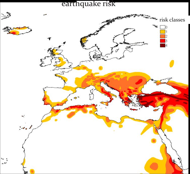
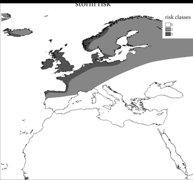
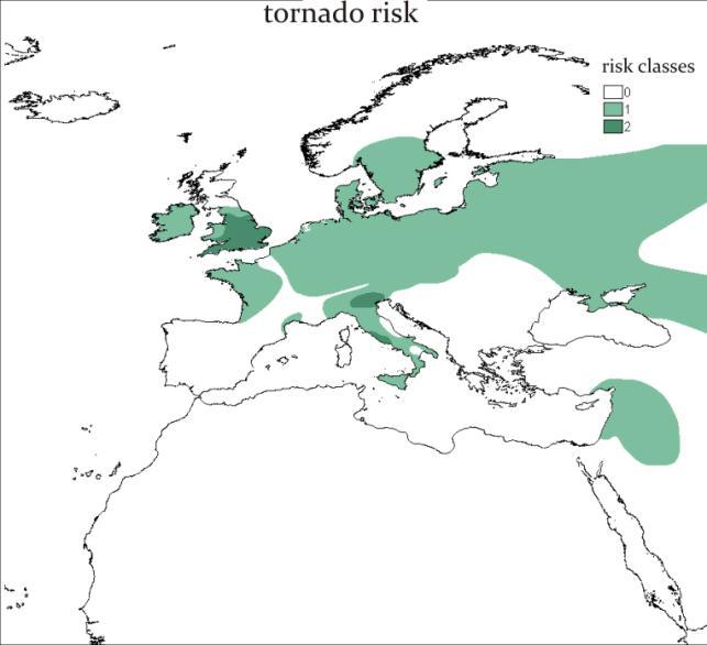
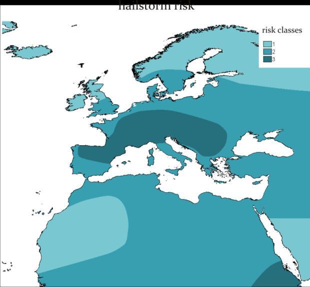
48 48
.")


49 Figure 39: Risk maps (Munich RE, cited from DLR 2009) The total transmission length is an additional criterion. That means, layouts with short total transmission line lengths have to be favoured (taking into account the exclusive criteria). All the mentioned exclusion and non-exclusion criteria can be taken into consideration in a quantitative model which allows calculating an optimized grid, in which all demand centres are connected to all plant sites, which avoids all exclusion areas and which provides an economically optimized layout taking into consideration all non-exclusive criteria. DLR designed such a quantitative model and calculated a line layout, which is illustrated in the following figure: Figure 40: Optimized HVDC grid between CSP sites in MENA and European consumption sites (source: DLR 2009, 124) 49
50 In the TRANS-CSP study, DLR considered the following possible roadmap for a long term development of HVDC transmission: HVDC cable interconnections are considered to have a capacity of 5000 MW, such that twenty interconnections are necessary to provide the total capacity of 100 GW, which would be necessary to realize the Desertec project (which was taken as reference project). Until 2050, the twenty transmission lines would be built with an investment volume of 45 Billion Euros. Taking into account that each transmission line needs a corridor of about 100m width, and considering an average length of 3600 km for the lines, the required land area would amount to 3600 square kilometers. Table 4: Possible development of the HVDC lines between MENA and Europe according to DLR 2006, Amplifying the EU-MENA super grid The illustrated supergrid is designed to transmit electricity from MENA to Europe, which is an economically favourable way to diversify the energy sources for Europe and which offers new economical perspectives for the MENA region. However, from a European point of view, it may be just one piece (although a very large and decisive one) in a wider context of an even bigger supergrid, which permits the interrelated usage of different distant energy resources such as, for instance, hydropower in Norway, wind in the North Sea, biomass in Central and Eastern Europe, geothermal resources in Italy and solar energy from the MENA countries. Such a supergrid is especially interesting taking into account the fact that some of these energy sources are fluctuating. HVDC transmission over long distances can contribute considerably to reach compensational effects through the combination of distant and different renewable energy resources and stabilize, hence, the electricity supply. While we transported until now the energy in form of oil, gas coal and uranium we will transport more and more electricity from the place where we can get it, i.e. hydropower from Scandinavia, wind power from the North Sea and solar energy from Africa. In a future supergrid, which will make this possible, HVDC highways could have a very important function. They will increase the redundancy and stability of the whole system. A future HVDC grid would primarily serve for long distance transfer and the conventional AC grids would have their traditional function of regional transport and local distribution. The HVDC grid would be like a highway grid for long distance transport with a low 50

51 number of inlets and outlets to the smaller roads, i.e. the conventional AC systems. The following figure shows the idea of such a supergrid which interconnects different distant energy sources. Figure 41: Use of HVDC lines to connect different energy sources in Europe and in the MENA region (source: Desertec Foundation) 51

52 4.4 Ownership Structure of Transnational Transmission Lines Until now, HVDC lines have been built for the transfer of electricity between two countries. The ownership of these interconnections is mostly organised as cooperation between the transmission system operators of the two connected countries. Contrary to that, there are no experiences with the ownership structures for transmission grids that cross other countries. The large-scale exports of solar electricity from MENA to Europe would require the transmission across other countries. To get an idea how the ownership of such a transmission line could be organized experiences from other energy sectors can be considered. A model could be, for instance, the Nabucco gas pipeline, which is going to be built between Asia (East Turkey) and Europe (Austria). Its ownership structure is the following: The pipeline will be situated in five countries running from Turkey via Bulgaria, Romania and Hungary to Austria. The owner is the Nabucco Gas Pipeline International GmbH. This company on its part belonged originally to the five companies that are active for the gas transport in each of the five countries. The German utility company RWE joined later as the sixth shareholder. The Nabucco Gas Pipeline International GmbH is responsible for the planning, financing, construction, marketing as well as the maintenance of the pipeline. It takes its decisions independently from its parent companies as an autonomous economic entity. 42 Another model could be the international public ownership of the HVDC grid and the national responsibility for the connected AC grids. Figure 42: Nabucco pipeline routing ( 42 See 52
53 5 Political, industrial and other initiatives for the development of the EU-MENA grid The development of an international grid structure is a very large infrastructure project. It requires huge investment volumes and is therefore an important economical challenge. As several countries are involved (potentially a large number), large international industrial consortia will be necessary. Additionally, like any large infrastructure project, it is a public issue, which makes necessary the involvement of political institutions. In the case of international grids, international political coordination is required. In this section, we will mention the different initiatives, which are important for the realization of a new grid structure in the Mediterranean. 5.1 Political and other non-industrial initiatives Euro-Mediterranean Partnership and Union for the Mediterranean The political cooperation between the EU and its Mediterranean neighbours got a firm impetus in November 1995 with the Euro-Mediterranean Partnership set up in Barcelona ( The Barcelona Process ). The Euro-Mediterranean partnership signed at the ministerial level in Barcelona was joined by the EU Member States and 12 partner countries around the Mediterranean: Algeria, Cyprus (EU member since 2004), Egypt, Israel, Jordan, Lebanon, Malta (EU member since 2004), Morocco, Palestinian Territories, Syria, Tunisia and Turkey. Libya had observer status. It covered a large range of policy areas in the Mediterranean basin: Political and Security Dialogue; Economic and Financial Partnership; Social, Cultural and Human Partnership. The Euro-Mediterranean Partnership was re-launched at the Paris Summit for the Mediterranean on 13 July 2008 under the French EU Presidency, when the Heads of State and governments of the European and Mediterranean countries founded the Union for the Mediterranean, which has the aim to promote a new form of cooperative partnership between the two shores of the Mediterranean Sea. The Union for the Mediterranean pays special attention to concrete projects, among which is the Mediterranean Solar Plan (MSP). The MSP does not only target solar energies, but aims at developing renewable energies in general, energy efficiency measures, the reinforcement of the power grid interconnections and the technology transfer in the Mediterranean region. It counts with the participation of all member states of the Union for the Mediterranean as well as firms, investors, financial institutions and other organizations interested in the project. The MSP addresses both supply and demand and it has the following mid-term guidelines: 1) to develop 20 GW of new renewable energy generation capacities on the South shore of the Mediterranean by ) to achieve 20% energy savings around the Mediterranean by 2020 in comparison to a business-as-usual scenario. A high priority shall be given to the exploitation of the enormous potential of solar electricity generation in the Mediterranean countries, notably through the development of PV and CSP plants, and of other available and mature renewable energy technologies. Additionally, the setup of a common framework in terms of legal, regulatory and investment environment for the development of new generation capacity from solar and other renewable energy sources (especially wind) in the countries around the Mediterranean Sea is an important topic. 53
54 The MSP faces first the satisfaction of the growing local electricity demand in the countries under consideration, but also the export to Europe is foreseen. A regulatory framework for importing electricity to the EU from non-eu countries is already in place, thanks to the possibility of so-called joint projects, established in article 9 of the Directive 2009/28/EC on the promotion of the use of energy from renewable sources. This Directive still has to be translated into national legislation in the EU member states in order to enter in effect Desertec Foundation In 2003 the Club of Rome 44, the Hamburg Climate Protection Fund and the National Energy Research Centre of Jordan founded the Trans-Mediterrranean Renewable Energy Cooperation (TREC). TREC developed the Desertec concept. The principal idea is to generate electricity in the deserts around the world. CSP plants, PV plants as well as wind power plants are considered. However, CSP technology plays a central role in the concept because it provides firm capacity and power on demand. Scientific research about Desertec was done principally by DLR. On 20 th January 2009 the non-profit Desertec Foundation emerged from TREC. It was established in Berlin in order to promote the implementation of the concept of clean power from deserts around the world. Founding members are the German Association of the Club of Rome, members of an international network of scientists as well as committed private individuals. The Desertec Foundation was one of the driving forces in the creation of the industrial initiative Dii (see below). In the meantime, the Desertec idea has found approval in politics. The European Commission supports it 45 and also the new Energy Plan of the German Government mentions explicitly the Desertec project. The German Government will collaborate with the Union for the Mediterranean and the EU commission to develop a strategy to realize the MSP of the Union for the Mediterranean and to identify the conditions for the realization of the Desertec project. Feasibility studies and an enhanced international dialogue about energy and developmental topics are envisaged Industrial initiatives MEDELEC At the beginning of the 1990s MEDELEC (Mediterranean Committee for Electricity) was founded to foster the dialog between the transmission system operators of the different regions. The organizations taking part are the UCTE, COMELEC, AUPTDE, UPDEA (see above) as well as EURELECTRIC and OME. EURELECTRIC, the Union of the Electricity Industry, is the sector association which represents the common interests of the electricity industry at European level, plus its affiliates and associates on 43 See med-emip 2010, vol. 2. The Directive can be found at 44 The Club of Rome is a non-commercial organization that pursues a global debate about different global political questions. It was founded in 1968 and its office is located in Winterthur (Switzerland). Members are scientists, economists, industrialists and other public persons informes about that. 46 See BMWI/BMU


55 other continents. It was created in its actual form in 1999 by the integration of forerunner institutions. 47 OME, the Observatoire Méditerranéen de l Énergie, was created in It is an association of direct or indirect players in the production, transport or distribution of energy as well as in the research about the future of energy in the Mediterranean that has the main purpose to promote cooperation and collaboration between organizations and enterprises in the energy sector, notably within the framework of the Euro-Mediterranean partnership. 48 The aim of MEDELEC is to agree on a technical standard that will provide the necessary stability for an interconnected electricity network around the Mediterranean Dii In October 2009 the industrial initiative Dii was created under German law as a GmbH (limited liability company) with shareholders from the industrial and finance sector. It was co-initiated by the Desertec Foundation. In the first time it had the name Desertec Industrial Initiative, but changed later to Dii in order to avoid confusion with the non-commercial Desertec Foundation. The shareholder companies are from different European and North African countries. The mission of Dii is to enable the roll-out of the Desertec concept for EU-MENA, i.e. the concept that aims at supplying MENA and Europe with power produced from solar and wind energy in the deserts. The long term goal is to satisfy a substantial part of the energy needs of the MENA countries and to meet about 15% of Europe s electricity demand by Figure 43: Industrial and non-industrial initiatives for the realisation of large-scale energy exchange between Europe and MENA 47 See 48 See 49 From See also 55

56 5.2.3 Medgrid Like the Union for the Mediterranean, which was established under the French presidency in the European Union, Medgrid was initiated by French entities. It was created in May 2010 under the name Transgreen, which was later changed to Medgrid. Like Dii it is an industrial initiative. Similarly to Dii, which changed from a German dominated initiative to a truly international enterprise (although under German legislation), Medgrid is now understood as a consortium open to companies from different European as well as North African and Middle East countries. While Dii focuses on the realization of the Desertec concept in the EU-MENA region in general, Medgrid concentrates on the planning and implementation of the power line network between the MENA region and Europe. Medgrid and Dii may appear to be competitors. However, both sides have announced strong cooperation and excellent interaction with each other on the working level. Medgrid considers as its most urgent work the study of the feasibility of laying a network of HVDC undersea power lines. These studies shall be accomplished until It bases its work on the MSP, especially on the plan to develop 20 GW of new renewable energy generation capacities by It calculates with a necessary investment of 6 Billion Euros in grid infrastructure (grid access and new transmission lines), while the total cost of the realization of the MSP is estimated to be 38 to 46 Billion Euros. Medgrid assumes that only 5 GW of the 20 GW will be exported to Europe, while the other 15 GW will be used to satisfy the growing electricity demand in the MENA countries themselves. Figure 44: Medgrid and its central working assumptions The concrete tasks are formulated as the following: 1) to propose technical and economical guidelines for the installation of a trans-mediterranean transmission grid, which is capable to transmit 5 GW from MENA to Europe by ) to pursue a regulatory and institutional framework, which is favourable for the respective investments in MENA (feed-in tariffs, sale of carbon certificates, fiscal incentives) 50 See 56
 to promote European industry and its technology, especially concerning energy generation on the")
57 3) to evaluate the benefits of the infrastructure investments and the electricity exchanges in relation to economic activities and growth, and to employment 4) to develop technical and technological cooperation with MENA countries by means of electrical connection projects in the Mediterranean 5) to promote European industry and its technology, especially concerning energy generation on the basis of renewable energy sources, DC transmission and ultra-high voltage sea cables. The following companies, which are electricity suppliers and handlers and manufacturers of high voltage equipment, are the founding members of Medgrid: Figure 45: Medgrid - participating companies 57
Improving the integration of electricity networks: Prospects of the European Network of Transmission System Operators for Electricity (ENTSO-E)
") Improving the integration of electricity networks: Prospects of the European Network of Transmission System Operators for Electricity (ENTSO-E) 1. Context: ENTSO-E, 10/20/40 year views, network codes 2.
Improving the integration of electricity networks: Prospects of the European Network of Transmission System Operators for Electricity (ENTSO-E) 1. Context: ENTSO-E, 10/20/40 year views, network codes 2.
Interconnection between Arab countries
 Interconnection between Arab countries Eng. Fawzi Kharbat Secretary General AUE Enabling renewable energy in the electricity systems workshop 16 April 2014 Tunis 1 Arab Union of Electricity Date of Establishment:
Solar Electricity for Regional Consumption or Export: Which way to lean?
 6/1/21 Euro-Mediterranean Energy Market Integration Project Germany France Lebanon Belgium Solar Electricity for Regional Consumption or Export: Which way to lean? Dr. Albrecht Kaupp Team Leader The contents
Power import, transboundary connections, Market Coupling. Grzegorz Onichimowski President of the Board, TGE S.A.
 Power import, transboundary connections, Market Coupling Grzegorz Onichimowski President of the Board, TGE S.A. Power import, transboundary connections, Market Coupling Conference Power Ring, December_2008
Click to edit title 18. Fachforum Netzbau und Betrieb
 The North Sea Off-Shore Grid a Vision to be Realised? Click to edit title 18. Fachforum Netzbau und Betrieb Köln, Click to 6.-7. edit Mai sub-title 2010 Dr. Matthias Luther transpower stromübertragungs
Enabling DESERTEC in EUMENA
 Dii GmbH Enabling DESERTEC in EUMENA Rene Buchler Chairman Siemens S.A. Tunisia Dii - Our way to enable DESERTEC in EUMENA / Page 1 Plans to produce power in the desert are not new Solar history Frank
Innovative technologies ready for the Supergrid
 Innovative technologies ready for the Supergrid The Roadmap to the Supergrid Technologies EEF lunchtime discussion Feb 6, 2013 in Strasbourg Presented by Dr. Magnus Callavik, ABB (Convenor of WG 2 - Technology)
Renewable Energy Development in the Mediterranean Region Renewable Energy Investments In The Mediterranean And Beyond
 Dott. Matteo Codazzi Milano, 30.10.2017 Renewable Energy Development in the Mediterranean Region Renewable Energy Investments In The Mediterranean And Beyond Milano, CESI has a solid track record in RES
The future role of storage in a smart and flexible energy system
 The future role of storage in a smart and flexible energy system Prof Olav B. Fosso Dept. of Electric Power Engineering Norwegian University of Science and Technology (NTNU) Content Changing environment
Regional Cooperation Infrastructure Development and Operation. EU Energy Governance. Olaf Ziemann Member of ENTSO-E s System Operations Committee
 Regional Cooperation Infrastructure Development and Operation EU Energy Governance 30 April 2014, Berlin Olaf Ziemann Member of ENTSO-E s System Operations Committee About ENTSO-E 41 TSOs from 34 countries
European Power Markets. Jukka Ruusunen President and CEO
 European Power Markets President and CEO Fortum's Capital Markets Day Stockholm, Sweden 5-6 th 2 Driver for the development: European energy policy goals Energy future is: more sustainable - towards carbon
Tibin Joseph Marie Curie Early Stage Researcher Institute of Energy Cardiff University
 Tibin Joseph Marie Curie Early Stage Researcher Institute of Energy Cardiff University Contents Introduction Planned Network Reinforcement for 2020 The Three Machine Generic Model Subsynchronous Resonance
HVDC Transmission: Part of the Energy Solution? Peter Hartley Economics Department & James A. Baker III Institute for Public Policy, Rice University
 HVDC Transmission: Part of the Energy Solution? Peter Hartley Economics Department & James A. Baker III Institute for Public Policy, Rice University Why has HVDC taken off? HV is needed to transmit DC
The Proposed Electricity Directive and Regulation: Market Design for a Low-Carbon Electricity Sector
 The Proposed Electricity Directive and Regulation: Market Design for a Low-Carbon Electricity Sector Mediterranean Forum on Electricity and Climate Change The Clean for All Europeans Package & Mediterranean
The Electric Power System
 The Electric Power System INDIA Indian Power System 1 2 Basic facts Area:3.288 million km² Population:1.25 Billion Electricity consumers: 216 Million- (31.3.2013) Number of TSOs: 14- (31.3.2013) Numbe
European Wind Integration Study (EWIS) Towards a Successful Integration of Wind Power into European Electricity Grids
 Towards a Successful Integration of Wind Power into European Electricity Grids") European Wind Integration Study (EWIS) Towards a Successful Integration of Wind Power into European Electricity Grids EWIS Concluding Discussion 13th April 2010, Brussels Network Strengthening findings
European Wind Integration Study (EWIS) Towards a Successful Integration of Wind Power into European Electricity Grids EWIS Concluding Discussion 13th April 2010, Brussels Network Strengthening findings
DG system integration in distribution networks. The transition from passive to active grids
 DG system integration in distribution networks The transition from passive to active grids Agenda IEA ENARD Annex II Trends and drivers Targets for future electricity networks The current status of distribution
Northern European power system scenarios for EMPS 2010 to 2030
 Stefan Jaehnert Northern European power system scenarios for EMPS 21 to 23 Brukermøte Produksjonsplanlegging 22. Mai 213 1 Outline 1. Basic modelling assumption Northern Europe 2. 23 scenario development
India Smart Grid Week, 2017
 India Smart Grid Week, 2017 N. Venu President and Head, Power Grids Division, South Asia, Middle East and Africa ABB 1 Big Shift in Power: Shaping the System of the Future Several global challenges Population
Effects of Smart Grid Technology on the Bulk Power System
 Effects of Smart Grid Technology on the Bulk Power System Rana Mukerji Senior Vice President Market Structures New York Independent System Operator Union College 2013 Environmental Science, Policy & Engineering
Electricity markets in Europe : EDF s experience 14/10/2005 EDF-DPI-EPSI
 Electricity markets in Europe : EDF s experience 1 A BIT OF HISTORY Electricity market was liberalized in the U.K during the eighties. Then a wide discussion was launched at European level. Finally, a
The Swedish Government Inquiry on Smart Grids
 The Swedish Government Inquiry on Smart Grids Math Bollen Athens, Greece, 18 December 2010 Smart grid inquiry What are smart grids? Why do we need smart grids? State of deployment and development Conclusions
Asia International Grid Connection Study Group Interim Report
 Asia International Grid Connection Study Group Interim Report Table of Contents Chapter 1:Basic Concept of an International Power Grid Purposes of the international power grid Diplomatic relations concerning
Security of Supply. on the European Electricity Market
 Security of Supply on the European Electricity Market What is Security of Supply? A reliable supply of energy Reliable transportation of supply Reliable distribution and delivery of supply to the final
North-South Interconnections in Central-East and South- East Europe
 European Network of Transmission System Operators for Electricity North-South Interconnections in Central-East and South- East Europe Building power bridges between Eastern and Western Europe; relieving
The Role of DSO as Facilitator of the Electricity Markets in Macedonia. Key aspects and considerations
 The Role of DSO as Facilitator of the Electricity Markets in Macedonia Key aspects and considerations 30 th of May, 2017 Renewable Energy Production in Macedonia (1/5) Supportive Measures Installed capacity
GLOBAL ELECTRICITY PRICES
 Q3 2018 GLOBAL ELECTRICITY PRICES GPP Quarterly Report GLOBALPETROLPRICES.COM September 2018 OVERVIEW In September 2018, households around the world paid 0.154 USD for a kwh of electricity. That average
Smart Grids and Integration of Renewable Energies
 Chair of Sustainable Electric Networks and Sources of Energy Smart Grids and Integration of Renewable Energies Professor Kai Strunz, TU Berlin Intelligent City Forum, Berlin, 30 May 2011 Overview 1. Historic
Next Generation of UHVDC System. R. Montaño, D Wu, L. Arevalo, B. Jacobson ABB - HVDC Sweden
 Conference-1 Latest Technologies in T & D, Renewable Energy Integration, Smart Grid, Energy Efficiency, Communication Next Generation of UHVDC System R. Montaño, D Wu, L. Arevalo, B. Jacobson ABB - HVDC
Implementation of a Wide Area Monitoring System (WAMS) for Austria's Power Grid
 for Austria's Power Grid") Implementation of a Wide Area Monitoring System (WAMS) for Austria's Power Grid Dr. Michael Weixelbraun Austrian Power Grid AG (APG) International Synchrophasor Symposium, March 22-24, 2016 1 Austrian
Implementation of a Wide Area Monitoring System (WAMS) for Austria's Power Grid Dr. Michael Weixelbraun Austrian Power Grid AG (APG) International Synchrophasor Symposium, March 22-24, 2016 1 Austrian
NEW ENERGY -4- MOBILITY TECHNOLOGIES
 April 2017 Anne Kleczka; BMW Group Hannover Fair 2017 BMW TECHNOLOGY FOCUS AREAS. BMW Group Technology Focus Areas. Powertrain Digitalization Efficient Dynamics NEXT E-Drive Hydrogen Connectivity Artificial
The Global Grid. Prof. Damien ERNST
 The Global Grid Prof. Damien ERNST Energy needs of the planet: a few numbers Yearly world energy consumption (2016): 155,000 TWh Average energy needs per person per day: 56 kwh Energy consumption the US:
Introduction to transmission network characteristics - technical features. Slobodan Markovic EKC Athens,
 Introduction to transmission network characteristics - technical features Slobodan Markovic EKC Athens, 06.03.2017 1 MAIN ISSUES The map shows the region that will be included in the network modelling
WESTERN INTERCONNECTION TRANSMISSION TECHNOLGOY FORUM
 1 1 The Latest in the MIT Future of Studies Recognizing the growing importance of energy issues and MIT s role as an honest broker, MIT faculty have undertaken a series of in-depth multidisciplinary studies.
The role of Transmission System Operator in Belgium and in Europe. Vlerick Alumni Event 26 January 2016
 The role of Transmission System Operator in Belgium and in Europe Vlerick Alumni Event 26 January 2016 Agenda Introduction Infrastructure management Controlling the system Developing the EU Market 1/25/2016
Climate change drivers for a single and smart EU grid
 Climate change drivers for a single and smart EU grid Smart and Secure Transmission Grids to Realise US and EU Renewable Energy Potentials Keith Bell University of Strathclyde, Scotland Expected growth
Electricity Networks Inter-regional market co-ordination (Session 8)
") Electricity Networks Inter-regional market co-ordination (Session 8) Dennis Volk Electricity Analyst Electricity System Training Week, Bangkok, November 2013 Theoretical benefits of inter-regional approaches
Electricity Networks Inter-regional market co-ordination (Session 8) Dennis Volk Electricity Analyst Electricity System Training Week, Bangkok, November 2013 Theoretical benefits of inter-regional approaches
SET Plan The 10th Year Anniversary Central European Energy Conference 2017
 MARKET COUPLING: UKRAINIAN WAY SET Plan The 10th Year Anniversary Central European Energy Conference 2017 UKRENERGO 2 TRANSMISSION COMPANY (state-owned, consists of 8 regional systems) Substations 137
SOLAR GRID STABILITY
 SMART RENEWABLE HUBS FOR FLEXIBLE GENERATION SOLAR GRID STABILITY Smart Renewable Hubs: Solar hybridisation to facilitate Renewable Energy integration COBRA, IDIE, TECNALIA, CESI, HEDNO, NTUA 7 th Solar
RENEWABLE ENERGY TRANSMISSION INTERCONNECTION. Line Tveter
 RENEWABLE ENERGY TRANSMISSION INTERCONNECTION Line Tveter ltveter@kentlaw.edu Roadmap A. The Norwegian Electricity Sector The Basics B. The Norwegian Electricity Grid Organization and Regulation C. Grid
SMART DIGITAL GRIDS: AT THE HEART OF THE ENERGY TRANSITION
 SMART DIGITAL GRIDS: AT THE HEART OF THE ENERGY TRANSITION SMART DIGITAL GRIDS For many years the European Union has been committed to the reduction of carbon dioxide emissions and the increase of the
Electricity industry structure and key players
 Electricity industry structure and key players Growth in capacity, production and consumption, 2006 2017 Expected demand and addition to generation capacity, 2018 2027 Growth in transmission network and
NURZAT MYRSALIEVA. Distributed solar technologies: trends and scenarios in the Mediterranean Region
 NURZAT MYRSALIEVA Distributed solar technologies: trends and scenarios in the Mediterranean Region About RCREEE Independent regional inter-governmental organization 16 member states National focal point
The role of electricity in the clean energy transition
 The role of electricity in the clean energy transition Laszlo Varro, Chief Economist Annual Conference Federation of Danish Energy Industries, 26 April 2018 IEA On the journey towards a clean energy system
Dr.-Ing. Ervin Spahi, Wadden Sea Forum, Bremerhaven Electric grid on and off-shore: current status, obstacles and new developments
 Dr.-Ing. Ervin Spahi, Wadden Sea Forum, Bremerhaven 26.11.09 Electric grid on and off-shore: current status, obstacles and new developments November 26, 2009 Slide 1 Transmission grid The challenges Optimal
Energy Economics. Lecture 6 Electricity Markets ECO Asst. Prof. Dr. Istemi Berk
 Energy Economics ECO-4420 Lecture 6 Electricity Markets Asst. Prof. Dr. Istemi Berk istemi.berk@deu.edu.tr 1 Electricity Markets An Introduction Electricity secondary energy source generated from different
Controlling weather-dependent renewable electricity production with blockchain
 IT 13 Turning electric cars and household batteries into distributed energy sources Controlling weather-dependent renewable electricity production with blockchain 2 14 How can IT make our world more sustainable,
Long distance bulk transmission
 Long distance bulk transmission Dr. Yanny Fu, KEMA Consulting 6 October 2010 Experience you can trust. 2 Contents Transmission technologies AC and DC Overhead lines and underground/submarine cables Transmission
Energy Challenges and Costs for Transport & Mobility. 13th EU Hitachi Science and Technology Forum: Transport and Mobility towards 2050
 Energy Challenges and Costs for Transport & Mobility 13th EU Hitachi Science and Technology Forum: Transport and Mobility towards 25 Dr. Lewis Fulton Head, Energy Policy and Technology, IEA www.iea.org
Europe's first blockchain project to stabilize the power grid launches: TenneT and sonnen expect results in 2018
 Press release Europe's first blockchain project to stabilize the power grid launches: TenneT and sonnen expect results in 2018 TenneT uses decentralized home energy storage systems networked via blockchain
An overview of HVDC market and future outlook. Saqib Saeed Principal Analyst Power Technology Research LLC (PTR)
") An overview of HVDC market and future outlook Saqib Saeed Principal Analyst Power Technology Research LLC (PTR) Agenda Global overview of HVDC market Specifics of growing HVDC markets Manufacturer profiles
An overview of HVDC market and future outlook Saqib Saeed Principal Analyst Power Technology Research LLC (PTR) Agenda Global overview of HVDC market Specifics of growing HVDC markets Manufacturer profiles
The electrical system: the very fundamentals
 The electrical system: the very fundamentals The material of this presentation is entirely based on teaching material developed by prof. Thierry Van Cutsem Objectives Show the overall structure of an electric
Course notes for EE394V Restructured Electricity Markets: Locational Marginal Pricing
 Course notes for EE394V Restructured Electricity Markets: Locational Marginal Pricing Ross Baldick Copyright 2018 Ross Baldick www.ece.utexas.edu/~baldick/classes/394v/ee394v.html 1 1 Recent History of
BRIEF POLICY. Thoughts on an Electricity System and Grid Paradigm Shift in Response to the EU Energy Transition and the Clean Energy Package
 Issue 2018/19 October 2018 Thoughts on an Electricity System and Grid Paradigm Shift in Response to the EU Energy Transition and the Clean Energy Package By Olivier Lavoine, Florence School of Regulation
Power Conditioning of Microgrids and Co-Generation Systems
 Power Conditioning of Microgrids and Co-Generation Systems Nothing protects quite like Piller piller.com Content 1 Introduction 3 2 Basic requirements of a stable isolated network 3 3 Requirements for
Opportunities for Export and Trade Development: Electricity Export Expansion to Europe. Joint EFET & DTEK Legal Workshop
 Opportunities for Export and Trade Development: Electricity Export Expansion to Europe Joint EFET & DTEK Legal Workshop March 2012 Electricity export: history and nowadays Ukraine provides electricity
The Electric Power System
 The Electric Power System - Sweden- Swedish Power System 1 2 Basic facts 2014 Area: 450 295 km 2 Population: 9.6 Million Number of electricity consumers: 5.3 Million Number of TSOs: 1 Number of DSOs: 170
ESIA Study for 1,050MW Coal Fired Power Plant, Lamu County, Kenya Need for the Project. 3 Need for the project... 2
 Contents 3 Need for the project... 2 3.1. Project Background... 2 3.2. Energy mix and demand forecast... 2 3.3. 5000+ Project... 4 List of tables Table 3-1: Electric power generation sources and energy
Net Metering in Missouri
 Net Metering in Missouri Make A Good Policy Great (AGAIN) Executive Summary More and more Americans every year are able to produce their own electricity. As the cost of solar continues to plummet, homeowners
4th European PV-Hybrid and Mini-Grid Conference, Glyfada, Greece, May 2008
 Stability in Mini-Grids with Large PV Penetration under Weather Disturbances- Implementation to the power system of Kythnos Evangelos Rikos 1, Stathis Tselepis 1, Aristomenis Neris 2 1. Centre for Renewable
HVDC Innovative Technology for Smart Grids and Super Grids. Wilfried Breuer CEO Power Transmission Solutions, Siemens Energy Sector
 HVDC Innovative Technology for Smart Grids and Super Grids CEO Power Transmission Solutions, Siemens Energy Sector BritNed: Pre-launch Press Event Maasvlakte, March 31, 2011 Siemens AG 2011 Energy Sector
Modelling Analysis for Optimal Integration of Solar PV in National Power Grid of Japan
 USAEE/IAEE 36th North American Conference, Concurrent Session 28, Hilton Crystal City, Washington DC USA, September 25, 2018 Modelling Analysis for imal Integration of Solar PV in National Power Grid of
EUROPEAN GRID CONFERENCE European Parliament Brussels:
 EUROPEAN GRID CONFERENCE European Parliament Brussels: Grid Infrastructure: Super, Smart or SuperSmart? by Konstantin Staschus, Ph.D. 10 November 2011 Secretary-General of ENTSO-E konstantin.staschus@entsoe.eu
Transmission System Operators in the Interplay between Physics and Market
 Session 02: Large Scale Renewables Integration and the Changing Roles of TSO and DSO Companies Transmission System Operators in the Interplay between Physics and Market DI Mag.(FH) Gerhard Christiner Chief
Transmission Grid Development & Investment Planning on EHV Level in Germany
 Transmission Grid Development & Investment Planning on EHV Level in Germany February, 27th, 2018 Michael Jesberger 1 Kilometer (km) = 0,602 miles 1 Euro = 1,22 $ (Februry, 8th, 2018) March 2016 TenneT
ABB POWER SYSTEMS CONSULTING
 ABB POWER SYSTEMS CONSULTING DOMINION VIRGINIA POWER Offshore Wind Interconnection Study 2011-E7406-1 R1 Summary Report Prepared for: DOMINION VIRGINIA POWER Report No.: 2011-E7406-1 R1 Date: 29 February
Prospects of HVDC and FACTS for Sustainability and Security of Power Supply
 Prospects of HVDC and FACTS for Sustainability and Security of Power Supply Advances in Power System Control, Operation and Management APSCOM, 8 th 11 th of November 2009, Hong Kong Wilfried Breuer, CEO
HVDC Interconnectors Benefits and Challenges
 HVDC Interconnectors Benefits and Challenges Electric Power Control Center Workshop Bled, Slovenia 18th May 2015 Ole Gjerde Content of Presentation Background Experience Benefits Challenges Future A Changing
Robustness and Cost Efficiency through User Flexibility in the Distribution Network
 Washington, April 20, 2015 Robustness and Cost Efficiency through User Flexibility in the Distribution Network Knut Samdal, Research Director SINTEF Energy Research knut.samdal@sintef.no 1 SINTEF is the
Nordic co-operation when meeting System challenges
 Nordic co-operation when meeting System challenges Evolving the market conference Ulla Sandborgh CEO Agenda > System challenges > System development plan > Strategies > Grid development > Tariff development
The 6 th Basic Plan for Long-term Electricity Supply and Demand (2013~2027)
") The 6 th Basic Plan for Long-term Electricity Supply and Demand (2013~2027) February 2013 Contents I. Introduction 1 II. Status of Electricity Supply and Demand 2 1. Electricity Demand 2 2. Electricity
The 6 th Basic Plan for Long-term Electricity Supply and Demand (2013~2027) February 2013 Contents I. Introduction 1 II. Status of Electricity Supply and Demand 2 1. Electricity Demand 2 2. Electricity
Data Centres Using resources to support grid systems Another revenue stream?
 Data Centres Using resources to support grid systems Another revenue stream? Russell Bulley Technical Support Manger March 2019 Russell.bulley@vertivco.com 2018 Vertiv 2 GLOBAL ELECTRICITY GENERATION &
The Romanian Grid a Hub for Regional Electricity Markets in SEE
 The Romanian Grid a Hub for Regional Electricity Markets in SEE Adrian Baicusi General Director T RANSELECT RICA Marian Cernat, Director of NDC Operational Division - T RANSELECT RICA Hub of Regional Market
PLANNING, ELIGIBILITY FOR CONNECTION AND CONNECTION PROCEDURE IN EMBEDDED GENERATION
 PLANNING, ELIGIBILITY FOR CONNECTION AND CONNECTION PROCEDURE IN EMBEDDED GENERATION Presentation by Engr. O. C. Akamnnonu Chief Executive Officer, Ikeja Electricity Distribution Company AGENDA WORK THROUGH
Accommodating High Levels of Variable Generation. EPRI Managing Complexity for Safety and Reliability September 14-15, 15, 2009
 Accommodating High Levels of Variable Generation EPRI Managing Complexity for Safety and Reliability September 14-15, 15, 2009 Agenda About NERC About the Integration of Variable Generation Task Force
Eric Johnson, Director, External Affairs, ISO New England
 To: From: NECPUC and NESCOE Eric Johnson, Director, External Affairs, ISO New England Date: January 22, 2016 Subject: How Energy Storage Can Participate in New England s Wholesale Electricity Markets Interest
I remind you that our presentation is available on our website. We can start from the first 2 slides that show Piaggio Group First
 CONFERENCE CALL 2009 1 st HALF RESULTS Good afternoon and welcome to everybody. I remind you that our presentation is available on our website. We can start from the first 2 slides that show Piaggio Group
Renewables from a TSO Perspective. M.BENA, SmartGrids Director, RTE, French TSO Vienna, 18 May 2015
 Renewables from a TSO Perspective M.BENA, SmartGrids Director, RTE, French TSO Vienna, 18 May 2015 RTE in Europe 8500 employees Owner and Operator of the Assets 100 000 km UHV and HV lines (400 kv -> 63
Table of Contents... i List of Tables... vi List of Figures... x List of Abbreviations... xiv
 Table of Contents Table of Contents Table of Contents... i List of Tables... vi List of Figures... x List of Abbreviations... xiv Introduction... 1 Operating Support Incentives... 1 Feed-in Tariffs...
Case study The impact of variable Renewable Energy Sources on the European Power System
 Case study The impact of variable Renewable Energy Sources on the European Power System ICER GO15 Joint Workshop Managing the Needs of Investments Resulting from Energy Transition D. Dobbeni London, April
Technology from the New Product SANUPS K for a Smart Grid Society
 Features: Technology Contributing to Effective Use of Power Technology from the New Product SANUPS K for a Smart Grid Society Yoshiaki Okui 1. Introduction After the Tohoku Earthquake, there is a movement
northeast group, llc Southeast Asia Smart Grid: Market Forecast ( ) Volume II October group.com
 Volume II October group.com") northeast group, llc Southeast Asia Smart Grid: Market Forecast (2014 2024) Volume II October 2014 www.northeast- group.com Southeast Asia Smart Grid: Market Forecast (2014-2024) Southeast Asia is a growing
northeast group, llc Southeast Asia Smart Grid: Market Forecast (2014 2024) Volume II October 2014 www.northeast- group.com Southeast Asia Smart Grid: Market Forecast (2014-2024) Southeast Asia is a growing
STATUS OF CROSS BORDER TRADE AND ENERGY MARKET NEPAL-INDIA EXCHANGE
 STATUS OF CROSS BORDER TRADE AND ENERGY MARKET NEPAL-INDIA EXCHANGE South Asia Regional Workshop on Policies and Regulations to Increase Cross Border Energy Trade ( February 15-17,2012; New Delhi) RAM
Chapter 1. Overview of HVDC applications
 ELEC0445 - High Voltage Direct Current grids Part 1. Line Commutated Converters Chapter 1. Overview of HVDC applications Patricia Rousseaux t.vancutsem@ulg.ac.be Thierry Van Cutsem www.montefiore.ulg.ac.be/~vct
PV HYBRID INDUSTRIAL MICROGRIDS IN UNRELIABLE NATIONAL GRIDS
 AALBORG 2015 Symposium on Microgrids, REMOTE session 27 and 28 August 2015 PV HYBRID INDUSTRIAL MICROGRIDS IN UNRELIABLE NATIONAL GRIDS Xavier VALLVÉ, María ANZIZU and Marilena LAZOPOULOU Trama TecnoAmbiental,
Final Written Examination.
 Benha University Semester (3 th year Power &Control) Faculty of Engineering Electrical Power Systems (E1331) Electrical Engineering Department Semester 2015-2016 Final Written Examination. 10/1/2016 Time
Experience on Realizing Smart Grids. IEEE PES conference, Gothenburg
 Experience on Realizing Smart Grids Bazmi Husain 2010-10-12 IEEE PES conference, Gothenburg IEEE PES Conference, Gothenburg, 2010-10-12. Slide 1 On the way to the smarter grid A quietly astounding evolution
northeast group, llc Central & Eastern Europe Smart Grid: Market Forecast ( ) April group.com
 April group.com") northeast group, llc Central & Eastern Europe Smart Grid: Market Forecast (2013 2023) April 2013 www.northeast- group.com Central & Eastern Europe Smart Grid: Market Forecast (2013-2023) Countries in the
northeast group, llc Central & Eastern Europe Smart Grid: Market Forecast (2013 2023) April 2013 www.northeast- group.com Central & Eastern Europe Smart Grid: Market Forecast (2013-2023) Countries in the
Click to edit Master title style
 Challenges in grid planning and market integration moving towards the digital energy shift Trondheim, 28 April 2017 Information Technology and Electrical Engineering the digital energy shift Click to edit
Making electricity billing fair
 Making electricity billing fair How Alberta s billing system disadvantages small solar generators by Barend Dronkers and Sara Hastings-Simon June 2017 Summary The rules in Alberta governing the billing
Frequency Quality in the Nordic system: Offshore Wind variability, Hydro Power Pump Storage and usage of HVDC Links
 Frequency Quality in the Nordic system: Offshore Wind variability, Hydro Power Pump Storage and usage of HVDC Links by Atsede G. Endegnanew Hossein Farahmand Daniel Huertas-Hernando SINTEF Energy Research
-Mobility Solutions. Electric Taxis
 -Mobility Solutions Electric Taxis This paper was prepared by: SOLUTIONS project This project was funded by the Seventh Framework Programme (FP7) of the European Commission Solutions project www.uemi.net
The Development of Competitive Renewable Energy Zones in Texas
 The Development of Competitive Renewable Energy Zones in Texas Warren Lasher Manager, System Assessment 4/23/2008 North American Electric Grids The ERCOT Region is one of 3 NERC grid interconnections.
A complete transformation of the system as we know it
 A complete transformation of the system as we know it April 29, 2011 By Ron van Duuren and Karel Beckman There is widespread agreement among energy experts that a transition to a low-carbon future will
Getting Smart Evolution to the Smart Grid April 2008
 Getting Smart Evolution to the Smart Grid April 2008 Thomas F Garrity Vice President, Sales and Business Development Siemens Power T&D, Inc. Electrical energy is the backbone of our society Page 2 Mar-07
The research of power interconnection among China, Russia, Mongolia
 The research of power interconnection among China, Russia, Mongolia CONTENTS Part1 Brief introduction of Inner Mongolia grid Part2 The research of grids interconnection among China, Russia, Mongolia Part1
PV inverters in a High PV Penetration scenario Challenges and opportunities for smart technologies
 PV inverters in a High PV Penetration scenario Challenges and opportunities for smart technologies Roland Bründlinger Operating Agent IEA-PVPS Task 14 UFTP & IEA-PVPS Workshop, Istanbul, Turkey 16th February
Drivers, Building Blocks (Cables, Offshore), EU and US Examples, Grid- Enabled HVDC, LCC-MTDC
, EU and US Examples, Grid- Enabled HVDC, LCC-MTDC") Dr. Magnus Callavik, Power Systems HVDC, Aug 29, 2011 Developments in Multiterminal HVDC Drivers, Building Blocks (Cables, Offshore), EU and US Examples, Grid- Enabled HVDC, LCC-MTDC EPRI s High Voltage
Dr. Magnus Callavik, Power Systems HVDC, Aug 29, 2011 Developments in Multiterminal HVDC Drivers, Building Blocks (Cables, Offshore), EU and US Examples, Grid- Enabled HVDC, LCC-MTDC EPRI s High Voltage
Power and Energy (GDS Publishing Ltd.) (244).
 (244).") Smart Grid Summary and recommendations by the Energy Forum at the Samuel Neaman Institute, the Technion, 4.1.2010 Edited by Prof. Gershon Grossman and Tal Goldrath Abstract The development and implementation
Smart Grid Summary and recommendations by the Energy Forum at the Samuel Neaman Institute, the Technion, 4.1.2010 Edited by Prof. Gershon Grossman and Tal Goldrath Abstract The development and implementation
Advanced Active And Reactive Power Control For Mini Grids
 RIO 9 - World Climate & Energy Event, 17-19 March 2009, Rio de Janeiro, Brazil Advanced Active And Reactive Power Control For Mini Grids Stratis Tapanlis and Michael Wollny SMA Solar Technology AG Sonnenallee