CPS SC Series Grid-tied PV Inverter CPS SC100KT-O/US-480. Version: 1.1
|
|
|
- Cuthbert Jerome Wilkins
- 6 years ago
- Views:
Transcription


1 CPS SC Series Grid-tied PV Inverter CPS SC100KT-O/US-480 Version: 1.1
2 CHINT POWER SYSTEMS AMERICA CO., LTD. Address: 700 International Parkway, Suite 102 Richardson, Texas Zip Code: Web: Service Hotline: SHANGHAI CHINT POWER SYSTEMS CO., LTD. All rights reserved. Specifications and designs included in this manual are subject to change without notice. CHINT POWER 2013/06-MKT PN: F0
3 Table of Contents Before You Start... 1 Chapter 1 IMPORTANT SAFETY INSTRUCTIONS... 2 Chapter 2 Overview Inverter for grid-tied PV systems Product type description Product features Inverter circuit structure Appearance description Chapter 3 Installation Basic requirements Checklist of installation tools Mechanical installation Electrical installation DC connection AC connection Ground connection Communication connection Connection of dry contact Installation of bottom filter and baffles Chapter 4 Initial On-grid Testing Testing steps Testing procedure statement Check the appearance of inverter Check AC connection Check DC connection Turn on AC circuit breaker System self-check and time set-up Set up AC operational parameters... 42
4 4.2.7 Set up DC operational parameters Set up MPPT operational parameters Turn on DC circuit breaker Power train of self-check Start up inverter Chapter 5 Operation Shut-down and Start-up Shut-down Start-up Operation mode Troubleshooting Chapter 6 Human Machine Interface Description of LCD panel Operation state Interface and menu functions Interface types Main operation interface Operation information Present fault History System setup Power Dispatch System protection parameters setup Chapter 7 Service and Maintenance Maintenance instruction of filter net Maintenance of filter net on the top Maintenance of filter net at the bottom Maintenance of fan tray assembly Chapter 8 Technical Data Chapter 9 Limited Warranty... 96
.")
5 Before You Start This manual contains important information regarding installation and safe operation of this unit. Be sure to read this manual carefully before using. Thanks for choosing this Grid-tied PV Inverter (referred to in this manual as PV Inverter, or simply Inverter ). This Grid PV Inverter is a highly reliable product due to its innovative design and perfect quality control. Such an Inverter is used in high demand, grid-tied PV systems. If you encounter any problems during installation or operation of this unit, first check this manual before contacting your local dealer or supplier. Instructions inside this manual will help you solve most installation and operation difficulties. Please keep this manual on hand for quick reference. 1
6 Chapter 1 IMPORTANT SAFETY INSTRUCTIONS (SAVE THESE INSTRUCTIONS) Please read this user manual carefully before undertaking the installation. CPS reserves the right to refuse warranty claims for equipment damage if the user fails to install the equipment as per the instructions in this manual. DANGER: DANGER indicates a hazardous situation which, if not avoided, will result in death or serious injury. WARNING: WARNING indicates a hazardous situation which, if not avoided, could result in death or serious injury. CAUTION: CAUTION indicates a hazardous situation which, if not avoided, could result in minor or moderate injury. NOTICE: NOTICE indicates a hazardous situation which, if not avoided, could result in equipment working abnormally or property loss. INSTRUCTION: INSTRUCTION indicates important supplementary information or provides skills or tips that can be used to help you solve a problem or 2
7 save you time. Warnings and symbols in this document Markings on the product HIGH VOLTAGE: The product works with high voltages. All work on the product must only be performed as described in this document. HOT SURFACE: The equipment is designed to meet international safety standards, but surfaces can become hot during operation. Do not touch the heat sink or peripheral surfaces during or shortly after operation. EARTH GROUND: This symbol marks the location of grounding terminal, which must be securely connected to the earth through the PE (protective earthing) cable to ensure operational safety. 3
8 DANGER: Please disconnect the inverter from AC grid and PV modules before opening the equipment. When the PV array is exposed to light, it supplies DC voltage to this equipment. Make sure hazardous high voltage and energy inside the equipment has been discharged. Do not operate or maintain the inverter until at least 8 minutes after disconnecting all sources from DC and AC sides. DANGER: Make sure that equipment is grounded properly. If a ground fault is indicated, the grounding conductors are probably ungrounded and energized. WARNING: All the installation and wiring connections should be performed only by qualified technical personnel. Disconnect the inverter from PV modules and the Power Grid before maintaining and operating the equipment. WARNING: 4
9 When the connected PV module is exposed to the sunlight, it generates DC voltage and charges the DC bus capacitors of the inverter. Electric charges are still stored in the capacitors even the input of the PV inverter is turned off. Therefore, equipment shall not be maintained until 60 minutes after all inputs are cut off or the De-energy command is carried out successfully. WARNING: Shut down the inverter before maintaining the inverter. Disconnect the inverter from PV panels and the Power Grid and make sure there is no electric charge left in the inverter before the maintenance. CAUTION: Although designed to meet international safety standards, the PV-Inverter can become hot during operation. Do not touch the heat sink or peripheral surfaces during or shortly after operation. NOTICE: This inverter is designed to connect AC power only to the public grid. Do not connect the AC output of this equipment directly to any private AC power equipment. 5
10 NOTICE: Please choose the type of inverter based on the way of DC grounding system! Change of PV grounding in the inverter is prohibited without permission. Please contact our after-sale service personnel if the change of grounding in the inverter is necessary. NOTICE: If the polarity of the DC cables is not correct, the inverter will be damaged. NOTICE: Do not install the inverter under direct sunlight to avoid conversion efficiency de-rating caused by excessively high temperature. NOTICE: To ensure operational safety, run the initial on-grid testing before operating on the inverter. INSTRUCTION: Steel conduits as the cable protector need to be prepared before installation. 6
11 INSTRUCTION: If no voltage is detected, check whether the connection from DC source to the inverter is correct. Maybe the combiner boxes are not properly connected or there is a short circuit in the DC cables. 7
.")
12 Chapter 2 Overview 2.1 Inverter for grid-tied PV systems CPS SC100KT-O/US-480 inverter can be applied to various commercial rooftop systems and distributed power station systems. Normally, the system mainly consists of PV modules, DC power distribution equipments, PV inverter and AC power distribution equipments (Figure 2-1). The inverter converts the DC energy from PV modules to the AC energy that is compatible with the public grid. The AC energy can be used directly by the local load, or it can be sold to your energy provider. DC power distribution equipments AC power distribution equipments Bidirectional electric meter AC Grid Figure 2-1 Grid-tied PV system 2.2 Product type description CPS SC100KT-O/US-480 is a PV inverter integrated with a low frequency isolation transformer for indoor and outdoor application. The suffix US means that this model of inverter passes the UL and CSA certifications and is 8
13 specialized for the American market. 2.3 Product features CPS SC100KT-O/US-480 inverter incorporates the advanced MPPT controlling technology and variable structure modulation strategy to minimize the energy loss. The design with transformer has the benefit of connecting the inverter to the low-voltage grid more conveniently. The enclosure of inverter conforms to the NEMA 3R (IP44) protection class, which enables the inverter to be used in the outdoor environment. Besides, the smart DSP control, complete protection function and advanced thermal design guarantee the inverter with high reliability. 2.4 Inverter circuit structure The basic schematic diagram of CPS SC100KT-O/US-480 inverter is shown in Figure 2-2. The output of PV modules first passes through DC circuit breaker. The inverter converts DC voltage to 3-phase AC voltage. The 3-phase AC voltage will be removed of high frequency component by the sine wave filter, then stepped up and isolated by the low frequency transformer and go through AC contactor, AC EMI filter, circuit breaker, at last, be fed to the LV grid. 9
14 DC EMI Filter Surge Protector Sine Wave Filter AC EMI Filter Surge Protector CPS SC100KT-O/US-480 Inverter PV+ = L1 L2 IPV UPV+ UPV- GFDi PV- 3~ L3 G PWM SPU RS485 Ia Ib Ic JCC Ua Ub Uc RS485+ RS485- Figure 2-2 Schematic diagram 2.5 Appearance description Figure 2-3 Appearance sketch of CPS SC100KT-O/US
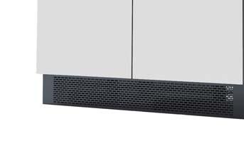
15 Description of main components (shown in Figure 2-3): 1. Roof Panel 2. Operation buttons and LCD display panel with protection cover 3. Emergency stop button 4. Door lock 5. AC circuit breaker 6. DC circuit breaker 11
16 Chapter 3 Installation Below is the installation instruction of the inverter. Please read carefully and install the product step-by-step. 1. CPS SC100KT-O/US-480 Check and make sure that the following items are included in the package before installation, as shown in Table 3-1. Table 3-1 Main items Item Q ty Note (1) CPS SC100KT-O/US Grid-tied PV inverter Grid-tied PV inverter (2) Accessory kit 1 Contains all necessary accessories The (2) Accessory kit contains items listed below: Table 3-2 Accessories Item Q ty Purpose User manual 1 Installation and operation 12
17 manual Warranty service card 1 For maintenance and repair Bottom baffle 2 For air convection Bottom filter 1 For dust proof M4 screw 8 For bottom baffles 3.1 Basic requirements NOTICE: Do not install the inverter under direct sunlight to avoid conversion efficiency de-rating caused by excessively high temperature. Check and make sure that the ambient temperature of the installation environment is -25 C ~+60 C; Make sure that the public power grid voltage is 422~528Vac and the grid frequency is 57.0~60.5Hz; Permission of grid connection has been granted by the local electric power authority; Installation personnel must be qualified electricians or people who have received professional training; 13
18 Sufficient convection space; Away from flammable and explosive substances; 3.2 Checklist of installation tools The checklist of tools for installation of the product: Table 3-3 No. Name Specification Function 1 Spline screwdriver T25 For screws on the backboard 2 Phillips head screwdriver PH2 For M3 and M4 screws 3 Open end wrench 0.55 inch For M8 screws 4 Open end wrench 0.67 inch For M10 screws 5 Straight screwdriver 0.12 inch For screws on dry contact 6 Sleeve 0.28 inch For M4 nuts 7 Torque wrench lb-in. For M10 screws 3.3 Mechanical installation (1) Dimensions Dimensions of CPS SC100KT-O/US-480 inverter are shown in Figure
19 72.83in in in. Figure 3-1 Sketch of dimensions There are 2 ways to install the foundation of inverter: (1) The dimensions of foundation installation for the first way are shown in Figure 3-2 (a). Please pay attention to the direction of the 4 fixing plates at the bottom. 15
20 3.94in. 4.13in in in. 4.33in in in. 1.97in. 2.64in. D=0.63in. Fixing plate 13.31in. Conduit area 1.97in. Figure 3-2 (a) Sketch of foundation installation dimensions Place the fixing plates inward, as shown in Figure 3-2 (b). Fixing plate Figure 3-2 (b) Inward direction to place fixing plates 16
21 3.94in. 4.13in in in. (2) The dimensions of foundation installation for the second way are shown in Figure 3-3 (a). Please pay attention to the direction of the 4 fixing plates at the bottom in. 1.10in in in. 2.64in. 1.97in. Conduit area D=0.63in. Fixing plate 13.31in. 1.97in. Figure 3-3 (a) Sketch of foundation installation dimensions Place the fixing plates outward (Figure 3-3 (b)). 17
22 Fixing plate Figure 3-3 (b) Outward direction to place fixing plates Requirements of inverter installation: According to the installation dimensions shown in Figure 3-2 (a) and 3-3 (a), secure the inverter on the hard ground or channel steel chassis with M12 foundation bolts through the 8 holes with a diameter of 0.63 inch at the bottom of the equipment. Front door: A 25.6-inch space should be reserved to ensure that the front door can be opened and closed freely. Back: A 31.5-inch space should be reserved for maintenance. The weight of the inverter is approximately pounds. Make sure that the mounting place can bear the weight. Two approaches are recommended to lift the machine, i.e. lifting with a crane or a forklift: 18
23 Lifting with a crane: Before lifting the machine, adjust the width of the forklift arm within 16.5~33.5 inches and insert the fork into the bottom of the machine from the back and lift it to the appropriate location for installation as shown in Figure 3-4. Figure 3-4 Diagram of lifting with a crane Lifting with a forklift: Adjust the width of the forklift arm within 16.5~33.5 inches and insert the fork into the bottom of the machine from the back and lift it to the appropriate 19
24 location for installation as shown in Figure 3-5. >16.54in. <33.46in. Figure 3-5 Diagram of lifting with a forklift 3.4 Electrical installation Open the front door of the machine. Proceed as shown in Figure Turn the handle bar of DC circuit breaker anti-clockwise to horizontal 20
25 position. 2 Turn the handle bar of AC circuit breaker anti-clockwise to horizontal position. 3 Unlock the door with the key. Pull the lock handle 45 degree outward to open the front door Figure 3-6 Diagram of opening front door 4 After opening the front door, remove the transparent Plexiglas cover for wiring. There are two ways to connect the external cables to the inverter: wiring from the bottom and wiring from the left side. (1) Wiring from the bottom: There are also 2 ways to connect cables from the bottom of the inverter. 1 Routing from rectangular conduit areas: 21
26 Remove the two bottom covers with a Phillips head screwdriver and connect cables to the inverter through the rectangular conduit areas, as shown in Figure 3-7. DC bottom cover AC bottom cover Figure 3-7 Routing from rectangular conduit areas 2 Routing from round holes on the two bottom covers: (a) Remove the cover screws, put the screws aside, and then take off the two covers; (b) Punch two holes on the DC bottom cover for DC conduits, as shown in Figure 3-8; (c) Punch three holes on the AC bottom cover one for the communication conduit, one for the AC conduit and one for 22
27 grounding conduit, as shown in Figure 3-9; For DC conduit Figure 3-8 Holes on DC bottom cover For communication conduit For AC conduit For grounding conduit Figure 3-9 Holes on AC bottom cover (d) Install steel connectors on the DC and AC bottom covers and check the seal of the cover; (e) Connect the steel conduits to these connectors; 23
28 (f) Restore the two covers to the inverter and attach the screws; (g) Put the cables through steel conduits to connect to the inverter, as shown in Figure Figure 3-10 Routing from round holes on the two bottom covers (2) Wiring from the left side: (a) Remove the screws on the left side cover with a Phillips head screwdriver, put the screws aside, and then take off the cover; (b) Punch five holes on the left bottom cover for steel conduits, as shown in Figure 3-11; 24
29 For communica tion conduit For DC conduit For AC conduit For Grounding conduit Figure 3-11 Holes on the left side cover (c) Install steel connectors on the left side cover and check the seal of the cover, as shown in Figure 3-12; Grounding DC AC Com. Figure 3-12 Installation of steel connectors 25
30 (d) Connect the steel conduits to these connectors; (e) Restore the cover to the inverter and attach the screws; (f) Put the cables through steel conduits to connect to the inverter, as shown in Figure 3-13; Figure 3-13 Wiring from the left side DC connection (1) To ensure the optimal performance of the inverter, please read the following guidelines before DC connection: (a) First, make sure that the maximum open circuit voltage of the PV modules is lower than 600Vdc under any conditions; (b) Ensure that the polarity of DC input is correct, i.e. the positive pole of PV module is connected to the positive pole of the inverter s DC 26
31 input, and the negative pole of PV module is connected to the negative pole of the inverter s DC input; (c) The Max. DC input current of the inverter is 350A, so 2AWG~ 3/0AWG copper cables with an insulation rating of 194 are recommended for inverter s DC input. The DC connection requirement is shown in Table 3-4: Table strings 3 strings 2 strings Positive 2AWG(35mm²) 1/0AWG (50 mm²) 3/0AWG (95 mm²) Negative 2AWG(35mm²) 1/0AWG (50 mm²) 3/0AWG (95 mm²) (d) Reserve a hole of 11mm diameter on the copper bar. Select the following recommended bolts to tighten the cables, see Table 3-5: Table 3-5 Type Length Torque Value Metric Bolt M10 25mm 24.6N-M (217.4Lb-In.) American Bolt 3/ N-M (217.4Lb-In.) INSTRUCTION: The standard DC configuration is 4 strings. Other configurations are 27
32 also available by changing corresponding fuses. The specification of fuses for DC input strings is shown in Table 3-6. Table 3-6 String # Fuse Rated Un(V) Fuse Rated In(A) Interrupting Rating Note kA Minimum set kA Minimum set kA Default set The position of DC fuses is shown in Figure Fuse Figure 3-14 Position of DC fuses 28
33 (2) Confirm that the input PV modules are of the same specifications and types before connection of DC input; (3) Connect the DC cables to the inverter s copper bar terminals on DC side according to the Table 3-7. In Table 3-6, CPS SC100KT-O/US-480, this type of inverter means that the negative pole of DC input needs to be connected to the Return ground bar and CPS SC100KT-OPG/US-480, this type of inverter means that the positive pole of DC input needs to be connected to the Return ground bar. Table 3-7 Type of Inverter Default way of grounding PV - PV+ CPS SC100KT-O/US-480 Negative grounding Return Hot CPS SC100KT-OPG/US-480 Positive grounding Hot Return NOTICE: Please choose the type of inverter based on the way of DC grounding system! Change of PV grounding in the inverter is prohibited without permission. Please contact our after-sale service personnel if the change of grounding in the inverter is necessary. 29
34 Return Hot PV PV+ Figure 3-15 DC connection of CPS SC100KT-O/US-480 Return Hot PV+ PV Figure 3-16 DC connection of CPS SC100KT-OPG/US
35 The two schematic diagrams of wire connection are shown in Figure Outside the inverter PV+ Hot Return Inside the inverter + = - ~ Outside the inverter PV- PV- PV+ Hot Return Inside the inverter + = - ~ GFDI Negative ground GFDI Positive ground (a) (b) Figure 3-17 Schematic diagram on DC side AC connection Connect the AC output of PV inverter to the AC cabinet or the power grid: (1) Use the recommended copper cables with an insulation rating of 194. The AC calbe requirement is shown in Table 3-8: Table 3-8 L1 L2 L3 Wire diameter 2/0AWG (70mm 2 ) 2/0AWG (70mm 2 ) 2/0AWG (70mm 2 ) Select the following recommended bolts to tighten the cables in Table 3-9: Table 3-9 Type Length Torque Value Metric Bolt M10 25mm 10N-M (88.5Lb-In.) 31
36 American Bolt 3/8 1 10N-M (88.5Lb-In.) (2) Connect the power grid A, B, C cables to the L1, L2, and L3 te rminals of the inverter, as shown in Figure 3-18: L1 L2 L3 Figure 3-18 AC output connection AC output cables (3) Make sure that all cables are well connected on the L1, L2, and L3 terminals Ground connection The ground copper bar is located at the bottom right corner of the inverter, as shown in Figure
37 Gnd copper bar Figure 3-19 Ground connection Connect the Ground (PE) cable to the Gnd terminal of Gnd copper bar. The Ground connection requirement is shown in Table Table 3-10 Item Gnd (PE) Wire diameter 2AWG (35mm 2 ) Nut Torque value M8 12.5N-M (113.5 Lb-In.) Communication connection RS485 communication connection: The signal pinboard on the inverter has 2 RS485 communication ports, which are RS485-1 and RS485-2 for field connections, as shown in Figure 33
38 RS485-1 RS Figure 3-20 Signal cable terminals for communication (1) The communication of one single local inverter is to connect the RS485 communication bus cable through the RS485-1 or RS485-2 port of the inverter directly. Shielded twisted pair (STP) cable should be used for RS485 communication with the maximum allowable length of 3280 feet. Wiring requirement of RS485-1/2 is shown in Table 3-10: Table 3-11 RS485-1/2 wiring requirement 34


39 No. Color Function 1 White orange Orange N.C. 3 White green Blue N.C. 5 White blue N.C. 6 Green N.C. 7 White brown N.C. 8 Brown N.C. The wires are labeled 1~8 from left to right, as shown in Figure 3-21: Figure 3-21 Diagram of RS485-1/2 wiring (2) For remote monitoring of more inverters, connect the RS485-2 port of one inverter to the RS485-1 port of another inverter and then connect to the 35
40 Dry contact 干接点 data logger through the RS485 communication bus cable. For more information about CPS monitoring solutions, please contact our after-sales service center Connection of dry contact The connection of dry contact is shown in Figure The two terminals are potential-free contacts for fault alarming of the inverter. The wiring requirement is shown in Table Figure 3-22 Diagram of Dry contact connection Table 3-12 Function Wire diameter Signal type Inverter fault alarm 18AWG (0.810mm 2 ) Dry contact (MAX 240VAC 2A) 36
41 3.4.6 Installation of bottom filter and baffles After all wire connections are completed, insert the filter into the filter slot at the bottom of the inverter. Then install the front and back baffles with the eight M4 screws (in the accessory pack), as shown in Figure Baffle Filter Baffle Figure 3-23 Diagram of bottom filter and baffles installation 37
42 Chapter 4 Initial On-grid Testing To ensure operational safety, initial on-grid testing is required as per the instructions in this chapter before connecting the inverter to PV panels and grid power after the installation of CPS SC100KT-O/US Testing steps Take the following steps for the initial on-grid test: (1) Check the appearance of inverter (2) Check AC connection (3) Check DC connection (4) Turn on AC circuit breaker (5) System self-check and time setup (6) Set up AC operational parameters (7) Set up DC operational parameters (8) Set up MPPT operational parameters (9) Turn on DC circuit breaker (10) Power train of self-check (11) Start up inverter 38
43 INSTRUCTION: Please refer to 5.3 Troubleshooting or contact our after-sale service personnel if any problem is found during the testing. 4.2 Testing procedure statement Check the appearance of inverter (1) Check whether the inverter has any visible abnormalities. Make sure that the DC and AC circuit breakers are turned off. Open the front door of the inverter and ensure the electrical components and connections are normal. (2) Check and make sure that all the cables are properly connected and free of defects. (3) Correct and record any identified problems Check AC connection (1) Check whether the power grid A, B, C, and PE cables are properly torqued on the appropriate L1, L2, L3 and Ground terminals. (2) Before connecting the inverter to the power grid, measure the line to line voltage between terminals of AC cables. The voltage of L1-L2, L2-L3 and L3-L1 should be within the range of Vac. (3) If abnormal power grid voltage or no voltage is detected, please 39
44 reconfirm the power transmission from the power grid to the inverter. If there is nothing wrong with the power transmission, check whether the AC connection is correct. (4) Correct and record any identified problems Check DC connection (1) Check whether the PV cables are properly torqued on the appropriate DC terminals. (2) Put through the DC input from PV panels, combiner boxes or other DC distribution equipments and then measure the voltage between Hot and Return bars. INSTRUCTION: If no voltage is detected, check whether the connection from DC source to the inverter is correct. Maybe the combiner boxes are not properly connected or there is a short circuit in the DC cables. (3) Confirm whether the polarity of DC connection is correct. NOTICE: If the polarity of the DC cables is not correct, the inverter will be 40
45 damaged. (4) Correct and record any identified problems Turn on AC circuit breaker (1) Close the front door of the inverter. (2) Turn on the AC circuit breaker. The auxiliary power supply of the inverter will be energized and the control circuit be activated. (3) Check carefully whether there is any abnormality. (4) Turn off the AC circuit breaker immediately if there is any abnormality. Reconfirm whether the previous testing steps are correct. Stop testing if anything abnormal occurs System self-check and time set-up (1) Sys. Checking will be indicated on the LCD when the AC circuit breaker is turned on. (2) The inverter will stand by after the self-check of system (about 30 seconds) is completed. Meanwhile, fault indication interface will be shown on the LCD if any malfunction occurs. The specific fault indication and solution are available to be found in 5.3 Troubleshooting. Besides, since the DC circuit breaker is not turned on, the fault 41
46 Warn0040 will be indicated on the LCD. Please ignore the fault and keep the DC circuit breaker in OFF state. (Please don t turn on the DC circuit breaker until it is allowed in the Chapter 4.2.9). (3) Enter the 4 SysTime menu and set up the present date and time according to System setup Set up AC operational parameters Enter 1 SysPara menu according to System protection parameter setup. (1) Check the AC voltage, frequency protection value and time of protection actions. (2) Change the parameters referring to the Protection Parameters Table in Chapter if necessary. (3) Record the changed parameters Set up DC operational parameters (1) Check the PV startup voltage and startup time of the inverter. (2) Change the parameters if necessary. (3) Record the changed parameters. 42
47 4.2.8 Set up MPPT operational parameters (1) Check the active derating and reactive compensation parameters of the inverter; (2) Set the active power derating to 10%. (3) Record the changed parameters Turn on DC circuit breaker (1) Turn off the AC circuit breaker. (2) Turn on the DC circuit breaker to provide the PV power supply to the DC side of the inverter. (3) Check carefully whether there is abnormality. (4) Turn off the DC circuit breaker if there is any abnormality. Reconfirm whether the previous testing steps are correct. Stop testing if anything abnormal occurs Power train of self-check (1) Confirm that the front door of the inverter is closed and locked. (2) Turn on the AC circuit breaker. (3) Wait for the inverter to stand by, the status of which will be indicated on the LCD. 43
48 (4) Select 2 PowerTrain on the LCD and press ENT according to System setup. Then self-check interface will be indicated on the LCD. (Figure 4-1) After pressing ENT, the system begins self-checking. (Figure 4-2) PowerTrain? Figure 4-1 Self-check confirmation interface PowerTrain.. Figure 4-2 System self-checking (4) If Low PV Volt is indicated on the LCD, as shown in Figure 4-3, check whether the DC connection is correct and whether the DC voltage is below 300V (subject to grid voltage). 44
49 Low PV Volt Figure 4-3 Low Volt (5) If PowerTrainFualt is indicated on the LCD, as shown in Figure 4-4, check whether the DC circuit breaker is turned on. Then check whether the inverter is in ON State according to System setup. If the fault still occurs when the DC circuit breaker is turned on and the inverter is ON State, turn off the AC and DC circuit breakers immediately and then contact our after-sales service personnel. PowerTrainFault Figure 4-4 Self-check fails (6) If the self-check is successful, PowerTrain OK will be indicated on the LCD, as shown in Figure 4-5. Press ESC to return to the main menu. 45
50 PowerTrain OK Figure 4-5 Self-check OK Start up inverter (1) If the PV voltage reaches the startup voltage (subject to the grid voltage and 330V is the default minimum voltage.) and the grid voltage meets the requirement of grid connection, the inverter will be energized to start up after 7-15 minutes under stand-by mode. The largest output power is 10% of the rated power. (The active power derating was set to 10%.) (2)If nothing abnormal happens, the active derating value can be gradually increased to 100%. (3)Check all the operation information on the LCD. (4)Turn off the AC and DC circuit breaker or press the emergency stop button if anything abnormal occurs. 46
51 Chapter 5 Operation NOTICE: To ensure operational safety, run the initial on-grid testing before operating on the inverter. 5.1 Shut-down and Start-up Shut-down Manual shut-down : Normally, manual shutdown is not necessary. But the inverter can be shut down manually for maintenance or user s needs. (1) Move the cursor from the main operation interface to 4 Setting according to System setup. Press ENTER and go to submenu 1 ON/OFF. The inverter will be shut down and enter OFF State after moving the cursor to OFF and press ENTER. (2) Press the emergency stop button on the panel to shut down the inverter in case of emergencies. Then the fault alert EmergencyStp will be indicated on the LCD and the inverter will stop working. Once the emergency stop button is restored, the fault alert will be eliminated and the inverter will restart working automatically. Automatic shut-down: The inverter will be shut down automatically and 47
52 enter standby mode when the output voltage of PV panel is lower than the set point (300Vdc minimum), or AC power grid fails; or the ambient temperature exceeds the normal range. The inverter will restart working automatically when the appropriate grid-connection condition is detected. Manual Shut-down for maintenance: If service personnel need to maintain or repair the inverter, please follow the following steps. (1) Shut down the inverter according to the manual shut-down steps. Turn off the DC circuit breaker and ensure that the AC circuit breaker is turned on. (2) Referring to System setup, move the cursor from the main operation interface to 4 Setting, press ENTER and go to submenu 6 OtherCmd. Then move the cursor to 1 De-energy and press ENTER, as shown in Figure 5-1. After pressing ENTER to confirm, the DC bus capacitor begins to discharge, as shown in Figure 5-2. De-energy? Figure 5-1 Inverter de-energy interface 48
53 De-energy.. Figure 5-2 De-energy ongoing (3) When De-energy is successfully completed (Figure 5-3), press ESC to return to the main menu. Check the PV voltage on the LCD according to Operation information or check the voltage of DC bus capacitor with a voltmeter. Don t turn off the AC circuit breaker or perform maintenance to the inverter until the DC bus capacitor is discharged to safe voltage, as shown in Figure 5-3. De-energy OK Figure 5-3 De-energy OK interface (4) If De-energy fails, as shown on the LCD in Figure 5-4. It takes at least 60 minutes for the inverter to discharge automatically by turning off the AC circuit breaker. The inverter should not be maintained until the voltmeter 49
54 shows that there is no electric charge left in the DC bus capacitor. InverterErr Figure 5-4 De-energy error interface (5) If the DC circuit breaker is not turned off, LCD will remind the user to TurnOff DC Break, as shown in Figure 5-5. Please turn off the DC circuit breaker and press ENT to continue discharging. TurnOff DC Break Start-up Figure 5-5 Turnoff DC circuit breaker Turn on the DC and AC circuit breakers. Manual start-up: Manual start-up is required after a manual shut-down or a fault shut-down by the user. Move the cursor from the main operation interface to 4 Setting according 50
55 to System setup. Press ENTER and go to submenu 1 ON/OFF. Then move the cursor to ON and press ENTER to start the inverter. Then the inverter will start up and operate normally if the start-up condition is met. Otherwise, the inverter stands by. Automatic start-up: Confirm that the inverter is ON State at first. The inverter will start up automatically when the output voltage (Default value is 330V, which can be adjusted according to System setup.) of PV panel meets the set point, AC power grid is normal, and the ambient temperature is within allowable operating range. 5.2 Operation mode There are 4 operation modes. The following are corresponding indications for each mode. (1) System check mode is shown in Figure 5-6: System is in self check status when inverter is energized. The program will complete initialization during this process. 51
56 Sys.Checking >>>>>> Figure 5-6 System self check ongoing (2) Standby mode, as shown in Figure 5-7: After self check is completed, the inverter will turn into standby mode if the output voltage of PV panel, AC power grid or ambient temperature does not meet the startup conditions. But the inverter will continue to check whether the startup conditions are met in standby mode until it comes back to normal operation mode. If the warning SPICommErr occurs and the FAULT LED is blinking, the operation mode shown by LCD may not be correct even if LCD shows Standby. Please refer to the solution of SPICommErr in 5-1 Troubleshooting Table on Page 49. Standby >>>>>> Figure 5-7 Inverter system in standby (3) Normal operation mode, as shown in Figure 5-8: 52

57 The inverter will turn from standby into normal operation mode when the startup conditions are met as long as the inverter is ON State. In this mode, the inverter converts DC generated by PV modules to AC and feeds the AC to the power grid. Under the normal operation mode, the inverter will maximize the DC output from PV panels in the manner of MPPT (Maximum Power Point Tracking). Meanwhile, the inverter will check the power grid and PV output voltage constantly. Once anything abnormal occurs, the inverter will stop working and take self-protection. Figure 5-8 Normal operation mode interface (4) Fault mode, as shown in Figure 5-9: The inverter will stop working, disconnect from the power grid and turn into fault mode when the inverter or power grid fails. Check the fault information on the LCD according to Present fault and History. To find the specific cause and solution, you can refer to Table 5-1 in 5.3 Troubleshooting. 53
58 GridV.OutLim Figure 5-9 Fault indication interface 5.3 Troubleshooting Before you contact our after-sales service center, you are able to find most faults and solutions in Table 5-1 for the troubleshooting. There are three kinds of fault alert statuses: Warn, Protect and Fault. When there is a Warn, the system only reminds customers of the problem while it doesn t change the operation mode. When there is a Protect, the system will turn into fault mode and come back to normal when the Protect disappears. When there is a Fault, the system will stop working and remain standby until resetting the system or repair the inverter to eliminate the fault. Two ways of system reset are listed as follows: 1. Turn off the AC circuit breaker, wait for 5 seconds and turn on the AC circuit breaker again to recharge the system control unit. If the system check is passed, the inverter will turn into normal operation mode. 2. Run the 2 Restart command to reboot the system according to
59 System protection parameter setup. The causes of fault can be identified based on the faults listed in Table 5-1. Please contact our after-sales service if the fault still exists. WARNING: Shut down the inverter before maintaining the inverter. Disconnect the inverter from PV panels and the Power Grid and make sure there is no electric charge left in the inverter before the maintenance. 55
60 Table 5-1 Troubleshooting Table Definition: Communication inside inverter fails Possible causes: 1. Communication circuits inside inverter are loose; 2. LCD software problem; 1. SPICommErr 3. Inverter software problem; Warn Recommended solutions: 1. Observe for 5 minutes and see whether the alarm will be eliminated automatically; 2. Turn off 3-phase working power supply and then reboot the system; 3. Contact our after-sales service center. Definition: 2. Warn0010 Fan (invisible from outside) inside inverter is working abnormally 56
61 Possible causes: 1. Fan is blocked; 2. Power supply circuit of the fan has problem; 3. Fan state test circuit is loose; 4. Fan service life has expired; 5. Inverter software problem Recommended solutions: 1. Observe for 5 minutes and see whether the alarm will be eliminated automatically; 2. Switch off 3-phase working power supply and then reboot the system; 3. Contact our after-sales service center. Definition: Eeprom error 3. Warn0030 Possible causes: Internal storage error Recommended solutions: 1. Observe for 5 minutes and see whether the 57
62 alarm will be eliminated automatically; 2. Contact our after-sales service center Definition: DC circuit breaker error Possible causes: 1. PV positive pole and negative pole are connected reversely; 2. PV over-current; 3. DC breaker is damaged; 4. Warn DC circuit breaker is turned off Recommended solutions: 1. Observe for 5 minutes and see whether the alarm will be eliminated automatically; 2. Check DC breaker; 3. Check PV cable connection; 4. Check whether the sunlight is too strong or the configuration of PV panel is appropriate; 5. Contact our after-sales service center 5. Warn0050 Definition: 58
63 Temperature sensor error Possible causes: 1. Temperature inside inverter exceeds normal range; 2. Temperature sensor has problem Recommended solutions: 1. Observe for 5 minutes and see whether the alarm will be eliminated automatically; 2. Check whether the operation temperature is -25 ~60 ; 3. Contact our after-sales service center Definition: Inside warning 6. Warn0010~0150 Possible causes: Inverter has inside problem Recommended solutions: 1. Observe for 5 minutes and see whether the alarm will be eliminated automatically; 59
64 2. Contact our after-sales service center Definition: Ambient temperature or temperature inside inverter is too high Possible causes: 1. Ambient temperature outside the inverter is too high; 2. Radiation air inlet is blocked; Too much dust is on the filter net; Protect 1. TempOver 3. Radiation fan is blocked without rotation Recommended solutions: 1. Confirm that external ambient temperature is within the specified range of operating temperature; 2. Check whether radiation air inlet is blocked and filter net has too much dust; 3. Whether radiation fan is blocked; 4. Observe for 30 minutes and see whether the alarm will be eliminated automatically; 60
65 5. Contact our after-sales service center Definition: Grid voltage exceeds the allowable range, or power grid is not detected Possible causes: 1. Grid voltage is abnormal; 2. Power grid breaks down; 3. Cable connection between the inverter and the grid is disconnected; 2. GridV.OutLim 4. Inverter has an internal fault Recommended solutions: 1. Observe for 10 minutes and see whether the alarm will be eliminated automatically; 2. Check whether the grid voltage is within the allowable range; 3. Check whether the cable connection to the grid is disconnected or abnormal; 4. Contact our after-sales service center 3. GridF.OutLim Definition: 61
66 Grid voltage frequency is abnormal, or grid is not detected Possible causes: 1. Grid frequency is abnormal; 2. Power grid breaks down; 3. Cable connection between the inverter and the grid is disconnected; 4. Inverter has an internal fault Recommended solutions: 1. Observe for 10 minutes and see whether the alarm will be eliminated automatically; 2. Check whether the grid frequency is within the allowable range; 3. Check whether the cable connection to the grid is disconnected or abnormal; 4. Contact our after-sales service center Definition: 4. PV.VoltOver PV voltage exceeds the allowable value Possible causes: 62
67 1. PV over-voltage 2. Inverter has an internal fault Recommended solutions: 1. Observe for 30 minutes and see whether the alarm will be eliminated automatically; 2. Check whether PV voltage exceeds the allowable range; 3. Disconnect from PV input, wait for 5 minutes and reconnect to PV input; 4. Contact our after-sales service center Definition: PV panel is connected reversely Possible causes: 1. PV positive pole and negative pole are 5. PV.Reverse connected reversely; 2. Inverter has an internal fault Recommended solutions: 1. Check whether positive pole and negative pole are connected reversely; 63
68 2. Contact our after-sales service center Definition: AC contactor is abnormal Possible causes: 6. AC.ContErr 1. AC contactor is damaged; 2. Inverter has an internal fault Recommended solutions: Contact our after-sales service center Definition: Inverter is in the status of emergent stop Possible causes: 1. Emergency stop button is pressed 7. EmergencyStp 2. Inverter has an internal fault Recommended solutions: 1. Check whether emergency stop button is pressed. If so, restore the button; 2. Contact our after-sales service center if the problem still exists 64
69 Definition: Grounding fault Possible causes: 1. Ground connection inside inverter is abnormal 8. GFDIErr 2. Inverter has an internal fault Recommended solutions: 1. Check whether the system has ground connection or grounding fault; 2. Check whether the LED on GFDI is lighted on. If so, replace with a new fuse; 3. Contact our after-sales service center Definition: Internal protection of inverter 9. Protect0010~0620 Possible causes: Internal protection of inverter Recommended solutions: 1. Observe for 10 minutes and see whether the 65
70 alarm will be eliminated automatically; 2. Contact our after-sales service center Definition: Fault inside inverter Possible causes: Serious fault occurs inside inverter Fault Fault0010~0160 Recommended solutions: 1. The inverter can be restarted referring to System protection parameters setup if it is confirmed that there is no other problem; 2. Contact our after-sales service center 66
71 Chapter 6 Human Machine Interface 6.1 Description of LCD panel The CPS SC100KT-O/US-480 LCD panel is protected with a cover which can be opened by switching the cover lock to the right, as shown in Figure 6-1. Figure 6-1 Switch the cover lock 67
72 The LCD panel consists of LCD screen, LED lights, buzzer and 6 keys, as shown in Figure 6-2. Figure 6-2 LCD panel Different LED statuses are described in Table 6-1 and key functions are listed in Table 6-2. Table 6-1 LED Indication LED Sign Description State Status POWER Work power supply indicator light Light up Energized (control panel starts to work) 68
73 Light off No working power supply Light up In grid connection and power generation state RUN Grid connection operation indicator light Blink Derated running state (light up 0.5s, light off 1.6s) Light off In other operation state or no working power supply Light up Grid is normal GRID Grid state indicator light Blink Grid abnormal (light up 0.5s, light off 1.6s) Light off No working power supply Light up Fault occurs Slow Alarm occurs (light up 0.5s, FAULT Fault state indicator light blink Quick blink light off 2s) Protective action (light up 0.5s, light off 0.5s) Light off No fault or no working power supply 69
74 Table 6-2 Definitions of the keys Key Description Definition of function Escape Back/end/mute Enter Confirm entering the menu /Confirm set point Up Page up in selection menu Down Page down in selection menu Left -1 when setting parameters Right +1 when setting parameters 6.2 Operation state Table 6-1 indicates the definitions of LED, i.e. indicates the information of the inverter s operation state. It indicates that the system is energized and under DSP control when POWER lights up. RUN will light up when the inverter detects that the grid connection conditions meet the requirements and power is fed to the grid. RUN will blink 70
75 if the grid is in derated running state during the period of feeding power to the grid. GRID will light up when the grid is normal during the operation of the inverter. Otherwise, GRID will blink until the grid restores to normal. FAULT will blink quickly as a fault (except grid abnormality) occurs. FAULT will not light off until the fault is eliminated. The light will blink slowly when an alarm occurs. FAULT keeps lighting up when an internal fault occurs. FAULT will not light up if both the inverter and grid are normal. The buzzer will give alarms if a fault (power grid abnormality included) occurs. 6.3 Interface and menu functions Users can perform the corresponding operations with the 6 function keys according to the indications of the LCD Interface types (1) The LCD interface starts with the company logo once the system is energized, as shown in Figure
76 Figure 6-3 LOGO interface (2) Indication of inverter operation mode: Sys.Checking >>>>>> Figure 6-4 Inverter system check ongoing Standby >>>>>> Figure 6-5 Inverter system in standby mode 72
77 PV = 479 VAC 420 V 19.8 kw 48.7 A ~ 78.5 kwh 06/07 12:09:01 Figure 6-6 Default display interface for normal operation GridV.OutLim Figure 6-7 Fault indication interface LCD screen will display different mode interfaces based on the operation modes of the inverter. There are four operation modes: startup system check mode (as shown in Figure 6-4), stand-by mode (as shown in Figure 6-5), normal operation mode (as shown in Figure 6-6) and fault mode (as shown in Figure 6-7). The default indication interface mainly indicates PV voltage, PV current, Grid voltage, instant power, daily generated power and time information under normal operation. The present fault information will be indicated on the LCD screen when 73
78 the inverter is in fault mode Main operation interface LCD screen displays default indication interface when the inverter is in operation mode. Press the ESC key in this interface to escape the default interface and enter the main operation interface. The main operation interface is shown in Figure OP.Info 2 Alarm 3 History 4 Setting 5 Dispatch Figure 6-8 Contents indicated on the main operation interface The main operation interface of LCD screen has 5 menus, i.e. 1 OP. Info, 2 Alarm, 3 History, 4 Setting and 5 Dispatch. The users may select options with PAGEUP and PAGEDOWN, and then press ENTER to confirm selection. The users can return to the default indication interface by pressing the ESC key. 74
79 6.3.3 Operation information When the cursor moves to 1 OP. Info in the main interface, press ENTER to select the operation information as shown in Figure 6-9. Check the information by pressing PAGEUP and PAGEDOWN. Return to the previous menu and enter the main operation interface by pressing ESC. 1 OP.Info Yield MPac Pac RunT 23.5kWh 20.0kW 19.8kW 12.1 h Uab 480.0V Ubc 478.9V Uca 479.5V Freq 60.0Hz Ia 22.7A Ib 22.7A Ic 22.7A Tmod 78.2C Tamb 50 C Upv 420.0V Ipv 48.7A Figure 6-9 Operation information indication 75
80 6.3.4 Present fault As described before, when faults occur during the normal operation of the inverter, corresponding fault message will be indicated in 2 Alarm menu besides the sound and light alarms. Move the cursor to 2 Alarm and press ENTER to check out the specific fault information, as shown in Figure If not existed 2 Alarm No Alarm existed SPICommErr IntProtectA Figure 6-10 Present fault information History Move the cursor to 3 History in the main interface. Press ENTER to check the history information, as shown in Figure There are 4 submenus in 3 History : 1 HistErr, 2 OP. Recd, 3 Version and 4 TotalTag. (1) UP to 100 pieces of latest fault messages can be recorded and found in 1 HistErr menu. (2) The latest 21 days operation history data is available to be found in 2 OP. Recd menu. All variable names in the data comply with the content in 1 76
81 OP. Info menu of the main interface. The users can select the 2 OP. Recd menu and input the retraceable days (For example, the input number is 21. If the current date is December 15th, the LCD will indicate the operation information of 21 days before that date which is November 24th). (3) Software version, hardware version and serial number of the product are listed in 3 Version menu. (4) Cumulative generated power since the first day the inverter began working is available to be found in 4 TotalTag menu. If not existed NoError Existed 1.St :50 SPICommErr 2.Ed :59 SPICommErr 3 History 1 HistErr 2 OP.Recd 3 Version 4 TotalTag Pls input date 2 ß 12/15 RunT MPac Yield 6.3 h 20.0KW 123.5KWh MachVer 1.00 SerialNo T- Yield (kwh) Figure 6-11 History menu and submenu 77
82 6.3.6 System setup Move the cursor to 4 Setting in the main interface. Press ENTER to set the current system parameters, as shown in Figure There are 6 submenus in 4 Setting : 1 ON/OFF, 2 Language, 3 Buzzer, 4 SysTime, 5 Commun and 6 OtherCmd. (1) The inverter can be started and shut down with 1 ON/OFF menu. Move the cursor to ON and press ENTER, ON State will then be indicated at the bottom of LCD screen ; move the cursor to OFF and press ENTER, then OFF State will be indicated as well. The inverter will stand by instead of working normally if the startup conditions are not satisfied even ON is selected. The inverter will be shut down immediately if OFF is selected in any cases. (2) Two languages, i.e. English and Chinese are available in 2 Language menu. (3) Key beep and fault beep can be set mute/unmute in 3 Buzzer menu. Key beep and Alarm beep can be shifted by pressing PAGEUP and PAGEDOWN. Shift between Enable and Disable by pressing LEFT and Right if the cursor is on the Key beep. Complete the setup by pressing ENTER. Similarly, the fault beep can be set up as well. 78
CPS Energy Balancer. Version: 1.0
 CPS Energy Balancer Version: 1.0 CHINT POWER SYSTEMS AMERICA CO., LTD. Address: 700 International Parkway, Suite 102 Richardson, Texas Zip Code: 75081 Web: www.chintpower.com/na Email: americasales@chintpower.com
CPS SCA Series Grid-Tied PV-Inverter CPS SCA3/4/5KTL-O/US. Installation and Operation Manual
 CPS SCA Series Grid-Tied PV-Inverter CPS SCA3/4/5KTL-O/US Installation and Operation Manual Version 1.0 Table of Contents Before You Start...1 Chapter 1 IMPORTANT Safety Instructions...2 Chapter 2 Overview...5
User Manual. Solar Charge Controller 3KW
 User Manual Solar Charge Controller 3KW 1 CONTENTS 1 ABOUT THIS MANUAL... 3 1.1 Purpose... 3 1.2 Scope... 3 1.3 SAFETY INSTRUCTIONS... 3 2 INTRODUCTION... 4 2.1 Features... 4 2.2 Product Overview... 5
User Manual Solar Charge Controller 3KW
 User Manual Solar Charge Controller 3KW Version: 1.3 CONTENTS 1 ABOUT THIS MANUAL... 1 1.1 Purpose... 1 1.2 Scope... 1 1.3 SAFETY INSTRUCTIONS... 1 2 INTRODUCTION... 2 2.1 Features... 2 2.2 Product Overview...
Manual. BlueSolar Grid Inverter 1500 / / / / / 230
 Manual EN BlueSolar Grid Inverter 1500 / 230 2000 / 230 2800 / 230 4000 / 230 5000 / 230 Before you start This manual contains important information regarding installation and safe operation of this unit.
User Manual 1KVA/ 2KVA/ 3KVA INVERTER / CHARGER
 User Manual 1KVA/ 2KVA/ 3KVA INVERTER / CHARGER CONTENTS ABOUT THIS MANUAL... 1 Purpose... 1 Scope... 1 SAFETY INSTRUCTIONS... 1 INTRODUCTION... 2 Features... 2 Basic System Architecture... 2 Product Overview...
On Line UPS. LUC 1000E / LUC 2000E / LUC 3000E User Manual
 On Line UPS LUC 1000E / LUC 2000E / LUC 3000E User Manual Save This Manual Please read this manual carefully prior to storage, installation, wiring, operation and maintenance of the UPS. This manual contains
8 Troubleshooting and Maintenance
 8 Troubleshooting and Maintenance 8.1 Troubleshooting 8.1.1 Troubleshooting of LED Indicators See Tab. 7-4 State Descriptions of LED Indicators for the definition. Fault Type LED indicators and LCD screen
USER'S GUIDE. WiseHP11 SINGLE PHASE HIGH PRECISION AVR SERVO-MOTOR AUTOMATIC VOLTAGE STABILIZER
 USER'S GUIDE WiseHP11 SINGLE PHASE HIGH PRECISION AVR SERVO-MOTOR AUTOMATIC VOLTAGE STABILIZER LEN.MAN.STA.145 Rev.5.00/2010 CONTENTS 1. SAFETY INSTRUCTIONS 1 2. INTRODUCTION 2 3. FRONT PANEL AND INSIDE
User Manual 1KVA-5KVA INVERTER / CHARGER
 User Manual 1KVA-5KVA INVERTER / CHARGER Version: 1.7 Table Of Contents ABOUT THIS MANUAL... 1 Purpose... 1 Scope... 1 SAFETY INSTRUCTIONS... 1 INTRODUCTION... 2 Features... 2 Basic System Architecture...
User manual. Solar Hybrid 1-5KVA. Uninterruptible Power Supply / Charger
 User manual Solar Hybrid 1-5KVA Uninterruptible Power Supply / Charger All rights reserved. The information in this document is subject to change without notice. Thank you for purchasing this series UPS.
USER MANUAL. IPS home inverters with UPS function. IPS home inverter manual
 USER MANUAL IPS home inverters with UPS function Suitable for UPS: - IPS300-SIN - IPS300-SIN-WM - IPS300-SIN-DC - IPS600-SIN - IPS600-SIN-WM - IPS600-SIN-DC - IPS1000-SIN - IPS1000-SIN-DC - IPS1600-SIN
User Manual 5KVA/5KW INVERTER / CHARGER. Version: 1.3
 User Manual 5KVA/5KW INVERTER / CHARGER Version: 1.3 Table Of Contents ABOUT THIS MANUAL... 1 Purpose... 1 Scope... 1 SAFETY INSTRUCTIONS... 1 INTRODUCTION... 2 Features... 2 Basic System Architecture...
STONESTAR AUSTRALIA PTY LTD
 42 48 REDWOOD DRIVER,DINGLEY VIC3172,AUSTRALIA TEL:0061 3 95518393 FAX:0061 3 95580776 EMAIL:stonestar@ssawheels.com.au Contents 1. Product Introduction... 3 2. Installation... 5 1) Safety instructions...
CP-250E-60/72-208/240-MC4 Microinverter with Modular Trunk Cable
 CP-250E-60/72-208/240-MC4 Microinverter with Modular Trunk Cable Chilicon Power Aug 2016 1 CONTENTS CP-250E Microinverter System... 3 The CP-100 Cortex Gateway... 3 Important Safety Information... 4 Inverter
User Manual 1.5KVA-3KVA INVERTER / CHARGER. Version: 1.1
 User Manual 1.5KVA-3KVA INVERTER / CHARGER Version: 1.1 Table Of Contents ABOUT THIS MANUAL... 1 Purpose... 1 Scope... 1 SAFETY INSTRUCTIONS... 1 INTRODUCTION... 2 Features... 2 Basic System Architecture...
User Manual 4KVA/ 5KVA INVERTER / CHARGER. With MPPT Controller
 User Manual 4KVA/ 5KVA INVERTER / CHARGER With MPPT Controller CONTENTS ABOUT THIS MANUAL... 1 Purpose... 1 Scope... 1 SAFETY INSTRUCTIONS... 1 INTRODUCTION... 2 Features... 2 Basic System Architecture...
Solar Hybrid Inverter SP Brilliant Series
 User Manual Solar Hybrid Inverter SP Brilliant Series Version: 1.5 Table Of Contents ABOUT THIS MANUAL... 1 Purpose... 1 Scope... 1 SAFETY INSTRUCTIONS... 1 INTRODUCTION... 2 Features... 2 Basic System
NB NB 1511 NB NB 4031 TRUE ON-LINE DOUBLE CONVERSION UPS
 NB 0811 - NB 1511 NB 0831 - NB 4031 TRUE ON-LINE DOUBLE CONVERSION UPS LEN.MAN.UPS.069 Rev.2.00/2002 CONTENTS Safety Instructions 1 Introduction 3 2.1 FEATURE 3 2.2 UPS modules 4 How the UPS works 5 3.1
Installation Guide Smart-UPS On-Line SRT1000/1500 UXI-NCLI, SRT1000/1500 UXI-LI, Tower/Rack-Mount
 Installation Guide Smart-UPS On-Line SRT1000/1500 UXI-NCLI, SRT1000/1500 UXI-LI, Tower/Rack-Mount Important Safety Messages Read the instructions carefully to become familiar with the equipment before
Commercial 1000VDC String Inverter XGI Installation and Operation Guide Models: XGI XGI
 Commercial 1000VDC String Inverter XGI 1000 Installation and Operation Guide Models: XGI 1000-60 XGI 1000-65 1. Important Safety Instructions... 4 1.1. Hazard Symbols... 4 1.2. Symbols on Labels... 4 1.3.
3KW Off-grid Solar Power System LFP Battery
 3KW Off-grid Solar Power System LFP Battery 1 CATALOGUE 1. S u m m a r y 3 2. T e c h n i c a l p a r a m e t e r 4 3. D i s p l a y a n d f u n c t i o n i n s t r u c t i o n 5 4. S e q u e n c e o f
MPPT Controller PVTS Series User Manual. User Manual. 800W-4000W Hybrid solar inverter. Version: 1.4
 User Manual 800W-4000W Hybrid solar inverter Version: 1.4 Table Of Contents ABOUT THIS MANUAL... 1 Purpose... 1 Scope... 1 SAFETY INSTRUCTIONS... 1 INTRODUCTION... 2 Features... 2 Basic System Architecture...
User Manual 1.5KVA-3KVA INVERTER / CHARGER
 User Manual 1.5KVA-3KVA INVERTER / CHARGER Version: 1.0 Table Of Contents ABOUT THIS MANUAL... 1 Purpose... 1 Scope... 1 SAFETY INSTRUCTIONS... 1 INTRODUCTION... 2 Features... 2 Basic System Architecture...
FLÄKTGROUP PM-MOTOR WITH INTEGRATED FC 106 FREQUENCY CONVERTER
 FLÄKTGROUP PM-MOTOR WITH INTEGRATED FC 106 FREQUENCY CONVERTER INSTALLATION AND MAINTENANCE INSTRUCTIONS Risk of electric shock: Motor terminals may still be live if the impeller is rotating, even when
User Manual. 3kW Hybrid PV Inverter HX-3000
 User Manual 3kW Hybrid PV Inverter HX-3000 Table Of Contents 1. Introduction...1 2. Important Safety Warning...2 3. Unpacking & Overview...4 3-1. Packing List... 4 3-2. Product Overview... 4 4. Installation...5
User Manual 1KVA-5KVA (PF1) INVERTER / CHARGER. Version: 1.0
 INVERTER / CHARGER. Version: 1.0") User Manual 1KVA-5KVA (PF1) INVERTER / CHARGER Version: 1.0 Table Of Contents ABOUT THIS MANUAL... 1 Purpose... 1 Scope... 1 SAFETY INSTRUCTIONS... 1 INTRODUCTION... 2 Features... 2 Basic System Architecture...
User Manual 1KVA-5KVA (PF1) INVERTER / CHARGER Version: 1.0 Table Of Contents ABOUT THIS MANUAL... 1 Purpose... 1 Scope... 1 SAFETY INSTRUCTIONS... 1 INTRODUCTION... 2 Features... 2 Basic System Architecture...
User Manual SOLARMAX 1KVA/ 2KVA/ 3KVA INVERTER / CHARGER
 User Manual SOLARMAX 1KVA/ 2KVA/ 3KVA INVERTER / CHARGER WWW.POWERHIGHWAY.NET CONTENTS ABOUT THIS MANUAL... 1 Purpose... 1 Scope... 1 SAFETY INSTRUCTIONS...... 1 INTRODUCTION... 2 Features... 2 Basic System
PVES Series User Manual User Manual Shenzhen Pvinergy Technologies Co., Ltd
 User Manual Shenzhen Pvinergy Technologies Co., Ltd PVES Series Solar Residential System Overview Thank you for choosing PVES series solar residential system from Shenzhen Pvinergy Technologies Co., Ltd.
Battery & Energy Meter Quick Guide
 Battery & Energy Meter Quick Guide Issue: 01 Date: 2017-12-07 1 Preparing Cables Copyright Huawei Technologies Co., Ltd. 2017. All rights reserved. The battery output voltage should always be lower than
1KVA/ 2KVA/ 3KVA/ 4KVA/ 5KVA MS, LV MPPT INVERTER / CHARGER. User Manual. Version: 2.3
 1KVA/ 2KVA/ 3KVA/ 4KVA/ 5KVA MS, LV MPPT INVERTER / CHARGER User Manual Version: 2.3 Table Of Contents ABOUT THIS MANUAL... 1 Purpose... 1 Scope... 1 SAFETY INSTRUCTIONS... 1 INTRODUCTION... 2 Features...
Power Inverter. User s Manual. Diamond Series CPD1200EILCD
 Power Inverter Diamond Series CPD1200EILCD User s Manual 2 TABLE OF CONTENTS 1 IMPORTANT SAFETY INSTRUCTIONS..4 2 INSTALLATION....5 2-1 Unpacking...5 2-2 Product Overview & Outlook..5 2-3 Power Requirements
USER S MANUAL CONTENTS. Uninterruptible Power Supply 1. INTRODUCTION SAFTY INSTRUCTION CABLE CONNECTION... 4
 USER S MANUAL ON-LINE 1K/2K/3KVA CONTENTS 1. INTRODUCTION...... 1 2. SAFTY INSTRUCTION.......... 2 3. CABLE CONNECTION.......... 4 4. SYSTEM DESCRIPTION............ 5 5. UPS OPERATION...... 12 6. TROUBLE
SOLAR INVERTER/CHARGER 1000VA/1500VA/2000VA. Appliances. PC TV Light Electricfan
 SOLAR INVERTER/CHARGER SOLAR INVERTER/CHARGER 1000VA/1500VA/2000VA Appliances 420-00300-02 PC TV Light Electricfan Table Of Contents GENERAL PRECAUTIONS... 1 PERSONNEL PRECAUTIONS... 1 INTRODUCTION...
SineWave Guardian TM 380V 600V INSTALLATION GUIDE. Quick Reference. ❶ How to Install Pages 6 17 ❷ Startup/Troubleshooting Pages WARNING
 SineWave Guardian TM 380V 600V INSTALLATION GUIDE FORM: SWG-IG-E REL. October 2018 REV. 003 2018 MTE Corporation High Voltage! Only a qualified electrician can carry out the electrical installation of
User Manual 1KVA-5KVA INVERTER / CHARGER
 User Manual 1KVA-5KVA INVERTER / CHARGER Table Of Contents ABOUT THIS MANUAL... 1 Purpose... 1 Scope... 1 SAFETY INSTRUCTIONS... 1 INTRODUCTION... 2 Features... 2 Basic System Architecture... 2 Product
UGE-4K Off-Grid Controller OWNER S MANUAL
 UGE-4K Off-Grid Controller OWNER S MANUAL CONTENTS INTRODUCTION... 3 PARTS LIST... 4 SPECIFICATIONS... 5 SAFETY INSTRUCTIONS... 6-7 INSTALLATION... 8 MOUNTING GUIDE... 9 WIRING DIAGRAM... 10 CONTROLLER
WF-5110R True Sine Wave Inverter
 Operator s Manual WF-5110R True Sine Wave Inverter WF-9900 Series WF-5110R ( The Inverter model number is located on the label on top of the enclosure) Distributed in the U.S.A. and Canada by ARTERRA DISTRIBUTION
MPPT SOLAR CONTROLLER FOR MODELS: 20A baterai 12V 24V
 Main Features MPPT SOLAR CONTROLLER FOR MODELS: 20A baterai 12V 24V 20A MPPT solar charge controller MPPT technology Built-in DSP controller with high performance Automatic battery voltage detection for
TOWER MAXI T SINGLE CONVERSION ON LINE UPS SYSTEMS
 INSTRUCTION MANUAL TOWER MAXI T SINGLE CONVERSION ON LINE UPS SYSTEMS September 2000 TOWER UPS DISTRIBUTION (PTY) LTD 1 1. INTRODUCTION T A B L E O F C O N T E N T S 1.1 General Description... 3 1.2 Features...
Special Specification 6058 Battery Back-Up System for Signal Cabinets
 Special Specification Battery Back-Up System for Signal Cabinets 1. DESCRIPTION 2. DEFINITIONS Install a Battery Back-Up System (BBU System) for traffic signals that will provide reliable emergency power
User Manual V1.1 OptiFlex 1100 / OptiFlex 2000
 User Manual V1.1 OptiFlex 1100 / OptiFlex 2000 Uninterruptible Power Supply System Table of Contents 1. Important Safety Warning 2 1-1. Transportation 2 1-2. Preparation 2 1-3. Installation 2 1-4. Operation
CONTENTS 1. INTRODUCTION SAFTY INSTRUCTION CABLE CONNECTION SYSTEM DESCRIPTION INVERTER OPERATION...
 CONTENTS 1. INTRODUCTION...... 1 2. SAFTY INSTRUCTION.......... 2 3. CABLE CONNECTION.......... 4 4. SYSTEM DESCRIPTION............ 5 5. INVERTER OPERATION... 11 6. TROUBLE SHOOTING GUIDE....... 16 7.
The Power of Reliability INSTRUCTION MANUAL
 The Power of Reliability INSTRUCTION MANUAL SAFETY & WARNINGS Read this manual carefully and understand all Warnings and Cautions before connections are made to the Inverter. If unsure about any aspects
User Manual 1KW-5KW SOLAR INVERTER / CHARGER. Version: 1.2
 User Manual 1KW-5KW SOLAR INVERTER / CHARGER Version: 1.2 Table Of Contents ABOUT THIS MANUAL... 1 Purpose... 1 Scope... 1 SAFETY INSTRUCTIONS... 1 INTRODUCTION... 2 Features... 2 Basic System Architecture...
YSmart Technology Co., Ltd. User Manual. GTI Grid Series. GTI Series Inverters for Grid-connected PV system
 YSmart Technology Co., Ltd. User Manual Contact Us Address: No. 30 XinFeng Road,Potoubei Village,Ailian Town,Longgang Dist, Shenzhen 51872,P.R. China Tel: (86)755-85232255 Fax: (86)755-85232255 Email :
12/24 VOLT AUTOMATIC SOLAR CHARGE CONTROLLER
 12/24 VOLT AUTOMATIC SOLAR CHARGE CONTROLLER P/No.s SC320 & SC330 WARNING Please read these instructions completely prior to installation. Lead acid batteries can be dangerous. Ensure no sparks or flames
USER S MANUAL CONTENTS. Uninterruptible Power Supply 1. INTRODUCTION SAFTY INSTRUCTION SYSTEM DESCRIPTION... 4
 USER S MANUAL PowerWalker VFI 1000 / 3000VA CONTENTS 1. INTRODUCTION...... 1 2. SAFTY INSTRUCTION......... 2 3. SYSTEM DESCRIPTION......... 4 4. CABLE CONNECTION......... 7 5. OPERATION...... 8 6. TROUBLE
AeroVironment Universal Solar Pump Controllers
 AeroVironment Universal Solar Pump Controllers (Installer s business information to be affixed here.) User Manual Models: USPC-2000 (AV Part Number 03747-001 Rev. D) USPC-5000 (AV Part Number 03747-002
Solar Hybrid Inverter SP Efecto Series
 User Manual Solar Hybrid Inverter SP Efecto Series Version 1.2 Table Of Contents ABOUT THIS MANUAL... 1 Purpose... 1 Scope... 1 SAFETY INSTRUCTIONS... 1 INTRODUCTION... 2 Features... 2 Basic System Architecture...
Installing Power Components
 This chapter provides instructions on how to install and reinstall power components in the Cisco NCS 4016 chassis. It also covers connecting and disconnecting power and powering on the chassis. The Cisco
User Manual. Axpert King 3.2KW/5.2KW 48V MPPT SOLAR INVERTER. Version: 1.0
 User Manual Axpert King 3.2KW/5.2KW 48V MPPT SOLAR INVERTER Version: 1.0 Table Of Contents ABOUT THIS MANUAL... 1 Purpose... 1 Scope... 1 SAFETY INSTRUCTIONS... 1 INTRODUCTION... 2 Features... 2 Basic
User Manual. Hybrid PV Inverter. Version: 2.1
 User Manual Hybrid PV Inverter Version: 2.1 Table Of Contents 1. Introduction...1 2. Important Safety Warning...2 3. Unpacking & Overview...4 3-1. Packing List... 4 3-2. Product Overview... 4 4. Installation...5
General Precautions. Personnel Precautions
 USER MANUAL General Precautions 1. Before using Inverex, read all instructions and cautionary markings on : (1) Inverex (2) the batteries (3) this manual 2. CAUTION --To reduce risk of injury, charge only
Off Grid Solar Inverter. LVS 50M User Manual
 Off Grid Solar Inverter LVS 50M User Manual Save This Manual Please read this manual carefully prior to installation, wiring, operation and maintenance of the LVS M Series. This manual contains important
MPPT Solar Integrated Inverters (500VA~2500VA) User Manual THE SOLAR TECH CO.,LTD. Solar Integrated Inverter Series 500VA~2500VA 13.
 User Manual THE SOLAR TECH CO.,LTD. Solar Integrated Inverter Series 500VA~2500VA 13.") MPPT Solar Integrated Inverters (500VA~2500VA) User Manual THE SOLAR TECH CO.,LTD. - 1 - Table of Contents 1. SALIENT FEATURES...3 2.. PRODUCT INSTALLATION & PRECAUTIONS...3 2.1. PRODUCT INSTALLATION &
MPPT Solar Integrated Inverters (500VA~2500VA) User Manual THE SOLAR TECH CO.,LTD. - 1 - Table of Contents 1. SALIENT FEATURES...3 2.. PRODUCT INSTALLATION & PRECAUTIONS...3 2.1. PRODUCT INSTALLATION &
Solar Hybrid Inverter SP Efecto Series
 User Manual Solar Hybrid Inverter SP Efecto Series Version 1 Table Of Contents ABOUT THIS MANUAL... 1 Purpose... 1 Scope... 1 SAFETY INSTRUCTIONS... 1 INTRODUCTION... 2 Features... 2 Basic System Architecture...
CONTENTS 1. INTRODUCTION SAFTY INSTRUCTION CABLE CONNECTION SYSTEM DESCRIPTION OPERATION... 9
 USER MANUAL 1 CONTENTS 1. INTRODUCTION... 1 2. SAFTY INSTRUCTION... 3 3. CABLE CONNECTION... 4 4. SYSTEM DESCRIPTION... 5 5. OPERATION... 9 6. TROUBLE SHOOTING GUIDE... 25 7. OPERATION MODES..... 27 8.
High Frequency SineWave Guardian TM
 High Frequency SineWave Guardian TM 380V 480V INSTALLATION GUIDE FORM: SHF-IG-E REL. January 2018 REV. 002 2018 MTE Corporation High Voltage! Only a qualified electrician can carry out the electrical installation
dv Sentry TM 208V 600V INSTALLATION GUIDE Quick Reference ❶ How to Install Pages 6 14 ❷ Startup/Troubleshooting Pages WARNING
 dv Sentry TM 208V 600V INSTALLATION GUIDE FORM: DVS-IG-E REL. January 2018 REV. 003 2018 MTE Corporation High Voltage! Only a qualified electrician can carry out the electrical installation of this filter.
User Manual Digital Energy Uninterruptible Power Supply ML Series UPS VA GE Digital Energy Power Quality
 GE Digital Energy Power Quality User Manual Digital Energy Uninterruptible Power Supply ML Series UPS 350-500-700-1000 VA GE imagination at work GB User Manual Digital Energy Uninterruptible Power Supply
User Manual 3KVA-5KVA INVERTER / CHARGER. Version: 1.1
 User Manual 3KVA-5KVA INVERTER / CHARGER Version: 1.1 Table Of Contents ABOUT THIS MANUAL... 1 Purpose... 1 Scope... 1 SAFETY INSTRUCTIONS... 1 INTRODUCTION... 2 Features... 2 Basic System Architecture...
Solar Hybrid Power Generating System CPS1200EOH12SC CPS2200EOH24SC CPS3000EOH24SC. User s Manual K01-C
 Solar Hybrid Power Generating System CPS1200EOH12SC CPS2200EOH24SC CPS3000EOH24SC User s Manual K01-C000304-02 2 TABLE OF CONTENTS 1 IMPORTANT SAFETY INSTRUCTIONS..4 2 INSTALLATION....5 2-1 Unpacking...5
USER S MANUAL SOLAR POWER INVERTER KW-6KW
 USER S MANUAL ------SOLAR POWER INVERTER------ 1KW-6KW Appliances--------------------------------------------- Content Content Content... 1 1 Figures of unit... 2 2 Specification... 3 3 Front panel...
SOLAR INVERTER/CHARGER SOLAR INVERTER/CHARGER MPPT 2KVA- 3KVA. Appliances. Airconditioning Fridge. Washing machine
 SOLAR INVERTER/CHARGER SOLAR INVERTER/CHARGER MPPT 2KVA- 3KVA Appliances 420-00288-01 PC TV Airconditioning Fridge Washing machine Table Of Contents ABOUT THIS MANUAL...1 Purpose... 1 Scope... 1 SAFETY
WF-5110R True Sine Wave Inverter
 Operator s Manual WF-5110R True Sine Wave Inverter WF-9900 Series WF-5110R ( The Inverter model number is located on the label on top of the enclosure) Distributed in the U.S.A. and Canada by ARTERRA DISTRIBUTION
TECHNICAL SPECIFICATIONS OF 2 KVA POWER CONDITIONING UNIT
 TECHNICAL SPECIFICATIONS OF 2 KVA POWER CONDITIONING UNIT 1.0 PURPOSE: 1. To charge the battery bank through Solar PV source and AC supply. 2. To invert and produce utility quality sine wave. 3. Inverters
M T E C o r p o r a t i o n. dv/dt Filter. Series A VAC USER MANUAL PART NO. INSTR REL MTE Corporation
 M T E C o r p o r a t i o n dv/dt Filter Series A 440-600 VAC USER MANUAL PART NO. INSTR - 019 REL. 041119 2004 MTE Corporation IMPORTANT USER INFORMATION NOTICE The MTE Corporation dv/dt Filter is designed
STOREDGE TM. SolarEdge Single Phase StorEdge TM Solutions for North America SolarEdge StorEdge Solutions Benefits:
 SolarEdge Single Phase StorEdge TM Solutions for North America 12-25 STOREDGE TM SolarEdge StorEdge Solutions Benefits: More Energy - DC-coupled architecture stores PV power directly to the battery without
Maximum Power Point Tracking (MPPT) KA1224MPPT20A KA1224MPPT40A. Solar Charge Controller. User Manual 20A
 KA1224MPPT20A KA1224MPPT40A. Solar Charge Controller. User Manual 20A") Maximum Power Point Tracking (MPPT) KA1224MPPT20A - KA1224MPPT40A Solar Charge Controller User Manual Model Battery voltage Max. solar panel voltage Charging current KA1224MPPT20A KA1224MPPT40A 12V/24V
Maximum Power Point Tracking (MPPT) KA1224MPPT20A - KA1224MPPT40A Solar Charge Controller User Manual Model Battery voltage Max. solar panel voltage Charging current KA1224MPPT20A KA1224MPPT40A 12V/24V
Installation and Operating Instructions. MPPT Solar System Controller ISC3040
 Installation and Operating Instructions MPPT Solar System Controller ISC3040 ABOUT THIS MANUAL These operating instructions come with the product and should be kept with it as a reference to all user s
FlinSlim Lite Solar Hybrid Inverter 1KVA-5KVA USER MANUAL. Version: 1.3
 1KVA-5KVA USER MANUAL Version: 1.3 Table Of Contents ABOUT THIS MANUAL... 1 Purpose... 1 Scope... 1 SAFETY INSTRUCTIONS... 1 INTRODUCTION... 2 Features... 2 Basic System Architecture... 2 Product Overview...
HGM1780. Automatic Genset Controller USER MANUAL. Smartgen Technology
 HGM1780 Automatic Genset Controller USER MANUAL Smartgen Technology Smartgen Technology Co., Ltd No. 28 Jinsuo Road Zhengzhou Henan Province P. R. China Tel: 0086-371-67988888/67981888 0086-371-67991553/67992951
Start UP Guide. Symmetra LX Tower Rack-Mount. UPS Models 200 V, 4-8 kva 208/240 V, 4-8 kva 220/230/240 V, 4-8 kva
 Start UP Guide Symmetra LX Tower Rack-Mount UPS Models 200 V, 4-8 kva 208/240 V, 4-8 kva 220/230/240 V, 4-8 kva 200 V, 4-16 kva 208/240 V, 4-16 kva 220/230/240 V, 4-16 kva Important Safety Messages SAVE
Solar Hybrid Inverter SP Brilliant Grid Series
 User Manual Solar Hybrid Inverter SP Brilliant Grid Series Version: 1.3 Table Of Contents ABOUT THIS MANUAL... 1 Purpose... 1 Scope... 1 SAFETY INSTRUCTIONS... 1 INTRODUCTION... 2 Product Overview... 3
User Manual. Digital Energy Uninterruptible Power Supply ML Series UPS VA. GE Digital Energy Power Quality. GE imagination at work
 GE Digital Energy Power Quality User Manual Digital Energy Uninterruptible Power Supply ML Series UPS 350-500-700-1000 VA GE Consumer & Industrial SA General Electric Company CH 6595 Riazzino (Locarno)
ACC Series Power Conditioner OPERATION & INSTALLATION MANUAL
 ACC Series Power Conditioner OPERATION & INSTALLATION MANUAL PHASETEC digital power conditioners are designed to safely operate electrical equipment in the harshest power quality environments. With a wide
Solar Hybrid Inverter SP Initial Series
 User Manual Solar Hybrid Inverter SP Initial Series Version: 1.3 Table Of Contents ABOUT THIS MANUAL... 1 Purpose... 1 Scope... 1 SAFETY INSTRUCTIONS... 1 INTRODUCTION... 2 Features... 2 Basic System Architecture...
Solar inverter with MPPT AX II - M series: 4 / 5 kva, AX II - P series: 3 kva. With integrated star point grounding* according to VDE AR-E 2510-
 Solar inverter with MPPT AX II - M series: 4 / 5 kva, AX II - P series: 3 kva With integrated star point grounding* according to VDE AR-E 2510- and power factor 1.0 AX-M series: Part numbers: 4000 VA 5000
User Manual LV 3KVA-24V INVERTER / CHARGER. Version: 1.1
 User Manual LV 3KVA-24V INVERTER / CHARGER Version: 1.1 Table of Contents ABOUT THIS MANUAL... 1 Purpose... 1 Scope... 1 SAFETY INSTRUCTIONS... 1 INTRODUCTION... 2 Features... 2 Basic System Architecture...
Installation Guide Smart-UPS On-Line SRT1000/SRT1500 XLA Tower/Rack-Mount
 Installation Guide Smart-UPS On-Line SRT1000/SRT1500 XLA Tower/Rack-Mount Important Safety Messages Read the instructions carefully to become familiar with the equipment before attempting to install, operate,
Inverter / Charger Accessory for Steca Solarix PLI Phase / Parallel Kit. Installation and operating instructions Z01 17.
 Inverter / Charger Accessory for Steca Solarix PLI 5000-48 3-Phase / Parallel Kit Installation and operating instructions GB Z01 17.31 Table of Contents About this Manual... 2 Purpose... 2 Scope... 2 Keywords
LS1024BP/ LS2024BP. Solar Charge Controller USER MANUAL
 EPSOLAR LS1024BP/ LS2024BP Solar Charge Controller USER MANUAL Thank you very much for selecting our product! This manual offers important information and suggestions with respect to installation, use
SAFETY WARNINGS AND GUIDELINES
 SAFETY WARNINGS AND GUIDELINES Place the inverter in a well-ventilated environment. Ensure that the cooling fan is not blocked and that it operates as intended. Do not use the inverter if the fan fails
Pure Sine Wave Inverter GP-HS1500. Owner s Manual
 Pure Sine Wave Inverter GP-HS1500 Owner s Manual 2 Table of Contents Introduction 3 Specifications 4 Name and Main Function 5 Installation 7 Operation 9 Operating Limits 13 Troubleshooting 13 Maintenance
Cat. No. I526-E1-1 USER S MANUAL 3G3IV-PLKEB2 /4. Braking Resistor Units 3G3IV-PCDBR2 B/4 B. Braking Units
 Cat. No. I526-E1-1 USER S MANUAL 3G3IV-PLKEB2 /4 Braking Resistor Units 3G3IV-PCDBR2 B/4 B Braking Units Thank you for choosing an OMRON Braking Resistor Unit and Braking Unit. Proper use and handling
Portable Solar Power Battery Pack User's Manual
 Questions, please contact: Larson Electronics LLC Phone: 800-369-667 or 903-498-3363 Email: sales@larsonelectronics.com Website: LarsonElectronics.com Portable Solar Power Battery Pack User's Manual Contents.
3 Phase Power Systems - Designed for Canada
 3 Phase Power Systems - Designed for Canada AC OUTPUT NESS-25kVA - Mobile NESS-50kVA - Mobile Units Rated AC Power Output 33 66 kw Maximum AC Power Output 33 66 kw AC Output Line Connection 4 - wire (L1-L2-L3-N)
MAKING MODERN LIVING POSSIBLE. UniLynx Indoor Installation Manual. ULX 1800i ULX 3000i ULX 3600i ULX 5400i SOLAR INVERTERS
 MAKING MODERN LIVING POSSIBLE UniLynx Indoor Installation Manual ULX 1800i ULX 3000i ULX 3600i ULX 5400i SOLAR INVERTERS Contents Contents 1. Introduction 2 Introduction 2 Installation Sequence 2 Important
Users Manual. Defender 1 8.0KW to 14.0KW Online Emergency Lighting Inverter. Technical Manual # Revision B
 Users Manual Defender 1 8.0KW to 14.0KW Online Lighting Inverter Technical Manual #018-0102-01 Revision B Phone: 1.877.DSPM.POWER 1.877.377.6769 Fax: 909.930.3335 Website: www.dspmanufacturing.com E-Mail:
User Manual 3KW/5KW INVERTER / CHARGER. Version: 1.0
 User Manual 3KW/5KW INVERTER / CHARGER Version: 1.0 Table Of Contents ABOUT THIS MANUAL... 1 Purpose... 1 Scope... 1 SAFETY INSTRUCTIONS... 1 INTRODUCTION... 2 Features... 2 Basic System Architecture...
CP /240-MC4 User Manual
 CP-250-60-208/240-MC4 User Manual Chilicon Power LLC Dec 2015 1 CONTENTS Important Safety Instructions... 3 Safety Instructions... 3 CP-250 Microinverter System Introduction... 4 Inverter Label Information...
1. Important Safety Warning
 Table of Contents 1. Important Safety Warning... 1 1-1. Transportation... 1 1-2. Preparation... 1 1-3. Installation... 1 1-4. Operation... 1 1-5. Maintenance, service and faults... 2 2. Installation and
HGM7100N SERIES (HGM7110N/7120N) GENSET CONTROLLER USER MANUAL
 GENSET CONTROLLER USER MANUAL") HGM7100N SERIES (HGM7110N/7120N) GENSET CONTROLLER USER MANUAL SMARTGEN (ZHENGZHOU) TECHNOLOGY CO., LTD. Chinese trademark English trademark SmartGen make your generator smart SmartGen Technology Co.,
HGM7100N SERIES (HGM7110N/7120N) GENSET CONTROLLER USER MANUAL SMARTGEN (ZHENGZHOU) TECHNOLOGY CO., LTD. Chinese trademark English trademark SmartGen make your generator smart SmartGen Technology Co.,
A419 Series Electronic Temperature Controls with NEMA 1 or NEMA 4X Watertight Enclosures
 Installation Instructions Issue Date April 8, 2008 A419 Series Electronic Temperature Controls with NEMA 1 or NEMA 4X Watertight Enclosures Application IMPORTANT: The A419 Series Electronic Temperature
REFERENCE MANUAL FORM: MX-TRM-E REL REV MTE
 Matrix APAX 380V-415V 50Hz TECHNICAL REFERENCE MANUAL FORM: MX-TRM-E REL. September 2014 REV. 002 2014 MTE Corporation WARNING High Voltage! Only a qualified electrician can carry out the electrical installation
Installation and Operation Guide. Tundra HD 2500 Power Inverter. for the. Webasto BlueCool Truck System
 Installation and Operation Guide Tundra HD 2500 Power Inverter for the Webasto BlueCool Truck System www.tundrainternational.com www.techwebasto.com BCTSP0063A Table of Contents 1. Introduction 4 1.1 Disclaimer.................................................................................
Table of Contents 文管中心 發行章
 ST600-XXX Series Pure Sine Wave Power Inverter User s Manual Table of Contents 1. Important Safety Instructions 1-1 General Safety Precautions 1 1-2 Battery Precautions. 1 2. Basic Descriptions 2-1 Mechanical
Installation and Operating Instructions. Solar System Controller ISC3030
 Installation and Operating Instructions Solar System Controller ISC3030 ABOUT THIS MANUAL These operating instructions come with the product and should be kept with it as a reference to all user s of the
HYBRID 5048E. Hybrid Inverter INSTALLATION AND OPERATION MANUAL. Version 2.0E
 HYBRID 5048E Hybrid Inverter INSTALLATION AND OPERATION MANUAL Version 2.0E SAFETY INSTRUCTIONS Risk of Electric Shock Alternating Current (AC) and Direct Current (DC) sources are connected to this device.