ENGLISH PLE Chainhoist Controller
|
|
|
- Marshall Whitehead
- 6 years ago
- Views:
Transcription


1 MANUAL ENGLISH PLE Chainhoist Controller V1 Highlite International B.V. Vestastraat EX Kerkrade the Netherlands
2 Table of contents Warning... 2 Safety Instructions... 2 Operating Determinations... 4 Rigging... 4 Return Procedure... 5 Claims... 5 Description of the device... 6 Features... 6 Frontside... 6 Backside... 7 Functional Description... 8 Installation... 9 Set Up and Operation... 9 Forward Rotation / Up... 9 Backwards Rotation / Down... 9 Idle Position (0)... 9 Emergency Stop... 9 Pin Assignment for a 16-pin Harting socket...10 Maintenance...10 Troubleshooting...11 Exploded View...12 Parts...13 Connection Diagram...14 Declaration of Conformity...15 Product Specifications...16 Dimensions

3 Warning Unpacking Instructions Immediately upon receiving this product, carefully unpack the carton and check the contents to ensure that all parts are present, and have been received in good condition. Notify the dealer immediately and retain packing material for inspection if any parts appear damaged from shipping or the carton itself shows signs of mishandling. Save the carton and all packing materials. In the event that a fixture must be returned to the factory, it is important that the fixture be returned in the original factory box and packing. Your shipment includes: Showtec Chainhoist Controller with fixed 1,5m powercable User manual Safety Instructions Every person involved with the installation, operation and maintenance of this device has to: be qualified and have full knowledge of national regulations regarding electrical installation follow the instructions of this manual This device contains no user-serviceable parts. Refer servicing to qualified technicians only. Before your initial start-up, please make sure that there is no damage caused by transportation. Should there be any, consult your dealer and do not use the device. To maintain perfect condition and to ensure a safe operation, it is absolutely necessary for the user to follow the safety instructions and warning notes written in this manual. Please consider that damages caused by manual modifications to the device are not subject to warranty and can lead to lethal injury. This device contains no user-serviceable parts. Refer servicing to qualified technicians only. All selected electrical components meet the needs for industrial use and requirements stated in fhe EC machine directive, EN standards and IEC regulations. For indoor use only, controllers may only be used in areas, which are secured against environmental influences and with operating temperatures from -5 degree Celsius till +40 degree Celsius. Cabling should comply with the applicable standards. Decent plugs should be used. All external cabling should be tested on functionality and resistance in Ohms. Failures in cabling and plugs could cause malfunction of the hoist and controllers. We took every precaution to ensure the accuracy of this manual. However, no liability will be accepted for any errors written in this manual. 2
4 IMPORTANT: The manufacturer will not accept liability for any resulting damages caused by the non-observance of this manual or any unauthorized modification to the device. Never let the power-cord come into contact with other cables! Handle the power-cord and all connections with the mains with particular caution! Never remove warning or informative labels from the unit. Never use anything to cover the ground contact. Never leave any cables lying around. Do not switch the device on and off in short intervals, as this would reduce the device s life. Do not shake the device. Avoid brute force when installing or operating the device. Avoid contact with water or other liquids. Only operate the fixture after having checked that the housing is firmly closed and all screws are tightly fastened. Only operate the device after having familiarized with its functions. Avoid flames and do not put close to flammable liquids or gases. Always allow free air space of at least 50 cm on the backside of the unit for ventilation. Always disconnect power from the mains, when device is not used or before cleaning! Only handle the power-cord by the plug. Never pull out the plug by tugging the power-cord. Make sure that the available voltage is not higher than stated on the rear panel. Make sure that the power-cord is never crimped or damaged. Check the device and the powercord from time to time. If the powercord is damaged, return the device to an authorized dealer for repair. If device is dropped or struck, disconnect mains power supply immediately. Have a qualified engineer inspect for safety before operating. If the device has been exposed to drastic temperature fluctuation (e.g. after transportation), do not switch it on immediately. The arising condensation water might damage your device. Leave the device switched off until it has reached room temperature. If your Showtec device fails to work properly, discontinue use immediately. Pack the unit securely (preferably in the original packing material), and return it to your Showtec dealer for service. For qualified personnel use only. Make sure that the device is installed out of reach of unauthorized persons. Never leave the unit running unattended. The device must be installed by qualified personal according the national regulations. The manufacturer will not accept liability for damages caused by the misuse or incorrect installation of this device. The device must always be properly connected to the Protective Earth. Repairs, servicing and electric connection must be carried out by a qualified technician. WARRANTY: Till two year after date of purchase. 3

5 Operating Determinations This device is not designed for permanent operation. Consistent operation breaks will ensure that the device will serve you for a long time without defects. Make sure to read the manual provided with the chainhoists connected for optimal use. The device is for indoor use -5 C >=ta =< 40 C. The relative humidity must not exceed 50 % at the maximum ambient temperature of 40 C. If this device is operated in any other way, than the one described in this manual, the product may suffer damages and the warranty becomes void. Any other operation may lead to lethal injuries. You endanger your own safety and the safety of others! Rigging Please follow the European and national guidelines concerning rigging, trussing and all other safety issues. Do not attempt the installation yourself! Always let the installation be carried out by an authorized dealer! Improper installation can cause serious damage to people and property! 4
6 Return Procedure Returned merchandise must be sent prepaid and in the original packing, call tags will not be issued. Package must be clearly labeled with a Return Authorization Number (RMA number). Products returned without an RMA number will be refused. Highlite will not accept the returned goods or any responsibility. Call Highlite or mail aftersales@highlite.nl and request an RMA prior to shipping the fixture. Be prepared to provide the model number, serial number and a brief description of the cause for the return. Be sure to properly pack fixture, any shipping damage resulting from inadequate packaging is the customer s responsibility. Highlite reserves the right to use its own discretion to repair or replace product(s). As a suggestion, proper UPS packing or double-boxing is always a safe method to use. Note: If you are given an RMA number, please include the following information on a piece of paper inside the box: 01) Your name. 02) Your address. 03) Your phone number. 04) A brief description of the symptoms. Claims The client has the obligation to check the delivered goods immediately upon delivery for any shortcomings and/or visible defects, or perform this check after our announcement that the goods are at their disposal. Damage incurred in shipping is the responsibility of the shipper; therefore the damage must be reported to the carrier upon receipt of merchandise. It is the customer's responsibility to notify and submit claims with the shipper in the event that a fixture is damaged due to shipping. Transportation damage has to be reported to us within one day after receipt of the delivery. Any return shipment has to be made post-paid at all times. Return shipments must be accompanied with a letter defining the reason for return shipment. Non-prepaid return shipments will be refused, unless otherwise agreed in writing. Complaints against us must be made known in writing or by fax within 10 working days after receipt of the invoice. After this period complaints will not be handled anymore. Complaints will only then be considered if the client has so far complied with all parts of the agreement, regardless of the agreement of which the obligation is resulting. 5

 Safety: Emergency button Compact strong metal housing Mains Circuit")
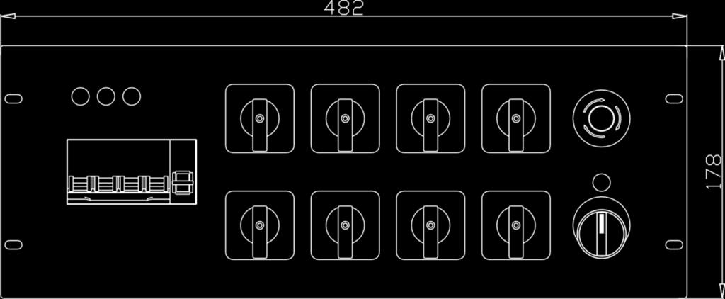
7 Description of the device Features The Showtec Showtec Chainhoist controller is a dedicated controller for all popular direct controlled chainhoists such as CM Lodestar. Each of the 8 hoists can be selected individually to go up or down or to be deselected as long as each individual motor output is rated for a maximum of 1kW and the total load of all motors summed should not exceed 6,9kW On the Backside: 4 x 4 pole CEE connectors and also 2x 16 pole multipin to connect a break/out box Power Supply: 400V 3~ + N +PE Max. voltage drop: -20% and +10% Power Connector: CEE 5 pole 32A Output Connector: CEE 4 pole 16A 2x 16 pole multi-connector (HARTING) Safety: Emergency button Compact strong metal housing Mains Circuit Breaker 4x 10A D Circuit breaker (for Run Switch +Stop button) 2A C Dimensions: 483 x 440 x 134 mm (LxWxH) Dimensions: 19" x 4U -5 degree Celsius till +40 degree Celsius Weight: 10,3 Kg Frontside 01) L1, L2, L3 Phase failure indication neon lamps 02) Mains switch 3 phase short circuit breaker (4x 10A D) 03) Short circuit protection for power and control (main circuit breaker, 2A C) 04) Up-0-Down switch for pre-selecting an individual hoist 05) Emergency button 06) Green RUN neon lamp 07) Run switch Fig. 01 6
 16-pole multi-connector (Harting) for Motor 1-4 09) 16-pole multi-connector (Harting) for Motor 5-8 10) 4x CEE 4 pole 16A socket 11) CEE 5 pole 32A Powerconnector Setup Possibilities")
8 Backside Fig ) 16-pole multi-connector (Harting) for Motor ) 16-pole multi-connector (Harting) for Motor ) 4x CEE 4 pole 16A socket 11) CEE 5 pole 32A Powerconnector Setup Possibilities PLE (70281) 1. 4x red CEE for Motor x Harting for Motor x Harting for Motor x Harting for Motor Motor 5-8 When the chainhoist controller is NOT used, disconnect the power cord. 7
9 Functional Description 01) Measure the main power supply and make sure the operating voltage is correct and all the phases are present and in correct order. 02) Check if the pre-selection switches for all hoists are in the "0" position. 03) Connect the chainhoists to the controller by either the using a HARTING 16p or the CEE connector. 04) Connect the controller to the powers supply by means of the 32A CEE plug. 05) Check that the emergency button is released. 06) Select a hoist and turn the switch in the up (1) or down (2) position. Turn the RUN switch to the right for 2 seconds to make sure the hoist has power. Also make sure that the running direction of the hoist matches the selected direction on your controller. The green LED lights up, when the black RUN switch is turned to the right. When the RUN switch is released, the green LED immediately dims and the switch will return to the OFF position. 07) If the direction of the hoist is not correct, change the phases. 08) If an individual hoist runs in the wrong direction. check the cabling and check the hoist. 09) Make sure that the load, that needs to be lifted, is in the correct position. 10) Clear the area from any obstacles that could jeopardize the operation. 11) No people are allowed under, on or in the vicinity of the load. Make sure all people have left the operating area, before you start to move any load. 12) Make sure you have an unobstructed view on the entire travel path of the load. Always keep an eye on the motors and workspace while operating the chainhoist controller. 13) Pre-select all hoists needed in the up or down direction. 14) Turn the black RUN switch to the right to activate all hoists and hold it until the load has reached the desired height. It may be necessary to level the rig at certain stages. 15) Never turn the RUN switch staccato (=often turning the Run switch within a few seconds). This can severely damage controller and hoist. 16) If the desired height is reached, release the RUN switch. When you release the Run switch, it will return to the OFF position. 17) Always disconnect power from the mains, when device is not used. NEVER change the running direction of a hoist when the run switch is turned All 3 red neon lamps L1,L2, L3 must be ON. Otherwise one of the phases is not present. Do NOT hoist. Only use cable and connectors, which are in good condition. Never connect more than one hoist per channel. Make sure that the total current draw of the connected devices, does not exceed the maximum allowed input current. This device is meant for professional use and should only be used in a professional environment. Follow all warnings and guidelines in this manual Otherwise it could cause severe injuries or even death!!!. 8
10 Installation Remove all packing materials from the Chainhoist controller. Check if all foam and plastic padding is removed. Connect all cables. Do not supply power before the whole system is set up and connected properly. Always disconnect from electric mains power supply before cleaning. Damages caused by non-observance are not subject to warranty. Installation shoud be done according national regulations. The Chainhoist controller has to be mounted between a minimum height of 0,8m and a maximum height of 1,60m, due to the presence of an emergency stop button. Set Up and Operation Follow the directions below, as they pertain to your preferred operation mode. Before plugging the unit in, always make sure that the power supply matches the product specification voltage. This is a versatile 10A three-phase, 8-way motor commander with two HARTING sockets or 4 CEE sockets for output loading. One 10 A residential circuit breaker and one 2 Amp MCB (main circuit breaker) are used for protection when a fault condition occurs or a voltage spike occurs. The Forward, Backward Rotation and Idle modes are available by turning the switch on the front of the controller. Forward Rotation / Up When the chainhoist controller is powered on, select the desired motor and set the switch to the "UP" (1) position to access the Forward Rotation. Then turn the "RUN" switch tot the right to start the forward/up movement. Backwards Rotation / Down When the chainhoist controller is powered on, select the desired motor and set the switch to the "DOWN" (2) position to access the Backward Rotation. Then turn the "RUN" switch tot the right to start the backward/down movement. Idle Position (0) When the chainhoist controller is powered on, select the desired motor and set the switch to the "0" position to access to the Idle position. All eight outputs are isolated and no operation is possible. Emergency Stop In case of an emergency immediately press the RED emergency "STOP" button. 9


11 Pin Assignment for a 16-pin Harting socket Maintenance The Showtec Chainhoist Controller requires almost no maintenance. However, you should keep the unit clean. Disconnect the mains power supply and then wipe the cover with a damp cloth. Wipe the front panel clean with mild detergent and a soft cloth. Do not use alcohol or solvents. The front panel will require weekly cleaning, as smoke-fluid tends to build up residues. Do not immerse in liquid. Keep connections clean. Disconnect electric power, and then wipe the connections with a damp cloth. Make sure connections are thoroughly dry before linking equipment or supplying electric power. The operator has to make sure that safety-relating and machine-technical installations are to be inspected by an expert after every year in the course of an acceptance test. The operator has to make sure that safety-relating and machine-technical installations are to be inspected by a skilled person once a year. The following points have to be considered during the inspection: 01) All screws used for installing the device or parts of the device have to be tightly connected and must not be corroded. 02) There may not be any deformations on housings, fixations and installation spots. 03) Mechanically moving parts like axles, eyes and others may not show any traces of wearing. 04) The electric power supply cables must not show any damages or material fatigue. 10
12 Troubleshooting This troubleshooting guide is meant to help solve simple problems. If a problem occurs, carry out the steps below in sequence until a solution is found. Once the unit operates properly, do not carry out following steps. Hoist(s) do not respond to the green RUN signal Please check the cabling and the connections The corresponding switch is set in the 0 position The main circuit breaker is OFF The red Emergency button is pressed Solution Connect everything properly Set the switch in the Up/Down position Set the main circuit breaker to ON Turn the emergency button clockwise to release. Controller does not respond Please check the powercable and the connections to the chainhoists. All 3 red neon lamps (L1, L2, L3) must be ON, Otherwise one of the phases is not present. DO NOT HOIST!! The main circuit breaker is switched OFF Control circuit breaker is switched OFF The red Emergency button is pressed The surrounding temperature is too high/too low Solution Connect everything properly. Please check all 3 phases Set the main circuit breaker to ON Set the switch to ON Control the area underneath the chainhoist for any emergency situation, if this is ok turn the emergency button clockwise to release Place the chainhoist controller in a cooler/warmer place If the problem is not solved, immediately return your device unit to an authorised dealer. 11

13 Exploded View 12
 14 Indicator(green) 15 Turn switch for emergency")
14 Parts 1 Top cover 2 Brass bar for E-line 3 Terminal block 4 Aluminum bracket for holding terminal 5 AC relay 6 Aluminum fix stand for remaining Relay 7 12-way connecting terminal block 8 ILME socket, female 9 Power outlet, CEE socket, 4-pin female 10 Chassis/Base case 11 Rubber case feet 12 MCB, 2-pole 13 Push knob for emergency stop(red) 14 Indicator(green) 15 Turn switch for emergency start(black) 16 Front panel 17 Universal Changeover Switch 18 Indicator(red) 19 MCB, 4-pole 20 Aluminum frame for fixing MCB 21 Cable nut 22 ILME chassis 23 Brass bar of terminal block 13
15 Connection Diagram 14

16 Declaration of Conformity 15
17 Product Specifications Model: Chainhoist controller Power Supply: 400V 3N~ +PE Max. voltage drop: -20% and +10% Max. Load per motor switch 1 kw (1,5A 400V) Max. load total, all outputs summed 6,9 kw (10A 400V) Rated Voltage of the assembly (Un) 400V Rated Insulation voltage (Ui) 500V Rated Impulse voltage (Uimp) 6kV Rated Current of the assembly (InA) 10A Rated peak withstand current (Ipk) 120A Rated conditional short circuit current of an assembly (Icc) 6kA Rated Diversity Factor (RDF) 1 Rated Frequency (fn) 50/60Hz Pollution Degree 3 Complies to standard IEC : 2011 Dimensions: 483 x 440 x 134 mm (LxWxH) Dimensions: 19" x 4 Weight: 10,3 Kg Operation Power Connector: Output Connector: Safety: Housing Mains Circuit Breaker Circuit breaker (for Run switch + Stop button) CEE 5 pole 32A 4x CEE 4 pole 16A 2x 16 pole multi-connector (HARTING) Emergency button Compact strong metal housing 4x 10A D 2A C Max. ambient temperature ta: 40 C Design and product specifications are subject to change without prior notice. Website: service@highlite.nl 16
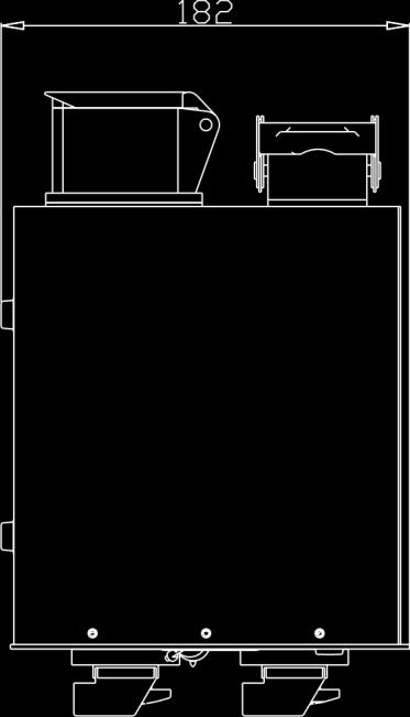

18 Dimensions 17
19 18
20 2015 Showtec
ENGLISH Bumper Waves
 MANUAL ENGLISH Bumper Waves V1 Highlite International B.V. Vestastraat 2 6468 EX Kerkrade the Netherlands Table of contents Warning... 2 Safety Instructions... 2 Operating Determinations... 4 Rigging...
FX Shot ORDERCODE 60908
 FX Shot ORDERCODE 60908 Highlite International B.V. Vestastraat 2 6468 EX Kerkrade The Netherlands Phone: +31 45-5667700 Congratulations! You have bought a great, innovative product from Showtec. The Showtec
Mini Aquatic ORDERCODE 30844
 Mini Aquatic ORDERCODE 30844 Congratulations! You have bought a great, innovative product from Showtec. The Showtec Mini Aquatic brings excitement to any venue. Whether you want simple plug-&-play action
Navigator ORDERCODE 40410
 Navigator ORDERCODE 40410 Congratulations! You have bought a great, innovative product from Showtec. The Showtec Navigator brings excitement to any venue. Whether you want simple plug-&-play action or
LED Pinspot 2. Snapshot. User Manual
 LED Pinspot 2 Snapshot Use on Dimmer Outdoor Use Sound Activated DMX Master/Slave Auto-ranging Power Supply Replaceable Fuse User Serviceable Duty Cycle User Manual 3000 N 29 th Ct, Hollywood, FL 33020
LED Pinspot 2. Snapshot. User Manual
 LED Pinspot 2 Snapshot Use on Dimmer Outdoor Use Sound-Activated DMX Master/Slave Auto-ranging Power Supply Replaceable Fuse User-Serviceable User Manual 5200 NW 108th Avenue, Sunrise, FL 33351 U.S.A.
Snapshot. User Manual BOB LED
 BOB LED Snapshot Use on Dimmer Outdoor OK Sound Activated DMX512 Master/Slave Autoswitching Power Supply Replaceable Fuse User Serviceable Duty Cycle User Manual 5200 NW 108th Avenue, Sunrise, FL 33351
Snapshot LX10 USER MANUAL. OK on Dimmer Outdoor OK Sound Activated DMX512 Master/Slave 115V/230V Switch Replaceable Fuse User Serviceable Duty Cycle
 LX10 Snapshot OK on Dimmer Outdoor OK Sound Activated DMX512 Master/Slave 115V/230V Switch Replaceable Fuse User Serviceable Duty Cycle USER MANUAL Chauvet, 3000 N 29 th Ct, Hollywood, FL 33020 U.S.A.
Snapshot LX5 USER MANUAL. OK on Dimmer Outdoor OK Sound Activated DMX512 Master/Slave 115V/230V Switch Replaceable Fuse User Serviceable Duty Cycle
 LX5 Snapshot OK on Dimmer Outdoor OK Sound Activated DMX512 Master/Slave 115V/230V Switch Replaceable Fuse User Serviceable Duty Cycle USER MANUAL Chauvet, 5200 NW 108th Avenue, Sunrise, FL 33351 U.S.A.
Snapshot. Use on Dimmer Outdoor Use Sound-Activated DMX Master/Slave 120 V/230 V Switchable Replaceable Fuse User-Serviceable.
 Snapshot Use on Dimmer Outdoor Use Sound-Activated DMX Master/Slave 120 V/230 V Switchable Replaceable Fuse User-Serviceable User Manual TABLE OF CONTENTS 1. BEFORE YOU BEGIN... 3 WHAT IS INCLUDED... 3
User Manual. Snapshot. Use on Dimmer. Outdoor Use. Sound Activated DMX 512. Master/Slave. 115/230V Power Switch. Replaceable Fuse.
 Snapshot Use on Dimmer Outdoor Use Sound Activated DMX 512 Master/Slave 115/230V Power Switch Replaceable Fuse User Serviceable Duty Cycle User Manual 3000 N 29 th Ct, Hollywood, FL 33020 U.S.A. (800)
1. Before You Begin What Is Included... 3 Unpacking Instructions Claims Product at a Glance... 3 Safety Instructions...
 User Manual TABLE OF CONTENTS 1. Before You Begin... 3 What Is Included... 3 Unpacking Instructions... 3 Claims... 3 Product at a Glance... 3 Safety Instructions... 4 2. Introduction... 5 Product Overview...
INSTALLATION INSTRUCTIONS. Mirror-ball 30 cm. For your own safety, please read this user manual carefully before you initial start-up.
 INSTALLATION INSTRUCTIONS Mirror-ball 30 cm For your own safety, please read this user manual carefully before you initial start-up. Every person involved with the installation, operation and maintenance
Models: EP EP EP EP EP EP USER MANUAL ENGLISH
 P R O F E S S I O N A L P O W E R A M P L I F I E R Models: EP - 300 EP - 500 EP - 800 EP - 1000 EP - 1300 EP - 1800 USER MANUAL ENGLISH WARNING FOR YOUR OWN SAFETY, PLEASE READ THIS USER MANUAL CAREFULLY
Snapshot. Hurricane 1300 USER MANUAL F-1300
 Hurricane 1300 F-1300 Snapshot OK on Dimmer Outdoor OK Sound Activated DMX512 Master/Slave 115V/230V Switch Replaceable Fuse User Serviceable Duty Cycle USER MANUAL 3000 N 29 th Ct, Hollywood, FL 33020
TABLE OF CONTENTS 1. BEFORE YOU BEGIN...
 User Manual TABLE OF CONTENTS 1. BEFORE YOU BEGIN... 3 What is Included... 3 Unpacking Instructions... 3 Product at a Glance... 3 Safety Instructions... 4 2. INTRODUCTION... 5 Product Overview... 5 Product
Snapshot Ok on Dimmer Outdoor OK Sound Activated DMX512 Master/Slave 115V/230V Switch Replaceable Fuse User Serviceable Duty Cycle
 SX Scope Snapshot Ok on Dimmer Outdoor OK Sound Activated DMX512 Master/Slave 115V/230V Switch Replaceable Fuse User Serviceable Duty Cycle USER MANUAL Chauvet, 3000 N 29 th Ct, Hollywood, FL 33020 U.S.A.
Event Spot WW Triac. User Manual. Order codes: LEDJ237 - Black Housing LEDJ237A - White Housing
 Event Spot WW Triac User Manual Order codes: LEDJ237 - Black Housing LEDJ237A - White Housing Safety advice WARNING FOR YOUR OWN SAFETY, PLEASE READ THIS USER MANUAL CAREFULLY BEFORE YOUR INITIAL START-UP!
CH-158 Color Bank 8 USER MANUAL
 CH-158 Color Bank 8 USER MANUAL CHAUVET, 3000 N 29 th Ct, Hollywood, FL 33020 U.S.A (800) 762-1084 (954) 929-1115 FAX (954) 929-5560 www.chauvetlighting.com TABLE OF CONTENT BEFORE YOU BEGIN... 3 WHAT
SpaceTracer 2000 CMY ORDERCODE 40961
 SpaceTracer 2000 CMY ORDERCODE 40961 Congratulations! You have bought a great, innovative product from Showtec. The Showtec SpaceTracer 2000 CMY brings excitement to any venue. Whether you want simple
USER MANUAL Table of Contents
 USER MANUA Table of Contents Safety Information... 3 Specifications... 4 Main Power Connection.....5 Main Control Menu.....5 Rigging the Fixture..6 Cleaning & Maintenance...6 Parts ist...7 Check that
Bubble King. User Manual
 Bubble King User Manual TABLE OF CONTENTS 1. Before You Begin... 3 What Is Included... 3 Unpacking Instructions... 3 Claims... 3 Text Conventions... 3 Icons... 3 Document Information... 3 Product at a
Verti Blast. User Manual. Order code: EQLED355
 Verti Blast User Manual Order code: EQLED355 Safety advice WARNING - FOR YOUR OWN SAFETY, PLEASE READ THIS USER MANUAL CAREFULLY BEFORE YOUR INITIAL START-UP! Before your initial start-up, please make
P/N Wheeler. user manual
 P/N 35000068 Wheeler user manual 1998, 1999 Martin Professional A/S, Denmark. All rights reserved. No part of this manual may be reproduced, in any form or by any means, without permission in writing from
HOME CHARGER MODE 2. Series to /32A single phase CONTENTS. Manual IMPORTANT SAFETY INSTRUCTIONS 3 SAFETY INFORMATION 4 INSTALLATION 5
 CONTENTS IMPORTANT SAFETY INSTRUCTIONS 3 SAFETY INFORMATION 4 INSTALLATION 5 OPERATION 8 SPECIFICATIONS 8 MAINTENANCE 9 HOME CHARGER MODE 2 Series 31328 to 31340 16/32A single phase FCC INFORMATION 9 WARRANTY
TABLE OF CONTENTS. Page 2 of 12 DataStream 4 User Manual Rev. 2
 User Manual TABLE OF CONTENTS 1. Before you Begin... 3 What Is Included... 3 Unpacking Instructions... 3 Claims... 3 Text Conventions... 3 Symbols... 3 Disclaimer... 3 Product at a Glance... 4 Safety Notes...
Stealth Power i-tilt
 Power Tilts OWNERS MANUAL Stealth Power i-tilt User Manual and Maintenance Guide for Stealth s i-tilt Customer Satisfaction 1.0 Stealth Products strives for 100% customer satisfaction. Your complete satisfaction
LED Twister II. User manual UK Version 1.0
 LED Twister II User manual 152.624UK Version 1.0 LED DUOPLEX: For indoor use only CAUTION! Please read this manual carefully before operating! Pay special attention to Sections 3 & 5 of this document.
Bubble Machine. User Manual
 Bubble Machine User Manual TABLE OF CONTENTS 1. Before You Begin... 3 What Is Included... 3 Unpacking Instructions... 3 Claims... 3 Text Conventions... 3 Icons... 3 Document Information... 3 Product at
Operators Manual. Recirculating Chiller /06/08
 Operators Manual Recirculating Chiller 110-197 11/06/08 Table of Contents Section 1. General Information 1.1 Warranty 1.2 Unpacking 1.3 Package Contents 1.4 Description of the Recirculating Chiller 1.5
SLA Battery Capacity Analyzer
 Model: 600B SLA Battery Capacity Analyzer USER MANUAL Safety Summary The following safety precautions apply to both operating and maintenance personnel and must be followed during all phases of operation,
Compact LED profile with zoom
 Compact LED profile with zoom 2 11 TABLE OF CONTENTS SAFETY / GENERAL INSTRUCTIONS INTRODUCTION Features Specifications OVERVIEW Rear view Top view MOUNTING CONTROL MENU OVERVIEW Control Panel Function
Contents. Introduction Inspection Notes on Safety Precautions. Chapter 1 Overview Product Overview Names of Parts 2
 INSTRUCTION MANUAL Contents Introduction Inspection Notes on Safety Precautions i i ii vii Chapter 1 Overview 1 1.1 Product Overview 1 1.2 Names of Parts 2 Chapter 2 Specifications 5 2.1 Product Specifications
User s Manual. Automatic Switch-Mode Battery Charger
 User s Manual Automatic Switch-Mode Battery Charger IMPORTANT Read, understand, and follow these safety rules and operating instructions before using this battery charger. Only authorized and trained service
24/3000H-3PH 24/4500H-3PH 24/6000H-3PH
 Manufacturer of Dimensions TM Inverters 4467 White Bear Parkway St. Paul, MN 55110 Phone: 651-653-7000 Fax: 651-653-7600 E-mail: inverterinfo@sensata.com Web: www.dimensions.sensata.com 120015D OWNERS
1100W PORTABLE GENERATOR
 1100W PORTABLE GENERATOR MODEL NO: G1200 PART NO: 8010110 OPERATION & MAINTENANCE INSTRUCTIONS LS0312 INTRODUCTION Thank you for purchasing this CLARKE 1100W Portable Generator. Before attempting to use
User Guide for Logo Projector
 User Guide for Logo Projector Professional Entertainment Technology . TABLE OF CONTENTS 1. Introduction 2. Safety Instruction 3. Description 4. Operation and Technical Specification 5. Lamp Installation
USER GUIDE LED LIGHTED MIRROR W/BUILT-IN MAGNIFIER. Model: , , ,
 USER GUIDE LED LIGHTED MIRROR W/BUILT-IN MAGNIFIER Model: 63662432, 63663632, 63664832, 63666028 IMPORTANT SAFETY INFORMATION Please read through this installation instruction so you will know how to install
Reach ins, Freeezers & Refrigerators Installation & Operation Manual
 Reach ins, Freeezers & Refrigerators Installation & Operation Manual BSR23 BSF23 BSR49 BSF49 BSR72 BSF72 IMPORTANT SAFETY INSTRUCTIONS (SAVE THESE INSTRUCTIONS) Visit us on the web at www.blueairinc.com
RT Series Step Down Transformer for RT Series UPS 6-10kVA UL Input Vac Output Vac User Guide
 RT Series Step Down Transformer for RT Series UPS 6-10kVA UL Input 208-240 Vac Output 208-120 Vac User Guide UNLESS SPECIFICALLY AGREED TO IN WRITING, SELLER (A) MAKES NO WARRANTY AS TO THE ACCURACY, SUFFICIENCY
Broadband PowerShield. External Battery Pack 20 Ah 12 V Battery. User Manual
 Broadband PowerShield External Battery Pack 20 Ah 12 V Battery User Manual 990-1660 08/2003 Chapter 1 General Information The APC PowerShield External Battery Pack connects directly to the APC PowerShield
PD-20 HIGH VOLTAGE PROBE INSTRUCTION MANUAL
 PD-20 HIGH VOLTAGE PROBE INSTRUCTION MANUAL Index 1. Safety precaution... 2. Specifications... 3. Operation... 4. Warning... 5. Cleaning... 6. Rated environmental conditions... 7. Observe the international
1. Before you Begin Introduction Setup Operation Technical Information Returns...12
 User Manual TABLE OF CONTENTS 1. Before you Begin... 3 What is Included... 3 Unpacking Instructions... 3 Claims... 3 Text Conventions... 3 Icons... 3 Document Information... 3 Product at a Glance... 4
Blue Air. Commercial Refrigeration Inc. Installation & Operation Manual Glass Door Countertop Refrigerator
 Blue Air Commercial Refrigeration Inc. Installation & Operation Manual Glass Door Countertop Refrigerator Please read this manual completely before installing or operating this unit! BAGR7 Blue Air reserves
Bus Station. PLEASE READ BEFORE USE AND SAVE
 Bus Station PLEASE READ BEFORE USE AND SAVE www.mthtrains.com CAUTION: ELECTRIC TOY: Not recommended for children under 14 years of age without adult supervision. As with all electric products, precautions
MP V 8A Electronic Smart Charger. Instruction and Information Manual
 MP7428 12V 8A Electronic Smart Charger Instruction and Information Manual In order to ensure correct and safe usage of your battery charger, you should read these instructions carefully. Please retain
C.fm Page 1 Thursday, February 21, :28 AM Raptor user manual
 Raptor user manual 1 mounting bracket 2 swivel lock 3 clamp hole 4 lamp access screws 5 air vents 6 AC input & main fuse 7 cooling fan Thank you for selecting the Martin Raptor. This Martin lighting fixture
User Manual Easy UPS BV Series 500VA, 650VA, 800VA, 1000VA Safety and General Information
 User Manual Easy UPS BV Series 500VA, 650VA, 800VA, 1000VA Safety and General Information SAVE THESE INSTRUCTIONS This manual contains important instructions that should be followed during installation
MANUAL. Single charger
 MANUAL Single charger HST-PR-2830 & HST-PR-2830USA for HS-Technik batteries HST-PR-18xx HST-PR-14xx issue date: November 2016 Table of contents Page 1. Basic information...3 1.1. Purpose of this document...3
ADI-125/750 ADI-125/1500 ADI-125/2500
 Manufacturer of Dimensions TM Inverters 4467 White Bear Parkway St. Paul, MN 55110 Phone: 651-653-7000 Fax: 651-653-7600 E-mail: inverterinfo@sensata.com Web: www.dimensions.sensata.com 121094B OWNERS
HyperFlex 12G.
 HyperFlex 12G USER MANUAL www.venuelightingeffects.com Table of contents Introduction...2 safety precautions...3 UNIT OVERVIEW...4 rigging the fixtures...4 Lamp Installation/Replacement...5 gobo Selection
HIGH VOLTAGE PROVING UNIT
 HIGH VOLTAGE PROVING UNIT INSTRUCTION MANUAL Index 1. Safety Precautions... 2. Specifications... 3. Features... 4. Connections... 5. Layout of Tester... 6. Instructions Label... 7. Proofing Methods...
IGLOO IGLOO EASY INSTRUCTION MANUAL
 ENGLISH EASY C695 C698 INSTRUCTION MANUAL Congratulations on choosing a Clay Paky product! We thank you for your custom. Please note that this product, as all the others in the rich Clay Paky range, has
DC Master 24/ A
 USERS MANUAL DC Master 24/12 50-60A DC-DC converter MASTERVOLT Snijdersbergweg 93, 1105 AN Amsterdam The Netherlands Tel.: +31-20-3422100 Fax.: +31-20-6971006 www.mastervolt.com ENGLISH Copyright 2015
READ AND SAVE THESE INSTRUCTIONS. ComfortBreeze UV360-1 SYSTEM 24V Ultra-Violet Air Cleaner. Trion
 READ AND SAVE THESE INSTRUCTIONS ComfortBreeze UV360-1 SYSTEM 24V Ultra-Violet Air Cleaner Trion www.trioniaq.com Installation, Operation, & Maintenance Manual 1. Warranty 2. Safety & Warnings ComfortBreeze
D.fm Page 1 Wednesday, March 5, :21 PM Raptor user manual
 Raptor user manual 1 mounting bracket 2 swivel lock 3 clamp hole 4 lamp access screws 5 air vents 2001-2002 Martin Professional A/S, Denmark. All rights reserved. No part of this manual may be reproduced,
Armon Edero. User manual
 User manual Armon Edero Foreword.... 2 Symbols used 2 Intended use.... 2 About the Armon Edero... 2 Mounting options of the Edero 2 Braces. 3 How to set up the Armon Edero.. 3 How to attach the brace to
Lemania/EnergyFlo Start booster X7
 Lemania/EnergyFlo Start booster X7 User Manual Always follow basic safety precautions and wear appropriate safety equipment when using electrical appliances and batteries. Read all instructions carefully.
Golden Mirrorball 15 cm / 20 cm
 INSTALLATION INSTRUCTIONS Golden Mirrorball 15 cm / 20 cm Für weiteren Gebrauch aufbewahren! Keep this manual for future needs! Copyright Nachdruck verboten! Reproduction prohibited! INSTALLATION INSTRUCTIONS
OWNERS MANUAL JANUARY 2007 ISO
 Manufacturer of Dimensions TM Inverters 4467 White Bear Parkway St. Paul, MN 55110 Phone: 651-653-7000 Fax: 651-653-7600 E-mail: inverterinfo@sensata.com Web: www.dimensions.sensata.com 121231B OWNERS
Lab Rotators and Low Cost Orbital Shakers
 Lab Rotators and Low Cost Orbital Shakers Model No. 2309, 2309JPN, 2309-1CE, 2309-1CECN 2314, 2314JPN, 2314-1CE, 2314-1CECN 2345, 2345JPN, 2345-1CE, 2345-1CECN 2346, 2346JPN, 2346-1CE, 2346-1CECN 057-325-00
DC to AC Power Inverters
 Manufacturer of Dimensions TM Inverters 4467 White Bear Parkway St. Paul, MN 55110 Phone: 651-653-7000 Fax: 651-653-7600 E-mail: inverterinfo@sensata.com Web: www.dimensions.sensata.com ISO 9001:2000 Certified
SOS SERIES SOS1 SOS2. Spares On Site Battery Cabinet Installation Guide rEV3
 Atlantic Battery Systems 1065 Market Street Paterson, NJ 07513 Phone: (800) 875-0073 Fax: (973) 523-2344 sales@atbatsys.com www.atbatsys.com SOS1 SOS2 SOS SERIES Spares On Site Battery Cabinet Installation
DC to AC Power Inverters
 Manufacturer of Dimensions TM Inverters 4467 White Bear Parkway St. Paul, MN 55110 Phone: 651-653-7000 Fax: 651-653-7600 E-mail: inverterinfo@sensata.com Web: www.dimensions.sensata.com 121114C OWNERS
PRO Dimmer INSTRUCTION MANUAL
 PRO Dimmer 2,000 WATT PRECISION AC DIMMER INSTRUCTION MANUAL McIntire Enterprises, Inc. 12986 Mapleleaf Ct. NE. Aurora, OR 97002-8418 Phone: 503-678-6236 www.magicgadgets.com benchtech@magicgadgets.com
PRM-2 PHASE SEQUENCE TESTER PRM-3 PHASE SEQUENCE & MOTOR ROTATION TESTER User s Manual
 PRM-2 PHASE SEQUENCE TESTER PRM-3 PHASE SEQUENCE & MOTOR ROTATION TESTER User s Manual 99 Washington Street Melrose, MA 02176 Fax 781-665-0780 TestEquipmentDepot.com CONTENTS PRM-2 & PRM-3 1. Warranty...3
Effective June 1, 2013 This guide supersedes all previous versions
 Effective June 1, 2013 This guide supersedes all previous versions 3842 Redman Drive 1-800-797-7974 Fort Collins, CO 80524 www.commandlight.com L-CAS THANK YOU Please allow us to express a simple thank
Switching DC Power Supply
 99 Washington Street Melrose, MA 02176 Phone 781-665-1400 Toll Free 1-800-517-8431 Visit us at www.testequipmentdepot.com Model 1693, 1694 Switching DC Power Supply INSTRUCTION MANUAL 1 Safety Summary
Model 1693, 1694 Switching DC Power Supply
 Model 1693, 1694 Switching DC Power Supply INSTRUCTION MANUAL 1 Safety Summary The following safety precautions apply to both operating and maintenance personnel and must be observed during all phases
RS-3 PRO RS-1007 PRO. CAT IV Analog Clamp meter Series. Users Manual. For detailed specifications and ordering info go to
 RS-3 PRO RS-1007 PRO CAT IV Analog Clamp meter Series Users Manual For detailed specifications and ordering info go to www.testequipmentdepot.com RS-3 PRO RS-1007 PRO CAT IV Analog Clampmeter Series English
Power InverterTM Watt. Continuous. User's Manual. WAGAN Corp. Limited Warranty Registration Form. Item no
 WAGAN Corp. Limited Warranty Registration Form All WAGAN Corporation products are warranted to the original purchaser of this product. Warranty Duration: This product is warranted to the original purchaser
Measurements are expressed in millimeters.
 T-Rex user manual Measurements are expressed in millimeters. 1 Lamp access 2 Focus adjustment 3 Mounting bracket 4 Swivel locks 5 Clamp hole 6 Air vent 190 285 7 AC input & main fuse 8 Microphone 490 164
Technical Information Manual
 Technical Information Manual Revision n. 4 18 June 2008 MOD. A3000NF 3-PHASE NOTCH FILTER MANUAL REV. 4 NPO: 00120/04:3000N.MUTx/04 CAEN will repair or replace any product within the guarantee period if
Model 1672, 1673 Triple Output Power Supply
 Model 1672, 1673 Triple Output Power Supply INSTRUCTION MANUAL 1 Safety Summary The following safety precautions apply to both operating and maintenance personnel and must be observed during all phases
SENSE SERIES SPEAKERS
 SENSE SERIES SPEAKERS User Manual 2018 ADJ PRODUCTS, LLC all rights reserved. Information, specifications, diagrams, images, and instructions herein are subject to change without notice. ADJ and SENSE
HTR-202 INSTRUCTION MANUAL. Portable Digital Height Rod. Befour, Inc. 102 Progress Drive Saukville, WI 53080
 Befour, Inc. 102 Progress Drive Saukville, WI 53080 Phone: 262-284-5150 Toll Free: 1-800-367-7109 Fax: 262-284-5966 Email: mail@befour.com www.befour.com 2014 Befour, Inc. Rev.1 HTR-202 Portable Digital
INSTRUCTION & INSTALLATION
 INSTRUCTION & INSTALLATION MANUAL MODELS: CCL-eHOME T1C16 CCL-eHOME T1C32 CCL-eHOME T2C16 CCL-eHOME T2C32 WALLBOX ehome SERIES WALLBOX ehome Instruction and Installation manual This document is copyrighted,
OPERATING INSTRUCTIONS. Note: 6V Charging. Requires Manual Shut Off.
 Requires Manual Shut Off. 6 / 2 AMP,, DUAL RATE BATTER TTERY CHARGER 45005 OPERATING INSTRUCTIONS E224783 E224783 Note: 6V Charging Due to continuing improvements, actual product may differ slightly from
PATRIOT INSTRUCTION MANUAL FMGRID-16, FMGRID-24, FMGRID-30 ELECTRIC GRIDDLES
 INSTRUCTION MANUAL FMGRID-16, FMGRID-24, FMGRID-30 ELECTRIC GRIDDLES This manual contains importatant information regarding your Patriot unit. Please read this manual thoroughly prior to equipment set-up,
XPC-EBP64 External Battery Pack User & Installation Manual Xtreme Power Conversion Corporation. All rights reserved.
 XPC-EBP64 User & Installation Manual www.xpcc.com 2015. All rights reserved. (Rev 9/28/15) Table of Contents Introduction...5 Product Description...5 Extended Battery Pack Configurations...6 Safety Information...7
HOME BOX EV CHARGING STATION WITH FIXED CABLE
 12 C O N T A C T / C U S T O M E R S U P P O R T HOME BOX EV CHARGING STATION WITH FIXED CABLE Ratio Electric B.V. Ambachtsstraat 12 NL-3861 RH Nijkerk The Netherlands Tel. +31-33-2452360 info@ratio.nl
Blue Air. Commercial Refrigeration Inc. Installation & Operation Manual Chef Bases
 Blue Air Commercial Refrigeration Inc. Installation & Operation Manual Chef Bases Please read this manual completely before installing or operating this unit! BACB53 BACB71 BACB74 BACB83 BACB86 BACB96
PrioVino Premier. Translation of Original Operating Instructions. Status: August First edition January 2018 / PrioVino GmbH
 PrioVino Premier Translation of Original Operating Instructions Status: August 2018 First edition January 2018 / PrioVino GmbH Reprint even in extracts only upon written permission by PrioVino GmbH (ISO
Gavita HortiStar 600 SE EU
 Pro line Gavita HortiStar 600 SE EU Horticultural design HortiStar 600 HR 96 reflector Reflector efficiency 96 % Easily replaceable reflector Shielded cord terminal For HPS/MH lamps up to 750 W Gavita
PURE SINE WAVE DC TO AC POWER INVERTER
 PURE SINE WAVE DC TO AC POWER INVERTER 60S-12A / 60S-24A 60S-12E / 60S-24E 100S-12A / 100S-24A 100S-12E / 100S-24E 150S-12A / 150S-24A 150S-12E / 150S-24E Instruction manual SINE WAVE INVERTER Please read
Dimensions 12/800N 12/1200N D. DC to AC Power Inverters. OWNERS MANUAL for Models: OWNERS MANUAL April ISO 9001:2000 Certified Company
 Manufacturer of Dimensions Inverters 4467 White Bear Parkway St. Paul, MN 55110 Phone: 651-653-7000 Fax: 651-653-7600 E-mail: inverterinfo@sensata.com Web: www.dimensions.sensata.com OWNERS MANUAL April
MIL-24/2600Q MIL-24/3200DQ
 Manufacturer of Dimensions TM Inverters 4467 White Bear Parkway St. Paul, MN 55110 Phone: 651-653-7000 Fax: 651-653-7600 E-mail: inverterinfo@sensata.com Web: www.dimensions.sensata.com 121473B OWNER'S
5.5KVA GENERATOR MODEL NO: PG6500DVES OPERATION & MAINTENANCE INSTRUCTIONS PART NO: LS0616
 5.5KVA GENERATOR MODEL NO: PG6500DVES PART NO: 8857810 OPERATION & MAINTENANCE INSTRUCTIONS LS0616 INTRODUCTION Thank you for purchasing this CLARKE 5.5KVA Generator. Before attempting to use this product,
Pure Spot 120LED USER MANUAL.
 Pure Spot 120LED USER MANUAL www.bsl-lighting.com Table of contents 1. Safety instructions... 3 2. Operating determination... 4 3. Fixture exterior view... 5 4. Installation... 6 4.1 Connection to the
Defender 3000 Series Base Instruction Manual
 Defender 3000 Series Base Instruction Manual 99 Washington Street Melrose, MA 02176 Phone 781-665-1400 Toll Free 1-800-517-8431 Visit us at www.testequipmentdepot.com Compliance This product conforms to
3KVA DUAL VOLTAGE GENERATOR MODEL NO: PG3800DV
 3KVA DUAL VOLTAGE GENERATOR MODEL NO: PG3800DV PART NO: 8857815 OPERATION & MAINTENANCE INSTRUCTIONS LS1016 INTRODUCTION Thank you for purchasing this CLARKE 3KVA Dual Voltage Generator. Before attempting
SDM320D / SDM320A. Single phase din rail meter SDM320D / SDM320A user manual
 SDM320D / SDM320A DIN Rail Single Phase Two Wire Energy Meter with S0 Pulse Output (Four modular) User Manual ------------------- 1.1 Safety instruction 1.2 Introductions 1.3 Performance criteria 1.4 Specifications
Cordless Rechargeable Saw Instructions for Use
 Technical data Voltage: DC 10.8V Weight: 1.25Kg Stroke rate: 0-2100/min Stroke: 15mm Cutting capacity: max diameter in wood 80mm / in soft metal 7mm Charging time: Between 5.0-5.5 Hours Battery: 1.3Ah
User Manual Stealth s Power Tilt
 User Manual Stealth s Power Tilt Copyright 2014 Stealth Products, Inc. Copyright 2014 Stealth Products, Inc. All rights reserved. Published by Stealth Products, Inc. November 7, 2014 P45D61R1 Customer
LED-6200T 144 LED VARIABLE COLOR ON-CAMERA LIGHT USER MANUAL
 LED-6200T 144 LED VARIABLE COLOR ON-CAMERA LIGHT USER MANUAL LED-6200T INTRODUCTION Thank you for choosing the Genaray LED-6200T On-Camera Light. This product will provide you with powerful, portable and
DIGITAL BATTERY TORQUE WRENCH (BC-RAD SELECT) USER GUIDE
 USER GUIDE") DIGITAL BATTERY TORQUE WRENCH (BC-RAD SELECT) USER GUIDE W.CHRISTIE (INDUSTRIAL) LTD CHRISTIE HOUSE, MEADOWBANK ROAD, ROTHERHAM, SOUTH YORKSHIRE, S61 2NF, UK T: +44(0)1709 550088 F: +44(0)1709 550030 E:
DIGITAL BATTERY TORQUE WRENCH (BC-RAD SELECT) USER GUIDE W.CHRISTIE (INDUSTRIAL) LTD CHRISTIE HOUSE, MEADOWBANK ROAD, ROTHERHAM, SOUTH YORKSHIRE, S61 2NF, UK T: +44(0)1709 550088 F: +44(0)1709 550030 E:
OPERATING INSTRUCTIONS
 OPERATING INSTRUCTIONS A.W. Sperry Instruments Inc. AC SNAP-AROUND WITH DC VOLT RANGE MODELS TD-2608 & TD-2608A 1) FEATURES UL Listed Five Functions, 12 Ranges. Tear drop shaped jaws for ease of use in
BP1204 INSTALLATION/OWNER'S MANUAL
 BP1204 INSTALLATION/OWNER'S MANUAL BP1204 PREPARATION Getting Started Thank you for purchasing the Dual Electronics BP1204 Bandpass Subwoofer System. Although Dual has attempted to ensure the information
Megohmmeter Test Probe
 Megohmmeter Test Probe User Manual ENGLISH www.aemc.com CHAUVIN ARNOUX GROUP Copyright Chauvin Arnoux, Inc. d.b.a. AEMC Instruments. All rights reserved. No part of this documentation may be reproduced
TS69 TS65 TS55 TS45 TS5768 TS SERIES INSTALLATION/OWNER'S MANUAL
 TS69 TS65 TS55 TS45 TS5768 TS SERIES INSTALLATION/OWNER'S MANUAL Car Audio Speakers TS SERIES PREPARATION Getting Started Thank you for purchasing the TS Series car speakers. Although Dual has attempted