Brake motors ISO 9001: Certified Quality System
|
|
|
- Warren Day
- 6 years ago
- Views:
Transcription
1 BRAKEMOTORES 3F
2 Brake motors ISO 01: 0 Certified Quality System
3 Index BA series General Characteristics 2 GENERAL INFORMATION PRODUCT RANGE: POWER AND POLE MOTOR DESIGNATION STANDARDS AND APPROVALS CE MARK UL - CSA STANDARDS AND APPROVAL CCC CERTIFICATION MOTOR IDENTIFICATION NAMEPLATE TOLERANCES STANDARD AND SPECIAL FLANGE TYPE OF COSTRUCTIONS AND MOUNTING ARRANGEMENTS ENCLOSURE RATINGS BEARINGS RECTIFIERS VOLTAGE AND FREQUENCY SUPPLY OPERATING AT HZ DUTY TYPES MOTOR RUNNING ON INVERTER BALANCING NOISE TEMPERATURE, ALTITUDE, HUMIDITY PROTECTION DEVICES BA SERIES GENERAL CHARACTERISTICS BA SERIES BRAKE GROUP AIR GAP ADJUSTMENT BRAKE TORQUE ADJUSTMENT PERMISSIBLE STARTING FREQUNCY WITH LOAD BRAKE COIL WIRING CONNECTION BRAKE TORQUE AND BRAKE SPRINGS COMPRESSION TECHNICAL DATA SINGLE SPEED SINGLE WINDING MOTORS, (2, 4 POLES) TECHNICAL DATA SINGLE SPEED SINGLE WINDING MOTORS, (6, 8 POLES) TECHNICAL DATA TWO SPEED MOTORS SINGLE WINDING, (2 / 4 POLES) TECHNICAL DATA TWO SPEED SINGLE WINDING MOTORS, (4 / 8 POLES) TECHNICAL DATA TWO SPEED TWO WINDING MOTORS, (2 / 6 POLES) TECHNICAL DATA TWO SPEED TWO WINDING MOTORS, (2 / 8 POLES) TECHNICAL DATA TWOSPEED TWO WINDING MOTORS, (4 / 6 POLES) TECHNICAL DATA TWO SPEED TWO WINDING MOTORS, (4 / 12 POLES)
4 Index TECHNICAL DATA TWO SPEED TWO WINDING MOTORS, (2 / 12 POLES) HOISTING MOTORS 4 / 16 POLES BRAKE LININGS WEAR STARTING AND BRAKING TIME BA SERIES DIMENSIONS BA series BM SERIES GENERAL CHARACTERISTICS BM BRAKE GROUP AIR GAP ADJUSTMENT PERMISSIBLE STARTING FREQUENCY WITH LOAD BRAKE REACTION TIME AND RECTIFIER WIRING DIAGRAMS BRAKING TIME CALCULATION TECHNICAL DATA SINGLE SPEED SINGLE WINDING MOTORS (2, 4 POLES) TECHNICAL DATA SINGLE SPEED SINGLE WINDING MOTORS (6, 8 POLES) TECHNICAL DATA TWO SPEED SINGLE WINDING MOTORS (2 / 4, 4 / 8 POLES) TECHINICAL DATA TWO SPEED TWO WINDING MOTORS (2 / 6, 2 / 8 POLES) TECHNICAL DATA TWO SPEED TWO WINDING MOTORS (4 / 6, 4 / 12 POLES) BM SERIES DIMENSIONS BM series TRAVERSE MOTORS WITH PROGRESSIVE START AND STOP (PV SERIES) HOISTING MOTORS (BAPK SERIES) PREMIUM BRAKE TORQUE (BAF SERIES) FORCED COOLING MOTORS (SV SERIES) BUILT-IN ENCODER MOTORS (E SERIES) BAE SERIES DIMENSIONS BMEAV SERIES DIMENSION BUILT-IN INVERTER MOTORS BUILT-IN INVERTER MOTORS SPECIFICATIONS DOUBLE BRAKE MOTORS (BMBM SERIS) BMBM SERIES DIMENSIONS MOTORS FOR USA AND CANADA MOTORS FOR AUSTRALIA AND NEW ZEALAND MOTORS FOR CHINA PACKAGING TERMS AND CONDITIONS OF SALE AND WARRANTY SPECIAL FEATURES AND OPTIONS SPARE PARTS BA SERIES SPARE PARTS BM SERIES 3
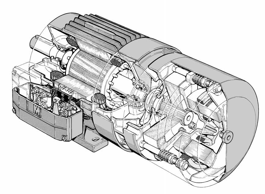
5 GENERAL INFORMATION GENERAL CHARACTERISTICS MGM brake motors are asynchronous three-phase totally enclosed fan cooled motors. The motor brakes in case of power supply failure. The braking action is always obtained through a very quick and precise stop and it guarantees a safe and prompt intervention in case of an unintentional power supply failure. The braking action is obtained without shaft axial sliding and it provides equal braking torque in both directions of rotation. MGM brake motors are particularly suitable for hoisting and traverse machines, tooling machinery, automatic and transfer machinery in textile, ceramic and packing fields and in all those situation where precision and quickness in braking are required. MGM brake motors are designed and assembled as real brake motors. The perfect engineering and assembling combined with a strong and safe brake, make these motors very reliable. As standard, on the IM B3 mounting (foot mounted), feet are integrated in the frame (they are not attached to the frame) making the motor very sturdy. This feature is very important on those brake motor applications where the stress during start/stop is very high. The brake disc lining material is asbestos free with high friction coefficient and very long lasting. The motors are provided with IP 4 enclosure rating and insulation class F. On request they can be provided with IP or IP 6 enclosure ratings and with class H insulation. All MGM motors are designed for inverter duty. On request it is possible to supply the motor with the encoder fitted on the second shaft end or to have the second shaft end ready to fit an encoder. For further information please refer to the encoder series section. MGM brake motors series are: BA and BM. BA series The BA series consists of three phase, asynchronous brake motors totally enclosed fan cooled. The BA series range starts from 71 up to 22 frame size. As standard, the brake power supply is AC 3-phase. On request DC brake can be provided with a rectifier integrated in the terminal box. The rectifier is provided with an over-voltage and radio frequency emission protection device. All BA series motors are provided with manual brake release. The BA series cooling fan is fitted between the motor and the braking assembly. The brake moving element and the brake coil have a laminated magnetic nucleus to reduce losses and to allow very fast braking. BA series main features are a very quick braking action, both in unlocked and high torque braking, a constant braking time and a very high number of start/stop cycles also under severe applications. BM series The BM series consists of three phase, asynchronous brake motors totally enclosed fan cooled. The BM series range starts from 6 up to frame size. As standard the brake power supply is DC with a rectifier integrated in the terminal box. The rectifier is provided with an over-voltage and radio frequency emission protection device. The cooling fan is fitted at non-drive shaft end. BM series main features are low braking noise, gradual acceleration during the motor start and stop and the reduced overall dimensions. The BA and BM series are also available in the following main versions: PV (BAPV, BMPV): with fly-wheel that allow progressive start and stop, particularly suitable for traverse application. F (BAF): with double brake disc and extremely high brake torque. AV-SV with forced cooling (BMAV with axial forced cooling, BASV with double radial forced cooling) 4
6 Product range The table below shows the brake motors production range of BM, BA motor series. Motor Type 6 A 6 B A B C D 71 A 71 B 71 C 71 D A B C SA SB LA LB LC LA LB 112 MB 112 MC 132 SA 132 SB 132 MA 132 MB 132 MBX MA MB LA LB 1 LA 1 LB LA LB 22 S 22 M 22 MX Series BM BM BM BM BM BM BM BA BM BA BM BA BM BA BM BA BM BA BM BA BM BA BM BA BM BA BM BA BM BA BM BA BM BA BM BA BM BA BM BA BM BA BM BA BM BA BM BA BM BA BM BA BM BA BM BA BA BA BA BA BA BA BA 2 pole kw pole kw pole kw pole kw / 4 pole kw 0.22/ / / / / /0. 1.3/0.9 /1.2 /1. /1. 3.1/ 4./3.3.0/4. /.0 7./ 9./ 11.0/9.0 1/11.0 1/.0./1 2/.0 3/30.0.0/3.0 4 / 8 pole kw 0.13/ / / / /0.2 0./ / /0.9 /1.2 / / / 6./4. 9./ 11.0/.0/9.0 1/ /1 30.0/1 3.0/2.0 2 / 6 pole kw 0.2/ / / / / / /0. 1.6/0.6 /0.8 /1.0 /1.3./ / / 11.0/3.6 1/6. 2 / 8 pole kw 0.18/ / / / / / / / /0.4 /0. /0.8 /1.1./1. / / 11.0/ 1/ 18./4. 2/ 30.0/7. 4 / 6 pole kw 0.18/ / /0.2 0./ /0. 1.1/0.8 1./1.0 /1.3 /1. / 3.7/./3.7 7./ /7. 1/ /. 4 / 12 pole kw S3 % 0.2/ / / / / / /0.3 1./0. /0.8 /1.0 / / / 2 / 12 pole kw S3 % 0./ / /0.1 /0.2 /0. /0.6./0.9 /1.1 /1.3** 11.0/** 1/ 4 / 16 pole kw S4 % - 4 pole S4 2% - 16 pole /0.7 /1.1./1.3** 7.3/**.0/** 13.2/ 1/ 19.0/4.8 2/ GENERAL CHARACTERISTICS ** Powers available for BA series only Note: All the above motors can be provided in the standard execution, without the brake also with a servo fan, built-in encoder or builtin inverter.
7 Motor Designation GENERAL CHARACTERISTICS The following technical characteristics are used to correctly identify MGM motors: Series Frame size Power and poles Mounting Voltage and frequency BM, BA mm kw poles 2 See mounting section According to customer request example: BA example: 71 example: 0.37 kw 4 poles or B 4 (see technical data) example: IM B example: 230/0V 0 Hz Brake supply Insulation class Enclosure AC or DC 3 Single or double terminal board box 4 F or H IP4, IP, IP6 3 example: AC brake coil, double terminal board box for separate brake supply example: class F example: IP 4 It is necessary to indicate any special features or options not supplied as standard (see page 9), such as reduced diameter flanges, thermal protectors, tropical environment execution, etc. Unless otherwise specified, the brake supply voltage is the same as the motor voltage. Unless otherwise specified, the DC brake voltage supply is 230V 0/ Hz. 1 The BM, BA series are also available in the versions BMPV, BAPV with soft start and stop suitable for traversing, and the version BMSV, BASV with forced cooling fan. The BA series is also available in the version BAF, with double brake disc and premium brake torque. 2 In two speed motors, the model number is followed by the letter D on motors with Dahlander winding, and by the letters DA on motors incorporating two separate windings (i.e. BADA 71 B 2/8). 3 BA series motors are available with both DC and AC brakes while BM series motors are available with only DC brakes. DC brake motors with power supply higher than 24 Volts have as standard a rectifier with emission suppression. 4 Single speed motors can be provided with a single terminal board box with the motor and brake power terminals connected in parallel, or with a double terminal board, having the motor supplied separately from the brake. Unless otherwise specified, single speed motors up to 112 frame size are provided with just one terminal board. Motors with frame size 132 and above are provided as standard feature with a double terminal board box. On two speed motors, the motor power supply is always separate from the brake power supply. On single speed motors with separate brake power supply a double terminal board box has to be provided. A double terminal board box also has to be provided on motors with the following options or auxiliary devices: thermo protectors, thermistors (PTC), standstill heaters, forced cooling, IP 6 enclosure, EMI filters, DC brake with brake power supply higher than 24V, brake voltage different from motor voltage, motor voltage 0/6V 0Hz, encoder, microswitch, side terminal box. Example BA 71 B4, 230/0V 0 Hz, class F, IP 4, IM B, AC brake coil, double terminal board box. 6
8 Standard and approvals Description IEC CENELEC CEI / UNEL BS NFC DIN / VDE DEC Ratings and operating characteristics Methods for determining losses and efficiency using tests Cooling methods for rotating electrical machines Terminal markings and direction of rotation of rotating machines IEC 34-1 IEC 34-2 IEC 34-6 IEC 34-8 EN EN EN EN CEI 2-3 CEI 2-6 CEI 2-7 CEI 2-8 BS BS BS BS NFC NFC 1 - NFC NFC VDE VDE DIN IEC 34-6 VDE UNE UNE 116 UNE 12 UNE 1-8 GENERAL CHARACTERISTICS Characteristics of mountings and types of installation IEC 34-7 EN CEI 2 - BS NFC DIN IEC 34-7 UNE 112 Starting behaviour of asynchronous three phase single speed cage motors, at 0 Hz and with power supply up to 6 V IEC EN CEI 2-1 BS VDE Classification of protection degree of rotating electrical machines IEC 34 - EN CEI 2-16 BS NFC 1-11 VDE UNE Mechanical vibrations of machines with shaft height from 6 mm. Measurement, assessment and limits of vibration intensity IEC 34 - EN CEI 2-23 BS NFC DIN ISO 2373 Fixing dimensions and rating powers for IM B3 motors and derivatives IEC 72 HD 231 EN 03 UNEL CEI 2-31 BS NFC 1-1 DIN UNE 6 Fixing dimensions and rating powers for IM B motors and derivatives IEC 72 HD 231 EN 03 UNEL 13117/13118 CEI 2-31 BS NFC 1-1 DIN UNE 6 Noise level, limit values IEC 34-9 EN CEI 2-24 BS NFC VDE Mark MGM brake motors have the mark on the nameplate to indicate the conformity to the requirements of 73/23 EEC Low Voltage Directive and 89/336 EEC Electromagnetic Compatibility Directive, with their subsequently amendments EEC 92/31 and 93/68 EEC. CSA approval and UL standards On request MGM motors can be provided with ccsaus approval in conformity with the requirements of UL 4 Electric motors and CSA C 2 No. Motors and generators for the North American market. The approved motors show the mark on the nameplate. CCC approval On request MGM motors can be provided with CCC (China Compulsory Certification) approval for the Chinese market. The approved motors show the mark on the nameplate. 7
9 Motor identification nameplate GENERAL CHARACTERISTICS Every motor is provided with an identifying nameplate, on which specific motor information is given. Motor nameplates are shown below with motor data and explanatory notes. The nameplate shown on the left is used for single speed motors while the nameplate on the right is used for two speed motors. MGM motori elettrici s.p.a. Serravalle Pistoiese (PT) ITALIA CE I 2771 Mot. 3 1 IP 2 Ins. CL 3 Kg 4 TYPE N 6 Brake Max. Nm 7 I Brake 8 Hz 0 kw Hz kw cos ϕ 11 min cos ϕ 18 min Y Y 13 1 VOLT AMP IEC 34-1 (1994) 9 17 MGM motori elettrici s.p.a. Serravalle Pistoiese (PT) ITALIA Mot. 3 1 IP 2 Ins. CL 3 Weight Kg 4 TYPE N 6 Brake Max. Nm 7 I Brake 8 Hz 0 kw min -1 V 24 cos ϕ 11 A Hz kw 17 min -1 V 26 cos ϕ 18 A IEC 34-1 (1994) CE I Duty type Enclosure rating Insulation Class, the letters TR following the insulation class means tropicalized treatment Weight (Kg) Motor type Designation Serial Number Maximum Static Brake Torque obtainable with proper regulation of the springs (Nm) Brake Current (A) Brake Voltage Supply (V). On brake motors with D.C. brake the voltage supply follows the note DC BRAKE. On brake motors with AC brake the symbol Vb = Vm indicates that the motor and brake have the same voltage supply. For motors with additional cooling fans, the fan voltage supply is shown in this location, preceded by the letters VENT. The letters TP indicate the presence of bimetallic thermal protectors, TM indicate thermistors, and SCALD indicates anti-condensation heaters, all followed by the voltage supply. Rated Power (kw) at 0 Hz Power Factor at 0 Hz Motor Speed (RPM) at 0 Hz Motor Voltage Supply at 0 Hz, Delta connected Motor Amps at 0 Hz, Delta connected Motor Voltage Supply at 0 Hz, Star connected Motor Amps at 0 Hz, Star connected Rated Power (kw) at Hz Power Factor at Hz Motor Speed (RPM) at Hz Motor Voltage Supply at Hz, Delta connected Motor Amps at Hz, Delta connected Motor Voltage Supply at Hz, Star connected Motor Amps at Hz, Star connected 8
10 Tolerances Electromechanical Characteristics The table below, describes the electromechanical tolerances concerning electric motors, according to the IEC 34-1 standard (EN 034-1). Parameter Efficiency Power Factor Locked Rotor Current Moment of Inertia Locked Rotor Torque cosϕ Tolerance 0.1 (1 - η) Rated power 0 kw (1 - cos ϕ) / 6 min 0,02 - max 0,07 Slip ±30% Rated power <1kW ±% Rated power 1kW +% ±% of the guarateed value 1% of the guarateed value +2% of the guarateed value (Upon request it is possibile to exceed the +2% value) Mechanical tolerances The table below describes the mechanical tolerances concerning electric motors, according to the standard IEC 72. Dimension Tolerance GENERAL CHARACTERISTICS Shaft Height Flange Spigot Shaft End Diameter 0, mm j6 for motors up to 132 frame size h6 for motors of frame size and above j6 from 39 mm up to 28 mm k6 from mm up to 48 mm m6 from mm up to mm The table below shows the dimension of the standard and special flange and shaft sorted by frame size. Standard and special flange E P N B P N B M M Motor frame size Shaft drive end dimension (DxE) (mm) Flange type Flange dimension (P/M/N) (mm) BM 6 9x B (standard) 1// BM 6 9x B (standard) /6/0 BM 11x23 B (standard) 0/11/9 BM 11x23 B (standard) // BM 11x23 B-R (6) () /6/0 *** BA 71 x30 B (standard) /130/1 BA 71 x30 B-R (6)* 1// BA 71 x30 B-R/M ()* 0/11/9 BA 71 x30 B-M /16/130 BA 71 x30 B (standard) /8/70 BA 71 x30 B-R () // *** BA 19x B(standard) /16/130 BA 19x B-R /130/1 BA 19x B 1// BA 19x B-R () 1/8/70 *** BA 24x0 B(standard) /16/130 BA 24x0 B-R /130/1 BA 24x0 B(standard) 0/11/9 BA 24x0 B-R (1) 0// *** BA 28x B(standard) /21/1 BA 28x B-R ** /16/130 BA 28x B(standard) /130/1 BA x B (standard) /21/1 BA x B(standard) /130/1 BA 132 x B(standard) /26/230 BA 132 x B-R /21/1 BA 132 x B(standard) /16/130 BA 42x1 B(standard) 30// BA 1 48x1 B(standard) 30// BA x1 B(standard) 0/30/ BA 22 x0 (4/6/8 Poles) B(standard) 0/0/30 BA 22 x1 (2 Poles) B(standard) 0/0/30 Notes: * This type of flange requires a special shaft therefore it isn t interchangeable with the standard flanges. This flange increases the motor length (Q) by 2mm. ** This type of flange requires a non standard bearing while the shaft remains the standard one. *** The difference between the dimension of the reduced flange and the standard one (in brackets) doesn t affect the correct motor assembly. D 9
11 Type of construction and mounting GENERAL CHARACTERISTICS The table below shows the most important types of mounting arrangements according to IEC 34-7 (EN 034-7) standard. Two systems of classification are provided: code 1 (the alpha-numeric designation) and code 2 (the all numeric designation). Horizontal shaft Mountings IM B3 IM 1 IM B IM 1 IM B3 IM 1 IM B6 IM 1 Foot mounted motor, feet down. Flange mounted on D-End side. Foot and flange mounted motor. Foot mounted motor. Feet left (viewed from D-End) IM B7 IM 61 IM B8 IM 71 IM B IM 31 IM B34 IM 21 Foot mounted motor. Feet right (viewed from D-End) Foot mounted motor. Feet up (viewed from D-End) Face mounted. Flange with threaded holes and spigot Face and foot mounted. Flange with threaded holes and spigot. Vertical shaft Mountings IM V1 IM 3011 IM V1 IM 11 IM V3 IM 3031 IM V36 IM 31 Flange mounted. Shaft down. Foot and flange mounted motor. Shaft down. Flange mounted. Shaft up. Foot and flange mounted motor. Shaft up. IM V IM 11 IM V6 IM 31 IM V18 IM 3611 IM V19 IM 31 Foot mount. Shaft down. Foot mount. Shaft up. Face mount. Shaft down. Flange Face mount. Shaft up. Flange with with threaded holes and spigot. threaded holes and spigot. Notes for information about the classifications of other types of construction and mounting please contact MGM.
12 Enclosure Rating (Protection Degree) The enclosure rating of the motor has to be suitable to the environment conditions the motor operates in. According to the IEC34- (EN 034-) standard the designation of the protection degree is expressed by means of a symbol made up of two letters (IP) followed by a two digit number. The first digit indicates the protection degree provided by the motor enclosure in contact with parts in motion, electrically energized, or against the penetration of foreign bodies. The second digit indicates the protection degree of the motor enclosure against damages caused by the penetration of liquids. First digit 0 No protection. 1 The machine is protected against the penetration of solid bodies greater than 0 mm in diameter (for example, protection against the accidental touch of a hand). 2 The machine is protected against the penetration of solidbodies greater than 12 mm in diameter. 3 The machine is protected against the penetration of solid bodies greater than mm in diameter. 4 The machine is protected against the penetration of solid bodies greater than 1mm in diameter. The machine is protected against the penetration of dust. The penetration is not completely avoided, but should not compromise the good functioning of the machine. 6 Dust tight machine IP... First digit... Second digit Second digit 0 No protection. 1 Vertical dropping of water on the machine will not result in damaging effects. 2 Vertical dropping of water on the machine will not result in damaging effects when the machine is not inclined more than 1 from its normal position. 3 Water or rain dropping on the machine at an angle up to will not result in damaging effects. 4 Water spraying on the machine from any angle will not result in damaging effects to the machine. Water jets on the machine from any angle will not result in damaging effects to the machine. 6 Waves of water will not result in damaging effects to the machine. 7 Immersing the machine in water under specific conditions of pressure and time will not cause the ingress of a damaging quantity of water. 8 Immersing the machine permanently in water under conditions of pressure and time given by the manufacturer will not result in damaging effects. GENERAL CHARACTERISTICS MGM brake motors come with standard IP4 enclosure rating. On request, motors can be provided with IP or IP6 enclosure rating. For use in standard industrial environments IP4 is sufficient. For outdoor applications or for application that involve contact with water, protection degree IP or IP6 is advisable. It s always advisable to protect the motor as much as possible. During the installation stage secure the proper tightening of the cable gland and the insertion of the wire from the bottom upwards. On request, for outdoor vertical mounting with shaft down, a rain roof (BM series) or a special brake cover (BA series) are available MGM motors are also available with special corrosion protection for hard environment application such as marine application and tough processing applications in poultry, meat, dairy, snack foods and pharmaceuticals. On request motors can be provided with the following option: Bearings for high/low temperatures Oil seal on drive shaft end Special frame/plates corrosion-resistant surface treatment and/or epoxy painting Drain holes Stainless steel nameplate Stainless steel shaft-end Stainless steel or zinc plated brake friction surface Stainless steel nuts, bolts, tie rods and screws Contact MGM for additional information. 11
13 Bearings GENERAL CHARACTERISTICS All M.G.M. brake motors are equipped with double seal ball bearings. The bearings are lubricated for life, washers are made of synthetic rubber very resistant to oil and to wear. Frame Size Drive End (D) 61-2RZ - 2RS1-2RS1 64-2RS1 6-2RS1 66-2RS1 06-2RS1 08-2RS1 09-2RS1-2RS1 12-2RS1 13-2RS1 Bearing Type Non-Drive End 61-2RZ - 2RS1-2RS1 64-2RS1 6-2RS1 66-2RS1 06-2RS1 08-2RS1 09-2RS1-2RS1-2RS1 12-2RS1 F The nominal bearings lifetime is expressed in working hours according to the international bearings lifetime calculations, and it depends on the applied load, temperature and speed. The maximum allowed overhung load (N) acting at the middle of the output shaft (F in the sketch), for the different lifetimes at different speeds, can be obtained from the table below for every motor frame size. Frame Size 2 pole 00 Hours 4 pole 6 pole 8 pole 2 pole 000 Hours 4 pole 6 pole 8 pole
14 RECTIFIERS Motors with a DC brake are provided as standard with a rectifier located inside the terminal box. Rectifiers are fitted with an over-voltage and radio frequency emission protection. The diagrams below show different types of rectifiers available on MGM motors. The M type rectifier is also suitable to be mounted inside an electric panel. All MGM rectifiers can be connect with two wiring diagrams according to brake intervention time needed (see pages 22 and 39). White White Black Red Type C1 White White Black Red Type C230 GENERAL CHARACTERISTICS Brown - Blue Brown - Grey RESIN COULOR: Green INPUT: 1V ~ OUTPUT: 3V = RESIN COULOR: Blue INPUT: 230V ~ OUTPUT: 3V = Type Q1 Type Q230 Type Q0 White White Black Red Brown - Grey White White Black Red Brown - Grey White White Black Red Brown - Blue RESIN COULOR: Green INPUT: 1V ~ OUTPUT: 3V = RESIN COULOR: Blue INPUT: 230V ~ OUTPUT: 3V = RESIN COULOR: Yellow INPUT: 0V ~ OUTPUT: 1V = Type M1 Type M230 Type M0 R R R RESIN COULOR: Green INPUT: 1V ~ OUTPUT: 3V = RESIN COULOR: Blue INPUT: 230V ~ OUTPUT: 3V = RESIN COULOR: Yellow INPUT: 0V ~ OUTPUT: 1V = 13
15 Motor Voltage and Frequency Supply GENERAL CHARACTERISTICS MGM motors are provided with a standard voltage rating of 230/0V±% 0 Hz (IEC, CENELEC HD 2, CEI 8-6) European voltage. On request they can be provided with different operating voltages. The operating voltages at 0Hz and Hz are clearly indicated on the motor nameplate (see motor nameplate section). MGM motors are suitable to work within a voltage variation of % on the nameplate voltage. The available rated voltages are shown in the table below under Nameplate voltage at 0 Hz and Hz, while the corresponding voltages on which the motor is able to run are shown under Usable voltage. 230 / 0 0 / / / 6 0 Nameplate voltage 277 / 4 2 / 3 24 / 4 4 / / / Usable voltage 2 / / / 4 8 / / 0 / / 41 3 / / / 0 0 It is important to understand the torque vs. RPM curves for different voltages supplied to the motor (on the side) particularly for those motors running under heavy duty. If you are supplying the brake with a lower voltage than the nominal one, the air gap has to be adjusted more frequently than in the case of nominal voltage supply in order to guarantee a constant high brake performance Torque % 4 V 0 V 3 V Operating at Hz RPM % MGM motors with rated voltage of 230/0V 0Hz maintain the same rated and starting torque if operating at 277/4V Hz while the RPM increase by about % (see torque vs. RPM comparing curves 1 and 2 here below). The AC brake coil on BA series works equally well if operating either at 230/0V 0Hz or at 277/4V Hz. The DC brake coil with nameplate voltage of 1V, 230V or 0V on BM and BA series has to be supplied at 1V, 230V or 0V single phase respectively both at 0 Hz or Hz (i.e. a 230V brake can be supplied single-phase at 230V 0Hz or at 230V Hz). MGM is able to provide motors and brake coil suitable for operating on 2/3V Hz power supply. It is not advisable to run motors designed for 230/0V 0Hz and 277/4V Hz on 2/3V Hz voltage supply as the power remains the same, but the starting torque is reduced by 3% (see curves 1 and 3 here below). MGM strongly recommends not to use a 277/4V Hz (230/0V 0Hz) AC brake coil on 2/3V Hz power system as it results in a significant loss of performance. DC brakes with a rated voltage of 230V 0Hz can be used on 2V Hz and those with a rated voltage of 0V 0Hz on 3V Hz power system. The diagram below shows different curves (torque vs. RPM) for a 230/0V 0Hz (277/4 Hz) rated voltage motor running on different power systems /0V 0Hz (277/4V Hz) rated voltage motor running on 230/0V 0 Hz power system. 230/0V 0Hz (277/4V Hz) rated voltage motor running on 277/4V Hz power system. Torque % % 6% /0V 0Hz (277/4V Hz) rated voltage motor running on 2/3V Hz power system. % 1% RPM % It is important to point out that, if running the motor at Hz instead of 0 Hz, the maximum number of starts reduces by about 1-%, and the noise level increases by about 3dB due to the increased speed of the cooling fan.
16 Service Duty Types The most common duty types are described in this paragraph and a method to calculate the permissible power rise-up is given. Please contact MGM for different types of duty. The motor operates with constant load for a period of time sufficient to achieve the thermal equilibrium. Power ts Temperature Continuous duty S1 Limited length duty S2 GENERAL CHARACTERISTICS The motor operates with constant load for a limited period of time not sufficient to achieve a thermal equilibrium. The remaining period of the cycle is a rest period, during which the motor cools down to the ambient temperature again. Power ts Temperature Periodic intermittent duty S3 The motors follows a cycle including an operation period with constant load (ts) and a rest period (tr). The synthetic indication of the duty is given by the intermittent percentage ratio related to a period of time, which usually is min. (f.e. 1% - min.). Power ts tc tr Temperature Intermittence ratio = ts ts + tr % A motor designed for S1 duty but running on S2 or S3 duty can provide a power output higher than the rated one on S1 duty. However, the starting torque remains the same on all duties. The permissible approximate output power for single speed motors can be calculated as follows: Where K is a coefficient given by the following diagrams: Power (S2 or S3 duty cycle)=k Nominal power 1,4 K S2 1,4 K S3 1,3 1,3 1,2 1,2 1,1 1,1 1, Time (min) 1, Duty % 1
17 MGM motor running on Inverter Duty (Frequency Converter). GENERAL CHARACTERISTICS All MGM motors are designed to be suitable for inverter duty. See below to understand the motor operating under inverter control: The motor speed depends on the power supply frequency. Basically the inverter works converting the power input from the line with a fixed amplitude and frequency into a voltage supply with a variable amplitude and frequency suitable to control the motor speed. Inverter can t generate an output voltage higher than the input voltage while it can increase the frequency above the input rated value; Constant torque regulation range means a range where the inverter is able to keep the nominal ratio of voltage to frequency constant; in our diagram this range is up to 0 Hz. Constant power (or flow) regulation range means a range where the inverter can increase frequency (and so the motor rotation speed), without voltage increase to the motor (and consequently the torque); in our diagram this range exceeds 0 Hz; Operating diagram shows the percent values of the torque available both in continuous and overloading running; When the motor is running within constant torque regulation range (frequency below 0 Hz), it is necessary to check that continuous slow running does not cause overheating; in that case servo fan (see operating diagram) is needed. When the motor is running within constant power regulation range (frequency above 0 Hz), it is necessary to check if the torque required by the load does not exceed the torque indicated on the operating diagram, otherwise malfunction and eventual intervention of inverter overload protection devices could occur. T/Tn Vector control Continuous Duty V/f control Continuous Duty Vector Control Forced Cooling or Intermittent Duty V/f control Forced Cooling or Intermittent Duty Vector Control Overloading conditions with Intermittent Duty V/f control Overloading conditions with Intermittent Duty Hz RPM The brake should be supplied separately from the motor on brake motors controlled by inverters, to ensure the proper working of the brake coil. In this case the double terminal board box option must be requested. On brake motors with AC brake coil, it is also advisable to use a safety overload cutout (MGM type RC04) on the power supply of the brake coil. The starting torque of a motor running on inverter is different from the one of a motor connected directly on line. Be sure to select an inverter with technical specifications suitable for the work load of the machine it is intended to be used on. An inverter changes the electrical wave pattern to the motor from purely sinusoid to switching typical shape. Because of undesirable harmonic components added to the underlying power supply, a motor controlled by an inverter has higher losses, and an increased vibration and noise level. The efficiency reduction varies according to the type of inverter used. In the figure on the right the harmonic content on the power supply of a motor under inverter can be seen (blue indicates the underlying power supply, grey indicates the harmonics). % A Hz Please contact MGM technical staff when using inverters with power supply higher than 0V or when using long cables between the motor and the inverter as both situations can be critical for the motor winding insulation system. 16
18 MGM motor running on Inverter Duty (Frequency Converter) The interference generated by electronic power devices such as inverters, can influence equipment sensitive to interference, such as computers, load cells, photocells, temperature regulators, magnetic intrusion switches, or capacitance grounding circuits, and control wiring. Whenever it is necessary to reduce the interference caused by the inverter the following practical suggestions should be implemented. Disturbances are highest nearby the inverter, and can be attenuated by increasing the distance. Sensitive devices should be kept at least 0 cm from the frequency converter. The power wiring should be kept at least 0 cm away from the control wiring. Use power cables as short as possible. Power cables longer than m is a strong source of disturbances, and can cause malfunctions. An EMI filter may be necessary on the power supply line. Information on the correct wiring of the inverter to the motor should be obtained from the inverter manufacturer. GENERAL CHARACTERISTICS Balancing MGM brake motors are balanced with a half key applied to the motor shaft ends, according to the IEC standard 34- (CENELEC HD-3.S1, CEI 2-23). Reducing vibrations is important both to avoid motor damage, especially to the bearings, and to avoid damage to the machinery to which the motor is coupled. It is advisable to balance the parts of the attached machinery (the coupling, the pulleys, etc.) in order to avoid vibrations. The maximum permissible vibration intensities for different frame size, according to the norm IEC 34-, can be seen in the table below. As standard motors are supplied with normal class balancing, upon request they can be supplied with reduced or special class balancing. Class Rated speed (RPM) Effective maximum values of vibration speed (mm/s) depending on frame size H 6 mm H 132 mm 132 mm H 22 mm N (Normal) 0 n 30 R (reduced) 0 n < n S (Special) 0 n < n The noise of a running electric motor is mainly generated by the magnetic field, the bearings and the cooling system. The most relevant noise level is generated by the cooling fan. Technical data sheets report the values of the sound pressure in db (A) according to ISO 16. The above mentioned values should be increased by about 3-4 db on motors operating at Hz. On request it is possible to provide motors with low noise level. During the braking action the noise level depends on the air gap (distance between the brake coil and the brake moving element). Periodic air gap adjustment provides lower noise levels. Noise 17
19 Temperature, altitude, humidity GENERAL CHARACTERISTICS The standard electrical specifications of the motors are referred to continuous duty (S1), nominal voltage, nominal frequency (0 to Hz), an ambient temperature of max C and installation elevation up to 0 m. above sea level. If ambient temperature is higher than C the permissible output power should be reduced by a percentage of the rated value (see the table below). Environment Temperature C Permissible Output Power as percentage of the Rated Power. 96, If ambient temperature is higher than C or lower than -30 C please contact the MGM technical office. If the motor is going to work at an elevation higher than 0 m. above sea level, the permissible output power should be reduced by percentage of the rated value (see the table below). Elevation above the see level Permissible Output Power as percentage of the Rated Power , , 86, 00 83, Motors working in low temperature or high moisture environments If a motor has to be used in an environment where the temperature is less than -1 C, in high moisture or where abrupt temperature changes can occur, it is advisable to use anti-condensation heaters. This recommendation is particularly important where there are long pauses between work cycles, which may cause abundant condensation on the motor windings. It could permeate the windings and cause short circuits. This occurs mostly on larger motors, which contain more air volume inside, allowing more humidity to condense. Two anticondensation heaters are fitted on the windings heads in order to increase the internal motor temperature so as to prevent the air condensation. Three different types of heaters are used according to the motor size. The wiring leads of the heaters are connected to the terminal board located in the terminal box. The presence of anti-condensation heaters is shown by the writing SCALD followed by the required supply voltage in the field 9 of the nameplate (according to nameplate paragraph). The heaters must not be supplied during the motor operation. Additional protection against moisture may be provided by drain holes on the motor to allow water drainage. Drain holes option is provided on request only and it is necessary to specify in the order the mounting to properly position the holes on the motor. As standard MGM motors have the stator winding and brake coil treated to work in tropical environments. However a specific tropicalization treatment can be requested, for all motors that have to be installed in high humidity environments. A rain roof is available on request, for outdoor use or in presence of water jets with vertical mounting and shaft down. The rain roof is positioned above the fan protecting the motor from water and permitting the regular flow of the cooling air. There is no need of a rain roof on BA motors thanks to its particular construction and just a special brake cover for outdoor vertical mounting can be used. Where brake motors are used in moisture environments or where there are long periods between working cycles, brake disc sticking can occur. To avoid disc sticking it is possible to provide zinc plated or stainless steel brake friction surfaces according to the motor type. 18
20 Protection Devices The motor should be provided with protection devices to guard against non ordinary working conditions. The use of protection device on the line is particularly advisable (i.e. varistors) for those motors running at low speed (8, 12, 16 poles) to prevent early wear of windings and of contacts caused by voltage peaks during the switching on. Operation conditions Excess currents % In Heavy starts, reversing operation Stalling Starting on two phases Voltage deviations Frequency deviations Insufficient motor cooling Protection type Fuses Protective circuit breakers Thermal protective device on the windings no protection no protection partial protection no protection no protection no protection no protection excellent protection partial protection partial protection partial protection excellent protection excellent protection no protection excellent protection excellent protection partial protection excellent protection excellent protection excellent protection excellent protection GENERAL CHARACTERISTICS On request MGM is able to supply motors equipped with thermistors PTC or bimetallic N.C. thermal protectors: Bimetallic Thermal Protectors (N.C.): three bimetallic sensors in series with normally closed contacts, fitted on the windings heads. They control a switch (not provided with the motor) that interrupts the power supply when getting close to dangerous temperature. The nominal voltage and current are V and 2, A A.C. respectively while the temperature of intervention is 0 C. The contact closes again with a temperature reduction of at least 3 C. The bimetallic thermal protectors leads are connected to a terminal board located in the main terminal box. Thermistors (PTC): three thermistors in series (conforming to DIN standards 481 and 442), fitted on the windings heads. The resistance of the thermistors changes with temperature and when getting close to the nominal intervention temperature the sharp increase of resistance guarantees a precise intervention of the safety devices. The thermistor only senses the temperature so a cut-out device (not provided with the motor) must be added to interrupt the power supply to the motor. The maximum PTC operating voltage is 30 V DC while the intervention temperature is 130 C on class F motors and 0 C on class H motors. The PTC leads are connected to a terminal board located in the main terminal box. Over-voltage protection Low speed motors: when starting motors having a high number of poles (i.e. 8, 12, 16), voltage peaks can be generated damaging the motor insulation materials and contacts. In these cases it is advisable to install safety over-voltage protection devices. On request MGM provides over-voltage protection devices such as RC04 for motors up to 4 kw and RC for motors up to kw. Please note that these devices should not be installed if the motor is controlled by an inverter. Brake coil: DC brake coil is supplied as standard with a rectifier fitted with a protection device against over-voltage and with a filter against the radio frequency emissions. The AC brake coil doesn t generally need this type of protection devices. In case of a very high start/stop frequency or in case of critical line voltage situation it is recommended the use of RC04 filter in order to limit the electrical interference on the brake. 19

21 BA Series B B B3

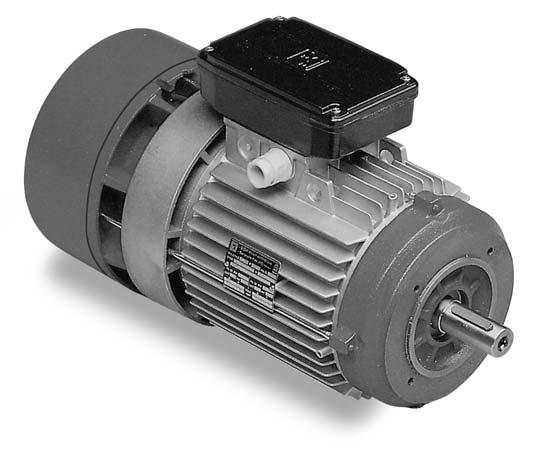
22 GENERAL CHARACTERISTICS BA Series BA series consists of three phase, asynchronous brake motors totally enclosed fan cooled. BA series range starts from 71 up to 22 frame size. The motor brakes in case of power supply failure. The braking action is always secured through a very quick and precise stop assuring a safe and prompt stop in case of unintentional power supply failure. The brake torque remains the same in both directions of rotation and the motor brakes without shaft axial sliding. As a standard the brake is AC 3-phase voltage supply with brake leads connected with motor leads in a single terminal board while on request it is possible to supply the brake separately with a second terminal board or to have a DC brake supply with a built-in rectifier fitted inside the terminal box. The rectifier is provided with over-voltage and radio frequencies emission protection devices. BA series motors tolerate high overloading rate and are capable of withstanding overheating so as to guarantee the best reliability even under tough operating conditions. All MGM series motors have been designed to be controlled by inverters. The motor winding insulation is class F, while class H is available on request. Motor construction type is totally enclosed externally cooled and IP4 enclosure (IP and IP6 available on request). Motors up to 132 frame size are fitted as standard with a hexagonal hole on the shaft at the non drive end to allow manual rotation, even if power is off. All BA series motors are provided as standard with hand brake release screw. BA series brake disc has a large lining surface that allows high brake torque, low disc wear and consequently low maintenance cost. The brake torque can be easily adjustable to the desired value just by screwing some nuts. Thanks to its special construction the brake friction surface is self-ventilated on the motor side, permitting a high brake workload and keeping brake time constant. The brake lining material is asbestos free. BA series motor frame is made of die cast, light metal on motors up to 132 size and the terminal board box, provided with cable glands and plugs, is positioned 1 above the motor support feet. The frame is made of cast iron starting from frame size and the terminal box is located on the right side (drive-end view). Shields and flanges are made of aluminium on motors up to frame size, and of cast iron on motors of frame size and above. As standard feet are frame integrated (they are not simply attached to the frame) on IM B3 mounting (foot mounted) making the motor very sturdy. This feature is very important for those applications where the motor is much stressed during the starts and stops. The brake friction surfaces are made of cast iron as a standard. The brake moving element and the brake coil have a laminated nucleus to reduce electrical losses and to secure a very quick brake intervention. BA series main features are its sturdy construction, quick braking action, constant braking time, high number of permissible start/stop cycles also under severe applications, easily adjustable brake torque, low maintenance costs. 21
23 BA series brake group BA series Air gap adjustment The air gap (24), that is the distance between the two magnetic cores, the brake coil (24) 2 and brake moving element (24), must stay within the value expressed in the chart below. It is not advisable to exceed the expressed value, in order to avoid vibrations of the brake moving element, very loud noise, the brake coil burning or even the whole brake assembly failure. It is advisable to check periodically the air gap because it increases as a consequence of the brake disc wear. In order to set the air gap to the indicated value, you have to loosen the nuts (24) 21 (24) 22 so to move the brake coil (24) 2 towards the brake moving element (24). Once this operation has been settled be sure to tighten the locknuts Frame Size Air Gap Brake torque adjustment 23 The brake torque is proportional to the springs (18) compression, which can be adjusted tightening or loosening the locknuts (). The compression of the three springs must be as even as possible. Once the brake is properly supplied, if the brake coil isn t able to attract the brake moving element with a quick stroke and to keep it attracted without any vibrations, check the air gap adjustment and, if this inconvenience still persists, loosen the locknut () by two threads and try again until the proper functioning is obtained. It is important to consider that some motors can be equipped with 3 springs and some others with 6. (see page 23). Once this operation is completed, check the brake torque to make sure it is set to the desired value. Never set the brake torque to a higher value than the one indicated on the motor nameplate Permissible start frequency under load The technical data tables provide the ideal no-load start frequency (Z0). The permissible start frequency when an external load is applied (Z load) can be found with the following formula: Zload=Z0 K R where Z0 is the table-value for the selected motor and K and R are factors determined by the curves on the side; the factor K is related to the ratio of the moment of inertia of the applied load (Japp) to that of the motor (Jmot) while the factor R is related to the ratio of the resisting torque (Tr) to the starting torque (Ts). This calculation gives an approximative indication only. If the required starting frequency is close to Zload, it is advisable to use a motor equipped with thermal protectors. It is necessary to check the maximum energy dissipation limit of the brake group and the maximum motor RPM in those applications where high moment of inertia is involved. On request is available a special brake disc material capable to withstand very high dissipation energy. Please contact MGM technical staff for additional information. R K 1 0,8 0,6 0,4 0,2 0 1,2 1 0,8 0,6 0,4 0, ,2 0,4 0,6 0,8 1,0 T r / Ts J app /Jmot Brake coil wiring diagram As standard BA series motors are equipped with AC brakes with single terminal board for the brake and the motor while on request it is possible to supply the brake separately. On request DC brakes are available for BA series with the rectifier located inside the terminal box. The rectifier is provided with over-voltage protection devices and with a RFI filter. MGM brake motors equipped with DC brakes can be connected as in diagram A or B according to the needed braking time. MGM motors provided with DC brake coil are connected as in diagram A. The DC brake coil has to be connected according to diagram B to have a reduced brake reaction time. White White Red Grey or Brown Black Brake coil White White Diagram A Red Grey or Brown Black 22 Brake coil Diagram B
24 Brake torque and brake spring compression BA series motors are provided as standard with a brake torque set to - 70% of the maximum admissible brake torque indicated on the nameplate. On request the motor can come already set to a specific brake torque value different from the standard one. The brake torque is shown in the diagrams here below as a function of the brake assembly spring compression. The shown values refer to BA series motors mounted in horizontal position with an AC brake coil. DC brakes have the same trend as AC brakes even if they have lower brake torque, as shown in the table below. The values shown in the diagrams are only indicative as application conditions, brake lining wear and temperature, can affect the real brake torque. Whenever it is necessary to adjust the braking torque to a specific value it is advisable to directly measure the obtained brake torque after each brake torque adjustment. Consider that the motor mounting position influences remarkably the effective braking torque when low brake torque values are involved. Please contact MGM for further information. H BA series Frame size Max AC Brake Torque (Nm): Max DC Brake Torque (Nm): Nm 16 BA 71 Nm BA Nm BA , 1,, 13, 12, 11, mm 0 16, 1,, 13, 12, 11, mm mm BA BA 112 BA 132 Nm Nm Nm mm mm mm Nm 1 BA Nm BA 1- Nm BA ,2 22,8 19,6 18,4 17,2 16 mm Light blue line: 6 springs brake group Blue line: 3 springs brake group Consider that DC brake groups always have 3 springs and 1 Nm max. brake torque mm Light blue line: 6 springs brake group Blue line: 3 springs brake group Consider that DC brake groups always have 3 springs and 1 Nm max. brake torque. 0 39,6,2 36,8 3, ,6 31,2 29,8 mm Light blue line: 6 springs brake group Blue line: 3 springs brake group Consider that DC brake groups always have 3 springs and 2 Nm max. brake torque. 23
25 Technical Data Single Speed Motor Single Winding BA series Motor type 2 poles Power (kw) RPM In (A) 0 V Power factor Cos ϕ Ts/Tn Is/In AC brake In (ma) DC brake In (ma) Z 0 (starts/ hour) Moment of inertia Jx -4 Kgm 2 Max Brake torque (Nm) A-Sound pressure db(a) Weight (Kg) 0 r.p.m. BA 71 A2 BA 71 B2 BA 71 C2 * BA A2 BA B2 BA SA2 BA LA2 BA LA2 BA 112 MB2 BA 112 MC2* BA 132 SA2 BA 132 SB2 BA 132 MA2 * BA 132 MB2 * BA MA2 BA MB2 BA LA2 BA 1 LA2 BA LA2 BA LB poles 0 r.p.m. BA 71 A4 BA 71 B4 BA 71 C4 * BA 71 D4 * BA A4 BA B4 BA C4 * BA SA4 BA LA4 BA LB4 * BA LC4 * BA LA4 BA LB4 BA 112 MB4 BA 112 MC4* BA 132 SB4 BA 132 MA4 BA 132 MB4 * BA 132 MBX4 * BA MA4 BA MB4 BA LA4 BA 1 LA4 BA 1 LB4 BA LB4 BA 22 S4 BA 22 M4 * Non Standard Power
26 Technical Data Single Speed Motor Single Winding Motor type 6 poles Power (kw) RPM In (A) 0 V Power factor Cos ϕ Ts/Tn Is/In AC brake In (ma) DC brake In (ma) Z 0 (starts/ hour) Moment of inertia Jx -4 Kgm 2 Max Brake torque (Nm) A-Sound pressure db(a) 0 r.p.m. Weight (Kg) BA series BA 71 A6 BA 71 B6 BA A6 BA B6 BA SA6 BA LA6 BA LB6* BA LA6 BA LB6 * BA 112 MB6 BA 132 SB6 BA 132 MA6 BA 132 MB6 BA MB6 BA LA6 * BA LB6 BA 1 LB6 BA LA6 BA LB6 BA 22 M poles 0 r.p.m. BA 71 A8 BA 71 B8 BA A8 BA B8 BA SA8 BA LA8 BA LB8* BA LA8 BA LB8 BA 112 MB8 BA 132 SB8 BA 132 MB8 BA MA8 BA MB8 BA LA8 BA 1 LB8 BA LA * Non Standard Power 1. Motor characteristic values reported in the tables refer to continuous duty (S1), 0 Hz frequency, ambient temperature max. C, altitude up to 0 m. above sea level operating condition. 2. DC brake is provided on request only on BA series motors. Brake current consumption values refer to a rated voltage of 3-phase 0V for AC brakes and single-phase 230V for DC brakes. 3. The table shows the sound pressure noise level, measured at one metre range from the motor according to the Acurve (ISO 16). The shown noise levels refer to motor no-load operating condition and should be regarded with a tolerance of ± 3dB. 4. Max brake torque and Z 0 values refer to AC brake. Go to pag. 23 for DC max brake torque values.. The rated torque Tn (Nm) for motors can be calculated as follow: Tn (Nm) = 9, x Pn (W) RPM 2
27 Technical Data Two Speed Motor Single Winding BA series Motor type 2 / 4 poles Power (kw) RPM In (A) 0 V Power factor Cos ϕ Ts/Tn Is/In AC brake In (ma) DC brake In (ma) Z 0 (starts/ hour) Moment of inertia Jx -4 Kgm 2 Max Brake torque (Nm) A-Sound pressure db(a) Weight (Kg) 0 / 0 r.p.m. BAD 71 A2/ BAD 71 B2/ BAD A2/4 BAD B2/4 BAD SB2/ BAD LA2/4 BAD LB2/ BAD LA2/4 BAD LB2/ BAD 112 MB2/4 BAD 132 SB2/4 BAD 132 MA2/4 BAD 132 MB2/4 BAD MA2/4 BAD MB2/4 BAD LA2/4 BAD 1 LA2/4 BAD 1 LB2/4 BAD LB2/
28 Technical Data Two Speed Motor Single Winding Motor type 4 / 8 poles Power (kw) RPM In (A) 0 V Power factor Cos ϕ Ts/Tn Is/In AC brake In (ma) DC brake In (ma) Z 0 (starts/ hour) Moment of inertia Jx -4 Kgm 2 Max Brake torque (Nm) A-Sound pressure db(a) 0 / 0 r.p.m. Weight (Kg) BA series BAD 71 A4/ BAD 71 B4/ BAD 71 C4/8 BAD A4/8 BAD B4/ BAD SA4/8 BAD LB4/ BAD LB4/8 BAD 112 MB4/ BAD 132 SB4/8 BAD 132 MA4/8 BAD 132 MB4/8 BAD MB4/8 BAD LA4/8 BAD 1 LA4/8 BAD 1 LB4/8 BAD LA4/8 BAD LB4/ Motor characteristic values reported in the tables refer to continuous duty (S1), 0 Hz frequency, ambient temperature max. C, altitude up to 0 m. above sea level operating condition. 2. DC brake is provided on request only on BA series motors. Brake current consumption values refer to a rated voltage of 3-phase 0V for AC brakes and single-phase 230V for DC brakes. 3. The table shows the sound pressure noise level, measured at one metre range from the motor according to the Acurve (ISO 16). The shown noise levels refer to motor no-load operating condition and should be regarded with a tolerance of ± 3dB. 4. Max brake torque and Z 0 values refer to AC brake. Go to pag. 23 for DC max brake torque values.. The rated torque Tn (Nm) for motors can be calculated as follow: Tn (Nm) = 9, x Pn (W) RPM 27
29 Technical Data Two Speed Motor Two Windings BA series Motor type 2 / 6 poles Power (kw) RPM In (A) 0 V Power factor Cos ϕ Ts/Tn Is/In AC brake In (ma) DC brake In (ma) Z 0 (starts/ hour) Moment of inertia Jx -4 Kgm 2 Max Brake torque (Nm) A-Sound pressure db(a) Weight (Kg) 0 / 0 r.p.m. BADA 71 B2/ BADA 71 C2/ BADA A2/6 BADA B2/6 BADA SA2/6 BADA LA2/6 BADA LB2/6 BADA LA2/6 BADA LB2/6 BADA 112 MB2/6 BADA 132 SB2/6 BADA 132 MA2/6 BADA 132 MB2/6 BADA MB2/6 BADA LA2/6 BADA 1 LB2/
30 Technical Data Two Speed Motor Two Windings Motor type 2 / 8 poles Power (kw) RPM In (A) 0 V Power factor Cos ϕ Ts/Tn Is/In AC brake In (ma) DC brake In (ma) Z 0 (starts/ hour) Moment of inertia Jx -4 Kgm 2 Max Brake torque (Nm) A-Sound pressure db(a) 0 / 0 r.p.m. Weight (Kg) BA series BADA 71 B2/ BADA 71 C2/ BADA A2/8 BADA B2/8 BADA SB2/8 BADA LA2/8 BADA LB2/8 BADA LA2/8 BADA LB2/8 BADA 112 MB2/8 BADA 132 SB2/8 BADA 132 MA2/8 BADA 132 MB2/8 BADA MB2/8 BADA LA2/8 BADA 1 LB2/8 BADA LB2/ Motor characteristic values reported in the tables refer to continuous duty (S1), 0 Hz frequency, ambient temperature max. C, altitude up to 0 m. above sea level operating condition. 2. DC brake is provided on request only on BA series motors. Brake current consumption values refer to a rated voltage of 3-phase 0V for AC brakes and single-phase 230V for DC brakes. 3. The table shows the sound pressure noise level, measured at one metre range from the motor according to the Acurve (ISO 16). The shown noise levels refer to motor no-load operating condition and should be regarded with a tolerance of ± 3dB. 4. Max brake torque and Z 0 values refer to AC brake. Go to pag. 23 for DC max brake torque values.. The rated torque Tn (Nm) for motors can be calculated as follow: Tn (Nm) = 9, x Pn (W) RPM 29
31 Technical Data Two Speed Motor Two Windings BA series Motor type 4 / 6 poles Power (kw) RPM In (A) 0 V Power factor Cos ϕ Ts/Tn Is/In AC brake In (ma) DC brake In (ma) Z 0 (starts/ hour) Moment of inertia Jx -4 Kgm 2 Max Brake torque (Nm) A-Sound pressure db(a) Weight (Kg) 0 / 0 r.p.m. BADA 71 C4/ BADA A4/6 BADA B4/6 BADA SA4/6 BADA LB4/6 BADA LA4/6 BADA LB4/6 BADA 112 MB4/ BADA 132 SB4/6 BADA 132 MA4/6 BADA 132 MB4/ BADA MB4/ BADA LB4/ BADA 1 LB4/ Motor characteristic values reported in the tables refer to continuous duty (S1), 0 Hz frequency, ambient temperature max. C, altitude up to 0 m. above sea level operating condition. 2. DC brake is provided on request only on BA series motors. Brake current consumption values refer to a rated voltage of 3-phase 0V for AC brakes and single-phase 230V for DC brakes. 3. The table shows the sound pressure noise level, measured at one metre range from the motor according to the Acurve (ISO 16). The shown noise levels refer to motor no-load operating condition and should be regarded with a tolerance of ± 3dB. 4. Max brake torque and Z o values refer to AC brake. Go to pag. 23 for DC max brake torque values.. The rated torque Tn (Nm) for motors can be calculated as follow: Tn (Nm) = 9, x Pn (W) RPM 30
32 Technical Data Two Speed Motor Two Windings Motor type 4 / 12 poles Power (kw) RPM In (A) 0 V Power factor Cos ϕ Ts/Tn Is/In S3 % AC brake In (ma) DC brake In (ma) Z 0 (starts/ hour) Moment of inertia Jx -4 Kgm 2 Max Brake torque (Nm) A-Sound pressure db(a) 0 / 00 r.p.m. Weight (Kg) BA series BADA A4/ BADA B4/ BADA SA4/12 BADA LA4/12 BADA LB4/ BADA LA4/12 BADA LB4/ BADA 112 MB4/12 BADA 132 SA4/ BADA 132 MA4/12 BADA132 MB4/12 BADA MB4/ BADA LB4/ Motor characteristic values reported in the tables refer to continuous duty (S1), 0 Hz frequency, ambient temperature max. C, altitude up to 0 m. above sea level operating condition. 2. DC brake is provided on request only on BA series motors. Brake current consumption values refer to a rated voltage of 3-phase 0V for AC brakes and single-phase 230V for DC brakes. 3. The table shows the sound pressure noise level, measured at one metre range from the motor according to the Acurve (ISO 16). The shown noise levels refer to motor no-load operating condition and should be regarded with a tolerance of ± 3dB. 4. Max brake torque and Z o values refer to AC brake. Go to pag. 23 for DC max brake torque values.. The rated torque Tn (Nm) for motors can be calculated as follow: Tn (Nm) = 9, x Pn (W) RPM 31
33 Technical Data Two Speed Motor Two Windings BA series Motor type 2 / 12 poles Power (kw) RPM In (A) 0 V Power factor Cos ϕ Ts/Tn Is/In S3 % AC brake In (ma) DC brake In (ma) Z 0 (starts/ hour) Moment of inertia Jx -4 Kgm 2 Max Brake torque (Nm) A-Sound pressure db(a) Weight (Kg) 0 / 00 r.p.m. BADA B2/ BADA SB2/ BADA LA2/ BADA LB2/ BADA 112 MB2/ BADA 132 SB2/ BADA 132 MA2/ BADA 132 MB2/ BADA MB2/ BADA LA2/ BADA 1 LB2/ Hoisting motors 4/16 poles Motor Type Power(kW) RPM Service duty S4 (% 4 pole 2% 16 poles) BAPKDA 132 MA4/16 BAPKDA 132 MB4/16 BAPKDA MA4/16 BAPKDA MB4/16 BAPKDA LB4/16 BAPKDA 1 LA4/16 BAPKDA LB4/16 BAPKDA 22 S4/16 BAPKDA 22 M4/16 / 0.7 / 1.1. / /.0 / 13.2 / 1 / 19.0 / / / 30 / 30 / 33 / 330 / 330 / 30 / / 3 70 / 3 In 0 V (A) 7.3 /.1.8 / / 16.2 / / / / / 2.3 / 34.7 Ibrake (ma) AC 0 / 3 r.p.m Motor characteristic values reported in the tables refer to continuous duty (S1), 0 Hz frequency, ambient temperature max. C, altitude up to 0 m. above sea level operating condition. 2. DC brake is provided on request only on BA series motors. Brake current consumption values refer to a rated voltage of 3-phase 0V for AC brakes and single-phase 230V for DC brakes. 3. The table shows the sound pressure noise level, measured at one metre range from the motor according to the Acurve (ISO 16). The shown noise levels refer to motor no-load operating condition and should be regarded with a tolerance of ± 3dB. 4. Max brake torque and Z o values refer to AC brake. Go to pag. 23 for DC max brake torque values.. The rated torque Tn (Nm) for motors can be calculated as follow: Tn (Nm) = 9, x Pn (W) RPM 32
34 Brake Linings Wear, Starting and Braking time brake linings wear Brake linings wear is mainly affected by the environmental conditions in which the motor operates, by the frequency of starts, by the energy dissipated at each stop and by the torque provided by the brake. The lining temperature rises with the braking frequency and with the moment of inertia applied to the shaft. When the lining temperature raises, the lining wear increases and consequently the braking time is longer. BA series motors are designed to have continuous cooling of the braking surfaces so as to reduce brake disc wear to have a shorter braking time. The life cycle of the brake linings can be roughly expressed by the number of brake interventions and can be approximately calculated as follows: n = Wtot / Wb where Wb (J) is the work done during each braking action and Wtot (J) is obtained from the table for each type of brake motor. However, it is necessary to check the brake disc wear periodically to replace the brake disc before it is completely worn. If you want to estimate the interval between two successive air gap adjustment in a specific application, note that the brake linings wear is greater than usual during the run-in (a few thousands stops). On PV series brake motors Wtot shown in the table have to be multiplied by 0. and the moment of inertia have to be calculated considering the presence of the fly-wheel. The indicative number of AC brake stops NintAC between two successive air gap adjustments on a BA motor is given by the following formula: NintAC = ErBA / Wb while the NintDC for DC brake motors is given by : NintDC = NintAC 0.6 BA series Wtot (MJ) ErBA (MJ) The indicative number of DC brake stops NintBM between two successive air gap adjustments on a BM motor is given by the following formula: ErBM values are shown at pag. 39 (BM section). An indicative braking time tf (s) can be calculated as follows: Motor Type BA 71-- BA -112 BA 132- BA 1- BA 22 AC Brake DC Brake (Standard) 8 NintBM = ErBM / Wb DC Brake (Quick) ϕ s = ta n 19.1 Starting and braking time Starting current for an asynchronous motor is always much higher than the nominal current. When the starting time is excessively long, there are electromechanical disturbances and higher temperatures on winding, damaging the motor. For information on maximum starting time allowed for each type of motor, please contact MGM. An indicative value for starting time ts (expressed in seconds) and the angle of rotation ϕs (expressed in radians) can be obtained as follows: ts = Where Japp (Kgm 2 ) is the moment of inertia referred to the motor shaft, Mload (Nm) is the opposing torque to the motor, Jmot (Kgm 2 ) is the moment of inertia of the motor, n (RPM is the rated motor RPM), T is the average starting torque, T=(0,8 0,9)Ts (see the technical data table for Jmot, n and Ts of the selected motor). Brake electrical reaction time tb (ms) (Jmot + Japp) n 9. (T - Tload) tf = Jtot n 9. (Tb ±Tload) The reported tb times are valid only if the motor is connected with the brake. In case the brake is supplied separately, the tb time has to be cut by 30 0%. This calculation gives an approximative indication. Please contact MGM for further information. + tb 0 Where: Jtot total moment of inertia at the motor shaft (Kgm 2 ) n motor RPM (min -1 ) Tb brake torque (Nm) Tload resisting load torque (Nm) with + sign if matches the brake torque, or sign if opposite. tb brake electrical reaction time (ms) 33
35 BA series dimensions BA series Dimension A B C D* d E* Fa Fb f g H h I K L L1 Ma Mb Na Nb Oa Ob Pa Pb Q QBAF/BAPV R R1 S V W W1 Y Z Z1 BA 71 BA BA S BA L BA L BA 112 M BA 132 S BA 132 M BA M BA L BA 1 L BA L BA 22 S BA 22 M M M6 M8 M8 M M M12 M12 M16 M16 M16 M16 M16 M M6 M6 M8 M8 M8 M8 M M , 98, 98, 98, * 22S-22M 2 poles D=, E=1 Notes: QBAF is the Q dimension for BAF series QBAPV is the Q dimension for BAPV series Cable glands are M on size 71 up to M 2 on size up to 112 M 32 on size 132 PG 29 on size up to M 0 on size 22 34
36 BA series dimensions B3 (Foot Mounting) BA series B (Flange mounting) B (Face Mounting) Size /1//22 B3 (Foot Mounting) Double Terminal Board Box 3

37 BM series B B B3 36
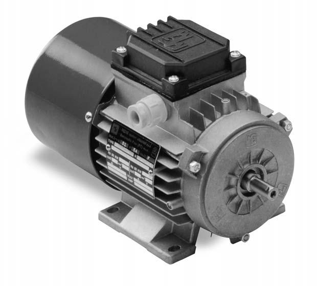
38 General Characteristics BM series BM series consists of three phase, asynchronous brake motors totally enclosed fan cooled. BM series range starts from 6 up to frame size. The motor brakes in case of power supply failure. The brake torque remains the same in both directions of rotation and the motor brakes without shaft axial sliding. As standard the brake is DC voltage supply with a built-in rectifier fitted inside the terminal box. The rectifier is provided with over-voltage and radio frequencies emission protection devices. Two different types of rectifier wiring can be chosen according to two different brake intervention time. BM series is designed in order to have a braking action as quiet as possible. BM series motors tolerate a high overloading rate and are capable to withstand overheating so to guarantee best reliability also under tough operating conditions. All MGM motors have been designed to be controlled by inverters. The motor winding insulation is class F, while class H is available on request. Motor construction type is totally enclosed externally cooled and IP4 enclosure (IP and IP6 available on request). Motors up to 132 frame size are fitted as standard with a hexagonal hole on the shaft at non drive end to allow manual rotation, even if power is off. On request, BM series motors can be provided with side manual brake release lever. The brake disc lining material is asbestos free and the lining mixture is formulated to have a high friction coefficient and long lasting. BM series motor frame is made of die cast, light metal on motors up to 132 size and the terminal board box, provided with cable glands and plugs, is positioned 1 above the motor support feet. The frame is made of cast iron starting from frame size and the terminal box is located on the right side (drive-end view). Shields and flanges are made of aluminium on motors up to frame size, and of cast iron on motors of frame size and above. On IM B3 mounting (foot mounted) feet are frame integrated (they are not simply attached to the frame) as standard and it makes the motor very sturdy. This feature is very important for those applications where the motor is much stressed during the starts and stops. BM series main features are the low braking noise, gradual acceleration during the motor start and stop and reduced overall dimensions. 37
39 BM series brake group BM series General description BM series motors are equipped with DC brake coil. DC brake coil is supplied through a rectifier located in the terminal box (standard voltage supply is 230V 0/ Hz). The rectifier is provided with over-voltage and radio frequencies emission protection devices. The brake torque remains the same in both directions of rotation and the motor brakes without shaft axial sliding. Brake torque can be set loosening or tightening the adjustable springs (78) where available or removing the central springs or replacing the fixed ones. Never set the brake torque to a higher value than the one indicated on the motor nameplate. BM series motors are fitted as a standard with a hexagonal hole on the shaft at non drive end to allow manual rotation. On request BM series motors can be provided with brake release return lever located on the motor side. Air gap adjustment The air gap (), that is the distance between the two magnetic cores, the brake coil () and brake moving element (), 74 must stay within the value expressed in the chart below. It is advisable to check periodically the air gap because it increases as a consequence of the brake disc wear. In order to restore the air gap within the proper value release the connecting screws (), 77 move the brake coil () towards the brake moving element () 74 operating on the fixing screws (). 79 Once this operation has been settled be sure to tighten clockwise the connecting screws () 77 so to fasten again the brake coil Frame Size Min Air Gap[mm] Max Air Gap[mm] /71 0,2 0,6 0,2 0,7 0,3 0,8 0,3 0, ,3 1, ,4 1,1 0,4 1, Permissible start frequency with load The technical data tables provide the ideal no-load start frequency (Z0). The permissible start frequency when an external load is applied (Z load) can be calculated as follows: Zload=Z0 K R R 1 K 1,2 0,8 1 0,6 0,4 0,8 0,6 0,4 0,2 0, ,2 0,4 0,6 0,8 1,0 T r / T s where Z0 is the table-value for the selected motor and K and R are factors determined by the curves on the side; the factor K refers to the calculated ratio between the moment of inertia of the applied load (Japp) and that of the motor (Jmot) while the factor R is the calculated ratio between the resisting torque (Tr) and the starting torque (Ts). This calculation gives an approximative indication only. If the required starting frequency is close to Zload, it is advisable to use a motor equipped with thermal protectors. It is necessary to check the maximum energy dissipation limit of the brake group and the maximum motor RPM on those application where high moment of inertia is involved. Please contact MGM technical staff for additional information J app /Jmot
40 BM series brake group Rectifiers wiring diagram BM series brake motors can be connect as diagram A or B according to the needed braking time. MGM motors are always provided with DC brake coil connected as diagram A. The DC brake coil has to be connected according to diagram B in order to have a quicker brake action. Here below brake intervention times and brake release time are provided. BM series White White Red Grey or Brown Black White White Red Grey or Brown Black Brake coil Brake coil Diagram A Diagram B The chart here below describes the trend of the braking torque as a function of time, during the start (on the left) and stop (on the right). The table below also show times for each type of motor and the values of Er (MJ) to calculate the number of braking actions between two consecutive air gap adjustment. (See page 33). Tb Tbn t1 0,1 Mbn t21 t22 0,9 Mbn t Tb Brake Torque Tbn Nominal Brake Torque t1 Switch-on time t21 Delay Time t22 Rise Time t2 Reaction Time t2 Frame size t1 (ms) t21 quick (ms) t22 quick (ms) t2 quick (ms) t21 standard (ms) t22 standard (ms) t2 standard (ms) ErBM (MJ) *Note: The air gap can t be restored on BM6 motors. The brake disc have to be replaced when the air gap exceed the stated value * Jtot n t2 The braking time tf (s) can be calculated as follows: tf = + 9. (Tb ±Tload) 0 Where: Jtot total moment of inertia at the motor shaft (Kgm 2 ) n motor RPM (min -1 ) Tb brake torque (Nm) Tload resisting load torque (Nm) with + sign if matches the brake torque, or sign if opposite t2 brake electrical reaction time (ms) This calculation gives an approximative indication. Please contact MGM staff for more information. Braking Time 39
41 Technical Data Single Speed Motor Single Winding BM series Motor type 2 Poles BM 6 A2 BM 6 B2 BM A2 BM B2 BM C2* BM 71 A2 BM 71 B2 BM 71 C2* BM A2 BM B2 BM SA2 BM LA2 BM LA2 BM 112 MB2 BM 112 MC2* BM 132 SA2 BM 132 SB2 BM 132 MA2* BM 132 MB2* BM MA2 BM MB2 BM LA2 Power (kw) RPM In (A) 0 V Power factor Cos ϕ Ts/Tn Is/In DC brake In (ma) Z 0 (starts/ hour) Moment of inertia Jx -4 Kgm Max Brake torque (Nm) 2 2 A-Sound pressure db(a) Weight (Kg) 0 RPM Poles 0 RPM BM 6 A4 BM 6 B4* BM 6 C4 BM A4 BM B4 BM C4* BM D4* BM 71 A4 BM 71 B4 BM 71 C4* BM 71 D4* BM A4 BM B4 BM C4* BM SA4 BM LA4 BM LB4* BM LC4* BM LA4 BM LB4 BM 112 MB4 BM 112 MC4* BM 132 SB4 BM 132 MA4 BM 132 MB4* BM 132 MBX4* BM MA4 BM MB4 BM LA * Non Standard Power
42 Technical Data Single Speed Motor Single Winding Motor type 6 Poles BM 6 B6 BM C6 BM D6 BM 71 A6 BM 71 B6 BM A6 BM B6 BM SA6 BM LA6 BM LB6* BM LA6 BM LB6 BM 112 MB6 BM 132 SB6 BM 132 MA6 BM 132 MB6 BM MB6 BM LA6* BM LB6 Power (kw) RPM In (A) 0 V Power factor Cos ϕ Ts/Tn 1.9 Is/In DC brake In (ma) Z 0 (starts/ hour) Moment of inertia Jx -4 Kgm Max Brake torque (Nm) 2 A-Sound pressure db(a) 0 RPM Weight (Kg) BM series 8 Poles 0 RPM BM D8 BM 71 A8 BM 71 B8 BM A8 BM B8 BM SA8 BM LA8 BM LB8* BM LA8 BM LB8 BM 112 MB8 BM 132 SB8 BM 132 MB8 BM MA8 BM MB8 BM LA * Non Standard Power 1. Motor characteristic values reported in the tables refer to continuous duty (S1), 0 Hz frequency, ambient temperature max. C, altitude up to 0 m. above sea level operating condition. 2. The expressed brake torque is the max admissible one. Brake current consumption values refer to a rated voltage of 230V AC single-phase. 3. The table shows the sound pressure noise level, measured at one metre range from the motor according to the Acurve (ISO 16). The shown noise levels refer to motor no-load operating condition and should be regarded with a tolerance of ± 3dB. 4. The rated torque Tn (Nm) for motors can be calculated as follow: Tn (Nm) = 9, x Pn (W) RPM 41
43 Technical Data Two Speed Motor Single Winding BM series Motor type 2 / 4 Poles Power (kw) RPM In (A) 0 V Power factor Cos ϕ Ts/Tn Is/In DC brake In (ma) Z 0 (starts/ hour) Moment of inertia Jx -4 Kgm 2 Max Brake torque (Nm) A-Sound pressure db(a) Weight (Kg) 0 / 0 RPM BMD B2/4 BMD C2/4 BMD 71 A2/4 BMD 71 B2/4 BMD A2/4 BMD B2/4 BMD SB2/4 BMD LA2/4 BMD LB2/4 BMD LA2/4 BMD LB2/4 BMD 112 MB2/4 BMD 132 SB2/4 BMD 132 MA2/4 BMD 132 MB2/4 BMD MA2/4 BMD MB2/4 BMD LA2/ / 8 Poles 0 / 0 RPM BMD 71 A4/8 BMD 71 B4/8 BMD 71 C4/8 BMD A4/8 BMD B4/8 BMD SA4/8 BMD LB4/8 BMD LB4/8 BMD 112 MB4/8 BMD 132 SB4/8 BMD 132 MA4/8 BMD 132 MB4/8 BMD MB4/8 BMD LA4/
44 Technical Data Two Speed Motor Two Windings Motor type 2 / 6 Poles Power (kw) RPM In (A) 0 V Power factor Cos ϕ Ts/Tn Is/In DC brake In (ma) Z 0 (starts/ hour) Moment of inertia Jx -4 Kgm 2 Max Brake torque (Nm) A-Sound pressure db(a) 0/0 RPM Weight (Kg) BM series BMDA 71 B2/6 BMDA 71 C2/6 BMDA A2/6 BMDA B2/6 BMDA SA2/6 BMDA LA2/6 BMDA LB2/6 BMDA LA2/6 BMDA LB2/6 BMDA 112 MB2/6 BMDA 132 SB2/6 BMDA 132 MA2/6 BMDA 132 MB2/6 BMDA MB2/6 BMDA LA2/ / 8 Poles /0 RPM BMDA C2/8 BMDA 71 B2/8 BMDA 71 C2/8 BMDA A2/8 BMDA B2/8 BMDA SB2/8 BMDA LA2/8 BMDA LB2/8 BMDA LA2/8 BMDA LB2/8 BMDA 112 MB2/8 BMDA 132 SB2/8 BMDA 132 MA2/8 BMDA 132MB2/8 BMDA MB2/8 BMDA LA2/ Motor characteristic values reported in the tables refer to continuous duty (S1), 0 Hz frequency, ambient temperature max. C, altitude up to 0 m. above sea level operating condition. 2. The expressed brake torque is the max admissible one. Brake current consumption values refer to a rated voltage of 230V AC single-phase. 3. The table shows the sound pressure noise level, measured at one metre range from the motor according to the Acurve (ISO 16). The shown noise levels refer to motor no-load operating condition and should be regarded with a tolerance of ± 3dB. 4. The rated torque Tn (Nm) for motors can be calculated as follow: Tn (Nm) = 9, x Pn (W) RPM 43
45 Technical Data Two Speed Motor Two Windings BM series Motor type 4 / 6 Poles Power (kw) RPM In (A) 0 V Power factor Cos ϕ Ts/Tn Is/In DC brake In (ma) Z 0 (starts/ hour) Moment of inertia Jx -4 Kgm 2 Max Brake torque (Nm) A-Sound pressure db(a) Weight (Kg) 0 / 0 RPM BMDA 71 C4/6 BMDA A4/6 BMDA B4/6 BMDA SA4/6 BMDA LB4/6 BMDA LA4/6 BMDA LB4/6 BMDA 112 MB4/6 BMDA 132 SB4/6 BMDA 132 MA4/6 BMDA 132 MB4/6 BMDA MB4/6 BMDA LB4/ / 12 Poles S3 % 0 / 00 RPM BMDA A4/12 BMDA B4/12 BMDA SA4/12 BMDA LA4/12 BMDA LB4/12 BMDA LA4/12 BMDA LB4/12 BMDA 112 MB4/12 BMDA 132 SA4/12 BMDA 132 MA4/12 BMDA 132 MB4/12 BMDA MB4/12 BMDA LB4/ Motor characteristic values reported in the tables refer to continuous duty (S1), 0 Hz frequency, ambient temperature max. C, altitude up to 0 m. above sea level operating condition. 2. The expressed brake torque is the max admissible one. Brake current consumption values refer to a rated voltage of 230V AC single-phase. 3. The table shows the sound pressure noise level, measured at one metre range from the motor according to the Acurve (ISO 16). The shown noise levels refer to motor no-load operating condition and should be regarded with a tolerance of ± 3dB. 4. The rated torque Tn (Nm) for motors can be calculated as follow: Tn (Nm) = 9, x Pn (W) RPM 44
46 BM series dimension Type 6 71 S L L 112M 132S 132M M L B3 (Foot Mounting) A B C D d E Fa Fb f g H h I K L M3 6.6 M M M M M M6 11. M M M M M M M M M M12 M M12 M M M B (Flange Mounting) L Ma B (Face Mounting) Mb Na Nb Oa Ob Pa Pb Q R R1 S V W W 1 Y , Double Terminal Board Box Z Z Size B3 (Foot Mounting) BM series Shaft End Note Cable glands are M 16 on size 6 up to M on size 71 up to M 2 on size up to 112 M 32 on size 132 PG 29 on size
47 Traverse motors with progressive start and stop PV series A few problems such as swinging of suspended loads, slipping of trolley wheel on rails, the breakage of some delicate mechanisms can occur on traverse applications. All these problems can be solved using progressive start/stop systems such as clutches, hydraulic couplings, slip-ring motors or soft start devices. Experience has shown that progressive start/stop brake motor is a valid alternative to all the other adducted systems. Traverse motors are provided with a flywheel whose dimension and weight are calculated in order to have an adequate moment of inertia. The ratio of rated torque to starting (locked rotor) torque is calculated in order to achieve the best progressive performance. The flywheel accumulates energy during the start and gives it back during the stop resulting in a progressive change of the rotating speed. PV series motors don t need adjustments with load change or any special maintenance and the progressive action is directly proportional to the load increase. During the planning stage it is necessary to carefully choose the proper motor power as an insufficient power could cause overheating while a too powerful motor could reduce the effect of the flywheel progression. PV series motors are designed with a special rotor to reduce the starting (locked rotor) current so to allow heavy start/stop duty cycle, even if the starting period doesn t have to be too long in order to avoid overheating. BAPV series motors provide a reduced brake torque, resulting in a really progressive braking action. The brake torque of BAPV motors is about the half of the corresponding BA standard brake motors while BM and BMPV series motors have the same brake torque. BAPV motors are fitted with a flywheel strongly secured to the motor shaft while BMPV motors are fitted with cast-iron cooling fan replacing the thermoplastic one. PV series motors are available with the following features or option: - Separate brake supply, - Manual brake release, - Suitable for mounting in any position (vertical, horizontal, etc.) - Two speeds The table below shows the moment of inertia increase (Kgm2) for BAPV and BMPV series. Motor Type BAPV BMPV The total moment of inertia of a chosen motor is the moment of inertia of a standard brake motor (see motors technical data) plus the flywheel moment of inertia (shown in table above). Example: moment of inertia of BAPV 71 B4 = moment of inertia of BA 71 B4 + flywheel type BAPV 71 B4 moment of inertia = = Kgm 2. The table below shows the maximum brake torque (Nm) for BMPV with DC brake and BAPV motors with AC brake or DC brake: Motor Type BMPV BAPV - A.C. BAPV - D.C , 9 7,

48 BAPV series BMPV series
49 Hoisting Motors BAPK series BAPK series motors are available starting from up to 22 frame size. Powers and poles are the same as the BA series motors (see BA technical data). BAPK series motors have the same motor construction as BA series motors but present some special parts. Single and most-off the two speed BAPK motors are fitted with a special rotor (P rotor) that increases the starting (locked rotor) torque by % about and that reduces the starting (locked rotor) current by % about. The brake disc nucleus and hub are made of steel (see k brake disc section). AC brake coil is provided to secure a fast brake intervention. Feet are frame integrated on B3 mounting (foot mounted) and not simply attached to the frame. This feature guarantee best reliability of brake motors for hoist application. Shields and flanges are made of cast iron. Frame is made of aluminium from up to 132 frame size (132 cast iron frame is available on request) while it is made of cast iron starting from frame size. Dimensions are the same as the BA series (dimensions sheet pag. 34). To purchase BAPK series motors the writing BAPK have to be clearly stated in the order (i.e. BAPK 112 MB4/16). K Brake Disc Nucleus and hub of K brake disc are made of steel that means a higher sturdiness and moment of inertia. The K brake disc is provided as standard on motors starting from up to 22 frame size while it s available on request on motors from up to 132 frame size. BA standard brake motors up to 132 frame size are made of a special aluminium/thermoplastic material. K brake disc is strongly recommended for hoisting application or under high environment temperature (0 C or above). K brake disc have a shorter lasting than standard brake disc as a consequence of the increased moment of inertia therefore it s advisable to use standard brake disc on heavy start/stop duty cycle application where the K disc is not necessary to purchase motors with K brake disc, the writing BAK have to the clearly stated in the order (i.e. BAK 112 MB4). Premium Brake Torque Motors BAF series BAF series BAF series motors are brake discs motors providing a very high brake torque. BAF series motors are particularly suitable for those applications where it s needed to keep the motor locked up also under a very high turning moment. BAF series motors are provided with AC brake. BAF motors are available starting from up to 22 frame size. The table below shows the BAF series brake torque values. Motor Type BAF BAF 112 BAF 132 BAF BAF 1 BAF BAF 22 Brake Torque Max (Nm)
50 Forced Cooling Motors AC electric motors operating in non standard conditions (low frequency inverter duty, long overcharge periods, heavy duty cycles) could need additional cooling servo-fan. BASV series motors with forced cooling are provided with two additional cooling servo-fans fixed on the motor frame. This cooling system is an MGM patent. SV series motors have the following features: 1. The standard self cooling fan inside the motor is kept additionally to the two cooling servo-fans. 2. The whole heating surface is increased as the fan fixing system is itself a heat dissipation element additionally to the existing fins on the frame. 3. Low noise level. 4. No additional motor length compared to the standard one.. Manual brake release with manual rotation. 6. Uniform winding cooling along the whole motor length. 7. The brake friction surface is cooled on the motor side. SV series Where the forced cooling is used to limit the operating temperature in heavy start/stop duty application, it should be noted that the efficiency of the forced cooling increases with the number of poles of the motor. It s hard to estimate the amount of hot air removed by the forced cooling fans but it can be roughly said that it is the same as the air removed by the standard servo-fan of a 4 pole motor operating at 0 Hz. It is advisable to use thermal protectors in heavy operating conditions. The table below shows technical details of fans supplied at 230V single-phase. Motor can be supplied both at 0Hz or Hz. On request forced cooling fans can be provided with different voltage supply. BMAV series motors with forced cooling are provided with single axial servo-fan replacing the standard motor self cooling fan. Motor Type Dim X Dim Y Dim L Volt Amp m 3 /h db (A) BASV 71 BASV BASV BASV BASV 112 BASV 132 BASV BASV 1 BASV BASV x0.1 2x0.1 2x0.12 2x0.12 2x0.12 2x0.12 2x0.30 2x0.30 2x0.30 2x BASV Series 49
51 Built-in Encoder Motors Technical Characterisitic BAE-BMEAV series Built-in Encoder Motors Motors with built-in encoder represent a revolutionary component in the automation field providing OEM and end user with new opportunities and with notable economic advantages due to its user-friendly design. The range of three phase asynchronous motors with built-in encoder has been designed specifically to offer to the end user a comprehensive choice of an already widely tested motor with superior quality. MGM motors with integrated encoder can be divided in two series of brake motors (BAE/BMEAV) and two series of standard motors (SAE/SMEAV) without brake. The power range starts from 0.06 kw up to kw (frame size from 6 up to 22). The unit consists of a three phase asynchronous high efficiency motor with a low moment of inertia and with the encoder located at the Non-Drive side. Motors are designed to be suitable for inverter use. Precise dynamic balancing together with an accurate motor insulation system are adopted in order to withstand electrical and mechanical stress. The mechanical coupling is the same standard motors (special shaft and flange are available on request), wirings are very simple to be made: power and electrical signal duly separated. MGM motors with integrated encoder can be supplied in conformity with requirements of standards UL 4 Electric motors and CSA C 2 No. -9 Motors and generators (ccsaus approval). MGM provides 4 different motor series suitable to meet accurately all possible drives challenges. BAE series: asynchronous three phase fan cooled brake motors with built-in encoder and frame size from 71 up to 22. The encoder is located at the Non-Drive side in a safe place protected by a well closed cover. Forced ventilation is available on request. The motor is provided as standard with separate brake supply. The brake coil is AC as standard, while DC is available on request. BMEAV series: asynchronous three phase brake motors with DC brake with axial forced ventilation, built-in encoder and frame size from up to. The encoder is located at the non drive end side between the brake and the servo fan. The motor is supplied as standard with separate brake supply. Side manual return brake release available on request. SAE series: asynchronous three phase fan cooled motors with built-in encoder and shaft heights between 71 mm and 22 mm. The encoder is located at the non drive end side in a safe place protected by a well closed cover. On request it s available with forced ventilation. SMEAV series: asynchronous three phase motors equipped with forced ventilation with built-in encoder and frame size from 71 up to 22. The encoder is located at the non drive end side inside the fan cover between the motor and the forced cooling fan. Encoder The encoder is a rotational transducer to convert an angular movement into a series of electrical digital impulses. Usually the encoders used on MGM motors are based on the working principle of the angular movement transduction. The reading system is based on the rotation of a radial graduated disc formed by opaque windows alternated with transparent ones. This system is all illuminated in perpendicular way by an infrared light source, so the light projects the disc image on the surface, which is covered by a grating, having the same step as the disc. The receiver converts the light variations occurring with the disc shifting into their corresponding electrical variations. Incremental encoder position is determined by the number of impulses from the zero index; Absolute encoder position is determined by an output position code which is univocally determined within each encoder revolution. To exactly identify the incremental encoder, the fallowing characteristics have to be indicated: - Resolution - Impulse of Zero - Power supply - Electronic output configuration To identify absolute encoders are additionally required: - Code - Single turn or Multi turn The output cable is provided as standard without connector (floating cable). On request a connector can be supplied. Please contact MGM for further information. Cooling Motor cooling is usually assigned to the motor self-cooling fan (BAE and SAE series). BMEAV and SMEAV series are forced cooling motors. On request the BMEAV and SMEAV series motors can be provided without forced ventilation (BME and SME series self-cooled motors). On request BAE and SAE series motors can be provided with radial forced ventilation (BAESV and SAESV series) with two servo fans fixed on the frame, additionally to the standard self cooling fan located at the Non-Drive and side. 0
52 BAE Series Dimensions Dimension 71 S L L 112M 132S 132M M L 1L L 22S 22M B3 (Foot Mounting) A B C D* d M M6 M8 M8 M M M12 M12 M16 M16 M16 M16 M16 M16 E* Fa 9, 11, 11, 11, , 18, Fb M6 M6 M8 M8 M8 M8 M M B (Flange mounting) f g H h , , I ,, 1 18, K, L , Ma Mb B (Face Mounting) Na Nb Oa Ob Pa Pb , 2, 130 3, , , , , , , Q q R1 S Size /1//22 B3 (Foot Mounting) V W 8 9,,, 12, 13, W , 321, Y Y1 Z BAE series * 22S-22M 2 poles D=, E=1 Double Terminal Board Box 1
53 BMEAV Series Dimensions BMEAV Series Dimension A S 0 L 0 L 112M 132S M 216 M 24 L 24 B3 (Foot Mounting) B C D d M4 M M6 M8 M8 M M M12 M12 M16 M16 E Fa 9, 9, 11, 11, 11, Fb f M 4 M6 M6 6 M8 8 M8 8 M8 8 M8 8 M M B (Flange Mounting) g 8, 11 1, H h I ,, K,, L Ma Mb B (Face Mounting) Na Nb Oa 3 3, 3, 3, 3, Ob 2, 2, , 3, 3, 3, Pa Pb Q R S Double Terminal Board Box V 7 8 9,,, 12, 13, W 1 1 W Y , Z Shaft End 2
54 Built-in inverter motors Built-in inverter motors consist of three-phase asynchronous electric motors with integrated frequency inverter. Power range is between 0,37 kw and 1,0 kw while the motor frame is from 71 up to. The unit is made up of a high-efficiency 3-phase asynchronous electric motor and a compact frequency inverter placed at the non-drive motor end. The basic construction is closed, fan cooled and IP enclosure duty. Built-in inverter motor is able to properly run also under heavy overload conditions thanks to a high thermal reserve; the insulating materials are class F. The frame is made of aluminium alloy up to 132 frame size and of cast iron for above sizes. Shields and flanges are made of aluminium up to frame size and of cast iron up to frame size. The inverter housing is isolated from the motor in order to avoid heat transmission (patented system); the inverter heat sink is self-ventilated. The frequency converter provided is one of the most advanced in design concept as well as used components; control can be chosen between V/F type (frequency voltage control) or SLV type (Sensorless Vector Control). Built-in inverter motors are easy to be programmed using only three buttons. Some functions, which automatically set parameters (acceleration/deceleration times, V/f ratio etc.), make the programming easier. On request, motor can be arranged for main Bus fields (Profibus, Interbus-S, Device-Net, etc.). Built-in inverter motors are designed to be real built-in frequency converter motors and not just as a simple assembly of a standard motor with an inverter. The wiring connection is definitely simple to be made. All the adducted features make the built-in inverter motor series high performance with strong structure. General Characteristics Benefit and Applications Built-in inverter motors represent an innovation in the automation field and they give manufacturers, automation designers and machinery users new opportunities and great economical advantages. The ease of installation, the simple structure and the costeffectiveness of the system are pointed out as follows. Overall dimensions are extremely reduced; the couplings are the same as those of a standard motor (special flanges and shafts can be supplied on request); Protection class is IP as standard (IP 6 is available on request); Electrical connections are extremely simplified; power and control are totally separated and placed on different terminal boards; On request, motor can be equipped with built-in EMI filter (class A or B) in the way to avoid an external filter application; the motor connection can be carried out through normal power supply cables, as shielded cables are no longer necessary in order to comply with EMC regulations; SMI series motor can immediately replace a mechanical speed variator, offering more advantages; The system performance is very high in every operating condition; Unit switchboard on which SMI motor is installed can be removed or reduced as the inverter has no longer to be housed. SMI motor represents the solution to the actual needs related to automation systems where actuating and surveying devices can find more places on unit board so to reduce the panel overall dimensions and the wiring costs. 3
55 Built-in inverter motors Technical Specifications Main Specifications Power range kw (single-phase) kw (three-phase) Supply voltage 1x-2 V 0/ (single phase) 3x3-4 V 0/ (three-phase) Protection class (enclosure duty) IP (IP6 on request) Mounting IM B3-foot mount, IM B-flange mount, IM B-face mount (shaft/flange reduced/increased on request) Type of control V/F frequency voltage control (letter x behind the motor plate) SLV sensorless vector control (letter V behind the motor plate) Speed adjustment range 3- Hz for version X (frequency voltage control) 1- for version V (vector control without sensor) Analog input 0- V D.C. 4- ma Digital input programmable with functions (for versions X) 6 programmable with 19 functions (for versions V) Digital output - 1 programmable relay - only alarm (exchange contact V AC A) version X - 1 programmable relay with 6 functions version V - 2 outputs with programmable transistors with 6 functions (open collector 27 V 0 ma) Serial interface RS 422 as standard for parameters loading/unloading RS 48 multidrop for automation by external module Protection functions Over-current, over-voltage, low voltage, overloading, exceeding operation temperature, CPU error, starting phase earthed protection Options Forced cooling It allows a wider application of built-in inverter motors. It can be required at the time of the purchase or in case installed afterwards, buying the proper kit. Thermal protection devices they can be inserted into the motor and controlled by the inverter logic External potentiometer it can be built-in (allowing the speed regulation directly on the motor) Remote control panel SMI motor can be also controlled through a remote keyboard. The keyboard is equipped with parameter copy function Built-in EMI filters Class A (industrial application) Class B (residential application) Braking dynamic resistance it can be fitted in the version with vector control Field bus it can be arranged for the main commercial buses (Profilbus, Interbus-S, Device Net, etc.) 4

56 General Characteristics BMBM Series BMBM series consist of three phase AC brake motors with twin DC brakes working independently of each other, starting from 71 up to frame sizes and power range from 0.18 kw up to 37 kw. BMBM series main feature is a very high reliability in those lifting applications where there are high demands of safety and quiet. For these reasons BMBM series motors are particularly suitable to be used for TV-cine studios and theatre s stages. The motor brakes in case of power supply failure. The braking action is always secured through a very quick and precise stop assuring a safe and a prompt stop in case of unintentional power supply failure. The brake components and assembly are designed with special features to be noiseless during stops, granting the high ratings of EN81. The manual brake release is made up of two levers (one for each brake) so to avoid unwanted starts. It s possible to release the brake just using one hand. The two brakes are supplied through independent rectifiers which are positioned in the terminal box. Rectifiers are provided with over-voltage protection device and with EMC filter. It s possible to have two types of wirings connection to the rectifier for each brake, in relation to the intervention time required. All BMBM series motors are suitable for inverter use; on request, it s possible to have the motor with a built-in encoder or to have the motor ready for the encoder to be easily mounted. The brake disk friction material is asbestos free and the brake lining has a high friction factor and is long-lasting. The winding insulation class is F. Class H is available upon request. Motor construction type is Totally Enclosed Not Ventilated, TENV with IP 4 enclosure rating (IP and external cooling are available upon request). BMBM series motors tolerate a high overload level and being not self-cooled have to be used on intermittent duty only. On request it s possible to provide motors with thermo-protection devices. Frame is made of die cast, light metal on motors up to 132 frame size and of cast iron on motors from up to frame size. Feet are frame integrated (they are not simply attached to the frame) on IM B3 mounting (foot mounted) as standard and it makes the motor very sturdy since this motors are used in critical applications. Plates and flanges are made of aluminum up to frame size and of cast iron for above sizes. Frame size (mm) Brake torque (Nm) Power consumption (W) x 3, 2 x 7,0 2 x 2 x 28 2 x 42 2 x 70 2 x 7 2 x x 2 x 22 2 x 28 2 x 34 2 x 42 2 x 0 2 x 64 2 x 76 2 x 2 x 0
57 O BMBM Series Dimension BMBM series Dimension 71 S L S 132M M L 1L B3 (Foot Mounting) A B C D d E Fa Fb f g H h I L1 Ma Mb Na Nb Oa Ob Pa Pb Q R1 S V W1 Y Z M M6 M8 M8 M M M12 M12 M16 M16 M16 M M6 M6 M8 M8 M8 M8 M M Pa P b B (Flange Mounting) B (Face Mounting) size M/L 1L L - B3 (Foot Mounting) D h D N a N b E D O a C E D O b E E f S L1 R 1 B Q L1 R 1 C B I Q L1 R 1 Q L1 Q I g d Z1 Y Y Y M a Y M b V V Z1 Fa Z1 A Z1 A K O O W 1 Fb O K W 1 H W 1 W 1 W H Shaft End D Frame size Min air gap[mm] Max air gap[mm]
58 Motors for USA and Canada MGM motors can be provided, on request, with ccsaus approval (in conformity with C2 No. and UL 4 standards). Motors with ccsaus approval show the (ma mark on the nameplate. Motors can be provided with two different type of windings: 6 leads winding and /Y motor wiring (i.e. European standard) or 9 leads winding with Y/YY motor wiring (i.e. US standard 3x230/4V Hz). BA series brake motors can be provided either with AC brake or with DC brake, while BM brake motors can provided with DC brake only. It always necessary to indicate both the motor and the brake supply in the order. SMX series SMX motors are AC 3-phase totally enclosed fan cooled standard motors (without brake) matching the efficiency limit of USA (EPACT) and Canada standards regarding standard single speed motors starting from 1 HP up to HP rated power. The applied efficiency calculation (IEEE 112 and CSA 3 standards) method is different from European method. MGM laboratories are qualified to execute efficiency test according to the adducted methods in order to certify the efficiency level of motors. Motors complying with efficiency standards (IEEE 112 and CSA 3) show the MGM certification Compliance Number released by American Department of Energy (CC 01 A) and the EEV mark (marc from CSA on the nameplate. Please contact MGM for further details. Motors for Australia and New Zealand In Australia and New Zealand MEPS (Minimum Energy Performance Standard) fix the minimum efficiency limit on 3-phase single speed motors starting from 0.73 kw up to 18 kw rated power. Two efficiency calculation methods are provided and two different efficiency limit respectively. Method A is technically equivalent to IEEE112-B while method B is based on IEC This standard doesn t involve two speed or S2 duty. Please contact MGM for further details. Motors for China MGM motors can be provided, on request, with CCC certification that is the compulsory certification to sell motors in China. Certified motors show the (Marc mark on the nameplate. When motors with this certification are needed it is always necessary to indicate in the order motors with CCC certification. 7
59 Packaging MGM motors from 6 up to 22 frame size are individually packed in a box which externally reports the motor identification data. The table below shows the boxes dimension for each size. Motors with frame size up to 22 are fixed down to pallets with squared timbers. Pallets have EURO overall dimension (1 x cm). Parcels are marked with stickers providing information about the final destination, customer number and address and production lot number. Additional protective materials as cardboard and shrink film around the pallet are used for sea and air shipments. Motor type Depth (cm) Width (cm) Height (cm) Brake motor frame size 6 Brake motor frame size Brake motor frame size 71 Brake motor frame size Brake motor frame size Brake motor frame size Brake motor frame size 112 Brake motor frame size 132 Brake motor frame size * Brake motor frame size 1* Brake motor frame size * Brake motor frame size Motors highlighted with * can be delivered either inside a box or fixed on the pallet. On request for high batch quantity of the same motor size it s possible to pack the motors directly in an single big box (MULTIPACK). Motors are arranged in carton layers in the way to protect goods integrity. The drawing here below shows the box overall dimension while the chart shows the batch quantity that can be inserted in each MULTIPACK box according to the frame size. The stated quantity have to be considered approximate quantity as they change with the required motor mounting (B3, B, B etc.). Frame Size 6-71 Quantity Terms and Conditions of Sale and warranty All goods manufactured or supplied by M.G.M. motori elettrici S.p.A. shall be subject to MGM terms and conditions of sale and warranty listed on the MGM internet site 8
60 Special Features and Options The table below shows the available main special features and the options for MGM motors. Letter S stands for Standard, letter R stands for on Request and letter N stands for unavailable. Ref. Description BM BA 1. Non-standard flange R R 2. Special motor shaft as per drawing R R 3. Motors with feet and flange (IM B3 and IM B34 with corresponding vertical mounting) R R 4. Balancing for reduced or special vibration level R R. Separate brake supply (two different terminal boards) 1 R R 6. IP or IP 6 Enclosure rating (protection degree) R R 7. Special motor/brake voltage or frequency supply R R 8. Insulation Class H R R 9. Brake torque and/or air gap pre-adjustment to desired value R R. CSA approval R R 11. CCC approval R R 12. Special pole motors (not listed in this catalogue) R R 13. Standstill heating R R. Bimetallic thermal protectors R R 1. Thermistors PTC R R 16. Tropicalization treatment of motor windings R R 17. Over-voltage safety cutout (RC04 and RC) R R 18. Terminal box on the right (left) side for IM B3 (BA -132) N R 19. Double shaft end 2 R R. Test certificate R R 21. Rain roof (BM), special fan cover for outside vertical mounting R N 22. Brake cover (BA), special brake cover for outside vertical mounting N R 23. Precise tolerance class R R 24. Fan cover for textile environment 4 R S 2. Motor with built-in encoder or tachogenerator 2 R R 26. Motor arranged for manual rotation (shaft fitted with hexagonal hole at non-drive end) 3 S S 27. Special finishing (marine environment, washdown applications) R R 28. Manual brake release key 2 N S 29. Manual return brake release lever R R 30. T key for manual shaft rotation R R 31. Stainless steel tie rods, bolts, nuts and screws R R 32. Forced cooling motor (SV, AV series) R R 33. Motor with additional cable gland holes R R 34. Zinc plated brake surfaces R R 3. Drain holes R R 36. Stainless steel friction surface R R 37. Brake release microswitch. Microswitch detector of brake disc wear 1 Double terminal board box for brake separate supply is provided as standard on BM and BA two speed motors while it s on request only on single speed motors. 2 Brake manual release key is not provided as standard on BA motors with double shaft end or with encoder or techogenerator. 3 Motor with frame size up to 132 are fitted as standard with hexagonal hole at non-drive end it is available on request on motors with frame size and above. 4 BA series motors don t need the fan cover for textile environment. 9

61 Spare Parts BA CF series M.G.M. motori elettrici S.p.A. is present in more than countries around the world with sales/parts outlets and customer service. Please contact MGM customer assistance to find further information about MGM in the world. To clearly identify a spare part it is necessary to provide the item number (shown on the drawing below), the motor type, the rated voltage and frequency supply for electric parts such as the stator, the brake coil and the rectifier. CFF BA - CF 1
62 Spare Parts 41 BAPV CFPV BAPV - CFPV Complete rotor Key Bearing Drive End side Endshield Drive End (front cover) Tie rod assembly Stator frame Circlip Endshield brake side (rear cover) Fan Fan fixing accessories Bearing Non Drive Side Brake Friction Surface Spring Brake adjuster Brake torque adjuster locknut Air gap adjusting nut Brake coil locknut Brake Disc Brake Moving Element Brake Coil Brake Cover (BA-CF) Hexangoal Rear Nut (socket head nut) Terminal Box Screws Terminal Box (single or double) Terminal Board Cable Gland Brake Coil Connection Cables Flange B (Flange Mounting) Flange B (Face Mounting) Elastic Washer Brake Disc (BAF-CFF) Additional Brake surface (BAF-CFF) Additional Brake Disc (BAF-CFF) Long Brake Adjuster (BAPV-BAF-CFF-CFPV) Spacer (BAPV-CFPV) Taper Bush (BAPV-CFPV) Flywheel (BAPV-CFPV) Elastic Washer (BAPV-CFPV) Taper bush fixing screws (BAPV-CFPV) Brake Cover (BAPV-BAF-CFPV-CFF) Brake Release Screw Fulcrum Hub for brake release (on request only) Allen key for manual shaft rotation (on request only) BA CF series 61
63 Spare parts BM series M.G.M. motori elettrici S.p.A. is present in more than countries around the world with sales/parts outlets and customer service. Please contact MGM customer assistance to find further information about MGM in the world. To clearly identify a spare part it is necessary to provide the item number (shown on the drawing below), the motor type, the rated voltage and frequency supply for electric parts such as the stator, the brake coil and the rectifier
64 Spare parts Key Bearing Drive Side Endshield Drive End Stator Frame Terminal Box screws Terminal Box (single or double) Cable Gland Flange B (Flange Mounting) Flange B (Face Mounting) Elastic washer Allen key for manual shaft rotation (on request only) Fan Fan Snap Ring Brake Disc Brake Moving Element Brake Coil Fan Cover Connecting Screw Adjustable or Fixed Springs Brake Fixing Screw Brake Assembly O-ring (BM --) Complete Rotor Fan Cover Screw Brake Assembly Key (BM 71---) Endshield Brake Side (rear cover) Hexagonal Hub Fixing Hub Snap Ring Terminal Box with built-in rectifier Tie Rod Rubber Sleeve BM series
65 COD. RIF. A0I07 Please note that all data stated in this catalogue are subjected to change without notice MGM motori elettrici spa has made every effort to make this catalogue complete and accurate as of the time of printing. Since products are continuously being improved, all data is subject to change or correction. The data presented here is for general information to provide and overview of MGM capabilities. For specific applications, installation and operating instructions, certified dimensions, capabilities and performance data, and pricing and availability, contact MGM staff.
 S/R 43 Lucchese Km 31 Tel. +39 073 9111 (r.a.) Fax +39 073 181 Web www.")

66 M.G.M. motori elettrici s.p.a. Head office and production I - 30 Serravalle Pistoiese (PT) S/R 43 Lucchese Km 31 Tel (r.a.) Fax Web mgm@mgmrestop.com North Italy branch office I - Assago Milano - Via Fermi, 44 Tel Fax M.G.M. electric motors NA Inc. Head office and production 9731, Métropolitan Boulevard East Montréal, Québec H1J 3C1 - Canada Tel. +1 () Fax +1 () 3 199
TYPE 2 poles 4 poles 6 poles 8 poles 2 / 4 poles 4 / 8 poles 2 / 8 poles 4 / 16 poles
 BAH-BAHS series Overwiew MGM Electric Motors was established in 1950 as a brake motors manufacturer. MGM is today a world leading manufacturer of this line of products. MGM brake motors are designed and
BA series - brake motors. for wind turbine generators
 series brake motors for wind turbine generators general information on MGM brake motors MGM brake motors are asynchronous three phase totally enclosed fan cooled motors. In case of power failure motors
BAH series Use and Maintenance Manual
 Page 1 of 15 BAH 225-280 series Use and Maintenance Manual Page 2 of 15 We would like to thank you for trusting us and buying our product. Field of application Before starting the motor, it s necessary
Brake Motors. General Catalogue
 Brake Motors General Catalogue BAKE MOTOS Certified Quality System index general characteristics BA series GENEAL INFOMATION PODUCT ANGE: POWE AND POLES MOTO DESIGNATION STANDADS AND APPOVALS CE MAK CSA
THREE PHASE ASYNCHRONOUS MOTORS. MS/S Series (frame Aluminum) TC Series (frame Cast iron) Y Series (frame Cast iron)
 TC Series (frame Cast iron) Y Series (frame Cast iron)") THREE PHASE ASYNCHRONOUS MOTORS MS/S Series (frame 56-200 Aluminum) TC Series (frame 160-355 Cast iron) Y Series (frame 132-355 Cast iron) INDICE 01. General features p.03 02. Standards p.04 03. Mounting
THREE PHASE ASYNCHRONOUS MOTORS MS/S Series (frame 56-200 Aluminum) TC Series (frame 160-355 Cast iron) Y Series (frame 132-355 Cast iron) INDICE 01. General features p.03 02. Standards p.04 03. Mounting
Explosion and flame-proof cast iron electric motors
 Explosion and flame-proof cast iron electric motors EEx-d, EEx-de, IIB, IIC II, 2G IP55 II, 2G&D IP66 T4, T5, T6 Frame size 56 to 160 3 phases Voltage 230/400 V 50Hz Voltage 265/460V 60Hz Types of mounting
Squirrel Cage Induction Motors MA - A4 - BB - B4 - B5 SERIES SIZES. MarelliMotori ASI.CT.033.2
 Marine Motors Three Phase Squirrel Cage Induction Motors MA - A4 - BB - B4 - B5 SERIES 63-400 SIZES MarelliMotori ASI.CT.033.2 CONTENTS Page STANDARDS 5 ESSENTIAL AND NON-ESSENTIAL SERVICE 5 CLASSIFICATION
Tn (Nm) Ts/Tn. Is/In
 Ts/Tn. Is/In") Technical Data Two Speed Motor Single Winding Motor type 4 / 8 pole Power (kw) RPM In V (A) Power factor Cos ϕ Tn (Nm) Ts/Tn Is/In AC brake In (ma) DC brake In (ma) Z 0 (starts/ hour) Moment of inertia
Technical Data Two Speed Motor Single Winding Motor type 4 / 8 pole Power (kw) RPM In V (A) Power factor Cos ϕ Tn (Nm) Ts/Tn Is/In AC brake In (ma) DC brake In (ma) Z 0 (starts/ hour) Moment of inertia
General Specifications. Cooling Method 3M series are IC 411 Standard. IC 416, IC 418 can be provided Upon request
 3M SERIES Three Phases Low Voltage Asynchronous Motors 3M Series Vilma motors are designed and manufactured with high quality materials and workmanship in order to meet demanding and arduous operation
Certified Quality System
 Certified Quality System BA series general characteristics index 4 GENEAL INFOMATION 6 PODUCT ANGE: POWE AND POLES 7 MOTO DESIGNATION 8 STANDADS AND APPOVALS 9 CE MAK 9 CSA APPOVAL 9 EAC DECLAATION 9 MOTO
Series E4F E5F
 Three Phase Induction Motors With Rotors Wound for Hoists Series E4F 160-315 E5F 355-400 ASI NT 003.1 I N D E X Use 2 Electrical Tolerances 9 Mechanical Tolerances 9 General Characteristics 2 Technical
LARGE THREE-PHASE SQUIRREL CAGE ASYNCHRONOUS MOTORS FOR HEAVY DUTY APPLICATIONS ADH SERIES
 LARGE THREE-PHASE SQUIRREL CAGE ASYNCHRONOUS MOTORS FOR HEAVY DUTY APPLICATIONS ADH SERIES FRAMES 355 560 355kW 1500kW (1500rpm) FOR INVERTER DUTY Code Declaration of conformity The motors described in
AEEB AEVB LOW VOLTAGE SERIES Three-Phase Squirrel Cage Induction Motor Conforming to SS530 (Occasional Use) Conforming to IE1
 Conforming to IE1") AEEB AEVB LOW VOLTAGE SERIES Three-Phase Squirrel Cage Induction Motor Conforming to SS530 (Occasional Use) Conforming to IE1 STANDARD AND SPECIFICATION Performance: Meet the requirement of Singapore standard
AEEB AEVB LOW VOLTAGE SERIES Three-Phase Squirrel Cage Induction Motor Conforming to SS530 (Occasional Use) Conforming to IE1 STANDARD AND SPECIFICATION Performance: Meet the requirement of Singapore standard
Tn (Nm) Ts/Tn. Is/In
 Ts/Tn. Is/In") Technical Data Single Speed Motor Single Winding Motor type 2 pole Power (kw) RPM In V (A) Power factor Cos ϕ Tn (Nm) Ts/Tn Is/In AC brake In (ma) DC brake In (ma) Z 0 (starts/ hour) Moment of inertia
Technical Data Single Speed Motor Single Winding Motor type 2 pole Power (kw) RPM In V (A) Power factor Cos ϕ Tn (Nm) Ts/Tn Is/In AC brake In (ma) DC brake In (ma) Z 0 (starts/ hour) Moment of inertia
CE Marking. Number of poles. Core Length. Frame size
 269 Electric Motors General Information CHALLENGE series three phase asynchronous AC electric motors, Are totally enclosed fan cooled (IC-411) squirrel caged type, With IP55 enclosure protection, Class
Explosion and flame-proof single phase electric motors
 Explosion and flame-proof single phase electric motors EEx-d, EEx-de, IIB, IIC II, 2G IP55 II, 2G&D IP66 T4, T5, T6 Frame size 56 to 112 Single phase Voltage 230 50Hz Voltage 265 60Hz Types of mounting
CORE VALUES TECHNOLOGIES ESS-ESD PRODUCT CATALOGUE Enjoy the peace of mind ENGINE POWER SUPPLIERS AND EQUIPMENT HEAT
 TECHNOLOGIES ENGINE POWER SUPPLIERS AND EQUIPMENT HEAT Enjoy the peace of mind ESS-ESD PRODUCT CATALOGUE CORE VALUES PEACE OF MIND EFFICIENCY FAIRNESS RESPONSIBILITY CUSTOMER ORIENTATION GROWING DEVELOPED
ELK PRODUCT CATALOGUE. elkmotor.com.tr
 ELK 0501-0418 PRODUCT CATALOGUE elkmotor.com.tr THREE PHASE SQUIRREL CAGE ASYNCHRONOUS MOTORS ELK Motor has been founded by major shareholders of Yılmaz Reduktor, as a continuation of the product family.
SINGLE PHASE TEFC CAGE MOTORS
 SINGLE PHASE TEFC CAGE MOTORS 2 SINGLE PHASE TEF CAGE MOTORS Mechanical protection: IP 54 Voltage: 220 V, 50 Hz Type Output power P N kw Rated speed n N min -1 Efficiency % Power factor cos Rated current
SWE SERIES (IE3) WONDER ELECTRIC MOTOR (S) PTE LTD. Energy Saving Low Noise Environmental Friendly IEC Dimension Low Vibration European Design
 WONDER ELECTRIC MOTOR (S) PTE LTD. Energy Saving Low Noise Environmental Friendly IEC Dimension Low Vibration European Design") RANGE OF PRODUCTS Three phase asynchronous squirrel-cage & slip ring induction motors Three phase asynchronous self-braking motors Hollow shaft rotor motors Cooling tower motors High motors, (IE2) (IE3)
RANGE OF PRODUCTS Three phase asynchronous squirrel-cage & slip ring induction motors Three phase asynchronous self-braking motors Hollow shaft rotor motors Cooling tower motors High motors, (IE2) (IE3)
W22 Brake Motor Three-phase Electric Motor
 Motors Automation Energy Transmission & Distribution Coatings W22 Brake Motor Three-phase Electric Motor African Market -- Visual index Main motor parts 1 Sealing system 8 Fan 2 Endshields 9 Bridge rectifier
From 16 June 2011, motors placed for the first-time on the market shall have a minimum efficiency class of IE2.
 INTRODUCTION New efficiency classes for the low-voltage three-phase motors (IE = International Efficiency). Along with the international discussion on energy efficiency a worldwide harmonized energy efficiency
1LG0 Low-voltage Motors
 Low-voltage motors up to 315kW Catalog D81.5.1 1LG Low-voltage Motors Answers for industry. 1 Table of Contents Overview 3 Motor standards 5 Mechanical design 6 Electrical design 1 Converter fed application
Three-phase asynchronous motors
 Three-phase asynchronous motors for low voltage with squirrel-cage rotor Product specification Series K11R, K21R and K22R Introduction Standards and regulations Progressive correspondence between output
champion series motors
 Introducing A brand new series of Super Performers Data Sheet champion series motors FRAME SIZE 63-132M TEFC 3 Phase Squirrel Cage Induction Motors Siemens CHAMPION Series Cage Motors are suitable for
CPLS Asynchronous motors for variable frequency. 95 Nm to 2900 Nm
 95 Nm to 2900 Nm Introduction The range of IP23 protection CPLS asynchronous motors was designed for fixed and variable speed applications when there is little space available or (and) there is a wide
Catalog Mars Low voltage Brake motors
 Catalog Mars 2014 Low voltage Brake motors We provide motors, generators and mechanical power transmission products, services and expertise to save energy and improve customers processes over the total
BRAKE MOTORS. 1. Brake motors TECHNICAL CATALOGUE. M Series / Standard / IEC
 1. Brake motors Standard motors (TS, TH, TP, D) can be constructed as brake motors (TBS, TBH, TBP, DB) when the driven machine must be stopped quickly and safely. This is done without modifying the motor
M SERIES. Electric Motors
 Electric otors Range They are the most effective and economical answer to needs of alternating current transmission. The threephase motors are available, in accordance with the IEC international standards,
Operating and maintenance handbook Brake motors series CCL
 Operating and maintenance handbook Brake motors series CCL Rev. 01 SAFETY BRAKE SERIES CCL Specifications of the brake series CCL The electromechanic spring brake series CCL is a direct current brake.
DELPHI THREE PHASE MOTORS
 DELPHI THREE PHASE MOTORS Technical manual Technical Manual delphi series motors rev. 06 Page 1 OF 19 Technical characteristics Rotomotive motors are built according to international standard regulations
ECO-TOP POWER. GENERAL CATALOGUE english. electric motors. rev. 20
 ECO-TOP POWER electric motors GENERAL CATALOGUE english rev. 20 electric motors warehouse sm 5120 1 3 warehouse sm 4720 warehouse sm 730 2 THE LARGEST JUST IN TIME STOCK IN EUROPE A GREAT VALUE CREATING
A6C A5C-B6C B5C B5H A6C A5C B6C B5C B5H. Model. Up to kw. Power. Up to V. Voltages. Model IP55. Frame Pole 2, 4, 6, 8 and 10
 A6C A5C-B6C B5C B5H Model Power Voltages Model IP55 A6C A5C B6C B5C B5H Up to 2.400 kw Up to 11.000 V LV A6C - B6C - A5C - B5C MV B5H Frame 71 560 Pole 2, 4, 6, 8 and 10 Cooling IC 411 ( IC 416 optional)
End Suction Range MARCH 2018
 End Suction Range MARCH 2018 INDEX QB Peripheral Vane Pump... 4 Performance Data... 5 CPM Single Stage Pumps... 6 2CPM Twin Stage Pump... 10 Performance Data... 11 JSWM Self-Priming Jet Pump... 12 Performance
Energy Saving Three Phase Motors
 e-drive Energy Saving Three Phase Motors IEC frames 56 to 400 Outputs 0.09 to 630 IE2 MEPS2006 Type: AHE Aluminium Motors Type: HE Cast-Iron Motors 1 When you need all the features of a premium quality
Customised Motors Three-phase Motors Single-phase Motors Brake Motors
 Customised Motors Three-phase Motors Single-phase Motors Brake Motors www.lafert.com TECHNICAL CATALOGUE 2010 CONTENTS GENERAL INFORMATION 3 Product range 4 Standards and regulations 10 Conditions of installation
VALIADIS S.A. HELLENIC MOTORS
 Explosion proof motors MAK 56-250 (MAKe 63-250) series Groups IIB and IIC Ex db / Ex db e (EPL) executions Gb or Ex tb IIIC (EPL) Db II 2 G, II 2D, 2GD SAFETY INSTRUCTIONS Safety Instructions MAK and MAKe
Technical Documentation
 Technical Documentation LOW VOLTAGE THREE PHASE TEFC CAGE MOTORS IE315EN Mission, Vision, Targets Our electric motors and generators are optimized in accordance with our client's technical and economical
Technical Documentation
 Technical Documentation LOW VOLTAGE THREE PHASE TEFC CAGE MOTORS IE316EN Mission, Vision, Targets Our electric motors and generators are optimized in accordance with our client's technical and economical
Modular Flameproof Brakes
 Modular Flameproof Brakes New, Easy, Strong 2012 rev 0 INDEX PAG1 PAG2 PAG3 PAG4 PAG5 PAG6 PAG7 PAG8 PAG9-12 About VIS Application example, Main characteristics, Standards Certificates and available protection
GMP-Type. Key Features: Integrated Motor-Pump Units
 Integrated Motor-Pump Units GMP-Type Key Features: Direct coupling between motor and pump Rotation: Right (viewed from shaft end) Electric motor mounting type: special B3-B14 (IEC 34-7) Rated Voltage:
39. Three-Phase Asynchronous single speed motors p.70
 INDex 01. General features p.08 02. Standards p.09 03. Mounting and positions p.10 04. Ingress protection p.11 05. General costruction features p.11 06. Cooling p.12 07. Bearings p.13 08. Terminal box
[ T] THREE-PHASE MOTORS «[32] [33] Three-Phase Motors - Technical Catalogue 1018/10
![[ T] THREE-PHASE MOTORS «[32] [33] Three-Phase Motors - Technical Catalogue 1018/10](/thumbs/93/114259204.jpg "[ T] THREE-PHASE MOTORS «[32] [33] Three-Phase Motors - Technical Catalogue 1018/10") THREE-PHASE MOTORS «[32] [33]» MECHANICAL DESIGN Terminal boxes The location of the terminal box in standard design is on top; on the right or on the left are possible. Motors 71-160 frame size have removable
THREE-PHASE MOTORS «[32] [33]» MECHANICAL DESIGN Terminal boxes The location of the terminal box in standard design is on top; on the right or on the left are possible. Motors 71-160 frame size have removable
Modular Explosion Proof Brakes. IECLine rev 0
 Modular Explosion Proof Brakes IECLine 2013 rev 0 Application example Standard B5 motor + VIS brake Standard B5 motor + VIS brake + gearbox unit Main Characteristics -PATENT pending design and concept
CONTENTS 1 GENERAL 2 STANDARDS. 3 TECHNICAL FEATURES 3.1 Basic Design Data 3.2 Standard Accessories 3.3 Tolerances
 CONTENTS 1 GENERAL 2 STANDARDS 3 TECHNICAL FEATURES 3.1 Basic Design Data 3.2 Standard Accessories 3.3 Tolerances 4 MOTOR DESIGN 4.1 Stator Casing 4.2 Stator Core with Winding 4.3 Stator Winding and Insulation
MVSS. Technical features
 Technical features Power supply Three-phase voltage from 24V to 690V, 50Hz or 60Hz or 100-130V 60Hz and 200-240V, 50Hz; suitable for use with an inverter from 20Hz to the base frequency with constant torque
Ordering information. When placing an order, specify motor type, size and product code according to the following example.
 Ordering information When placing an order, specify motor type, size and product code according to the following example. Example Motor type M3AA 112 MB Pole number 4 Mounting arrangement (IM-code) IM
Low Voltage Induction Motors
 Low Voltage Induction Motors Catalogue-2009/04 E TAC-C CAST IRON Frame Size 71->355 0,18-315 kw t-telectric.com Technical features TAC-C motors are designed and manufactured according to IEC34, IEC72,
Three-phase roller table motors with squirrel-cage rotor for the application at the frequency converters Series A21O, A20O, ARB, ARC.
 Three-phase roller table motors with squirrel-cage rotor for the application at the frequency converters Series A21O, A20O, ARB, ARC Product summary VEM motors GmbH Introduction Roller table motors are
ECO-TOP POWER. GENERAL CATALOGUE english. electric motors. rev. 21
 ECO-TOP POWER electric motors GENERAL CATALOGUE english rev. 21 electric motors warehouse sm 5120 1 3 warehouse sm 4720 warehouse sm 730 2 THE LARGEST JUST IN TIME STOCK IN EUROPE A GREAT VALUE CREATING
FLSD (E) Atmospheres containing explosive GAS totally enclosed three-phase asynchronous motors General information
 Atmospheres containing explosive GAS totally enclosed three-phase asynchronous motors General information") (E) Atmospheres containing explosive GAS General information Flameproof totally enclosed three-phase asynchronous motors, FLSD (E) series, according to IEC 60034, 60038, 60072, 60079-0 and 60079-1, EN
(E) Atmospheres containing explosive GAS General information Flameproof totally enclosed three-phase asynchronous motors, FLSD (E) series, according to IEC 60034, 60038, 60072, 60079-0 and 60079-1, EN
: B3; B5; B14; B34; B35; V1
 ATT WE series (Eff1) are 3-phase TEFC Cast-Iron high efficiency general purpose induction motors, which are designed to meet or exceed the requirements for energy efficiency such as: European Eff1, Australia
Aluminium Frame Motors Improved Efficiency EFF2
 Motors Energy Automation Coatings Aluminium Frame Motors Improved Efficiency EFF2 Standard Features: Three-phase, multivoltage, IP55, TEFC : 0.12 up to 11kW Frames: 63 up to 132M Voltage: 220-240/380-415V
FCR asynchronous brake motors LS FCR. General information
 General information LIFTING USE : U.L. Enclosed three-phase asynchronous brake motors, LS series with failsafe brake, according to IEC 34, 72, EN 50281. Single speed : 0.55 to 15, frame size from 80 to
Cast Iron Frame Motors For Zone 21 Improved Efficiency EFF2
 Motors Energy Automation Coatings Cast Iron Frame Motors For Zone 21 Improved Efficiency EFF2 Standard Features: Three-phase, multivoltage, IP66, TEFC : 0.12 up to 250kW Frames: 63 up to 355M/L Voltage:
5 Year Warranty Premium Efficiency, TEFC Enclosure Inverter Duty Motors Corona Resistant Magnet Wire CSA Certified, UL, CE NEMA MG1 (2003) Part 31,
 Part 31,") 5 Year Warranty Premium Efficiency, TEFC Enclosure Inverter Duty Motors Corona Resistant Magnet Wire CSA Certified, UL, CE NEMA M1 (003) Part 31, DefinitePurpose Inverter Fed Motors Inverter Shield TM
5 Year Warranty Premium Efficiency, TEFC Enclosure Inverter Duty Motors Corona Resistant Magnet Wire CSA Certified, UL, CE NEMA M1 (003) Part 31, DefinitePurpose Inverter Fed Motors Inverter Shield TM
THREE-PHASE ASYNCHRONOUS MOTORS EFFICIENCY CLASS ACCORDING IEC
 THREE-PHASE ASYNCHRONOUS MOTORS EFFICIENCY CLASS ACCORDING IEC 60034-30 1st EDITION IE1/IE2-MS IE1/IE2-EG Series IE1 Standard efficiency IE2 High efficiency THREE-PHASE ASYNCHRONOUS MOTORS EFFICIENCY CLASS
1. SPECIFICATION. Altitude of motor installation. Information: Resistance and temperature specifications of the PTC thermistor / posistor/.
 1. SPECIFICATION 5 GENERAL INFORMATION Motors with parameters according to the data sheet comply with the requirements of the IEC 60034-1 standard, and IEC 60034-30 class efficiency IE2 Motor versions:
CONTENTS 1 GENERAL 2 STANDARDS. 3 TECHNICAL FEATURES 3.1 Basic Technical Data 3.2 Standard Accessories 3.3 Tolerances
 CONTENTS 1 GENERAL 2 STANDARDS 3 TECHNICAL FEATURES 3.1 Basic Technical Data 3.2 Standard Accessories 3.3 Tolerances 4 MOTOR DESIGN 4.1 Stator Casing 4.2 Stator Core with Winding 4.3 Stator Winding 4.4
Technical features Certifications
 The MVSI series represents the line of reference products for manufacturer s of vibrating machines and plants operating in many industrial sectors and is made up of the largest range on the market, with
Standardmotoren Standard motors
 Standardmotoren Standard motors Contents Product description 2/2 Overview of technical data 2/5 2 Series W4.R for Premium Efficiency IE3 2/6 Series WE.R for High Efficiency IE2 2/14 Series K2.R for Standard
Installation and Operational Instructions for ROBA-stop Holding Brake Type _._
 Please read these Installation Instructions carefully and follow them accordingly! Ignoring these Instructions may lead to malfunctions or to brake failure, resulting in damage to other parts. Contents:
ODP SERIES PREMIUM INDUSTRIAL OPEN DRIP PROOF MOTORS C280M to C355LB Frame. Australian Version October 2013
 ODP SERIES PREMIUM INDUSTRIAL OPEN DRIP PROOF MOTORS C280M to C355LB Frame Australian Version October 2013 ODP SERIES (OPEN DRIP PROOF) PREMIUM INDUSTRIAL OPEN DRIP PROOF MOTORS, C280M TO C355LB FRAME
ASYNCHRONOUS MOTORS THREE-PHASE MOTORS SINGLE-PHASE MOTORS BRAKE MOTORS INSTRUCCIONES DE SERVICIO OPERATING INSTRUCTIONS 2016
 ASYNCHRONOUS INSTRUCCIONES DE SERVICIO MOTORS THREE-PHASE MOTORS SINGLE-PHASE MOTORS BRAKE MOTORS OPERATING INSTRUCTIONS 2016 3006/16 en Ed.02.2016 Read these Operating Instructions before you transport,
MVSI-TS. Split covers. Technical features
 MVSI-TS Split covers The MVSI-TS series, obtained directly from the MVSI series, is characterized by the split weight covers. The weight cover is divided into two halves that can be removed in a radial
High Efficiency three-phase LV Motors
 High Efficiency three-phase LV Motors www.lafert.com 2011 TECHNICAL CATALOGUE CONTENTS General information 3 [ I] Product range 4 Standards and regulations 10 Conditions of installation 14 Mechanical design
Characteristics of model K brake
 Characteristics of model K brake The brake model K is a spring applied d.c. brake. It has been designed to stop rotational movement of machine shaft. However the user has to ensure that the brake is in
QuarryMaster. Helical-Bevel Geared Motors
 QuarryMaster Helical-Bevel Geared Motors It runs and runs and runs and runs... Are you unearthing large quantities on an ongoing basis? Do you sometimes move huge masses? Standstill is not part of your
Index. Cable Brakemotor cable for decentralized MOVI SWITCH Catalog AC Motors DR , DT56, DR /EN 10/14
 Index A AC motors Mounting position designations... 89 Additional documentation... 12 Add-on encoder cables... 579, 585 Anti-condensation heating... 500 B Backstop... 471 BE brake technical data... 375
MVSI. Technical features
 MVSI The MVSI series represents the line of reference products for manufacturer s of vibrating machines and plants operating in many industrial sectors and is made up of the largest range on the market,
DYNEO VARIABLE SPEED DRIVES Unidrive SP variable speed drives LSRPM - PLSRPM permanent magnet synchronous motors
 Unidrive SP variable speed drives LSRPM - PLSRPM permanent magnet 0.75 kw to 400 kw Technical catalogue 4936 en - 2012.10 / b Rectifier Simplicity Performance Install and start using your system quickly
MINING ELECTRIC MOTORS 3KTCR, 4KTCR, 5KTCR
 MINING ELECTRIC MOTORS 3KTCR, 4KTCR, 5KTCR Explosion protection Certificate of Conformity: Frame size 71 and 160 Frame size 80, 90, 100, 112, 132 Frame size 180, 200, 225 Frame size 250 Frame size 280
Technical catalogue 2012
 Technical catalogue 2012 customised MoToRS ThRee-PhaSe MoToRS Single-PhaSe MoToRS BRaKe MoToRS IE2 IE3 CONTENTS General information 3 Product range 4 Standards and regulations 10 Condition of installation
KAT.NMST ENG NORM ELECTRIC MOTORS THREE PHASES SQUIRREL CAGE TEFC NMST
 KAT.NMST.02.14.ENG NORM ELECTRIC MOTORS THREE PHASES SQUIRREL CAGE TEFC NMST 90 355 IMPORTANT NOTE: Due to the continious development policy, our companyreserves the right to make changes the values, dimensions
BN-BE-BX series IE1-IE2-IE3 3~ Three-phase asynchronous motors PRODUCT
 BN-BE-BX series Three-phase asynchronous motors IE1-IE2-IE3 3~ PRODUCT Chapter Description Page Chapter Description Page 1 Symbols and units of measurement 2 2 Introduction 3 3 General characteristics
M3000 Motors for Hazardous Areas. Low Voltage Non-sparking Motors Ex na, EEx na
 M3000 Motors for Hazardous Areas Low Voltage Non-sparking Motors Ex na, EEx na Non-sparking EEx na, Ex na, Ex N Range Standards Frame Size Output range Non-sparking Ex na IEC 60079-15 aluminium 90-250
Asynchronous, Low Voltage, Squirrel Cage, Three Phase Electric Motors
 Asynchronous, Low Voltage, Squirrel Cage, Three Phase Electric Motors Series R2, Frame 63 355 Introduction KHM R2 series cast iron motors are totally enclosed fan cooled, 3 phase, and squirrel cage induction
High Torque Brake Motors Three Phase - Single Phase Technical Datasheets
 High Torque Brake Motors Three Phase - Single Phase Technical Datasheets EN A dynamic, strong and ambitious Group: Orange1 Holding is an international renown Group, one of the most important European manufacturers
General Purpose Cast Iron Motors
 General Purpose Cast Iron Motors Totally enclosed squirrel cage three phase low voltage motors, Sizes 71-355, 0.25 to 250 kw www.abb.com/motors&drives > Motors > Low voltage motors > General purpose motors
Technical catalogue customised MoToRS ThRee-PhaSe MoToRS Single-PhaSe MoToRS BRaKe MoToRS IE1
 Technical catalogue 2012 customised MoToRS ThRee-PhaSe MoToRS Single-PhaSe MoToRS BRaKe MoToRS IE1 Technical catalogue 1043/12 CONTENTS General information 3 Product range 4 StandardS and regulations 10
Brake Motors Aluminium Frame Improved Efficiency EFF2
 Motors Energy Automation Coatings Brake Motors Aluminium Frame Improved Efficiency EFF2 Standard Features: Three-phase, multivoltage, IP55, TEFC Output: 0.12 up to 11kW Frames: 63 up to 132M Voltage: 220-240/380-415V
VEM motors Thurm GmbH
 VEM motors Thurm GmbH Installation, Operating and Maintenance Instructions Single-Phase Squirrel-Cage Induction Motors, Standard Version March 2005 1. General To avoid damage to the motors and equipment
general information General information - TEChNiCal CaTalOguE 1039/12
 general information General information - TEChNiCal CaTalOguE 1039/12 3 PRODuCT RaNgE mission For 50 years the Lafert Group have been committing to continuous growth by being the global leading manufacturer
Three-phase asynchronous motors for low voltage with squirrel-cage rotor. with EU efficiency classification
 Three-phase asynchronous motors for low voltage with squirrel-cage rotor with EU efficiency classification Contents Page Introduction 3 Standards and regulations 4 Efficiency 5 Bearings / Bearing lubrication
ANNEX No 1. C 17/05/2006 SGA112B TERMINAL BOX ARRANGEMENT Ex e, Ex na &Ex td V (OPTION 2)
") ANNEX No 1 DRAWINGS Drawing No. Drawing Description Revision Date Ex e, na and td SGA100A General Arrangement for SGA 71 frame motor C 16/06/2006 SGA101A General Arrangement for SGA 80-132 frame motor
ANNEX No 1 DRAWINGS Drawing No. Drawing Description Revision Date Ex e, na and td SGA100A General Arrangement for SGA 71 frame motor C 16/06/2006 SGA101A General Arrangement for SGA 80-132 frame motor
INTER PLANT STANDARD STEEL INDUSTRY. Corresponding IS does not exist
 INTER PLANT STANDARD STEEL INDUSTRY IPSS SPECIFICATION FOR ac ROLLER TABLE MOTORS (Second Revision) Corresponding IS does not exist IPSS:1-03-007-14 Formerly : IPSS:1-03-007-03 0. FOREWORD 0.1 This Inter
SMI SERIES MOTORS WITH INTEGRATED INVERTER
 SERIES MOTORS WITH INTEGRATED INVERTER Series series is made up of three-phase asynchronous electric motors with integrated frequency inverter.power range is between 0,37 kw and 4 kw, while motor axis
KEB Gear units & Motors 2014
 Introduction KEB Gear units & Motors 2014 Contents Introduction 2 designation... 2 Product description... 3 Assembly / Disassembly notes when using gear units with hollow shaft... 5 Drive selection...
MINING ELECTRIC MOTORS 3KTCR AND 4KTCR
 MINING ELECTRIC MOTORS 3KTCR AND 4KTCR Explosion protection Certificate of Conformity: Frame size 71 and 160 Frame size 80, 90, 100, 112, 132 Frame size 180, 200, 225 Frame size 250 Frame size 280 Frame
SERVO MOTORS BRUSHLESS SERVO MOTORS OPERATING INSTRUCTIONS 2016
 SERVO MOTORS BRUSHLESS SERVO MOTORS OPERATING INSTRUCTIONS 2016 3009/16 en Ed.02.2016 Read these Operating Instructions before performing any transportation, installation, commissioning, maintenance or
SECTION MOTOR REQUIREMENTS for HVAC
 PART 1 GENERAL 1.1 SECTION INCLUDES A. Single-phase electric motors B. Three-phase electric motors 1.2 REFERENCES SECTION 23 05 13 MOTOR REQUIREMENTS for HVAC A. ABMA 9 - Load Ratings and Fatigue Life
Installation and Operational Instructions for ROBATIC -clutch Types _.0 and _.0 Sizes 3 7
 Please read these Installation and Operational Instructions carefully and follow them accordingly! Ignoring these Instructions may lead to malfunction or to clutch failure, resulting in damage to other
General Purpose Energy Efficient Induction Motors series 2SIE
 General Purpose Energy Efficient Induction Motors series 2SIE Comply with the new efficiency classes for low-voltage three-phase motors IEC 60034-30 standard and EU Regulation 640/2009 Product Catalogue
AESV / AESU / AESV-LA Series Squirrel Cage Induction Motor AESV1S / AESU1S / AESV1S-LA (IE1) STANDARD EFFICIENCY
 STANDARD EFFICIENCY") AESV / AESU / AESV-LA Series Squirrel Cage Induction Motor AESV1S / AESU1S / AESV1S-LA (IE1) STANDARD EFFICIENCY AESV2S / AESU2S / AESV2S-LA (IE2) HIGH EFFICIENCY AESV3S / AESU3S / AESV3S-LA (IE3) PREMIUM
AESV / AESU / AESV-LA Series Squirrel Cage Induction Motor AESV1S / AESU1S / AESV1S-LA (IE1) STANDARD EFFICIENCY AESV2S / AESU2S / AESV2S-LA (IE2) HIGH EFFICIENCY AESV3S / AESU3S / AESV3S-LA (IE3) PREMIUM
Teepak Totally Enclosed Tube Ventilated High Voltage Induction Motors. A Regal Brand.
 Teepak Totally Enclosed Tube Ventilated High Voltage Induction Motors A Regal Brand www.regalbeloit.com Specifications Range Poles Voltage : Upto 3000 KW : Upto 14 Pole : Upto 11000 Volt Frame : 450 1000
Variable speed asynchronous motors with FCPL brake LSMV FCPL. General information
 General information GENERAL USE : U.G. Enclosed three-phase asynchronous brake motors, LSMV series with failsafe continuous current (dc) brake, according to IEC 60034, 60072, EN50281. Separate mains supply
Protection against mechanical impacts IK 08 according to IEC 68, EN Insulation class Class F (155 C), class H (180 C) on request.
, class H (180 C) on request.") MVSI The MVSI series represents the line of reference products for manufacturer s of vibrating machines and plants operating in many industrial sectors and is made up of the largest range on the market,
MVSI The MVSI series represents the line of reference products for manufacturer s of vibrating machines and plants operating in many industrial sectors and is made up of the largest range on the market,
CEB 71204/a of 13 december 2005 SLSHR. 3-Phase Totally Enclosed Induction Motor Steel Housing Water-Cooled 30 to 1800 kw
 CEB 71204/a of 13 december 2005 SLSHR 3-Phase Totally Enclosed Induction Motor Steel Housing Water-Cooled 30 to 1800 kw C.E.B. SLSHR RANGE TECHNICAL CATALOGUE 05/12/13 CONTENTS CONTENTS 2 APPLICATIONS
Basic Motor Technology ABB Motors
 Basic Motor Technology ABB Motors ABB Motors 1 Basic Motor Technology for ABB Motors' totally enclosed, fan cooled, threephase squirrel cage motors. This catalogue includes basic technical information
IP66 GSW GEAR BOX MOTOR SERIES
 IP66 GSW GEAR BOX MOTOR SERIES Three Phase Aluminium Gear Box Motors Australian Version October 2013 CONTENTS INTRODUCTION Pg 3 MATERIALS AND CONSTRUCTION Pg 3-4 SERIES OVERVIEW Pg 5 PERFORMANCE DATA Pg