Die changing technique
|
|
|
- Robert Summers
- 6 years ago
- Views:
Transcription

1 Die changing Die changing 8
2 Contents Product group 8 Roller bar, hydraulically lifted for heavy loads (400 bar), lifting of the complete roller bar for medium loads (120 bar), lifting of individual rollers Ball bar, hydraulically lifted A/B Ball bar with spring pack Roller bar with spring pack Roller inserts with spring pack Ball inserts with spring pack Transfer roller bar without lifting function Carrying console, hanging Carrying console, supported Carrying console, swivelling Die changing station with drive or manually driven Die Changing Cart
3 211
4 212
5 Slot/Rollblock Dimensions Die Lifter Rectangular Slot ANSI Standard Slots ANSI/ASME B5.1M-1985 (R2009) Metric Standard Slot DIN 650 Slot dim. 13 / / 16 Slot dim. 18mm 22mm 28mm 36mm a (in).811 (+.010/-.016) (+.010/-.016) a (mm) 18 (+.20/-0) 22 (+.25/-0) 28 (+.25/-0) 36 (+.30/-0) h* (in) (+.008/-0) (+.008/-0) h* (mm) 30 (+.20/-0) 38 (+.20/-0) 48 (+.20/-0) 61 (+.20/-0) C (in) C (mm) D (in) D (mm) E M5 M5 E M5 M5 M6 M6 F (in) F (mm) Die lifter dim. 13 / / 16 Die lifter dim. 18mm 22mm 28mm 36mm a1 (in) (-.024/-.031) (-.024/-.031) a1 (mm) 18 (-.2/-.5) 22 (-.2/-.5) 28 (-.2/-.5) 36 (-.2/-.5) h1* (in) (-.008/-.016) (-.008/-.016) h1* (mm) 30 (-.2/-.4) 38 (-.2/-.4)) 48 (-.2/-.4) 61 (-.2/-.4) R (in) x x 45 R (mm) 1 x 45 1 x 45 1 x 45 2 x 45 * special die lifter heights available upon request US
6 214


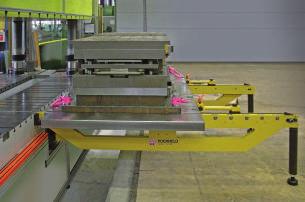
7 Roller and ball bars for easy and safe die change Applications: Fits in T-slots and rectangular slots of press beds for easy die change die change streamlining Roller bar, hydraulic, medium loads Roller bar, hydraulic, heavy loads Option with cover sheet Roller bar, hydraulically lifted for heavy loads, for linear movement of dies: On the underside of the roller bar lifting pistons are provided. Pressure is applied to these pistons using hydraulic pressure generators, which lift then the complete roller bar. The die positioned on the roller bars is not in contact with the table top and can be easily moved and positioned. The basic bodies are made from a high-strength and robust aluminium alloy. Max. operating pressure: 400 bar Load-bearing capacity: up to 160 kn/m, roller spacing 50 mm. Any length up to 2500 mm is possible using modular segments. Fastening of the roller bar using a fastening plate. Roller bar, hydraulically lifted for medium loads, for linear movement of dies: The lifting pistons are provided below each roller allowing rollers to be lifted individually. The basic bodies are made from a high-strength aluminium alloy. Lifting pistons are provided below each roller allowing each roller to be lifted individually. Max. operating pressure: 120 bar. Max. load-bearing capacity: 99 kn/m, flexible roller spacing and orientation. Any variable length in a single piece design up to 2900 mm. Fastening of the roller bar using a fastening plate or a wedge lock. Ball bar, hydraulic (with wedge lock) Roller bar, spring-loaded Ball bar, spring-loaded, with wedge lock Ball bar, spring-loaded, with screw fastening Ball bar, hydraulically lifted for medium loads, for flexible horizontal movement of dies: Oil pressure is applied using a hydraulic pressure generator to lift each ball bar individually. The die positioned on the ball bars is not in contact with the table top and can be easily moved. Max. operating pressure: 100 bar Max. load-bearing capacity: 55 kn/m, flexible ball spacing. Any length in a single piece design up to 2900 mm. Fastening of the ball bar using a fastening plate or a wedge lock. Ball bar with spring pack for lightweight loads for flexible horizontal movement of dies: When preloaded, the balls project over the table level by up to 2 mm. When the die is clamped, the balls are pressed into the bar body against the spring force until they are flush with the table level. Max. load-bearing capacity: 27 kn/m, flexible ball spacing. Any variable length in one-piece design up to 2900 mm. Fastening of the ball bar using a fastening crossbar or a wedge lock. Roller bar with spring pack for medium loads, for linear movement of dies: Function and design of the roller bar similar to spring-loaded ball bars. Load-bearing capacity slightly increased thanks to the use of rollers. Max. load-bearing capacity: 66 kn/m, flexible roller spacing and orientation. Any variable length in one-piece design up to 2900 mm. Fastening of the roller bar using a fastening crossbar or a wedge lock. Load: kg Hole: mm 215 Load: kg Hole: mm Ball and roller inserts with spring pack For installation in tables without T-slots: The spring-loaded ball and roller inserts are individually inserted into drilled holes. The function is similar to that of ball or roller bars with a spring pack. Max. load-bearing capacity: 2200 N, stroke up to 3 mm
8 Roller bar for heavy loads, hydraulic lifting of the complete bar (max. 400 bar) Infeed bevel to prevent the first roller from damage Option: Slip-on cap for T-slots with different height (optional extra) Connecting thread on both sides can be ordered as variant B (from L = 500 mm + preferred lengths) Connecting thread Pin hole for fastening Stroke 2 mm 1 segment = 250 mm length Cheese head screw DIN 933, M 8 x 16 (DIN EN 24017) M 8, 12 deep Fastening plate (the fastening plate is supplied with the roller bar) Press bed Slot (a) (mm) Height (h) (mm) Slot height max. (h) (mm) Max. load/ roller (in kn) Number of rollers per segment = 250 mm Connecting thread Max. operating pressure (bar) Roller Ø (mm) Stroke (mm) Oil requirement / segment (cm 3 ) D (mm) t (mm) A ,0 6,4 8, G 1 8 G 1 8 G ¼ x x x ,54 1,60 2,00 6,5 8,5 8, Other heights and lengths are available on request. Max. temperature 100 C. Inch dimensions on request Connecting thread on both ends can be ordered as variant B (from L = 500 mm + Preferred lengths) Part no. Slot (a) (mm) Length (L) (mm) Max. load (kn) at 400 bar L L L L L L L L L L L L L L L L L L L L L * 300 * two-piece design Dimensions printed in bold are the preferred lengths. On request these are available with a steel sheet cover. Part no. Slot (a) (mm) Length (L) (mm) Max. load (kn) at 400 bar L L L L L L L L L L L L L L L L L L L L L L * 320 Part no. Slot (a) (mm) Length (L) (mm) Max. load (kn) at 400 bar L L L L L L L L L L L L L * 400 Fastening plate, short hose and 90 swivel banjo coupling are supplied with the bar. 216

9 RH-rollblocks, rectangular style for ASA T-slots (3,000 psi) Advantages: modular design provides quick delivery each roller provides linear movement rolling resistance is 1-3% of the die weight each roller is a prelubricated cam roller bearing mounted in a common block rollblock can be secured with the included plate retainer or with pins mounted in the base of the T-slot Application: exact height adjustment by precision lowering of the lifting column These rollblocks are used in pairs or sets to lift the die and provide a roller surface to easily roll the die in and out during the die change process. For use in ASA B T-slots specifications or rectangular slots, see chart below for dimensions. Deeper T-slots can be shimmed to suit Description: The RH rollblock consists of a bar with rollers, mounted in the upper channel. When pressurized the internal pistons push down against the bottom of the T-slot, lifting the roller assembly and die. Recommended operating pressure is 3,000 psi. Pressure range is 1,000 to 5,800 psi maximum. A safety circuit relief set for 10% over the operating pressure, must be included to prevent pressure intensification caused by rollblock overload. See Section 7 of this catalog for pumps or valve packages. Rollblocks for 22, 28, and 36mm Metric T-slots sizes also available. Slot size 13 / / 16 a h Part No. Based on these parameters, we will devise the ball bar for your specific application. Please contact us, we will be pleased to offer you advice! A.US 217 T-slot size L (in)* Max. load per roller at 3,000 psi # of Rollers Max. lift capacity at 3,000 psi RH / ,760 RH / ,520 RH / ,280 RH / ,040 RH / ,800 RH / ,500 RH / ,000 RH / ,500 RH / ,000 RH / ,500 RH / ,000 RH / ,500 RH / ,000 Stock Items *Intermediate, Metric, and Longer Lengths Available
10 Roller bar for medium loads, steel housing, hydraulic lifting of individual rollers (max. 120 bar) Stroke Optional extra: wedge lock G Optional extra: roller turned by 90 Connecting thread on both ends h -0,2 B K I L 3,5 (G 1 / 8 ) 4,5 (G 1 / 4 ) R = Fastening plate K = Wedge lock (optional) E = Size of thread F = Depth of thread D a a h +0,2 c M Wedge lock bolt (one side) M Tmax.: 100 C Higher temperatures on request 0ϒ 90ϒ Roller orientation Load-bearing rollers can be mounted in the longitudinal direction of the roller bar (0 = standard) as well as in a crosswise direction (90 ). Please indicate the direction of the roller, e.g. X = 90 Slot width (a) (mm) /16 1-1/16 Min. slot height (h) (mm) 29,5 37, ,5 29,4 38 Standard slot height (h) (mm) 3o ,4 38,9 Roller Spacing G min. (mm) Roller spacing G standard (mm) Roller spacing G max (mm) L min. *) *) *) *) *) *) L max Stroke (mm) Load-bearing capacity/roller (kn) 1,14 1,85 3,0 4,5 1,14 1,85 Connecting thread G1/8 G1/8 G1/4 G1/4 G1/8 G1/4 Oil requirement/l roller insert (cm 3 ) 0,10 0,31 0,51 0,76 0,10 0,31 B (mm) C (mm) D (mm) E (mm) M5 M5 M6 M6 M5 M5 F (mm) l (mm) , K (mm) 8 8, M (mm) 22, , ,5 30 *) L min. depends on the roller spacing G between at least 3 rollers. Loadbearing capacity indicated per roller bar. K=Wedge lock R=Fastening plate Fastening plate, short hose (250 mm long) and 90 elbow coupling are supplied with the bar. Example of ordering: L1415 K without suffix Example of ordering: L1445 R G60 H43 X B Rollar bar hydraulic Roller bar hydraulic Slot width 28 mm Slot width 28 mm Length 1415 mm Fastening: wedge lock Length 1445 mm Standard slot height Roller spacing 60 mm Fastening: fastening plate Standard roller orientation (0 ) Slot height 43 mm Roller orientation (90 ) Roller bar variations, hydraulically lifted (max. 120 bar) If the appropriate roller bar for your specific application is not included in the tables of standard bars, our range of variations offers a solution. Fewer rollers also means that the roller bar will be offered at a lower price. Select slot height, the ball spacing and the bar length to create a variation for your application. e.g. a=28 mm e.g. fastening plate=r Within the limits indicated in the table of dimensions the following parameters can be freely selected: Slot height (h) The sliding clamp contains a high-pressure spindle which is manually screwed against the tool or the workpiece. The clamping force is built up by turning the hexagon sw1 with a torque wrench and by positioning the wedge system. e.g. h=43 mm Spacing of rollers (G) and load-bearing capacity of the roller bar By changing the spacing of the rollers the load-bearing capacity is indicated for the full length of the roller bar. Therefore, both the load-bearing capacity and the roller spacing must be selected to suit the die weight and the die supporting length. Please indicatee the desired roller spacing or load-bearing capacity of the roller bar, or the maximum die weight and the die dimensions. e.g. G=60mm or load-bearing capacity per roller bar=72 kn or number of rollers=24 or die weight and outside dimensions Length of the roller bar (L) The possible length of the bar is obtained from the roller spacing (G) and the parameter (M). Just indicate the theoretical length (e.g. the length of the table) for your roller bar. Please note that a roller bar must be equipped with at least 3 rollers. e.g. L=1445mm Roller orientation Load-bearing rollers can be orientation in the longitidinal direction of the roller bar (0 = standard) or in a crosswise direction (90 ). Please indicate the orientation of the rollwers required. e.g. X=90 Based on these parameters, we will devise the ball bar for your specific application. Please contact us, we will be pleased to offer you advice! 218

.")
11 Hydraulic roller bar, steel housing standard 1-1/16 inch sizes in stock Application: These roller bars are used in pairs or sets to lift the die and provide a roller surface to easily roll the die in and out during the die change process. For use in ASA T-slots specifications or rectangular slots 1-1 / 16 inch wide. Deeper T-slots can be shimmed to suit. Description: The roller bar consists of a bar that is equipped by hydraulically operated supporting rollers for movement in line with the bar. Rollers can be positioned for front to back or left to right movement. Maximum operating pressure is 1,740 psi (120 bar). A circuit relief valve must be provided to prevent pressure intensification caused by overloading the rollers. Advantages: each roller provides linear movement roller bar includes wedge lock retainer other sizes available upon request steel housing Important notes: G 1/4 ports on both ends to couple the roller bars together to suit special lengths. See catalog page B for additional data, sizes and roller bar. HF-G1/4-G1/4-CU Part No. Length Max. load per Max. lift capacity # of Slot inch (mm) roller lbs (kn) lbs (kn) Rollers (inch) Weight L600KG (600) 415 (1.85) 4,158 (18.50) / kg L900KG (900) 415 (1.85) 6,236 (27.75) / kg L1200KG (1200) 415 (1.85) 8,315 (37.00) / kg HCR L1500KG (1500) 415 (1.85) 10,394 (46.25) / kg Accessories HF-G1/4-G1/4-CU Coupling Union, G 1 / B.US 219
12 Ball bar, steel housing, hydraulically lifted (max. 100 bar) Stroke Optional extra: wedge lock G Connecting threads on both ends h -0,2 B K I L 3,5 (G 1 / 8 ) 4,5 (G 1 / 4 ) R = Fastening plate K = Wedge lock (optional) E = Size of thread F = Depth of thread D a a h +0,2 c M Tmax.: 100 C Higher temperatures on request Slot width (a) (mm) /16 1-1/16 Min. slot height (h) (mm) 29, ,4 37,4 Standard slot height (h) (mm) ,4 38,9 Ball spacing G min. (mm) Ball spacing G standard (mm) Ball spacing G max (mm) L min. *) *) *) *) *) *) L max Stroke (mm) Load-bearing capacity/ball (kn) 0,.79 1,1 1,5 2,5 0,79 1,1 Connecting thread G1/8 G1/8 G1/4 G1/4 G1/8 G1/4 Oil requirement/ ball insert (cm 3 ) 0,08 0,23 0, ,08 0,23 B (mm) C (mm) D (mm) E (mm) M5 M5 M6 M6 M5 M5 F (mm) l (mm) , K (mm) 8 8, M (mm) 22, , ,5 30 *) L min. depends on the ball spacing G between at least 3 balls. Indication of the load per ball bar; K=Wedge lock R=Fastening plate Fastening plate, short hose (250 mm long) and 90 elbow coupling are supplied with the ball bar. Example of ordering: L1415 K without suffix Rollar bar hydraulic Example of ordering: L1445 R G60 H43 X Roller bar hydraulic Wedge lock bolt on one end Slot width 28 mm Slot width 28 mm Length 1415 mm Fastening: wedge lock Length 1445 mm Standard slot height Roller spacing 60 mm Fastening: fastening plate Standard roller orientation (0 ) Slot height 43 mm Roller orientation (90 ) M Ball bar variations, hydraulically lifted (max. 120 bar) If the appropriate ball bar for your specific application is not included in the tables of standard bars, our range of variations offers a solution. Fewer balls also means that the ball bar will be offered at a lower price. Select slot height, the ball spacing and the bar length to create a variation for your application. e.g. a=28 mm e.g. example of fastening=r Within the limits indicated in the table of dimensions the following parameters can be freely selected: Slot height (h) If for your application the slots are not as high as in our standard design, indicate th corresponding dimension. If for your application the slots are higher than our standard design, spacer bars may be inserted. e.g. h=44 mm Spacing of balls (G) and load-bearing capacity of the ball bar By changing the spacing of the balls the load-bearing capacity of the ball bar may be varied. Please note that the load-bearing capacity is indicated for th full length of the ball bar. Therefore, both the load-bearing capacity and the ball spacing must be selected to suit the die weight and the die supporting length. Please indicatee the desired roller spacing or load-bearing capacity of the ball bar, or the maximum die weight and the die dimensions. e.g. G=60mm or load-bearing capacity per roller bar=36 kn or number of rollers=24 or die weight and outside dimensions Length of the ball bar (L) The possible length of the bar is obtained from the ball spacing (G) and the parameter (M). Just indicate the theoretical length (e.g. the length of the table) for your ball bar. Please note that a ball bar must be equipped with at least 3 balls. *)e.g. L=1445mm Based on these parameters, we will devise the ball bar for your specific application. Please contact us, we will be pleased to offer you advice!
13 Ball bar with spring pack Stroke K = Wedge lock (optional) S = Screw fastening K = Wedge lock (optional), bolt on one end Ball bar with spring pack Tmax.: 100 C Higher temperatures on request Slot width (a) (mm) Min. slot height (h) (mm) Standard slot height (h) (mm) " " 29, , ,4 38, *) *) *) *) *) *) ,22 0,42 0,63 1,00 0,22 0, , , , , M6 M8 M10 M10 M6 M8 27, ,5 27, , ,5 12,5 15 Ball spacing G min. (mm) Ball spacing G standard (mm) Ball spacing G max. (mm) L min. (mm) L max. (mm) Stroke (mm) Load-bearing capacity / ball (kn) B (mm) C (mm) C1 (mm) D (mm) E (mm) M (mm) N (mm) *) L min. depends on the ball spacing G with at least 3 balls Indication of the load per ball bar; K = Wedge lock, S = Screw fastening Example of ordering: L1385 K without suffix Ball bar spring-loaded Slot width 36 mm Length 1385 mm Fastening: wedge lock Standard slot height Standard ball spacing Ball bar variations with spring pack If the appropriate ball bar for your specific application is not included in the tables of standard bars, our range of variations offers a solution. Fewer balls also means that the ball bar will be offered at a lower price. Select the slot height, the ball spacing and the bar length to create a variation for your application. e.g. e.g. a = 36 mm fastening screw = S Within the limits indicated in the table of dimensions the following parameters can be freely selected: Slot height (h) If for your application the slots are not as high as in our standard design, indicate the corresponding dimension. If for your application the slots are higher than our standard design, spacer bars may be inserted. e. g. h = 50 mm Spacing of balls (G) and load-bearing capacity of the ball bar By changing the spacing of the balls the load-bearing capacity of the ball bar may be varied. Please note that the load-bearing capacity is indicated for the full length of the ball bar. Therefore, both the loadbearing capacity and the ball spacing must be selected to suit the die weight and the die supporting length. Please indicate the desired ball spacing or load-bearing capacity of the ball bar, or the maximum die weight and the die dimensions. e.g. G = 35 mm Example of ordering: L1380 S G35 Ball bar spring-loaded Slot width 36 mm Length 1380 mm Fastening: screw Ball spacing 35 mm H50 Based on these parameters, we will devise the ball bar for your specific application. Please contact us, we will be pleased to offer you advice! Slot height 50 mm or load-bearing capacity/bar = 38 kn or number of balls = 38 or die weight and outside dimensions Length of the ball bar (L) The possible length of the bar is obtained from the ball spacing (G) and the parameter (M). Just indicate the theoretical length (e.g. the length of the table) for your ball bar. Please note that a ball bar must be equipped with at least 3 balls. *) e.g. L = 1380 mm
14 Roller bar with spring pack Stroke K = Wedge lock (optional) S =Screw fastening K = Wedge lock (optional), bolt on one end Optional extra: Roller turned through 90 Roller insert spring-loaded Roller orientation The load-bearing rollers can be mounted in the longitudinal direction of the roller bar (0 = standard) as well as in a crosswise direction (90 ). Please indicate the direction of the roller, e.g. X = 90 Tmax.: 100 C Higher temperatures on request Slot width a (mm) Slot height min. (h) (mm) Standard slot height (h) (mm) Roller spacing G min. (mm) Standard roller spacing G (mm) Roller spacing G max. (mm) L min. (mm) L max. (mm) Stroke (mm) Load-bearing capacity / roller (kn) B (mm) C (mm) C1 (mm) D (mm) E (mm) M (mm) N (mm) " " 28,5 34, ,5 28,5 34, ,4 38, *) *) *) *) *) *) ,6 0,9 1,4 2,4 0,6 0, , , , , M6 M8 M10 M10 M6 M8 27, ,5 27, , ,5 12,5 15 *) L min. depends on roller spacing G with at least. 3 rollers Indication of the load per roller bar. K = wedge lock; S = fastening plate Example of ordering: L1385 K without suffix Roller bar, spring-loaded Example of ordering: L1380 S G35 H52 Roller bar, spring-loaded Slot width 36 mm Slot width 36 mm Length 1385 mm Length 1380 mm Fastening: wedge lock Fastening: screw Standard Standard slot height roller spacing Roller spacing 35 mm Slot height 52 mm Standard roller orientation (0 ) X Roller orientation of 90 Roller bar variations with spring pack If the appropriate roller bar for your specific application is not included in the table of standard bars, our range of variations offers a solution. Fewer rollers also means that the roller bar will be offered at a lower price. Select the slot height, the roller spacing and the bar length to create the correct variation for your application. Within the limits stated in the table of dimensions, the following parameters can be freely selected: Slot height (h) If, in your application, the slot height does not correspond to our standard design, please indicate the required dimension. If slots are higher than in our standard design, spacers can be provided. e.g. h = 45 mm Roller spacing (G) or load-bearing capacity of the bar By changing the roller spacing the load-bearing capacity of the roller bar can be varied. Please note that the indicated load-bearing capacity applies to the complete bar length. This means that the load-bearing capacity / the roller spacing must be adapted to the die weight and the die supporting length. Please indicate the desired roller spacing or the desired load-bearing capacity of the roller bar or the maximum die weight and the die dimensions. e.g. G = 35 mm or load-bearing capacity per bar 92.1 kn or number of rollers = 38 or die weight and outside dimension Roller bar length (L) The possible bar length is obtained as a function of roller spacing (G) and parameter (M). Just indicate the theoretical length (e.g. the table length) for your roller bar. Please note that a roller bar must be provided with at least 3 rollers e.g. L = 1380 mm S = fastening of screw K = wedge lock By means of these parameters we will determine the roller bar for your specific application. Please contact us, we will be pleased to give you any advice you may require Roller orientation The rollers can be orientated in longitudinal direction of the roller bar (0 = standard) or in crosswise direction (90 ). Please indicate the orientation of the rollers e.g. X =
 29,9 31,9 43,4 52,4 C (mm) 31,5 34,0 45,5 54,5 Ø D (mm) 20 24 30 40 Part no. 8.1210.0605 *Other strokes available on request 8.1210.0611 8.1210.0618 8.1210.0622 Design with flange Max.")
 31,5 34,0 45,5 54,5 Ø D (mm) 20 24 30 40 E (mm) 3,5+0,1 3,5+0,1 4,5+0,1 5,5+0,1 Ø F (mm) 24,5 29,5 34,5 47,5 Ø G (mm) 25+0,2 30+0,2 35+0,2 48+0,2 Part no. 8.1210.")
15 Inserts with spring pack Roller insert Design without flange Max. load (N) *Stroke (mm) 1,5 2,0 2,0 2,0 A (mm) 30,0+0,1 32,0+0,1 43, ,5+0,1 B (mm) 29,9 31,9 43,4 52,4 C (mm) 31,5 34,0 45,5 54,5 Ø D (mm) Part no *Other strokes available on request Design with flange Max. load (N) *Stroke (mm) 1,5 2,0 2,0 2,0 B (mm) 29,9+0,1 31,9+0,1 43, ,4+0,1 C (mm) 31,5 34,0 45,5 54,5 Ø D (mm) E (mm) 3,5+0,1 3,5+0,1 4,5+0,1 5,5+0,1 Ø F (mm) 24,5 29,5 34,5 47,5 Ø G (mm) 25+0,2 30+0,2 35+0,2 48+0,2 Part no *Other strokes available on request Ball insert Design without flange Max. load (N) *Stroke (mm) 1,5 1,5 2,0 3,0 A (mm) 24,0+0,1 28,5+0,1 34,0+0,1 45,5+0,1 B (mm) 23,6 28,5 34,0 44,8 C (mm) 25,5 30,0 36,0 48,0 Ø D (mm) Part no *Other strokes available on request Design with flange Max. load (N) *Stroke (mm) 1,5 1,5 2,0 2,0 B (mm) 23,5 28,5 34,0 44,0 C (mm) 25,2 30,2 36,0 46,0 Ø D (mm) E (mm) 3,5+0,1 4,0+0,1 4,5+0,1 5,6+0,1 Ø F (mm) 24,5 29,5 34,5 47,5 Ø G (mm) 25+0,2 30+0,2 35+0,2 48+0,2 Part no *Other strokes available on request Inserts have 100% lift capacity, and are approved for use up to 100 C (212 F). Inserts for higher temperatures may be available on request. H9 = mm
 Roller Ø (mm) B (mm) C (mm) Ø d (mm) Part no. 22 28 36 32 32 39 250 250 250 6.4 6.4 7.8 16 x 12 16 x 12 19 x 12 39.5 49.5 62.5 23 33 43 5 5 6 8.1834.")
16 Roller conveyor without lifting universal use Roller conveyor, segment 250 mm Roller bar width A (mm) Max. load (kn) Segment length (mm) Max. load/roller (kn) Roller Ø (mm) B (mm) C (mm) Ø d (mm) Part no x x x These universal roller conveyors have been developed for easy and safe conveying of heavy dies. All roller conveyors are manufactured in segments of 250 mm to which further segments can be added until the desired length is obtained. The basic bodies of the roller conveyors are made of a high-strength and robust aluminium alloy. The roller bars are fastened through mounting holes provided in the segments. HILMA/Carr Lane Roemheld also supplies longer singlepiece roller conveyors. Other variations A closer arrangement of the rollers increases the load-carrying capacity Increased load-carrying capacity achieved by package design Overall lengths of max mm in a single-piece design are possible. 224
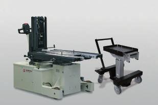
17 Carrying consoles for easy and efficient die change on the press bed Color: RAL 1004, golden yellow Carrying console, hanging The carrying consoles are hung in the hooks on the die changing side of the press. The hooks are supplied with the consoles. The consoles are used as a pair. Their size must be selected to suit the highest die weight. The die is loaded onto the consoles using a crane or a forklift truck. The carrying rollers consist of high-strength hardened needle bearings. The end stop can be bypassed in one direction. The surface is provided with a shock-resistant coating in RAL 1004, golden yellow. Hanging consoles may be used for several presses. In this case, an additional set of hooks is required. Carrying console, supported In order to cope with heavy and large dies, the console is provided with an additional support. For compensating for unevenness on the floor, the supports are designed as adjustable supports with a balland-socket joint. The height may be changed subsequently by ±60 mm. The end stop can be bypassed in one direction. Konsole Typ 1835 Traglast/Paar k Carrying console, swivelling This console is permanently fastened to the press bed and can be pivoted into the die changing position. This type is particularly recommended when the available space in front of the press bed is limited, or if removal and intermediate storage of the console is not possible or wanted. For carrying rollers, end stop and surface coating, see above. Special designs of carrying consoles are available on request
18 Carrying console, hanging Locking pin DIN Ø 16 x 40 Socket head cap screw DIN 912-M 16 x 110-8,8 Ma = 120 Nm Hole pattern Press bed Hook Console Scope of supply: 2 carrying consoles (1 pair) 4 hooks screws and pins not included. Part no. for 1 pair Max. load/ pair (kn) Length of support Dimensions (mm) (L) (mm) a+1 b c ±0,1 d h Weight/pair (kg) M16 Ø M16 Ø M16 Ø M16 Ø M16 Ø M16 Ø M16 Ø M16 Ø M16 Ø M16 Ø hooks are supplied with the consoles. Screws and pins not included. available at short notice 1 additional set of hooks (= 4 OFF) part no (40 kn)
19 Bed upper edge Carrying console, supported Console kn Locking pin DIN 1481 Socket head cap screws DIN 912 M16 x110, 8.8 M a = 120 Nm Locking pin DIN 1481 Ø16 x 40 Socket head cap screw DIN 912 Console kn Bed upper edge Socket head cap screws DIN 912 M16 x 50 and M16 x 110 M a = 120 Nm Locking pin DIN 1481 Ø16 x 50 Bed upper edge Console kn Press bed Hook When ordering, please specify the exact height of support Scope of supply: Console 2 carrying consoles (1 pair) Support 4 hooks 2 supporting feet screws and pins not included Support with ball-and-socket joint (+/-60 mm) please specify support height (+/-60 mm) Socket head cap screws DIN 912 M24 x 80 und M24 x 160 M a = 250 Nm Locking pin DIN 1481 Ø20 x 100 Threaded holes M16 for eye bolts (transport by means of fork stacker) Part no. for 1 pair Max. load/pair (kn) Length of support Dimensions (mm) (L) (mm) a+1 b c ±0,1 d e f h x M16 Ø M16 Ø M16 Ø M16 Ø M16 Ø M16 Ø M16 Ø M16 Ø M16 Ø M16 Ø M16 Ø M16 Ø M16 Ø M24 Ø M24 Ø M24 Ø M24 Ø hooks and 2 supports are supplied with the consoles. Screws and pins not included. available at short notice Example of ordering: , SH 1000 console 1000 mm long max. 20 kn height of support 1000 mm 1 additional set of hooks (= 4 OFF) part no (40 kn), part no (100 kn), part no (250 kn) Weight/pair (kg)
 4 holders (premounted) screws")
20 Carrying console, swivelling Hole pattern Holder Console Socket head cap screws DIN 912 M16 x 40, 8.8 M a = 120 Nm Locking pin DIN 1481 Ø10 x 50 Lock Locking pin DIN 1481 Press bed Socket head cap screw DIN 912 Scope of supply: 2 carrying consoles (left and right side) 4 holders (premounted) screws and pins not included The carrying console is swivelling on the left and right side Part no. for 1 pair Max. load/pair (kn) Length of support Dimensions (mm) (L) (mm) a ±0,2 b ±0,1 c ±0,1 d e g h i k ±0, M16 Ø , M16 Ø , M16 Ø , M16 Ø , M16 Ø , M16 Ø , M16 Ø , M16 Ø ,5 Carrying consoles are supplied in pairs with holders fastened, ready for connection. Screws and pins not included. Special designs and double-swivel consoles are available on request. Special designs of carrying consoles, e.g. sliding carrying consoles are available on request


21 Die changing station, electrically driven Dies up to a weight of 200 kn Die changing system directly adapted to the press This new die changing system with special push-pull drive makes handling of dies easier and ensures time-saving and accident-free change of dies with a maximum weight of 25 tons in places difficult to access. (Higher load-bearing capacities on request) Description: The cost-effective drive system has been developed on the basis of standard die consoles and can be easily installed as it requires only little space. Thus, it is very suitable for both retrofitting and new constructions. The drive unit and the carrying console are hung in hooks provided on the press for this purpose and then locked. The die is deposited on the consoles using a crane or a forklift truck. After the die has been deposited, it can be connected to the changing station by means of a pushand-pull system. The integral chain drive system allows the user automatic die loading and positioning, just by depressing a pushbutton on a separate remote control pendant. During a die change, the press bed is free, i.e. the push-pull elements do not project over the press bed. Also the rear side of the press is completely free. This changing station is suitable for almost any press, can be easily removed and is easy to handle. Advantages: Besides the reduction of non-productive set-up time, the die changing system offers further important benefits to the user: maximization of profits due to less downtime smaller production batches are possible due to shorter set-up times greater safety for man and machine safe and accident-free handling of dies with less effort, thus creating a more ergonomic place to work Roller and ball bars in the T-slots of the table provide for easy insertion of the die, either manually or automatically. Damage to the die causing production loss is avoided. Individual solutions including automatic die changing and integration in the press are possible


22 Die changing station, electrically driven Variations of the die changing station Various variants with two driven, synchronized drive consoles and with drive motor at left/right side. The length of the console, adaptor and loads are flexibly selectable. Die changing console with drive and side loading of the press. Drive console with motor mounted at the right side Load: 100 kn, length: 2500 mm
.")


23 Die changing console, manually driven Low-cost alternative to an electric drive Die changing system directly adapted to the press This new die changing console with crank handle and transmission gearing makes handling of dies easier and ensures time-saving and accident-free change of dies with a maximum weight of 6 tons in places difficult to access. (Higher loads on request). Description: The cost-effective drive system has been developed on the basis of standard die changing consoles and can be easily installed as it requires only little space. Thus, it is very suitable for both retrofitting and new constructions. The drive console is hung in hooks provided on the press for this purpose and then locked. The die is deposited on the consoles using a crane or a forklift truck. After the die has been deposited, it can be connected to the push-pull docking device of the die changing console. A crank handle at the side allows the user a safe and effortless insertion and positioning of the die. During a die change, the press bed is free, i.e. the pushpull elements do not project over the press bed. Also the rear side of the press is completely free. This die changing console is suitable for almost any press, can be easily removed and is easy to handle. Special features: Besides the reduction of non-productive set-up time, the die changing system offers further important benefits to the user: maximization of profits due to less downtime smaller production batches are possible due to shorter set-up times more safety for man and machine safe and accident-free handling of dies with less effort, thus creating a more humanized place of work Roller and ball bars in the T-slots of the bed provide for easy insertion of the die, either manually or automatically. Damage to the die causing production loss is avoided. Individual solutions including automatic die change and integration in the press are possible
24 Die changing console, manually driven L +40 L Push-pull docking device 345, ±0,1 1,5 3 M16 Ø Press bed h Hooks When ordering, please specify the exact support height Scope of supply: 2 carrying consoles (1 pair) 4 hooks 2 supporting feet Console Support Please indicate support height (± 60 mm) Adjustable foot with ball joint (± 60 mm) Threaded hole M 16 for eye screws (transport by forklift truck) Technical data: Length of the console: as per customer's request Support height: as per customer's request Die weight: up to 60 kn Dimensioning and further technical details in the course of the project. Crank handle can be easily moved by one hand with a die weight of 60 kn
25 Die changing cart manually movable, with optional auxiliary drive with safety docking station Rotational handle Side bars Additional ball support for the area towards the press bed Fixed rear bar Removable frontal safety bar Parking brake Lifting column Safety docking station to lift / lower the balls Figure RW with auxiliary drive Applications: Die changing carts RW facilitate the handling of mediumweight dies and enable dies weighing up to 500 kg to be safely transported in an easy and time saving way. All cart types are especially designed for pressing and punching dies as well as for injection and casting molds. Description: Die changing carts RW are manually moved. For easier movement, the front axle can optionally be equipped with a battery driven auxiliary drive. The die changing table is equipped with ball inserts which facilitate the manual insertion of the dies. During the transport, the ball inserts are lowered and the die is protected against movement. In addition, the die is secured against falling down by safety bars at all sides of the die changing table. The die changing table can be adjusted in height by a hydraulic lifting column with single-lever foot operation. For transport, the centre of gravity of the load must be positioned in the centre of the cart and the lifting columns must be completely lowered. Safety docking station During the transport of the die, the balls are always lowered and the die is protected against movement. Lifting of the ball inserts is made by successful docking to the press bed. The die weight is supported at the press bed. Advantages: Sturdy chassis with two guide rollers and two fixed rollers Single-lever foot operation for internal protected piston pump time-saving die change material gentle transport highest safety by automatic docking station and antislip protection easy movement by optional battery driven auxiliary drive sturdy and scratch-proof ball table with hard-anodized surface documentation and design in compliance with CE standards exact positioning exact height adjustment by precision lowering improved ergonomics for the user additional protection against falling down of dies by safety bars on all sides safe positioning of the cart by pedal parking brake 1. Transport 2. Docking Lifting column extended Lifting column lowered Ball inserts lowered Ball inserts lifted Die on table plate Die on ball inserts 1 2 Docking situation Version with safety docking station and ball table
26 Die changing cart technical data, dimensions Accessories: Hooks Technical data Die Changing Cart RW Max. load capacity: 500 kg Table height H Table sizes Version Length A x width B [mm] x x Lifting range Version Total stroke Usable stroke Min. table height H Max. table height H [mm] [mm] [mm] [mm] B Versions The die changing cart RWA is available in 2 table sizes and 3 stroke ranges. Every version can optionally be equipped with an auxiliary drive. Optional auxiliary drive All elements of the auxiliary drive are integrated in the front axle: the electric motor including gear, long-life batteries with high energy density and a power control for optimum control of the motor. The rotational handle consists of two solid handles, speed and direction of the drive can be controlled by means of a lever at the right handle. An integrated level compensation ensures an optimum contact pressure of the drive wheel on the hall floor. A covering protects the drive against shocks and splash water. The high drive torque of the electric motor (17 Nm / 20 da N) facilitates considerably the movement of the changing cart. A 285 Technical data Auxiliary drive Running performance [km] 2 with full load (5 with average load) Displacement speed [km/h] 3 Charging time (approx. 90 %) [h] 1.5 to 3 (depending on the battery charger) Battery 24 V DC, Ni-MH, 140 Wh (6 Ah) Part numbers Table size [mm] Total stroke [mm] Auxiliary drive Part numbers 720 x without x without x without x without x without x without x with x with x with x with x with x with Scope of supply: Die changing cart with one set of hooks and battery charger Accessories Battery charger 1.8 A (included in the delivery) V AC, 50 / 60 Hz Charging time 3 h (approx. 90 %) Part no Dowel pin DIN 1481 Ø 16 x Quick battery charger 4A V AC, 50 / 60 Hz Charging time 1.5 h (approx. 90 %) Part no Ø 16 M 16 Bed level Hooks (Set of 2 off) to position and lock the die changing cart Part no (99) ,5 ± 0,1 68,5 ± 0, Socket head cap screw DIN 912-M 16 x Ma = 120 Nm Dimensions are valid for the infeed height of the die 1.5 mm above the machine table 2 234
 Toggle switch for reduced speed 2.")
27 Die Changing Cart with Electrical Drive RWA with electro-hydraulic lifting platform, die changing table and hydraulic ball bars Operation: The operation of the die changing cart RWA is completely made at the multi-functional drawbar. Rotary switch for continuous and sensitive driving (speed control) Toggle switch for reduced speed 2.0 km/h Push-button for driving with reduced speed and vertical drawbar position Steering (by drawbar) Slide switch for sensitive lifting and lowering of the lifting platform Push-button for lifting/lowering of the balls (as an option) Signal horn and key switch Main current safety switch (EMERGENCY STOP) Multi-functional displayfor display of battery status and operating hours maintenance intervals and error messages Versions as per customer's request: Roller bars instead of ball bars Ball or roller distance Dimensions of the lifting platform Radio remote control Please contact us. Accessories see page 3 of this series. Application: The die changing cart RWA is used for the transport and the change of pressing and punching dies as well as injection and casting molds up to a weight of 1600 kg. Description: The die changing cart RWA is an electrically driven walking and lifting cart, especially equipped for the transport and the change of dies. The electro-hydraulic lifting platform is designed as die changing table with integrated hydraulic ball bars, which facilitate the manual insertion of the dies onto the press table. During the transport, the balls are always lowered and the die is protected against movement. A safety circuit ensures that the die changing cart can only be displaced with lowered ball bars. In addition, the die is secured on the lifting platform by removable front safety bars or side bars. For the transfer of the die to the press, the lifting platform is equipped with a protrusion. Advantages: safe and gentle die transport of heavy dies time-saving die change integrated die changing table with hydraulic ball bars high safety by docking bars and lowerable ball bars protection against falling down of dies by removable side bars simple and central operation with multi-functional drawbar multi-function display on the drawbar robust vehicle technology modular design with standard drive Versions: The die changing cart RWA is available in 2 versions: RWA 1200 max. load capacity: 1200 kg RWA 1600 max. load capacity: 1600 kg* * with reinforced lift mast and 6 instead of 4 ball bars Power supply: The power supply of the electric drive, the lifting platform and the ball bars is made via an installed battery 24 V DC with 240 Ah. This battery can be completely charged within 12 hours with a battery charger included in the delivery. Automatic slow driving at low battery status as well as automatic lift cutout in the case of further discharge. The maximum running performance is approximately 3 hours at full load

![1000 x 800* Ball bars (each 690 mm long) 4o ff 6o ff Ball distance [mm] 75 70 Stroke of the ball bars [mm] 2 2 Max. lifting force / bar [kn] 8.8 8.](/docs-images/75/72110822/images/28-1.jpg "8 Displacement speed [km/h] up to 5 5 Running performance approx. 3 h at full load Empty weight [kg] 1120 1200 Part no. 8.8913.1200 8.8913.1600 * Individual platform sizes and ball distances on request.")
28 Die Changing Cart with Electrical Drive technical data, dimensions Technical data Version RWA 1200 RWA 1600 Max. die weight [kg] Lifting range [mm] Load capacity at the load center of gravity 400 mm [kg] at the load centre of gravity 650 mm [kg] Platform size [mm] 1000 x 800* Ball bars (each 690 mm long) 4o ff 6o ff Ball distance [mm] Stroke of the ball bars [mm] 2 2 Max. lifting force / bar [kn] Displacement speed [km/h] up to 5 5 Running performance approx. 3 h at full load Empty weight [kg] Part no * Individual platform sizes and ball distances on request. Scope of supply: Changing cart with built-in battery Battery charger Lifting platform 4 or 6 hydraulic ball bars Removable side and front bars Further accessories and options in addition to the standard scope of delivery, see next page. Dimensions 624 Removable side bar Accessory: Cable remote control Accessory: Cable remote control Load center of gravity 400 / Removable front bar Ø Ø 150 L2 = Ø Accessory: Docking bar or 6 hydraulic ball bars, 690 mm long and 22 mm wide R1247 Usable depth 779 Removable bar A Usable width 958 Platform width 1000 A-A 2 mm stroke Ball bar Accessory: 741 Quick-disconnect coupler for external Platform depth800 ball bars 1515 A


29 Die Changing Cart with Electrical Drive accessories Quick-disconnect coupler for external ball or roller bars The die changing cart RWA can be equipped with an additional hydraulic control circuit with quick-disconnect coupling for the operation of the hydraulic ball and roller bars in the press table. The operating pressure is 80 bar. Part no.: Docking bars To obtain the exact insertion height at the press table, the lifting platform and the press table can be provided with docking bars. Docking bars for fixing at the changing cart Part no.: Docking bars for fixing at the machine Part no.: Battery filling system Aquamatic Filling station with electric pump for fast filling of the batteries with water. Part no.: mm 262 mm 92 mm Extra battery charger E 230 G* Charging time: 2 h Code class: IP 21 Part no.: * USA version on request Cable remote control with the functions: Lifting/lowering Driving: forwards/backwards Emergency stop (Mounting position see drawing on previous page) Part no.:
Die changing technique
 Die changing Die changing 8 Contents Product group 8 Roller bar, hydraulically lifted for heavy loads (400 bar), lifting of the complete roller bar for medium loads (120 bar), lifting of individual rollers
/2015. Roller and ball bars for easy and safe die change
 Roller and ball bars for easy and safe die change T-slot tolerances acc. to DIN 650 h h n a b c min. max. max. 18 H8 30 +2 12 +2 30 36 1,6 22 H8 37 +3 16 +2 38 45 1,6 28 H8 46 +4 20 +2 48 56 1,6 36 H8
Hydraulic clamping elements
 Hydraulic clamping elements hydraulic 3 Contents Product group 3 Hollow piston cylinder single-acting 3.1403 3.2130 Sliding clamp single-acting compact classic 3.2202 3.2204 Angular clamping element single
L I F T I N G C A R T S
 L I F T I N G C A R T S LIFTING CARTS The prograe for lifting, transporting and storage From the classical forklift trolley to the machine lifter, from furniture dollies to a chassis with 24 tons load
Assembly Products. View Assembly Products at: LINEAR ACTUATORS AND MODULAR UNITS FOR YOUR APPLICATION
 Assembly Products LINEAR ACTUATORS AND MODULAR UNITS FOR YOUR APPLICATION View Assembly Products at: www.clrh.com (636) 386-8022 www.clrh.com Drive, Assembly and Handling Technology Linear Actuators n
Wedge clamps
 Wedge clamps Wedge clamps for dies with tapered clamping edge Without position monitoring up to 160 C* 2.24000 With position monitoring lateral fastening up to 100 C** 2.24001 With position monitoring
/2017. Swing sink clamping element double-acting
 Applications: integrated in press rams integrated in press beds in machine tools and equipment when the available space is limited when temperatures may reach 70 C For power units please see product group
Power Workholding. Power Workholding n Precision Vises n Zero Point Mounting n Assembly and Handling
 Power Workholding Power Workholding n Precision Vises n Zero Point Mounting n Assembly and Handling OUR STORY In 1982 an independent joint venture was established to marry the proven product expertise
Conveyors 12. slide strips roller Conveyors roller elements Conveyor rollers Chain Transfer
 Conveyors slide strips roller Conveyors roller elements Conveyor rollers Chain Transfer Application example conveyors Transport solutions and goods provision 1 2 3 4 5 6 7 8 362 9 1 slide strips Low-wear
/2017. Hollow piston cylinder, single-acting spring clamping hydraulic unclamping
 , single-acting spring clamping hydraulic unclamping Applications: un-pressurized long-term clamping of dies or fixtures on press beds and rams when the space available is limited T-bolt Spring clamping
ALFRA PRESS - overview
 70 ALFRA PRESS 71 ALFRA PRESS - overview ALFRA PRESS AP 250 ALFRA PRESS AP 400 Page 74 Page 78 Control cabinet housing, Control cabinet doors, Mounting panels Control cabinet housing, Control cabinet doors,
MULTI-PERFORMANCE LIFT
 MULTI-PERFORMANCE LIFT 60 MULTI-PERFORMANCE LIFT UNIVERSAL APPLICATIONS THE MULTI-PERFORMANCE LIFT This universally applicable device for standard liftig is a perfect supplement to EXPRESSO s lift2move
01 Product overview KT series order picking trolleys MultiPick trolley Pick and Pack Order picking container
 01 Product overview 01.01 01.09 KT series order picking trolleys 01 KT1 02 KT2 03 KT3 04 KT4 05 KT DRIVE 06 KT3-KOMBI 07 KT ALU 08 KT-R 09 KT-B 01.10 MultiPick trolley 01.11 Pick and Pack 10 MULTIPICK
B Precision Ground Plates and Flat Bars. E Ground Precision Components. G Elastomer-Bars, -Sheets, -Sections
 A Die Sets B Precision Ground Plates and Flat Bars C Lifting and Clamping Devices Shanks, Lifter Studs and Lifting Hooks, Eyebolts Clamping Claws, Screws and Bolts D Guide Elements E Ground Precision Components
Suspension System CS-3000
 Suspension System CS-3000 Straight coupling Elbow coupling (colour) 1015300177 RAL 9006 white aluminium 1015300001 RAL 16 anthracite grey 101530017 RAL 9006 white aluminium 1015300002 RAL 16 anthracite
Dynamic Elements Linear Slides Mechanical Drive Elements Accessories for Mechanical Drive Elements
 8 Dynamic Elements Mechanical Drive Elements Accessories for Mechanical Drive Elements The Dynamic Elements product group of the MB Building Kit System contains components which enable precise linear movement.
Valve Lapping Tool Attachment. Valve / Valve Spring Tools / Jacks / Axle Stands. 27-piece Valve Seat Cutter Set, mm
 Valve Lapping Tool Attachment - facilitates the insertion of valves - automatic change in direction - for use with fine grinding paste - with 8 mm shank - working speed min. 1000 rpm, max. 1250 rpm - 2
Pneumatic Power Valves Series 75/76 Manual, Mechanical, Pneumatic and Electric Valves
 Quic-Pics Catalogue Pneumatic Power Valves Series 75/76 Manual, Mechanical, Pneumatic and Electric Valves Contents: Product Line Overviews 2 Manually Operated Valves 5 Pushbuttons 6 Toggle Switch 8 Knob
ZERO-POINT CLAMPING SYSTEM
 simple. gripping. future. ZERO-POINT CLAMPING SYSTEM 22 Quick Point Grid Plates 3 Quick Point Plates 34 Quick Point Round Plates 39 Quick Point Adaptor Plates 4 Quick Point Clamping Studs 43 Quick Point
The BERNSTEIN CS-3000
 Flexible and efficient: The BERNSTEIN CS-3000 Designers and manufacturers expect modern suspension systems to feature variable configuration, progressive design and complete ease installation. BERNSTEIN
HYDRAULIC CRIMPING TOOLS
 HYDRAULIC CRIMPING TOOLS HT 51 New design two speed hydraulic tool, lightweight and compact, this tool is ideal for working in confined spaces. Having the benefit of spring loaded handles, the dies can
L Standard Parts for Mould Making
 A Die Sets B Precision Ground Plates and Flat Bars C Lifting and Clamping Devices Shanks, Lifter Studs and Lifting Hooks, Eyebolts Clamping Claws, Screws and Bolts D Guide Elements E Ground Precision Components
Profile guide/actuator - RK Compact
 Profile guide/actuator - RK Compact Slimline short-stroke linear actuator for hand adjustment with excellent price-performance ratio Control knob with vernier Simple adjustment of carriage Backlash of
Standard Knockout Punches 10. Punch Kits for Hydraulic Drivers 11. Draw Stud Selection Guide 13, 14, 18. Special Shape Punches
 8 Punching Tools, Hole Saws, Step Bits Page Punching Tools Standard Knockout Punches 10 Slug Buster Knockout Punches 10 Slug Splitter Knockout Punches 10, 12 Punch Kits for Hydraulic Drivers 11 Draw Stud
SCHMIDT PneumaticPress
 Maximum pressing force from 1.6 kn to 60 kn The SCHMIDT PneumaticPress range consists of a modular system suitable for transforming, joining and assembling operations optimally within the pressing capacities
Special sockets for MXTA Series of Driving Type Hydraulic Torque Wrench(CR-MO sockets) MXTA Series of Driving Type Hydraulic Torque Wrench.
 MXTA Series of Driving Type Hydraulic Torque Wrench.") Torque Wrench Torque Wrench MXTA Series of Driving Type Hydraulic Torque Wrench Special sockets for MXTA Series of Driving Type Hydraulic Torque Wrench(CR-MO sockets) Max. working pressure up to 70Mpa,
Torque Wrench Torque Wrench MXTA Series of Driving Type Hydraulic Torque Wrench Special sockets for MXTA Series of Driving Type Hydraulic Torque Wrench(CR-MO sockets) Max. working pressure up to 70Mpa,
Selection Tool. on the Internet at in the section MÄDLER -Tools. Other sizes and designs on request. Connecting Shafts Page 766
 Couplings Overview Friction Clutches Friction Clutches Type B Axial Arrangement Friction Clutches Type C Transversal Flexibility Sliding Hubs with Torsionally-Flexible Coupling Multi-Disk Friction Clutches
Multi-Performance Lift Universal lifting aid for every-day handling tasks
 Multi-Performance Lift Universal lifting aid for every-day handling tasks 125 kg Unique features of the Multi-Performance Lift Curtis-control ensures smooth and safe load transport and handling. The operating
Belt Conveyors GUF-P MINI
 Belt Conveyors GUF-P MINI Conveyor frame profiles mk 2075 mk 2100 mk 2150 22 The minimal install height, as well as the lower walls for direct placement of the conveyor on the machine bed, are ideal for
ROBUSTO Lifter. Your benefits. We have the solutions you need so why not contact us! versatile, flexible, functional, ergonomic
 ROBUSTO Lifter Transport and lifting operations in compliance with occupational safety standards Your benefits versatile, flexible, functional, ergonomic individual applications We have the solutions you
SSC/SSCM. Stock Selector Counterbalanced Trucks
 SSC/SSCM Stock Selector Counterbalanced Trucks Stock Selector Counterbalanced Combines order picking and overhead maintenance capabilities The Big Joe stock selector series is designed and engineered for
> piston force up to 20,1 kn. > operating pressure 250/350 bar. > chemically nitrided body. > piston force up to 44,0 kn. > operating pressure 350 bar
 Vertical and link CLAMPS for DEMANDING TASKS vertical CLAMP > piston force up to 20,1 kn > operating pressure 250/350 bar > chemically nitrided body link CLAMP > piston force up to 44,0 kn > operating
Below the Hook Lifting
 SECTION INDEX S E C T I O N 1 3 BALE LIFTING TONG...-14 BARRIER GRABS...- 14 BEAM TONGS...-14 BEAM, SPREADER Adjustable...-4 Custom...-5 Fiberglass...-4 Fixed...-3 BEAMS, LIFTING Adjustable Hook...-1 Custom...-5
WPP 15 T - Hydraulic table shop press with manual pump and mobile cylinder for professional use
 Hydraulic shop presses WPP 15 T - Hydraulic table shop press with manual pump and mobile cylinder for professional use For all repair and assembly works, e.g.: Straightening Robust frame with perforation
Profile series I-40. System kit Profile series I-40
 Profile series I-40 System kit Profile series I-40 n n n a n n n R n a R 45 Profile series I-40 Contents 1 Technical data/profile machining F f Page 1 2 Page 1 3 Page 1 5 Page 1 8 Profiles Page 2 2 3000
Series SSG - Compressing & stretching device for the Use in the workshop and construction zone
 Compressing and stretching devices Series SSG - Compressing & stretching device for the Use in the workshop and construction zone To manufacture wheel arches, window frames, rain profiles or door edges
Precision levelling wedges Due to their large contact area Bilz precision levelling wedges (PK) for vibration and structure-borne noise insulation
 for vibration and structure-borne noise insulation") 28 Precision levelling wedges Due to their large contact area Bilz precision levelling wedges () for vibration and structure-borne noise insulation offer optimum support and stiffening of the machine bed.
28 Precision levelling wedges Due to their large contact area Bilz precision levelling wedges () for vibration and structure-borne noise insulation offer optimum support and stiffening of the machine bed.
INDUSTRIAL VACUUM SYSTEMS MADE AND MANUFACTURED IN GERMANY RANGE OF ACCESSORIES COMPETENCE CENTRE INDUSTRIAL VACUUMING. Valid from
 INDUSTRIAL VACUUM SYSTEMS MADE AND MANUFACTURED IN GERMANY Valid from 01.01.2019 COMPETENCE CENTRE INDUSTRIAL VACUUMING 2 3 DEAR CUSTOMER, This catalogue provides you with an essential selection of the
TS 5 Transfer System Version 2.0
 Electric Drives and Controls Hydraulics Linear Motion and Assembly Technologies Pneumatics Service TS Transfer System Version.0 The Drive & Control Company 0 Bosch Rexroth AG TS.0 3 0 30 (00. Symbols No.
Crawler excavator R 976
 Crawler excavator R 976 Operating Weight with Backhoe Attachment: 85,3 95,5 kg Operating Weight with Shovel Attachment: 9,8 92,6 kg Engine Output: 4 kw / 544 P Bucket Capacity: 2. 6.6 m³ Shovel Capacity:
Advanced Cold milling machine for economical applications. Cold Milling Machine W 195
 Advanced Cold milling machine for economical applications. Cold Milling Machine W 195 02 03 TWO-METRE FRONT LOADER IN TRIED-AND-TESTED DESIGN FOR EFFICIENT MILLING OPERATIONS. THE MACHINE IS SUITABLE FOR
SCHMIDT ManualPress From 1.6 kn to 22 kn / 360 lbs. to 4,945 lbs.
 SCHMIDT ManualPress From 1.6 kn to 22 kn / 360 lbs. to 4,945 lbs. Efficient manufacturing requires appropriate means of production not always automation. In particular, with small production runs, manual
Modular individual transport system
 EN Modular individual transport system The modular, flexible transport solution You are looking for a possibility to move large and heavy loads on a surface in all directions und position them precisely
SCHMIDT PneumaticPress
 Maximum Pressing orce from 1.6 to 60 kn The SCHMIDT PneumaticPress range consists of a modular system suitable for transforming, joining and assembling operations optimally within the pressing capacities
RK Monitor Mounting... page 254. GT page 264. GT 50, 60, page 274. Support arm / equipment carrier system
 Support arm / equipment carrier system RK Monitor Mounting... page 254 GT 48... page 264 GT 50, 60, 80... page 274 Support arm / equipment carrier system RK Monitor Mounting All purpose mounting for monitors,
Contents. Page. 1. Product description. 2. The AXC line of linear axes. 3. AXLT line of linear tables. AXC and AXS product overview...
 SNR Industry Contents Page 3 1. Product description AXC and AXS product overview... 6-8 Dynamic load ratings of the linear motion systems... 9 Compact modules... 10-11 Linear tables... 12 Telescopic axes...
For more ergonomic workplaces. ErgoMove 1000 and ErgoMove The Electric Drive Systems from Blickle.
 . For more ergonomic workplaces. ErgoMove 000 and ErgoMove 000. The Electric Drive Systems from Blickle. Content Blickle. A company in motion. The ErgoMove principle of added value. Overview: ErgoMove
PULLERS GD_PG_$KT-K10-$KP-ABZI-$PG-UMABZ :31:24
 PULLERS INTERNAL EXTRACTORS Precision internal extractor Slide hammer Suitable for small ball bearings Ideal for limited access areas Centering shaft For the accurate fitting of bearings and bushes 660.0501
Mechanical equipment Pneumatic stamping-unit Hand-toggle-lever presses
 Mechanical equipment Pneumatic stamping-unit Hand-toggle-lever presses Mechanical equipment ST 1092 ST 1292 page 7.03 ST 9041 page 7.04 ST 9062 page 7.05 ST 9067 page 7.05 ST 9072 page 7.06 ST 9075 page
Product Information. Rotary gripping module with angular gripper RW
 Product Information RW RW Flexible. Modular. Compact. Gripper Swivel Module RW Rotary gripper combination, consisting of a rotary module and a 2-finger angular gripper Field of application Gripping and
MA-5200 Series MA-5300 Series
 MA-5200 Series MA-5300 Series Two-Position Actuators General Instructions Application The MA-5200 series and MA-5300 series actuators are used for two-position control of valves and dampers which require
Steps for self-assembly 100 S C.08 Steps for self-assembly 100 L C.10 Steps for self-assembly 75 L C.12 Industrial ladders C.13
 Step system Technical information Test marks Your Partner in matters of safety Founding member of the German Ladder and Mobile Scaffolding Association Founding member of the European Ladder Federation
Demag DC-Pro Chain Hoist Demag DCM-Pro Manulift. The New High Performance Hoists
 Demag DC-Pro Chain Hoist Demag DCM-Pro Manulift The New High Performance Hoists Standard Features All inclusive: popular options are standard Many of the most popular features are integrated into the Demag
> clamping force up to kn. > operating pressure up to 500 bar. > piston with internal thread. > for push- and pull operation
 Block CYLINDERS for VARIOUS DESIGN APPLICATIONS > clamping force up to 155.5 kn > operating pressure up to 500 bar > piston with internal thread > for push- and pull operation > with longitudinal and cross
Technical data/component parts
 Technical data/component parts Demag pillar and wall-mounted slewing jib cranes 191214 en GB 203 814 44 714 IS 132 Manufacturer Terex MHPS GmbH Forststrasse 16 40597 Düsseldorf, Germany www.demagcranes.com
Gripping rotary modules.
 Gripping rotary modules Gripping rotary modules GRIPPING ROTARY MODULES Series Size Page Gripping rotary modules RP 314 RP 1212 318 RP 1216 322 RP 1520 326 RP 2120 330 RP 2128 334 RC 338 RC 1212 342 RC
Hytrol's ABC Conveyor Book
 Hytrol's ABC Conveyor Book WHAT IS A CONVEYOR? A conveyor moves material. A conveyor moves cardboard boxes, wood boxes, metal boxes and plastic boxes. A conveyor can move material This is called a GRAVITY
Demag DC-Pro chain hoist: A new industrial standard Made by Demag
 Demag DC-Pro chain hoist: A new industrial standard Made by Demag All inclusive: fully featured instead of extras price list Many features are already integrated into the Demag DC-Pro chain hoist as standard
PLM series Permanent load lifting magnets
 Lifting gear Load lifting magnets/chain hoists PLM series Permanent load lifting magnets Load-bearing capacity of up to 1 t depending on model despite light weight High standard of safety with simple lever
Automotive lifts from Bosch Reaching new heights
 Automotive lifts from Bosch Reaching new heights For each workshop type: The new automotive lifts from Bosch Electromechanical 2-post lifts VLE 2130 VLE 2130F VLE 2130E VLE 2130EL VLE 2140EL Electrohydraulic
A44 W0...W2: Motorised actuator
 A44 W0...W2: Motorised actuator How energy efficiency is improved Electric cut-off in end position to save energy Features Actuation of control units such as air dampers, gates, butterfly valves, etc.
EZ Tool Articulating Arm
 EZ Tool Articulating Arm EZ tool arm features: Covers a 610 x 762 mm (24 x 30 inch) horizontal rectangular work envelope. Two piece arm with overall length from 864 to 1067 mm (34 to 42 inches). Anodized
CATALOG. Actuated Diaphragm Valve DN PVC-U / PVC-C / PP-H / PVDF / ABS SMART IN FLOW CONTROL.
 CATALOG Actuated Diaphragm Valve DN 15-100 PVC-U / PVC-C / PP-H / PVDF / ABS SMART IN FLOW CONTROL. TABLE OF CONTENTS Type 186 - DN 12-15 (MA 10) 04 General information - Technical specification 04 Sectional
Axis Modules pneumatic
 Axis Modules pneumatic Axis Modules XY-Compensation Order no. Stroke XY-Ebene Handling weight Page ± [mm] recommended [kg] Product Information 6 XY70 3 6 10 XY100 5 12 12 XY160 8 30 14 XY220 10 150 16
Part No. AJS & MATCHLESS SINGLE ENGINE - NEW PARTS Price (incl 17.5% VAT)
") Part No. AJS & MATCHLESS SINGLE ENGINE - NEW PARTS Price (incl 17.5% VAT) Price (excl VAT) 000217 Nut for cylinder base stud, double hexagon 2.90 2.47 000300 Cylinder base stud 3.20 2.72 022516 Stud, cylinder,
Part No. AJS & MATCHLESS SINGLE ENGINE - NEW PARTS Price (incl 17.5% VAT) Price (excl VAT) 000217 Nut for cylinder base stud, double hexagon 2.90 2.47 000300 Cylinder base stud 3.20 2.72 022516 Stud, cylinder,
Machine elements. Pneumatic stamping unit. Toggle-lever presses
 Machine elements Pneumatic stamping unit Toggle-lever presses Machine elements ST 1292 ST 1092 Page 7.03 ST 9041 Page 7.04 ST 9061/62 Page 7.05 ST 9067 Page 7.05 ST 9070/72 Page 7.06 ST 9075 Page 7.07
Air Operated Post Drivers Hydraulic & Manual Post Pullers
 Air Operated Post Drivers Hydraulic & Manual Post Pullers Post Drivers and Pullers Will Drive and Pull a Multitude of Posts in Seconds Rhino Transports Serve as Both Transportation and Display and Conveniently
GTK 80. Technical data
 Industrial square suspension system with open cable duct for heavy loads Modular construction with free accessible cable duct Floor, top-mounting or wall exit options Technical data Material: connecting
Hahn Serie 60 AT. Universal hinge for versatile application. More modern look Improved technology
 Hahn Serie 60 AT Universal hinge for versatile application! More modern look Improved technology 2 4 5 6 7 8 9 2 3 4 5 6 7 8 9 2 Hahn Serie 60 AT For all doors made from metal profile sections NEW! Uniform
EC140B LC VOLVO EXCAVATOR
 VOLVO EXCAVATOR EC140B LC Engine power, gross: 73 kw 98 hp Operating weight: 13.4 ~ 15.2 t 29,529 ~ 33,450 lb Buckets (SAE): 600 ~ 975 l 0.78 ~ 1.28 yd 3 Turbocharged Volvo diesel engine with direct injection
Roller guide actuator/guides - SQ /SQZ
 Roller guide actuator/guides - SQ /SQZ Timing-belt unit with optimum connecting options due to slots in guide profile/carriage Fixing slots 9Easy 9 fixing of linear actuator 9Simple 9 connection of accessories
Workspace and storage furnishings
 LISTA Compact Workspace and storage furnishings Universal superstructures Utmost stability load capacities up to 10 kg Tremendous design diversity through a wide range of add-on elements including power
Guide units. For toolmaking, fixture manufacturing and machine engineering
 Guide units For toolmaking, fixture manufacturing and machine engineering Guide units in compliance with DIN, ISO and STEINEL standards or according to your specifications Guide pillars Guide and pillar
US Import & Distribution. Electric Man Up - Multi-directional Forklift High tech solutions, quality and innovation.
 US Import & Distribution Electric Man Up - Multi-directional Forklift High tech solutions, quality and innovation. PK Series 4400-7700 lbs Battioni Pagani Group combines two independent privately held
Light/Energy. Halogen floodlight. Fire Brigade 500 W halogen floodlight. Fire brigade 1000 W halogen floodlight. Quality since 1903
 Halogen floodlight Fire Brigade 500 W halogen floodlight The Dönges 500 W floodlight is a top quality, cost-efficient halogen operational floodlight with special modifications for the fire brigade and
Electric chain hoist PLANETA-GCH. Simple Reliable Safe. Geared limit switch. Lifting heights up to 220 m Accuracy for repetition assured.
 Electric chain hoist PLANETA-GCH Simple Reliable Safe Compact design Robust construction Simple maintenance Fast availability Modern technology Chain guidance 2-part construction to optimize maintenance
Cam roller guide LF12S complete axis
 Y -16 MGE. Linear guides Z Mz Cam roller guide LF1S complete axis X Mx M y [mm] B [mm] Fully assembled cam roller guide Stroke and trolley length can be individually selected Rail profile screwed onto
FU-X/FS-X Technical Data.
 @ FU-X/FS-X Technical Data. Rider seated Low lift pallet truck. FU-X 20 FS-X 33 2 FU-X 20 TECHNICAL DATA. This specification sheet to VDI Guidelines 2198 gives the technical figures for the standard truck.
DX420LC TECHNICAL DATA
 DX420LC TECHNICAL DATA GENERAL SPECIFICATIONS ITEMS UNIT STANDARD MODEL Doosan DV11 Diesel, Tier III Certified NUMBER OF CYLINDERS 6 RATED FLYWHEEL POWER hp / rpm 293 / 1,800 (hp PER SAE J1995) GROSS kw
y, [ S Technical Symbols r = mm Radius Weight (total) new
 new") Technical Symbols 0 y, [ S Weight (total) Length (total) Diameter (also dia. of head, of shaft, of points) Diameter Conformity with EU guidelines r = mm Radius new Catalogue page 576 Pipe Bending Systems
Technical Symbols 0 y, [ S Weight (total) Length (total) Diameter (also dia. of head, of shaft, of points) Diameter Conformity with EU guidelines r = mm Radius new Catalogue page 576 Pipe Bending Systems
IBH. In-Between Handling Lift Trucks
 IBH In-Between Handling Lift Trucks TECHNICAL DATA ELECTRICAL SYSTEM Model 1018: 12V, 105 A.H. rubber-clad industrial battery and built-in 8 amp. charger. Models 1518, 2018: 12V, 125 A.H. rubber-clad industrial
Manual Monorail Track System
 www.wampfler.com Page 1/57 www.wampfler.com Page 2/57 1 General...6 1.1 Use of standard elements...7 1.2 Determination of the permissible support centers...9 1.3 Questionnaire...11 1.4 Project notes...12
Instruction Manual. BS Series
 Instruction Manual BS Series NOTE: Owner/Operator must read and understand this instruction manual before using the lift table. RevB: 02/2009 1 Operation and Service Manual BEFORE OPERATING THE LIFT TABLE,
SCHMIDT ManualPress. From 1.6 kn to 22 kn
 SCHMIDT ManualPress From 1.6 kn to 22 kn Efficient manufacturing requires appropriate means of production not always automation. In particular, with small production runs, manual presses are often the
Lifts heavy loads easily
 LIFTING & HANDLING SYSTEMS Lifts heavy loads easily Scissor lift tables Scissor lift trucks DIN EN ISO 9001 IScissor lift trucks Flexible and light-weight Standard fittings 3-200 2 KL-250 This practical
SKF Heavy Duty Jaw Pullers TMMP * 4.7* TMMP * 8.2* TMMP * 13.4*
 Dismounting Selection chart SKF external pullers 22 25 22 Designation Width of grip Effective arm length mm in. mm in. SKF Standard Jaw Pullers TMMP 2x65 1565 0.62.6 60 2.4 TMMP 2x170 25170 1.06.7 135
Electric transverse seat / tri-lateral stacker ( kg)
") 3-phase AC technology with high efficiency factor Energy reclamation during lowering and braking Ergonomic swivel seat Swivelling forks for load pick-up directly from the floor Lift height up to 13000
3-phase AC technology with high efficiency factor Energy reclamation during lowering and braking Ergonomic swivel seat Swivelling forks for load pick-up directly from the floor Lift height up to 13000
SERIES SUBSUBMINIATURE SNAP-ACTION SWITCHES IP 67
 SERIES 10 - SUBSUBMINIATURE SNAP-ACTION SWITCHES IP 67 PRODUCT FEATURES Compact design with dust and water protected switching system acc. to IP 67 (basic types 10 / 10) Large overtravel of 1.2 mm for
LVE - with integrated pneumatic cylinder
 LVE - with integrated pneumatic cylinder APPLICATION Optimally suited for flange, bar and tube machining, especially for machines without a clamping cylinder. TYPE Power chuck with integrated pneumatic
GeneralInformation General General. General General. General General General General General General General General General General General
 information Information 1 Why die clamping systems? Cost manual die change It will pay for itself! automatic die change Innovative technology and many years of experience are the basis for our range of
LIFTS TRUCKS LIFTS 2016
 LIFTS 2016 LIFTS TRUCKS Lifts for trucks MCS Flexibility in the truck workshop with Mobile Column Systems 3 Lifts for trucks MCS... 04 COMBI LIFT... 08 OMNI LIFT... 10 UNI LIFT modular... 12 Pit Lift...
SCHMIDT PneumaticPress
 PneumaticPress Direct Acting Pneumatic Presses with Force / Stroke Monitoring PneumaticPresses with force / stroke monitoring are offered as complete system with control unit Press- Control 600. These
WORK STATION BRIDGE CRANES
 FREE STANDING WORK STATION BRIDGE CRANES CAPACITIES: SPANS: ENCLOSED TRACKS: PRODUCTIVITY: Up to 4000 lbs Up to 30' Steel, Aluminum & Stainless Steel Average 28% Increase A Class Above... In Productivity.
SYSTEM 180 AS 90. > The loader specialist. > Swing Shovel Loader m 3
 > The loader specialist > Swing Shovel Loader 0.9 1.4 m 3 Let s have a look Tipping loads with standard bucket Working area with 4-in-1 bucket 53.5 kw / 73 hp at 2500 min -1 3.240 kg 100% 80 100% max.
MAKES LIGHT WORK OF HEAVY LOADS
 CR/TH FREELY PROGRAMMABLE ROTARY TABLES CR/TH HEAVY DUTY ROTARY TABLE CR/TH HEAVY DUTY ROTARY TABLE: MAKES LIGHT WORK OF HEAVY LOADS FOR HORIZONTAL AXES User-programmable rotary barrel drive of the TH
Hydraulic Jacks & Tools Test rig
 ydraulic Jacks & Tools Test rig ydraulic test rig for hoisting equipment model RPYS-1215 Capacity max. 12 t or testing pul-lifts, lever hoists, chain blocks, wire rope pullers as well as other lifting
HYDRAULIC JACKS & TOOLS
 HYDRAULIC JACKS & TOOLS 323 Hydraulic jacks & tools Table of contents Page A characteristic of this force-oriented hydraulic Hydraulic cylinders, single-acting 328-337 program is the operating pressure
Creating and using [ MECOF ] [ EMCO ]
![Creating and using [ MECOF ] [ EMCO ]](/thumbs/76/73649374.jpg "Creating and using [ MECOF ] [ EMCO ]") Creating and using [ MECOF ] Mecof is one of the leading manufacturers of high speed and high precision milling and boring machining centres. With many years of experience and an extensive know-how, Mecof
Creating and using [ MECOF ] Mecof is one of the leading manufacturers of high speed and high precision milling and boring machining centres. With many years of experience and an extensive know-how, Mecof
GENERATION SAFETY PLUS. Battery-operated crimping, cutting and universal tools
 GENERATION SAFETY PLUS Battery-operated crimping, cutting and universal tools Safety Plus a generation with a real added value The new standard Battery powered Crimping- and Cutting Tools from Klauke have
KTR Torque Limiters Overload Protection Systems
 KT Torque Limiters Overload Protection Systems UFLEX - Friction Disk - Zero Backlash Ball Detent KT SI - Ball/oller Bearing Style KT SI Compact - Zero Backlash Ball Detent Catalog Contents (Metric) Page