NASA Offices and Research GegteFs.
|
|
|
- Prudence Washington
- 6 years ago
- Views:
Transcription
1 INITIAL RESULTS OF STUDIES OF HANDLING QUALITIES OF A SIMULATED LUNAR LANDING VEHICLE By Thomas C. O'Bryan NASA Langley Research Center Langley Station, Hampton, Va. Presented at the SAE Committee A-18 Meeting on Aerospace Vehicle Flight Control Systems + (CATEG New Orleans, Louisiana January 19-21, 1966 r c NASA Offices and Research GegteFs. ~ I Y
2 INITIAL RESULTS OF STUDIES OF HANDLING QUALITIES OF A SIMULATED LUNAR LANDING VEHICLE By Thomas C. 'Bryan NASA Langley Research Center The successful accomplishment of the Apollo lunar landing maneuver requires a knowledge of the handling qualities of rocket powered vehicles operating in the lunar environment. There is no direct parallel between the unique piloting problems of the lunar vehicle and normal flying machines oper- ating in the earth's environment. The final phase of the landing maneuver is frequently compared with the landing approach of a helicopter, however, the conditions encountered by the Apollo Lunar Excursion Module or LEI4 are appre- ciably different due to the moon's lack of atmosphere and low gravitational force. For example, a vehicle operating in the vicinity of the moon requires the use of control rockets which generally will be operated in an on-off manner thereby producing abrupt changes in control torques rather than the smoothly modulated control torques of a helicopter. Furthermore, inasmuch as a vehicle hovers with a thrust equal to its weight, the lunar vehicle hovers_with only one-sixth of the thrust required to hover the same vehicle in earth's gravity. The resulting low thrust to mass ratio requires pitch angles of about six times that required of earth vehicles to generate the same translational accel- eration. These conditions are sufficiently different from those of a helicop- ter, that a need exists to simulate the actual conditions of a man-carrying vehicle operating in the lunar environment. Fixed-base simulation techniques have been used to define many of the problems of the landing maneuver. Langley Research Center of the NASA, however, recognized in 1961 that a need The I existed to study the handling qualities of a LEI4 type vehicle in a simulated L-4988
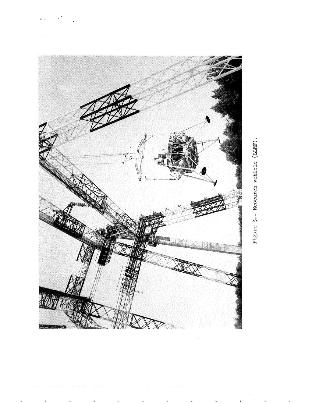
3 lunar environment that would produce true vehicle dynamics. A unique simula- tion facility embodying the capability of producing the dynamics of the T;EM vehicle has been constructed at Langley; flight-test operations using this facility have been in progress since the Spring of The facility depicted in figure 1 consists of a manned rocket powered vehicle suspended by vertical cables from a traveling crane, supported by a gantry structure 25 feet high and 4 feet long. The traveling crane system is servo controlled to follow the vehicle's linear motions and provide lunar gravitational simulation by constantly producing a vertical force acting through the center of gravity of the vehicle equal to five-sixths of its weight. The traveling crane system consists of a bridge structure that travels the length of the gantry and an underslung dolly that travels the width of the bridge. The dolly also contains the hoist system that produces the required cable tension for lunar gravity simulation. The drive for these three linear motions is supplied by servo-controlled hydraulic systems that utilize cable angle sensors as the principal signal for horizontal drive and load measuring cells to constantly maintain the tension in the vertical cables. -_-- -_.I -~..-."" * or,-unar landing research vehicd is attached to the vertical cables by a gimbal system that provides freedom in pitch, roll, and - ~ h e vehicle can be flown with six degrees of freedom in the flight enve- d lope, illustrated in figure 2. The dimensions of the envelope are 36 feet in the down-range X-direction, 42 feet crosswise in the Y-direction, and 18 feet vertically in the Z-direction. Safety features are provided to 2
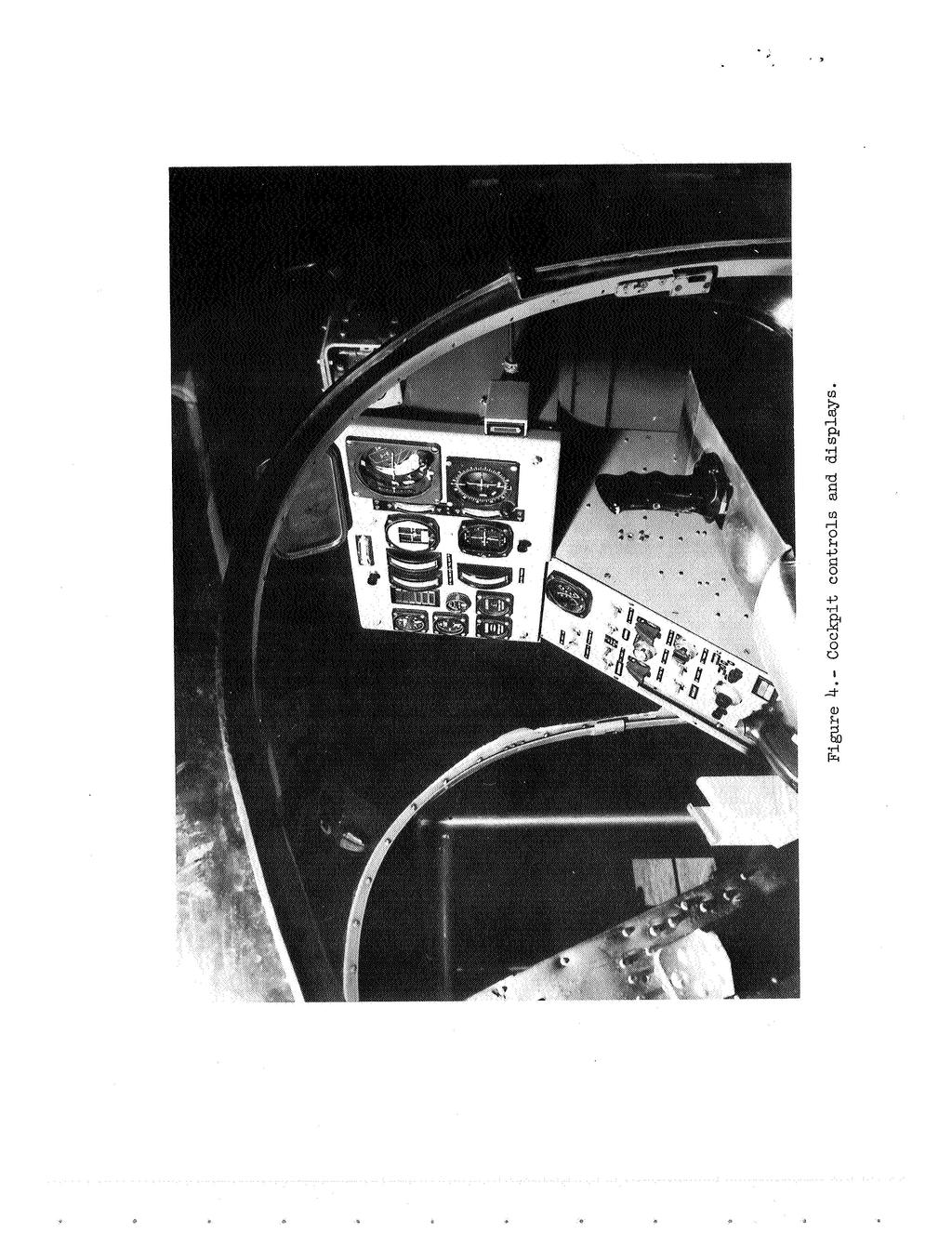
4 prevent the vehicle from exceeding the envelope during either normal or emer- gency operat ion. The manned lunar landing research vehicle (fig. 3) is rocket powered and weighs 12, pounds; including a pilot and 3 pounds of fuel. The vehicle consists of a tubular steel framework that houses a rocket propulsion system with landing gear "oleo" shock struts attached to the four corners. A two-man pilots' compartment and associated control equipment is centrally located on top of the frame. The propulsion system uses 9 percent hydrogen peroxide as a monopropellant and the system is pressurized with gaseous nitrogen. The main motors, located near the bottom of the frame, produce a thrust that can be throttled from 6 to 6 pounds. Twenty smaller rocket motors, each ground adjustable over a range of thrust from 125 to 25 pounds, are distributed about the vehicle frame to produce attitude control torques. Two pilots can be seated, side-by-side in the cockpit shown in figure 4. The pilot flies the vehicle with a LEM type attitude controller, using his right hand, and a throttle control, using his left hand. The attitude con- troller is a three-axis type that comands the control torques about the roll, pitch, and yaw axes in response to appropriate motions of the pilot's wrist and forearm. Throttle control is obtained using the lever which was originally the collective pitch control in the converted helicopter cockpit. This lever is moved up to increase thrust and down to decrease thrust. The flight instru- ments; roll-pitch angle indicator, yaw indicator, altimeter, and angular and linear rate meters are located on the right side of a central display panel. The remainder of the gages are used to monitor vehicle subsystems. These instruments are considered to be those necessary t o fulfill the basic instru- ment display needs for the landing maneuver. 3
5 The vehicle's pitch control system is illustrates schematically in fig- ure 5. The attitude control system for roll and yaw are similar. Control is achieved by the use of torques generated by on-off operation of pairs of the attitude control rockets. The firing signal for these motors is the sum of the pilot command and two'possible signals derived from the vehicle rate gyros. Adjustment of system gains for a given test flight can be made readily by the pilot to select the set of control system test values and the mode of control; that is, acceleration, rate, or attitude command. With gains K1 and K2 set at zero, pilot movement of the controller outside the dead zone fires the motors in an open-loop acceleration command mode. The dead zone can be adjusted to minimize inadvertent control actuation. The motor thrust can be ground adjusted to produce maximum accelerations up to 3 /sec2 in pitch and roll and 17,5/sec2 in yaw. Adjustment of K1 will vary maximum available rates as commanded by the pilot's control from 3 to as low as 5O/sec. The switch dead band can be adjusted to vary the rate at which the system drifts with respect to the command rate. This is the rate command mode where vehicle rate is a direct function of controller displacement. By setting K2, the rate- integral feedback gain, attitude command mode is activated where vehicle atti- tude is a direct function of controller displacement. Throttle or main thrust control as illustrated in figure 5 is operated in an open-loop acceleration command mode. The pilot commands thrust with his control lever through a power-boosted linearized valve. Parameters in this system such as stick sen- sitivity, thrust-to-weight ratio, and stick force gradients are variables that can be studied. The research vehicle and the Apollo LE24 are compared in the drawing in figure 6. The LE24 is slightly larger physically, however, the linear and 4
6 angular accelerations produced by the main and the attitude rockets are com- parable. The flexibility of the research vehicle's control systems and general similarity of the two configurations permits an accurate duplication of the LEN flight characteristics. Consequently, the research vehicle provides the capability of studying in detail the handling qualities required for a lunar landing vehicle, and provides the astronauts with a valuable tool for perfecting their landing techniques with a vehicle that duplicates the dynamics of the LEN. Typical landing trajectories that test pilots have flown are presented in figure 7. In translating and.descending to a landing the pilot uses primarily pitch attitude and throttle control for the respective management of down- range and vertical velocities. Very little use of the roll and yaw controls is made for these straight-in approaches. In an effort to more fully exercise the lateral controls a modified maneuver is frequently utilized. In this maneu- ver the pilot proceeds as if he were going to land, but after having adjusted his velocities for the landing, he performs a 18 turn and translates at reasonably low altitude to perform his landing at the opposite end of the flight envelope. The fuel supply is saficient to allow the pilot a flight the of approximately 2 minutes -to complete this maneuver. The trajectory preferred by most test pilots is the slanting approaches as contrasted to the more nearly vertical. This approach allows the pilot to keep his landing site visible throughout most of the flight and requires little use of instrument displays. The vertical approach is more difficult because the pilot cannot see the landing site and loses his normal motion cues, consequently, he must rely more heavily on instrument displays. 5
7 An example of the pilot's management of his throttle control in a typical translation and descent maneuver, starting at an altitude of about 1 feet, is represented by the solid line in figure 8 which is a plot of vertical velocity versus altitude. In this example, the pilot set up a comfortable rate of descent and apparently concentrated on maintaining it until he reached an altitude of 3 to 4 feet. At this point apparently he could judge his alti- tude with a reasonable degree of accuracy using his visual or out-of-the- window cues and he took on the added task of height or position control. The added task is reflected by an increase in frequency of throttle movement, shown by the velocity reversals in the figure. The boundaries of vertical velocity versus altitude resulting from all the landing approach maneuvers is shown by the dashed line in the figure. After the pilots become experienced and confident with the operation of the throttle, they are comfortable with initial rates of descent up to about 1 ft/sec, and rates of descent at touch- down up to about 4 ft/sec. Pilots utilization of landing velocities up to this touchdown rate eases the landing task by shortening the operating time near the ground. The throttle acceleration command system flown with a stick sensitivity of about.5 lunar "g'src per inch has produced acceptable pilot ratings. Some exploratory investigations have been performed using stick sen- sitivities of one-half to one and one-half the nominal value with little degra- dation of pilot rating. Flight tests performed with various response times of the thrust control from.1 second to about 1.5 seconds have indicated the desirability of response times less than 1. second. The boundaries of translational velocity versus range resulting from the landing approaches, including the turnaround maneuver, is presented as X velocity versus range in figure 9. In performing this task, principally with 6 Y
8 the pitch attitude control, the pilots have generally limited their velocity to about 7.5 ft/sec. Maximum pitch angles of loo to 15' have been utilized in accelerating to and decelerating from this velocity and the corresponding pitch rate has rarely exceeded loo/sec. To date the pilots have not used the large angles that might be expected in accelerating a vehicle with low thrust-to- mass ratio. Instead they have used smaller angles and accepted the longer time required to reach a desired velocity. The attitude control system parameters that have been investigated, principally in the rate command mode, are shown in figure 1 in terms of angular acceleration and maximum available rate. Dead zone, or drift rate, was generally varied as a constant percent of maximum available rate; about.4 /sec at minimum rate to 2.25O/sec at maximum rate. The points plotted at an infi- nite rate represents operation in the acceleration comand mode. The pilot ratings for pitch and roll controls have generally been the same. Accelerations in pitch and roll of 1 /sec2 to 15 /sec2 and lower are characterized by the pilots as smooth, while higher values are described as jerky. There appears to be little requirement for exploring these higher accelerations, inasmuch as the pilots prefer the lower acceleration and the use of higher acceleration will generally result in larger thrusters with an attendant weight increase. Future tests will be run at accelerations of 1/sec2 and below in an attempt to determine the minimum acceptable values. I Maximum pitch and roll rates of 2/sec with an acceleration of 1 /sec2 to 15O/sec* represent the best or most desirable combination that has been found to date. Dead zone, or drift rates, for this combination have been varied from.5o/sec to 2. /sec. The lower drift rate, by virtue of the tightness it gives the system has produced the best pilot rating. Maximum 7
9 available rates in excess of 2/sec are not preferred because of a tendency to overshoot the desired angular displacement, while lower maximum rates are described as requiring too much time to acquire the desired angle. The results for the yaw control system have been quite similar except that a higher maximum available rate has been preferred in those maneuvers requiring large heading change. Utilizing acceleration comand, acceptable pilot ratings have been obtained in a limited number of flight tests. The pilots have, however, experienced difficulty in acquiring smll angular displacements. The following movie illustrates typical flight tests utilizing the Langley Lunar Landing Research Facility. To date we have accumulated flight-test experience with over one hundred flights. The following preliminary conclusions are indicated: 1. The facility provides a useful tool for developing and evaluating flight control systems, and the pilots have been unanimous in their comments with respect to the realism of the simulation. 2. The landing approach can be successfully performed using the unusual control system imposed by the lunar environment. 3. The pilots prefer to fly in a manner similar t o that used in helicop- ters, for example, instead of using the large pitch angles required for com- parable earth translational acceleration, they use smaller pitch angles and accept the longer time required to attain the desired velocity. 4. The facility has indicated a need for and a means of providing pilots and astronauts with flight experience in the dynamics of the lunar landing maneuver. The continuing flight research program will provide additional flying qualities and operational information for lunar landing vehicles. 8
10
11 I N
12 n
13 a
14 I IA
15 h 4-1
16 I I I c n W (3 Z X [R a,.ri k % a, 'r3 cd k +-' M E: ;I 9 rl rl cd 8 I L2 a, 3 ;=I rc, N
17 \ \ \ h 1 a I- LT W > W N
18 3 N I- LL I ro I C - I
19 m - :+- I I I X a z -$pe- ri c s X NASA-Langley, 1966
ACTIVE STICK & THROTTLE FOR F-35. Joseph Krumenacker NAVAIR Flight Controls / JSF Vehicle Systems 16 October 2008
 ACTIVE STICK & THROTTLE FOR F-35 Joseph Krumenacker NAVAIR Flight Controls / JSF Vehicle Systems 16 October 2008 Intro Joe Krumenacker holds a BS in Aerospace & Mechanical Engineering from the University
Application of Steering Robot in the Test of Vehicle Dynamic Characteristics
 3rd International Conference on Mechatronics, Robotics and Automation (ICMRA 2) Application of Steering Robot in the Test of Vehicle Dynamic Characteristics Runqing Guo,a *, Zhaojuan Jiang 2,b and Lin
(12) Patent Application Publication (10) Pub. No.: US 2010/ A1
 Patent Application Publication (10) Pub. No.: US 2010/ A1") (19) United States (12) Patent Application Publication (10) Pub. No.: US 2010/0044499 A1 Dragan et al. US 20100.044499A1 (43) Pub. Date: Feb. 25, 2010 (54) (75) (73) (21) (22) SIX ROTOR HELICOPTER Inventors:
(19) United States (12) Patent Application Publication (10) Pub. No.: US 2010/0044499 A1 Dragan et al. US 20100.044499A1 (43) Pub. Date: Feb. 25, 2010 (54) (75) (73) (21) (22) SIX ROTOR HELICOPTER Inventors:
The most important thing we build is trust. HeliSAS Technical Overview
 The most important thing we build is trust HeliSAS Technical Overview HeliSAS Technical Overview The Genesys HeliSAS is a stability augmentation system (SAS) and two-axis autopilot that provides attitude
Super Squadron technical paper for. International Aerial Robotics Competition Team Reconnaissance. C. Aasish (M.
 Super Squadron technical paper for International Aerial Robotics Competition 2017 Team Reconnaissance C. Aasish (M.Tech Avionics) S. Jayadeep (B.Tech Avionics) N. Gowri (B.Tech Aerospace) ABSTRACT The
APOLLO SPACECRAFT CONTROL SYSTEMS
 ., APOLLO SPACECRAFT CONTROL SYSTEMS by Robert, Chilton.., I. NASA Manned Spacecraft Center Houston, Texas, UIS,A. --. T -. To be Presented at The Symposium on Automatic Control in Peaceful Uses of Space
Performance means how fast will it go? How fast will it climb? How quickly it will take-off and land? How far it will go?
 Performance Concepts Speaker: Randall L. Brookhiser Performance means how fast will it go? How fast will it climb? How quickly it will take-off and land? How far it will go? Let s start with the phase
STICTION/FRICTION IV STICTION/FRICTION TEST 1.1 SCOPE
 Page 1 of 6 STICTION/FRICTION TEST 1.0 STICTION/FRICTION TEST 1.1 SCOPE Static friction (stiction) and dynamic (running) friction between the air bearing surface of sliders in a drive and the corresponding
52 BACKYARDFLYER.COM FLY
 52 BACKYARDFLYER.COM FLY HELIS IN1O EASY STEPS by Klaus Ronge Photography by Hope McCall & Pete Hall Flying model helicopters is exciting and fun and looks very easy, that is, until you try it. Unlike
Review on Handling Characteristics of Road Vehicles
 RESEARCH ARTICLE OPEN ACCESS Review on Handling Characteristics of Road Vehicles D. A. Panke 1*, N. H. Ambhore 2, R. N. Marathe 3 1 Post Graduate Student, Department of Mechanical Engineering, Vishwakarma
Linear Shaft Motors in Parallel Applications
 Linear Shaft Motors in Parallel Applications Nippon Pulse s Linear Shaft Motor (LSM) has been successfully used in parallel motor applications. Parallel applications are ones in which there are two or
Gyroplane questions from Rotorcraft Commercial Bank (From Rotorcraft questions that obviously are either gyroplane or not helicopter)
") Page-1 Gyroplane questions from Rotorcraft Commercial Bank (From Rotorcraft questions that obviously are either gyroplane or not helicopter) "X" in front of the answer indicates the likely correct answer.
Page-1 Gyroplane questions from Rotorcraft Commercial Bank (From Rotorcraft questions that obviously are either gyroplane or not helicopter) "X" in front of the answer indicates the likely correct answer.
Step Motor. Mechatronics Device Report Yisheng Zhang 04/02/03. What Is A Step Motor?
 Step Motor What is a Step Motor? How Do They Work? Basic Types: Variable Reluctance, Permanent Magnet, Hybrid Where Are They Used? How Are They Controlled? How To Select A Step Motor and Driver Types of
Running head: GYROSCOPIC STABILIZATION VS. STABILIZATION FINS 1
 Running head: GYROSCOPIC STABILIZATION VS. STABILIZATION FINS 1 Gyroscopic Stabilization vs. Stabilization fins in Model Rocketry Donald S. Corp, Maccoy G. Merrell Waxahachie Global High School January
CHAPTER 11 FLIGHT CONTROLS
 CHAPTER 11 FLIGHT CONTROLS CONTENTS INTRODUCTION -------------------------------------------------------------------------------------------- 3 GENERAL ---------------------------------------------------------------------------------------------------------------------------
Flight Test Evaluation of C-130H Aircraft Performance with NP2000 Propellers
 Flight Test Evaluation of C-130H Aircraft Performance with NP2000 Propellers Lance Bays Lockheed Martin - C-130 Flight Sciences Telephone: (770) 494-8341 E-Mail: lance.bays@lmco.com Introduction Flight
INTRODUCTION TO HELICOPTER FLYING
 r_helicopter Operations Manual* 7/7/03 4:19 PM Page 2 INTRODUCTION TO HELICOPTER FLYING Flying a helicopter may be a completely new experience for you and we want to ensure that we maximise your enjoyment.
Introducing Galil's New H-Bot Firmware
 March-16 Introducing Galil's New H-Bot Firmware There are many applications that require movement in planar space, or movement along two perpendicular axes. This two dimensional system can be fitted with
XIV.D. Maneuvering with One Engine Inoperative
 References: FAA-H-8083-3; POH/AFM Objectives The student should develop knowledge of the elements related to single engine operation. Key Elements Elements Schedule Equipment IP s Actions SP s Actions
Introduction. 1.2 Hydraulic system for crane operation
 Two control systems have been newly developed for fuel saving in hydraulic wheel cranes: namely, a one-wayclutch system and an advanced engine control system. The former allows one-way transmission of
Analysis and control of vehicle steering wheel angular vibrations
 Analysis and control of vehicle steering wheel angular vibrations T. LANDREAU - V. GILLET Auto Chassis International Chassis Engineering Department Summary : The steering wheel vibration is analyzed through
APPLICATION NOTES VALVE CHECKER M
 APPLICATION NOTES VALVE CHECKER M040-120-001 1 of 16 CONTENTS Chapter Title Page 1. Description 3 2. Specification 7 3. Connecting to valve and plant 8 4. Plant mode operation (in line) 9 5. Checker mode
Application Note Original Instructions Development of Gas Fuel Control Systems for Dry Low NOx (DLN) Aero-Derivative Gas Turbines
 Aero-Derivative Gas Turbines") Application Note 83404 Original Instructions Development of Gas Fuel Control Systems for Dry Low NOx (DLN) Aero-Derivative Gas Turbines Woodward reserves the right to update any portion of this publication
Application Note 83404 Original Instructions Development of Gas Fuel Control Systems for Dry Low NOx (DLN) Aero-Derivative Gas Turbines Woodward reserves the right to update any portion of this publication
Impact, Torsion, and Crush Tests for 477 kcmil and 795 kcmil 3M Brand Composite Conductor. 3M Company Purchase Order
 Impact, Torsion, and Crush Tests for 477 kcmil and 795 kcmil 3M Brand Composite Conductor 3M Company Purchase Order 0000620410 NEETRAC Project Number: 02-229 October, 2002 A Center of The Georgia Institute
How to use the Multirotor Motor Performance Data Charts
 How to use the Multirotor Motor Performance Data Charts Here at Innov8tive Designs, we spend a lot of time testing all of the motors that we sell, and collect a large amount of data with a variety of propellers.
three different ways, so it is important to be aware of how flow is to be specified
 Flow-control valves Flow-control valves include simple s to sophisticated closed-loop electrohydraulic valves that automatically adjust to variations in pressure and temperature. The purpose of flow control
Active Control of Sheet Motion for a Hot-Dip Galvanizing Line. Dr. Stuart J. Shelley Dr. Thomas D. Sharp Mr. Ronald C. Merkel
 Active Control of Sheet Motion for a Hot-Dip Galvanizing Line Dr. Stuart J. Shelley Dr. Thomas D. Sharp Mr. Ronald C. Merkel Sheet Dynamics, Ltd. 1776 Mentor Avenue, Suite 17 Cincinnati, Ohio 45242 Active
FLIGHT CONTROLS SYSTEM
 FLIGHT CONTROLS SYSTEM DESCRIPTION Primary flight control of the aircraft is provided by aileron, elevator and rudder control surfaces. The elevator and rudder control surfaces are mechanically operated.
Extremely High Load Capacity Tapered Roller Bearings
 New Product Extremely High Load Capacity Tapered Roller Bearings Takashi UENO Tomoki MATSUSHITA Standard tapered roller bearing Extreme high load capacity bearing NTN developed a tapered roller bearing
Electric Drive - Magnetic Suspension Rotorcraft Technologies
 Electric Drive - Suspension Rotorcraft Technologies William Nunnally Chief Scientist SunLase, Inc. Sapulpa, OK 74066-6032 wcn.sunlase@gmail.com ABSTRACT The recent advances in electromagnetic technologies
First Civilian Tiltrotor Takes Flight
 The MathWorks Aerospace & Defense Conference Reston, Virginia June 14-15, 15, 2006 First Civilian Tiltrotor Takes Flight 200608-1 David King Bell Helicopter BA609 Analytical Integration Leader RESTRICTED
Important Notes Note Recommended Equipment NOT included in kit
 Important Notes This helicopter is recommended for skilled intermediates and advanced RC helicopter flyers. Make sure to read and follow all the instructions in this manual, including all accessories.
EMERGENCY PROCEDURES SECTION I. HELICOPTER SYSTEMS
 9-1. HELICOPTER SYSTEMS. EMERGENCY PROCEDURES SECTION I. HELICOPTER SYSTEMS This section describes the helicopter systems emergencies that may reasonably be expected to occur and presents the procedures
INDEX. Preflight Inspection Pages 2-4. Start Up.. Page 5. Take Off. Page 6. Approach to Landing. Pages 7-8. Emergency Procedures..
 INDEX Preflight Inspection Pages 2-4 Start Up.. Page 5 Take Off. Page 6 Approach to Landing. Pages 7-8 Emergency Procedures.. Page 9 Engine Failure Pages 10-13 Propeller Governor Failure Page 14 Fire.
Airframes Instructor Training Manual. Chapter 6 UNDERCARRIAGE
 Learning Objectives Airframes Instructor Training Manual Chapter 6 UNDERCARRIAGE 1. The purpose of this chapter is to discuss in more detail the last of the Four Major Components the Undercarriage (or
It has taken a while to get
 HOVERING15 99 15 BASICS HOVERING Hovering It has taken a while to get here, but this is what all the building and planning were for to see light under those skids. But this is also the time when you have
Compliance Checklist. 1 of 9. Legend: A-analysis, C-comparison, D-design, T-test FAR Amdt. Compliance Method Takeoff. Description
 Compliance Checklist Legend: A-analysis, C-comparison, -design, -test FAR Amdt. Compliance Method akeoff. escription 27.51 C, (a) he takeoff, with takeoff power and r.p.m., and with the extreme forward
Performance Evaluation of a Side Mounted Shuttle Derived Heavy Lift Launch Vehicle for Lunar Exploration
 Performance Evaluation of a Side Mounted Shuttle Derived Heavy Lift Launch Vehicle for Lunar Exploration AE8900 MS Special Problems Report Space Systems Design Lab (SSDL) School of Aerospace Engineering
1.1 REMOTELY PILOTED AIRCRAFTS
 CHAPTER 1 1.1 REMOTELY PILOTED AIRCRAFTS Remotely Piloted aircrafts or RC Aircrafts are small model radiocontrolled airplanes that fly using electric motor, gas powered IC engines or small model jet engines.
Development of Feedforward Anti-Sway Control for Highly efficient and Safety Crane Operation
 7 Development of Feedforward Anti-Sway Control for Highly efficient and Safety Crane Operation Noriaki Miyata* Tetsuji Ukita* Masaki Nishioka* Tadaaki Monzen* Takashi Toyohara* Container handling at harbor
Cessna Aircraft Short & Soft Field Takeoff & Landing Techniques
 Cessna Aircraft Short & Soft Field Takeoff & Landing Techniques Objectives / Content For short- and soft-field takeoff and landing operations in CAP Cessna aircraft, review: Standards (from ACS) Procedures
INSTALLATION MANUAL AND OPERATING INSTRUCTIONS Electric Attitude Indicator
 INSTALLATION MANUAL AND OPERATING INSTRUCTIONS 4200-21 Electric Attitude Indicator Mid-Continent Instruments and Avionics Manual Number 9016182-1 9400 E 34 th Street N, Wichita, KS 67226 USA Revision D,
A COMPARISON OF THE PERFORMANCE OF LINEAR ACTUATOR VERSUS WALKING BEAM PUMPING SYSTEMS Thomas Beck Ronald Peterson Unico, Inc.
 A COMPARISON OF THE PERFORMANCE OF LINEAR ACTUATOR VERSUS WALKING BEAM PUMPING SYSTEMS Thomas Beck Ronald Peterson Unico, Inc. ABSTRACT Rod pumping units have historically used a crank-driven walking beam
Liberty Aerospace, Inc. Section 1 SECTION 1 GENERAL TABLE OF CONTENTS
 Liberty Aerospace, Inc. Section 1 SECTION 1 TABLE OF CONTENTS Introduction... 1-3 Airplane Three Views... 1-4 Descriptive Data... 1-5 Engine... 1-5 Propeller... 1-5 Fuel... 1-5 Oil... 1-5 Maximum Certificated
Study on Mechanism of Impact Noise on Steering Gear While Turning Steering Wheel in Opposite Directions
 Study on Mechanism of Impact Noise on Steering Gear While Turning Steering Wheel in Opposite Directions Jeong-Tae Kim 1 ; Jong Wha Lee 2 ; Sun Mok Lee 3 ; Taewhwi Lee 4 ; Woong-Gi Kim 5 1 Hyundai Mobis,
International Journal of Scientific & Engineering Research, Volume 4, Issue 7, July ISSN BY B.MADHAN KUMAR
 International Journal of Scientific & Engineering Research, Volume 4, Issue 7, July-2013 485 FLYING HOVER BIKE, A SMALL AERIAL VEHICLE FOR COMMERCIAL OR. SURVEYING PURPOSES BY B.MADHAN KUMAR Department
THE INSTITUTE OF PAPER CHEMISTRY, APPLETON, WISCONSIN
 THE INSTITUTE OF PAPER CHEMISTRY, APPLETON, WISCONSIN HIGH SPEED PHOTOGRAPHY OF THE DISK REFINING PROCESS Project 2698 Report 5 To The Technical Division Fourdrinier Kraft Board Group of the American Paper
VERT 1 VERTICAL TAKE OFF / LANDING RC PLANE
 VERT 1 VERTICAL TAKE OFF / LANDING RC PLANE THANK YOU. Thank you for your purchase of Protocol s Vert I Vertical Take Off / Landing RC Plane. You are about to experience the best of what remote control
Flight Readiness Review Addendum: Full-Scale Re-Flight. Roll Induction and Counter Roll NASA University Student Launch.
 Flight Readiness Review Addendum: Full-Scale Re-Flight Roll Induction and Counter Roll 2016-2017 NASA University Student Launch 27 March 2017 Propulsion Research Center, 301 Sparkman Dr. NW, Huntsville
AERONAUTICAL DESIGN STANDARD PERFORMANCE SPECIFICATION HANDLING QUALITIES REQUIREMENTS FOR MILITARY ROTORCRAFT
 INCH-POUND 21 March 2000 CAGE Code 18876 SUPERSEDING ADS-33D-PRF 10 May 1996 AERONAUTICAL DESIGN STANDARD PERFORMANCE SPECIFICATION HANDLING QUALITIES REQUIREMENTS FOR MILITARY ROTORCRAFT AMSC N/A DISTRIBUTION
Reducing Landing Distance
 Reducing Landing Distance I've been wondering about thrust reversers, how many kinds are there and which are the most effective? I am having a debate as to whether airplane engines reverse, or does something
Active Systems Design: Hardware-In-the-Loop Simulation
 Active Systems Design: Hardware-In-the-Loop Simulation Eng. Aldo Sorniotti Eng. Gianfrancesco Maria Repici Departments of Mechanics and Aerospace Politecnico di Torino C.so Duca degli Abruzzi - 10129 Torino
Deployment and Flight Test of Inflatable Membrane Aeroshell using Large Scientific Balloon
 1 Deployment and Flight Test of Inflatable Membrane Aeroshell using Large Scientific Balloon Kazuhiko Yamada, Takashi Abe (JAXA/ISAS) Kojiro Suzuki, Naohiko Honma, Yasunori Nagata, Masashi Koyama (The
Vehicle Dynamics and Drive Control for Adaptive Cruise Vehicles
 Vehicle Dynamics and Drive Control for Adaptive Cruise Vehicles Dileep K 1, Sreepriya S 2, Sreedeep Krishnan 3 1,3 Assistant Professor, Dept. of AE&I, ASIET Kalady, Kerala, India 2Associate Professor,
AIRCRAFT GENERAL KNOWLEDGE (2) INSTRUMENTATION
 INSTRUMENTATION") 1 The purpose of the vibrating device of an altimeter is to: A reduce the effect of friction in the linkages B inform the crew of a failure of the instrument C allow damping of the measurement in the unit
1 The purpose of the vibrating device of an altimeter is to: A reduce the effect of friction in the linkages B inform the crew of a failure of the instrument C allow damping of the measurement in the unit
Bus Handling Validation and Analysis Using ADAMS/Car
 Bus Handling Validation and Analysis Using ADAMS/Car Marcelo Prado, Rodivaldo H. Cunha, Álvaro C. Neto debis humaitá ITServices Ltda. Argemiro Costa Pirelli Pneus S.A. José E. D Elboux DaimlerChrysler
FRONTAL OFF SET COLLISION
 FRONTAL OFF SET COLLISION MARC1 SOLUTIONS Rudy Limpert Short Paper PCB2 2014 www.pcbrakeinc.com 1 1.0. Introduction A crash-test-on- paper is an analysis using the forward method where impact conditions
HELICOPTER TAIL ROTOR ANALYSIS: EXPERIENCE IN AGUSTA WITH ADAMS
 HELICOPTER TAIL ROTOR ANALYSIS: EXPERIENCE IN AGUSTA WITH ADAMS Bianchi F., Agusta Sp.a. Via G.Agusta, 520 - Cascina Costa di Samarate,Varese - Italy - e-mail: atr@agusta.it Abstract The purpose of the
The design of the Kolibri DVD-actuator.
 The design of the Kolibri DVD-actuator. F.G.A. Homburg. Philips Optical Storage Optical Recording Development. 21-10-1998 VVR-42-AH-98004 Introduction. In any optical drive a laser beam is focused on to
SAE Mini BAJA: Suspension and Steering
 SAE Mini BAJA: Suspension and Steering By Zane Cross, Kyle Egan, Nick Garry, Trevor Hochhaus Team 11 Progress Report Submitted towards partial fulfillment of the requirements for Mechanical Engineering
Physics 12 Circular Motion 4/16/2015
 Circular Motion Name: 1. It is possible to spin a bucket of water in a vertical circle and have none of the water spill when the bucket is upside down. How would you explain this to members of your family?
AVIATOR REMOTE CONTROL HELICOPTER
 AVIATOR REMOTE CONTROL HELICOPTER THANK YOU. Thank you for your purchase of Protocol s Aviator Remote Control Helicopter. You are about to experience the best of what remote control flight has to offer.
MGA Research Corporation
 MGA Research Corporation Real Time Simulation Testing Gerald Roesser David Nagle Thomas Hutter MGA Research Corporation 1 MGA Research Corporation PRESENTERS Gerald Roesser BSEE MGA Associate since 2001
Performance evaluation for various braking systems of street motorcycles
 Performance evaluation for various braking systems of street motorcycles Introduction This report covers a series of motorcycle braking tests aimed at measuring the performance of the front brake and of
INSTALLATION MANUAL AND OPERATING INSTRUCTIONS XX and XX Series Electric Attitude Indicator
 INSTALLATION MANUAL AND OPERATING INSTRUCTIONS 4300-3XX and 4300-5XX Series Electric Attitude Indicator MID-CONTINENT INST. CO., INC MANUAL NUMBER 9015692 Copyright 2003 Mid-Continent Instrument Co., Inc.
RESEARCH MEMORANDUM. fox the. U. S. Air Force
 RESEARCH MEMORANDUM fox the U. S. Air Force - NACA RM SL53L24 NATIONAL ADVISORY COMMITTEE FOR AERONAIJTICS RESEARCH "ORANDUM the for U. S. Air Force _.I SPEED-BRAKE INVESTIGATION AT LOW SPEEDOF A l/lo-scale
XIV.C. Flight Principles Engine Inoperative
 XIV.C. Flight Principles Engine Inoperative References: FAA-H-8083-3; POH/AFM Objectives The student should develop knowledge of the elements related to single engine operation. Key Elements Elements Schedule
Figure1: Kone EcoDisc electric elevator drive [2]
![Figure1: Kone EcoDisc electric elevator drive [2]](/thumbs/77/75088735.jpg "Figure1: Kone EcoDisc electric elevator drive [2]") Implementation of an Elevator s Position-Controlled Electric Drive 1 Ihedioha Ahmed C. and 2 Anyanwu A.M 1 Enugu State University of Science and Technology Enugu, Nigeria 2 Transmission Company of Nigeria
Implementation of an Elevator s Position-Controlled Electric Drive 1 Ihedioha Ahmed C. and 2 Anyanwu A.M 1 Enugu State University of Science and Technology Enugu, Nigeria 2 Transmission Company of Nigeria
Stopping Accuracy of Brushless
 Stopping Accuracy of Brushless Features of the High Rigidity Type DGII Series Hollow Rotary Actuator The DGII Series hollow rotary actuator was developed for positioning applications such as rotating a
Autonomous Quadrotor for the 2014 International Aerial Robotics Competition
 Autonomous Quadrotor for the 2014 International Aerial Robotics Competition Yongseng Ng, Keekiat Chua, Chengkhoon Tan, Weixiong Shi, Chautiong Yeo, Yunfa Hon Temasek Polytechnic, Singapore ABSTRACT This
CONTENTS Duct Jet Propulsion / Rocket Propulsion / Applications of Rocket Propulsion / 15 References / 25
 CONTENTS PREFACE xi 1 Classification 1.1. Duct Jet Propulsion / 2 1.2. Rocket Propulsion / 4 1.3. Applications of Rocket Propulsion / 15 References / 25 2 Definitions and Fundamentals 2.1. Definition /
The Deployable Gage Restraint Measurement System - Description and Operational Performance
 The Deployable Gage Restraint Measurement System - Description and Operational Performance GARY A. MARTIN ENSCO, INC 5400 PORT ROYAL ROAD SPRINGFIELD, VA 22151 703-321-4513 703-321-7619 (FAX) JEFFREY A.
(12) Patent Application Publication (10) Pub. No.: US 2006/ A1
 Patent Application Publication (10) Pub. No.: US 2006/ A1") US 20060226281A1 (19) United States (12) Patent Application Publication (10) Pub. No.: Walton (43) Pub. Date: Oct. 12, 2006 (54) DUCTED FAN VERTICAL TAKE-OFF AND (52) U.S. Cl.... 244f1723 LANDING VEHICLE
US 20060226281A1 (19) United States (12) Patent Application Publication (10) Pub. No.: Walton (43) Pub. Date: Oct. 12, 2006 (54) DUCTED FAN VERTICAL TAKE-OFF AND (52) U.S. Cl.... 244f1723 LANDING VEHICLE
time in seconds Amy leaves diving board
 1 Amy dives from the high diving board at a swimming pool. Look at the graph of her motion. speed in m / s 15 10 Amy enters water P Q 5 0 0 0.5 1.0 1.5 2.0 2.5 time in seconds Amy leaves diving board (a)
Tech Tip: Trackside Tire Data
 Using Tire Data On Track Tires are complex and vitally important parts of a race car. The way that they behave depends on a number of parameters, and also on the interaction between these parameters. To
MULTIBODY ANALYSIS OF THE M-346 PILOTS INCEPTORS MECHANICAL CIRCUITS INTRODUCTION
 MULTIBODY ANALYSIS OF THE M-346 PILOTS INCEPTORS MECHANICAL CIRCUITS Emanuele LEONI AERMACCHI Italy SAMCEF environment has been used to model and analyse the Pilots Inceptors (Stick/Pedals) mechanical
Tom Parece, Reggie Donoghue and Mike Domenica P. R. Ammann
 To: From: Subject: Tom Parece, Reggie Donoghue and Mike Domenica P. R. Ammann TM #7 A STEP Effluent Has a Big Cost Advantage over a Gravity for Downtown Orleans Date: January 12, 2017 Summary In its preliminary
HYDRAULIC ACTUATOR REPLACEMENT USING ELECTROMECHANICAL TECHNOLOGY
 HYDRAULIC ACTUATOR REPLACEMENT USING ELECTROMECHANICAL TECHNOLOGY SCOPE This white paper discusses several issues encountered by Lee Air with past projects that involved the replacement of Hydraulic Actuators
SPMM OUTLINE SPECIFICATION - SP20016 issue 2 WHAT IS THE SPMM 5000?
 SPMM 5000 OUTLINE SPECIFICATION - SP20016 issue 2 WHAT IS THE SPMM 5000? The Suspension Parameter Measuring Machine (SPMM) is designed to measure the quasi-static suspension characteristics that are important
Introduction: Problem statement
 Introduction: Problem statement The goal of this project is to develop a catapult system that can be used to throw a squash ball the farthest distance and to be able to have some degree of accuracy with
DRIVING STABILITY OF A VEHICLE WITH HIGH CENTRE OF GRAVITY DURING ROAD TESTS ON A CIRCULAR PATH AND SINGLE LANE-CHANGE
 Journal of KONES Powertrain and Transport, Vol. 1, No. 1 9 DRIVING STABILITY OF A VEHICLE WITH HIGH CENTRE OF GRAVITY DURING ROAD TESTS ON A CIRCULAR PATH AND SINGLE LANE-CHANGE Kazimierz M. Romaniszyn
'Prototype' Commission Regulation on Unmanned Aircraft Operations. FAI proposal for model flying activities
 Lausanne, 17 January 2017 'Prototype' Commission Regulation on Unmanned Aircraft Operations FAI proposal for model flying activities Annexes: 1- Article 15 - Provisions for model aircraft operations 2-
44xx Estes-Cox Corp H Street, PO Box 227 Penrose, CO Made In Shantou, Guangdong, China
 Do not turn on the Proto-N unless controller has been turned on fi rst. Keep hands, hair and loose clothing away from spinning blades. Turn off controller and Proto-N when not in use. Parental guidance
Artemis: A Reusable Excursion Vehicle Concept for Lunar Exploration
 Artemis: A Reusable Excursion Vehicle Concept for Lunar Exploration David A. Young *, John R. Olds, Virgil Hutchinson *, Zachary Krevor *, James Young * Space Systems Design Lab Guggenheim School of Aerospace
AERO. Meet the Aero. Congratulations on your purchase of an Aero!
 AERO Congratulations on your purchase of an Aero! Please read the following sections of this manual to get started with your new autonomous aircraft. 1 Meet the Aero 7 Fly-by-wire mode 2 Safety 8 Command
Section 2: Basic Aerobatics
 Section 2: Basic Aerobatics Airplane Considerations and Control Setup Primary to Aerobatic Airplane Transition Parallel Positioning B-34 Basic Aerobatics Introduction Aerobatics is unarguably the most
Weight & Balance. Let s Wait & Balance. Chapter Sixteen. Page P1. Excessive Weight and Structural Damage. Center of Gravity
 Page P1 Chapter Sixteen Weight & Balance Let s Wait & Balance Excessive Weight and Structural Damage 1. [P2/1/1] Airplanes are designed to be flown up to a specific maximum weight. A. landing B. gross
Increase your Productivity with Hydraulic Mold Oscillation Systems in Continuous Casting Machines
 Increase your Productivity with Hydraulic Mold Oscillation Systems in Continuous Casting Machines 2 Producing High-quality Steel More Precisely, Efficiently and Sustainedly The demands made on new, heavy-duty
MASSACHUSETTS INSTITUTE OF TECHNOLOGY Department of Aeronautics and Astronautics
 MASSACHUSETTS INSTITUTE OF TECHNOLOGY Department of Aeronautics and Astronautics 16.00 Introduction to Aerospace and Design Problem Set #4 Issued: February 28, 2002 Due: March 19, 2002 ROCKET PERFORMANCE
NOTICE. The above identified patent application is available for licensing. Requests for information should be addressed to:
 Serial Number 045.963 Filing Date 18 March 1998 Inventor Michael W. Williams James B. Walsh NOTICE The above identified patent application is available for licensing. Requests for information should be
FEASIBILITY STYDY OF CHAIN DRIVE IN WATER HYDRAULIC ROTARY JOINT
 FEASIBILITY STYDY OF CHAIN DRIVE IN WATER HYDRAULIC ROTARY JOINT Antti MAKELA, Jouni MATTILA, Mikko SIUKO, Matti VILENIUS Institute of Hydraulics and Automation, Tampere University of Technology P.O.Box
Cam Motion Case Studies #1 and # 2
 Cam Motion Case Studies #1 and # 2 Problem/Opprtunity: At an operating speed of 150 to 160 rpm, Cam Motion #1 causes the cam follower to leave the cam surface unless excessive air pressure is applied to
Skycar Flight Control System Overview By Bruce Calkins August 14, 2012
 Skycar Flight Control System Overview By Bruce Calkins August 14, 2012 Introduction The Skycar is a new type of personal aircraft that will rely on directed thrust produced by its engines to enable various
Mercury VTOL suas Testing and Measurement Plan
 Mercury VTOL suas Testing and Measurement Plan Introduction Mercury is a small VTOL (Vertical Take-Off and Landing) aircraft that is building off of a quadrotor design. The end goal of the project is for
Fly Me To The Moon On An SLS Block II
 Fly Me To The Moon On An SLS Block II Steven S. Pietrobon, Ph.D. 6 First Avenue, Payneham South SA 5070, Australia steven@sworld.com.au Presented at International Astronautical Congress Adelaide, South
Simulation of Influence of Crosswind Gusts on a Four Wheeler using Matlab Simulink
 Simulation of Influence of Crosswind Gusts on a Four Wheeler using Matlab Simulink Dr. V. Ganesh 1, K. Aswin Dhananjai 2, M. Raj Kumar 3 1, 2, 3 Department of Automobile Engineering 1, 2, 3 Sri Venkateswara
SECTION 3 EMERGENCY PROCEDURES CONTENTS
 CONTENTS Page Definitions.................................. 3-1 Power Failure - General......................... 3-1 Power Failure Above 500 feet AGL................ 3-2 Power Failure Between 8 and 500
Station for Exploratory Analysis and Research Center for Humanity (SEARCH)
") Station for Exploratory Analysis and Research Center for Humanity (SEARCH) Authors: Jasmine Wong, Matthew Decker, Joseph Lewis, Megerditch Arabian, and Dr. Peter Bishay California State University, Northridge
Station for Exploratory Analysis and Research Center for Humanity (SEARCH) Authors: Jasmine Wong, Matthew Decker, Joseph Lewis, Megerditch Arabian, and Dr. Peter Bishay California State University, Northridge
Session 5 Wind Turbine Scaling and Control W. E. Leithead
 SUPERGEN Wind Wind Energy Technology Session 5 Wind Turbine Scaling and Control W. E. Leithead Supergen 2 nd Training Seminar 24 th /25 th March 2011 Wind Turbine Scaling and Control Outline Introduction
Chapter 4. Vehicle Testing
 Chapter 4 Vehicle Testing The purpose of this chapter is to describe the field testing of the controllable dampers on a Volvo VN heavy truck. The first part of this chapter describes the test vehicle used