TM215 Suzuki 9.9 & 15 HP 2014 to Present Tiller and Remote Shift and Throttle Motors
|
|
|
- Hugh Tyler
- 6 years ago
- Views:
Transcription


1 TM215 Suzuki 9.9 & 15 HP 2014 to Present Tiller and Remote Shift and Throttle Motors TrollMaster is a precision throttle control designed to achieve the maximum in trolling speed accuracy. The memory feature included in this control will allow returning to the best fishing speed time and time again. Whether you are pulling your bait or back trolling, TrollMaster is the answer to your speed control needs. Spend your time trolling, not going to the motor to adjust the speed. PH: info@marinetechproducts.com MAIL: - NEW$ADDRESS$AS$OF$MARCH$1ST,$2013$$ MARINETECH PRODUCTS, INC. TROLLMASTER 1360 EAST COUNTY ROAD E VADNAIS HEIGHTS, MN 55110

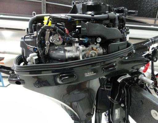
2 Step%1:%% Instruction%for%Tiller%motors%only.% LoosentheTillerArmtensioncontrolknoballthewaysothetillergripcanmovefreely. Step%2:%% Removetheenginecowling.
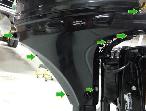
3 Step%2%continued:% Instruction%for%Remote%Shift%and%Throttle%motors%only,%Tiller%motors%DO%NOT%need%to%remove% this%side%cover.% Removethesidecoverbyremovingthescrewsindicatedbelow. Andremovethecowling srearlatchpinandlatch.

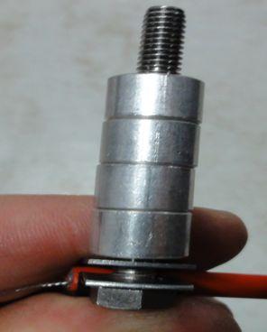
4 Step%3:%% Installthefirstcablemountcliptotheorangecableshield.Pleasenote:besuretheorange cableshieldisnearlyflushwiththecablemountclipbeforesqueezingitclosedaroundthe cableshield.seephotoforexample. Step%4:%% AddtheboltandfourspacersprovidedintheTrollMasterkitandinstallasshown.


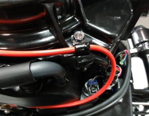
5 Step%5:%% RemovefactoryboltandinstallTrollMasterbolt,spacersandcableasshownbelow.Please% note:thetwophotosonthispageareofthe RemoteShiftandThrottle versionofthismotor, notthetiller.thisphotoismeanttoshowthecablemountasitshouldlookwheninstalledon boththetillerandremoteshiftandthrottlemotors. Step%6:%% Attachcableloopasshown.% %
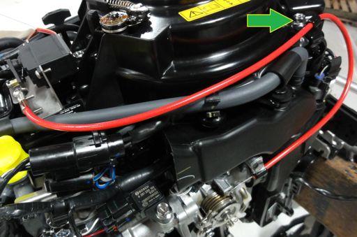
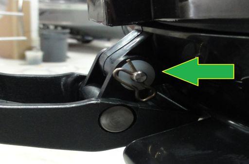
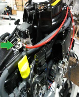
6 Step%7:%% Usingthefactorybolt,mountthesecondcableclampontheboltidentifiedbythegreenarrow inthephoto.
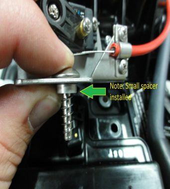
7 Step%8:%% Mounttheservobracketasshownusingthefactoryscrewandsmallspacerprovidedinthe TrollMasterkit.Please%note:Makesurethesmallspacerisinstalledundertheservobracket beforetighteningscrew.

8 % % Step%9:%% Besuretheservoarmisinthepositionshowninthephotos,ifitisnot,plugtheservointothe greycontrolcable,powerthetrollmastercontrolleronandleaveitinidlemode.byremoving thephillipsheadscrewthatholdstheservoarmontheservobodyyoucanremovetheservo armbypullingitoffoftheservobody,donottwistandpull,justpullitstraightoff.adjustthe servoarmtobeinthepositionasshownintheinstallationmanualphotos,placetheservoarm backontheservobodyandreturnthephillipsheadscrewtoitsoriginallocationtoholdthe servoarminplace. RemovePhilipsheadsetscrewfromthebrassbarrelontheservoarmasshown.Youwillnot needthephilipsheadsetscrewinthebrassbarrelforthisinstall.runthecablethroughthe brassbarrelbutdonotcrimpityet.% %


9 % Step%10:% Withthethrottleclosed,pullthecabletighttoremoveanyslack,besurethethrottleremains closed.whenthecableistight,slidethecrimpoverthecableandcrimpittightasshowninthe photo.youcanthencutofftheexcesscable. Step%11:%% Instruction%for%Remote%Shift%and%Throttle%motors%only.% Removethefactorycambyfirstremovingtherodandwhiterodretainerfromthefactorycam. %


10 Step%12:%% Instruction%for%Remote%Shift%and%Throttle%motors%only.% Removethefactorycambyremovingthebolt;besurethecamassemblydoesnotcomeoffthe motorwhenremovingthebolt.% % % Step%13:%% Instruction%for%Remote%Shift%and%Throttle%motors%only.% InstalltheTrollMastercamandreinstallthefactoryrod&rodretainerasshownbelow.
11 Connecting to a power source: Connect the Red wire to +12 volts DC and the Black wire to -12 volts DC. PRO and PRO2 models come with three (3) amp fuses and PRO3 models come with a thirty (30) amp fuse. Connecting the servo: Connect the servo cable to the control cable with the brown wire aligned to the white mark on the control cable plug, if you have a lockable connector be sure the lock is engaged. After plugging in your servo motor test it to ensure proper function. Testing the controller: You do not have to run your outboard motor to test the TrollMaster. Test the controller by powering the unit on and press the IDLE button to put the unit into RUN mode. By turning the control knob with a clockwise rotation the servo should move the carburetor from IDLE to FULL THROTTLE. NOTE: Full throttle can be adjusted by changing the position of the servo arm on the servo motor. So if the servo motor wants to open your throttle too much, adjust the servo arm so there is slack in the linkage when in IDLE mode, that will keep the throttle from opening too far.
12 Troubleshooting If you should encounter an issue with your TrollMaster use these tips to determine the best course of action to resolve the issue. Problem: The unit powers on and the display functions properly, your buttons show function on the screen and the numbers increase when turning the speed adjustment knob but there is no response from the servo motor. Solution: Verify the servo motor is plugged in accordingly with the brown wire aligned with the white mark on the control cable plug or that the lockable connector is locked in position and test again. If there is still no response, replace the servo motor with a new one and test again. If after replacing the servo motor and testing again there is still no response contact MarineTech Products Inc to have the unit inspected at our facility. Problem: The unit powers on works momentarily then powers off. The unit will not stay powered on. Solution: Check your battery voltage; if the battery voltage is low the unit will not operate properly. When in doubt charge your battery to ensure there is enough voltage to operate the TrollMaster unit to its fullest potential. If the battery is fully charged and the unit is still not operating properly contact MarineTech Products, Inc to have the unit inspected at our facility. If you need assistance with Troubleshooting contact MarineTech Products, Inc. Call
13 TrollMaster Replacement Parts TrollMaster Servo Motor (TM-MG1) Note: A Servo Arm is included with the purchase of a replacement Servo Motor. TrollMaster Servo Arm (TM-Servo Arm) Note: A replacement screw to mount the Servo Arm to the Servo Body is included with the purchase of a replacement Servo Arm. TrollMaster Hardware Kit (TMXXXHRDWRKIT) Note: Replace the XXX with the Kit number that applies to your outboard motor. See the Application Guide for kit number. Example: TM206HRDWRKIT. TrollMaster Electronics Unit Only (TMXXXXUNITONLY) Note: Replace the XXXX with the model of Replacement TrollMaster Electronics you wish to purchase. Comes with controller and wiring only, does not include servo motor or hardware kit. Examples: TMPROUNITONLY, TMPRO2UNITONLY, TMPRO3UNITONLY. To Order Replacement Parts: If you would like to order any of the above mentioned replacement parts check with your local retailer, if they do not have the item in stock they can order it for you or you can order directly from MarineTech Products, Inc. For pricing and availability call MarineTech Products, Inc Installation Guides: The installation Guide on this disk can also be found online at MarineTech Products website, visit: and follow the TrollMaster link to the TrollMaster page where you will find the Installation Guides for every motor we make a kit to fit. The Application Guide is also on the same web page; the Application Guide shows the full list of motors we make kits to fit with the product part numbers for those kits.
14 SERVICE%AND%WARRANTY Shouldyouruniteverrequireservicepleasedo#not#return#the#product#to#your#dealer.#Insteadcallthe numberbelowforspecialinstructionsonshippingandhandling.besuretocallbetween900amand 4.00PM(CentralTime)MondaythroughFriday.Iftheservicerequirediscoveredbythewarranty,itwill berepairedorreplacedasdescribedbelow.iftheservicerequiredisnotcoveredbywarranty replacementpartsareavailableforpurchaseandpaidforbyamajorcreditcard. Thewarrantycoverageonthisequipmentislimitedtothetermssetforthbelow: MarineTechProducts,Inc.warrantsthisproducttobefreeofdefectsinmaterialandworkmanshipfora periodofone(1)yearfromthedateoforiginalretailpurchase.positiveproofofdateofpurchaseis requiredforwarrantyservice.iftheservicerequirediscoveredbywarranty,youmust#obtainareturn# Authorization#numberfromMarineTechProducts.Theunitwillberepairedorreplacedwithnewor factoryrebuiltpartsatnocharge.thedefectivecomponentsmusthereturnedtotheaddressspecified, withshippingchargesprepaid.besuretoincludeyourname,address,telephonenumberandacopyof thesalesreceiptshowingthedateoforiginalretailpurchase.allsalesreceiptsaresubjectto verification. Thiswarrantydoesnotapplyiftheunithasbeendamagedbyaccident,abuse,misuse,poorinstallation ormisapplication,orifithasbeenmodifiedfromitsoriginalcondition,orifanyserialnumberhasbeen removedordefacedoraltered.thiswarrantydoesnotcoveranyexpensetoremoveorreinstalltheunit oranyofitscomponents.ifareturnedunitisnotcoveredbywarranty,thesenderwillhenotifiedand givenanestimateofthechargestorepairorreplacetheunittogetherwiththereturnshippingcharges. THISWARRANTYDOESNOTCOVERSPECIAL,INCIDENTAL,ORCONSEQUENTIALDAMAGESRESULTING FROMANYBREACHOFWARRANTY,ORUNDERANYOTHERLEGALTHEORY,INCLUDINGBUTNOT LIMITEDTODAMAGETOORREPLACEMENTOFOTHEREQUIPMENTANDPROPERTY.THEWARRANTY ANDREMEDIESSETFORTHAREEXCLUSIVEANDINLIEUOFALLOTHERS,WHETHERORALORWRITTEN, EXPRESSORIMPLIED.DUETOTHESPECIALANDUNIQUECONDITIONSTHATMAYEXISTINEACH APPLICATION,THEMANUFACTURERSPECIFICALLYDISCLAIMSANYANDALLIMPLIEDWARRANTIESOF MERCHANTABILITYANDFITNESSFORAPARTICULARPURPOSE.NODEALER,AGENTOREMPLOYEEIS AUTHORIZEDTOMAKEANYMODIFICATION,EXTENSIONORADDITIONTOTHISWARRANTY. Somestatesdonotallowexclusionofincidentalorconsequentialdamages,sotheaboveexclusionsmay notapplytoyou.thiswarrantygivesyouspecificlegalrights,andyoumayalsohaveotherlegalrights, whichmayvaryfromstatetostate. FOR%SERVICE%CALL:%1%651%486%2010
MERCURY 4, 5, & 6HP ALL YEARS NISSAN, TOHATSU 5 & 6HP 1995-PRESENT
 MERCURY 4, 5, & 6HP ALL YEARS NISSAN, TOHATSU 5 & 6HP 1995-PRESENT TrollMaster is a precision throttle control designed to achieve the maximum in trolling speed accuracy. The memory feature included in
JOHNSON/EVINRUDE 9.9 & 15HP SUZUKI For motors see below
 JOHNSON/EVINRUDE 9.9 & 15HP 2003-2010 SUZUKI 2003-2011 For motors 2005-2011 see below TrollMaster is a precision throttle control designed to achieve the maximum in trolling speed accuracy. The memory
TrollMaster TM216 Install Manual
 TrollMaster TM216 Install Manual Mercury 15 & 20 HP EFI 4-Stroke 2018 Present Tohatsu 9.9, 15 & 20 HP EFI 4-Stroke 2018 Present *This kit fits both Remote Shift & Throttle and Tiller Handle motors Read
INSTALLATION INSTRUCTIONS FOR TRANSOM ADAPTOR. FOR MOTORS UP TO 20 HP Fits Panther Brackets , , ,
 INSTALLATION INSTRUCTIONS FOR 55-0023 TRANSOM ADAPTOR. FOR MOTORS UP TO 20 HP Fits Panther Brackets 55-0010, 55-0012, 55-0021, 55-0022 REV. 12/15 The TRANSOM ADAPTER allows the user to remove the outboard
MODEL FIXED MOTOR BRACKET
 MODEL 55-0027 FIXED MOTOR BRACKET INSTALLATION MANUAL REV 12/15 CUSTOMER MUST RECEIVE THIS MANUAL AFTER INSTALLATION INSTALLATION PROCEDURES Congratulations, you have just purchased one of the finest outboard
FOR ALL SINGLE MOTOR UNITS INSTALLATION AND OPERATING INSTRUCTIONS REV 12/15 89
 FOR ALL SINGLE MOTOR UNITS INSTALLATION AND OPERATING INSTRUCTIONS REV 12/15 89 INTRODUCTION Congratulations, you have just purchased one of the most unique trolling motors available today. It is the Original
INSTALLATION AND OPERATING INSTRUCTIONS
 DUAL AND TRITON 2 AND 3 MOTOR SERIES Model 65-0110 Freshwater Model 65-1110 Saltwater 24 volt 110 lb. Thrust Model 65-0165 Freshwater Model 65-1165 Saltwater 24 volt 165 lb. Thrust INSTALLATION AND OPERATING
SWIM PLATFORM BRACKET
 55-0030 SWIM PLATFORM BRACKET FOR LIGHT WEIGHT 4 STROKE ENGINES UP TO 20 HP AND 195 LBS. INSTRUCTION MANUAL REV. 12/15 4-Stroke Auxiliary Outboard Motor Bracket Mounting Instructions for Proper Location
MODEL MODEL S
 MODEL 55-0502 MODEL 55-0503 S INSTALLATION AND OPERATING INSTRUCTIONS CUSTOMER MUST RECEIVE THIS MANUAL AT TIME OF SALE OR AFTER INSTALLATION Rev 12/15 INTRODUCTION Congratulations, you have just purchased
ELECTROSTEER MODEL A FRESHWATER MODEL A SALTWATER
 ELECTROSTEER MODEL 55-0100A FRESHWATER MODEL 55-0101A SALTWATER INSTALLATION AND OPERATING INSTRUCTIONS CUSTOMER MUST RECEIVE THIS MANUAL AT TIME OF SALE OR AFTER INSTALLATION Rev 01/13 P/N 99-55276 INTRODUCTION
MODEL Model 55. Model 135 CUSTOMER MUST RECEIVE THIS MANUAL AT TIME OF SALE OR AFTER INSTALLATION. Rev 1/16 PN
 MODEL 55 135 Model 55 Rated for motors up to 55 horsepower and 250 lbs. Model 135 Rated for motors up to 135 horsepower and 350 lbs. CUSTOMER MUST RECEIVE THIS MANUAL AT TIME OF SALE OR AFTER INSTALLATION
DESIGNED FOR RANGER [AND SIMILAR]
![DESIGNED FOR RANGER [AND SIMILAR]](/thumbs/75/72924053.jpg "DESIGNED FOR RANGER [AND SIMILAR]") 651-486-2010 info@marinetechproducts.com MODEL 35 LE 55-0350 AUXILIARY OUTBOARD MOTOR LIFT DESIGNED FOR RANGER [AND SIMILAR] FISHING BOATS This view shows the cut out on the transom plate Rev 1/16 INTRODUCTION
651-486-2010 info@marinetechproducts.com MODEL 35 LE 55-0350 AUXILIARY OUTBOARD MOTOR LIFT DESIGNED FOR RANGER [AND SIMILAR] FISHING BOATS This view shows the cut out on the transom plate Rev 1/16 INTRODUCTION
INSTALLATION AND OPERATING INSTRUCTIONS
 Auxiliary Outboard Motor Bracket for the following products: 55-0010, 55-0012, 55-0020A, 55-0021, 55-0022 INSTALLATION AND OPERATING INSTRUCTIONS 55-0010 55-0012 & 55-0021 55-0020A REV. 12/15 AUXILIARY
MODEL AL ADJUSTABLE ALUMINUM BRACKET DESIGNED FOR AUXILIARY MOTORS UP TO 15HP INSTRUCTION MANUAL
 MODEL 55-0407AL ADJUSTABLE ALUMINUM BRACKET DESIGNED FOR AUXILIARY MOTORS UP TO 15HP INSTRUCTION MANUAL This is the side that faces the transom Ver cal travel : 10 inches [25.4 cm] Setback up: 8 3/4 inches
BATTERY ENERGY GAUGE INSTRUCTION MANUAL
 55-6100 BATTERY ENERGY GAUGE INSTRUCTION MANUAL 12/15 MODEL 55-6100 BATTERY ENERGY GAUGE Marinetech Products BATTERY ENERGY GAUGE is designed to measure the exact amount of energy stored in your battery.
Installing the Throttle Commander Ford F250 F550 Super Duty
 Installing the Throttle Commander Ford F250 F550 Super Duty 6.0 L Power Stroke Diesel 2003.25 2004 T500082, T500083 and T500084 1.0 Preparing for Installation...5 2.0 Installing the Throttle Control Box...5
MODEL Model 55. Model 135 CUSTOMER MUST RECEIVE THIS MANUAL AT TIME OF SALE OR AFTER INSTALLATION. Rev 3/17 PN
 MODEL 55 135 Model 55 Rated for motors up to 55 horsepower and 250 lbs. Model 135 Rated for motors up to 135 horsepower and 350 lbs. CUSTOMER MUST RECEIVE THIS MANUAL AT TIME OF SALE OR AFTER INSTALLATION
CRUISE CONTROL SYSTEM
 CRUISE CONTROL SYSTEM 1988 Jeep Cherokee 1988 Cruise Control Systems JEEP CRUISE COMMAND All Models DESCRIPTION & OPERATION Jeep vehicles use an electro-mechanical servo system. The system consists of
NEXTUP TERMINAL STRIP CONTROLLER INSTALLATION MANUAL - VER 1.5
 CONTENTS INTRODUCTION 1 STEP ONE QUICKSHIFTER Power and Ground 3 STEP TWO QUICKSHIFTER Wiring and Final Connections 4 STEP ONE AIR SHIFTER Power and Ground 6 STEP TWO AIR SHIFTER Wiring and Final Connections
4 speedometer Easy to read 4 Speedometer features include lighted dial, contoured pointer and fog resistant glass lens. *Requires Tubing
 instruments 99105-80000 4 tachometer / without monitor 99105-80002 99105-80001 4 tachometer / monitor 4 tachometer 7,000 max R.P.M. Tachs are available with or without 4-Stroke monitor functions. Monitor
OEM TM-50 Quick Start Guide
 This quick start guide provides basic setup and operating instructions for the OEM TM-50. The intended use of the OEM TM-50 Taping Machine is to produce taped reels of individually sealed and consistently
Caution! Caution! Air/CO2 and Electric Shift Devices
 Caution! Caution! Air/CO and Electric Shift Devices You must set rpm in the CHEETAH E-SHIFT Controller before starting vehicle! Failure to do this could cause injury and or property damage! Read Instructions
CRUISE CONTROL WITH ELECTRIC ACTUATOR. Group 61 - Chassis Electrics
 CRUISE CONTROL WITH ELECTRIC ACTUATOR Group 61 - Chassis Electrics Produced By: BMW of North America, Inc Issued 7/83 61-09 CRUISE CONTROL WITH ELECTRIC ACTUATOR The electric actuator type cruise control
Innovative Racing Electronics
 MPS Fast FI Mixture Control Installation Instructions The MPS Fast FI Mixture Control P/N 1-0337 is a simple means to adjust the fuel curves on your fuel-injected motorcycle. This allows for tuning after
MBCM-24 MULTIPLE BATTERY CHARGING MODULE (FOR MARINE APPLICATIONS) FEATURES SPECIFICATIONS APPLICATIONS DESCRIPTION & OPERATION ORDERING INFORMATION
 FEATURES SPECIFICATIONS APPLICATIONS DESCRIPTION & OPERATION ORDERING INFORMATION") FEATURES Extends the trolling motor run time by charging the trolling motor batteries each time the boat s main engine is used. Automatically senses engine s alternator charge voltage, connects trolling
FEATURES Extends the trolling motor run time by charging the trolling motor batteries each time the boat s main engine is used. Automatically senses engine s alternator charge voltage, connects trolling
SPEED SHIFT/TWO-STEP MODULE INSTALLATION MANUAL
 SPEED SHIFT/TWO-STEP MODULE INSTALLATION MANUAL ALTHOUGH THIS PRODUCT HAS BEEN THOROUGHLY TESTED KPIERSON TECHNOLOGIES ASSUMES NO RESPONSIBILITY FOR ANY DAMAGE THAT MAY RESULT BY THE INSTALLATION OF THIS
KIA RIO CRUISE CONTROL INSTALLATION INSTRUCTIONS PART NO AUTOMATIC TRANSMISSION VEHICLE CONTENTS
 2007-2008 KIA RIO AUTOMATIC TRANSMISSION VEHICLE CRUISE CONTROL INSTALLATION INSTRUCTIONS PART NO. 250-1799 CONTENTS PARTS IDENTIFICATION... 2 HELPFUL HINTS... 3 INSTALLATION... 4 WIRING DIAGRAM... 11
MODEL 35 MOTOR LIFT INSTALLATION AND OPERATING INSTRUCTIONS THIS UNIT IS SUITABLE FOR USE WITH AUXILIARY OR KICKER MOTORS UP TO 35 HP OR 150 LBS
 MODEL 35 MOTOR LIFT INSTALLATION AND OPERATING INSTRUCTIONS THIS UNIT IS SUITABLE FOR USE WITH AUXILIARY OR KICKER MOTORS UP TO 35 HP OR 150 LBS CUSTOMER MUST RECEIVE THIS MANUAL AT TIME OF SALE OR AFTER
BASIC TROUBLE SHOOTING (PERFECTPASS FOR MECHANICAL ENGINES) How PerfectPass Works
 How PerfectPass Works") BASIC TROUBLE SHOOTING (PERFECTPASS FOR MECHANICAL ENGINES) How PerfectPass Works Through the in-dash display the driver sets the desired boat speed or engine RPM depending upon which mode of operation
BASIC TROUBLE SHOOTING (PERFECTPASS FOR MECHANICAL ENGINES) How PerfectPass Works Through the in-dash display the driver sets the desired boat speed or engine RPM depending upon which mode of operation
ASSEMBLY INSTRUCTION MANUAL
 ASSEMBLY INSTRUCTION MANUAL 500, 600, 660, 5010, 6010 & 6610 Snowblower Electric Spout Rotation Kit Instructions 122013 P4710 Electric spout rotation kit is to be used in place of a hydraulic or hand
Service Manual for Battery Control Center
 Service Manual for Battery Control Center P/N 82 E0071 00 (Ref. 81 1317) June, 1999 Battery Control Box Operation Charging Circuit This function charges the coach battery from the engine alternator while
Dfuser Stage I Power Module DT-466, DT-570, and HT-570
 Dfuser Stage I Power Module DT-466, DT-570, and HT-570 Copyright 2004, 2005, 2006 dfuser.com, LLC. All rights reserved. Page 1 of 6 User Guide What Gain as much as +35HP and 90ft/lbs of torque!, plus improve
MSD Pro-Billet Chevrolet HEI Distributor PN 83651, PN 8365/83653
 MSD Pro-Billet Chevrolet HEI Distributor PN 83651, PN 8365/83653 ONLINE PRODUCT REGISTRATION: Register your MSD product online. Registering your product will help if there is ever a warranty issue with
POWER PINNER RAPID FIRE 7005 RF OPERATOR S MANUAL
 POWER PINNER RAPID FIRE 7005 RF OPERATOR S MANUAL Copyright: February 20, 2007 Revised: 12-11-2015. Gripnail Corporation An Employee Owned Company 97 Dexter Road East Providence, Rhode Island 02914-2045
TR-1 Gold Throttle Actuator Installation Instructions
 TR-1 Gold Throttle Actuator Installation Instructions Honda 8 HP 1987-2000 PN 906-1160-00 Parts: Kit Number: 120-0052-01 8 1 6 7 4 5 2 3 ITEM PART NUMBER DESCRIPTION QTY 1 130-0029-01 Throttle Actuator
Waiver Repair Cost Limit To Increase July 1st
 The Analyzer T H E W I S C O N S I N V E H I C L E I N S P E C T I O N P R O G R A M Volume 1, Issue 14 Waiver Repair Cost Limit To Increase July 1st The repair cost limit for all model year vehicles subject
Suzuki Instruments. Suzuki Genuine Instruments are. custom-designed to provide the. quality, reliability and value you. expect from Suzuki Products.
 Suzuki Instruments Suzuki Genuine Instruments are custom-designed to provide the quality, reliability and value you expect from Suzuki Products. The wide selection allows you to accurately monitor a variety
Kwikee IMGL Step Control Testing Procedure #82-ST0500
 Kwikee IMGL Step Control Testing Procedure #82-ST0500 TABLE OF CONTENTS Introduction 2 Resources Required 2 General Service Notes 3 Preparation 5 Troubleshooting and Test Procedures 5 Testing the Step
INSTALLATION INSTRUCTIONS UNLEASH. THE SMARTEST PERFORMANCE TUNING TECHNOLOGY
 INSTALLATION INSTRUCTIONS UNLEASH. THE SMARTEST PERFORMANCE TUNING TECHNOLOGY FUEL MANAGEMENT FUEL + QS + TRACTION CONTROL SUZUKI SV650 2017 F649 T649 1>READ WARNINGS > INSTALLING We strongly suggest that
Throttle Sensitivity Booster
 U 1 New version allows for optional control switch. See page 4 for details. Throttle Sensitivity Booster Apps Booster 1057730 (Manual trans only) Vehicle / Year 1998.5-2003 Dodge Cummins DO NOT INSTALL
1999 Toyota RAV ACCESSORIES & EQUIPMENT Cruise Control Systems - RAV4
 1999 ACCESSORIES & EQUIPMENT Cruise Control Systems - RAV4 DESCRIPTION WARNING: Deactivate air bag system before performing any service operation. See AIR BAG RESTRAINT SYSTEMS article. DO NOT apply electrical
MSD Pro-Billet Ready-to-Run Chrysler Distributor PN /354 Early Hemi PN Early Hemi
 MSD Pro-Billet Ready-to-Run Chrysler Distributor PN 8391-331/354 Early Hemi PN 8389-392 Early Hemi ONLINE PRODUCT REGISTRATION: Register your MSD product online. Registering your product will help if there
Part# W HID Flood Light Kit
 400 W. Artesia Blvd. Compton, CA 90220 Fax: (310) 747-3912 Ph: 1-800-776-0767 E-Mail: info@procompusa.com Website: www.procompusa.com Revised PRO COMP SUSPENSION Part# 9640 4 35W HID Flood Light Kit 9670
42 Series Step. Owner's Manual #842A. Equipped with a Permanent Magnet Motor. Table of Contents
 Owner's Manual #842A 10/05 Kwikee #1422258, Rev. 0A ED 42 Series Step Equipped with a Permanent Magnet Motor D IS C O N TI N U For steps with Control Unit 909510000 and steps without Control Units Table
ENGINE ADJUSTMENTS. Remote Controls
 ENGINE ADJUSTMENTS Remote Control Wire Travel The remote control wire should measure 2.25 (54 mm) when extended outside the casing (Figure 2). After installation, the travel of the remote control wire
CRUISE CONTROL SYSTEM
 CRUISE CONTROL SYSTEM 1993 Mitsubishi Montero 1993 ACCESSORIES & EQUIPMENT Mitsubishi Cruise Control Systems Montero DESCRIPTION & OPERATION The cruise control system is electronically and vacuum controlled.
FUEL SYSTEM. Table of Contents. Specifications. Section 3A Fuel Delivery System. Models 6/8/9.9/10/15 CARBURETOR SPECIFICATIONS
 FUEL SYSTEM Section 3A Fuel Delivery System Table of Contents Specifications............................. 3A-1 WMC Carburetor Specifications............. 3A-2 WMC Carburetor Specifications.............
th Street, Surrey, B.C. Canada V3W 0A6 Telephone Fax July 2012
 8238-129 th Street, Surrey, B.C. Canada V3W 0A6 Telephone 604-572-3935 Fax 604-590-8313 http://www.kobelt.com 7173-KAS MANUAL July 2012 Leaders in Quality Marine Controls, Steering Gear, and Disc Brakes.
STANTON 120 DUTCH ROLL. If you are missing any of the following items, please contact Stanton Video immediately (602)
") STANTON 0 DUTCH ROLL If you are missing any of the following items, please contact Stanton Video immediately (60) 9-9505. Cradle. Trolley. Dovetail. Servo 5. Tilt Shaft 6. Safety Clips () 7. Ladder Chain
STANTON 0 DUTCH ROLL If you are missing any of the following items, please contact Stanton Video immediately (60) 9-9505. Cradle. Trolley. Dovetail. Servo 5. Tilt Shaft 6. Safety Clips () 7. Ladder Chain
EZ Build Assembly and Installation
 Form No. 1-1108 April 2014 EZ Build Assembly and Installation 41125 Drive Pro 5.0-6.8 Plow with E-72 12V Hydraulic Unit and 41175 Drive Pro 6.8-7.6 Plow with E-72 12V Hydraulic Unit Meyer Products LLC
Installing the Throttle Commander
 Installing the Throttle Commander Ford 6.0L Diesel Powerstroke 2005-2007 F250-550 Super Duty 2005-2010 E250-550 Econoline (8500+ GVW) Ford 6.4L Diesel Powerstroke 2008-2010 F250-550 Super Duty T500107
FUSION Model # - FN-XXXX, *See website for Part # Fusion Innerbar. Instruction Manual V2.0
 Fusion Innerbar Instruction Manual FUSION Model # - FN-XXXX, *See website for Part # This instruction manual serves as a guide for the Fusion Innerbars. IMPORTANT! Please read through all provided instructions
TX-1 Digital Proportional R/C
 P.O Box 578 Casino, NSW, 2470 Australia Phone: International ++614 2902 9083 Australia (04) 2902 9083 Website: http://rcs-rc.com E mail: info@rcs-rc.com TX-1 Digital Proportional R/C TABLE OF CONTENTS
EPAS Desktop Pro Software User Manual
 Software User Manual Issue 1.10 Contents 1 Introduction 4 1.1 What is EPAS Desktop Pro? 4 1.2 About This Manual 4 1.3 Typographical Conventions 5 1.4 Getting Technical Support 5 2 Getting Started 6 2.1
Troubleshooting Procedure for Discharged Battery
 MBE 900 SERVICE MANUAL 14.6 NO START (ENGINE WILL NOT ROTATE) There are several causes for the engine to not start. These probable causes are: Discharged Battery Defective Magnetic Switch Defective Starter
MODEL 660 AUTOMATIC FASTENING CENTER OPERATOR S MANUAL
 MODEL 660 AUTOMATIC FASTENING CENTER OPERATOR S MANUAL Copyright: January 13, 2003 Revised: 080612 Serial No. 0506113. 1 TABLE OF CONTENTS INTRODUCTION..3 OPERATOR SAFETY... 3 SYSTEM REQUIREMENTS..4 INSTALLATION
Thank you for choosing the Techlusion Electronic Jet Kit, the TFI. The TFI is usable for sequential fuel injection 2 cylinder Suzuki motorcycles **.
 Rev 1.1.1 2055ST TFI TFI Patent Numbers: 7,000,599 & 7,124,742 TFI Instructions Suzuki Thank you for choosing the Techlusion Electronic Jet Kit, the TFI. The TFI is usable for sequential fuel injection
Ballenger Motorsports Mini-Catalog rev 10-08
 Ballenger Motorsports Mini-Catalog rev 10-08 This is a small reference catalog to showcase some of the items we carry in an easy to read format. Due to the increasing variety and stock of our online store
Glow Plug Driver. What is a Glow Plug Driver?
 What is a? A is essentially an electronic servo that controls a power supply that allows you to turn your glow plug on and off from an on board battery. The Glow Driver plugs into your receiver either
DESCRIPTION & OPERATION
 DESCRIPTION & OPERATION DESCRIPTION 1991-92 ACCESSORIES & SAFETY EQUIPMENT Cruise Control - Electric Servo Cruise control system components include cruise control module (control module and electric stepper
INSTALLATION GUIDE. Doc ID: C Doc Rev:
 REKLUSE MOTOR SPORTS The Rekluse Core EXP Kit INSTALLATION GUIDE Doc ID: 191-7700C Doc Rev: 012213 2012 Rekluse Motor Sports Rekluse Motor Sports, Inc. 12000 W Franklin Rd Boise, Idaho 83709 208-426-0659
Electrical Components Bill of Materials (BOM)
") 2.12 Electrical System Installation Electrical Components Bill of Materials (BOM) Item Qty. Description 1 1 ea. Activation Microswitch 2 1 ea. Activation Microswitch bracket 3 2 ea. Activation Microswitch
2.12 Electrical System Installation Electrical Components Bill of Materials (BOM) Item Qty. Description 1 1 ea. Activation Microswitch 2 1 ea. Activation Microswitch bracket 3 2 ea. Activation Microswitch
RATE CONTROLLED TORQUE WRENCH TESTER
 RATE CONTROLLED TORQUE WRENCH TESTER OPERATOR S HANDBOOK (PART NO. 34078) ISSUE 8 NORBAR TORQUE TOOLS LTD, Beaumont Road, Banbury, Oxfordshire, OX16 1XJ, UNITED KINGDOM Tel : + 44 (0) 1295 270333, Fax
Installing the Throttle Commander Ford F250 F550 Super Duty T L Diesel T L Diesel
 Installing the Commander Ford F250 F550 Super Duty T500106 2005-2007 6.0L Diesel T500116 2008-2010 6.4L Diesel 1.0 Preparing for Installation...5 2.0 Installing the Control...5 2.1 2005-2007 T500106 Connecting
Application Note. Controllers for Stanadyne Pumps Using DC Integrated Actuators. Calibration Instructions. Manual 36579
 Application Note Controllers for Stanadyne Pumps Using DC-70025 Integrated Actuators Calibration Instructions Manual 36579 WARNING DANGER OF DEATH OR PERSONAL INJURY WARNING FOLLOW INSTRUCTIONS Read this
INSTALLATION INSTRUCTIONS
 INSTALLATION INSTRUCTIONS For safety reasons, this kit must be installed by an authorized Evinrude/Johnson dealer. These installation instructions contain information that can help prevent personal injury
Electronic Jet Kit Instructions
 Rev 1.0.3 8027ST-TFI Patent Numbers: 7,000,599, 7,124,742 Electronic Jet Kit Instructions Thank you for choosing the Dobeck Performance Electronic Jet Kit for you re Arctic Cat F/M1000 Snowmobile. Dobeck
INSTALLATION MANUAL FOR. The. Landing Gear Position Warning System for Land Aircraft. For Experimental Category Aircraft Only Not FAA Approved
 INSTALLATION MANUAL FOR The Landing Gear Position Warning System for Land Aircraft For Experimental Category Aircraft Only Not FAA Approved P/N 2050 1 SPECIFICATION IM 2050 REV. 0 04 04 04 Approved Aircraft
VAGABOND S HANDBOOK TRANSMISSION
 03/24/07 TRANSMISSION Transmission won t engage into Gear This is caused usually by too low a Voltage to get into the ECM. This unit requires a minimum of 9VDC in order to operate at all. Almost all erratic
PHOENIX Amp Brushless Sensorless Speed Control. 1.0 Features of the Phoenix-25 : 2.3 Connecting the Motor. 2.4 Reversing Rotation
 1.0 Features of the Phoenix-25 : Extremely Low Resistance (.013 ohms) High rate (7 KHz) switching (PWM) Up to 25 Amps continuous current with proper air flow, 35 amps surge Five to eight cells with four
MSD Pro-Billet Chevrolet HEI Distributor PN 8365
 MSD Pro-Billet Chevrolet HEI Distributor PN 8365 ONLINE PRODUCT REGISTRATION: Register your MSD product online. Registering your product will help if there is ever a warranty issue with your product and
THROTTLE & RPM-ACTIVATED NITROUS CONTROL SYSTEM P/N 15970NOS
 THROTTLE & RPM-ACTIVATED NITROUS CONTROL SYSTEM P/N 15970NOS Installation Instructions 199R10300 INTRODUCTION: Congratulations on the purchase of your NOS throttle and RPM-activated nitrous control system!
TrimSync Installation & Operating Instructions
 TrimSync Installation & Operating Instructions Mounting the Device The unit should be mounted in a dry area away from sources of heat. Mounting the unit near the trim pumps will reduce wiring complications.
CI 3000 Coil Inserter
 CI 3000 Coil Inserter Setup & Operator Manual Issue 1 April 02 Performance Design Inc. The CI 3000 plastic spiral inserter will bind books up to 1-1/8 (28.6mm) thick using coil diameters from 3/16 (5mm)
INSTRUCTION MANUAL. TEC Controller/Thermocouple Thermometer
 INSTRUCTION MANUAL Model 825A TEC Controller/Thermocouple Thermometer April 26, 2005, Revision 0 Copyright 2005 Aurora Scientific Inc. Aurora Scientific Inc. 360 Industrial Parkway S., Unit 4 Aurora, Ontario,
ch2200 ch2300 mt3 osprey pro-trim single s twin s sl-3 INSTALLATION INSTRUCTIONS AND OWNERS MANUAL MECHANICAL DUAL ENGINE CONTROL CH7800P SERIES
 MEMBER INSTALLATION INSTRUCTIONS AND OWNERS MANUAL Part # ISCH7800, Rev 1, 08/2013 www.seastarsolutions.com ch2200 ch2300 mt3 osprey pro-trim single s twin s sl-3 MANUFACTURED BY MARINE ACQUISITION INCORPORATED
1994 Mazda B4000 SE. CRUISE CONTROL SYSTEM 1994 ACCESSORIES/SAFETY EQUIPMENT Mazda Cruise Control System
 DESCRIPTION Cruise control system consists of control switches located on steering wheel, servo throttle actuator assembly, speed sensor mounted on transmission (transfer case on 4WD), clutch switch (M/T),
MSD Pro-Billet Small Diameter Ready-to-Run Ford V8 Distributor PN 8350/83503; 351C-460, PN 8354; 351W PN 8352/83523; 289/302
 MSD Pro-Billet Small Diameter Ready-to-Run Ford V8 Distributor PN 8350/83503; 351C-460, PN 8354; 351W PN 8352/83523; 289/302 ONLINE PRODUCT REGISTRATION: Register your MSD product online. Registering your
Kwikee Platinum Series OWNER'S MANUAL
 Kwikee Platinum Series OWNER'S MANUAL TABLE OF CONTENTS Safety Information 2 Product Information 2 General Service Notes 3 Prior To Operation 3 Operation 4 Step with Control Unit 4 Troubleshooting 5 Step
ch2200 ch2300 mt3 osprey pro-trim single s twin s sl-3 INSTALLATION INSTRUCTIONS AND OWNERS MANUAL SIDE AND TOP MOUNT ENGINE CONTROLS MODEL SL-3
 MEMBER INSTALLATION INSTRUCTIONS AND OWNERS MANUAL Part # 212442, Rev 0, 08/2013 www.seastarsolutions.com ch2200 ch2300 mt3 osprey pro-trim single s twin s sl-3 MANUFACTURED BY MARINE ACQUISITION INCORPORATED
Coil Inserter Module
 Coil Inserter Module 1) Installation Instructions: Diagram 4 Procedure to attach the coil inserter onto the OD 4012 punch Unplug the main power cord from the OD 4012. Remove the two safety screws (3/32
Kwikee Revolution Step Series
 Kwikee Revolution Step Series OWNER'S MANUAL (3010002262) Rev: 07.26.2018 Kwikee Revolution Step Series Owner's Manual 3010002262 TABLE OF CONTENTS Safety Information 2 Product Information 2 General Service
2004 KIA RIO CRUISE CONTROL INSTALLATION INSTRUCTIONS PART NO AUTOMATIC TRANSMISSION VEHICLE CONTENTS
 2004 KIA RIO AUTOMATIC TRANSMISSION VEHICLE CRUISE CONTROL INSTALLATION INSTRUCTIONS PART NO. 250-1766 CONTENTS PARTS IDENTIFICATION... 2 HELPFUL HINTS... 3 INSTALLATION... 4 WIRING DIAGRAM... 11 TROUBLESHOOTING
MSD Pro-Billet Ready-to-Run Chrysler V8 Distributor PN 8388; 318, 340, 360, PN 8386; 383, 400 PN 8387; 426, 440
 MSD Pro-Billet Ready-to-Run Chrysler V8 Distributor PN 8388; 318, 340, 360, PN 8386; 383, 400 PN 8387; 426, 440 ONLINE PRODUCT REGISTRATION: Register your MSD product online. Registering your product will
UnoDrive Hardware Manual
 Hardware Manual Document Revision A8 May 15, 2018 3380 Town Point Drive Suite 330 Kennesaw, GA 30144 Tel: (770) 422-7845 Fax: (770) 422-7854 Page 2 MicroKinetics Corporation Document Revision A8 Table
KWIKEE #888 ELECTRIC STEP. Owner's Manual ( )
") KWIKEE #888 ELECTRIC STEP Owner's Manual (1422279) TABLE OF CONTENTS Safety Information 2 Motor Assembly Identification 3 Product Information 4 Steps With Control Unit 4 Steps Without Control Unit 4 General
KWIKEE #888 ELECTRIC STEP Owner's Manual (1422279) TABLE OF CONTENTS Safety Information 2 Motor Assembly Identification 3 Product Information 4 Steps With Control Unit 4 Steps Without Control Unit 4 General
OPERATOR S MANUAL HANDTORQUE TM MULTIPLIER WITH INTEGRAL TORQUE TRANSDUCER. Part Number Issue 1 Original Instructions (English)
") OPERATOR S MANUAL HANDTORQUE TM MULTIPLIER WITH INTEGRAL TORQUE TRANSDUCER Part Number 34392 Issue 1 Original Instructions (English) CONTENTS Part numbers covered by this Manual 2 Safety 2 Introduction
OPERATOR S MANUAL HANDTORQUE TM MULTIPLIER WITH INTEGRAL TORQUE TRANSDUCER Part Number 34392 Issue 1 Original Instructions (English) CONTENTS Part numbers covered by this Manual 2 Safety 2 Introduction
MODEL 10LH SPECIFICATION
 MODEL 10LH SPECIFICATION 1.0 General Specifications There will be furnished one (1) only Grind Hog TM Model 10LH Comminutor as manufactured by G.E.T. Industries, Inc. Rotation shall be in a clockwise (standard)
CIRCULATE TO: [ ] GENERAL MANAGER [ ] PARTS MANAGER [X] TECHNICIAN [ ] SERVICE ADVISOR [X] SERVICE MANAGER [ ] WARRANTY PROCESSOR [ ] SALES MANAGER
![CIRCULATE TO: [ ] GENERAL MANAGER [ ] PARTS MANAGER [X] TECHNICIAN [ ] SERVICE ADVISOR [X] SERVICE MANAGER [ ] WARRANTY PROCESSOR [ ] SALES MANAGER](/thumbs/86/93070446.jpg "CIRCULATE TO: [ ] GENERAL MANAGER [ ] PARTS MANAGER [X] TECHNICIAN [ ] SERVICE ADVISOR [X] SERVICE MANAGER [ ] WARRANTY PROCESSOR [ ] SALES MANAGER") MITSUBISHI MOTOR SALES OF AMERICA, Inc. TECHNICAL SERVICE BULLETIN SUBJECT : STARION ISC AND TPS REVISED ADJUSTMENT PROCEDURE - SERVICE MANUAL UPDATE No: STB-87-14- 011 DATE: October, 1987 MODEL: 1987
MITSUBISHI MOTOR SALES OF AMERICA, Inc. TECHNICAL SERVICE BULLETIN SUBJECT : STARION ISC AND TPS REVISED ADJUSTMENT PROCEDURE - SERVICE MANUAL UPDATE No: STB-87-14- 011 DATE: October, 1987 MODEL: 1987
MSD Pro-Billet Ready-to-Run Ford Flathead, PN 8573
 MSD Pro-Billet Ready-to-Run Ford Flathead, 1949-1953 PN 8573 ONLINE PRODUCT REGISTRATION: Register your MSD product online. Registering your product will help if there is ever a warranty issue with your
Gas Spreader PLUS Remote Kit With Built in Clutch Relay and On/Off Switch
 Gas Spreader PLUS Remote Kit With Built in Clutch Relay and On/Off Switch NOTE: Read all directions first before continuing. This wireless controller kit has been programmed and tested before shipping.
MSD Pro-Billet Ready-to-Run Chevrolet V8 Distributor, PN 8360 Chevrolet 348, 409 Distributor, PN 8393
 MSD Pro-Billet Ready-to-Run Chevrolet V8 Distributor, PN 8360 Chevrolet 348, 409 Distributor, PN 8393 ONLINE PRODUCT REGISTRATION: Register your MSD product online and you ll be entered in our monthly
INSTRUMENTS AND CONTROLS 6
 INSTRUMENTS AND CONTROLS 6 HELM INSTRUMENTS The instruments at the helm tell you what is going on inside the engine. Whenever an engine is running, check the instruments frequently for unusual readings.
EQUALIZER SYSTEMS County Road 3 Elkhart, IN Fax
 EQUALIZER SYSTEMS 55169 County Road 3 Elkhart, IN 46515 800-846-9659 574-264-3437 Fax 574-266-6083 SERVICE INFORMATION FOR GULF STREAM COACH Many of the perceived problems with leveling and slide systems
ELECTRICAL. Contents - Wiring Diagrams
 Contents - Wiring Diagrams T-Bar (Floating Deck - Hydro)............................................ 8-16 T-Bar (Fixed Deck - Gear)............................................... 8-17 T-Bar (Fixed Deck
INSTALLATION INSTRUCTIONS FOR ELECTRIC CHOKE KIT P/Ns , S, &
 INSTALLATION INSTRUCTIONS FOR ELECTRIC CHOKE KIT P/Ns 45-224, 45-224S, & 745-224 INTRODUCTION: Congratulations on your purchase of a new electric choke kit from Holley! These kits can be used to convert
CUTLER HAMMER MANUAL MOTOR STARTER SWITCH
 20 November, 2017 CUTLER HAMMER MANUAL MOTOR STARTER SWITCH Document Filetype: PDF 325.63 KB 0 CUTLER HAMMER MANUAL MOTOR STARTER SWITCH Get cutler hammer manual motor starter switch PDF file for free
Installation Manual for VMAC Throttle Commander
 Installation Manual for VMAC Throttle Commander T500122 2011+ Ford 6.7 L Diesel Power Stroke and 2017+ 6.2 L / 6.8 L Gas F-250 F-550 Super Duty (SEIC) Installation Manual for VMAC Throttle Commander T500122
Oxygen sensor control,
 Page 1 of 46 24-71 Oxygen sensor control, checking Oxygen sensor and oxygen sensor control before catalytic converter, checking Special Tools and Equipment VAG1526A VAG1594A VAG1598/31 VAS5051 with VAG5051/1
Page 1. File: Motolight caliper one-piece Harley Date: 8/15/2006
 Page 1 Harley-Davidson FL Caliper Mount Installation One-piece mounting brackets You should allow about two to three hours for installation. We suggest you use a well-lighted space for installation. PLEASE