Shoestring 15e ARF. Assembly Manual
|
|
|
- Cory Anthony
- 6 years ago
- Views:
Transcription

1 Shoestring 15e ARF Assembly Manual
2 Notice All instructions, warranties and other collateral documents are subject to change at the sole discretion of Horizon Hobby, Inc. For up-to-date product literature, visit com and click on the support tab for this product. Meaning of Special Language The following terms are used throughout the product literature to indicate various levels of potential harm when operating this product: NOTICE: Procedures, which if not properly followed, create a possibility of physical property damage AND a little or no possibility of injury. CAUTION: Procedures, which if not properly followed, create the probability of physical property damage AND a possibility of serious injury. WARNING: Procedures, which if not properly followed, create the probability of property damage, collateral damage, and serious injury OR create a high probability of superficial injury. WARNING: Read the ENTIRE instruction manual to become familiar with the features of the product before operating. Failure to operate the product correctly can result in damage to the product, personal property and cause serious injury. This is a sophisticated hobby product and NOT a toy. It must be operated with caution and common sense and requires some basic mechanical ability. Failure to operate this Product in a safe and responsible manner could result in injury or damage to the product or other property. This product is not intended for use by children without direct adult supervision. Do not attempt disassembly, use with incompatible components or augment product in any way without the approval of Horizon Hobby, Inc. This manual contains instructions for safety, operation and maintenance. It is essential to read and follow all the instructions and warnings in the manual, prior to assembly, setup or use, in order to operate correctly and avoid damage or serious injury. Warnings Read and follow all instructions and safety precautions before use. Improper use can result in fire, serious injury and damage to property. Age Recommendation: Not for children under 14 years. This is not a toy. Components Use only with compatible components. Should any compatibility questions exist, please refer to the product instructions, the component instructions or contact Horizon Hobby, Inc. Flight Fly only in open areas to ensure safety. It is recommended flying be done at AMA (Academy of Model Aeronautics) approved flying sites. Consult local laws and ordinances before choosing a location to fly your aircraft. Propeller Keep loose items that can get entangled in the propeller away from the prop, including loose clothing or other objects such as pencils and screwdrivers. Especially keep your hands away from the propeller as injury can occur. Batteries Notes on Lithium Polymer Batteries When misused, lithium polymer batteries are significantly more volatile than alkaline or Ni-Cd/ Ni-MH batteries used in RC applications. Always follow the manufacturer s instructions when using and disposing of any batteries. Mishandling of Li-Po batteries can result in fire causing serious injury and damage. Small Parts This kit includes small parts and should not be left unattended near children as choking and serious injury could result. Safety Precautions Check all control surfaces prior to each takeoff. Do not fly your model near spectators, parking areas or any other area that could result in injury to people or damage of property. Do not fly during adverse weather conditions. Poor visibility and/or strong winds can cause disorientation and loss of control of your aircraft. Do not take chances. If at any time during flight you observe any erratic or abnormal operation, land immediately and do not resume flight until the cause of the problem has been ascertained and corrected. Safety can never be taken lightly. Do not fly near power lines. 2 E-flite Shoestring 15e ARF Assembly Manual
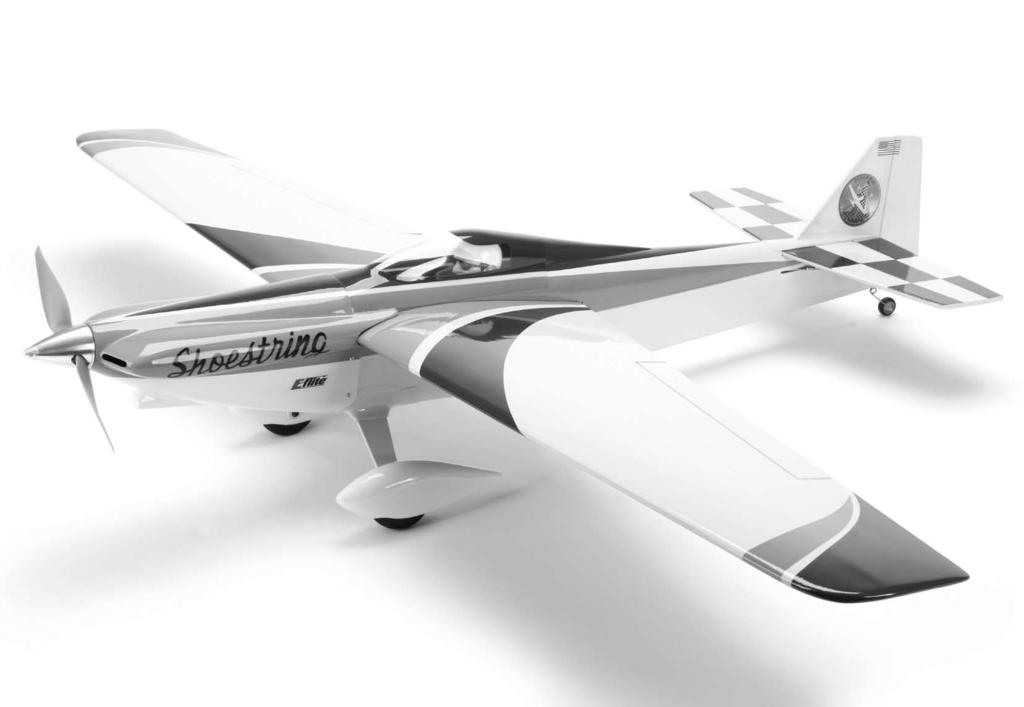
3 Table of Contents Notice... 2 Meaning of Special Language... 2 Warnings... 2 Introduction... 3 Important Information Regarding Warranty Information.3 Specifications... 3 Using the Manual... 3 Contents of Kit/Parts Layout... 4 Covering Colors... 4 Before Starting Assembly... 4 Hardware/Accessory Sizes... 4 Recommended Radio Equipment... 4 Recommended Sport Setup... 4 Recommended Racing Setup... 4 Optional Accessories... 4 Required Tools and Adhesives... 4 Landing Gear Installation... 5 Hinging the Ailerons... 7 Installing the Aileron Servos... 8 Hinging the Elevators Wing and Stabilizer Installation Rudder and Fin Installation Servo and Receiver Installation Motor and Speed Control Installation Cowling Installation Decal Installation Center of Gravity Control Throws Preflight Range Test Your Radio Flying Your Model Daily Flight Checks Limited Warranty Warranty Services Compliance Information for the European Union Academy of Model Aeronautics National Model Aircraft Safety Code Introduction Congratulations on buying the Shoestring 15e. You have purchased what is arguably one of the most fun airplanes in the marketplace today. Originally designed as a fast sport flyer to bring an adrenaline rush to mid- to advanced-level pilots, the project quickly advanced to an even greater purpose. Working with legendary designers Dan Kane and Jerry Small, we developed the airplane into the standard for the upcoming Electric Formula One racing class from the NMPRA (National Miniature Pylon Racing Association). We have designed a unique cowl system that includes all the graceful curves of the front of the fuselage into one piece that stretches back to the mid canopy point. This allows for very easy maintenance, easy mounting of equipment, and great cooling for the EP power system. We also elected to use mini servos throughout to save weight and expense. Power for your airplane can be anything from our Power 15 motor on a 3S setup and 10 x 10E prop (prop clearance limits anything longer) to a full blown race setup with our new Power Kv on 4S and an 8 x 8E prop turning about 15,000 rpm. The sport setup will put you in the 80 mph range while the race setup has been clocked at about 115 mph. The airplane is a smooth flyer and goes exactly where you point it. Make sure all your friends pick up one of these kits, then challenge each other to some impromptu racing for bragging rights at your local field. You ll have a blast! Important Information Regarding Warranty Information Please read our Warranty and Liability Limitations section before building this product. If you as the Purchaser or user are not prepared to accept the liability associated with the use of this Product, you are advised to return this Product immediately in new and unused condition to the place of purchase. Specifications Wingspan: 50.5 in (128cm) Length: 38.3 in (97.3cm) Wing Area: 375 sq in (24.2 sq dm) Weight with battery: lb ( kg) Weight w/o battery: lb ( kg) Using the Manual This manual is divided into sections to help make assembly easier to understand and to provide breaks between each major section. In addition, check boxes have been placed next to each step to keep track of its completion. Steps with a single circle () are performed once, while steps with two or more circles () indicate the step will require repeating, such as for a right or left wing panel, two servos, etc. Remember to take your time and follow the directions. E-flite Shoestring 15e ARF Assembly Manual 3
 EFL420506 EP Standoff set (8pcs) EFL420507 Cowl (painted) EFL420508 Wing tube EFL420509 Fuselage hatch EFL420510 Hardware Bag EFL420511 Landing Gear with Axles EFL420512 Wing Mounting Clips")
4 Contents of Kit/Parts Layout Replacement Parts EFL Fuselage with Hatch EFL Main Wing Set with Ailerons EFL Tail Set EFL Landing Gear with Axle EFL Wheel pants set (painted) EFL EP Standoff set (8pcs) EFL Cowl (painted) EFL Wing tube EFL Fuselage hatch EFL Hardware Bag EFL Landing Gear with Axles EFL Wing Mounting Clips Covering Colors Midnight Blue HANU885 Sky Blue HANU875 Bright Yellow HANU872 Hardware/Accessory Sizes Main wheel 2-inch (52mm) Tail wheel 1/2-inch (13mm) Before Starting Assembly Before beginning the assembly of your model, remove each part from its bag for inspection. Closely inspect the fuselage, wing panels, rudder and stabilizer for damage. If you find any damaged or missing parts, contact the place of purchase. If you find any wrinkles in the covering, use a heat gun (HAN100) and covering glove (HAN150) or covering iron (HAN101) with a sealing iron sock (HAN141) to remove them. Use caution while working around seams or areas where the colors overlap to prevent pulling the seams. Recommended Radio Equipment You will need a minimum 4-channel transmitter, receiver and four servos. Recommended Transmitter SPMR5510 DX5e DSMX 5-Channel Transmitter Only Additional Items SPMAR7010 AR Channel DSMX Receiver SPMSA5030 Mini Digital Aircraft Servo (2) JRPS388 Digital Micro Metal Gear Servo (2) SPMA inch (152mm) Servo Extension (2) Motor: Recommended Sport Setup Speed Control: Battery: Spinner: Propeller: Power 15 Brushless 975Kv Outrunner (EFLM4015A) 40A Pro Switch-Mode BEC BL ESC (EFLA1040) 3200mAh 3S 11.1V 30C Li-Po Battery (EFLB32003S30) 1.5-inch Aluminum Bullet Spinner (EFLSP150B) 10 x 10E (APC10010E) Motor: Recommended Racing Setup Speed Control: Battery: Spinner: Propeller: EFLA110 EFLC3025 Power 25 BL 1250Kv Outrunner (EFLM4025B) 60A Pro Switch-Mode BEC BL ESC (EFLA1060) 4S 14.4V 30C Li-Po Battery (EFLB25004S30) 1.5-inch Aluminum Bullet Spinner (EFLSP150B) 8 x 8E (APC08080E) Optional Accessories Power Meter Celectra 80W AC/DC Multi- Chemistry Battery Charger Required Tools and Adhesives Tools & Equipment Drill Epoxy brush Felt-tipped pen Flat blade screwdriver Low-tack tape Light machine oil Long nose pliers Mixing cup Mixing sticks Needle nose pliers Paper towels Pencil Pin vise Phillips screwdriver: #1, #2 Rubbing alcohol Ruler Sandpaper T-pins Side cutter Square Straight edge Toothpicks Balancing stand (optional) Open end or box wrench: 10mm, 13mm Hook and loop strap (EFLH1444) Hook and loop tape (DUB348) Hobby knife with #11 blade Hex wrench or ball driver: 2.5mm, 3/32-inch, 3mm Drill bit: 1/32-inch (1mm), 1/16-inch (1.5mm), 5/64-inch (2mm), 1/8-inch (3mm), 5/32-inch (4mm) Adhesives Medium CA PAAPT02 Thin CA PAAPT08 Threadlock PAAPT42 30-minute epoxy PAAPT39 Plastic Tape, Clear, 3/4 x 125-inch MMM190CL 4 E-flite Shoestring 15e ARF Assembly Manual

, take note that these are in relationship to the pilot sitting in the cockpit of the aircraft unless noted otherwise.")

5 During the course of building your model, we suggest you use a soft base for the building surface. Such things as a foam stand, large piece of bedding foam or a thick bath towel will work well and help protect the model from damage during assembly. This is not shown in the instructions to provide the greatest detail in the photos. When referencing directions (up, down, left, right, top and bottom), take note that these are in relationship to the pilot sitting in the cockpit of the aircraft unless noted otherwise. Before starting the assembly of your model, we recommend preparing your radio system for installation. This includes charging the transmitter and receiver batteries, as well as centering the trims and sticks on your transmitter. If using a computer radio, make sure to reset a model memory and name it for this particular model. We also recommend binding the transmitter and receiver at this time, following the instructions provided with your radio system. Landing Gear Installation Required Parts Fuselage Wheelpant (right and left) Landing gear fairing (left and right) Main wheel (2) Axle with hardware (2) Aluminum landing gear Located with Fusealge 4mm washer (2) 4mm lock washer (2) 4mm x 15mm socket head bolt (2) Required Tools and Adhesives Felt-tipped pen Drill Light machine oil Drill bit: 5/32-inch (4mm) Threadlock Flat blade screwdriver Hobby scissors Hobby knife with #11 blade Open-end wrench: 10mm Hex wrench or ball driver: 2.5mm, 3mm Always use threadlock on metal-to-metal fasteners to prevent them from vibrating loose. 1. Secure the landing gear to the bottom of the aircraft using two 4mm x 15mm socket head bolts, two 4mm washers and two 4mm lock washers. The straight side of the gear faces to the front of the aircraft. Use a 3mm hex wrench or ball driver to tighten the bolts. 2. Use hobby scissors and a hobby knife with a #11 blade to trim the landing gear fairings. Leave the size of the fairings slightly over-sized. 3. Fit the landing gear fairings over the gear. Slowly trim the fairings to fit to the fuselage. When installed, they will cover the area where the landing gear attaches to the fuselage. Use clear tape to secure the fairings to the fuselage. We highly recommend re-binding the radio system once all the control throws are set. This will keep the servos from moving to their endpoints until the transmitter and receiver connect. E-flite Shoestring 15e ARF Assembly Manual 5


6 4. Remove the hardware from the axle. Place a drop of light machine oil on the axle to help the wheel roll freely. Always use threadlock on metal-to-metal fasteners to prevent them from vibrating loose. 6. Use a 2.5mm hex wrench or ball driver to secure the wheel using the shorter 4mm x 5mm button head screw and 4mm washer removed from the axle. 8. Use the longer 4mm x 12mm button head screw and 4mm washer to secure the wheel and wheel pant to the landing gear. Use a 2.5mm hex wrench or ball driver to tighten the screw. Use a 10mm open-end wrench to hold the axle while tightening the screw. 5. Slide the axle into the wheel. 9. Repeat Steps 4 through 8 to install the remaining wheel and wheel pant on the landing gear. 7. Slide the wheel into the wheel pant. You may need to flex the pant open slightly to get the wheel to fit. 6 E-flite Shoestring 15e ARF Assembly Manual
 1. Remove the aileron and hinges from the wing panel. Use a pin vise and 1/16-inch (1.")


7 Hinging the Ailerons Required Parts Left wing panel with aileron Right wing panel with aileron Required Tools and Adhesives T-pin Thin CA Pin vise Drill bit: 1/16-inch (1.5mm) 1. Remove the aileron and hinges from the wing panel. Use a pin vise and 1/16-inch (1.5mm) drill bit to drill a hole in the center of each hinge slot. Drill holes in both the aileron and wing. This creates a tunnel for the CA to wick into, making a better bond between the hinge and surrounding wood. 3. Place the hinges in the aileron as shown. 4. Slide the aileron back into position. 5. Remove the T-pins, then press the aileron tightly against the wing. Center the aileron in the opening and check that it can move freely without binding at the root or tip. Wick thin CA into the top and bottom of all three hinges. 6. Once the CA has fully cured. Gently pull on the aileron to make sure the hinges are secure. If any hinges are loose, reapply CA to the hinge. Flex the aileron through its range of motion a number of times to break in the aileron hinges. 2. Place a T-pin in the center of each of the three hinges. This will center the hinges when installed in the aileron. When gluing the hinges, do not use CA accelerator. The CA must be allowed to soak into the hinge to provide the best bond between the hinge and surrounding wood. 7. Repeat Steps 1 through 7 to hinge the remaining aileron. E-flite Shoestring 15e ARF Assembly Manual 7
 Metal clevis (2) 2-inch (52mm) linkage with 2mm nut (2) 2mm x 12mm sheet metal screw (4) Control horn backplate (2) 6-inch")
, 5/64-inch (2mm) 1.")


 drill bit to drill the holes for the servo mounting screws. 4.")
8 Installing the Aileron Servos Required Parts Wing panel (right and left) Transmitter Receiver Control horn (2) Receiver battery Thin wing servos with hardware (2) Metal clevis (2) 2-inch (52mm) linkage with 2mm nut (2) 2mm x 12mm sheet metal screw (4) Control horn backplate (2) 6-inch (152mm) servo extension (2) Required Tools and Adhesives Side cutter Phillips screwdriver: #1 Thin CA String or dental floss Pin vise Drill bit: 1/16-inch (1.5mm), 5/64-inch (2mm) 1. Remove the servo cover from the wing by removing the four 2mm x 12mm sheet metal screws using a #1 Phillips screwdriver. Do not let the string fall into the wing as it is used to pull the servo lead through the wing. 2. Install the rubber grommets and brass eyelets in the servo. Place the servo between the tabs on the servo cover with the output of the servo over the opening in the cover. With the servo spaced slightly off the cover, use a pencil to mark the location for the servo mounting screws. 3. Use a pin vise and 1/16-inch (1.5mm) drill bit to drill the holes for the servo mounting screws. 4. Use a #1 Phillips screwdriver to thread a servo mounting screw into each of the holes to cut threads in the surrounding wood. Remove the screw before moving to the next step. 5. Apply 2 3 drops of thin CA in each of the holes to harden the surrounding wood. This will harden the threads so the screws do not easily strip the surrounding wood. 8 E-flite Shoestring 15e ARF Assembly Manual


 drill bit to enlarge the hole")

 servo")
9 6. Secure the servo using the screws provided with the servo and a #1 Phillips screwdriver. The output shaft of the servo will align with the opening in the cover. Center the aileron servo using the radio system. 8. Fit the servo horn to the servo so it is perpendicular to the servo. Use side cutters to remove the arms that do not protrude through the cover. 10. Tie the string around the extension. Use the string to pull the extension through the wing root. 7. Use a pin vise and 5/64-inch (2mm) drill bit to enlarge the hole in the servo arm 1/2 inch (13mm) from the center of the servo horn. Remove the arms from the servo horn that will not be used using side cutters. 9. Use string or dental floss to secure a 6-inch (152mm) servo extension to the aileron servo lead. 11. Apply 1 2 drops of thin CA in each of the holes to harden the surrounding wood for the aileron cover screws. E-flite Shoestring 15e ARF Assembly Manual 9


 drill bit to drill the two holes completely through the aileron")
10 12. Secure the aileron servo cover using the four 2mm x 12mm sheet metal screws remove in step 1 and a #1 Phillips screwdriver. 14. Attach the control horn to the aileron using two 2mm x 12mm sheet metal screws and a control horn backplate. Use a #1 Phillips screwdriver to tighten the screws. 15. With the aileron servo centered, attach the Z-bend of the 2-inch (52mm) pushrod to the aileron servo horn. Thread a clevis on the pushrod. Adjust the clevis so when it is attached to the control horn the aileron is centered. Tighten the 2mm nut against the clevis using needle nose pliers to prevent the clevis from vibrating loose. 13. Use a pin vise and 5/64-inch (2mm) drill bit to drill the two holes completely through the aileron for the aileron control horn mounting screws. The holes have already been started and are easily found on the bottom of the aileron 16. Repeat steps 1 through 15 to install the remaining aileron servo and linkage. 10 E-flite Shoestring 15e ARF Assembly Manual


11 Hinging the Elevators Required Parts Stabilizer and elevator assembly Required Tools and Adhesives Pin vise Drill bit: 1/16-inch (1.5mm) Sandpaper Toothpicks 30-minute epoxy Low-tack tape Square Felt-tipped pen Thin CA T-pins Mixing cups Mixing sticks Paper towels Rubbing alcohol Ruler or straightedge 2. Use a pin vise and 1/16-inch (1.5mm) drill bit to drill a hole in the center of each hinge slot. Drill holes in both the elevators and stabilizer. This creates a tunnel for the CA to wick into, making a better bond between the hinge and surrounding wood. 4. Mix a small amount of epoxy. Use a toothpick to apply the epoxy to the joiner where it contacts the elevators. The top of the elevator and stabilizer are shown in this section of the manual. 1. Remove the stabilizers from the elevator. Also, remove the elevator joiner connecting the elevators. 3. Use sandpaper to roughen the ends of the joiner wire. This provides a surface for the epoxy to bond to when the joiner is installed. 5. Use a toothpick to apply epoxy into the hole for the joiner wire and the exposed wood where the joiner wire fits in the elevators. Steps 6 through 13 can be performed while the epoxy is curing on the joiner wire. E-flite Shoestring 15e ARF Assembly Manual 11


12 6. Insert the joiner wire into both elevator halves. Use low-tack tape to keep the joiner wire in position while the epoxy cures. Use a straight edge to make sure the elevator halves are in alignment with each other. Also make sure the elevator halves lay flat on your work surface. 8. Place a T-pin in the center of each of the six hinges. This will center the hinges when installed in the stabilizer. 11. Make sure the tips of the elevators are aligned with the tips of the stabilizer. 9. Place the hinges in the stabilizer as shown. 12. Press the elevators tightly against the stabilizer. Apply thin CA into the top and bottom of all six hinges. 7. Use a ruler to determine the center of the stabilizer. Use a square and felt-tipped pen to mark the center line on the top of the stabilizer. This will help in aligning the stabilizer on the fuselage later. 10. Slide the elevators in position on the stabilizer. 12 E-flite Shoestring 15e ARF Assembly Manual

")


13 13. Once the CA has fully cured. Gently pull on the elevator to make sure the hinges are secure. If any hinges are loose, reapply CA to the hinge. Flex the elevator through its range of motion a number of times to break in the hinges. Wing and Stabilizer Installation Required Parts Fuselage assembly Wing panels (right and left) Clip (2) Stabilizer assembly Aluminum wing tube Required Tools and Adhesives 30-minute epoxy Phillips screwdriver: #2 Epoxy brush Ruler Felt-tipped pen Mixing cups Mixing sticks Paper towels T-pin Low-tack tape Rubbing alcohol Hobby knife with #11 blade 3. Slide the tube into the socket in the fuselage. Make sure to guide the lead for the aileron servo in the fuselage when positioning the wing. 1. Remove the canopy from the fuselage by sliding it forward, then lifting it from the fuselage at the rear. 4. Use a clip to secure the wing to the fuselage. 2. Slide the aluminum wing tube into the socket in the wing panel. The tube will slide in easily, so do not force it in any farther than it will easily slide. 5. Repeat step 3 to install the second wing panel. E-flite Shoestring 15e ARF Assembly Manual 13
 and view the model from the rear.")


14 A 6. Place the stabilizer in position. Use a T-pin at the rear of the stabilizer and tape at the front so it can be easily repositioned. The line drawn earlier will help in setting the initial alignment. 8. Step back from the model 3 6 feet (1 2 meters) and view the model from the rear. Check that the wing and stabilizer are in alignment with each other. You might need to lightly sand the stabilizer saddle to bring the wing and stabilizer into alignment. When cutting the covering, make sure not to cut into the underlying wood and weaken the stabilizer. Another option is to use a soldering iron or hot knife to melt the covering, rather than cutting, to avoid damaging the stabilizer. Check Alignment 10. Remove the stabilizer from the fuselage. Use a hobby knife with a new #11 blade to trim the covering 1/16 inch (1.5mm) inside the line drawn in the previous step. 7. Measure from each wing tip to corresponding stabilizer tip. These measurements must match exactly for the stabilizer to be in alignment. Remove the tape and move the stabilizer if necessary. 9. After the stabilizer has been aligned, trace the outline of the fuselage on the bottom of the stabilizer using a felt-tipped pen. A 11. Mix 1/2 ounce (15ml) of 30-minute epoxy. Lightly brush epoxy on the stabilizer saddle. A=A 14 E-flite Shoestring 15e ARF Assembly Manual

 T-pins Phillips screwdriver: #1 Hobby knife with #11 blade 2. Use a hobby knife with a new #11 blade to trim the covering 1/16 inch (1.")


15 12. Lightly brush epoxy on the exposed wood on the bottom of the stabilizer. Rudder and Fin Installation Required Parts Fuselage assembly Rudder and fin assembly Required Tools and Adhesives 30-minute epoxy Epoxy brush Square Felt-tipped pen Mixing cup Mixing sticks Paper towels Rubbing alcohol Low-tack tape Thin CA Pin vise Drill bit: 1/16-inch (1.5mm) T-pins Phillips screwdriver: #1 Hobby knife with #11 blade 2. Use a hobby knife with a new #11 blade to trim the covering 1/16 inch (1.5mm) inside the line drawn in the previous step. 13. Secure the stabilizer on the fuselage using tape and a T-pin. Use a paper towel and rubbing alcohol to remove any excess epoxy. Allow the epoxy to fully cure before proceeding. Once cured, remove the T-pin and tape from the stabilizer. 1. Separate the rudder from the fin. Set the hinges aside at this time. Fit the fin into position on the fuselage. Use a felt-tipped pen to trace the outline of the fin on the top of the stabilizer. 3. Mix 1/2 ounce (15ml) of 30-minute epoxy. Lightly brush a thin layer of 30-minute epoxy on the exposed wood of the stabilizer. 14. Once the epoxy has fully cured, remove the wing from the fuselage. When cutting the covering, make sure not to cut into the underlying wood and weaken the stabilizer. Another option is to use a soldering iron or hot knife to melt the covering, rather than cutting, to avoid damaging the stabilizer. E-flite Shoestring 15e ARF Assembly Manual 15

 drill bit to drill a hole in the center of each hinge slot.")


16 4. Brush a thin layer of epoxy on the bottom of the fin as shown. 6. Use a square to make sure the fin is aligned with the stabilizer. 8. Use a pin vise and 1/16-inch (1.5mm) drill bit to drill a hole in the center of each hinge slot. Drill holes in both the rudder and fin at this time. This creates a tunnel for the CA to wick into, making a better bond between the hinge and surrounding wood. 5. Position the fin back on the fuselage. Use a paper towel and rubbing alcohol to remove any excess epoxy. 7. Use low-tack tape to keep the fin in alignment with the stabilizer until the epoxy fully cures. 9. Place a T-pin in the center of each of the three hinges. This will center the hinges when installed in the rudder. 16 E-flite Shoestring 15e ARF Assembly Manual

 2mm x 12mm sheet metal screw (4) Control horn backplate (2) Hook and loop tape (not included) Required Tools and Adhesives Pencil Thin CA")


17 10. Insert the hinges in the rudder. 12. Once the CA has fully cured. Gently pull on the rudder to make sure the hinges are secure. If any hinges are loose, reapply CA and flex the rudder through its range of motion a number of times to break them in. Servo and Receiver Installation Required Parts Fuselage assembly Servo with hardware (2) Receiver Receiver battery Transmitter Control horn (2) 2mm x 12mm sheet metal screw (4) Control horn backplate (2) Hook and loop tape (not included) Required Tools and Adhesives Pencil Thin CA Pin vise Side cutters Needle nose pliers Phillips screwdriver: #1 Drill bit: 1/16-inch (1.5mm), 5/64-inch (2mm) 11. Press the rudder tightly against the fin. Remove the T-pins and apply thin CA to both sides of the three hinges. 1. Prepare the rudder servo by installing the grommets and brass eyelets. Place the rudder servo in the fuselage with the output shaft to the front of the fuselage. Position the servo so the edge toward the center is centered in the opening. Use a pencil to transfer the positions for the mounting screws on the servo tray. E-flite Shoestring 15e ARF Assembly Manual 17
 drill bit to drill the four holes for the servo mounting screws. 4.")


18 2. Remove the servo from the fuselage. Use a pin vise and 1/16-inch (1.5mm) drill bit to drill the four holes for the servo mounting screws. 4. Place 2 3 drops of thin CA in each hole to harden the surrounding wood. This harder surface makes the screws more secure when installed. 6. Use a pin vise and 5/64-inch (2mm) drill bit to enlarge the hole in the servo arm 3/8 inch (10mm) from the center of the servo horn. Remove the arms from the servo horn that will not be used using side cutters. 3. Use a #1 Phillips screwdriver to thread a servo mounting screw into each of the holes to cut threads in the surrounding wood. Remove the screw before moving to the next step. Prepare all four mounting holes at this time. 5. Return the servo to the fuselage. Use a #1 Phillips screwdriver and the screws provided with the servo to secure it in the fuselage. 7. Insert the Z-bend from the pushrod wire through the hole in the servo horn. Use the radio system to center the rudder servo. Install the servo horn so it is perpendicular to the servo center line. Secure the horn using the screw from the servo and a #1 Phillips screwdriver. 18 E-flite Shoestring 15e ARF Assembly Manual


19 8. Use a pin vise and 5/64-inch (2mm) drill bit to drill the two locations for the control horn mounting screws. The locations have been predrilled at the factory. 10. Use a square or straight edge to make sure the rudder is in alignment with the fin. The clevis attaches to the outer hole on the control horn. Adjust the clevis as necessary so the rudder is aligned with the fin when the rudder servo is centered. Once aligned, use needle nose pliers to tighten the nut against the clevis to keep it from vibrating loose. 12. Use hook and loop tape to install the receiver in the fuselage. Connect the rudder and elevator servo to the receiver. Secure the remote receiver in the fuselage using hook and loop tape. 9. Secure the control horn to the rudder using two 2mm x 12mm sheet metal screws and a control horn backplate. Tighten the screws using a #1 Phillips screwdriver. 11. Repeat steps 3 through 10 to connect the elevator pushrod wire. The positions and measurements for the elevator connections are the same as the rudder. When flying in extreme High-G racing, it may be a good idea to use a tie-wrap (not included) to secure the position of the receiver. E-flite Shoestring 15e ARF Assembly Manual 19
 Power 15 motor with accessories Electronic speed control (ESC) 40-Amp Aluminum spacer, 9/16-inch (14mm)")
 (4) 3mm x 20mm button head machine screw (4) Required Tools and Adhesives Threadlock Hook")


20 Motor and Speed Control Installation Required Parts Fuselage assembly Motor battery Tie-wrap (not included) (2) 3mm lock washer (4) Required Parts (Power 15) Power 15 motor with accessories Electronic speed control (ESC) 40-Amp Aluminum spacer, 9/16-inch (14mm) (4) 3mm x 25mm socket head cap screw (4) Required Parts (Power 25) Power 25 motor with accessories Electronic speed control (ESC) 60-Amp Aluminum spacer, 5/16-inch (7mm) (4) 3mm x 20mm button head machine screw (4) Required Tools and Adhesives Threadlock Hook and loop tape Hook and loop strap Phillips screwdriver: #2 Hex wrench or ball driver: 2mm (Power 25) or 2.5mm (Power 15) 2a. Attach the Power 15 motor to the firewall using four 14mm spacers, 3mm x 25mm socket head screws and four 3mm lock washers. Tighten the screws using a 2.5mm hex wrench or ball driver. 2b. Attach the Power 25 motor to the firewall using four 7mm spacers, 3mm x 20mm button head screws and four 3mm lock washers. Tighten the screws using a 2mm hex wrench or ball driver. 3. Route the leads for the motor through the hole in the firewall. Always use threadlock on metal-to-metal fasteners to prevent them from vibrating loose. 1. Use a #2 Phillips screwdriver to attach the X-mount to the motor using the screws provided with the motor. 20 E-flite Shoestring 15e ARF Assembly Manual


 to secure the leads so they don t interfere with the operation of the motor or installation of the")

21 4. Loop a tie-wrap (not included) through the plate in the fuselage right above the landing gear plate. Make sure the tie-wrap is not looped through the battery mounting plate. Matching the colors between the ESC and motor when they are connected results in the correct motor direction if using all E-flite components. 7. Route the battery lead through the opening in the fuselage. The lead for the receiver is routed under the battery tray and receiver, then plugged into the throttle channel of the receiver. Mount the switch from the speed control in the fuselage where it can be accessed when the canopy is removed. 6. Connect the wires from the motor to the wires of the speed control. Use a tie-wrap (not included) to secure the leads so they don t interfere with the operation of the motor or installation of the cowling. 5. Slide the speed control into the fuselage with the battery wires, receiver lead and switch going in and through the tie-wrap. Position the speed control, then tighten the tie-wrap to secure the speed control in the fuselage. The heat sink will face the top of the fuselage. 9. Secure the battery in the fuselage using a hook and loop strap. Also, place hook and loop tape on the battery and fuselage where they contact each other to prevent the battery from moving. E-flite Shoestring 15e ARF Assembly Manual 21
 Required Tools and Adhesives Low-tack tape Thin CA Pin vise Phillips screwdriver: #1 Hex wrench or ball driver: 3/32-inch Open end or box")

 gap between the backplate and cowl. Use two pieces of low-tack tape to hold the cowl in position on the fuselage. 1.")


22 Cowling Installation Required Parts Fuselage assembly Cowling Canopy Propeller 2mm x 6mm sheet metal screw (4) Spinner backplate with adapter (not included) Required Tools and Adhesives Low-tack tape Thin CA Pin vise Phillips screwdriver: #1 Hex wrench or ball driver: 3/32-inch Open end or box wrench: 13mm Drill bit: 1/32-inch (1mm), 5/64-inch (2mm) 2. Place the canopy back on the fuselage and attach the wings. Slide the cowl on the fuselage. You will need to flex the cowl to fit it over the landing gear fairings on the bottom of the fuselage. 4. Slide the propeller adapter and spinner backplate on the motor shaft. Check that the cowl is aligned with the spinner backplate. There should also be a 5/64 inch (2mm) gap between the backplate and cowl. Use two pieces of low-tack tape to hold the cowl in position on the fuselage. 1. Use a pin vise and 5/64-inch (2mm) drill bit to drill the four holes in the cowl for the mounting screws. Indentations in the cowl show where these holes should be drilled. Always balance your propeller. An unbalanced propeller can cause vibrations to be transmitted into the airframe, which could damage the airframe or other components as well as produce unwanted flight characteristics. 6. Once aligned, use a pin vise and 1/32-inch (1mm) drill bit to drill through the holes in the cowl and into the fuselage. 3. Prepare the spinner assembly by sliding the propeller on the adapter shaft. Place the adapter nut on the shaft, but do not tighten it at this time. 22 E-flite Shoestring 15e ARF Assembly Manual


23 7. Remove the cowl from the fuselage. Use a #1 Phillips screwdriver to thread a 2mm x 6mm sheet metal screw into the cowl mounting holes to cut threads in the surrounding wood. Remove the screw before moving to the next step. Prepare all four mounting holes at this time. 9. The cowl can now be secured to the fuselage using the four 2mm x 6mm sheet metal screws. Tighten the screws using a #1 Phillips screwdriver. 11. Position the spinner cone. Make sure the opening in the spinner cone does not contact the propeller. Use a 3/32-inch hex wrench or ball driver to tighten the screw that secures the spinner cone. 8. Remove the cowl from the fuselage. Place 1 2 drops of thin CA in each hole to harden the surrounding wood. This harder surface makes the screws more secure when installed. 10. Install the propeller adapter and backplate on the motor shaft. Use a 13mm box wrench or open end wrench to tighten the propeller nut. E-flite Shoestring 15e ARF Assembly Manual 23


24 Required Parts Fuselage assembly Decal Installation Wing assembly Required Tools and Adhesives Spray bottle Dish washing detergent Paper towel Hobby knife with #11 blade Required Parts Assembled airframe Center of Gravity Required Tools and Adhesives Felt-tipped pen Ruler Balancing stand (optional) 1. Apply the decals to your model using the photos located in this section of the manual and the box art from your model. Use a spray bottle and a drop of dish washing liquid sprayed in the location of the decal to allow repositioning. Use a paper towel as a squeegee to remove excess water from under the decal. Allow the model to rest overnight so the remaining water can evaporate. An important part of preparing the aircraft for flight is properly balancing the model. CAUTION: Do not inadvertently skip this step or property damage and injury could occur. 1. Assemble your model in preparation for flight, making sure the wing is on securely and the motor battery is installed as instructed in this manual. 2. The recommended Center of Gravity (CG) location for your model is 2 3 / 8 to 2 5 / 8 inches (60 to 66mm) back from the leading edge of the wing as shown with the battery pack installed. Mark the location of the CG on the bottom of the wing with a felt-tipped pen. 24 E-flite Shoestring 15e ARF Assembly Manual
25 3. When balancing your model, support the plane upright at the marks made on the bottom of the wing with your fingers or a commercially available balancing stand. This is the correct balance point for your model. Make sure your model is assembled and ready for flight before balancing. Control Throws 1. Turn on the transmitter and receiver of your model. Check the movement of the rudder using the transmitter. When the stick is moved right, the rudder should also move right. Reverse the direction of the servo at the transmitter if necessary. Rudder High Rate Right: 11/16-inch 17mm Left: 11/16-inch 17mm Low Rate Right: 19/32-inch 15mm Left: 19/32-inch 15mm 2. Check the movement of the elevator with the radio system. Moving the elevator stick toward the bottom of the transmitter should make the airplane elevator move up. Measurements are taken at the inner or widest point on the control surface. 3. Check the movement of the ailerons with the radio system. Moving the aileron stick right should make the right aileron move up and the left aileron move down. These are general guidelines measured from our own flight tests. You can experiment with higher rates to match your preferred style of flying. Adjust the motor battery as necessary so the model is level or slightly nose down. This is the correct balance point for your model. You should find the CG to be very close with the battery installed as shown in this manual. Mark the location of the battery on the battery tray using a felt-tipped pen so it can be returned to this position if it is removed from your model. After the first flights, the CG position can be adjusted for your personal preference. 4. Use a ruler to adjust the throw of the elevator, ailerons and rudder. Adjust the position of the pushrod at the control horn to achieve the following measurements when moving the sticks to their endpoints: Aileron High Rate Up: 3/8-inch 10mm Down: 1/4-inch 6mm Low Rate Up: 5/16-inch 8mm Down: 3/16-inch 5mm Elevator High Rate Up: 9/32-inch 7mm Down: 1/4-inch 6mm Low Rate Up: 3/16-inch 5mm Down: 5/32-inch 4mm Travel Adjust and Sub-Trims are not listed and should be adjusted according to each individual model and preference. We highly recommend re-binding the radio system once all the control throws are set. This will keep the servos from moving to their endpoints until the transmitter and receiver connect. E-flite Shoestring 15e ARF Assembly Manual 25
26 Check Your Radio Preflight Before going to the field, make sure your batteries are fully charged per the instructions included with your radio. Charge the transmitter and motor battery for your airplane. Use the recommended charger supplied with your particular radio system, following the instructions provided with the radio. In most cases, the radio should be charged the night before going out flying. Before each flying session, range check your radio. See your radio manual for the recommended range and instructions for your radio system. Each radio manufacturer specifies different procedures for their radio systems. Next, run the motor. With the model securely anchored, check the range again. The range test should not be significantly affected. If it is, do not attempt to fly! Have your radio equipment checked out by the manufacturer. Double-check that all controls (aileron, elevator, rudder and throttle) move in the correct direction. Check the radio installation and make sure all the control surfaces are moving correctly (i.e., the correct direction and with the recommended throws). Check all the control horns, servo horns, and clevises to make sure they are secure and in good condition. Range Test Your Radio Before each flying session, and especially with a new model, it is important to perform a range check. It is helpful to have another person available to assist during the range check. If you are using a Spektrum transmitter, please refer to your transmitter s manual for detailed instructions on the range check process. 1. With the model resting on the ground, stand 30 paces (approximately 90 feet) away from the model. 2. Face the model with the transmitter in your normal flying position. Ensure the throttle is in the full down position and plug the flight battery into the speed control. 3. As you move the controls, watch to be sure the airplane s motor and controls operate smoothly. You should have total control of the model at 30 paces (90 feet). 4. If control issues exist, call the appropriate Horizon Product Support office (see addresses listed in the Warranty Services section of this manual) or go to horizonhobby.com to find a local Spektrum distributor in your country for service when using a Spektrum radio system. Power 15 Sport Setup Flying Your Model If you followed the suggestions for the sport setup, you ll have adequate control throws to do just about any aerobatic maneuver you want from an airplane that is designed to fly fast. Balance the airplane at the 2 3 / 8 inches (60mm) mark to start with and then adjust fore and aft from there by moving the motor battery. The initial CG will provide a very solid feeling airplane that will readily stall with full up elevator, which gives good control for landings. Take-off Use care with a 10-inch propeller mounted, especially off the grass. A smooth application of throttle will result in a fairly straight takeoff run, needing a small amount of right rudder. When the tailwheel is on the ground (before the tail has risen) it provides good authority against any torque-induced yaw... Once the tailwheel lifts off the ground, be prepared to apply additional right rudder to keep the airplane on a straight path. It takes about 8 10 seconds for the airplane to gain full speed, but you don t have to wait for this speed to have fun. With the light wing loading, you ll find the Shoestring 15e to be very maneuverable and fun to fly. Power Kv Racing Setup This setup is an entirely different animal. This setup will raise the top speed from around 80 mph to 115 mph and will provide you with many hours of pure adrenaline (at 4 minutes or so per flight). The size of the loops you can do will amaze you. Balance the airplane at the 2 3 / 8 inches (60mm) mark to start with and then adjust fore and aft from there by moving the motor battery. The initial CG will provide a very solid feeling airplane that will readily stall with full up (high-rate) elevator, which gives good control for landings. We recommend following the suggestions on the pushrod attachment in the manual for the racing setup. Using the inner holes at the servo will result in the greatest amount of torque being delivered to the control surface. At these speeds, it is good to have a reserve of holding power and extra torque. 26 E-flite Shoestring 15e ARF Assembly Manual
27 Take-off With the high Kv motor and a small 8-inch propeller, there is a ton of torque coming from your motor, so be prepared on your first takeoff. The airplane will easily come off the ground at 1/2 throttle, so if you stop yourself from going full bore and wait to apply full power until well airborne, your takeoffs will be easier and a thing of beauty. While the tailwheel is on the ground it provides good authority against any torque-induced yaw, but once the tailwheel lifts off, be prepared to apply additional right rudder to keep the airplane on a straight path. With an 8-inch pitch prop, it takes a full 15 seconds for the airplane to gain full speed. Racing tips The key to going fast and maintaining your speed is to induce the least amount of drag while you are flying the airplane. Every time you move a flight control you increase the drag, so use very little control surface movement to help with this. Get used to using a lot of stick movement on your transmitter (on all axes) and your ability to make smooth corrections and fly a faster line through the air will increase tremendously. I like to set up my transmitter so almost full elevator stick movement is required to complete a turn around a pylon. Ailerons are set up so a complete full roll takes 2 3 seconds (the distance from one end of a racing course to the other). I usually also set up my rudder so that full right rudder will provide a straight takeoff run with a wide open throttle. I also mix in a little rudder with aileron movement (about 4%); just enough so you can roll from right knife edge to left knife edge and back again without gaining any altitude. Some tips on passing your racing friends. Stay above their racing line. There is a tremendous amount of what we call bad air (turbulence) right behind and below them. While it might seem cool and exciting to execute a pass below, at these speeds there is rarely any time to correct from turbulence before your beloved racer is in the ground. Take heed! Landing Landing your model is identical whether you are using the Sport (Power 15) or Racing (Power 25) setups. With the wing loading at about 21 ounces per square foot, the landing speeds for this airplane are actually very slow if you can get it to slow down. It is a very clean airplane and if you let the nose drop on approach, it will pick up all the speed you just worked so hard to lose. Just go to high rate to make sure you have adequate elevator once you get the airplane slowed down when it is least effective. Plan your approach and be prepared to make a go-around on the first few tries. You ll get the hang of it very quickly. Happy Landings! Daily Flight Checks 1. Check the battery voltage of the transmitter battery. Do not fly below the manufacturer s recommended voltage. To do so may cause your aircraft to crash. When you check these batteries, ensure you have the polarities correct on your expanded scale voltmeter. 2. Check all hardware (linkages, screws, nuts, and bolts) prior to each day s flight. Ensure the control surfaces and linkages are not binding and all parts are properly secured. 3. Ensure all surfaces are moving in the proper manner. 4. Perform a ground range check before each day s flying session. 5. Prior to starting your aircraft, turn off your transmitter, then turn it back on. Do this each time you start your aircraft. If any critical switches are on without your knowledge, the transmitter alarm will sound a warning. 6. Check that all trim levers are in the proper location. 7. All servo pigtails and switch harness plugs should be secured in the receiver. Make sure the switch harness moves freely in both directions. E-flite Shoestring 15e ARF Assembly Manual 27
28 Limited Warranty What this Warranty Covers Horizon Hobby, Inc. ( Horizon ) warrants to the original purchaser that the product purchased (the Product ) will be free from defects in materials and workmanship at the date of purchase. What is Not Covered This warranty is not transferable and does not cover (i) cosmetic damage, (ii) damage due to acts of God, accident, misuse, abuse, negligence, commercial use, or due to improper use, installation, operation or maintenance, (iii) modification of or to any part of the Product, (iv) attempted service by anyone other than a Horizon Hobby authorized service center, or (v) Products not purchased from an authorized Horizon dealer. OTHER THAN THE EXPRESS WARRANTY ABOVE, HORIZON MAKES NO OTHER WARRANTY OR REPRESENTATION, AND HEREBY DISCLAIMS ANY AND ALL IMPLIED WARRANTIES, INCLUDING, WITHOUT LIMITATION, THE IMPLIED WARRANTIES OF NON-INFRINGEMENT, MERCHANTABILITY AND FITNESS FOR A PARTICULAR PURPOSE. THE PURCHASER ACKNOWLEDGES THAT THEY ALONE HAVE DETERMINED THAT THE PRODUCT WILL SUITABLY MEET THE REQUIREMENTS OF THE PURCHASER S INTENDED USE. Purchaser s Remedy Horizon s sole obligation and purchaser s sole and exclusive remedy shall be that Horizon will, at its option, either (i) service, or (ii) replace, any Product determined by Horizon to be defective. Horizon reserves the right to inspect any and all Product(s) involved in a warranty claim. Service or replacement decisions are at the sole discretion of Horizon. Proof of purchase is required for all warranty claims. SERVICE OR REPLACEMENT AS PROVIDED UNDER THIS WARRANTY IS THE PURCHASER S SOLE AND EXCLUSIVE REMEDY. Limitation of Liability HORIZON SHALL NOT BE LIABLE FOR SPECIAL, INDIRECT, INCIDENTAL OR CONSEQUENTIAL DAMAGES, LOSS OF PROFITS OR PRODUCTION OR COMMERCIAL LOSS IN ANY WAY, REGARDLESS OF WHETHER SUCH CLAIM IS BASED IN CONTRACT, WARRANTY, TORT, NEGLIGENCE, STRICT LIABILITY OR ANY OTHER THEORY OF LIABILITY, EVEN IF HORIZON HAS BEEN ADVISED OF THE POSSIBILITY OF SUCH DAMAGES. Further, in no event shall the liability of Horizon exceed the individual price of the Product on which liability is asserted. As Horizon has no control over use, setup, final assembly, modification or misuse, no liability shall be assumed nor accepted for any resulting damage or injury. By the act of use, setup or assembly, the user accepts all resulting liability. If you as the purchaser or user are not prepared to accept the liability associated with the use of the Product, purchaser is advised to return the Product immediately in new and unused condition to the place of purchase. Law These terms are governed by Illinois law (without regard to conflict of law principals). This warranty gives you specific legal rights, and you may also have other rights which vary from state to state. Horizon reserves the right to change or modify this warranty at any time without notice. Warranty Services Questions, Assistance, and Services Your local hobby store and/or place of purchase cannot provide warranty support or service. Once assembly, setup or use of the Product has been started, you must contact Horizon directly. This will enable Horizon to better answer your questions and service you in the event that you may need any assistance. For questions or assistance, please direct your to productsupport@horizonhobby.com, or call toll free to speak to a Product Support representative. You may also find information on our website at Inspection or Services If this Product needs to be inspected or serviced, please use the Horizon Online Service Request submission process found on our website or call Horizon to obtain a Return Merchandise Authorization (RMA) number. Pack the Product securely using a shipping carton. Please note that original boxes may be included, but are not designed to withstand the rigors of shipping without additional protection. Ship via a carrier that provides tracking and insurance for lost or damaged parcels, as Horizon is not responsible for merchandise until it arrives and is accepted at our facility. An Online Service Request is available at com under the Support tab. If you do not have internet access, please contact Horizon Product Support to obtain a RMA number along with instructions for submitting your product for service. When calling Horizon, you will be asked to provide your complete name, street address, address and phone number where you can be reached during business hours. When sending product into Horizon, please include your RMA number, a list of the included items, and a brief summary of the problem. A copy of your original sales receipt must be included for warranty consideration. Be sure your name, address, and RMA number are clearly written on the outside of the shipping carton. Notice: Do not ship LiPo batteries to Horizon. If you have any issue with a LiPo battery, please contact the appropriate Horizon Product Support office. 28 E-flite Shoestring 15e ARF Assembly Manual
51in Aerobatic Series Sukhoi SU-26M Almost-Ready-to-Fly. Instruction Manual. Specifications
 51in Aerobatic Series Sukhoi SU-26M Almost-Ready-to-Fly Instruction Manual Specifications Wingspan: 51.2 in (1300mm) Length: 51.2 in (1300mm) Wing Area: 581 sq in (37.5sq dm) Flying Weight: 3.5 lb (1600g)
I n s t r u c t i o n M a n u a l. Instruction Manual SPECIFICATION
 I n s t r u c t i o n M a n u a l Instruction Manual SPECIFICATION - Wingspan: 3200mm (125,9 in) - Length: 1650mm (64,9 in) - Flying weight: 3000gr 3200gr - Wing area: 64.5 dm2 - Wing loading: 46g/dm2
AVIATOR 25 ARF Almost Ready-to-Fly
 AVIATOR 25 ARF Almost Ready-to-Fly Instruction Manual Specifications Wingspan: 54.3 in (1380mm) Length: 45.2 in (1150mm) Wing Area: 438 sq in (34sq dm) Flying Weight: 3.8 b (1700g) Dear Customer, Congratulations
RECOMMENDED MOTOR AND BATTERY SET UP
 SPECIFICATION - Wingspan: 6000mm (236.2 in) - Length: 2873mm (113.1 in) - Flying weight: 14-18 kg - Wing area: 219.4 dm2 - Wing loading: 64g/dm2 - Wing type: HQ airfoils - Covering type: Genuine ORACOVER
Aviator Pro 120 ARF. Instruction Manual. Specifications
 Aviator Pro 120 ARF Instruction Manual Specifications Wingspan: 110 in (2800 mm) Length: 74 in (1870 mm) Wing Area: 1581sq in (102 sq dm) Weight: 11.4-13.4 lbs (5190-6100 g) Dear Customer, Congratulations
Assembly Manual. Mini Funtana
 Assembly Manual Mini Funtana Table of Contents Introduction... 2 Specifications... 3 Additional Required Equipment... 3 Additional Tools and Adhesives... 3 Optional Parts... 4 Important Information About
96in Super Decathlon ARF
 96in Super Decathlon ARF Instruction Manual Specifications Wingspan: 96in (2438mm) Length: 63.5 in (1614mm) Weight: Approx. 13lbs (6.5kg) 1 Dear Customer, Congratulations on your purchase of Super Decathlon
MS:159 ASSEMBLY MANUAL. Graphics and specifications may change without notice.
 ASSEMBLY MANUAL MS:159 Graphics and specifications may change without notice. Specifications: Wing span ----------------------------61.8in (157cm). Wing area -----------------1100.5sq.in (71.0sq dm). Weight
I/C FLIGHT GUIDELINES
 SPECIFICATION - Wingspan: 3500mm (137.8 in) - Length: 1650mm (64.96 in) - Flying weight: 3700-4000 gr - Wing area: 75 dm2 - Wing loading: 49g/dm2 - Wing type: HQ profile - Covering type: Genuine ORACOVER
48in Sbach-342. Instruction Manual. Specifications
 48in Sbach-342 Instruction Manual Specifications Wingspan: 48in (1219mm) Length: 46in (1163mm) Wing Area: 471sq in (30.4sq dm) Flying Weight: 1.8-2.0lb (800-900g) Dear Customer, www.valuehobby.com/48in-s342-arf.html
8mm EPP Acrocub. Instruction Manual. Specifications
 8mm EPP Acrocub Instruction Manual Specifications Wingspan: 34.6 in (880mm) Length: 31.5 in (800mm) Wing Area: 213.9 sq in (13.8sq dm) Flying Weight: Approx. 9oz (270g) Dear Customer, www.valuehobby.com/8mm-epp-acrocub.html
Instruction Manual. Item No: AL506
 Instruction Manual Item No: AL506 Specifications: Wingspan: 2218mm (87.3 in) Length: 1892mm (74.5 in) Wing Area: 100dm2 (1550 sq in) Flying Weight: 7.3kg (16.1 lbs) Engine(not incl.): 50-60cc Gas Radio(not
Neptune Seaplane25 ARF. Instruction Manual. Specifications
 Neptune Seaplane25 ARF Instruction Manual Specifications Wingspan: 1270mm (50in) Length: 1155mm (45.5in) Wing Area: 34.8 sq dm (539.4 sq in) Weight: 1950g (4.30lbs) Product Highlights Removable hatch on
WE GET PEOPLE FLYING T-34
 TM WE GET PEOPLE FLYING T-34 Mentor ASSEMBLY MANUAL Specifications Wingspan:... 57.25 in (1454 mm) Length:... 45 in (1146 mm) Wing Area:... 555 sq in (35.8 sq dm) Weight:... 6 7 lb (2.7 kg 3.2 kg) Radio:...
RADIO CONTROL MODEL HURRICANE
 RADIO CONTROL MODEL VQAA040G VQAA040B HURRINE Almost ready to fly SPECIFITIONS Wingspan...63 in. / 161cm Length...50 in. / 129cm Engine...50~60 2T / 70~90 4T Or Electric equivalent. RC Functions: Motor
RECOMMENDED MOTOR AND BATTERY SET UP
 SPECIFICATION - Wingspan: 1404mm (55.3in) - Length: 1134mm (44. 6 in) - Flying weight: 3.2-3.4 kg - Covering type: Genuine ORACOVER - Spinner size: scale type (not included) - Radio: 4 channel minimum
1100MM P-51 Mustang ELECTRIC POWERED REMOTE CONTROL AIRPLANE ELEVENHOBBY.COM
 1100MM P-51 Mustang ELECTRIC POWERED REMOTE CONTROL AIRPLANE ELEVENHOBBY.COM WARNING: Read the ENTIRE instruction manual to become familiar with the features of the product before operating. Failure to
Radio control model INSTRUCTION MANUAL PYLON RACING. Wingspan: 1148mm (45.2 ) Radio : 4 channels Engine : two-stroke
 Radio : 4 channels Engine : two-stroke") VQA038 VQA039 Radio control model INSTRUCTION MANUAL MAGIC PYLON RACING Wingspan: 1148mm (45.2 ) Radio : 4 channels Engine :.25 -.32 two-stroke WARNING! This radio control model is not a toy. If modified
VQA038 VQA039 Radio control model INSTRUCTION MANUAL MAGIC PYLON RACING Wingspan: 1148mm (45.2 ) Radio : 4 channels Engine :.25 -.32 two-stroke WARNING! This radio control model is not a toy. If modified
MS:176 ASSEMBLY MANUAL. Graphics and specifications may change without notice.
 ASSEMBLY MANUAL MS:176 Graphics and specifications may change without notice. Specifications: Wing span ------------------------------98.4in (250cm). Wing area ----------------1576.4sq.in (101.7sq dm).
INSTRUCTION MANUAL WARNING
 INSTRUCTION MANUAL WARNING Please make sure you read the entire instruction manual to become familiar with the features of your aircraft before operating. Failure to operate this product correctly can
ALMOST READY TO FLY. Wing Span in cm. 2
 ASSEMBLY MANUAL ALMOST READY TO FLY MS:X9 Specifications Wing Span --------------------------61.4 in ---------------------------156cm. 2 Wing Area --------------------------606.1 sq.in ------------------
Very Fun & Easy NOTICE
 Very Fun & Easy NOTICE NOTICE All instructions, warranties and other collateral documents are subject to change at the sole discretion of our company. For up-to-date product literature, Visit our website
Instruction Manual. Specification:
 Instruction Manual L O W Specification: Wingspan: 133 cm (52.3 inches) Length : 104 cm (40.9 inches) Weight : 1790gr Engine : 25-32 two stroke Radio : 4 channel - 4 servo W I N G KIT CONTENTS: We have
MS:183 ASSEMBLY MANUAL. Graphics and specifications may change without notice.
 MS:183 ASSEMBLY MANUAL Graphics and specifications may change without notice. Specifications: Wing span ------------------------------79.9in (203cm). Wing area -----------------1165.6sq.in (75.2sq dm).
RECOMMENDED MOTOR AND BATTERY SET UP
 SPECIFICATION - Wingspan: 2190mm (86.2 in) - Length: 1907mm (75 in) - Flying weight: 9000-12000 gr - Wing area: 92 dm2 - Wing loading: 98g/dm2 - Wing type: Naca airfoils - Retract gear type: Air-retract
40 EP Gee Bee Y Scale ARF V2 Instruction Manual Specs:
 40 EP Gee Bee Y Scale ARF V2 Instruction Manual Specs: Wing Span: 40" Overall length: 30" Wing area: 306 sq. in Ready to fly weight: 28~32 oz Motor/Engine: Electric: Uranus-28309 brushless outrunner motor,
Instruction Manual book
 book ITEM CODE:BH 115. SPECIFICATION Wingspan : 6,000 mm 236,22 in. Length : 2,740 mm 107,87 in. Weight : 17.5kg 38.5Lbs. Radio : 08 channels. Servo : 07-08 HS-5685MH(HITEC) Battery : 2 Cells-Li-Po 7.4V
EXTRA 330LX. Specifications: Code: SEA274. Graphics and specifications may change without notice. ASSEMBLY MANUAL
 ASSEMBLY MANUAL EXTRA 330LX Code: SEA274 Graphics and specifications may change without notice. Specifications: Wingspan---------------82.0 in (208.2 cm). Wing area---------------1349.4 sq.in ( 87.1 sq.dm).
Funtana 125 ARF Assembly Manual
 Funtana 125 ARF Assembly Manual Specifications Wingspan... 69.5 in (1765 mm) Length... 68.5 in (1745 mm) Wing Area...1108 sq in (71.5 sq dm) Weight... 8.0 8.5 lb (3.63 4.03 kg) Engine Size....61 1.20 2-stroke;.90
F3P Instruction Manual
 Before use, please read the explanations carefully! F3P Instruction Manual Specifications Fuselage length: 884mm ( 34. Bin ) Wingspan : 845mm ( 33. 2in) Flying Weight : 135-160g (with battery) Additional
SPARC! is distributed exclusively by Horizon Hobby, Inc.
 SPARC! is distributed exclusively by Horizon Hobby, Inc. 05 Fieldstone Road Champaign, IL 68 006 CHOKING HAZARD Small parts. Not for children under years. OWNER S MANUAL Keep these instructions for future
FUN-50 ARF ASSEMBLY MANUAL
 FUN-50 ARF ASSEMBLY MANUAL This Manuel is the sole property of Kangke Industrial USA, Inc. Reproducing any part without the consent of Kangke Industrial USA, Inc. is a lawful violation. Kangke Industrial
Saratoga 40 Assembly Manual
 Saratoga 40 Assembly Manual Specifications Wingspan:... 64.2 in (1630mm) Length:...49.25 in (1251.8mm) Wing Area:...694 sq in (44.77 sq dm) Weight:... 5.5 6.25 lb (2.49 2.83 kg) Radio:...4-channel w/4
the leading edge of the wing, at the fuselage - Length: 1540mm (60.6 in) 10% expo; High: 15mm up/down, 10% expo - Wing area: 40dm2
 10% expo; High: 15mm up/down, 10% expo - Wing area: 40dm2") SPECIFICATION - Gravity CG: 165-170 mm (6.5-6.7 in) Back from - Wingspan: 1400mm (55.1 in) the leading edge of the wing, at the fuselage - Length: 1540mm (60.6 in) - Control throw Ailerons: Low: 12mm up/down,
SPECIFICATION - Gravity CG: 165-170 mm (6.5-6.7 in) Back from - Wingspan: 1400mm (55.1 in) the leading edge of the wing, at the fuselage - Length: 1540mm (60.6 in) - Control throw Ailerons: Low: 12mm up/down,
Instruction Manual book
 Instruction Manual book ITEM CODE:BH118. SPECIFICATION Wingspan : 1,050 mm 41.34 inches. Length : 950mm 37.4 inches. Weight : 1 kg 2.2 lbs. Radio : 04 channels. Servo : 4 mini servos. Motor : KMS 2814/05
Jackal 50 ARF Assembly Manual
 Jackal 50 ARF Assembly Manual Notice Table of Contents Notice...2 The Jackal 50 ARF is a Mike McConville design capable of All instructions, warranties and other collateral Meaning of Special Language...2
RADIO CONTROL MODEL ASSEMBLY INSTRUCTIONS. Wasp
 RADIO CONTROL MODEL ASSEMBLY INSTRUCTIONS Wasp TRAINER Almost ready-to-fly Wingspan 1520mm Fuselage length 1105mm Engine: 40-46 2T / 52-60 4T Electric Motor: 600-700W Radio: 5 channel / 4-5 servo RC Functions:
Ultimate FX 3D. Assembly Manual
 Ultimate FX 3D Assembly Manual Table of Contents Introduction...2 Specifications...2 Contents of Kit/Parts Layout...3 Required Electronics & Accessories...4 High Power Motor Setup*...4 High Power Outrunner
CONFIGURATION(astro/blaze) REQUIRES #
 REQUIRES #") CONFIGURATION(astro/blaze) Length: 29.1in(740mm) Wing Span: 31.9in / 31.1in(810 / 790mm) Wing Area: 1.61 / 1.53ft²(15 / 14.2dm²) Flying Weight: 21oz(600g) REQUIRES Radio control system with 4 channels(delta-mix.)
CONFIGURATION(astro/blaze) Length: 29.1in(740mm) Wing Span: 31.9in / 31.1in(810 / 790mm) Wing Area: 1.61 / 1.53ft²(15 / 14.2dm²) Flying Weight: 21oz(600g) REQUIRES Radio control system with 4 channels(delta-mix.)
RECOMMENDED MOTOR AND BATTERY SET UP
 SPECIFICATION - Wingspan: 1410mm (55.5 in) - Length: 1278mm (50.3 in) - Flying weight: 3.2-3.4 kg - Wing area: 41.3 dm2 - Wing loading: 75g/dm2 - Wing type: Naca airfoils - Covering type: Genuine ORACOVER
Losi (LOSB9810) 2400mAh 11.1V LiPo Transmitter Battery for JR Z1, KoPropo Helios, and Other Radios of Similar Battery Configuration
 2400mAh 11.1V LiPo Transmitter Battery for JR Z1, KoPropo Helios, and Other Radios of Similar Battery Configuration") Losi (LOSB9810) 2400mAh 11.1V LiPo Transmitter Battery for JR Z1, KoPropo Helios, and Other Radios of Similar Battery Configuration Safety Precautions: User Manual 1. Read all safety precautions prior
Losi (LOSB9810) 2400mAh 11.1V LiPo Transmitter Battery for JR Z1, KoPropo Helios, and Other Radios of Similar Battery Configuration Safety Precautions: User Manual 1. Read all safety precautions prior
RECOMMENDED MOTOR AND BATTERY SET UP
 SPECIFICATION - Wingspan: 2000mm (78.7in) - Length: 1544mm (60.7 in) - Flying weight: 3600-3800 gr - Wing area: 66 dm2 - Wing loading: 55g/dm2 - Wing type: Naca airfoils - Covering type: Genuine ORACOVER
Gent EPP. Before use please read the explanations carefully
 Before use please read the explanations carefully Gent EPP Instruction Manual Specifications Fuselage length 900mm 35in Wingspan 820mm 32in Flying Weight 210 240g with battery Additional Required Equipment
F3D-30 ARF ASSEMBLY MANUAL
 F3D-30 ARF ASSEMBLY MANUAL This Manuel is the sole property of Kangke Industrial USA, Inc. Reproducing any part without the consent of Kangke Industrial USA, Inc. is a lawful violation. Kangke Industrial
ALMOST READY TO FLY. Wing Span in cm. 2
 ASSEMBLY MANUAL ALMOST READY TO FLY MS: X12 A - B Graphics and specfications may change without notice. Kit features. Specifications Wing Span ------------------------------- 42.7 in ---------------------
Instruction Manual book
 Instruction Manual book ITEM CODE:BH118. SPECIFICATION Wingspan : 1,050 mm 41.34 inches. Length : 950mm 37.4 inches. Weight : 1 kg 2.2 lbs. Radio : 04 channels. Servo : 4 mini servos. Motor : BL2215/20
P-47D-40 Thunderbolt 30cc ARF Assembly Manual
 P-47D-40 Thunderbolt 30cc ARF Assembly Manual Notice All instructions, warranties and other collateral documents are subject to change at the sole discretion of Horizon Hobby, Inc. For up-to-date product
Turbinator-2 Build Manual
 Turbinator-2 Build Manual Thank you for your purchase of the Turbinator-2 sport jet by Boomerang RC Jets. This RC Jet IS NOT A TOY and should only be flown and operated by experienced RC Turbine Pilots.
AC/DC Powered Peak Detection Fast Charger for 4- to 8-Cell Ni-Cd & Ni-MH Batteries
 AC/DC Powered Peak Detection Fast Charger for 4- to 8-Cell Ni-Cd & Ni-MH Batteries 2010 Horizon Hobby, Inc. 4105 Fieldstone Road Champaign, IL 61822 USA Dynamite products are distributed exclusively by
SBACH SCALE 1:4 ½ ARF
 SPECIFICATION - Wingspan: 1663mm (65.5 in) - Length: 1638mm (64.5 in) - Flying weight: 4700-5200 gr - Wing area: 56 dm2 - Wing loading: 85g/dm2 - Wing type: Naca airfoils - Covering type: Genuine ORACOVER
P-47 Thunderbolt. Assembly Manual
 P-47 Thunderbolt Assembly Manual Table of Contents Table of Contents...2 Specifications...2 Contents of Kit/Parts Layout...3 Required Radio Equipment...4 Required Power System Equipment...4 Required Tools
SIZE.120 OR 30CC SCALE 1:5 ARF
 PC21 PILATUS MK2 SIZE.120 OR 30CC SCALE 1:5 ARF SPECIFICATION - Wingspan: 1772mm (69.72in) - Length: 2019mm (79.5 in) - Flying weight: 6.4-7.2 kg - Wing area: 57.6 dm2 - Wing loading: 113g/dm2 - Wing type:
MARACANA ASSEMBLY INSTRUCTION .40 ARF LOW WING TRAINER RADIO CONTROL MODEL. Every body can fly
 RADIO CONTROL MODEL ASSEMBLY INSTRUCTION MARACANA.40 ARF LOW WING TRAINER Every body can fly VQA085 EP GP You can use both Gas or Electric power Wingspan: 59in.(1520mm) Fuselage length: 48in.(1220mm) Engine:
Instruction Manual book
 book Item code:bh131 SPECIFICATION Wingspan : 3,000 mm 118.1 in. Length : 1,600 mm 62.99 in. Weight : 2.2 kg 4.84 Lbs. Radio : 05 channels. Servo : 06 mini servos. Electric Motor: BOOST 40 Battery : 3celIs
Eratix 3D 25e. Assembly Manual. Specifications
 Eratix 3D 25e Assembly Manual Specifications Wingspan: 54 in (1370 mm) Fuselage Length: 53 in (1350 mm) Wing Area: 695 sq in (44.9 sq dm) Weight of Model w/o Battery: 3 3.25 lb (1.4 1.5 kg) Weight of Model
Instruction Manual. Wingspan : 2270mm (89.37 inches) : 1870mm (73.62 inches) : 7400gr gr. : 4 channel - 6 standard servo.
 : 1870mm (73.62 inches) : 7400gr gr. : 4 channel - 6 standard servo.") Wingspan : 2270mm (89.37 inches) g Length : 1870mm (73.62 inches) Weight : 7400gr - 7600gr Radio : 4 channel - 6 standard servo Engine : 25cc-35cc KIT CONTENTS: We have organized the parts as they come
Wingspan : 2270mm (89.37 inches) g Length : 1870mm (73.62 inches) Weight : 7400gr - 7600gr Radio : 4 channel - 6 standard servo Engine : 25cc-35cc KIT CONTENTS: We have organized the parts as they come
RECOMMENDED EDF AND BATTERY SET UP
 SPECIFICATION - Wingspan: 1150mm (45.3 in) - Length: 1587mm (62.5 in) - Flying weight: 5.0-5.3 kg - Wing area: 40dm2 - Wing loading: 125g/dm2 - Wing type: Naca airfoils - Covering type: Genuine ORACOVER
SK-50 ARF ASSEMBLY MANUAL
 SK-50 ARF ASSEMBLY MANUAL Kangke Industrial USA, Inc. 65 East Jefryn Blvd. Deer Park NY 11729 http://www.kangkeusa.com E-mail: info@kangkeusa.com Tel: 1-877-203-2377 Fax: 1-631-274-3296 Congratulations!
: 6 channel - 9 servo
 g Wingspan : 2005mm (78.94 inches) Length : 1640mm (64.57 inches) Weight : 6400g - 6600g Engine : 25cc - 35cc Radio : 6 channel - 9 servo KIT CONTENTS: We have organized the parts as they come out of
SU-31 PROFILE ELECTRIC ARF ASSEMBLY MANUAL
 SU-31 PROFILE ELECTRIC ARF ASSEMBLY MANUAL 1 TABLE OF CONTENTS Page Aeroworks Contact Information... 3 Introduction.. 4 Kit Contents... 5 Items needed to complete 6 Wing Assembly. 7 Stab Assembly. 10 Flight
Mini Pulse XT. Assembly Manual
 Mini Pulse XT Assembly Manual Table of Contents Introduction...3 Specifications...3 Using the Manual...3 Contents of Kit/Parts Layout...4 Required Radio Equipment...5 Important Information About Motor
ASSEMBLY MANUAL
 www.seagullmodels.com MS: X104 ASSEMBLY MANUAL Graphics and specifications may change without notice. Specifications: Wing span ----------------- 35.4in (90.0cm). Wing area ------------------392.2sq.in
25-Size Float Set. Assembly Manual
 25-Size Float Set Assembly Manual Table of Contents Introduction...2 Tools Required...2 Adhesives Required...3 Using the Manual...3 Replacement Parts...3 Limited Warranty Period...4 Limited Warranty &
YAK-55M 1.8. Forget the rest - a YAK ist the best! Assembly instructions. Gernot
 YAK-55M 1.8 Assembly instructions Forget the rest - a YAK ist the best! Gernot Table of contents 1.Specifications (metric units)...2 2.Recommended Setups...2 3.Required tools and adhesives:...2 4.Warning...3
YAK54 MK2. GP/EP size.120/20cc SCALE 1:4 ¾ ARF. Instruction Manual. version. version
 Instruction Manual GP EP version version GP/EP size.10/0cc SCALE 1:4 ¾ ARF SPECIFICATION - Wingspan: 168 (66.3 in) - Length: 1605mm (63.1 in) - Flying weight: 4700-500 gr - Wing area: 54.7 dm - Wing loading:
Taylorcraft 26cc BNF Assembly Manual
 Taylorcraft 26cc BNF Assembly Manual TM Notice Table of Contents Introduction Intro...2 The Hangar 9 Taylorcraft 26cc BNF is a gorgeous giant-scale All instructions, warranties and other collateral Product
Vision Ultra AC/DC Charger
 Vision Ultra AC/DC Charger Operation Manual www.dynamiterc.com Notice All instructions, warranties, and other collateral documents are subject to change at the sole discretion of Horizon Hobby, Inc. For
Instruction Manual. Wingspan : 1884 mm (74.17 in) Length. Weight. Engine. : 4 channels / 5 servo standard. : 1450 mm (57.
 Length. Weight. Engine. : 4 channels / 5 servo standard. : 1450 mm (57.") Wingspan : 1884 mm (74.17 in) Length : 1450 mm (57.09 in) Weight : 4000 gr Engine : 60 two strokes Radio : 4 channels / 5 servo standard KIT CONTENTS: We have organized the parts as they come out of the
Wingspan : 1884 mm (74.17 in) Length : 1450 mm (57.09 in) Weight : 4000 gr Engine : 60 two strokes Radio : 4 channels / 5 servo standard KIT CONTENTS: We have organized the parts as they come out of the
RECOMMENDED MOTOR AND BATTERY SET UP
 SPECIFICATION - Wingspan: 1800mm (70.8 in) - Length: 1355mm (53.3 in) - Flying weight: 4100-4300 g - Wing area: 51 dm2 - Wing loading: 80g/dm2 - Wing type: Naca airfoils - Covering type: Genuine ORACOVER
HERO 3D SCALE 1:6 ARF
 Instruction Manual SPECIFICATION - Wingspan: 1500mm(59 in) - Length: 1410mm (55.5 in) - Flying weight: 2100-2300 gr - Wing area: 58 dm2 - Wing loading: 39g/dm2 - Covering type: Genuine ORACOVER - Gear
Instruction Manual. Wingspan : 1400 mm (55.12 inch) : 1480 mm (58.27 inch) : 5500gr gr. : 6-9 channel/ 8 servo high torque,1 standard
 : 1480 mm (58.27 inch) : 5500gr gr. : 6-9 channel/ 8 servo high torque,1 standard") Wingspan : 1400 mm (55.12 inch) g Length : 1480 mm (58.27 inch) Weight : 5500gr - 6000gr Radio : 6-9 channel/ 8 servo high torque,1 standard Engine : GT 22 OS KIT CONTENTS: We have organized the parts
Wingspan : 1400 mm (55.12 inch) g Length : 1480 mm (58.27 inch) Weight : 5500gr - 6000gr Radio : 6-9 channel/ 8 servo high torque,1 standard Engine : GT 22 OS KIT CONTENTS: We have organized the parts
: 7 channel - 9 servo, Hi-Torque ( Minimum 6 kg ).
.") g Wingspan : 1820mm (71.65 inches) Length : 1625mm (63.98 inches) Weight : 6900gr Engine : 25cc - 35cc Radio : 7 channel - 9 servo, Hi-Torque ( Minimum 6 kg ). KIT CONTENTS: We have organized the parts
g Wingspan : 1820mm (71.65 inches) Length : 1625mm (63.98 inches) Weight : 6900gr Engine : 25cc - 35cc Radio : 7 channel - 9 servo, Hi-Torque ( Minimum 6 kg ). KIT CONTENTS: We have organized the parts
RECOMMENDED MOTOR AND BATTERY SET UP
 SPECIFICATION - Wingspan: 1420mm (55.91 in) - Length: 1370mm (53.94 in) - Flying weight: 2600-2800 gr - Wing area: 41.6 dm2 - Wing loading: 65g/dm2 - Wing type: Naca airfoils - Covering type: Genuine ORACOVER
MEMO. No.4341 Specification: Wing Span: 29.1 (740mm) Length: 36.6 (930mm) 2. Warranty
 Length: 36.6 (930mm) 2. Warranty") MEMO No.4341 Specification: Wing Span: 29.1 (740mm) Length: 36.6 (930mm) 2 Wing Area: 299 sq.in. (19.29 dm ) Weight: 18.9oz. (536.5g) 2 Wing loading: 0.58 oz./sq.ft (27.8g/dm ) Motor: OBL 29/27-07A Warranty
MEMO No.4341 Specification: Wing Span: 29.1 (740mm) Length: 36.6 (930mm) 2 Wing Area: 299 sq.in. (19.29 dm ) Weight: 18.9oz. (536.5g) 2 Wing loading: 0.58 oz./sq.ft (27.8g/dm ) Motor: OBL 29/27-07A Warranty
Extra ARF. Assembly Manual. Specifications
 Extra 260 480 ARF Assembly Manual Specifications Wingspan: 43 in (1090mm) Length: 40 in (1015mm) Wing Area: 375 sq in (24.2 sq dm) Weight w/o Battery: 23 24 oz (650 680 g) Weight w/battery: 26 29 oz (740
(Glider) ASSEMBLY MANUAL
 ASSEMBLY MANUAL") (Glider) MS:132 ASSEMBLY MANUAL Graphics and specifications may change without notice. Specifications: Wing span ------------------------------118.1in (300cm). Wing area ---------------------902.1sq.in
(Glider) MS:132 ASSEMBLY MANUAL Graphics and specifications may change without notice. Specifications: Wing span ------------------------------118.1in (300cm). Wing area ---------------------902.1sq.in
MS:174 ASSEMBLY MANUAL. Graphics and specifications may change without notice.
 MS:174 ASSEMBLY MANUAL Graphics and specifications may change without notice. Specifications: Wing span ------------------------------79.9in (203cm). Wing area -----------------911.4sq.in (58.8sq dm).
Ultimate ARF
 Ultimate 20-300 10 ARF Assembly Manual Specifications Wingspan: 38 in (960mm) Length: 41 in (1045mm) Wing Area: 473.5 sq in (30.5 sq dm) Weight w/o Battery: 34 36 oz (965 1020 g) Weight w/battery: 39 41
RECOMMENDED MOTOR AND BATTERY SET UP
 SPECIFICATION - Wingspan: 1600mm (63 in) - Length: 1285mm (50.5 in) - Flying weight: 2800-3200 gr - Wing area: 40.1 dm2 - Wing loading: 78g/dm2 - Wing type: Naca airfoils - Covering type: Genuine ORACOVER
64MM F-16 Fighting Falcon V2
 64MM F-16 Fighting Falcon V2 SIMPLE Simple assembly RIGID STRONG DURABLE EPO STABLE SMOOTH FLYING PERFORMANCE FMSMODEL.COM Table of Contents Introductions 3 Contents of Kit 4 Assemble the plane 5 Battery
Instruction Manual book
 Instruction Manual book SPECIFICATION Wingspan : 1,800mm. 70.87 in. Length : 1,350 mm. 53.15in. Weight : 3.6kg. 7.92lbs. Parts Listing required (not included). Glow Engine : 55-61 2 stroke. 91 4 stroke.
Please read all instructions carefully before assembly and flight!
 c c Please read all instructions carefully before assembly and flight! Thank you for purchasing the. This model is designed for the intermediate to advanced flyer. The model is receiver-ready and includes
Instruction Manual book
 book SPECIFICATION Wingspan : 1,450 mm 57.09 in. Length : 1,200mm 47.24in. Weight : 3.1 kg 6.82 Lbs. Radio : 05 channels. Servo : 07 servos. Engine : 61-75 2 stroke. 91 4 stroke. Made in Vietnam. This
RECOMMENDED MOTOR AND BATTERY SET UP
 SPECIFICATION - Wingspan: 2567mm (101in) - Length: 2190mm (86.2 in) - Flying weight: 11-13 kg - Wing area: 101 dm2 - Wing loading: 99g/dm2 - Wing type: Naca airfoils - Covering type: Genuine ORACOVER -
JUNKERS CL1 G-BUYU. Specifications: Code: SEA275. Graphics and specifications may change without notice. ASSEMBLY MANUAL
 ASSEMBLY MANUAL JUNKERS CL1 G-BUYU Code: SEA275 Graphics and specifications may change without notice. Specifications: Wingspan---------------68.9 in (175 cm). Wing area---------------776.6 sq.in ( 50.1
MS:136 ASSEMBLY MANUAL. Graphics and specifications may change without notice.
 ASSEMBLY MANUAL MS:136 Graphics and specifications may change without notice. Specifications: Wing span ----------------------------79.5in (202cm). Wing area -----------------965.7sq.in (62.3sq dm). Weight
Instruction Manual. Wingspan : 1400mm (55.12 in) : 1370mm (53.94 in) : 2600gr gr. : 4 channel / 5 servo. : / 2 stroke_52-71 / 4 stroke
 : 1370mm (53.94 in) : 2600gr gr. : 4 channel / 5 servo. : / 2 stroke_52-71 / 4 stroke") Instruction Manual 540 Wingspan : 1400mm (55.12 in) g Length : 1370mm (53.94 in) Weight : 2600gr - 2800gr Radio : 4 channel / 5 servo Engine : 46-52 / 2 stroke_52-71 / 4 stroke KIT CONTENTS: We have organized
Instruction Manual 540 Wingspan : 1400mm (55.12 in) g Length : 1370mm (53.94 in) Weight : 2600gr - 2800gr Radio : 4 channel / 5 servo Engine : 46-52 / 2 stroke_52-71 / 4 stroke KIT CONTENTS: We have organized
PilotRC Trainer USER MANUAL
 PilotRC Trainer USER MANUAL Introduction Thank you for purchasing our Trainer plane. we strive to achieve a good quality quick build ARF aircraft. It requires the least amount of assembly of any ARF kit
Please read all instructions carefully before assembly and flight!
 Please read all instructions carefully before assembly and flight! Thank you for purchasing the Mig-15. This model is designed for the intermediate to advanced flyer. The model is receiver ready and includes
1660mm (65.4 in) 1200mm (47.2 in) 2700gr gr 6 channel - 7 servo standard 46/ 2 stroke or 52/ 4 stroke
 1200mm (47.2 in) 2700gr gr 6 channel - 7 servo standard 46/ 2 stroke or 52/ 4 stroke") Instruction Manual CESSNA-46 1660mm (65.4 in) 1200mm (47.2 in) 2700gr - 3000gr 6 channel - 7 servo standard 46/ 2 stroke or 52/ 4 stroke KIT CONTENTS: We have organized the parts as they come out of the
Instruction Manual CESSNA-46 1660mm (65.4 in) 1200mm (47.2 in) 2700gr - 3000gr 6 channel - 7 servo standard 46/ 2 stroke or 52/ 4 stroke KIT CONTENTS: We have organized the parts as they come out of the
HIGH WING MK2 GP/EP ARF SCALE
 SONIC HIGH WING MK2 GP/EP.25-.32 ARF SCALE 1:10 SPECIFICATION - Wingspan: 1340mm (52.7in) - Length: 1040mm (40.9 in) - Flying weight: 1800-2000 gr - Wing area: 27 dm2 - Wing loading: 79g/dm2 - Wing type:
SebArt professional line
 SebArt professional line Sebart 30E ARF ASSEMBLY MANUAL The new Sebart 30E ARF was designed by Italy aerobatic pilot Sebastiano Silvestri, it is the replica of a new real full-scale aerobatic plane. This
SebArt professional line
 SebArt professional line Sebart 30E ARF ASSEMBLY MANUAL The new Sebart 30E ARF was designed by Italy aerobatic pilot Sebastiano Silvestri, it is the replica of a new real full-scale aerobatic plane. This
Mini Ultra Stick PNP. Assembly Manual
 Mini Ultra Stick PNP Assembly Manual Table of Contents Contents of Kit/Parts Layout...3 Required Radio Equipment...4 Battery and Charger...5 Required Tools and Adhesives...5 Optional Accessories...5 Warning...5
SIZE 55 ASSEMBLY MANUAL
 SIZE 55 ASSEMBLY MANUAL MS:120 Graphics and specifications may change without notice. Specifications: Wing span ------------------------------63in (160cm). Wing area -----------------643.3sq.in (41.5sq
RACER DELTA Specifications: Code: SEA307. Graphics and specifications may change without notice. ASSEMBLY MANUAL
 ASSEMBLY MANUAL RACER DELTA 40-46 Code: SEA307 Graphics and specifications may change without notice. Specifications: Wingspan---------------39.0 in (98.5 cm). Wing area---------------641.1 sq.in ( 41.4
to fly. Most hardware included and all replacement parts are available.
 Instruction Manual The Thunderbolt P47 was perhaps the greatest of world war II in terms of all round performance and capability Phoenix Model has recreated a 2C - 60 class engine (or 4c 91 class) It was
 WWW.SEAGULLMODELS.COM ASSEMBLY MANUAL Code: SEA238 Graphics and specifications may change without notice. Specifications: Wingspan---------------68.9 in (175 cm). Wing area---------------776.6 sq.in (
Specifications. Wingspan: 600mm (23-5/8") Length: 460mm (18-1/8") 3.7V 1S 300mAh LiPo (2 included) Coreless Direct Drive
 Length: 460mm (18-1/8) 3.7V 1S 300mAh LiPo (2 included) Coreless Direct Drive") Specifications Wingspan: 600mm (23-5/8") Length: 460mm (18-1/8") Flying Weight: 60g (2-1/8 oz.) Battery: 3.7V 1S 300mAh LiPo (2 included) Motor: Coreless Direct Drive Charger: USB 1S LiPo Charger Transmitter:
Specifications Wingspan: 600mm (23-5/8") Length: 460mm (18-1/8") Flying Weight: 60g (2-1/8 oz.) Battery: 3.7V 1S 300mAh LiPo (2 included) Motor: Coreless Direct Drive Charger: USB 1S LiPo Charger Transmitter:
MS:167 ASSEMBLY MANUAL. Graphics and specifications may change without notice.
 ASSEMBLY MANUAL MS:167 Graphics and specifications may change without notice. Specifications: Wing span ------------------------------66.9in (170cm). Wing area -----------------764.2sq.in (49.3sq dm).