MINISCOPE 7 TELESCOPING ARM USER GUIDE Operational Instructions & Specifications
|
|
|
- Bertina Mills
- 6 years ago
- Views:
Transcription


1 MINISCOPE 7 TELESCOPING ARM USER GUIDE Operational Instructions & Specifications MINISCOPE 7 TELESCOPING ARM USER GUIDE Operational Instructions & Specifications Read this manual completely before attempting to operate equipment. Made in the USA 2016 Chapman/Leonard Studio Equipment, Inc. - 1st Edition - 03/ Chapman/Leonard Studio Equipment, Inc. - 1st Edition -03/2016


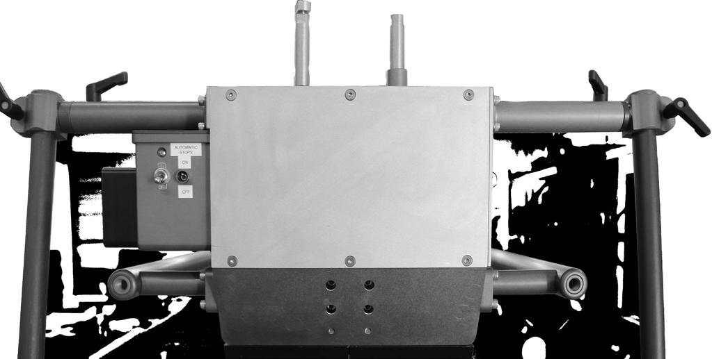
2 Shipping and Storing the Miniscope 45 2 It is Chapman/Leonard s goal to provide the best camera support equipment with exceptional Customer Service. For any questions regarding this User Guide please contact Customer Service at or Chapman / Leonard Certified Locations: MAIN OFFICE: California Raymer Street, North Hollywood, CA Toll Free: Fax: Rentals Leasing Accounting UK and Europe Phone: Fax: The Minibase Steering Handles are extendable, and designed to stabilize the arm and prevent unwanted movement of the Miniscope during shipping and storage. Follow the steps below to safely prepare the Miniscope for shipping and storage Attach the locking bar. Attach the arm locking pin. Locking Bar Mount the Miniscope on to the Minibase. First, secure the Minibase chassis with straps fastened around the frame. Second, secure the Minibase with straps fastened around the top of the center post column. Use caution to prevent over tightening of ratchet straps! Secure the weight bolts before shipping the Miniscope to prevent weights from unwanted movement during transportation. Use a wrench to ensure sufficient tightness. 1 3 Minibase Louisiana Toll Free: Fax: Texas Toll Free: Fax: New Mexico Toll Free: Fax: **WARNING** USE OF RATCHET STRAPS MAY DAMAGE EQUIPMENT IF OVER- TIGHTENED. USE RATCHET STRAPS WITH CARE. RATCHET STRAPS TO SECURE THE TELESCOPING ARM SHOULD BE SECURED AT THE DESIGNATED POINTS AND ARE NOT TO EXCEED 50 LBS TENSION. SEE ILLUSTRATION BELOW. Lines around the Chassis should be secured to 100 LBS Tension. Georgia Toll Free: Fax: Florida 9460 Delegates Drive Orlando, FL Toll Free: Fax: LBS *Apply Lines Here 50 LBS 100 LBS 4 For updated postal addresses of our locations, please visit our website at and in the UK and Europe at LBS 50 LBS *Apply Lines Here 50 LBS 5 5 *Apply Lines Here NOTE: Safety lines to secure the unit in the event of emergency stops. Apply lines at the top of the center post column and the frame of the chassis. Do not over-tighten. 4
3 Shipping the Miniscope The Miniscope must be properly crated before shipment (see next page). Make sure to attain a signed receipt from your chosen transport company to confirm shipment. Rental bays are located on the left, immediately after entering the Chapman / Leonard facility. Trucks should be backed into the bays for easier loading. If no bays are available, please park on Raymer Street and advise the Rental Office of your arrival. A customer service agent will notify you once a space becomes available. All drivers must report to the rental office to process paperwork before loading/unloading may begin. Our Rental Staff is well trained to process equipment and documents efficiently. 405 RAYMER ST. 210 COLDWATER CYN. SHERMAN WAY 170 *ALL RENTALS must be Returned by 10:00 AM, Pick-ups 2:00 PM to close. Rental Office Hours: Monday - Friday: 7:00 AM 6:00 PM Saturday: 8:00 AM 12:00 PM Sundays: CLOSED **WARNING** DO NOT USE RATCHET STRAPS TO TIE DOWN THE MINISCOPE AS IT MAY STRESS THE ARM. RATCHET STRAPS MAY ONLY BE USED ON THE MINIBASE CHASSIS. Chapman / Leonard Studio Equipment, Inc. Main Office: Raymer Street North Hollywood, CA MINISCOPE 02 Miniscope Features and Specifications 03 Quick Start Key 04 Miniscope 7 Specifications on the Minibase 05 Miniscope 7 Specifications on the Hybrid IV Dolly 06 Detailed Miniscope 7 Specifications on the Hybrid IV Dolly 08 Miniscope 7 Specifications on the Ultra Hy Hy Base 09 Miniscope Alternate Positions 11 Miniscope Telescoping Zoom Shot 12 Miniscope Head Offset Accessory 13 Mounting the Miniscope: Featured on the Hybrid IV Dolly 15 Castle Ring Application 16 Electric System Connections 18 Joystick Connector and Controls 19 Balancing the Miniscope 22 Leveling the Nose 23 Overslinging and Underslinging the Nose PREPARING A BASE 26 Leveling the Minibase 27 Installing the Nose Strut and Leveling the Hybrid IV Head 28 Leveling the Ultra Hy Hy and Hy Hy Base SAFETY IN USE 29 Important Safety Features 30 Safety in Use and the Inertial Effect 32 Troubleshooting 33 Minibase Features 34 Minibase Specifications 35 Minibase Automated Steering 36 Minibase Universal Handle 37 Minibase on Track and Off-Road Tire Configuration 38 Using the Minibase on Curve Track 41 Minibase Use on Grade 42 Equipment Care and Cleaning 44 Shipping the Miniscope 45 Shipping and Storing the Miniscope Contents 01 MINIBASE EQUIPMENT CARE AND SHIPPING INSTRUCTIONS
4 02 Miniscope Features and Specifications Notes 43 The Miniscope is a light-weight, user friendly Telescoping arm that has been designed to be used on our specially designed Minibase as well as our Ultra Hy Hy base, Hybrid IV and Hustler camera dollies. The Miniscope can be operated by one person, and may or may not require the assistance of a highly trained technician. This manual will instruct you on how to effectively set up and operate the Miniscope. Trim Weight Bucket (primary) Automatic Electronic Stops Mechanical Soft Stop Leveling Head Assembly Trim Weight Bucket (secondary) Rear Bucket Handle Sliding Fine- Tuning Weight Arm Locking Pin Arm Locking Pin Storage Locking Bar Side Rail Pan Friction Handles Tilt Friction Handle Weight Carriage Mitchell Mount Miniscope Overview Power: The Miniscope and Minibase are electrically powered by a 30v Chapman Battery or AC/DC converter. Weight Carriage: acts as a counter-balance to the nose payload as it slides along the column. The tray moves forward when the arm is retracting, and the tray slides back when the arm is extending. Trim Weight Bucket: The bucket is located in the rear of the Miniscope and is where trim weight is applied in the balancing process. Sliding Fine-Tuning Weights: Are adjusted by loosening the Knurled Knobs, sliding the weight, and tightening the knob again. These are used for fine-tuning the balance when balancing the Miniscope. Mitchell Mount: The nose is located at the very front of the Miniscope. This is where the head and camera are mounted to the Mitchell Mount. Pan Friction Handle: is designed to minimize float on still shots when the Miniscope is balanced. It is not intended as a safety brake for walking away or shipping. Tilt Friction Handle: is designed to minimize float on still shots when the Miniscope is balanced. It is not intended as a safety brake for walking away or shipping. The Locking Bar: is located underneath the arm. This locks the arm in the horizontal position. The bar needs to be locked in place when the Miniscope is being balanced. The pin will create play where the locking bar meets the arm to aid in the balancing of the Miniscope. When the locking bar floats on the pin the Miniscope is balanced. **WARNING** DO NOT REMOVE LOCKING BAR WHEN MINISCOPE IS OUT OF BALANCE. DO NOT USE RATCHET STRAPS TO TIE DOWN AS IT MAY STRESS THE ARM. The Arm Locking Pin: This is located toward the back of the arm (on the right side when looking toward the front of the Miniscope), in front of the bucket. The pin will lock the Miniscope arm in the retracted position to disable the telescoping function. **WARNING** THE LOCKING PIN SHOULD REMAIN IN THE ARM WHEN BEING TRANSPORTED OR NOT IN USE! Automatic Electronic Stops: provide feathered stops when reaching the end of the extension or retraction. Mechanical Soft Stops: Provides a secondary stop to prevent a mechanical hard stop at the extreme limits of the arm.


 Hustler IV Dolly 2 Mount the Miniscope Spray the tires with Zep Par NC Silicone Spray (Key Words on Label are")
5 42 Equipment Care and Cleaning Quick Start Key 03 1 Choose a Base Always begin cleaning the equipment with a Vacuum Cleaner. Never use an air hose, because dirt and metal shavings will find their way into joints and bearings. This can seriously shorten the life of the equipment. Use soap and water applied to a cloth or paper towel, or preferably a brush to wipe down the rubber and metal parts of the equipment. Never directly spray the equipment with water. For Rubber and Plastic For Metal Within each can of Silicone Spray, we provided a sponge to prevent harmful vapor exposer when used indoors. Spray the Silicone solution onto the sponge, then quickly wipe the desired area. **WARNING** HARMFUL VAPOR. CAN CAUSE EYE, SKIN AND RESPIRATORY IRRITATION. ALSO READ PRODUCT LABEL FOR FURTHER INSTRUCTIONS. Wax the exterior of the equipment using Megular s Mirror Glaze Cleaner Wax. This keeps the Equipment cleaner during regular use and preserves the finish. Clean equipment will ensure optimum performance with smooth and quiet movements, while enhancing its aesthetics. Minibase (Delivery System) Hustler IV Dolly 2 Mount the Miniscope Spray the tires with Zep Par NC Silicone Spray (Key Words on Label are Mold Release Agent ). This dramatically improves Tire Performance on Tile Floors, Hardwood, Track and even on Concrete. Use the same spray to clean the Tires. Must apply Silicon Spray while wet for best results. NOTE: When dolly is in use on a curved track to prevent dolly from derailing use ZEP Silicone Spray. 3 Choose a Remote Head Chapman CL Head with Red Camera Hybrid IV Dolly 4 Choose a Power Source v AC/DC converter Chapman/Leonard DC Battery
 Maximum Payload 150 lbs Telescoping Travel 6 ft 9 in Min Reach From Fulcrum 4 ft 8 in Max Reach From Fulcrum 11 ft 4 in Max Telescoping Travel Speed 3.")
 3 8 (1.1m) 58.50 6 6 (2.0m) Friction Brake 7 4 (2.24m) 3 2 4 1 (1.24m) (1.0m) 14 8 (4.")
6 Miniscope 7 Specifications on the Minibase 04 Minibase Use on Grade Steering Lock Pin 3 (0.9m) Maximum Payload 150 lbs Telescoping Travel 6 ft 9 in Min Reach From Fulcrum 4 ft 8 in Max Reach From Fulcrum 11 ft 4 in Max Telescoping Travel Speed 3.5 ft/sec Max Weight Fully Loaded 780 lbs Weight: Arm NO Payload 285 lbs Weight: Arm Stripped 225 lbs Shipping Weight 800 lbs Electrically Powered 30 volts Power Source : AC/DC Converter or Battery Vertical Travel on Minibase 16in Base Weight 230 lbs 9 1 (2.77m) 3 8 (1.1m) (2.0m) Friction Brake 7 4 (2.24m) (1.24m) (1.0m) 14 8 (4.47m) Underslung Retracted When moving up or down a grade, lock the rear axle and partially engage the rear friction brake. 2 Steer uphill for maximum control (3.99m) (1.7m) (0.6m) (5.44m) 12 3 (3.73m) Underslung Extended 10 7 (3.23m) (3.3m) Bucket to Nose Nose Section (0.4m) 16 3 (4.95m) The friction brake can be partially applied for controlled movement of the base, or completely locked off for a stationary shot. Overslung Retracted 5 10 Overslung Extended (1.8m) Bucket to Fulcrum 4 8 (1.4m) Fulrcum to Mitchell Mount Horizontal Retracted Horizontal Extended 7 0 (2.13m) Top of Crane to Mitchell Mount (1.65m) (0.6m) (1.57m) Ground to top of Bucket (0.84m) Ground to Base Mount (1.07m) 1 11 (0.58m) (1.78m) (3.45m) Fulcrum to Mitchell Mount Bucket to Fulcrum Ground to Mitchell Mount 2 1 *Miniscope mounted on a Minibase with CL Stabilized Head. Measurement from lens to Mitchell Mount approx. 20. Lock the steering handle/axle and gradually apply friction brake for maximum control.

 Maximum Payload 150 lbs Telescoping Travel 6 ft 9 in Min Reach From Fulcrum 4 ft 8 in Max Reach From Fulcrum 11 ft 4 in Max Telescoping Travel")

 17 4 58.")
 Overslung Extended IV Do not remove nut on fixed wheel unless converting to 880mm track.")
7 40 Miniscope 7 Specifications on the Hybrid IV Dolly Using the Minibase on Curve Track Continued Wheels to be used on the outside curve of the track are marked with blue paint on the inside hub of the wheel and axle. These wheels contain DU bushing and will articulate to accommodate the curve. (1.7m) Maximum Payload 150 lbs Telescoping Travel 6 ft 9 in Min Reach From Fulcrum 4 ft 8 in Max Reach From Fulcrum 11 ft 4 in Max Telescoping Travel Speed 3.5 ft/sec Max Weight Fully Loaded 780 lbs Weight: Arm NO Payload 285 lbs Weight: Arm Stripped 225 lbs Shipping Weight 800 lbs Electrically Powered 30 volts Power Source : AC/DC Converter or Battery Vertical Travel on Hybrid IV 3ft 8in Base Weight 463 lbs The fixed wheels that are to be used on the inside curve of the track are unmarked. These wheels are fixed and should be kept on the brake side (5.8m) inches of travel (5.3m) (0.6m) HY BRID 13 3 (4.0m) (3.6m) Overslung Extended IV Do not remove nut on fixed wheel unless converting to 880mm track. IV *Miniscope mounted on a Hybrid IV dolly with CL Stabilized Head. Measurement from lens to Mitchell Mount approx. 20. HY BRID 6 6 (2.0m) 3 (0.9m) Twist to engage/disengage the Friction Brake Overslung Retracted Before coming off the track, re-secure the nut and safety nob (4.8m ) 3 8 (1.1m) 10 1 (3.1m) Friction Brake (4.3m) 8 5 (2.6m) (1m) 5 2 (1.6m) 1 7 (0.5m) 4 5 (1.3m) Underslung Retracted Underslung Extended


8 06 Detailed Miniscope 7 Specifications on Hybrid IV Dolly Using the Minibase on Curve Track Continued 39 The Miniscope can be used on a variety of shots and locations. The Miniscope can be mounted on the Hybrid IV Dolly to be used for low shots at the edge of a stage, boat dock, street etc, as well as curved track. With the Hybrid IV Underslung, arm boomed to the lowest point and the Miniscope fully extended, the lens can be lowered below ground to 8 feet. On the Hybrid IV the operator can achieve a vertical travel of 22 feet 2 inches with the combined movement of the dolly arm lift and vertical arm tilt. Measurement to Ground 5 Lubricate the concave track groove on the Minibase Tires using the sponge provided with Zep Par Mold Release Spray. The Miniscope is set in the UNDERSLUNG position using Chapman/Leonard s CL Stabilized Head (5.11m) 6 The Minibase is ready to be used on curve track (4.80m) Measurement to Ground 12 0 (3.66m) 10 1 (3.10m) 11 1 (3.39m) 12 0 (3.66m) 14 2 (4.32m) (53 ) 8 5 (2.57m) (53 ) 7 7 (2.31m) 2 0 (0.61m) (58.5 ) Underslung Retracted HYBRID IV 0 6 (0.15m) 1 1 (0.33m) 2 6 (0.76m) 4 4 (1.32m) 5 11 (1.80m) 7 7 (2.31m) 2 0 (0.61m) (58.5 ) Underslung Extended HYBRID IV Hybrid IV arm lowered 1 7 (0.48m) 5 2 (1.57m) (4.85m) 2 10 (0.86m) 3 9 (1.14m) 4 4 (1.32m) Outside set of wheels with DU bushing (3.30m) Bucket to Nose Top of Crane to Mitchell Mount 1 5 (0.43m) Nose Section 8 5 (2.57m) (53 ) 11 4 (3.45m) Measured Below Ground Fulcrum to Mitchell Mount 4 5 (1.35m) 4 11 (1.50m) 5 10 (1.78m) Bucket to Fulcrum 2 1 (0.64m) 4 8 (1.42m) Fulcrum to Mitchell Mount 0 9 (0.23m) 2 4 (0.71m) 4 2 (1.27m) For full arm swing clearance, remove the tracking bar and steering column. 1 7 (0.48m) 2 4 (0.71m) 0 2 (0.05m) 6 5 (1.96m) 0 9 (0.23m) 8 0 (2.44m) Measured Below Ground 8 6 (2.59m)


 9 8 (2.31m) (2.95m) 5 2 Blue paint on axle hub and wheel hub. 4 0 (1.22m) 2 0 (0.89m) (1.")
 (2.")
 7 10 7 7 Blue Paint 4 (53 ) (53 ) Be sure the wheels equipped with the DU bushing are on the outside curve side of the Minibase.")
 (0.05m) Overslung Extended Overslung Retracted 10 10 Measured 1 5 Belo w (0.43m) Ground 2 6 8 6 (3.30m) Bucket to Nose (0.")
 1 5 (0.43m) Nose Section Screw in Safety End Cap here 1.")
9 Using the Minibase on Curve Track Detailed Miniscope 7 Specifications on Hybrid IV Dolly Before preparing the Minibase for curve track, roll the Minibase on to straight track using starter track and remove the pneumatic tires. The Miniscope pictured in the Overslung position giving the operator more height. The lens is at 18 feet and 11 inches with the Hybrid IV arm boomed to its highest point with a fully extended Miniscope. On the Hybrid IV the operator can achieve a vertical travel of 22 feet 3 inches with the combined movement of the dolly arm lift and vertical arm tilt. (NOTE: Be sure that the steering handle is perpendicular to the axle before resetting steering lock.) Measurement to Ground The Miniscope is set in the OVERSLUNG position using Chapman/Leonard s CL Stabilized Head. Pull and twist the Steering Lock Pin on both sides of the Minibase to release both steering handles (5.77m) 17 4 Measurement to Ground (5.28m) Steering Lock Pin 13 3 (4.04m) 11 8 (3.56m) (3.66m) (3.66m) 9 6 (2.90m) (58.5 ) 9 8 (2.31m) (2.95m) 5 2 Blue paint on axle hub and wheel hub. 4 0 (1.22m) 2 0 (0.89m) (1.57m) 8 1 Hybrid IV arm lowered HY BRID IV IV (1.57m) (0.61m) Remove the 1 nut from the axle using a speed wrench. Screw the safety end cap into the threaded axle to allow the DU bushing to slide on the axle as it enters the curve. 7 7 (2.39m) (2.31m) DU Bushing (58.5 ) Blue Paint 4 (53 ) (53 ) Be sure the wheels equipped with the DU bushing are on the outside curve side of the Minibase. The wheels with the DU bushing are marked with blue paint on the inside hub of the wheel. HY BRID 3 (0.61m) (2.46m) (0.48m) (0.05m) Overslung Extended Overslung Retracted Measured 1 5 Belo w (0.43m) Ground (3.30m) Bucket to Nose (0.76m) (2.59m) 11 4 (3.45m) Fulcrum to Mitchell Mount 5 10 (1.78m) (53 ) Top of Crane to Mitchell Mount 5 10 (1.78m) 2 1 (0.64m) 1 5 (0.43m) Nose Section Screw in Safety End Cap here 1.5 Speed wrench Safety Cap in place Safety End Cap As the outside wheels enter the curve, the DU bushing will slide on the threaded axle (1.78m) Bucket to Fulcrum (1.27m) 4 3 (1.30m) 4 8 (1.42m) Fulcrum to Mitchell Mount For full arm swing clearance, remove the tracking bar and steering column. (1.30m) 1 7 (0.48m) 3 4 (1.02m) 4 11 (1.50m) Measured Below Ground 6 1 (1.85m)
10 08 Miniscope 7 Specifications on the Ultra Hy Hy Base Minibase on Track and Off-Road Tire Configurations 37 Maximum Payload Telescoping Travel Min Reach From Fulcrum Max Reach From Fulcrum Max Telescoping Travel Speed Max Weight Fully Loaded Weight: Arm NO Payload Weight: Arm Stripped Shipping Weight Electrically Powered 150 lbs 6 ft 9 in 4 ft 8 in 11 ft 4 in 3.5 ft/sec 780 lbs 285 lbs 225 lbs 800 lbs 30 volts Power Source : AC/DC Converter or Battery Vertical Travel on Ultra Hy Hy 15.5in Base Weight 500 lbs 5 5 (1.7m) (5.4m) The standard tires for the Minibase are hard rubber tires designed for track and flat surfaces. The Minibase can be used on both standard 24.5 track (Fig. A) and 880mm track with extensions (Fig. B). WARNING: Friction brakes will not activate on 880mm track. Note: 880mm Brake extensions and axle extensions are included. A B *Miniscope mounted on a Ultra Hy Hy Base with the CL Stabilized Head. Measurement from lens to Mitchell Mount approx (0.6m) (3.2m) 12 1 (3.7m) Overslung Extended 6 6 (2.0m) 16 2 (4.9m) Soft pneumatic tires are available with an adapter, and will allow the Minibase to be used on sand and other off-road surfaces. For Example: If there is a tracking shot on a beach, the pneumatic tires will act as transport wheels, and the base can simply be rolled onto the 24.5 track. (The pneumatic tires are slightly larger than the hard tires.) C 3 8 (1.1m) 3 (0.9m) (1.0m) 4 (1.2m) Overslung Retracted 7 3 (2.2m) 8 11 (2.7m) (4.0m) 14 7 (4.4m) Within each can of Silicone Spray, we provided a sponge to prevent harmful vapor exposer when used indoors. Spray the Silicone solution onto the sponge, then quickly wipe the desired area. **WARNING** HARMFUL VAPOR. CAN CAUSE EYE, SKIN AND RESPI- RATORY IRRITATION. Spray the tires with Zep Par NC Silicone Spray (Key Words on Label are Mold Release Agent ). This dramatically improves Tire Performance on Tile Floors, Hardwood, Track and even on Concrete. Use the same spray to clean the Tires. Must apply Silicon Spray while wet for best results. NOTE: When base is in use on a curved track to prevent dolly from derailing use ZEP Silicone Spray. Underslung Retracted Underslung Extended


11 36 Minibase Universal Handle Accessory Miniscope Alternate Positions 09 Position 1 - Standard Position The Minibase Handle Adapter allows the Minibase Handle to be used on any Chapman dolly, including the Hybrid IV and Hustler IV camera dollies, as well as the Ultra Hy Hy and Hy Hy bases. The handle is designed to be put up or down so that the Miniscope has room to move 360 around the chassis Adjustable Fulcrum 4 8 The Miniscope Alternate Positions are easy to achieve by removing a few bolts from the adjustable fulcrum. These positions are used to shorten the rear section of the Miniscope for tight spaces Position An estimated lbs must be added as counterweight in this configuration. Adjustable Fulcrum Handle Adapter The Handle Adapter shifts the dolly into crab or conventional steering while using the Minibase Handle. Shorter Rear Section More Reach


12 10 Miniscope Alternate Positions Position 2 Position 1 Minibase Automated Steering Make sure the Miniscope is retracted, and that the Column Locking Pin is in place. Using Apple Boxes or Stands to support both ends of the Miniscope as illustrated. Avoid putting weight on electric cables. Remove all 12 Screws, 6 from both sides of the sliding plate. Remove the Locking Bar. Use caution when removing the locking bar, and support the arm for any imbalance. Support the Miniscope arm and Push the Minibase to move the fulcrum to the alternate position as illustrated. Install all 12 Screws, 6 on each side. Add appropriate counter weight-up to 130 lbs to balance the Miniscope. To test the balance raise center post slightly. Add or remove weight as necessary. Position 2 Screws *USE CAUTION* SCREWS MUST BE REPLACED CORRECTLY TO AVOID DAMAGING THE EQUIPMENT. FULCRUM PANEL SCREWS Position 1 3 1/2 Black Alloy Screws 3/8 Silver Stainless Steel Screws The Linear Actuator allows the Minibase steering to be done remotely from either side of the base. The Linear Actuator is by special request only. Steering Linear Actuator Accessory Actuator Switch Accessory Minibase Push Handle Push Handle 9 10 Install the locking bar. When the Miniscope is balanced you may remove the support stands. Sliding Adjustable Fulcrum 5 The actuator can be removed using two knobs NOTE: The steering handle and Linear Actuator are NOT to be used together. Remove Linear Actuator before using steering handle. 20 x 12 x 8 Apple Boxes x 12 x 8 Apple Boxes *USE CAUTION* APPROPRIATE COUNT- ER WEIGHT MUST BE ADDED BEFORE REMOVING LOCKING BAR.


13 Top View Minibase Specifications 13 Soft Pneumatic tire extensions ITEM #: Miniscope Telescoping Zoom Shot 11 The Miniscope has the ability to perform a horizontal plane or linear shot without having to adjust the boom. This shot can be achieved from 9 3 above the ground to 7 from the ground when mounted on the Hybrid Dolly for a dynamic range of v POWER SOURCE: 1 Chapman Battery and AC/DC Converter will power the telescoping arm, camera system and electronic lift of the Minibase. The Batteries and Converter also act as weights for the base to lower the center of gravity. The system can be controlled manually or remotely by a single operator *The distance from the center line to the lens is MINISCOPE 75 FEATURED ON THE MINIBASE NOTE: The Minibase can be equipped with a remote linear actuator and/or remote control steering for an additional cost.


14 12 Miniscope Head Offset Accessory There is no front or back on the Minibase. The Head Offset Accessory offsets the payload, aligning the center of gravity with the column. This allows for a more compact configuration and improved performance when telescoping in and out. Minibase Features 33 Minibase Deck This flat surface is useful for keeping cables and cords organized. Removable Steering Base Handle. The handle can be removed and used with the Hybrid IV camera dolly. Steering bar release pin. Pull and twist to disengage. Twist till pin drops into receiver to re-engage. Lower CG 3 3/8 3 3/8 Higher CG Soft Pneumatic Tires Accessory Weight Storage stores the bucket trim weight and carriage weights. Chapman Battery and AC/DC Converter Battery Hooks are designed for holding Chapman Batteries, or AC/DC converters that will power the Minibase Lift, as well as the Miniscope arm and nose. Actuator Switch moves the Minibase center post up and down with 16 of travel. Up Down Actuator Switch Input/Output 3-Pin 30v XLR Output Cable to Battery 3-Pin 30v XLR Input Cable to Actuator NOTE: The Minibase can be equipped with a remote linear actuator and/or remote control steering for an additional cost.
 Connect main power source and apply power.")
 Turn on the Miniscope main power switch located at the rear of the arm.")
 Set the speed control to the center position located on the joystick.")
 Turn on the leveling head power switch located on the leveling head.")

 The arm is drifting in or out. A) Extend or retract the arm so the weights are over the fulcrum.")
 Please note that the arm may drift (push back) at the extreme stops in order to prevent damage to")


15 32 Troubleshooting Mounting the Miniscope : featured on the Hybrid IV Dolly 1) The Miniscope will not telescope when activating the Joystick Control. A) Connect main power source and apply power. B) Remove the safety locking pin from the rear of the Miniscope arm. C) Turn on the Miniscope main power switch located at the rear of the arm. D) Turn on the secondary power switch located on the joystick. E) Set the speed control to the center position located on the joystick. A) Connect main power source and apply power. B) Turn on the leveling head power switch located on the leveling head. C) Adjust the leveling head potentiometer to achieve proper level. Before the leveling head is adjusted make sure the post on the base is level. D) Make sure the underslung/overslung switch is in the correct position. 3) The arm is drifting in or out. A) Extend or retract the arm so the weights are over the fulcrum. Adjust the drift knob located on the joystick control. B) Please note that the arm may drift (push back) at the extreme stops in order to prevent damage to the motor assembly. You may use the enable/ disable power switch feature located on the joystick to prevent drift. The Miniscope can be mounted on Chapman/Leonard s Hybrid IV Camera Dolly, as well as other Mitchell Mount bases. On a camera dolly the Miniscope has greater vertical travel, including the ability to go below ground. Miniscope Main Power Switch Weight Bucket Weight Carriage Fully Retracted Miniscope Secondary Arm Power Switch (Disable/Enable) Locking Pin 0 2) The leveling head is not level Speed Leveling Head Potentiometer Adjustment **WARNING** THE LOCKING PIN SHOULD REMAIN IN THE ARM WHEN BEING TRANSPORTED OR NOT IN USE! Locking Bar Pan Friction Handles Engaged **WARNING** DO NOT REMOVE LOCKING BAR WHEN MINISCOPE IS OUT OF BALANCE **WARNING** INSTALL DOLLY NOSE STRUTS BEFORE MOUNTING THE MINISCOPE Leveling Head Power Switch 1 Remove all weights from the bucket of the Miniscope to make as light as possible. 3 Level the Hybrid IV Mitchell Mount. 2 Remove all the weights from the sliding weight tray. Leveling Bubble Drift Adjust drift until Miniscope is stationary. To completely eliminate drift, turn off the Miniscope main power or secondary arm power switch. NOTE: The dolly leveling head should always face toward the center of the chassis to ensure stability when operating the Miniscope. Leveling Head Nose Struts


16 Mounting the Miniscope : featured on the Hybrid IV Dolly Cont Carry the Miniscope fully retracted with locking bar and locking pin in place. (See page 03) The Miniscope can be safely carried between 4 people Place Miniscope on to the Mitchell Mount of the Hybrid IV, or other base and line up the keyway. NOTE: When securing Miniscope onto the Mitchell Mount make sure that the pan friction handles are fully engaged. *Caution* the rear section of the Miniscope is heavier, support any imbalance in weight. Safety in Use and the Inertial Effect Continued *CAUTION* The Miniscope and Dolly system should be handled in this area to avoid a tip-over when pushing the dolly. Pan Friction Handles 6 There are six places for the push bar. The push bar can be used anywhere to avoid being in the way of the arm/camera operator. Once the Miniscope is placed on the mount, continue to support the rear of the Miniscope, and attach the Mitchell Nut. Hand-tighten, then using the Hybrid Mitchell Nut Wrench to tighten fully. *CAUTION* SUPPORT THE WEIGHT OF THE MINISCOPE UNTIL THE MITCHELL NUT IS INSTALLED, WITH THE KEYWAY LINED UP, AND FULLY TIGHTENED. Mitchell Nut Mount the Miniscope on the Hybrid Dolly: LABOR FREE 1 Make sure the Miniscope is retracted, and that the Column Locking Pin is in place. Orient the Miniscope perpendicular to Minibase Using Apple Boxes or Stands to support both ends of the Miniscope as illustrated. Avoid putting weight on wires. 4 Remove Mitchell Nut and Lower Column Post. 20 x 12 x 8 Apple Boxes 2 **WARNING** Pushing, pulling or stopping at the base of the chassis should be avoided. 8 After Lowering the Column Post roll the base away. 12 Roll the Hybrid Dolly into place, Raise the Arm on the dolly carefully into place and Attach the Mitchell Nut.


. Hybrid Castle Ring and Wrench 5.")

17 Safety in Use and the Inertial Effect 30 Castle Ring Application 15 The Castle Ring Wrench is compatible with Castle Nuts - both circular and square pegs. The Castle Ring Wrench attaches to the bottom of the Miniscope when the Miniscope is placed on the base. Hand-tighten, then cinch down with a wrench. The Miniscope can be used safely by following these tips to neutralize the inertial effect. Inertial Effect: When the Miniscope is fully extended and the dolly arm is up, there is increased torque on the base of the system due to momentum. (As shown in Figure A.) A Castle Rings Loosen For safe use refer to these tips: 1. The Push rod should be fully extended The Push Rod should be pushed at the top by the handle Hybrid Crab Mode with legs in the 45 position Fig. A Tighten 3. The Battery, AC/DC converter or sandbags should be placed on the back of the dolly to ad weight to the base. 4. When used in crab mode for lateral movement, the dolly legs should be swiveled out to widen the base (fig. A). Hybrid Castle Ring and Wrench 5. Always perform a test run to determine safety in movement before actual shooting takes place. Insert pins into opposing holes in the ring, insert rod in the slot and twist to tighten ring. Avoid over-tightening. Hybrid Dolly Wheels should be positioned at the 12 or 45 position for maximum stability and safety. If the Castle Ring Wrench is unavailable: Use a hammer and rod to tap the castle ring tight. Be careful not to break pins or damage equipment. Standard 12.9 Track 45


18 16 Electric System Connections Secure wires from battery and base between yellow lines on the side rail with velcro to maintain balance and avoid over-stretching the wires. Important Safety Features 29 **WARNING** ALWAYS TEST SAFETY IN MOVEMENT BEFORE RUNNING A SCENE WITH ALL ACTORS, SET AND CREW IN PLACE. Miniscope mounted on the Minibase. The Miniscope is a light-weight, user friendly Telescoping arm that has been made to be used on our specially designed Minibase as well as our Ultra Hy Hy base, Hybrid IV and Hustler camera dollies. The Miniscope can be operated by one person, and may or may not require the assistance of a highly trained technician. This manual will give you all you need to know to effectively set up and operate the Miniscope. IMPORTANT INFORMATION WHEN USING THE HYBRID IV DOLLY Arm Power Cord Nose Power Cord Miniscope Arm and Minibase powered by 30v Chapman/Leonard Battery or AC/DC Converter. Minibase Deck This flat surface is useful for keeping cables and cords organized. The Nose Struts: Must be attached to the nose of the Hybrid IV dolly. Position the Nose of the Hybrid IV toward the center of the dolly. This will ensure maximum safety and stability when operating the Miniscope. Roller Guides and Rails: Must be kept clean. Wipe with a clean rag. Miniscope and Minibase powered by: and v AC/DC converter 30v Output v AC Power Cord 3 Interchangeable power sources for: 30v Electric Center Post Lift 30v Miniscope Leveling Nose 30v Miniscope Telescoping Arm Chapman/Leonard DC Battery Charge Port 30v Output 24v Output Switchable Output 12v/24~30v 12v Output Charge battery when Digital Voltage Display reads below 29v. Hybrid Dolly Wheels should be positioned at the 12 or 45 position for maximum stability and safety. Standard 12.9 Track 45 Chapman Battery or AC/DC converter should be placed toward the back of the dolly to maintain maximum stability. Both the AC/DC converter and Battery come with the Miniscope standard package. Added weight at this point will add stability in the Miniscope / Hybrid configuration.


19 Electric System Connections Continued Leveling the Ultra Hy Hy and Hy Hy Base *CAUTION* THE MOUNT SHOULD BE LEVELED BEFORE AND AFTER MOUNTING THE MINISCOPE, AS WELL AS AFTER ANY SIGNIFICANT AMOUNT OF TRAVEL. Line the pocket level up with bars you wish to level. Turn the leveling bars in opposite directions (and in unison) to observe the way the Hy Hy post moves. Adjust plane using the leveling bars until the bubble is centered. Repeat process using remaining set of bars. Leveling the Ultra Hy Hy Miniscope Main Power Switch Turn In Unison Miniscope should be powered off when used manually. Automated Stop Power Switch (Disable/Enable) Level TO ELIMINATE DRIFT ON LONG LOCK OFF SHOTS, POWER OFF THE MINISCOPE. Joystick Cable Connector Joystick Controller There are switches on the back of the Miniscope and on the Joystick. Leveling the Hy Hy Base Leveling the Hy Hy is easy with leveling bubbles attached to the post. Turn the leveling bars in opposite directions (and in unison) to observe the way the Hy Hy post moves. Adjust plane using the leveling bars until the axis appears level according to the bubble. Repeat process using remaining set of bars. The mount should be leveled before and after mounting the Miniscope, as well as after any significant amount of travel. Miniscope Power Connector Leveling Head Potentiometer Adjustment Power Indicator Light Leveling Head Motor Power Connector Leveling Head Power Switch Leveling Head Potentiometer connector


 to observe the way the Mitchell Mount moves.")


 Use Arm")


20 Joystick Connector and Controls 18 Installing the Nose Strut and Leveling the Hybrid IV Head Joystick Installing the Nose Struts *CAUTION* Avoid frequent connecting and disconnecting to minimize damage to pins and key-way. 1 Line up Key-way on Joystick Connector Before leveling the Mitchell Mount, or mounting the Miniscope, the Nose Struts must be attached. The dolly leveling head should always face toward the center of the chassis to ensure stability when using the Hybrid IV dolly. The operator should position himself in front of one of the built-in window levels. Turn the leveling knobs in opposite directions (and in unison) to observe the way the Mitchell Mount moves. Adjust the Mitchell Mount until the bubble is centered. Repeat process using remaining set of knobs. *CAUTION* THE MOUNT SHOULD BE LEVELED BEFORE AND AFTER MOUNTING THE MINISCOPE, AS WELL AS AFTER ANY SIGNIFICANT AMOUNT OF TRAVEL. Drift 0 Secondary Arm Power Switch (Disable/Enable) Use Arm Power Disable Switch to completely eliminate drift for stationary shots. Arm In Power Indicator Light Dampening / Feathering Nose Struts When the Miniscope is placed on the Indexed GQ Leveling Head, the head must be leveled to avoid unleveled images when filming. Note: Colored Tags make it easy to line up key-ways and connections. Arm Out Leveling Head Leveling the Hybrid IV Head Insert and Turn Clockwise 2 27 Built In Window Level 100 Adjust drift until Miniscope is stationary. To completely eliminate drift, turn off the Miniscope main power or secondary arm power switch. Speed Level Axis One Level Axis Two

 to observe the way the post moves.")
 And connect the power cables.")


21 26 Leveling the Minibase Balancing The Miniscope *CAUTION* THE MINISCOPE ARM SHOULD BE LEVELED BEFORE AND AFTER MOUNTING THE MINISCOPE, AS WELL AS AFTER ANY SIGNIFICANT AMOUNT OF TRAVEL. 1 The Crane must be balanced before use. The nose payload must be present before you can achieve a properly balanced arm. To Level the Minibase use the built-in levels. Turn the leveling bars in opposite directions (and in unison) to observe the way the post moves. Adjust posts using the leveling bars until the axis is level according to the bubble. Repeat process on opposite axes. 2 With the Locking Bar in place for safety, apply Nose Payload. (Head, camera and accessories.) And connect the power cables. 19 NOTE: The Nose Payload includes the camera, head attachment, and any accessories. If extra accessories are added, or if the head is Overslung or Underslung the arm must be re-balanced. Built-In Level 3 Remove the arm locking pin. This will allow the operator to move the weight tray to the center fulcrum of the Miniscope. The Locking Bar should remain in place. 4 With the power off, Manually move Weight Carriage to center of fulcrum. Monitor Weight Carriage to ensure that it stays over the fulcrum through step 5. Trim Weight Bucket Miniscope Main Power Switch Level Axis 1 Arm Locking Pin Sliding Fine Tuning Weights Weight Carriage Level Axis 2 *Rotate in opposite directions and turn in unison. *3/8 inch slot allows the locking bar to move freely within the range of the slot, allowing the operator to feel the change in balance. Locking Bar Fulcrum Center Tilt Friction Handles


22 20 5 First release the Tilt Friction Handle. Then add Bucket Trim Weights until the Miniscope feels balanced on the 3/8 inch slot*. When the Miniscope floats on the 3/8 slot, the Miniscope should be balanced. It is important to keep the Weight carriage over the fulcrum during this step. **WARNING** ALWAYS SECURE WEIGHTS WITH SPACERS AND WING NUTS. *3/8 inch slot allows the locking bar to move freely within the range of the slot, allowing the operator to feel the change in balance. 6 Overslinging the Nose Continued Balancing The Miniscope Continued release 25 7) Re-tighten the 1 inch Leveling Head Nut. The nut should be snug, use care to prevent over tightening. *CAUTION* LEVELING HEAD NUT: SNUG TIGHT, DO NOT OVER TIGHTEN. Leveling Head Nut: Snug tight, do not over tighten. 8) Double check nose level and re-adjust the leveling head if necessary. Primary Trim Weight Bucket Balance the Weight Carriage to achieve dynamic balance of the Miniscope: Extend the arm so the carriage moves away from the fulcrum. Then add Carriage Weights until the Miniscope feels balanced on the 3/8 inch slot*. When the Miniscope floats on the 3/8 slot, the Miniscope should be balanced. Fully extend the arm, and confirm that the arm is still in balance. Weight Carriage 9) Remove trim weights from primary bucket and add trim weights to secondary bucket of Miniscope when Overslinging. This will keep the center of gravity closer to the ground. **WARNING** ALWAYS SECURE WEIGHTS WITH SPACERS AND WING NUTS. Secondary Trim Weight Bucket 10) Remove the Miniscope locking bar and boom the arm up/down and confirm the leveling head is operating correctly. Fulcrum Center If any changes are made to the payload, cables, weights or accessories, the Miniscope may need to be rebalanced.


 and re-engage the Leveling Head safety lock knob.")


23 24 Overslinging the Nose Continued 21 Installing spacers and wing nuts on the carriage. 4) Loosen the 1 inch nut located near the front section of the leveling head. You may loosen the nut from the top section of the leveling head as shown in the illustration. The 1 1/2 inch wrench is included with the standard package. Spacers **WARNING**ALWAYS SECURE WEIGHTS WITH SPACERS AND WING NUTS. Leveling Head Nut: Loosen, DO NOT REMOVE 5) Pull and twist the safety lock knob to disengage the leveling head. When re-engaging the safety lock knob make sure the locking pin fully engages the mechanism. The locking mechanism is spring loaded and automatically engages when aligned properly. Wing nut Spacers Wing nuts 3/8 inch pin. Leveling Head Safety Lock Knob 6) Two people can carefully rotate the entire Leveling Head with the payload attached. Rotate the payload clockwise to the upright position (Overslung position) and re-engage the Leveling Head safety lock knob. Make sure the locking pin fully engages the mechanism. Leveling Head Safety Lock Knob *CAUTION* ROTATE THE LEVELING HEAD CLOCKWISE WHEN OVERSLINGING AND COUNTER CLOCKWISE WHEN UNDERSLINGING AS SHOWN IN THE ILLUSTRATION. THIS WILL PREVENT OVER STRETCHING OR DAMAGE TO THE WIRE HARNESS. Balancing The Miniscope Continued *3/8 inch slot allows the locking bar to move freely within the range of the slot, allowing the operator to feel the change in balance. When the Miniscope is balanced the operator may remove the locking bar. The Locking Bar is designed to slide on a 1/4 inch pin that allows the locking bar to move freely within the range of a 3/8 inch slot. This will allow the operator to feel the change in balance if he moves the arm up or down. When the Miniscope is balanced it will easily boom up and down and remain in any position. Sliding the fine tuning weights on the side rail will aid in maintaining arm balance. *CAUTION* IF THE MINISCOPE IS NOT PERFECTLY BALANCED IT MAY ALLOW UNWANTED TELESCOPING MOVEMENT TO OCCUR DUE TO AC POWER FAILURE, OR WHEN THE MINISCOPE IS USED MANUALLY.


 Install the Miniscope locking bar in order to lock the arm in the")


 to observe")

24 22 Overslinging the Nose Leveling the Nose With the Leveling Head powered on, use the Leveling Head Potentiometer Adjustment to adjust the level of the Nose. Reference the Leveling Bubble for accuracy of level. Leveling Head Potentiometer Adjustment Leveling Head Power Switch 23 The Miniscope, like our Hydrascope, provides the convenient option of rotating the Nose to place the camera above the arm (Overslung). It is not necessary to remove the camera or head to bring the camera to the Overslung position. This process saves production time and allows the operator to move quickly and efficiently on set. NOTE: Bucket weight may need to be adjusted when going from Underslung to Overslung and vice-versa. 1) Install the Miniscope locking bar in order to lock the arm in the horizontal position. This will help stabilize the arm throughout the process. Leveling Bubble Install Locking Bar 2) Make sure the leveling head is powered on and the nose is level. Switch 1 Leveling Head Power Switch NOTE: Before the Leveling Head is adjusted make sure the post on the base is level. Underslung To Level the Minibase use the built-in levels. Turn the leveling bars in opposite directions (in unison) to observe the way the post moves. Adjust posts using the leveling bars until the axis is level according to the bubble. Repeat process for opposite set of leveling bars. When level is complete, re-tension one side to eliminate possible play. 3) Change the direction of the switch to match the desired position of use (Overslung or Underslung). Overslung Overslung Underslung **WARNING** THE LEVELING HEAD WILL NOT FUNCTION PROPERLY IF THE SWITCH IS IN THE WRONG POSITION.
IV Camera Dolly USER GUIDE Operational Instructions & Specifications
 HybridTM IV Camera Dolly USER GUIDE Operational Instructions & Specifications Hybrid TM IV 203 Chapman/Leonard Studio Equipment, Inc. Customer Service at 888-883-6559 or 88-764-6726. Chapman / Leonard
Super CS Base Remote Arm Base
 Remote Arm Base USER GUIDE Operational Instructions & Specifications Super CS Base (Remote Arm Base) 2001 Chapman/Leonard Studio Equipment, Inc. It is Chapman/Leonard s goal to provide the best camera
Lenny Arm II Plus Crane Arm
 Lenny Arm II Plus Crane Arm USER GUIDE Operational Instructions & Specifications Lenny Arm II Plus 2000 Chapman/Leonard Studio Equipment, Inc. It is Chapman/Leonard s goal to provide the best camera support
Pedolly Pedestal USER GUIDE. Operational Instructions & Specifications. Revision 10-10/2013
 Pedolly Pedestal USER GUIDE Operational Instructions & Specifications Pedolly Tool Case NOTE: Keeping the column clean insures smooth precise movements while filming. Wipe down the column with a soft
Lenny Arm III Crane Arm
 Lenny Arm III Crane Arm USER GUIDE Operational Instructions & Specifications Lenny Arm III 2000 Chapman/Leonard Studio Equipment, Inc. It is Chapman/Leonard s goal to provide the best camera support equipment
LenCin Mini Pedestal USER GUIDE. Operational Instructions & Specifications. LenCin Mini
 LenCin Mini Pedestal USER GUIDE Operational Instructions & Specifications LenCin Mini First Edition - 7/2003 It is Chapman/Leonard s goal to provide the best camera support equipment with exceptional Customer
CT-2300/CT-2400 Series
 CT-2300/CT-2400 Series Tripod You re on steady ground 1 Introduction Thank You for choosing Oben! Congratulations on your purchase of this sturdy, multi-featured Oben CT-2300/2400 Series tripod. It will
Equipment Catalog (818)
") Equipment Catalog (818) 316-1080 www.panavision.com For over fifteen years, Panavision Remote Systems has been the leader in providing camera systems, telescopic cranes, remote heads and camera support
Equipment Catalog (818) 316-1080 www.panavision.com For over fifteen years, Panavision Remote Systems has been the leader in providing camera systems, telescopic cranes, remote heads and camera support
Explorer Version 3 Instructions
 Explorer Version 3 Instructions Unpacking the system. The Explorer is now easier to assemble than its previous version, but packing it up is a little tricky, so note how things are configured as you take
Rollstar Shade Installation Instructions
 Rollstar Shade Installation Instructions All Lifting Systems Inside or Outside Mount Thank you for purchasing your new Rollstar shade. It has been custom-made from the highest quality materials to the
Solar & Roller Shades
 STEP BY STEP INSTALLATION INSTRUCTIONS Solar & Roller Shades 1 2 3 4 5 Motivia Motorization Table of Contents Step 1 - Getting Started....3 Everything You Need A Smooth Set-Up We want you to love your
CALIFORNIA TRIMMER MOWER MAINTENANCE MANUAL
 CALIFORNIA TRIMMER MOWER MAINTENANCE MANUAL 2 Table of Contents Section 1: General Information Page Handle Assembly Instructions 4 Maintenance All Models 6 Oil Change Procedures All Models 9 Height Adjustment
NORTHSTAR TRAILERS. Assembly Guide for SPORTSTAR II Trailer
 NORTHSTAR TRAILERS Assembly Guide for SPORTSTAR II Trailer Congratulations! You are the proud owner of a NORTHSTAR trailer. Please follow the instructions and steps in this manual for proper assembly.
Osprey Elite. Operators Guide. Pedestal. Vinten Camera Control Solutions
 Operators Guide Osprey Elite Pedestal Vinten Camera Control Solutions Osprey Elite Pedestal Publication Part No. 3574-8 Issue 4 Copyright Vinten Broadcast Limited 2005 All rights reserved throughout the
Brake System H TX, H2.0TXS [B475]; H TX [B466] Safety Precautions Maintenance and Repair
![Brake System H TX, H2.0TXS [B475]; H TX [B466] Safety Precautions Maintenance and Repair](/thumbs/86/93834005.jpg "Brake System H TX, H2.0TXS [B475]; H TX [B466] Safety Precautions Maintenance and Repair") HMM180001 Brake System H1.5-1.8TX, H2.0TXS [B475]; H2.5-3.5TX [B466] Safety Precautions Maintenance and Repair When lifting parts or assemblies, make sure all slings, chains, or cables are correctly fastened,
HMM180001 Brake System H1.5-1.8TX, H2.0TXS [B475]; H2.5-3.5TX [B466] Safety Precautions Maintenance and Repair When lifting parts or assemblies, make sure all slings, chains, or cables are correctly fastened,
Vision Ped Plus. Operators Guide. Studio Pedestal. Vinten Camera Control Solutions
 Operators Guide Vision Ped Plus Studio Pedestal Vinten Camera Control Solutions Vision Ped Plus Studio Pedestal Publication Part No. 3951-8 Issue 1 Copyright Vinten Broadcast Limited 2002 All rights reserved
Table of Contents WARN INDUSTRIES PAGE A1
 INSTALLATION INSTRUCTIONS AND OPERATORS GUIDE ProVantage Bucket Conversion Kit Part Number: 84133 (50 ), 83133 (54 ) and 85133 (60 ) Application: Front Mount Plow* * Not recommended for use with Center
PEARL DRUM PEDAL. Instruction Manual
 PEARL DRUM PEDAL Instruction Manual Congratulations on your purchase! To get optimum performance of your "P-2050C / P-2050B" Drum Pedal, please read this Instruction Manual before playing. (for Footboard
2300 OPERATING/APPLICATION/INSTALLATION INSTRUCTIONS
 2300 OPERATING/APPLICATION/INSTALLATION INSTRUCTIONS GENERAL The POWER ACCESS Model 2300 is an automatic door opener designed for opening and closing side hinged residential doors - both exterior and interior.
LIPPERTCOMPONENTS, INC.
 LIPPERTCOMPONENTS, INC. SCHWINTEK INWALL SLIDEOUT SYSTEM OPERATION AND SERVICE MANUAL Contents I. Controls 1-1 System components 1 1-1A versions C1 & C2 2 1-2 Motor wiring harness connections 3 1-3 Extend
Important Operation Tips:
 What s Included Main Jib Assembly Unit Jib Level Knob Standard Quick Release Camera Plate 75mm Bowl mounted on Release Plate Counterweight Sandbag Carabineer and washer for Weight bag 5.5 Lb Counterweight
Solar & Roller Shades
 STEP BY STEP INSTALLATION INSTRUCTIONS Solar & Roller Shades Loop Control, Loop Control with Cassette/2 on 1 Headrail & Loop Control with Metal Valance Table of Contents Step 1 - Getting Started....3 Everything
Solar Roller & Classic Roller Shades
 STEP BY STEP INSTALLATION INSTRUCTIONS Solar Roller & Classic Roller Shades 1 2 3 4 5 Motivia Motorization Table of Contents Step 1 - Getting Started....3 Everything You Need A Smooth Set-Up We want you
INSTALLATION INSTRUCTIONS FOR DSP9600/9100 WHEEL BALANCER
 Form 5063T, 06-05 Supersedes Form 5063T, 02-04 INSTALLATION INSTRUCTIONS FOR DSP9600/9100 WHEEL BALANCER This document provides the information needed to install the DSP9600/9100 Wheel Balancer. NOTE:
ASSEMBLY INSTRUCTIONS / OWNERS MANUAL AIR BIKE AB-1
 AIR BIKE AB- ASSEMBLY INSTRUCTIONS / OWNERS MANUAL IMPORTANT : READ ALL ASSEMBLY INSTRUCTIONS AND SAFETY PRECAUTIONS BEFORE USING THIS PRODUCT. REFERENCE ALL SAFETY GUIDELINES AND WARNING LABELS. RETAIN
Quartz One. Operators Guide. Pedestal. Vinten Camera Control Solutions
 Operators Guide Quartz One Pedestal Vinten Camera Control Solutions Quartz One Pedestal Publication Part No. 3825-8 Issue 1 Copyright Vinten Broadcast Limited 2002 All rights reserved throughout the world.
NORTHSTAR TRAILERS. Assembly Guide for MULTISTAR Trailer
 NORTHSTAR TRAILERS Assembly Guide for MULTISTAR Trailer Congratulations! You are the proud owner of a NORTHSTAR trailer. Please follow the instructions and steps in this manual for proper assembly. TRAILER
Operations Manual Eagle 1000 Series Stretch Wrapper
 Operations Manual Eagle 1000 Series Stretch Wrapper Models A & B - 1 - READ ALL INSTRUCTIONS CONTAINED IN THIS MANUAL PRIOR TO MACHINE INSTALLATION! - 2 - Contents page 1. Machine Safety Information 1.1
Installation Manual TWM Performance Short Shifter Cobalt SS/SC, SS/TC, HHR SS, Ion Redline and Saab 9-3
 Page 1 Installation Manual TWM Performance Short Shifter Cobalt SS/SC, SS/TC, HHR SS, Ion Redline and Saab 9-3 Please Note: It is preferable to park on a flat surface, as you will have to engage and disengage
KITE-33 STARTER PACKAGE SET UP AND OPERATION MANUAL
 KITE-33 STARTER PACKAGE SET UP AND OPERATION MANUAL SHOWN WITH OPTIONAL ACCESSORIES All rights reserved. No part of this document may be reproduced, stored in a retrieval system, or transmitted by any
STEP BY STEP INSTALLATION INSTRUCTIONS. Pleated Shades. Standard Control, Top Down/Bottom Up & Standard 2-on-1
 STEP BY STEP INSTALLATION INSTRUCTIONS Pleated Shades Standard Control, Top Down/Bottom Up & Standard 2-on-1 Everything You Need A Smooth Set-Up We want you to love your new window coverings and that includes
Condor Manual. Corporation
 Condor Manual Corporation PREFACE IMPORTANT, PLEASE READ CAREFULLY Thank you for your purchase with Amico Accessories Inc. This unit is designed for long lasting performance, providing the end user complies
STEP BY STEP INSTALLATION INSTRUCTIONS. Sheer Shadings. Motivia Motorization Remote Control
 STEP BY STEP INSTALLATION INSTRUCTIONS Sheer Shadings 1 2 3 4 5 Motivia Motorization Remote Control Everything You Need A Smooth Set-Up We want you to love your new window coverings and that includes having
Perfmaster Air V3. Serial Number. Date
 Perfmaster Air V3 12-2015 Serial Number Date TABLE OF CONTENTS SPECIFICATIONS.3 SAFETY PROCEDURES/CARE & MAINTENANCE..4 COMPONENT IDENTIFICATION 5 DELIVERY TRAY ASSEMBLY.6 PAPER STOP ASSEMBLIES..7 MACHINE
4 & 6 4-Link Suspension Systems. Ford Super Duty 4WD Part#: ,
 Part#: 013013, 013014 4 & 6 4-Link Suspension Systems Ford Super Duty 4WD 2011-2016 Rev. 051817 491 W. Garfield Ave., Coldwater, MI 49036. Phone: 517-279-2135 E-mail: tech-bds@sporttruckusainc.com Read
DC Series Installation Manual (# )
") DC Series Installation Manual (# 101630) Page 1 of 33 In this booklet you will find: TOWER INSTALLATION... 3 U-Bolt Style mount... 4 Side Frame Style mount... 4 PIVOT INSTALLATION... 5 External Pivot Installation:
DC Series Installation Manual (# 101630) Page 1 of 33 In this booklet you will find: TOWER INSTALLATION... 3 U-Bolt Style mount... 4 Side Frame Style mount... 4 PIVOT INSTALLATION... 5 External Pivot Installation:
OPERATOR S MANUAL 2200 SERIES LIFT - LIL HOISTER. July 2017
 July 2017 OPERATOR S MANUAL 2200 SERIES LIFT - LIL HOISTER! Before operating this lift, read and understand this Operator s Manual. Become familiar with the potential hazards of this unit. Call SUMNER
B4A Instruction Manual
 Page 1 TABLE OF CONTENTS Vehicle Preparation 2 Floor Slope Calibration 2 Headlamp Aiming 4 Assembly Instructions / Large and Small Universal Adaptors 6 Aiming Instructions 8 Quick Headlamp Aim Check 15
INSTRUCTION MANUAL Includes: OPERATION SETUP USE & CARE SERVICE
 RUGBY Machine RUGBY DROP ATTACK RUGBY MACHINE INSTRUCTION MANUAL Includes: OPERATION SETUP USE & CARE SERVICE REV071516 SPORTS ATTACK LLC. 800.717.4251 www.sportsattack.com WARRANTY STATEMENT What is most
Solar & Roller Shades
 STEP BY STEP INSTALLATION INSTRUCTIONS Solar & Roller Shades 1 2 3 4 5 Motivia Motorization Table of Contents Step 1 - Getting Started....3 Everything You Need A Smooth Set-Up We want you to love your
AUTO REWIND AIR HOSE REEL
 Model #s 46845, 46848 AUTO REWIND AIR HOSE REEL OPERATOR S MANUAL STORE THIS MANUAL IN A SAFE PLACE FOR FUTURE REFERENCE!? NEED HELP? Save time, contact us first. 888-648-8665 support@tekton.com WARNING:
INSTALLATION GUIDE. AMP RESEARCH TECH SUPPORT (Press 2) Monday - Friday, 6:00 AM - 5:00 PM PST
 Monday - Friday, 6:00 AM - 5:00 PM PST") INSTALLATION GUIDE APPLICATION MODEL YR PART # Dodge Ram Quad Cab 1500 2009 - up 7513-01A Dodge Ram Crew Cab 1500 2009 - up 75138-01A Dodge Ram Crew Cab 2500/3500 2010 - up 75138-01A Dodge Ram Mega Cab
INSTALLATION GUIDE APPLICATION MODEL YR PART # Dodge Ram Quad Cab 1500 2009 - up 7513-01A Dodge Ram Crew Cab 1500 2009 - up 75138-01A Dodge Ram Crew Cab 2500/3500 2010 - up 75138-01A Dodge Ram Mega Cab
Amtryke Model Snappy #
 Amtryke Model Snappy #50-0150 Carton Contents Carefully remove and lay out all parts from the carton so as not to scratch or lose any parts or pieces. The shipping carton should contain the pictured items
Solar & Roller Shades
 STEP BY STEP INSTALLATION INSTRUCTIONS Solar & Roller Shades Motivia Motorization Remote Control Everything You Need Table of Contents Step 1 - Getting Started....3 Overview - Motorization with No Headrail...4
1995 Mercury Grand Marquis GS
 AIR BAG SYSTEM CAUTION: Read the following safety precautions BEFORE servicing steering columns on vehicles equipped with air bag restraint system. ALWAYS wear safety glasses when servicing vehicle with
Amtryke Model AM-12 & AM-16
 Amtryke Model AM-12 & AM-16 Carton Contents Carefully remove and lay out all parts from the carton so as not to scratch or lose any parts or pieces. The shipping carton should contain the pictured items
USA G-103 Twin Astir
 USA G-103 Procedures for safe assembly and dis-assembly of the glider (Trailers 2 and 3) Grob Glider Rigging Tools Required: Needle nosed pliers Wire cutters (side cut) Very large crescent wrench (for
NORTHSTAR TRAILERS. Assembly Guide for SPORTSTAR I Trailer
 NORTHSTAR TRAILERS Assembly Guide for SPORTSTAR I Trailer Congratulations! You are the proud owner of a NORTHSTAR trailer. Please follow the instructions and steps in this manual for proper assembly. We
Installation Instructions
 Roller & Roman Shades Lifting Systems Cassette and Sure-Lift EZ Lift Cordless EZ Pull Standard and Cassette R-Series Clutch SL-Series Clutch Spring Roller Fascias and Valances 3, 4 Flat and 4 Curved Fascia
TJ lb Capacity Trailer Jack. 2-in-1 Combo With Swing Back Design. Assembly & Operating Instructions
 TJ1500 1500 lb Capacity Trailer Jack 2-in-1 Combo With Swing Back Design Assembly & Operating Instructions READ ALL INSTRUCTIONS AND WARNINGS BEFORE USING THIS PRODUCT. This manual provides important information
ATF Small Block Ford Starter Shim and Adjusting Cam Installation Instructions
 ATF Starter Shim ATF Adjusting Cam -CAUTION- Always use care when working on, around or underneath a vehicle. Wear eye protection, support the vehicle safely, etc. Please be sure to read all of these instructions
HYDRAULICS. TX420 & & lower. Hydraulic Tandem Pump Removal. 4. Remove the LH side panel (Fig. 0388).
.") TX420 & 425 240000299 & lower 4. Remove the LH side panel (Fig. 0388). Hydraulic Tandem Pump Removal Note: Cleanliness is a key factor in a successful repair of any hydraulic system. Thoroughly clean all
TX420 & 425 240000299 & lower 4. Remove the LH side panel (Fig. 0388). Hydraulic Tandem Pump Removal Note: Cleanliness is a key factor in a successful repair of any hydraulic system. Thoroughly clean all
4, 6 Suspension System. Ford Super Duty 4WD Part#: ,
 Part#: 013413, 013610 4, 6 Suspension System Ford Super Duty 4WD 2011-2016 Rev. 012518 491 W. Garfield Ave., Coldwater, MI 49036. Phone: 517-279-2135 E-mail: tech-bds@sporttruckusainc.com Read And Understand
Solar & Roller Shades
 STEP BY STEP INSTALLATION INSTRUCTIONS Solar & Roller Shades Motivia Motorization Remote Control Everything You Need Table of Contents Step 1 - Getting Started....3 Overview - Motorization with No Headrail...4
CRANES WILLIAM F. WHITE INTERNATIONAL INC.
 CRANES Super Techno 50 The award winning Super Techno Crane sets the standard for articulating cranes and is the system by which all others are measured. The Super Techno 50 is incredibly versatile and
Top Down Rollstar Shade Installation Instructions
 Top Down Rollstar Shade Installation Instructions Thank you for purchasing your new Rollstar shade. It has been custom-made from the highest quality materials to the dimensions you specified. With proper
Cyclone 600 Upcut Cut Off Saw
 Cyclone 600 Upcut Cut Off Saw WARNING The operator must thoroughly read and understand this manual before operating the cut off saw or starting any servicing. All safety and warning instructions should
ASTA Handling System Installation & Operating Instructions
 ASTA Handling System Installation & Operating Instructions Part #s V2HS-03, V2HS-05LS & V2HS 01/25/11 Handling System Serial # ASTA Serial # Date: PRACTICAL SYSTEMS, INC. 11617 Prospect Road Odessa, FL
Lifting height 5.5" - 72" with adapters " Height overall 165" Width between columns 122" Drive through 109" Width overall 151.
 Model Number TP12KC-D Capacity 12,000 lbs. Lifting height 5.5" - 72" with adapters 79.625" Height overall 165" Width between columns 122" Drive through 109" Width overall 151.125" Arm extension 37.5" -
4, 6 Suspension System. Ford F250/350 4WD Part#: ,
 Part#: 013411, 013611 4, 6 Suspension System Ford F250/350 4WD 2005-2007 Rev. 071917 491 W. Garfield Ave., Coldwater, MI 49036. Phone: 517-279-2135 E-mail: tech-bds@sporttruckusainc.com Read And Understand
Kit No Please read these instructions completely before proceeding with installation. Air Spring Kit Parts List. Bracket Attaching Hardware
 Kit No. 59532 MN-572 (021108) ECR 7136 Please read these instructions completely before proceeding with installation Air Spring Kit Parts List A Item Description Quantity A Air Sleeves 2 B Upper Brackets
Read and understand all instructions and warnings prior to installation of system and operation of vehicle.
 102 S. Michigan Ave., Coldwater, MI 49036 Phone: 517-279-2135 Web/live chat: www.bds-suspension.com E-mail: tech@bds-suspension.com Part#: 023620 Product: 6" Suspension System Application: 2009-2012 Ford
Hydraulic Wheel Dolly Owner's Manual Contents Introduction Safety Precautions Operating Instructions Specifications
 Alberth Aviation Hydraulic Wheel Dolly HWD40 Hydraulic Wheel Dolly Owner's Manual Contents Introduction Safety Precautions Operating Instructions Specifications A full demonstration video is online at
Type 2 Push-Through 37 Ton Log Splitter. Assembly Manual
 Type 2 Push-Through 37 Ton Log Splitter Assembly Manual Refer to this manual for the following models: RS37PT-LF09PC-16-1 RS37PT-LF09EC-16-1 RS37PT-LF09EC-16-2 RS37PT-LF13EC-22-1 RS37PT-LF13EC-22-2 RS37PT-LF15EC-22-1
Installation Instructions
 Installation Instructions SELECTRONIC DC POWERED PROXIMITY EXPOSED URINAL FLUSH VALVE 0., 0., 0. &.0 GPF Certified to comply with ASME A.9. 0 AS America, Inc. Exposed Flushometer for /" Top Spud Urinals
Times-2 Speed Files INSTALLATION INSTRUCTIONS
 Times-2 Speed Files INSTALLATION INSTRUCTIONS AURORA from RICHARDS-WILCOX, INC. 600 South Lake Street Aurora, Illinois 60506 Phone: 630-897-6951 Fax: 630-897-6994 Toll Free: 800-277-1699 TIMES-2 SPEED
INSTALLATION INSTRUCTIONS
 INSTALLATION INSTRUCTIONS WARNING: NEVER EXCEED YOUR VEHICLE MANUFACTURER'S RECOMMENDED TOWING CAPACITY A20 5TH WHEEL HITCH TABLE OF CONTENTS Page# Description 1 Warnings & Precautions 2 - Assembly & Installation
Signal Mirror Installation Instructions
 Signal Mirror Installation Instructions Ford F-250 to F-750 Pick-Up, Super-Duty 1998-2007 Trailer Tow Mirror Ford Excursion XLT/Limited 2000-2002 Trailer Tow Mirror Ford Excursion (all models) 2003-2005
S-Drive Performance Trainer
 S-Drive Performance Trainer SERVICE MANUAl Table of contents CHAPTER 1: Serial number location... 1 CHAPTER 2: Important Safety instructions 2.1 Read and Save These Instructions... 2 2.2 Before Getting
User s Manual. Table of Contents CAUTION. Model No. MTSC11700
 Model No. MTSC11700 Table of Contents Important Precautions..........2 Before You Begin.............3 How to Set Up and Fold the Scooter...............4 How to Operate the Scooter......5 Part List.....................6
Quick Install Lift AL065 Installation Guide & Owners Manual
 Quick Install Lift AL065 Installation Guide & Owners Manual Congratulations on your new lift purchase. The Quick Install Lift line is one of the easiest and most trouble free ways to transport your scooter
IMPORTANT! DO NOT THROW AWAY THE SHIPPING CARTON AND PACKING MATERIAL
 Operator s Manual IMPORTANT! DO NOT THROW AWAY THE SHIPPING CARTON AND PACKING MATERIAL ii Table of Contents Operator Safety... 1 Introduction... 2 Unpacking and Setup... 3 Unpacking... 3 Setup... 4 ROCKET
STEP BY STEP INSTALLATION INSTRUCTIONS. Honeycomb Shades. Motivia Motorization
 STEP BY STEP INSTALLATION INSTRUCTIONS Honeycomb Shades 1 2 3 4 5 Motivia Motorization Table of Contents Everything You Need A Smooth Set-Up We want you to love your new window coverings and that includes
Installation Instructions
 Installation Instructions SELECTRONIC EXPOSED TOILET FLUSH VALVE AC POWERED PROXIMITY.,.8,.6,.6/. &.8/. GPF Certified to comply with ASME A.9. 08 AS America, Inc. MODEL NUMBERS 606B. 606B. 606B.6 606B.7
Installation Instructions
 Installation Instructions SELECTRONIC EXPOSED TOILET FLUSH VALVE AC POWERED PROXIMITY.,.8,.6,.6/. &.8/. GPF Certified to comply with ASME A.9. 0 AS America, Inc. MODEL NUMBERS 6067. 6067. 6067.6 6067.7
5000/6000 SERIES BALL VALVES INSTALLATION - MAINTENANCE MANUAL
 Date: August 2011 / Page 1 of 6 5000/6000 SERIES BALL VALVES INSTALLATION - MAINTENANCE MANUAL DESIGN The design features three piece construction and a free floating ball allowing ease of maintenance
Maintenance Information
 16572679 Edition 2 May 2014 Air Drill QP Series Maintenance Information Save These Instructions Product Safety Information WARNING Failure to observe the following warnings, and to avoid these potentially
Make sure the rail is clamped square as shown. Start at the front, and place the first clamp approx 6 to 9 inches back.
 INSTALLATION SHEET Any damaged or missing parts? Parts will be shipped to you directly. Call 844-779-8986 Mon - Fri 5:30 am - 4 pm Pacific Time TOOLS RECOMMENDED 9/16 Wrench or socket 7/8 Drill bit & drill
LEXUS IS 250 Front Performance Brake Kit Section I - Installation Preparation
 LEXUS IS 250 Front 2006- Performance Brake Kit Section I - Installation Preparation Part Number: PTR09-53080 Kit Contents Item # Quantity Reqd. Description 1 1 Brake Rotor, LH Front 2 1 Brake Rotor, RH
NSGV EVE-ER I, O, & M MANUAL
 TABLE OF CONTENTS Rail Layout.. Page 1 Support Placement...Page 1 Rail Assembly.Page 1 Rail Duct Connections.. Page 2 Rubber Lip Installation.. Page 3 Pneumatic End Stop. Page 4 End Stop. Page 4 End Cap..
How to Keep your Treadmill Running
 How to Keep your Treadmill Running Buying a treadmill is hard enough. Choosing the best out of many treadmills in the market is nigh impossible. But once you ve got the treadmill you ve always wanted,
Operation and Maintenance Manual
 Operation and Maintenance Manual 65-6 RF Shielded Door Global Partners in Shielding, Inc. 90 Dayton Avenue, Unit 4B Passaic, NJ 07055 (973) 574-9077 fax (973) 574-9078 www.shieldingsystems.com PREPARED
Hollywood Racks Assembly & installation instructions for models:
 Hollywood Racks Assembly & installation instructions for models: HR1400Y (4 bike), HR1450Y (2 bike), HR1475Y, 1450Y-E & 1455Y-E (E bikes) For use on 2 hitches only. Do not use a 1 ¼ -2 hitch adapter. Maximum
Ford AOD-4R70W-AODE Cable Operated Shifter Installation Instructions
 Ford AOD-4R70W-AODE Cable Operated Shifter Installation Instructions Building American Quality With A Lifetime Warranty! TOLL FREE 1-877-469-7440 tech@lokar.com www.lokar.com Ford AOD-4R70W-AODE Cable
2013 RT / 2014RT / 2015 RT - Shock Spring Adjuster Installation Instructions
 2013 RT / 2014RT / 2015 RT - Shock Spring Adjuster Installation Instructions Billet Aluminum Adjusters (2) Shock Spring Compressors (Optional) Spanner Wrench (1) BajaRon Decals Not Shown (4) Adjuster Scuff
A935 OWNER'S MANUAL ASSEMBLY INSTRUCTIONS
 2013.02 A935 OWNER'S MANUAL ASSEMBLY INSTRUCTIONS A. SAFETY INSTRUCTIONS Read all cautions/warnings and obtain proper instruction on use of the machines prior to using. Use appropriate positioning and
G3 UHT TRANSMISSION. G3 UHT Transmission Replacement. G3 UHT Transmission Removal
 G3 UHT Transmission Replacement The following procedures cover replacing the left hand UHT Transmission. The same procedures can be followed to remove the right hand UHT Transmission. 5. Raise the seat
Loose Parts Note: Determine the left and right sides of the machine from the normal operating position.
 Brake Kit Dingo TX 0 & Compact Utility Loader Part No. 0 0 & 0 Loose Parts Note: Determine the left and right sides of the machine from the normal operating position. Description Qty. Use Drive wheel Brake
THIS PRODUCT IS FOR PROFESSIONAL LABORATORY USE ONLY USER'S MANUAL. WELLS ENGINE UNIT 230 VOLT Product No. U905, U906, U907, U908
 DENTAL, INC. TECHNICAL BULLETIN U807-022510 5860 FLYNN CREEK ROAD READ ALL INSTRUCTIONS P.O. BOX 106 BEFORE PROCEEDING COMPTCHE, CALIFORNIA, U.S.A. 95427 SAVE THIS FOR FUTURE REFERENCE THIS PRODUCT IS
MODCO TM FIGURE 500 CLOSURE
 CLOSURE SPECIALISTS SINCE 1981 MODCO TM FIGURE 500 CLOSURE INSTALLATION INSTRUCTIONS (!) THE INFORMATION PROVIDED IN THIS DOCUMENT IS VERY IMPORTANT (!) & (!) needs to be shared with everyone involved
Grip Factory Munich YOUR INNOVATIVE PARTNER FOR CAMERA SUPPORT
 GF-Primo / GF-Secondo Dolly System Grip Factory Munich YOUR INNOVATIVE PARTNER FOR CAMERA SUPPORT One electromechanical column with a choice of two base dollies GFM proudly presents Toni Tundo's latest
Maintenance Adjustments
 4 Maintenance and Adjustments Chapter Contents Cleaning the Printer and Paper Handling Accessories..... 158 Cleaning the HP Digital Copier....................... 161 Cleaning ADF and Glass............................
USER S MANUAL CAUTION. Visit our website at. new products, prizes, fitness tips, and much more!
 Patent Pending Model No. 831.159730 Serial No. The serial number is found in the location shown below. Write the serial number in the space above. USER S MANUAL Serial Number Decal SEARS, ROEBUCK AND CO.
Protrac /Maximizer Series Over the Tire Tracks for Skid Steer Loaders User s Guide & Installation Manual
 Congratulations! You ve just purchased a new Protrac /Maximizer over the tire track system from McLaren Industries. This User s Manual covers proper installation and maintenance of your V8 Series Protrac
IBT Series Square Drive Torque Wrenches
 IBT Series Square Drive Torque Wrenches Operation and Maintenance Manual Model.75, 1, 3, 5, 8, 10, 20, 25, 35, 50 http://www.torsionx.com Use the IBT Series Square Drive Torque Wrenches Model.75, 1, 3,
Solar & Roller Shades
 STEP BY STEP INSTALLATION INSTRUCTIONS Solar & Roller Shades Side by Side Shades Loop Control & Motivia Motorization Everything You Need A Smooth Set-Up We want you to love your new window coverings and
Pre-Assembly. 1 Reinstall the four kips that engage with the Tilt and Pan Locks. These kips have been removed for travel in the Case.
 QUICKST RT Axis Jib Axis Contents A G B C H J K D E F A Rear Section B 1 diameter Weight Support Bar C 2 lb Trim Weight D Pedestal E Arm Section F Front Forks G 100mm Bowl H Weight Clips J Tie Down K 5/32
Subaru 5-Speed Double Adjustable Short Throw Shifter
 Subaru 5-Speed Double Adjustable Short Throw Shifter 1999+ Subaru Impreza 5-Speed 2004-2005 Subaru Forester XT 5-Speed Congratulations on your purchase of the COBB Tuning Double Adjustable Short Throw
INSTALLATION INSTRUCTIONS 88511
 INSTALLATION INSTRUCTIONS 88511 For Suspension System RS6511: Ford Super Duty Requires coil spring kit RS80117 or RS80119 for a complete installation READ ALL INSTRUCTIONS THOROUGHLY FROM START TO FINISH
I. Assembling the Air Spring
 B F H G D FRONT I Assembling the Air Spring 1 Install 90 degree air swivel fitting (D) to the top of the bellow This fitting is precoated with sealant Using an open-end wrench, tighten 1 and 1 /2 turns