Light Sport Aircraft Control Systems, Folding Wings, and Landing Gear
|
|
|
- Baldric Arnold
- 6 years ago
- Views:
Transcription
1 1 Light Sport Aircraft Control Systems, Folding Wings, and Landing Gear Senior Project Final Design Report May 2008 David Brown Brian Dahl Dustin Jefferies
2 Abstract The airplanes currently used for medical mission work are typically expensive, require long runways and large storage areas. This project is an attempt to provide a new product for this purpose that will reduce the capital demands of such an airplane. The goal of this project is to design and build the landing gear, brakes, wing folding mechanism, and control system for a Light Sport Aircraft. The priorities in designing are low cost, durability, simplicity, and ease of use. 2
3 3 TABLE OF CONTENTS ABSTRACT... 2 Acknowledgements INTRODUCTION DESCRIPTION LITERATURE REVIEW SOLUTION Control Systems Landing Gear Wing Folding DESIGN PROCESS CONTROL SYSTEMS LANDING GEAR AND BRAKES WING FOLDING IMPLEMENTATION CONSTRUCTION OPERATION Brakes Main Landing gear Nose gear Control system Wing folding General SCHEDULE BUDGET CONCLUSIONS CONTROL SYSTEMS LANDING GEAR/ BRAKES WING FOLDING RECOMMENDATIONS FOR FUTURE WORK REFERENCES APPENDICES DETAILED BUDGET FIGURES GANTT CHART ENGINEERING DRAWINGS... 24
4 4 Acknowledgements We would like to recognize a number of people for their significant contribution to our project. First, we want to thank the Messiah College Flying Club for providing the project to work on. Fellow students Joshua Joyce, Tyler Miller, and Jonathan Shenk provided valuable insights and help throughout the duration of the project. Our shop technician, John Meyer, helped us extensively with the manufacturing of project components. Finally, our project advisor Don Pratt guided us all year, providing valuable information and creative solutions to help us with the problems we faced.
5 5 1 Introduction 1.1 Description The Light Sport Aircraft (hereafter LSA) being constructed by the Messiah College Flying Club is built to be a low cost, rugged aircraft. The purpose of our senior project was to determine the specifications for, design, build, and install the landing gear (including the braking system), wing folding mechanism, and control systems for this plane. The tricycle landing gear needed to be able to withstand a hard landing of a fully loaded aircraft without suffering damage. The brakes needed to be able to stop the plane safely in case of an aborted take-off. The folding wing mechanism had to be simple, reliable, and easy to operate while still being able to withstand full flight loads and turbulence. The goal was for one person to be able to remove a few bolts, then rotate the wing into a storage/transport position where the chord of the wing is perpendicular to the ground, and the span of the wing is parallel to the tail boom. The control system for the aircraft had several components. First, the system needed to incorporate dual controls. There are rudder pedals and a stick on both the pilot and passenger sides of the aircraft which move in sync with each other. The rudder pedals have an assembly built to connect them to the tail cartridge which controls the tail surfaces. The stick controls both the ailerons and the elevator, and is incorporated with the mixer system, which moves the ailerons into different flap positions. Because the aircraft is going to be used primarily in rural areas, the control system, wing folding mechanism, and landing gear were designed for a long service life and simplicity in maintaining and repairing. 1.2 Literature Review There are three main methods of manipulating the flying surfaces on an aircraft. Older aircraft and small planes tend to use mechanical systems involving components such as cables, pulleys, and rods. Hydro-mechanical systems combine mechanical controls with force-enhancing hydraulics. This system tends to be used on larger aircraft dealing with significant forces, such as the Lockheed SR-71. Most large modern aircraft utilize the so-called fly-by-wire approach to their control systems. This essentially uses computers to control the airplane. Signals sent from the pilot controls are analyzed by a computer, which then sends the appropriate signal to the flying surfaces. For an aircraft such as the LSA, most of these planes utilize control systems that are either entirely mechanical or are a combination of mechanical and hydraulic systems. We used an entirely mechanical system for deflecting the control surfaces. Folding wings have been used for decades, primarily on naval aircraft intended for use on aircraft carriers and other places where saving space during storage is a significant benefit. Folding surfaces (either wings or tail) are relatively rare on most general aviation and land-based aircraft, but are more common on kit and experimental planes. The benefit of a smaller footprint is usually not worth the added cost, complexity, and weight of the folding wings for these planes. For ultralights and light sport aircraft, this is a somewhat more popular characteristic, and many small private planes have begun to be produced in recent years with this feature. Most of these designs involve the wings being swung in plane with the chord so that they are simply pointing
6 6 back toward the tail. We found many examples of this, such as the Rocky Mountain Wings Ridge Runner III (Reference 1). A less common folding method is to have the wings rotate so the chord is perpendicular to the ground while swinging the tip back toward the tail. This would be better for our application, as it creates an even smaller footprint. One aircraft that has the wings fold up before rotating back is the Zenithair STOL CH 701 (Reference 2). A plane we found where the wings rotated down before folding was the Remos G-3 (Reference 3). The geometry of our attachment points is slightly different then either of these aircraft, so our wing folding solution also had to be somewhat different. Landing gear on small planes vary as greatly as the aircraft that they support. From the single skid on certain gliders to the massive, multi-wheel folding designs on large jets and space shuttles, landing gear are designed to meet the specific needs of the aircraft of which it is a part. The two main restrictions on the level of complexity of our landing gear are FAA regulations and cost. By law, LSAs are required to have fixed landing gear. The two standard fixed landing gear configurations are tail-dragger and tricycle gear. A tail-dragger has two primary wheels close to the front of the plane, and a small wheel or castor on the bottom by the tail. The plane is usually steered on the ground by differential braking. Tricycle gears have a single nose wheel in the front and two main wheels near the center. Steering is usually done with the rudder pedals, which also turn the nose wheel. Our aircraft is of the tricycle design, similar to small Cessnas. Many light tricycle gear planes use a single fiberglass main gear, such as the Remos G3. While this is an extremely good option, it is a little outside our price range costing about $1000 (Reference 4). Thus, we decided that designing and building our own landing gear was the best option. 1.3 Solution Control Systems The following description is referring to Figure 3 in the appendix. The control systems were designed as dual controls. Since one of the potential uses for this airplane is student instruction, dual controls allow a student to practice flying while the instructor can still retake control in an emergency. Due to the immense complications and added cost and weight, there was no redundancy built into the control systems. Instead, both the pilot and the copilot position have rudder pedals and a control stick, which connect to a single point heading toward the control surfaces (turquoise tube). Moving the control stick side-to-side causes a tube running back along the floor of the plane to rotate, tilting a differential bracket behind the cockpit (purple bracket). This bracket is attached to push rods running to control horns, which in turn are connected to the ailerons (green tubes on right). Moving the control stick forward and backward results in pulling on cables that are routed inside the tail boom tube, and cause the elevator to move up and down via a series of gears and pulleys in a self-contained unit at the back end of the tail boom tube. Pushing on the rudder pedals causes additional cables to move, turning the rudder via that same self contained unit. The nose wheel turns simultaneously with the rudder. A handle on the tail boom tube is connected to another tube running back to the aileron differential connecting bracket (purple bracket). When the handle is turned, the
7 7 tube rotates and causes the bracket to raise or lower. This activates the flaps. The controls are designed such that the flaps and ailerons can both be operated without interfering with the functionality or mobility of each other Landing Gear The style of landing gear chosen for the LSA is a tricycle configuration. The design for the front gear which we chose to implement was a telescoping shaft, which slides through tubes welded to the frame of the LSA. There is also a tube connected to the shaft which the rudder pedals are connected to via two push rods. This allows the LSA to be steered on the ground by the rudder pedal system (Fig 7). The suspension for the front landing gear is also connected to this tube. For the first few flights we have decided to use shock cord as the spring material for the suspension of the front gear. This will allow those testing the LSA to determine the proper spring constant for the front suspension experimentally. Then, after the spring constant has been determined a front spring can be procured, providing a more permanent solution. The main gear is a linked pivot system utilizing a fiberglass pultruded rod as the main spring. The rear suspension is made up of two steel legs which pivot and a steel tube for housing one or more fiberglass rods (Fig 4,5, 11). We decided that using two or three fiberglass rods would solve the problem which we had in finding a single acceptable rod. Two rods in parallel will add strength and thus give us the desired spring rate. The fiberglass pultruded rod assembly will be supported by bump-stops if the LSA is subject to a particularly rough landing. The brakes which are installed on the LSA are mechanically actuated drum brakes from Azusa (Reference 8). The drums for these brakes are mounted to the wheel rims by bolts and 1 inch spacers, and the caliper insert is mounted to the axle by bolts attaching to a welded plate. These brakes are actuated by a cable-in-sheath method found on many mechanical braking systems. The cable runs into the cabin of the LSA, is mounted to the main boom tube with a clamp, and is actuated by a handle Wing Folding The final design of the wing folding mechanism makes use of a two stage process. In the first step, the trailing edge of the wing rotates up (Fig 10b). To achieve this motion, the bolts connecting the main and trailing spars to the fuselage must first be removed. The wing is then free to pivot about an axis running from the strut/main spar connection to the fuselage/main spar connection. In the second step, the wing slides down while being rotated to the rear of the aircraft (Fig 10c, d). In order to maintain correct geometry throughout these processes, the strut connections at the wing must be able to rotate about 2 axes, and the strut connection at the fuselage around 3 axes. The main spar/fuselage connection must be a translating rotating joint, which could be built a rail sliding through a pivoting hook. The only tools needed to complete this operations is a wrench for removing bolts.
8 8 2 Design Process 2.1 Control Systems The goal of the control system is to separate stick movements into two distinct groups, and to send those movements to the appropriate control surfaces. Forward and backward stick movement control the elevator, while side-to-side control the ailerons. Keeping these motions separate was the challenge for this system. In our first design (Fig 1), the sticks pivoted inside a gimble type device, which allowed for full rotation about two axes. A cross tube connecting the outer shell of the gimbles transferred fore and aft motion between the sticks. A tube running toward the back of the aircraft carried the aileron motion. Pushrods connected the bottom of the sticks to a control horn on this tube. This achieved dual purposes of turning side-to-side stick movement into rotation of the aileron tube, and transferring motion between the two sticks. The main problem encountered with this design was that the pushrods constrained the sticks from moving freely. As the stick was pushed forward, the rods would hold onto the bottom of the sticks, effectively causing the top of the stick to move in a slight arc. The result is that forward/backward and side-to-side movements of the stick were not independent in this design, which was undesirable. Our second design (Fig 2) kept some of the aspects from the original system, while changing some things to correct for previous problems. The gimble setup for mounting the stick was kept the same, as was the aileron tube running toward the rear of the aircraft. The pushrods from the previous design were eliminated, which helped to solve the stick arc issue. A new box like mechanism was created to transfer sideways stick movement to the aileron tube. This design allowed the stick to slide forward and backward within the stationary box, but for the box to rotate with side-to-side stick movement. A method for activating flaps was also a part of this design. The aileron tube had a universal joint half way along its length. If the far end of the tube was lowered or raised, the initial position of the ailerons would change accordingly. While this design solved the problem of stick arc, it created a situation where sliding would be occurring often. As this could cause excessive wear on parts, this design was also not desirable. Our final design (Fig 3) was a combination of the first two iterations with a few small changes. The rotating box from the second design was eliminated because of the wear issue, and two pushrods similar to the first design were put in place. It was determined that while these rods would still cause some stick arc, that change would be less then 1 from vertical, which is an acceptable amount. The gimble mechanism was also changed, so that the fore/aft movement axis and side-to-side movement axis no longer intersect. A new flap mechanism was designed, controlled by a second tube surrounding the aileron tube. The elevator system was created during this iteration also, as a series of pushrods connected to control horns and pulleys. This final design eliminated the wear problem of the second design, and reduced the amount of stick arc experienced in the first design to an acceptable level
9 9 2.2 Landing Gear and Brakes While designing the main landing gear, our group looked at three different options: having both gear legs fixed, connected the legs together with a spring (Fig 5) and placing a fiberglass rod between the legs (Fig 4, 11). It was decided that because this aircraft would be operating from dirt and grass fields, having some form of shock absorption would be best. This choice eliminated the option of having a fixed gear. We then looked at the difference between having a spring and a fiberglass rod span the gap between the gear legs. When the aircraft makes a turn while on the ground, it will tend to roll toward the outside. Having a spring between the gear legs would tend to increase this amount of roll in turns, because it pushes down on the inside wheel (which has less weight on it) artificially adding a torque to the fuselage. A fiberglass rod would have the opposite effect in a turn. The inside wheel will be pulled off the ground because of the bending moment in the rod, which will cause the plane to level out. For this reason, we determined that a fiberglass rod is best for this application. For the nose gear, we again examined four different possibilities: a fixed gear, a spring (Fig 6), rubber inserts, and shock cord. A fixed nose gear was eliminated for the same reason as a fixed nose gear, the need for shock absorption on rough airstrips. Rubber inserts were eliminated because they provide only minimal vibration dampening, not the large deflection required in the original specifications. A spring seemed ideal, in that we could specify the exact size and spring constant we wanted. However, finding the exact product we were looking for turned out to be difficult, and ordering a custom spring would have been extremely expensive, so this option was eliminated. Our final choice for the nose gear was to use shock cords. These are a good alternative to springs, as they are cheap, readily available, and easily adjustable. For the brakes, our group looked at three different options: none, disk, and drum. While not having brakes is a viable alternative for many small aircraft, the desire for the LSA to be a STOL capable aircraft made brakes a necessity. Disk brakes seemed well suited for our application, as their functionality doesn t degrade if they are wet or dirty. However, mounting disk brakes to the existing wheels turned out to be a major challenge, and the caliper would end up being very exposed. We selected drum brakes in the end, as they are cheaper then disk brakes, easily found, and are much simpler to mount. 2.3 Wing Folding There were three major design iterations that the wing folding mechanism went through during its development. Our first idea (Fig 8) was to have the rear spar attached to the fuselage through a joint capable of rotation on two axes. The main spar would be disconnected, allowing the wing tip to drop down and rearward. We quickly discovered that leaving the strut attached in this configuration would cause an impossible final wing position, with the tip pointed more downward then rearward. The second method we looked at for folding the wings (Fig 9) involved detaching the rear spar, rotating the trailing edge down, then folding the whole wing toward the back of the aircraft. For a while, this appeared to be an optimal solution as it would be easily operable by one person. Upon performing some more detailed calculations, we observed that the path along which the wing moved would cause it to hit the fuselage in multiple places. The
10 10 only way to prevent this would be to add another step where the wing is first pulled away from the fuselage. However, the additional hardware required for this step would be too complicated to be practical. In our third and final design iteration (Fig 10), the rear spar is disconnected and the trailing edge rotated up. The wing is then free to slide down along a rail at the root of the wing, while swinging the tip toward the back. This design appears to solve the geometry problems experienced by the first two iterations, but may be difficult for a single person to operate, which was one of our original goals for the wing folding. 3 Implementation 3.1 Construction We started the year by updating a previous full-scale mock-up of the LSA frame. We then used this frame for brainstorming ideas for both the wing folding mechanism and the control system. This gave us the ability to check clearances and feasability of design for the various ideas which we discussed. We found that the flap mechanism which last year s senior project was not a stable design, and not very efficient. Also the control system itself operated off some of the same ideas which we eventually chose for our final design, but needed much work to be fully functional. The wing folding design was from last years senior project was no longer assembled, so we had no physical representation of that design. One of the big issues which we dealt with both in the mockup and designing phases was how to create the control system in such a way that it would be compact and out of the way, while still performing every function needed safely. Once we had a fairly solid idea of how things could fit into the frame, we began to focus on doing more analysis of our ideas than physical checks. All of the mock-up work was done during the fall semester. During the spring semester we constructed the final design of the control system, and installed that system into the plane. Because of time restraints we were forced to use temporary mock-up parts in some places. We have also installed the brake system which we selected. One of the major things we learned in the spring semester is how many details have to be worked out before a design can be implemented. Once we had the key design points down, we had to determine all of the connection and mounting details for various components before we could start the final construction. The final construction itself was started later than was desired, but we did construct nearly all components of our project which were possible. One of the issues we had to deal with in our final construction was the quality of workmanship needed for aircraft grade parts. Because our group only began learning how to machine pieces this year, many of our initial parts with were below acceptable standards with insufficient accuracy and many sharp edges. Eventually our fabrication skills began to improve, but there was not enough time left to redo the necessary parts. At the end of construction, our systems were operational and accurate of how the final product will be, but some portions will have to be rebuilt with better tolerances before the aircraft is flight worthy.
11 Operation This project had five main objectives at its conception, along with a short list of specifications. During the design and construction stages, all parts were built based on theoretical predicted behavior under certain conditions. The testing we did was carried out post-construction to determine whether or not we had met these goals Brakes The specifications for the braking system were that it stop a 1000lb plane traveling at 50mph in 300 feet, and be able to hold the aircraft stationary while spooling up the engine during takeoff (estimated 400lbs of thrust). To test the static holding requirement, we activated the brakes via the handle, then applied force to the fuselage. We found that the aircraft began rolling forward at a force much less then 400lbs, meaning that we did not achieve our original objective. This result could be due to excessive play in the brake system through the stretching of cables, and the brakes themselves could still be capable of achieving the necessary holding force. We are unable to test the dynamic stopping power as the aircraft is not yet capable of traveling at 50 mph Main Landing gear The original criteria for the main landing gear were that it be capable of absorbing a 4g impact of a 1000lb aircraft without permanent damage. We determined that no single system would give us the results we desired, and proceeded to build a system suitable for a 2g impact. After 2g is reached, the system is designed to bottom out on rubber stops, while still sustaining no damage. We determined through theoretical calculations that the fuselage should drop 1.1 under 1g loading, and 2.7 under 2g loading. We did not perform a physical test here, as the fiberglass rods necessary for the system were not obtained. When the main landing gear is finished, we anticipate that it will meet our 2g deflection objective Nose gear For the nose gear, the objectives stated that it experience 1in of deflection under 150lbs, and 3in of deflection under 450lbs of force. Because low quality bungee cords are temporarily attached to the nose gear as placeholders, this objective was unable to be tested. When shock cords are attached in the future, we anticipate that it will meet the original criteria Control system The specifications for the control system were unique in that they were mostly geometrical constraints. The system was designed so that full deflection of ailerons and elevator would occur at 25 degrees of stick movement. The control stick was also designed to travel within a 1ft box. The ailerons were specified to move 15 degrees down and 25 degrees up at full stick deflection. The criterion for the flaps is that they lower the initial aileron position by 30 degrees. All of these were testable simply by moving the appropriate device, and recording the deflection at the specified distance. We
12 12 found that all deflections were very close to their required values. When we account for the extra play in our system due to a few temporary parts which were quickly built, we can anticipate that the finished system will meet our objectives. The control system is also specified to provide 4lbs feedback to the pilot per g, but this test was not carried out as it requires flight data Wing folding The original stated objectives for the wing folding system are that it can be operated by one person in 10min or less with no special tools. As this system was only designed and not built, physical testing is impossible. Determining the operation will have to be carried out in the future when the system is eventually constructed General In addition to the operational criteria of the above systems, we determined two additional specifications for this project. First, time between lubrication of joints is 50 hours. Secondly, MTBF is 600 flight hours. Testing could not be done in these areas as they require flight data. 4 Schedule Our proposed schedule, as well as the actual dates of completion of tasks, is found in the appendix in the form of a Gantt chart. While we were able to complete all tasks in time that had external deadlines in this case, dates that assignments were due much of the rest of the schedule was inaccurate. The main area in which the schedule fell apart was in the area of design. We had originally hoped to have the last of our designing done in January, with the bulk of it done in December. Instead, we finished most of our designs in April. As a result of this, our construction and testing timelines were thrown off. Construction was supposed to be done by mid-march, but we were still in the process of constructing the control systems in May. Similarly, we hoped to be testing our parts of the airplane before May, but some of this was never accomplished. Contributing to the missed deadlines were three main factors. First, none of the goal finish dates were chosen with any accurate data to back them up. We had never done a project like this before, and so all the estimates of how long things would take were simply guesses. Second, the amount of time it took us to do the preliminary mockup revision was disproportional to the level of its importance, spending a large portion of the time in the fall working on getting the model to more accurate dimensions. Third, being required to meet class deadlines threw off our initial planning considerably. We went into the project planning to do mockups of everything that we were designing, and using the mockups to guide us toward final designs. However, with the rough draft of the design report (EDR) due November 11, we could not continue with our original schedule. At this stage, we were still working on the designs of the folding wings, and had to abandon that work in order to meet the requirements of the report. Finally, the manner in which the project had to be run in order to be a class made it impossible to follow the typical process of engineering projects. The start of the project was defining the objectives and specifications, before we knew how accurate or
13 13 realistic those goals would be. Typically, a project begins with designs and prototyping, then revises the designs and develops specific objectives. However, due to the nature of the class, this was not a possibility. 5 Budget A brief breakdown of expenditures by material type can be seen here. A more detailed breakdown including where the material was used can be found in the appendix. $51.33 Steel Tube $26.97 Steel Plate $17.85 Aluminum Tube/rod $79.95 Hardware (bolts, nuts, rod ends) $ Brakes $ Total 6 Conclusions Overall, our project made some great success. There were some areas which did not develop as far as we would have hoped, but there were some extenuating circumstances which prevented the development of those designs. 6.1 Control Systems The control systems which we designed and constructed came together very well. All of the components fit fairly well and work as designed. There are some issues with play in a couple of the joints, but these are minor and can be easily fixed or improved. There are also a few joints in the rear vertical tie-rods which need to be constructed, and the flap actuation system needs to be designed and constructed. In terms of our objectives, we did achieve all of the goals which we had set out for each section of the control system, and the system is close to being able to be tested for additional reliability objectives. 6.2 Landing Gear/ Brakes On the landing gear and brakes systems, we made fair progress. We did select a braking system, design the mounting and actuating mechanisms and construct and install this system. We were only able to do minor testing of our objective, and further testing is an area which can be suggested for future work. For the suspension of the landing gear, we finished the design of both the front and rear suspension, and assembled a prototype front suspension. Because we did not have enough time to finish the construction of these parts we were not able to do any testing for the objectives. We did notice however, during a fully loaded test run for the engine, with the rear suspension fixed, that the frame for the rear suspension was deflecting due to the loading. This indicates that eventually the rear suspension will need to be assessed for strength and possibly redesigned.
14 Wing Folding The design of the wing folding mechanism was not completed. This was because the final design of the wings has still not been finished. Because of this we still do not know some of the critical dimensions which are essential to the design of a wing folding mechanism. We did spend a considerable amount of time in conceptual design of the mechanism, and came up with a plausible design which may be applicable to the wings which are being built. Because we did not construct the wings we were not able to verify whether or not we did meet our objectives. 7 Recommendations for Future Work The next step for this project after our group is to finish up the areas of the project that we did not complete. For example, a very viable option for another project could be to focus solely on the wing-folding mechanism. Our team made some significant progress in this area, but there are still major issues which need to be resolved before the wings can fold reliably and quickly. Another design detail which we were not able to include is the removable passenger control stick. This would create more cargo space, and allow a stretcher to be put in place, which is one of the primary purposes for building the LSA. Another option for future work would be to determine a viable maintenance schedule for the various systems which make up the LSA. This would allow the LSA to be deployed into the field in a much more operative manner, giving the operator and mechanic specific guidelines for the maintenance of the aircraft. More work could also be done on the brakes, by continue designing the system which would be more reliable and effective. There are also a few small details which need to be finished up before the control system is full functional. As mentioned in the construction section, the amount of play and friction in the control system can be assessed and dealt with. The design and construction of the flap handle and related parts also need be designed and constructed. The vertical push rods need to have ends machined and installed. Also the cross-tube for the control system needs to have stops welded into place to restrict lateral movement in the bearing surfaces. When working on these projects, it is important to star early, especially on construction. This helps in staying on schedule and continually making process
15 15 References Aircraft Spruce 452 Dividend Drive Peachtree City, GA A Lebanon Street (rear) Monroe, Ohio Dillsburg Aeroplane Works 114 Sawmill Rd Dillsburg, PA World Cup Ski and Cycle 4500 Gettysburg Road Mechanicsburg, PA
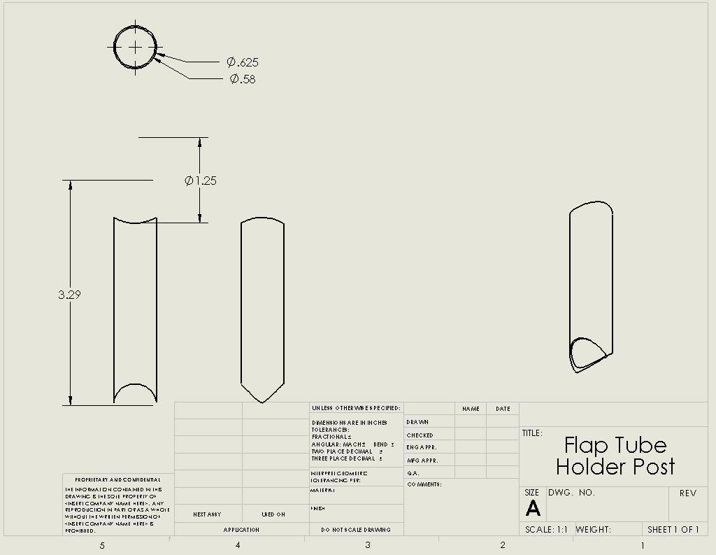
16 16 Appendices Detailed Budget Total Source Use Steel Tube (4130).3125" x.035" x 18" $3.15 Dillsburg Aeroplane Works Rudder cable guides 1.25" x.058" x 6" $1.55 Dillsburg Aeroplane Works Flap tube mounts 1.125" x.035" x 48" $10.40 Dillsburg Aeroplane Works Flap tube, Upper aileron mounts.875" x.058" x 6" $1.35 Dillsburg Aeroplane Works Bolt on control horns.75" x.035" x 78" $13.00 Dillsburg Aeroplane Works Aileron tubes 1" x.035" x 60" $11.50 Dillsburg Aeroplane Works Cross tube, Sticks.375" x.058" x 12" $2.80 Aircraft Spruce Bolt guides.625" x 11" $7.58 Dillsburg Aeroplane Works Axle.625" x.058" x 60" $0.00 Messiah College Flying Club Control system mounting Steel Plate (4130).125" x 2" x 24" $9.20 Dillsburg Aeroplane Works Control horns.125" x 4" x 18" $11.25 Dillsburg Aeroplane Works Control horns, Stick boxes.190 x 4" x 6" $6.52 Dillsburg Aeroplane Works Brake plate mounting Aluminum Tube/ Rod (6061T6).625" x.058" x 78" $12.35 Dillsburg Aeroplane Works Control system pushrods.5" x 66" (solid) $5.50 Dillsburg Aeroplane Works Control system pushrods Hardware.1875" Rod Ends (4) $15.80 Dillsburg Aeroplane Works Control system.25" Rod Ends (10) $35.00 Dillsburg Aeroplane Works Control system Assorted Bolts and Nuts (Temporary) $29.15 Lowes, Home Depot Control system Brakes Shoes - Azusa 5" (pair) $53.92 Appcokarting.com Brake system Drum - Azusa 5" (pair) $18.76 Appcokarting.com Brake system Shipping $9.78 Appcokarting.com Cables (3) $8.97 World Cup Ski and Cycle Brake system 12ft Housing (sleeve) $12.00 World Cup Ski and Cycle Brake system Adjustment Barrels (2) $5.98 World Cup Ski and Cycle Brake system Tax $1.32 World Cup Ski and Cycle $ Total Cost

17 17 Figures Figure 1 Figure 2


18 18 Figure 3 Figure 4


19 19 # Figure 5 Figure 6 Figure 7
20 20 Figure 8 Figure 9

21 21 Figure 10 Figure 11
22 ID Task Name Start Actual Finish Deadline 1 Proj. proposal Sun 9/16/07 Sun 9/30/07 Mon 10/1/07 2 EDR Mon 10/29/07 Mon 12/10/07 Mon 12/10/07 3 EDR draft Mon 11/5/07 Mon 11/12/07 Mon 11/12/07 4 FDR Tue 3/25/08 Thu 5/8/08 Fri 5/9/08 5 Project specifications Wed 10/3/07 Mon 10/29/07 Mon 10/29/07 6 Oral presentation - fall Mon 11/19/07 Mon 12/10/07 Mon 12/10/07 7 Oral presentation - spring Wed 4/30/08 Thu 5/1/08 Fri 5/2/08 8 Prototype construction Tue 9/18/07 Mon 2/4/08 Fri 1/18/08 9 Update mockup Tue 9/18/07 Mon 12/17/07 Mon 10/8/07 10 Folding wings Thu 9/27/07 Tue 1/15/08 Mon 12/10/07 11 Stick ctrls/mixer syst. Thu 9/27/07 Mon 2/4/08 Fri 1/18/08 12 Design Thu 9/27/07 NA Mon 12/10/07 13 Control Systems Thu 9/27/07 NA Mon 12/10/07 14 Mixer Thu 9/27/07 Mon 4/7/08 Mon 12/10/07 15 Elevators Thu 9/27/07 Tue 4/1/08 Mon 12/10/07 16 Rudder Thu 9/27/07 NA Mon 12/10/07 17 Ctrl stick Thu 9/27/07 Fri 4/11/08 Mon 12/10/07 18 Landing gear Wed 10/3/07 Mon 4/7/08 Mon 12/10/07 19 Structure Wed 10/3/07 Wed 10/24/07 Wed 10/24/07 20 Brakes Wed 10/3/07 Mon 4/7/08 Mon 12/10/07 21 Folding Wings Thu 9/27/07 NA Mon 12/10/07 22 MEB Schol. Day presentation Fri 4/18/08 Thu 5/1/08 Fri 5/2/08 23 Order Parts Mon 12/3/07 NA Tue 12/18/07 24 Control Parts Mon 12/3/07 Thu 3/27/08 Tue 12/18/07 25 Landing gear parts Mon 12/3/07 Tue 3/25/08 Tue 12/18/07 26 Folding wing parts Mon 12/3/07 NA Tue 12/18/07 27 Construction Fri 1/11/08 NA Thu 3/13/08 28 Rudder control Mon 2/18/08 NA Thu 3/13/08 29 Elevator control Mon 2/18/08 Thu 5/1/08 Thu 3/13/08 30 Flaperon / mixer control Mon 2/18/08 Wed 4/30/08 Thu 3/13/08 31 Wing folding mechanism Fri 1/11/08 NA Thu 3/13/08 32 Brakes Fri 2/15/08 Thu 5/1/08 Thu 3/13/08 33 Landing gear Fri 2/15/08 NA Thu 3/13/08 34 Testing Mon 10/15/07 NA Fri 4/18/08 35 Wheel friction Mon 10/15/07 NA Sat 12/1/07 36 Brakes Tue 11/20/07 Fri 5/2/08 Wed 2/20/08 37 Landing gear- Landing force Tue 11/20/07 NA Wed 2/20/08 38 Control functionality Tue 3/25/08 Fri 5/2/08 Fri 4/18/08 39 Wing folding Tue 3/25/08 NA Fri 4/18/08 22 Sep '07 Oct ' Proj. proposal Project specifications Update mockup Folding wings Stick ctrls/mixer syst. Mixer Elevators Rudder Ctrl stick Structure Brakes Folding Wings Wheel friction Ora Landing Project: GanttChart.mpp Date: Thu 5/8/08 Task Split Progress Milestone Summary Project Summary External Tasks External Milestone Deadline Page 1
23 23 Nov '07 Dec '07 Jan '08 Feb '08 Mar '08 Apr '08 May ' EDR EDR draft FDR Oral presentation - fall Oral presentation - spring MEB Schol. Day presentation Control Parts Landing gear parts Folding wing parts Rudder control Elevator control Flaperon / mixer control Wing folding mechanism Brakes Landing gear Brakes ing gear- Landing force Control functionality Wing folding Project: GanttChart.mpp Date: Thu 5/8/08 Task Split Progress Milestone Summary Project Summary External Tasks External Milestone Deadline Page 2

24 24

25 25

26 26

27 27

28 28

29 29

30 30

31 31

32 32

33 33

34 34

35 35

36 36
37 37

38 38

39 39

40 40

41 41
Light Sport Aircraft Control System and Wing-Folding Design. Christopher King David Roncin Nathan Swanger
 Light Sport Aircraft Control System and Wing-Folding Design Christopher King David Roncin Nathan Swanger May 11, 2007 Table of Contents Table of Contents.......................................................
SAE Baja - Drivetrain
 SAE Baja - Drivetrain By Ricardo Inzunza, Brandon Janca, Ryan Worden Team 11A Concept Generation and Selection Document Submitted towards partial fulfillment of the requirements for Mechanical Engineering
FOLDING SHOPPING CART
 1 EDSGN 100: Introduction to Engineering Design Section 10 Team 6 FOLDING SHOPPING CART Submitted by: Kevin Chacha, Ugonna Onyeukwu, Patrick Thornton, Brian Hughes Submitted to: Xinli Wu October 28, 2013
Airframes Instructor Training Manual. Chapter 6 UNDERCARRIAGE
 Learning Objectives Airframes Instructor Training Manual Chapter 6 UNDERCARRIAGE 1. The purpose of this chapter is to discuss in more detail the last of the Four Major Components the Undercarriage (or
Lockheed Martin. Team IDK Seung Soo Lee Ray Hernandez Chunyu PengHarshal Agarkar
 Lockheed Martin Team IDK Seung Soo Lee Ray Hernandez Chunyu PengHarshal Agarkar Abstract Lockheed Martin has developed several different kinds of unmanned aerial vehicles that undergo harsh forces when
SAE Mini BAJA: Suspension and Steering
 SAE Mini BAJA: Suspension and Steering By Zane Cross, Kyle Egan, Nick Garry, Trevor Hochhaus Team 11 Progress Report Submitted towards partial fulfillment of the requirements for Mechanical Engineering
M:2:I Milestone 2 Final Installation and Ground Test
 Iowa State University AerE 294X/AerE 494X Make to Innovate M:2:I Milestone 2 Final Installation and Ground Test Author(s): Angie Burke Christopher McGrory Mitchell Skatter Kathryn Spierings Ryan Story
Remote Control Helicopter. Engineering Analysis Document
 Remote Control Helicopter By Abdul Aldulaimi, Travis Cole, David Cosio, Matt Finch, Jacob Ruechel, Randy Van Dusen Team 04 Engineering Analysis Document Submitted towards partial fulfillment of the requirements
Introduction: Problem statement
 Introduction: Problem statement The goal of this project is to develop a catapult system that can be used to throw a squash ball the farthest distance and to be able to have some degree of accuracy with
Here is the gap seal I used for the flaps, genuine hardware store quality. Note cross sectional shape visible on the right end.
 HOMEBUILT AIRCRAFT DRAG REDUCTION - Case Study with a Lancair IV Part 3 Copyright - Fred Moreno - January 2009 Rev. 1 Portions may be reproduced for private, individual use 3- REDUCED AIRFRAME DRAG FOR
Reducing Landing Distance
 Reducing Landing Distance I've been wondering about thrust reversers, how many kinds are there and which are the most effective? I am having a debate as to whether airplane engines reverse, or does something
PAC 750XL PAC 750XL PAC-750XL
 PAC 750XL The PAC 750XL combines a short take off and landing performance with a large load carrying capability. The PAC 750XL is a distinctive type. Its design philosophy is reflected in the aircraft's
FUSELAGE ASSEMBLY SECOND SECTION (of three)
") FUSELAGE ASSEMBLY SECOND SECTION (of three) 1 FRONT FLOOR ASSEMBLY The front floor assembly is fabricated from three pieces of the two ply pre-pregnated panel material supplied. The basic floor panel and
FUSELAGE ASSEMBLY SECOND SECTION (of three) 1 FRONT FLOOR ASSEMBLY The front floor assembly is fabricated from three pieces of the two ply pre-pregnated panel material supplied. The basic floor panel and
Preliminary Detailed Design Review
 Preliminary Detailed Design Review Project Review Project Status Timekeeping and Setback Management Manufacturing techniques Drawing formats Design Features Phase Objectives Task Assignment Justification
Saberwing Aircraft Kit
 Saberwing Aircraft Kit By Azalea Aviation, LLC. Kit Information THE PURPOSE behind the DESIGN The SABERWING is a new aircraft designed and purpose built as an answer to many problems and challenges that
Aircraft Maintenance Prof. A.K Ghosh Prof. Vipul Mathur Department of Aerospace Engineering Indian Institute of Technology, Kanpur
 Aircraft Maintenance Prof. A.K Ghosh Prof. Vipul Mathur Department of Aerospace Engineering Indian Institute of Technology, Kanpur Lecture 05 Aircraft Landing Gear System Now, coming to the next aircraft
2.11 Other Equipment and Installations
 2.10 Tow Releases The tow release fitted at the C. G. is model TOST "Europa G 88" (Data Sheet No: 60.230/2). Models TOST "Europa G 72 or G 73" may be used as a replacement tow release. The forward tow
HYDRAULIC ACTUATOR REPLACEMENT USING ELECTROMECHANICAL TECHNOLOGY
 HYDRAULIC ACTUATOR REPLACEMENT USING ELECTROMECHANICAL TECHNOLOGY SCOPE This white paper discusses several issues encountered by Lee Air with past projects that involved the replacement of Hydraulic Actuators
Progress Report. Maseeh College of Engineering & Computer Science Winter Kart 2. Design Team Atom Falcone Austin Greene. Nick Vanklompenberg
 Progress Report Maseeh College of Engineering & Computer Science Winter 2016 Kart 2 Design Team Atom Falcone Austin Greene Jesse Majoros Nick Vanklompenberg Jake Waterman Jeffrey Williamson Faculty Advisor
TEMPORARY REVISION NUMBER
 TEMPORARY REVISION NUMBER 7 DATED 1 DECEMBER 2011 MANUAL TITLE MANUAL NUMBER - PAPER COPY TEMPORARY REVISION NUMBER Model 188 & T188 Series 1966 Thru 1984 Service Manual D2054-1-13 D2054-1TR7 MANUAL DATE
The following slideshow and talk were presented at the Uber Elevate Summit on April 25 th, The text included here is an approximate transcript
 The following slideshow and talk were presented at the Uber Elevate Summit on April 25 th, 2017. The text included here is an approximate transcript of the speech given by Jay Carter, founder and CEO of
SAE Mini BAJA: Suspension and Steering
 SAE Mini BAJA: Suspension and Steering By Zane Cross, Kyle Egan, Nick Garry, Trevor Hochhaus Team 11 Project Progress Submitted towards partial fulfillment of the requirements for Mechanical Engineering
Linear Induction Motor (LIMO) Modular Test Bed for Various Applications
 Modular Test Bed for Various Applications") Linear Induction Motor (LIMO) Modular Test Bed for Various Applications ECE 4901 Senior Design I Fall 2013 Fall Project Report Team 190 Members: David Hackney Jonathan Rarey Julio Yela Faculty Advisor
Linear Induction Motor (LIMO) Modular Test Bed for Various Applications ECE 4901 Senior Design I Fall 2013 Fall Project Report Team 190 Members: David Hackney Jonathan Rarey Julio Yela Faculty Advisor
TEMPORARY REVISION NUMBER
 TEMPORARY REVISION NUMBER 8 DATED 1 DECEMBER 2011 MANUAL TITLE MANUAL NUMBER - PAPER COPY TEMPORARY REVISION NUMBER 1978 Thru 1986 Model R182 & TR182 Service Manual D2069-3-13 D2069-3TR8 MANUAL DATE 15
ASME Human Powered Vehicle
 ASME Human Powered Vehicle By Yousef Alanzi, Evan Bunce, Cody Chenoweth, Haley Flenner, Brent Ives, and Connor Newcomer Team 14 Mid-Point Review Document Submitted towards partial fulfillment of the requirements
Design, Build, Fly Q&A #1
 2018-19 Design, Build, Fly Q&A #1 Fuselage 1. How do you define a fuselage? How is underneath or bottom of the fuselage defined? Answer: The fuselage is defined as the main body of the airplane that is
A SOLAR POWERED UAV. 1 Introduction. 2 Requirements specification
 A SOLAR POWERED UAV Students: R. al Amrani, R.T.J.P.A. Cloosen, R.A.J.M. van den Eijnde, D. Jong, A.W.S. Kaas, B.T.A. Klaver, M. Klein Heerenbrink, L. van Midden, P.P. Vet, C.J. Voesenek Project tutor:
ASK 21 - Flight Manual. Check List / 1
 Check List / 1 Pre Flight Check 1. Main pins secured? 2. Rear wing attachment pins: is the safety lock visible above the pin? 3. Horizontal tail unit pins secured. Is the spring retainer engaged? 4. Elevator
Table of Contents. Executive Summary...4. Introduction Integrated System...6. Mobile Platform...7. Actuation...8. Sensors...9. Behaviors...
 TaleGator Nyal Jennings 4/22/13 University of Florida Email: Magicman01@ufl.edu TAs: Ryan Chilton Josh Weaver Instructors: Dr. A. Antonio Arroyo Dr. Eric M. Schwartz Table of Contents Abstract...3 Executive
Instruction Manual. Specifications are subjected to change without notice due to product continuous improvements.
 Instruction Manual Specifications are subjected to change without notice due to product continuous improvements. 1 The Wargo Signature Yak 55 is the realization of my goal to have the perfect 3D and aerobatic
A Cost Benefit Analysis of Faster Transmission System Protection Schemes and Ground Grid Design
 A Cost Benefit Analysis of Faster Transmission System Protection Schemes and Ground Grid Design Presented at the 2018 Transmission and Substation Design and Operation Symposium Revision presented at the
AIRCRAFT LANDING GEAR CONSTRUCTION MANUAL
 APPENDIX AI KITPLANES FOR AFRICA AIRCRAFT LANDING GEAR CONSTRUCTION MANUAL Revision: C September 2008 Page L1 of 20 NOTE: Please read the General Manual before proceeding. Please read through the entire
Design Considerations for Stability: Civil Aircraft
 Design Considerations for Stability: Civil Aircraft From the discussion on aircraft behavior in a small disturbance, it is clear that both aircraft geometry and mass distribution are important in the design
Applications in Design & Engine. Analyzing Compound, Robotic Machines
 v2.1 Compound Machines ering Applications in Design & Engine Analyzing Compound, Robotic Machines Educational Objectives At the conclusion of this lesson, students should be able to: Understand the relationship
GlaStar / Sportsman Service Bulletin 64- MANDATORY
 GlaStar / MANDATORY Note: Subject: Applicability: This service bulletin supersedes 49. The service bulletin applicability was updated to include kits. No other changes were made Inspection of welded cage
EDSGN 100: INTRODUCTION TO ENGINEERING DESIGN Section 204 Team #1 BOX CART
 EDSGN 100: INTRODUCTION TO ENGINEERING DESIGN Section 204 Team #1 BOX CART Submitted by: Chang - http://www.personal.psu.edu/cbl5289/ Vinay Murthy - http://www.personal.psu.edu/vum119/ Aidan Fitzpatrick
9 Locomotive Compensation
 Part 3 Section 9 Locomotive Compensation August 2008 9 Locomotive Compensation Introduction Traditionally, model locomotives have been built with a rigid chassis. Some builders looking for more realism
Project Narrative Description
 0 Project Narrative Description Charge Spot is intended to demonstrate the feasibility of an autonomous electric vehicle charging system for residential use. The goal of Charge Spot is to have no user
TEMPORARY REVISION NUMBER
 TEMPORARY REVISION NUMBER 7 DATED 1 DECEMBER 2011 MANUAL TITLE MANUAL NUMBER - PAPER COPY TEMPORARY REVISION NUMBER FR172 Reims Rocket 1968 Thru 1976 Service Manual D849-5-13 D849-5TR7 MANUAL DATE 15 August
(Glider) ASSEMBLY MANUAL
 ASSEMBLY MANUAL") (Glider) MS:132 ASSEMBLY MANUAL Graphics and specifications may change without notice. Specifications: Wing span ------------------------------118.1in (300cm). Wing area ---------------------902.1sq.in
(Glider) MS:132 ASSEMBLY MANUAL Graphics and specifications may change without notice. Specifications: Wing span ------------------------------118.1in (300cm). Wing area ---------------------902.1sq.in
Service Bulletin. ATA 27-00: Flight Controls Rudder-Aileron Interconnect Modification
 Service Bulletin Issued: 09 May 2007 Models SR20 and SR22 ATA 27-00: Flight Controls Rudder-Aileron Interconnect Modification COMPLIANCE Mandatory: Accomplish this Service Bulletin within 25 Flight Hours
The Deployable Gage Restraint Measurement System - Description and Operational Performance
 The Deployable Gage Restraint Measurement System - Description and Operational Performance GARY A. MARTIN ENSCO, INC 5400 PORT ROYAL ROAD SPRINGFIELD, VA 22151 703-321-4513 703-321-7619 (FAX) JEFFREY A.
NEW DESIGN AND DEVELELOPMENT OF ESKIG MOTORCYCLE
 NEW DESIGN AND DEVELELOPMENT OF ESKIG MOTORCYCLE Eskinder Girma PG Student Department of Automobile Engineering, M.I.T Campus, Anna University, Chennai-44, India. Email: eskindergrm@gmail.com Mobile no:7299391869
FIRST FLYING TECHNIQUES COCKPIT PREPARATION STARTUP TAXI
 1. Introduction FIRST FLYING TECHNIQUES COCKPIT PREPARATION STARTUP TAXI We aim to teach and demonstrate how to operate a general aviation aircraft and show some basic techniques and manoeuvres that every
JIM BEDE ADDS TWO HOMEBUILTS TO HIS LINE - THE BD-5J AND THE ALL NEW BD-6
 Newest homebuilt from Jim Bede is the BD-6, a single-place version of the popular four-place BD-4. A BD-6 FOR $2000 JIM BEDE ADDS TWO HOMEBUILTS TO HIS LINE - THE BD-5J AND THE ALL NEW BD-6 By WALTER SHELBOURNE
Solar Boat Capstone Group
 Solar Boat Capstone Group Design Team Chris Maccia, Jeff Tyler, Matt Knight, Carla Pettit, Dan Sheridan Design Advisor Prof. M. Taslim Abstract Every year Solar Splash, the IEEE World Championship of intercollegiate
Stationary Bike Generator System
 Central Washington University ScholarWorks@CWU All Undergraduate Projects Undergraduate Student Projects Spring 2017 Stationary Bike Generator System Rakan Alghamdi Central Washington University, rk_rk11@hotmail.com
Revisiting the Calculations of the Aerodynamic Lift Generated over the Fuselage of the Lockheed Constellation
 Eleventh LACCEI Latin American and Caribbean Conference for Engineering and Technology (LACCEI 2013) International Competition of Student Posters and Paper, August 14-16, 2013 Cancun, Mexico. Revisiting
How to: Test & Evaluate Motors in Your Application
 How to: Test & Evaluate Motors in Your Application Table of Contents 1 INTRODUCTION... 1 2 UNDERSTANDING THE APPLICATION INPUT... 1 2.1 Input Power... 2 2.2 Load & Speed... 3 2.2.1 Starting Torque... 3
Cost Benefit Analysis of Faster Transmission System Protection Systems
 Cost Benefit Analysis of Faster Transmission System Protection Systems Presented at the 71st Annual Conference for Protective Engineers Brian Ehsani, Black & Veatch Jason Hulme, Black & Veatch Abstract
Project Report Cover Page
 New York State Pollution Prevention Institute R&D Program 2015-2016 Student Competition Project Report Cover Page University/College Name Team Name Team Member Names SUNY Buffalo UB-Engineers for a Sustainable
All Credit to Jeff Goin and Scout Paramotoring
 TechDummy Understanding Paramotor Torque & Twist ad how to correct or minimize Mar 18, 2013 Section IV Theory & Understanding See other PPG Bible Additions See also Paramotor Torque Twist and Crash Torque
Introduction. Fuselage/Cockpit
 Introduction The Moravan Zlin 242L is a fully aerobatic 2 seat aircraft designed to perform all advanced flight maneuvers within an envelope of -3.5 to +6 Gs. Many military and civilian flight-training
v1: Mouth Kinematic Design: Double 4-bar Mechanism
 I. Jaw Mechanism Design Overview v1: Mouth Kinematic Design: Double 4-bar Mechanism v2: Mouth Kinematic Design: Single 4-bar Mechanism v2: Overall Design Assembly Issues: Jaw Mechanism Changing from Dinosaur
Mod 71 Nose gear leg bungee, replacement with springs
 Mod 71 Nose gear leg bungee, replacement with springs Classification Optional Applicability Compliance Europa Tri-gear Classic and XS Optional Introduction The steel tube of the Europa s nose gear leg
Design And Development Of Roll Cage For An All-Terrain Vehicle
 Design And Development Of Roll Cage For An All-Terrain Vehicle Khelan Chaudhari, Amogh Joshi, Ranjit Kunte, Kushal Nair E-mail : khelanchoudhary@gmail.com, amogh_4291@yahoo.co.in,ranjitkunte@gmail.com,krockon007@gmail.com
External Hard Drive: A DFMA Redesign
 University of New Mexico External Hard Drive: A DFMA Redesign ME586: Design for Manufacturability Solomon Ezeiruaku 4-23-2013 1 EXECUTIVE SUMMARY The following document serves to illustrate the effects
CHAPTER 11 FLIGHT CONTROLS
 CHAPTER 11 FLIGHT CONTROLS CONTENTS INTRODUCTION -------------------------------------------------------------------------------------------- 3 GENERAL ---------------------------------------------------------------------------------------------------------------------------
The distinguishing features of the ServoRam and its performance advantages
 ADVANCED MOTION TECHNOLOGIES INC 1 The distinguishing features of the ServoRam and its performance advantages What is a Linear Motor? There are many suppliers of electrical machines that produce a linear
Utah Soaring Association Rigging and De-Rigging. USA G-103 Twin II. Procedures for safe assembly and dis-assembly of the glider. (Trailers 1, 2 and 3)
") USA G-103 Procedures for safe assembly and dis-assembly of the glider (Trailers 1, 2 and 3) Grob Glider Rigging Tools Required: Large blade standard screwdriver #2 (medium blade) Phillips screwdriver (if
USA G-103 Procedures for safe assembly and dis-assembly of the glider (Trailers 1, 2 and 3) Grob Glider Rigging Tools Required: Large blade standard screwdriver #2 (medium blade) Phillips screwdriver (if
City of Palo Alto (ID # 6416) City Council Staff Report
 City Council Staff Report") City of Palo Alto (ID # 6416) City Council Staff Report Report Type: Informational Report Meeting Date: 1/25/2016 Summary Title: Update on Second Transmission Line Title: Update on Progress Towards Building
City of Palo Alto (ID # 6416) City Council Staff Report Report Type: Informational Report Meeting Date: 1/25/2016 Summary Title: Update on Second Transmission Line Title: Update on Progress Towards Building
University of New Hampshire: FSAE ECE Progress Report
 University of New Hampshire: FSAE ECE Progress Report Team Members: Christopher P. Loo & Joshua L. Moran Faculty Advisor: Francis C. Hludik, Jr., M.S. Courses Involved: ECE 541, ECE 543, ECE 562, ECE 633,
1.1 REMOTELY PILOTED AIRCRAFTS
 CHAPTER 1 1.1 REMOTELY PILOTED AIRCRAFTS Remotely Piloted aircrafts or RC Aircrafts are small model radiocontrolled airplanes that fly using electric motor, gas powered IC engines or small model jet engines.
36-01 REV 1: Updated figure to depict current F Bellcrank configuration.
 REVISION DESCRIPTION: 36-01 REV 1: Updated figure to depict current F-00067 Bellcrank configuration. 36-06 REV 1: Updated Figure 1 and Figure 2 to depict current F-00067 Bellcrank configuration. 36-07
PilotRC Trainer USER MANUAL
 PilotRC Trainer USER MANUAL Introduction Thank you for purchasing our Trainer plane. we strive to achieve a good quality quick build ARF aircraft. It requires the least amount of assembly of any ARF kit
A Recommended Approach to Pipe Stress Analysis to Avoid Compressor Piping Integrity Risk
 A Recommended Approach to Pipe Stress Analysis to Avoid Compressor Piping Integrity Risk by: Kelly Eberle, P.Eng. Beta Machinery Analysis Calgary, AB Canada keberle@betamachinery.com keywords: reciprocating
XIV.C. Flight Principles Engine Inoperative
 XIV.C. Flight Principles Engine Inoperative References: FAA-H-8083-3; POH/AFM Objectives The student should develop knowledge of the elements related to single engine operation. Key Elements Elements Schedule
Cable Car. Category: Physics: Balance & Center of Mass, Electricity and Magnetism, Force and Motion. Type: Make & Take.
 Cable Car Category: Physics: Balance & Center of Mass, Electricity and Magnetism, Force and Motion Type: Make & Take Rough Parts List: 1 Paperclip, large 2 Paperclips, small 1 Wood stick, 1 x 2 x 6 4 Electrical
Delivery System for Hernia Mesh Fixation
 Delivery System for Hernia Mesh Fixation Design Team Joseph Aaron, Andrew Edgerly Charles O Connell, Charles Sidoti, David Stone Design Advisor Dr. Jeffrey Ruberti Sponsor High Road Medical Abstract The
USA G-103 Twin Astir
 USA G-103 Procedures for safe assembly and dis-assembly of the glider (Trailers 2 and 3) Grob Glider Rigging Tools Required: Needle nosed pliers Wire cutters (side cut) Very large crescent wrench (for
Stationary Bike Generator System (Drive Train)
") Central Washington University ScholarWorks@CWU All Undergraduate Projects Undergraduate Student Projects Summer 2017 Stationary Bike Generator System (Drive Train) Abdullah Adel Alsuhaim cwu, 280zxf150@gmail.com
Central Washington University ScholarWorks@CWU All Undergraduate Projects Undergraduate Student Projects Summer 2017 Stationary Bike Generator System (Drive Train) Abdullah Adel Alsuhaim cwu, 280zxf150@gmail.com
United States Patent (19) Cronk et al.
 Cronk et al.") United States Patent (19) Cronk et al. (S4) LANDING GEAR FOR ULTRALIGHT AIRCRAFT 76) Inventors: David Cronk, 1069 Eucalyptus Ave., Vista, Calif. 92025; Lyle M. Byrum, 1471 Calle Redonda, Escondido, Calif.
United States Patent (19) Cronk et al. (S4) LANDING GEAR FOR ULTRALIGHT AIRCRAFT 76) Inventors: David Cronk, 1069 Eucalyptus Ave., Vista, Calif. 92025; Lyle M. Byrum, 1471 Calle Redonda, Escondido, Calif.
Supervised Learning to Predict Human Driver Merging Behavior
 Supervised Learning to Predict Human Driver Merging Behavior Derek Phillips, Alexander Lin {djp42, alin719}@stanford.edu June 7, 2016 Abstract This paper uses the supervised learning techniques of linear
AIRCRAFT DESIGN MADE EASY. Basic Choices and Weights. By Chris Heintz
 AIRCRAFT DESIGN MADE EASY By Chris Heintz The following article, which is a first installement of a two-part article, describes a simple method for the preliminary design of an airplane of conventional
It has taken a while to get
 HOVERING15 99 15 BASICS HOVERING Hovering It has taken a while to get here, but this is what all the building and planning were for to see light under those skids. But this is also the time when you have
Sierra. R/STOL High Lift Systems. Toll Free LANCAIR. Sierra R/STOL High Lift System Benefits DURING APPROACH AND LANDING DURING TAKEOFF
 Sierra R/STOL High Lift Systems Complete R/STOL Systems include everything your aircraft needs for the utmost in performance. For expanded utility, increased safety and improved performance get off the
4.1 General Information. 4.2 Turning Radii. 4.3 Clearance Radii. 4.4 Visibility From Cockpit in Static Position. 4.5 Runway and Taxiway Turn Paths
 4.0 GROUND MANEUVERING 4.1 General Information 4.2 Turning Radii 4.3 Clearance Radii 4.4 Visibility From Cockpit in Static Position 4.5 Runway and Taxiway Turn Paths 4.6 Runway Holding Bay DECEMBER 2002
PRESEASON CHASSIS SETUP TIPS
 PRESEASON CHASSIS SETUP TIPS A Setup To-Do List to Get You Started By Bob Bolles, Circle Track Magazine When we recently set up our Project Modified for our first race, we followed a simple list of to-do
RIGGING THE FLIGHT CONTROLS
 RIGGING THE FLIGHT CONTROLS Rigging refers to the installation and adjustment of the rods that move flight surfaces in response to inputs from the controls of the helicopter. These rods are cut to length,
Problem Statement. After losing hydraulic systems when engine #1 detached during takeoff.
 Problem Statement Report umber RCA-28-07-17-114 RCA Owner Chris Eckert Report Date 7/28/2017 RCA Facilitator Brian Hughes Focal Point: Crashed - 273 Fatalities When Start Date: 5/25/1979 End Date: 5/25/1979
Assemblies for Parallel Kinematics. Frank Dürschmied. INA reprint from Werkstatt und Betrieb Vol. No. 5, May 1999 Carl Hanser Verlag, München
 Assemblies for Parallel Kinematics Frank Dürschmied INA reprint from Werkstatt und Betrieb Vol. No. 5, May 1999 Carl Hanser Verlag, München Assemblies for Parallel Kinematics Frank Dürschmied Joints and
High aspect ratio for high endurance. Mechanical simplicity. Low empty weight. STOVL or STOL capability. And for the propulsion system:
 Idealized tilt-thrust (U) All of the UAV options that we've been able to analyze suffer from some deficiency. A diesel, fixed-wing UAV could possibly satisfy the range and endurance objectives, but integration
LOAD CELL USE IN AEROSPACE GROUND AND FLIGHT TEST APPLICATIONS A Honeywell White Paper
 LOAD CELL USE IN AEROSPACE GROUND AND FLIGHT TEST APPLICATIONS A Honeywell White Paper Load Cell Use in Aerospace Ground & Flight Test Applications White Paper sensing.honeywell.com 2 Abstract A load cell
Building A Replica Aircraft. Part Two Construction Details Fuselage and Tail Group
 Building A Replica Aircraft Part Two Construction Details Fuselage and Tail Group Brief Review After obtaining a partially complete Graham Lee 7/8 scale Nieuport 11 project I decided to reconfigure it
52 BACKYARDFLYER.COM FLY
 52 BACKYARDFLYER.COM FLY HELIS IN1O EASY STEPS by Klaus Ronge Photography by Hope McCall & Pete Hall Flying model helicopters is exciting and fun and looks very easy, that is, until you try it. Unlike
NASA centers team up to tackle sonic boom 18 March 2014, by Frank Jennings, Jr.
 NASA centers team up to tackle sonic boom 18 March 2014, by Frank Jennings, Jr. This rendering shows the Lockheed Martin future supersonic advanced concept featuring two engines under the wings and one
Development of a Rubber Disc Piston Seal for the Mahadaga Handpump Peter Govey, Christopher Claassen, Joseph Longenecker Messiah College 2006
 Development of a Rubber Disc Piston Seal for the Mahadaga Handpump Peter Govey, Christopher Claassen, Joseph Longenecker Messiah College 2006 Abstract We developed a new concept for a piston seal that
SAE Aero Design. Mid point Review. Ali Alqalaf, Jasem Alshammari, Dong Yang Cao, Darren Frankenberger, Steven Goettl, and John Santoro Team 16
 SAE Aero Design Mid point Review Ali Alqalaf, Jasem Alshammari, Dong Yang Cao, Darren Frankenberger, Steven Goettl, and John Santoro Team 16 Submitted towards partial fulfillment of the requirements for
AVIATION INVESTIGATION REPORT A01Q0009 LOSS OF CONTROL ON TAKE-OFF
 AVIATION INVESTIGATION REPORT A01Q0009 LOSS OF CONTROL ON TAKE-OFF PA-28-140 C-FXAY MASCOUCHE, QUEBEC 13 JANUARY 2001 The Transportation Safety Board of Canada (TSB) investigated this occurrence for the
Electronic Shifter. Lee Redstone V Lewis Weston V Jason Deglint V Group #5. Supervisor Ashoka K. S. Bhat. Due Oct.
 Electronic Shifter Lee Redstone V00662175 Lewis Weston V00766616 Jason Deglint V00730963 Group #5 Supervisor Ashoka K. S. Bhat Due Oct. 16, 2012 Dept. Electrical and Computer Engineering University of
Cane Creek Double Barrel Instructions
 Cane Creek Double Barrel Instructions Congratulations on your purchase of the Cane Creek Double Barrel rear shock. Developed in partnership with Öhlins Racing, the Double Barrel brings revolutionary suspension
GNEG 1103 Introduction to Engineering FALL Team Design Project. Portable Phone Charger. Project Presentation. December 2, 2013, 8:00-9:15 A.
 1 GNEG 1103 Introduction to Engineering FALL 2013 Team Design Project Portable Phone Charger Project Presentation December 2, 2013, 8:00-9:15 A.M Derek Richard, Jarod Brunick, Luis Ramirez, Mason Torgerson
Theory of Flight. Main Teaching Points. Definition Parts of an Airplane Aircraft Construction Landing Gear Standard Terminology
 Theory of Flight 6.01 Aircraft Design and Construction References: FTGU pages 9-14, 27 Main Teaching Points Parts of an Airplane Aircraft Construction Standard Terminology Definition The airplane is defined
Stomp Rockets. Flight aboard the USS Hornet. From the USS Hornet Museum Education Department. Sue Renner and Alissa Doyle (rev.
 Stomp Rockets Flight aboard the USS Hornet From the USS Hornet Museum Education Department Sue Renner and Alissa Doyle (rev. May 2018) Alissa.Doyle@uss-hornet.org USS Hornet Museum Education Department
Orbital Test Stand. By Mary Begay, Brett Booen, Calvin Boothe, James Ellis and Nicholas Garcia. Team 7. Project Proposal Document
 Orbital Test Stand By Mary Begay, Brett Booen, Calvin Boothe, James Ellis and Nicholas Garcia Team 7 Project Proposal Document Submitted towards partial fulfillment of the requirements for Mechanical Engineering
Pilatus B-4 Procedures for safe assembly and dis-assembly of the glider
 Pilatus B-4 Procedures for safe assembly and dis-assembly of the glider (Trailer 6) Pilatus B-4 Procedures for safely removing the various components from the trailer, and for assembly of the glider Initial
13.3 List of Maintenance Documents for fitted Equipment
 Maintenance Manual Maintenance Manual 13.3 List of Maintenance Documents for fitted Equipment - Engine Manual for the power-plant IAE 50R-AA in its currently valid edition. - Operating and Maintenance
7. PRELIMINARY DESIGN OF A SINGLE AISLE MEDIUM RANGE AIRCRAFT
 7. PRELIMINARY DESIGN OF A SINGLE AISLE MEDIUM RANGE AIRCRAFT Students: R.M. Bosma, T. Desmet, I.D. Dountchev, S. Halim, M. Janssen, A.G. Nammensma, M.F.A.L.M. Rommens, P.J.W. Saat, G. van der Wolf Project
International Journal of Scientific & Engineering Research, Volume 4, Issue 7, July ISSN BY B.MADHAN KUMAR
 International Journal of Scientific & Engineering Research, Volume 4, Issue 7, July-2013 485 FLYING HOVER BIKE, A SMALL AERIAL VEHICLE FOR COMMERCIAL OR. SURVEYING PURPOSES BY B.MADHAN KUMAR Department
2 nd Generation Charging Station
 2 nd Generation Charging Station By Jasem Alhabashy, Riyadh Alzahrani, Brandon Gabrelcik, Ryan Murphy and Ruben Villezcas Team 13 Progress Report for ME486c Document Submitted towards partial fulfillment