A Practical Guide to Free Energy Devices
|
|
|
- Alan Floyd
- 6 years ago
- Views:
Transcription

1 A Practical Guide to Free Energy Devices Part 16: Last updated: 28th January 2006 Author: Patrick J. Kelly Please note that this is a re-worded extract from Edwin Gray s Patent 3,890,548. It describes his high voltage motor and the circuitry used to drive it. This motor was shown to have 80 horsepower of excess energy. United States Patent 3,890,548 June 17, 1975 Inventor: Edwin V. Gray snr. PULSED CAPACITOR DISCHARGE ELECTRIC ENGINE
2
3
4
5
6
7
8
9 SUMMARY OF THE INVENTION: This invention relates to electric motors or engines, and more particularly to a new electric machine including electromagnetic poles in a stator configuration and electromagnetic poles in a rotor configuration, wherein in one form thereof, the rotor is rotatable within the stator configuration and where both are energised by capacitor discharges through rotor and stator electromagnets at the instant of the alignment of a rotor electromagnet with a stator electromagnet. The rotor electromagnet is repelled from the stator electromagnet by the discharge of the capacitor through the coils of both the rotor and stator electromagnets at the same instant. In an exemplary rotary engine according to this invention, rotor electromagnets may be disposed 120 degrees apart on a central shaft and major stator electromagnets may be disposed 40 degrees apart in the motor housing about the stator periphery. Other combinations of rotor elements and stator elements may be utilised to increase torque or rate of rotation. In another form, a second electromagnet is positioned to one side of each of the major stator electromagnets on a centreline 13.5 degrees from the centreline of the stator magnet, and these are excited in a predetermined pattern or sequence. Similarly, to one side of each rotor electromagnet, is a second electromagnet spaced on a 13.5 degree centreline from the major rotor electromagnet. Electromagnets in both the rotor and stator assemblies are identical, the individual electromagnets of each being aligned axially and the coils of each being wired so that each rotor electromagnetic pole will have the same magnetic polarity as the electromagnet in the stator with which it is aligned and which it is confronting at the time of discharge of the capacitor. Charging of the discharge capacitor or capacitors is accomplished by an electrical switching circuit wherein electrical energy from a battery or other source of d-c potential is derived through rectification by diodes. The capacitor charging circuit comprises a pair of high frequency switchers which feed respective automotive-type ignition coils employed as step-up transformers. The secondary of each of the ignition coils provides a high voltage square wave to a half-wave rectifier to generate a high voltage output pulse of d-c energy with each switching alternation of the high frequency switcher. Only one polarity is used so that a unidirectional pulse is applied to the capacitor bank being charged. Successive unidirectional pulses are accumulated on the capacitor or capacitor bank until discharged. Discharge of the bank of capacitors occurs across a spark gap by arc-over. The gap spacing determines the voltage at which discharge or arc-over occurs. An array of gaps is created by fixed elements in the engine housing and moving elements positioned on the rotor shaft. At the instant when the moving gap elements are positioned opposite fixed elements during the rotor rotation, a discharge occurs through the coils of the aligned rotor and stator electromagnets to produce the repulsion action between the stator and rotor electromagnet cores. A plurality of fixed gap elements are arrayed in a motor housing to correspond to the locations of the stator electromagnets in the housing. The rotor gap elements correspond to the positions of the rotor electromagnets on the rotor so that at the instant of correct alignment of the gaps, the capacitors are discharged to produce the necessary current through the stator and rotor coils to cause the electromagnets to repel one another. The charging circuits are arranged in pairs, and are such that the discharge occurs through both rotor and stator windings of the electromagnets, which are opposite one another when the spark gap elements are aligned and arc-over.
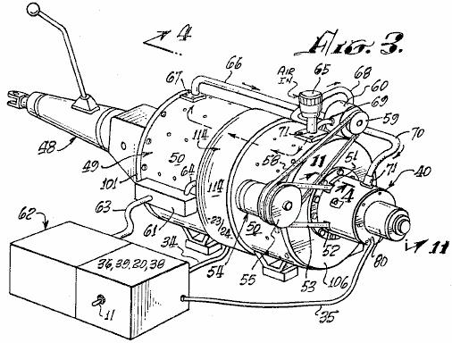
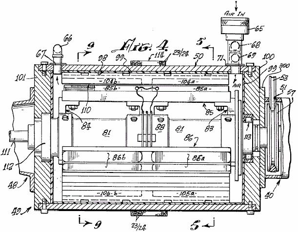
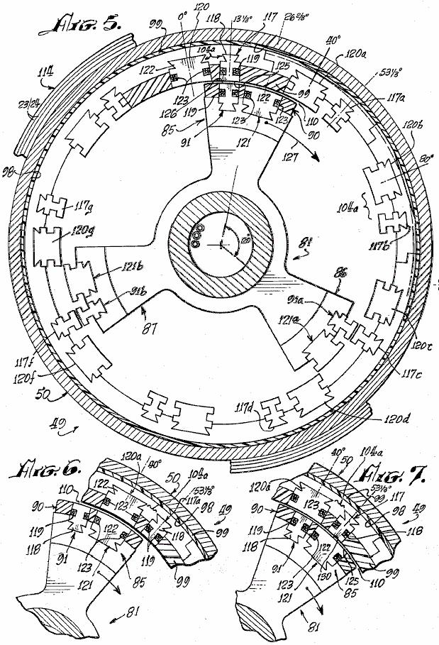
10 The speed of the rotor can be changed by means of a clutch mechanism associated with the rotor. The clutch shifts the position of the rotor gap elements so that the discharge will energise the stator coils in a manner to advance or retard the time of discharge with respect to the normal rotor/stator alignment positions. The discharge through the rotor and stator then occurs when the rotor has passed the stator by 6.66 degrees for speed advance. By causing the discharge to occur when the rotor position is approaching the stator, the repulsion pulse occurs 6.66 degrees before the alignment position of the rotor and stator electromagnets, thus reducing the engine speed. The clutch mechanism for aligning capacitor discharge gaps for discharge is described as a control head. It may be likened to a firing control mechanism in an internal combustion engine in that it fires the electromagnets and provides a return of any discharge overshoot potential back to the battery or other energy source. The action of the control head is extremely fast. From the foregoing description, it can be anticipated that an increase in speed or a decrease in speed of rotation can occur within the period in which the rotor electromagnet moves between any pair of adjacent electromagnets in the stator assembly. These are 40 degrees apart so speed changes can be effected in a maximum of one-ninth of a revolution. The rotor speed-changing action of the control head and its structure are believed to be further novel features of the invention, in that they maintain normal 120 degree firing positions during uniform speed of rotation conditions, but shift to 6.66 degree longer or shorter intervals for speed change by the novel shift mechanism in the rotor clutch assembly. Accordingly, the preferred embodiment of this invention is an electric rotary engine wherein motor torque is developed by discharge of high potential from a bank of capacitors, through stator and rotor electromagnet coils when the electromagnets are in alignment. The capacitors are charged from batteries by a switching mechanism, and are discharged across spark gaps set to achieve the discharge of the capacitor charge voltage through the electromagnet coils when the gaps and predetermined rotor and stator electromagnet pairs are in alignment. Exemplary embodiments of the invention are herein illustrated and described. These exemplary illustrations and description should not be construed as limiting the invention to the embodiments shown, because those skilled in the arts appertaining to the invention may conceive of other embodiments in the light of the description within the ambit of the appended claims. BRIEF DESCRIPTION OF THE DRAWINGS: Fig.1 is an explanatory schematic diagram of a capacitor charging and discharging circuit utilised in the present invention. Fig.2 is a block diagram of an exemplary engine system according to the invention. Fig.3 is a perspective view of a typical engine system according to the invention, coupled to an automotive transmission. Fig.4 is an axial sectional view taken at line in Fig.3 Fig.5 is a sectional view taken at line in Fig.4 Fig.6 and Fig.7 are fragmentary sectional views, corresponding to a portion of Fig.5, illustrating successive advanced positions of the engine rotor therein.
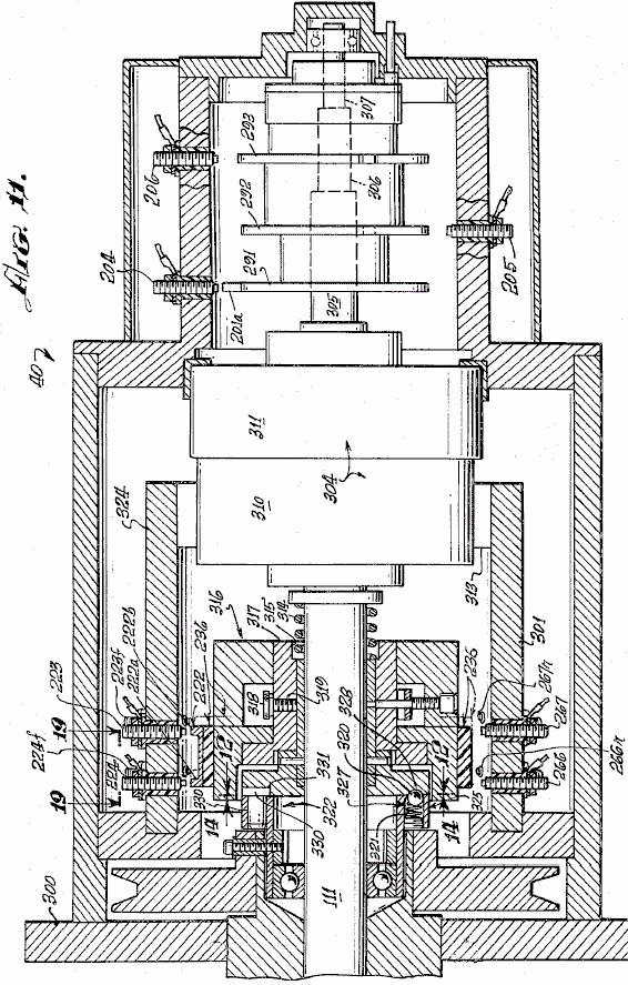
11 Fig.8 is an exploded perspective view of the rotor and stator of the engine of Fig.3 and Fig.4 Fig.9 is a cross-sectional view taken at line of Fig.4 Fig.10 is a partial sectional view, similar to the view of Fig.9, illustrating a different configuration of electromagnets in another engine embodiment of the invention. Fig.11 is a sectional view taken at line in Fig.3, illustrating the control head or novel speed change controlling system of the engine. Fig.12 is a sectional view, taken at line in Fig.11, showing a clutch plate utilised in the speed change control system of Fig.11 Fig.13 is a fragmentary view, taken at line in Fig.12 Fig.14 is a sectional view, taken at line in Fig.11, showing a clutch plate which cooperates with the clutch plate of Fig.12 Fig.15 is a fragmentary sectional view taken at line of Fig.13 Fig.16 is a perspective view of electromagnets utilised in the present invention. Fig.17 is a schematic diagram showing co-operating mechanical and electrical features of the programmer portion of the invention. Fig.18 is an electrical schematic diagram of an engine according to the invention, showing the electrical relationships of the electromagnetic components embodying a new principle of the invention, and Fig.19 is a developed view, taken at line of Fig.11, showing the locations of displaced spark gap elements of the speed changing mechanism of an engine according to the invention. DESCRIPTION OF THE PREFERRED EMBODIMENT: As mentioned earlier, the basic principle of operation of the engine of the invention, is the discharge of a capacitor across a spark gap and through an inductor. When a pair of inductors is used, and the respective magnetic cores thereof are arranged opposite one another and arranged in opposing magnetic polarity, the discharge through them causes the cores to repel each other with considerable force. Referring to the electrical schematic diagram of Fig.1, a battery 10 energises a pulse-producing vibrator mechanism 16, which may be of the magnetic type, incorporating an armature 15 moving between contacts 13 and 14, or of the transistor type (not shown) with which a high frequency bipolar pulsed output is produced in primary 17 of transformer 20. The pulse amplitude is stepped up in secondary 19 of transformer 20. Wave form 19a represents the bi-directional or bipolar pulsed output. A diode rectifier 21 produces a unidirectional pulse train, as indicated at 21a, to charge capacitor 26. Successive unidirectional pulses of wave 21a charge capacitor 26 to high level, as indicated at 26a, until the voltage at point A rises high enough to cause a spark across the spark gap 30. Capacitor 26 discharges via the spark gap, through the electromagnet coil 28. A current pulse is produced which magnetises core 28a. Simultaneously, another substantially identical charging system 32 produces a discharge through inductor 27 across spark gap 29, to magnetise core 27a. Cores 27a and 28a are wound with coils 27 and 28 respectively, so that their magnetic polarities are the same. As the cores 27a and 28a confront one another, they tend to fly apart when the discharge occurs through coils 27 and 28 because of
12 repulsion of identical magnetic poles, as indicated by arrow 31. If core 28a is fixed or stationary, and core 27a is moveable, then core 27a may have tools 33 attached to it to perform work when the capacitor discharges. Referring to Fig.1 and Fig.2, a d-c electrical source or battery 10, energises pulsators 36 (including at least two vibrators 16 as previously described) when switch 11 between the battery 10 and pulsator 36 is closed, to apply relatively high frequency pulses to the primaries of transformers 20. The secondaries of transformers 20 are step-up windings which apply bipolar pulses, such as pulses 19a (Fig.1) to the diodes in converter 38. The rectified unidirectional pulsating output of each of the diodes in converter 38 is passed through delay coils 23 and 24, thus forming a harness 37, wound about the case of the engine, as herein after described, which is believed to provide a static floating flux field. The outputs from delay lines 37, drive respective capacitors in banks 39, to charge the capacitors therein, to a relatively high charge potential. A programmer and rotor and stator magnet control array 40, 41, 42, is formed by spark gaps positioned, as hereinafter described, so that at predetermined positions of the rotor during rotation of the engine, as hereinafter described, selected capacitors of the capacitor banks 39 will discharge across the spark gaps through the rotor and stator electromagnets 43 and 44. The converters 38, programmer 40, and controls 41 and 42, form a series circuit path across the secondaries of transformers 20 to the ground, or point of reference potential, 45. The capacitor banks 39 are discharged across the spark gaps of programmer 40 (the rotor and stator magnet controls 41 and 42). The discharge occurs through the coils of stator and rotor electromagnets 43 and 44 to ground 45. Stator and rotor electromagnets are similar to those shown at 27, 27a, 28 and 28a in Fig.1. The discharge through the coils of stator and rotor electromagnets 43 and 44 is accompanied by a discharge overshoot or return pulse, which is applied to a secondary battery 10a to store this excess energy. The overshoot pulse returns to battery 10a because, after discharge, the only path open to it is that to the battery 10a, since the gaps in 40, 41 and 42 have broken down, because the capacitors in banks 39 are discharged and have not yet recovered the high voltage charge from the high frequency pulsers 36 and the converter rectifier units 38. In the event of a misfire in the programmer control circuits 40, 41 and 42, the capacitors are discharged through a rotor safety discharge circuit 46 and returned to batteries 10-10a, adding to their capacity. The circuit 46 is connected between the capacitor banks 39 and batteries 10, 10a. Referring to Fig.3, a motor or engine 49 according to the present invention is shown connected with an automotive transmission 48. The transmission 48, represents one of many forms of loads to which the engine may be applied. A motor housing 50, encases the operating mechanism hereinafter described. The programmer 40 is axially mounted at one end of the housing. Through apertures 51 and 52, a belt 53 couples to a pulley 57 (not shown in this view) and to an alternator 54 attached to housing 50. A pulley 55 on the alternator, has two grooves, one for belt 53 to the drive pulley 58 on the shaft (not shown) of the engine 49, and the other for a belt 58 coupled to a pulley 59 on a pump 60 attached to housing 50, A terminal box 61 on the housing, interconnects between the battery assembly 62 and motor 49 via cables 63 and 64. An intake 65 for air, is coupled to pump 60 via piping 68 and 69 and from pump 60 via tubing or piping 66 and 70 to the interior of housing 50 via coupling flanges 67 and 71. The air flow tends to cool the engine and the air may preferably be maintained at a constant temperature and humidity so that a constant spark gap discharge condition is maintained. A clutch mechanism 80 is provided on programmer 40. Referring to Fig.4, Fig.5 and Fig.9, rotor 81 has spider assemblies 83 and 84 with three electromagnet coil assembly sets mounted thereon, two of which are shown in Fig.4, on 85, at 85a and 85b and on 86 at 86a and 86b. One of the third electromagnet coil assemblies, designated 87a, is shown in Fig.5, viewed from the shaft end. As more clearly shown in the
13 perspective view of Fig.8, a third spider assembly 88 provides added rigidity and a central support for the rotor mechanism on shaft 81. The electromagnet sets 85a, 85b, 86a, 86b, 87a and 87b, disposed on rotor 81 and spiders 83, 84 and 88, each comprise pairs of front units 85a, 86a and 87a and pairs of rear units 85b, 86b and 87b. Each pair consists of a major electromagnet and a minor electromagnet, as hereinafter described, which are imbedded in an insulating material 90, which insulates the electromagnet coil assemblies from one another and secures the electromagnets rigidly in place on the spider/rotor cage 81, 83, 84 and 88. The interior wall 98, of housing 50, is coated with an electrically insulating material 99 in which are imbedded electromagnet coils, as hereinafter described, and the interiors of end plates 100 and 101 of the housing 50. On the insulating surface 98 of housing 50 is mounted a series of stator electromagnet pairs 104a, identical with electromagnet pairs 85a, 86a, 87a, etc. Electromagnet pairs such as 104a or 105a are disposed every 40 degrees about the interior of housing 50 to form a stator which co-operates with the rotor An air gap 110 of very close tolerance is defined between the rotor and stator electromagnets and air from pump 65 flows through this gap. As shown in Fig.8, the electromagnet assemblies, such as 85 through 87, of the rotor and magnet assemblies, such as 104a in the stator, are so embedded in their respective insulating plastic carriers (rotor and stator) that they are smoothly rounded in a concave contour on the rotor to permit smooth and continuous rotation of rotor 81 in stator housing 50. The air gap 110 is uniform at all positions of any rotor element within the stator assembly, as is clearly shown in Fig.16. The rotor 81 and spiders 83, 84 and 88 are rigidly mounted on shaft 111 journaled in bearing assemblies 112 and 113 which are of conventional type, for easy rotation of the rotor shaft 111 within housing 50. Around the central outer surface of housing 50, are wound a number of turns of wire 23 and 24 to provide a static flux coil 114 which is a delay line, as previously described. Figs. 5, 6, 7 and 9 are cross-sectional views of the rotor assembly 81-88, arranged to show the positioning and alignment of the rotor and stator electromagnet coil assemblies at successive stages of the rotation of the rotor through a portion of a cycle of operation thereof. For example, in Fig.5 the rotor assembly is shown so positioned that a minor rotor electromagnet assembly 91 is aligned with a minor stator electromagnet assembly 117. As shown in further detail in Fig.16, minor electromagnet assembly 117 consists of an iron core 118, grooved so that a coil of wire 119 may be wound around it. Core 118 is the same in stator electromagnet 117 as it is in rotor electromagnet 91. As a position degrees to the right of rotor electromagnet 91, as viewed in Fig.5 and Fig.16, there is a second or major rotor electromagnet 121 which has a winding 123 about its core 122. The electromagnets 91 and 121 are the pair 85a of Fig.4 and Fig.8. At a position degrees to the left of stator electromagnet 117, as viewed in Fig.5, there is a second or major stator electromagnet 120 whose core 122 is of the same configuration as core 122 of rotor electromagnet 121. A winding 123 about core 122 of electromagnet 120 is of the same character as winding 123 on electromagnet 121. Electromagnet assembly pair 85a on the rotor is identical in configuration to that of the electromagnet stator assembly pair 104a except for the position reversal of the elements and of the respective pairs.
14 There are none pairs of electromagnets (104a) located at 40 degree intervals about the interior of housing 50. The centreline of core 122 of electromagnet 120 is positioned degrees to the left of the centreline of the core 118 of electromagnet 117. Three pairs of electromagnets 85a, 86a and 87a are provided on rotor assembly as shown in Fig.5. Other combinations are possible, but the number of electromagnets in the rotor should always be in integral fraction of the number of electromagnets in the stator. As shown in Fig.8, for the rotor assembly 85a and 85b, there are three of each of the front and back pairs of electromagnetic assemblies. Similarly, as shown in Fig.4 and Fig.8, there are nine front and back pairs of electromagnets in the stator such as 104a and 104b. In order to best understand the operation of the rotor rotating within the stator housing 50 of an engine according to this invention, the positions of rotor electromagnets 91 and stator electromagnets 117 are initially exactly in line at the degree peripheral starting position marked on the vertical centreline of Fig.5. The winding direction of the coils of these magnets is such that a d-c current through the coils 119 will produce a particular identical magnet polarity on each of the juxtaposed surfaces 125 of magnet 117 and 126 of magnet 91 (Fig.5). Fig.16 and Fig.6 illustrate the next step in the motion wherein the two major electromagnets, 120 in the stator and 121 in the rotor, are in alignment. When the d-c discharges from the appropriate capacitors in banks 39 occur simultaneously across spark gaps through the coils 119 of electromagnets 117 and 91, at the instant of their alignment, their cores 118, will repel one another to cause rotor assembly to rotate clockwise in the direction indicated by arrow 127. The system does not move in the reverse direction because it has been started in the clockwise direction by the alternator motor 54 shown in Fig.3, or by some other starter means. If started counterclockwise, the motor will continue to rotate counterclockwise. As noted earlier, the discharge of any capacitor occurs over a very short interval via its associated spark gap and the resulting magnetic repulsion action imparts motion to the rotor. The discharge event occurs when electromagnets 117 and 91 are in alignment. As shown in Fig.5, rotor electromagnet 91a is aligned with stator electromagnet 117c, and rotor electromagnet 91b is aligned with stator electromagnet 117e at the same time that similar electromagnets 117 and 91 are aligned. A discharge occurs through all six of these electromagnets simultaneously (that is, 117, 91, 117c, 91a, 117e and 91b). A capacitor and a spark gap are required for each coil of each electromagnet. Where, as in the assembly shown in Fig.8, front and back pairs are used, both the axial in-line front and back coils are energised simultaneously by the discharge from a single capacitor or from a bank of paralleled capacitors such as 25 and 26 (Fig.1). Although Fig.4 and Fig.8 indicate the use of front and back electromagnets, it should be evident that only a single electromagnet in any stator position and a corresponding single electromagnet in the rotor position, may be utilised to accomplish the repulsion action of the rotor with respect to the stator. As stated, each electromagnet requires a discharge from a single capacitor or capacitor bank across a spark gap for it to be energised, and the magnetic polarity of the juxtaposed magnetic core faces must be the same, in order to effect the repulsive action required to produce the rotary motion. Referring to Fig.5 and Fig.6, the repulsion action causes the rotor to move degrees clockwise, while electromagnets 91, 91a and 91b move away from electromagnets 117, 117c and 117e to bring electromagnets 121, 121a and 121b into respective alignment with electromagnets 120a, 120d and 120f. At this time, a capacitor discharge across a spark-gap into their coils 123 occurs, thus moving the rotor. Another degrees ahead, as shown in Fig.7, major electromagnets 121, 121a and 121b come into alignment with minor electromagnets 117a, 117d and 117f, at which time a discharge occurs to repeat the repulsion action, this action continuing as long as d-c power is applied to the system to charge the capacitor banks.
15 Fig.18 further illustrates the sequencing of the capacitor discharges across appropriate spark gap terminal pairs. Nine single stator coils and three single rotor coils are shown with their respective interconnections with the spark gaps and capacitors with which they are associated for discharge. When the appropriate spark gap terminals are aligned, at the points in the positioning of the rotor assembly for most effective repulsion action of juxtaposed electromagnet cores, the discharge of the appropriate charged capacitors across the associated spark gap occurs through the respective coils. The capacitors are discharged is sets of three, through sets of three coils at each discharge position, as the rotor moves through the rotor positions. In Fig.18, the rotor electromagnets are positioned linearly, rather than on a circular base, to show the electrical action of an electric engine according to the invention. These motor electromagnets 201, 202 and 203 are aligned with stator electromagnets 213, 214 and 215 at 0 degrees, 120 degrees and 240 degrees respectively. The stator electromagnets are correspondingly shown in a linear schematic as if rolled out of the stator assembly and laid side by side. For clarity of description, the capacitors associated with the rotor operation 207, 208, 209 and 246, 247, 248, 249, 282 and 283, are arranged in vertical alignment with the respective positions of the rotor coils 201, 202 and 203 as they move from left to right, this corresponding to clockwise rotation of the rotor. The stator coils 213, 214, 215, 260, 261, 262, 263, 264, 265, 266, etc. and capacitor combinations are arranged side by side, again to facilitate description. An insulative disc 236 (shown in Fig.17 as a disc but opened out linearly in Fig.18) has mounted thereon, three gap terminal blocks 222, 225 and 228. Each block is rectangularly U-shaped, and each interconnects two terminals with the base of the U. Block 222 has terminals 222a and 222b. Block 225 has terminals 225a and 225b. Block 228 has terminals 228c and 228d. When insulative disc 230 is part of the rotor as indicated by mechanical linkage 290, it can be seen that terminal U 222 creates a pair of gaps with gap terminals 223 and 224 respectively. Thus, when the voltage on capacitor 216 from charging unit 219, is of a value which will arc over the air spaces between 222a and 223, and between 222b and 224, the capacitor 216 will discharge through the coil of electromagnet 213 to ground. Similarly, gap terminal U 225 forms a dual spark gap with gap terminals 226 and 227 to result in arc-over when the voltage on capacitor 217, charged by charging circuit 220, discharges into the coil of electromagnet 214. Also, U-gap terminal 228 with terminals 228c and 228d, creates a spark gap with terminals 229 and 230 to discharge capacitor 218, charged by charging circuit 221, into coil 215. At the same time, rotor coils, 201, 202 and 203 across gaps 201a - 204, 202b and 203c each receives a discharge from respective capacitors 207, 208 and 209. When the electromagnet coils 213, 214 and 215 and 201, 202 and 203 are energised, the repulsion action causes the rotor assembly to move to position 2 where a new simultaneous group of discharges occurs into rotor coils 201, 202 and 203 from capacitors 246, 248 and 282 across gaps 201a - 240, 202b and 203c Simultaneously, because gap-u-elements 222, 225 and 228 have also moved to position 2 with the rotor assembly, capacitor 261 is discharged through electromagnet coil 260, capacitor 265 is discharged through electromagnet coil 264, and capacitor 269 is discharged through electromagnet coil 268 in alignment with position 2 of the rotor electromagnet coils, thus to cause the rotor electromagnets to move to position 3 where the discharge pattern is repeated now with capacitors 247, 249 and 283 discharging through the rotor electromagnet coils 201, 202 and 203, and the capacitors 263, 267 and 281 discharging respectively through stator electromagnet coils 262, 266 and 280. After each discharge, the charging circuits and for the stator capacitors, and and for the rotor capacitors, are operated continuously from a battery source as described earlier with reference to Fig.1, to constantly recharge the capacitors to which each is connected. Those versed in the art will appreciate that, as each capacitor discharges across an associated spark gap, the resulting drop in potential across the gap renders the gap an open circuit until such time as the capacitor can recharge to the arc-over level for the gap. This recharge occurs before a rotor element arrives at the next position in the rotation.
16 The mechanical schematic diagram of Fig.17, further clarifies the operation of the spark-gap discharge programming system. A forward disc 236 of an electrically insulative material, has thereon the set of U-shaped gap terminal connectors previously described. These are positioned at 0 degrees, 120 degrees and 240 degrees respectively. In Fig.17, schematic representations of the position of the coil and capacitor arrangements at the start of a cycle are shown to correspond to the above description with reference to Fig.18. Accordingly, the coil and capacitor combinations 213/216, 214/217 and 215/218 are shown connected with their gap terminals, respectively, 223/224, 226/227 and 229/230. On the rotor coil and capacitor connection, three separate discs 291, 292 and 293 are shown, each with a single gap terminal. The discs are rotated so as to position their respective gap terminals 201a, 201b and 201c, at 120 degree increments, with the 0 degrees position corresponding to the 0 degrees position of U-gap terminal 222 on disc 230. Representative gap terminals are shown about the peripheries of discs 230, to indicate clearly how, as the discs turn in unison, the gap alignments correspond so that three rotor coils always line up with three stator coils at 120 degree intervals about the rotary path, producing an alignment every 40 degrees, there being nine stator coils. Thus, there are three simultaneous discharges into stator coils and three into rotor coils at each 40 degree position. Nine positions displaced 40 degrees apart provide a total of 27 discharge points for capacitors into the rotor coils and 27 discharge points for capacitors into the stator coils in one revolution of the rotor. It will be understood that, as illustrated in Fig.17 and Fig.18, nine individual electromagnet coils are shown in the stator and three in the rotor, in order to show in its simplest form, how the three rotor electromagnets are stepped forward from alignment with three of the stator electromagnets, when the appropriate spark gaps are in alignment, to effect the discharge of capacitors through juxtaposed pairs of rotor/stator electromagnets. The repulsion moves the rotor electromagnet from the stator electromagnet to the next alignment position 40 degrees further on. In the interval, until another rotor electromagnet, 120 degrees removed, is aligned with the stator electromagnet which had just been pulsed, the associated capacitor is recharged. Thus, the rotor moves from one position to the next, with capacitor discharges occurring each 40 degrees of rotation, a total of nine per revolution. It should be obvious that, with other rotor/stator combinations, the number of electromagnet coincidences and spark-gap discharges will vary. For example, with the coil pairs shown in Figs 4 through 8, a total of 27 discharges will occur. Although there are 18 stator electromagnets and 3 rotor electromagnets, the discharge pattern is determined by the specific spark gap arrangement. The rotor/stator configuration of Fig.5 and Fig.8, involving the major and minor pairs of electromagnets, such as 85a and 104a (the terms minor and major referring to the difference in size of the elements), include nine pairs of electromagnets in the stator, such as 104a, with three electromagnet pairs of the rotor, such as 85a. Because of the degree separation between the major and minor electromagnets in the rotor pair 85a, with the same separation of minor and major electromagnets of the stator pair 104a, the sequence of rotation and discharge described above, with respect to the illustrative example of Fig.5, involves the following: 1. A minor element 117 of stator pair 104a is aligned with the minor element 91 of rotor pair 85a. On the discharge, this moves the rotor ahead degrees. 2. the major rotor element 122 of the pair 85a, now is aligned with the major stator element 120b of the next stator electromagnet pair, in the stator array as shown in Fig.6. On the discharge, the rotor moves ahead degrees. 3. This brings the minor rotor electromagnet 91 into alignment with the major stator electromagnet 120b of pair 104d, and the major electromagnet 122 (just discharged) of pair 85a into alignment with minor electromagnet 117b of pair 104d, and the rotor spark gap elements into alignment with a different position of gap elements connected with capacitors not discharged in the previous position of the rotor. It should be remembered at this point that it is the positioning of a rotatable spark gap array, similar to that illustrated in Fig.17 and Fig.18, which controls the time of discharge of capacitors connected to these gap terminals. Therefore, any electromagnet
17 can be energised twice, successively, from separate capacitors as the rotor brings appropriate gap terminals into alignment with the coil terminals of a particular electromagnet. Thus, although major electromagnet 120b of pair 104d has just been energised as described above, it can now be energised again along with minor rotor electromagnet 91 in step 3, because the rotor moved to a new set of terminals of the spark gap arrays connected to capacitors which have not yet been discharged. These capacitors now discharge through rotor electromagnet 91 and stator electromagnet 120b, causing the rotor to move ahead another degrees, thus again aligning two minor electromagnets again, these being 117b of stator pair 104d and 91 of rotor pair 85a. The rotor has now moved 40 degrees since step 1 above. The sequence is now repeated indefinitely. It is to be noted that at each degree step, the discharges drive the rotor another degrees. There are 27 steps per revolution with nine stator coil pairs. The discharge sequence is not uniform, as is shown in Table 1. In the stator, three major electromagnets 120 degrees apart are energised twice in sequence, followed by a hiatus of one step while three minor electromagnets of the stator, 120 degrees apart, are energised during the hiatus. In the rotor the major electromagnets are energised during a hiatus step following two minor electromagnet energisation steps. A total of 27 energisations are this accomplished in the nine pairs of coils of the stator. In Table 1, the leftmost column shows the location of each rotor arm 85, 86 and 87 at an arbitrarily selected step No. 1 position. For example, in step 1, rotor arm 85 has a minor stator and minor rotor electromagnet in alignment for capacitors to discharge through them simultaneously at the degree position. Similarly, in step 1, rotor arm 86 is at the degree position which has two minor electromagnets in alignment, ready for discharge. Simultaneously, rotor arm 87 is at the degree position with two minor electromagnets aligned for capacitor discharge. The other steps
18 of the sequence are apparent from Table 1, for each position of the three rotor arms at any step and the juxtapositions of respective stator and rotor electromagnet elements at that position. In the simplified motor arrangement shown in schematic form in Fig.18, with single electromagnet configuration, the alignment is uniform and the discharge sequences follow sequentially. As mentioned before, a change in speed is effected by displacing the stator spark gap terminals on the rotor (shown at 236 in Fig.17 and Fig.18) either counterclockwise or clockwise 6.66 degrees so that the discharge position of the stator electromagnets is displaced. Referring to Figs. 11 to 15, the simultaneous discharge of selected capacitors into the displaced electromagnets results in a deceleration if the rotor electromagnet is approaching the stator electromagnet at the time of discharge, or an acceleration if the rotor electromagnet is leaving the stator electromagnet at the time of the discharge pulse. In each event, there is a repulsive reaction between the stator and rotor electromagnets which effects this change in speed. Referring to Fig.11, clutch mechanism 304 about shaft 111 is operated electromagnetically in conventional manner, to displace the spark-gap mechanism 236 which is operated normally in appropriate matching alignment with the rotor spark-gap discs 291, 292 and 293. Clutch 304 has a fixed drive element 311, containing an electromagnetic drive coil (not shown) and a motor element 310 which, when the electromagnetic drive coil is energised, can be operated by a direct current. The operation of motor element 310, brings into operation, spark gap elements 224r, 223r or 223f, 224f of the system shown in Figs. 4, 5 and 8, as illustrated in Fig.19. The fixed stator coil spark gap terminal pairs 223, 224 and 266, 267 are arrayed about a cylindrical frame 322 which is fabricated in insulative material. In the illustrative example of Fig.17 and Fig.18, there are nine such spark gap terminal pairs positioned around the periphery of the cylinder frame 324. In the engine of Figs. 4 to 8, a total of 27 such spark gap pairs are involved. In addition, although not shown in the drawing, there are also pairs of terminals, such as 223r or 223f, 224r or 224f and 226r or 226f, 267r or 267f, displaced 6.66 degrees on either side of the pairs 223, 224 or 266, 267 and all other pairs in the spark gap array, the letters r and f denoting retard or faster. The latter displaced pairs are used in controlling the speed of the engine rotor. The displaced pairs not shown are involved in the operation of the clutch 304, the speed-changing control element. Clutch 304 is associated with shaft 111 in that the movable element 310 draws clutch disc element 316 on shaft 111, away from clutch disc element 322 when energised by a voltage of appropriate polarity applied to its motor electromagnet 311. Such clutch drives are well known in the art. The clutch mechanism 304 of Fig.11 and Fig.19, when not energised, is in the configuration shown in Fig.11. The energised configuration of clutch 304 is not specifically illustrated. Upon energisation, spark-gap element 222 on disc 236 is displaced rightward, as viewed in Fig.11, by broken lines 236X, into alignment with the positions of fixed spark-gap terminals 223f, 224f and 267r, 266r. When the disc is in position 236X, the flattened edge 332 of pin 330 in disc 325 rides on surface 350 of disc 322. Normally, the flattened edges 351 of pins 330 are engaged against the flat edge 352 in recess 331 of disc 322. The displacement of disc 322 on shaft 111 is effected by the action of clutch 304 against spring 314 (Fig.11). An electric switch (not shown) of clutch mechanism 304 energises it from a d-c power source, and has two positions, one for deceleration and one for acceleration. In either position, clutch 304 is engaged to pull clutch disc 322 from clutch disc 325, momentarily. For the decelerate or the accelerate position, the displaced alignment of spark gap elements 222 is with the 224f, 223f and the 224r, 223r sparkgap terminal elements. However, only the 224f, 223f spark-gap elements are switched into operation with appropriate capacitors for the accelerate position, while in the decelerate position, only the 223r and 224r spark-gap elements are switched into the circuit with their associated capacitors.
19 Of course, when insulative disc 236 is displaced by clutch 304, its gap terminals 222, 225 and 228 (Fig.14 and Fig.18) are all displaced into the alignment position of 236X so as to engage the r and f lines of fixed spark gap elements. Although the accelerate and decelerate positions of disc 236 are the same, it is the switching into operation of the 223, 224 or 266, 267 exemplary r or f pairs of terminals which determines whether the rotor will speed up or slow down. The momentary displacement of clutch disc 322 from clutch disc 325 results in rotation of disc 325 about disc 322 through an angle of 120 degrees. The detent ball and spring mechanism 320, 321 in disc 325, positions itself between one detent dimple 328 and a succeeding one 328 at a position 120 degrees away on disc 325. As stated, flat 332 of pin 330 rides on surface 350 of disc 322, and pin 330 leaves the pin-holding groove 331/352 along ramp 333 in disc 322 during the momentary lifting of disc 322 by clutch 304. Pin 330 falls back into the next groove 331 at a point 120 degrees further on about disc 322. Pin 330 falls into place in groove 331 on ramp 334. Pins 330 are rotatable in their sockets 353, so that for either clockwise or counterclockwise rotation, the flat 351 will engage the flat 352 by the particular ramp it encounters. The deceleration or acceleration due to the action of clutch 304 thus occurs within a 120 degree interval of rotation of disc 325. During this interval, disc 322 may only move a fraction of this arc. There has been described earlier, an electromotive engine system wherein at least one electromagnet is in a fixed position and a second electromagnet of similar configuration is juxtaposed with it in a magnetic polarity relationship such that, when the cores of the electromagnets are energised, the juxtaposed core faces repel each other. One core being fixed, and the second core being free to move, any attachments to the second electromagnet core will move with it. Hence, if a plurality of fixed cores are positioned about a circular confining housing, and, within the housing, cores on a shaft are free to move, the shaft is urged rotationally each time the juxtaposed fixed and rotatable cores are in alignment and energised. Both the fixed and the movable cores are connected to spark gap terminal elements and the associated other terminal elements of the spark gaps are connected to capacitors which are charged to high voltage from pulsed unipolar signal generators. These capacitors are discharged through the electromagnets across the spark gaps. By switching selected groups of capacitors into selected pairs of spark gap elements for discharge through the electromagnets, the rotor of the circular array systems is accelerated and decelerated. By confining a fixed electromagnet array in a linear configuration, with a linearly movable electromagnet to which a working tool is attached, exciting the juxtaposed pairs of electromagnets by capacitor discharge, results in the generation of linear force for such tools as punch presses, or for discharging projectiles with considerable energy. CLAIMS: 1. An electric engine comprising: A housing; An array of electromagnets uniformly spaced in said housing to form a stator; A rotor cage on a shaft journaled in and rotatable within said stator, said rotor cage having thereon a spaced array of electromagnets similar to said stator electromagnets and in number, comprising an integral fraction of the number of electromagnets in said stator array;
20 Each of the electromagnets of said stator and of said rotor, having a core which can be magnetised and of a particular configuration and each being wound with a coil such that a pulses of unidirectional electric current through said coil, magnetises the respective core thereof to a particular magnetic polarity, and the faces of rotor cores juxtaposing selected stator cores are magnetised to the same polarity, the juxtaposed cores thereby tending to repel one another, one lead of each of the stator and rotor coils being connected to a common terminal, the other lead of each of said coils being connected to a gap terminal, the gap terminals of said rotor coils being on the rotor and equal in number to the number of coils thereon and matching the positions of said rotor electromagnets thereon, the gap terminals of said stator being equal in number to the number of coils on the stator and disposed uniformly about said stator to match the positions of said stator electromagnets within said housing; A first array of capacitors, each having a terminal in common with the common coil terminal of said stator electromagnets, and each capacitor having its other terminal connected to a gap terminal arrayed adjacent the gap terminal of an electromagnet associated therewith; A second array of capacitors, each having a terminal in common with said common terminal of said rotor electromagnet coils but equal in number to the number of capacitors in said stator array, the other terminals of said capacitors in said second array being connected to gap terminals arrayed about said housing so as to be in axial alignment with said stator gap terminal positions and being alignable with said rotor gap terminals as said rotor is rotated in said housing and respective gap terminals of said rotor coils pass each second array capacitor gap terminals at a predetermined gap distance; Gap coupling terminals on said rotor equal in number to the number of rotor electromagnet coils and positioned to match the rotor electromagnet positions on said rotor, the gap coupling terminals being rotatable with said rotor so as to pass said adjacent stator coil and associated stator capacitor gap terminal at a predetermined distance therefrom; A plurality of capacitor charging circuits connected respectively across each of said capacitors in both said first and said second arrays of capacitors for charging each of said capacitors to a predetermined high d-c potential; A first source of unidirectional electric potential connected to each of said capacitor charging circuits for energising said charging circuits; and A second unidirectional electric potential source connected to said electromagnets of said rotor and said stator of such polarity as to receive a charge from the inverse inductive discharge of the electromagnet coils as their fields collapse following the discharge of each capacitor through a rotor or stator electromagnet coil, Whereby, whenever a rotor electromagnet is aligned opposite a stator electromagnet, the rotor coil gap terminal of that electromagnet is opposite an associated second capacitor array gap terminal, and a gap coupling terminal of said rotor is aligned opposite the stator electromagnet coil gap terminal and associated first capacitor gap terminal, the capacitors discharge the charge thereon across the gaps through their associated electromagnet coils to magnetise their respective juxtaposed electromagnet cores to cause them to repel one another, thus aligning a succeeding pair of rotor and stator electromagnets for capacitor discharge across their respective gaps, to cause them to repel one another, alignments rotor rotation within the housing continuously bringing successive rotor-stator electromagnets into alignment for discharge of the capacitors through them to produce continuous rotary motion of the rotor on said rotor shaft, so long as energy is applied to said charging circuits to recharge said capacitors after each discharge.
21 2. In an electric engine having a rotor comprising electromagnetic coil means roatatable within a stator comprising similar electromagnetic coil means, said electromagnetic coil means being polarised for magnetic repulsion; Capacitor means electrically coupled across successive spark gaps to selected ones of said stator and all of the coils of said rotor; Charging means connected to said capacitor means for charging said capacitor means to an electrical charge potential sufficient to cause arcing across said spark gaps to result in the discharge of said capacitor means through the electromagnetic coil means repel one another; and A unidirectional electric power source connected to said charging means to energise said charging means to continue charging said capacitor means following each discharge whereby the rotor of said engine is maintained in rotation by the successive discharges of said capacitor means across successive spark gaps into said electromagnetic coil means. 3. An electric engine according to claim 2, wherein: The charging means includes electronic square core oscillators connected to said unidirectional electric power source and includes step-up means and a rectifier to produce a substantial voltage step up from the voltage of said power source. 4. An electric engine according to claim 2, wherein: The charging means includes a vibrator connected to said power source, and step-up transformer and rectifier means to provide a high voltage for charging said capacitor means. 5. A motive force-producing means comprising: At least a first electromagnet means including at least one coil wound about a core, At least a second electromagnet means including at least one coil wound about a core similar to said first core, The respective cores being positioned adjacent to one another so that the magnetic polarities of the adjacent core surfaces are the same when a unidirectional electric current is passed through the coils, At least one capacitor means having one terminal thereof connected to one terminal of both of said electromagnet coils, The other terminal of said capacitor means being connected to one terminal of a spark gap means, the other terminals of the coils of both said first and said second electromagnet means being connected to the other terminal of said spark gap means, At least one unidirectional pulse charging means connected to said capacitor means to charge said capacitor means to a relatively high potential sufficient to arc across said spark gap means at predetermined spacing of said gap terminals, and A source of unidirectional potential connected to said charging circuit to energise said charging means, Whereby upon application of current from said potential source to said charging means the successive pulses generated thereby charge said capacitor means to a voltage level sufficient to
22 arc across said spark gap means to produce a discharge path for said capacitor means through said coils to cause said electromagnet means to repel one another with a substantial force. 6. A motive force-producing means according to claim 5, wherein: Said first electromagnet means is secured in a relatively stable housing, and said second electromagnet means is connected with and freely movable relative to said stable housing, and has utilisation means connected thereto for performing work therewith when said capacitor means discharges through said coils of said electromagnet means. 7. A motive force-producing means according to claim 6, wherein said utilisation means is a motor rotor coupled with said second electromagnet means and said first electromagnet means is a stator. 8. A motive force-producing means according to claim 6, wherein said utilisation means is a piston attached to said second electromagnet means and is movable therewith to produce hammer-like blows when said capacitor means discharges through said electromagnet means. 9. In an electromotive force-generating system as disclosed, means for accelerating or decelerating the motion of a force-generating system, said means comprising: At least two juxtaposed electromagnetic core elements, one fixed and one movable, including coils wound around it to provide a repulsion tendency when said cores are energised, Spark gap terminals connected with said coils, Capacitor means connected with said spark gap terminals to discharge across said spark gap terminals through said coils when a charge of sufficient voltage level appears across said capacitor means, thus to energise said juxtaposed electromagnets to induce said juxtaposed electromagnet cores to repel one another, Charging means connected to said capacitors for charging them to said sufficient voltage level, and selective positioning means coupled with said spark gap terminals and with at least said movable electromagnet core to cause selective displacement of said movable core with respect to said fixed core. 10. An electromotive force-generating system according to claim 9, wherein: Said juxtaposed electromagnetic cores include a plurality of fixed cores and a smaller number of movable cores, said smaller number being an integral fraction of the number of fixed cores, and Said selective positioning means is an electromagnetic clutch coupled with said smaller number of movable cores for movement therewith, and includes selective displacement means coupled with said spark gap terminals connected with said capacitors in said capacitor means and selected combinations of coils in said plurality of fixed electromagnets. 11. The method of generating motive power comprising the steps of: a. positioning similar electromagnets in juxtaposed relationship with their respective cores arranged for repulsion when said electromagnets are energised, b. charging capacitors to a relatively high potential, and c. discharging said capacitors simultaneously through said electromagnets across spark gaps set to break down at said relatively high potential, thereby to cause said similar electromagnets to repel one another with considerable force.
A Practical Guide to Free Energy Devices
 A Practical Guide to Free Energy Devices Part PatD20: Last updated: 26th September 2006 Author: Patrick J. Kelly This patent covers a device which is claimed to have a greater output power than the input
A Practical Guide to Free Energy Devices
 A Practical Guide to Free Energy Devices Part PatD11: Last updated: 3rd February 2006 Author: Patrick J. Kelly Electrical power is frequently generated by spinning the shaft of a generator which has some
NOTICE. The above identified patent application is available for licensing. Requests for information should be addressed to:
 Serial No.. Filing Date July Inventor Richard Bonin NOTICE The above identified patent application is available for licensing. Requests for information should be addressed to: OFFICE OF NAVAL RESEARCH
A Practical Guide to Free Energy Devices
 A Practical Guide to Free Energy Devices Device Patent No 23: Last updated: 22nd December 2006 Author: Patrick J. Kelly This patent application shows the details of a permanent magnet motor. It should
A Practical Guide to Free Energy Devices
 A Practical Guide to Free Energy Devices Part PatD22: Last updated: 11th December 2006 Author: Patrick J. Kelly This patent application shows the details of a device which it is claimed, can produce electricity
US Patent 7,151,332 19th December 2006 Inventor: Stephen Kundel MOTOR HAVING RECIPROCATING AND ROTATING PERMANENT MAGNETS
 STEPHEN KUNDEL US Patent 7,151,332 19th December 2006 Inventor: Stephen Kundel MOTOR HAVING RECIPROCATING AND ROTATING PERMANENT MAGNETS This patent describes a motor powered mainly by permanent magnets.
Your interest is appreciated and hope the next 37 pages offers great profit potential for your new business. Copyright 2017 Frank Seghezzi
 Description and comparison of the ultimate new power source, from small engines to power stations, which should be of interest to Governments the general public and private Investors Your interest is appreciated
Continuously Variable Transmission
 Continuously Variable Transmission TECHNICAL FIELD The present invention relates to a transmission, and more particularly, a continuously variable transmission capable of a continuous and constant variation
BELT-DRIVEN ALTERNATORS
 CHAPTER 13 BELT-DRIVEN ALTERNATORS INTRODUCTION A generator is a machine that converts mechanical energy into electrical energy using the principle of magnetic induction. This principle is based on the
NOTICE. The above identified patent application is available for licensing. Requests for information should be addressed to:
 Serial Number 09/208.155 Filing Date 1 December 1998 Inventor Peter W. Machado Edward C. Baccei NOTICE The above identified patent application is available for licensing. Requests for information should
INTRODUCTION Principle
 DC Generators INTRODUCTION A generator is a machine that converts mechanical energy into electrical energy by using the principle of magnetic induction. Principle Whenever a conductor is moved within a
UNIT 2. INTRODUCTION TO DC GENERATOR (Part 1) OBJECTIVES. General Objective
 OBJECTIVES. General Objective") DC GENERATOR (Part 1) E2063/ Unit 2/ 1 UNIT 2 INTRODUCTION TO DC GENERATOR (Part 1) OBJECTIVES General Objective : To apply the basic principle of DC generator, construction principle and types of DC generator.
DC GENERATOR (Part 1) E2063/ Unit 2/ 1 UNIT 2 INTRODUCTION TO DC GENERATOR (Part 1) OBJECTIVES General Objective : To apply the basic principle of DC generator, construction principle and types of DC generator.
Breakthrough in Linear Generator design
 Breakthrough in Linear Generator design Rotary Linear Generator (stroke-rotor generator) By Physicist Wolfhart Willimczik ABSTRACT The law of inductions demands high speed for the moveable electrical parts,
(12) Patent Application Publication (10) Pub. No.: US 2007/ A1
 Patent Application Publication (10) Pub. No.: US 2007/ A1") US 20070257638A1 (19) United States (12) Patent Application Publication (10) Pub. No.: US 2007/0257638A1 Amend et al. (43) Pub. Date: Nov. 8, 2007 (54) TWIST LOCK BATTERY INTERFACE FOR (52) U.S. Cl....
US 20070257638A1 (19) United States (12) Patent Application Publication (10) Pub. No.: US 2007/0257638A1 Amend et al. (43) Pub. Date: Nov. 8, 2007 (54) TWIST LOCK BATTERY INTERFACE FOR (52) U.S. Cl....
[0003] [0004] [0005] [0006] [0007]
![[0003] [0004] [0005] [0006] [0007]](/thumbs/87/95842819.jpg "[0003] [0004] [0005] [0006] [0007]") MIXING VALVE [0003] The present invention relates to mixing valves. More particularly it relates to thermostatic mixing valves with improved access to check valves and filter screens, and improved settings
MIXING VALVE [0003] The present invention relates to mixing valves. More particularly it relates to thermostatic mixing valves with improved access to check valves and filter screens, and improved settings
(51) Int Cl.: H02J 7/00 ( ) H02J 7/02 ( ) A61B 17/00 ( )
 Int Cl.: H02J 7/00 ( ) H02J 7/02 ( ) A61B 17/00 ( )") (19) TEPZZ_684 96B_T (11) EP 1 684 396 B1 (12) EUROPEAN PATENT SPECIFICATION (4) Date of publication and mention of the grant of the patent: 29.04. Bulletin /18 (1) Int Cl.: H02J 7/00 (06.01) H02J 7/02
(19) TEPZZ_684 96B_T (11) EP 1 684 396 B1 (12) EUROPEAN PATENT SPECIFICATION (4) Date of publication and mention of the grant of the patent: 29.04. Bulletin /18 (1) Int Cl.: H02J 7/00 (06.01) H02J 7/02
NOTICE. The above identified patent application is available for licensing. Requests for information should be addressed to:
 Serial Number 09/480.422 Filing Date 10 January 2000 Inventor Vincent J. Vendetti Michael M. Canaday NOTICE The above identified patent application is available for licensing. Requests for information
Prepared By: Ahmad Firdaus Bin Ahmad Zaidi
 Prepared By: Ahmad Firdaus Bin Ahmad Zaidi A stepper motor is an electromechanical device which converts electrical pulses into discrete mechanical rotational movements. Stepper motor mainly used when
United States Patent (19)
") United States Patent (19) Gray 4) PULSED CAPACTOR DISCHARGE ELECTRIC ENGINE (7) inventor: 73) Assignee: (22) Filed: Nov. 2, 1973 21 Appl. No.: 412,41 Edwin V. Gray, Northridge, Calif. Evgray Enterprises,
United States Patent (19) Gray 4) PULSED CAPACTOR DISCHARGE ELECTRIC ENGINE (7) inventor: 73) Assignee: (22) Filed: Nov. 2, 1973 21 Appl. No.: 412,41 Edwin V. Gray, Northridge, Calif. Evgray Enterprises,
od f 11 (12) United States Patent US 7,080,599 B2 Taylor Jul. 25, 2006 (45) Date of Patent: (10) Patent No.:
 United States Patent US 7,080,599 B2 Taylor Jul. 25, 2006 (45) Date of Patent: (10) Patent No.:") US007080599B2 (12) United States Patent Taylor (10) Patent No.: (45) Date of Patent: Jul. 25, 2006 (54) RAILROAD HOPPER CAR TRANSVERSE DOOR ACTUATING MECHANISM (76) Inventor: Fred J. Taylor, 6485 Rogers
US007080599B2 (12) United States Patent Taylor (10) Patent No.: (45) Date of Patent: Jul. 25, 2006 (54) RAILROAD HOPPER CAR TRANSVERSE DOOR ACTUATING MECHANISM (76) Inventor: Fred J. Taylor, 6485 Rogers
A Practical Guide to Free Energy Devices
 A Practical Guide to Free Energy Devices Device Patent No 26: Last updated: 7th May 2007 Author: Patrick J. Kelly This is a reworded excerpt form this patent which shows a compact, self-powered, combined
(12) Patent Application Publication (10) Pub. No.: US 2012/ A1
 Patent Application Publication (10) Pub. No.: US 2012/ A1") (19) United States US 2012O181130A1 (12) Patent Application Publication (10) Pub. No.: US 2012/0181130 A1 Fukunaga (43) Pub. Date: Jul.19, 2012 (54) TORQUE CONVERTER Publication Classification 51) Int.
(19) United States US 2012O181130A1 (12) Patent Application Publication (10) Pub. No.: US 2012/0181130 A1 Fukunaga (43) Pub. Date: Jul.19, 2012 (54) TORQUE CONVERTER Publication Classification 51) Int.
(12) United States Patent (10) Patent No.: US 7,592,736 B2
 United States Patent (10) Patent No.: US 7,592,736 B2") US007592736 B2 (12) United States Patent (10) Patent No.: US 7,592,736 B2 Scott et al. (45) Date of Patent: Sep. 22, 2009 (54) PERMANENT MAGNET ELECTRIC (56) References Cited GENERATOR WITH ROTOR CIRCUMIFERENTIALLY
US007592736 B2 (12) United States Patent (10) Patent No.: US 7,592,736 B2 Scott et al. (45) Date of Patent: Sep. 22, 2009 (54) PERMANENT MAGNET ELECTRIC (56) References Cited GENERATOR WITH ROTOR CIRCUMIFERENTIALLY
(12) United States Patent (10) Patent No.: US 6,429,647 B1
 United States Patent (10) Patent No.: US 6,429,647 B1") USOO6429647B1 (12) United States Patent (10) Patent No.: US 6,429,647 B1 Nicholson (45) Date of Patent: Aug. 6, 2002 (54) ANGULAR POSITION SENSOR AND 5,444,369 A 8/1995 Luetzow... 324/207.2 METHOD OF MAKING
USOO6429647B1 (12) United States Patent (10) Patent No.: US 6,429,647 B1 Nicholson (45) Date of Patent: Aug. 6, 2002 (54) ANGULAR POSITION SENSOR AND 5,444,369 A 8/1995 Luetzow... 324/207.2 METHOD OF MAKING
Rotary Internal Combustion Engine: Inventor: Gary Allen Schwartz
 Rotary Internal Combustion Engine: Inventor: Gary Allen Schwartz 1 The following is a design for a circular engine that can run on multiple fuels. It is much more efficient than traditional reciprocating
(12) United States Patent
 United States Patent") (12) United States Patent Larsen et al. USOO6844656B1 (10) Patent No.: (45) Date of Patent: US 6,844,656 B1 Jan. 18, 2005 (54) ELECTRIC MULTIPOLE MOTOR/ GENERATOR WITH AXIAL MAGNETIC FLUX (75) Inventors:
(12) United States Patent Larsen et al. USOO6844656B1 (10) Patent No.: (45) Date of Patent: US 6,844,656 B1 Jan. 18, 2005 (54) ELECTRIC MULTIPOLE MOTOR/ GENERATOR WITH AXIAL MAGNETIC FLUX (75) Inventors:
USOO582O2OOA United States Patent (19) 11 Patent Number: 5,820,200 Zubillaga et al. (45) Date of Patent: Oct. 13, 1998
 11 Patent Number: 5,820,200 Zubillaga et al. (45) Date of Patent: Oct. 13, 1998") USOO582O2OOA United States Patent (19) 11 Patent Number: Zubillaga et al. (45) Date of Patent: Oct. 13, 1998 54 RETRACTABLE MOTORCYCLE COVERING 4,171,145 10/1979 Pearson, Sr.... 296/78.1 SYSTEM 5,052,738
USOO582O2OOA United States Patent (19) 11 Patent Number: Zubillaga et al. (45) Date of Patent: Oct. 13, 1998 54 RETRACTABLE MOTORCYCLE COVERING 4,171,145 10/1979 Pearson, Sr.... 296/78.1 SYSTEM 5,052,738
Handout Activity: HA773
 Charging system HA773-2 Handout Activity: HA773 Charging system The charging system allows for a means to recharge the battery and allow for electrical usage of components in the vehicle. The charging
310/227, 228 Attorney, Agent, or Firm-Head, Johnson & Kachigian
 US005742111A United States Patent (19) 11 Patent Number: Reed 45 Date of Patent: Apr. 21, 1998 54 D.C. ELECTRIC MOTOR 4,930,210 6/1990 Wang... 29/597 5,001,375 3/1991 Jones... 310/68 75) Inventor: Troy
(12) Patent Application Publication (10) Pub. No.: US 2002/ A1
 Patent Application Publication (10) Pub. No.: US 2002/ A1") (19) United States US 2002O00861 OA1 (12) Patent Application Publication (10) Pub. No.: US 2002/0008610 A1 PetersOn (43) Pub. Date: Jan. 24, 2002 (54) KEY FOB WITH SLIDABLE COVER (75) Inventor: John Peterson,
(19) United States US 2002O00861 OA1 (12) Patent Application Publication (10) Pub. No.: US 2002/0008610 A1 PetersOn (43) Pub. Date: Jan. 24, 2002 (54) KEY FOB WITH SLIDABLE COVER (75) Inventor: John Peterson,
DEPARTMENT OF THE NAVY DIVISION NEWPORT OFFICE OF COUNSEL PHONE: FAX: DSN:
 WAVSEA WARFARE CENTERS NEWPORT DEPARTMENT OF THE NAVY NAVAL UNDERSEA WARFARE CENTER DIVISION NEWPORT OFFICE OF COUNSEL PHONE: 401 832-3653 FAX: 401 832-4432 DSN: 432-3653 Attorney Docket No. 85033 Date:
(12) Patent Application Publication (10) Pub. No.: US 2012/ A1. YAMAGISH et al. (43) Pub. Date: Jun. 7, 2012
 Patent Application Publication (10) Pub. No.: US 2012/ A1. YAMAGISH et al. (43) Pub. Date: Jun. 7, 2012") US 2012O139382A1 (19) United States (12) Patent Application Publication (10) Pub. No.: US 2012/0139382 A1 YAMAGISH et al. (43) Pub. Date: Jun. 7, 2012 (54) END PLATE, AND ROTOR FOR ROTARY Publication Classification
US 2012O139382A1 (19) United States (12) Patent Application Publication (10) Pub. No.: US 2012/0139382 A1 YAMAGISH et al. (43) Pub. Date: Jun. 7, 2012 (54) END PLATE, AND ROTOR FOR ROTARY Publication Classification
(12) Patent Application Publication (10) Pub. No.: US 2005/ A1
 Patent Application Publication (10) Pub. No.: US 2005/ A1") (19) United States US 2005OO64994A1 (12) Patent Application Publication (10) Pub. No.: Matsumoto (43) Pub. Date: Mar. 24, 2005 (54) STATIONARY BIKE (52) U.S. Cl.... 482/8 (76) Inventor: Masaaki Matsumoto,
(19) United States US 2005OO64994A1 (12) Patent Application Publication (10) Pub. No.: Matsumoto (43) Pub. Date: Mar. 24, 2005 (54) STATIONARY BIKE (52) U.S. Cl.... 482/8 (76) Inventor: Masaaki Matsumoto,
(12) Patent Application Publication (10) Pub. No.: US 2011/ A1
 Patent Application Publication (10) Pub. No.: US 2011/ A1") (19) United States (12) Patent Application Publication (10) Pub. No.: US 2011/0226455A1 Al-Anizi et al. US 2011 0226455A1 (43) Pub. Date: Sep. 22, 2011 (54) (75) (73) (21) (22) SLOTTED IMPINGEMENT PLATES
(19) United States (12) Patent Application Publication (10) Pub. No.: US 2011/0226455A1 Al-Anizi et al. US 2011 0226455A1 (43) Pub. Date: Sep. 22, 2011 (54) (75) (73) (21) (22) SLOTTED IMPINGEMENT PLATES
2006 MINI Cooper S GENINFO Starting - Overview - MINI
 MINI STARTING SYSTEM * PLEASE READ THIS FIRST * 2002-07 GENINFO Starting - Overview - MINI For information on starter removal and installation, see the following articles. For Cooper, see STARTER WITH
(12) United States Patent (10) Patent No.: US 6,791,205 B2
 United States Patent (10) Patent No.: US 6,791,205 B2") USOO6791205B2 (12) United States Patent (10) Patent No.: Woodbridge (45) Date of Patent: Sep. 14, 2004 (54) RECIPROCATING GENERATOR WAVE 5,347,186 A 9/1994 Konotchick... 310/17 POWER BUOY 5,696,413 A 12/1997
USOO6791205B2 (12) United States Patent (10) Patent No.: Woodbridge (45) Date of Patent: Sep. 14, 2004 (54) RECIPROCATING GENERATOR WAVE 5,347,186 A 9/1994 Konotchick... 310/17 POWER BUOY 5,696,413 A 12/1997
TEPZZ 6Z7 _6A_T EP A1 (19) (11) EP A1 (12) EUROPEAN PATENT APPLICATION. (43) Date of publication: Bulletin 2013/26
 (11) EP A1 (12) EUROPEAN PATENT APPLICATION. (43) Date of publication: Bulletin 2013/26") (19) TEPZZ 6Z7 _6A_T (11) EP 2 607 216 A1 (12) EUROPEAN PATENT APPLICATION (43) Date of publication: 26.06.2013 Bulletin 2013/26 (51) Int Cl.: B62D 55/21 (2006.01) (21) Application number: 13160462.1 (22)
(19) TEPZZ 6Z7 _6A_T (11) EP 2 607 216 A1 (12) EUROPEAN PATENT APPLICATION (43) Date of publication: 26.06.2013 Bulletin 2013/26 (51) Int Cl.: B62D 55/21 (2006.01) (21) Application number: 13160462.1 (22)
3 23S Sé. -Né 33% (12) United States Patent US 6,742,409 B2. Jun. 1, (45) Date of Patent: (10) Patent No.: 6B M 2 O. (51) Int. Cl...
 United States Patent US 6,742,409 B2. Jun. 1, (45) Date of Patent: (10) Patent No.: 6B M 2 O. (51) Int. Cl...") (12) United States Patent Blanchard USOO6742409B2 (10) Patent No.: (45) Date of Patent: Jun. 1, 2004 (54) DEVICE FORTRANSMISSION BETWEEN A PRIMARY MOTOR SHAFT AND AN OUTPUT SHAFT AND LAWN MOWER PROVIDED
(12) United States Patent Blanchard USOO6742409B2 (10) Patent No.: (45) Date of Patent: Jun. 1, 2004 (54) DEVICE FORTRANSMISSION BETWEEN A PRIMARY MOTOR SHAFT AND AN OUTPUT SHAFT AND LAWN MOWER PROVIDED
S. L (S 235 N 238. (12) Patent Application Publication (10) Pub. No.: US 2008/ A1. (19) United States. Yao (43) Pub. Date: Jan.
 Patent Application Publication (10) Pub. No.: US 2008/ A1. (19) United States. Yao (43) Pub. Date: Jan.") (19) United States US 20080024920A1 (12) Patent Application Publication (10) Pub. No.: US 2008/0024920 A1 Yao (43) Pub. Date: Jan. 31, 2008 (54) HEAD GIMBAL ASSEMBLY WITH MICRO-ACTUATOR AND MANUFACTURING
(19) United States US 20080024920A1 (12) Patent Application Publication (10) Pub. No.: US 2008/0024920 A1 Yao (43) Pub. Date: Jan. 31, 2008 (54) HEAD GIMBAL ASSEMBLY WITH MICRO-ACTUATOR AND MANUFACTURING
Creating Linear Motion One Step at a Time
 Creating Linear Motion One Step at a Time In classic mechanical engineering, linear systems are typically designed using conventional mechanical components to convert rotary into linear motion. Converting
(12) United States Patent
 United States Patent") USOO7324657B2 (12) United States Patent Kobayashi et al. (10) Patent No.: (45) Date of Patent: US 7,324,657 B2 Jan. 29, 2008 (54) (75) (73) (*) (21) (22) (65) (30) Foreign Application Priority Data Mar.
USOO7324657B2 (12) United States Patent Kobayashi et al. (10) Patent No.: (45) Date of Patent: US 7,324,657 B2 Jan. 29, 2008 (54) (75) (73) (*) (21) (22) (65) (30) Foreign Application Priority Data Mar.
Victor J. Marolda Rov Manstan NOTICE
 Se rial Number 682.878 Filing Date 24 June 1997 Inventor Victor J. Marolda Rov Manstan NOTICE The above identified patent application is available for licensing. Requests for information should be addressed
& 9. Š. Aerary 4. Morazzzzzok. May 19, : 1,538,208. INVENTORS INTERNAL COMBUSTION MOTOR. atz Aazzzz c1. A1arclaezzf H. A. NORDWICK E. A.
 May 19, 1925. :. H. A. NORDWICK E. A. INTERNAL COMBUSTION MOTOR Filed Oct, l9, 1923 2. Sheets-Sheet. & 9. Š W S A. SSS S S R Sr. SS SS INVENTORS Aerary 4. Morazzzzzok atz Aazzzz c1. A1arclaezzf. ar a ATTORNEY
NOTICE. The above identified patent application is available for licensing. Requests for information should be addressed to:
 Serial Number 09/652.303 Filing Date 28 August 2000 Inventor Antoniko M. Amaral Stanley J. Olson NOTICE The above identified patent application is available for licensing. Requests for information should
ADJUSTABLE PEDAL ASSEMBLY WITH ELECTRONIC THROTTLE CONTROL RELATED APPLICATION. filed Jan. 26, 1999, U.S. Pat. No. 6,109,241.
 ADJUSTABLE PEDAL ASSEMBLY WITH ELECTRONIC THROTTLE CONTROL RELATED APPLICATION [0001] This application is a continuation of application Ser. No. 09/236,975, filed Jan. 26, 1999, U.S. Pat. No. 6,109,241.
N NE WTS 7. / N. (12) Patent Application Publication (10) Pub. No.: US 2003/ A1. (19) United States 17 N-M72.
 Patent Application Publication (10) Pub. No.: US 2003/ A1. (19) United States 17 N-M72.") (19) United States US 2003OO12672A1 (12) Patent Application Publication (10) Pub. No.: US 2003/0012672 A1 Sowa et al. (43) Pub. Date: Jan. 16, 2003 (54) COMPRESSOR, METHOD AND JIG FOR BALANCING THE SAME
(19) United States US 2003OO12672A1 (12) Patent Application Publication (10) Pub. No.: US 2003/0012672 A1 Sowa et al. (43) Pub. Date: Jan. 16, 2003 (54) COMPRESSOR, METHOD AND JIG FOR BALANCING THE SAME
(51) Int. Cl... B62D 25/00 flush with the end of the bed and the other edge overlapping
 Int. Cl... B62D 25/00 flush with the end of the bed and the other edge overlapping") USOO5904391A United States Patent (19) 11 Patent Number: 5,904.391 9 9 Lilienauest et al. (45) Date of Patent: May 18, 9 1999 54). TAILGATE GAP COVER 5,664,822 9/1997 Rosenfeld... 296/39.2 76 Inventors:
USOO5904391A United States Patent (19) 11 Patent Number: 5,904.391 9 9 Lilienauest et al. (45) Date of Patent: May 18, 9 1999 54). TAILGATE GAP COVER 5,664,822 9/1997 Rosenfeld... 296/39.2 76 Inventors:
Šá4% & -S. (12) Patent Application Publication (10) Pub. No.: US 2007/ A1. (19) United States SSS. Ryu et al. (43) Pub. Date: Dec.
 Patent Application Publication (10) Pub. No.: US 2007/ A1. (19) United States SSS. Ryu et al. (43) Pub. Date: Dec.") (19) United States US 200702949.15A1 (12) Patent Application Publication (10) Pub. No.: US 2007/0294.915 A1 Ryu et al. (43) Pub. Date: Dec. 27, 2007 (54) SHOE SOLE (76) Inventors: Jeung hyun Ryu, Busan
(19) United States US 200702949.15A1 (12) Patent Application Publication (10) Pub. No.: US 2007/0294.915 A1 Ryu et al. (43) Pub. Date: Dec. 27, 2007 (54) SHOE SOLE (76) Inventors: Jeung hyun Ryu, Busan
(12) United States Patent (10) Patent No.: US 6,205,840 B1
 United States Patent (10) Patent No.: US 6,205,840 B1") USOO620584OB1 (12) United States Patent (10) Patent No.: US 6,205,840 B1 Thompson (45) Date of Patent: Mar. 27, 2001 (54) TIME CLOCK BREATHALYZER 4,749,553 * 6/1988 Lopez et al.... 73/23.3 X COMBINATION
USOO620584OB1 (12) United States Patent (10) Patent No.: US 6,205,840 B1 Thompson (45) Date of Patent: Mar. 27, 2001 (54) TIME CLOCK BREATHALYZER 4,749,553 * 6/1988 Lopez et al.... 73/23.3 X COMBINATION
(12) Patent Application Publication (10) Pub. No.: US 2006/ A1. Lee et al. (43) Pub. Date: Mar. 9, 2006
 Patent Application Publication (10) Pub. No.: US 2006/ A1. Lee et al. (43) Pub. Date: Mar. 9, 2006") US 2006005 1222A1 (19) United States (12) Patent Application Publication (10) Pub. No.: US 2006/0051222 A1 Lee et al. (43) Pub. Date: Mar. 9, 2006 (54) MINIATURE PUMP FOR LIQUID COOLING Publication Classification
US 2006005 1222A1 (19) United States (12) Patent Application Publication (10) Pub. No.: US 2006/0051222 A1 Lee et al. (43) Pub. Date: Mar. 9, 2006 (54) MINIATURE PUMP FOR LIQUID COOLING Publication Classification
United States Patent (19) Smith
 Smith") United States Patent (19) Smith 11 Patent Number: 45) Date of Patent: 4,546,754 Oct. 15, 1985 (54) YOKE ANCHOR FOR COMPOUND BOWS (75) Inventor: Max D. Smith, Evansville, Ind. 73 Assignee: Indian Industries,
United States Patent (19) Smith 11 Patent Number: 45) Date of Patent: 4,546,754 Oct. 15, 1985 (54) YOKE ANCHOR FOR COMPOUND BOWS (75) Inventor: Max D. Smith, Evansville, Ind. 73 Assignee: Indian Industries,
(21) Appl.No.: 14/288,967
 Appl.No.: 14/288,967") US 20150075332Al (19) United States (12) Patent Application Publication (10) Pub. No.: US 2015/0075332 A1 CHEN (43) Pub. Date: Mar. 19, 2015 (54) PASS-THRU RATCHET WRENCH (71) Applicant: Chia-Yu CHEN,
US 20150075332Al (19) United States (12) Patent Application Publication (10) Pub. No.: US 2015/0075332 A1 CHEN (43) Pub. Date: Mar. 19, 2015 (54) PASS-THRU RATCHET WRENCH (71) Applicant: Chia-Yu CHEN,
TEPZZ 7 Z4_ZA_T EP A1 (19) (11) EP A1 (12) EUROPEAN PATENT APPLICATION. (43) Date of publication: Bulletin 2014/20
 (11) EP A1 (12) EUROPEAN PATENT APPLICATION. (43) Date of publication: Bulletin 2014/20") (19) TEPZZ 7 Z4_ZA_T (11) EP 2 730 410 A1 (12) EUROPEAN PATENT APPLICATION (43) Date of publication: 14.05.2014 Bulletin 2014/20 (21) Application number: 13191611.6 (22) Date of filing: 05.11.2013 (51)
(19) TEPZZ 7 Z4_ZA_T (11) EP 2 730 410 A1 (12) EUROPEAN PATENT APPLICATION (43) Date of publication: 14.05.2014 Bulletin 2014/20 (21) Application number: 13191611.6 (22) Date of filing: 05.11.2013 (51)
-10 III. United States Patent to. 39a. 39b. 21 Claims, 3 Drawing Sheets. Appl. No.: 643,492 Fied: May 6, 1996 Int. Cla.m.
 United States Patent to Lutzker III US005683166A 11 Patent Number: 5,683,166 45 Date of Patent: Nov. 4, 1997 54 (76 21 22) 51 52 (58) ELECTROLUMNESCENT WALLPLATE Inventor: Robert S. Lutzker, Woodstone
USOO A United States Patent (19) 11 Patent Number: 5,580,324 Landry 45) Date of Patent: Dec. 3, 1996
 11 Patent Number: 5,580,324 Landry 45) Date of Patent: Dec. 3, 1996") IIII USOO80324A United States Patent (19) 11 Patent Number: Landry ) Date of Patent: Dec. 3, 1996 54 DRIVEN PULLEY WITH ACLUTCH FOREIGN PATENT DOCUMENTS 75 Inventor: Jean-Bernard Landry, 0222929 5/1987
IIII USOO80324A United States Patent (19) 11 Patent Number: Landry ) Date of Patent: Dec. 3, 1996 54 DRIVEN PULLEY WITH ACLUTCH FOREIGN PATENT DOCUMENTS 75 Inventor: Jean-Bernard Landry, 0222929 5/1987
Charles Flynn s Permanent Magnet Motor.
 Charles Flynn s Permanent Magnet Motor. Patent US 5,455,474 dated 3rd October 1995 and shown in full in the Appendix, gives details of this interesting design. It says: This invention relates to a method
(12) United States Patent
 United States Patent") (12) United States Patent USOO698.1746B2 (10) Patent No.: US 6,981,746 B2 Chung et al. (45) Date of Patent: Jan. 3, 2006 (54) ROTATING CAR SEAT MECHANISM 4,844,543 A 7/1989 Ochiai... 297/344.26 4,925,227
(12) United States Patent USOO698.1746B2 (10) Patent No.: US 6,981,746 B2 Chung et al. (45) Date of Patent: Jan. 3, 2006 (54) ROTATING CAR SEAT MECHANISM 4,844,543 A 7/1989 Ochiai... 297/344.26 4,925,227
(12) Patent Application Publication (10) Pub. No.: US 2008/ A1
 Patent Application Publication (10) Pub. No.: US 2008/ A1") US 20080056631A1 (19) United States (12) Patent Application Publication (10) Pub. No.: US 2008/0056631 A1 Beausoleil et al. (43) Pub. Date: Mar. 6, 2008 (54) TUNGSTEN CARBIDE ENHANCED Publication Classification
US 20080056631A1 (19) United States (12) Patent Application Publication (10) Pub. No.: US 2008/0056631 A1 Beausoleil et al. (43) Pub. Date: Mar. 6, 2008 (54) TUNGSTEN CARBIDE ENHANCED Publication Classification
Historical Development
 TOPIC 3 DC MACHINES DC Machines 2 Historical Development Direct current (DC) motor is one of the first machines devised to convert electrical power into mechanical power. Its origin can be traced to the
Feb. 9, ,168,853 R. PRINCE HYDRAULIC CYLINEDER DEVICE. Filed Oct. 8, Sheets-Sheet l ~~~~ INVENTOR. 162/12e2 aga/2.
 Feb. 9, 1965 Filed Oct. 8, 1962 R. PRINCE HYDRAULIC CYLINEDER DEVICE 3,168,853 2 Sheets-Sheet l ~~~~ INVENTOR. 162/12e2 aga/2. BY Feb. 9, 1965 R. PRINCE 3,168,853 HYDRAULIC CYLINDER DEVICE Filed Oct. 8,
SECTION 4 ELECTRIC MOTORS UNIT 17: TYPES OF ELECTRIC MOTORS UNIT OBJECTIVES UNIT OBJECTIVES 3/21/2012
 SECTION 4 ELECTRIC MOTORS UNIT 17: TYPES OF ELECTRIC MOTORS UNIT OBJECTIVES After studying this unit, the reader should be able to Describe the different types of open single-phase motors used to drive
(12) Patent Application Publication (10) Pub. No.: US 2003/ A1
 Patent Application Publication (10) Pub. No.: US 2003/ A1") US 2003O190837A1 (19) United States (12) Patent Application Publication (10) Pub. No.: US 2003/0190837 A1 W (43) Pub. Date: Oct. 9, 2003 (54) BATTERY HOLDER HAVING MEANS FOR (52) U.S. Cl.... 439/500 SECURELY
US 2003O190837A1 (19) United States (12) Patent Application Publication (10) Pub. No.: US 2003/0190837 A1 W (43) Pub. Date: Oct. 9, 2003 (54) BATTERY HOLDER HAVING MEANS FOR (52) U.S. Cl.... 439/500 SECURELY
Note 8. Electric Actuators
 Note 8 Electric Actuators Department of Mechanical Engineering, University Of Saskatchewan, 57 Campus Drive, Saskatoon, SK S7N 5A9, Canada 1 1. Introduction In a typical closed-loop, or feedback, control
Clifford M. Curtis NOTICE. The above identified patent application is available for licensing. Requests for information should be addressed to:
 Serial Number Filing Date Inventor 09/287.170 2 April 1999 Clifford M. Curtis NOTICE The above identified patent application is available for licensing. Requests for information should be addressed to:
United States Patent (19) Muranishi
 Muranishi") United States Patent (19) Muranishi (54) DEVICE OF PREVENTING REVERSE TRANSMISSION OF MOTION IN A GEAR TRAIN 75) Inventor: Kenichi Muranishi, Ena, Japan 73) Assignee: Ricoh Watch Co., Ltd., Nagoya, Japan
United States Patent (19) Muranishi (54) DEVICE OF PREVENTING REVERSE TRANSMISSION OF MOTION IN A GEAR TRAIN 75) Inventor: Kenichi Muranishi, Ena, Japan 73) Assignee: Ricoh Watch Co., Ltd., Nagoya, Japan
(12) Patent Application Publication (10) Pub. No.: US 2012/ A1
 Patent Application Publication (10) Pub. No.: US 2012/ A1") (19) United States US 201201.07098A1 (12) Patent Application Publication (10) Pub. No.: US 2012/0107098 A1 Tirone, III et al. (43) Pub. Date: May 3, 2012 (54) GASTURBINE ENGINE ROTOR TIE SHAFT (52) U.S.
(19) United States US 201201.07098A1 (12) Patent Application Publication (10) Pub. No.: US 2012/0107098 A1 Tirone, III et al. (43) Pub. Date: May 3, 2012 (54) GASTURBINE ENGINE ROTOR TIE SHAFT (52) U.S.
EP A1 (19) (11) EP A1 (12) EUROPEAN PATENT APPLICATION. (43) Date of publication: Bulletin 2008/04
 (11) EP A1 (12) EUROPEAN PATENT APPLICATION. (43) Date of publication: Bulletin 2008/04") (19) (12) EUROPEAN PATENT APPLICATION (11) EP 1 880 821 A1 (43) Date of publication: 23.01.2008 Bulletin 2008/04 (51) Int Cl.: B29C 45/14 (2006.01) H04M 1/02 (2006.01) (21) Application number: 07008807.5
(19) (12) EUROPEAN PATENT APPLICATION (11) EP 1 880 821 A1 (43) Date of publication: 23.01.2008 Bulletin 2008/04 (51) Int Cl.: B29C 45/14 (2006.01) H04M 1/02 (2006.01) (21) Application number: 07008807.5
DISTRIBUTION STATEMENT A Approved for Public Release Distribution Unlimited
 Serial Number Filing Date Inventor 09/137.870 12 August 1998 Michael R. Williams NOTICE The above identified patent application is available for licensing. Requests for information should be addressed
(12) Patent Application Publication (10) Pub. No.: US 2011/ A1
 Patent Application Publication (10) Pub. No.: US 2011/ A1") US 20110283931A1 (19) United States (12) Patent Application Publication (10) Pub. No.: US 2011/0283931 A1 Moldovanu et al. (43) Pub. Date: Nov. 24, 2011 (54) SUBMARINE RENEWABLE ENERGY GENERATION SYSTEMUSING
US 20110283931A1 (19) United States (12) Patent Application Publication (10) Pub. No.: US 2011/0283931 A1 Moldovanu et al. (43) Pub. Date: Nov. 24, 2011 (54) SUBMARINE RENEWABLE ENERGY GENERATION SYSTEMUSING
Y-Né Š I/? S - - (12) Patent Application Publication (10) Pub. No.: US 2003/ A1. (19) United States 2S) (43) Pub. Date: Feb. 20, 2003 (54) (75)
 Patent Application Publication (10) Pub. No.: US 2003/ A1. (19) United States 2S) (43) Pub. Date: Feb. 20, 2003 (54) (75)") (19) United States (12) Patent Application Publication (10) Pub. No.: US 2003/0035740 A1 Knoll et al. US 2003.0035740A1 (43) Pub. Date: Feb. 20, 2003 (54) (75) (73) (21) (22) (30) WET TYPE ROTOR PUMP Inventors:
(19) United States (12) Patent Application Publication (10) Pub. No.: US 2003/0035740 A1 Knoll et al. US 2003.0035740A1 (43) Pub. Date: Feb. 20, 2003 (54) (75) (73) (21) (22) (30) WET TYPE ROTOR PUMP Inventors:
(12) (10) Patent No.: US 7,080,888 B2. Hach (45) Date of Patent: Jul. 25, 2006
 (10) Patent No.: US 7,080,888 B2. Hach (45) Date of Patent: Jul. 25, 2006") United States Patent US007080888B2 (12) (10) Patent No.: US 7,080,888 B2 Hach (45) Date of Patent: Jul. 25, 2006 (54) DUAL NOZZLE HYDRO-DEMOLITION 6,049,580 A * 4/2000 Bodin et al.... 376/.316 SYSTEM 6,224,162
United States Patent US007080888B2 (12) (10) Patent No.: US 7,080,888 B2 Hach (45) Date of Patent: Jul. 25, 2006 (54) DUAL NOZZLE HYDRO-DEMOLITION 6,049,580 A * 4/2000 Bodin et al.... 376/.316 SYSTEM 6,224,162
PATENT: ARTICULATED RHOMBIC PRISM PISTON FOR THERMAL MACHINES Filed in Italy on 18/11/2008 N TO 2008 A Inventor: Vittorio Scialla -
 PATENT: ARTICULATED RHOMBIC PRISM PISTON FOR THERMAL MACHINES Filed in Italy on 18/11/2008 N TO 2008 A 000847 Inventor: Vittorio Scialla - Nationality: italian - Resident: Via Cibrario 114, Torino (TO),
(12) United States Patent (10) Patent No.: US 6,590,360 B2
 United States Patent (10) Patent No.: US 6,590,360 B2") USOO659036OB2 (12) United States Patent (10) Patent No.: Hirata et al. (45) Date of Patent: Jul. 8, 2003 (54) CONTROL DEVICE FOR PERMANENT 4,879,502 A * 11/1989 Endo et al.... 318/808 MAGNET MOTOR SERVING
USOO659036OB2 (12) United States Patent (10) Patent No.: Hirata et al. (45) Date of Patent: Jul. 8, 2003 (54) CONTROL DEVICE FOR PERMANENT 4,879,502 A * 11/1989 Endo et al.... 318/808 MAGNET MOTOR SERVING
periphery of the flywheel but which has a portion extending
 I US0054892.43A United States Patent (19) 11 Patent Number: Watanabe 45) Date of Patent: Feb. 6, 1996 54). TIMING BELTTENSIONER FOR AN 56 References Cited ENGINE U.S. PATENT DOCUMENTS 75 Inventor: Takahide
(12) Patent Application Publication (10) Pub. No.: US 2016/ A1
 Patent Application Publication (10) Pub. No.: US 2016/ A1") (19) United States (12) Patent Application Publication (10) Pub. No.: US 2016/0251883 A1 WANG US 2016O251883A1 (43) Pub. Date: Sep. 1, 2016 (54) LOCKING AND UNLOCKING MECHANISM FOR ADOOR LOCK (71) Applicant:
(19) United States (12) Patent Application Publication (10) Pub. No.: US 2016/0251883 A1 WANG US 2016O251883A1 (43) Pub. Date: Sep. 1, 2016 (54) LOCKING AND UNLOCKING MECHANISM FOR ADOOR LOCK (71) Applicant:
CHAPTER 6 INTRODUCTION TO MOTORS AND GENERATORS
 CHAPTER 6 INTRODUCTION TO MOTORS AND GENERATORS Objective Describe the necessary conditions for motor and generator operation. Calculate the force on a conductor carrying current in the presence of the
USOO A United States Patent (19) 11 Patent Number: 5,967,934 Ishida et al. (45) Date of Patent: Oct. 19, 1999
 11 Patent Number: 5,967,934 Ishida et al. (45) Date of Patent: Oct. 19, 1999") USOO5967934A United States Patent (19) 11 Patent Number: Ishida et al. (45) Date of Patent: Oct. 19, 1999 54 PLANETARY TRANSMISSION WITH 1,786,158 12/1930 Hawes... 475/338 X RELEASEABLE ONE WAY CLUTCH
USOO5967934A United States Patent (19) 11 Patent Number: Ishida et al. (45) Date of Patent: Oct. 19, 1999 54 PLANETARY TRANSMISSION WITH 1,786,158 12/1930 Hawes... 475/338 X RELEASEABLE ONE WAY CLUTCH
United States Patent (19) Koitabashi
 Koitabashi") United States Patent (19) Koitabashi 54 75 (73) 1 (51) (5) (58 56) ELECTROMAGNETIC CLUTCH WITH AN IMPROVED MAGNETC ROTATABLE MEMBER Inventor: Takatoshi Koitabashi, Annaka, Japan Assignee: Sanden Corporation,
United States Patent (19) Koitabashi 54 75 (73) 1 (51) (5) (58 56) ELECTROMAGNETIC CLUTCH WITH AN IMPROVED MAGNETC ROTATABLE MEMBER Inventor: Takatoshi Koitabashi, Annaka, Japan Assignee: Sanden Corporation,
(12) Patent Application Publication (10) Pub. No.: US 2008/ A1
 Patent Application Publication (10) Pub. No.: US 2008/ A1") (19) United States US 200800301 65A1 (12) Patent Application Publication (10) Pub. No.: US 2008/0030165 A1 Lisac (43) Pub. Date: Feb. 7, 2008 (54) METHOD AND DEVICE FOR SUPPLYING A CHARGE WITH ELECTRIC
(19) United States US 200800301 65A1 (12) Patent Application Publication (10) Pub. No.: US 2008/0030165 A1 Lisac (43) Pub. Date: Feb. 7, 2008 (54) METHOD AND DEVICE FOR SUPPLYING A CHARGE WITH ELECTRIC
United States Patent (19) WerSOn
 WerSOn") United States Patent (19) WerSOn 54 BRUSHLESS DC MOTORS 75 Inventor: Michael John Werson, Chandlers Ford, United Kingdom 73 Assignee: Automotive Motion Technology Limited, Andover, United Kingdom 21 Appl.
United States Patent (19) WerSOn 54 BRUSHLESS DC MOTORS 75 Inventor: Michael John Werson, Chandlers Ford, United Kingdom 73 Assignee: Automotive Motion Technology Limited, Andover, United Kingdom 21 Appl.
United States Patent (19) Hormel et al.
 Hormel et al.") United States Patent (19) Hormel et al. 54 (75) (73) 21) 22) (51) 52) (58) 56) LAMP FAILURE INDICATING CIRCUIT Inventors: Ronald F. Hormel, Mt. Clemens; Frederick O. R. Miesterfeld, Troy, both of Mich.
United States Patent (19) Hormel et al. 54 (75) (73) 21) 22) (51) 52) (58) 56) LAMP FAILURE INDICATING CIRCUIT Inventors: Ronald F. Hormel, Mt. Clemens; Frederick O. R. Miesterfeld, Troy, both of Mich.
Inventor Fred W. Watson. Jr. NOTICE
 Serial No. 514.570 Filing Date 14 August 1995 Inventor Fred W. Watson. Jr. NOTICE The above identified patent application is available for licensing. Requests for information should be addressed to: 1
(12) United States Patent (10) Patent No.: US 6,643,958 B1
 United States Patent (10) Patent No.: US 6,643,958 B1") USOO6643958B1 (12) United States Patent (10) Patent No.: Krejci (45) Date of Patent: Nov. 11, 2003 (54) SNOW THROWING SHOVEL DEVICE 3,435,545. A 4/1969 Anderson... 37/223 3,512,279 A 5/1970 Benson... 37/244
USOO6643958B1 (12) United States Patent (10) Patent No.: Krejci (45) Date of Patent: Nov. 11, 2003 (54) SNOW THROWING SHOVEL DEVICE 3,435,545. A 4/1969 Anderson... 37/223 3,512,279 A 5/1970 Benson... 37/244
(12) United States Patent
 United States Patent") (12) United States Patent US009277323B2 (10) Patent No.: L0cke et al. (45) Date of Patent: Mar. 1, 2016 (54) COMPACT AUDIO SPEAKER (56) References Cited (71) Applicant: Apple Inc., Cupertino, CA (US) U.S.
(12) United States Patent US009277323B2 (10) Patent No.: L0cke et al. (45) Date of Patent: Mar. 1, 2016 (54) COMPACT AUDIO SPEAKER (56) References Cited (71) Applicant: Apple Inc., Cupertino, CA (US) U.S.
(12) Patent Application Publication (10) Pub. No.: US 2014/ A1
 Patent Application Publication (10) Pub. No.: US 2014/ A1") (19) United States (12) Patent Application Publication (10) Pub. No.: US 2014/0018203A1 HUANG et al. US 20140018203A1 (43) Pub. Date: Jan. 16, 2014 (54) (71) (72) (73) (21) (22) (30) TWO-STAGE DIFFERENTIAL
(19) United States (12) Patent Application Publication (10) Pub. No.: US 2014/0018203A1 HUANG et al. US 20140018203A1 (43) Pub. Date: Jan. 16, 2014 (54) (71) (72) (73) (21) (22) (30) TWO-STAGE DIFFERENTIAL
(12) Patent Application Publication (10) Pub. No.: US 2008/ A1
 Patent Application Publication (10) Pub. No.: US 2008/ A1") (19) United States US 20080000052A1 (12) Patent Application Publication (10) Pub. No.: US 2008/0000052 A1 Hong et al. (43) Pub. Date: Jan. 3, 2008 (54) REFRIGERATOR (75) Inventors: Dae Jin Hong, Jangseong-gun
(19) United States US 20080000052A1 (12) Patent Application Publication (10) Pub. No.: US 2008/0000052 A1 Hong et al. (43) Pub. Date: Jan. 3, 2008 (54) REFRIGERATOR (75) Inventors: Dae Jin Hong, Jangseong-gun
(12) Patent Application Publication (10) Pub. No.: US 2007/ A1
 Patent Application Publication (10) Pub. No.: US 2007/ A1") (19) United States US 20070011840A1 (12) Patent Application Publication (10) Pub. No.: US 2007/0011840 A1 Gilli (43) Pub. Date: Jan. 18, 2007 (54) WINDSCREEN WIPER ARM (75) Inventor: Marco Gilli, Chieri
(19) United States US 20070011840A1 (12) Patent Application Publication (10) Pub. No.: US 2007/0011840 A1 Gilli (43) Pub. Date: Jan. 18, 2007 (54) WINDSCREEN WIPER ARM (75) Inventor: Marco Gilli, Chieri
United States Patent 19
 United States Patent 19 USOO6117093A 11 Patent Number: 6,117,093 Carlson (45) Date of Patent: Sep. 12, 2000 54). PORTABLE HAND AND WRIST 4,765,315 8/1988 Krukowski. REHABILITATION DEVICE 5,015,926 5/1991
United States Patent 19 [11] Patent Number: 4,877,983 Johnson (45) Date of Patent: Oct 31, 1989
![United States Patent 19 [11] Patent Number: 4,877,983 Johnson (45) Date of Patent: Oct 31, 1989](/thumbs/80/81257393.jpg "United States Patent 19 [11] Patent Number: 4,877,983 Johnson (45) Date of Patent: Oct 31, 1989") United States Patent 19 [11] Patent Number: 4,877,983 Johnson (45) Date of Patent: Oct 31, 1989 54 MAGNETICFORCE GENERATING 56 References Cited METHOD AND APPARATUS U.S. PATENT DOCUMENTS 4,074,153 2/1978
United States Patent 19 [11] Patent Number: 4,877,983 Johnson (45) Date of Patent: Oct 31, 1989 54 MAGNETICFORCE GENERATING 56 References Cited METHOD AND APPARATUS U.S. PATENT DOCUMENTS 4,074,153 2/1978
(12) Patent Application Publication (10) Pub. No.: US 2006/ A1
 Patent Application Publication (10) Pub. No.: US 2006/ A1") US 20060066075A1 (19) United States (12) Patent Application Publication (10) Pub. No.: US 2006/0066075A1 Zlotkowski (43) Pub. Date: Mar. 30, 2006 (54) TOWING TRAILER FOR TWO OR THREE Publication Classification
US 20060066075A1 (19) United States (12) Patent Application Publication (10) Pub. No.: US 2006/0066075A1 Zlotkowski (43) Pub. Date: Mar. 30, 2006 (54) TOWING TRAILER FOR TWO OR THREE Publication Classification
(12) Patent Application Publication (10) Pub. No.: US 2012/ A1
 Patent Application Publication (10) Pub. No.: US 2012/ A1") (19) United States (12) Patent Application Publication (10) Pub. No.: US 2012/0018979 A1 McCoy et al. US 201200 18979A1 (43) Pub. Date: Jan. 26, 2012 (54) (76) (21) (22) (60) FIFTH WHEEL HITCH ISOLATION
(19) United States (12) Patent Application Publication (10) Pub. No.: US 2012/0018979 A1 McCoy et al. US 201200 18979A1 (43) Pub. Date: Jan. 26, 2012 (54) (76) (21) (22) (60) FIFTH WHEEL HITCH ISOLATION
- F WEN N 42. Czz724,2 Zz-ssa 7ce. E. BY. Oct. 21, 1958 C. F. DASSANCE 2,856,797 3A 42. Filed June 1, 1953 INVENTOR.
 Oct. 21, 1958 C. F. DASSANCE WARIABLE SPEED GEAREO PULEY 2 Sheets-Sheet Filed June 1, 1953 2. WEN N 42 3A 42 INVENTOR. Czz724,2 Zz-ssa 7ce. E. BY - F - 4.2.2 Oct. 21, 1958 C. F. DASSANCE WARIABLE SPEED
Electrical System Design
 Electrical System Design UNIT 4 Stepper Motors What is Stepper Motor Stepper motor is a special type of electric motor that moves in precisely defined increments of rotor position(steps). A stepper motor
(12) Patent Application Publication (10) Pub. No.: US 2012/ A1
 Patent Application Publication (10) Pub. No.: US 2012/ A1") (19) United States US 2012O240592A1 (12) Patent Application Publication (10) Pub. No.: US 2012/0240592 A1 Keny et al. (43) Pub. Date: Sep. 27, 2012 (54) COMBUSTOR WITH FUEL NOZZLE LINER HAVING CHEVRON
(19) United States US 2012O240592A1 (12) Patent Application Publication (10) Pub. No.: US 2012/0240592 A1 Keny et al. (43) Pub. Date: Sep. 27, 2012 (54) COMBUSTOR WITH FUEL NOZZLE LINER HAVING CHEVRON
DOUBLE ROW LOOP-COILCONFIGURATION FOR HIGH-SPEED ELECTRODYNAMIC MAGLEV SUSPENSION, GUIDANCE, PROPULSION AND GUIDEWAY DIRECTIONAL SWITCHING
 DOUBLE ROW LOOP-COILCONFIGURATION FOR HIGH-SPEED ELECTRODYNAMIC MAGLEV SUSPENSION, GUIDANCE, PROPULSION AND GUIDEWAY DIRECTIONAL SWITCHING Jianliang He and Donald M Rote DISCLAIMER 0 OD cv This report
Electrical Machines II. Week 5-6: Induction Motor Construction, theory of operation, rotating magnetic field and equivalent circuit
 Electrical Machines II Week 5-6: Induction Motor Construction, theory of operation, rotating magnetic field and equivalent circuit Asynchronous (Induction) Motor: industrial construction Two types of induction
Principles of Electrical Engineering
 D.C GENERATORS Principle of operation of D.C machines, types of D.C Generators, e.m.f equation of D.C Generator, O.C.C of a D.C Shunt Generator, Load characteristics of D.C.Generators GENERATOR PRINCIPLE:
III. United States Patent (19) Barefoot 5,507,368. Apr. 16, Patent Number: (45) Date of Patent:
 Barefoot 5,507,368. Apr. 16, Patent Number: (45) Date of Patent:") United States Patent (19) Barefoot 54 RAILWAY CAR TRUCK MOUNTED BRAKE ASSEMBLY WITH MULTIPLE PSTON AIR CYLNDER 75 Inventor: Richard Barefoot, Greenville, S.C. 73) Assignee: Ellcon National, Inc., Greenville,
United States Patent (19) Barefoot 54 RAILWAY CAR TRUCK MOUNTED BRAKE ASSEMBLY WITH MULTIPLE PSTON AIR CYLNDER 75 Inventor: Richard Barefoot, Greenville, S.C. 73) Assignee: Ellcon National, Inc., Greenville,
AUTOMOTIVE ENGINEERING SECTION
 PURPOSE OF IGNITION SYSTEM The ignition system supplies high-voltage surges as high as 47,000 volts (in some electronic systems) to the spark plugs in the engine cylinders. These surges produce electric
SSC-JE STAFF SELECTION COMMISSION ELECTRICAL ENGINEERING STUDY MATERIAL ELECTRICAL MACHINES
 1 SSC-JE STAFF SELECTION COMMISSION ELECTRICAL ENGINEERING STUDY MATERIAL 28-B/7, Jia Sarai, Near IIT, Hauz Khas, New Delhi-110016. Ph. 011-26514888. www.engineersinstitute.com 2 CONTENT 1. : DC MACHINE,